specification and technical required
TRANSCRIPT

MOE/45 MVA,132/33 KV/Mobile Substation
- 1 -
General Specification and Technical Requirement
of
45 MVA 132/33kV Mobile Substation
MINISTRY OF ELECTRICITY,
REPUBLIC OF IRAQ

MOE/45 MVA,132/33 KV/Mobile Substation
- 2 -
Contents
Part-1 General Specification
Section-1.1 : General Conditions
1.1.1. Supply Complete 132/33kV Mobile Substation
1.1.2. Technical Documents
1.1.3. Tests and Inspections
1.1.4. Packing for shipment
1.1.5. Trainings
Part-2 Technical Specifications
Section-2.1 : General Technical Specification
2.1.1. Standards and Design Condition
2.1.2. General Requirement for Mobile substation
2.1.3. Design
Section-2.2 :Technical Specification for Equipment and Materials
2.2.1. General
2.2.2. Equipment to be mounted on the trailers 2.2.3. Trailers
2.2.4. Materials
Section-2.3 : Test
2.3.1. General
2.3.2. Factory tests
Section-2.4 : Technical Particulars & Guarantees of Equipment
Section-2.5 : Typical Layout Drawing and Single Line Diagrams
Part-3 Maintenance materials and Trainings
Section-3.1 : Spare parts, Test Equipment & General Tools
3.1.1. Spare parts
3.1.2. Test Equipment
3.1.3. General Tools
Section-3.2 : Training for Mobile Substation
3.2.1. Training for Operation and maintenance
3.2.2. Training for Installation Works

MOE/45 MVA,132/33 KV/Mobile Substation
- 3 -
Part-1 General Specification
Section-1.1 : General Conditions
1.1.1. Supply complete 132/33kV mobile substation in two trailer a, (H.V equipment) trailer b
(M.V) equipment
1.1.2. Technical Documents
1.1.2.1. General
The contractor shall prepare necessary technical documents for the equipment including drawings, design calculations and specifications showing full details of the equipment and materials to be used as well as all arrangement and foundation drawings related to the works.
Prior to the commencement of manufacturing at factories or installation at the site, the contractor shall submit technical documents and drawings to MOE for approval. Any comments given by MOE shall be taken into account before manufacturing at factories and/or the site works, and if any modification or change is directed by MOE, the documents shall be revised and resubmitted for approval after making necessary revisions.
Approval of the documents shall in no way relieve the contractor from any of his contractual obligation.
All costs and expenses for preparation and submission of the documents shall be borne by the contractor including for revision and submission of the documents.
1) Language
All technical documents to be submitted shall be made in English. Technical terms in English shall preferably be referred to IEC standards as much as applicable.
2) Symbols, marks and abbreviations
All symbols, marks and abbreviations etc. using on any documents shall be clearly explained by a legend on the same document or on separate sheets.
The abbreviation and marks used for an individual device shall be identical throughout the complete documentation so as to avoid confusion.
3) Sizes and identifications of documents The size of the drawings shall be as follows:
A1 ( 594 mm x 841 mm ) A2 ( 420 mm x 594 mm ) A3 ( 297 mm x 420 mm ) A4 ( 210 mm x 297 mm )
Design calculations, specifications, lists, instruction manuals and other documents shall preferably be prepared and submitted in A4 size.

MOE/45 MVA,132/33 KV/Mobile Substation
- 4 -
All documents shall have a uniform title block at the bottom right hand corner, irrespective of the origin of the documents. The title block shall show the drawing title, drawing number, revision number or letter, date prepared, name of the contractor and/or manufacturer and the signature of the contractor’s representative. A sufficient blank space shall be provided above the title block of each document for MOE’s comments.
1.1.2.2. Typical Technical documents required to be submitted
The contractor shall submit the following technical documents as per Master List of drawings and Documents (i.e., document control list):
1) Master List of drawings and Documents (document control list)
After contract agreement, the contractor shall create and submit a master list of drawings and documents to be provided under the contract for approval of MOE, for a purpose of monitoring and smooth processing of document approval, which shall contain the document title and number, its size, date to be submitted, re-submission date, approval date etc under each column of relevant document classification or category.
2) Specifications
The contractor shall prepare specifications for all principal equipment and materials. The specification shall bear the type, ratings, design, construction, materials, dimensions corrosion protection and other performance of the equipment.
3) Drawings
The following drawing shall be submitted for approval. Arrangement and Layout drawings of equipment on the trailers Foundation drawings for installation purpose of mobile substations Installation drawings for mobile substations, gantry and 132kV conductors
4) Diagrams
The following diagrams shall be submitted for approval.
a) Single Line diagrams b) Circuit Diagrams including three line of power circuit and schematic diagrams c) Block diagrams where necessary d) Terminal diagrams 5) Calculation sheets
The contactor shall submit design calculation sheets for capacity of auxiliary power supply, burden of instrument transformers, battery capacity etc. for MOE.’s approval.
6) Lists The following lists shall be submitted for approval.
a) Cable Lists b) Relay setting List c) List of testing equipment and standard tools d) List of spare parts
7) Test Schedules
8) Test Procedures

MOE/45 MVA,132/33 KV/Mobile Substation
- 5 -
9) Test Reports
10) Instruction Manuals
11) As-built Drawings
12) Type test report The contractor shall submit the type test report for major electrical equipment for an evaluation of conformity to the specification in the tender process.
1.1.2.3. Required numbers of Documents
Numbers of the documents to be submitted to MOE shall be as follows:
1) During the course of manufacturing and installation work
- Documents for approval 2 copies - Reference documents 2 copies
2) After completion of the work
- Complete sets of bound prints of 3 copies for each substation as-built documents - CD ROM contained as-built documents 3 sets in PDF format
1.1.3. Tests and Inspections
1.1.3.1. Factory tests
1) General
Before any item of the equipment is packed or delivered from the manufacturer’s factory, all tests itemized in Clause 2.3.2 of the Technical Specifications shall be carried out by the contractor as far as practicable to prove compliance with the requirement of the Specifications. All tests shall be carried out in accordance with the approved test procedures. All tests results shall be approved by MOE. The approval of the tests, acceptance of the test certificates or waiving of tests shall not relieve the contractor from his contractual obligations. All costs and expenses associated with such tests and inspections shall be borne by the contractor. The contractor shall grant access for MOE and/or his assigned Representative to attend and witness the tests of the equipment at manufacturer’s factory.
2) Date for Testing
Written notice of the exact date, time and place of test to be attended as well as all necessary information shall be given to MOE and/or his assigned Representative in writing not later than four weeks prior to the date of any such test. The contractor shall provide the witnessing participants all facilities for a proper and timely execution of the tests.
3) Test Report
The contractor shall compile all test results, test certificates, type test records etc. into a test report for each item of the equipment. The test report shall appear sufficient information for the subject of the test, project name, contract number, document number and the test date. The test report shall be countersigned by the witnessed MOE engineer or his assigned Representative.

MOE/45 MVA,132/33 KV/Mobile Substation
- 6 -
One (1) copy of the test report or its draft shall be handed over to each person witnessed the test. The test report shall be submitted officially two (2) copies to MOE the soonest after execution of each test. After completion of all factory tests, the contractor shall bind all test reports properly into books of A4 format and submit two (2) sets of the bound test reports to MOE.
4) Rectification of Deficiencies
All deficiencies revealed during the tests shall be rectified by the contractor to the approval of MOE at his own cost and expenses. Rectified components shall be subject to re-testing. All costs and expenses for the re-testing shall be borne by the contractor.
1.1.4. Packing for shipment
Each equipment and materials shall be packed or bundled or protected for shipment so that no damage should be sustained during shipping and transportation from the place of manufacture to the site. All outdoor porcelain bushings of equipment mounted on the trailer shall be equipped with suitable reinforcement fitted with detachable bracings for protection against otherwise possible damage by vibration and impact during shipping and transportation.
Any equipment and device which are vulnerable to vibration and /or impact and therefore be necessary to be taken by a special care for transportation shall be, if necessary, rested into the transport-position and securely fastened with fixing plates or attachments by bolts.
All “materials for protection during transportation” shall be kept separately, after each installation, for future use by MOE and therefore shall be painted yellow or red for an easy identification distinguishable from the other materials for picking up when required. Any end terminal of wire or connector-end block or strap-end etc. shall not be left free and shall be securely fastened to the nearby fixed-plate or frame of equipment by temporary fixing straps, bands or tapes during shipping and transportation.
Materials necessary for installation of trailers and trailer-on-board equipment such as jacks, steel plates for jack ground base, 132kV conductor and power cables, lightning rod support, fences etc. shall be stored in the storage boxes mounted on the trailer floor or spaces under the trailer floor as much as possible and practicable.
All those complete procedures to be taken before and after mobilization shall be fully described in the instruction manual, including necessary fittings and materials.
Each crate of package shall contain a packing list and a copy in triplicate shall be forwarded to MOE prior to delivery. All items of material shall clearly marked for easy identification against the packing list. Each trailer shall be regarded as one shipping package so that all equipment and materials mounted on each trailer should be contained in its packing list which clearly describes to distinguish the equipment mounted, the materials for installation purposes in boxes and/or spaces, parts in boxes and/or spaces etc.
All cases, packages, etc., shall be clearly marked on the outside to indicate the total weight, to

MOE/45 MVA,132/33 KV/Mobile Substation
- 7 -
show where the weight is bearing and the correct position of the slings and shall bear an identification mark relating them to the appropriate shipping documents.
Cases, or packages which cannot be marked as above shall have tags made of metal or other durable materials with the necessary marking on them.
The shipping mark shall bear typically the following information in sequence and in a frame commensurate with size of package:
The packing inspection shall be carried out by MOE-nominated Inspection Agency before shipping of any goods to verify the packing condition of equipment and materials as well as to check the contents with the packing list of the packages which are to be delivered to the site. The contractor shall be entirely responsible for ensuring that the packing is suitable for shipping and transportation. The contractor shall keep the inspection records of all equipment and materials prior to the shipment.
1.1.5. Trainings
The contractor shall invite engineers from MOE for the following shop trainings:
a) Training for operation and maintenance of the mobile substation. b) Training for installation works of the mobile substation. All necessary expense such as round trip air charge between Iraq and countries where the training to be carried out , accommodation charges as well as domestic travel charges in the countries where the training to be carried out etc., shall be borne by the contractor.
The contractor shall submit the proposed training program descriptive of time schedule and detailed curriculums to MOE for approval.
The contractor shall inform to MOE at least one (1) month prior to the proposed commencement date of the training.
a) Consignee : Ministry of Electricity, Iraq b) Project Name : c) Contract No. : d) Port of destination : e) Case Number, if applicable : Case Number in sequence : f) Description of contents : g) Net and Gross Weight : h) Dimension : i) Name of site :

MOE/45 MVA,132/33 KV/Mobile Substation
- 8 -
Part-2 Technical Specifications
Section-2.1 : General Technical Specification
2.1.1. Specification, Standards and Design conditions
2.1.1.1. Specification and Applicable standards
All electrical equipment and materials for mobile substation shall be designed, manufactured and tested and/or inspected according to the Technical Specifications. All the data and the specification mentioned hereinafter are according to Iraq standard and its experience, and they are generally covered by the IEC standard and the EN (& BS) standard. Unless IEC and EN(& BS) standards cover, other relevant international and national standards may be applied upon written approval of MOE. If the Technical Specification conflict with any or all of the above standards, the Technical Specifications, upon confirmation of MOE, shall have precedence and shall govern.
2.1.1.2. Units
International system of units (SI) shall be applied to all the works, except use of conventional units is much relevant and conformed to established rules etc.
2.1.1.3. Language
All documents, correspondence, drawings, reports, schedules and instructions shall be written in English. Also name plates, rating plates, caution plates, instruction plates and notices shall be written in English.
2.1.1.4. Service conditions
The service and climatic condition under which all equipment is required to operate satisfactorily are as follows;
No. Item Description Specification
1
Ambient temperature Maximum outdoor peak (for about 6 hours per day) +70 ºC
Maximum daily average +45 ºC Ambient temperature +55 ºC Maximum yearly average +30 ºC Lowest minimum -10 ºC Maximum temperature of all metal part exposed in direct sunshine +80 ºC
2 Humidity Maximum relative humidity 92 %
Minimum relative humidity 12 % Yearly average 38 %
3 Wind Wind velocity for design purpose maximum 145 km/hr
4 Altitude above sea level Maximum 1,000 m Minimum 0 m
5 Barometric pressure Yearly average 0.101 MPa
6
Rain fall (Total rainfall per year)
Maximum 500 mm Minimum 50 mm Maximum in one day 65 mm Yearly average 150.8 mm
7 Sand storm Average number of dust storms (days/year) 21 Average number of thunder storms(days/year) 15

MOE/45 MVA,132/33 KV/Mobile Substation
- 9 -
2.1.1.5. Specification of Main and Auxiliary Electrical System
1) 132kV transmission system
No. Item 132 kV system 33 kV system 1 Highest system voltage 145 kV 36 kV 2 Nominal system voltage 132kV 33kV 3 Number of phases 3 3 4 Frequency 50Hz 50Hz
5
Impulse with stand voltage for bushing 650 kV 170 kV for winding 550 kV 170 kV for neutral 325 kV 170 kV
6
Power frequency Withstand test voltage ( for 1min. )
for bushing 275 kV 70 kV for winding 230 kV 70 kV for neutral 140 kV 70 kV
7 Rated breaking capacity 40 kA 31.5 kA 8 Short time current 40 kA/3 sec 31.5 kA/3 sec
9
Rated voltage and nominal discharge current of lightning arresters
on phases 120 kV / 10 kA 39 kV / 10kA on neutral 75 kV / 10 kA 21 kV / 10 kA
10 Minimum clearance in air between phase and earth. 1,270 mm 320 mm (*2)
(air cable box)
11 Minimum clearance in air between different phases 1,473 mm (*1) 320 mm (*2)
(air cable box)
12 Minimum creepage distance of insulator and bushing 4,495 mm 576 mm
(air cable box)
13 Earthing system Effectively earthed neutral
Earthed through earthing TF
(300A)
(*1) The following clearance may be applicable as for the minimum clearance between different phases in air for high voltage (132kV) side of the Main Transformer if the transformer is subject to the impulse type test;
Minimum clearance in air for BIL 550 kV (for winding) : 1100mm
(*2) These clearances may be lower if it has been proven by tests on actual or similar
configuration that the standard impulse withstand voltages are met. The type test shall be carried out for the equipment concerned or the type test report shall be submitted with the tender document.
2) Auxiliary AC and DC system
AC system : AC380/220V - 3 phase 4 wire 50Hz with neutral point solidly earthed
DC system : DC110V - 2 wire

MOE/45 MVA,132/33 KV/Mobile Substation
- 10 -
2.1.2. General Requirement for Mobile Substation
2.1.2.1. Type of Mobile substation
The following types of mobile substation are required.
Outdoor air-insulated type mobile substation with basic rating of 45 MVA 132/33kV
2.1.2.2. Construction of Mobile substation
1) Design of mobile substation Mobile Substation shall be so designed that all necessary main equipment which are listed in clause 2.2.2. shall be completely assembled and mounted on the trailers before shipment so that no assembling works of such equipment are required at site, except station earthing works, necessary connection works between main equipment, connection works to 132 kV connection point and cabling works between trailers, as well as minor adjusting works of equipment to the service position on the trailer.
2) Dimension of mobile substation
Mobile Substation shall be designed compact sufficiently to reduce its overall dimension of traveling main body as much as possible for trouble-free transportation to almost any installation sites. Maximum permissible dimension for traveling main body shall be as follows:
a) height from the ground to the highest top of equipment-------------------- 4.5 meter b) width including any protruding part of equipment--------------------------- 3.4 meter c) longitudinal length including any protruding part of equipment----------- 20.0 meter.
2.1.2.3. Typical Component and materials for Mobile substation
One mobile substation consists of two trailer-on board equipment, i.e., Trailer No.1 and Trailer No.2 with necessary installation materials. In addition to the above, materials and equipment for operation and maintenance activity such as spare parts, tools etc., are also required.
1) Component and materials as per each mobile substation:
a) The Trailer No.1 consists of the following equipment.
- 1 set of semi-trailer - 1 set of 145kVDisconnecting switch and Earthing switch - 1 set of 145kV Vacuum Circuit Breaker - 3 pcs. of 120kV Lightning Arrester for 132 kV line. - 1 set of 45MVA Power Transformer of 132/33 kV - 3 nos. of 145kV Current Transformer - 1 pc of 75kV Lightning Arrester for 132kV neutral point of power transformer. - 1 set of 75kVA Auxiliary & Earthing Transformer of 33 kV/380-220V - 1 lot of 132kV Connecting conductor and Safety fence - 1 set of Impact recorder mounted on the trailer floor
b) The trailer No.2 consists of the following equipment - 1 set of semi-trailer - 1 set of Outdoor type 36 kV Air-insulated Metal-clad switchgear - 1 set of maintenance platform with traversing carriage in front of switchgear row
- 1 set of Indoor Protection relay Panel with Numeric type relays. - 1 set of Indoor Supervisory control Panel including AC distribution circuit with
mimic diagram and metering.

MOE/45 MVA,132/33 KV/Mobile Substation
- 11 -
- 1 set of Outdoor type DC 110V Battery and Charger panel. - 1 set of 36kV power cables (for connection between Trailers No.1& 2)
- 1 set of control cable with plug in type connectors (for connection between Trailers No.1 & 2)
- 1 set of accessories for switchgears and panels necessary for maintenance. - 1 set of Impact recorder mounted on the trailer floor
c) Consumable parts for each mobile substation - 1 set of Consumable spare pare parts
2) Equipment, materials and others for operation and maintenance as per the contract
a) 1 set of Spare parts for 5 years b) 1 lot of Trainings
2.1.2.4. Typical Traveling Conditions of Mobile Substation
Maximum speed : for paved road 40 km/hour : for unpaved road 10 km/hour Cruising speed : for paved road 35 km/hour : for unpaved road 10 km/hour
2.1.2.5. General Requirement of Trailer
The trailers shall be designed and manufactured of semi-trailer type considering special service condition such as high ambient temperature, sand storm etc., encountered in Middle East. The trailers are the major part of mobile substation components and shall be a complete factory assembled flat bed type whose frame should have sufficient strength and rigidity to withstand a heavy load and a vibration in order to carry electrical equipment safely. Two types of trailer, trailer No.1 and No.2 shall be designed and provided for one set of mobile substation. A wheel plate and king pin system shall be provided for coupling with a tractor for transportation. Landing gears and jacking pads with necessary quantity of jacks sufficient to support overall weight of each trailer shall be also provided for installation of mobile substation at site. Each trailer shall be provided with one (1) set of mechanical type 3-axis accelerometer (Impact Recorder ) mounted on the trailer floor to record shock and impact experienced throughout transportation after shipment. The recording of all 3-directional measurement of Impact Recorder shall be continuous without any interruption throughout the overall route of shipping and transportation to the site after the shipment of the mobile substation. Unless explicitly stated, all the necessary provisions obviously required for proper and safe driving of the trailers such as spring system, braking system and signal lamps etc., shall be provided.
2.1.3. Design
2.1.3.1. Temperature Rise
Having regard to the service conditions, the limits of temperature rise of all equipment, determined in accordance with the relevant IEC, shall be reduced such that the final attained temperatures of site do not exceed the final temperatures imputed by the IEC reference temperature. Due regard must be taken of the effect of direct sunlight impinging on outdoor equipment and the effects of differential temperatures existing in equipment due to the impingement.

MOE/45 MVA,132/33 KV/Mobile Substation
- 12 -
2.1.3.2. Current Ratings
Every current carrying part of the equipment, including circuit breakers, current transformers, disconnecting switches, busbars, connections and joints, etc., shall be capable of carrying its rated current continuously, and in no part shall the permissible final temperature be exceeded. In addition, all parts of the switchgear shall be capable of withstanding, without thermal or mechanical damage, the instantaneous peak and rated short time currents corresponding to the breaking capacities of the circuit breakers. All current ratings specified are the continuous values required under the service conditions.
2.1.3.3. Circuit Breaker Making and Breaking Capacities
Each circuit breaker shall be capable of making and breaking short circuit faults in accordance with the requirements of IEC.62271-100, three phase short circuit rating and to the rating of each type of circuit breakers. The break time for all breakers shall not be greater than 5 cycles. The tender documents shall include the certified type test report of making and breaking test in accordance with IEC.62271-100.
2.1.3.4. 145, 36kV Circuit Breakers
1) 145kV circuit breakers
The 145kV circuit breaker shall be of outdoor type vacuum circuit breaker or SF6. The breaking capacity of the circuit breaker shall be 40 kA. The proof shall be given that circuit breakers offered have been in use in similar climatic conditions to that prevailing in Iraq for at least five (5) years. Circuit breakers shall comply with the requirements of IEC.62271-100. Each circuit breaker shall be equipped with a local control cabinet which shall accommodate:
a) the operating mechanism : trip free and motor charged spring operated type on 110VD.C b) a means of electrically operating the circuit breaker by a signal from remote control
panel and protection relay c) a means of manually operating the circuit breaker for maintenance purposes d) operation counter e) a mechanically operated ON/OFF indicator f) provision for local manual charging g) Slow losing voltage trip device : when DC control voltage is losing, both electrical and
electro-mechanical protection shall trip the 132kV circuit breaker. Circuit breakers with separate operating mechanism for each phase shall not be accepted. All breakers shall be fitted with lifting lugs or eyes.
2) 36kV circuit breakers
The 36kV circuit breakers shall be in accordance with IEC.62271-100 and shall be of vacuum type. The breaking capacity of the circuit breaker shall be 31.5kA. The circuit breakers controlling the line circuits shall be arranged for double three phase rapid speed auto-reclosing in accordance with IEC.62271-100. They shall incorporate horizontal or vertical isolation facilities and be mounted on horizontal draw-out trucks.

MOE/45 MVA,132/33 KV/Mobile Substation
- 13 -
Rollers and their guide rails shall be designed to facilitate alignment and levelling with the enclosures of the trucks during re-instatement of the trucks into the breaker compartment.
Circuit breaker closing mechanisms shall be of the trip-free type and motor charged spring operated type on D.C.110V. Each equipment shall be provided with a visual, mechanized indicating device. Lamp indication in place of mechanical one will not be accepted.
In order to permit test purposes, circuit breakers shall be possible to complete the closing, tripping, indicating circuits when the circuit breaker is isolated.
Means shall be provided for local manual mechanical tripping of circuit breakers, preferably by push-buttons, shrouded to prevent inadvertent operation. The mechanism shall be also provided with means for charging the spring by hand.
Locking facilities shall be provided so that with the circuit breaker in any location it can be prevented from being mechanically closed when it is open and from being mechanically tripped when it is closed. This requirement shall be met by fitting a single padlock and shall not entail fitting any loose components prior to the insertion of the padlock.
Provision shall be made for manually slow closing and slow opening of the circuit breaker for maintenance purposes, but it shall not be possible to this facility when the circuit breaker is in the “service”. In normal operation the recharging of the mechanism operating spring shall be commenced immediately and automatically, upon completion of the circuit breaker closure. The time required for such automatic recharging of the spring shall not exceed 30 seconds. Each circuit breaker shall be connected to the busbars and feeder circuit through plug and socket type isolating devices. The devices shall be of the “offload” type but shall be suitable for operation whilst the busbars or feeder circuits are alive. The isolating devices shall be interlocked with their respective circuit breakers to prevent their making or breaking load, but arrangement whereby attempted isolation of a closed circuit breaker trips the circuit breaker are not permitted. Where isolation is carried out by withdrawal of the circuit breaker, provision shall be made for rigidly locating the circuit breaker in the “service”. The main circuit isolating devices, and also all secondary circuit isolating contacts, shall be of the self-aligning type, mounted in accessible positions to permit maintenance. A set of metal shutters shall be provided to cover each 3 phase group of stationary isolating contacts. Each set shall be capable of being individually operated and individually padlocked when it is closed. The shutter shall open automatically by a positive drive initiated by the movement of the circuit breaker or voltage transformer carriage. The closing operation shall also be automatic, either by positive drive or by two independent means, each capable of operating the shutter alone. To facilitate testing, means other than locking shall be provided for securing the shutters in the open position. However, such means shall be automatically cancelled and the automatic operation of the shutters shall be restored upon reconnection of the circuit breaker or voltage transformer to the fixed isolating contacts.
2.1.3.5. 145, 36kV Outdoor Type Switchgear
145kV switchgear shall be an outdoor open structure type air insulated switchgear. Medium voltage (36kV) switchgears shall be an outdoor air insulated metal-clad switchgear.

MOE/45 MVA,132/33 KV/Mobile Substation
- 14 -
145kV switchgear shall consist of a disconnecting switch, an earthing switch, a circuit breaker, a set of lightning arresters, a set of current transformers and a set of bus conductors connecting the those equipment together to form a transformer feeder mounted on the trailer. The short-circuit current of the 145kV switchgear shall be 40 kA. Medium voltage switchgear shall consist of at least auxiliary, incoming and outgoing switchgears. Auxiliary switchgear shall contain a withdrawal type three-phase voltage transformer with power fuses as a main component. The incoming and outgoing switchgear shall accommodate each a withdrawal type vacuum circuit breaker, current transformers, an earthing switch and a set of busbars etc.
A maintenance platform with a sufficient space shall be provided in front of medium voltage switchgear row for operation and maintenance purposes. The platforms shall be fitted with rails in a longitudinal way across the platform on which a carriage traverses in front of switchgear row in order to withdraw from or insert into the switchgear compartment the circuit breaker and /or voltage transformer truck.
2.1.3.6. Power Transformers
1) Types of transformers
The transformers shall comply with the requirement IEC.60076 suitable for outdoor installation and service conditions. The changeover from ONAF/ODAF to ONAN cooling shall be entirely automatic but means of manual changeover shall be provided.
2) Continuous maximum ratings, temperature rise and overload
All transformers shall be capable of delivering full capacity under steady load conditions without exceeding the limits of temperature rise specified in IEC.60076
3) Losses
The losses of each transformer shall be stated in schedules. The tolerance on the losses of each transformer shall be in accordance with IEC.60076. The fixed losses shall be as low as consistent with normal design, reliability and economical use of material.
4) Insulation levels
The first unit of each type of transformer manufactured in the contract shall be subject to the type testing to prove the impulse voltage withstand values specified in IEC. 60076.
5) Transformer fittings
All transformers shall be equipped with the following fittings as typical items:
a) Diagram plate b) Rating plate c) Earthing terminals d) Jacking lugs e) Lifting lugs f) Winding temperature relay g) Oil temperature relay h) Pressure relief device

MOE/45 MVA,132/33 KV/Mobile Substation
- 15 -
i) Moisture-excluding breather of silica gel j) Buchholz relay k) Drain valve complete with sampling cock l) Oil level indicator m) Filter valves
n) Conservator (Conventional type) o) Padlocks for each drain valve, and filter valve
6) Cooler control
Each motor or group of motors shall be provided with a three-pole electrically operated contactor and with control gear of approved design for both of starting and stopping the motor by hand, and also automatically from the contacts on the winding temperature devices of the transformer.
Over-load protection shall be provided but no-volt release shall not be fitted. Where small motors are connected in groups, the group protection shall be arranged so that it operates satisfactorily in the event of a fault occurring to a single motor.
Each transformer shall be provided with an appropriate number of fans for sufficient cooling.
7) Tap changers
On-load tap changers and accessories shall be supplied and shall be so designed as to give a large margin of security to operate from a 110V D.C. supply, and shall be capable of 100,000 tap changing operations, without the necessity of maintenance. The tap changer made by MR (Maschinenfabric Reinhausen, Germany) shall be provided.
The tap-changer shall comply with IEC.60214. In addition, specific details of the required tap changer scheme shall be as follows:
a) Tap change facilities shall be provided for each transformer to be automatically
controlled or controlled by manual switching at the remote cubicle and controlled by manual switching at locally from the transformer.
b) The tap changer shall be designed so that its operation with respect to selector & diverter
switches, is carried out in an oil filled enclosure having with no communication with the oil of the transformer.
c) All mechanical parts and all contacts shall be accessible via a cover on the separate tap changer tank and without having to interfere with the oil in the transformer.
d) It shall not be possible to operate the electric drive when the hand operated gear is in use nor shall it be possible to engage the hand-operating gear when the electric operating drive is in progress.
e) No two electrical control signals shall be in operation simultaneously.
f) Operation of the remote or local control switch shall cause one tap movement only. subsequent tap movement on manual control shall be effective only after returning the control switch to the OFF position between successive operations.
g) All control switches and local operating equipment shall be labelled to indicate the direction. (i.e. “Raise” or “Lower” of tap changing).
h) The local control switches, together with the 110V D.C. contactors and terminal boards, shall be accommodated in a suitable weather-proof operating box mounted on the

MOE/45 MVA,132/33 KV/Mobile Substation
- 16 -
transformer. A heater suitable for operation from a 220V single phase supply shall be provided in the motor drive unit for the tap changer in the operating box. The heater shall be provided with protective fuses of approved rating.
i) The tap changer motor shall be designed for a 3-phase 380 V A.C. supply.
j) The equipment shall be so arranged that once a tap change has commenced, it shall be completed even in case of failure of electrical supply to the mechanism drive motor. It shall not be possible to be left in an intermediate position.
k) Indication shall be given, electrically at the remote control panel, and mechanically at the transformer, of the tap in use at any time.
l) An “operation counter” shall be fitted to the tap changer.
m) Limit switches shall be provided to prevent overrunning of the mechanism and shall be directly connected in the main circuit of the driving motor. In addition a mechanical stop or other approved device shall be fitted to prevent over-running of the mechanism under all condition. Limit switches may be connected in the control circuit of the driving motor provided that an approved mechanical declutching system is incorporated.
n) Short circuit and overcurrent devices shall be included to protect all motors and control
circuit.
8) Automatic Voltage Regulator (AVR)
Each On-load tap changer of the main transformers shall be provided with an automatic voltage regulator relay (AVR).
The AVR can be set by variable control and shall have facilities to keep the voltage constant on the secondary side of the transformer. The recommended preset range is between +/- 5% of rated line voltage of the secondary side of the transformer.
Facilities to operate the tap changer with Automatic-OFF-Manual and Raise-Lower switches or push buttons shall be provided.
Failure of AVR shall keep tap changer in position and give alarm.
A full description of AVR and its controls shall be submitted with offer.
9) Parallel operation of transformers
The two or three transformers ultimately will operate in parallel when the bus sectionalize is closed. Therefore the control of the tap changer shall be designed to enable parallel or individual operation of the two or three transformers as follows: a) Each transformer individually controlled automatic or manual. b) All transformers in parallel operation automatic or manual control with one of the transformers as master and the other transformers followers.
The control and protection equipment associated with parallel-individual operation of the tap changes shall be also provided. A full description of parallel-individual system and control shall be submitted with the Tender.

MOE/45 MVA,132/33 KV/Mobile Substation
- 17 -
(Note: this clause is applicable to the Mobile substation with the bus sectionalize which intends to operate in parallel operation)
10) Cable boxes of transformers
Cable boxes on the 33kV side shall be of the single core type cables and for full rating of the transformers. These boxes shall be of air insulated type.
11) 132kV Neutral point of main transformer
The neutral point of 132kV system shall be solidly earthed. Therefore the main transformer with primary 132kV star connection shall be brought its neutral-point out for earthing purposes.
The neutral point shall be provided with an earthing wire of not less than 100mm2 (PVC sheathed of green colour) and a 75kV lightning arrester in parallel to connect the substation earthing grid.
The earthing wire shall have an appropriate disconnecting means in order to avoid or reduce multiple points of earthing in 132kV system when necessary, but this disconnection of earthing wire shall not affect the connection of 75kV lightning arrester to the earthing grid which should be permanent.
2.1.3.7. Auxiliary and Earthing Transformer
The transformers shall comply with the requirement IEC.60076. They shall be of self-cooled type and suitable for outdoor service conditions. The transformer shall be equipped with a primary zig-zag winding with its neutral point brought out so that, when the primary side of the transformer is connected directly to the secondary delta winding of the main transformer, it provides an earthing on the secondary side of the main transformer. The primary zig-zag winding shall be designed in such a way that not only its zero-sequence impedance restricts a neutral current up to 300A when an earth-fault happens, but also the winding can withstand such full current for not less than
10 seconds. The neutral point shall be provided with a bushing current transformer with a suitable current rating for a restricted earth fault protection for the secondary side of the main
transformer. The transformer shall be also utilized as auxiliary AC power supply at low voltage side for station service. The low voltage winding shall be of star connection with neutral point brought out so that 3 phase 4 wire of 380-220V 50Hz AC distribution system is provided. AC distribution circuit shall be referred to the sub-clause 2.1.3.29.
The transformers shall be equipped with the following fittings as typical items:
a) Rating plate. b) Earthing terminals. c) Lifting lugs. d) Oil temperature relay. e) Pressure relief device. f) Moisture-excluding breather of silica gel. g) Buchholz relay. h) Drain valve complete with sampling cock. i) Oil level indicator.

MOE/45 MVA,132/33 KV/Mobile Substation
- 18 -
j) Filter valves. k) Conservator (Conventional Type). l) Padlocks for each drain valve, and filter valve.
The minimum capacity of the auxiliary power supply shall be 250 kVA including a spare capacity of 15kVA earmarked to MOE’s own use. The contractor shall submit a calculation sheet of his proposed AC capacity for MOE’s approval. 2.1.3.8. Current Transformers
Current transformer shall comply with the requirements of IEC.60044-1.(IEC 61869-2)
Current transformer shall be capable of withstanding without damage the peak short time current breaking capacity. All current transformers shall have rated secondary current of 5 Amps. The rated volt-ampere output of each current transformer shall not be less than the connected burden as installed in service plus some extra burden. The burden of cable connection shall be taken into account. The secondary windings of each set of current transformer shall be earthed at one point only. Current transformers used for energizing indicating instruments shall be of accuracy class 1.0 and those for protective purposes shall be of accuracy class 5P10, except a special requirements (i.e., class x etc.) to the current transformers by some of relays are taken into account. The connection and the ratio in use shall be indicated on all connection diagrams. The contractor shall submit the characteristic of each current transformer including its calculated maximum burden and/or knee-point voltage for MOE’s approval. 2.1.3.9. Voltage Transformers
Voltage transformers shall comply with the requirements of IEC.60044-2. Voltage transformers shall be of accuracy class 1.0 for energizing indicating instruments and 3P for protective purposes. They shall be so designed that saturation of the cores does not occur when 1.732 times normal voltage is applied to each winding. They shall have outputs 50% in excess of the burden in use when design. The voltage transformer secondary circuits shall be complete in themselves and metal cases shall be individually earthed. Secondary fuses shall be provided as close as possible to each voltage transformer and labelled to show their function and phase colour. Relevant documents shall be submitted for approval for each type of voltage transformer. 2.1.3.10. Lightning Arresters
Lightning arresters shall comply with the requirements of IEC.60099. Lightning arresters shall be of metal-oxide gapless type. 1) Lightning arrester for 132kV system
a) 132kV line
Lightning arresters to be used on 132kV line terminals shall be mounted as closely as possible to 132kV line bushings of the transformer and shall be rated as follows:
- Rated voltage : 120 kV - Nominal discharge current : 10 kA (peak value) - Line discharge class : 3 - Energy absorption capability : 7.5 KJ / kV one min.

MOE/45 MVA,132/33 KV/Mobile Substation
- 19 -
Lightning arresters shall be provided with one (1) surge counter for all three (3) arresters for 132kV line as well as with one (1) surge recorder to the arrester of each line.
b) 132kV neutral point
Lightning arresters to be used at neutral point of 132kV winding of the transformer shall be rated as follows:
- Rated voltage : 75 kV
- Nominal discharge current : 10 kA (peak value) - Line discharge class : 3 - Energy absorption capability : 7.5KJ / kV one min.
2) Lightning arrester for 33kV system
a) 33kV line - Rated voltage : 39 kV - Nominal discharge current : 10 kA (peak value) - Line discharge class : 2
b) 33kV neutral point
- Rated voltage : 21kV - Nominal discharge current : 10kA (peak value) - line discharge class : 2
2.1.3.11. 145kV Disconnecting Switches
145kV disconnecting switches shall comply with IEC.62271-102. The short time current of the disconnecting switch shall be 40 kA/ 3sec. 145kV disconnecting switches installed at all mobile substations shall be of outdoor manual operation type and shall be operated from ground level. The operating mechanisms shall open and close all three phases simultaneously and shall be self-locking in both the open and closed positions. All disconnecting switches shall be fitted out with hand operating device.
2.1.3.12. Earthing Switches of 145, 36kV
Earthing switches shall comply with the requirements of IEC.62271-102. The short time current of the earthing switch of 145, 36kV shall be 31.5kA/ 1sec.
Each incoming and outgoing line and cable feeder circuits shall be provided with an earthing switch. The earthing switches shall be hand operated and shall comply with the requirements for disconnecting switch. 145kV earthing switch shall be annexed to 145kV disconnecting switch and so arranged that the earthing switch and disconnecting switch are each other interlocked mechanically in compliance with the requirement of sub-clause 2.1.3.14.a) . Earthing switch for 36kV switchgear shall be integrally a part of each cubicle cable head and shall be so designed that it is operational only when the circuit breaker is withdrawn. The earthing switch installed at 33kV cable side shall have a fault making capability corresponding to the rated peak short time current.

MOE/45 MVA,132/33 KV/Mobile Substation
- 20 -
2.1.3.13. Interlocking Equipment
All disconnecting switches and earthing switches shall be provided with interlocking features of mechanical sequential locking type or electro-mechanical bolt type, and the scheme of interlocking shall be subject to approval of engineer and shall cover the hand operation of apparatus which is normally electrically operated. All mechanical interlocks shall be applied at the point at which hand power is used, so that stress can not be applied to parts remote from that point. Where key interlocking is employed, tripping of the circuit breaker shall not occur if any attempt is made to remove the trapped key from the mechanism. Any local emergency tripping device shall be kept separate and distant from the key interlocking. All electrical interlocks shall not produce or permit faulty operation. Electro –mechanical bolt interlocks shall be energized only when the handle operating of the mechanism is brought into the working position. Means shall be provided whereby the bolt can be operated in emergency or a failure of interlock supplies. When made of malleable iron, operating boxes handles, rods, tubes and other fitting for outdoor equipment shall be galvanized.
Basic operating condition for interlocking scheme shall be as follows:
1) 145kV switchgear:
145kV disconnecting switch connected in series with 145kV circuit breaker shall only be operated when the circuit breaker is open and none of the adjacent earthing switch is closed. 145kV earthing switch shall only be operated when 145kV disconnecting switch is open and vice-versa. Interlocking between the disconnecting switch and the circuit breaker shall be achieved by an electrical means and the interlocking between disconnecting switch and earthing switch shall be of mechanical type.
2) Medium voltage(36kV) switchgear:
It is not possible for circuit breaker to insert into the “service position” unless the earthing switch mounted at the cable side of the same cubicle is open, but possible to insert only when the earthing switch is open. It is not possible for earthing switch to close unless the circuit breaker in the same cubicle is in the “isolated condition” (disconnected position or withdrawn condition), but possible to close only when the circuit breaker is in the “isolated condition”. Interlocking between the circuit breaker and the earthing switch shall be of mechanical type.
3) Between 145kV and Medium voltage switchgear across the main transformer:
145kV disconnecting switch shall not be operated unless the circuit breaker in the medium voltage incoming switchgear is open. 145kV circuit breaker shall not be closed unless the earthing switch in the medium voltage incoming switchgear is open. The earthing switch in the medium voltage incoming switchgear shall not be closed unless 145kV circuit breaker is open. Interlocking between 145kV and medium voltage switchgear across main transformer shall be of electrical type.
2.1.3.14. 132kV Bus bars and Connections
ACSR or copper busbars and connections shall comply with the applicable clauses of IEC

MOE/45 MVA,132/33 KV/Mobile Substation
- 21 -
requirements. The design shall be such that no conductor is, under the most adverse conditions that can arise in service, be stressed to more than 40% of its elastic limit. Phase arrangement and colour identification shall be in accordance with sub-clause 2.1.3.16.
2.1.3.15. 33kV bus bars and connections
Busbars and connections shall comply with the applicable clauses of IEC recommendation. The equipment shall be of single bus bar type. The busbars and connections shall be covered with suitable insulating materials having a sufficient die-electric strength link silicone rubber etc. Bus bars shall be of constant cross sectional area throughout their length with connections as short and straight as possible. The resistance of any length shall not be greater than that of an equal length of section of conductor, without a joint. The resistance of any length shall not be greater than that of an equal length of similar section of conductor, without a joint. Access to bus bars and the connection directly connected thereto shall be gained only by the removal of covers secured by bolts or screws. Such covers shall be clearly and indelibly marked “ Bus bars”. Phase arrangement and colour identification shall be in accordance with sub-clause 2.1.3.16.
2.1.3.16. Phase arrangement and Colour identification of electrical conductors and equipment
1) Phase arrangement
The phase designation of AC circuit shall be assigned as R for the first phase, Y for the second phase, B for the third phase and N for the neutral phase. The polarity designation of DC circuit shall be assigned as P for the positive polarity and N for the negative polarity. N shall be also designated for earthing circuit for both AC and DC circuit. The standard phase arrangement viewed from the front of the switchgear and panel shall be as follows:
a) AC circuit three-phase single phase
- from left to right R-Y-B-N R-B-N - from top to bottom R-Y-B-N R-B-N - from far to near R-Y-B-N R-B-N
b) DC circuit
- from left to right P-N - from top to bottom P-N - from far to near P-N
All relays, instruments, others devices, conductors and equipment shall be arranged and connected in accordance with the standard phase arrangement where possible.
2) Colour identification
a) Colour of internal wiring Colour of insulation of all internal wiring for control and auxiliary circuit as well as the sheath colour for low voltage power cables except earth circuit shall be black and that for earth circuit shall be green.
b) Colour scheme for phase identification of AC circuits
Identification of the phases of conductors and power cables for AC circuits shall be attained by collared ferrules or other durable materials at their ends as follows:

MOE/45 MVA,132/33 KV/Mobile Substation
- 22 -
Phase designation Colour code
- Phase R Red - Phase Y Yellow - Phase B Blue - Neutral N Black
c) Colour scheme for polarity identification of DC circuits
Identification of the phases of conductors and power cables for DC circuits shall be attained by collared ferrules or other durable materials at their ends as follows:
Polarity designation Colour code
- Positive P Red - Negative N Black
2.1.3.17. Clamps and Fittings
Conductor and bus clamps and fittings shall be an approved bolted type and, (except where aluminium conductors are to be connected), shall be made of high grade copper alloy and fitted with of phosphor bronze or equal. Where dissimilar metals are connected approved means shall be provided to prevent electromechanical action and corrosion. Joint surfaces of copper or copper alloy clamps and fitting shall be tinned. Stranded copper connections shall be tinned at clamping points. The temperature rise of the clamps shall not be greater than their associated conductors. The factor of safety of fittings and clamps shall be 2.5 based on the elastic limit of the material & under conditions of maximum working load.
2.1.3.18. Insulators and Bushings
All insulators and bushings to be used in outdoor shall be porcelain type or resin type. The colour of porcelain shall be chocolate brown and the resin insulators will be of inherent
colour of the resin. All fittings for insulators shall be malleable or cast iron hot-dipped galvanized. Strength of insulators shall be such that the factor of safety when the insulators are supporting the maximum working load is not less than 2.5. Tension insulator set shall be made up of single disk type insulators of the ball and socket type, each unit being 254mm diameter and 140mm spacing, complying with IEC.60305. Twelve such units shall be used for each 132kV set. Post insulators shall be made up of one unit and shall be capable of being mounted upright or under hung. The upright post insulators shall be mounted on hot-dipped galvanized steel structures with height of not less than 2.5meter from the ground when they are used as intermediate supporting structures of outdoor busbars or connecting conductors. The creepage distance of the outdoor bushings and post insulators shall not be less than 31mm/kV for the system highest line voltage or the rated voltage of the equipment unless otherwise specified in the Technical specifications. The minimum creepage distance of bushings for the medium voltage system for contained in the outdoor type sealed cable box or dust-proof chamber etc., shall be 16mm/kV for the system highest voltage or the rated voltage of the equipment.
2.1.3.19. Control, Relay & Metering panels
Each 132/33kV mobile substation shall be provided with a remote supervisory control and protection relay panel for the entire equipment on the trailers such as 132kV switchgear, main transformer, medium voltage switchgear and others.

MOE/45 MVA,132/33 KV/Mobile Substation
- 23 -
The panels shall be equipped with necessary control devices, indicating devices, instruments, meters and fuses etc.
A mimic diagram of approved type shall be incorporated on the control panels. The colour of mimic diagram shall be as follows:
132kV bus bar : black 33kV bus bar : brilliant green
The control and relay panels shall be of robust folded sheet steel construction and shall be mounted on sheet steel cubicles adjoining together to form the boards. Sheet steel panels
shall typically be not less than 2mm thick, unless otherwise specified. Details of the enclosure for the control and protection panels shall be referred to the sub-clause 2.1.3.28. The arrangement of the apparatus inside the cubicles shall be such as to permit full and easy access. An internal lighting shall be provided each cubicle and so arranged that all wiring is illuminated as evenly as possible without dazzle. These lamps shall be controlled by means of door switches fitted inside. Circuit breaker position indication shall be provided by separate red and green lamps. Visual indication of alarm conditions shall be provided by multi-way alarm windows described below: The control panel is to be equipped with multi-way illuminated alarm windows. In general, when an alarm condition arises, an alarm bell will sound and the nature of the alarm will be identified by the flashing of the lamp associated with the appropriate alarm. The alarm will then be accepted by pressing an “accept” push-button, forming part of the multi-way alarm windows assembly, which will silence the bell and cause the flashing indication to become steady; the bell will then be free to ring on the occurrence of a subsequent alarm condition. After the alarm has ended, and the device initiating the alarm has been reset, the alarm indication will then be cancelled by pressing a “reset” push-button mounted alongside the “accept” push-button on each multi-way alarm windows assembly. A push-button for alarm lamp test shall be also provided. Each alarm window shall be illuminated through a collared filter so that the nature of alarm is distinguished by colour as the red colour for a heavy fault and the orange (or amber) colour for a light fault. Assignment of colour to each alarm window shall be referred to the relevant clause of the Technical specifications.
The control and protection relay panels shall have a continuous copper earth bar of not less than 70mm2 cross sectional area run along the bottom of panels and connected to the main earthing system. Metal cases of instruments, relays and meters shall be connected to this bar by copper conductor.
Robust water –proof outdoor type plug-in socket for multi-core control & auxiliary cables shall be mounted on a suitable location of the housing container enclosure for the control and protection panel. Details of the enclosure for the housing container shall be referred to the sub-clause 2.1.3.28.
2.1.3.20. Instruments and Metering
All indicating instruments and energy meter to be mounted on the control panel shall be of flush-mounted, back-connected, dust-proof and heavy-duty switchboard type with square bezels & rectangular faces. The finish shall be semi-gloss black.

MOE/45 MVA,132/33 KV/Mobile Substation
- 24 -
Each indicating instrument and energy meter shall be suitable for operation with the current and/or voltage transformers shown on the drawings under both normal and short-circuit conditions. The maximum error of all indicating instruments except energy meters shall be not more than one percent of full scale range. All indicating instruments with analogue scale shall have a scale deflection in the order of 250deg. All integrating energy meters shall be flush mounted type and limits of error shall not exceed plus or minus 1% for KWH and 2% for KVar H meters at all loads from 10% to 120% at any power factor between 0.7 lag and 0.9 lead. All KWH meters shall be of the impulse type. The number of pulses shall be as minimum as possible (such as few hundred pulses per hour). All instruments shall be provided with an approved means for zero adjustment without dismantling. Approved test terminal blocks of three phase type shall be provided for connecting in circuit with each meter a portable testing equipment. All voltage circuit to instruments shall be protected by a fuse in each unearthed phase of the circuit placed as close as practicable to the instrument transformer terminals. Multi-functional numeric display type measuring instruments with 110mm square frame shall be of preferable type for space saving of mobile substation. Numeric display of each measuring quantity on LCD face shall be selectable by a front push button switch or the like. The contractor shall submit the relevant documents and specifications for approval. 2.1.3.21. Protection Equipment and Relays
All protection relays shall be contained in dust-proof, flush mounted cases with glass fronts and semi-gloss black bezels. They shall be mounted on the front panel of the protection relay cubicles. They shall preferably be of the withdrawal type with provision for inserting a test plug from the front between sets of contact fingers. The test plug shall be provided with a flexible cable for connection to a portable relay test set. Any protection relay not of the withdrawal type shall be provided with a test block to enable the relay to be tested whilst in service. Auxiliary relays shall also be mounted with dust-proof covers. All metal bases and frames of the relays shall be earthed. All protection relays which are connected to complete either the tripping circuit of circuit breakers or the coil circuit of an auxiliary tripping relay shall be provided with approved operation indicators which, whenever possible, shall be of the mechanically operated type. Indicators shall also be provided on such additional relay elements as will enable the type or phase of the fault conditions to be identified. Each indicator, whether of the electrically operated or mechanically operated kind, shall be capable of being reset by hand without opening the relay case and it shall not be possible to operate the relay when resetting the operation indicator. Each indicator shall be so designed that it cannot move before the relay has completed its operation. All relays which are of the hand reset type shall be capable of being reset without the necessity of opening the case. It shall not be possible to operate any relay by hand without opening the case or without entering the password.
For protection relays, a microprocessor-based numerical and multiple function type of relays is preferred not only for availability and maintainability of relays but also space saving of mobile substation.

MOE/45 MVA,132/33 KV/Mobile Substation
- 25 -
In accordance with standards previously adopted, the overcurrent and earth-fault relays shall be inverse definite minimum time lag (I.D.M.T.L) and as following:
- Time range : 0-3 seconds - Current setting for overcurrent relays : 50-200 % - Current setting for earth-fault relays
132kV network : (20-80) % of In 33kV network : (10-40) % of In
- Instantaneous overcurrent elements : 400-1600 % (when required)
All overcurrent and earth-fault relays shall be suitable for selection of any setting for correct protection of transformer. The overcurrent and earth-fault relays of all the 132kV transformer feeder, 33kV outgoing feeders shall be provided with instantaneous relay elements. The auto-reclosing of all the 33kV outgoing feeders shall be initiated by the instantaneous relay elements. Restricted earth-fault protection relay shall be of fast response and low impedance type. Biased differential relays for the transformers shall be of fast-response type and designed in such a way that they shall not operate on the initial magnetizing inrush current when the transformer is switched on at no load. the selectivity shall be set in such a way that no fault tripping can occur on any tapping of the transformer.
All overcurrent, earth-fault and differential relays shall be provided with suitable numbers of free contacts for purpose of signalling etc. Where specified, load-shedding devices shall trip medium voltage outgoing feeders if frequency of the system falls down under 50Hz. The protection shall consists of a definite time lag under-frequency relay, with at least two independent frequency settings enabling to be set between 45 and 50 Hz in 0.1 step, with time lag of 0-5sec. Two independent load shedding busbars corresponding to each “stage 1” and “stage 2” shall be provided to send tripping pulses to all circuit breakers of feeders connected to the respective bus bar of the stage. Each medium voltage outgoing feeder shall be provided with a selector switch in the tripping circuit of each circuit breaker to permit to put the load shedding out of service for that respective circuit breaker. When microprocessor based multi-functional numerical protection relays are used, the protection of main power transformer shall be provided with two independent protection relays, i.e., a main protection relay and a back-up protection relay which are each operated independently on a separate microprocessor. Typical functions belonging to each protection scheme shall be referred to the relevant clause of the Technical specifications. Recommended setting of each protection relay shall be submitted for approval and the contractor shall set approved setting values into each relay before shipment. The contractor who will provide such numerical relays shall supply CD ROM or DVD disks which contains complete configurations and all initial (recommended) parameter settings of all numerical relays with necessary software tools for uploading, downloading and modification of data, parameters and configuration of each relay for the purpose of Operation & Maintenance.
2.1.3.22. Auxiliary Switches for high voltage and medium voltage switchgears
Auxiliary switches shall be to the approval of MOE and contacts shall have a positive wiping action when closing. Auxiliary switches shall be provided to interrupt the supply of current to the tripping coil of circuit breaker immediately after the breaker has opened. A typical minimum number of spare auxiliary contacts for each circuit breaker, disconnecting switch and earthing switch shall be referred to the relevant clause of the Technical specification.

MOE/45 MVA,132/33 KV/Mobile Substation
- 26 -
2.1.3.23. Control and Selector Switches
The control and selector switches shall be heavy-duty, rotary type with suitable handle or knob. Their operating contact mechanism shall be on the rear of the panel. All contacts shall be enclosed in a cover or covers which can be easily removed when installed on the switchboards to afford complete accessibility to contacts and terminals. Each contact shall be readily renewable, and shall have adequate insulation and contact surface. Each control and selector switch shall be provided with a marking plate to show each operating position. The switch identification shall be engraved on the marking plates or separate name plates.
2.1.3.24. Indicating Lights
The indicating light for the switchgear and control panel shall be Light-Emitting Diode (LED) type illumination, flush-mounted, heavy-duty type indicators suitable operation with 110V DC. Each indicating light shall have a marking plate or appropriate collared lens or a separate name plate to indicate the purpose intended. The marking plates and lens shall be made of a material which would not be softened by the heat from the lamps. For indicating of switching position or operating condition, red light shall be used for “close” or “operation” and green light for “open“ or “stop”.
2.1.3.25. Moulded Case Circuit Breakers and Miniature Circuit Breakers
The moulded case circuit breakers and miniature circuit breakers shall be of one-, two-, three-, or four-pole for AC circuits and two-pole for DC circuits, manual operated, fixed type with inverse time –delay overcurrent release and instantaneous overcurrent release. The moulded case circuit breakers and miniature circuit breakers shall be provided with a trip signal contact for remote annunciation where necessary. The circuit breakers shall be rated as follows: AC circuit DC circuit
a) Rated insulation voltage 600V 250V b) Rated operational voltage 380V or 220V 110V
Rated short-circuit current and the rated trip current shall be determined by the contractor based on the prospective short-circuit current and the rated nominal current of the circuit, unless otherwise stated in the Technical specifications.
2.1.3.26. Fuses and Links
Fuses and links shall be accommodated within cubicles and shall be grouped and spaced according to their function in order to facilitate identification. The control supply for both tripping/closing as well as the supply for indication associated with each circuit breaker or other piece of equipment shall have a separate pair of fuses.
Miniature circuit breakers are also acceptable instead of fuses and links mentioned above. 2.1.3.27. Control and Instruments Wiring and Terminals
The insulation of wiring shall be of a type capable of withstanding without deterioration, the conditions existing on site, with due allowance being made for such temperature conditions as may arise within any enclosure.
The insulation material shall not assist the spread of fire, that is, it shall not continue to burn once the source flame is removed. The grade of insulation shall not be less than 500V.

MOE/45 MVA,132/33 KV/Mobile Substation
- 27 -
Each wire for control and auxiliary circuit shall not be less than 2.5mm2 and that for instruments transformer (current and voltage transformer) circuit shall not be less than 4mm2 , unless otherwise specified. Wiring shall be suitably grouped, neatly and securely bunched or cleated, and shall be installed as applicable in the wiring ducts. A suitable wiring duct system shall be provided for inter-panel and front-to rear panel wiring to provide easy access for inspection and maintenance. Connections to apparatus mounted on doors, or between points subject to relative movement, shall be made in flexible wires, arranged so that they are subject to torsion rather than bending. Exposed wiring shall be kept to minimum, but where used they shall be bunched and protected properly. The bunching of wiring shall be kept in bunched condition by means of special plastic fastening or binding material at suitable intervals. Lacing of wire bunched with textile or plastic cord or metal buckle type clips will not be accepted. Wherever wiring is cleated to metalwork, it shall be insulated from the metal surface and shall be cleated by means of insulated straps in an approved manner. All wiring shall be left sufficiently long and neatly looped to allow a fresh termination to be made, should be original termination device break off. Wiring between terminals of the various devices shall be point to point. Splices or tee connection will not be acceptable. Current and voltage transformer secondary circuits shall be earthed only at the first panel entered, and shall not be earthed at any point or outside of enclosures. All wiring shall be brought to terminal blocks. Terminal blocks shall be complete with clamp type resin-moulded terminals, barriers and covers, and shall be mounted vertically as long as design allows. All wiring to those blocks shall be arranged to run in numerical order from top to bottom. Terminal blocks shall have separate terminals for internal and external connections, and not more than two wires shall be connected to each terminal. At least 10% spare terminals shall be provided in the terminal blocks. White marking strips fastened to the moulded sections at each block shall be provided for circuit designation. Both ends of every wire shall be fitted with a clamp or pressure type terminal lug and with a marking ferrule of white insulating material imprinted with the wire number and identification letter or symbol corresponding to the approved circuit diagrams. Where a wire passes from one piece of equipment to another, e.g., from a circuit breaker to a remote control panel, the contractor shall ensure that the same identification code is applied to the internal wiring to which is connected in each item of equipment. If for any reason this is not possible, then both end of the external connection shall be double-ferruled with identifying code of both items equipment concerned.
The insulated covering of internal wiring in switchgear, control panels, protection panels, battery & charger panels and the like for the mobile substation shall be black-coloured but with the colour identification by collared ferrules or caps made of durable materials attached at both ends of every wire in accordance with the sub-clause 2.1.3.16.
2.1.3.28. Enclosures
Enclosure of medium voltage metal-clad switchgear shall be suitable for outdoor installation and provided with sloped roof. Supervisory control and protection panels in which numerical relays and temperature sensitive electronic devices are used shall be of indoor installation type housed in a proper container with cooling system.
All External enclosures for outdoor type switchgear and box, chamber or container such as

MOE/45 MVA,132/33 KV/Mobile Substation
- 28 -
marshalling box, control and operating box, cable box or chamber and kiosk type steel container etc., shall be ensured to at least IP44 for degree of protection with suitable measures for dust-, rodent- and vermin-proof construction. The degree of protection of enclosures for Supervisory control and protection panel shall be IP2X. The enclosure for medium voltage metal-clad switchgear and supervisory control and protection panel shall be dead-front, free-standing, rigid, welded steel frames, completely enclosed by sheet metals with a thickness appropriate to the size of the enclosure. The minimum thickness of the enclosure shall be 2.0mm. The enclosure for medium voltage metal-clad switchgear shall be provided with suitable cable terminal compartments for power cable connections where necessary. Suitable terminal lugs, cover plates with suitable cable glands shall be provided on each cable entrance at the bottom of the enclosure. Interior illumination lamps operated by door switch shall be provided for each switchgear and panel enclosure. At least one 220V AC socket outlet (BF type) shall be provided for each assembly row of metal-clad switchgear and supervisory control and protection panel at convenient location. Space heater of 220V AC shall be provided inside the enclosures to prevent moisture condensation, with a thermostat and manual switch. The housing container for Supervisory control and protection panel shall be of a robust and Weather-proof outdoor type made of steel or aluminium. The container wall and roof shall be stuffed with a synthetic insulation material of an appropriate thickness for a thermal insulation which, together with the cooling equipment installed in the container, keeps its internal temperature low enough to guarantee various temperature sensitive electronic devices healthy functioning in the supervisory control and protection panel. The cooling equipment shall be of split type construction and also dual type for redundancy. The contractor shall submit for approval a calculation sheet to prove a compliance with the requirement of the specifications to MOE. The container shall have a weather proof door for maintenance personnel as well as a wide-swung door or an opening with sealed plates for allowing the installed equipment brought out of the container once such needs arise. The enclosure shall be cleaned off rust and excess weld, and given a minimum one coat of phosphate or rust prevention treatment. All outside panel surfaces shall be primed, filed where necessary, and given not less than two coats of synthetic undercoat. The finishing coat shall be semi-gloss paint. The colour of finish paint for the enclosures shall be generally light-grey or sand-beige and the colour of instrument frame and knob or handle of control switches shall be black. The contractor shall submit the colour sample for approval.
2.1.3.29. 380-220V AC Distribution circuit
The equipment shall be suitable for operation on a 380/220 V 3 phase 4 wire 50Hz system with the neutral point effectively earthed. The rated symmetrical breaking capacity shall not be less than 4000 Amps. The main 380/220V distribution circuit shall be mounted in a separate panel adjacent to, or incorporated in an adequate space of, the supervisory control and protection panels. The incoming of the main 380/220V distribution circuit shall be supplied through a 4-pole Moulded Case Circuit Breaker of nominal current rating of not less than 150Amps with a suitable overcurrent protection with alarm indication on the control panel. The incoming circuit shall also be provided with voltage type phase sequential protection detecting for reverse phase and open circuits. The outgoing feeders from the main distribution circuit are each to be controlled and protected by means of miniature circuit breaker to suit the circuit requirements.

MOE/45 MVA,132/33 KV/Mobile Substation
- 29 -
The nominal rating of each unit shall not be less than 30 amps. A separate outgoing breaker shall be provided at least for each of the following circuit:
- one (1) for oil pump and Fan circuit of main transformer. - one (1) for ON Load Tap Changer of main transformer. - one (1) for charger mains circuit. - one (1) for fan circuit of Battery & charger and others. - one (1) for air conditioning equipment. - one (1) for outdoor lightings. - one (1) for outdoor socket outlets. - one (1) for Illumination light of switchgear and panels. - one (1) for heater of 145kV circuit breaker. - one (1) for heater of 145kV disconnecting switch & earthing switch. - one (1) for heater of switchgear and panels. - one (1) for service socket outlets for MV switchgears and panels.
2.1.3.30. Lighting and small power systems
The normal lighting shall operate at 220V single phase, 50Hz and the emergency lighting at 110V +/-10% DC. Where specified, incandescent lamps shall be equipped with bayonet caps and fluorescent lamps with bi-pin caps.
Fluorescent lamps for normal indoor lighting are typically 40watts except panel interior lightings. Emergency indoor lightings of not less than 40watts shall be provided with incandescent lamps in the kiosk or container for supervisory control and protection panels. Outdoor lighting fittings shall be of robust, metal-clad weather-proof, steel galvanized construction or the equivalent and of the mercury vapour type flood light for normal AC duty. Two flood lights shall be mounted on the gantry, each one at a suitable location of the vertical frame. Remaining four sets shall be mounted on a suitable location of the roof top of the medium voltage switchgears, 2 sets each on both ends of row of switchgears, or other recommended place. Drawing for location shall be submitted and subject to approval of MOE. The outdoor lightings shall be provided with an outdoor switch box to contain 2-pole mains switch (preferably miniature circuit breaker) connected to feeder breaker of AC distribution circuit, an automatic switch equipped with photo sensor to control the switching of entire flood lightings automatically and three position (Auto-OFF-Manual ) switch to switch them over from automatic operation to manual operation and vice-versa. Each mobile substation shall be provided with outdoor socket outlets of AC380V three phase & earth pole and AC220V single phase & earth pole, with each rating of 15 Amps. These socket outlets shall be covered with a heavy duty anti-rust metal case of weather-proof construction equipped with a flap cap to protect the socket when not in use. They shall be supplied through 4-pole mains switch (moulded case circuit breaker) contained in the outdoor switch box mentioned above.
2.1.3.31. Batteries, Charging equipment and DC110V DC Distribution equipment
The equipment shall be suitable for operation from a 380/220V 3 phase 4 wire 50Hz supply with a supply voltage variation of plus and minus 10%. Under all conditions of normal operation, the voltage at the busbars of 110V DC control and distribution circuit shall be maintained within the limits of 110V plus and minus 10%. Under normal operating conditions, the 110V DC system will be required to supply the loads imposed by the operation, control, indication, and alarm requirements of 145kV, 36kV, 12kV switchgear, LV circuit and tap change operation of the main transformer.

MOE/45 MVA,132/33 KV/Mobile Substation
- 30 -
On the total loss of AC supply, the discharge capacity of the 110V battery in the substation shall be such that it will supply the following loads for an emergency period of 5 hours whilst maintaining the voltage at the 110V busbars the permissible lowest voltage of operating (close and open) circuit of 145kV circuit breaker according to IEC standard, including the DC voltage drop along the cable from DC power source. a) At beginning of the emergency period the consecutive tripping of all circuit breakers. b) An emergency lighting load for period of 5 hours for the interior illumination of the substation control area. c) Lamps for status indication, auxiliary relays, annunciator circuit, numeric type
protection relays if any, etc., all of which must at least maintain alive during emergency period
d) During the emergency period, twice Close-Open (CO) operation of 145kV circuit breaker.
The battery charger shall be provided to supply the DC load requirements under normal operating conditions while supplying the boost charging requirements of the batteries. The battery charger shall be supplied from the main 380/220V distribution circuit. All incoming and outgoing feeders to the DC control and distribution circuit shall be controlled by means of Moulded Case Circuit Breakers (MCCB). The battery, the battery charger including the DC control and distribution circuit shall be accommodated in a common metal enclosed cubicle in which the battery is in the lower tier compartment separated from the rest of the equipment /devices which are installed in the upper tier compartment. The battery compartment shall be equipped with an air extraction fan fitted with louvers to prevent the ingress of dust when the fan is not in operation.
For indoor type cubicle annexed to other cubicles, on the front of the enclosure shall be flush mounted all necessary instruments, indicating lamps and control switches.
For outdoor type enclosure, it shall be provided with front door fitted with a sight window to observe the indicating instruments and alarm lamps etc. on the front panel of the battery charger equipment without opening the door. The doors on rear and/or side of the enclosure shall be also provided for operation and maintenance of battery and battery charger equipment in a convenient way depending on the design. The contractor shall submit for MOE’s approval the drawings of construction showing such arrangement. Each battery cell shall be of the nickel-cadmium alkaline (Ni-Cd) type with nominal voltage of 1.2 volts contained in transparent and alkaline-resistant synthetic resin containers with cover fitted with combined venting and filling opening with closing cap. Each container shall be provided on its side with upper and lower electrolyte level line for observing electrolyte level. The cells shall be individually insulated.
Groups of cells shall be assembled into a multi-tier steel rack. All metals shall be treated with rust preventive measures, and all materials, whether they are metal or other materials, shall be alkaline-proof. The positive and negative terminals of each tier containing a group of cells shall be clearly indicated. The positive and negative terminals of complete batteries shall be indicated by red and black markings respectively.
All cells of the batteries shall be numbered for identification with non-corrodible materials fixed on the container in a clearly visible way when the rack-mounted batteries are installed in the cubicle.
Inter-row and inter-cell connections shall be made with hard drawn copper rod or strip of adequate cross sectional area and suitably protected against corrosion.

MOE/45 MVA,132/33 KV/Mobile Substation
- 31 -
Where cell terminals and connections are exposed to accidental contact they shall be insulated or shrouded by means of a material which is resistant to attack by the electrolyte. The battery shall be connected to the 110V DC control and distribution circuit through a non-trip type switch or non-trip Moulded Case Circuit Breaker of suitable current rating. The contractor is required to submit for approval a calculation sheet for battery capacity to prove compliance with the requirement of the Specifications. The minimum capacity for battery shall be calculated as to satisfy the total loads for the emergency period plus 25% extra of the total loads and not less than 50AH/5hours at minus (-) 5 ºC, 92 cells. The charger shall be capable of supplying the DC load requirements under normal operating conditions, and at the same time automatically trickle charging the battery at the required rate to keep it dully charged under conditions of the specified incoming AC supply voltage variation whilst maintaining the voltage at the DC bus bar at 110V +/- 10%. The charger shall also be capable of supplying the DC load requirements and at the same time charging the battery from the fully discharged condition to the fully charged condition during a period of not more than 12hours with the stated variation in incoming AC supply voltage. In the latter case which normally occurs at an initial charging or recovery charging, the quick charging rate shall be manually controlled. The charger shall be equipped with a switch to change-over the charging mode from automatic operation to manual operation and vice versa (Auto-Manual switch) as well as from boost charging to trickle charging and vice verse (Boost-Trickle switch). All such switches, knobs and volumes etc. for setting and control for charging operation shall be mounted in the front panel of the charger together with DC voltmeter and ammeter for a convenient operation without opening the front panel. The voltage at the DC bus bar during battery quick charging shall be maintained at 110V +/-10% by an automatic output voltage regulator. The battery charger shall be connected to the 110V DC control and distribution circuit through a Moulded Case Circuit Breaker of suitable current rating. The voltage at the DC bus bar shall be maintained at 110V +/- 10% by an automatic output voltage regulator. All outgoing feeder circuit shall be connected to the 110V DC bus bar and shall be individually controlled and protected by double pole miniature circuit breakers. The 110V DC system shall not be earthed at either pole. A high resistance shall be connected between the positive and negative poles of the system and the centre point of the resistance connected to earth through an earth fault relay which will indicate whether an earth fault has developed in the positive or negative pole of the system. This relay shall also initiate an alarm to be brought up at the multi-way alarm windows on the front panel. The value of the resistance to be connected across the positive and negative poles shall be such that in the event of earth fault on either side of pole the earth leakage current will not exceed 10 milliamps. A voltage relay incorporating means of adjustment of voltage setting shall be provided to initiate an alarm in the event of the bus bar voltage falling below 99volts (minus 10% from the rated voltage).
2.1.3.32. Labels, Plates and Tags
1) General
All labels, plates, and tags shall be permanently legible, clearly worded, weather proof and corrosion proof where damp areas and outdoors, and shall not be deformed under any service conditions at the site. The entries on the plates and tags shall be indelibly marked by engraving to black letter.
All labels, plates and tags shall be securely mounted in conspicuous and logical locations.

MOE/45 MVA,132/33 KV/Mobile Substation
- 32 -
2) Rating plates
The electrical equipment to be supplied under the contract shall be provided with rating plates containing the necessary information specified in the relevant IEC standards.
3) Warning notices
The Contractor shall provide warning notices and signs associated with the equipment in his supply, of an approved form and wording to suite MOE’s rules. Such notices and signs shall be written in English.
4) Devices numbers and Labels
Device number shall be allocated for every electrical control switch, relay and other device and shall be shown on the contractor’s circuit diagrams. The contractor shall apply a label of approved form to every electrical device, showing the device number in a legible and permanent manner.
2.1.3.33. Corrosion Protection of Steel surface
All steel surfaces, other than machined parts, which are exposed to atmosphere, shall be treated with suitable corrosion protection such as painting or hot-dipped galvanizing etc.
1) Zinc Hot-dipped galvanizing
All steel surfaces of outdoor Steelworks such as steel base, stand, support, frame and steel structure etc., which are other than painted, shall be hot-dipped galvanized. Galvanizing shall be applied by the hot process, and, for all parts, and shall consist of a thickness of zinc coating not less than 610grammes of zinc per square meter of surface. Zinc coating shall be smooth, clean and uniform thickness and free from defects. All drilling, punching, cutting and bending of parts shall be completed and all burns removed before the galvanizing process is applied.
2) Painting
Typical finish colour of steelworks shall be light–grey or sand-beige, unless otherwise specified in the specification. The contractor is required to submit the painting specifications for approval together with colour chips or painting samples. The painting specifications shall cover at least paint schedule, paint materials to be selected and manufacturer’s recommended procedure for the surface preparation, application etc.
2.1.3.34. Power and Control Cables
1) Power cables
Power cables for medium voltage (MV) switchgear shall be of cross-linked polyethylene (XLPE) insulated, PVC sheathed cables with stranded copper conductors. Power cables for outgoing feeders of medium voltage switchgear shall be of aluminium or steel armoured type but those for MV incoming switchgear connecting to main transformer secondary, non-armoured type is also acceptable in case that such cables are contained in an approved type of weather-resistant and flexible covering or shroud. Power cables for MV outgoing feeder shall be of single core type for 36 kV feeder power cables for both 36kV incoming switchgear shall be acceptable only for single-core type. The power cables for MV incoming switchgear shall be completed with terminations

MOE/45 MVA,132/33 KV/Mobile Substation
- 33 -
and terminals at both ends ready for connection at sites and they shall be provided with a trailer-mounted cable reel over which they are reeled on and off each time when a mobilization of the mobile substation arises. The power cables for MV outgoing feeders shall be supplied in loose wound on cable drums in a suitable length but as long as possible the drum can allow. Necessary number and appropriate type of termination materials for each MV outgoing feeder shall also be provided for both ends of each cable to be installed, i.e., both at switchgear cable compartment and outdoor distribution pole (except provisions for pole-mounting such as cross arm, insulator, stay wire, bracket etc.) PVC over-sheath of all power cables shall bear at least rated voltage, type of insulation, core material, manufacturer’s name and year of manufacture at convenient regular interval to identify them without difficulty. 2) Control and auxiliary cables
All control cables for instrument transformer secondary, control and auxiliary wiring in the metal-clad switchgear and supervisory control and protection panel and for interconnecting wiring between cubicles shall be of single-core or multi-core, PVC insulated and PVC sheathed cables with stranded copper conductors. Control cables employed for the circuits for embedded thermometers, instrument transformers and for other circuits liable to interference due to electrical noise shall be the screened cables with suitable metallic shielding against electrostatic induction and if necessary against electromagnetic induction too. The inter-connection cables between Equipment on the Trailer No.1 and Supervisory control and protection panels on the Trailer No.2 shall employ a plug-in socket connection system at both ends of cables for quick and easy connection at sites. The inter-connection cables between equipment on the same trailer floor which are installed on a permanent basis need not necessarily be of plug-in socket connection type and a point to point direct connection is also acceptable if such cables are designed to run through conduits or cable ducts. Cross sectional area of each core of cables shall be not less than 2.5mm2 for control and auxiliary circuits and 4mm2 for instrument transformer circuits. If the specified core size mentioned above is not attained particularly for the inter -connection cables because of limitation of availability of suitable plug-in socket, such inter-connection cables with less cross sectional area of core, other than 2.5mm2
and 4mm2, those are 2.0 mm2
for control and auxiliary circuit and 3.5 mm2 for instrument
transformer circuits are acceptable.
2.1.3.35. Insulating Oil
Insulating oil shall comply with the requirements of IEC.60296. Insulating oil shall be provided for transformer and all oil filled apparatus. 10% excess to the total quantity shall be provided for topping up purposes as a spare. Type of oil shall be of SHELL- DIALA- B or alternatively blend able with it.
Approved facilities shall be provided on all oil filled chambers such that an observer can see with certainty that it contains the required quantity of oil. Approved means, other than marked painted on, shall be provided to indicated the oil level inside each oil filled chamber and tank and where such chambers or tanks are removal or have removal top

MOE/45 MVA,132/33 KV/Mobile Substation
- 34 -
plates the oil level shall be indicated both inside and outside. The inside oil level indicated shall be the level attained by the required quantity of oil when the chamber, tank or top plate is removed.
2.1.3.36. Cabling Works
The power and control cables shall be continuous throughout their length between terminals, and no junction or tee connection shall be made when cabling works. The power and control cables to be installed on the trailers shall be laid in the cable ducts or conduits after they have been cleaned. Earthing conductors, where required to run with other conductors in the cable ducts or conduits shall be of PVC insulated wire. The contractor shall design and prepare the cable schedules showing all power and control cabling between the equipment related to the works and shall submit to MOE in a bundle of as-built drawings for future O & M operations. They shall bear the following information as minimum:
a) Cable identification. b) Termination points. c) Cable construction, number of cores and rated voltage. d) Length of route.
2.1.3.37. Other materials
Jack ground base
Each landing gear and supporting jack of trailers shall be provided underneath of it with a Jack ground base composed mainly of hot-dipped galvanized steel plates.
A typical thickness of steel plates shall be 22mm. A dimension of each piece of steel plates shall be such that not more than two (2) persons can hold, carry and set them around. Also each piece of steel plates shall be equipped with suitable handles for hold. Each jack ground base shall have a sufficient strength so sturdy as not to be deformed or bent as it supports the force of each jack or landing gear. If a steel plate or a set of steel plates are not strong enough to withstand the force, a suitable number of beams or some other means shall be additionally provided to reinforce the strength of each jack ground base.

MOE/45 MVA,132/33 KV/Mobile Substation
- 35 -
Section-2.2 : Technical Specification for Equipment and materials
2.2.1. General
The Contractor shall design and supply a mobile substation to satisfy the specifications described in this section and the foregoing section 2.1 as a minimum. The Contractor shall supply and install all necessary conductors, cables, terminals and accessories to connect electrical equipment on the trailers.
2.2.2. Equipment to be mounted on the trailers
1) 145kV Disconnecting Switch (DS) and Earthing Switch (ES)
No. Equipment Description
Specification DS ES
1 Quantity as per each mobile substation 1 set 1 set 2 Number of poles 3-poles 3 Location of service Outdoor 4 Type Triple-pole, single-throw, manual
operation type 5 Rated voltage 145 kV 6 Impulse withstand voltage 650 kV (peak) 7 Power frequency withstand voltage 275 kV/1 min. 8 Rated frequency 50 Hz 9 Rated nominal current 1250 A N.A 10 Rated short time current for Main contact
of DS and ES 40 kA/3 sec
11 Rated control voltage DC 110 12 Type of operating mechanism Manual with padlock 13 Type of interlocking system Electrical with
CB Mechanical with
ES
Mechanical with DS
14 Spare contact of auxiliary switch 5 NO / 5 NC 5 NO / 5 NC 15 Accessories
a) Interlocking device 1 set 1 set b) Manual operating handle 1 set 1 set c) ON-OFF Position indicator 1 set 1 set d) Heater with thermostat 1 set 1 set
NO : Normal open contact NC : Normal close contact

MOE/45 MVA,132/33 KV/Mobile Substation
- 36 -
2) 145kV and 36kV Gas or Vacuum Circuit Breaker.
No. Equipment Description
Specification 145 kV VCB 36 kV VCB
1 Quantity as per each mobile Substation 1 set 4 sets
2 Location of service Outdoor Indoor 3 Type Triple-pole, motor-charged spring operated 4 Number of pole 3 5 Rated voltage 145 kV 36 kV 6 Impulse withstand voltage 650 kV(peak) 170 kV(peak) 7 Power frequency withstand
Voltage 275kV/1 min. 70kV/1 min.
8 Rated frequency 50 Hz 9 Rated nominal current 1250 A 1250 A 10 Rated short circuit current 40 kA 11 Rated interrupting time 5 cycles 12 Standard operating duty O-0.3sec-CO-3min-CO 13 Rated motor operating voltage DC 110 V 14 Rated closing control voltage DC 110 V 15 Rated tripping control voltage DC 110 V 16 Thermostat & heater voltage AC 220V N.A 17 Spare contact of auxiliary
Switch 5 NO / 5 NC
18 Accessories b) ON- OFF Position indicator 1 set 1 set c) Operating counter 1 set 1 set d) Manual charging handle 1 pc 1 pc e) Anti-pumping device 1 set 1 set f) Heater with thermostat 1 set N.A
NO : Normal open contact
NC : Normal close contact

MOE/45 MVA,132/33 KV/Mobile Substation
- 37 -
3) 120 kV Lightning Arrester
No. Description Specification 1 Quantity as per each mobile substation 3 sets of single pole unit 2 Location of service Outdoor 3 Type Metal Oxide surge arrester 4 Rated voltage 120 kV rms 5 Rated frequency 50 Hz 6 Nominal discharge current Heavy duty, 10 kA crest 7 Long duration discharge class Class 3 8 Pressure-relief current 40 kA rms 9 Discharge current withstand capacity
(4/10 micro-seconds waveform, 2 shots) 100 kA crest
10 Energy absorption 7.5 kJ / kV 11 Withstand test voltage on the assembled insulators
- Dry power-frequency test voltage (1 min.) - Lightning impulse test voltage
275 kV 550 kV
12 Accessories a) Pressure relief device 3 sets b) Surge counter (for 3-phase line ) 1 set c) Surge recorder 3 sets

MOE/45 MVA,132/33 KV/Mobile Substation
- 38 -
4) 45 MVA Main Transformer of 132/33kV
No. Description Specification 1 Quantity as per each mobile substation 1 set 2 Type Oil-immersed, ODAF cooling
with OLTC & AVR Relay in indoor self-standing Panel
3 Location of service Outdoor 4 Capacity 45,000 kVA, Continuous 5 No. of phases 3 6 Rated frequency 50 Hz 7 Rated voltage
- Primary 132kV ± 10% (1.25% step, 17 taps) - Secondary 33 kV
8 Impulse withstand voltage Winding Bushing - Primary (Line) 550 kV 650 kV - Primary (Neutral) 325 kV 325 kV - Secondary for 33kV 170 kV 170 kV for 11.5kV 75 kV 75 kV
9 Power frequency withstand voltage Winding Bushing - Primary (Line) 230 kV 275 kV - Primary (Neutral) 140 kV 140 kV - Secondary for 33kV 70 kV 70 kV for 11.5kV 28 kV 28 kV
10 Connection - Primary Star (Neutral brought out) - Secondary Delta
11 Vector group notation YNd1 12 Temperature rise Winding 55 K
Oil 45 K 13 Impedance voltage
(Based on 31.5MVA at 75 ºC, rated voltage) 12 %
14 Bushing type current transformer -132 kV line (for Diff., O/C & REF relays) 200/5A, class X: 3pcs -132 kV line (for metering) 200/5A, 15VA, class1.0: 3pcs -132 kV line (for O/C relays) 200/5A, 15VA, class 5P10: 3pcs -132 kV neutral (for REF and E/F relays) 200/5A, class X: 1pc
15 Lightning arrester for H.V. Neutral point 75 kV /10 kA 1 pc 16 General accessories See the attached list “ General
accessories for Main Transformer” below
Diff. : Ratio Differential Protection O/C : Over Current Protection REF : Restricted Earth fault Protection E/F : Earth fault Protection

MOE/45 MVA,132/33 KV/Mobile Substation
- 39 -
General accessories for Main Transformer
No. Items Quantity 1 Oil conservator for Main tank and OLTC Each 1 set 2 Dial type oil gauge with alarm contact for Main tank and OLTC Each 1 set 3 Dehydrating breather for Main tank and OLTC Each 1 set 4 On-load tap changing equipment (OLTC) 1 set 5 Temperature indicator for winding with alarm & trip and cooler
control contacts 1 set
6 Temperature indicator for oil with alarm & trip contacts 1 set 7 Buchholz relay with alarm and trip contact for Main tank 1 set 8 Protective relay with trip contact for OLTC 1 set 9 Pressure relief device with trip contact for Main tank and OLTC Each 1 set 10 1-stage Cooling equipment with fan & oil pump 2 sets 11 Oil flow indicators with alarm contact Each 1 set 12 Shut-off valves for cooling system Each 1 set 13 Oil filling valve with padlock 1 set 14 Oil Drain and filter valves with padlock for Main tank and OLTC Each 1 set 15 Oil sampling plug for Main tank 1 pc. 16 Oil drain plug for conservator of Main tank and OLTC Each 1 set 17 Air release plug for Bushing pockets and cooling units 1 set 18 Hand-holes for H.V. and H.V. Neutral Bushing and L.V. Bushings 1 set 19 Man-hole for OLTC chamber 1 set 20 H.V. and H.V. Neutral Bushing and L.V. Bushings 1 set 21 L.V. cable box 1 set 22 Junction terminal box for CT and control cable 1 set 23 Earthing terminals: 2pc.of 150mm2 for 1 set for Main tank and
cooling unit Each 1 set
24 Others: Rating plate, jacking boss, lifting lugs 1 set

MOE/45 MVA,132/33 KV/Mobile Substation
- 40 -
5) Auxiliary and Earthing Transformer
No. Equipment Description
Specification 33 kV /380-220V
1 Quantity as per each mobile substation 1 set 2 Type Oil-immersed, self-cooled type 3 Location of service Outdoor 4 Rated output - Continuous 250 kVA
-Primary 5720 kVA:10sec -Primary Neutral Current 300 A for 10sec.
5 No. of phases 3 6 Rated frequency 50 Hz 7 Rated voltage
- Primary 36 kV - Secondary 380-220 V
8 Impulse withstand voltage
- Primary (Line) 170 kV - Primary (Neutral) 125 kV
9 Power frequency withstand voltage
- Primary (Line) 70 kV - Primary (Neutral) 50 kV
10 Connection
- Primary Zig-zag - Secondary Star (Neutral brought out)
11 Vector group notation ZNyn1 12 Zero sequence impedance 190 ohms/phase 13 Temperature rise Winding : 50 K, Oil : 45 K 14 Bushing type current transformer 600/5A; class. X 15 Lightning arrester at H.V. Neutral Point 21 kV 10 kA, 1 pc 16 General accessories
1) Dial type oil gauge with alarm contact 1 pc 2) Dehydrating breather 1 pc 3) Pressure relief device with trip contact 1 pc 4) Buchholz relay with alarm and trip Contact 1 set
5) Oil temperature relay with alarm and trip contact 1 set
6) Conservator 1 set 7) Oil filling valve 1 pc 8) Drain valve complete with sampling Plug 1 pc
9) Oil drain plug 1 set 10) Air release plug 1 set 11) Hand-holes 1 set 12) Junction terminal box for CT and control cable 1 set
13) H.V. terminal 1 set 14) H.V. Neutral cable box and L.V. cable box
Each 1 set
15) Earthing terminals 1 set 16)Others :Rating plate, lifting lugs, bolts, Bases, etc. 1 set

MOE/45 MVA,132/33 KV/Mobile Substation
- 41 -
6) 36kV switchgear
6-1) General Specification
No. Type of switchgear Description
Specification Auxiliary Incoming Feeder
1 Quantity as per each mobile Substation 1 set 1 set 3 sets 2 Location of service Outdoor 3 Type Outdoor Air-insulated Metal-clad Switchgear 4 Rated voltage 36 kV 5 Rated nominal current 1250 A 6 Rated frequency 50 Hz 7 Impulse withstand voltage 170 kV (peak) 8 Power frequency withstand Voltage 70 kV / 1 min 9 Rated short circuit current 40 kA 10 Rated short time current 40 kA/3 sec 11 Degree of protection of enclosure External:IP44, Partition:IP2X 12 Accessories: 1 set of Lifter, draw-out handle, charging
handle, operating handle etc. for VCB & ES
6-2) Typical components required as per each type of switchgear
a) Auxiliary switchgear
No. Item Specification for component Q’ty 1 Voltage transformer (Single phase)
33kV/√3 / 110V/√3 / 110V/3 200VA, Class.1.0/3P
3 pcs
2 Power fuse 36 kV, 25 kA 3 pcs 3 Draw–out truck for VT - 1 set 4 Lightning arrester for line 39 kV, 10 kA 3 pcs 5 3 phase insulated busbars 36 kV, 630 A, 31.5 kA 1 set 6 Main contact isolating device 36 kV, 630 A, 31.5 kA 3 sets 7 VT secondary plug-in contact - 1 set 8 Shutter - 1 set 9 Space heater with thermostat AC 220V, with 2-Pole MCB 1 set
10 Fluorescent lamp AC 220V, with door switch 1 set 11 Service socket outlet AC 220V 2-Pole 10 A max. for
the entire switchgear row 1 set
12 Connection materials for Incoming cables
Terminals, cable glands and cleats etc. for 3 phase cable, XLPE 3 x 1c x 500mm2 Cu
1 set
13 Outdoor type enclosure IP44 1 set

MOE/45 MVA,132/33 KV/Mobile Substation
- 42 -
b) Incoming switchgear
No. Item Specification for component Q’ty 1 Circuit breaker Draw-out type VCB, 36 kV, 1250 A, 31.5 kA 1 set 2 Provision for interlocking between
CB and 132kV DS Electrical type 1 set
3 Current transformer for protection purpose
600-300/5A, Class. X, 3 pcs
4 Current transformer for measuring instrument
600-300/5A, Class.1.0/15VA 3 pcs
5 Earthing switch (ES) at cable side
Short time current:31.5 kA 1sec, Making current:80 kA 1 set
6 Provision for interlocking between ES and VCB Mechanical type 1 set
7 Provision for interlocking between ES and 132kV VCB Electrical type 1 set
8 3 phase insulated busbars 36 kV, 1250 A, 31.5 kA 1 set 9 Main contact isolating device 36 kV, 1250 A, 31.5 kA 6 sets
10 CB secondary plug-in contact 1 set 11 Shutter for upper and lower contact 1 set 12 Voltage indicator Indicating lamp to be mounted near ES
operating point 1 set
13 Space heater with thermostat AC 220V, with 2-Pole MCB 1 set 14 2 Pole MCCB for Control & Motor circuit for VCB 1 set 15 Fluorescent lamp AC 220V, with door switch 1 set 16 Outdoor type enclosure IP44 1 set
c) Outgoing feeder
No. Item Specification for component Q’ty 1 Circuit breaker
Draw-out type VCB,
36 kV, 1250 A, 31.5 kA 1 set
2 Current transformer for outgoing feeder
600-300/5-5A, Class.1.0 & 5P10, 2 x 7.5VA or more 3pcs
3 Earthing switch (ES) at cable side
Short time current:31.5 kA 1sec, Making current:80 kA 1 set
4 Provision for interlocking between ES and VCB Mechanical type 1 set
5 3 phase insulated busbars 36 kV, 2000 A, 31.5 kA 1 set 6 Main contact isolating device 36 kV, 2000 A, 31.5 kA 6 sets 7 CB secondary plug-in contact 1 set 8 Shutter for upper and lower contact 1 set 9 Voltage detector with indicating lamp Indicating lamp to be mounted near
ES operating point 1 set
10 Space heater with thermostat AC 220V, with 2-Pole MCB 1 set 11 2 Pole MCCB for Control & Motor circuit for VCB 1 set 12 Fluorescent lamp AC 220V, with door switch 1 set 13 Outdoor type enclosure IP44 1 set 14 Connection materials Terminals, cable glands and cleats
for 3-phase cable, 3 x 1c x 500mm2 Cu
1 set each

MOE/45 MVA,132/33 KV/Mobile Substation
- 43 -
8) Supervisory Control & Protection Panel
- Type : Indoor Metal-enclosed control gear housed in a robust and dustproof metal container with two identical sets of air-cooling equipment for a redundancy.
- Quantity : 1 set for each Mobile Substation
- The panels shall be equipped with the items in the following table, but not be limited to them, for the control, protection, & metering of the 132 kV, medium voltage ( 33 kV ) equipment and power transformer, and AC distribution.
- The panel which includes temperature-sensitive equipment and devices such as numeric relay etc., shall be provided with a cooling system to reduce the internal temperature to
guarantee a normal operation of the equipment and devices at maximum outdoor ambient temperature of 55 °C.
a) Supervisory control panel
No. Description 132/33kV system 1 Mimic diagram (for 132 kV & MV system) 1 set 2 Signal lamp (LED type) (for 132 kV & MV system) 1 set
3 Control switch for circuit breaker ON-OFF (for 132 kV & MV system) 5 sets
4 Ammeter with selector switch(*1) (for 132 kV system) 1 set
5 AM with AS, WM with MDI, VM with VS, Var M, WHM (*1) (for MV incoming circuit ) 1 set
6 AM with AS, WM with MDI, WHM (*1) (for MV outgoing feeder ) 3 sets
7 Tap position indicator (for OLTC ) 1 set 8 Operating switch : Raise- Lower & Auto-Manual (for OLTC ) 1 set
9 Operating switch for cooling equipment (for fan and oil pump of main TF) 1 set
10 ON-OFF switch for Auto-reclosing relay & lock reset push button switch (for MV outgoing feeder) 3 sets
11 Reset switch for auto-reclose failure (for MV outgoing feeder) 3 sets
12 ON-OFF switch for load shedding (for MV outgoing feeder) 3 sets
13 Annunciator relay with fault indicator, with Dual 24V DC-DC converter (for entire mobile substation) (*5) 1 set
14 All necessary fuses or miniature MCCB for protection of control and auxiliary circuits 1 set
15 All necessary auxiliary relay (for control circuit) 1 set 16 Testing terminals (for control circuit) 1 set
b) Protection relay panel
No. Description 132/33kV system
1 Numeric type transformer main protection(*2) (for entire main TF protection) 1 set
2 Automatic voltage control relay (AVR) (for main TF secondary voltage regulation) 1 set

MOE/45 MVA,132/33 KV/Mobile Substation
- 44 -
No. Description 132/33kV system
3 Numeric type transformer primary side back-up protection & others (*3) (Including main TF secondary side control and protection)
1 set
4 Numeric type feeder protection (*4) (for MV outgoing feeder) 3 sets
5 Trip circuit supervision integrated in the Numeric type protection relays (for 132 kV & MV system) 5 sets
6 All necessary auxiliary relay 1 set 7 Testing terminals 1 set
c) Others and common items
No. Description 132/33kV system
1 Moulded case circuit breaker (for AC distribution circuit) 1 set
2 Fluorescent lamp AC220V with door switch (for each panel) 1 set
3 Space heater with thermostat AC220V with 2P MCCB (for each panel) 1 set
4 Service socket outlet AC220V 2 pole 10A max. (for entire Control & Protection Panels) 1 set
5 Split type air-cooling equipment for entire Control & Protection Panels (mounted on container enclosure) 2 sets
6 Fluorescent lamp AC220V with switch and Emergency lamp DC110V with switch (mounted inside container enclosure)
Each 1 set
(*1) Electronic or numeric type multi-meters are preferable.
(*2) The following protection relay functions to be provided: refer to single line diagram - TF primary 3 phase overcurrent relay (Transformer main protection) - TF primary restricted earth-fault relay (ditto) - 3 phase ratio differential relay (ditto) - TF secondary 3 phase overcurrent relay - TF secondary restricted earth-fault relay - TF secondary residual earth-fault relay
(*3) The following protection relay functions to be provided: refer to single line diagram - TF primary 3 phase overcurrent relay (Transformer back-up protection) - TF primary earth-fault relay (neutral point) (ditto) - TF secondary over-voltage earth-fault relay - Under voltage relay - Under frequency relay - LV protection relay for AC distribution circuit
(*4) The following protection relay functions to be provided: refer to single line diagram - 3 phase overcurrent relay - Residual earth-fault relay - Double-shot auto-reclose relay
(*5) The following items to be provided as a minimum: Lettering of each item to the annunciator window is to be subject to MOE’s approval.

MOE/45 MVA,132/33 KV/Mobile Substation
- 45 -
Item Type of signal
Colour of lamp sound
a) Main transformer
- Ratio differential (main protection) trip red bell - HV overcurrent (main protection) trip red bell - HV restricted earth fault (main protection) trip red bell - HV overcurrent (back-up protection) trip red bell - HV earth fault (back-up protection) trip red bell - Buchholz 2nd trip red bell - Buchholz 1st alarm orange bell - Oil temperature 2nd trip red bell - Oil temperature 1st alarm orange bell - Winding temperature 2nd trip red bell - Winding temperature 1st alarm orange bell - Low oil level for main tank and OLTC alarm orange bell - Tap changer failure alarm orange bell - Pressure relief device for main tank trip red bell - Pressure relief device for OLTC trip red bell - Oil pressure high for OLTC trip red bell - Oil flow failure alarm orange bell - Cooling fan failure alarm orange bell - Oil pump failure alarm orange bell - Tap change limit alarm orange bell
b) MV Incoming switchgear - Overcurrent trip red bell - Earth fault overcurrent trip red bell - Earth fault over-voltage trip red bell - Under voltage trip red bell - Under frequency trip red bell
c) MV outgoing feeders
- Overcurrent trip red bell - Earth fault overcurrent trip red bell
d) Earthing & Auxiliary transformer - Restricted earth fault trip red bell - Buchholz 2nd trip red bell - Buchholz 1st alarm orange bell - Oil temperature 2nd trip red bell - Oil temperature 1st alarm orange bell - Low oil level alarm orange bell - Pressure relief device trip red bell
e) AC distribution - Auxiliary AC failure alarm orange bell

MOE/45 MVA,132/33 KV/Mobile Substation
- 46 -
Item Type of signal
Colour of lamp sound
f) Battery and charger - DC failure (grouped alarm indication received from Battery & Charger panel) alarm orange bell
- DC under voltage alarm orange bell - Battery fan failure alarm orange bell
g) Common
- Trip circuit supervision of all circuit breakers (group indication) alarm orange bell
- Protection relay failure of all protection relays (group indication ) alarm orange bell
- MV switchgear temperature rise alarm orange bell - Battery and Charger panel temperature rise alarm orange bell

MOE/45 MVA,132/33 KV/Mobile Substation
- 47 -
9) 110 V Battery & Charger panel
No. Description Specification 1 Quantity 1 set as per each mobile substation
2 Type Full automatic constant voltage DC power source, consisting of three phase thyristor rectifier, control device and Battery cells.
3 Construction Outdoor, dust-proof metal enclosed type 4 Equipment and devices to be mounted in the panel: See 1), 2), 3) and 4) below. 1) Charger (constant voltage DC power source)
a) AC Input 3-phase 3-wire, 50Hz, 380V +/-10 % b) DC Output DC bus bar voltage :110V +/- 10%
DC bus bar current : not less than 15A c) Output voltage regulation Load voltage: Low 99V – High 121V d) Die-electric strength AC phases and earth : AC 2000V for 1 min.
AC and DC : Ditto e) Devices to be mounted on the front panel
- AC VM with VS Voltage switch: OFF-RY-YB-BR –OFF - DC VM with VS Voltage switch: OFF-Charger-Battery-Load-OFF - DC AM For DC output current - DC AM For battery current with Centre zero pointer - Battery current Centre zero pointer type - Signal lamp AC Input, Manual operation, trickle and boost - Change over switch MAN-AUTO, TRICKLE-BOOST -Voltage adjustment knob For initial charging control - Alarm indication (*1) - Alarm reset/test button Alarm stop, reset and lamp test facility
2) Battery a) Type Nickel-Cadmium Type b) Number of Battery cell Minimum 92 cells (*2) c) Nominal voltage 1.2 V/cell d) Nominal capacity Minimum 50 AH/5hour (*2) e) Necessary provision - Multi-tier mounting rack At least double tier for containing cell groups - Fixing plates with rubber Fixing the cell group in the rack for anti-vibration. - DC main conductors - Signal wire For electrolyte decrease
3) DC distribution circuit - DC outgoing feeders At least 11 outgoing feeders: see (*3) below
4) Others as common device - Fan for battery AC 220V with 2P MCCB - Heater with thermostat AC 220V with 2P MCCB
5 Maintenance tool for Battery and charger - Funnel 1 pc. - Syringe 1 pc. - Suction type hydrometer 1 pc. Specific gravity: 1.10-1.30 - Rod type thermometer 1 pc. -20 ºC to + 100 ºC - Jug 1 pc. 2 litter - Digital tester 1 pc. 0-3 V for battery cell voltage measurement - Filling pump 1 pc. - Spanner 1 pc. - Pure water 1 pc. of 2 litter container - Others if any

MOE/45 MVA,132/33 KV/Mobile Substation
- 48 -
(*1) The following items shall be provided for alarm indication as a minimum:
- DC Under voltage - DC Earth fault (positive) - DC Earth fault (negative) - Charger failure - Electrolyte decrease
In addition, remote alarm indication of DC Under voltage, DC failure (grouping all alarms except DC Under voltage) and Battery fan failure shall be supplied to the supervisory control panel.
(*2) Calculation sheet shall be submitted to prove the conformity of the proposed capacity & discharge-end-voltage to the specification.
(*3) The following DC feeders shall be provided as a minimum:
- Control for main transformer including primary- and secondary- side switchgear of main transformer - HV VCB spring charge motor source - Control, alarm and indication for control and protection panel - Control for No.1 MV outgoing feeder - Control for No.2 MV outgoing feeder - Control for No.3 MV outgoing feeder - Control for No.4 MV outgoing feeder (*note) - Control for No.5 MV outgoing feeder (*note) - Control for No.6 MV outgoing feeder (*note) - Emergency lighting for control and protection panel - at least one spare feeder (*note) DC feeders for No.4, 5 and 6 shall be spare for 132/33kV mobile substation since no outgoing feeders to meet them is available.

MOE/45 MVA,132/33 KV/Mobile Substation
- 49 -
2.2.3. Trailers
No. Description No.1 Trailer No.2 Trailer
1 Quantity as per each mobile Substation 1 set 1 set
2 Vehicle Coupling device King ping , SAE standard 3.5 inch
3 Landing gears Left & right combined operation,
high & low speed range, manual operation type, with square pads
4 Electrical system Voltage: 24 V Connection: SAE 7-pole
5
Brake
1) Service brake
a) brake system Two line air brake system
b) brake type Internal expanding, leading and trailing shop
type actuated by air, controlled by tractor driver
c) Air reservoir tank 1 set
d) air coupling device Glad hand type (SAE standard)
2) Parking brake Spring loaded type, operated by tractor driver manually
6 Tire and wheel
Max. allowable speed 40 km/hour Location Rear axle
7 Lamps
Tail & Stop(combined red), Turn signal (combined orange),
License(white), Back-up(white),
Side(orange), Clearance(red) and Reflector
8
Accessories 1) Spare tire held on the carrier 1 set 1 set 2) Towing eye (rear) 1 set 1 set 3) Supporting jack 1 set 1 set 4) Mud guard 1 set 1 set 5) Hanger for shipping 1 set 1 set 6) Chock block for rear wheel 1 set 1 set 7) Other necessary provisions Safety fence around
H.V. Equipment Maintenance platform
before M.V. switchgear row
8) Level gauge 1 set 1 set 9) Impact recorder (3-axis type) 1 set 1 set 10) Cable reel for power cable - 1 set 11) Jack ground base holder 1 set 1 set 12) Tool box and standard tools 1 set

MOE/45 MVA,132/33 KV/Mobile Substation
- 50 -
2.2.4. Materials
The following installation materials shall be provided as per each mobile substation.
2.2.4.1. Jack ground base for jacking
One (1) set of jack ground base (steel plates with thickness of 22mm, and other materials if necessary) shall be provided for landing gears and supporting jacks.
2.2.4.2. Control cables
One set of control cables with outdoor type plug-in connectors shall be provided for connection between high voltage equipment on trailer No.1 and supervisory control and protection panel on trailer No.2. All control cables shall be shrouded with weather-proof coverings.

MOE/45 MVA,132/33 KV/Mobile Substation
- 51 -
2.2.4.3. Power cables
MV Incoming power cables
The following power cables shall be provided for the connection between secondary terminals of the main transformer and the cable terminals of the medium voltage incoming switchgear. All the power cables shall be contained in an approved type of weather-resistant and flexible covering or shroud when installed and connected.
36kV power cables for 132/33kV mobile substation : 1 set
Three (3) single core XLPE cable of copper stranded 500mm2, completely terminated at both ends.

MOE/45 MVA,132/33 KV/Mobile Substation
- 52 -
Section-2.3 : Test
2.3.1. General
The contractor shall carry out factory tests and tests at sites in accordance with the requirements of the contract. The contractor shall submit all test procedures to MOE for approval.
2.3.2. Factory Tests
The following tests shall be carried out at manufacturer’s factory or relevant assembly yard before shipment in accordance with latest IEC standard and EN standard. The contractor shall submit the test reports after each shipment of equipment.
2.3.2.1. Factory Test for Individual Electrical Equipment to be mounted on Trailers
1)145kV disconnecting switch with earthing switch
a) Design and Visual check b) Power-frequency voltage withstand dry tests on the main circuit c) Voltage withstand test on auxiliary and control circuits d) Measurement of the resistance of the main circuit e) Mechanical operating tests
2)145kV circuit breaker
a) Design and Visual check b) Measurement of insulation resistance c) Power-frequency voltage withstand dry tests on the main circuit d) Voltage withstand test on auxiliary and control circuits e) Measurement of the resistance of the main circuit f) Mechanical operating tests g) Timing test of closing and open operation
3) Surge arresters (Metal Oxide surge arrester)
a) Design and Visual check b) Measurement of insulation resistance c) Measurement of reference voltage d) Residual voltage test e) Partial discharge test f) Operation of surge counter and surge recorder
4) 31.5MVA Power transformer
a) Design and Visual check b) Measurement of efficiency at rated load and rated voltage c) Measurement of winding resistance d) Measurement of voltage ratio and check of phase displacement e) Measurement of short-circuit impedance and load loss f) Measurement of no-load loss and current g) Dielectric routine tests h) Tests on on-load tap-changer i) Temperature rise test (only for the first unit as the type test) j) Impulse test (only for the first unit as the type test)

MOE/45 MVA,132/33 KV/Mobile Substation
- 53 -
k) Tests on built-in current transformer including measurement of current ratio and check of relative polarity l) Tests of instruments m) Oil pressure test for coolers n) Operating test for cooling equipment o) Mechanical test for tank
- Oil tightness check - Vacuum test
p) Measurement of acoustic sound level (only for the first unit as the type test) q) Short circuit test (Calculation sheet shall be submitted)
5) 33kV Auxiliary and Earthing transformer
a) Design and Visual check b) Measurement of winding resistance c) Measurement of voltage ratio and check of phase displacement d) Measurement of short-circuit impedance and load loss e) Measurement of no-load loss and current f) Dielectric routine tests g) Temperature rise test (only for the first unit as the type test) h) Impulse test (only for the first unit as the type test) i) Tests on built-in current transformer including measurement of current ratio and check of relative polarity j) Tests of instruments k) Short circuit test (Calculation sheet shall be submitted)
6) Medium voltage (36kV) metal-clad switchgear
a) Design and Visual check b) Circuit test (conduction check by beep sound tester) c) Sequence and operation test d) Insulation resistance test e) Withstand voltage test (between line to earth, r.m.s for 1 min., dry)
- Main power circuit - Control and instrument circuit
f) Inspection of mechanical operation g) Interlocking test with circuit breakers and earthing switch h) Tests on current transformer including measurement of current ratio and check of relative polarity i) Tests on voltage transformer including measurement of voltage ratio and check of relative
polarity 7) Battery and Charger panel
a) Design and Visual check b) Circuit test (conduction check by beep sound tester) c) Insulation resistance test d) Discharge test e) Operation test for load voltage compensator f) Relay operation test g) Indicating meter test h) Function test for control circuit, indicating circuit and alarm circuit i) Measurement of no-load current and DC voltage

MOE/45 MVA,132/33 KV/Mobile Substation
- 54 -
j) Low voltage test (Check of threshold setting of voltage decrease) 8) Supervisory control and protection relay panel
a) Design and visual b) Insulation resistance test c) Check of wiring d) Relay operation test and checking of co-ordination of protection e) Indicating meter test f) Function test for control circuit, indicating circuit and alarm circuit g) Test and adjustment of AVR h) Withstand voltage test for auxiliary distribution board
2.3.2.2. Factory Test for MV Power cables
a) Design and visual check b) Measurement of electrical resistance of conductors c) Partial discharge test d) Voltage test e) Check of dimensions
2.3.2.3. Factory test for Trailers
a) Design and Visual check b) Dimension inspection c) Brake test
2.3.2.4. Test before Shipping for Complete Mobile Substation
a) Design and visual check b) Overall functional test for control, protection, metering, alarm and interlocking circuits including high voltage, medium voltage and low voltage circuits c) Secondary injection test d) Primary Injection test for CT and VT circuits e) Measurement of insulation resistance f) Traveling test of Mobile substation (only for the first unit for each type). The contractor shall submit the test procedure to MOE for approval.

MOE/45 MVA,132/33 KV/Mobile Substation
- 55 -
Section-2.4 : Technical Particulars & Guarantees of Equipment
The following “technical particulars and guarantees for each equipment shall be filled in the “proposed” and submitted for tendering.
The list of schedule:
Schedule No.1 : 145 kV Disconnecting Switch and Earthing Switch
Schedule No.2-1 : 145 kV Circuit Breakers
Schedule No.2-2 : 36 kV Circuit Breakers
Schedule No.3 : 45 MVA 132/33 kV Main Transformer
Schedule No.4 : 250 kVA 33/0.38 kV Auxiliary and Earthing Transformer
Schedule No.5-1 : 145kV Current Transformer
Schedule No.5-2 : 36kV Current Transformer
Schedule No.6 : 36kV Voltage Transformer
Schedule No.7-1 : 132 kV Lightning Arrester
Schedule No.7-2 : 33 kV Lightning Arrester
Schedule No.8 : 132 kV Bushing
Schedule No.9 : 36kV Medium Voltage Metal-clad Switchgear
Schedule No.10 : Battery
Schedule No.11 : Battery Charger
Schedule No.12-1 : Meters for 132kV side
Schedule No.12-2 : Meters for MV Incoming
Schedule No.12-3 : Meters for MV Outgoing Feeder
Schedule No.13-1 : Transformer Main Protection & Control Relay
Schedule No.13-2 : Transformer Back-up Protection Relay
Schedule No.13-3 : Transformer L.V. Protection & Control Relay
Schedule No.13-4 : Medium Voltage Feeder Protection Relay
Schedule No.14-1 : 36 kV Power Cables for Incoming
Schedule No.14-2 : 36 kV Power Cables for Feeder
Schedule No.15 : Low voltage Power Cables
Schedule No.16 : Plug in type connectors of Control Cables
Schedule No.17-1 : 132 kV ACSR Incoming Conductor
Schedule No.17-2 : 132 kV HDCC Conductor for Connection
Schedule No.17-3 : 132 kV HAL Conductor for Connection
Schedule No.18-1 : 132kV Single Tension Insulator string

MOE/45 MVA,132/33 KV/Mobile Substation
- 56 -
Schedule No.18-2 : 132kV Single Suspension Insulator string
Schedule No.19 : Post Insulator
Schedule No.20 : Steel Structures for 132kV Incoming Gantry
Schedule No.21-1 : Trailer No.1
Schedule No.21-2 : Trailer No.2

MOE/45 MVA,132/33 KV/Mobile Substation
- 57 -
SCHEDULE NO.1
Technical Particulars and Guarantees of 145 kV Disconnecting Switch and Earthing Switch
No. Description Required Proposed 1. Make To be filled in 2. Type
a) Disconnecting switch
Air-insulated, Vertical, single throw, manual operation type
b) Earthing switch Ditto
3. Number of poles 3 4. Location of service Outdoor 5. Rated voltage 145 kV 6. Rated insulation level
a) Impulse withstand voltage (peak)
650 kV
b) One minute 50 Hz withstand voltage (r.m.s.) 275 kV 7. Space between open contacts
a) Distance
1400 mm
b) Impulse withstand voltage (peak) 750 kV c) One minutes 50 Hz withstand voltage (r.m.s.) 315 kV
8. Rated normal current 1250 A 9. Rated short-time current at time duration of 1sec.
for main contacts and earthing switch 40 kA
10. Creepage path a) Protected
2200 mm
b) Total 4495 mm 11. Minimum Clearance in air
a) Between poles
1700 mm
b) To earth 1350 mm 12. Type of operating mechanism Manual 13. Type of interlocking mechanism
a) Interlocked with CB
Electrical
b) Interlocked with earthing switch Mechanical with padlock
14. Rated supply voltage for a) Interlocking mechanism
DC 110 V
b) Thermostat AC 220 V c) Heater AC 220 V
15. Number and type of spare auxiliary Switches 5 NO / 5NC 16. Auxiliary switch
a) Continuous current carrying capacity
10 A or more
b) Breaking capacity at 110V DC 4 A or more 17. Permissible tensile force on terminals
To be filled in

MOE/45 MVA,132/33 KV/Mobile Substation
- 58 -
No. Description Required Proposed 18. Type of corrosion protection of steel parts Hot dipped
galvanized
19. Mass of disconnecting switch To be filled in kg 20. Drawing number for the overall dimensions of
disconnecting switch & earthing switch To be filled in
21. Certificate or report of type test To be filled in Name of Tenderer’s ________________ Date__________ Signature_______________

MOE/45 MVA,132/33 KV/Mobile Substation
- 59 -
SCHEDULE NO.2-1
Technical Particulars and Guarantees of 145 kV Circuit Breakers
No. Description Required Proposed 1. Make To be filled in 2. Type Air-insulated,
motor charged spring, triple pole operation Vacuum
Circuit Breaker
3. Number of poles 3 4. Class: indoor or outdoor Outdoor 5. Rated voltage 145 kV 6. Rated insulation level
a) Impulse withstand voltage (peak)
650 kV
b) One minute 50 Hz withstand voltage (r.m.s.) 275 kV 7. Rated frequency 50 Hz 8. Rated normal current 1250 A 9. Rated breaking current
a) Cable charging -
b) Line charging 50 A 10. Rated capacitor breaking current - 11. Rated small inductive breaking current 5 A 12. Rated Short-circuit breaking current
a) Symmetrical
40 kA
b) D. C. component Less than 20% 13. Rated short-time current at time duration of
1sec. 40 kA
14. First pole-to-clear factor 1.5 15. Rated transient recovery voltage 2.0 kV/μs 16. Rated short-circuit making current 80 kA 17. Rated operating sequence for double reclosing O-0.3”-CO-3’-CO 18. Total interrupting 0.1 Sec. 19. Closing time 0.12 Sec. 20. Opening time 0.07 Sec. 21. Spring charging time at rated operation voltage
a) Reset operation
20 Sec.
b) Charging operation 24 Sec. 22. Mass of complete circuit breaker To be filled in kg 23. Number of breaks in Series per pole 2 24. Minimum Clearance in air
a) Between poles
1500 mm
b) To earth 1290 mm 25. Type of operating mechanism Motor spring 26. C. B. is trip-free or with lock-out preventing
closing Trip free
27. Rated supply voltage for a) Closing coil
DC 110 V

MOE/45 MVA,132/33 KV/Mobile Substation
- 60 -
No. Description Required Proposed b) Shunt opening release DC 110 V c) Motor DC 110 V d) Thermostat AC 220 V e) Heater AC 220 V
28. Current required at rated supply voltage by a) Closing coil
5 A
b) Shunt opening release 5 A c) Motor 10 A d) Heater To be filled in A
29. Auxiliary switch a) Continuous current carrying capacity
10 A or more
b) Breaking capacity at 110V DC 5 A or more
30. Number and type of spare auxiliary Switches 5 NO / 5 NC 31. Creepage path
a) Protected -
b) Total 4495 mm 32. Guaranteed number of breakings before being
necessary to inspect the circuit breaker poles 20
33. Guaranteed number of operations with no load before being necessary to inspect the circuit breaker poles & operating device
10000
34. Number of the drawing with overall dimensions 35. Type of corrosion protection of steel parts Zinc hot dip and
galvanized painting
36. Certificate or report of type test To be filled in Name of Tenderer’s ________________ Date__________ Signature_______________

MOE/45 MVA,132/33 KV/Mobile Substation
- 61 -
SCHEDULE NO.2-2
Technical Particulars and Guarantees of 36 kV Circuit Breakers
No. Description Required Proposed 1. Make To be filled in 2. Type Air-insulated,
motor charged spring, triple pole operation Vacuum
Circuit Breaker
3. Number of poles 3 4. Class: indoor or outdoor Outdoor 5. Rated voltage 36 kV 6. Rated insulation level
a) Impulse withstand voltage
170 kV
b) One minute 50 Hz withstand voltage 70 kV 7. Rated frequency 50 Hz 8. Rated normal current 1250 A 9. Rated breaking current
a) Cable charging
50 A
b) Line charging 10A 10. Rated Short-circuit breaking current
a) Symmetrical
31.5 kA
b) D. C. component less than 20% 11. Rated short-time current at time duration of
1sec. 31.5 kA
12. First pole-to-clear factor 1.5 13. Rated transient recovery voltage 0.57 kV/μs 14. Rated short-circuit making current 80 kA 15. Rated operating sequence for double reclosing O-0.3”-CO-3’-CO 16. (blank) - - 17. Total interrupting 0.1 Sec. 18. Closing time 0.1 Sec. 19. Opening time 0.05 Sec. 20. Spring charging time at rated operation voltage 11 Sec. 21. Mass of complete circuit breaker To be filled in kg 22. Number of breaks in Series per pole 1 23. Minimum Clearance in air
a) Between poles
To be filled in mm
b) To earth To be filled in mm 24. Type of operating mechanism Motor spring 25. C. B. is trip-free or with lock-out preventing
closing Trip free
26. Rated supply voltage for a) Closing coil
DC 110 V
b) Shunt opening release DC 110 V c) Moto DC 110 V

MOE/45 MVA,132/33 KV/Mobile Substation
- 62 -
No. Description Required Proposed 27. Current required at rated supply voltage by
a) Closing coil
5 A
b) Shunt opening release 7 A c) Motor 5 A
28. Auxiliary switch a) Continuous current carrying capacity
3 A
b) Breaking capacity at 110V DC 3 A 29. Number and type of spare auxiliary Switches 5-NO / 5-NC 30. Guaranteed number of breakings before being
necessary to inspect the circuit breaker poles 30
31. Guaranteed number of operations with no load before being necessary to inspect the circuit breaker poles & operating device
10000
32. Number of the drawing with overall dimensions 33. Type of corrosion protection of steel parts Zinc chromate
plating and painting
34. Certificate or report of type test To be filled in Name of Tenderer’s ________________ Date__________ Signature_______________

MOE/45 MVA,132/33 KV/Mobile Substation
- 63 -
SCHEDULE NO.3
Technical Particulars and Guarantees of 45 MVA 132/33 kV Main Transformer
No. Description Required Proposed 1. Make
a) Transformer
To be filled in
b) On-load tap changer MR, Germany 2. Type Oil-immersed, ODAF
cooling with on-load tap-changer and AVR
Relay in indoor self-standing Panel
3. Location of service Outdoor 4. Rated voltage ratio 132/33 kV 5. Rated power Primary: 45 MVA
Secondary: 45 MVA
6. Number of phase 3 7. Frequency 50 Hz 8. Rated voltage
a) H.V.
132 +/- 10% kV
(17 taps, 1.25% step)
b) L.V. 33 kV 9. Rated voltage of winding
a) H.V.
132 kV
b) L.V. 33 kV 10.1 Insulation level : Impulse withstand voltage
a) H.V. line
Winding
550 kV
Bushing
650 kV
b) H.V. neutral 325 kV 325 kV c) L.V.
170 kV
170 kV
10.2 Insulation level : One minute 50 Hz withstand voltage a) H.V. line
Winding
230 kV
Bushing
275 kV
b) H.V. neutral 140 kV 140 kV c) L.V. 70 kV 70 kV
11. Winding temperature at rated power a) Rise
55 ˚C
b) Total 110 ˚C 12. Top oil temperature at rated power
a) Rise
45 ˚C
b) Total 100 ˚C 13. Calculated thermal time constant 1.0 Hr 14. Maximum flux density in iron at rated
frequency and rated voltage ratio a) at normal voltage
To be filled in
Tesla
b) at 90% normal voltage Tesla c) at 110% normal voltage Tesla

MOE/45 MVA,132/33 KV/Mobile Substation
- 64 -
No. Description Required Proposed 15. Maximum current density in windings at
rated power a) H.V. winding
4.5 A/mm2
b) L.V. winding 4.5 A/mm2 16. Losses
a) No load loss at rated voltage and frequency
To be filled in kW
b) Load loss at rated power and 75 ˚C To be filled in kW 17. No load current at rated voltage 0.9 % 18. Power required for cooling plant To be filled in kW 19. Impedance voltage at rated power for H.V. -
L.V. winding
12 %
20. Voltage drop at rated current as percentage of rated voltage a) at unity power factor
1.55 %
b) at 0.8 lagging power factor 8.79 % 21. Type of winding
a) H.V.
Disc
b) L.V. Disc 22. Type of insulation of winding
a) H.V.
Kraft paper
b) L.V. Kraft paper 23. Type of insulation of
a) Tappings
Kraft paper
b) Tapping connections Kraft paper c) Core assembly
Pressboard and Kraft
paper
d) Core laminations Inorganic coating 24. Thickness of transformer tank
a) Sides
9 mm
b) Bottom 12 mm 25. Thickness of radiator plates To be filled in mm 26. Winding connection
a) H.V.
Star (neutral brought
out)
b) L.V. Delta 27. Vector group symbol YNd1 28. Creepage path of bushings
a) 132 kV line bushings - Protected (90 deg. Shadow) - Total
1830 mm 4495 mm
b) 132 kV neutral bushings - Protected (90 deg. Shadow) - Total
880 mm
2248 mm
c) 33 kV bushings Total 850 mm 29. Secondary cables
Number and type of cables 3x1corex500mm2, XLPE, Cu stranded

MOE/45 MVA,132/33 KV/Mobile Substation
- 65 -
No. Description Required Proposed 30. Test pressure of oil leak test of tank 34 kpa 31. Type of core
Core
32. Core sheet materials Cold-rolled, grain-oriented steel
33. Type of oil IEC60296 class 1 Bendable with Shell
Diala B
34. Coolers a) Number of unit coolers per transformer 2
b) Number of oil pumps per transformer 2 c) Number of air blowers per transformer 2
d) Input rating of each blower motor - Oil pump - Air blower
2.5 kW / unit 1.5 kW / unit
35. Type of corrosion protection on steel parts a) Inside tank
Oil resistance paint
b) Outside tank Alkyd resin paint
36. Total oil required a) Volume
To be filled in m3
b) Mass To be filled in Ton 37. Total mass of winding and core To be filled in Ton 38. Total mass of complete transformer including
fittings and oil To be filled in Ton
39. Shipping mass of transformer To be filled in Ton 40. Noise level at 3 meter, rated voltage, rated
frequency, at no-load and with cooling unit operation
80 dB(A)
41. Bushing a) Standard
IEC 60137
b) Porcelain colour brown c) Type of bushing
- H.V. line and neutral - L.V.
Oil impregnated paper
Solid
d) Rated current - H.V. line and neutral
- L.V.
1250 A for line
1250 A for neutral 1250 A
42. Conservator a) for main tank
Conventional type conservator with
dehydrating breather
b) for OLTC compartment Ditto
43. Gasket materials Nitrile Butadiene Rubber (NBR)
Name of Tenderer’s ________________ Date__________ Signature_______________

MOE/45 MVA,132/33 KV/Mobile Substation
- 66 -
SCHEDULE NO.4
Technical Particulars and Guarantees of 250 kVA 33/0.38 kV Auxiliary and Earthing Transformer
No. Description Required Proposed 1. Make To be filled in 2. Type Oil-immersed with
conservator ONAN cooling
3. Location of service Outdoor 4. Rated voltage ratio 33/0.38 kV 5. Rated power
- Continuous
250 kVA
- 10 sec. (primary ) 5720 kVA 6. Number of phase 3 7. Frequency 50 Hz 8. Rated voltage of winding
a) H.V.
33 kV
b) L.V. 0.38Y / 0.22 kV 9. Insulation level
a) H.V. line
Lightning Impulse 170 kV
AC power frequency
70 kV
b) H.V. neutral 125 kV 50 kV c) L.V. line N.A. 3 kV d) L.V. neutral N.A. 3 kV
10. Winding temperature at rated power a) Rise
50 ˚C
b) Total 105 ˚C 11. Top oil temperature at rated power
a) Rise
45 ˚C
b) Total 100 ˚C 12. Calculated thermal time constant 1.5 Hr 13. Maximum flux density in iron at rated
Frequency and at rated voltage ratio a) at normal voltage
To be filled in
Tesla
b) at 90% normal voltage Tesla c) at 110% normal voltage Tesla
14. Maximum current density in windings at rated power a) H.V. winding (5720 kVA)
35 A/mm2
b) L.V. winding ( 75 kVA) 3 A/mm2 15. Zero sequence impedance phase 16. No load current at rated voltage 3.2 % 17. Impedance voltage at continuous rated power 3.6 % 18. Type of winding
a) H.V.
Layer
b) L.V. Layer

MOE/45 MVA,132/33 KV/Mobile Substation
- 67 -
No. Description Required Proposed
19. Type of insulation of winding a) H.V.
Kraft paper
b) L.V. Kraft paper 20. Type of insulation of
a) Core assembly
Pressboard and Kraft
paper
b) Core laminations Inorganic coating 21. Thickness of transformer tank
a) sides
4.5 mm
b) bottom 4.5 mm 22. Thickness of radiator plates and for cooling
tube To be filled in mm
23. Winding connection a) H.V.
Zig-zag (Neutral
brought out)
b) L.V. Star (Neutral brought out)
24. Vector group symbol Znyn1 25. Creepage path of bushings (inside cable box)
a) H.V. line bushings - Total
580 mm
b) H.V. neutral bushings - Total
440 mm
26. Test pressure of oil leak test of tank 34 kpa 27. Type of core Core type 28. Core sheet materials Cold-rolled,
grain-oriented steel
29. Type of oil IEC60296 class 1 Bendable with Shell
Diala B
30. Type of corrosion protection on steel parts a) Inside tank
Oil resistant paint
b) Outside tank Alkyd resin 31. Total oil required
a) Volume To be filled in
Litter
b) Mass Ton 32. Total mass of winding and core Ton 33. Total mass of complete transformer including
fittings and oil Ton
34. Shipping mass of transformer Ton Name of Tenderer’s ________________ Date__________ Signature_______________

MOE/45 MVA,132/33 KV/Mobile Substation
- 68 -
SCHEDULE NO.5-1
Technical Particulars and Guarantees of 145 kV Current Transformers
No. Description Required Proposed 1. Make To be filled in 2. Type Oil-immersed
bushing type
3. Rated voltage 145 kV 4. Rated primary current 200 A 5. Rated secondary current 5 A 6. Rated short time thermal current 40 kA 7. Rated dynamic current 80 kA peak 8. (blank) - 9. Rated insulation level
a) Impulse withstand voltage (peak)
550 kV
b) One minute 50Hz withstand voltage (r.m.s.) 230 kV
10. Characteristics of Current Transformer 10-1
Line Current Transformer 1) Protection winding-1 on phase bushing a) Accuracy class
X
b) Rated output or Knee-point voltage Not less than 80 V 2) Measuring winding on phase bushing a) Accuracy class
1.0
b) Rated output 15 VA 3) Protection winding-2 on phase bushing a) Accuracy class
5P10
b) Rated output 15 VA 10-2 Neutral Current Transformer
Protection winding on neutral bushing a) Accuracy class
X
b) Rated output or Knee-point voltage Not less than 80 V 11. Mass of current transformer To be filled in kg
Name of Tenderer’s ________________ Date__________ Signature_______________

MOE/45 MVA,132/33 KV/Mobile Substation
- 69 -
SCHEDULE NO.5-2
Technical Particulars and Guarantees of 36 kV Current Transformers
No. Description Required Proposed 1. Make To be filled in 2. Type Moulded and
Bushing type
3. Rated voltage 36 kV 4. Rated primary current Incomer : 1250 A
Feeder : 1250 A
5. Rated secondary current 5 A 6. Rated short time thermal current 31.5 kA 7. Rated dynamic current 80kA peak 8. (blank) - 9. Rated insulation level
a)Impulse withstand voltage (peak)
170 kV
b)One minute 50Hz withstand voltage (r.m.s.) 70 kV
10. Characteristics of Current Transformer 10-1
Line Current transformer for Incomer 1) Measuring winding a) Accuracy class
1.0
b) Rated output 15VA 2) Protection winding a) Accuracy class
X
b) Rated output - c) Knee-point voltage Not less than 50 V
10-2 Line Current transformer for Feeder 1) Measuring winding a) Accuracy class
1.0
b) Rated output 7.5 VA 2) Protection winding
a) Accuracy class
5P10
b) Rated output 7.5 VA c) Knee-point voltage -
10-3 Neutral Current Transformer Protection winding (on neutral point of Aux.& Earthing Transformer)
a) Accuracy class
X
b) Knee-point voltage Not less than 65 V 11. Mass of current transformer To be filled in kg
Name of Tenderer’s ________________ Date__________ Signature_______________

MOE/45 MVA,132/33 KV/Mobile Substation
- 70 -
SCHEDULE NO.6
Technical Particulars and Guarantees of 36 kV Voltage Transformers
No. Description Required Proposed 1. Make To be filled in 2. Type Moulded type, with
residual winding
3. Rated primary voltage 33kV / √3 4. Rated secondary voltage 110V / √3 5 Rated residual voltage 110V / 3 6. Rated voltage factor 1.2 Continuous
1.9 for 8hour
7. (blank) - 8. Rated insulation level
a) Impulse withstand voltage (peak) 170 kV peak
b) One minute 50Hz withstand voltage (r.m.s.) 70 kV rms
9. Accuracy class 1.0 / 3P 10. Rated output 200 / 200 VA 11. Mass of voltage transformer for 3 phase set To be filled in kg
Name of Tenderer’s ________________ Date__________ Signature_______________

MOE/45 MVA,132/33 KV/Mobile Substation
- 71 -
SCHEDULE NO.7-1
Technical Particulars and Guarantees of 132 kV Lightning Arrester
No. Description 132 kV line 132kV neutral Required Proposed Required Proposed
1. Make To be filled To be filled 2. Type Metal oxide
gapless type Metal oxide gapless type
3. Rated voltage 120 kV 75 kV 4. Rated frequency 50 Hz 50 Hz 5. Material of arrester element Zinc oxide Zinc oxide 6. Normal discharge current (crest) 10 kA 10 kA 7. Max. Residual voltage (at 10 kA
crest with 8/20 microseconds wave shape)
294 kV crest 184 kV crest
8. Long duration discharge class Class 3 Class 3 9. Pressure relief current (r.m.s.) 40 kA 40 kA 10. Energy absorption 7.5 kJ/kV 7.5 kJ/kV 11. Rated insulation level on the
assembled insulators a) Impulse withstand voltage
(peak)
650 kV
325 kV
b) One minute 50Hz withstand voltage (r.m.s.)
275 kV
140 kV
12. Type of corrosion protection of steel parts
Hot-dipped galvanized
Hot-dipped galvanized
13. Total mass To be filled in kg To be filled
in kg
14. Creepage path on insulator a) Protected
-
-
b) Total 4495 mm 2325 mm 15. Material of insulator Porcelain Porcelain 16. Color of insulator Brown Brown
Name of Tenderer’s ________________ Date__________ Signature_______________

MOE/45 MVA,132/33 KV/Mobile Substation
- 72 -
SCHEDULE NO.7-2
Technical Particulars and Guarantees of 33 kV Lightning Arrester
No. Description 33 kV line 33 kV neutral Required Proposed Required Proposed
1. Make To be filled To be filled 2. Type Metal oxide
gapless type Metal oxide gapless type
3. Rated voltage 39 kV 21 kV 4. Rated frequency 50 Hz 50 Hz 5. Material of arrester element Zinc oxide Zinc oxide 6. Normal discharge current (crest) 10 kA 10 kA 7. Max. Residual voltage (at 10 kA
crest with 8/20 microseconds wave shape)
107 kV crest 58 kV crest
8. Long duration discharge class Class 2 Class 2 9. Pressure relief current (r.m.s.) 40 kA 40 kA 10. Energy absorption 4.5 kJ/kV 4.5 kJ/kV 11. Rated insulation level on the
assembled insulators a) Impulse withstand voltage
(peak)
170 kV
125 kV
b) One minute 50Hz withstand voltage (r.m.s.)
70 kV
50 kV
12. Type of corrosion protection of steel parts
Hot-dipped galvanized
Hot-dipped galvanized
13. Total mass To be filled in kg To be filled
in kg
14. Creepage path on insulator a) Total
1096 mm
492 mm
15. Material of insulator Porcelain Porcelain 16. Color of insulator Brown Brown
Name of Tenderer’s ________________ Date__________ Signature_______________

MOE/45 MVA,132/33 KV/Mobile Substation
- 73 -
SCHEDULE NO.8
Technical Particulars and Guarantees of 132 kV Bushing
No. Description 132 kV 132 kV neutral Required Proposed Required Proposed
1. Make To be filled in To be filled
in
2. Type Oil-filled condenser
type
Oil-filled condenser
type
3. Rated voltage 145 kV 72.5 kV 4. Rated current 1250 A 1250 A 5. Rated short time current 40 kA 40 kA 6. Duration of short time current 3 Sec. 3 Sec. 7. Rated frequency 50 Hz 50 Hz 8. Rated insulation level
a)Impulse withstand voltage (peak)
650 kV
325 kV
b) One minute 50Hz withstand voltage (r.m.s.) 275 kV 140 kV
9. Creepage path a) Protected
1830 mm
880 mm
b) Total 4495 mm 2248 mm 10. Permissible horizontal forces 1600N
(163Kg) 1000 N
(102Kg)
11. Mass of bushing To be filled in kg To be filled
in kg
12. Limit of temperature rise (above oil temperature) 105 ˚C 105 ˚C
13. Partial discharge level at 145 kV 10 pC 10 pC 14. Dissipation factor (tan delta) Max. 0.7% Max. 0.7% 15. Material of bushing Porcelain Porcelain 16. Color of bushing Brown Brown
Name of Tenderer’s ________________ Date__________ Signature_______________

MOE/45 MVA,132/33 KV/Mobile Substation
- 74 -
SCHEDULE NO.9
Technical Particulars and Guarantees of 36kV Medium Voltage Metal Clad Switchgear
Name of Tenderer’s ________________ Date__________ Signature_______________
No. Description Required Proposed 1. Make To be filled in 2. Type Air-insulated
metal-clad type
3. Location of service Outdoor 4. Rated voltage 36 kV 5. Rated insulation level
a) Impulse withstand voltage (peak) 170 kV
b) One minute 50Hz withstand voltage (r.m.s.) 70 kV
6. Rated normal current 1250 A 7. Rated short-time current at time duration of
1sec. 31.5 kA
8. Peak withstand current 80 kA 9. Rated frequency 50 Hz 10. Degree of protection
a) Enclosure
IP44
b) Partition IP2X 11. Protection against dust Specify a measure 12. Insulation type of busbars Covered with
Silicone rubber tube
13. Color and type of painting Light gray finish, Semi-gloss, Melamine resin
14. Type of main contact to circuit breaker Plug-in type 15. Type of interlocking with earthing switch Mechanical, with
padlock
16 Thermostat Yes, AC 220V 17 Heater Yes, AC 220 V 18. Ventilation Yes, with filter 19. Busbars system Single bus bar 20. Mass of switchgear To be filled in kg 21. Drawing number for the overall dimensions 22. Certificate or report of type test

MOE/45 MVA,132/33 KV/Mobile Substation
- 75 -
SCHEDULE NO.10
Technical Particulars and Guarantees of Battery
No. Description Required Proposed 1. Type of Battery panel Air-insulated metal-
enclosed type
2. Location of service Outdoor 3. Make of battery To be filled in 4. Type of battery Pocket-plate Ni-Cd 5. Rated capacity for 5 hours 60 AH/5hr 6. Nominal discharge current for 5 hours 12 A 7. Rated voltage of battery 110.4 V 8. Nominal voltage of battery cell 1.2 V/cell 9. Number of cells 92 10. Final discharge-end voltage 1.06V/cell 11. Type of electrolyte Potassium hydroxide 12. Specific gravity of electrolyte at 20 ˚C 1.2 13. Type of positive plate Nickel-hydroxide and
graphite
14. Type of negative plate Electrolytic cadmium 15. Type of separators Hard polyvinyl chloride
plate
16. Type of container Transparent synthetic resin
17. Type of mounting rack Steel painted with alkaline resistant paint
18. Weight of cell with electrolyte To be filled in Kg/cell 19. Volume of electrolyte To be filled in
Litter/cell
Name of Tenderer’s ________________ Date__________ Signature_______________

MOE/45 MVA,132/33 KV/Mobile Substation
- 76 -
SCHEDULE NO.11
Technical Particulars and Guarantees of Battery Charger
No. Description Required Proposed 1. Type of battery charger panel Air-insulated metal-
enclosed type
2. Location of service Outdoor 3. Make of battery charger To be filled in 4. Type of battery charger Full automatic constant
voltage DC power source
5. AC input voltage 380V 6. Number of phase of AC input 3 7. Type of rectifier Three phase Thyristr
full wave bridge
8. Type of cooling for rectifier Self air-cooled by metallic fins
9. Output constant voltage range of rectifier a) On trickle charge
132 V +/- 1.5 %
b) On boost charge 150 V +/- 1.5 % 10. Regulated voltage range on DC bus bar 110 V +/- 10 % 11. Means of regulating output voltage on
DC bus bar Semi-conductor
dropper
12. Continuous output current range of battery charger a) On trickle charge
20 A
b) On boost charge at half maximum rate
10 A
c) On boost charge at full maximum rate 20 A 13. Die-electric strength (50Hz for one
minute) a) Between AC phases and earth
2000 V
b) Between AC and DC circuit 2000 V 14. Setting range of DC under-voltage relay 85-95 V 15. Setting current range of DC earth fault
relay Not less than 10 mA
16. Colour of enclosure Light grey finish, Semi-gloss
17. Total weight of battery charger To be filled in kg
Name of Tenderer’s ________________ Date__________ Signature_______________

MOE/45 MVA,132/33 KV/Mobile Substation
- 77 -
SCHEDULE NO.12-1
Technical Particulars and Guarantees of Meters for 132 kV side
No. Description Required Proposed 1. Make To be filled in 2. Type Digital type with LCD
monitor
3. Kind of measurement AC Current 4. Rated current 5 A 5. Input consumption Less than 0.1 VA 6. Accuracy class 1.0 7. Number of phase current input 3 (R,Y, B) 8. Display of phase current Digital quantity of all
3 phase currents in one display
9. Display updating time 1.0 sec. 10. Overload capacity 40 times rated current
for 1 sec., 1.2 times for continuous
operation
11. Auxiliary power supply DC110 V 12. Auxiliary power consumption 5 W 13. Dimension 110 x 110 mm 14. Weight To be filled in (g) 15. Color of frame Munsell N1.5(black)
Name of Tenderer’s ________________ Date__________ Signature_______________

MOE/45 MVA,132/33 KV/Mobile Substation
- 78 -
SCHEDULE NO.12-2
Technical Particulars and Guarantees of Meters for MV Incoming
No. Description Required Proposed 1. Make To be filled in 2. Type Digital type with LCD
monitor
3. Kind of measurement 1) AC Current 2) AC Voltage 3) Active power with max.demand indicator 4) Reactive power 5) Energy value
4. Rated AC input current 5 A 5. Rated AC input voltage 110 V 6. Input consumption
a) Current circuit b) Voltage circuit
Less than 0.1 VA Less than 0.25VA
7.. Accuracy class Class 1.0 for all measurement
8. Number of AC input a) Current b) Voltage
3 (R, B & E)
3 (R,Y, B)
9. Display of measurement Simultaneous display of each one value for item 3., total 6 measurement
quantities
10. Change-over of display of phase quantity a) AC Current b) AC voltage
Push button Push button
11. Display updating time 1.0 sec. 12. Overload capacity
a) Current circuit
40 times rated current
for 1 sec., 1.2 times for continuous
operation
b) Voltage circuit 2 times rated voltage for 10 sec.,
1.2 times for continuous operation
13. Auxiliary power supply DC110 V 14. Auxiliary power consumption 5 W 15. Dimension 110 x 110 mm 16. Weight To be filled in (g) 17. Color of frame Munsell N1.5(black)
Name of Tenderer’s ________________ Date__________ Signature_______________

MOE/45 MVA,132/33 KV/Mobile Substation
- 79 -
SCHEDULE NO.12-3
Technical Particulars and Guarantees of Meters for MV Outgoing Feeder
No. Description Required Proposed 1. Make To be filled in 2. Type Digital type with LCD
monitor
3. Kind of measurement 1) AC Current 2) Active power with max.demand indicator 3) Energy value
4. Rated AC input current 5 A 5. Rated AC input voltage 110 V 6. Input consumption
c) Current circuit d) Voltage circuit
Less than 0.1 VA Less than 0.25VA
7. Accuracy class Class 1.0 for all measurement
8. Number of AC input a) Current b) Voltage
3 (R, B & E)
3 (R,Y, B)
9. Display of measurement Simultaneous display of each one value for item 3., total 4 measurement
quantities
10. Change-over of display of phase quantity c) AC Current d) AC voltage
Push button Push button
11. Display updating time 1.0 sec. 12. Overload capacity
c) Current circuit
40 times rated current
for 1 sec., 1.2 times for continuous
operation
d) Voltage circuit 2 times rated voltage for 10 sec.,
1.2 times for continuous operation
13. Auxiliary power supply DC110 V 14. Auxiliary power consumption 5 W 15. Dimension 110 x 110 mm 16. Weight To be filled in (g) 17. Color of frame Munsell N1.5(black)
Name of Tenderer’s ________________ Date__________ Signature_______________

MOE/45 MVA,132/33 KV/Mobile Substation
- 80 -
SCHEDULE NO.13-1
Technical Particulars and Guarantees of Transformer Main Protection & Control Relay
No. Description Required Proposed 1. Make
a) manufacturer
To be filled in
b) Model name by manufacturer To be filled in 2. Type Numerical & multiple
relay function type
3. Rated AC input current 5 A 4. Rated AC input voltage 110 V 5. Maximum burden To be filled in VA 6. Auxiliary power supply DC110 V 7. Auxiliary power consumption To be filled in W 8. Dimension To be filled in mm 9. Weight To be filled in kg 10. Mounting Flush mounting 11. Degree of protection IP52 12. Operating temperature range for a
single 6 hour duration within any 24hour period
-10˚C to +65˚C
13. Protection Relay 1) TF H.V. Overcurrent relay (51P)
a) Current setting range (IDMTL) 10-500 % b) Current setting range (Instantaneous)
10-2000 %
c) Time-current characteristics Normal inverse 2) TF H.V. Restricted earthfault relay
(51GP)
a) Type of relay by Impedance Low impedance b) Base differential setting (Idif.) 5-50 % c) Directional angle - Relay characteristic angle - Relay operate angle
180 deg
+/-60 to +/-90 deg
d) Operate time at 2 x Idif. 25 ms e) Reset time 25 ms
3) Biased ratio Differential relay (87T) a) Type of compensation for ratio and vector difference between primary and secondary side
Software(numerical) adaptation
b) Base differential setting (Idif.) 10-50 % c) 2nd harmonics inrush restraint setting against the fundamental 5-100 %
d) Non restraint differential set 500-2000 % on H.V. winding
e) Operate time, restrained 25 ms at 2 x Idif f) Reset time, restrained 25 ms at 2 x Idif

MOE/45 MVA,132/33 KV/Mobile Substation
- 81 -
No. Description Required Proposed
g) Operate time, unrestrained 12 ms at 5 x Idif h) Reset time, unrestrained 25 ms at 5 x Idif
4) TF L.V. Overcurrent relay (51S) a) Current setting range (IDMTL) 10-500 % b) Current setting range (Instantaneous)
10-2000 %
c) Time-current characteristics Normal inverse 5) TF L.V. Restricted earthfault relay
(51GN)
a) Type of relay by Impedance Low impedance b) Base differential setting (Idif.) 5-50 % c) Directional angle - Relay characteristic angle - Relay operate angle
180 deg
+/-60 to +/-90 deg
d) Operate time at 2 x Idif. 25 ms e) Reset time 25 ms
6)
TF L.V. Earth fault relay (51GS) a) Current setting range (IDMTL) 10-500 % b) Current setting range (Instantaneous) 10-1200 %
c) Time-current characteristics Normal inverse 7)
Trip circuit supervision (TCS) a) Quantity One for each CB at TF
H.V. & L.V. side
b) Alarm delay time setting 0-300 Sec. 14.
Automatic Voltage Regulating relay (AVR)
a) Voltage control set voltage 85-120 % b) Set voltage dead-band 0.6-9.0 % c) Time delay setting 1-300 Sec. d) Undervoltage blocking setting 50- 90 %
15. Auxiliary relay or signal output a) Rated voltage of contacts 250 V AC/DC b) Rated current of contacts - Continuous - Make and carry for 3 sec.
5 A
10 A
Name of Tenderer’s ________________ Date__________ Signature_______________
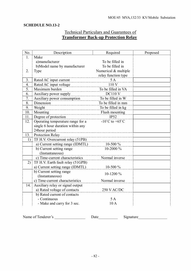
MOE/45 MVA,132/33 KV/Mobile Substation
- 82 -
SCHEDULE NO.13-2
Technical Particulars and Guarantees of Transformer Back-up Protection Relay
No. Description Required Proposed 1. Make
a)manufacturer
To be filled in
b)Model name by manufacturer To be filled in 2. Type Numerical & multiple
relay function type
3. Rated AC input current 5 A 4. Rated AC input voltage 110 V 5. Maximum burden To be filled in VA 6. Auxiliary power supply DC110 V 7. Auxiliary power consumption To be filled in W 8. Dimension To be filled in mm 9. Weight To be filled in kg 10. Mounting Flush mounting 11. Degree of protection IP52 12. Operating temperature range for a
single 6 hour duration within any 24hour period
-10˚C to +65˚C
13. Protection Relay 1) TF H.V. Overcurrent relay (51PB)
a) Current setting range (IDMTL) 10-500 %
b) Current setting range (Instantaneous)
10-2000 %
c) Time-current characteristics Normal inverse 2) TF H.V. Earth fault relay (51GPB)
a) Current setting range (IDMTL) 10-500 %
b) Current setting range (Instantaneous) 10-1200 %
c) Time-current characteristics Normal inverse 14. Auxiliary relay or signal output
a) Rated voltage of contacts 250 V AC/DC
b) Rated current of contacts - Continuous - Make and carry for 3 sec.
5 A
10 A
Name of Tenderer’s ________________ Date__________ Signature_______________

MOE/45 MVA,132/33 KV/Mobile Substation
- 83 -
SCHEDULE NO.13-3
Technical Particulars and Guarantees of Transformer L.V Protection & Control Relay
No. Description Required Proposed 1. Make
c) manufacturer
To be filled in
d) Model name by manufacturer To be filled in 2. Type Numerical & multiple
relay function type
3. Rated AC input current 5 A 4. Rated AC input voltage 110 V 5. Maximum burden To be filled in VA 6. Auxiliary power supply DC110 V 7. Auxiliary power consumption To be filled in W 8. Dimension To be filled in mm 9. Weight To be filled in kg 10. Mounting Flush mounting 11. Degree of protection IP52 12. Operating temperature range for a
single 6 hour duration within any 24hour period
-10˚C to +65˚C
13. Protection Relay on TF L.V. side 1) Under-voltage relay (27S)
a) Voltage setting range 10-100 % b) Time setting 0-60 Sec.
2) Under-frequency relay (81) a) Number of stages Not less than 2 a) Setting range of frequency 35-75 Hz for each stage b) Time setting 0-60Sec.for each stage
3) Overvoltage earthfault relay (64V) a) Voltage setting 2-100 % b) Time setting 0-60 Sec.
4) Phase sequence voltage Relay on L.V side of Aux.Earthing TF(47L)
a) Voltage setting 2-100 % b) Time setting 0-60 Sec.
10) Auxiliary relay or signal output a) Rated voltage of contacts 250 V AC/DC
b) Rated current of contacts - Continuous - Make and carry for 3 sec.
5 A
10 A
Name of Tenderer’s _______________ Date__________ Signature_______________

MOE/45 MVA,132/33 KV/Mobile Substation
- 84 -
SCHEDULE NO.13-4
Technical Particulars and Guarantees of Medium Voltage Feeder Protection Relay
No. Description Required Proposed 1. Make
a) manufacturer
To be filled in
b) Model name by manufacturer To be filled in 2. Type Numerical & multiple
relay function type
3. Rated AC input current 5 A 4. Rated AC input voltage 110 V 5. Maximum burden To be filled in VA 6. Auxiliary power supply DC110 V 7. Auxiliary power consumption To be filled in W 8. Dimension To be filled in mm 9. Weight To be filled in kg 10. Mounting Flush mounting 11. Degree of protection IP52 12. Operating temperature range for a
single 6 hour duration within any 24hour period
-10˚C to +65˚C
13. Protection Relay 1) Overcurrent relay (51F)
a) Current setting range (IDMTL) 30-250 % b) Current setting range (Instantaneous)
50-2000 %
c) Time-current characteristics Normal inverse 2) Earthfault relay (51GF)
a) Current setting range(IDMTL) 1-100 % b) Current setting range (Instantaneous) 5-800 %
c) Time-current characteristics Normal inverse 3) 3-phase Auto-reclosing relay (79F)
a) Number of reclosing shots 3 b) Deadtime 0.2-300 Sec. c) Reclaim time 3-300 Sec.
4) Trip circuit supervision (TCS) a) Quantity One for each CB b) Alarm delay time setting 0-300 Sec.
14. Auxiliary relay or signal output a) Rated voltage of contacts 250 V AC/DC b) Rated current of contacts - Continuous - Make and carry for 3 sec.
5 A
10 A
Name of Tenderer’s ________________ Date__________ Signature_______________

MOE/45 MVA,132/33 KV/Mobile Substation
- 85 -
SCHEDULE NO.14-1
Technical Particulars and Guarantees of 36 kV Power Cables for Incoming
No. Description 36 kV Incoming Required Proposed
1. Make To be filled in 2. Type CU/XLPE/PVC 3. Rated voltage 18/30 (36) kV 4. Construction data 1) Number of conductor 1 Core
2) Cross sectional area (Phase) 500 mm2 3) Shape of conductor Circular stranded
compacted
4) Material of conductor Copper 5) Number of wires (Min.) 53 6) Material of conductor shielding Semi conductive
compound
7) Thickness of conductor shielding (Approx.) 0.6 mm 8) Material of insulation XLPE 9) Thickness of insulation (Nominal) 8.0 mm 10) Material of insulation shielding Strippable semi-
conductive compound
11) Thickness (Approx.) 1.0 mm 12) Material of shielding Copper taps 13) Thickness of copper tape (Approx.) 1 nos. x 0.1 mm 13) Material of sheath PVC 14) Thickness of sheath (Nominal) 2.6 mm 15) Material of armor N.A 16) Color of sheath Black 17) Overall diameter of cable (Approx.) 51 mm 18) Marking of cable To be filled in 19) Net weight (Approx.) To be filled in (kg/km)
5. Electrical data 1) AC. withstand voltage for 5 minutes 63 kV 2) Impulse withstand voltage 170 kV 3) Max. DC. conductor resistance at 20˚C 0.0366 ohm/km 4) Max. Temperature rating of conductor 90 ˚C 5) Max. current rating (touching flat formation) in ground at 20˚C 810 A (*1)
6) Rated Frequency 50 Hz 7) Max. Partial discharge at 31.2kV 10 pC
6. Drawing No. To be filled in (*1) Depth of laying = 0.8 m, S=2d Name of Tenderer’s ________________ Date__________ Signature_______________

MOE/45 MVA,132/33 KV/Mobile Substation
- 86 -
SCHEDULE NO.14-2
Technical Particulars and Guarantees of 36 kV Power Cables for Feeder
No. Description 36 kV Feeder Required Proposed
1. Make To be filled in 2. Type CU/XLPE/PVC
with ARMOUR
3. Rated voltage 18/30 (36) kV 4. Construction data 1) Number of conductor 1 Core
2) Cross sectional area (Phase) 150 mm2 3) Shape of conductor Circular stranded
compacted
4) Material of conductor Copper 5) Number of wires (Min.) 18 6) Material of conductor shielding Semi conductive
compound
7) Thickness of conductor shielding (Approx.) 0.6 mm 8) Material of insulation XLPE 9) Thickness of insulation (Average) 8.0 mm 10) Material of insulation shielding Strippable semi-
conductive compound
11) Thickness of insulation shielding (Approx.) 1.0 mm 12) Material of shielding metallic taps 13) Thickness of metallic tape (Approx.) 1 nos. x 0.085 mm 13) Material of sheath PVC 14) Thickness of separation sheath (Average) 2.4 mm 15) Material of armour Aluminium wire 16) Diameter of aluminium wire (Nominal) 2.5 mm 16) Colour of sheath Black 17) Overall diameter of cable (Approx.) 46 mm 18) Marking of cable To be filled in 19) Net weight (Approx.) To be filled in (kg/km)
5. Electrical data 1) AC. withstand voltage for 5 minutes 63 kV 2) Impulse withstand voltage 170 kV 3) Max. DC. conductor resistance at 20˚C 0.124 ohm/km 4) Max. Temperature rating of conductor 90 ˚C 5) Max. current rating (touching flat formation) in ground at 20˚C 420 A (*1)
6) Rated Frequency 50 Hz 7) Max. Partial discharge at 32 kV 10 pC
6. Drawing No. To be filled in (*1) Depth of laying = 0.8 m, S=2d Name of Tenderer’s ________________ Date__________ Signature_______________

MOE/45 MVA,132/33 KV/Mobile Substation
- 87 -
SCHEDULE NO.15
Technical Particulars and Guarantees of
Low Voltage Power Cables
Name of Tenderer’s ________________ Date__________ Signature_______________
No. Description Required Proposed 1. Make To be filling in 2. Type Cu/XLPE/PVC 3. Location of service Outdoor 4. Rated voltage 6 00 V 5. Number of cores 4 6. Type of insulation materials XLPE 7. Type of sheath materials PVC 8. cable size 60 mm2 9. Conductor
a) Materials Copper b) Strands 19/Smooth body c) Outer diameter (Approx.) 9.3 mm
10. Thickness of insulation (Nominal) 1.5 mm 11. Thickness of sheath (Nominal) 2.0 mm 12. Overall diameter (Approx. ) 34 mm 13. Conductor resistance at 20˚C (Maximum) 0.311 ohm/km 14. Insulation resistance (Minimum) 1500 M-ohm km 15. AC. withstand voltage 2500 V 16. Net weight of cable (Approx.) To be filled in
(kg/km)

MOE/45 MVA,132/33 KV/Mobile Substation
- 88 -
SCHEDULE NO.16
Technical Particulars and Guarantees of
Plug in Type Connectors of Control cable
(for connection between Trailers No.1 & 2)
Name of Tenderer’s ________________ Date__________ Signature_______________
No. Description Required Proposed 1. Make To be filling in 2. Type Plug in with
water proof & dust proof type
3. Location of service Outdoor 4. Applicable temperature
a) Minimum temperature -55 °C b) Maximum temperature +85 °C
5. Number of pins 27 6. Type of contact40 km/h Crimp pin & crimp
socket contact
7. Applicable wire size 2.0 to 3.5 mm2 8. Rated voltage AC 1000 V 9. Rated current (Max. ) 23 A for 3.5mm2
17A for 2.0mm2
10. Contact resistance (at DC 35 A) less than 20 mV 11. Contact mating force Less than 40 N 12. Contact retention ( Axis load ) Not less than 66 N 13. Contact engagement force Max. 22.2 N 14. Contact separation force Min. 0.83 N 15. Insulation resistance (more than) 5000 MΩ 16. AC. withstand voltage AC 3000 V r.m.s.

MOE/45 MVA,132/33 KV/Mobile Substation
- 89 -
SCHEDULE NO.17-1
Technical Particulars and Guarantees of
132 kV ACSR Incoming Conductor
No. Description Required Proposed 1. Make To be filled in 2. Type (tubular, stranded, flat) Stranded 3. Material of conductor
a) Aluminium
Hard drawn aluminium wire
b) Steel Galvanized steel wire
4. Core name LARK 5. Conductor size 397.5 MCM 6. Number. and Diameter. of conductor
a) Aluminum 30 No. /2.924 mm b) Steel 7 No. /2.924 mm
7. approx. diameter a) ACSR 20.47 mm b) Steel 8.77 mm
8. Calculated sectional area a) Aluminium 201.4 mm2 b) Steel 47.01 mm2 c) ACSR 248.5 mm2
9. Rated current 525 A 10. Temperature rise 90 ˚C 11. Calculated electrical resistance 0.1437 Ohm/km
( at 20˚C )
12. Rated strength of conductor 90.4 kN 13. Approx. weight of ACSR To be filled in
(kg / km)
Name of Tenderer’s ________________ Date__________ Signature_______________

MOE/45 MVA,132/33 KV/Mobile Substation
- 90 -
SCHEDULE NO.17-2
Technical Particulars and Guarantees of
132 kV HDCC Conductor for Connection
No. Description Required Proposed 1. Make To be filling in 2. Type (tubular, stranded, flat) Stranded 3. Location of service Outdoor 4. Material Copper 5. Nominal sectional area 100 mm2 6. Number and diameter of wire 19 No. /2.6 mm 7. Approx. overall diameter 13.0 mm 8. Calculated breaking load 39.4 kN 9. Calculated DC. Resistance at 20˚C 0.178 ohm/km 10. Rated current 434 A 11. Temperature rise 90 ˚C 12. Maximum working tension 15.7 kN 13. Approx. weight To be filled in
( kg/km)
Name of Tenderer’s ________________ Date__________ Signature_______________

MOE/45 MVA,132/33 KV/Mobile Substation
- 91 -
SCHEDULE NO.17-3
Technical Particulars and Guarantees of
132 kV HAL Conductor for Connection
No. Description Required Proposed 1. Make To be filled in 2. Type (tubular, stranded, flat) Stranded 3. Location of service Outdoor 4. Material Aluminium 5. Nominal sectional area 150 mm2 6. Number and diameter of wire 19 No. /3.2 mm 7. Calculated sectional area 152.8 mm2 8. Approx. overall diameter 16.0 mm 9. Calculated breaking load 22.3 kN 10. Calculated DC. Resistance at 20˚C 0.188 ohm/km 11. Rated current 444 A 12. Temperature rise 90 ˚C 13. Maximum working tension 8.9 kN 14. Approx. weight To be filled in
(kg/km)
Name of Tenderer’s ________________ Date__________ Signature_______________

MOE/45 MVA,132/33 KV/Mobile Substation
- 92 -
SCHEDULE NO.18-1
Technical Particulars and Guarantees of
132 kV Single Tension Insulator String
No. Description Required Proposed 1. Make To be filled in 2. Material of anchor shackle Steel
Hot dip galvanized
3. Material of horn holder ball eye Steel Hot dip galvanized
4. Material of arcing horn Steel Hot dip galvanized
5. Disk insulator a) Diameter (Nominal) 254 mm b) Creepage distance (Nominal) 455 mm/unit c) Electromechanical failing load 120 kN d) Dry lightning impulse withstand voltage 125 kV e) Wet power frequency withstand voltage 45 kV f) Power frequency puncture voltage 130 kV g) Material Porcelain h) Colour Brown
6. Tension insulator single assembly a) Number of insulator unit per string 12 units b) Length of insulator 1752 mm c) Arcing hone gap 1532 mm d) Single insulator assembly length 2454 mm e) Creepage distance (Min.) 31.5 mm/kV f) Dry lightning impulse withstand voltage 650 kV/peak g) One-minute wet 50Hz withstand voltage 275 kV
7. Material of horn holder socket eye Ductile iron Hot dip galvanized
8. Material of tension clamp Aluminium alloy 9. Suitable conductor size of clamp ACSR “LARK” 10. Min. breaking strength of string 120 kN 11. Type of ball and socket parts IEC 16 mmA 12. Mass of insulator To be filling in (Kg) 13. Mass of fittings To be filling in (Kg) 14. Reference number of drawing for complete
set of insulator strings To be filling in
15. Drawing No. To be filled in
Name of Tenderer’s ________________ Date__________ Signature_______________

MOE/45 MVA,132/33 KV/Mobile Substation
- 93 -
SCHEDULE NO.18-2
Technical Particulars and Guarantees of
132kV Single Suspension Insulator String
No. Description Required Proposed 1. Make To be filled in 2. Material of anchor shackle Steel
Hot dip galvanized
3. Material of horn holder ball eye Steel Hot dip galvanized
4. Material of arcing horn Steel Hot dip galvanized
5. Disk insulator a) Diameter (Nominal) 254 mm b) Creepage distance (Nominal) 455 mm/unit c) Electromechanical failing load 120 kN d) Dry lightning impulse withstand voltage 125 kV e) Wet power frequency withstand voltage 45 kV f) Power frequency puncture voltage 130 kV g) Material Porcelain h) Colour Brown
6. Suspension insulator single assembly a) Number of insulator unit per string 12 units b) Length of insulator 1752 mm c) Arcing hone gap 1532 mm d) Single insulator assembly length 2454 mm e) Creepage distance (Min.) 31.5 mm/kV f) Dry lightning impulse withstand voltage 650 kV/peak g) One-minute wet 50Hz withstand voltage 275 kV
7. Material of horn holder socket eye Ductile iron Hot dip galvanized
8. Material of suspension clamp Aluminium alloy 9. Material of armour rod Aluminium alloy 9. Suitable conductor size of clamp ACSR “LARK” 10. Min. breaking strength of string 120 kN 11. Type of ball and socket parts IEC 16 mmA 12. Mass of insulator To be filling in (Kg) 13. Mass of fittings To be filling in (Kg) 14. Reference number of drawing for complete
set of insulator strings To be filling in
15. Drawing No. To be filling in
Name of Tenderer’s ________________ Date__________ Signature_______________

MOE/45 MVA,132/33 KV/Mobile Substation
- 94 -
SCHEDULE NO.19
Technical Particulars and Guarantees of
132kV Post Insulator
No. Description Required Proposed 1. Make To be filled in 2. Type Solid-core 3. Rated voltage 145 kV 4. Dry impulse withstand voltage 650 kV peak 5. One minute wet 50Hz withstand voltage 275 kV 6. Minimum failing load
a) Bending-Upright 10000 N b) Tension 90000 N c) Torsion 7000 N-m
7. Minimum Creepage path a) Protected
2170 mm
b) Total 5180 mm 8. Mass of insulator Approx. 105 Kg 9 Material of insulator Porcelain
10. Color of insulator Brown 11. Structure
a) Material Steel b) Type of Steel SS400
12. Corrosion protection of steel structure Zinc coating Min. 600g/m2
13. Height of steel structure (Min.) 2500 mm 14. Mass of steel structure To be filled in (kg) 15. Drawing No. To be filling in
Name of Tenderer’s ________________ Date__________ Signature_______________

MOE/45 MVA,132/33 KV/Mobile Substation
- 95 -
SCHEDULE NO.20
Technical Particulars and Guarantees of
Steel Structures for 132kV Incoming Gantry
No. Description Required Proposed 1. Make To be filled in 2. Steel members
a) Type of steel
SS400 b) Yield point (Min.) 245 N/mm2
3. Steel bolts a) Type of steel
SS400
b) Yield point (Min.) 235 N/mm2 4. Maximum design stresses
a) Tension and bending members stress
157 N/mm2
b) Shearing stress (bolts) 88 N/mm2 c) Bearing stress (bolts) 147 N/mm2 d) Compression members l/i ratio
(slenderness) less than 120
5. Zinc coating (Min.) 600 g/m2 6. Minimum bolts diameter 10 mm 7. Drawing No. To be filled in
Name of Tenderer’s ________________ Date__________ Signature_______________

MOE/45 MVA,132/33 KV/Mobile Substation
- 96 -
SCHEDULE NO.21-1
Technical Particulars and Guarantees of
Trailer No.1
No. Description Required Proposed 1. Make To be filled in 2. Type Drop-bed semi-trailer 3. Tractor (make and type) To be filled in 4. Principal dimension and weight
a) Overall length
To be filled in (mm)
b) Overall width To be filled in (mm) c) Overall height (unladed) To be filled in (mm) d) Floor height To be filled in (mm) e) Wheel base To be filled in (mm) f) Tare weight To be filled in (kg) g) Maximum payload To be filled in (kg) h) Gross vehicle weight To be filled in (kg)
5. Distribution weight a) Unladen - King pin (front axle) - Rear axle
To be filled in (kg) To be filled in (kg)
b) Laden - King pin (front axle) - Rear axle
To be filled in (kg) To be filled in (kg)
6. Size and quantity of Tire & wheel a) Tire - Front axle - Fear axle
To be filled in To be filled in
b) wheel - Front axle - Rear axle
To be filled in To be filled in
7. Type of Service brake Air “S” cam type 8. Type of parking brake Valve operating, spring
loaded chamber
9. Type of suspension Triple spring type 10. Type of landing gears Left and right combined
operation, high and low speed range, manual
operation with square pads
11. Type of vehicle coupling device (king pin) SAE 3.5 inches
12. Electric system a) Voltage
24 V
b) Receptacle type 7 poles (SAE) 13. Colour of Signal lamps
a) Tail, stop & parking
Combined (red)
b) Turn signal & hazard Combined (orange) c) License lamp White

MOE/45 MVA,132/33 KV/Mobile Substation
- 97 -
No. Description Required Proposed 14. Flooring materials Checked steel plate 15. Speed limit 40 km/h
Name of Tenderer’s ________________ Date__________ Signature_______________

MOE/45 MVA,132/33 KV/Mobile Substation
- 98 -
SCHEDULE NO.21-2
Technical Particulars and Guarantees of
Trailer No. 2
No. Description Required Proposed 1. Make To be filled in 2. Type Low-bed semi-trailer 3. Tractor (make and type) To be filled in 4. Principal dimension and weight
a) Overall length
To be filled in mm
b) Overall width To be filled in mm c) Overall height (unladed) To be filled in mm d) Floor height To be filled in mm e) Wheel base To be filled in mm f) Tare weight To be filled in kg g) Maximum payload To be filled in kg h) Gross vehicle weight To be filled in kg
5. Distribution weight a) Unladen - King pin (front axle) - Rear axle
To be filled in kg To be filled in kg
b) Laden - King pin (front axle) - Rear axle
To be filled in kg To be filled in kg
6. Size and quantity of Tire & wheel a) Tire - Front axle - Fear axle
To be filled in To be filled in
b) wheel - Front axle - Rear axle
To be filled in To be filled in
7. Type of Service brake Air “S” cam type 8. Type of parking brake Valve operating, spring
loaded chamber
9. Type of suspension Tandem spring type 10. Type of landing gears Left and right combined
operation, high and low speed range, manual
operation with square pads
11. Type of vehicle coupling device (king pin) SAE 3.5 inches
12. Electric system a) Voltage
24 V
b) Receptacle type 7 poles (SAE) 13. Color of Signal lamps
a) Tail, stop & parking
Combined (red)
b) Turn signal & hazard Combined (orange) c) License lamp White

MOE/45 MVA,132/33 KV/Mobile Substation
- 99 -
No. Description Required Proposed 14. Flooring materials Checked steel plate 15. Speed limit 40 km/h
Name of Tenderer’s ______________ Date__________ Signature

MOE/45 MVA,132/33 KV/Mobile Substation
- 100 -
Section-2.5 : Typical Layout Drawing and Single Line Diagrams
- Typical Layout of 31.5 MVA Mobile substation Dwg. No. - 132/33 kV 31.5 MVA Mobile S/S Single Line Diagram Dwg. No.

MOE/45 MVA,132/33 KV/Mobile Substation
- 101 -
Part-3 Maintenance materials and Trainings
Section-3.1 : Spare Parts, Testing Equipment & General Tools 3.1.1. Spare parts
Spare parts are classified into 2 categories as follows; a) consumable spare parts which are allocated for each Mobile substation b) spare parts covered for the overall contract equipment which are reserved under
O & M management for maintenance purposes. 3.1.1.1.Consumable spare pars for each Mobile substation
Typical spare part items and quantity required are as follows. Quantity shown in the list is for one Mobile substation.
No. Item Rating /Description Quantity
1 Fuse for space heater of 145kV CB 2 pcs
2 Recording paper for surge recorder 10 sheets in box 1 box
3 Dehydrating agent for breather for power transformer
1) Silica gel for main tank 2) Ditto for OLTC
Each 3 sets
4 Dehydrating agent for breather for Aux. Earthing transformer Silica gel 1 kg/can 1 pc.
5 Lamp with lens for medium voltage switchgears 2 pcs
6 Fuses for Battery and charger For each rating Each 2 pcs
7 Signal lamp with lens for control panel For each rating Each
2 pcs
8 Maintenance material
Cable tie, Touch up paint 5Y7/1 Self-adhesive insulation tape
1 set
9 Signal lamp for trailer Tail & Stop, Turn signal, License, Back-up, Side, Clearance,
Each 1 pc.
3.1.1.2. Spare pars for the contract
Basic philosophy is that the quantity required is calculated as five (for 5 regions) times minimum quantity of each item or set of parts. Typical spare part items and quantity are as follows. Contractor is requested to propose an appropriate min. quantity for each item.
1) 145kV Vacuum circuit breaker:
No. Description Rating Quantity 1 Closing coil DC 110V 10 pcs 2 Trip coil DC 110V 10 pcs
3 Set of Magnet contactor DC110V Each 10 pcs
4 Auxiliary switch 6NO, 6NC 10 pcs 5 Motor for spring charge DC110V 10 pcs 6 Set of limit switch (each type) DC110V 10 pcs 7 No voltage tripping coil & voltage
relay 84 DC110V 10 pcs

MOE/45 MVA,132/33 KV/Mobile Substation
- 102 -
2) 120kV Lightning Arrester:
No. Description Rating Quantity 1 LA for 132kV Line 120kV 10kA 15 pcs 2 Surge Counter For 132kV Line 5 pcs 3 Surge Recorder For 132kV Line 15 pcs
3) 31.5MVA Power TF:
No. Description Rating Quantity
1 H.V Bushing with gaskets Oil-filled condenser type, 145kV, Creepage Distance: 31mm/kV 15 pcs
2
BCT on H.V Bushing Oil immersed type as follows: 1) For metering 200/5A 15VA Class 1.0 5 pcs 2) For Main protection 200/5A Class X 5 pcs 3) For Back-up protection 200/5A 15VA 5P10 5 pcs
3 H.V Neutral Bushing with gaskets
Oil-filled condenser type, 72.5kV 800A, Creepage Distance: 31mm/kV
5 pcs
4 BCT on Neutral Bushing Oil immersed type, 200/5A Class X 5 pcs 5 36kV Bushing with gaskets Solid type 15 pcs 6 12kV Bushing with gaskets Solid type N.A.
7 Set of gaskets For 132/33kV
each 5 sets
8 Cooling fan 5 pcs 9 Oil pump 5 pcs 10 Buchholz relay for Main tank 5 pcs 11 Pressure relay for OLTC 5 pcs 12 Oil temperature relay 5 pcs 13 Winding temperature relay 5 pcs
14 Dial type oil gauge for Main tank and OLTC each
5 pcs
15 Dehydrating breather for Main tank Silica gel 5 pcs
16 Dehydrating breather for OLTC Silica gel 5 pcs 17 Motor for OLTC drive AC 380V 3-phase 5 pcs 18 LA at 132 kV Neutral point 75 kV 10 kA 5 pcs
19 Insulating oil (10% of total quantity of oil)
SHELL- DIALA- B or equivalent (bendable with SHELL-DIALA-B) 5 lots

MOE/45 MVA,132/33 KV/Mobile Substation
- 103 -
4) Auxiliary Earthing transformer:
No. Description Rating Quantity
1 36 kV Line bushing with gaskets Solid type 5 pcs
2 36 kV side Neutral Bushing with gaskets Solid type 5pcs
3 12 kV Line Bushing with gaskets Solid type N.A.
4 12 kV side Neutral Bushing with gaskets Solid type N.A.
5 L.V Line & Neutral Bushing with gaskets
For 380V line, Solid type 5 pcs
6 LA at 33 kV neutral point 21 kV / 10 kA 5 pcs 7 LA at 11.5 kV neutral point 7.5 kV / 10 kA N.A. 8 Buchholz relay 5 pcs 9 Dial type oil gauge 5 pcs 10 Dehydrating breather Silica gel 5 pcs 11 BCT on 33 kV Neutral point Oil immersed type, 600/5A Class X 5 pcs
12 BCT on 11.5 kV Neutral point Oil immersed type, 1500/5A Class X N.A.
13 Set of gasket For 33/0.38kV Aux.E.TF Each 5 sets
14 Insulating oil (10% of total quantity of oil)
SHELL- DIALA- B or equivalent (blendable with SHELL-DIALA-B) 5 lots
5) 36kV switchgear:
No. Description Rating Quantity
1 Compete VCB for Incomer & Outgoing feeder 36 kV 630A, 31.5kA Each
5 units
2 Single phase voltage transformer for 33 kV line 33 kV/√3 /110V/√3 / 110V/3
200VA, Class.1.0/3P 15 pcs
3 H.V Fuse for 33 kV VT 36 kV, 25kA 15 pcs
4 CT for Incomer 1) 600-300/5A Class 1.0 15VA 2) 600-300/5A Class X
Each 15 pcs
5 CT for Outgoing feeder 600-300/5-5A Class 5P10 /1.0 2x7.5VA or more
Each 15 pcs
6 Lightning arrester 39 kV / 10 kA 5 pcs 7 Closing coil DC 110V 10 pcs 8 Trip coil DC 110V 10 pcs 9 Magnet contactor DC 110V 10 sets 10 Anti-pumping relay DC 110V 10 sets 11 Spring charge motor DC 110V 10 pcs 12 VD + Indicator DC 110V 10 sets

MOE/45 MVA,132/33 KV/Mobile Substation
- 104 -
6) Battery and charger:
No. Description Rating Quantity 1 Spare Battery cell Empty cell Ni-Cd type 200 pcs
2 Electrolyte for spare battery 20 litter plastic containers 20 pcs
3 Parts for Rectifier Unit for charger Rectifier stack
5 sets
4 Parts for DC output Voltage Regulator Diode stack for Silicone dropper
5 sets
5 Pulse generator and control unit 5 sets
6 Low electrolyte relay DC110V 5 pcs 7 DC earth fault relay DC110V 5 pcs 8 Under voltage relay (80X) DC110V 5 pcs 9 Group fault indicator 5 pcs
10 Ammeter and Volt meter For each type each 5 pcs
11 Set of switches For each type each 5 pcs
12 Set of Moulded Case Circuit Breakers For each rating each
5 pcs
13 Set of fuses For each rating each 10pcs

MOE/45 MVA,132/33 KV/Mobile Substation
- 105 -
8) Supervisory control, protection panel & AC distribution board:
No. Description Rating Quantity
1 Set of Signal lamp & Indication lamp For each type each
10pcs
2 Set of Control switch & Push button switch For each type each
10pcs
3 Multi-meter for transformer primary (AM with AS) 5 pcs
4
Multi-meter for transformer secondary (AM with AS, VM with VS, WM with MDI, WHI, VarM)
For each type Each 5 pcs
5 Multi-meter for Outgoing feeder (AM with AS, WM with MDI, WHI)
For each type Each 5 pcs
5 Multi-meter for Aux.G.TF LV side (AM with AS, VM with VS) For each type Each
5 pcs 6 Tap position indicator Rectangular 5 pcs
7 Numerical multi-function transformer protection relay
1) Transformer main protection 2) Transformer back-up protection
each 5 sets
8 Automatic Voltage Regulating relay (AVR) included in TF main protection 0
9 Numerical multi-function feeder protection relay
10 sets
10 Phase sequence relay for AC distribution circuit included in TF main protection 0
11 Set of Annunciator card and LED lamp For each type each
5 pcs
12 Set of Auxiliary relay For each type and rating each 5 pcs
13 Set of Molded Case Circuit Breaker For each type and rating each
5 pcs
14 Set of fuses For each type and rating each 10pcs
15 Filter for air-conditioning equipment For each type Each
5 pcs 3.1.2. Testing equipment for the overall contract
3.1.3. General Tools

MOE/45 MVA,132/33 KV/Mobile Substation
- 106 -
Section-3.2 : Training for 31.5MVA Mobile Substation
Trainings are classified into 2 categories as follows; 1. Training for operation and maintenance of Mobile substations 2. Training for Installation works of Mobile substations
3.2.1 Training for operation and maintenance:
The Contractor shall provide training on operation and maintenance of Mobile substations as follows;
1) Training place;
Training place shall be at manufacture’s factory or its relevant facility for Mobile Substation.
2) The number of MOE trainees and term for training;
a) Number : Total 6 persons
b) Term : 12 days (8 working days for substantial training period)
3) Expenses associated with Training
Expenses such as transportation charge (air fares between Iraq and countries where the trainings are carried out, and Domestic travels in those countries), and accommodation charge shall be provided by the contractor.
4) Minimum items of equipment and components of training.
a) 145kV Disconnecting switch and earthing switch
b) 145kV Circuit Breaker
c) 31.5MVA Main Transformer & Auxiliary Earthing transformer
d) 36 kV
e) Supervisory Control and Protection Panel
f) Protection Relays
g) Battery and Charger (including initial charging of batteries) 3.2.2 Training for Installation works:
The Contractor shall provide training on Earth work for the site, installation work, site-test of Mobile substations as follows;
1) Training place ;
Training place shall be manufacture’s factory or its relevant facility for Mobile Substation

MOE/45 MVA,132/33 KV/Mobile Substation
- 107 -
2) The number of MOE trainees and term for training;
a) Number : Total 6 persons
b) Term : 12 days (8 working days for substantial training period) 3) Expenses associated with Training
Expenses such as transportation charge ( air fares between Iraq and countries where the trainings are carried out, and Domestic travels in those countries), and accommodation charge shall be provided by the contractor.
4) Minimum items of training.
a) Earth work with necessary earth work equipment for site preparation (a Lecture on text book basis is acceptable)
b) Electrical Earthing work
c) Acceptance Inspection : Procedure of how to check of Impact recorder with evaluation (Pass/Fail) criteria
d) Process of every necessary Installation work (positioning/levelling and jack setting, 132kV bus bar connections, cable installation, earthing wire connection etc.) before site-test.