specification and description - suzanne webbwordslingingwoman.com/sd-manual-2015.pdf · 9.8...
TRANSCRIPT

SPECIFICATION AND DESCRIPTION
CITATION X+
SERIAL NUMBER 750-___ TO TBD
NOVEMBER 2015
REVISION F
Part 3
Purchaser’s Initials____
Seller’s Initials _______
ACTUAL GRAPHIC TO BE INCLUDED


i CITATION X+ • NOVEMBER 2015
TABLE OF CONTENTS
LIST OF FIGURES ..............................................................................................................................iv
INTRODUCTION ..................................................................................................................................1
THE AIRCRAFT................................................................................................................................... 2
1. GENERAL DESCRIPTION .................................................................................................... 2
1.1 Certification .................................................................................................................... 2
1.2 Purchaser’s Responsibility......................................................................................... 2
EXTERIOR DIMENSIONS ................................................................................................................ 3
INTERIOR DIMENSIONS.................................................................................................................. 4
1.3 Approximate Dimensions .......................................................................................... 5
1.4 Design Weights and Capacities .............................................................................. 5
2. PERFORMANCE .................................................................................................................... 5
3. DESIGN LIMITS ...................................................................................................................... 6
4. FUSELAGE ...............................................................................................................................7
4.1 Design and Construction ...........................................................................................7
4.2 Nose Section .................................................................................................................7
4.3 Interior Spaces ..............................................................................................................7
4.4 Aft Fuselage ................................................................................................................7
5. WING .........................................................................................................................................7
6. EMPANNAGE ..........................................................................................................................7
7. LANDING GEAR ..................................................................................................................... 8
7.1 Design and Construction ........................................................................................... 8
7.2 Nosewheel Steering ................................................................................................... 8
7.3 Brakes and Tires .......................................................................................................... 8
8. PROPULSION ......................................................................................................................... 8
8.1 Powerplant .................................................................................................................... 8
8.2 APU.................................................................................................................................. 9
9. SYSTEMS ................................................................................................................................ 9
9.1 Flight Controls .............................................................................................................. 9
9.2 Fuel System .................................................................................................................. 9
9.3 Electrical System ........................................................................................................10
9.4 Exterior Lighting System ..........................................................................................10

iiCITATION X+ • NOVEMBER 2015
TABLE OF CONTENTS CONT
9.4.1 Primary .................................................................................................................10
9.4.2 Secondary ..........................................................................................................10
9.5 Pressurization and Environmental System ......................................................... 11
9.6 Oxygen System ........................................................................................................... 11
9.7 Anti-Icing System and Rain Removal ..................................................................... 11
9.7.1 Ice ........................................................................................................................... 11
9.7.2 Rain ........................................................................................................................ 11
9.8 Hydraulic System ........................................................................................................ 11
10. FLIGHT COMPARTMENT .................................................................................................. 11
10.1 General ......................................................................................................................... 11
10.2 Instrumentation .........................................................................................................12
10.3 Avionics........................................................................................................................ 13
10.3.1 Flight Displays ................................................................................................... 13
10.3.1.1 Primary Flight Display (PFDs) ............................................................. 13
10.3.1.2 Multi-Function Display (MFD) .............................................................. 13
10.3.2 Garmin Touchscreen Control Panels (GTCs) ......................................... 13
10.3.3 Garmin’s Integrated Avionics Unit (GIA) .................................................. 13
10.3.3.1 Global Positioning System (GPS) ..................................................... 13
10.3.3.2 Very High Frequency Radio (VHF) ................................................. 14
10.3.3.3 High Frequency Radio Voice Communication .......................... 14
10.3.3.4 Navigation Receivers .......................................................................... 14
10.3.4 Data Link Services ........................................................................................ 14
10.3.5 Cockpit Voice Data Satellite Transceiver (Iridium) .............................. 14
10.3.6 Cockpit Voice Recorder (CVR) .................................................................. 14
10.3.7 Link 2000+ Controller-Pilot Datalink Communications (CPDLC) .... 14
10.3.8 Flight Management System (FMS) ........................................................... 14
10.3.9 Electronic Charts and Maps ......................................................................15
10.3.10 Distance Measuring Equipment (DME) ..................................................15
10.3.11 Engine Indicating System (EIS) ................................................................15
10.3.12 Crew Alerting System (CAS) ......................................................................15
10.3.13 Flight Guidance System (FGS) ..................................................................15

iii CITATION X+ • NOVEMBER 2015
TABLE OF CONTENTS CONT
10.3.14 Attitude/Heading System (AHS) ..............................................................16
10.3.15 Transponders with ADS-B Out Capability ............................................16
10.3.16 Weather Radar .............................................................................................16
10.3.17 Radio Altimeter..............................................................................................16
10.3.18 Traffic Collision Avoidance System (TCAS II) ......................................16
10.3.19 Terrain Awareness Warning System (TAWS) .......................................16
10.3.20 Synthetic Vision Technology (SVT) ........................................................ 17
10.3.21 Emergency Locator (ELT) ........................................................................... 17
10.3.22 Standby Instrumentation ........................................................................... 17
10.3.23 Maintenance Diagnostics ......................................................................... 17
11. INTERIOR ............................................................................................................................... 17
11.1 Cabin .............................................................................................................................. 17
11.2 Entertainment System ..............................................................................................19
11.3 Windows .......................................................................................................................19
11.4 Cabin Lighting System ............................................................................................19
11.4.1 Direct Lighting ...................................................................................................19
11.4.2 Indirect Lighting ...............................................................................................19
11.4.3 Emergency Lighting ........................................................................................19
11.5 In Flight Phone System ............................................................................................19
12. EXTERIOR ........................................................................................................................... 20
12.1 Exterior Storage ...................................................................................................... 20
13. LOOSE EQUIPMENT ....................................................................................................... 20
14. EMERGENCY EQUIPMENT .............................................................................................21
15. DOCUMENTATION AND TECHNICAL PUBLICATIONS ........................................21
16. MAINTENANCE TRACKING PROGRAM ...................................................................22
17. LIMITED WARRANTIES .....................................................................................................23
17.1 Seller’s Citation X+ Limited Aircraft Warranty (Limited Warranty) ..............23
17.2 Rolls-Royce Engine Warranty ...............................................................................25
17.3 Summary of Honeywell APU Warranty ..............................................................28
18. TRAINING AGREEMENT ................................................................................................29
APPENDIX A: COMMON ACRONYMS ......................................................................................31

ivCITATION X+ • NOVEMBER 2015
LIST OF FIGURESFigure 1: Exterior Dimensions . . . . . . . . . . . . . . . . . . . . . . . . . . . . . . . . . . . . . . . . 3
Figure 2: Interior Dimensions . . . . . . . . . . . . . . . . . . . . . . . . . . . . . . . . . . . . . . . . 4
Figure 3: Instrumentation . . . . . . . . . . . . . . . . . . . . . . . . . . . . . . . . . . . . . . . . . . 12
Figure 4: Cabin / Typical Configuration . . . . . . . . . . .. . . . . . . . . . . . . . . . . . . . . 18

1 CITATION X+ • NOVEMBER 2015
INTRODUCTION This Specification and Description provides general information about the design, performance, and standard equipment of the Citation X+, Serial Number 750-____ to TBD (hereinafter “Citation X+” or “Aircraft”). Due to the lapse of time between the date of this publication and Aircraft delivery, Cessna Aircraft Company (hereinafter “Seller”) reserves the right to revise this Specification and Description when occasioned by product improvements, government regulations, or other good cause, as long as the revisions do not result in a material reduction in Aircraft performance. If there is a conflict between this Specification and Description and the Aircraft Purchase Agreement into which it is incorporated, the terms and conditions of the Aircraft Purchase Agreement control.
For further information contact:
Cessna Business OperationsCessna Aircraft CompanyP.O. Box 7706Wichita, Kansas 67277-7706
Telephone: 316-517-6000Fax: 316-517-6640E-Mail: [email protected]

2CITATION X+ • NOVEMBER 2015
THE AIRCRAFT
1. GENERAL DESCRIPTIONThe Cessna Citation X+ is a transcontinental swept-wing business jet. The aircraft has provisions for 8-12 passengers (and is certified for a crew of two; nine passengers is standard). The Citation X+ has several interior and two exterior storage compartments for personal items, baggage, and cargo. Two new generation Rolls-Royce AE3007C2 turbofan engines power the Citation X+, and a fully integrated Garmin G5000 digital avionics suite provides pilots with state-of-the-art touchscreen controls.
1.1 CertificationThe Citation X+ is certified in accordance with U.S. 14 CFR Part 25, Transport Category, including day, night, VFR, IFR, and flight into known icing conditions. The Citation X+ is compliant with RVSM certification requirements.
Note: Specific operator approval is required for operation within RVSM airspace; Seller offers a no-charge service to assist with this process.
1.2 Purchaser’s ResponsibilityInternational aircraft certification may require modifications to and the incorporation of additional equipment into the Aircraft. The Aircraft purchaser (“Purchaser”) is responsible for the costs of any such modifications and incorporation of additional equipment. In addition, the Purchaser is responsible for obtaining approval to operate the Aircraft from the relevant civil aviation authority and for understanding and complying with applicable crew requirements.

3 CITATION X+ • NOVEMBER 2015
EXTERIOR DIMENSIONS
Figure 1 [MEASUREMENTS TO BE INCLUDED]

4CITATION X+ • NOVEMBER 2015
INTERIOR DIMENSIONS
Figure 2[MEASUREMENTS TO BE INCLUDED]
5 CITATION X+ • NOVEMBER 2015
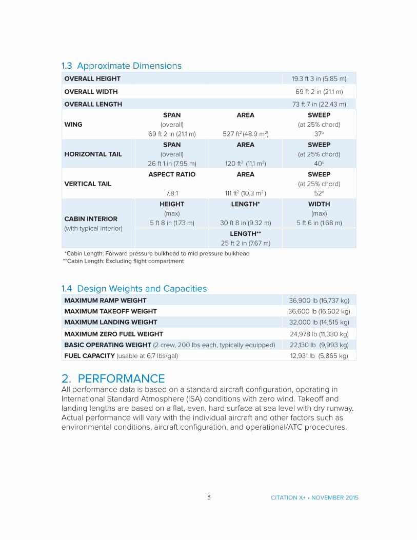
1.3 Approximate DimensionsOVERALL HEIGHT 19.3 ft 3 in (5.85 m)
OVERALL WIDTH 69 ft 2 in (21.1 m)
OVERALL LENGTH 73 ft 7 in (22.43 m)
WINGSPAN
(overall)
69 ft 2 in (21.1 m)
AREA
527 ft2 (48.9 m2)
SWEEP
(at 25% chord)
37o
HORIZONTAL TAILSPAN
(overall)
26 ft 1 in (7.95 m)
AREA
120 ft2 (11.1 m2)
SWEEP(at 25% chord)
40o
VERTICAL TAILASPECT RATIO
7.8:1
AREA
111 ft2 (10.3 m2 )
SWEEP(at 25% chord)
52o
CABIN INTERIOR (with typical interior)
HEIGHT(max)
5 ft 8 in (1.73 m)
LENGTH*
30 ft 8 in (9.32 m)
WIDTH(max)
5 ft 6 in (1.68 m)
LENGTH**25 ft 2 in (7.67 m)
*Cabin Length: Forward pressure bulkhead to mid pressure bulkhead **Cabin Length: Excluding flight compartment
1.4 Design Weights and CapacitiesMAXIMUM RAMP WEIGHT 36,900 lb (16,737 kg)
MAXIMUM TAKEOFF WEIGHT 36,600 lb (16,602 kg)
MAXIMUM LANDING WEIGHT 32,000 lb (14,515 kg)
MAXIMUM ZERO FUEL WEIGHT 24,978 lb (11,330 kg)
BASIC OPERATING WEIGHT (2 crew, 200 lbs each, typically equipped) 22,130 lb (9,993 kg)
FUEL CAPACITY (usable at 6.7 lbs/gal) 12,931 lb (5,865 kg)
2. PERFORMANCEAll performance data is based on a standard aircraft configuration, operating in International Standard Atmosphere (ISA) conditions with zero wind. Takeoff and landing lengths are based on a flat, even, hard surface at sea level with dry runway. Actual performance will vary with the individual aircraft and other factors such as environmental conditions, aircraft configuration, and operational/ATC procedures.

6CITATION X+ • NOVEMBER 2015
PERFORMANCE CONT.
TAKEOFF FIELD LENGTH
(Maximum Takeoff Weight, 15 degree Flaps, A/C and Bleed Air On)
5,250 ft (1,600 m)
MAXIMUM CERTIFIED ALTITUDE 51,000 ft (15,545 m)
MAXIMUM CRUISE SPEED (+/- 3%)
(35,000 feet {10.7 m} altitude; 30,000 pounds {13,608 kg} cruise weight;
maximum cruise thrust)
528 KTAS (978 km/hr)
MAXIMUM FERRY RANGE(Two crew, no payload, Mach 0.82, NBAA IFR Reserves with 200 NM
alternate)
3,460 NM (6,407.9 km)
NBAA IFR RANGE
(Max weight, full fuel payload, two crew, Mach 0.82, 200 NM alternate)
3,240 NM (6,000 km)
LANDING DISTANCE 3,330 ft (1,015 m)
CERTIFIED NOISE LEVELSComplies with 14 CFR 36, Appendix B, Stage 4 maximum noise level requirements / ICAO Chapter
4 noise levels in Annex 16, Volume 1, Appendix 2, Amendment 7
Flyover 72.4 EPNdB
Lateral 87.7 EPNdB
Approach 89.3 EPNdB
3. DESIGN LIMITSDESIGN LOAD LIMITS
Flaps UP (slats retracted) -1.00 to +2.70G
Flaps UP, 1, 2, or FULL (slats extended) 0.0 to +2.0G
OPERATING LIMIT SPEEDS
VMO (sea level to 8,000 ft {2,438 m}) 270 KIAS (500 km/hr)
VMO (8,000 ft {2,438 m} to 31,500 feet {9,601 m}) 350 KIAS (648 km/hr)
MMO (above 31,500 feet {9,601m}) Mach 0.935 (Indicated)
FLAP LIMIT SPEEDS
Maximum Slat Extended Speed 250 KIAS (463 km/hr)
Maximum Flap Extended Speed 210 KIAS (389 km/hr)
VFE (Flaps 1) 250 KIAS (463 km/hr)
VFE (Flaps 2) 210 KIAS (389 km/hr)
VFE (Flaps FULL) 180 KIAS (333 km/hr)
LANDING GEAR LIMIT SPEEDS
VLO 210 KIAS (389 km/hr)
VLE 210 KIAS (389 km/hr)
SPEED BRAKES
VSB No Limit

7 CITATION X+ • NOVEMBER 2015
4. FUSELAGE
4.1 Design and ConstructionThe Citation X+ incorporates a circular fuselage of metallic construction with an internal cabin. A continuous dropped aisle in the passenger cabin provides optimized cabin room and passenger comfort.
4.2 Nose SectionThe nose section has a contoured radome. The all-glass windshields meet bird resistance requirements of Part 25; they are electrically heated and defogged.
4.3 Interior SpacesThe flight compartment and cabin are described in Section 10 and 11, respectively.
4.4 Aft Fuselage The aft fuselage features a heated and pressurized baggage compartment and a utility cargo area, detailed in Section 12.1. The aft fuselage also features servicing ports for the hydraulic system and external toilet servicing. Area rule design has been incorporated to reduce drag.
5. WINGThis Aircraft features a highly swept wing utilizing super critical airfoil technology. Additionally, the design of the speed brakes and spoiler allow for drag control with minimum pitching moments. Also included are dual, hydraulically-powered non-reversible controls.
A large aerodynamic fairing further reduces drag. This fairing allows for a larger cabin environment as installed systems are housed within the fairing and not the fuselage itself. Three Fowler-type flaps and a leading edge slat, two roll spoilers, and three speed brake panels are incorporated into each wing.
The Citation X+’s winglets improve performance and help it climb to higher altitudes at heavier weights as well as depart at heavier weights/higher temperatures.
6. EMPANNAGEThe empennage features a highly swept T-tail with a movable horizontal stabilizer for trim. Elevators and the lower portion of a two-piece rudder are hydraulically powered while the upper portion of the rudder is electrically powered.
8CITATION X+ • NOVEMBER 2015
7. LANDING GEAR
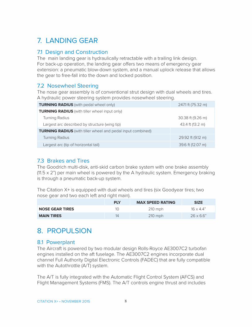
7.1 Design and ConstructionThe main landing gear is hydraulically retractable with a trailing link design. For back-up operation, the landing gear offers two means of emergency gear extension: a pneumatic blow-down system, and a manual uplock release that allows the gear to free-fall into the down and locked position.
7.2 Nosewheel SteeringThe nose gear assembly is of conventional strut design with dual wheels and tires. A hydraulic power steering system provides nosewheel steering.
TURNING RADIUS (with pedal wheel only) 247.1 ft (75.32 m)
TURNING RADIUS (with tiller wheel input only)
Turning Radius 30.38 ft (9.26 m)
Largest arc described by structure (wing tip) 43.4 ft (13.2 m)
TURNING RADIUS (with tiller wheel and pedal input combined)
Turning Radius 29.92 ft (9.12 m)
Largest arc (tip of horizontal tail) 39.6 ft (12.07 m)
7.3 Brakes and TiresThe Goodrich multi-disk, anti-skid carbon brake system with one brake assembly (11.5 x 2”) per main wheel is powered by the A hydraulic system. Emergency braking is through a pneumatic back-up system.
The Citation X+ is equipped with dual wheels and tires (six Goodyear tires; two nose gear and two each left and right main).
PLY MAX SPEED RATING SIZE
NOSE GEAR TIRES 10 210 mph 16 x 4.4”
MAIN TIRES 14 210 mph 26 x 6.6”
8. PROPULSION
8.1 PowerplantThe Aircraft is powered by two modular design Rolls-Royce AE3007C2 turbofan engines installed on the aft fuselage. The AE3007C2 engines incorporate dual channel Full Authority Digital Electronic Controls (FADEC) that are fully compatible with the Autothrottle (A/T) system.
The A/T is fully integrated with the Automatic Flight Control System (AFCS) and Flight Management Systems (FMS). The A/T controls engine thrust and includes

9 CITATION X+ • NOVEMBER 2015
speed and thrust modes. The A/T may be selected prior to initiating takeoff roll and remain engaged throughout the flight, approach, flare, and landing touchdown (Aircraft does not incorporate autoland capability). The A/T may be disengaged for manual throttle control.
Each engine features six large access panels for Line Replacement Unit (LRU) maintenance and multiple borescope inspection ports.
Hydraulically actuated, target-type thrust reversers compatible with the engine nacelles and powerplants are included.
TAKEOFF THRUST (at sea level) 7042 lbs (3194.2 kg)
FLAT RATED TO 86oF (35oC)
HOT SECTION INSPECTION* Every 4500 APU hours
*TBO: Rolls-Royce specifies a regular Hot Section Inspection every 4500 APU hours rather than an overhaul for this model engine.
8.2 APUCertified for in-flight use up to 31,000 feet, the Honeywell GTCP36-150(CX) APU provides engine start, power, and bleed air. The APU, which is located in the tailcone stinger for easy maintenance, can also be operated on the ground. The APU requires a Hot Section Inspection every 4,500 APU hours.
9. SYSTEMS
9.1 Flight ControlsThe Primary Flight Controls (PFC) are hydraulically powered with a dual, isolated hydraulic system and a manual backup. PFCs consist of one aileron on each wing, one elevator on each side of the horizontal tail, and two rudders on the vertical tail. All PFCs are hydraulically actuated from two independent power sources and can be manually operated via conventional cables for backup.
Secondary flight controls include electric trim, roll spoiler, speed brakes, and three Fowler-type flap panels per side, operated by a Direct Current (DC) system. All control surfaces, spoilers, speedbrakes, and flaps are of composite construction. A dual independent yaw damper system improves performance and comfort.
9.2 Fuel SystemThere are three separate fuel tanks: two wing tanks and one center tank, located in the center portion of the wing and the forward fuselage fairing. Fuel is transferred from the center tank to both wing tanks automatically using scavenge ejector pumps.
There are two independent fuel supply systems, one located in each wing tank.

10CITATION X+ • NOVEMBER 2015
Fuel is supplied to the engines and APU via motive flow driven primary ejector pumps. Fuel supply can also be provided by electric boost pumps during the engine start sequence, or in the event the primary ejector is not providing sufficient flow or pressure.
Both single point refueling and defueling, located near the right wing, can be operated without powering the aircraft. The Citation X+ is certified for a wide range of jet fuels. Total useable fuel is 12,931 lbs (5,865 kg).
9.3 Electrical SystemThe split-bus electrical system is powered by two engine-driven, 400 amp, brushless DC generators. A third generator is driven by the APU when the APU is operating. The aircraft’s main batteries are two 44-amp hour Nickel-Cadmium batteries, which are located in access panels on each side of the fuselage behind the wing.
An engine-driven alternating current (AC) system aids in de-icing and defogging the windshield. In the unlikely event of dual generator loss, the alternators can also provide backup electrical power through transformer-rectifier units to an essential electrical bus. The essential bus can power components of the G5000 system that are essential for flight, including two display units and the Flight Director functionality. The essential bus design and its multiple power sources provide greater reliability and situational awareness in the event of an electrical emergency. If all engine-driven power sources are lost, the aircraft main batteries provide power to the emergency bus for a limited period of time.
Innerconnect wiring eliminates static and provides a solution to High Intensity Radiated Fields (HIRF). Cabin electrical grounds are centralized for ease of access.
9.4 Exterior Lighting System
9.4.1 PrimaryStandard exterior lighting consists of two pulsing red LED lights for ground recognition, LED anti-collision lights, LED position lights, two landing/recognition lights (including the Precise Flight pulselite system which, when activated, pulses the landing/recognition lights), windshield ice detection lights, and taxi lights (located on the nose landing gear).
9.4.2 SecondaryCourtesy lights at the base of cabin door steps, in the door tread, illuminate when the door is open. Two LED tail logo lights, located on the aft end of the engine pylon, illuminate the vertical stabilizer surfaces. Other secondary lighting includes two downwash lights located in the winglets and two wing inspection lights.

11 CITATION X+ • NOVEMBER 2015
9.5 Pressurization and Environmental SystemBleed air from each engine supplies cabin pressurization through a digital controller. Cabin pressure and cabin rate of climb are displayed on the Multi-Function Display. Separate cockpit and cabin temperature controls are provided, and the cabin temperature can be controlled through Clairity® wireless application or from the VIP location at the refreshment center.
CABIN PRESSURIZATION*
Nominal Pressurization Differential 9.3 PSID
Cabin Pressures Altitude at Aircraft’s Certified Ceiling 8,000 ft @ 51,000 ft
*NOTE: Nominal cabin pressurization differential refers to the control setpoint programmed into the pressurization controller. There can be variances from this value due to system design tolerances.
9.6 Oxygen SystemAn automatic dropout oxygen mask is provided for each passenger. Pressure demand masks are provided for the crew. Oxygen pressure readout is available on the Multi-Function Display.
9.7 Anti-Icing System and Rain Removal
9.7.1 IceEngine bleed air sustains the anti-icing system. The wing leading edge, horizontal stabilizer leading edge, and engine inlets are heated by bleed air. Electric heat is used to remove ice from the windshield, wing cuff, pitot/static system, Airport Operations Area (AOA) systems, and Ram Air Temperature (RAT) probe.
9.7.2 RainThe windshield has a hydrophobic coating that repels water and a fan that blows air onto the windshield to remove rain.
9.8 Hydraulic SystemThe dual isolated hydraulic system employs pressure compensated pumps to operate the primary flight controls, landing gear, leading edge slats, roll spoilers, speed brakes, thrust reversers, wheel brakes, and nosewheel steering, and provide power to the Power Transfer Unit (PTU). The main hydraulic system is driven by both engines while the auxiliary unit runs via an electrical pump. The hydraulic system maintains a continuous pressure of approximately 3,000 psi (206.8 bar).
10. FLIGHT COMPARTMENT 10.1 GeneralThe Garmin G5000 system is the featured avionics suite on the Citation X+. Four full-color, touchscreen control panels are used by the crew to manipulate G5000 system features.

12CITATION X+ • NOVEMBER 2015
Two complete crew stations are furnished with dual controls, including control columns (with elevator shaker), adjustable rudder pedals, and brakes. The fully adjustable crew seats include five-point restraint harnesses, and some storage is provided behind each of the two seats. An emergency oxygen system provides two pressure demand masks with microphones for the crew members. The oxygen masks are stored in the lower sidewall and circuit breaker panels are located on both the pilot’s and co-pilot’s sidewalls.
LED illuminated panels, instrument floodlights, push button switches, overhead map lights, and blue-white background lighting are standard in the flight compartment. 10.2 Instrumentation
1. INSTRUMENT 8. INSTRUMENT 15. INSTRUMENT
2. INSTRUMENT 9. INSTRUMENT 16. INSTRUMENT
3. INSTRUMENT 10. INSTRUMENT 17. INSTRUMENT
4. INSTRUMENT 11. INSTRUMENT 18. INSTRUMENT
5. INSTRUMENT 12. INSTRUMENT 19. INSTRUMENT
6. INSTRUMENT 13. INSTRUMENT 20. INSTRUMENT
7. INSTRUMENT 14. INSTRUMENT
Figure 3 [20 POINTS ON THE INSTRUMENT PANEL WILL BE MARKED AND IDENTIFIED]

13 CITATION X+ • NOVEMBER 2015
10.3 AvionicsThe Garmin G5000 Integrated Flight Information System (IFIS) includes the Garmin Integrated Flight Deck, flight crew radio communications, Flight Management System, Engine Indicating System, Crew Alerting System, Automatic Flight Control System, and Attitude/Heading Systems.
10.3.1 Flight DisplaysThe Garmin Integrated Flight Deck (GIFD) includes three 14-diagonal-inch, high-resolution Liquid Crystal Displays (LCD) in widescreen, landscape orientation. The two outer displays are the Primary Flight Display. The Multi-Function Display is centrally located.
10.3.1.1 Primary Flight Display (PFDs)The two PFDs are located on the pilot’s and copilot’s instrument panels. The PFDs display flight information, moving map imagery, and color-coded Crew Alerting System messages.
10.3.1.2 Multi-Function Display (MFD)The MFD, which is located in the center panel, displays a detailed moving map, aircraft system synoptic diagrams, terrain, traffic, and weather information as well as a dedicated engine and systems information window. Display of electronic charts and taxi diagrams with aircraft position shown is included.
All Flight Displays can operate in full-screen or split-screen mode. Multiple reversionary modes provide for control redundancy.Applicable subscription services are the Purchaser’s responsibility.
10.3.2 Garmin Touchscreen Control Panels (GTCs)Four full-color touchscreen LCD control panels are used to manipulate G5000 system features such as radio tuning, transponders, intercom, flight planning, selected aircraft systems such as environmental control and internal lighting, and MFD windows to display desired information. If a control panel becomes inoperative, the remaining control panels can take on additional control responsibility.
10.3.3 Garmin’s Integrated Avionics Unit (GIA)Dual Integrated Avionics Units include the Global Positioning System, Wide Area Augmentation System (WAAS) receivers, Very High Frequency (VHF) communication radios, VHF navigation radios, and glideslope receivers in addition to supporting input-output processing, aural alert generation, and Flight Director functions.
10.3.3.1 Global Positioning System (GPS)The G5000 system includes dual GPS with WAAS/LPV receivers as part of the GIA.

14CITATION X+ • NOVEMBER 2015
10.3.3.2 Very High Frequency Radio (VHF)The G5000 system includes two standard VHF voice radios that are part of the GIA. The VHF voice radios are controlled by the flight crew via the GTCs for voice communications with ATC, etc.
10.3.3.3 High Frequency Radio Voice Communication A single High Frequency (HF) radio, the Honeywell KHF-1050, is interfaced to the Garmin G5000 system. Crew control of the HF system is fully integrated into the GIFD. The HF is controlled via the Garmin GTCs, and used by the flight crew for voice communications with ATC, etc. when voice communications are required over distances exceeding the capability of the VHF radio. The SELCAL function is included in the G5000 system and can be used by the HF system with the VHF radio.
10.3.3.4 Navigation ReceiversThe G5000 system includes two standard VHF navigation radios as part of the GIA.
10.3.4 Data Link ServicesThe Aircraft Communications Addressing and Reporting System (ACARS) function provides for transmission of text messages and weather graphics over VHF via a datalink service provider. Applicable subscription services are the Purchaser’s responsibility.
10.3.5 Cockpit Voice Data Satellite Transceiver (Iridium)The Citation X+ is equipped with a single-channel Garmin Iridium sitcom system that enables voice calling capability via crew headsets as well as specific cockpit data communications.Applicable subscription services are the Purchaser’s responsibility.
10.3.6 Cockpit Voice Recorder (CVR)A Cockpit Voice Recorder (CVR) is included with the Aircraft. The CVR will also record Controller-Pilot Data Link Communications when equipped with an applicable datalink system.
10.3.7 Link 2000+ Controller-Pilot Datalink Communications (CPDLC)The Aircraft includes Link 2000+ Controller-Pilot Datalink Communications (CPDLC) capability in accordance with European mandate.
10.3.8 Flight Management System (FMS)A dual Flight Management System (FMS) is fully integrated into the Garmin G5000 system. Each FMS provides navigation and flight planning capabilities as well as enroute, takeoff, and landing performance calculations. Supported features include (among others):• Map Displays—Moving maps on the PFDs and MFD• Flight Planning—Direct-To navigation, lateral and vertical navigation, procedures,

15 CITATION X+ • NOVEMBER 2015
etc.; flight planning is controlled by the GTCs• Takeoff and Landing Data (TOLD)—Computes Vspeeds based on Aircraft
configuration, loading, and runway conditions• Enroute and terminal operations• Precision and non-precision approach operations including LNAV/VNAV and
Localizer Performance with Vertical Guidance (LPV) approaches• Navigational Operations including NAT, MNPS, RNP 10, BRNAV, RNP 4, PRNAV,
and RNP-APCH to a minimum value of RNP 0.3• Aircraft position based upon GPS/SBAS and scanning DME/DME inputsApplicable subscription services are the Purchaser’s responsibility.
10.3.9 Electronic Charts and MapsThe Electronic Charts function allows the crew to view ChartView electronic charts on the Garmin Display Units (GDU), customizable to either the PFDs or MFD. The electronic chart database resides on the SD card, which must remain in the GDU. The ChartView database is available by subscription from Jeppesen, Inc. and is updated on a 14-day cycle. Applicable subscription services are the Purchaser’s responsibility.
10.3.10 Distance Measuring Equipment (DME)There are two standard Rockwell-Collins, Inc. DME-4000 units integrated into the Garmin G5000 system. These DME dual scanning units provide DME information to the pilots and provide scanning DME/DME input capability for the Flight Management System.
10.3.11 Engine Indicating System (EIS) The Engine Indicating System (EIS) displays electrical, fuel, engine, pressurization, and flight control information on the left side of the MFD.
10.3.12 Crew Alerting System (CAS)The Crew Alerting System (CAS) displays Master Caution (yellow) and Master Warning Messages (red) on both PFDs. Messages flash inverse video until acknowledged by depressing either the Master Caution or Master Warning switches as appropriate. Master Warning Messages appear at the top of the display area followed by Master Caution Messages.
10.3.13 Flight Guidance System (FGS)The Automatic Flight Control System (AFCS) is part of the Garmin G5000. The AFCS can be divided into the following functions:• Flight Director—The Flight Director provides vertical/lateral mode selection and
processing, command bars showing pitch/roll guidance, and pitch/roll commands to the autopilot.
• Autopilot—The autopilot provides automatic flight control in response to Flight Director steering commands, hybrid navigator attitude and rate information, and
16CITATION X+ • NOVEMBER 2015
airspeed.• Yaw Damper—The yaw damp actuator provides Dutch roll damping and turn
coordination in response to yaw rate, roll angle, lateral acceleration, and airspeed.
• Automatic Pitch Trim—The pitch trim system provides automatic pitch trim when the autopilot is engaged.
• Autothrottle—The Autothrottle sets the thrust levers based on phase of flight and Flight Director modes, and prevents the aircraft from entering an underspeed or overspeed condition.
10.3.14 Attitude/Heading System (AHS)The Attitude/Heading System (AHS) includes two Litef LCR-100N Hybrid Navigator units that provide attitude and heading reference and inertial navigation information. The capability to support Required Navigation Performance (RNP) operations is included.
10.3.15 Transponders with ADS-B Out CapabilityThe G5000 system includes two standard Garmin GTX 3000 transponders. The transponders are controlled by the flight crew via the GTCs. ADS-B Out capability is standard.
10.3.16 Weather Radar Weather radar information is provided via the Garmin GWX 70 weather radar system which includes a 12-inch antenna. Solid-state electronics (i.e., no magnetron) and transmitter power of 40 Watts provide for enhanced performance compared with traditional radar systems having higher output power. The weather radar system includes WATCHTM automatic range limiting, vertical scan capability, Doppler turbulence detection capability in rain cells, and weather alerting.
10.3.17 Radio AltimeterThe G5000 system includes one standard Garmin GRA 5500 radar altimeter unit that supplies information to the Traffic Collision Avoidance System and the Terrain Awareness Warning System.
10.3.18 Traffic Collision Avoidance System (TCAS II)A Garmin GTS 8000 TCAS II system is included, providing traffic and resolution advisories. This system is compliant with Change 7.1 regulatory requirements.
10.3.19 Terrain Awareness Warning System (TAWS)The G5000 system includes a Class A Terrain Awareness Warning System (TAWS). The TAWS function is allocated to the MFD, providing weight and hardware resource savings as well as increased redundancy and availability. Reactive windshear alerting capability is included.

17 CITATION X+ • NOVEMBER 2015
10.3.20 Synthetic Vision Technology (SVT)Garmin Synthetic Vision Technology (SVT) is included. The system presents terrain and obstacle information on the PFDs in a dynamic, three-dimensional format, providing for increased situational awareness. Airports, runways, heading, traffic, color-coded terrain alerts, and a flight path indicator display through the SVT.
10.3.21 Emergency Locator (ELT)An Artex C406N Emergency Locator Transmitter (ELT) with navigation interface is standard. Note: Some authorities may not permit the use of navigation interface capability.
10.3.22 Standby InstrumentationAn Electronic Standby Flight Display (ESFD), powered by the emergency bus and having its own backup battery, provides standby airspeed, attitude, altitude, and VOR/ILS navigation information.
10.3.23 Maintenance DiagnosticsThe G5000 system includes the capability to record specific maintenance diagnostic information that can be reviewed on the MFD while on the ground and downloaded for review off the Aircraft. The Cessna Aircraft Recording System (AReS) records useful data during the previous 25+ flight hours in non-volatile memory for advanced troubleshooting and analysis by systems specialists from Textron Aviation Inc.’s Service and Support network. AReS is on whenever the Aircraft is powered on. Purchaser agrees that Seller has a perpetual license to use all information contained in the Aircraft recording and/or diagnostic system for any reason, including maintenance and accident investigation. Purchaser expressly provides Seller with licensed permission to download use, and/or read such information at any time. Purchaser further agrees this perpetual license runs with and is automatically transferred with the title to the Aircraft and is binding on any and all subsequent purchasers of the Aircraft.
11. INTERIOR 11.1 CabinThere is one main cabin door, with integral air stairs, that is manually operated. The cabin is separated from the flight compartment by a curtain. The one-piece, half-length curtain is mounted on the RH forward side and may be pulled across the aisle and fastened on the LH side. The cabin extends from the flight compartment curtain to the mid pressure bulkhead. The dropped aisle extends from the cockpit curtain aft to the aft wall of the lavatory. An emergency exit hatch is located on the right hand side over the wing.
The cabin is sized to offer passenger comfort and flexibility for a variety of interior arrangements. The typical arrangement is an eight-passenger, double club seating arrangement with a right hand forward refreshment center and left-hand forward closet, with a ninth belted seat certified for flight in the lavatory area. Optional

18CITATION X+ • NOVEMBER 2015
seating arrangements can provide for up to 12 passengers.
The following are included in the typical arrangement:• A right-hand refreshment center with hot and cold
beverage capability, large ice drawer, numerous storage areas, large trash receptacle, glassware storage capability, and provisions for catering;
• A left-hand coat closet, forward of the cabin entry door, provides storage for the navigation chart, flight manual, briefcase, and Blu-ray entertainment equipment;
• Eight fully-adjustable, pedestal-mounted passenger seats with extendable headrests and dual, fold-down armrests. All passenger seats adjust fore and aft, track laterally into the aisle for additional space, recline fully (berthable), and swivel 180-degrees. Each seat is equipped with a seat belt, a shoulder harness strap with inertia reel, and an over-water life vest stored nearby;
• Four executive tables with ample work area are included. Side ledges have multipurpose areas for cups and personal electronic devices;
• The cabin management system includes one iPad with the new Clairity Wireless application installed, which can also be installed on personal devices. This app provides passengers with VIP controls for audio, video, and moving map entertainment, cabin temperature, lighting and window shade adjustments, and individual air outlets. One additional VIP switch panel is located at the refreshment center;
• Five individual Universal 110V AC outlets;
• The aft lavatory, with flushing toilet, has sliding privacy doors and is externally serviceable. The belted toilet area offers one additional passenger seat. The vanity provides both temperature controlled water and numerous small storage compartments; Figure 4: Cabin
Typical Configuration

19 CITATION X+ • NOVEMBER 2015
• A large aft centerline closet accommodates hanging clothes, coats, briefcases, or additional storage for passenger amenities. A designated storage area for life rafts and a ground use only 110V outlet are also housed within the closet;
A full range of fabrics, leathers, carpets, laminates, selected wood veneers and metal finishes are available to custom configure the interior furnishings to meet a wide variety of customer tastes. Certified burn-resistant materials are used throughout the cabin and flight compartment. Bagged insulation and sound proofing are consistent with this category of aircraft, given its operating speeds and environment.
11.2 Entertainment SystemThe cabin entertainment system comes standard with a Digital Media Server and a video monitor located in the forward cabin. The media server can store music and video. A moving map can be viewed on the cabin monitor or on any Personal Electronic Device (PED) connected to the wireless access point. The Clairity App is available for Apple and Android devices. Two hi-power USB data/charging ports are available at each of the eight standard passenger seats.
11.3 WindowsThirteen elliptical cabin windows are equipped with dual-mode, pleated electric window shades controlled by Clairity.
11.4 Cabin Lighting System
11.4.1 Direct LightingGeneral LED lighting with variable adjustment settings, dropped aisle LED lighting, entrance, and emergency exit lights are located in the passenger cabin. There are several controls available for the lighting: 1) a touchscreen control, mounted in the side ledge by each passenger seat, 2) an on/off control in the wireless cabin management system, and 3) the master switch panel mounted on the refreshment center.
11.4.2 Indirect LightingAccent lighting is located in the continuous dropped aisle and can be controlled via the wireless cabin management system or the VIP switch panel mounted on the refreshment center.
11.4.3 Emergency LightingEmergency Exit Lighting (in the cabin and over the wing) runs via the Emergency Lighting Battery Pack in the case of a power interruption.
11.5 In Flight Phone SystemThe standard Aircell Axxess phone system provides two voice channels via the Iridium global satellite network. There are three standard wired handset locations

20CITATION X+ • NOVEMBER 2015
(cockpit overhead, seat six, and seat nine). This phone system is accessible by the crew and passengers. There are two wireless cabin handsets provided with the Aircraft. The cradle/charging docks for the handsets are located at either end of the cabin.
Service charges apply.
12. EXTERIORDistinctive exterior styling featuring polyurethane paint in a variety of colors is provided.
The available registration number of Purchaser’s choice will be painted on the Aircraft at no additional cost to Purchaser. It may be necessary to use a temporary registration number until the number selected by Purchaser is assigned to the Aircraft by the appropriate aviation authority.
12.1 Exterior Storage Two exterior compartments located in the aft fuselage offer external storage. The main baggage area is accessible through a 27 in (.69 m) wide lockable door with an integral step located on the left hand side of the fuselage. This area is heated and pressurized.
An additional utility cargo area is accessed through the lower tailcone door. This area provides storage for cargo such as skis. Smoke detection is included in both exterior compartments.
WEIGHT VOLUME
MAIN BAGGAGE AREA*71“ (1.8m) L x 36“ (.914 m) W x 38” in (.97 m) H
700 lb (317.5 kg) 72 ft3 (2.04 m3)
UTILITY CARGO AREA** 81.4” (2.07 m) L x 25” (.064 m) W x 8.0” (0.2 m) H
75 lb (32.7 kg) 10.0 ft3 (.28m3)
TOTAL EXTERIOR STORAGE 775 lb (352 kg) 82 ft3 (2.32 m3)
*The main baggage area is tapered and is 36-37” wide on the floor, but increases to 54” wide at max dimensions. It also has a 16” x 16” tall extension near the center for hanging items.
**The utility cargo area is tapered and ranges from 8.8” to 9.7” in height, and is shortest at the aft.
13. LOOSE EQUIPMENTAft Closet Tie-Down Straps (3)Aircraft Keys (10)Baggage Tie-Down Straps (10)Cabin & Baggage Door Pin (1)Center Aisle Carpet (1)Coat Hangers (10)Coffee Mugs (12)

21 CITATION X+ • NOVEMBER 2015
Cowling Latch Tool (1)Crew Noise-Canceling Headsets (2)Crystal Old Fashioned Glasses (12)Crystal Wine Glasses (12)Emergency Exit Lock Pin (1)Engine Cover Set (1)Foldable Threshold (1)Fuel Cap Keys (4)Fuel Sump Sample Cup (1)Garmin G5000 Software Set (1 set of 5 SD cards)Jack Pads (3)Leather Cleaning Kit (1)Passenger Briefing Cards (10)Pitot Cover Set (1)Placards (2)Screwdriver (1)Socket Tools (3)Static Wick Protectors (10)Thrust Reverser Lockouts & Placards (2)
14. EMERGENCY EQUIPMENTFirst Aid Kit (1)Flashlights (2)Fire Extinguishers (2)Individual Life Vest (1 per seat)
15. DOCUMENTATION AND TECHNICAL PUBLICATIONS Print material:The following must be kept on board the Aircraft
Airplane Flight Manual which includes the Weight and Balance ManualLog Books (Aircraft and Engines)Passenger Briefing CardsU.S. Standard Airworthiness Certificate, FAA8100-2; Export Certification of Airworthiness, FAA8130-4 or Special Airworthiness Certificate FAA8130-7 as appropriate
Additional print material:Pilot’s ChecklistPilot’s Operating Manual
Available on CD-ROM only:Cabin Equipment Operation Manual Illustrated Parts Catalog — InteriorInterior Maintenance Manual

22CITATION X+ • NOVEMBER 2015
Available on CD-ROM or accessible from www.txtavsupport.com:Component Maintenance ManualIllustrated Parts Catalog — AirframeMaintenance Manual — AirframeNondestructive Testing ManualService Bulletins and Service Letters — AirframeStructural Repair ManualWiring Diagram Manual
Documents providing instructions for continued airworthiness are provided via www.txtavsupport.com.
Available post-delivery: APU ManualIllustrated Parts Catalog — Engine Maintenance Manual — Engine Service Bulletins and Service Letters — Engine
Some post-delivery documents are fee-based and are the Purchaser’s responsibility.
Seller will provide technical manual revisions for documents published by Seller for five years beginning on the start date of airframe warranty.
16. MAINTENANCE TRACKING PROGRAM Seller will provide an online computerized maintenance record service for one year from the date the Citation X+ is delivered to the Purchaser.
This service provides management and operations personnel with the reports necessary for the efficient control of maintenance activities. The service provides an accurate and simple method for staying abreast of aircraft components, inspections, service bulletins, and airworthiness directives while providing permanent aircraft records of maintenance performed. On demand reports show the current status, upcoming scheduled maintenance activity, and the historical aircraft maintenance. Semi-annual reports concerning projected annual maintenance requirements, component removal history, and fleet-wide component reliability are provided as part of the service.
Services are provided through a secure Internet site and require a computer with Internet connectivity. A local printer is required to print paper versions of the online reports and documentation. If receiving these services through the Internet is not feasible, a paper-based service delivered through the U.S. mail is available at an additional fee.

23 CITATION X+ • NOVEMBER 2015
17. LIMITED WARRANTIESThe standard Citation X+ Aircraft Limited Warranty, which covers the aircraft, other than Rolls-Royce engines and associated engine accessories and the Honeywell auxiliary power unit (APU) and associated APU accessories which are separately warranted, is set out below. Seller specifically excludes vendor subscription services and the availability of vendor service providers for Optional and Customer Requested Equipment (CRQ) from Seller’s Limited Aircraft Warranty. Following Seller’s Limited Warranty, the Rolls-Royce engine and engine accessory warranty and the Honeywell APU and APU accessory warranty are set out. All warranties are incorporated by reference and made part of the Aircraft Purchase Agreement. All warranties are administered by Seller’s Citation Warranty Department.
17.1 Seller’s Citation X+ Limited Aircraft Warranty (Limited Warranty)Seller expressly warrants each new Citation X+ aircraft (exclusive of engines and engine accessories supplied by Rolls-Royce and APU and APU accessories supplied by Honeywell which are covered by their separate warranties), including factory-installed avionics and other factory-installed optional equipment to be free from defects in material and workmanship under normal use and service for the following periods after aircraft delivery:
a. Five years or 5,000 operating hours, whichever occurs first, for aircraft components manufactured by Seller;
a. Five years or 5,000 operating hours, whichever occurs first, for Garmin standard and optional avionics;
a. Five years or 3,000 hours, whichever occurs first, for other standard avionics and optional avionics, actuators, ACMs, brakes, GCUs, oleos, starter generators, valves, windshields, and vendor items including engine accessories supplied by Seller unless otherwise stated in the Optional Equipment Selection Guide;
a. Two years for interior furnishings and paint;a. One year for Customer Requests (CRQs).
Any remaining term of this Limited Warranty automatically transfers to subsequent purchasers of the aircraft.
Seller’s obligation under this Limited Warranty is limited to repairing or replacing, in Seller’s sole discretion, any part or parts which: (1) within the applicable warranty period and 120 days of failure, (2) are returned at the owner’s expense to the facility where the replacement part is procured, whether through Textron Aviation Service Parts & Programs or a Textron Aviation-owned Citation service facility or a Citation service facility authorized by Textron Aviation to perform service on the aircraft (collectively “Support Facility”), (3) are accompanied by a completed claim form containing the following information: aircraft model, aircraft serial number, customer number, failed part number and serial number if applicable, failure date, sales order number, purchased part number and serial number if applicable, failure codes, and action codes, and (4) are found by Seller or its

24CITATION X+ • NOVEMBER 2015
designee to be defective. Replacement parts must be procured through a Support Facility and are only warranted for the remainder of the applicable original Limited Warranty period. A new warranty period is not established for replacement parts. The repair or replacement of defective parts under this Limited Warranty will be made by any Textron-owned Citation service facility or a Citation service facility authorized by Textron Aviation to perform service on the Aircraft without charge for parts, labor for removal, installation and repair. All expedited freight transportation expenses, import duties, customs brokerage fees, sales taxes and use taxes, if any, on such warranty repairs or replacement parts are the warranty recipient’s sole responsibility. (The location of Textron Aviation-owned and Textron Aviation authorized Citation service facilities will be furnished by Seller upon request.)
This Limited Warranty applies to only items detailed herein which have been used, maintained, and operated in accordance with Seller and other applicable manuals, bulletins, and other written instructions. This Limited Warranty does not apply to items that have been subjected to misuse, abuse, negligence, accident, or neglect; to items that have been installed, repaired, or altered by repair facilities not authorized by Seller; or to items that, in the sole judgment of Seller, have been installed, repaired, or altered by other than Textron Aviation-owned service facilities contrary to applicable manuals, bulletins, and other written instructions provided by Seller so that the performance, stability, or reliability of such items are adversely affected. This Limited Warranty does not apply to normal maintenance services (such as engine adjustments, cleaning, control rigging. brake and other mechanical adjustments, and maintenance inspections); or to the replacement of service items (such as brake linings, lights, filters, de-ice boots, hoses, belts, tires, and rubber-like items); or to normal deterioration of appurtenances (such as paint, cabinetry, and upholstery), corrosion; or structural components compromised due to wear, exposure, and neglect.
WITH THE EXCEPTION OF THE WARRANTY OF TITLE AND TO THE EXTENT ALLOWED BY APPLICABLE LAW, THIS LIMITED WARRANTY IS EXPRESSLY IN LIEU OF ANY OTHER WARRANTIES, EXPRESSED OR IMPLIED, IN FACT OR BY LAW, APPLICABLE TO THE AIRCRAFT. SELLER SPECIFICALLY DISCLAIMS AND EXCLUDES ALL OTHER WARRANTIES, INCLUDING, BUT NOT LIMITED TO, ANY IMPLIED WARRANTY OF MERCHANTABILITY OR FITNESS FOR A PARTICULAR PURPOSE. THE AFOREMENTIONED REMEDIES OF REPAIR OR REPLACEMENT OF THE DEFECTIVE PART(S) ARE THE ONLY REMEDIES UNDER THIS LIMITED WARRANTY. SELLER EXPRESSLY AND SPECIFICALLY DISCLAIMS ALL OTHER REMEDIES (WHETER A RESULT OF BREACH OF CONTRACT OR WARRANTY, NEGLIGENCE OR STRICT PRODUCT LIABILITY), OBLIGATIONS, AND LIABILITIES, INCLUDING, BUT NOT LIMITED TO, LOSS OF AIRCRAFT USE, LOSS OF TIME, INCONVENIENCE, COMMERCIAL LOSS, LOSS OF PROFITS, LOSS OF GOODWILL, AND ANY AND ALL OTHER CONSEQUENTIAL AND INCIDENTAL DAMAGES. SELLER NEITHER ASSUMES NOR AUTHORIZES ANYONE ELSE TO ASSUME

25 CITATION X+ • NOVEMBER 2015
ON ITS BEHALF ANY FURTHER OBLIGATIONS OR LIABILITIES PERTAINING TO THE AIRCRAFT NOT CONTAINED IN THIS LIMITED WARRANTY. THIS LIMITED WARRANTY WILL BE CONSTRUED UNDER THE LAWS OF THE STATE OF KANSAS AND ANY DISPUTES OR CLAIMS ARISING THEREFROM SHALL BE EXCLUSIVELY RESOLVED IN THE STATE OR FEDERAL COURTS LOCATED IN WICHITA, KANSAS. SELLER AND PURCHASER CONSENT TO PERSONAL JURISDICTION IN THE FORUM CHOSEN.
17.2 Rolls-Royce Engine WarrantyRolls-Royce warrants each new Engine against failure due to defects in material and workmanship, nonconformance with the Engine specification and unsuitability for its intended use. Failure means the breakage, malfunction or injury to a part, rendering it unserviceable for any reason within SELLER’s control. Parts worn but still within serviceable limits (to reach next scheduled Engine opening) will not be replaced under warranty. For the first 2,500 hours of operation or sixty (60) months following aircraft delivery or Engine installation as a spare, whichever occurs first, Rolls-Royce shall:• Arrange to have the failed Engine, or parts thereof, repaired as appropriate at a
Rolls-Royce-authorized facility at no charge to the operator.• Issue a credit memo to Cessna for warranted parts as appropriate. Such credit
memos shall be at the Cessna price in effect at time of incidence. The price shall consider the category of parts supplied by Rolls-Royce, i.e., new, exchange, or overhauled.
• Grant a labor allowance, at Cessna posted shop rates. The labor allowance includes the man-hours required to remove the failed Engine, or parts thereof (including man-hours required for rigging, setup or functional/operational checks).
• Pay freight costs for the return of the failed Engine, or parts thereof, from Cessna Service Facilities to Rolls-Royce-authorized facilities and freight costs for the shipment of replacement parts or repaired Engine from Rolls-Royce-authorized facilities to the Cessna Service Facilities. Freight cost reimbursement shall be limited to priority air freight from Rolls-Royce-authorized facilities to Cessna and surface cheapest domestically and air cheapest internationally from Cessna to Rolls-Royce-authorized facilities unless Rolls-Royce directs that another method of shipment be used. In such case reimbursement shall be at that cost.
Warranty term for new Engine parts sold as spares from Rolls-Royce-authorized facilities shall be Twelve (12) months from delivery to retail purchaser or first operator.
Warranty term for exchanged or overhauled Engine parts sold as spares from Rolls-Royce-authorized facilities shall be Six (6) months from delivery to retail purchaser or first operator.

26CITATION X+ • NOVEMBER 2015
Cessna will provide warranty start date information.
Ultimate Life GuaranteeUltimate Life means the approved limitation on use of a part, in cumulative flight hours or flight cycles, which either Rolls-Royce or an FAA authority establishes as the maximum period of allowed operational time for such parts in service, with periodic repair and restoration. The term does not include individual failure from wear and tear or other cause not related to the total usage capability of all such parts in service.
Rolls-Royce warrants an Ultimate Life limit of 12,000 part cycles on the following parts:• Compressor Disks• Turbine Disks• Turbine SpacersRolls-Royce will grant a prorata parts credit allowance for such parts which are permanently removed from service by Rolls-Royce-imposed or FAA-imposed Ultimate Life Limit of less than 12,000 part cycles from 100% at zero cycles to zero percent at 12,000 part cycles.
The basis of prorata credit (outside warranty) to Cessna will include (1) if at an Engine opening, the part cost at the current prorata cost and the labor to effect the change and, (2) if not at an Engine opening, the additional removal and installation labor of the Engine and the freight to and from the overhaul facility. The prorata credit will decrease from 100% at zero cycles to zero percent at 12,000 part cycles.
In the event such parts do not achieve the 12,000 cycle life limit, Rolls-Royce agrees to initiate a program to achieve this limit.
General ConditionsOperator shall maintain adequate operational and maintenance records and EMS data (if applicable) and make these available to Rolls-Royce inspection.
Rolls-Royce shall have no Warranty or Guarantee obligation if it has been reasonably determined by Rolls-Royce that the Engine or parts thereof:• Has not been properly installed or maintained; or• Has been operated contrary to applicable Rolls-Royce recommendations as
contained in its Manuals, Bulletins, or other written instructions; or• Has been repaired or altered outside of Rolls-Royce’s authorized facilities in such
a way as to impair its safety of operation or efficiency; or• Has been subjected to misuse, neglect, accident or acts of God; or• Has been subjected to Foreign Object Damage resulting from:
i. Ingestion of material not resident with the Engine.ii. Material deposited inadvertently at time of maintenance such as

27 CITATION X+ • NOVEMBER 2015
tools, towels, rags, nuts, bolts, clamps, brackets, spacers, bushings, fittings, and other hardware. If these items were inadvertently deposited by Rolls-Royce or Rolls-Royce’s authorized facilities, the repair of the Engine damage shall be at Rolls-Royce expense; or
• Has been subjected to any other defect or cause not within the control of Rolls-Royce.
Duration of the Warranty of repaired Engine or replacement parts provided under the terms of the applicable Warranty shall be for the unused portion of the new Engine or spares Warranties. A new Warranty period is not established.
Rolls-Royce will provide Standard Labor Hours to be used for determining the removal/installation labor allowance. The labor allowance is based on actual labor hours within the Standard Labor Hours providing a not to exceed guide.
All Warranty reimbursement for parts, removal/installation labor, and freight shall be in the form of issuance of a credit memo to Cessna by Rolls-Royce. Credit shall be based on the prices and rates in effect at the time warrantable repairs are accomplished. Rolls-Royce reserves the right to audit Warranty claims for a period of two (2) years after the occurrence. Any part for which credit is requested by Cessna shall be returned to Rolls-Royce upon specific request by Rolls-Royce. Upon return to Rolls-Royce, such part shall become the property of Rolls-Royce unless Rolls-Royce directs otherwise. Transportation expenses shall be borne by Rolls-Royce.
LIMITATION OF LIABILITY1. OPERATOR ACCEPTS AND AGREES THAT THE WARRANTIES GRANTED TO THE OPERATOR UNDER THIS AGREEMENT AND, SO FAR AS THEY RELATE TO THE PRODUCTS, ARE EXCLUSIVE AND ARE EXPRESSLY IN LIEU OF AND OPERATOR HEREBY WAIVES, RELEASES AND DISCLAIMS(i) ALL OTHER CONDITIONS AND WARRANTIES, EXPRESS OR IMPLIED, INCLUDING, WITHOUT LIMITATION, ANY IMPLIED WARRANTY OF MERCHANTABILITY OR OF FITNESS, AND ANY IMPLIED WARRANTY ARISING FROM COURSE OF PERFORMANCE, COURSE OF DEALING OR USAGE OF TRADE, (ii) ALL OTHER OBLIGATIONS AND LIABILITIES WHATSOEVER OF ROLLS-ROYCE CORPORATION WHETHER IN CONTRACT, WARRANTY OR TORT (INCLUDING WITHOUT LIMITATION, NEGLIGENCE, ACTIVE, PASSIVE OR IMPUTED LIABILITY OR STRICT LIABILITY) OR BY STATUTE OR OTHERWISE FOR ANY NONCONFORMANCE, DEFECT, DEFICIENCY, FAILURE, MALFUNCTIONING, OR FAILURE TO FUNCTION OF ANY ITEM OF THE PRODUCTS REFERRED TO IN THIS AGREEMENT. (iii) STRICT LIABILITY OR PRODUCT LIABILITY, AND (iv) ALL DIRECT, INDIRECT, SPECIAL, CONSEQUENTIAL AND INCIDENTAL DAMAGES

28CITATION X+ • NOVEMBER 2015
OF ANY NATURE WHATSOEVER, AND OPERATOR AGREES THAT ROLLS-ROYCE CORPORATION SHALL NOT BE LIABLE TO OPERATOR UPON ANY CLAIM THEREFORE OR UPON ANY CLAIM HOWSOEVER ARISING OUT OF THE MANUFACTURE OR SUPPLY OR INSPECTION BY ROLLS-ROYCE CORPORATION OR ANY OF ITS AFFILIATES OF ANY ITEM OF THE PRODUCTS OF THIS AGREEMENT WHETHER IN CONTRACT, WARRANTY OR TORT (INCLUDING WITHOUT LIMITATION, NEGLIGENCE, ACTIVE, PASSIVE OR IMPUTED LIABILITY OR STRICT LIABILITY) OR BY STATUTE OR OTHERWISE EXCEPT AS EXPRESSLY PROVIDED IN THE WARRANTIES AND GUARANTEES, AND OPERATOR ASSUMES ALL RISK AND LIABILITY WHATSOEVER NOT EXPRESSLY ASSUMED BY ROLLS-ROYCE CORPORATION IN THE WARRANTIES AND GUARANTEES.
2. OPERATOR AGREES THAT THIS LIMITATION OF LIABILITY STATEMENT IS FULLY UNDERSTOOD AND THE PRICE OF THE PRODUCTS AND OTHER MUTUAL AGREEMENTS OF THE PARTIES SET FORTH IN THE AGREEMENT ARE ARRIVED AT HAVING DUE REGARD TO:
A. THE EXPRESS WARRANTIES AND GUARANTEES OF ROLLS-ROYCE CORPORATION AND OPERATOR’S RIGHTS THEREUNDER; AND
B. THE EXCLUSIONS, WAIVERS AND LIMITATIONS SET FORTH IN ARTICLE 1 ABOVE.
3. IN CASE OF ANY CONFLICT BETWEEN THIS STATEMENT REGARDING ENGINE WARRANTY AND ANY OTHER ARTICLE OF THIS AGREEMENT REGARDING ENGINE WARRANTY, THE PROVISIONS OF THIS STATEMENT SHALL PREVAIL.
17.3 Summary of Honeywell APU WarrantyThe following is an outline of the Honeywell warranty for the GTCP36-150(CX) APU.
Each GTCP36-150(CX) APU sold for installation as original equipment on new aircraft will, at the time of delivery to the first user, be free from defects in material and workmanship and shall conform to the applicable specifications. Warranty shall expire Five (5) years from date of shipment to Owner or 2,000 APU operating hours, whichever occurs first.
The above APU warranty is provided as a general description only; specific terms and conditions are available through Honeywell (Engines, Systems and Services Division) or Cessna. For complete information on how this warranty may apply and for more complete warranty details, please write to:
Honeywell Engines Post Office Box 29003 Phoenix, Arizona 85038-9003

29 CITATION X+ • NOVEMBER 2015
18. TRAINING AGREEMENT The first retail Aircraft Purchaser will be provided training for one Citation X+ crew, subject to the following:1. A crew consists of up to two licensed pilots with current private or commercial,
instrument and multi-engine ratings and a minimum of 1,500 hours total airplane pilot time, and up to two mechanics with A&P licenses or equivalent experience
2. Training will be conducted by Seller or its designated training organization, in Seller’s discretion, at the location designated by Seller. The organization providing training will be referred to as the “Trainer.” For pilot training:a. A simulator that is FAA certified will be used to provide training for the CE-750 FAA type rating;b. In lieu of a model specific simulator, training may be provided in the most appropriate type simulator available that is capable of accomplishing the FAA type rating with differences training provided; and c. Additional training requested by Purchaser will be conducted in Purchaser’s Aircraft or an Aircraft supplied by Purchaser. Purchaser releases and will indemnify and hold harmless Seller and Trainer, their respective officers, employees, agents, subcontractors and insurers against any and from all liabilities, claims, actions, causes of action whatsoever, including claims for damage to the Aircraft used regardless of the cause (excluding, however, liability relating to manufacture of the Aircraft, and the negligence or willful misconduct of Seller, Trainer and their respective officers, employees, agents and insurers) and all expenses in connection therewith, including reasonable attorneys’ fees, arising directly or indirectly out of or in connection with the use of the Aircraft for training under this Training Agreement.
3. Training will consist of the following:a. Flight simulation training to simulator proficiency in accordance with Trainer’s standards but not to exceed 50 total hours for two pilots; b. Flight training to flight proficiency in accordance with Trainer’s standards aimed toward type certification of two Captains under applicable Federal Air Regulations not to exceed five total hours for the two pilots; and c. Ground school training for each pilot and theoretical classroom instruction for each mechanic in accordance with Trainer’s standards.
Any training in excess of 3.a, b., and c. will be at Purchaser’s expense. 4. Purchaser will be responsible for:
a. Transportation of the crew to and from the training site and for all living expenses associated with the training;b. Providing an interpreter during the course of training for any of Purchaser’s crew not conversant in the English language;c. Providing the Aircraft required for flight training as well as paying for all landing fees, fuel costs, Aircraft maintenance and insurance and all other direct costs of operation, including applicable taxes required in connection with the operation of the Aircraft during such flight training;

30CITATION X+ • NOVEMBER 2015
d. Extra charges, if any, for scheduling pilots in separate training classes; e. Reimbursing Seller at the retail rate for training provided if the Aircraft to be purchased by Purchaser does not deliver to Purchaser; andf. Ensuring compliance with TSA regulations that require all current United States citizens must present a current United States passport before training can commence.
5. All training furnished to Purchaser under the Agreement will be scheduled to commence no earlier than three months prior to Aircraft delivery and will be completed within 12 months after Aircraft delivery unless mutually agreed otherwise.6. Seller or Trainer will schedule all training, furnish Purchaser training schedules and endeavor to schedule training at a time convenient for Purchaser. A cancellation fee of Two Hundred Dollars ($200) will be paid to Seller by Purchaser if any member of the crew fails to show for scheduled training, except for reasons beyond the absent attendee’s reasonable control, unless Purchaser gives Seller written notice of cancellation which is received by Seller at least seven days prior to the scheduled training. In the event of cancellation upon advance notice, Seller will reschedule training for the next available class.7. 7. Neither Seller nor Trainer will be responsible for any delay in providing training. 8. Neither Seller nor Trainer will be responsible for the competency of Purchaser’s crew during and after training. Trainer will make the same efforts to qualify Purchaser’s crew as it makes in training other Citation X+ crews; however, Seller and Trainer cannot guarantee Purchaser’s crew will qualify for any license, certificate or rating.This Training Agreement is part of the Specification and Description, Part 3 of the Aircraft Purchase Agreement. Purchaser’s execution of the Aircraft Purchase Agreement constitutes Purchaser’s acceptance of the foregoing terms and conditions of the Training Agreement and Purchaser’s agreement that Seller can provide Purchaser’s name and address to the Trainer for purposes of scheduling training.
31 CITATION X+ • NOVEMBER 2015
APPENDIX A
COMMON ACRONYMS
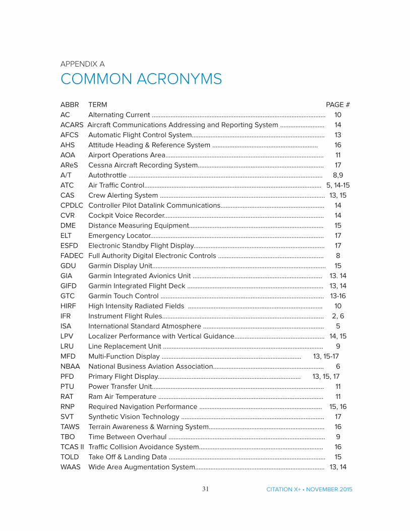
ABBR TERM PAGE #AC Alternating Current …….………….……............................................................................ 10ACARS Aircraft Communications Addressing and Reporting System …….................... 14AFCS Automatic Flight Control System…………....................................….............………….. 13AHS Attitude Heading & Reference System …….....................…................……………. 16AOA Airport Operations Area…………………………..............................……...........……………. 11AReS Cessna Aircraft Recording System…………….............................................……….…. 17A/T Autothrottle ……………………………………….................................................................…. 8,9 ATC Air Traffic Control……………………..........................................................................…... 5, 14-15CAS Crew Alerting System ……...………….............................…………............………………….. 13, 15CPDLC Controller Pilot Datalink Communications……………………….................................. 14CVR Cockpit Voice Recorder……………………………………………........................................... 14DME Distance Measuring Equipment…………………………................................................. 15ELT Emergency Locator………………………………………......................................................… 17ESFD Electronic Standby Flight Display………………........................................................... 17FADEC Full Authority Digital Electronic Controls ………………............................................ 8GDU Garmin Display Unit……………………............................................…………………...….…… 15GIA Garmin Integrated Avionics Unit …………………....................................………..…….. 13. 14GIFD Garmin Integrated Flight Deck ………………………….......................................…….…. 13, 14GTC Garmin Touch Control ………………………….…………............................................….….. 13-16HIRF High Intensity Radiated Fields ………………………………......................................….. 10IFR Instrument Flight Rules…………………………………….………........................................... 2, 6ISA International Standard Atmosphere …………………….….…...................................…. 5LPV Localizer Performance with Vertical Guidance……..............................…………….. 14, 15LRU Line Replacement Unit …..…………….......................................................................... 9MFD Multi-Function Display ………..….................................................……….….….. 13, 15-17NBAA National Business Aviation Association………………….......................................….. 6PFD Primary Flight Display………………………......................................................... 13, 15, 17PTU Power Transfer Unit…………............................................................................……….... 11RAT Ram Air Temperature ……………………………..…………...........................................……. 11RNP Required Navigation Performance ………………...................................................... 15, 16SVT Synthetic Vision Technology ……………………..………..........................................……. 17TAWS Terrain Awareness & Warning System……………...................................……………... 16TBO Time Between Overhaul ……...……………….............................................................…. 9TCAS II Traffic Collision Avoidance System………………………………….................................. 16TOLD Take Off & Landing Data ……….…….…........................................................................ 15WAAS Wide Area Augmentation System……………….......................................................… 13, 14