specialists for conveyor and chain wheels · and tempered steel according to din 17200 due to being...
TRANSCRIPT

Specialists for
Conveyor chains and chain wheels

IWHTable of Contents
Our Company
Our Products
Our Expertise
4 The Basics4.1 Structure of a Conveyor Chain
4.2 Lubrication of a Conveyor Chain
4.3 Chain Drive Kinematics
5 The Technical Dimensioning5.1 Calculation Parameters
5.2 Types of Conveyor
5.3 Total Mass of the Material to be conveyed
5.4 Load Carrying Capacity of the Rollers
5.5 Coefficients of Friction
5.6 Calculation of the Total Tensile Force of Chain F
5.7 Calculation of the Chain Breaking Load F6 required
5.8 Calculation of the Driving Power P
5.9 Calculation of the Articulation Sur-face Pressure P"6
5.10 Examoles of Calculation
6 Dimension Tables - according to DIN
6.1 Conveyor Chains, DIN 8165 and similar, Fixing Brackets, Rollers
6.2 Carrying Chains with raised Link Plates, DIN 8165
6.3 Conveyor Chains, DIN 8167/8168, Fixing Brackets, Rollers
6.4 Carrying Chains with raised Link Plates, DIN 8167
6.5 Trough Conveyor Chains, DIN 8'165/8167 and similar
6.6 Fork Chains
6.7 Bush Chains
lllustrations of Chain Types
How to find us
How to contact us
Page
h
8
8
10
14
14
15
15
17
18
20
20
20
21
24
24
32
ö+
40
50
54
56
5B
60
60

Our Company
. =ll!v:..,
ZERTIFIKATDie TÜV CERT-Zertlf izierungsstelle
des Tuv Hessenbescheinigt gemäB TUV-CERT-Vedahren.
dass das Unternehmen
ETnllfn,lll?Ef nn-iilff i]\h L\ j 3 i!- r:r!i : J l- V rot**n
Karl Jungbluth Ketlenfabrik GmbH & Co.KGD.36251 Bad Hersfeld
ein Qua itätsmanagementsystem füf den folgendenGe tungsbereich eingefÜhd hat und anwendet:
H.ßterrung lnd vetui.b vonFöd.r und Gel..tk.nen. K.t.nin
Sond.EusEhtun9, Kedenrad.r
Durch en Audil g6fchr Nr 4072 2346wurde derNachweserbrachl. dass de Foderuncen der
DIN EN ISO 9001 :2000adürts nc D'e6eszedlkär il!Jro b s okrober2oos
Erslzennz erungzedi,karR€orsi6rN' 73 100 1064
!n =:-fr-'-'F;l.;Eiar.i::::i;
Headquafters and production at our location in Bad Hersfeld - certified according to DIN EN ISO 9001:2000
For more than fifty years now, the name Jungbluth Förderketten (conveyor chains) has stood for exper-tise and quality in the production of chains and chain wheels. Our products are used in the steel, auto-mobile, mining, wood-working and building material industries, in foodstuff production, recycling plants,power stations and in many other fields of application.
Our customers'satisfaction is our highest aim. Providing competent and comprehensive advice to ourcustomers during the preparation and implementation of projects is an essential task for us. Our teamof engineers and technicians is always available to give you support in calculating and designing chaindrives. We can also advise you on suitable materials and good environmentally-friendly lubricants.
We produce our wide range of conveyor chains and conveyor wheels at our location in Bad Hersfeld,using state-ofthe-art machinery and highly qualified staff. All essential steps in the chain productionare performed at our company. Our extensive machinery includes CNC machining centres, CNClathes, presses (up to 400 t), welding robots, our own toolmakers' shop and thermal treatment facili-tia e
ln both the selection of materialand the outsourcing of pro-cesses (e.9. special thermalprocesses) we cooperate ex-clusively with certified, long-standing, reliable partners.
Our certified quality manage-ment system and thorough tes-ting after each work step gua-rantee the high quality of ouroroducts. CNC machining centres in our second plant
-3-

Our Products
As our product range is mainlyfocussed on made-to-orderchains, your special require-ments are our standard lines.Our products are manufacturedaccording to your particulars,but in addition we also developnew optimised drive solutionsfor your individual applications.
We are able to provide almostall types of conveyor chainscurrently in demand.
Furthermore we supply conve-yor chains according to DINand ISO standards.
Chain wheels and customisedaccessories for chain drivesrouno up our range.
Depending on your require-ments we can supply yourchains in normal, high/low tem-perature resistant or corrosionresistant steel.
For use in unfavourable condi-tions we can offer you solutionswhich reduce chain wear andextend the lifetime of conveyorchains.
Furthermore we supply main-tenance-optimised chains forapplications where lubricationis very difficult or even impossi-ble, or where the use of lubri-cants is undesirable for envi-ronmental reasons, or becauseof the sensitivity of the materialto be conveyed.
Drawing bench chain
WHDouble-row hook chain
p=25Q
Plate chainp=450
Bush conveyor chainwith driver dog
-4-

fl- -t\l Gta-l - -T=Erl'-/ :/tLl\:__a _-\: _ L -l
Förderketten
. Conveyor chains accord-ing to DIN 8'165 or 8'167
. Trough conveyor chains
. Fork chains
. Plate link chains
. Pinions
. Steel ladder chains withbearings (liftchains forweir systems)
Production and Delivery Programme
. Bush chains according toDrN 8164
. Block chains
. Articulated racks
. Reversing chains
. Scraper chains
Pusher chains for under-floor conveyors
Drag chains
. Outboard roller conveyorchains according toDIN 8156 and 8157
. Link conveyors
. Coil transport chains
. Biplanar chains
. Apron conveyors
. Chain wheels, milled andlathed parts, punchings
;F*.?=4_!,u].a,,

YWH3 Our Expertise
Consultation & Engineering
Jungbluth Förderketten is more than just a manufacturer of conveyor chains. We see our role as our
customers' expert engineering partner for the field of conveyor chains. We accompany you from the
project planning phase, through the production and assembly stages right up to consultations on-site
where the chain is in use. On request we can check the condition of existing chains and offer com-prehensive technical advice on necessarv measures to be taken. We consider this as an indis-
pensable part of the service we offer.
Screenshots of CAD drawinqs
In order to produce optimal chain drives we rely on a constant dialogue with our customers for the
further development and design of our chains. Over the course of the years we have developed com-prehensive solutions for a great variety of applications, for example our maintenance-optimised chainswhich do away with the need for environmentally damaging lubricants and preservatives. These chains
do not only serve to protect the environment, but also result in improved cost efficiency. There are
neither any costs for lubricants, maintenance work or waste disposal, nor are there risks of fire or
conveyor down-times. Our service does not come to an end with the delivery; our engineers and tech-
nicians are always on hand to provide support when the conveyor is in operation.
Material Selection and Quality
To ensure that the conveyor chains function properly and achieve a long lifetime it is essential that suit-
able and high-quality materials are used. The material selection is preceded by the determination ofthe loads acting on the conveyor chain and by examining the conditions of operation. We have vast
experience in the selection of materials, particularly for extreme operation conditions, in corrosivemedia as well as at high temperatures ranging up to 900" C.
Our company acquires all materials exclusively from long-standing and reliable partners.Furthermore we subject the matedal to strict quality controls on reaching the company, before it isapproved for use in our production.

W,,HPrecision in Production and Quality Assurance
,,Made by Jungbluth" - the very highest quality is guaranteed because we ourselves manufacture the
oroductsl
In addition to the seleciion of the materials, the precise manufacture and careful assembly of the indi-
vidual parts of the conveyor chain determine its function, wear and lifetime. That is why we insist on
carrying out all the main production processes at our company, We only involve outside specialists
when we require special thermal processes or sudace refinement.
Production of parts at our company
The machining of material on state-of-the-arl CNC centres ensures that the even the strictest tole-
rance requirements are met. This way the essential quality features of a conveyor chain, a high piich
accuracy, exact drive-fit connections and a precise articulation clearance between pins and brushes are
guaranteed, resulting in correct functioning, low wear and a long lifetime.
The subsequent assembly of the conveyor chain is carried out by qualified specialists and is subjected
(like all previous production processes) to the thorough testing which accompanies our production pro-
Following the Jungbluth conveyor chain development and production system, characterised by a
tight pooling of application, design and manufacturing know-how, we provide expertise from the design
phase up to on-line operation in your company.
-7 -

YW*H4
4.1
The Basics
Structure of a Conveyor Chain
External link lnternal link
External link plate
Fig. 1: Structure of a conveyor chain
Link plates
Pins
Bushes
Small rollers
Large rollers /collar rollers
Pushing /Fastening links
Bush Roller Internal link olate
are made of steel according to DIN 17100 or D1N17200 with a minimumtensile strength of 600 N/mm", or of stainless or heat-resisting steel. Thesurface is strain-hardened by shot-peening to increase the endurancestrength. lf necessary, a thermal treatment and / or a surface refinementis carried out.
are made of case hardened steel according to DIN 17210 or of quenchedand tempered steel according to DIN 17200 due to being subject to wear,bending and shearing-off. To achieve a high surface hardness and a hightoughness of the pin core, the pins are additionally heat-treated, applyingthe procedures of case hardening, quenching and tempering, andboundary-layer hardening.
are subject to wear, bending and surface pressure. As material, mainlycase hardened steel is used. Like the pins they are heat-treated toimprove their material properties.
are subject to wear and shock. They are made of case hardened orquenched and tempered steel with a corresponding heat treatment.
are subject to high wear. They are made of case hardened steel or ofboundary-layer hardenable quenched and tempered steel. Normally, therunning surface is hardened. The bearing surface is either hardened, orplain bearings or rolling bearings are used. As plain bearings, especiallywear resisting bushes, porous bearings, low-maintenance plain bearings,plastic bushes, etc. can be used. As rolling bearings, mainly deep grooveball bearings, cylindrical roller bearings, or needle roller bearings areused. Plain and rolling bearings are also used if the tensile force of theconveyor chain has to be maintained as low as possible.
are chain links to which fastening or pushing elements are bolted orwelded on. They are also produced as compact parts. The shape of theseelements depends particularly on the type of the material to be conveyed.
'i\ ii'^\7,-- [l!4
-8-

YTJUNlGBLUTh]V
-
Foroerxerren
lf the chain is rntended to be used in extraordinary conditions, such as high or low temperatures, water
or aggressive media, we select the best suited materials for the construction of ihe individual parts of
the conveyor chain. In the production of our conveyor chains we direct our greatest attention to three
important quality features:
. High pitch accuracy to ensure perfect engagement conditions between chain and
chain wheel,
. Exact drive-fit connections between pins and link plates, or bushes and link plates, to
ensure the resistance against laterally acting forces to be as
great as Possible,
. Exact articulation clearance adapted to the application, as a prerequisite for low wear and
tear and a long lifetime.
4.2 Lubrication of a Conveyor Chain
The links of a conveyor chain are connected with each other by means of pins and bushes (articula-
tion elements). When the chain is guided round the chain wheel, an oscillating movement is produced
between pin and bush, leading to energy loss, wear and disturbing noise. These unpleasant side
effects, which also have a neguiiu" influence on the lifetime, are counteracted by a lubrication adapted
to the ooerational conditions. At the same time the corrosion of the conveyor chain is minimised' The
conveyor chains delivered have been provided by the company with a first lubrication and protection
againit corrosion. lt is essential that the user relubricates the chain regulary'
The user should also take into account that the cleaning of the chain depends on the lubrication
method. After cleaning you must ensure that there is still sufficient corrosion protection.
Conveyor chains can be constructed in such a way that regreasing can be carried out through lubrica-
ting nipples and bore holes. Also automatic lubrication systems are common in transporting plants with
"oiu"yo, chains. They have the advantage that unexpected dry-running is avoided and an optimal
dosage of the lubricant is possible'
The selection of the chain lubricant depends on the operating conditions of the transporting plant and
the reouirements of the material to be conveyed. The main features for the selection of a suitable lubri-
cant are:
. Ambient temPerature
. Strain on chain conveyor
. Conveying speed
. Aggressiveness and state of aggregation of the surrounding media
. Abiliiy to run after failure of lubricant supply
. Suitabilitv for the intended lubrication method
-9-

4.3 Chain Drive Kinematics
4.3.1 Polygon Effect
When the chain is turning round the chain wheel, speed variations are produced due to the factthat the chain does not describe the circuit of the pitch circle, but forms a polygon. lt movestowards the centre of the chain wheel causing a chain speed reduction, while rotation remainsuniform (polygon effect).
-t-f"l I
I ol-li
Vmin =
on the Number of Teeth
\/ _ do.n n [m-l"max -60 iooolsl
4.3.2 Speed Variations in Dependence
I
s;oE
äE0)0)
a
Number of teeth +Fig. 3: Speed difference in dependence on the number of teeth
Conveyor chains with rollers running externally allow the chain to be guided on both sides up tothe middle of the chain wheel, by which a 50% reduction of the speed difference can beachieved. This means that the run-in speed of the chain link into the chain wheel toothspace isdelayed to zero and that the run-in noise is reduced.
Fig. 4: Measures to reduce the speed difference
-10-
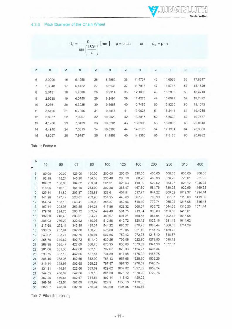
4.3.3 Pitch Diameter of the Chain Wheel
oo = --=!- [mm]sinrql -
\z )
p = pitch
6
7
8
I10
11
12
13
14
15
n
2,0000
2,3048
2,6131
2,9238
3,2361
3,5495
3,8637
4,1786
4,4940
4,8097
z
to
17
'18
19
20
21
22
23
z4
25
n
5,1258
5,4422
6,0755
6,3925
6,7095
7,0267
7,3439
7,6613
7 o7P.7
1 00,00 126,00 160,00
115,24 145,20 184,38
130,65 164,62 209,04
146,19 184,19 233,90
161,80 203,87 258,88
177,47 223,61 283,96
1 93,18 243,41 309,09
208,93 263,25 334,28
224,70 283,12 359,52
240,48 303,0'1 384,77
256,29 322,92 410,06
272,11 342,85 435,37
287,94 362,80 460,70
303,77 382,75 486,04
3'19,62 402,72 511 ,40
335,47 422,69 536,76
351,33 442,68 562,13
367,1 9 462,66 587 ,51
383,06 482,66 612,90
398,93 502,65 638,29
414,81 522,66 663,69
430,69 542,66 689,1 0
446,57 562,67 714,51
462,54 582,69 739,92
478.34 602,70 765,34
26 8,2962
27 8,6138
28 8,9314
29 9,2491
31 9,8845
32 10,2023
33 10,5201
34 10,8380
35 '1 1 ,1 558
36 11 ,4737
37 11 ,7916
38 12,1096
39 12,4275
40 12,7455
41 13,0635
42 13,3815
43 13,6995
44 14,0175
45 14,3356
56 17,8347
57 18,1529
58 18,4710
59 18,7892
60 19,1073
61 19,4255
62 19,7437
63 20,0618
64 20,3800
65 20,6982
Tab. 1: Factor n
p40
z
6 80,00
7 92,19
I 104,52o 11A Oq
10 129,44
11 141 ,98
12 154,54
13 167,14
't4 179,76
15 192,38
16 205,03
17 217,68
18 230,35
19 243,02
20 255,70
21 268,38
22 281,06
23 293,75
24 306,45
25 319,14
26 331,81
27 344,55
28 357,25
29 369,96
30 382,67
125100
200,00 250,00 320,00
230,48 288,1 0 368,76
261 ,31 326,63 418,09
292,38 365,47 467,80
323,61 404,51 517,77
354,95 443,68 567,92
386,37 482,96 61 8,1 I417,86 522,32 668,57
449,40 561,75 719,04
480,97 601 ,21 769,55
512,58 640,72 820,12
544,22 680,27 870,75
575,88 719,85 921,40
607,55 759,43 972,08
639,25 799,06 1022,80
670,95 838,68 1073,52
702,67 878,33 1124,27
734,39 917,98 1175,02
766,13 957,66 1225,80
797,87 997,33 1276,59
829,62 1037,02 1327,39
861,38 1076,72 1378,20
893,14 1116,42 1429,02
924,91 1156,13 1479,85
956,68 1 195,85 1530,68
400,00 500,00
460,96 576,20
522,62 653,27
584,76 730,95
647,22 809,02
709,90 887,37
772,74 965,92
835,72 1044,65
898,80 1123,50
961,94 1202,42
1025,16 1281,45
1088,44 1360,55
1151,76 1439,70
1215,10 '15'18,87
1278,50 1598,12
1341,90 1677,37
1405,34
1468,78
1532,26
1595,74
1659,24
1722,76
v
ds =p.h
47 14,9717
48 15,2898
49 15,6079
50 15,9260
51 16,2441
52 16,5622
54 17,1984
55 17.5166
315 400
630,00 800,00
726,01 921,92
823,12 1045,24
920,99 1169,52
1019,37 1294,44
1118,09 1419,80
1217,06 1545,48
1316,25 1671,44
1415,61lAtq nq
1614,62
1714,29
fab.2'. Pitch diameter d6
-11

v4.3.4 Toothing of Chain Wheels
,/
Fig. 5: Toothing of chain wheels
p = Teilung g = Laschenbreite
d = Buchsen- oder Rollendurchmesser
do = Teiledurchmesser
dr = Kopfkreisdurchmesser
4 =Fußkreisdurchmesser
siehe Tabellen
,- P
'o - sin (19O, ")
dx=do+0,25'ddx=do+ 0,5'd
dt =do-d
oder do = p'n
+10fürd<70+6 fürd>70
nach Wahl - siehe Tabellen
dN,n* = rnax' Nebendurchmesser
u = Zahnlückenspiel
ri = Zahnfußradius
rr. = Zahnkopfradius
ö = Hilfswinkel
z =Zähnezahl
dN,"" = oo'"o"(1m')a,, n
u = 0,2'd+Q'05'P+5
u = 0,04 ' p für gegossenes Profil
t = 0,515'd fürd < 70
rr =0,51 'd fürd>70
rr = 0,8'P-rr
6 = (rao"-rOO, ) ro
-12-
z >6nachWahl

4.3.5 Chain Length L, Distance between Axes a
The chain length L is calculated by multiplying the number of chain links x by the chain pitch p
L=x.p
With an equal number of teeth of the chain wheels and the assumed distance a between the axes, thefollowing applies:
x=2.?+zp
With a different number of teeth of the chain wheels.
x=2.a +21+22 *(zz-+\.9p 2 [ 2.n )a
applies.
In the case of endless chains, the number of chain links has always to be rounded up, selecting an evennumber, if possible, in order to avoid offset links.
Fig. 6: Distance between axes
The exact distance between axes is calculated as follows:
-13-
Y
-/
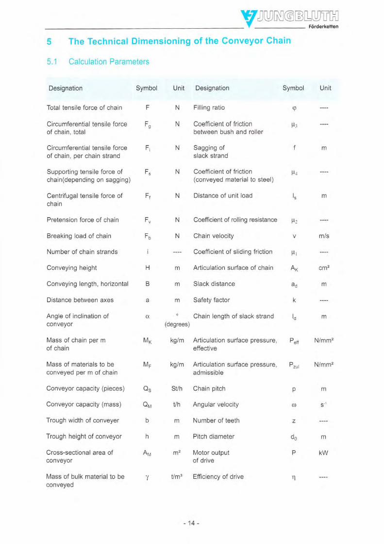
The Technical Dimensioning of the Conveyor Chain
Calculation Parameters
Designation
Total tensile force of chain
Circumferential tensile forceof chain, total
Circumferential tensile forceof chain, per chain strand
Supporting tensile force ofchain(depending on sagging)
Centrifugal tensile force ofchain
Pretension force of chain
Breaking load of chain
Number of chain strands
Conveying height
Conveying length, horizontal
Distance between axes
Angle of inclination ofconveyor
Mass of chain per mof chain
Mass of materials to beconveyed per m of chain
Conveyor capacity (pieces)
Conveyor capacity (mass)
Trough width of conveyer
Trough height of conveyor
Cross-sectional area ofconveyor
Mass of bulk material to beconveyed
Unit Designation
Filling ratio
Coefficient of frictionbetween bush and roller
Sagging ofslack strand
Coefficient of friction(conveyed material to steel)
Distance of unit load
Coefficient of rolling resistance
Chain velocity
Coefficient of sliding friction
Articulation surface of chain
Slack distance
Safety factor
Chain length of slack strand
Articulation surface pressure,effective
Articulation surface pressu re,
Symbol
F
F"
q
fr:
lLt
Fi
FS
Fz
V MiS
N
N
N
N
admissible
SVh Chain pitch
Vh Angular velocity
m Number of teeth
m Pitch diameter
m' Motor outputof drive
Um3 Efficiency of drive
Symbol Unit
!Lr
AK cm2
3'6m
k ----
to fll
Per N/mm'
Pzul
p
0)
z
do
P
n
Nimm'
Ff
FV
F,'o
i
H
B
a
Ct
MK
MF
QS
QM
n
n
Ap4
v
m
m
(degrees)
kg/m
kg/m
m
s-r
m
KW
-14-

5.2 Types of Conveyor
The conveyors are subdivided in two main categories:
. Sliding conveyor chains
. Rolling conveyor chains
They are furthermore classified according to the following arrangement criteria:
. Horizontal conveyance
. Oblique conveyance
. Vertical conveyance
. Combined convevance
5.3 Total Mass of the Material to be conveyed
This is the total mass of the material to be conveyed, which is resting and is to be moved on the
conveyor chains or on possibly existing supporting elements (plates, transverse bars, cross-rails, slatbands, etc.).
According to the load distribution on the conveyor chain, a difference is to be made between point,
individual and linear loading. lf the load is concentrated on a reduced area, the chain pins and rollershave to be recalculated concerning deflexion and pressure, respectively, when dimensioning the
conveyor chain.
5.4 Load Carrying Capacity of the Rollers
The load carrying capacity of the rollers depends on the roller material, the type of bearing, the chainvelocity, the temperature, and the lubrication. For surface-hardened steel rollers, with a low chainvelocity (< 0,25mls) and a sufficient surface pressure, up to 800 N/cm'?are admissible.
lf rollers are made of quenched and tempered or of unhardened steel, of grey cast iron or ofsynthetic material, lower bearing contact pressures are admissible (compare the following tables).
Advantages of synthetic rollers are:
. No maintenance
. Lightweight construction
. Silent run
. High chemical resistance
It is furthermore possible to improve ihe sliding properties of the rollers by means of bearing bushes.A suitable bearing material is lead tin bronze (surface pressures up to 300 N/cm'), but also specialbearing materials are appropriate for a low-maintenance operation.
The following tables 3a and b show admissible roller loads for conveyor chains according to DIN 8165
and DIN 8167, which have to be multiplied by the corresponding correction factors from tables 4 to 8,
using the formulae indicated:
Admissible load of the roller = table value .\ f2 f3.f 4 fs
- 15 -

Chain according to
DtN 8165
FVT 40FVT 63FVT 90FVT 112
FVT 140
FVT 180
FVT 250FVT 315FVT 4OO
FVT 5OO
FVT 630
Mating of materialBush / Roller
c15E / C15EC15E | 9SMn28E
2000
3000380051 007050
'10550
1 555021500239003120039400
Chain according to
DIN 8167
MT 20MT 28MT 40
MT 56
MT 80
MT 112
MT 160
MT 224MT 3,15
MT 450MT 630MT 9OO
Tab. 3: Loadability of rollers (N/Roller)for carrying roller chains according to DIN 8165 and DIN 8'167
Roller type
Roller
Flanged roller
Chain velocity in m/s
0,100,250,501,00
Tab.7: Factor fa : Chain velocity
Tab. 4: Factor f1 : Roller type
Lubricating conditions
Sufficient lubrication, no dirt or rough operating conditionsInsufficient lubrication, no dirt or rough operating conditionsWithout lubrication, with much dirt and rough operating conditions
Tab. 6: Factor f3 : Lubrication
Roller material (bush of case-hardened +
steel, hardened) t2
Case-hardened steel, hardened 1,00Stainless steel, hardened 0,60Stainless steel, unhardened 0,30Standard steel, unhardened 0,20Grey cast iron 0,12
Tab 5: Factor f2 : Roller material
r3
1,00,4 - 0,60,2 - 0,35
Temperature in "C
20 - 200200 - 260260 - 285285 - 300
Tab 8: Factor f5 : Temperature
alS
1,000,500,25n'i^
Max. soecificbearing contact pressure
in N/cm'
fl
1,0
0,9
t4
1,151,000,850,50
Mating of material
Roller Bush
Case-hardened steel, hardened Case-hardened steel, hardenedQuenched and temoered steel il n
Unhardened steel il il
Grey cast ironBronzePolyamide 6 " ''
Tab. 9: Admissible maximum values of specific pressing
800300tou100300
50
IW*HMating of material
Bush / Roller
c15E / C15EC15E / 9SMn28E
1 0501 350'1900
2750
38505200
7200'10050
1 35001 84502600036450
-16-

yruqqHr"H5.5 Coefficients of Friction
5.5.1 Sliding Friction of Chains on a Base in Continuous Operarron
5.5.3 Coefficient of Friction between Material to be conveyed and Steel ;.r., Bulk Weight yand Filling Ratio q
Type of materialto be conveyed
AshOreCerealsWood chipsGravelCoalCokeLoamFlourSandBroken stonePeatCement 0,05 1,20
Tab. 13: Coefficient of friction - material to be conveyed / steel, bulk weight and filling ratio
Goodlubrication
0,250,150,25
Goodlubrication
0,200,150,10
0,015 ... 0,005
FrMaterial of slide rail
SteelSynthetic materialHardwood
Tab. 10: Coefficient of sliding friction p1
bush diameterroller diameter
5.5.2 Rolling Friction of Chains on Steel Guides
lnsufficientlubrication
0,350,200,30
2.c + p3.d3Coefficient of rolling resistance p2= Pz= 0,08".0,12'.-0,18
d5
.l-v3
ds=lmmllmml
experimental coefficient,depending on material and the surface roughness of the areas of contact
Conditions of guide c
0,5 Steel roller on steel guide with smooth surface0.6 Mean value1,0 Steel roller on steel guide with rough surface
Tab. 11: Coefficient c in dependence on material and contact surface
P3Mating of material Roller / bush
Steel roller on steel bushRoller with bronze bush on steel bushPA6 roller on steel bushRoller with rolling bearing on steel bush
Tab. 12: Coefficient of friction between roller and bush u"
Insufficientlubrication
0,30
0,150,03
Coefficientof friction pa
0,851,200,500,801,000,901,00n -rE
0,500,800,650,70
Bulk weighty in Vm"
0,502,25nA60,25I -rtr
0,800,451,250,601,551,800,40
Filling ratioq
0,700,600,80n7Ä0,650,500,600,700,700,600,650,800,70
-17-
Y
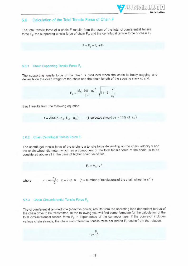
5.6 Calculation of the Total Tensile Force of Chain F
The total tensile force of a chain F results from the sum of the total circumferential tensile
force Fn, the supporting tensile force of chain F", and the centrifugal tensile force of chain F1.
F=Fn+F.+F1
5.6.1 Chain Supporting Tensile Force F"
The supporting tensile force of the chain is produced when the chain is freely sagging and
depends on the dead weight of the chain and the chain length of the sagging slack strand.
tr- M* '9,81 .aa2
ö.7
Sag f results from the following equation:
(f selected should be = 10oÄ of ao )
5.6.2 Chain Centrifugal Tensile Force F1
The centrifugal tensile force of the chain is a tensile force depending on the chain velocity v and
the chain wheel diameter, which, as a component of the total tensile force of the chain, is to be
considered above all in the case of higher chain velocities'
whereO6
v-(l).-:2
Ft =Mrv2
o = 2 .p . n (n = number of revolutions of the chain wheel in s-1)
5.6.3 Chain Circumferential Tensile Force F"
The circumferential tensile force (effective power) results from the operating load dependent torque of
the chain drive to be transmitted. In the following you will find some formulae for the calculation of the
total circumferential tensile force Fn in dependence of the conveyor type. lf the conveyor includes
various chain strands, the chain circumferential tensile force per strand F' results from the relation:
F^E_ v
' i-T
?ä6-
ao.(lo-ao)
-18-

Sliding Friction
3600 vFo = '1,1 .a . pr. 9,81.(2.M^+ M, ) QS
ls
io
Rolling Friction
Fs=1,1. a. 9,81 [(rvo*Mr)' (p.,'coso+sinu) +Mx' (plcoso(-sinu)]
if (p,,. cos cx, - sin a) < 0 :
Fs = 1,'1 a 9,81 ' (M^* Mr ) (p.r'cos tx, + sin u)
Fu=2,2'F" if H/B> P,
Fu=2,2.[r"+s,at M^ (B.r,r-H)] if H/B<p1
Fs= 1,1 . a . *2.9,81 . (2' M*+ M, ) o. = !gf-fFu= 2,2 ' (F" + a .pr2 '9,81 'M6 )
Fs= 1,1'a' 9,81 [('v^*M-)' (plcosü+ sincr)*M^' (plcosü-sina)if (pz.cos s - sin u)< 0 :
Fs= 1,1'a '9,81 ' (M^* Mr ) (p,' cos cx, + sin a)
Fu=2,2'F" tf HIB> pz
Fu=2,2.[r.+s,at M* (B pz-H) if HIB <1t,
Trough Chain Conveyor
Fs=1,1 a o,er IZ
Fu=2,2'(F.+a'p,
Mx.lrr . #i" u- )
. 9,8'1 .MK )
a .e,81 f t^ (p1 'cos a + sin "). a:t' (po'cos c' + tin o) *l
L ttl^. (pr. cos ü - sin a) I
.cos cx, - sin u)< 0 :
a. e,B1 [t^ (p,.cosa+ sin"l.ft' (po.coso*rino)]
Fn- .r r | | | r r \-
-- .:ü/---;--;--------- '
- _L_ _Fg=1'1'
if (tr r
Fs=1'1'
Fr=2,2'F, if
Fu= 2,2 ' [r, + 9,41 'M*
H/B> p1
(e p,-Fl)
-19-
if H/B < p.,
INBL"Y."T"H5.7 Calculation of the Chain Breaking Load Fo required
Fo= k 'F,
Safetyfactork k=5...2 .12
The safety factor k depends mainly on the operational conditions and the number of teeth of thechain wheel. Generallv, k is about 6 to 7.
5.8 Calculation of the Driving Power P
P = il- ; where rt = 0,75...0,8...0,91000 ''q
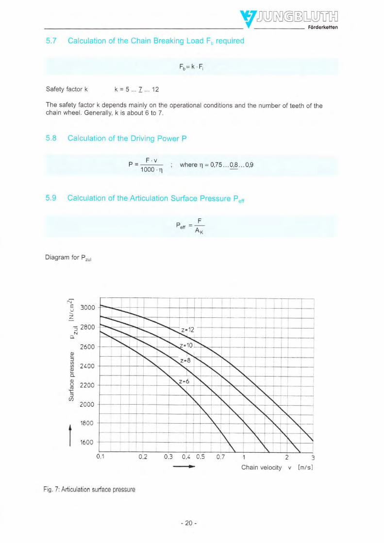
5.9 Calculation of the Articulation Surface Pressure P"n
trP"o = Ä?
Diagram for Pru,
NE "nnnLJ Jvvv
z- ?ennI 4VVvN-
2600L-fr zrcoL
9lx tzvv!a
2000
. 1800IIII
| 1600
3
lm/sl
0,3 0/. 0,5
....-..+12Chain velocity v
Fig. 7: Adiculation surface pressure
-20-

5.10 Examples of Calculation
Example 1: Trough conveyor, horizontal
Material to be conveyedConveying lengthConveyor capacityTrough width of conveyorTrough height of conveyorNumber of chain strandsNumber of teeth of chain wheel
Wood chips40m25 lh400 mm300 mm1
8
a) Calculation of the chain velocity
Qrrrr = 3600 .v 'Anr 'T
en,rv=-3600.Av .y
3600 .0.09 .0,2525 =031{.
Qu=25/n
\ = 0,25 (see section 4.5.3)
g = 0,75 (see section 4.5.3)
b=0,4mh = 0,3m
a=40m./
Mo =B*s/'' /mFr = 0,35 (see section 4.5.1)
p+ = 0,8 (see section 4.5.3)
i=1k=7
Av = b'h'tPAH,r = 0,4'0,3 '0,75
Av = 0,09 m2
b)
F^
F^
F^
Fb
=
Galculation of the chain tensile force
=1,1.a e,81 [2.Mx.u,
-f\ u.)
=1,1.40 e,81 (2.8.0,35.--?!- os)
=10150N
F^ri --l-
I
10150= P (F" and F negligible)
= k.F = 7 .10150 = 71050 N
1. assumption: Selection of the trough conveyor chain TF 90 according to table on page 50
Standard pitch: P = 125 mm
c) Recalculation of chain considering articulation surface pressure
FPer =;- < Pzrt
ÄK
p"n = !P = 2o3o Y. , .2soo y 2
Chain size TF90 selected correctly!
F = 10150 N
Ax = 5 cm2 (see table on page 50)
-zI-
Prul = 2500 /" , (.." section 4.9)

d)
F,
Fu
Fu
e)
Example 1: Trough conveyor, horizontal - continuation
Calculation of chain pretensioning force
= 2,2.(Fs + a 'Fr . 9,81 MK )
= 2,2. (o + 4o . 0,35 9,81 8)
= 2420 l,l
Driving power required
Example 2: Conveyance of pallets
Material to be conveyedConveying lengthPallet sizeTotal mass per palletNumber of chain strandsChain velocityNumber of teeth of chain wheelMax. number of palletsChain type selected
a) Calculation of the chain tensile force
Fs = 1,1 .a.Fz .9,81 .(2.M^ + M. )Fn = 1,1'30 .0,12 9,81 (2 . 11 + a00)Fn = 16409 I
P= F'v1000.q
n 10150 .0,31l- = ----- = 3.9 kw
1000 , 0.8
=?= ry=82ogx
= k.Fi
=7.8200 =57400 N
F = 10150 N
v = O,g1%
I=0,8
Pallets30mLength: 1200 mm, width: 800 mm600 ks20,2 m/s1020Carrying roller chain according to DIN 8165
Fi
Mx =2 u5%=,,r/^
Mr=20 St. 600 k/.
/ ptece
30tFb
trrb
Yreq.Y"TH
F, = 0 (as slack strand is supported)
a=40m
Mn =Brn/'- / m
ltr = 0,35 (see section 4.5.1)
a=30mFz = 0,12 (estimated, see section 4.5.2)
Vir = a00 k/,.
k=7
= Selection of the chain type FW 63, with a minimum breaking load of 63 kN (see table on page 44)
-22-

VJUrygqL"V.T"H
Example 2: Conveyance of pallets 'continuation
b) Recalculation of chain considering articulation surface pressure
P"o =*<P.u,Fi = 8200 N
Ar = 3,7 cm2 (see tables on pages 44 and 45)
Pzur =2780 / , lseesection 4.9)
c) Recalculation of roller load
Number of carrying rollers : 4
Chain pitch : 100 mmPallet mass : 600 kg
r"n = 93P =2220 Y"^r=2780 y ,
Existing roller load
Admissible roller load
Carrying roller chain FVT 63
- 600 '9'81 =1472 V .. = lsoo V .,4 ____JJ9!et _-----/--!9tte!
: see section 4.4
: 3ooo V t, f2.\.'14 fs,/ rollel
- Roller
- Case-hardened steel, hardened
- Insufficient lubrication, no dirt or rough operating conditions
- Chain velocity = 0,2 m/s
- Ambient temperature 10 - 25 "C
d) Driving power required
F^ .vP- "1000.n
P _ 16400 0'2 = 4,1 kW
1000 . 0,8
f1 : 1,0
f2: 1,0
f3 : 0,4...0,6
fn:1.0f5 : 1,0
+ Admissible roller load = 3000 Yor.,.1,0'1,0 .0,4.1,0 .1,0 =1200 /o,,.,
+ Existing roller load = 1500 Yot",, 1200 Yo,,",
In dependence of the chain lubrication (factor f3), the admissible roller load may be exceeded. lt istherefore more reasonable to select the next chain in size. + FVT 90
Fs = 16400 N
v =0,2*I=0,8
-23-

6 Dimension Tables
6.1 Conveyor Chains, DIN 8165
Conveyor chains with solid pins Type FV
Single-strand chains
Pitch
DIN 8165 part 1 Sheet 1/2
Rollers Flanged Link plate Link platerollers width thickness
aad5 d6ld7 g s
32 40148 26 3
40 50/60 30 4
63t73
72t87 40
OU 80/95
1001120 50
80 125t145
60
60 100 150/185
90 1401170 70
70
80110 160/195
DINnumberof chain
FV 112
FV 140
FV 180
FV 250
FV 315
FV 4OO
FV 5OO
10
12
12
48
5Z
36
+z
50
70
22
26
30
42
44
50
to
18
20
30
32
18
22
25
30
JC
55
65
70
BO
p
40OJ
100
63100125160
63100125160200250100125160200250
100125160200250315
125160200250315400
125160200250315400
160200250315400
160200zcv315400
160200250315400500
200250315400500
FV 40
FV 63
lnsidewidth
b1
Pins
od1
10
12
14
Bushes
ad3
15
18
20
Smallrollers
adn
mm
20
26
L---p .*
FV 630 90 56
-24-
80 120 1701210 100 12

IConveyor chains with solid pinsSingle-strand chains
Type FV
Articula- Admissi-tion ble articu-
surface lationsurface
pressure
DIN 8165 part 1 Sheet 2i2
Weight of chainMax.rivet pinlength
Breakingload
KN
40
DINnumoerof chain
FV 40
FV 63
FV 90
Max.projectionof closing
pinK
mm
4,5
4,5
withwrtnout.. small
roilerroiler
a 4a
2,431,99
withrargeroller
kg/m
4,713,442,62
withflanged
roller
37
cm'
3,7
5,0
N/cmt
2680
2840
3000
2,70z, to1,82
3,522,912,712,53
FV 140
FV 180
FV 250
FV 315 117
10,0
B,O
FV 400 131
FV 112 63 2750
2720
18,7 2230
30,7 2170
38,2 2180
elez8,447,20o,J I
15,2812,9810,969,53I 4.7
20,1616,9714,1912,2010,619,29
31,4425,9422,0118,8616,2714,14
o,ö
8,6
I Z,J
112
140
180
6,0
7.0
5,284,344,03
6,17
5,274a.74,73
7,616,94
5,92
A ?I
10,78oanona
9'RI
14,7813,1912,0611 ,1610,41qRn
20,3818,5017,00'1F.'7F'
14,75
24,2722,0520,2818,8117,62
30,4027,3424,88zz,öo21 ,2010 0A
36,9633,3430,3427,9026,09
4,21
3,062,80
5,064,604,193,903,67
7,116,44
E AA
5,10
8,877,947,13
AnoF.71
12,61t l,zJ10,24q454708,26
17,9216 A614,0312,7311 ,6610,78
24,8422,0719,8518,0216,53
28,6225,5323,0621 ,0219,36
4,62227
6,04 8,354,50 5,963,98 5,143,52 4,43oAl7i7o,z I
4,914,48
10,609,238,047'lA
11 6510,03
714,to 1c16,3614,3412,7311 ,4010,31
27,7523,33 43,0920,17 35,9817,65 30,2915,56 25,6013,85 21,76
35,4430,55 55,0226,64 46,2123,41 38,9420,77 33,00
44,4638,21 67,9533,20 57,0029,07 47,9625,70 40,57
57,7549,21 85,7142,38 71 ,5936,75 59,9232,14 50,3928,73 43,33
66,2456,76 92,7448,93 77,4942,54 65,0337,E0 55,79
8,0
315
FV 500 141 37,6133,1 1
29,5026,5224,0922,29
45,8240,4235,9732,3329,63
2160
10,0
FV 630 153 10,0 630 48,7
-25-

_vzuN9qr"v_T"HFixing Brackets for conveyor chains Type FV DIN 8165 part 2 Sheet 1/1
DINnumberof chain
FV 40
FV 63
FV 90
FV 112
FV 140
FV 180
FV 250
FV 315
FV 4OO
FV 5OO
Length ofbracket
l2
30
Co4050
3040506065
3040506580
3040506580
100
35506580
100100
so6580
100100
;-oc80
100100
;OUBO
100100
^"80
100100100
io100100100
3150
40506070
506070BO85
50657590
105
55657590
105125
658095
110130130
50BO95
110130130
5095
110130130
50100120140140
90120140140140
50110140140140
63100
bJ100125160'100125160200250100125160200250100125160200250J IC
1251602002503'15400
125160200250315400
160200250315400
160200250315400
160200250315400500
200250
400500
9,0
r+,;t'Z)
Hole Distancebetween
holes centresdfr
mm
6,6 50
9,0 68
't1,0
11 ,0
17,5
47F.
Overall Height Bracketwidth of above chain DIN 1028chain centre
f2 (max) h
100
110
130
140
170
20 25x25x3
30 30x30x3
40x40x4
40x40x5
50x50x5
50x5OxG
65x65x7
70x7lx9
80x80x1 0
80x80x1 0
100
100
1901284? Ä
138
170
190
13,5
230
300
FV 630
-26-
zJu 350 1 00x1 00x1 0

Rollers for conveyor chains DIN 8165
Small rollers
Shape ALarge rollers
Shape B
DtN 8166
Flanged rollersShape D
Sheet 1/1
Weight
Roller Flangedroller
kg
0,081 0,167
0,160 0,322
0,274 0,579
0,444 0,946
0,591 1,349
1,052 2,732
2,415 7,950
3,248 9,732
4,396 12,733
DrN Widthnumberof chain b4 bs b7
Shape C
b8 d3 da
zz,z
zo,z
Diameter
d5 d6 d7 de
max" max. max. max. max. max. max. max. max.
mm
FV 40
FV 63
FV 90
FV 112
FV 140
FV 180
FV 250
FV 315
FV 4OO
FV 5OO
FV 630
12,0
15,0
18,0
21,5
zc,v
60
IJ
87
95
50
OJ
72
80
40
48
55
15,1
18,1
zv, I
3,0
4,0
4,0
5,0
17
21
34,0 6,5 30,2
40,0 8,0 36,2
150
160
100
110
120 50
145
170
185
60 1,625
7048,0 10,0
52,0 10,0
57,0 12,0
62,0 14,0
42,2
44,2
50,2
56,2 80
-27 -
Shape E
72
120 170 210 5,882 16,575

v
Type FV DIN 8165 part 1 Sheet 1/2Conveyor chains with solid pins
Double-strand chains
without rollers
with small rollers of form A according to DIN 8166
Sp
I L"g -l
DINnumberof chain
FV 40 MELW
FV 63 MELW
FV 90 MELW
FV 112 MELW
FV 140 MELW
FV 1BO MELW
FV 250 MELW
FV 315 MELW
FV 4OO MELW
FV 5OO MELW
FV 630 MELW
250
256225
257218
z3J213
260205
262202
270,lol q
273184
279172
315
321290
322283
324278
325270
327267
335256,5
338249
344ZJT
348227
350219
Track widthmm
400 500
406 506375 475
407 507368 468
409 509363 463
410 510355 455
412 512352 452
420 520341,5 441,5
423 523334 434
425 529322 422
433 533312 412
435 535304 404
294 394
_28_
OJU
636605
637598
639593
640585
642582
650F.71 F
653564
659552
663542
665534
665524
800
807768
809763
810755
812752
820741 ,5
823734
829722
833712
835704
835694
1000 1250
-_: ___
1 009963
1010 1260955 1205
1012 1262952 1202
1020 1270941 ,5 11 91 ,5
1023 1273934 1184
1029 1279922 1172
1033 1283912 1162
1035 1285904 1154
1035 1285894 1144

Type FV DIN 8165 part 1
with runners of form B and C accordino to DIN 8166
with flanged runners of form D and E according to DIN 8166
Conveyor chains with solid pinsDouble-strand chains
Sheet 2/2
DINnumberof chain
FV 40 MELW
FV 63 MELW
FV 90 MELW
FV 112 MELW
FV 140 MELW
FV 180 MELW
FV 250 MELW
FV 315 MELW
FV 4OO MELW
FV 5OO MELW
FV 630 MELW
Track widthmm
1400 1600
-----:
:__:-:
1420 16201341,5 1541,5
1423 16231334 1534
1429 16291322 1522
1433 16331312 1512
1435 16351304 1504
1435 16351294 1494
Axis Axisga
d1 d8mm mm
10 15
Sp 1 800
--:
18201741,5
18231734
18291722
1 8331712
1 8351704
1 8351694
2000
:::
::_
20201941,5
20231 934
20291922
20331512
20351 904
20351 894
mm
1,0
1,5
3,0
2n
3,5
tI
mm
1n
(n
6,0
10,0
11 ,5
1^ F
16,5
17,5
17,5
18
20
22
26
30
Jb
1Z
50
'16
18
20
26
32
2,5
3,5
3,5
12
-29-
4,5 42 56

Conveyor chains with hollow pins
YTJUNGBLUTH- V
-
Förderketten
Type FV similar to DIN 8165 part 1 Sheet 1/2
DINnumberof chain
FV 40
FV 63
FV 90
Pitch lnsidewidth
b1
SmallroIters
ad4
mm
20
26
30
Hollow Bushesptn
aad8/d1 d3
6/10 15
8t12 18
10t14 20
2210/16
Rollers Flanged Link plate Link platewidth thickness
gd5
rollersg
d6/d7
4
10
12
26
30
63t73
4A72187
80/95
Än
60
70
48
32
36
42
50
ou
OU
30
18
22
25
30
1211835
14t2445
4063
100A?
1öö125160
63100125160200250
100125160200250
100125160200250315
1251ä0zvv250315400
125160200250
400
160200250315400160200250315400
160200254315400500
200250315400500
32 40148
4A 50/60
FV 112
FV 140
FV 180
FV 250
FV 315
FV 4OO
FV 5OO
18t26 36
65
70
80
20t30
22t32
42
50
70 100fi20
80 1251145
90 1401170
100 150/185 70
TO 110 160/195
FV 630 90
26t36
56
-30-
80 120 1701210
80
12

YTJUNGBLUTHV Förderketlen
Conveyor chains with hollow Pins Type FV similar to DIN 8165 Part 1 Sheet2l2
without withroller small
roller
4-,523,30
8,11Ä R,l
5,024,34
3B
12.98 19,6311 ,23 16,559.70 13,868;61 11,e47.74 10,407 ,01 9,13
42,0135,1 1
29,6025,05zt,öz
53,7245,1838,1232,36
54,4146.55 83,0540,25 69,4535,06 58,2330,81 49,0627,66 42,26
27,0724,6722,7521 ,1719,871C Ol
33,1330,2727,9125,9924,56
3.97 5,803,20 4,352,94 3,862,71 3,43
3,282,762,592,1ö
4,844,073,80
3,41aaa
5,84
5,064,804,60
7,096,526,025,66
5,14
N/cm'
2000
1 700
1 500
1 650
5,984,784,384,023,76
6,786,18
5.274,97
8,347,526,816,29
5,54
11,871N AA
9,07
8,03'16,5314,5613,1612,0311,1010,35
23,2220,7818,8217,2015,88
26,4123,7721 ,6519,91'18,48
34,2830,4427,36?1,91zz,tozt,zz41,99
30,4128,10
cmt
2,5
4.7
5,0
1 8006,8
8,6854,0
96 12,3 1 300 1q,q49,228,638,167,777,45
148018,7
30,7
5,0
6,0 1370
1 390
==-I-l- + ölD)DIN Max.
number rivet Pinof chain length
d
FV 40 34,6 3,5
4,0
FV 63 43,0
FV 90
FV 112 59,5
FV 140 64.5
FV 180 84,0
FV 250 94,0
FV 315 112,0
FV 400 125,0
FV 500 135,0 6,0
Max. Breakingprojection loadof closing
ptn
K
mm kN
aF^
25,8
292 38,2
Articula- Admis-tion sible arti-
surface culationsuface
pressure
tF42,064 7q
.t2 2012,1111,1910,46oAA9,36
18,7617,21,1A OA
14,9414,10
22,0620,2918,8717,7016,74
Weighi of chain
kg/m
2,96 4,542,33 3,331,92 2,55
with withlarge flangedroller roller
9.176.79 9,595,98 8,225,28 7,024.77 6,174"37 5,48
10,27 14,958,97 12.717.83 10,767.02 9,366.37 8.24
18.44 30,7015,78 25,3613,88 21 ,5412.36 18,4911,11 15,9710,08 13,91
26,3622,25'19,30I A Oq
15,011? 42
33,8329,2625,6022,5920.12
42,2636,45 66,',1 I31 ,79 55,5927,95 46,8424,82 39,69
53.70 89,6846.50 75,0640,62 63,1236,27 54,26
FV 630 145,0 407 48,7
-Jt-

IZVNGB+.VJ.H6.2 Carrying Chains with raised Link Plates, DIN 8165
Conveyor chains with solid pinsCarrying chains with raised link plates
Type FVT DIN 8165 part 3 Sheet 1/2
A
I -N-T-I.i-l- r;-
Lw_Lf--
o
i
Pins
d1
Rollers
od5
DINnumberof chain
FVT 40
FVT 63
FVT 90
FW 112
FVT 140
FVT 180
FVT 250
FVT 315
FW 4OO
FVT 5OO
Insidewidth
b1
Bushes
ad3
18
22
25
30
45
oc
80
4063
100
63100125160
63100't25160200250100125160200250100125160200250315
12516020025021E400125160200250315400
160200250315400160200250?1q400
160200250a{A400500
200250315400500
15
18
10
12 4
22,0
25,0
27,5
30,0
45,0
50,0
40
45
Än
60
70
32
40
48
55
60
70
80
Overall Height Thicknesswidth of above chain of link platelink plate centre
91 9z
37,5
55,0
20
22
26
30
16
18
20
10
BO
55,0on
90
90
100
36
42
26
30
tz
60,010011050
32
FVT 630 90 42
-32-
120 120 70,0
12

YZJUNGBLTITtHV ------------- Foroerrenen
Conveyor chains with solid PinsCarrying chains with raised Link Plates
tr-ffl
I
I
Type FVT DIN 8165 part 3 Sheet2l2
d_.-a-t
I
DINnumberof chain
Max.rivet pin
length
Max.projection ofclosing pin
k
Breakingload
KN
40
63
90
250
500
.1 a* "1
Articulationsurface
25,8
Admissiblearticulation
surfacepressure
N/cm"
2680
2840
3000
2750
2720
2440
2230
2040
2170
2180
Weight
cm2
tq
4.7
FVT 40 37
FVT 63 46
kg/m
5,544123,20
7,135,424,844,JJ
11 ,158,33
T,?\
5,45
12,2810,769,448,497,74
15,911? R^12,0610,78
8,91
23,0910 0A17,7315,9414,4613,26
32,0827,2623,8221 ,0618,7916,93
40,8735,5231,2427,7124,83
51,4144 5239,0134,4630,74
48,7242,5637,5233,78
74,779!,1*48,6943,47
FVT 90 53
63FW 112
FVT 140
FVT 180
68
86
98FVT 250
FVT 31 5
FVT 4OO
FVT 5OO
5,0
6,8
8,6
12,3
112
140
180
4.5
6,0
7,0
18,7
315
8.0
8,0
30,740010,0
38,210,0
FVT 630 153 10,0 630
-JJ-
48,7 2160

6.3 Conveyor chains, DIN
Conveyor chains with solid PinsSingel-strand chains
8167/DIN 8168
Type M
vWHDIN 8167 part 1 Sheet 1/4
DINnumoerof chain
M20
M28
M40
M56
MBO
lnsidewidth
b1
16
Bushes
au3
I
Smallrollers
@
Qt
mm
12.5
Pitch
Atl?->+
Pins
O1
6
Rollers
g
O5
Flanged Link platerollers width
sd5/d6 S
25t30 18
Link platethickness
öp
40506380
100125160
5063BO
'100
125160200
6380
100125160200250
80100125160200250
BO
100125160200250315
80100125'160
200zcu315400
3,03015'1018
3612,520
4.04210
5,050251812
30t36 20
36t42 25
42t50 30
50/60
M 112 JZ 15 21
-34-
30 60 40 6,0

YTJUNGBTUTHV
-
Foroer*eren
Conveyor chains with solid PinsSingle-strand chains
DIN Max. Max.
number rivet pin projection
of chain length of closingptn
akmm
357
Type M
Breaking Articula- Admis-load tion sible arti-
surface culation wlthout
surface roller
pressure
kN cm' N/cm'
20 1,32 2160 1,28'1,1 61,070,990,930,890,85
1,571,441,341,261,191,141,10
2,232,051011,811,711,641,59
3,323,012,792,612,45z,öö2,24
/4F./l
4,26J,YO3,693,50
3,23
6,736,135,665,254,954,71
4,524,36
DIN 8167 part 1 Sheet 2/4
Weight of chain
with withsmall largeroller roller
withflanged
roller
kg/m
M20 1,441,291,171,071,000,940,89
1,821,641,491,381,291,221,16
2,532,282,101,961,83I a^
1,66a.'74
3,383,082,842,632,482,36
5,244,744,34?oo
7,796,986,34E7aÄ,l'a
5,054,794,57
2,48 2,642,12 2,251,83 1,931,59 1,671,41 1,481,27 1,321,15 1,19
3,18 3,382,72 2,882,34 2,472,06 2,',161,84 1,921,64 1,711,50 1,55
4,27 4,523,65 3,853,20 3,352,83 2,962,51 2,612,29 2,362,10 2,17
6,67 7,085,66 5,984,90 5,164,30 4,513,77 3,933,39 3,523,09 3,19
9,04 9,617,75 8,236,78 7,145,90 6,185,27 5,494,76 4,944,35 4,49
13,93 14,7011,90 12,5210,27 10,778,85 9,247,83 8,147,02 7,276,35 0,555,80 5,96
M28 40 8 28 1,75 2290
M40 45 40 2,38 2400
M56 52 10 56 3,30 2ßA
M80 62 12 80 4,68 2440
112 6,75 2370
E
M 112 73 14
-35-

vWHConveyor chains with solid pinsSingle-strand chains
Type M DtN 8167 part t Sheet 3/4
DIN Pitchnumberof chain
p
M 160 100125160200250J tc400500
M 224 125160200250315400500630
M 315 160200250
400500630
M 450 2002s0315400500630800
M 630 250315400500630800
1 000
M 900 250315400500630800
1000
lnsidewidth
b1
37
Pins
gd1
18
Bushes
!,
25
Smallrollers
@
d4:
mm
36
1," :tr 'S,f*',ff*'ttls
70
30zl43
3648
6042A.A
66
85 85/100 60 B
50 100 1001120 70 10
120 1201140 B0 12
70 140 1401170 100 14
78^Ä
60
-36-
170 1701210 120 16

Conveyor chains with solid pinsSingle-strand chains
Type M DIN 8167 part 1 Sheet 4/4
Weight of chainDIN Max.number rivet Pinof chain length
Max. Breakingprojection loadof ctosing
eil
mm kN
Articula- Admis-tion sible arti-
surface :['F:3!pressure
cm' Nlcm2
9,36 2440
withoutroller
o 41
A7R8,06
7,146,806,526,32
12,9911,7910,9410,269,709,248,908,62
18,0516,644q 41
14,5713,8113,2512,78
24,0522,2520.7719-5618,6617,9217,32
34,5831,9829,8528,2826,9825,9225,13
51,0446,7343,2040,5938,4336,6735;37
with with withsmall large flanged
roller roller roller
kg/m
M 160 85
M 224 OR
M 315 112
M 450
M 630
224 12,60 254A
315 17,50 2570
450 24,60 262A
630 34,56 2610
49,28 2610
18,76 20,0416,11 17,1313,79 14,5812,13 12,7710,80 11 ,319,71 10,118,81 9,138,15 8,40
25,69 27,1221,72 22,8418,88 19,7816,61 1 7,3314,74 15,3113,21 13,6012,07 12,4311,17 11 ,42
33,37 35,4528,89 30,5625,31 26,6422,36 23,4119,94 20,771 8,1 5 18,8216,67 17,20
M,4g 46,7238,56 40,3933,71 35,1729,75 30,9026,82 27,7324,39 25,1222,41 22,98
60,98 64,6352,93 55,8346,36 48,6341 ,48 43,3037,46 38,9034,17 35,3131,73 32,64
96,13 103,8182,52 88,6171,39 76,1963,14 66,9856,33 59,3850,77 53,1746,64 4E,56
16016 11 ,069,94e078,287,727,26
6,61
14,7313,1612,0311,13'10,3S
9,78s,348,96
20,1818,3416,87tc,oo14,671? O?
13,32
27,1124,7e22,7121,0919,8918,8918,08
38,3634,9832,2230,1728,4827,1026,08
57,6551,9847,3443,9041,0638,743V,47
25
30
If
M 900 180 a7
-37 -
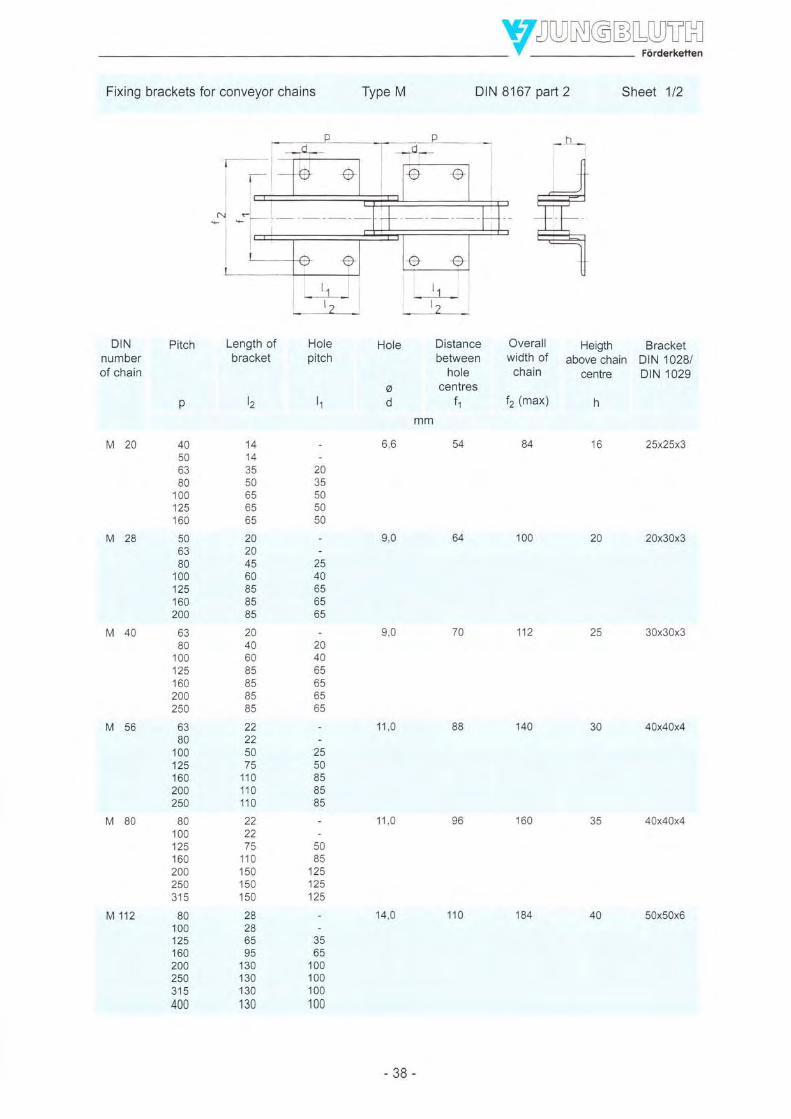
IFixing brackets for conveyor chains Type M DIN 8167 part 2 Sheet 1/2
Overall Heigth Bracketwidth of above chain DIN 1028/chain centre DIN 1029
f2 (max) h
16 25x25x3
20 20x30x3
ZJ 30x30x3
140 JU 40x40x4
40x40x4
DINnumberof chain
M20
M28
M40
M56
Length ofbracket
l2
14143550o36565
20204560B58585
2040608585B5
85
222250
110110110
222275
110150150150
282865
130130130
130
Hole Holepitch
Pitch Distancebetween
holecentres
l1
t^
p
40506380
100125160
506380
100125160200
6380
100125160200250
bJ80
100125160200254
80100125160200250315
80100125160200250315400
84
ad
6,6
2035505050
2540oc6565
204065656565
^508585öc
100649,0
11270on
88
160vo
50öc
125125125
JC65
100100100't00
11 ,0
11 ,0
14,0M 112
-38-
110 184 40 50x50xG
YJUrygqL,HJ."H
t'th
l*
t--/t\rq/ /hrq/
T
r|.\v /haq/hY'
I
I
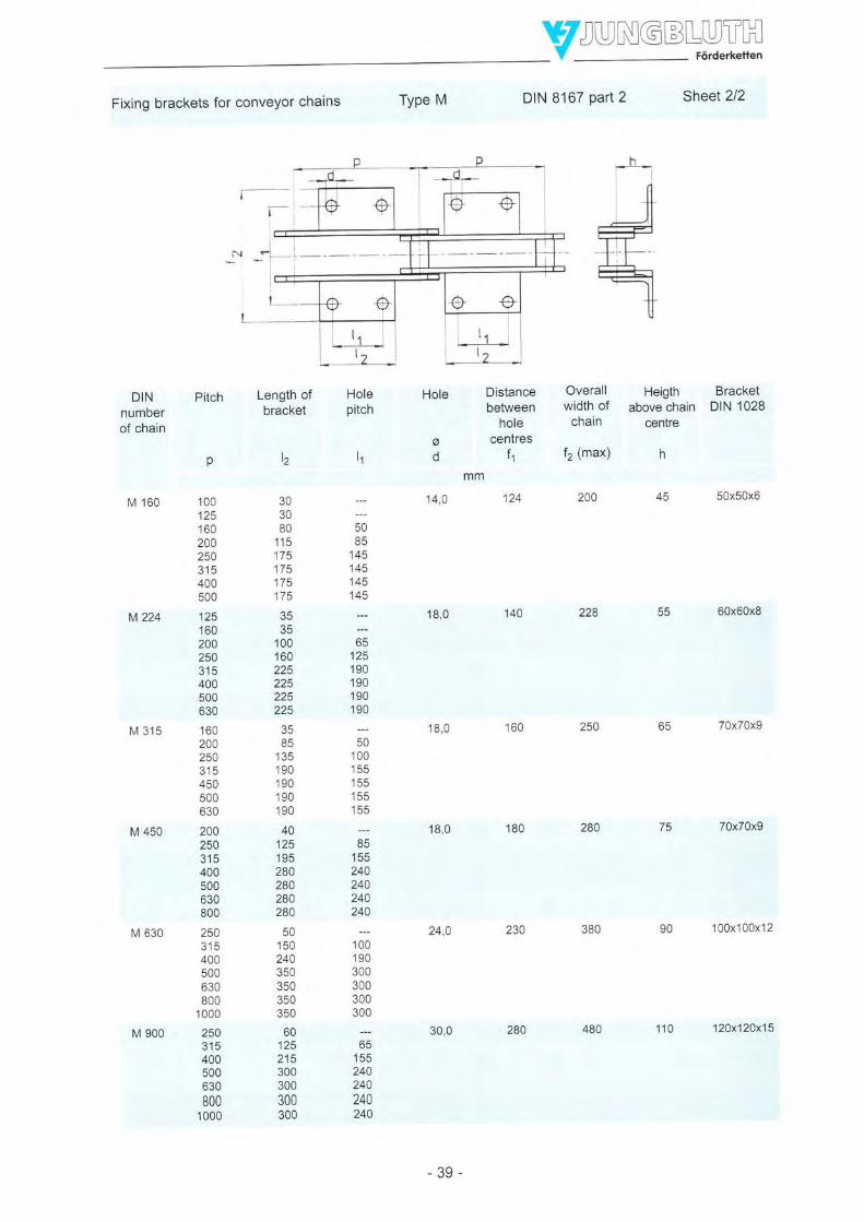
Fixing brackets for conveyor chains Type M DIN 8167 paftz Sheet 2/2
h
ILtnL)l
-
l:t-ffi
+t t-tl|_
----ll-fF
U
ry
DINnumberof chain
Pitch Length ofbracket
I2
303080
44F
175175175175
3535
100160225225225225
35
135190190190190
4012519528028028028A
'150
240350350350350
60125215300300300300
t:
^:bc15524Q24474024Q
Hole
gA
14,0
18,0
18,0
18,0
24.0
Distancebetween
holecentres
f1
124
Overall Heigth Bracketwidth of above chain DIN 1028chain centre
f2 (max) h
M 160
M224
M 315
M 450
M 630
o
100125160200250315400500
125160200254315400500630
160200250315450500630
20025431s400500630800
250J tc400500630800
1 000
250315400500630
8001000
45200 50x50x6
55 60x60x8
65 70x70x9
70x70x9
90 1 00x1 00x1 2
MA
160
180
;;85
1451451454^R
65125190J90190190
;;100155155155155
öc155AO240240244
1;;190300300300300
228
284
380
30,0
230
-39-
280 110 12Ox120x15

YTJUNGBLUTH- V
-
Förderkeften
Conveyor chains with solid PinsDouble-strand chains
Type M DIN 8167 part 1 Sheet 1i2
1000 1250
--
1 010952
1011 1261944 1194
1014 1264937 1187
1015 1265923,8 1173,8
1016 1266908,4 1158,4
1022 1272896 1146
1Q27 1277881 1131
without rollers
with small rollers form A according to DIN 8169
DINnumberof chain
M20
M28
M40
M56
M80
M 112
M 160
M 224
M 315
M 450
M 630
M 900
250
256228,6
257225,4
257221 4
259t17 2
260210,2
260202
zol194
264187
265173,8
315
321293,6
322290,4
322286,4
JZ+282,2
325275,2
325267
326259
329252
330238,8
331223,4
337211
630
637601,4
639597,2
640590,2
640582
641574
644567
645
040538,4
652526
057511
810760,2
810752
B'11
744
814737
815723,8
816708,4
822696
R27
681
Qn
MELW
MELW
MELW
MELW
MELW
MELW
MELW
MELW
MELW
MELW
ME
MELW
Track widthmm
400 500
406 506378,6 478,6
407 507375,4 475,4
407 507371,4 471,4
409 509367,2 467,2
410 510360,2 460,2
410 510352 452
411 511344 444
414 514337 437
415 515323,8 423,8
416 516308,4 408,4
422 522296 396
427 527281 381
-40-
800

vffiHConveyor chains with solid pins
Double-strand chainsType M DIN 8167 part 1 Sheet2l2
with rollers form B and C according to DIN 8169
with flanged rollers form D and E according to DIN 8169
DINnumberof chain
M20
M28
M40
M56
M80
M 112
M 160
M 224
M 315
M 450
M 630
M 900
1800
:
:
:
18141737
18151723,8
18161708,4
1822I oYo
18271681
2000
:
-
:
20141937
20151923,8
20161908,4
20221 896
20271881
rmm
3,0
3,5
4,5
Axisa
d7mm
7,0
8,5
1n n
12,0
15,0
18,0
21,0
25,0
30,0
35,0
42,0
50,0
10,0
12,0
15,0
18,0
21,0
25,0
30,0
36,0
44,0
Sp
MELW
MELW
MELW
MELW
MELW
MELW
MELW
MELW
MELW
MELW
MELW
MELW
mm
1,0
1,5
2,0
z,o
3,0
3,0
3,0
3,5
aq
3,5
8,0
11 ,0
'13,5
Track widthmm
1400 1600
-:
--
:-
14't4 16141337 1537
1415 16151323,8 1523,8
1416 16161308,4 1508,4
1422 16221296 1496
1427 16271281 1481
Axisa
O1
mm
6,0
7,01,0
1,0
5,0
c,c
7,0
-41
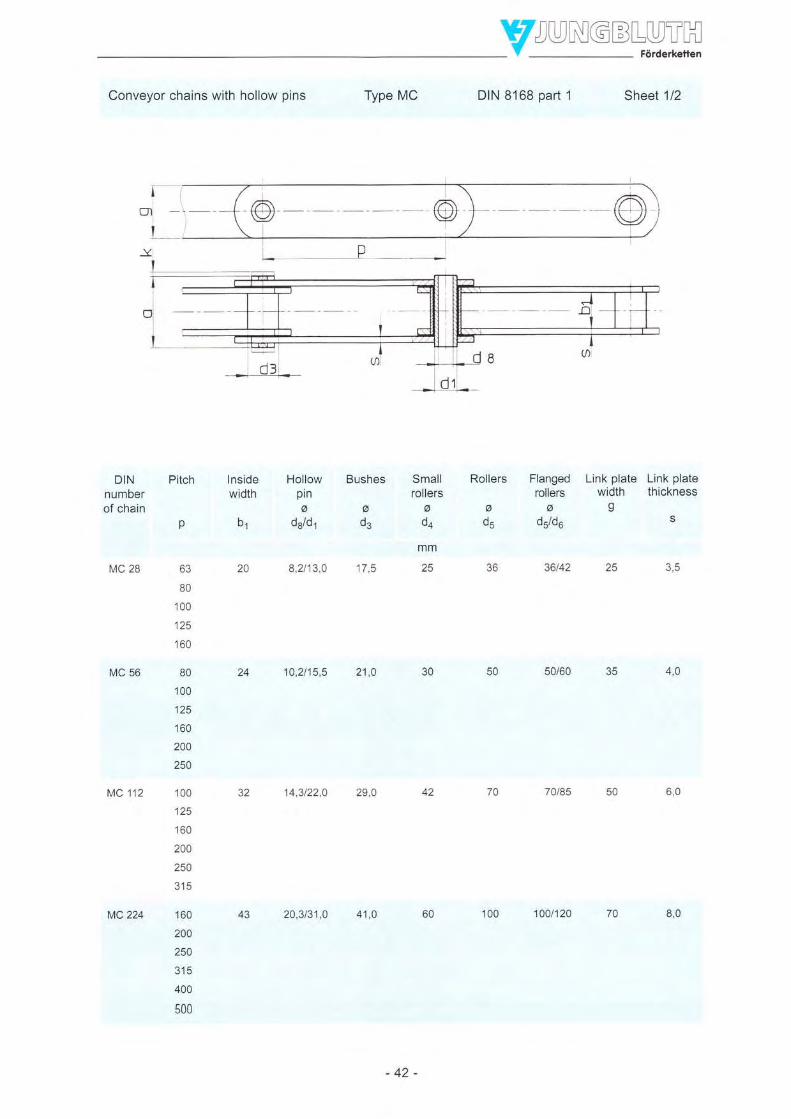
IConveyor chains with hollow pins Type MC DIN 8168 part 1 Sheet 1/2
DINnumberof chain
Insidewidth
b1
20
Smalfrollers
ada
mm
25
Pitch Hollow Bushespinaa
d8/d1 d3
8,2t13,0 17,5
Rollers Flanged Link plate Link plate
, .'Fo width thickness
d5 d5/d6 s
36 36142 25 3,5MC 28
MC 56
MC 112
p
63
BO
100
125
160
80
100
125
160
200
250
100
125
160
200
250
315
160
zta250
315
400
508
4.45024 10.2t15,5 21,0 30
32 14,3t22,0 29,0
50/60 J3
6,042
MC224 43 20,3/31,0 41,O
-42-
60 100 1001120 70 8,0

YTJUNGBLUTHV Fordert(efien
Conveyor chains with hollow Pins Type MC DtN 8168 part 1 Sheet 2/2
Wdght of chainDIN Max.number rivet pin
of chain tength
a
MC 28 39,0
Max. Breakingprojection loadof ctosing
ptnk
mm kN
3,5 28
Articuta- Admis-tion sible arti-
surface culationsunace
pressure
sm' Nlcm'
3,64 1090
withoutroller
2,27
2,08
1,94
1,83
1,73
3,67
3,37
3,14
2,93
2,79
2,67
700
7,33
o,/o
6,02
14,16
13,09
12,23
11,52
10,94
10,51
withsmallroller
kg/m
2,86
2,55
2,31
z, lz
1,96
4,45
4,00
3,64
3,32
3,10
2,g2
9,70
8,70
7,83
7,20
6,71
6,29
17,20
15,52
14,18
13,06
12,16
11,48
withflangedroller
4,29
3,67
3,21
2,84
2,52
7,66
6,57
5,69
4,93
4,38
385
16,46
14,11
12,05
10,59
9,41
8,44
28.g1
24,88
21,67
19,01
16,84
1523
withlargeroller
MC 56 45,0 4,A
MC 112 62.5
5,11 1560
112 oon 1610
co
4,05
3,48
2,72
2,43
7,18
6,19
5,39
4,69
4,19
3,79
15,40
13,26,14 ?.o
10,05
AOq
8,10
27,17
23,4g
20,55
'18,13
16,14
1a,si
4,8
Tf
MC 224 82,0 5,5 224 18,60
-43-
1720

IFixing brackets for conveyor chains Type MC DIN 8168 parr2 Sheet 1/1
DINnumberof chain
Length ofbracket
l2
20
40
60
85
25
25
75
110
150
150
?n
30
80
115
4'7 q
175
Hole
11,O
14,0
18,0
Distancebetween
holecentres
f1
70
Pitch
p
63
80
100
125
160
80
100
125
160
200
250
100
125
160
200
250
315
160
200
250
315
400
500
Holepiteh
It
20
40
65
:.
50
85
125
125
mm
Overall Height Bracketwidth of above chain DIN 1028chain centre
f2 (max) h
MC 28
MC 56
MC 112
1129,0 25 30x30x3
4Ox4Ox4
50x50x6
152
45192
50
85
145
145
35
85
135
190
190
1S0
140
50
100
155
155
155
p
s7
I
/h\P+ l^Yr1
t?Lr
MC 224
-44-
220 65 60x60x8

YTJUNGBLUTHY Forderxeren
Rollers for conveyor chains DIN 8167/8168 DtN 8169
Flanged rollersShape D
Sheet 1/1
Small rollersShape A
Large rollersShape B Shape C Shape E
vzzzzA- || | r.i -tl-f--TclclV777ir Ii-1-IUtr +_l
DINnumberof chain
M2015
M2817
M 40 19
M5623
M8027
M 112 31
M 160 36
M 224 42
M 315 47
M 450 55
M 630 65
M 900 76
MC 28 19
MC 56 23
MC 112 31
M6 224 4?
d6 de
max.b4 bs b7 bs be bro brr
J131 d4
Diameter
d5
Weight
Roller Flangedroller
kg
0,048 0,053
0,081 0,089
0,129 0.142
a,213 0,234
0,354 0,392
0,579 0,632
0,919 1 ,032
1,593 1.753,
2,443 2,745
4,Aü 4,471,
6,548 7,389
11,233 12J5*
0,112 0,124
s,zu 01315
0,746 0,837
?,091 2,3.i9
14 0,5 11 ,0 3,0
16 0,5 ',t2,5 3,5
18 0,5 13,5 4,5
22 0,5 fi,a 5,0
26 0,5 20,0 6,0
29 1,0 22,ß 7,0
34 1,0 25,5 8,5
40 1,0 30,0 10,0
45 1,0 33,0 12,0
sl 2.0 37,A ß,0
61 2,0 45,0 16,0
70 3,0 52,0 1S,0
18 0,5 13,5 4,5
22 0,5 17,0 5,0
29 1,0 22,0 7,0
40 1,0 30,0 :10,0
mm:2,5 4,0 9,0
3,0 4,5 1o,O
3,5 4,5 12,5
4,O 6,0 15,0
5,0 7 ,0 18,0
6,0 7,5 21,0
7,0 8,5 25,0
8,0 1o,o 30,0
10,0 10,5 36,0
12,0 11.5 42,O
13,5 14,5 50,0
15,0 17,0 60,0
3,5 4,5 17,5
4,0 6,0 21 ,O
6,0 7,5 29,0
8,0 10,0 4.1,fi
12,5 25 30
15,0 30 36
18,0 36 42
?1,0 42 50
25,0 50 60
30,0 60 7B
36,0 70 85
42,A 85 100
50,0 100 120
60,0 120 140
70,0 140 170
s5,0 170 210
25,0 36 42
30,0 50 60
42,0 70 85
s0,0 100 1zQ
30
34
40
46
54
65
/3
38
cz
-45-

Y6.4 Carrying Chains with raised Link Plates, DIN 8167
Conveyor chains with solid pins
Carrying chains with raised link platesType MT DIN 8167 part3 Sheet 1/4
DINnumberof chain
Pitch
p
40506380
100
tzc160
50OJ
80100
125160
2AA
80100
125
160
200250
OJ
80
100125160
20025Q
BO
100
125
160
200250
Insidewidth
bl
16
Rollers
ad5
25
;'
";"'Overall Height Thicknesswidth of above chain of link platelinkplate
Tr- s
MT 28
MT 40
MT 56
2,516,025on6,0
3,0303010,07,0
36I z.c8,520
4,0454224
18,0
2A,O
22,5
30,010,0 15,0
rD-Y
28 12.0
-46-
50 50 32,5

Y#UrygqL,Y."T-.H
Conveyor chains with solid PinsCarrying chains with raised link plates
Type MT DIN 8167 part 3 Sheet 2/4
-O"r
NILrr II
DINnumberof chain
Max.rivet pinlength
a
35
Max.projection ofclosing pin
k
7,0
Breakingload
Articulationsurface
AdmissibleartIculation
surfacepressure
N/cnF
2160
Weight
KN
20
cm2
1,32
kg/m
3,01
2,61
2,27
2,00
1,79
1,63
1,49
4,023,48
3,M2,71
2,452,232,08
5,294,584,05
3,623,25
2,992,77
8397,21
6,33
5,635.Q2
4,58
4,23
11 ,179,72
6,826,24
5,76
MT 20
MT 28
MT 40
MT 56
1,758,040
2,3840on45
5610,052
2440
2294
2400
243A3,30
_ /D_\yI
MT 80 62 12,0 BO
-47 -
4,68

vzyrygq+.v"TH
Conveyor chains with solid pinsCarrying chains with raised link plates
Type MT DIN 8167 part 3 Sheet 314
DfNnumberof chain
Pitch
p
BO
100tzJ160200250315
100tzc160200250315
125160200250315400
160200250315400
200250315400500
254315400500
250315
400500
lnsidewidlh
b1
32
Pins
frdl
15,0
Bushes
ad3
21.0
Rollers
ads
60
Overall Height Thicknesswidth of above chain of link platelink plate centre
9rgzs
MT 112
MT 160
MI 224
MT 3T5
MT 450
MT 630
6,040,060
37
43
18,0
21 ,0
25,0
36,ü
30,0
42,0
60,0
25,0 7,045,0
8,060,0
70
90
70
B5
10010036,0
12012030,0
65,0 10,0
80,0 12,0
90,0 14,014014050,066
MT 9OO 7B 44,0
-48-
170 180 120,0 16,0

Type MT DIN 8167 part 3 Sheet 4/4Conveyor chains with solid PinsCarrying chains with raised link plates
DINnumberof chain
Max.rivet pinlength
a
73
Max.projection ofclosing pin
k
14.0
Breakingload
Articulationsurface
cmt
6,75
Admissiblearticulation
surfacepressure
N/crn'
2370
Weight
Mr 12
16,0
18,0
21,O
zc,v
30,0
224
630
12,60
17,50
24,60
34,56
2440
2570
zozv
zil4
kglm
17,5115,1413,2411 ,5810,399,458,66
23,0319,9617,2815,3613,8312,56
32,3127,7224,4421 ,8119,6417,87
41 ,5236,3632,2328,8226,03
56,9250,0644,3910 7A
36,33
75-8866,5858,9753,33
123,44107,3094,10
84,33
KN
112
MT 160 85
Mr 224
MT 315
MT 450
MT 630 154
9,36160
98
alE112
450135
900
A-Y
MT 9OO 180 37,0
-49-
49,28 2610

I6.5 Trouqh Convevor Chains, DIN 816518167
Trough conveyor chains with solid pins Type TF similar to DIN 8165 part 1 Sheet 1/1
DINnumoerof chain
TF 40
TF 63
TF 90
TF 112
TF 140
TF 180
TF 250
TF 315
TF 4OO
TF 5OO
lnsidewidth
b1
'18
22
45
p
4063
100OJ
10012516063
100tzJ160200zcu100lzc160200250100125160200250315125160204250?1A4001251602002503154001602002503154001602002503'15400160200250315400500200250315400500
Bushes
g
d3
mm
Pins
ao1
10
12
Width Thick- Breaking Articula- Admis- Weightof link ness of load tion sible arti- withoutplate link plate surface culation scraper
surfaceg s pressure
kN cm2 N/cm' kg/m
26 3 40 2,5 2680 2,702,161,82
30 4 63 3,7 2840 8,8?2,712,53
35 5 90 5,0 3000 5,284,344,03
i,ää40 6 112 6,8 2750 6,17
AAO
i"6+4,73
45 6 140 8,6 2720 7,616,94
5,92
?t?50 I 180 12,3 2440 10,78
9,809,09
ä:ö77,69
60 B 250 18,7 2230 14,7813,1 I12.0611,1610,41I,B0
70 10 315 25,8 2040 20,3818,5017,0015.7614,75
70 12 400 30,7 2170 24,2722,0520,2818,8117,62
B0 12 500 38,2 2180 30,4027,3424,88
61"r319,98
100 12 630 48,7 2160 36,9633,3430,3427,9026,09
15
18
2014
1a
20
26
32
TF 630
36
-50-

vTrough conveyor chains with solid pins Type TF similar to DIN 8'165 part 1 Examples
p -_
p_l A
-51 -

IWHTrough conveyor chains with solid pins Type TFM similar to DIN 8167 part 1 Sheet 1/2
Type A
r'j
DIN pitchnumberof chain
v
40506380
100125160
506380
100125160200
6380
100125160200250
80100125160200250
80100125160200250315
80100125160200250315400
Insidewidth
b1
16
Pins
2,518on6,0
Bushes Width of Thick-link plate ness of
link plateao3gs
mm
Breaking Articula-load tion
sudace
kN cm'
20 1,32
Admis- Weightsible arti- withoutculation scrapersurface
pressure
N/cm, kg/m
2160 1,281,161,070,990,930,890,85
2290 1,571,441,341,26
1,141,10
2400 2,232,051,911,811 ,711,641qo
2430 3,323,012,792,612,452,332,24
2440 4,644,26
3,50
3,23
2370 6,736,135,665,254,954,714,524,36
Au1
TFM 20
TFM 28
TFM 40
TFM 56
TFM 80
18
20
7.0 10,0 20 3,0 28 1,75
I z,c zc J,c 40 2,38
zq 10,0 15,0 30 4.0 56
28 12,0 18,0 35 5,0 80 4,68
15,0 21 ,0 40 6,0
Type C
rype b Type D
rFM Y2
-52-
112 6,75

tWHTrough conveyor chains with solid pins Type TFM similar to DIN 8167 part 1 Sheet 212
Type E Type F
DIN pitchnumberof chain
p
TFM 160 100125160200250315400500
TFM224 125160200250315400500630
TFM 315 160200250315400500630
TFM 450 2002503'15400500630800
TFM 630 250315400500630800
1 000
TFM 900 250?1q400500630800
1 000
Pins Bushes Width oflink plate
s
50
Thick-ness of
link plate
S
7,0
Breakingload
KN
160
Insidewidth
D1
37
ad3
aul
4Ä n
120
Admis- Weightsible arti- withoutculation scrapersurface
pressure
N/cm2 kg/m
9,36 2440 9,618,788,067,557,146,806,526,32
12,60 2540 12,9911 ,7910,9410,269,709,248,908,62
17 ,50 2570 18,0516,6415,5114,57'13,8'1
13,2512,78
24,60 2620 24,0522,2520,7719,5618,6617,9217,32
34,56 2610 34,5831,9829,8528,2826,9825,9225,13
49,28 2610 51.0446,7343,2040,5938,4336,6735,37
Arlicula-tlon
surface
em2
1B
8,0603043
31510,0703625Äa
45012,080423056
3666
78 44 60
-53-
16,0 900
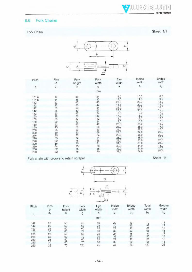
YWH6.6 Fork Chains
Fork Chain
-j-r-T-' o1 -Bridgewidth
b2
..o
Fork Eyewidth width
ga
Forkheight
n
mm
192825302530253045
IJ1518231B20182036
203027322732273247
4262607260706070
120
Pins
O1
mm
24304642
62244242244650606664
5871706570
9,013,020,014. q
25,028,0
9,017,016,0on
23,023.025,029,026,026,028,031,032,032,032.0
1A
.A
22252525201825202225253035353235343232
36364050505047364747
5350607272757575
75
p
10'1 ,6101,6142142142142142'150'150
150160160200200216220220220250260260
Fork chain with groove to retain scraper
Totalwidth
b3
7087819681958,1
95150
Pins Forko heightd, h
25 5025 5025 5030 6025 5030 6025 5030 6035 70
142142160175200200250250t3u
Forkwidth
g
r h,
Eye lnsidewidth width
abr
Bridgewidth
D2
lnsidewidth
b1
10,014,022,020,026,530,010,018,018,010,025,025,027,032,028,028,030,033,034,034,034,0
Sheet 1/1
6,09,0
13,013,016,015,0
7,012,012,07,0
15,013,518,020,020,020,025,021,018,020,020,0
Sheet 1/1
Groovewidth
1212121612
1213al
-54-

WH
Typel(BT)
Examples for types of fork chains available
Type2(T)
ffiJType 9
Type 7
Type 3
nF-\ttI H- lffi@l@l@p: U
Type4(U)
Type5(O)
Type 10
Type 11
w1
Type I
Type6(00)Type 12

vW*H6.7 Bush Chains
Bush chain
lnside Pinswidth
DrN 8164 Sheet 1/1
A Plug-in link with split-pin fastener
z1-'+l€F- €}+\f,----=-=!-/
@
-
-l lJ _ _L; L_"ll'ilrll_qr-TF-=--qr.TF--
B Cranked link with solit-pin fastener
Pitch Bushes
6d3
mm
v
12
15
17
18
20
26
32
Link Link pla-plate te thick-width ness
gs
Rivet Closing Breaking Articula- Split-pin Weightpin pin load tion
length length surface
ä1 max. a2 max. *) DIN 94
kN cmz
27 33 12,5 1,1 1,6x12
?d1
6
b1
1,8
2,5
3,1
4.7
5,0
39
44
50
55
62
80
34
37
44
46
6B
14
19
24
28
30
26
44
10
tz
14
18
zz
2A
22
ZJ
50
15
20
25
4A
50
60
25,4
40,0
50,0
63,0
100,0
160,0
R6
14,6
2,4{4
2,5x16
3,2Y20
3,2x20
4,0x22
5,0x32
5.0x32
kglm
1,2
2,1
2,6
4,A
4,3
6,0
9,0
15,0
*) lf there are cranked links (to be avoided, if possible), calculate with breaking load factor 0.8 only!
-56-

Examples for types of pin joints available
round riveted
{-@- -rh-\=tr/
riveted and countersunk with cotter pin
with adjusting ring, adapter sleeveand locking pin
with axle holder
settled
with retaining ringor circlip
externally running rollers with washer and cotter pin
with nut or castle nut and cotter pin,grease nipple, grease drilling
ryI\ts
.\ [\ til tll
ZN NW
-57 -

v/ruNsqqy.T.H
7 lllustrations of chain tYPes
Plate band chain for the automobile ndustry p=66
Asphalt chain, scraper chain p=150 Bush conveyor chain p=200
Conveyor chain with angle bracket p=80
Bush conveyo" chain w tn ock nut o=250 Conveyor chain for pipe conveyor p=63
Conveyor chain for round steel conveyor p=80
Corveyo' cnatr for nire covering p=63
Special chain, measuring table steel industry p=200
-58-
Special chain for plasterboard manufaciure p=80

YW.H
Doub e-strand hook ehain / stee inCustrv o=250
Double-st'ard cia' p:250
R qh e nn a'ör rn2 n fnr q, .a nhtorhn qp n=100
Charr ,t "ee '0" 'o"ned gv g 1 7=$ p='a)
S ^gle-st'ar^d ioo( cha' steel roust'y p=250
-" nlo n'ate 66p rcr 6r p=)lf
B plara'clarr s a,grte'lo,se p=7$ I
Cha n whee z=10, p=100
Ä-fr - ^r: n \Loo t=)\'7=ll{ J
59-
P n on shaft z=7 . a=21C

YZUryGqL"Y_T_"H
Göttingen
Bad HersfeldI
Fulda
Würzburg
Coming from the North / West (A7):
Take the exit Kirchheim, turn right, then right again onto the B 454 heading towards Niederaula. Afterabout 4 km turn left onto the B 62. Follow this road for about 6 km until you come to Bad Hersfeld-Asbach where you will find Alsfelder Strasse 73.
Coming from the South (A7):
Take the exit Niederaula, turn left onto the B 62 towards Niederaula. Follow this road for about B kmuntil you reach Bad Hersfeld-Asbach where you will find Alsfelder strasse 73.
Coming from the East (A4):
Take the exit Bad Hersfeld and go about 2 km towards Bad Hersfeld (B 27). Turn left onto the B 62signposted Alsfeld. Follow this road for about 1 km after reaching Bad Hersfeld-Asbach you will cometo Alsfelder Strasse 73.
How to contact us
Please feel free to call us at any time. Alternatively, you can reach us by mail or fax:
I How to find us
Schwalmstadt
i^r*r
Kirchheimer Dr
^
^t
t
Eisenach
Hattenbacher Dr IBad Salzungen
Mail address:
i nfo@j u n g bl uth-ketten.de
i^t
lt
Telephone number:
+49-6621-9294-0
Fax number:
+49-6621-9294-10
Hannover
-ou-

Karl Jungbluth Kettenfabrik GmbH & Co. KGAlsfelder Strasse 73D-36251Bad Hersfeld
ZTÜY\\GEffiZDIN EN ISO 9OO1
Reg.+.h 73 100 1064
Te lephon + 49 -6621 -929 4-0Telefax +49-6621-9294-10www.jungbluth-ketten.dei nfo@u n gbluth-ketten.de