special seismic problems
DESCRIPTION
seismicTRANSCRIPT

SPECIAL SEISMIC PROBLEMS OF HIGH
ENERGY PIPING
L. PEČÍNKA
IAGE Workshop, 2011
30.11.2011 1

DEFINITION AND TASK
High energy fluid systems: Fluid systems that, during normal
plant conditions are either in operation or maintained pressurized
under conditions
either or both of the following are met
maximum operation temperature exceeds 100°C (200°F) or
maximum operating pressure exceeds 2MPa (275 psig.)
Tasks
development of ASME Code Section III
break postulation: history and rules
ageing management: Dynamic Behavious of Piping Systems with
Local Degradation
redefinition of L LOCA: influence of SSE
30.11.2011 2

DEVELOPMENT OF ASME CODE Section III :
HISTORICAL MILESTONES
1915 : STANDARD SPECIFICATION FOR POWER PIPING
1935 : AMERICAN TENTATIVE STANDARD FOR PRESSURE PIPING
1942 : ASA B 31.1 AMERICAN STANDARD CODE FOR PRESSURE PIPING
1953 : REVISION OF THE 1942 CODE ASA B 31.1a – 1953
TYPICAL FEATURE: ALLOWABLE STRESSES IDENTICAL
WITH BOILER CODE
1955 : REVISION OF THE 1953 CODE: B31.1 – 1955
PRESSURE DESIGN
Minimum thiskness of pipe wall
Allowable working pressure of pipe
Only in words: sustained external loadings
Formulated eq. (10) for thermal expansions including „i“
milestone!
30.11.2011 3
hS

DEVELOPMENT OF ASME CODE SECTION III :
HISTORICAL MILESTONES cont. 1
1963 issued Section III „Nuclear Pressure Vessels“
Design-by-analysis approach published
B 31.1 – 1953 not included
1969 issued USAS B31.7 „Nuclear Power Plant Piping Class 1, 2
and 3“
Simplified Design-by-analysis approach used for Class 1
Class 2/3 nearly identical with B 31.7
1971 issued ASME Code Section III. B 31.7 included
Article NB 3600 Piping Design for Class 1
Article NB 3600 Piping Design for Class 2/3
Seismic event not included for Class 2
30.11.2011 4
mBBaaab STTECTE 312
131
10
iMI
DoC
t
PDoC
2221

DEVELOPMENT OF ASME CODE SECTION III :
HISTORICAL MILESTONES cont. 2
1972 issued Winter Addenda of Section III.
Seismic event included
For Class 2/3 Piping following equations formulaten
For sustained loads
For occasional loads
30.11.2011 5
8
hba
n
SW
MMi
t
PDo2.175.0
25.0
9
hba
n
SW
MMi
t
PDo
75.02
5.0

DEVELOPMENT OF ASME CODE SECTION III :
HISTORICAL MILESTONES cont. 3
Introduced eq (11) as a sum of eqs (8) and (10) in form
Introduced „Servis Limits“
normal, upset, emergency, faulted
1974 : Service Limits in 1972 Winter Addenda changed to Service
Limits A, B, C, D
1981 : introduced PRIMARY STRESS INDICES B1 and B2
INCREASED ALLOWABLE STRESSES FOR SERVICE LIMITS A and B
30.11.2011 6
Ahca
n
SSW
Mi
W
Mi
t
PD
75.075.02
5.0 0
AhA SSfS 25.025.1
hA
n
SW
MB
t
DPB 5.1
22
max1
8

DEVELOPMENT OF ASME CODE SECTION III :
HISTORICAL MILESTONES cont. 4
Eq. (9) : allowable stresses for Level C and D increased to
Level C:
Level D:
effect of non repeated single anchor movement
for Class 1 Eq. (10) has been changed to
30.11.2011 7
yhBA
n
SorSW
MMB
t
DPB 5.18.1
22
max1
Ac S
W
Mi
yh SorS 8.125.2
yh SorS 0.205.3
CD S
W
Mi 3
mBBaaabi STTECM
I
DC
t
DPC 3
22321
9
10

DEVELOPMENT OF ASME CODE SECTION III :
HISTORICAL MILESTONES cont. 5
GENERAL COMMENTS
In revision of ASME CODE Section III. Articles NB 3600 and NC 3600
after 1981 the allowable stresses have been increased
At present US NCR accepted only Revision 1992
It is evident that develpment of Class 2 Code was ahead of Class 1
After 1981 NB 3600 and NC 3600 both Articles are partly unified –
introduction of B1 and B2 indices in Eq. (8) and (9) of NC 3653
30.11.2011 8

BREAK POSTULATION: HISTORY AND RULES
HISTORICAL DATA
1959 : US NPP SHIPPINGPORT DESIGN: MAXIMUM CREDIBLE
ACCIDENT
1975 : US NRC STANDARD REVIEW PLAN 3.6.2 MEB 3-1: PIPE
BREAK OUTSIDE CONTAINMENT
RG 1.46 for piping inside containment
Definition of high energy piping
1981 : EXTENSION OF MEB 3-1 TO INSIDE AND OUTSIDE PIPINGS
1987 : MEB 3-1 WENT THROUGH SOME SUBSTANTIAL CHANGES
1986 : SRP 3.6.3 LBB
2005: APPARITION PRBABILISTIC LBB
REDEFINITION OF L LOCA
30.11.2011 9

BREAK POSTULATION: HISTORY AND RULES
HISTORICAL DATA cont. 1
1975 : SRP 3.6.2, MEB 3-1
FOR ASME CODE Section III. Class 1 Piping
in containment penetration area: breaks need not be postulated if
-
- The cumulative usage factor (CUF) should be less than 0.1
in aress other than containment penetration: breaks should be
postulated
- At therminal ends
- At intermediate locations where
- At intermediate locations where CUF exced 0.1
30.11.2011 10
m
m
bbaaab
i
S
STTEC
W
MC
t
DPC
3
4.28.02
231
10
m
m
bbaaabi
S
STTEC
W
MC
t
DPC
3
4.28.0
2321

BREAK POSTULATION: HISTORY AND RULES cont. 2
If two intermediate location cannot be determinated, two highest
stress location should be selected. If the piping run has only one
change or no change of direction, only one intermediate location
should be postulated
FOR ASME Code Section III., Class 2 Piping
in contaiment penetration area: breaks need not be postulated if
in areas other than containment penetration: breaks should be
postulated
At terminal ends
30.11.2011 11
Ah
iBAi SS
W
Mi
W
MM
t
DP
2.18.075.0
25.0

BREAK POSTULATION: HISTORY AND RULES cont. 3
At two locations with at least 10% diference in stress, or if stresses
differ by less than 10%, two location separated by a change of
direction of the pipe run
At each location where breaks shall be postulated, pipe whip
restrainst shall be postulated and calculated
1986: US NRC issued Generic Letter 87-11: Relaxation in Arbitrary
Intermediate Pipe Rupture Requirements
Arbitrary intermediate pipe reptures as specified in 1975 SRP edition
for Class 1 and Class 2/3 piping are now no longer mentioned or
defined in MEB 3-1
30.11.2011 12
Ah
cBAi SS
W
Mi
W
MM
t
DP
2.18.075.0
25.0
109

BREAK POSTULATION: HISTORY AND RULES cont. 4
For Class 2 piping Eqs. (8) and (9) of ASME Code Section III
Article NC 3600 the stress indices B1 and B2 where introduced
and stress limits to 1.5. (Eq.(8)) and 1.8 (Eq.(9))
PIPE WHIP RESTRAINTS
Design features are based on
Displacement and bending or
Displacement and rotation
30.11.2011 13
Typical transverse restaint based on displacement: coper bumpers and celluar concretering
hShS

BREAK POSTULATION: HISTORY AND RULES cont. 5
30.11.2011 14
Stainless steel rods: fixed
U shape rods aroung sleeve
Stainless steel rods: fixed
U shape rods without sleeve
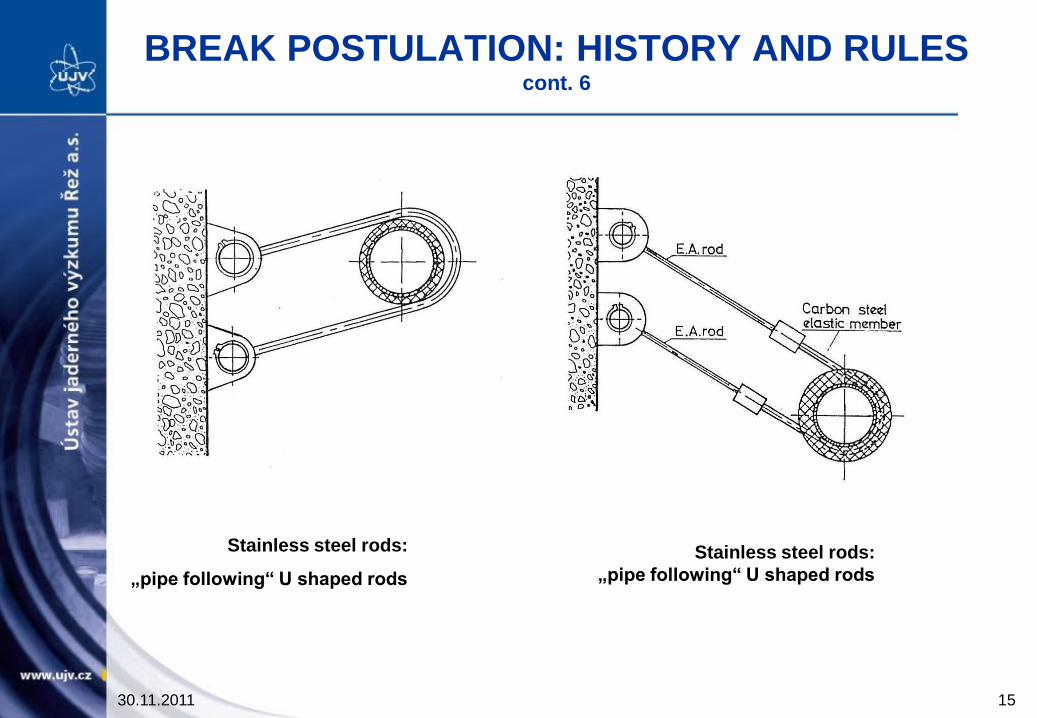
BREAK POSTULATION: HISTORY AND RULES cont. 6
30.11.2011 15
Stainless steel rods:
„pipe following“ U shaped rods
Stainless steel rods:
„pipe following“ U shaped rods

BREAK POSTULATION: HISTORY AND RULES cont. 7
30.11.2011 16
Attachment of stainless steel bar
to steel frame
Attachment of stainless steel bar
for hinge mechanism

BREAK POSTULATION: HISTORY AND RULES cont. 8
Attachment of stainless steel bar
to concrete embedment

30.11.2011 18
An Experimental Study on Dynamic Behavior of
Piping Systems with Local Degradation
National Research Institute for Earth Science and Disaster Prevention
30.11.2011 18
Purpose
Degradation of piping systems caused by Aging Effects
(Wall thinning / Cracks)
How does the piping systems
with local degradation
behave under the destructive earthquake?
An experimental research program is being conducted.
(1996 – 2000)
30.11.2011 19

Pipe Element Tests
Cyclic 4-point bending tests using straight pipes with degradation
Purpose : To clarify the failure mode of degraded pipes under
the high level bending loading
Piping System Tests
Shaking table tests using piping systém models with degradation
Purpose : To clarify the effect of degradation on piping
system´s dynamic behavior and failure mode
30.11.2011 20

Pipe Element Tests
Specimens with Wall Thinning
Degradation : Full circumferential thinned wall (Made by machining)
Material : Carbn Steel STS410
Internal Pressure : 11MPa / 0MPa
The Figure of the Thinned Wall Specimens
t = 4.3mm for 50% wall thinning, 2.15mm for 75% wall thinning
30.11.2011 21

Failure mode of thinned wall pipes
#01 Low cycle fatigue with
ratcher deformation
Pressurized specimens with
50% of wall thinning
Hoop stress by internal pressure
at thinned wall part :
Circumferential cracks were
caused by cyclic bending load.
y45.0
Before the bending test
Swelling by ratchet Crack
After the bending test
30.11.2011 22

30.11.2011 23
Failure mode of thinned wall pipes
#02 Buckling and Low – cycle fatigue
The 50% of thinned wall specimen
without internal pressure and water
Local buckling occurred at the thinned
wall part during cyclic loading.
Cracks caused at the bottom of
buckling deformation.
A full circumferential break was caused
by the following a few cycles.
(View from loading direction)
(View from the upper side)
30.11.2011 23

30.11.2011 24
Failure mode of thinned wall pipes
#03 Combined mode with ratchet,
low – cycle fatigue and burst
Pressurized specimens with
75% of wall thinning
Hoop stress by internal pressure
at thinned wall part:
The wall thickness decreased from 2.15 mm
to 1.1 – 1.6 mm because of ratcheting.
Cracks penetrated in the circumferential direction,
and in the axial direction as well.
y9.0Circumferential cracks
Axial cracks
30.11.2011 24

3D_A01
30.11.2011 25
Piping System Tests
Material: Carbon Steel STPT370
Defect type: No degradation Internal Pressure: 10 MPa
Material: Carbon Steel FSGP Elbow & Carbon Steel STPT370
Defect type: Wall thinning at Elbow Internal Pressure: 10 MPa
Material: Stainless Steel SUS304 & Carbon Steel STP370
Defect type: Partial EDM notch Internal Pressure: 8 MPa
3D_C01
3D_D01
30.11.2011 25

30.11.2011 26
3-D Piping model for piping system tests
Wall thickness of Elbow1 and Elbow2 were thinned for 3D_C01
A narrow band random wave was used for the excitation tests
30.11.2011 26

30.11.2011 27
Test Results of 3-D Piping System Tests
3D_A01: 2.78Hz 3D_C01: 2.42Hz 3D_D01: 2.79Hz
(Without defects) (Wall thinning at Elbow) (Partial EDM notch
at straight pipe)
Relation between Input Acceleration
and Response Acceleration at Elbow 3
Relation between Input Acceleration
and Range of Elbow Deformation Angle
30.11.2011 27

30.11.2011 28
Test Results of 3-D Piping System Tests
Failure mode
3D_A01: 20 times excitation
in elastic – plastic level
3D_C01: 6 times excitation
in elastic – plastic level
Fatigue cracks in the longitudinal direction at
the side surgace of Elbow1
30.11.2011 28

30.11.2011 29
Conclusion
The failure mode of thinned wall pipe changes according to the
condition of wall thinning and internal pressure.
Wall thinning at elbows in a piping system affects its natural
frequency, reduces the strength, and increases the deformation
of the piping system. A small crack has little or no influence
on the piping system´s vibration characteristic.
The failure mode of 3-D piping models with and without
wall thinning was low-cycle fatigue failure at an elbow.
30.11.2011 29

30.11.2011 30
REDEFINITION OF LARGE LOCA
US NRC NUREG – 1829, Vol. 1
„Estimating Loss-of-Coolant Accident (LOCA) Frequencies
Through the Elicitation Process“
What is „elicitation“ process?
Results of the elicitation process
30.11.2011 30

BACKGROUND
SOLUTION OF MANY MECHANICAL PROBLEMS (DESIGN,
INTEGRITY) IS COMPLICATED
ADVANTAGES OF ELICITATION APPROACH
ESTABLISHED PROCESS USED US NRC (NUREG/CR-5424, US NRC,
1990)
NO DEVELOP WORK NEEDED
USABLE QUICKLY
USED BEFORE FOR COMPLEX PROBLEMS WITH LITTLE DATA
ABLE TO CONSOLIDATE AND QUANTIFY VARIOUS DATA STREAMS
SERVICE HISTORY
PFM INSIGHTS
EXPERT KNOWLEDGE ON PROBLEMS OF INTEREST
30.11.2011 31

30.11.2011 32
PANEL SELECTION
POTENTIAL PANEL MEMBERS MAY BE SEEKED WITHIN
INDUSTRY
ACADEMIA
NATIONAL LABORATORIES
CONTRACTING AGENCIES
INTERNATIONAL AGENCIES
30.11.2011 32

FLOWCHART OF THE OVERALL ELICITAION
PROCESS
FLOWCHART OF THE OVERALL ELICITAION
PROCESS
30.11.2011 33

30.11.2011 34
ELICITATION TRAINING
CONSTRUCTING THE PANEL WITH EXPERTS FROM ALL RELEVANT TECHNICAL AREAS AND INSTITUTIONAL/ORGANISATIONAL AFFILIATIONS
CONDUCTING ELICITATION TRAINING TO IDENTIFY POSSIBLE SOURCES OF BIAS AND CONDUCT AN EXERCISE INVOLVING „ALMANAC-TYPE“ QUESTIONS WITH KNOWN ANSWERS
PROVIDING OPERATING EXPERIENCE DATA AND BASE CASE SCENARIOS FOR ANCHORING AND VALIDATING RESPONSES TO THE PANEL
FORMULATING THE ELICITATION QUESTIONS TO AVOID RESPONSE BIAS
CONDUCTING INDIVIDUAL ELICITATION QUESTIONS TO ELIMINATE THE POSSIBILITY OF GROUP DYNAMICS INFLUENCING PANELLIST RESPONSES
30.11.2011 34

30.11.2011 35
ELICITATION TRAINING – cont. 1
THE ELICITATION PROCESS HAS THREE SPECIFIC PURPOSES
TO DISCUSS SOURCES OF BIAS IN THE ELICITATION
PROCEDURE
TO FAMILIARISE THE PANELLIST WITH THE TYPE OF
RESPONSES WHICH THEY WILL BE ASKED TO MAKE
TO PROVIDE THE PANELLISTS WITH PRACTICE IN MAKING
ELICITATION RESPONSES USING TRAINING EXERCISE
30.11.2011 35
30.11.2011 36
ELICITATION TRAINING – cont. 2
MOTIVATION BIASES
SOCIAL PRESSURE (LOBBING)
MISINTERPRETATION IF THE ELICITATION QUESTION STRUCTURE
IS INCONSISTENT WITH A PANELLIST’S THOUGHT PROCESS
MISINTERPRETATION DUE TO INCORRECT ASSUMPTIONS ABOUT
THE DATA OR THE MODELS USED TO ANALYZE THE ISSUE
WITHFUL THINKING AS THE RESULT OF INSTITUTIONAL BIAS
30.11.2011 36

ELICITATION TRAINING – cont. 3
COGNITIVE BIASES
INCONSISTENCY DUE TO MULTIPLE ISSUES, ASSUMPTIONS,
DEFINITIONS OR ALGORITHMS INVOLVED
PANELLIST MAKES A RELATIVE COMPARISON TO A BASE CASE
AND DOES NOT SUFFICIENTLY ADJUST HIS RESPONSE WITH
RESPECT TO THE BASE CASE ESTIMATES
PANELLIST’S OPINION IS OVERLY INFLUENCED BY THE RECENT
OCCURENCE OF A DRAMATIC EVENT
UNDERESTIMATING OF UNCERTAINTY
30.11.2011 37

TRAINING EXERCISE
CONDUCTED AS A PART OF FIRST GROUP MEETING
CONSISTED OF ASKING THE PANELLISTS A NUMBER OF
QUANTITATIVE QUESTIONS WITH KNOWN ANSWERS BUT IN A
SUBJECT AREA WITH WHICH THEY ARE RELATIVELY
UNFAMILIAR
THE PURPOSE OF THIS QUESTIONS
TO ACCUSTOM THE PANELLISTS TO THE TYPE OF RESPONSES
THAT WILL BE REQUIRED TO PROVIDE IN THEIR ELICITATIONS
TO DEMONSTRATED TO THE PANELLISTS THAT ALTHOUGH
INDIVIDUALLY MAY BE HIGHLY UNCERTAIN ABOUT THEIR
RESPONDSED, THE GROUP RESPONSE IS CLOSER TO THE
CORRECT ANSWER THAN THE INDIVIDUAL RESPONSES.
30.11.2011 38
INDIVIDUAL ELICITATIONS
EACH PANEL MEMBER HAS CERTAIN TIME (IN MONTHS) TO PREPARE THEIR ELICITATION RESPONSES
DURING THIS TIME PERIOD INDIVIDUAL ELICITATION SESSIONS ARE CONDUCTED SEPARATELY BETWEEN EACH PANEL MEMBER AND THE FACILITATION TEAM
THE OBJECTIVES FOR THE INDIVIDUAL ELICITATION SESSIONS
IDENTIFY ANY INCONSISTENCIES BETWEEN THE QUANTITATIVE AND QUALITATIVE RESPONSE
PROVIDE ADDITIONAL CLARIFICATION TO THE ELICITATION QUESTIONS, IF NECESSARY
IDENTIFY NECESSARY FOLLOW-ON WORK FOR EACH PANEL MEMBER
30.11.2011 39

PRACTICAL APPLICATION – TRANSITION
BREAK SIZE ELICITATION STRUCTURE
PRACTICAL APPLICATION – TRANSITION
BREAK SIZE ELICITATION STRUCTURE
30.11.2011 40

MATERIAL AGEING DEGRADATION
MECHANISMS
30.11.2011 41

REACTOR PRESSURE VESSEL FAILURE
MODES
REACTOR PRESSURE VESSEL FAILURE
MODES
30.11.2011 42

LOADING HISTORY VARIABLES
30.11.2011 43

CONCLUSIONS
EXPERT ELICITATION IS FORMAL PROCESS FOR PROVIDING
QUANTITATIVE ESTIMATES OF THE FREQUENCIES OF
PHYSICAL PHENOMENA WHEN THE REQUIRED DATA IS
SPARSE AND WHEN THE SUBJECT IS TOO COMPLEX TO
ADEQUATE MODEL
THE PROCESS CONSISTED OF A NUMBER OF STEPS
THE PROJECT STAFF IDENTIFIED MANY OF ISSUES TO BE
EVALUATED THROUGH A PILOT ELICITATION
THE PANEL MEMBERS ARE SELECTED FOR THE FORMAL
ELICITATION
30.11.2011 44

CONCLUSIONS – cont. 1
THE PROJECT STAFF GATHERS BACKGROUND MATERIAL AND PREPARES AN INITIAL FORMULATION OF THE TECHNICAL ISSUES
AT THE INITIAL MEETING THE PANEL DISCUSES THE ISSUES AND DEVELOPED A FINAL FORMULATION FOR THE ELICITATION STRUCTURE
AFTER INITIAL MEETING THE STAFF PREPARE A DRAFT ELICITATION QUESTIONNAIRE AND ITERATED WITH THE PANEL TO DEVELOPED FINAL QUESTIONNAIRE
THE PANELLISTS DEVELOP THEIR INITIAL ESTIMATES
A SECOND MEETING IS HELD WITH ENTIRE PANEL TO REVIEW THE ELICITATION QUESTIONS AND TO FINALIZE THE FORMULATION OF REMAINING TECHNICAL ISSUES
AT HOME INSTITUTIONS THE PANEL MEMBERS PERFORMED ANALYSES AND COMPUTATIONS TO DEVELOPED ANSWERS TO THE ELICITATION QUESTIONNAIRE
30.11.2011 45

CONCLUSIONS – cont. 2
IN THE CASE OF PROBABILISTIC QUESTIONS THE INDIVIDUAL
AND GROUP ESTIMATES FOR THE MEANS, MEDIANS, 5TH AND
95TH PERCENTILES OF THE EVENT UNDER EVALUATION
FREQUENCY DISTRIBUTIONS SHALL BE CALCULATED
THE STAFF DEFINE PRINCIPAL ASSUMPTIONS AND CHOICES
THE EXPERT ELICITATION PROCESS US NRC USED TO
EVALUATE REACTOR RISK (NUREG-1150)
DEVELOP SEISMIC HAZARD CURVES (NUREG/CR-6372)
ASSESS THE PERFORMANCE OF RADIOACTIVE WASTE
REPOSITORIES (NUREG/CR-5411)
30.11.2011 46

CONCLUSIONS - RESULTS
DEFINITION OF THE TRANSITION BREAK SIZE:
Is a break of area equal to the cross-sectional flow area of the inside
diametr of specified piping for a specific reactor
The specified piping for a PWR is the largest piping attached to
the reactor coolant system
For BWR is the feed water line inside containment or RHR
system inside containment
TBS for PWRs : 12 to 14 inch = 30.5 to 35.6 cm
TBS for BWR : 20 inch = 50.8 cm
QUESTION: CAN SSE INFLUENCET TBS?
30.11.2011 47

SEISMIC CONSIDERATIONS FOR THE
TRANSITION BREAK SIZE
Approach and Key Steps for Unflawed Pipe Evaluation:
PGASSEACC /
Approach and Key Steps for Unflawed Pipe Evaluation; = ACC/SSEPGA
30.11.2011 48

SEISMIC CONSIDERATIONS FOR THE TRANSITION
BREAK SIZE cont. 1
Example of the Seismic Hazard Curves
30.11.2011 49
SEISMIC CONSIDERATIONS FOR THE
TRANSITION BREAK SIZE cont. 2
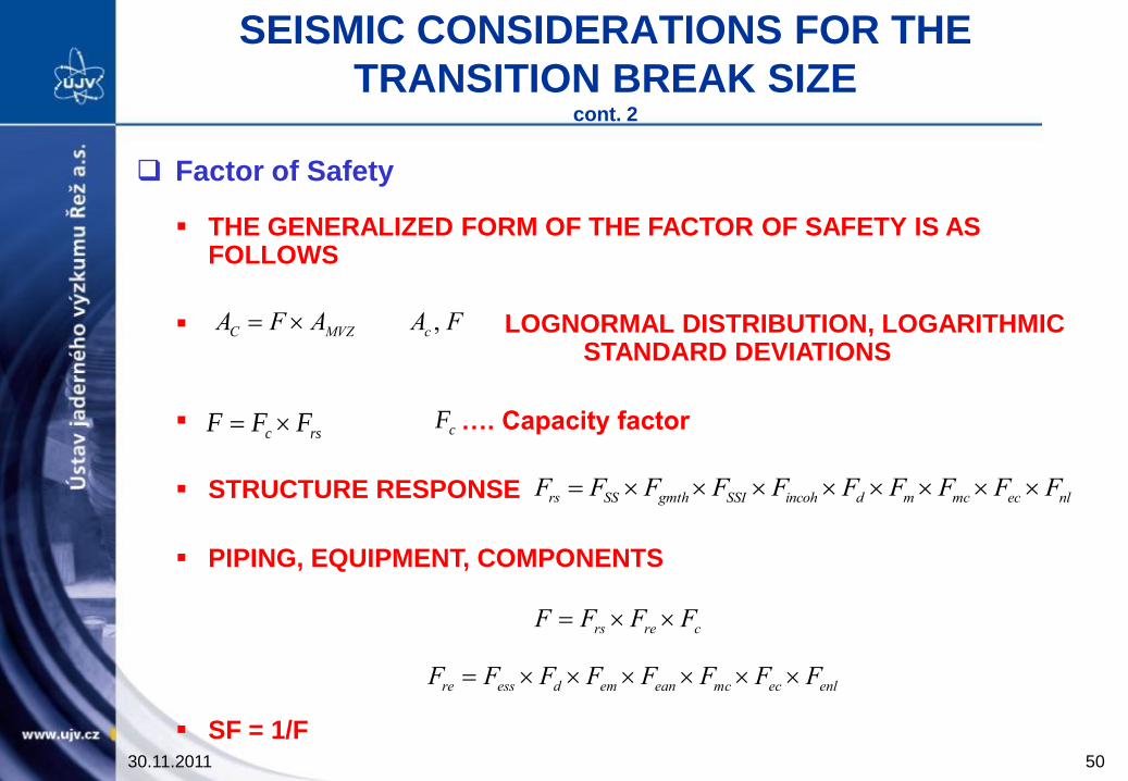
Factor of Safety
THE GENERALIZED FORM OF THE FACTOR OF SAFETY IS AS FOLLOWS
LOGNORMAL DISTRIBUTION, LOGARITHMIC STANDARD DEVIATIONS
…. Capacity factor
STRUCTURE RESPONSE
PIPING, EQUIPMENT, COMPONENTS
SF = 1/F
FAAFA cMVZC ,
rsc FFF
nlecmcmdincohSSIgmthSSrs FFFFFFFFFF
crers FFFF
enlecmceanemdessre FFFFFFFF
30.11.2011 50
cF

SEISMIC CONSIDERATIONS FOR THE
TRANSITION BREAK SIZE cont. 3
Estimates of Normalized Stress Ratios and Probability of
Exceedance
Hazard Curve for Plant of Interest Probability
Acceleration Acceleration
m s-2 g
Probability of
Exceedance
=
A/MVZPG
Corrected
Seismic
stresses
x SF x SSE
(N+Seismic
Value)/Sm
0,5 0,051 1,21 E-3 ..
..
..
1,0 0,102 4,1 E-4 ..
..
..
....
....
....
....
....
....
....
....
....
....
....
....
....
....
....
....
....
....
....
....
....
....
....
....
....
....
....
....
....
....
~ ~ ~ ~ ~ ~ ~
30.11.2011 51
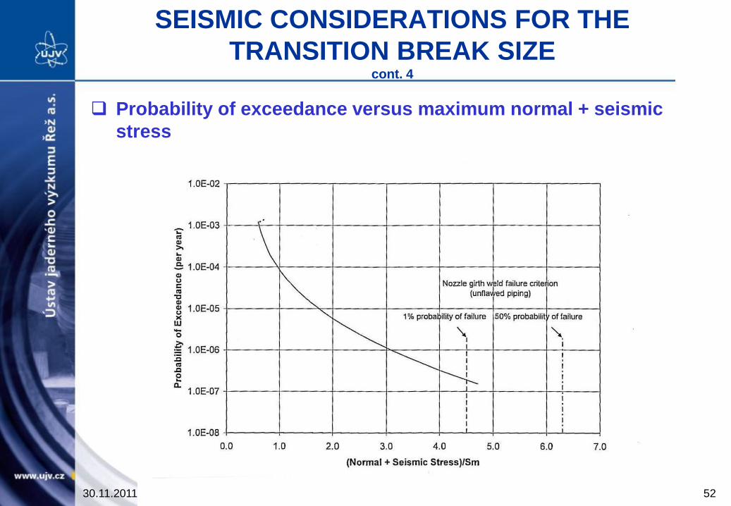
SEISMIC CONSIDERATIONS FOR THE
TRANSITION BREAK SIZE cont. 4
Probability of exceedance versus maximum normal + seismic
stress
30.11.2011 52

SEISMIC CONSIDERATIONS FOR THE
TRANSITION BREAK SIZE cont. 5
CONCLUSIONS
The US NCR has been considering revision of the regulatory
requirements for the ECCS
State of the art: ECCS shall be sized to provide adequate makeup water
to compensate LLOCA
Concept of the transition break size proposed
Methodology of evaluation of seismic effects presented
30.11.2011 53

www.ujv.cz
Thank you for your attention
30.11.2011 54