special products - amphenol aerospace
TRANSCRIPT

AMPHENOL CORPORATION Aerospace Operations Manufacturing Layout 40-60 Delaware St. SPECIAL PRODUCTS Part No. Sidney, NY 13838-1395 PR305 Quality Approval: Quality Standards ISSUE 2 HANEY 8/22/2005 - INDEX-
SPECIAL PRODUCTS SECTION Revision: 08/22/2005
PAGE 1 This Quality Standard applies unless otherwise specified by drawing or specification. PAGE 1 : INDEX PAGE 2 : DEFINITIONS PAGE 3 : DEFINITIONS (con't ) PAGE 4 : VISUAL AIDS OF WORKMANSHIP STANDARDS PAGE 5 : VISUAL AIDS OF WORKMANSHIP STANDARDS PAGE 6 : GLASS BEAD, HERMETIC SEAL PAGE 7 : HERMETIC CONNECTOR PAGE 8 : DIODE, UNITAB PAGE 9 : E CORES and FERRITES PAGE 10 : E CORES and FERRITES PAGE 11: BACKSHELL ACCESSORIES, SPACE STATION PAGE 12: BACKSHELL ACCESSORIES, SPACE STATION PAGE 13: MARKING and STAMPING PAGE 14: FOREIGN OBJECT / CONTAMINATION PAGE 15: CABLE: CABLE JACKET
Page 1

AMPHENOL CORPORATION Aerospace Operations Manufacturing Layout 40-60 Delaware St. SPECIAL PRODUCTS
PART NO.
Sidney, NY 13838-1395 PR305 Quality Approval: Quality Standards Operation No. Definitions
Revision 7/25/96 PAGE 2
Blisters/Pimples A condition that is the result of internal gas release or air pockets evidenced by the appearance of a bump. Chips Small nicks along edges of part or small pieces broken off from the edge. Closed Knit Line A visible material flow line having no perceptive depth. Color Uniformity Surface color varying in uniformity resulting in spots, blotches and striations of different color. Contamination An inclusion of foreign material detectable on the surface of the part. Cracks A fracture passing completely through the thickness or section of a part. Crazing Fine surface cracks appearing as a network of interconnecting hairline cracks on the surface. Cut Material severed or damaged as a result of piercing or slicing action with a sharp instrument or tool. Deformed A departure from the normal shape greater than the dimensional tolerance. Parts often deform out of round, out of square, twisted, warped, bent or flattened. Dent A depression with no removal of material or change in surface texture. Dry Spot An area on the surface of the part where reinforcement has not been wetted with resin, usually distinguished by the presence of loose fibers. Flash Excess material adhering to part.
Page 2
AMPHENOL CORPORATION Aerospace Operations Manufacturing Layout 40-60 Delaware St. SPECIAL PRODUCTS Part No. Sidney, NY 13838-1395 PR305 Quality Approval: Quality Standards Operation No. Definitions
Revision 7/25/96 PAGE 3
Gouges The result of scooping out of material by another object. Mutilation May consist of any combination of a gouge, cut, nick, tear, porosity and other abnormal material conditions that result in the part exhibiting a non unifrom appearance. Nicks Sharp surface indentation caused by impact of a foreign object. Parent material is normally displaced, seldom separated. Non-fill / Void An incomplete part due to insufficient material. Pit / Pinhole A small sharply defined hole in the surface of the part. Porosity Multiple pits or pin holes Scuff A mark caused by an abrasion which changes the surface smoothness or texture. Sink Marks A dimple like depression in surface of part. Surface Cracks A fracture on surface of part that does not go completely through thickness of part. Surface Discoloration An apparent surface inconsistency in material evidenced by the appearance of light to dark streaks. Tear Separation of material due to mechanical stress. Wire Marks Visible marks caused by the part having rested against the curing trays. Page 3

AMPHENOL CORPORATION Aerospace Operations Manufacturing Layout 40-60 Delaware St. SPECIAL PRODUCTS Part No. Sidney, NY 13838-1395 PR305 Quality Approval: Quality Standards Operation No. VISUAL AIDS OF WORKMANSHIP
STANDARDS Revision 7/25/96
PAGE 4 Separate visual aids for the following are available in the Quality Assurance and/or Gage Inspection (44) and shall be used in final acceptance of product. PART 44- Brush Connector, Flat Tips Cap, Protective, Wobble Broach Key way Cap, Protective, Burrs in Key way Clip Seating 44-178029 Connector, LJT Plug, Cracked & Chipped plating, Result of staking Contact, Burned During Anneal Contact, Burrs on OD Contact, Mutilated leaves Contact, Mutilated Sleeve Contact, Mutilated Wirewell Contact, Thin Wall Contact, Tool marks on OD Contact, 2 pc 44-157764 Contact, 2 pc, Hermetic 44-157790 Contact, 10-285443-2S & 10-285443-3s 44-183870 Contact, 21-33312-( ) Contact, Bonding 44-179287 Contact, Sleeve, Nicks on Sealing Surface Contact, spring Coupling Nut, Ratchet Spring Alignment Coupling nut, Ratchet Spring Straightness Disc & Clips, 48 & 217 Series Ferrite 44-178049 Grounding Fingers 44-178031 Hermetic Assembly 44-157784 Insert Exposed Fibers Insert, Torlon, Melted Tines Insert Torlon, Flash Molded Connector, Surface Cracks, 10-398209 &10-398213 Plating, Discoloration (Q-C52) Shell, Extrusion Marks on OD
Page 4
AMPHENOL CORPORATION

Aerospace Operations Manufacturing Layout 40-60 Delaware St. SPECIAL PRODUCTS Part No. Sidney, NY 13838-1395 PR305 Quality Approval: Quality Standards Operation No. VISUAL AIDS OF WORKMANSHIP
STANDARDS Revision 7/25/96
PAGE 5 Shell, Flange, Torn Material & Dings 44-157787 Shell, Ratchet Burrs Shell, Rollover Burrs in Key way Shell, Magna formed Shell and Coupling nut Assembly, 10-483755-( )G Shell and Ground Strap Assembly, Excessive Solder Shell and Ground strap Assembly, solder voids Socket 44-154789 Strap, Expansion 44-179288 Wafer, Chip on OD Wafer, Blank, Chips, Sprue, Excess Material 44-176697 Wave Washer 44-157783 Wirewell
Page 5
AMPHENOL CORPORATION

Aerospace Operations Manufacturing Layout 40-60 Delaware St. SPECIAL PRODUCTS Part No. Sidney, NY 13838-1395 PR305 Quality Approval: Quality Standards Operation No. GLASS BEAD, HERMETIC SEAL
Revision 7/25/96
PAGE 6 Acceptable Imperfections 1. Chips completely through lip less than .020 deep and less than .080 wide which do not invade "A" diameter 2. Surface chips or "craters" less than .020 wide in arrangement area and less than .080 wide outside arrangement area 3. Chips on edge of holes less than .015 wide 4. Chips in "A" diameter which do not cause bead weight tolerance to be exceeded
GLASS BEAD 10-184806/850 & OTHERS
Page 6
AMPHENOL CORPORATION Aerospace Operations Manufacturing Layout
40-60 Delaware St. SPECIAL PRODUCTS Part No. Sidney, NY 13838-1395 PR305 Quality Approval: Quality Standards Operation No. HERMETIC CONNECTOR
Revision 3/11/04
PAGE 7 Acceptable Imperfections 1. Contacts a. Gold at base of contact not in excess of 1/4 distance of contact to contact or contact to shell b. Carbon under plating not in excess of 1/3 length or 1/3 diameter of contact. Carbon exhibits a rough nodular appearance. c. Tin plate having no visible defects under 3X magnification max. d. Frosted and etched contacts exhibiting no more than a light frosted appearance. e. Contacts shall be free of burrs greater than .001 inch inside the socket wells, on the surface of the pins and inside the solder cups.
f. Resultant unplated area due to ‘wire marks’ from the plating procedure is permissible on the termination end of the contacts.
2. Glass a. Meniscus acceptable up to under the solder cup. b. Glass spatter on solder well up to under the solder cup. c. Foreign material in glass less than 1/4 distance contact to contact or contact to shell. d. Minor cracking located entirely in the meniscus. e. Letters must be complete, one incomplete or missing character provided contact is easily identifiable by surrounding characters. 3. Shell a. Shell must be completely plated with the exception of rack marks and unplated areas on rivets. b. Surface must be completely plated with the exception of rack marks and unplated areas on rivets. c. Tin reflow on shells must be smooth. Dull and shiny areas are acceptable. d. Porosity not visible with 3X magnification. e. OD must be bright and shiny after electropolish. ID may be frosted, however, all oxides must be removed. All internal O'ring requirements must be met.
Page 7
AMPHENOL CORPORATION Aerospace Operations Manufacturing Layout

40-60 Delaware St. SPECIAL PRODUCTS Part No. Sidney, NY 13838-1395 PR305 Quality Approval: Quality Standards Operation No. DIODE, UNITAB
Revision 7/25/96 PAGE 8
Acceptable Imperfections 1. Slightly rounded corners or small chips on corners having no significant depth 2. Small chips on edges having no significant depth
Page 8
AMPHENOL CORPORATION Aerospace Operations Manufacturing Layout 40-60 Delaware St. SPECIAL PRODUCTS Part No.

Sidney, NY 13838-1395 PR305 Quality Approval: Quality Standards Operation No. E CORES AND FERRITES
Revision 6/26/97
PAGE 9 SCOPE: This Quality standard applies to E Cores and Ferrite Sleeves used on the ARINC 629 Current Mode Coupler. It applies to E Cores and Ferrites as received from the supplier and during assembly and final inspection of Current Mode Couplers. Visual examination shall be without aid of magnification, except 10X may be used to verify size or extent of the condition. ***************************************************************** Definitions: REFERENCE DIMENSION: The smallest dimension of the surface under consideration. ***************************************************************** QUALITY STANDARDS: (See corresponding flag notes on sketches below). (NOTE: Standards are based upon Industry Standard: Magnetic Materials Producers Association; MMPA Standard UEI 310, Revised September 1988). 1. Chips with their largest dimension less than or equal to 1/3 of the reference dimension are acceptable on the mating surfaces. 2. No E Core can have more than 3 chips on the mating surfaces. 3. No ferrite can have more than 2 chips. 4. Pits and surface voids are to be considered as chips. 5. No surface porosity is allowed on E Core mating surfaces. 6. Cracks that are less than 1/2 of the reference dimension are allowed. The sum total of crack lengths from each surface shall not exceed 1/2 the reference dimension. 7. Ferrites that are excessively warped resulting in restricted cable movement are unacceptable. 8. All mating surfaces of E Cores shall be free of dirt or any foreign matter. Any stains, discoloration or surface crazing that does not interfere mechanically or electrically is allowed.
Page 9
AMPHENOL CORPORATION Aerospace Operations Manufacturing Layout 40-60 Delaware St. SPECIAL PRODUCTS Part No. Sidney, NY 13838-1395 PR305

Quality Approval: Quality Standards Operation No. E CORES AND FERRITES
Revision 6/26/97
PAGE 10
PAGE 10 AMPHENOL CORPORATION
Aerospace Operations Manufacturing Layout 40-60 Delaware St. SPECIAL PRODUCTS Part No. Sidney, NY 13838-1395 PR305 Quality Approval: Quality Standards Operation No.
BACKSHELL ACCESSORIES,
SPACE STATION Revision
9/5/1996 PAGE 11
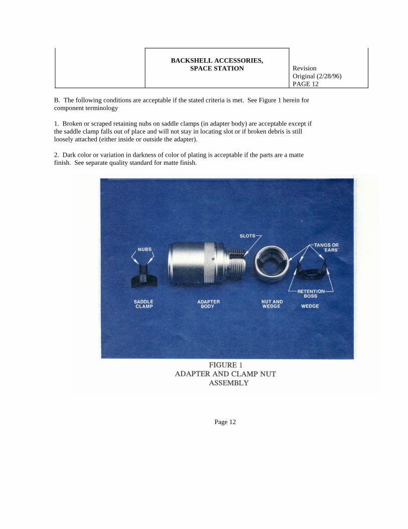
A1. The following conditions are acceptable if the backshell accessory functions properly when the stated actions are taken. See Figure 1 herein for component terminology. 1. Rear clamp nut hangs up or binds on the wedge when the nut is being completely removed. (Especially after several removals.) To help prevent the wedge from binding and reduce the condition where the wedge is either dislocated or completely dislodged, it sometimes helps to thread the nut forward as soon as the wedge begins to bind up. The wedge can also sometimes be jarred or pushed back into place which will reduce the binding action. In these cases when the wedge is free, once again continue to uncouple the nut. It may require several forward coupling and uncoupling cycles to get the nut off freely. When the binding does continue until the nut is removed and the wedge has become either dislocated (partially out of clamp nut) or dislodged completely from nut, the following installation is recommended: DISLOCATED: Hold clamp nut and turn the wedge clockwise, using the wedge ears or tangs, back into the nut until the retention bosses are in the undercut of the nut. DISLODGED: To re-install the wedge, depress the two tangs inward while pushing wedge into the I.D. thread of the nut. Turn tangs clock-wise back into the nut until the retention bosses are in the undercut of the nut. 2. Difficult to start assembly of clamp nut (size 16 in particular) due to short tangs; when nut is completely removed from backshell. Before starting clamp nut on adapter body check nut to be sure the wedge is in place and on center with the retention bosses in the undercut. Line up tangs with the slots in the adapter body and thread on to adapter. NOTE: "The tang alignment to slots is especially critical to parts that are not on a cable as there is nothing else to keep the wedge from freely rotating with the nut. Do not force the nut on." To achieve proper alignment it may be necessary to remove and/or wiggle the nut back and forth at the initial starting thread, while being sure the wedge tangs are in the adapter' slots, before fully threading the nut completely on. A2. For NZGA-FG()N()Z, -FX()N()Z, -LG()N()Z and -LX()N()Z backshells, the serration adapter sleeve is retained in an undercut by a threaded entry. It is acceptable for this sleeve to be loose and move freely within the undercut. Continued next page - Page 11 AMPHENOL CORPORATION
Aerospace Operations Manufacturing Layout 40-60 Delaware St. SPECIAL PRODUCTS Part No. Sidney, NY 13838-1395 PR305 Quality Approval: Quality Standards Operation No.
BACKSHELL ACCESSORIES,
SPACE STATION Revision
Original (2/28/96) PAGE 12
B. The following conditions are acceptable if the stated criteria is met. See Figure 1 herein for component terminology 1. Broken or scraped retaining nubs on saddle clamps (in adapter body) are acceptable except if the saddle clamp falls out of place and will not stay in locating slot or if broken debris is still loosely attached (either inside or outside the adapter). 2. Dark color or variation in darkness of color of plating is acceptable if the parts are a matte finish. See separate quality standard for matte finish.
Page 12

AMPHENOL CORPORATION Aerospace Operations Manufacturing Layout 40-60 Delaware St. SPECIAL PRODUCTS Part No. Sidney, NY 13838-1395 PR305 Quality Approval: Quality Standards Operation No. MARKING and STAMPING
( Including Blue and Red Bands) Revision 11/20/02
PAGE 13 Specification and drawing notes take precedent over this standard. A). General Requirement 1A). Any specified marking which is missing in whole or in part, faded, smeared, blurred, or dislodged to the extent that it cannot be readily identified from a distance of at least 6 inches with normal room lighting without the aid of magnification or with a viewer having a magnification no greater than 3x is unacceptable.* B). Interfacial Seals, Grommets, Inserts 1B). Slight distortion and/or faded characters are acceptable provided insert pattern can be easily determined and overall legibility is not impaired on interfacial seals or grommets. 2B). There shall not be two or more required consecutive or adjacent illegible or missing letters on interfacial seals or grommets. C). Part Number, Date Code, Lot Number 1C). If part of the identification number or letter is missing, or sufficiently distorted, so as to obscure the identity, the product is unacceptable D). Bands 1D). Bands on shells and coupling nuts should appear continous when viewed with normal room lighting without the aid of magnification at a distance of 3 feet. Minor scratches or fading only detectable under magnification or upon close examination will not be reason for rejection. * Note: refer to Mil-Std-202F Method 215J para.4.1.
PAGE 13

AMPHENOL CORPORATION Aerospace Operations Manufacturing Layout 40-60 Delaware St. Part No. Sidney, NY 13838-1395 PR305 Quality Approval: Quality Standards Operation No. FOREIGN OBJECT / CONTAMINATION
Revision: 01/23/2001 E:\Quality\Bh-ip500\FOD PAGE 14
VISIBLY CLEAN, SENSITIVE LEVEL: The presence of particulate and/or nonparticulate matter visible to the normal unaided ( except corrected vision ) eye at three feet under normal factory lighting is cause for rejection. Areas of suspected contamination may be examined at distances closer than specified for final verification. Definitions: Particulate: matter of miniature size with observable length, width and thickness. Nonparticulate: a film matter without definite dimension. (based upon the specification from NASA, Johnson Space Center: SN-C-0005 Rev.C)
Page 14

AMPHENOL CORPORATION Manufacturing Layout 40-60 Delaware St. SPECIAL PRODUCTS Part No. Sidney, NY 13838-1395 PR305 Quality Approval: Quality Standards Operation No. HANEY 8/15/2005
CABLES CABLE JACKETS
Revision: 08/18/2005
PAGE 15
REQUIREMENTS LISTED BELOW FOR CABLE JACKETS ALSO APPLY
TO THE INDIVIDUAL CONDUCTOR INSULATION. EACH CONDUCTOR INSULATION IS CONSIDERED AS AN INDIVIDUAL CABLE JACKET FOR THIS STANDARD.
1. CUT OR DAMAGED CABLE JACKETS IS AN UNACCEPTABLE CONDITION. 2. NON-CENTERED CABLE JACKET IN RELATION TO THE CONDUCTORS IS AN
UNACCEPTABLE CONDITION.
3. ANY SPECIFIED MARKING WHICH IS MISSING IN WHOLE OR IN PART, FADED, SMEARED, BLURRED OR DISLODGED TO THE EXTENT THAT IT CANNOT BE READILY IDENTIFED FROM A DISTANCE OF AT LEAST 6 INCHES WITH NORMAL ROOM LIGHTING WITHOUT AID OF MAGNIFICATION OR WITH A VIEWER HAVING A MAGNIFICATION NO GREATER THAN 3x IS UNACCEPTABLE. Note: Slight distortion and/or faded characters are acceptable provided the overall marking pattern or text can be easily determined and the overall legibility is not impaired.
4. CABLES TO BE FREE FROM CONTAMINENTS.
5. CABLE JACKET TO HAVE SMOOTH APPEARANCE WITHOUT OBJECTIONABLE
ROUGHNESS OR IRREGULARITIES. Note: Scuff marks in isolated areas are acceptable
6. CABLE JACKETS TO BE FREE FROM CRACKS, CRAZING, SCALING, CHATTERING MARKS, POROSITY OR GOUGES THAT MAY CAPTURE CONTAMINETS OR LEAD TO PREMATURE FAILURE OF THE JACKET INTEGRITY. .
Page 15