spec binder generic.indd 1 7/12/06 2:04:29 pmfiles.lutron.com/commercial/grafik_qs_complete.pdf ·...
TRANSCRIPT

Spec Binder Generic.indd 1 7/12/06 2:04:29 PM

System Solutions Lighting Control System O & M Manual
Job Name: Toll-Free 24/7 Technical Support Line: 1.800.523.9466
Job Number: Field Service Scheduling 1.800.523.9466 ext.4439
Warranty & Start-Up
Information


® Specif icat ion Submittal page
Job Name:
Job Number:
Model Numbers:
Lutron® Standard Limited Warranty Warranty
02.17.09
Lutron Standard Limited Warranty
Applies to all Lutron Products that are not purchased with Lutron Services Co., Inc. start-up.
This warranty gives you specific legal rights, and you may also have other rights which vary from state to state. Some states do not allow limitations on how long an implied warranty lasts, so the above limitation may not apply to you. Some states do not allow the exclusion or limitation of incidental or consequential damages, so the above limitation or exclusion may not apply to you.
For warranty service on returnable products (including Lutron ballasts), take the unit to the place of purchase or mail to:
Lutron 7200 Suter Rd. Coopersburg, PA 18036-1299 (send postage pre-paid for proper handling)
For warranty service on non-returnable products, contact Lutron Technical Support Center at 1-800-523-9466
Limited Warranty
Lutron warrants each new unit to be free from defects in materials and workmanship and to perform under normal use and service.
Lutron will, at its option, repair or replace any unit that is defective in materials or manufacture within one year after purchase. For Lutron ballasts, Lutron will repair or replace any unit that is defective in materials or manufacture within three years after purchase.
ThIS wARRAnTy IS In LIeu oF ALL oTheR exPReSS wARRAnTIeS, And The ImPLIed wARRAnTy oF meRChAnTAbILITy IS LImITed To one yeAR FRom PuRChASe. ThIS wARRAnTy APPLIeS onLy To LuTRon hARdwARe And doeS noT InCLude LuTRon SoFTwARe, LuTRon PRovIded SySTem SeRveRS, LAPToPS, PdAS, oR ComPuTeRS PuRChASed wITh LuTRon ConTRoL SySTemS. ThIS wARRAnTy doeS noT CoveR The CoST oF InSTALLATIon, RemovAL, oR ReInSTALLATIon, oR dAmAge ReSuLTIng FRom mISuSe, AbuSe, oR ImPRoPeR oR InCoRReCT RePAIR, oR dAmAge FRom ImPRoPeR wIRIng oR InSTALLATIon. ThIS wARRAnTy doeS noT CoveR InCIdenTAL, oR SPeCIAL dAmAgeS. The PuRChASeR ASSumeS And wILL hoLd hARmLeSS LuTRon In ReSPeCT oF ALL SuCh LoSS. LuTRon’S LIAbILITy on Any CLAIm FoR dAmAgeS ARISIng ouT oF oR In ConneCTIon wITh The mAnuFACTuRe, SALe, InSTALLATIon, deLIveRy, oR uSe oF The unIT ShALL neveR exCeed The PuRChASe PRICe oF The unIT.
Note - Although every attempt is made to ensure that catalog information is accurate and up-to-date, please check with Lutron before specifying or purchasing this equipment to confirm availability, exact specifications, and suitability for your application.
©2009 Lutron electronics Co., Inc.

® Specif icat ion Submittal page
Job Name:
Job Number:
Model Numbers:
Lutron® Warranty
02.17.09
Lutron Electronics Co., Inc. Commercial Systems Limited Warranty
Number of Years from Date of Start-up or Shipment,
as applicable
Percentage of Part Price Credited by Lutron
Hardware Ballasts
With Start-up
No Start-up
With Start-up
No Start-up
up to 1 100% 100% 100% 100%more than 1
but not more than 2100% 0% 100% 100%
more than 2 but not more than 3
50% 0% 100% 100%
more than 3 but not more than 5
50% 0% 100% 0%
more than 5 but not more than 8
25% 0% 0% 0%
more than 8 0% 0% 0% 0%
If any manufacturing defect exists in the Supplied Computer or Software during the one year period from the date of start-up by Lutron or a Lutron approved third party, or the date of shipment by Lutron if component was not purchased with Lutron start-up, so long as Customer promptly notifies Lutron of the defect, upon the return of the defective part(s) as to the Supplied Computer, if requested by Lutron, or Lutron determining that a defect exists as to the Software, Lutron will, at its option, either repair the defective part(s) or provide comparable replacement part(s).
Replacement parts for the System provided by Lutron or, at its sole discretion, an approved vendor may be new, used, repaired, reconditioned, and/or made by a different manufacturer.
CUSTOMER OBLIGATIONS TO MAINTAIN LIMITED WARRANTY
This warranty will be void, and Lutron will have no obligations under it unless Customer complies with all of the following:
1. The Supplied Computer must be installed and maintained in a secure location, within the
SCOPE
This limited warranty (“warranty”) covers Lutron (a) commercial lighting control system panels, controls, processor panels, wall box products, and other Lutron components (collectively, “hardware”), (b) ballasts supplied directly by Lutron (“ballasts”), (c) provided computer (“Supplied Computer”), and (d) commercial systems eLumen software (“Software” and, with the hardware, ballasts and Supplied Computer, the “System”). Customer acknowledges and agrees that use of (i) the System, or any part thereof, constitutes acceptance of all terms and conditions of this warranty and (ii) the Software is subject to the terms and conditions of Lutron’s Software License. Any subsequent addition to the System provided by Lutron will be governed by a separate warranty issued at the time of the purchase of the additional equipment.
The provisions of this warranty applicable to the Supplied Computer and Software will not apply to Systems that do not include these components.
LIMITED WARRANTY
Subject to the exclusions and restrictions and for the periods of time described in this warranty, Lutron warrants that the System will be free from manufac-turing defects. If any manufacturing defect exists in any hardware or ballast during the period of time identified below from the date of start-up completion by Lutron or a Lutron approved third party, or the date of shipment by Lutron if such component was not purchased with Lutron start-up, so long as Customer promptly notifies Lutron of the defect and, if requested by Lutron, upon the return of the defective part(s), Lutron will, at its option, either repair the defective part(s) or issue a credit to the Customer against the purchase price of comparable replacement part(s) purchased from Lutron as follows:
Commercial Systems Limited Warranty

® Specif icat ion Submittal page
Job Name:
Job Number:
Model Numbers:
Lutron® Warranty
02.17.09
temperature and relative humidity ranges specified in the documentation accompanying the Supplied Computer, and away from where it may be bumped, abused, or subjected to large amounts of dust or dirt.
2. The Supplied Computer must be connected to a reliable (and preferably generator or battery backed-up) power supply.
3. The Supplied Computer must be properly shutdown in the event of power loss to prevent damage to it or its data, either of which could prevent it from operating properly. Customer has sole responsibility to take all reasonable measures to prevent this from occurring.
4. no modification, alteration, adjustment or repair can be made to the Software except by, or at the express instruction of, Lutron.
5. The Software may not be used on any hardware except the Supplied Computer.
6. no third party software may be installed on the Supplied Computer.
Lutron does not warrant that the Software will operate in combination with any other software except as specified in the applicable Lutron docu-mentation. Customer acknowledges that its use of the Software may not be uninterrupted or error-free.
To ensure optimal operating conditions for the System, Lutron recommends that the Supplied Computer (1) not be connected to a power source that is also supplying power to a motor or other load that causes significant conducted emissions; (2) be located to permit easy access to it; and (3) be placed on a dedicated circuit.
EXCLUSIONS AND RESTRICTIONS
This warranty does not cover, and Lutron and its suppliers are not responsible for:
1. damage, malfunction or inoperability diagnosed by Lutron or a Lutron approved third party as caused by normal wear and tear, abuse, misuse, incor-rect installation, neglect, accident, interference or environmental factors, such as (a) use of incorrect
line voltages, fuses or circuit breakers; (b) failure to install, maintain and operate the System pursuant to the operating instructions provided by Lutron and the applicable provisions of the national electrical Code and of the Safety Standards of underwriter’s Laboratories; (c) use of incompatible devices or accessories; (d) improper or insufficient ventilation; (e) unauthorized repairs or adjustments; (f) vandal-ism; (g) failure to comply with the Customer obliga-tions listed above; (h) an act of god, such as fire, lightning, flooding, tornado, earthquake, hurricane or other problems beyond Lutron’s control; (i) mov-ing the Supplied Computer to another geographic location; (j) a virus or computer hacker; or (k) failure to maintain equipment under specified ambient temperature.
2. on-site labor costs to diagnose issues with, and to remove, repair, replace, adjust, reinstall and/or reprogram the System or any of its components.
3. Components and equipment external to the System, such as, lamps; non-Lutron ballasts; oem supplied Lutron ballasts, sockets, and fixtures; fixture wiring between ballasts and lamps; building wiring between the dimmer panels and lamps and between the controls and the control or dimmer panels; audio-visual equipment; and non-Lutron time clocks and motion detectors.
4. The cost of repairing or replacing other property that is damaged when the System does not work properly, even if the damage was caused by the System.
5. Any loss of software, including the Software, or data. Customer has sole responsibility to properly back up all data on the Supplied Computer’s hard disk drive and on any other storage device(s) in the System.
6. Repairs required due to malfunctions caused by non-Lutron supplied software.
exCePT AS exPReSSLy PRovIded In ThIS wARRAnTy, TheRe ARe no exPReSS oR ImPLIed wARRAnTIeS oF Any TyPe, InCLudIng Any ImPLIed wARRAnTIeS oF FITneSS FoR A PARTICuLAR PuRPoSe oR meRChAnTAbILITy.
Commercial Systems Limited Warranty

® Specif icat ion Submittal page
Job Name:
Job Number:
Model Numbers:
Lutron® Warranty
02.17.09
Commercial Systems Limited Warranty
LuTRon doeS noT wARRAnT ThAT The SyS-Tem wILL oPeRATe wIThouT InTeRRuPTIon oR be eRRoR FRee.
no LuTRon AgenT, emPLoyee oR RePReSen-TATIve hAS Any AuThoRITy To bInd LuTRon To Any AFFIRmATIon, RePReSenTATIon oR wARRAnTy ConCeRnIng The SySTem. unLeSS An AFFIRmATIon, RePReSenTATIon oR wARRAnTy mAde by An AgenT, emPLoyee oR RePReSenTATIve IS SPeCIFICALLy InCLuded heReIn, oR In STAndARd PRInTed mATeRIALS PRovIded by LuTRon, IT doeS noT FoRm A PART oF The bASIS oF Any bARgAIn beTween LuTRon And CuSTomeR And wILL noT In Any wAy be enFoRCeAbLe by CuSTomeR.
In no evenT wILL LuTRon oR Any oTheR PARTy be LIAbLe FoR exemPLARy, ConSe-QuenTIAL, InCIdenTAL oR SPeCIAL dAmAgeS (InCLudIng, buT noT LImITed To, dAmAgeS FoR LoSS oF PRoFITS, ConFIdenTIAL oR oTheR InFoRmATIon, oR PRIvACy; buSIneSS InTeRRuPTIon; PeRSonAL InJuRy; FAILuRe To meeT Any duTy, InCLudIng oF good FAITh oR oF ReASonAbLe CARe; negLIgenCe, oR Any oTheR PeCunIARy oR oTheR LoSS whATSo-eveR), noR FoR Any RePAIR woRK undeRTAK-en wIThouT LuTRon’S wRITTen ConSenT ARISIng ouT oF oR In Any wAy ReLATed To The InSTALLATIon, deInSTALLATIon, uSe oF oR InAbILITy To uSe The SySTem oR oTheR-wISe undeR oR In ConneCTIon wITh Any PRovISIon oF ThIS wARRAnTy, oR Any AgRee-menT InCoRPoRATIng ThIS wARRAnTy, even In The evenT oF The FAuLT, ToRT (InCLudIng negLIgenCe), STRICT LIAbILITy, bReACh oF ConTRACT oR bReACh oF wARRAnTy oF LuTRon oR Any SuPPLIeR, And even IF LuTRon oR Any oTheR PARTy wAS AdvISed oF The PoSSIbILITy oF SuCh dAmAgeS.
noTwIThSTAndIng Any dAmAgeS ThAT CuS-TomeR mIghT InCuR FoR Any ReASon whAT-SoeveR (InCLudIng, wIThouT LImITATIon, ALL dIReCT dAmAgeS And ALL dAmAgeS LISTed
Above), The enTIRe LIAbILITy oF LuTRon And oF ALL oTheR PARTIeS undeR ThIS wARRAnTy on Any CLAIm FoR dAmAgeS ARISIng ouT oF oR In ConneCTIon wITh The mAnuFACTuRe, SALe, InSTALLATIon, deLIveRy, uSe, RePAIR, oR RePLACemenT oF The SySTem, oR Any AgReemenT InCoRPoRATIng ThIS wARRAnTy, And CuSTomeR’S SoLe Remedy FoR The FoRegoIng, wILL be LImITed To The AmounT PAId To LuTRon by CuSTomeR FoR The SySTem. The FoRegoIng LImITATIonS, exCLuSIonS And dISCLAImeRS wILL APPLy To The mAxImum exTenT ALLowed by APPLICAbLe LAw, even IF Any Remedy FAILS ITS eSSenTIAL PuRPoSe.
TO MAKE A WARRANTY CLAIM
To make a warranty claim, promptly notify Lutron within the warranty periods described above by calling the Lutron Technical Support Center at 1-800-523-9466. Lutron, in its sole discretion, will determine what action, if any, is required under this warranty. most System problems can be corrected over the phone through close cooperation between Customer and a technician. To better enable Lutron to address a warranty claim, have the System’s serial and model numbers, its current operating system version, and the brand names and models of any peripheral devices (such as a modem) used with the System available when making the call. Let the technician know what error message you get; when it occurs; what you were doing when the error occurred; and what steps you have already taken to solve the problem. Listen carefully to the technician and follow the technician’s directions.
If Lutron, in its sole discretion, determines that an on-site visit or other remedial action is necessary, Lutron may send a Lutron Services Co. representa-tive or coordinate the dispatch of a representative from a Lutron approved vendor, to Customer’s site, and/or coordinate a warranty service call between Customer and a Lutron approved vendor. All on-site labor costs incurred to diagnose any problems with

® Specif icat ion Submittal page
Job Name:
Job Number:
Model Numbers:
Lutron® Warranty
02.17.09
Commercial Systems Limited Warranty
the System and to repair, replace or adjust (at Lutron’s option) the System to restore it to normal operation will be paid by customer at the then current service price unless covered by a Lutron Services Co. Support and maintenance Plan.
REMOTE ACCESS
A dedicated analog phone line should be installed for the Supplied Computer to allow Lutron to remotely administer, troubleshoot, and support the System. Lutron does not recommended plugging the Supplied Computer into the analog phone line until
asked to do so by Lutron support personnel. during such support calls, Customer should disconnect the Supplied Computer from Customer’s local LAn. Lutron expressly disclaims all liability due to local LAn problems or if the phone line is connected to the Supplied Computer at any other time. Customer retains all responsibility for ensuring the security of the Supplied Computer from unauthorized access.
For more information, including preventative maintenance steps, see the users guide provided by the Lutron approved vendor of, and included with, the Supplied Computer.

® Specif icat ion Submittal page
Job Name:
Job Number:
Model Numbers:
Lutron®
02.17.09
1-Visit Start-up
Description
The 1-visit Start-up package includes one on-site start-up visit and extends the limited warranty for your integrated lighting system.
Field Start-up – A Lutron Services Company engineer will perform an on-site system inspection, start-up the system, and train facilities personnel on system operation and maintenance. This includes the cost of travel.
Visit Summary:
• Installation verification• wiring verification – power and low voltage• energizing the low voltage and enabling dimming
for the system• verification of lighting loads • System programming• Training
Additional Information
Replaces the Standard Limited warranty with the Lutron electronics Co., Inc. Commercial Systems Limited warranty. Also includes two consecutive 1-year Support and maintenance Plans. up to eight additional years of coverage can be purchased.
extends limited warranty for Lutron ballasts from 3 years to 5 years, if start-up is purchased for the ballasts.
24-hour/7-days a week toll-free telephone support (1-800-523-9466).
Refer to the Lutron electronics Co., Inc. Commercial Systems Limited warranty pages for limitations, exclusions, and any other details pertaining to what is covered by this warranty.
1-Visit Start-up Service

® Specif icat ion Submittal page
Job Name:
Job Number:
Model Numbers:
Lutron®
02.17.09
Support and Maintenance Plan - Silver Level (INIT)
Support and Maintenance Plan - Silver Level (INIT) (LSC-SILV-CS-IN-1, LSC-SILV-CS-IN-2)
• Remote Access Support - diagnostics and programming for systems with that capability (analog telephone line connection required, must be provided by system owner).
• 24-hour/7-days a week toll-free telephone support (1-800-523-9466).
Description
• Includes 1-year Support and maintenance Plan with system purchase and start-up, and commences on date of start-up completion.
• Covers on-site parts and labor, telephone technical support, and remote diagnostics
Service

® Specif icat ion Submittal page
Job Name:
Job Number:
Model Numbers:
Lutron® Warranty
02.17.09
Terms and Conditions of Lutron Services Co., Inc. Support and Maintenance Plans
This Agreement between Lutron Services Co., Inc. (“LSC”) and Customer provides parts and labor coverage for the Lutron electronics Co., Inc. (“Lutron”) Integrated Lighting Control System (“ILCS”) pur-chased on this bill of material. Parts and labor are covered at 100%, as further specified below.
1. The Silver Plan CoveRS:
• The diagnosis of problems with the Lutron ILCS and the repairs and adjustments necessary to restore the ILCS to normal operation are subject to the limitations described below. visits will occur during normal business hours monday through Friday.
• Replacement parts, new or rebuilt, at LSC’s option.
• Four (4) hours of remote programming annually, for systems with that capability.
• Remote diagnostics, for systems with that capability.
• unlimited Lutron Technical Support (1-800-523-9466).
2. Additionally, the gold & Platinum Plans CoveR:
• An annual ILCS Checkup which can include:
a) an evaluation to verify that the ILCS is working properly
b) verification that panels have not been over-loaded in the course of building relamping or renovation
c) training of users on operation and maintenance of the ILCS
• For Trouble Calls, LSC will use commercially reasonable efforts to be at the Customer’s site within 24 hours (for Platinum customers) or 72 hours (for gold customers) of receipt of the request.
3. Service Procedures
• To schedule a visit, call 610-282-3800 and request to be connected to Field Service Scheduling.
• LSC representatives will perform service in compliance with security and other instructions provided by the Customer.
• LSC will respect the Customer’s need for confi-dentiality and will utilize job-specific information only as needed to complete the service visit.
• ILCS Checkups (for gold and Platinum custom-ers) will occur during normal business hours monday through Friday. They must be scheduled at least two weeks in advance.
• Customer agrees to allow LSC prompt and sufficient access to Customer’s facility and to provide reasonable information and assistance to the LSC representatives to expedite the performance of service.
• Customer agrees that all LSC service must be done in compliance with LSC’s safety proce-dures, which may include temporarily disabling or de-energizing the ILCS and other equipment connected to the ILCS.
• LSC will provide a certificate of insurance upon request of Customer.
4. This plan doeS noT CoveR:
• damage or malfunctions diagnosed by LSC as due to abuse, misuse, or accident, such as: use of incorrect line voltage, fuses or protection devices; failure to follow operating and mainte-nance instructions provided by Lutron or LSC; failure to comply with national or local electrical codes; unauthorized repairs/adjustments; vandal-ism or theft; fire, flood, “Acts of god”, or other problems beyond LSC’s control.
• non-Lutron components and equipment such as: lamps; non-Lutron ballasts, sockets, and fixtures; fixture wiring between ballasts and lamps; build-ing wiring between ILCS elements; audio-visual
Terms and Conditions of Support and Maintenance Plans

® Specif icat ion Submittal page
Job Name:
Job Number:
Model Numbers:
Lutron® Warranty
02.17.09
equipment; non-Lutron timeclocks and motion detectors; and Local Area networks.
• Labor costs to remove and reinstall fixtures and/or ballasts.
• desktop, Laptop, or Server hardware and software.
• Repairs or adjustments to Lutron ILCS required as a result of (i) malfunctions caused by non-Lutron supplied equipment, (ii) software that is connected to or used with the ILCS, or (iii) programming changes made by anyone other than LSC.
5. warranties
• LSC makes no warranty, either express or im-plied, including, but not limited to, any implied warranties of merchantability and fitness for a particular purpose
• For ILCS components that may be covered by product-specific warranties, LSC will coordinate the processing of any warranty claims.
6. Limitation of Remedy
• CuSTomeR’S exCLuSIve Remedy And LSC’S enTIRe, CoLLeCTIve LIAbILITy In ConTRACT, ToRT oR oTheRwISe, undeR ThIS AgRee-menT IS The RePAIR oF The deFeCTIve ILCS In ACCoRdAnCe wITh ThIS AgReemenT. IF LSC IS unAbLe To mAKe SuCh RePAIR, CuSTomeR’S exCLuSIve Remedy And LSC’S enTIRe LIAbILITy wILL be The PAymenT oF ACTuAL dAmAgeS noT To exCeed The ChARge PAId by CuSTomeR FoR one yeAR oF SeRvICe undeR ThIS AgReemenT. undeR no CIRCumSTAnCeS wILL LSC be LIAbLe To CuSTomeR oR Any oTheR PeRSon FoR Any dAmAgeS, InCLudIng, wIThouT LImITATIon, Any IndIReCT, InCIden-TAL, SPeCIAL, oR ConSeQuenTIAL dAmAgeS, exPenSeS, CoSTS, PRoFITS, LoST SAvIngS oR eARnIngS, LoST oR CoRRuPTed dATA, oR oTheR LIAbILITy ARISIng ouT oF oR ReLATed To ThIS AgReemenT, oR ouT oF The InSTALLATIon, deInSTALLATIon, uSe oF oR InAbILITy To uSe The SySTem.
• ThIS AgReemenT gIveS CuSTomeR SPeCIFIC LegAL RIghTS And CuSTomeR mAy hAve oTheR RIghTS ThAT vARy FRom STATe To STATe. Some STATeS do noT ALLow The exCLuSIon oR LImITATIon oF (i) InCIdenTAL oR ConSeQuenTIAL dAmAgeS oR (ii) ImPLIed wARRAnTIeS, So The Above mAy noT APPLy.
• Customer shall not bring legal action related to the services being provided hereunder more than two years after the cause of action arose unless otherwise provided by local law without the possibility of contractual waiver or limitation.
• LSC shall not be responsible for any delay or failure to perform its responsibilities under this Agreement that results from problems outside the control of LSC such as: permit or visa require-ments; strikes or work stoppage; fires, floods, “Acts of god”, wars, or force majeures; and transportation disruptions.
• with regard to any services that are not within the coverage of this Agreement, please contact LSC for service pricing and availability.
7. Taxes
• Customer agrees to pay all taxes (or reimburse LSC for all amounts paid or payable by LSC in discharge of these taxes) arising from this Agreement including state and local sales and use taxes, regardless of designation.
8. Term; Termination
• The term of this Agreement shall commence on the date of start-up completion and shall continue for the number of one-year terms purchased on the bill of material.
• default: LSC may terminate this Agreement if Customer remains in default of any material term or condition of this Agreement ten days after LSC gives Customer written notice of the default.
• unnecessary Service Calls: If Customer requests service on more than two (2) occasions in any one year for problems that are diagnosed by LSC as non-covered problems, LSC may terminate this Agreement by providing Customer with 30 days notice of termination.
Terms and Conditions of Support and Maintenance Plans

® Specif icat ion Submittal page
Job Name:
Job Number:
Model Numbers:
Lutron® Warranty
02.17.09
9. miscellaneous
• entire Agreement: This Agreement is the complete agreement between Customer and LSC regarding the services provided hereunder, and replaces any prior oral or written communications between Customer and LSC regarding such services. none of LSC’s employees or agents may orally vary the terms and conditions of this Agreement. Any modification of this Agreement must be signed in writing by authorized represen-tatives of Customer and LSC.
• Additional Remedies: This Agreement affords Customer specific legal rights. Customer may have additional legal rights that vary from state to state. This Agreement is not a warranty. The ILCS may come with a limited warranty from Lutron or third party manufacturers of products distributed by Lutron. Please consult those warranties for specific rights and remedies.
• Severability: If any part of this Agreement is held to be invalid or unenforceable, it will not affect the validity or enforceability of the rest of the Agree-ment. without further action of the parties, that part will be reformed to the minimum extent necessary to make it valid and enforceable.
• waiver of Rights: LSC’s failure to exercise, delay in exercising, or single or partial exercise of any right, power, or privilege under this Agreement shall not operate to waive or preclude LSC’s right to exercise such rights, power, or privileges.
• Send notices to: Lutron Services Co., Inc., Attn: director of Field Service, 7200 Suter Road, Coopersburg, PA 18036, cc: Legal dept.
Terms and Conditions of Support and Maintenance Plans

® Specif icat ion Submittal page
Job Name:
Job Number:
Model Numbers:
Lutron®
02.17.09
Contact List Warranty/Service
Internet: www.lutron.come-mail: [email protected]
WORLD HEADQUARTERSUSA
Lutron electronics Co., Inc.7200 Suter Road, Coopersburg, PA 18036-1299TeL +1.610.282.3800FAx +1.610.282.1243Toll-Free 1.888.LuTRon1Technical Support 1.800.523.9466
north and South America Technical hotlinesuSA, Canada, Caribbean: 1.800.523.9466mexico: +1.888.235.2910Central/South America: +1.610.282.6701
EUROPEAN HEADQUARTERSUnited Kingdom
Lutron eA Ltd.6 Sovereign Close, London, e1w 3JF united KingdomTeL +44.(0)20.7702.0657FAx +44.(0)20.7480.6899FReePhone (uK) 0800.282.107Technical support +44.(0)20.7680.4481
Lutron Contacts for all Warranties and Support and Maintenance Plans
ASIAN HEADQUARTERSSingapore
Lutron gL Ltd.15 hoe Chiang Road, #07-03 euro Asia Centre, Singapore 089316TeL +65.6220.4666FAx +65.6220.4333
Asia Technical Hotlines
northern China: 10.800.712.1536Southern China: 10.800.120.1536hong Kong: 800.901.849Indonesia: 001.803.011.3994Japan: +81.3.5575.8411macau: 0800.401Singapore: 800.120.4491Taiwan: 00.801.137.737Thailand: 001.800.120.665853other countries: +65.6220.4666

R
Job Name:
Job Number:
PageSPECIF ICATION SUBMITTAL
3,4k-1 01.09.08
Submittal PackageLighting Control SystemSystem Solutions
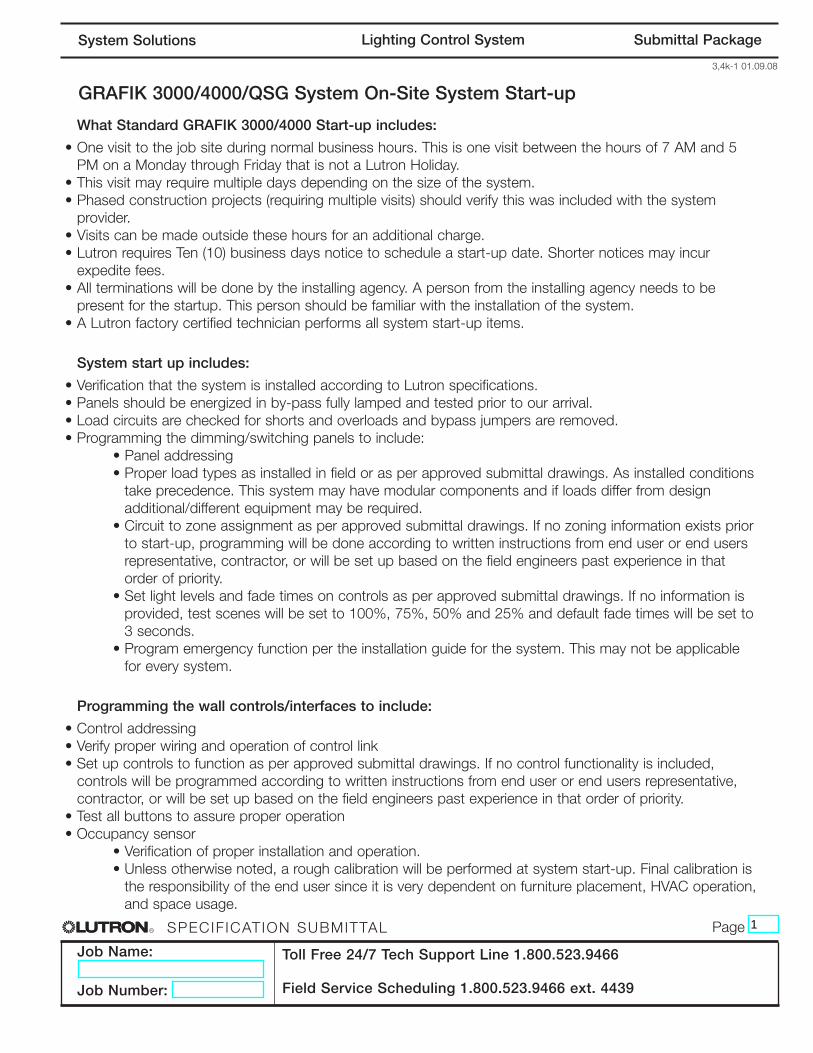
GRAFIK 3000/4000/QSG System On-Site System Start-up
What Standard GRAFIK 3000/4000 Start-up includes:
• One visit to the job site during normal business hours. This is one visit between the hours of 7 AM and 5PM on a Monday through Friday that is not a Lutron Holiday.
• This visit may require multiple days depending on the size of the system. • Phased construction projects (requiring multiple visits) should verify this was included with the system
provider. • Visits can be made outside these hours for an additional charge. • Lutron requires Ten (10) business days notice to schedule a start-up date. Shorter notices may incur
expedite fees.• All terminations will be done by the installing agency. A person from the installing agency needs to be
present for the startup. This person should be familiar with the installation of the system.• A Lutron factory certified technician performs all system start-up items.
System start up includes:
• Verification that the system is installed according to Lutron specifications.• Panels should be energized in by-pass fully lamped and tested prior to our arrival.• Load circuits are checked for shorts and overloads and bypass jumpers are removed.• Programming the dimming/switching panels to include:
• Panel addressing• Proper load types as installed in field or as per approved submittal drawings. As installed conditions
take precedence. This system may have modular components and if loads differ from designadditional/different equipment may be required.
• Circuit to zone assignment as per approved submittal drawings. If no zoning information exists priorto start-up, programming will be done according to written instructions from end user or end usersrepresentative, contractor, or will be set up based on the field engineers past experience in thatorder of priority.
• Set light levels and fade times on controls as per approved submittal drawings. If no information isprovided, test scenes will be set to 100%, 75%, 50% and 25% and default fade times will be set to3 seconds.
• Program emergency function per the installation guide for the system. This may not be applicablefor every system.
Programming the wall controls/interfaces to include:
• Control addressing• Verify proper wiring and operation of control link• Set up controls to function as per approved submittal drawings. If no control functionality is included,
controls will be programmed according to written instructions from end user or end users representative,contractor, or will be set up based on the field engineers past experience in that order of priority.
• Test all buttons to assure proper operation• Occupancy sensor
• Verification of proper installation and operation. • Unless otherwise noted, a rough calibration will be performed at system start-up. Final calibration is
the responsibility of the end user since it is very dependent on furniture placement, HVAC operation,and space usage.
Toll Free 24/7 Tech Support Line 1.800.523.9466
Field Service Scheduling 1.800.523.9466 ext. 4439
1

R
Job Name:
Job Number:
PageSPECIF ICATION SUBMITTAL
3,4k-2 01.09.08
Submittal PackageLighting Control SystemSystem Solutions
• Photocell • Verification of proper installation and operation. • Unless otherwise noted a rough calibration will be performed at system start-up. Final calibration is
the responsibility of the end user since it is very dependent on furniture placement, windowtreatments, outside weather conditions and space usage.
• Time clock set up• Lutron will set up the system location, daylight savings, and time of day preparation for event
programming.• Lutron will set up time clock events as per the approved submittal drawings or written instructions
from end user or end users representative, contractor in that order of priority. • In lieu of instructions, the time clock will not be programmed.
Items not included in standard on-site startup:
• Lutron service technicians will not perform work on non-Lutron equipment. Lutron will work with othermanufacturers on integration of equipment by others.
• Programming or any other changes that are requested to be performed counter to the approved submittaldrawings must be approved in writing via the proper channels.
• Field wiring changes or corrections that delay the startup process such that additional time is required forLutron to complete the startup in the allotted time will result in additional charges.
• Replacement of controls damaged due to miss-wires or incorrect installation or any other related issue notcovered under the Lutron warranty is the responsibility of the installer.
• Reprogramming of any functions after initial programming and sign-off.
End user training on overall system operation. Typical training agenda listed below:
• This system is not typically sold with a separate visit for the training of the end user. Check with purchasingagent if this is required.
• It is the responsibility of the person scheduling the startup to ensure the appropriate end users are present forsystem training. Lutron typically does not have these contacts.
• Additional charges will apply if a separate visit is required for training the end user.• Video media is not provided by Lutron for training sessions. This may be provided by “others” for turnover to
the end user or job site documentation.• System demonstration and sign-off by the end user.
Additional items that are not included with standard startup, but may be purchased – check yourquote to verify an item has been included with your quote. The quantity of the items listed below onthe BOM will determine how many days are included with this item.
• LSC-AF-VISIT. Aim and focus visit with design team or end user. This visit is typically coordinated bythe construction team, that includes designers, Lutron, and end user to set up light levels and adjustfixtures.
• LSC-SYSOPT. System optimization visit with end user. This visit is coordinated by the EC or end userto optimize the system performance to specific project details.
• LSC-WALK. Start-up agent or design team walk-through visit. The construction team and the agentrequiring the walk-through coordinate this visit. This visit is for any type of additional walk-through thatis required for job completion.
Toll Free 24/7 Tech Support Line 1.800.523.9466
Field Service Scheduling 1.800.523.9466 ext. 4439
2

R
Job Name:
Job Number:
PageSPECIF ICATION SUBMITTAL
3,4k-3 01.09.08
Submittal PackageLighting Control SystemSystem Solutions
• LSC-SILV/GOLD/PLAT-IW. These are extended warranty part numbers for the system per thespecification. Warranty information is supplied within the submittal documentation.
• LSC-TRAINING. This visit is for additional time on the job for training the end user. The EC or the enduser typically coordinates this visit.
• LSC-AH-SU. After hours start-up. If normal business hours are not acceptable for start-up, after hoursstart-up can be purchased.
Additional items listed below may be charged for jobsites that are scheduled for start-up, but notready when field service engineer arrives.
• LSC-NS-TRAVEL. Non standard travel arrangements• LSC-SITE-RDY-CHG. Site ready charge. Jobsite not ready.
Toll Free 24/7 Tech Support Line 1.800.523.9466
Field Service Scheduling 1.800.523.9466 ext. 4439
3

R
Job Name:
Job Number:
PageSPECIF ICATION SUBMITTAL
3,4k-4 01.09.08
Submittal PackageLighting Control SystemSystem Solutions
GRAFIK Eye Family 3000/4000/QSG SeriesGRAFIK Eye 4000 Family Series is an architectural preset lighting control product that creates functionalspaces through various lighting combinations. It utilizes low voltage digital controls that communicate withhigh voltage dimming and switching panels. The digital nature of the product allows the user to quickly andeasily select lighting scenes to align with the use of the space. These scenes can be reprogrammed as theneeds of the space change.
GRAFIK Eye 3000 Family Series is an architectural preset lighting control product that creates functionalspaces through various lighting combinations. It utilizes low voltage digital controls that communicate withhigh voltage digital controls. The digital nature of the product allows the user to quickly and easily selectlighting scenes to align with the use of the space. These scenes can be reprogrammed as the needs of thespace change.
4000 Training Visit – Typical Agenda (duration – approximately 1 hour):
• Review system with end-user (control location and function).• Discuss system model numbers• Discuss Lutron lexicon – what is a zone, scene, fade rate• Review GRAFIK EYE main controller functions
o How to set a sceneo How to adjust fade rateo How to make a temporary sceneo How to set light loadso How to change light levels
• Special save modes and when to use each• Review all accessory controls functions
o How to address accessory controlso Programming scenes from accessory controls
• Review dimmer panel(s) (for G4000 system, N/A for G3000 systems)o Bypassing a G4000o Spare dimmer cards
• Load schedule • Troubleshooting the system• Preventive maintenance• Liaison software (if applicable)• Timeclock options
o Real Timeo Astronomic
NOTE: All topics may not be relevant to every system
Toll Free 24/7 Tech Support Line 1.800.523.9466
Field Service Scheduling 1.800.523.9466 ext. 4439
4

service and support guide | lighting control system
serv
ice
reco
rdT
his
info
rmat
ion
will
hel
p u
s as
sist
yo
u w
hen
you
cont
act
Lutr
on:
Job
Num
ber
(typi
cally
on
the
front
cov
er o
f the
pan
els)
App
roxi
mat
e da
te o
f ini
tial i
nsta
llatio
n
Job
Nam
e at
tim
e of
inst
alla
tion
This
poc
ket i
s pr
ovid
ed fo
r st
orag
e of
ser
vice
vis
it si
gn-o
ff
shee
ts a
nd o
ther
impo
rtan
t sys
tem
doc
umen
tatio
n.

Lutron controls the light at the following locations featured in this brochure:
Cover: Lutron Electronics Headquarters, Coopersburg, Pennsylvania, U.S.A.Page 1: New York Times Building, New York, New York, U.S.A.Page 2: Bank of China Headquarters, Beijing, China Pages 4 – 5: Getty Museum, Los Angeles, California, U.S.A.
JW Marriott Hotel Shanghai at Tomorrow Square, Shanghai, China Mandarin Oriental, Tokyo, Japan Louis Vuitton, Cannes, France Orange County Convention Center, Orlando, Florida, U.S.A.
Page 7: Mandarin Oriental, New York, New York, U.S.A.Page 8: TAQA, Ann Arbor, Michigan, U.S.A.Page 10: The Westbury Mayfair Hotel, London, UKPage 11: Wynn Las Vegas, Las Vegas, Nevada, U.S.A.
Mandarin Oriental, New York, New York, U.S.A. Georgian College, Ontario, Canada
Lutron, the sunburst logo, EcoSystem, GRAFIK Eye, GRAFIK 6000, and seeTouch are registered trademarks of Lutron Electronics Co., Inc. GRAFIK Eye 3000, GRAFIK Eye 4000, GRAFIK 5000, GRAFIK 7000, Quantum, and GRAFIK Eye QS are trademarks of Lutron Electronics Co., Inc.
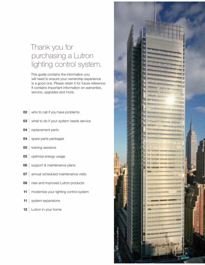
Thank you for purchasing a Lutron lighting control system.This guide contains the information you will need to ensure your ownership experience is a good one. Please retain it for future reference. It contains important information on warranties, service, upgrades and more.
02 | who to call if you have problems
03 | what to do if your system needs service
04 | replacement parts
04 | spare parts packages
05 | training sessions
05 | optimize energy usage
06 | support & maintenance plans
07 | annual scheduled maintenance visits
08 | new and improved Lutron products
11 | modernize your lighting control system
11 | system expansions 12 | Lutron in your home
© P
hoto
by
Bria
n R
ose

who to call if you have problems: 1.800.523.946624-hour Technical Support at No ChargeIf you have questions about the operation of your system, or if you are not sure it is functioning properly, Lutron provides around-the-clock technical support. A knowledgeable support staff is ready to answer questions about the operation, programming, and maintenance of your system. They can also direct you to the technical information on our website that is specific to your Lutron products.
From the U.S., call 1.800.523.9466. International customers can dial 1.610.282.3800 or visit www.lutron.com to get more information on our international offices.
Where to Find Your Lutron Job NumberYou can find this number on the cover of any dimming panel. This number could be formatted in one of several ways. It will typically look like one of the following: 012-#### 014-#########
02 | Lutron
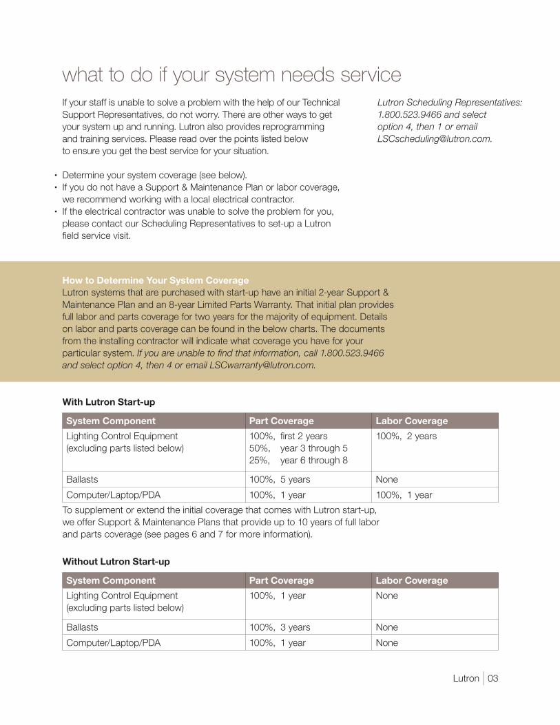
what to do if your system needs service Lutron Scheduling Representatives: 1.800.523.9466 and select option 4, then 1 or email [email protected].
If your staff is unable to solve a problem with the help of our Technical
Support Representatives, do not worry. There are other ways to get
your system up and running. Lutron also provides reprogramming
and training services. Please read over the points listed below
to ensure you get the best service for your situation.
Determine your system coverage (see below).
If you do not have a Support & Maintenance Plan or labor coverage,
we recommend working with a local electrical contractor.
If the electrical contractor was unable to solve the problem for you,
please contact our Scheduling Representatives to set-up a Lutron
field service visit.
How to Determine Your System CoverageLutron systems that are purchased with start-up have an initial 2-year Support &
Maintenance Plan and an 8-year Limited Parts Warranty. That initial plan provides
full labor and parts coverage for two years for the majority of equipment. Details
on labor and parts coverage can be found in the below charts. The documents
from the installing contractor will indicate what coverage you have for your
particular system. If you are unable to find that information, call 1.800.523.9466 and select option 4, then 4 or email [email protected].
With Lutron Start-up
System Component Part Coverage Labor Coverage
Lighting Control Equipment
(excluding parts listed below)
100%, first 2 years
50%, year 3 through 5
25%, year 6 through 8
100%, 2 years
Ballasts 100%, 5 years None
Computer/Laptop/PDA 100%, 1 year 100%, 1 year
To supplement or extend the initial coverage that comes with Lutron start-up,
we offer Support & Maintenance Plans that provide up to 10 years of full labor
and parts coverage (see pages 6 and 7 for more information).
Without Lutron Start-up
System Component Part Coverage Labor Coverage
Lighting Control Equipment
(excluding parts listed below)
100%, 1 year None
Ballasts 100%, 3 years None
Computer/Laptop/PDA 100%, 1 year None
Lutron | 03

replacement partsIf you are experiencing a problem with your system and need to order replacement parts, you can call one of our Parts Specialists. If possible, please have the part number of the failed item as well as the Lutron Job Number for your system. In many cases, we will have the parts in stock and will send them to you in as little as two days.
For custom products and older generation systems, it may take longer for us to provide replacement parts. In those cases, the components that we need to make the products may no longer be available from our suppliers. As a result, we may ask you to send the failed part back to us so we can try to repair it rather than replace it.
To request more information, please call 1.800.523.9466 and select option 4, then 2 or email [email protected].
spare parts packagesHaving a stock of parts at your facility can ensure that small problems will be resolved rapidly. Some components can be installed in minutes, and Lutron’s 24-hour Technical Support Representatives are available to walk your maintenance team or local contractor through the process.
We can prepare a recommended spare parts list based upon the specific configuration of your system and any unique requirements you have.
To request more information, please call 1.800.523.9466 and select option 4, then 2 or email [email protected].
04 | Lutron

training sessionsOn Our Site: The software used with our GRAFIK™ 5000/6000/7000 and Quantum™ systems allows a facility manager to reprogram, control, and monitor the lighting control system. To maximize the benefits this software provides, Lutron offers Facility Manager Training at our headquarters in Coopersburg, PA. The cost of these classes is minimal, and the feedback from past attendees has indicated that the training is well worth the time investment.
Go to www.lutron.com/training to see course dates and registration details.
On Your Site: If staff turnover has left you without anyone who knows how to operate and maintain your system, you can purchase a day of personalized training. This could be an ideal time to make any timeclock or wall control programming changes.
System specific training agendas are available on our website at www.lutron.com/service.
optimize energy usageAlthough your lights turn on and off, there are many features that go beyond those basic options. Lighting strategies that take advantage of those new features can lead to more productive environments, happier occupants, and reduced lighting electricity bills.
Studies show that office buildings expend 44% of electricity on lighting alone. You can reduce your lighting energy consumption with a Lutron System Optimization Visit. This type of visit will help you implement strategies that will result in better system performance and more efficient energy usage.
To request more information, please call 1.800.523.9466 and select option 4, then 5 or email [email protected].
Lutron | 05
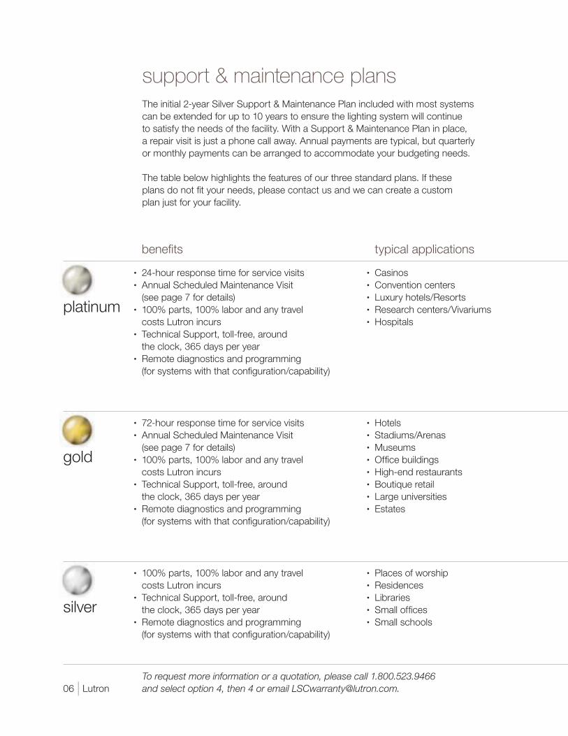
benefits typical applications
platinum
24-hour response time for service visits
Annual Scheduled Maintenance Visit
(see page 7 for details)
100% parts, 100% labor and any travel
costs Lutron incurs
Technical Support, toll-free, around
the clock, 365 days per year
Remote diagnostics and programming
(for systems with that configuration/capability)
Casinos
Convention centers
Luxury hotels/Resorts
Research centers/Vivariums
Hospitals
gold
72-hour response time for service visits
Annual Scheduled Maintenance Visit
(see page 7 for details)
100% parts, 100% labor and any travel
costs Lutron incurs
Technical Support, toll-free, around
the clock, 365 days per year
Remote diagnostics and programming
(for systems with that configuration/capability)
Hotels
Stadiums/Arenas
Museums
Office buildings
High-end restaurants
Boutique retail
Large universities
Estates
silver
100% parts, 100% labor and any travel
costs Lutron incurs
Technical Support, toll-free, around
the clock, 365 days per year
Remote diagnostics and programming
(for systems with that configuration/capability)
Places of worship
Residences
Libraries
Small offices
Small schools
support & maintenance plans The initial 2-year Silver Support & Maintenance Plan included with most systems
can be extended for up to 10 years to ensure the lighting system will continue
to satisfy the needs of the facility. With a Support & Maintenance Plan in place,
a repair visit is just a phone call away. Annual payments are typical, but quarterly
or monthly payments can be arranged to accommodate your budgeting needs.
The table below highlights the features of our three standard plans. If these
plans do not fit your needs, please contact us and we can create a custom
plan just for your facility.
To request more information or a quotation, please call 1.800.523.9466 and select option 4, then 4 or email [email protected]. 06 | Lutron

annual scheduled maintenance visits Our Gold and Platinum Support & Maintenance Plan customers automatically
receive an Annual Scheduled Maintenance Visit, but any customer can purchase
a day of this service. According to each site’s requests and needs, the Lutron
Field Service Engineer may complete the following tasks during this visit:
Train facility staff
Update staff on new features and capabilities
Make minor programming changes
Perform a system check and preventative maintenance
Provide a system status report
Compile a list of spare parts to consider for site
Lutron | 07

new and improved Lutron products Add Engraving to Existing ControlsWith proper labeling of the buttons on existing controls, your lighting system will be easier to use for you and anyone that enters the space. Nearly all Lutron wall controls can be engraved with labels for individual buttons or the entire control. Most engravings are custom to the project but standard options are also available. Engravings are available in a variety of colors and we can laser engrave in any language.
Engraving sheets are available at www.lutron.com/seeTouch.
08 | Lutron

Upgrade to seeTouch®
An engraved control is better than one that is not, but a control with engraving that can be read in the dark is the ultimate solution. Controls in Lutron’s GRAFIK™
3000/4000/5000/6000/7000 lighting control systems can be replaced to feature this intuitive and ergonomic wall control option.
To upgrade your controls, please call 1.800.523.9466 and select option 4, then 5, or email [email protected].
Upgrade to GRAFIK Eye® QSWith the positive feedback from the experience our customers had with seeTouch controls, we updated our GRAFIK Eye product to include some of the same engraving and backlit features. An added bonus to the GRAFIK Eye QS is the opportunity to conveniently control shades and lighting from one control station.
To upgrade your controls, please call 1.800.523.9466 and select option 4, then 5,or email [email protected].
seeTouch®
Discover the intuitive simplicity of Lutron’s seeTouch controls. As you can see above, our wall controls have continued to evolve into more beautiful and user-friendly additions to your facility. Engraved buttons make them easy to use for newcomers to the space and the backlit buttons remove the need to search for wall controls in the dark.
For more information, please visit www.lutron.com/seeTouch.
GRAFIK Eye® QSSet your lights and shades just right for any task or activity in any room of your building. Easily recall these settings with the touch of a button. The new GRAFIK Eye QS provides convenient control and enhancement of the visual environment for the people inside the space.
For more information, please visit www.lutron.com/GRAFIKEyeQS.
Lutron | 09

10 | Lutron

system expansionsIf you are expanding your building, or if existing areas of the building need to be incorporated into the system, we can provide a solution. Our systems are modular and expandable, allowing you to add capabilities or capacity as required.
Adding photo or occupancy sensors can help save energy. Using Lutron occupancy sensors can eliminate 20 – 30% of lighting energy costs.
Our Replacement Systems Specialists can review the equipment you have, work with you to determine what capabilities and features you want, and propose comprehensive solutions for your lighting needs.
For more information, please call 1.800.523.9466 and select option 4, then 5 or email [email protected].
modernize your lighting control systemYou originally purchased a Lutron lighting control system because you wanted the ultimate in reliability and performance. The pace of innovation in Lutron’s products has been rapid – the systems of today have features that were beyond reach just five years ago. These features may be just what you are looking for as you modernize your facilities.
In addition to improved serviceability, a new system brings advanced control features and energy saving capabilities that will take your lighting control experience to the next level.
Regardless of your reasons for wanting to upgrade or replace your system, Lutron will integrate the best products and services to give you a solution that meets your needs.
For more information on upgrading your system, please call 1.800.523.9466 and select option 4, then 5 or email [email protected].
Lutron | 11

Lutron in your homeWhen it comes to controlling electric and natural light, Lutron has the best products for any application, including your home.
The same world-class quality and engineering in the lighting controls in Buckingham Palace and the White House can be found in the dimmer that you can purchase for your home. After all, we feel that everyone deserves the benefits of dimming such as increased bulb life, improved energy savings, and enhanced room settings.
For assistance in locating Lutron products for your home, go to www.lutron.com.
www.lutron.com
Save energy beautifully
dimming the lights about
saves electricity
extends bulb life*
10% 10% 2 times longer
25% 20% 4 times longer
50% 40% 20 times longer
75% 60% 20 times longer +
* incandescent and halogen
12 | Lutron

www.lutron.com/service
Lutron Services Co., Inc.7200 Suter RoadCoopersburg, PA 18036-1299
World Headquarters 1.610.282.3800Technical Support Center 1.800.523.9466
© 02/2009 Lutron Services Co., Inc. I P/N 367-341 Rev. C Made and printed in the U.S.A.
System Solutions Lighting Control System O & M Manual
Job Name: Toll-Free 24/7 Technical Support Line: 1.800.523.9466
Job Number: Field Service Scheduling 1.800.523.9466 ext.4439
Install & Setup Guides

LUT
RO
NSys
tem
Inst
alla
tion
and
Op
erat
ion
Gui
de
R
Chi
nese
Esp
año
lFr
ança
is
Ple
ase
Rea
d
Co
nten
tsIn
stal
latio
nFe
atur
es a
nd F
unct
ions
of
the
GR
AFI
KE
yeQ
S S
yste
m .
2W
iring
the
GR
AFI
KE
yeQ
S S
yste
m .
. . .
. . .
. . .
. . .
. . .
.3
Wiri
ng t
he G
RA
FIK
Eye
QS
Sys
tem
P
ELV
(Cla
ss 2
:US
A) C
able
. . .
. . .
. . .
. . .
. . .
. . .
. .
4Q
SS
yste
m L
ow-V
olta
ge C
ontr
ol W
iring
. . .
. . .
. . .
. . .
. .5
QS
Sys
tem
Low
-Vol
tage
Ter
min
al C
onne
ctio
ns .
. . .
. . .
6In
stal
ling
the
GR
AFI
KE
yeQ
S S
yste
m .
. . .
. . .
. . .
. . .
. .7
Zon
e S
etup
. .
. . .
. . .
. . .
. . .
. . .
. . .
. . .
. . .
. . .
. . .
. . .
.8
Op
erat
ion
Pre
pro
gram
med
But
ton
Func
tiona
lity
. . .
. . .
. . .
. . .
. .
10G
ener
al F
unct
iona
lity
. . .
. . .
. . .
. . .
. . .
. . .
. . .
. . .
. . .
11G
ener
al F
unct
iona
lity:
Pro
gram
min
g M
ode
. . .
. . .
. . .
.12
Zon
e B
utto
n O
per
atio
n .
. . .
. . .
. . .
. . .
. . .
. . .
. . .
. . .
.13
Qui
ck S
cene
Pro
gram
min
g .
. . .
. . .
. . .
. . .
. . .
. . .
. . .
15S
cene
Set
up .
. . .
. . .
. . .
. . .
. . .
. . .
. . .
. . .
. . .
. . .
. . .1
6LE
DD
isp
lays
for
Lig
htin
g Le
vels
. . .
. . .
. . .
. . .
. . .
. . .
18A
dju
stin
g W
ind
ow T
reat
men
t S
ettin
gs .
. . .
. . .
. . .
. . .
.19
Tim
eclo
ck O
per
atio
n .
. . .
. . .
. . .
. . .
. . .
. . .
. . .
. . .
. . .2
3S
et S
ave
Mod
e .
. . .
. . .
. . .
. . .
. . .
. . .
. . .
. . .
. . .
. . .
.28
Set
Up
Occ
upan
t S
enso
r .
. . .
. . .
. . .
. . .
. . .
. . .
. . .
. .29
Act
ivat
e S
yste
m A
cces
sorie
s .
. . .
. . .
. . .
. . .
. . .
. . .
. .30
Face
pla
te R
emov
al .
. . .
. . .
. . .
. . .
. . .
. . .
. . .
. . .
. . .
.30
Trou
ble
shoo
ting
. . .
. . .
. . .
. . .
. . .
. . .
. . .
. . .
. . .
. . .
. .3
1
Men
u O
ptio
ns .
. . .
. . .
. . .
. . .
. . .
. . .
. . .
. . .
. . .
. . .
. .34
War
rant
y .
. . .
. . .
. . .
. . .
. . .
. . .
. . .
. . .
. . .
. . .
. . .
. . .3
5C
onta
ct In
form
atio
n .
. . .
. . .
. . .
. . .
. . .
. . .
. . .
. . .
. . .3
6
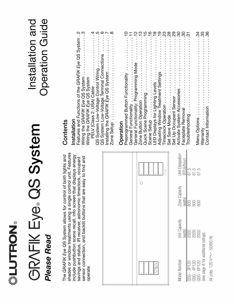
The
GR
AFI
KE
yeQ
S S
yste
m a
llow
s fo
r co
ntro
l of
bot
h lig
hts
and
shad
es o
r w
ind
ow t
reat
men
ts u
sing
a s
ingl
e co
ntro
l uni
t. F
eatu
res
incl
ude
pus
hbut
ton
scen
e re
call,
info
scr
een
that
dis
pla
ys e
nerg
ysa
ving
s an
d s
tatu
s, IR
rece
iver
, as
tron
omic
tim
eclo
ck,
occu
pan
tse
nsor
con
nect
ion,
and
bac
klit
but
tons
tha
t ar
e ea
sy t
o fin
d a
ndop
erat
e.
Mod
el N
umbe
rUn
it Ca
pacit
yZo
ne C
apac
ityUn
it Di
ssip
atio
n(w
atts
)(w
atts
)(B
TUs/
hour
)QS
G -
3P12
020
0080
061
.5QS
G -
4P12
020
0080
061
.5QS
G -
6P12
020
0080
061
.5(s
ee p
age
8 fo
r add
itiona
l rat
ings
)
All u
nits
:120
V50
/60
Hz

RG
RA
FIK
Eye
®Q
SS
yste
m In
stal
latio
n an
d O
per
atio
n G
uid
e
2
OK
1
2
3
4
5
6In
fo s
cree
nD
isp
lays
sta
tus;
Lig
htin
g c
olu
mn
Sce
ne b
utto
ns w
ith in
tegr
alS
had
e co
lum
nP
rese
t an
d r
aise
/low
erb
utto
ns w
ith in
tegr
al L
ED
s(m
axim
um o
f 3
colu
mns
)
Sp
ace
for
futu
re
shad
e co
lum
ns
Zo
ne n
umb
ers
Zo
ne r
aise
/lo
wer
but
tons
Zon
e LE
Ds
dis
pla
y cu
rren
t
Tim
eclo
ck s
tatu
s b
utto
nD
isp
lays
cur
rent
OK
but
ton
Use
d f
or p
rogr
amm
ing
Infr
ared
rec
eive
rFo
r ha
ndhe
ld r
emot
eus
e
Mas
ter
but
tons
Tem
por
arily
rai
se a
nd lo
wer
US
Bty
pe
min
i B in
put
{Hin
ged
fac
epla
te
Hin
ged
fac
epla
te
Fea
ture
s an
d F
unct
ions
of
the
GR
AF
IKE
ye®
QS
Sys
tem
RG
RA
FIK
Eye
®Q
SS
yste
m In
stal
latio
n an
d O
per
atio
n G
uid
e
3
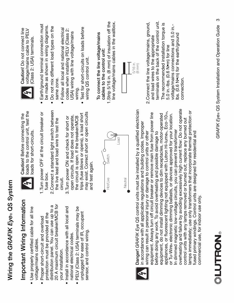
Wiri
ng t
he G
RA
FIK
Eye
®Q
S S
yste
m
Imp
ort
ant
Wiri
ng In
form
atio
n•
Use
pro
per
ly c
ertif
ied
cab
le f
or a
ll lin
evo
ltage
/mai
ns c
able
s.•
Pro
per
sho
rt-c
ircui
t an
d o
verlo
adp
rote
ctio
n m
ust
be
pro
vid
ed a
t th
ed
istr
ibut
ion
pan
el.
You
can
use
up t
o a
20A
max
imum
circ
uit
bre
aker
/MC
B f
oryo
ur in
stal
latio
n.•
Inst
all i
n ac
cord
ance
with
all
loca
l and
natio
nal e
lect
rical
cod
es.
•P
ELV
(Cla
ss 2
:US
A)t
erm
inal
s m
ay b
eun
plu
gged
for
eas
e of
IR,
occu
pan
tse
nsor
, an
d c
ontr
ol w
iring
.
Cau
tion!
Bef
ore
conn
ectin
g th
elo
ads
to t
he c
ontr
ol u
nit,
tes
t th
elo
ads
for
shor
t-ci
rcui
ts.
1.Tu
rn p
ower
OFF
at
the
circ
uit
bre
aker
or
fuse
box
.2.
Con
nect
a s
tand
ard
ligh
t sw
itch
bet
wee
nth
e liv
e le
ad a
nd lo
ad w
ire t
o te
st t
heci
rcui
t.3.
Turn
pow
er O
N a
nd c
heck
for
sho
rt o
rop
en c
ircui
ts.
If lo
ad d
oes
not
oper
ate,
the
circ
uit
is o
pen
. If
the
bre
aker
/MC
Btr
ips
(fuse
blo
ws
or o
pen
s),
a lo
ad s
hort
may
exi
st.
Cor
rect
sho
rt o
r op
en c
ircui
tsan
d t
est
agai
n.
Cau
tion!
Do
not
conn
ect
line
volta
ge/m
ains
cab
le t
o P
ELV
(Cla
ss 2
:US
A) t
erm
inal
s.
•E
arth
/gro
und
ter
min
al c
onne
ctio
n m
ust
be
mad
e as
sho
wn
in w
iring
dia
gram
s.•
Do
not
mix
diff
eren
t lo
ad t
ypes
on
the
sam
e zo
ne.
•Fo
llow
all
loca
l and
nat
iona
l ele
ctric
alco
des
whe
n in
stal
ling
PE
LV (C
lass
2:
US
A) w
iring
with
line
vol
tage
/mai
nsw
iring
.•
Test
for
sho
rt-c
ircui
ts o
n lo
ads
bef
ore
wiri
ng Q
S c
ontr
ol u
nit.
To c
onn
ect
the
line
volta
ge/
mai
nsca
ble
s to
the
co
ntro
l uni
t:1.
Str
ip 5
/16
in.
(8 m
m) o
f in
sula
tion
off
the
line
volta
ge/m
ains
cab
les
in t
he w
allb
ox.
2.C
onne
ct t
he li
ne v
olta
ge/m
ains
, gr
ound
,an
d lo
ad w
ires
to t
he a
pp
rop
riate
term
inal
s on
the
bac
k of
the
con
trol
uni
t.Th
e re
com
men
ded
inst
alla
tion
torq
ue is
5.0
in.-
lbs.
(0.6
N•m
) for
line
volta
ge/m
ains
con
nect
ions
and
5.0
in.-
lbs.
(0.6
N•m
) for
the
ear
th/g
roun
dco
nnec
tion.3/
8 in
. (10
mm
)5/
16 in
. (8
mm
)D
ang
er!G
RA
FIK
Eye
QS
con
trol
uni
ts m
ust
be
inst
alle
d b
y a
qua
lifie
d e
lect
ricia
nin
acc
ord
ance
with
all
app
licab
le r
egul
atio
ns a
nd b
uild
ing
cod
es. I
mp
rop
erw
iring
can
res
ult
in p
erso
nal i
njur
y or
dam
age
to c
ontr
ol u
nits
or
othe
req
uip
men
t. A
lway
s tu
rn o
ff ci
rcui
t b
reak
er o
r re
mov
e m
ain
fuse
from
pow
er li
neb
efor
e d
oing
any
wor
k. T
o av
oid
ove
rhea
ting
and
pos
sib
le d
amag
e to
equi
pm
ent,
do
not
inst
all d
imm
ing
dev
ices
to
dim
rec
epta
cles
, mot
or-o
per
ated
app
lianc
es, o
r flu
ores
cent
ligh
ting
not
equi
pp
ed w
ith L
utro
n H
i-lu
me ®
, Eco
-10T
M,
or T
u-W
ire®
elec
tron
ic d
imm
ing
bal
last
s, o
r d
evic
es a
pp
rove
d fo
r yo
ur lo
catio
n.In
dim
med
mag
netic
low
-vol
tage
circ
uits
, you
can
pre
vent
tra
nsfo
rmer
over
heat
ing
and
failu
re b
y av
oid
ing
exce
ssiv
ely
high
cur
rent
flow
: Do
not
oper
ate
cont
rol u
nits
with
any
lam
ps
rem
oved
or
bur
ned
out
; rep
lace
any
bur
ned
out
lam
ps
imm
edia
tely
; use
onl
y tr
ansf
orm
ers
that
inco
rpor
ate
ther
mal
pro
tect
ion
orfu
sed
prim
ary
win
din
gs. C
ontr
ol u
nits
are
des
igne
d fo
r re
sid
entia
l and
com
mer
cial
use
, for
ind
oor
use
only
.
Neu
tral
Hot
/Liv
eS
witc
h
Load

Occ
upan
t S
enso
r W
iring
RG
RA
FIK
Eye
®Q
SS
yste
m In
stal
latio
n an
d O
per
atio
n G
uid
e
4
1 2 3 4
1:CO
M2:
24 V
3:M
UX4:
MUX
1 2A B C
Not
e:U
se a
ppro
pria
te w
ire c
onne
ctin
g de
vice
s as
spec
ified
by
loca
l cod
es.
Occ
upan
tse
nsor
12
34
56
LN
Dis
trib
utio
n P
anel
LN
To L
oad
1
To L
oad
2
To L
oad
3
To L
oad
4
To L
oad
5
To L
oad
6
Co
ntro
l Wiri
ng
Wiri
ng t
he G
RA
FIK
Eye
®Q
S S
yste
mP
ELV
(Cla
ss 2
:US
A)C
able
IR W
iring
From
ext
erna
lIR
con
nect
ion
(by
othe
rs)
Co
mm
on
and
po
wer
(ter
min
als
1 an
d 2
): Tw
o #1
8 A
WG
(1.0
mm
2 ) ea
ch t
erm
inal
#18
AW
G(1
.0 m
m2 )
each
ter
min
al
#12
AW
G(2
.5 m
m2 )
each
ter
min
al
1 2 3 41 2 A B C
12
34
56
LN
#18
AW
G(1
.0 m
m2 )
each
ter
min
al
120
V
1:IR
DAT
A2:
IR C
OM
A:OC
C SI
GB:
24 V
C:OC
C CO
M
To c
ontro
l sta
tions
,w
indo
w tr
eatm
ents
, or
othe
r G
RA
FIK
Eye
QS
cont
rol u
nits
Line
Vo
ltag
e/M
ains
Cab
les
and
Lo
ad W
iring
Dat
a (t
erm
inal
s 3
and
4):
Twis
ted
, sh
ield
ed p
air
#22
AW
G(1
.0 m
m2 )
each
ter
min
al

RG
RA
FIK
Eye
®Q
SS
yste
m In
stal
latio
n an
d O
per
atio
n G
uid
e
5
•S
yste
m c
omm
unic
atio
n us
es P
ELV
(Cla
ss2:
US
A) l
ow-v
olta
ge w
iring
.•
Follo
w a
ll lo
cal a
nd n
atio
nal e
lect
rical
cod
es w
hen
inst
allin
g P
ELV
(Cla
ss 2
:U
SA
) wiri
ng w
ith li
ne v
olta
ge/m
ains
wiri
ng.
•E
ach
term
inal
acc
epts
up
to
two
#18
AW
G(1
.0 m
m2 )
wire
s.•
Tota
l len
gth
of c
ontr
ol li
nk m
ust
not
exce
ed 2
,000
ft.
(610
m).
•M
ake
all c
onne
ctio
ns in
the
con
trol
uni
t’sw
allb
ox.
•A
QS
syst
em c
an h
ave
up t
o 10
0 zo
nes
and
100
dev
ices
(see
tab
le b
elow
).•
Wiri
ng c
an b
e T-
tap
ped
or
dai
sy-c
hain
ed.
•W
ire s
izes
:-
Two
#18
AW
G(1
.0 m
m2 )
cond
ucto
rs f
orco
ntro
l pow
er.
- O
ne t
wis
ted
, sh
ield
ed p
air
of #
22 A
WG
(1.0
mm
2 ) fo
r d
ata
link.
- C
able
is a
vaila
ble
fro
m L
utro
n:G
RX
-CB
L-S
-500
(non
-ple
num
)G
RX
-CB
LP-S
-500
(ple
num
rat
ed).
Che
ck c
omp
atib
ility
in y
our
area
.LU
TR
ON
LU
TR
ON
LUT
RO
N
LU
TR
ON
LU
TR
ON
LUT
RO
N
LU
TR
ON
GR
AFI
KEy
eQ
SS
ivoi
aQ
Sse
eTou
chQ
S
LUT
RO
N
LU
TR
ON
LUT
RO
N
LU
TR
ON
LU
TR
ON
LU
TR
ON
LUT
RO
N
Dai
sy-C
hain
Wiri
ng E
xam
ple
T-Ta
p W
iring
Exa
mp
le
GR
AFI
KEy
eQ
S
Siv
oia
QS
QS
sm
art
pow
ersu
pply
pan
el
QS
sm
art p
ower
supp
ly p
anel
seeT
ouch
QS
QS
Sys
tem
Lo
w-V
olta
ge
Co
ntro
l Wiri
ng
Sys
tem
Lim
itsQ
SD
evic
eZ
one
Cou
ntD
evic
e C
ount
3-zo
ne Q
S3
1
4-zo
ne Q
S4
1
6-zo
ne Q
S6
1
seeT
ouch
QS0
1
Sivo
iaQS
1
1
QS s
mar
t pow
er s
uppl
y pa
nel
01
LUT
RO
N
LUT
RO
N
LUT
RO
N
LU
TR
ON
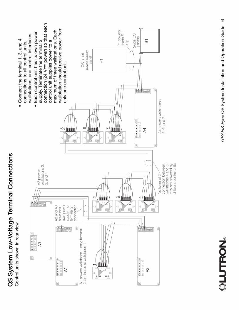
QS
Sys
tem
Lo
w-V
olta
ge
Term
inal
Co
nnec
tions
RG
RA
FIK
Eye
®Q
SS
yste
m In
stal
latio
n an
d O
per
atio
n G
uid
e
6
4 3 2 1 4 3 2 1 4 3 2 1
4 3 2 1 4 3 2 14 3 2 1
4 3 2 1
123412ABC
12
34
56
HN
123412ABC
12
34
56
HN
123412ABC
12
34
56
HN
123412ABC
12
34
56
HN
A1
2 3 4
1
A2
A3
A1
pow
ers
wal
lsta
tion
1 on
ly;
term
inal
2 te
rmin
ates
at w
alls
tatio
n 1
A2
and
A3
have
thei
row
n po
wer
supp
ly;
note
rmin
al 2
conn
ectio
n
A3
pow
ers
wal
lsta
tions
2,
3, a
nd 4
A4
P1
S1
A4
pow
ers
wal
lsta
tions
5, 6
, an
d 7
P1
pow
ers
shad
e S
1on
ly
Siv
oia
QS
shad
e
QS
sm
art
pow
er s
uppl
ypa
nel
Con
trol
uni
ts s
how
n in
rea
r vi
ew
5 6 7
•C
onne
ct t
he t
erm
inal
1,
3, a
nd 4
conn
ectio
ns t
o al
l con
trol
uni
ts,
wal
lsta
tions
, an
d c
ontr
ol in
terf
aces
.•
Eac
h co
ntro
l uni
t ha
s its
ow
n p
ower
sup
ply
. Te
rmin
ate
the
term
inal
2co
nnec
tion
(24
Vp
ower
) so
that
eac
hco
ntro
l uni
t su
pp
lies
pow
er t
o a
max
imum
of
thre
e w
alls
tatio
ns.
Eac
hw
alls
tatio
n sh
ould
rec
eive
pow
er f
rom
only
one
con
trol
uni
t.
No
term
inal
2co
nnec
tion
betw
een
wal
lsta
tions
4 a
nd 5
;th
ey a
re p
ower
ed b
ydi
ffere
nt c
ontro
l uni
ts

RG
RA
FIK
Eye
®Q
SS
yste
m In
stal
latio
n an
d O
per
atio
n G
uid
e
7
Inst
allin
g t
he G
RA
FIK
Eye
®Q
S S
yste
m1.
Mou
nt a
3 1
/2-i
n. (8
9 m
m) d
eep
4-
gang
U.S
. w
allb
ox o
n a
dry
, fla
tin
doo
r su
rfac
e th
at is
acc
essi
ble
and
allo
ws
for
syst
em p
rogr
amm
ing
and
oper
atio
n. A
llow
at
leas
t 4
1/2
in.
(110
mm
) cle
aran
ce a
bov
e an
d b
elow
the
face
pla
te t
o en
sure
pro
per
hea
td
issi
pat
ion.
Allo
w 1
in.
(25
mm
) for
face
pla
te o
verh
ang
on a
ll si
des
. N
ote
:4-g
ang
wal
lbox
ava
ilab
le f
rom
Lutr
on;
P/N
241
400.
2.M
ount
the
con
trol
uni
t in
the
wal
lbox
as s
how
n us
ing
the
four
scr
ews
pro
-vi
ded
.N
ote
:Fol
low
all
loca
l and
nat
iona
lel
ectr
ical
cod
es w
hen
inst
allin
g P
ELV
(Cla
ss 2
: U
SA
) wiri
ng w
ith li
nevo
ltage
/mai
ns w
iring
.
3.A
pp
ly t
he p
rote
ctiv
e ov
erla
y to
the
cont
rol u
nit.
See
pag
e 14
for
inst
ruct
ions
for
nam
ing
zone
s.
Test
the
Wiri
ng1.
Res
tore
pow
er.
2.P
ress
the
top
but
ton
on t
he li
ghtin
gke
ypad
. Th
e LE
D w
ill li
ght.
3.P
ress
the
zon
e ra
ise
or lo
wer
but
ton.
Mak
e su
re t
he c
ontr
ol u
nit
is d
imm
ing
all
conn
ecte
d lo
ads.
Pro
tect
ive
over
lay
(app
ly a
fter
inst
alla
tion)
Not
e: W
hen
tight
enin
g m
ount
ing
scre
ws,
mak
e su
re th
at th
e hi
nged
cove
r an
d fa
cepl
ate
will
open
fully
,as
sho
wn.
Wal
l
7.9
in.
(200
mm
)
3.5
in.
(87
mm
)3.
75 in
.(9
5 m
m)
LUT
RO
N
LUT
RO
N
Face
plat
e ov
erha
ngs
wal
lbox
on
all s
ides
; al
low
1 in
. (2
5 m
m)
4.5
in.
(110
mm
)

Zo
ne S
etup
Ass
ign
Load
Typ
e1.
Ent
er p
rogr
amm
ing
mod
e (s
ee p
age
12).
2.U
se t
he m
aste
r b
utto
ns t
o hi
ghlig
ht “
Zon
ese
tup
” an
d p
ress
the
OK
but
ton
toac
cep
t.3.
Use
the
mas
ter
but
tons
to
high
light
“Lo
adty
pe”
. P
ress
the
OK
but
ton
to a
ccep
t.4.
Use
the
zon
e ra
ise/
low
er b
utto
ns t
och
oose
the
load
typ
e fo
r th
at z
one.
See
the
list
bel
ow f
or s
upp
orte
d lo
ad t
ypes
.P
ress
the
OK
but
ton
to a
ccep
t.5.
The
info
scr
een
will
dis
pla
y a
conf
irmat
ion
scre
en t
hat
your
load
typ
eha
s b
een
save
d.
6.E
xit
pro
gram
min
g m
ode
(see
pag
e 12
).
RG
RA
FIK
Eye
®Q
SS
yste
m In
stal
latio
n an
d O
per
atio
n G
uid
e
8
Mai
n m
enu
Occ
sen
sor
Zon
e se
tup
Zo
ne s
etup
Hig
h en
d
Load
typ
e
Set
typ
e us
ing
zone
con
trol
s
Load
typ
e
OK
1
2
3
4
5
6U
se th
ezo
nera
ise/
low
erbu
ttons
toch
oose
the
load
type
for
that
zon
e.
Mas
ter
butto
ns
OK
bu
tton
Load
Typ
e N
ote
s•
All
elec
tron
ic lo
w-v
olta
ge (E
LV)l
ight
ing
used
with
an
inte
rfac
e m
ust
be
rate
d f
orre
vers
e p
hase
con
trol
dim
min
g. B
efor
ein
stal
ling
an E
LVlig
ht s
ourc
e, v
erify
with
the
man
ufac
ture
r th
at t
heir
tran
sfor
mer
can
be
dim
med
. W
hen
dim
min
g, a
n E
LVin
terf
ace
mus
t b
e us
ed w
ith t
he c
ontr
olun
it.•
Not
all
zone
s m
ust
be
conn
ecte
d;
how
ever
, co
nnec
ted
zon
es m
ust
have
am
inim
um lo
ad o
f 25
W.
•N
o zo
ne m
ay b
e lo
aded
with
mor
e th
an80
0 W
.•
Max
imum
tot
al li
ghtin
g lo
ad p
er u
nit
is
16 A
.•
Max
imum
tot
al li
ghtin
g lo
ad f
or a
mag
netic
low
-vol
tage
(MLV
)loa
d is
200
0VA
or
1600
wat
ts a
fter
tra
nsfo
rmer
.M
axim
um lo
ad p
er M
LV z
one
is 8
00 V
A o
r60
0 w
atts
.
Set
ting
Lo
ad T
ypes
Fixt
ure
load
typ
e
Inca
ndes
cent
MLV
(mag
netic
low
-vol
tage
)EL
V(e
lect
roni
c lo
w-v
olta
ge)
Hi-L
ume/
Eco-
10No
n-di
mNe
on/C
old
cath
ode
Tu-W
ire
Dire
ct c
ontr
ol v
ia
GR
AFI
KE
yeQ
S
Inca
ndes
cent
MLV
-- -- Non-
dim
LOF
Oor
Non
-dim
FOF
ONe
on,C
CTu
-Wire
Con
trol
via
p
ower
mod
ule
Pow
er m
odul
ePo
wer
mod
ule
Pow
er m
odul
eFl
uore
scen
t mod
ule
Non-
dim
LOF
Oor
Non
-dim
FOF
ONe
on,C
CTu
-Wire
LUT
RO
NLU
TR
ON
Cho
ose
this
load
typ
e fr
om t
he m
enu
on t
he G
RA
FIK
Eye
QS
:
Sav
ed Sav
ed

Set
Min
imum
Lev
el (o
ptio
nal)
Som
e lo
cal r
egul
atio
ns s
pec
ify a
min
imum
ligh
ting
leve
l for
dim
min
gzo
nes
in o
ccup
ied
bui
ldin
gs.
If th
isp
erta
ins
to y
ou,
follo
w t
hese
ste
ps
tose
t up
you
r m
inim
um li
ghtin
g le
vel.
1. E
nter
pro
gram
min
g m
ode
(see
pag
e 12
)an
d s
elec
t “Z
one
setu
p,”
the
n “M
inle
vel”
. P
ress
the
OK
but
ton
to a
ccep
t.2.
Use
the
mas
ter
but
tons
to
high
light
“OFF
” if
you
wan
t yo
ur li
ghts
to
go a
llth
e w
ay o
ff at
the
ir m
inim
um li
ght
leve
l,or
“10
%”
if yo
u w
ant
that
to
be
the
min
imum
ligh
t le
vel.
Pre
ss t
he O
Kb
utto
nto
acc
ept.
No
te:N
on-d
im lo
ads
will
turn
off
rega
rdle
ss o
f th
e m
inim
um le
vel s
ettin
g.3.
The
info
scr
een
will
dis
pla
y a
conf
irmat
ion
scre
en t
hat
your
min
imum
leve
l has
bee
n sa
ved
.4.
Exi
t p
rogr
amm
ing
mod
e (s
ee p
age
12).
RG
RA
FIK
Eye
®Q
SS
yste
m In
stal
latio
n an
d O
per
atio
n G
uid
e
9
Zo
ne S
etup
Set
Hig
h E
nd o
r Lo
w E
nd Hig
h an
d lo
w e
nd t
rim s
ettin
gs li
mit
the
max
imum
and
min
imum
out
put
of
ad
imm
ing
zone
. Tr
im le
vels
are
set
auto
mat
ical
ly w
hen
the
load
typ
e is
pro
gram
med
. C
hang
e th
e hi
gh o
r lo
wen
d t
rim f
or a
zon
e on
ly if
the
def
ault
sett
ing
need
s to
be
adju
sted
.1.
Ent
er p
rogr
amm
ing
mod
e (s
ee p
age
12).
2.U
se t
he m
aste
r b
utto
ns t
o hi
ghlig
ht “
Zon
ese
tup
” an
d p
ress
the
OK
but
ton
toac
cep
t.3.
Use
the
mas
ter
but
tons
to
high
light
“H
igh
end
” or
“Lo
w e
nd”
(this
exa
mp
le s
how
slo
w e
nd).
Pre
ss t
he O
Kb
utto
n to
acc
ept.
4. U
se t
he z
one
rais
e/lo
wer
but
tons
to
set
the
high
end
or
low
end
trim
for
tha
tzo
ne.
The
info
scr
een
will
dis
pla
y ea
ch z
one
num
ber
and
per
cent
age
as y
ou a
dju
st it
.P
ress
the
OK
but
ton
to a
ccep
t.5.
The
info
scr
een
will
dis
pla
y a
conf
irmat
ion
scre
en t
hat
your
set
ting
has
bee
n sa
ved
.6.
Exi
t p
rogr
amm
ing
mod
e (s
ee p
age
12).
Mai
n m
enu
Occ
sen
sor
Zon
e se
tup
Zo
ne s
etup
Hig
h en
d
Low
end
Set
trim
usi
ngzo
ne c
ontr
ols
Zo
ne 2
Low
end
OK
1
2
3
4
5
6U
se th
ezo
nera
ise/
low
erbu
ttons
tose
t the
hig
hen
d or
low
end
trim
for
that
zon
e.
Mas
ter
butto
ns
OK
bu
tton
10%
Min
leve
l
OFF
Zo
ne s
etup
Low
end
Min
leve
l
Sav
ed Sav
ed
Sav
ed Sav
ed

Pre
pro
gra
mm
ed B
utto
n F
unct
iona
lity
RG
RA
FIK
Eye
®Q
SS
yste
m In
stal
latio
n an
d O
per
atio
n G
uid
e
10
Lig
htin
g C
olu
mn
But
ton
Pre
pro
gra
mm
ing
(F
acto
ry D
efau
lt:D
imm
able
Lo
ads)
Sce
ne 1
:All
light
s to
100
%S
cene
2:A
ll lig
hts
to 7
5%S
cene
3:A
ll lig
hts
to 5
0%S
cene
4:A
ll lig
hts
to 2
5%
Lig
htin
g C
olu
mn
But
ton
Pre
pro
gra
mm
ing
(F
acto
ry D
efau
lt:N
on-
Dim
Lo
ads)
Sce
ne 1
:All
light
s O
nS
cene
2:A
ll lig
hts
On
Sce
ne 3
:All
light
s O
nS
cene
4:A
ll lig
hts
On
Sha
de
Co
lum
n B
utto
n P
rep
rog
ram
min
g
(Fac
tory
Def
ault:
Siv
oia
QS
sha
des
)A
ll sh
ades
ful
ly o
pen
All
shad
es t
o 50
%A
ll sh
ades
ful
ly c
lose
dLo
wer
/Rai
se a
ll sh
ades
The
GR
AFI
KE
yeQ
S S
yste
m c
ontr
ols
light
s w
ithou
t sp
ecia
l pro
gram
min
g. T
he f
acto
ryd
efau
lts f
or t
he li
ghtin
g co
lum
n b
utto
ns a
re s
how
n b
elow
for
bot
h d
imm
able
and
non
-d
im z
ones
. S
ee p
ages
15
thro
ugh
17 f
or m
etho
ds
for
chan
ging
sce
ne s
ettin
gs.

The
info
scr
een
goes
bla
nk a
fter
20
seco
nds
if th
ere
is n
o b
utto
n p
ress
or
fad
ing.
The
mas
ter
but
tons
als
o ac
tivat
e th
e in
fosc
reen
. Th
ese
but
tons
tem
por
arily
rai
se o
rlo
wer
all
dim
mab
le li
ghts
(exc
ept
thos
ep
rogr
amm
ed a
s un
affe
cted
in t
he c
urre
ntsc
ene)
. A
dju
stm
ents
are
tem
por
ary
and
do
not
affe
ct s
cene
pro
gram
min
g.Th
e O
Kb
utto
n ac
tivat
es t
he in
fo s
cree
n,w
hich
the
n sh
ows
the
curr
ent
scen
e an
d it
sfa
de
time.
The
timec
lock
but
ton
activ
ates
the
info
scre
en a
nd d
isp
lays
the
cur
rent
tim
e, t
hene
xt e
vent
sch
edul
ed t
o oc
cur,
and
wha
tth
at n
ext
even
t is
. P
ress
ing
a se
cond
tim
ed
isp
lays
the
loca
tion
and
the
sunr
ise/
suns
et t
imes
.
RG
RA
FIK
Eye
®Q
SS
yste
m In
stal
latio
n an
d O
per
atio
n G
uid
e
11
OK
Info
scr
een:
see
exa
mp
le s
cree
ns b
elow
Tim
eclo
ck b
utto
n d
isp
lays
the
cur
rent
time
and
the
nex
t sc
hed
uled
eve
nt.
Pre
ssin
g w
hen
in P
rogr
am m
ode
func
tions
as
a“b
ack”
but
ton.
OK
but
ton
activ
ates
the
info
scr
een,
w
hich
sho
ws
the
curr
ent
scen
e’s
fad
etim
e. In
Sav
e A
lway
s m
ode,
allo
ws
fad
etim
e ad
just
men
t. In
Sav
e b
y O
Km
ode,
pre
ssin
ga
seco
nd t
ime
allo
ws
zone
adju
stm
ent;
pre
ssin
g a
third
time
allo
ws
fad
ead
just
men
t.
Mas
ter
but
tons
tem
po
raril
yra
ise
or lo
wer
all l
ight
s (e
xcep
t un
affe
cted
, sh
ades
, an
dno
n-d
im z
ones
) on
this
GR
AFI
KE
yeQ
Sun
it
Sce
ne 1
Mas
ter
rais
e M
aste
r lo
wer
Gen
eral
Fun
ctio
nalit
y
OK
Sce
ne: 1
Ad
just
fad
e03
s
econ
ds
11:2
3 A
M F
ri
Nex
t:5:
00 P
MS
cene
1
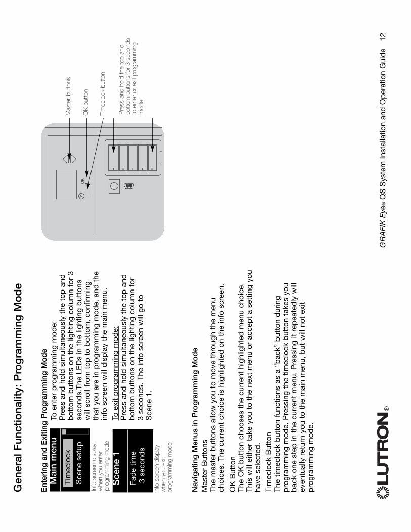
Ent
erin
g a
nd E
xitin
g P
rog
ram
min
g M
od
eT o
ent
er p
rogr
amm
ing
mod
e:P
ress
and
hol
d s
imul
tane
ousl
y th
e to
p a
ndb
otto
m b
utto
ns o
n th
e lig
htin
g co
lum
n fo
r 3
seco
nds.
The
LED
s in
the
ligh
ting
but
tons
will
scr
oll f
rom
top
to
bot
tom
, co
nfirm
ing
that
you
are
in p
rogr
amm
ing
mod
e, a
nd t
hein
fo s
cree
n w
ill d
isp
lay
the
mai
n m
enu.
T o e
xit
pro
gram
min
g m
ode:
Pre
ss a
nd h
old
sim
ulta
neou
sly
the
top
and
bot
tom
but
tons
on
the
light
ing
colu
mn
for
3 se
cond
s. T
he in
fo s
cree
n w
ill g
o to
S
cene
1.
Nav
igat
ing
Men
us in
Pro
gra
mm
ing
Mo
de
Mas
ter
But
tons
The
mas
ter
but
tons
allo
w y
ou t
o m
ove
thro
ugh
the
men
uch
oice
s. T
he c
urre
nt c
hoic
e is
hig
hlig
hted
on
the
info
scr
een.
OK
But
ton
The
OK
but
ton
choo
ses
the
curr
ent
high
light
ed m
enu
choi
ce.
This
will
eith
er t
ake
you
to t
he n
ext
men
u or
acc
ept
a se
ttin
g yo
uha
ve s
elec
ted
.
Tim
eclo
ck B
utto
nTh
e tim
eclo
ck b
utto
n fu
nctio
ns a
s a
“bac
k” b
utto
n d
urin
gp
rogr
amm
ing
mod
e. P
ress
ing
the
timec
lock
but
ton
take
s yo
ub
ack
one
step
in t
he c
urre
nt m
enu.
Pre
ssin
g it
rep
eate
dly
will
even
tual
ly r
etur
n yo
u to
the
mai
n m
enu,
but
will
not
exi
tp
rogr
amm
ing
mod
e.
RG
RA
FIK
Eye
®Q
SS
yste
m In
stal
latio
n an
d O
per
atio
n G
uid
e
12
Gen
eral
Fun
ctio
nalit
y:P
rog
ram
min
g M
od
e
OK
Pre
ss a
nd h
old
the
top
and
botto
m b
utto
ns fo
r 3
seco
nds
to e
nter
or
exit
prog
ram
min
gm
ode
Mas
ter
butto
ns
OK
but
ton
Tim
eclo
ck b
utto
n
Mai
n m
enu
Sce
ne s
etup
Tim
eclo
ck
Sce
ne 1
Fad
e tim
e3
seco
nds
Info
scr
een
disp
lay
whe
n yo
u en
ter
prog
ram
min
g m
ode
Info
scr
een
disp
lay
whe
n yo
u ex
itpr
ogra
mm
ing
mod
e
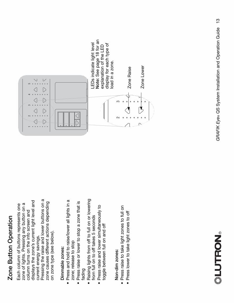
Zo
ne B
utto
n O
per
atio
nE
ach
colu
mn
of b
utto
ns r
epre
sent
s on
ezo
ne o
f lig
hts.
Pre
ssin
g an
y b
utto
n on
aco
lum
n tu
rns
on t
he in
fo s
cree
n an
dd
isp
lays
the
zon
e’s
curr
ent
light
leve
l and
curr
ent
ener
gy s
avin
gs.
Pre
ssin
g th
e ra
ise
and
low
er b
utto
ns o
n a
zone
cau
ses
diff
eren
t ac
tions
dep
end
ing
on z
one
typ
e (s
ee b
elow
).
Dim
mab
le z
ones
:•
Pre
ss a
nd h
old
to r
aise
/low
er a
ll lig
hts
in a
zone
; rel
ease
to
stop
•P
ress
rai
se o
r lo
wer
to
stop
a z
one
that
isfa
ding
•R
aisi
ng li
ghts
from
off
to fu
ll on
or
low
erin
gfr
om fu
ll on
to
off t
akes
5 s
econ
ds•
Pre
ss r
aise
and
low
er s
imul
tane
ousl
y to
togg
le b
etw
een
full
on a
nd o
ff
Non
-dim
zon
es:
•P
ress
rai
se t
o ta
ke li
ght
zone
s to
full
on•
Pre
ss lo
wer
to
take
ligh
t zo
nes
to o
ff
RG
RA
FIK
Eye
®Q
SS
yste
m In
stal
latio
n an
d O
per
atio
n G
uid
e
13
1
2
3
4
5
2
3
Zon
e R
aise
Zon
e Lo
wer
LED
s in
dic
ate
light
leve
lN
ote
: See
pag
e 18
for
an
exp
lana
tion
of t
he L
ED
dis
pla
y fo
r ea
ch t
ype
oflo
ad in
a z
one.
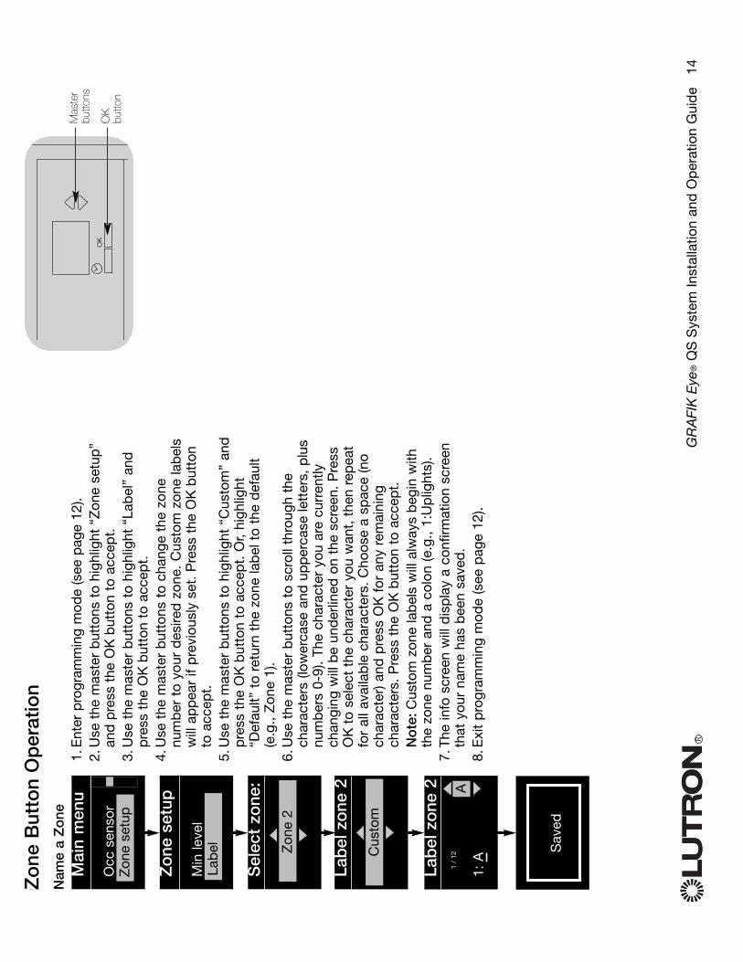
RG
RA
FIK
Eye
®Q
SS
yste
m In
stal
latio
n an
d O
per
atio
n G
uid
e
14
Zo
ne B
utto
n O
per
atio
nN
ame
a Z
one
1.E
nter
pro
gram
min
g m
ode
(see
pag
e 12
).2.
Use
the
mas
ter
but
tons
to
high
light
“Z
one
setu
p”
and
pre
ss t
he O
Kb
utto
n to
acc
ept.
3.U
se t
he m
aste
r b
utto
ns t
o hi
ghlig
ht “
Lab
el”
and
pre
ss t
he O
Kb
utto
n to
acc
ept.
4.U
se t
he m
aste
r b
utto
ns t
o ch
ange
the
zon
enu
mb
er t
o yo
ur d
esire
d z
one.
Cus
tom
zon
e la
bel
sw
ill a
pp
ear
if p
revi
ousl
y se
t. P
ress
the
OK
but
ton
to a
ccep
t.5.
Use
the
mas
ter
but
tons
to
high
light
“C
usto
m”
and
pre
ss t
he O
Kb
utto
n to
acc
ept.
Or,
high
light
“Def
ault”
to
retu
rn t
he z
one
lab
el t
o th
e d
efau
lt(e
.g.,
Zon
e 1)
.6.
Use
the
mas
ter
but
tons
to
scro
ll th
roug
h th
ech
arac
ters
(low
erca
se a
nd u
pp
erca
se le
tter
s, p
lus
num
ber
s 0-
9).
The
char
acte
r yo
u ar
e cu
rren
tlych
angi
ng w
ill b
e un
der
lined
on
the
scre
en.
Pre
ssO
Kto
sel
ect
the
char
acte
r yo
u w
ant,
the
n re
pea
tfo
r al
l ava
ilab
le c
hara
cter
s. C
hoos
e a
spac
e (n
och
arac
ter)
and
pre
ss O
K f
or a
ny r
emai
ning
char
acte
rs.
Pre
ss t
he O
Kb
utto
n to
acc
ept.
No
te:C
usto
m z
one
lab
els
will
alw
ays
beg
in w
ithth
e zo
ne n
umb
er a
nd a
col
on (e
.g.,
1:U
plig
hts)
.7.
The
info
scr
een
will
dis
pla
y a
conf
irmat
ion
scre
enth
at y
our
nam
e ha
s b
een
save
d.
8.E
xit
pro
gram
min
g m
ode
(see
pag
e 12
).
Mai
n m
enu
Occ
sen
sor
Sce
ne s
etup
Zon
e se
tup
Zo
ne s
etup
Min
leve
l
Sel
ect
zone
:
Zon
e 2
Lab
el
Lab
el z
one
2
Cus
tom
Lab
el z
one
2
1: A
A1
/12
OK
Mas
ter
butto
ns
OK
bu
tton
Sav
ed Sav
ed
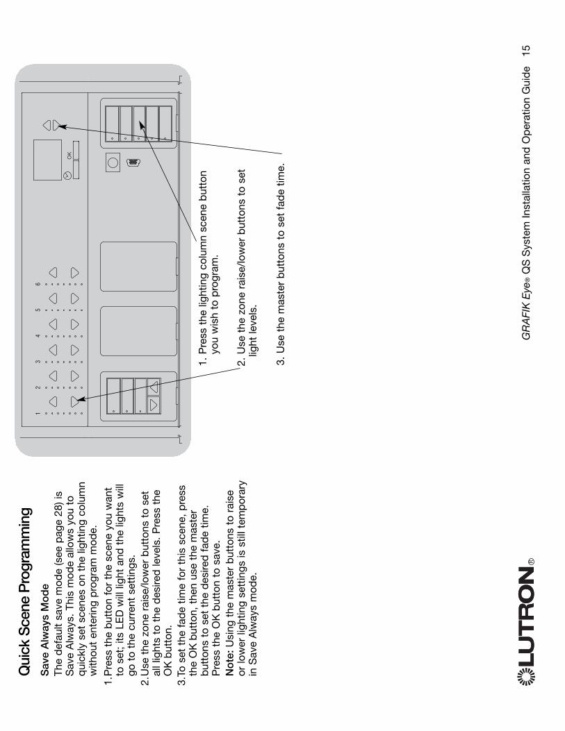
Qui
ck S
cene
Pro
gram
min
gS
ave
Alw
ays
Mo
de
The
def
ault
save
mod
e (s
ee p
age
28) i
sS
ave
Alw
ays.
Thi
s m
ode
allo
ws
you
toq
uick
ly s
et s
cene
s on
the
ligh
ting
colu
mn
with
out
ente
ring
pro
gram
mod
e.
1.P
ress
the
but
ton
for
the
scen
e yo
u w
ant
to s
et;
its L
ED
will
ligh
t an
d t
he li
ghts
will
go t
o th
e cu
rren
t se
ttin
gs.
2.U
se t
he z
one
rais
e/lo
wer
but
tons
to
set
all l
ight
s to
the
des
ired
leve
ls.
Pre
ss t
heO
Kb
utto
n.3.
To s
et t
he f
ade
time
for
this
sce
ne,
pre
ssth
e O
Kb
utto
n, t
hen
use
the
mas
ter
but
tons
to
set
the
des
ired
fad
e tim
e.P
ress
the
OK
but
ton
to s
ave.
No
te:U
sing
the
mas
ter
but
tons
to
rais
eor
low
er li
ghtin
g se
ttin
gs is
stil
l tem
por
ary
in S
ave
Alw
ays
mod
e.
RG
RA
FIK
Eye
®Q
SS
yste
m In
stal
latio
n an
d O
per
atio
n G
uid
e
15
OK
1
2
3
4
5
6
1. P
ress
the
ligh
ting
colu
mn
scen
e b
utto
nyo
u w
ish
to p
rogr
am.
2. U
se t
he z
one
rais
e/lo
wer
but
tons
to
set
light
leve
ls.
3. U
se t
he m
aste
r b
utto
ns t
o se
t fa
de
time.

Sce
ne S
etup
Pro
gra
m a
Sce
ne1.
Ent
er p
rogr
amm
ing
mod
e (s
ee p
age
12).
2.U
se t
he m
aste
r b
utto
ns t
o hi
ghlig
ht “
Sce
ne s
etup
” an
dp
ress
the
OK
but
ton
to a
ccep
t.3.
Use
the
mas
ter
but
tons
to
sele
ct “
Leve
ls”
to a
dju
st li
ghtin
gan
d/o
r w
ind
ow t
reat
men
t le
vels
. P
ress
the
OK
but
ton
toac
cep
t. U
s th
e m
aste
r b
utto
ns t
o se
lect
the
sce
ne n
umb
erof
you
r d
esire
d s
cene
. P
ress
the
OK
but
ton
to a
ccep
t.4.
Set
eac
h zo
ne t
o th
e d
esire
d li
ght
leve
l for
thi
s sc
ene
usin
gth
e zo
ne r
aise
/low
er b
utto
ns.
The
info
scr
een
will
dis
pla
yth
e zo
ne a
nd p
erce
ntag
e as
you
ad
just
it.
To s
et a
zon
e as
una
ffect
ed,
low
er t
he li
ght
leve
ls a
ll th
ew
ay t
o of
f, th
en h
old
the
zon
e lo
wer
but
ton
for
3 se
cond
s.W
hen
all z
ones
are
at
the
des
ired
leve
l, p
ress
the
OK
but
ton
to a
ccep
t.5.
Use
the
mas
ter
but
tons
to
set
the
fad
e tim
e fo
r th
is s
cene
.P
ress
the
OK
but
ton
to a
ccep
t.6.
Pre
ss t
he b
utto
n on
a s
had
e co
lum
n th
at w
ill t
ake
the
win
dow
tre
atm
ents
ass
igne
d t
o th
at s
had
e co
lum
n to
the
leve
l you
wan
t fo
r th
is s
cene
. R
epea
t fo
r an
y ad
diti
onal
shad
e co
lum
ns.
Pre
ss t
he O
Kb
utto
n to
acc
ept.
Or,
if yo
ud
o no
t ha
ve o
r d
o no
t w
ish
to s
et s
had
e gr
oup
s fo
r th
issc
ene,
pre
ss O
K.
7.Th
e in
fo s
cree
n w
ill d
isp
lay
a co
nfirm
atio
n sc
reen
tha
t yo
ursc
ene
has
bee
n sa
ved
.8.
Exi
t p
rogr
amm
ing
mod
e (s
ee p
age
12).
RG
RA
FIK
Eye
®Q
SS
yste
m In
stal
latio
n an
d O
per
atio
n G
uid
e
16
OK
Mas
ter
butto
ns
OK
bu
tton
Mai
n m
enu
Tim
eclo
ckS
cene
set
up
Sce
ne s
etup
Lab
els
Sce
ne s
etup
Leve
ls
Sce
ne s
etup
Sce
ne 1
Ad
just
fad
e3
seco
nds
Sce
ne 1
Set
sha
de
grou
ps
3
seco
nds
Sce
ne 1
Set
zon
es
Sce
ne 1
Sav
ed Sav
ed
1
2
3
4
5
2
3
Zon
e R
aise
Zon
e Lo
wer

RG
RA
FIK
Eye
®Q
SS
yste
m In
stal
latio
n an
d O
per
atio
n G
uid
e
17
Sce
ne S
etup
Nam
e a
Sce
ne1.
Ent
er p
rogr
amm
ing
mod
e (s
ee p
age
12).
2.U
se t
he m
aste
r b
utto
ns t
o hi
ghlig
ht “
Sce
ne s
etup
”an
d p
ress
the
OK
but
ton
to a
ccep
t.3.
Use
the
mas
ter
but
tons
to
high
light
“La
bel
s” a
ndp
ress
the
OK
but
ton
to a
ccep
t.4.
Use
the
mas
ter
but
tons
to
chan
ge t
he s
cene
num
ber
to
your
des
ired
sce
ne.
Pre
ss t
he O
Kb
utto
n to
acc
ept.
5.U
se t
he m
aste
r b
utto
ns t
o hi
ghlig
ht “
Cus
tom
” an
dp
ress
the
OK
but
ton
to a
ccep
t.6.
Use
the
mas
ter
but
tons
to
scro
ll th
roug
h th
ech
arac
ters
(low
erca
se a
nd u
pp
erca
se le
tter
s, p
lus
num
ber
s 0-
9).
The
char
acte
r yo
u ar
e cu
rren
tlych
angi
ng w
ill b
e un
der
lined
on
the
scre
en.
Pre
ssO
Kto
sel
ect
the
char
acte
r yo
u w
ant,
the
n re
pea
tfo
r al
l ava
ilab
le c
hara
cter
s. C
hoos
e a
spac
e (n
och
arac
ter)
and
pre
ss O
K f
or a
ny r
emai
ning
char
acte
rs.
Pre
ss t
he O
Kb
utto
n to
acc
ept.
7.Th
e in
fo s
cree
n w
ill d
isp
lay
a co
nfirm
atio
n sc
reen
that
you
r na
me
has
bee
n sa
ved
.8.
Exi
t p
rogr
amm
ing
mod
e (s
ee p
age
12).
Mai
n m
enu
Occ
sen
sor
Sce
ne s
etup
Sce
ne s
etup
Lab
els
Sel
ect
scen
e:
Sce
ne 1
Labe
l sce
ne 1
Cus
tom
Labe
l sce
ne 1
1: A
A1
/11
OK
Mas
ter
butto
ns
OK
bu
tton
Sce
ne s
etup
Leve
lsLa
bel
sLa
bel
s
Sav
ed Sav
ed

LED
Dis
pla
ys f
or
Lig
htin
g L
evel
sD
imm
able
Lig
hts
No
n-D
im L
ight
s
Off
1-17
%
18-3
4%
35-5
1%
52-6
8%
69-8
5%
86-9
9%
On/
100%
Una
ffec
ted
(ligh
ts a
re n
ot a
ffect
ed
by s
cene
but
ton
or m
aste
r ra
ise/
low
er)
RG
RA
FIK
Eye
®Q
SS
yste
m In
stal
latio
n an
d O
per
atio
n G
uid
e
18
Lege
nd:
LED
litLE
D o
ff

Set
ting
Lim
itsN
ote
:Ent
erin
g Li
mit
Set
up m
ode
may
cau
se w
ind
ow t
reat
men
ts t
om
ove
app
roxi
mat
ely
8 in
ches
up
or d
own.
Be
sure
tha
t ea
chw
ind
ow
tre
atm
ent
is p
osi
tione
dso
tha
t th
e fa
bric
can
saf
ely
mo
ve 8
inch
es u
p o
r d
ow
nb
efo
re e
nter
ing
Lim
it S
etup
mo
de.
1.O
n an
y sh
ade
colu
mn,
pre
ss a
nd h
old
sim
ulta
neou
sly
the
top
and
rai
se b
utto
ns.
The
LED
s ne
xt t
o th
e to
pan
d b
otto
m b
utto
ns w
illcy
cle.
N
ote
:At
any
time
whi
lein
Lim
it S
etup
mod
e,yo
u ca
n m
ove
all
win
dow
tre
atm
ents
toge
ther
to
thei
r cu
rren
top
en li
mit
by
dou
ble
-ta
pp
ing
the
top
but
ton,
or t
o th
eir
curr
ent
clos
elim
it b
y d
oub
le-t
app
ing
the
bot
tom
but
ton.
N
ote
:Onc
e E
DU
s (e
lect
roni
c d
rive
units
of t
he w
ind
ow t
reat
men
t) ha
ve b
een
assi
gned
to
shad
e co
lum
ns,
limits
can
be
set
for
an E
DU
only
usi
ng t
he s
had
eco
lum
n it
is a
ssig
ned
to,
and
a s
had
eco
lum
n ca
n se
t lim
its o
nly
for
thos
e E
DU
sas
sign
ed t
o it.
2.S
elec
t th
e E
DU
you
wan
t to
to
adju
stus
ing
the
top
but
ton
on t
he s
had
eco
lum
n. E
ach
time
you
pre
ss a
nd r
elea
seth
e to
p b
utto
n, a
diff
eren
t E
DU
tha
t is
assi
gned
to
that
sha
de
colu
mn
will
op
enan
d c
lose
in a
n 8-
inch
ran
ge t
o in
dic
ate
itis
sel
ecte
d.
Pre
ss t
he t
op b
utto
n un
til t
heE
DU
for
the
win
dow
tre
atm
ent
you
wis
hto
ad
just
mov
es.
(You
can
als
o us
e th
eb
otto
m b
utto
n, w
hich
mov
es t
hrou
gh t
heas
sign
ed E
DU
s in
the
op
pos
ite o
rder
.)3.
Ad
just
the
cur
rent
ly s
elec
ted
ED
U t
o th
e d
esire
d le
vel f
orth
e op
en li
mit
(the
max
imum
the
win
dow
tre
atm
ent
isal
low
ed t
o op
en) u
sing
the
rais
e an
d lo
wer
but
tons
.4.
Pre
ss a
nd h
old
the
top
but
ton
on t
hesh
ade
colu
mn
for
5 se
cond
s to
sto
re t
hecu
rren
t p
ositi
on a
s th
e op
en li
mit.
The
LED
next
to
the
top
but
ton
will
fla
shq
uick
ly f
or 2
sec
ond
s.5.
Ad
just
the
cur
rent
ly s
elec
ted
ED
U t
o th
ed
esire
d le
vel f
or t
he c
lose
lim
it (th
em
axim
um t
he w
ind
ow t
reat
men
t is
allo
wed
to
clos
e) u
sing
the
rai
se a
ndlo
wer
but
tons
.6.
Pre
ss a
nd h
old
the
bot
tom
but
ton
on t
hesh
ade
colu
mn
for
5 se
cond
s to
sto
re t
hecu
rren
t p
ositi
on a
s th
e cl
ose
limit.
The
LED
next
to
the
bot
tom
but
ton
will
fla
shq
uick
ly f
or 2
sec
ond
s.7.
Rep
eat
step
s 2
thro
ugh
6 to
set
the
op
enan
d c
lose
lim
its f
or e
ach
win
dow
trea
tmen
t as
sign
ed t
o th
e sh
ade
colu
mn.
8.P
ress
and
hol
d s
imul
tane
ousl
y th
e to
pan
d r
aise
but
tons
on
the
shad
e co
lum
n to
exit
Lim
it S
etup
mod
e.
RG
RA
FIK
Eye
®Q
SS
yste
m In
stal
latio
n an
d O
per
atio
n G
uid
e
19
Ad
just
ing
Win
do
w T
reat
men
t S
ettin
gs
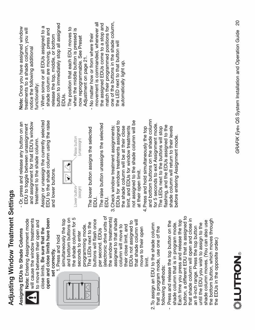
Ass
igni
ng E
DU
s to
Sha
de
Co
lum
nsN
ote
:Ent
erin
g A
ssig
nmen
t m
ode
will
cau
se t
he w
ind
ow t
reat
men
tsto
mov
e b
etw
een
thei
r op
en a
ndcl
ose
limits
. Be
sure
tha
t th
eo
pen
and
clo
se li
mits
hav
e b
een
set
corr
ectly
.1.
Pre
ss a
nd h
old
sim
ulta
neou
sly
the
top
and
bot
tom
but
tons
on
the
shad
e co
lum
n fo
r 5
seco
nds
to e
nter
pro
gram
min
g m
ode.
The
LED
s ne
xt t
o th
eb
utto
ns w
ill f
lash
onc
ep
er s
econ
d.
ED
Us
(ele
ctro
nic
driv
e un
its o
fth
e w
ind
ow t
reat
men
ts)
assi
gned
to
that
sha
de
colu
mn
will
mov
e to
thei
r cl
ose
limit,
and
ED
Us
not
assi
gned
to
that
sha
de
colu
mn
will
mov
e to
the
ir op
enlim
it.2.
To a
ssig
n an
ED
U t
o th
e sh
ade
colu
mn
that
is p
rogr
am m
ode,
use
one
of
the
follo
win
g m
etho
ds:
- P
ress
and
rel
ease
the
top
but
ton
on t
hesh
ade
colu
mn
that
is in
pro
gram
mod
e.E
ach
time
you
pre
ss a
nd r
elea
se t
he t
opb
utto
n, a
diff
eren
t E
DU
tha
t is
ass
igne
d t
oth
at s
had
e co
lum
n w
ill o
pen
and
clo
se in
an 8
-inc
h ra
nge.
Pre
ss t
he t
op b
utto
nun
til t
he E
DU
you
wis
h to
ass
ign
to t
hesh
ade
colu
mn
mov
es.
(You
can
als
o us
eth
e b
otto
m b
utto
n, w
hich
mov
es t
hrou
ghth
e E
DU
s in
the
op
pos
ite o
rder
.)
- O
r, p
ress
and
rel
ease
any
but
ton
on a
nE
DU
to
togg
le b
etw
een
unas
sign
men
tan
d a
ssig
nmen
t fo
r th
at E
DU
’s w
ind
owtr
eatm
ent
to t
he s
had
e co
lum
n.A
ssig
n or
una
ssig
n th
e cu
rren
tly s
elec
ted
ED
U t
o th
e sh
ade
colu
mn
usin
g th
e ra
ise
and
low
er b
utto
ns.
The
low
er b
utto
n as
sign
s th
e se
lect
edE
DU
.Th
e ra
ise
but
ton
unas
sign
s th
e se
lect
edE
DU
.3.
Che
ck w
ind
ow t
reat
men
t as
sign
men
ts:
ED
Us
for
win
dow
tre
atm
ents
ass
igne
d t
oth
e sh
ade
colu
mn
will
be
at t
heir
clos
elim
it, a
nd E
DU
s fo
r w
ind
ow t
reat
men
tsno
t as
sign
ed t
o th
e sh
ade
colu
mn
will
be
at t
heir
open
lim
it.4.
Pre
ss a
nd h
old
sim
ulta
neou
sly
the
top
and
bot
tom
but
tons
on
the
shad
e co
lum
nfo
r 5
seco
nds
to e
xit
Ass
ignm
ent
mod
e.Th
e LE
Ds
next
to
the
but
tons
will
sto
pfla
shin
g, a
nd t
he E
DU
s as
sign
ed t
o th
esh
ade
colu
mn
will
ret
urn
to t
heir
leve
lsb
efor
e en
terin
g A
ssig
nmen
t m
ode.
No
te:O
nce
you
have
ass
igne
d w
ind
owtr
eatm
ents
to
a sh
ade
colu
mn,
you
will
notic
e th
e fo
llow
ing
add
ition
alfu
nctio
nalit
y:-
Whe
n so
me
or a
ll E
DU
s as
sign
ed t
o a
shad
e co
lum
n ar
e m
ovin
g, p
ress
and
rele
ase
the
top
, m
idd
le,
or b
otto
mb
utto
n to
imm
edia
tely
sto
p a
ll as
sign
edE
DU
s.
- Th
e p
ositi
on t
hat
each
ED
U m
oves
to
whe
n th
e m
idd
le b
utto
n is
pre
ssed
isno
w r
epro
gram
mab
le.
See
Pre
set
Ad
just
men
t on
pag
e 21
.-
No
mat
ter
how
or
from
whe
re t
heir
mov
emen
t is
com
man
ded
, w
hene
ver
all
the
assi
gned
ED
Us
com
e to
a s
top
and
mat
ch t
heir
pro
gram
med
pos
ition
s fo
ron
e of
the
but
tons
in t
he s
had
e co
lum
n,th
e LE
D n
ext
to t
hat
but
ton
will
auto
mat
ical
ly li
ght
up.
RG
RA
FIK
Eye
®Q
SS
yste
m In
stal
latio
n an
d O
per
atio
n G
uid
e
20
Low
er b
utto
n(a
ssig
n)R
aise
but
ton
(una
sssi
gn)
Ad
just
ing
Win
do
w T
reat
men
t S
ettin
gs

Pre
set
Ad
just
men
t:S
imp
le M
etho
d1.
Use
the
rai
se a
nd lo
wer
but
tons
on
the
shad
eco
lum
n to
set
all
ED
Us
(ele
ctro
nic
driv
e un
its o
fth
e w
ind
ow t
reat
men
ts)
to t
he d
esire
d p
rese
tle
vels
.2.
Pre
ss a
nd h
old
the
mid
dle
but
ton
on t
hesh
ade
colu
mn
for
5se
cond
s to
sav
e th
eE
DU
pre
set
pos
ition
s.Th
e LE
D n
ext
to t
heb
utto
n w
ill f
lash
and
then
ligh
t co
ntin
uous
ly,
ind
icat
ing
the
pre
set
has
bee
n st
ored
.N
ote
:Onc
e E
DU
pre
sets
hav
e b
een
assi
gned
to
but
tons
on
a sh
ade
colu
mn,
thos
e p
rese
ts a
re a
cces
sib
le f
or a
n E
DU
only
usi
ng t
he s
had
e co
lum
n it
isas
sign
ed t
o, a
nd a
sha
de
colu
mn
can
acce
ss p
rese
t le
vels
onl
y fo
r th
ose
ED
Us
assi
gned
to
it.
Pre
set
Ad
just
men
t:A
dva
nced
Met
hod
No
te: T
he a
dva
nced
met
hod
for
ad
just
ing
pre
sets
is n
eed
ed o
nly
if yo
u w
ish
to h
ave
the
win
dow
tre
atm
ents
ass
igne
d t
o th
esh
ade
colu
mn
set
at d
iffer
ent
pos
ition
s in
the
pre
set.
If,
how
ever
, yo
u w
ish
all t
hew
ind
ow t
reat
men
ts in
the
gro
up t
o b
elin
ed u
p w
ith o
ne a
noth
er in
the
pre
set,
you
shou
ld u
se t
he S
imp
le M
etho
d a
t le
ft.
No
te:E
nter
ing
Ass
ignm
ent
mod
e w
illca
use
the
win
dow
tre
atm
ents
to
mov
eb
etw
een
thei
r op
en a
nd c
lose
lim
its. B
esu
re t
hat
the
op
en a
nd c
lose
lim
its h
ave
bee
n se
t co
rrec
tly.
1.O
n th
e sh
ade
colu
mn
who
se p
rese
t yo
u w
ish
to a
dju
st,
pre
ss a
ndho
ld s
imul
tane
ousl
y th
eto
p a
nd b
otto
mb
utto
ns.
The
LED
s ne
xtto
the
but
tons
will
fla
sh.
ED
Us
(ele
ctro
nic
driv
eun
its) f
or t
he a
ssig
ned
win
dow
tre
atm
ents
will
mov
e to
the
ir cl
osed
limits
, an
d E
DU
s fo
run
assi
gned
win
dow
trea
tmen
ts w
ill m
ove
toth
eir
open
lim
its.
2.P
ress
and
rel
ease
the
mid
dle
but
ton
onth
at s
had
e co
lum
n. T
he a
dja
cent
LE
D w
illb
link
rap
idly
. E
DU
s fo
r as
sign
ed w
ind
owtr
eatm
ents
will
aut
omat
ical
ly m
ove
toth
eir
curr
ent
pre
set
sett
ings
. 3.
Use
the
rai
se a
nd lo
wer
but
tons
to
mov
e al
l ED
Us
for
assi
gned
win
dow
trea
tmen
ts t
oget
her
to t
hed
esire
d p
rese
t se
ttin
g.
4.To
mov
e an
ED
U in
div
idua
lly t
o its
des
ired
pre
set
sett
ing,
sel
ect
the
ED
Uus
ing
the
top
but
ton
on t
he s
had
eco
lum
n. E
ach
time
you
pre
ss a
nd r
elea
seth
e to
p b
utto
n, a
diff
eren
t E
DU
tha
t is
assi
gned
to
that
sha
de
colu
mn
will
op
enan
d c
lose
in a
n 8-
inch
ran
ge.
Pre
ssre
pea
ted
ly u
ntil
the
ED
U f
or t
he w
ind
owtr
eatm
ent
you
wis
h to
ad
just
mov
es.
Ad
just
tha
t E
DU
to
the
des
ired
hei
ght
usin
g th
e ra
ise
and
low
er b
utto
ns.
Rep
eat
this
ste
p f
or a
ll as
sign
ed E
DU
s.5.
Onc
e yo
u ar
e sa
tisfie
d t
hat
all t
heas
sign
ed E
DU
s ar
e se
t to
the
pos
ition
syo
u w
ant
to a
ssig
n as
the
pre
set,
pre
ssan
d h
old
the
mid
dle
but
ton
on t
he s
had
eco
lum
n fo
r 5
seco
nds.
The
pre
set
will
be
save
d.
6.P
ress
and
hol
d s
imul
tane
ousl
y th
e to
pan
d b
otto
m b
utto
ns o
n th
e sh
ade
colu
mn
for
5 se
cond
s to
exi
t to
nor
mal
mod
e.Th
e LE
Ds
next
to
the
but
tons
will
sto
pfla
shin
g.
RG
RA
FIK
Eye
®Q
SS
yste
m In
stal
latio
n an
d O
per
atio
n G
uid
e
21
Ad
just
ing
Win
do
w T
reat
men
t S
ettin
gs

RG
RA
FIK
Eye
®Q
SS
yste
m In
stal
latio
n an
d O
per
atio
n G
uid
e
22
Ad
just
ing
Win
do
w T
reat
men
t S
ettin
gs
Nam
e a
Gro
up o
f W
ind
ow
Tre
atm
ents
1.E
nter
pro
gram
min
g m
ode
(see
pag
e 12
).2.
Use
the
mas
ter
but
tons
to
high
light
“S
had
e la
bel
s” a
nd p
ress
the
OK
but
ton
to a
ccep
t.3.
Use
the
mas
ter
but
tons
to
sele
ct y
our
des
ired
sha
de
grou
p.
Pre
ss t
he O
Kb
utto
n to
acc
ept.
4.U
se t
he m
aste
r b
utto
ns t
o hi
ghlig
ht “
Cus
tom
” an
d p
ress
the
OK
but
ton
to a
ccep
t.5.
Use
the
mas
ter
but
tons
to
scro
ll th
roug
h th
e ch
arac
ters
(low
erca
se a
nd u
pp
erca
sele
tter
s, p
lus
num
ber
s 0-
9).
The
char
acte
r yo
u ar
e cu
rren
tly c
hang
ing
will
be
und
erlin
ed o
n th
e sc
reen
. P
ress
OK
to s
elec
t th
e ch
arac
ter
you
wan
t, t
hen
rep
eat
for
all a
vaila
ble
cha
ract
ers.
Cho
ose
a sp
ace
(no
char
acte
r) a
nd p
ress
OK
for
any
rem
aini
ng c
hara
cter
s. P
ress
the
OK
but
ton
to a
ccep
t.6.
The
info
scr
een
will
dis
pla
y a
conf
irmat
ion
scre
en t
hat
your
nam
e ha
s b
een
save
d.
7.E
xit
pro
gram
min
g m
ode
(see
pag
e 12
).
Mai
n m
enu
Zon
e s
etup
Sha
de
lab
els
Sele
ct s
hade
grp
:
Sha
de
grp
1
Labe
l sha
de g
rp:
Cus
tom
Labe
l sha
de g
rp 1
1: A1 /
11
OK
Sav
ed Sav
edA
Mas
ter
butto
ns
OK
bu
tton
Rem
ote
ly R
esto
re E
DU
s to
Fac
tory
Def
aults
War
ning
!Res
torin
g an
ED
U(e
lect
roni
c d
rive
unit
for
a w
ind
owtr
eatm
ent)
to it
s fa
ctor
y d
efau
ltsw
ill e
rase
any
pre
viou
sp
rogr
amm
ing
or a
ssig
nmen
ts y
ouha
ve m
ade
for
that
ED
U.
No
te:E
nter
ing
this
mod
e m
ayca
use
win
dow
tre
atm
ents
to
mov
e ap
pro
xim
atel
y 8
inch
es u
por
dow
n. B
e su
re t
hat
each
win
do
w t
reat
men
t is
po
sitio
ned
so t
hat
the
fab
ric c
an s
afel
ym
ove
8 in
ches
up
or
do
wn
bef
ore
ent
erin
g t
his
mo
de.
1.O
n an
y sh
ade
colu
mn,
pre
ss a
nd h
old
sim
ulta
neou
sly
the
top
and
low
er b
utto
ns.
The
LED
nex
t to
the
top
but
ton
will
fla
sh.
2.P
ress
and
hol
d t
he t
opb
utto
n fo
r 5
seco
nds.
All
shad
e co
lum
nLE
Ds
will
blin
k ra
pid
ly.
3.S
elec
t th
e E
DU
you
wan
t to
res
tore
to
fact
ory
def
aults
usi
ng t
he t
op b
utto
n on
the
shad
e co
lum
n. E
ach
time
you
pre
ssan
d r
elea
se t
he t
op b
utto
n, a
diff
eren
tE
DU
in y
our
syst
em w
ill o
pen
and
clo
sein
an
8-in
ch r
ange
to
ind
icat
e it
isse
lect
ed.
Pre
ss t
he t
op b
utto
n un
til t
he
ED
U f
or t
he w
ind
ow t
reat
men
t yo
u w
ish
to r
esto
re t
o fa
ctor
y d
efau
lts m
oves
. (Y
ouca
n al
so u
se t
he b
otto
m b
utto
n, w
hich
mov
es t
hrou
gh t
he a
ssig
ned
ED
Us
in t
heop
pos
ite o
rder
.)4.
Pre
ss a
nd h
old
sim
ulta
neou
sly
the
rais
ean
d lo
wer
but
tons
for
5se
cond
s to
res
tore
the
mov
ing
shad
e to
fac
tory
def
aults
.5.
Rep
eat
step
s 3
and
4 t
o re
stor
e fa
ctor
yd
efau
lts t
o an
y ot
her
win
dow
tre
atm
ents
.6.
Pre
ss a
nd h
old
sim
ulta
neou
sly
the
top
and
low
er b
utto
ns o
n th
e sh
ade
colu
mn
to e
xit
this
mod
e.

RG
RA
FIK
Eye
®Q
SS
yste
m In
stal
latio
n an
d O
per
atio
n G
uid
e
23
Tim
eclo
ck O
per
atio
nS
et T
ime
and
Dat
e1.
Ent
er p
rogr
amm
ing
mod
e (s
ee p
age
12).
2.U
se t
he m
aste
r b
utto
ns t
o hi
ghlig
ht “
Tim
eclo
ck”
and
pre
ss t
he O
K b
utto
n to
acc
ept.
3. U
se t
he m
aste
r b
utto
ns t
o hi
ghlig
ht “
Tim
e &
dat
e”an
d p
ress
the
OK
but
ton
to a
ccep
t.4.
Use
the
mas
ter
but
tons
to
sele
ct b
etw
een
“12
Hr”
and
“24
Hr”
for
mat
for
tim
e d
isp
lay
and
pre
ss t
heO
Kb
utto
n to
acc
ept.
5. U
se t
he m
aste
r b
utto
ns t
o se
lect
the
cur
rent
hou
ran
d p
ress
the
OK
but
ton
to a
ccep
t. R
epea
t fo
r th
ecu
rren
t m
inut
es.
6. U
se t
he m
aste
r b
utto
ns t
o hi
ghlig
ht t
he c
urre
ntye
ar a
nd p
ress
the
OK
but
ton
to a
ccep
t. R
epea
tfo
r th
e cu
rren
t m
onth
and
dat
e.7.
The
info
scr
een
will
dis
pla
y a
conf
irmat
ion
scre
enth
at y
our
time
and
dat
e ha
ve b
een
save
d.
8.E
xit
pro
gram
min
g m
ode
(see
pag
e 12
).
OK
Mas
ter
butto
ns
OK
bu
tton
Mai
n m
enu
Tim
eclo
ckS
cene
set
up
Tim
eclo
ck
Hol
iday
Del
ete
even
tTi
me
&d
ate
Set
tim
e
: 00
A
M08
Tim
eclo
ck
Set
dat
e
Del
: 00 20
07
Set
dat
e
Set
fo
rmat
Del
: 00 12
Hr
Mar
ch
Set
dat
e
17
Set
tim
e
08 :
00
A
M30
Sav
ed Sav
ed
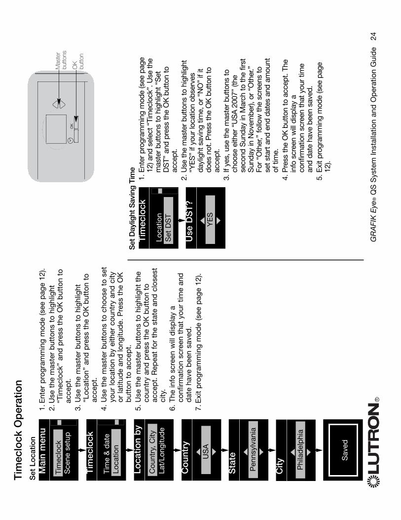
Set
Day
light
Sav
ing
Tim
e1.
Ent
er p
rogr
amm
ing
mod
e (s
ee p
age
12) a
nd s
elec
t “Ti
mec
lock
”. U
se th
em
aste
r bu
tton
s to
hig
hlig
ht “
Set
DS
T” a
nd p
ress
the
OK
butt
on to
acce
pt.
2. U
se th
e m
aste
r bu
tton
s to
hig
hlig
ht“Y
ES
” if
your
loca
tion
obse
rves
dayl
ight
sav
ing
time,
or
“NO
”if
itdo
es n
ot. P
ress
the
OK
butt
on to
acce
pt.
3. If
yes
, use
the
mas
ter
butt
ons
toch
oose
eith
er “
US
A20
07”
(the
seco
nd S
unda
y in
Mar
ch to
the
first
Sun
day
in N
ovem
ber),
or
“Oth
er.”
For
“Oth
er,”
follo
w th
e sc
reen
s to
set s
tart
and
end
dat
es a
nd a
mou
ntof
tim
e.4.
Pre
ss th
e O
Kbu
tton
to a
ccep
t. Th
ein
fo s
cree
n w
ill d
ispl
ay a
conf
irmat
ion
scre
en th
at y
our
time
and
date
hav
e be
en s
aved
.5.
Exi
t pro
gram
min
g m
ode
(see
pag
e12
).
RG
RA
FIK
Eye
®Q
SS
yste
m In
stal
latio
n an
d O
per
atio
n G
uid
e
24
Tim
eclo
ck O
per
atio
nS
et L
oca
tion
1.E
nter
pro
gram
min
g m
ode
(see
pag
e 12
).2.
Use
the
mas
ter
but
tons
to
high
light
“Tim
eclo
ck”
and
pre
ss t
he O
K b
utto
n to
acce
pt.
3. U
se t
he m
aste
r b
utto
ns t
o hi
ghlig
ht“L
ocat
ion”
and
pre
ss t
he O
Kb
utto
n to
acce
pt.
4. U
se t
he m
aste
r b
utto
ns t
o ch
oose
to
set
your
loca
tion
by
eith
er c
ount
ry a
nd c
ityor
latit
ude
and
long
itud
e. P
ress
the
OK
but
ton
to a
ccep
t.5.
Use
the
mas
ter
but
tons
to
high
light
the
coun
try
and
pre
ss t
he O
Kb
utto
n to
acce
pt.
Rep
eat
for
the
stat
e an
d c
lose
stci
ty.
6. T
he in
fo s
cree
n w
ill d
isp
lay
aco
nfirm
atio
n sc
reen
tha
t yo
ur t
ime
and
dat
e ha
ve b
een
save
d.
7.E
xit
pro
gram
min
g m
ode
(see
pag
e 12
).
OK
Mas
ter
butto
ns
OK
bu
tton
Mai
n m
enu
Tim
eclo
ckS
cene
set
up
Tim
eclo
ck
Tim
e &
dat
eD
elet
e ev
ent
Loca
tion
Loca
tion
by
Lat/
Long
itud
eC
ount
ry,
City
Tim
eclo
ck
Sta
te
Pen
nsyl
vani
a
City Phi
lad
elp
hia
Co
untr
y
08 :
00 US
A
Tim
eclo
ck
Loca
tion
Del
ete
even
tS
et D
ST
Use
DS
T?
Del
: 00 Y
ES
Sav
ed Sav
ed

RG
RA
FIK
Eye
®Q
SS
yste
m In
stal
latio
n an
d O
per
atio
n G
uid
e
25
Tim
eclo
ck O
per
atio
nA
dd
an
Eve
nt1.
Ent
er p
rogr
amm
ing
mod
e (s
ee p
age
12).
2.U
se t
he m
aste
r b
utto
ns t
o hi
ghlig
ht “
Tim
eclo
ck”
and
pre
ss t
he O
K b
utto
n to
acc
ept.
3. U
se t
he m
aste
r b
utto
ns t
o hi
ghlig
ht “
Ad
d e
vent
s”an
d p
ress
the
OK
but
ton
to a
ccep
t.4.
Use
the
mas
ter
but
tons
to
sele
ct t
he d
ay o
f th
ew
eek
for
this
eve
nt;
pre
ss t
he O
Kb
utto
n to
acce
pt.
5. U
se t
he m
aste
r b
utto
ns t
o se
lect
the
typ
e of
eve
nt(fi
xed
tim
e of
day
, or
rel
ativ
e to
sun
rise
or s
unse
t);p
ress
the
OK
but
ton
to a
ccep
t.6.
For
a f
ixed
-tim
e ev
ent,
use
the
mas
ter
but
tons
to
sele
ct t
he h
our
for
your
eve
nt t
o b
egin
; p
ress
the
OK
but
ton
to a
ccep
t. R
epea
t fo
r th
e m
inut
es.
For
a re
lativ
e tim
e ev
ent,
use
the
mas
ter
but
tons
and
the
OK
but
ton
to s
et t
he h
our,
then
the
min
utes
rel
ativ
e to
sun
rise
or s
unse
t (m
axim
um o
f1
hour
59
min
utes
bef
ore
or a
fter
sun
rise
orsu
nset
).7.
Use
the
mas
ter
but
tons
to
sele
ct t
he s
cene
you
wis
h to
act
ivat
e fo
r th
is e
vent
. Fo
r a
timec
lock
eve
nt in
volv
ing
only
sha
des
, sc
roll
thro
ugh
the
scen
es t
o fin
d t
he g
roup
of
shad
esan
d t
he a
ctio
n (1
, 2,
or
3; o
pen
, p
rese
t, o
r cl
ose)
you
wan
t to
ad
d t
o th
e tim
eclo
ck e
vent
. O
r, p
ress
the
but
ton
on t
he s
had
e co
lum
n th
atp
rod
uces
the
act
ion
you
wan
t to
ad
d t
o th
istim
eclo
ck e
vent
. P
ress
the
OK
but
ton
to a
ccep
t.8.
The
info
scr
een
will
dis
pla
y a
conf
irmat
ion
scre
enth
at y
our
even
t ha
s b
een
save
d.
9. E
xit
pro
gram
min
g m
ode
(see
pag
e 12
).
OK
Mas
ter
butto
ns
OK
bu
tton
Mai
n m
enu
Tim
eclo
ckS
cene
set
up
Tim
eclo
ck
Vie
w e
vent
sD
elet
e ev
ents
Ad
d e
vent
s
Tim
eclo
ck
Ad
d
Tim
e of
day
Ad
d Mon
day
Ad
d
Del
: 00
A
M08 A
dd
Sce
ne Sce
ne 1
Sav
ed Sav
ed

RG
RA
FIK
Eye
®Q
SS
yste
m In
stal
latio
n an
d O
per
atio
n G
uid
e
26
Tim
eclo
ck O
per
atio
nD
elet
e an
Eve
nt1.
Ent
er p
rogr
amm
ing
mod
e (s
ee p
age
12).
2.U
se t
he m
aste
r b
utto
ns t
o hi
ghlig
ht“T
imec
lock
” an
d p
ress
the
OK
but
ton
toac
cep
t.3.
Use
the
mas
ter
but
tons
to
high
light
“Del
ete
even
ts”
and
pre
ss t
he O
Kb
utto
nto
acc
ept.
4. U
se t
he m
aste
r b
utto
ns t
o se
lect
the
day
of t
he w
eek
(or
holid
ay) w
hen
the
even
toc
curs
; p
ress
the
OK
but
ton
to a
ccep
t.5.
Use
the
mas
ter
but
tons
to
sele
ct t
heev
ent
to d
elet
e; p
ress
the
OK
but
ton
toac
cep
t.6.
A s
cree
n w
ill a
pp
ear,
verif
ying
you
wis
h to
del
ete
the
even
t. P
ress
the
OK
but
ton
toac
cep
t an
d d
elet
e; o
ther
wis
e, p
ress
the
timec
lock
but
ton
to g
o b
ack.
7. T
he in
fo s
cree
n w
ill d
isp
lay
aco
nfirm
atio
n sc
reen
tha
t yo
ur e
vent
has
bee
n d
elet
ed.
8. E
xit
pro
gram
min
g m
ode
(see
pag
e 12
).
OK
Mas
ter
butto
ns
OK
but
ton
Tim
eclo
ckbu
tton
Mai
n m
enu
Tim
eclo
ckS
cene
set
up
Tim
eclo
ck
Cop
y sc
hed
ule
Del
ete
Tim
eclo
ck
Del
ete?
Del
ete
8:00
AM
Sce
ne 5
Del
ete
Mon
day
01/0
3
Vie
w a
n E
vent
1.E
nter
pro
gram
min
g m
ode
(see
pag
e 12
),se
lect
“Ti
mec
lock
,”an
d s
elec
t “V
iew
even
ts”.
2.U
se t
he m
aste
r b
utto
ns t
o se
lect
the
day
of t
he w
eek
(or
holid
ay) w
hen
the
even
toc
curs
; p
ress
the
OK
but
ton
to a
ccep
t.3.
Use
the
mas
ter
but
tons
to
sele
ct t
heev
ent
to v
iew
; p
ress
the
OK
but
ton
toac
cep
t.4.
Pre
ss t
he O
K b
utto
n to
ret
urn
to t
heTi
mec
lock
men
u.5.
Exi
t p
rogr
amm
ing
mod
e (s
ee p
age
12).
Tim
eclo
ck
Del
ete
even
tsA
dd
eve
nts
Vie
w e
vent
s
Mon
day
Vie
w
8:00
AM
Sce
ne 5
Vie
w e
vent
s
Mon
day
01/0
3
Del
ete
even
ts
Sav
ed Sav
ed
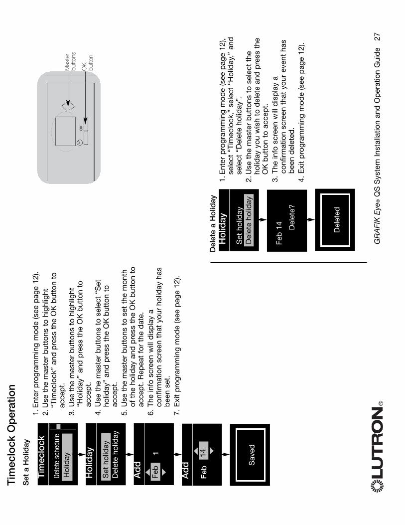
RG
RA
FIK
Eye
®Q
SS
yste
m In
stal
latio
n an
d O
per
atio
n G
uid
e
27
Tim
eclo
ck O
per
atio
nS
et a
Ho
liday
1.E
nter
pro
gram
min
g m
ode
(see
pag
e 12
).2.
Use
the
mas
ter
but
tons
to
high
light
“Tim
eclo
ck”
and
pre
ss t
he O
K b
utto
n to
acce
pt.
3. U
se t
he m
aste
r b
utto
ns t
o hi
ghlig
ht“H
olid
ay”
and
pre
ss t
he O
Kb
utto
n to
acce
pt.
4. U
se t
he m
aste
r b
utto
ns t
o se
lect
“S
etho
liday
” an
d p
ress
the
OK
but
ton
toac
cep
t.5.
Use
the
mas
ter
but
tons
to
set
the
mon
thof
the
hol
iday
and
pre
ss t
he O
Kb
utto
n to
acce
pt.
Rep
eat
for
the
dat
e.6.
The
info
scr
een
will
dis
pla
y a
conf
irmat
ion
scre
en t
hat
your
hol
iday
has
bee
n se
t.7.
Exi
t p
rogr
amm
ing
mod
e (s
ee p
age
12).
OK
Mas
ter
butto
ns
OK
bu
tton
Tim
eclo
ck
Dele
te s
ched
ule
Ho
liday
Ad
d e
vent
Del
ete
holid
ayS
et h
olid
ay
Hol
iday
Ad
d
1Fe
b
Mon
day
Ad
d
Feb
14D
elet
e a
Ho
liday
1.E
nter
pro
gram
min
g m
ode
(see
pag
e 12
),se
lect
“Ti
mec
lock
,”se
lect
“H
olid
ay,”
and
sele
ct “
Del
ete
holid
ay”.
2.U
se t
he m
aste
r b
utto
ns t
o se
lect
the
holid
ay y
ou w
ish
to d
elet
e an
d p
ress
the
OK
but
ton
to a
ccep
t.3.
The
info
scr
een
will
dis
pla
y a
conf
irmat
ion
scre
en t
hat
your
eve
nt h
asb
een
del
eted
.4.
Exi
t p
rogr
amm
ing
mod
e (s
ee p
age
12).
Ho
liday
Set
hol
iday
Del
ete
Del
ete
holid
ay
Mon
day
Feb
14
Del
ete?
Sav
ed Sav
ed
Sav
ed Del
eted
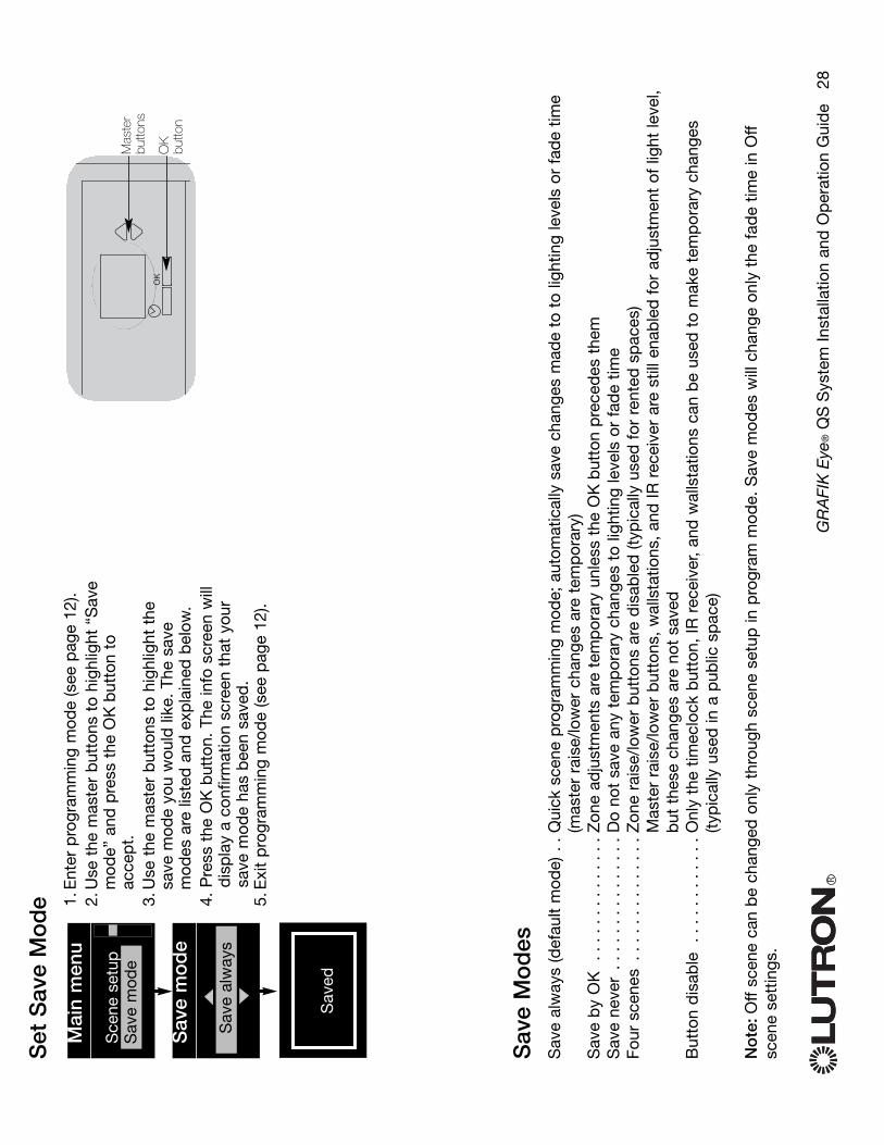
RG
RA
FIK
Eye
®Q
SS
yste
m In
stal
latio
n an
d O
per
atio
n G
uid
e
28
Set
Sav
e M
od
e 1.E
nter
pro
gram
min
g m
ode
(see
pag
e 12
).2.
Use
the
mas
ter
but
tons
to
high
light
“S
ave
mod
e” a
nd p
ress
the
OK
but
ton
toac
cep
t.3.
Use
the
mas
ter
but
tons
to
high
light
the
save
mod
e yo
u w
ould
like
. Th
e sa
vem
odes
are
list
ed a
nd e
xpla
ined
bel
ow.
4. P
ress
the
OK
but
ton.
The
info
scr
een
will
dis
pla
y a
conf
irmat
ion
scre
en t
hat
your
save
mod
e ha
s b
een
save
d.
5.E
xit
pro
gram
min
g m
ode
(see
pag
e 12
).
Mai
n m
enu
Sce
ne s
etup
Sav
e m
ode
Sav
e m
od
e
Sav
e al
way
s
Sav
e M
od
esS
ave
alw
ays
(def
ault
mod
e) .
.Qui
ck s
cene
pro
gram
min
g m
ode;
aut
omat
ical
ly s
ave
chan
ges
mad
e to
to
light
ing
leve
ls o
r fa
de
time
(mas
ter
rais
e/lo
wer
cha
nges
are
tem
por
ary)
Sav
e b
y O
K .
. . .
. . .
. . .
. . .
.Z
one
adju
stm
ents
are
tem
por
ary
unle
ss t
he O
Kb
utto
n p
rece
des
the
mS
ave
neve
r . .
. . .
. . .
. . .
. . .
.D
o no
t sa
ve a
ny t
emp
orar
y ch
ange
s to
ligh
ting
leve
ls o
r fa
de
time
Four
sce
nes
. . .
. . .
. . .
. . .
. .Z
one
rais
e/lo
wer
but
tons
are
dis
able
d (t
ypic
ally
use
d f
or r
ente
d s
pac
es)
Mas
ter
rais
e/lo
wer
but
tons
, w
alls
tatio
ns,
and
IR r
ecei
ver
are
still
ena
ble
d f
or a
dju
stm
ent
of li
ght
leve
l,b
ut t
hese
cha
nges
are
not
sav
edB
utto
n d
isab
le .
. . .
. . .
. . .
. .O
nly
the
timec
lock
but
ton,
IR r
ecei
ver,
and
wal
lsta
tions
can
be
used
to
mak
e te
mp
orar
y ch
ange
s (ty
pic
ally
use
d in
a p
ublic
sp
ace)
No
te:O
ff sc
ene
can
be
chan
ged
onl
y th
roug
h sc
ene
setu
p in
pro
gram
mod
e. S
ave
mod
es w
ill c
hang
e on
ly t
he f
ade
time
in O
ffsc
ene
sett
ings
.
OK
Mas
ter
butto
ns
OK
bu
tton
Sav
ed Sav
ed
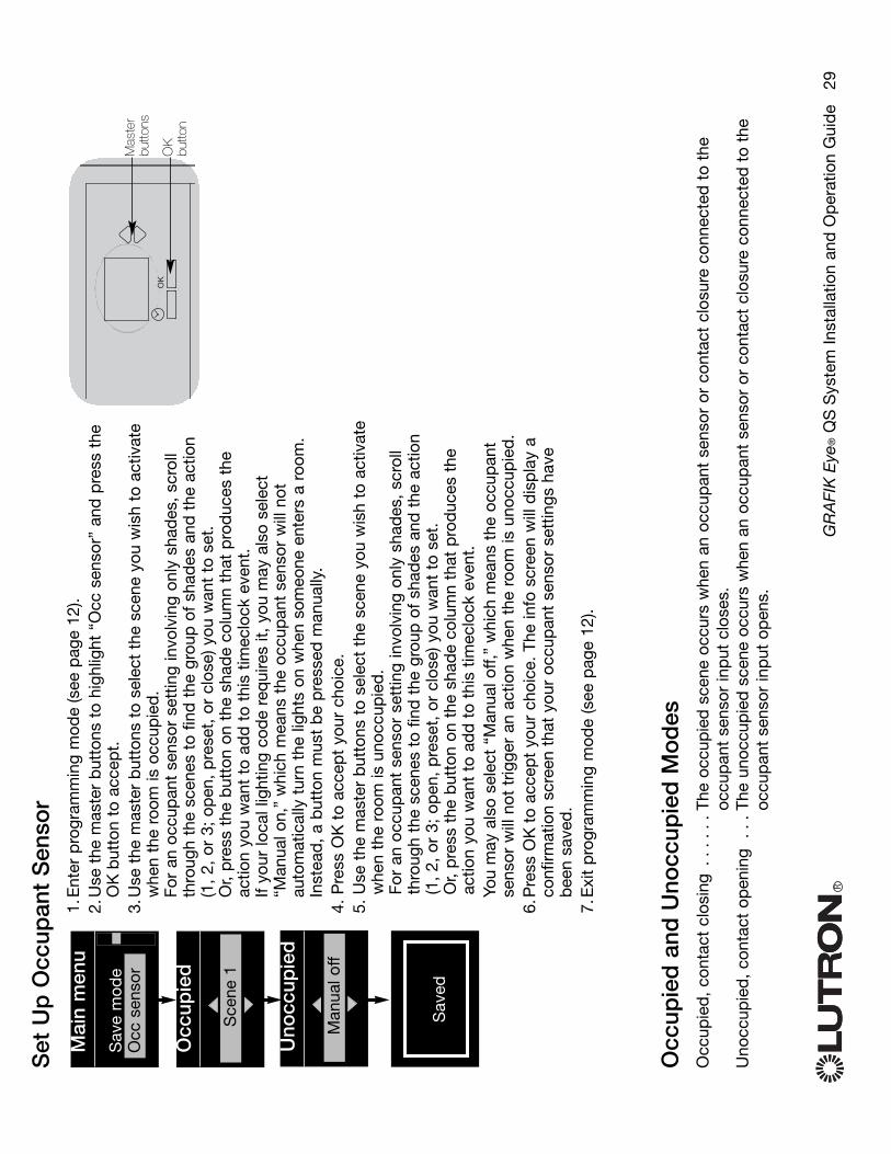
RG
RA
FIK
Eye
®Q
SS
yste
m In
stal
latio
n an
d O
per
atio
n G
uid
e
29
Set
Up
Occ
upan
t S
enso
r1.
Ent
er p
rogr
amm
ing
mod
e(s
ee p
age
12).
2.U
se t
he m
aste
r b
utto
ns t
o hi
ghlig
ht “
Occ
sen
sor”
and
pre
ss t
heO
Kb
utto
n to
acc
ept.
3.U
se t
he m
aste
r b
utto
ns t
o se
lect
the
sce
ne y
ou w
ish
to a
ctiv
ate
whe
n th
e ro
om is
occ
upie
d.
For
an o
ccup
ant
sens
or s
ettin
g in
volv
ing
only
sha
des
, sc
roll
thro
ugh
the
scen
es t
o fin
d t
he g
roup
of
shad
es a
nd t
he a
ctio
n(1
, 2,
or
3; o
pen
, p
rese
t, o
r cl
ose)
you
wan
t to
set
. O
r, p
ress
the
but
ton
on t
he s
had
e co
lum
n th
at p
rod
uces
the
actio
n yo
u w
ant
to a
dd
to
this
tim
eclo
ck e
vent
.If
your
loca
l lig
htin
g co
de
req
uire
s it,
you
may
als
o se
lect
“Man
ual o
n,”
whi
ch m
eans
the
occ
upan
t se
nsor
will
not
auto
mat
ical
ly t
urn
the
light
s on
whe
n so
meo
ne e
nter
s a
room
.In
stea
d,
a b
utto
n m
ust
be
pre
ssed
man
ually
.4.
Pre
ss O
Kto
acc
ept
your
cho
ice.
5. U
se t
he m
aste
r b
utto
ns t
o se
lect
the
sce
ne y
ou w
ish
to a
ctiv
ate
whe
n th
e ro
om is
uno
ccup
ied
.Fo
r an
occ
upan
t se
nsor
set
ting
invo
lvin
g on
ly s
had
es,
scro
llth
roug
h th
e sc
enes
to
find
the
gro
up o
f sh
ades
and
the
act
ion
(1,
2, o
r 3;
op
en,
pre
set,
or
clos
e) y
ou w
ant
to s
et.
Or,
pre
ss t
he b
utto
n on
the
sha
de
colu
mn
that
pro
duc
es t
heac
tion
you
wan
t to
ad
d t
o th
is t
imec
lock
eve
nt.
You
may
als
o se
lect
“M
anua
l off,
”w
hich
mea
ns t
he o
ccup
ant
sens
or w
ill n
ot t
rigge
r an
act
ion
whe
n th
e ro
om is
uno
ccup
ied
.6.
Pre
ss O
Kto
acc
ept
your
cho
ice.
The
info
scr
een
will
dis
pla
y a
conf
irmat
ion
scre
en t
hat
your
occ
upan
t se
nsor
set
tings
hav
eb
een
save
d.
7.E
xit
pro
gram
min
g m
ode
(see
pag
e 12
).
Mai
n m
enu
Sav
e m
ode
Occ
sen
sor
Occ
upie
d
Sce
ne 1
Occ
upie
d a
nd U
nocc
upie
d M
od
esO
ccup
ied
, co
ntac
t cl
osin
g .
. . .
. .Th
e oc
cup
ied
sce
ne o
ccur
s w
hen
an o
ccup
ant
sens
or o
r co
ntac
t cl
osur
e co
nnec
ted
to
the
occu
pan
t se
nsor
inp
ut c
lose
s.U
nocc
upie
d,
cont
act
open
ing
. . .
The
unoc
cup
ied
sce
ne o
ccur
s w
hen
an o
ccup
ant
sens
or o
r co
ntac
t cl
osur
e co
nnec
ted
to
the
occu
pan
t se
nsor
inp
ut o
pen
s.
OK
Mas
ter
butto
ns
OK
bu
tton
Uno
ccup
ied
Man
ual o
ff
Sav
ed Sav
ed

Act
ivat
e S
yste
m A
cces
sorie
sO
nce
your
con
trol
uni
t is
pro
gram
med
,yo
u w
ill n
eed
to
activ
ate
any
acce
ssor
ies
or in
terf
aces
tha
t ar
e a
par
t of
the
syst
em.
Ref
er t
o th
e in
stru
ctio
ns t
hat
acco
mp
anie
d t
hose
dev
ices
to
set
them
up f
or p
rop
er c
omm
unic
atio
n w
ith t
heG
RA
FIK
Eye
QS
cont
rol u
nit.
Fac
epla
te R
emo
val
The
face
pla
tes
may
nee
d t
o b
e re
mov
edto
cha
nge
the
colo
r or
to
writ
e in
zon
ela
bel
s. T
o re
mov
e ei
ther
fac
epla
te,
open
itfu
lly (f
lush
to
the
wal
l), a
nd p
ull u
p (f
or t
heto
p f
acep
late
) or
dow
n (fo
r th
e b
otto
mfa
cep
late
) to
pul
l the
hin
ges
out
of t
heir
slot
s.
Rep
lace
by
slid
ing
the
hing
es b
ack
into
thei
r sl
ots.
RG
RA
FIK
Eye
®Q
SS
yste
m In
stal
latio
n an
d O
per
atio
n G
uid
e
30
OK
1
2
3
4
5
6
Pul
l up
to r
emov
eto
p fa
cepl
ate
Pul
l dow
n to
rem
ove
botto
m fa
cepl
ate
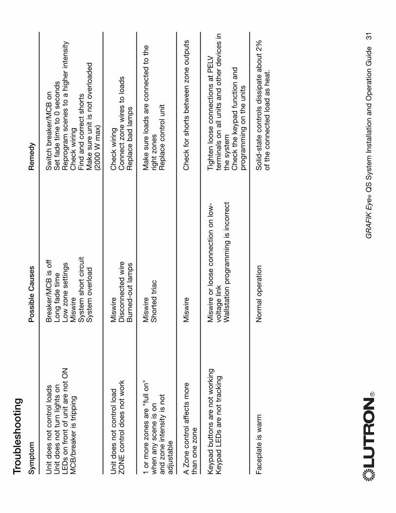
Sym
pto
m
Uni
t d
oes
not
cont
rol l
oad
sU
nit
doe
s no
t tu
rn li
ghts
on
LED
s on
fro
nt o
f un
it ar
e no
t O
NM
CB
/bre
aker
is t
ripp
ing
Uni
t d
oes
not
cont
rol l
oad
ZO
NE
con
trol
doe
s no
t w
ork
1 or
mor
e zo
nes
are
"ful
l on"
whe
n an
y sc
ene
is o
nan
d z
one
inte
nsity
is n
otad
just
able
A Z
one
cont
rol a
ffect
s m
ore
than
one
zon
e
Key
pad
but
tons
are
not
wor
king
Key
pad
LE
Ds
are
not
trac
king
Face
pla
te is
war
m
Po
ssib
le C
ause
s
Bre
aker
/MC
B is
off
Long
fad
e tim
eLo
w z
one
sett
ings
Mis
wire
Sys
tem
sho
rt c
ircui
tS
yste
m o
verlo
ad
Mis
wire
Dis
conn
ecte
d w
ireB
urne
d-o
ut la
mp
s
Mis
wire
Sho
rted
tria
c
Mis
wire
Mis
wire
or
loos
e co
nnec
tion
on lo
w-
volta
ge li
nkW
alls
tatio
n p
rogr
amm
ing
is in
corr
ect
Nor
mal
op
erat
ion
Rem
edy
Sw
itch
bre
aker
/MC
B o
nS
et f
ade
time
to 0
sec
ond
sR
epro
gram
sce
nes
to a
hig
her
inte
nsity
Che
ck w
iring
Find
and
cor
rect
sho
rts
Mak
e su
re u
nit
is n
ot o
verlo
aded
(2
000
W m
ax)
Che
ck w
iring
Con
nect
zon
e w
ires
to lo
ads
Rep
lace
bad
lam
ps
Mak
e su
re lo
ads
are
conn
ecte
d t
o th
erig
ht z
ones
Rep
lace
con
trol
uni
t
Che
ck f
or s
hort
s b
etw
een
zone
out
put
s
Tigh
ten
loos
e co
nnec
tions
at
PE
LVte
rmin
als
on a
ll un
its a
nd o
ther
dev
ices
inth
e sy
stem
Che
ck t
he k
eyp
ad f
unct
ion
and
pro
gram
min
g on
the
uni
ts
Sol
id-s
tate
con
trol
s d
issi
pat
e ab
out
2%of
the
con
nect
ed lo
ad a
s he
at.
RG
RA
FIK
Eye
®Q
SS
yste
m In
stal
latio
n an
d O
per
atio
n G
uid
e
31
Tro
uble
sho
otin
g
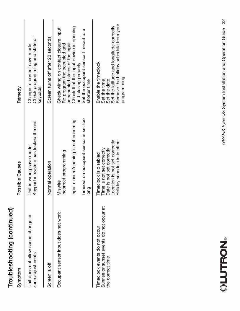
RG
RA
FIK
Eye
®Q
SS
yste
m In
stal
latio
n an
d O
per
atio
n G
uid
e
32
Sym
pto
m
Uni
t d
oes
not
allo
w s
cene
cha
nge
orzo
ne a
dju
stm
ents
Scr
een
is o
ff
Occ
upan
t se
nsor
inp
ut d
oes
not
wor
k
Tim
eclo
ck e
vent
s d
o no
t oc
cur
Sun
rise
or s
unse
t ev
ents
do
not
occu
r at
the
corr
ect
time
Po
ssib
le C
ause
s
Uni
t in
wro
ng s
ave
mod
eK
eyp
ad in
sys
tem
has
lock
ed t
he u
nit
Nor
mal
op
erat
ion
Mis
wire
Inco
rrec
t p
rogr
amm
ing
Inp
ut c
losu
re/o
pen
ing
is n
ot o
ccur
ring
Tim
eout
on
occu
pan
t se
nsor
is s
et t
oolo
ng
Tim
eclo
ck is
dis
able
dTi
me
is n
ot s
et c
orre
ctly
Dat
e is
not
set
cor
rect
lyLo
catio
n is
not
set
cor
rect
lyH
olid
ay s
ched
ule
is in
effe
ct
Rem
edy
Cha
nge
to c
orre
ct s
ave
mod
eC
heck
pro
gram
min
g an
d s
tate
of
keyp
ads
Scr
een
turn
s of
f af
ter
20 s
econ
ds
Che
ck w
iring
on
cont
act
clos
ure
inp
utR
e-p
rogr
am t
he o
ccup
ied
and
unoc
cup
ied
sta
tes
of t
he in
put
Che
ck t
hat
the
inp
ut d
evic
e is
op
enin
gan
d c
losi
ng p
rop
erly
Set
the
occ
upan
t se
nsor
tim
eout
to
ash
orte
r tim
e
Ena
ble
the
tim
eclo
ckS
et t
he t
ime
Set
the
dat
eS
et t
he la
titud
e an
d lo
ngitu
de
corr
ectly
Rem
ove
the
holid
ay s
ched
ule
from
you
rp
rogr
amm
ing
Tro
uble
sho
otin
g (c
ont
inue
d)

RG
RA
FIK
Eye
®Q
SS
yste
m In
stal
latio
n an
d O
per
atio
n G
uid
e
33
Sym
pto
m
ED
U (e
lect
roni
c d
rive
unit
of t
he w
ind
owtr
eatm
ent)
will
not
mov
e
ED
U(e
lect
roni
c d
rive
unit
of t
he w
ind
owtr
eatm
ent)
doe
s no
t fu
lly o
pen
or
fully
clos
e
Win
dow
tre
atm
ent
mov
es in
the
op
pos
ited
irect
ion
whe
n ra
ise/
low
er b
utto
ns a
rep
ushe
d
Key
pad
LE
Ds
are
off
and
key
pad
will
not
cont
rol a
ny w
ind
ow t
reat
men
t
Key
pad
LE
Ds
are
on b
ut k
eyp
ad w
ill n
otco
ntro
l any
win
dow
tre
atm
ent
Key
pad
doe
s no
t op
erat
e al
l the
win
dow
trea
tmen
ts it
is a
ssig
ned
to
Win
dow
tre
atm
ents
in a
roo
m m
ove
onth
eir
own
Po
ssib
le C
ause
s
ED
U is
not
pow
ered
Win
dow
tre
atm
ent
fab
ric is
cau
ght
onso
met
hing
ED
U is
not
ass
igne
d t
o a
keyp
ad
Pre
sets
hav
e b
een
set
inco
rrec
tlyLi
mits
hav
e b
een
set
inco
rrec
tlyW
ind
ow t
reat
men
t fa
bric
is c
augh
t on
som
ethi
ng
Op
en a
nd c
lose
lim
its h
ave
bee
n re
vers
ed
No
pow
er is
goi
ng t
o ke
ypad
All
pre
sets
are
set
to
the
sam
e he
ight
Com
mun
icat
ions
link
is n
ot w
ired
to
the
ED
UE
DU
has
bee
n un
assi
gned
fro
m k
eyp
ad
ED
Uha
s b
een
unas
sign
ed f
rom
key
pad
All
pre
sets
are
set
to
the
sam
e he
ight
ED
U is
not
wire
d c
orre
ctly
Key
pad
is n
ot w
ired
cor
rect
ly
ED
Us
are
assi
gned
to
a ke
ypad
inan
othe
r ro
om
Rem
edy
Che
ck E
DU
pow
erC
heck
and
unb
ind
win
dow
tre
atm
ent
fab
ricA
ssig
n th
e E
DU
to
a ke
ypad
Try
usin
g ra
ise/
low
er b
utto
ns o
n ke
ypad
Set
lim
its c
orre
ctly
Che
ck a
nd u
nbin
d w
ind
ow t
reat
men
tfa
bric
Set
lim
its c
orre
ctly
Che
ck a
nd w
ire p
ower
to
keyp
ad
Try
usin
g ra
ise/
low
er b
utto
ns o
n ke
ypad
Che
ck a
nd w
ire t
he E
DU
link
Rea
ssig
n th
e E
DU
to
the
keyp
ad
Rea
ssig
n th
e E
DU
to
the
keyp
adTr
y us
ing
rais
e/lo
wer
but
tons
on
keyp
adC
heck
and
rew
ire E
DU
Che
ck a
nd r
ewire
key
pad
Rea
ssig
n th
e E
DU
to
the
corr
ect
keyp
ad
Tro
uble
sho
otin
g (c
ont
inue
d) -
Win
do
w T
reat
men
t F
unct
ions
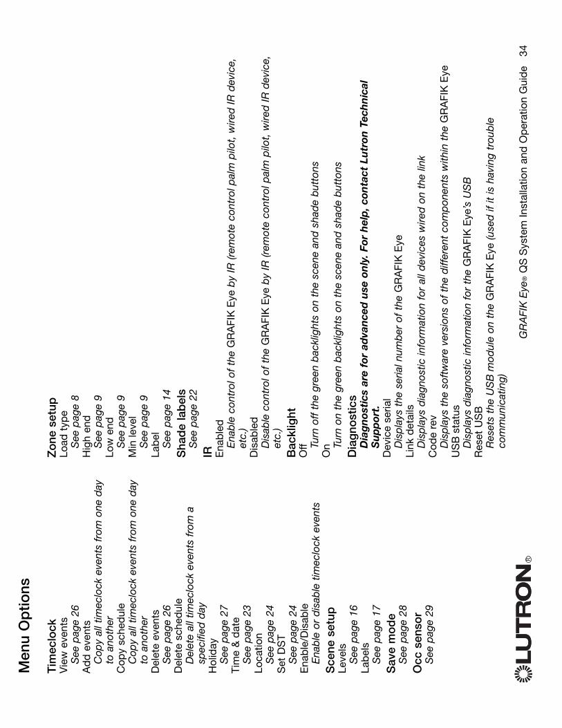
Men
u O
ptio
ns
Tim
eclo
ckV
iew
eve
nts
See
pag
e 26
Ad
d e
vent
sC
opy
all t
imec
lock
eve
nts
from
one
day
to a
noth
erC
opy
sche
dul
eC
opy
all t
imec
lock
eve
nts
from
one
day
to a
noth
erD
elet
e ev
ents
See
pag
e 26
Del
ete
sche
dul
eD
elet
e al
l tim
eclo
ck e
vent
s fr
om a
spec
ified
day
Hol
iday
See
pag
e 27
Tim
e &
dat
eS
ee p
age
23Lo
catio
nS
ee p
age
24S
et D
ST
See
pag
e 24
Ena
ble
/Dis
able
Ena
ble
or
dis
able
tim
eclo
ck e
vent
sS
cene
set
upLe
vels
See
pag
e 16
Lab
els
See
pag
e 17
Sav
e m
od
eS
ee p
age
28O
cc s
enso
rS
ee p
age
29
RG
RA
FIK
Eye
®Q
SS
yste
m In
stal
latio
n an
d O
per
atio
n G
uid
e
34
Zo
ne s
etup
Load
typ
eS
ee p
age
8H
igh
end
See
pag
e 9
Low
end
See
pag
e 9
Min
leve
lS
ee p
age
9La
bel
See
pag
e 14
Sha
de
lab
els
See
pag
e 22
IR Ena
ble
dE
nab
le c
ontr
ol o
f th
e G
RA
FIK
Eye
by
IR (r
emot
e co
ntro
l pal
m p
ilot,
wire
d IR
dev
ice,
etc.
)D
isab
led
Dis
able
con
trol
of
the
GR
AFI
KE
yeb
y IR
(rem
ote
cont
rol p
alm
pilo
t, w
ired
IR d
evic
e,et
c.)
Bac
klig
htO
ff Turn
off
the
gre
en b
ackl
ight
s on
the
sce
ne a
nd s
had
e b
utto
nsO
n Turn
on
the
gree
n b
ackl
ight
s on
the
sce
ne a
nd s
had
e b
utto
nsD
iag
nost
ics
Dia
gn
osti
cs a
re f
or a
dva
nce
d u
se o
nly
. For
hel
p, c
onta
ct L
utr
on T
ech
nic
alS
up
por
t.D
evic
e se
rial
Dis
pla
ys t
he s
eria
l num
ber
of
the
GR
AFI
KE
yeLi
nk d
etai
lsD
isp
lays
dia
gnos
tic in
form
atio
n fo
r al
l dev
ices
wire
d o
n th
e lin
kC
ode
rev
Dis
pla
ys t
he s
oftw
are
vers
ions
of
the
diff
eren
t co
mp
onen
ts w
ithin
the
GR
AFI
KE
yeU
SB
stat
usD
isp
lays
dia
gnos
tic in
form
atio
n fo
r th
e G
RA
FIK
Eye
’s U
SB
Res
et U
SB
Res
ets
the
US
Bm
odul
e on
the
GR
AFI
KE
ye (u
sed
if it
is h
avin
g tr
oub
leco
mm
unic
atin
g)
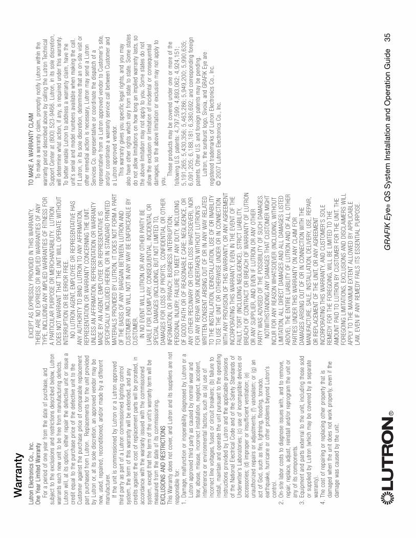
RG
RA
FIK
Eye
®Q
SS
yste
m In
stal
latio
n an
d O
per
atio
n G
uid
e
35
Lutro
nEl
ectro
nics
Co.,
Inc.
One
Year
Lim
ited
War
rant
yFo
r a
perio
d of
one
yea
r fro
m t
he d
ate
of p
urch
ase,
and
subj
ect
to t
he e
xclu
sion
s an
d re
stric
tions
des
crib
ed b
elow
,Lut
ron
war
rant
s ea
ch n
ew u
nit
to b
e fre
e fro
m m
anuf
actu
ring
defe
cts.
Lutro
n w
ill,a
t its
opt
ion,
eith
er r
epai
r th
e de
fect
ive
unit
or is
sue
acr
edit
equa
l to
the
purc
hase
pric
e of
the
def
ectiv
e un
it to
the
Cust
omer
aga
inst
the
pur
chas
e pr
ice
of c
ompa
rabl
e re
plac
emen
tpa
rt pu
rcha
sed
from
Lut
ron.
Repl
acem
ents
for
the
uni
t pr
ovid
edby
Lut
ron
or,a
t its
sol
e di
scre
tion,
an a
ppro
ved
vend
or m
ay b
ene
w,us
ed,r
epai
red,
reco
nditi
oned
,and
/or
mad
e by
a d
iffer
ent
man
ufac
ture
r.If
the
unit
is c
omm
issi
oned
by
Lutro
n or
a L
utro
n ap
prov
edth
ird p
arty
as
part
of a
Lut
ron
com
mis
sion
ed li
ghtin
g co
ntro
lsy
stem
,the
ter
m o
f th
is w
arra
nty
will
be
exte
nded
,and
any
cred
its a
gain
st t
he c
ost
of r
epla
cem
ent
parts
will
be
pror
ated
,in
acco
rdan
ce w
ith t
he w
arra
nty
issu
ed w
ith t
he c
omm
issi
oned
syst
em,e
xcep
t th
at t
he t
erm
of
the
unit'
s w
arra
nty
term
will
be
mea
sure
d fro
m t
he d
ate
of it
s co
mm
issi
onin
g.EX
CLUS
ION
SAN
DRE
STRI
CTIO
NS
This
War
rant
y do
es n
ot c
over
,and
Lut
ron
and
its s
uppl
iers
are
not
resp
onsi
ble
for:
1.D
amag
e,m
alfu
nctio
n or
inop
erab
ility
dia
gnos
ed b
y Lu
tron
or a
Lutro
n ap
prov
ed t
hird
par
ty a
s ca
used
by
norm
al w
ear
and
tear
,abu
se,m
isus
e,in
corr
ect
inst
alla
tion,
negl
ect,
acci
dent
,in
terfe
renc
e or
env
ironm
enta
l fac
tors
,suc
h as
(a)
use
of
inco
rrec
t lin
e vo
ltage
s,fu
ses
or c
ircui
t br
eake
rs;(
b) f
ailu
re t
oin
stal
l,m
aint
ain
and
oper
ate
the
unit
purs
uant
to
the
oper
atin
gin
stru
ctio
ns p
rovi
ded
by L
utro
n an
d th
e ap
plic
able
pro
visi
ons
of t
he N
atio
nal E
lect
rical
Cod
e an
d of
the
Saf
ety
Stan
dard
s of
Unde
rwrit
er's
Lab
orat
orie
s;(c
) us
e of
inco
mpa
tible
dev
ices
or
acce
ssor
ies;
(d)
impr
oper
or
insu
ffici
ent
vent
ilatio
n;(e
)un
auth
oriz
ed r
epai
rs o
r ad
just
men
ts;(
f) va
ndal
ism
;or
(g)
anac
t of
God
,suc
h as
fire
,lig
htni
ng,f
lood
ing,
torn
ado,
earth
quak
e,hu
rric
ane
or o
ther
pro
blem
s be
yond
Lut
ron'
sco
ntro
l.2.
On-
site
labo
r co
sts
to d
iagn
ose
issu
es w
ith,a
nd t
o re
mov
e,re
pair,
repl
ace,
adju
st,r
eins
tall
and/
or r
epro
gram
the
uni
t or
any
of it
s co
mpo
nent
s.3.
Equi
pmen
t an
d pa
rts e
xter
nal t
o th
e un
it,in
clud
ing
thos
e so
ldor
sup
plie
d by
Lut
ron
(whi
ch m
ay b
e co
vere
d by
a s
epar
ate
war
rant
y).
4.Th
e co
st o
f re
pairi
ng o
r re
plac
ing
othe
r pr
oper
ty t
hat
isda
mag
ed w
hen
the
unit
does
not
wor
k pr
oper
ly,ev
en if
the
dam
age
was
cau
sed
by t
he u
nit.
EXCE
PT A
S EX
PRES
SLY
PRO
VID
ED IN
TH
IS W
ARRA
NTY
,TH
ERE
ARE
NO
EXP
RESS
OR
IMPL
IED
WAR
RAN
TIES
OF
ANY
TYPE
,IN
CLUD
ING
AN
Y IM
PLIE
D W
ARRA
NTI
ES O
F FI
TNES
S FO
RA
PART
ICUL
AR P
URPO
SE O
R M
ERCH
ANTA
BILI
TY.
LUTR
ON
DO
ES N
OT
WAR
RAN
T TH
AT T
HE
UNIT
WIL
L O
PERA
TE W
ITH
OUT
INTE
RRUP
TIO
N O
R BE
ERR
OR
FREE
.N
O L
UTRO
N A
GEN
T,EM
PLO
YEE
OR
REPR
ESEN
TATI
VE H
ASAN
Y AU
THO
RITY
TO
BIN
D L
UTRO
N T
O A
NY
AFFI
RMAT
ION,
REPR
ESEN
TATI
ON
OR
WAR
RAN
TY C
ON
CERN
ING
TH
E UN
IT.
UNLE
SS A
N A
FFIR
MAT
ION,
REPR
ESEN
TATI
ON
OR
WAR
RAN
TYM
ADE
BY A
N A
GEN
T,EM
PLO
YEE
OR
REPR
ESEN
TATI
VE IS
SPEC
IFIC
ALLY
INCL
UDED
HER
EIN,
OR
IN S
TAN
DAR
D P
RIN
TED
MAT
ERIA
LS P
ROVI
DED
BY
LUTR
ON,
IT D
OES
NO
T FO
RM A
PAR
TO
F TH
E BA
SIS
OF
ANY
BARG
AIN
BET
WEE
N L
UTRO
N A
ND
CUST
OM
ER A
ND
WIL
L N
OT
IN A
NY
WAY
BE
ENFO
RCEA
BLE
BYCU
STO
MER
.IN
NO
EVE
NT
WIL
L LU
TRO
N O
R AN
Y O
THER
PAR
TY B
ELI
ABLE
FO
R EX
EMPL
ARY,
CON
SEQ
UEN
TIAL
,IN
CID
ENTA
L O
RSP
ECIA
L D
AMAG
ES (
INCL
UDIN
G,BU
T N
OT
LIM
ITED
TO,
DAM
AGES
FO
R LO
SS O
F PR
OFI
TS,
CON
FID
ENTI
AL O
R O
THER
INFO
RMAT
ION,
OR
PRIV
ACY;
BUSI
NES
S IN
TERR
UPTI
ON
;PE
RSO
NAL
INJU
RY;F
AILU
RE T
O M
EET
ANY
DUT
Y,IN
CLUD
ING
OF
GO
OD
FAI
TH O
R O
F RE
ASO
NAB
LE C
ARE;
NEG
LIG
ENCE
,OR
ANY
OTH
ER P
ECUN
IARY
OR
OTH
ER L
OSS
WH
ATSO
EVER
),N
OR
FOR
ANY
REPA
IR W
ORK
UN
DER
TAKE
N W
ITH
OUT
LUT
RON
'SW
RITT
EN C
ON
SEN
T AR
ISIN
G O
UT O
F O
R IN
AN
Y W
AY R
ELAT
EDTO
TH
E IN
STAL
LATI
ON,
DEI
NST
ALLA
TIO
N,US
E O
F O
R IN
ABIL
ITY
TO U
SE T
HE
UNIT
OR
OTH
ERW
ISE
UND
ER O
R IN
CO
NN
ECTI
ON
WIT
H A
NY
PRO
VISI
ON
OF
THIS
WAR
RAN
TY,O
R AN
Y AG
REEM
ENT
INCO
RPO
RATI
NG
TH
IS W
ARRA
NTY
,EVE
N IN
TH
E EV
ENT
OF
THE
FAUL
T,TO
RT (
INCL
UDIN
G N
EGLI
GEN
CE),
STRI
CT L
IABI
LITY
,BR
EACH
OF
CON
TRAC
T O
R BR
EACH
OF
WAR
RAN
TY O
F LU
TRO
NO
R AN
Y SU
PPLI
ER,A
ND
EVE
N IF
LUT
RON
OR
ANY
OTH
ERPA
RTY
WAS
AD
VISE
D O
F TH
E PO
SSIB
ILIT
Y O
F SU
CH D
AMAG
ES.
NO
TWIT
HST
AND
ING
AN
Y D
AMAG
ES T
HAT
CUS
TOM
ER M
IGH
TIN
CUR
FOR
ANY
REAS
ON
WH
ATSO
EVER
(IN
CLUD
ING,
WIT
HO
UTLI
MIT
ATIO
N,AL
L D
IREC
T D
AMAG
ES A
ND
ALL
DAM
AGES
LIS
TED
ABO
VE),
THE
ENTI
RE L
IABI
LITY
OF
LUTR
ON
AN
D O
F AL
L O
THER
PART
IES
UND
ER T
HIS
WAR
RAN
TY O
N A
NY
CLAI
M F
OR
DAM
AGES
ARI
SIN
G O
UT O
F O
R IN
CO
NN
ECTI
ON
WIT
H T
HE
MAN
UFAC
TURE
,SAL
E,IN
STAL
LATI
ON,
DEL
IVER
Y,US
E,RE
PAIR
,O
R RE
PLAC
EMEN
T O
F TH
E UN
IT,O
R AN
Y AG
REEM
ENT
INCO
RPO
RATI
NG
TH
IS W
ARRA
NTY
,AN
D C
USTO
MER
'S S
OLE
REM
EDY
FOR
THE
FORE
GO
ING,
WIL
L BE
LIM
ITED
TO
TH
EAM
OUN
T PA
ID T
O L
UTRO
N B
Y CU
STO
MER
FO
R TH
E UN
IT.T
HE
FORE
GO
ING
LIM
ITAT
ION
S,EX
CLUS
ION
S AN
D D
ISCL
AIM
ERS
WIL
LAP
PLY
TO T
HE
MAX
IMUM
EXT
ENT
ALLO
WED
BY
APPL
ICAB
LELA
W,E
VEN
IF A
NY
REM
EDY
FAIL
S IT
S ES
SEN
TIAL
PUR
POSE
.
TOM
AKE
AW
ARRA
NTY
CLAI
MTo
mak
e a
war
rant
y cl
aim
,pro
mpt
ly n
otify
Lut
ron
with
in t
hew
arra
nty
perio
d de
scrib
ed a
bove
by
calli
ng t
he L
utro
n Te
chni
cal
Supp
ort
Cent
er a
t (8
00)
523-
9466
.Lut
ron,
in it
s so
le d
iscr
etio
n,w
ill d
eter
min
e w
hat
actio
n,if
any,
is r
equi
red
unde
r th
is w
arra
nty.
To b
ette
r en
able
Lut
ron
to a
ddre
ss a
war
rant
y cl
aim
,hav
e th
eun
it's
seria
l and
mod
el n
umbe
rs a
vaila
ble
whe
n m
akin
g th
e ca
ll.If
Lutro
n,in
its
sole
dis
cret
ion,
dete
rmin
es t
hat
an o
n-si
te v
isit
orot
her
rem
edia
l act
ion
is n
eces
sary
,Lut
ron
may
sen
d a
Lutro
nSe
rvic
es C
o.re
pres
enta
tive
or c
oord
inat
e th
e di
spat
ch o
f a
repr
esen
tativ
e fro
m a
Lut
ron
appr
oved
ven
dor
to C
usto
mer
's s
ite,
and/
or c
oord
inat
e a
war
rant
y se
rvic
e ca
ll be
twee
n Cu
stom
er a
nda
Lutro
n ap
prov
ed v
endo
r.Th
is w
arra
nty
give
s yo
u sp
ecifi
c le
gal r
ight
s,an
d yo
u m
ayal
so h
ave
othe
r rig
hts
whi
ch v
ary
from
sta
te t
o st
ate.
Som
e st
ates
do n
ot a
llow
lim
itatio
ns o
n ho
w lo
ng a
n im
plie
d w
arra
nty
last
s,so
the
abov
e lim
itatio
n m
ay n
ot a
pply
to
you.
Som
e st
ates
do
not
allo
w t
he e
xclu
sion
or
limita
tion
of in
cide
ntal
or
cons
eque
ntia
lda
mag
es,s
o th
e ab
ove
limita
tion
or e
xclu
sion
may
not
app
ly t
oyo
u.Th
ese
prod
ucts
may
be
cove
red
unde
r on
e or
mor
e of
the
follo
win
g U.
S.pa
tent
s:4,
797,
599;
4,89
3,06
2;4,
924,
151;
5,19
1,26
5;5,
430,
356;
5,46
3,28
6;5,
949,
200;
5,99
0,63
5;6,
091,
205;
6,18
8,18
1;6,
380,
692;
and
corr
espo
ndin
g fo
reig
npa
tent
s.O
ther
U.S
.and
for
eign
pat
ents
may
be
pend
ing.
Lutro
n,th
e su
nbur
st lo
go,S
ivoi
a,an
d G
RAFI
KEy
e ar
ere
gist
ered
tra
dem
arks
of
Lutro
n El
ectro
nics
Co.
,Inc
.©
200
7 Lu
tron
Elec
troni
cs C
o.,I
nc.
War
rant
y

Inte
rnet
: w
ww
.lutr
on.c
omE
-mai
l: p
rod
uct@
lutr
on.c
om
WO
RLD
HE
AD
QU
AR
TE
RS
US
ALu
tron
Ele
ctro
nics
Co.
, Inc
.72
00 S
uter
Roa
d, C
oope
rsbu
rg, P
A 1
8036
-129
9TE
L +1
.610
.282
.380
0FA
X +
1.61
0.28
2.12
43To
ll-Fr
ee 1
.888
.LU
TRO
n1Te
chni
cal S
uppo
rt 1
.800
.523
.946
6
Bra
zil
Lutr
on B
Zdo
Bra
sil L
tda.
AV, B
rasi
l, 23
9, J
ardi
m A
mer
ica
Sao
Pau
lo-S
P, C
EP
: 014
31-0
00, B
razi
lTE
L +5
5.11
.388
5.51
52FA
X +
55.1
1.38
87.7
138
Nor
th a
nd S
outh
Am
eric
a Te
chni
cal H
otlin
esU
SA
, Can
ada,
Car
ibbe
an:1
.800
.523
.946
6M
exic
o:+1
.888
.235
.291
0C
entr
al/S
outh
Am
eric
a:+1
.610
.282
.670
1
EU
RO
PE
AN
HE
AD
QU
AR
TE
RS
Uni
ted
Kin
gdom
Lutr
on E
A L
td.
6 S
over
eign
Clo
se, L
ondo
n, E
1W 3
JF U
nite
d K
ingd
omTE
L +4
4.(0
)20.
7702
.065
7FA
X +
44.(0
)20.
7480
.689
9FR
EE
PH
ON
E (U
K) 0
800.
282.
107
Tech
nica
l sup
port
+44
.(0)2
0.76
80.4
481
Fran
ceLu
tron
LTC
, S.A
.R.L
.90
rue
de
Vill
iers
, 923
00 L
eval
lois
-Per
ret F
ranc
eTE
L +3
3.(0
)1.4
1.05
.42.
80FA
X +
33.(0
)1.4
1.05
.01.
80FR
EE
PH
ON
E 0
800.
90.1
2.18
Ger
man
yLu
tron
Ele
ctro
nics
Gm
bH, L
ands
berg
er A
llee
201,
130
55B
erlin
, Ger
man
yTE
L +4
9.(0
)30.
9710
.459
0FA
X +
49.(0
)30.
9710
.459
1FR
EE
PH
ON
E 0
0800
.588
7.66
35
Ital
yLu
tron
LD
V, S
.r.l.
FRE
EP
HO
NE
800
.979
.208
Spa
in, B
arce
lona
Lutr
on C
C, S
.R.L
.G
ran
Via
del
Car
los
III, 8
4, p
lant
a 3a
, 08
028,
Bar
celo
na, S
pain
TEL
+34.
93.4
96.5
7.42
FAX
+34
.93.
496.
57.0
1FR
EE
PH
ON
E 0
900.
948.
944
Spa
in, M
adri
dLu
tron
CC
, S.R
.L.
Cal
le O
rens
e, 8
5, 2
8020
Mad
rid, S
pain
TEL
+34.
91.5
67.8
4.79
FAX
+34
.91.
567.
84.7
8FR
EE
PH
ON
E 0
900.
948.
944
AS
IAN
HE
AD
QU
AR
TE
RS
Sin
gapo
reLu
tron
GL
Ltd.
15
Hoe
Chi
ang
Roa
d, #
07-0
3 E
uro
Asi
a C
entr
e,S
inga
pore
089
316
TEL
+65.
6220
.466
6FA
X +
65.6
220.
4333
Chi
na, B
eijin
gLu
tron
GL
Ltd.
Bei
jing
Rep
rese
ntat
ive
Offi
ce5t
h Fl
oor,
Chi
na L
ife T
ower
N
o. 1
6 C
haow
ai S
tree
t, C
haoy
ang
Dis
tric
t, B
eijin
g10
0020
Chi
naTE
L +8
6.10
.587
7.18
17FA
X +
86.1
0.58
77.1
816
Chi
na, S
hang
hai
Lutr
on G
L Lt
d., S
hang
hai R
epre
sent
ativ
e O
ffice
S
uite
07,
39t
h Fl
oor,
Pla
za 6
612
66 N
an J
ing
Wes
t R
oad,
Sha
ngha
i, 20
0040
Chi
naTE
L +8
6.21
.628
8.14
73FA
X +
86.2
1.62
88.1
751
Chi
na, H
ong
Kon
gLu
tron
GL
Ltd.
Uni
t 280
8, 2
8/F,
248
Que
en's
Roa
d E
ast
Wan
chai
, Hon
g K
ong
TEL
+852
.210
4.77
33FA
X +
852.
2104
.763
3
Japa
nLu
tron
Asu
ka C
o. L
td.
No.
16
Kow
a B
uild
ing,
4F,
1-9
-20
Aka
saka
, Min
ato-
ku, T
okyo
107
-005
2 Ja
pan
TEL
+81.
3.55
75.8
411
FAX
+81
.3.5
575.
8420
FRE
EP
HO
NE
012
0.08
3.41
7
Asi
a Te
chni
cal H
otlin
esN
orth
ern
Chi
na:1
0.80
0.71
2.15
36S
outh
ern
Chi
na:1
0.80
0.12
0.15
36H
ong
Kon
g:80
0.90
1.84
9In
done
sia:
001.
803.
011.
3994
Japa
n: +
81.3
.557
5.84
11M
acau
:080
0.40
1S
inga
pore
:800
.120
.449
1Ta
iwan
:00.
801.
137.
737
Thai
land
:001
.800
.120
.665
853
Oth
er c
ount
ries:
+65.
6220
.466
6
Co
ntac
t In
form
atio
n
R
Lutr
on E
lect
roni
cs C
o., I
nc.
Mad
e an
d p
rinte
d in
U.S
.A. 0
9/07
P/N
032
-172
Rev
. A

WallstationInstallation Guide
Please ReadLow-Voltage PELV (Class 2: USA)
24 V 30 mA� QSWS2-1B
� QSWS2-2B
� QSWS2-3B
� QSWS2-5B
� QSWS2-7B
� QSWS2-2BRL
� QSWS2-3BRL
� QSWS2-5BRL
� QSWS2-2BRLIR
� QSWS2-3BRLIR
� QSWS2-5BRLIR
� QSWS2-1RLD
� QSWS2-2RLD
� QSWS2-3BD
R
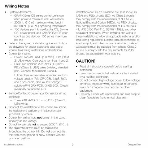
Wallstation circuits are classified as Class 2 circuits
(USA) and PELV circuits (IEC). As Class 2 circuits,
they comply with the requirements of NFPA® 70,
National Electrical Code® (NEC®). As PELV circuits,
they comply with the requirements of IEC 60364-4-
41, VDE 0100 Part 410, BS7671:1992, and other
equivalent standards. When installing and wiring to
these wallstations, follow all applicable national and/or
local wiring regulations. External circuits connected to
input, output, and other communication terminals of
wallstations must be supplied from a listed Class 2
source or comply with the requirements for PELV
circuits, as applicable in your country.
CAUTION!• Read all instructions carefully before starting
installation.
• Lutron recommends that wallstations be installed
by a qualified electrician.
• Do not connect high-voltage power to low-voltage
terminals. Improper wiring can result in personal
injury or damage to the control or to other
equipment.
• Use only a cloth with warm water and mild soap to
clean faceplates (no chemical cleaners).
Wiring Notes• System Maximums
— GRAFIK Eye® QS series control units can
each power a maximum of 3 wallstations.
— 2000 ft. (610 m) maximum wiring length
— 32-104 °F (0-40 °C) operating temperature.
— 100 devices per link (seeTouch® QS, Sivoia®
QS, power panel, and GRAFIK Eye QS each
count as one device); 100 zones maximum
per link
• Refer to the system installation guide and Lutron
job drawings for power cable and data cable
(control link) wiring restrictions and limitations.
• Control Link Wiring
— Power: Two #18 AWG (1.0 mm2) PELV (Class
2: USA) wires. Connect to terminals 1 and 2.
— Data: Two shielded #22 AWG (1.0 mm2)
PELV (Class 2: USA) wires (twisted, shielded
pair). Connect to terminals 3 and 4.
Lutron offers a one-cable, non-plenum, low-
voltage solution (P/N GRX-CBL-346S-500),
and a one-cable, plenum, low-voltage
solution (P/N GRX-PCBL-346S-500). Check
availability outside the U.S.
• Sensor/Contact Closure Input Connector Wiring
(optional):
— Three #18 AWG (1.0 mm2) PELV (Class 2:
USA) wires.
• Connect the wallstation to the control link inside
the wallstation’s wallbox or in a junction box
(provided by others).
• Control link wiring must not be run in the same
raceway as line voltage.
• Control link wiring is not to exceed 2000 ft. (610 m).
• The drain/shield wire must be maintained
throughout the control link. Do not connect the
shield to earth/ground or allow contact with the
grounded wallbox.
Installation Instructions Occupant Copy2
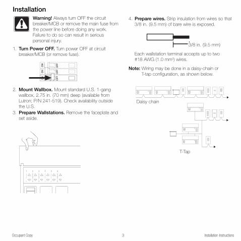
Occupant Copy Installation Instructions3
InstallationWarning! Always turn OFF the circuit
breaker/MCB or remove the main fuse from
the power line before doing any work.
Failure to do so can result in serious
personal injury.
1. Turn Power OFF. Turn power OFF at circuit
breaker/MCB (or remove fuse).
2. Mount Wallbox. Mount standard U.S. 1-gang
wallbox, 2.75 in. (70 mm) deep (available from
Lutron; P/N 241-519). Check availability outside
the U.S.
3. Prepare Wallstations. Remove the faceplate and
set aside.
ON
OF
F
ON
OF
F
ON
OF
F
1 2 3 4 5 6
4. Prepare wires. Strip insulation from wires so that
3/8 in. (9.5 mm) of bare wire is exposed.
Each wallstation terminal accepts up to two
#18 AWG (1.0 mm2) wires.
Note: Wiring may be done in a daisy-chain or
T-tap configuration, as shown below.
3/8 in. (9.5 mm)
LUTRON
LUTRON
LUTRON
LUTRONLUTRON
LUTRON
LUTRON
LUTRON
LUTRON
LUTRON
LUTRON LUTRON LUTRON
LUTRON
Daisy chain
T-Tap

Installation Instructions Occupant Copy4
5. Connect the Wallstation to the Control Link.Connect two #22 (1.0 mm2) shielded, twisted pair wires
to terminals 3 and 4 of the wallstation’s control link
connector. Shielding (drain) of the twisted pair wires
must be connected together as shown, but do notconnect the shielding to earth/ground or the wallstation
or allow contact with the grounded wallbox.
Note: Use the wire connector required by local code
(those shown are common in the US).
4
3
2
1
C
B
A
Drain
Data link: (1) twisted,shielded pair #22 AWG (1.0 mm2)3: MUX
4: MUX
2 #18 AWG(1.0 mm2)
2 #18 AWG(1.0 mm2)
PELV (Class 2: USA)control wiring(2) #18 AWG (1.0 mm2)1: Common2: 24 V
Control Link Wiring
ACN
099 9
42 9
CO
OP
ER
SB
UR
G, P
A 1
8036
US
A:
30 m
A
6. Connect the Wallstation to external contactclosure inputs (optional). If using one contact
closure input, connect the input to terminal A of
the wallstation sensor/contact closure input
connector. If using two contact closure inputs,
connect the inputs to terminals A and B. Connect
the common side of the contact closure inputs to
terminal C.
Contact Closure Input Wiring
Notes for Contact Closure Inputs:
Verify compatibility of external contact closure input
devices. The contact closure inputs can be used
with either dry contact closures or ground-
referenced solid-state outputs. The outputs must
stay in the closed or open states for at least 40
msec in order to be recognized by the wallstation.
If there is any question as to whether the device is
compatible with these specifications, contact the
manufacturer.
Contact closure input function is determined by
the programming of the top and bottom buttons of
the wallstation.
Input 2
Common
(3) #18 AWG
(1.0 mm2)
Input 1
ACN
099 9

Occupant Copy Installation Instructions5
Typical Mounting Diagram(Exploded View)
7. Mount Wallstation. Carefully mount and align the
wallstation as shown. Screw top and bottom
screw into the control and wallbox. Replace
faceplate, adapter (for insert versions), and button
assembly.
8. Turn Power ON. Turn ON control breaker, or
replace main fuse.
Notes• Unprogrammed (out of the box) QS wallstations
and control units will all work together until they are
reprogrammed otherwise.
• LEDs on wallstation buttons light when the scene
programmed to it is the last scene activated.
Wallbox
Control
Mounting screws
Buttons
Adapter
Faceplate
Adapter screws

2. Select wallstation function (optional).The info screen on the GRAFIK Eye QS control
unit will display a prompt to change your
wallstation’s function (type).
Press the OK button on the QS control unit to
display the current wallstation function/type. To
change, use the master buttons to scroll through
the available choices until the function you want
displays on the info screen.
The keypad menu will display only functions that
are available for the wallstation model that is
“talking” to it. The example shown here is for a 5-
button wallstation with raise/lower buttons.
Press the OK button to accept and save your
highlighted choice.
6Installation Instructions Occupant Copy
System CommunicationsIn order for wallstations to communicate with a
control unit, each wallstation must be individually
configured to “talk” to a “listening” control unit.
In order for shade wallstations to control
exclusively a given group of window treatments
(as opposed to all window treatments in the
system), each shade wallstation must be
individually configured to “talk” to its respective
window treatments.
(Only one wallstation can be in setup mode at a
time.)
1. Enter Setup Mode. Press and hold simultaneously
for 3 seconds the top and bottom buttons (not
including raise/lower buttons) on the wallstation. For
1-button wallstations, press and hold the single
button for 10 seconds. (LEDs will flash periodically.)
Note: For wallstations with two sets of
buttons, you will program each
set as if each were its own
wallstation. For multigroup shade
wallstations, first select the group,
then program the wallstation for
that group.
Press and hold the top and bottom buttons on your
wallstation for 3 seconds to enter setup mode.
OK
KeypadChange type?
Press OK Master
buttons
OK
button
OK
Change type?
01-04, off Master
buttons
OK
button

3b.For wallstations with partition function:
2-button wallstations that control one partition:
The LEDs on the wallstation will alternately blink.
On each GRAFIK Eye QS control unit within the
partitioned space, press and hold the top button
on the lighting column until its LEDs flash in
unison. The control units will then function together
when the partition is open.
All other partition wallstations: On the wallstation,
press the button you want to use to control
partition function. Its LED will blink slowly. Then, on
each GRAFIK Eye QS control unit that is related to
that partitioned space, press and hold the top
button on the lighting column until its LEDs flash in
unison.
For multiple partitions, repeat for additional buttons
on the partition wallstation, and the related control
units.
NNoottee:: To stop a control unit from “listening” to a
wallstation, put the wallstation in setup mode,
then press and hold for 3 seconds the bboottttoomm
button on the lighting keypad of the control unit
you want to stop listening.
Proceed to Step 4.
7Occupant Copy Installation Instructions
ProgrammingThe next step is to configure your wallstationwhich GRAFIK Eye QS control unit or windowtreatment “listens” when the wallstation“talks”, depending on your wallstation’sfunction. You will perform only one of Steps 3athrough 3e for each wallstation.
3a.For wallstations with scene, panic, orsequence functions: Press and hold the top
button on the GRAFIK Eye QS control unit lighting
column until its LEDs flash in unison. Repeat for
each control unit you want to “listen” to the
wallstation for the selected function.
NNoottee:: To stop a control unit from “listening” to a
wallstation, put the wallstation in setup mode,
and press and hold for 3 seconds the bboottttoomm
button on the lighting keypad of the control unit
you want to stop listening.
Proceed to Step 4.
OK
1 2 3 4 5 6
Press and hold the top button on the lighting column
for 3 seconds to make control unit “listen”.
OK
1 2 3 4 5 6
Press and hold the top button on the lighting column
for 3 seconds to make control unit “listen”.
OK
1 2 3 4 5 6
Press and hold
for 3 seconds to
make control unit
stop “listening”.

8Installation Instructions Occupant Copy
3c. For wallstations with fine tune function: On the
GRAFIK Eye QS control unit, press simultaneously the
raise and lower buttons for the zone you want the
wallstation to fine tune. Repeat for each zone you wish
to “listen” to the selected wallstation, or for zones on
additional control units. When listening, zone LEDs
flash. When unassigned (not “listening”), the 3 middle
zone LEDs light.
NNoottee:: To stop a zone from listening to a wallstation, put
the wallstation in setup mode, and press
simultaneously the raise and lower buttons on the
zone you want to stop listening.
Proceed to Step 4.
3d.For wallstations with zone function: On the
wallstation, press the button you want to program
to toggle (alternate between) zones. Its LED will
blink slowly.
On the GRAFIK Eye QS control unit, for the zone
you want to “listen” to the wallstation, use the raise and
lower buttons to set the desired levels. The LEDs will
indicate the level. Then, press simultaneously those
raise and lower buttons to listen that zone to the
wallstation. When listening, zone LEDs flash. When not
listening (unassigned), the 3 middle zone LEDs light.
Repeat for each zone you wish to assign to the
selected wallstation, or for zones on additional
control units.
Finally, repeat to program the remaining buttons
on the wallstation with their respective zones.
NNoottee:: To stop a zone from listening to a wallstation, put
the wallstation in setup mode, and press
simultaneously the raise and lower buttons on the
zone you want to stop listening.
Proceed to Step 4.
3e.For wallstations configured for shadefunction:
Note: Entering setup mode will cause the window
treatments to move between their open and
close limits. Be sure that the open and close
limits have been set correctly (see page 12).
Because your wallstation is configured for shade
function, upon entering setup mode, EDUs
(electronic drive units of window treatments)
assigned to that wallstation will move to their close
limit, and EDUs not assigned to it will move to their
open limit.
To assign an EDU to the wallstation that is in setup
mode, use one of the following methods:
Either -Press the top button on the wallstation. Each
time you press the top button, a different EDU
that is assigned to that wallstation will open
and close in an 8-inch range. Press the top
button until the EDU you wish to assign to the
wallstation moves. (You can also use the
bottom button, which moves through the
EDUs in the opposite order.)
Assign or unassign the currently selected EDU
to the wallstation using the raise and lower
buttons:
The lower button assigns the selected EDU.
The raise button unassigns the selected EDU.
OK
1 2 3 4 5 6
Press and hold the raise and lower
buttons for the zone you want to
listen or stop listening.
Lower button
(assign)
Raise button
(unasssign)
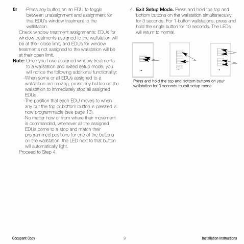
9Occupant Copy Installation Instructions
Or -Press any button on an EDU to toggle
between unassignment and assignment for
that EDU’s window treatment to the
wallstation.
Check window treatment assignments: EDUs for
window treatments assigned to the wallstation will
be at their close limit, and EDUs for window
treatments not assigned to the wallstation will be
at their open limit.
Note: Once you have assigned window treatments
to a wallstation and exited setup mode, you
will notice the following additional functionality:
-When some or all EDUs assigned to a
wallstation are moving, press any button on the
wallstation to immediately stop all assigned
EDUs.
-The position that each EDU moves to when
any but the top or bottom button is pressed is
now programmable (see page 13).
-No matter how or from where their movement
is commanded, whenever all the assigned
EDUs come to a stop and match their
programmed positions for one of the buttons
on the wallstation, the LED next to that button
will automatically light.
Proceed to Step 4.
4. Exit Setup Mode. Press and hold the top and
bottom buttons on the wallstation simultaneously
for 3 seconds. For 1-button wallstations, press and
hold the single button for 10 seconds. The LEDs
will return to normal.
Press and hold the top and bottom buttons on your
wallstation for 3 seconds to exit setup mode.
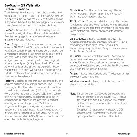
10Installation Instructions Occupant Copy
SeeTouch® QS Wallstation Button Functions The following functions are menu choices when the
wallstation is in setup mode and the GRAFIK Eye QS
is displaying the keypad menu. Each function choice
is explained below. See the next page for a summary
table of wallstations and their function choices.
SScceenneess:: Choose from the list of preset groups of
scenes to assign to the buttons on this wallstation.
See the next page for a list of available scene
groupings for each keypad.
ZZoonnee:: Assigns control of one or more zones on one
or more GRAFIK Eye QS control units to the selected
wallstation button. Pressing a zone control button on
a wallstation causes all assigned zones to go to the
set level, with a fade time of 3 seconds (if all
assigned zones are currently off). If any assigned
zone is currently on (at any level), the LED for that
zone will be lit, and pressing the wallstation button
that controls that zone will cause all assigned zones
to fade to off over 3 seconds. The 3-second fade
time cannot be adjusted.
PPaarrttiittiioonn:: Used for rooms that can be divided by one
or more partitions into smaller spaces. The LED on
the assigned button indicates whether the partition
should be considered open (LED is lit; control units
work together as one) or closed (LED is off; control
units work independently in separate spaces). A
contact closure will open the partition; a contact
opening will close the partition. Wallstations
programmed for partitioning are only used for
partitioning, and each button is configured to control
different combinations of control units. When the
partition between two GRAFIK Eye QS control units is
open, the control units act together.
22BB PPaarrttiittiioonn:: 2-button wallstations only. The top
button indicates partition open, and the bottom
button indicates partition closed.
22BB FFiinnee TTuunnee:: 2-button wallstations only. The buttons
function as raise and lower buttons for the assigned
zones. Zones are assigned by pressing the raise and
lower buttons simultaneously; repeat to change
assignments.
22BB SSeeqquueennccee:: 2-button wallstations only. This
function scrolls through scenes 5 through 16 using
their assigned fade rates, then repeats. For
showroom-type applications. Program as you would
for the Scene function.
22BB PPaanniicc:: 2-button wallstations only. Pressing the
button sends all assigned zones immediately to
scene 16, and locks out all button presses on all
connected wallstations and control units. Program as
you would for the Scene function.
TTooggggllee:: 1-button wallstations only. The button toggles
between scene 1 and off.
WWiinnddooww ttrreeaattmmeennttss:: Assign control of a group of
shades to a wallstation.
NNoottee:: If a control unit has devices connected to it
through contact closure inputs, CCI1 follows
the top button and CCI2 follows the bottom
button. The contact closure is equivalent to a
button press.
Exception: On a 2-button wallstation, CCI1
closure action follows the top button and
opening action follows the bottom button.
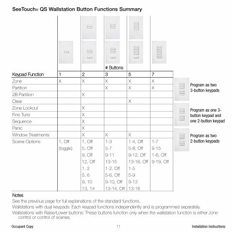
11Occupant Copy Installation Instructions
## BBuuttttoonnss
KKeeyyppaadd FFuunnccttiioonn 11 22 33 55 77
Zone X X X X X
Partition X X X
2B Partition X
Clear X
Zone Lockout X
Fine Tune X
Sequence X
Panic X
Window Treatments X X X
Scene Options 1, Off 1, Off 1-3 1-4, Off 1-7
(toggle) 5, Off 5-7 5-8, Off 9-15
9, Off 9-11 9-12, Off 1-6, Off
12, Off 13-15 13-16, Off 9-19, Off
1, 2 1-2, Off 1-5
5, 6 5-6, Off 5-9
9, 10 9-10, Off 9-13
13, 14 13-14, Off 13-16
NNootteess
See the previous page for full explanations of the standard functions.
Wallstations with dual keypads: Each keypad functions independently and is programmed separately.
Wallstations with Raise/Lower buttons: These buttons function only when the wallstation function is either zonecontrol or control of scenes.
SeeTouch® QS Wallstation Button Functions Summary
Program as two 3-button keypads
Program as one 3-button keypad andone 2-button keypad
Program as two 2-button keypads

12Installation Instructions Occupant Copy
Adjusting Window TreatmentSettingsSetting LimitsNote: Entering Limit Setup mode may cause window
treatments to move approximately 8 inches up
or down. Be sure that each window treatment
is positioned so that the fabric can safely
move 8 inches up or down before entering
Limit Setup mode.
To be able to adjust window treatment limits,
your wallstation must have raise and lower
buttons. If your model does not have these,
please contact Lutron Technical Support or
refer to your window treatment documentation
to use the buttons on your EDU to manually
set limits.
1. On your shade keypad, press and
hold the top and raise buttons
simultaneously for 3 seconds. The
LEDs next to the top and bottom
buttons will cycle.
Note: At any time while in Limit Setup mode, you
can move all window treatments together to
their current open limit by slowly double-
pressing the top button, or to their current
close limit by slowly double-tapping the
bottom button.
Note: Once EDUs (electronic drive units of the
window treatment) have been assigned to
shade keypads, limits can be set for an EDU
only using the shade keypad it is assigned to,
and a shade keypad can set limits only for
those EDUs assigned to it.
2. Select the EDU you want to to adjust using the top
button on the shade keypad. Each time you press
the top button, a different EDU that is assigned to
that shade keypad will open and close in an 8-
inch range to indicate it is selected. Press the top
button until the EDU for the window treatment you
wish to adjust moves. (You can also use the
bottom button, which moves through the assigned
EDUs in the opposite order.)
3. Adjust the currently selected EDU
to the desired level for the open
limit (the maximum the window
treatment is allowed to open)
using the raise and lower buttons.
4. Press and hold the top button on the shade
keypad simultaneously for 3 seconds to store the
current position as the open limit. The LED next to
the top button will flash quickly for 2 seconds.
5. Adjust the currently selected EDU to the desired
level for the close limit (the maximum the window
treatment is allowed to close) using the raise and
lower buttons.
6. Press and hold the bottom button on the shade
keypad for 3 seconds to store the current position
as the close limit. The LED next to the bottom
button will flash quickly for 2 seconds.
7. Repeat steps 2 through 6 to set the open and
close limits for each window treatment assigned to
the shade keypad.
8. Press and hold the top and raise buttons on the
shade keypad simultaneously for 3 seconds to exit
Limit Setup mode.

13Occupant Copy Installation Instructions
Preset Adjustment: Simple MethodNote: The top button will always open the shades
fully, and the bottom button will always close
the shades fully. Only the shade presets
activated by the intermediate buttons can be
reprogrammed.
1. Use the raise and lower buttons on
the shade keypad to set all EDUs
(electronic drive units of the
window treatments) to the desired
preset levels.
2. Press and hold the respective preset
button on the shade keypad for 3
seconds to save the EDU preset
positions. The LED next to the
button will flash and then light
continuously, indicating the preset
has been stored.
Note: Once EDU presets have been assigned to
buttons on a shade keypad, those presets are
accessible for an EDU only using the shade
keypad it is assigned to, and a shade keypad
can access preset levels only for those EDUs
assigned to it.
Preset Adjustment: Advanced MethodNote: The advanced method for adjusting presets is
needed only if you wish to have the window
treatments assigned to the shade keypad set
at different positions in the preset. If, however,
you wish all the window treatments in the
group to be lined up with one another in the
preset, you should use the Simple Method
above.
Note: Entering Assignment mode will cause the
window treatments to move between their
open and close limits. Be sure that the open
and close limits have been set correctly.
1. On the shade keypad whose preset
you wish to adjust, press and hold the
top and bottom buttons simultaneously
for 3 seconds. The LEDs next to the
buttons will flash. EDUs (electronic
drive units) for the assigned window
treatments will move to their closed
limits, and EDUs for unassigned
window treatments will move to their
open limits.
2. Press the preset button you wish to adjust on that
shade keypad. The adjacent LED will blink rapidly.
EDUs for assigned window treatments will
automatically move to their current preset settings.
3. Use the raise and lower buttons
to move all EDUs for assigned
window treatments together to the
desired preset setting.
4. To move an EDU individually to its desired preset
setting, select the EDU using the top button on
the shade keypad. Each time you press the top
button, a different EDU that is assigned to that
shade keypad will open and close in an 8-inch
range. Press repeatedly until the EDU for the
window treatment you wish to adjust moves.
Adjust that EDU to the desired height using the
raise and lower buttons.
Repeat this step for all assigned EDUs you wish to
adjust.
5. Once you are satisfied that all the assigned EDUs
are set to the positions you want to assign as the
preset, press and hold the respective preset
button on the shade keypad for 3 seconds. The
preset will be saved.
6. Press and hold the top and bottom buttons on the
shade keypad simultaneously for 3 seconds to exit
to normal mode. The LEDs next to the buttons will
stop flashing.
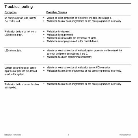
Installation Instructions Occupant Copy14
Symptom Possible Causes
Troubleshooting
No communication with GRAFIKEye control unit.
Wallstation buttons do not work;LEDs do not track.
LEDs do not light.
Contact closure inputs or sensorinput do not produce the desiredresult in the system.
• Miswire or loose connection at the control link data lines 3 and 4.• Wallstation has not been programmed or has been programmed incorrectly.
• Wallstation is miswired.• Wallstation is not powered.• Wallstation is not wired to the correct set of lights.• Wallstation is not programmed to the correct device.
• Miswire or loose connection at wallstation(s) or processor on the control linkcommon and power connections 1 and 2.
• Wallstation has been programmed incorrectly.
• Miswire or loose connection at wallstation sensor/CCI connector.• Wallstation has not been programmed or has been programmed incorrectly.
Wallstation buttons do not functionas intended.
• Wallstation has not been programmed or has been programmed incorrectly.

Occupant Copy Installation Instructions15
Troubleshooting: Window Treatment FunctionsSymptom
EDU (electronic drive unit of thewindow treatment) will not move
EDU (electronic drive unit of the windowtreatment) does not fully open or fullyclose
Window treatment moves in theopposite direction when raise/lowerbuttons are pushed
Keypad LEDs are off and keypad willnot control any window treatment
Keypad LEDs are on but keypad will notcontrol any window treatment
Keypad does not operate all thewindow treatments it is assigned to
Window treatments in a room move ontheir own
Possible Causes
EDU is not poweredWindow treatment fabric is caught onsomethingEDU is not assigned to a keypad
Presets have been set incorrectlyLimits have been set incorrectlyWindow treatment fabric is caught onsomething
Open and close limits have beenreversed
No power is going to keypad
All presets are set to the same heightCommunications link is not wired to theEDUEDU has been unassigned from keypadOpen and close limits are the same
EDU has been unassigned from keypadAll presets are set to the same heightEDU is not wired correctlyKeypad is not wired correctly
EDUs are assigned to a keypad inanother room
Remedy
Check EDU powerCheck and unbind window treatmentfabricAssign the EDU to a keypad
Try using raise/lower buttons on keypadSet limits correctlyCheck and unbind window treatmentfabric
Set limits correctly
Check and wire power to keypad
Try using raise/lower buttons on keypadCheck and wire the EDU link
Reassign the EDU to the keypadSet limits correctly
Reassign the EDU to the keypadTry using raise/lower buttons on keypadCheck and rewire EDUCheck and rewire keypad
Reassign the EDU to the correct keypad

R
Lutron Electronics Co., Inc.Made and printed in U.S.A.P/N 030-939 Rev. A 10/07
Contact InformationWarrantyLLuuttrroonn EElleeccttrroonniiccss CCoo..,, IInncc..OOnnee YYeeaarr LLiimmiitteedd WWaarrrraannttyy
For a period of one year from the date of purchase, and subject tothe exclusions and restrictions described below, Lutron warrants eachnew unit to be free from manufacturing defects. Lutron will, at its option,either repair the defective unit or issue a credit equal to the purchaseprice of the defective unit to the Customer against the purchase price ofcomparable replacement part purchased from Lutron. Replacementsfor the unit provided by Lutron or, at its sole discretion, an approvedvendor may be new, used, repaired, reconditioned, and/or made by adifferent manufacturer.
If the unit is commissioned by Lutron or a Lutron approved third partyas part of a Lutron commissioned lighting control system, the term ofthis warranty will be extended, and any credits against the cost ofreplacement parts will be prorated, in accordance with the warrantyissued with the commissioned system, except that the term of the unit'swarranty term will be measured from the date of its commissioning.EEXXCCLLUUSSIIOONNSS AANNDD RREESSTTRRIICCTTIIOONNSS This Warranty does not cover, and Lutron and its suppliers are notresponsible for:1. Damage, malfunction or inoperability diagnosed by Lutron or a Lutron
approved third party as caused by normal wear and tear, abuse,misuse, incorrect installation, neglect, accident, interference orenvironmental factors, such as (a) use of incorrect line voltages, fusesor circuit breakers; (b) failure to install, maintain and operate the unitpursuant to the operating instructions provided by Lutron and theapplicable provisions of the National Electrical Code and of the SafetyStandards of Underwriter's Laboratories; (c) use of incompatibledevices or accessories; (d) improper or insufficient ventilation; (e)unauthorized repairs or adjustments; (f) vandalism; or (g) an act ofGod, such as fire, lightning, flooding, tornado, earthquake, hurricane orother problems beyond Lutron's control.
2. On-site labor costs to diagnose issues with, and to remove, repair,replace, adjust, reinstall and/or reprogram the unit or any of itscomponents.
3.Equipment and parts external to the unit, including those sold orsupplied by Lutron (which may be covered by a separate warranty).
4. The cost of repairing or replacing other property that is damagedwhen the unit does not work properly, even if the damage wascaused by the unit.EXCEPT AS EXPRESSLY PROVIDED IN THIS WARRANTY, THERE
ARE NO EXPRESS OR IMPLIED WARRANTIES OF ANY TYPE,INCLUDING ANY IMPLIED WARRANTIES OF FITNESS FOR APARTICULAR PURPOSE OR MERCHANTABILITY. LUTRON DOESNOT WARRANT THAT THE UNIT WILL OPERATE WITHOUTINTERRUPTION OR BE ERROR FREE.
NO LUTRON AGENT, EMPLOYEE OR REPRESENTATIVE HAS ANYAUTHORITY TO BIND LUTRON TO ANY AFFIRMATION,REPRESENTATION OR WARRANTY CONCERNING THE UNIT.UNLESS AN AFFIRMATION, REPRESENTATION OR WARRANTY MADEBY AN AGENT, EMPLOYEE OR REPRESENTATIVE IS SPECIFICALLYINCLUDED HEREIN, OR IN STANDARD PRINTED MATERIALSPROVIDED BY LUTRON, IT DOES NOT FORM A PART OF THE BASISOF ANY BARGAIN BETWEEN LUTRON AND CUSTOMER AND WILLNOT IN ANY WAY BE ENFORCEABLE BY CUSTOMER.
IN NO EVENT WILL LUTRON OR ANY OTHER PARTY BE LIABLEFOR EXEMPLARY, CONSEQUENTIAL, INCIDENTAL OR SPECIALDAMAGES (INCLUDING, BUT NOT LIMITED TO, DAMAGES FOR LOSSOF PROFITS, CONFIDENTIAL OR OTHER INFORMATION, ORPRIVACY; BUSINESS INTERRUPTION; PERSONAL INJURY; FAILURE
TO MEET ANY DUTY, INCLUDING OF GOOD FAITH OR OFREASONABLE CARE; NEGLIGENCE, OR ANY OTHER PECUNIARY OROTHER LOSS WHATSOEVER), NOR FOR ANY REPAIR WORKUNDERTAKEN WITHOUT LUTRON'S WRITTEN CONSENT ARISINGOUT OF OR IN ANY WAY RELATED TO THE INSTALLATION,DEINSTALLATION, USE OF OR INABILITY TO USE THE UNIT OROTHERWISE UNDER OR IN CONNECTION WITH ANY PROVISION OFTHIS WARRANTY, OR ANY AGREEMENT INCORPORATING THISWARRANTY, EVEN IN THE EVENT OF THE FAULT, TORT (INCLUDINGNEGLIGENCE), STRICT LIABILITY, BREACH OF CONTRACT ORBREACH OF WARRANTY OF LUTRON OR ANY SUPPLIER, AND EVENIF LUTRON OR ANY OTHER PARTY WAS ADVISED OF THEPOSSIBILITY OF SUCH DAMAGES.
NOTWITHSTANDING ANY DAMAGES THAT CUSTOMER MIGHTINCUR FOR ANY REASON WHATSOEVER (INCLUDING, WITHOUTLIMITATION, ALL DIRECT DAMAGES AND ALL DAMAGES LISTEDABOVE), THE ENTIRE LIABILITY OF LUTRON AND OF ALL OTHERPARTIES UNDER THIS WARRANTY ON ANY CLAIM FOR DAMAGESARISING OUT OF OR IN CONNECTION WITH THE MANUFACTURE,SALE, INSTALLATION, DELIVERY, USE, REPAIR, OR REPLACEMENTOF THE UNIT, OR ANY AGREEMENT INCORPORATING THISWARRANTY, AND CUSTOMER'S SOLE REMEDY FOR THEFOREGOING, WILL BE LIMITED TO THE AMOUNT PAID TO LUTRONBY CUSTOMER FOR THE UNIT. THE FOREGOING LIMITATIONS,EXCLUSIONS AND DISCLAIMERS WILL APPLY TO THE MAXIMUMEXTENT ALLOWED BY APPLICABLE LAW, EVEN IF ANY REMEDYFAILS ITS ESSENTIAL PURPOSE.TTOO MMAAKKEE AA WWAARRRRAANNTTYY CCLLAAIIMM
To make a warranty claim, promptly notify Lutron within the warrantyperiod described above by calling the Lutron Technical Support Centerat (800) 523-9466. Lutron, in its sole discretion, will determine whataction, if any, is required under this warranty. To better enable Lutron toaddress a warranty claim, have the unit's serial and model numbersavailable when making the call. If Lutron, in its sole discretion,determines that an on-site visit or other remedial action is necessary,Lutron may send a Lutron Services Co. representative or coordinate thedispatch of a representative from a Lutron approved vendor toCustomer's site, and/or coordinate a warranty service call betweenCustomer and a Lutron approved vendor.
This warranty gives you specific legal rights, and you may also haveother rights which vary from state to state. Some states do not allowlimitations on how long an implied warranty lasts, so the above limitationmay not apply to you. Some states do not allow the exclusion orlimitation of incidental or consequential damages, so the above limitationor exclusion may not apply to you.
These products may be covered under one or more of the followingU.S. patents: D461,782; and corresponding foreign patents. Other U.S.and foreign patents may be pending.
National Electric Code, NEC, and NFPA are registered trademarks ofthe National Fire Protection Association, Inc., Quincy, Massachusetts.
Lutron, the sunburst logo, Sivoia, seeTouch, and GRAFIK Eye areregistered trademarks of Lutron Electronics Co., Inc.© 2007 Lutron Electronics Co., Inc.
Internet: www.lutron.comE-mail: [email protected]
WORLD HEADQUARTERSUSALutron Electronics Co., Inc.7200 Suter Road, Coopersburg, PA 18036-1299
TEL +1.610.282.3800FAX +1.610.282.1243Toll-Free 1.888.LUTRON1Technical Support 1.800.523.9466North and South America Technical Hotlines
USA, Canada, Caribbean: 1.800.523.9466Mexico: +1.888.235.2910Central/South America: +1.610.282.6701EUROPEAN HEADQUARTERSUnited KingdomLutron EA Ltd.6 Sovereign Close, London,E1W 3JF United Kingdom
TEL +44.(0)20.7702.0657FAX +44.(0)20.7480.6899FREEPHONE (UK) 0800.282.107Technical support +44.(0)20.7680.4481ASIAN HEADQUARTERSSingaporeLutron GL Ltd.15 Hoe Chiang Road,#07-03 Euro Asia Centre, Singapore 089316
TEL +65.6220.4666FAX +65.6220.4333Asia Technical HotlinesNorthern China: 10.800.712.1536Southern China: 10.800.120.1536Hong Kong: 800.901.849Indonesia: 001.803.011.3994Japan: +81.3.5575.8411Macau: 0800.401Singapore: 800.120.4491Taiwan: 00.801.137.737Thailand: 001.800.120.665853Other countries: +65.6220.4666

GRX-CI-NWK-E, GRX-CI-RS232, GRX-IA-CI-NWK-E, GRX-IA-CI-RS232, OMX-CI-NWK-E, OMX-CI-RS232, GRX-CI-PRG, GRX-IA-CI-PRG, and QSE-CI-NWK-E Interface Controls
PELV (Class 2: USA) Devices 12 - 24 V 200 mA
R
English
Esp
añol
Fran
çaisPortu
guês
Ned
erlands
Deu
tschItalian
o
Mounting
1. Mount the Control Interface directly on a wall, as shownin the Mounting Diagram, using screws (not included).When mounting, provide sufficient space for connectingcables.The unit can also be placed in the LUT-19AV-1U AVrack using the screws provided with the unit. The LUT-19AV-1U will hold up to four units.If conduit is desired for wiring, the LUT-5x10-ENC canbe used to mount one unit.
2. Strip 3/8 in. (10 mm) of insulation from wires. EachData Link terminal will accept up to two #18 AWG (1.0 mm2) wires.
3. Connect wiring as shown in the Wiring Diagram (nextpage). LED 1 lights continuously (Power) and LED 7blinks rapidly (Data Link RX) when the Class 2 (PELV)Data Link is installed correctly.
Control Interface
Wall
LUT-19AV-1U
Wire Strip Length
3/8 in. (10 mm)
Mounting Diagram
Please refer to the enclosed CD for the productSpecification Sheets and Operation Manuals, EthernetDevice IP program, and RS232 Protocol information.
GRAFIK SystemsInstallation InstructionsOccupant Copy Please Read
Dimensions2.50 in.
(63.5 mm)
3.75 in.(95.3 mm)
4.26 in.(108.2 mm)
5.26 in.(133.6 mm)
1.06 in.(26.9 mm)
MountingHoles
LUT-5x10-ENC

ZONE 6ZONE 4
HOT/LIVESSA
CU WIRE ONLY
ZONE 2ZONE 3ZONE 5
NEUTRAL
ZONE 1
CLASS 21 2 3 4
USAClass 2IECPELV
4 3 2 1
2 GRAFIK Eye® and GRAFIK Systems Installation Instructions
Low-Voltage PELV (Class 2: USA) Wiring
Important Notes
• Install in accordance with all applicable regulations.• CAUTION: Do not connect line voltage/mains power to device. Improper wiring can result in personal injury or
damage to the device or to other equipment.• This control can use PELV (Class 2: USA) wiring methods. Check with your local electrical inspector for
compliance with national and local codes and wiring practices.• Make daisy-chain connections to the low-voltage PELV (Class 2: USA) Data Link terminals on the end of the
Control Interface. • Do not use T-taps. Run all wires in and out of the terminal block.• Each terminal accepts up to two #18 AWG (1.0 mm2) wires.
R
To additional Wallstations/Control Interfaces (16 maximum; 3 powered from one GRAFIK
Eye Control Unit without external 12 Vpower supply; PRG and NWK-E modelscount as two devices toward the maximumof three connected to one GRAFIK Eye
3000 control unit when not using optionaltransformer)
Control Interface Wiring:
GRX-3000 Control Unit
Rear View of GRAFIK Eye Control Unit (GRX-3106 shown)
Use Lutron Cable GRX-CBL-346S
or equivalent
(RS232 model shown)
Data Link
Data Link:4: MUX3: MUX
One shielded, twistedpair #18 AWG
(1.0 mm2)for data link
(terminals 3 and 4)
PELV (Class 2: USA) Power wiring:2: Power1: Common
Two #18 AWG (1.0 mm2) conductorsfor Common (terminal 1) and 12 V (terminal 2)
4 3 2 1
Data Link: (1) shielded, twistedpair #18 AWG (1.0 mm2)
4: MUX3: MUX
Class 2/PELVPower wiring:1: Common2: 24 V Power(2) #18 AWG (1.0 mm2) pigtails, 6 in. (152 mm) maximum length
D: Drain/Shield
(2) #12 AWG (2.5 mm2)
(2) #12 AWG (2.5 mm2)
(NWK-E model shown)
Control Interface Wiring:GRX-4000 Control Unit, OMX Control Station Device Link, or QS Link(Data Link connection shown)
Note: #12 AWG (2.5 mm2)conductors for Common (terminal 1)and 24 V Power (terminal 2) willnot fit in terminals; use #18 AWG(1.0 mm2) pigtails (< 6 in./152 mm).
Note: Do not connect Drain/Shield toGround (Earth) or Wallstation/ControlInterfaces. Connect the bare drainwires and cut off the outside shield.
Use Lutron Cable GRX-CBL-46L

A/V Connections and Signal/Link Information
R GRAFIK Eye® and GRAFIK Systems Installation Instructions 3
GRX-CI-NWK-E, GRX-IA-CI-NWK-E, OMX-CI-NWK-E
RJ45 jack:Ethernet Link
Ethernet link (on)Ethernet activity(flashing)
Ethernet speed (10: off; 100: on)
Data Link (toControl Units,processors,andwallstations)
DIP Switches LED 1: PowerLED 2: Ethernet linkLED 3, 4, 5: UnusedLED 6: Data link TXLED 7: Data link RX
LED 1: PowerLED 2, 3: UnusedLED 4: RS232 link TXLED 5: RS232 link RXLED 6: Data link TXLED 7: Data link RX
CAT5 Cable: maximum 328 ft.
(100 m)
RS232 Cable: maximum 50 ft.
(15 m)
To PC or AV Equipment. For Ethernet Link, use CAT5 cableto connect to auxiliary equipment. The Ethernet Link LEDwill light continuously when link is present and will flashwhen there is link activity. Additional Ethernet networkequipment and cables provided by others.
12-24 V to outlet (with optional transformer).Do not wire terminal 2 on Data Link when usingoptional transformer. To power separately fromthe Data Link, order the following Lutrontransformer model numbers:
120 V : T120-15DC-9-BL240 V : TE240-15DC-9-BL240 V (UK): TU240-15DC-9-BL
GRX-CI-RS232, GRX-IA-CI-RS232, OMX-CI-RS232
GRX-CI-PRG, GRX-IA-CI-PRG, QSE-CI-NWK-E
Data Link (toControl Units,processors, andwallstations)
RS232Link
COM
TxD
RxD
RS232 Pin Connect WiringTypical PC or Pin on
RS232 Interface A/V equipment 9-pin cableCommon Com 5Receive TxD 3Transmit RxD 2
Links and connections are same as shown forabove units.
LED 1: PowerLED 2: Ethernet linkLED 3: UnusedLED 4: RS232 link TX
LED 5: RS232 link RXLED 6: Data link TXLED 7: Data link RX
To PC or AV equipment:Use a standard DB9serial cable, or followthe chart at right.
DIP Switches
1 2 3 4 5 6 7
1 2 3 4 5 6 7
1 2 3 4 5 6 7
Lutron Electronics Co., Inc.Made and printed in U.S.A. 1/08P/N 040-242 Rev. AR
Internet: www.lutron.comE-mail: [email protected] HeadquartersUSALutron Electronics Co., Inc.7200 Suter Road, Coopersburg, PA18036-1299TEL +1.610.282.3800FAX +1.610.282.1243Toll-Free 1.888.LUTRON1Technical Support 1.800.523.9466BrazilLutron BZ do Brasil Ltda.AV, Brasil, 239, Jardim AmericaSao Paulo-SP, CEP: 01431-000,BrazilTEL +55.11.3885.5152FAX +55.11.3887.7138North and South America Technical HotlinesUSA, Canada, Caribbean:1.800.523.9466Mexico: +1.888.235.2910Central/South America:+1.610.282.6701European HeadquartersUnited KingdomLutron EA Ltd.6 Sovereign Close, London, E1W 3JFUnited KingdomTEL +44.(0)20.7702.0657FAX +44.(0)20.7480.6899FREEPHONE (UK) 0800.282.107Technical support+44.(0)20.7680.4481FranceLutron LTC, S.A.R.L.90 rue de Villiers, 92300 Levallois-Perret FranceTEL +33.(0)1.41.05.42.80FAX +33.(0)1.41.05.01.80FREEPHONE 0800.90.12.18GermanyLutron Electronics GmbH,Landsberger Allee 201, 13055 Berlin, GermanyTEL +49.(0)30.9710.4590FAX +49.(0)30.9710.4591FREEPHONE 00800.5887.6635ItalyLutron LDV, S.r.l.FREEPHONE 800.979.208Spain, BarcelonaLutron CC, S.R.L.Gran Via del Carlos III, 84, planta 3a, 08028, Barcelona, SpainTEL +34.93.496.57.42FAX +34.93.496.57.01FREEPHONE 0900.948.944Spain, MadridLutron CC, S.R.L.Calle Orense, 85, 28020 Madrid, SpainTEL +34.91.567.84.79FAX +34.91.567.84.78FREEPHONE 0900.948.944
Asian HeadquartersSingaporeLutron GL Ltd. 15 Hoe Chiang Road, #07-03 EuroAsia Centre, Singapore 089316TEL +65.6220.4666FAX +65.6220.4333China, BeijingLutron GL Ltd. Beijing Representative Office5th Floor, China Life Tower No. 16 Chaowai Street, ChaoyangDistrict, Beijing 100020 ChinaTEL +86.10.5877.1817FAX +86.10.5877.1816China, GuangzhouLutron GL Ltd. GuangzhouRepresentative OfficeSuite A09, 23/F Tower A, Centre Plaza161 Lin He Xi Lu, Tian He District,Guangzhou 510620 ChinaTEL +86.20.2885.8266FAX +86.20.2885.8366China, ShanghaiLutron GL Ltd., ShanghaiRepresentative Office Suite 07, 39th Floor, Plaza 661266 Nan Jing West Road, Shanghai, 200040 ChinaTEL +86.21.6288.1473FAX +86.21.6288.1751China, Hong KongLutron GL Ltd.Unit 2808, 28/F, 248 Queen’s Road EastWanchai, Hong KongTEL +852.2104.7733FAX +852.2104.7633JapanLutron Asuka Co. Ltd.No. 16 Kowa Building, 4F, 1-9-20Akasaka, Minato-ku, Tokyo 107-0052 JapanTEL +81.3.5575.8411FAX +81.3.5575.8420FREEPHONE 0120.083.417Asia Technical HotlinesNorthern China: 10.800.712.1536Southern China: 10.800.120.1536Hong Kong: 800.901.849Indonesia: 001.803.011.3994Japan: +81.3.5575.8411Macau: 0800.401Singapore: 800.120.4491Taiwan: 00.801.137.737Thailand: 001.800.120.665853Other countries: +65.6220.4666
Lutron Electronics Co., Inc.One Year Limited Warranty
For a period of one year from the date of purchase, and subject to the exclusions and restrictions describedbelow, Lutron warrants each new unit to be free from manufacturing defects. Lutron will, at its option, either repairthe defective unit or issue a credit equal to the purchase price of the defective unit to the Customer against thepurchase price of comparable replacement part purchased from Lutron. Replacements for the unit provided byLutron or, at its sole discretion, an approved vendor may be new, used, repaired, reconditioned, and/or made by adifferent manufacturer.
If the unit is commissioned by Lutron or a Lutron approved third party as part of a Lutron commissionedlighting control system, the term of this warranty will be extended, and any credits against the cost of replacementparts will be prorated, in accordance with the warranty issued with the commissioned system, except that the termof the unit’s warranty term will be measured from the date of its commissioning.EXCLUSIONS AND RESTRICTIONSThis Warranty does not cover, and Lutron and its suppliers are not responsible for:1. Damage, malfunction or inoperability diagnosed by Lutron or a Lutron approved third party as caused bynormal wear and tear, abuse, misuse, incorrect installation, neglect, accident, interference or environmental factors,such as (a) use of incorrect line voltages, fuses or circuit breakers; (b) failure to install, maintain and operate the unitpursuant to the operating instructions provided by Lutron and the applicable provisions of the National ElectricalCode and of the Safety Standards of Underwriter’s Laboratories; (c) use of incompatible devices or accessories; (d)improper or insufficient ventilation; (e) unauthorized repairs or adjustments; (f) vandalism; or (g) an act of God, suchas fire, lightning, flooding, tornado, earthquake, hurricane or other problems beyond Lutron’s control.2. On-site labor costs to diagnose issues with, and to remove, repair, replace, adjust, reinstall and/or reprogramthe unit or any of its components.3. Equipment and parts external to the unit, including those sold or supplied by Lutron (which may be coveredby a separate warranty).4. The cost of repairing or replacing other property that is damaged when the unit does not work properly, evenif the damage was caused by the unit.
EXCEPT AS EXPRESSLY PROVIDED IN THIS WARRANTY, THERE ARE NO EXPRESS OR IMPLIEDWARRANTIES OF ANY TYPE, INCLUDING ANY IMPLIED WARRANTIES OF FITNESS FOR A PARTICULARPURPOSE OR MERCHANTABILITY. LUTRON DOES NOT WARRANT THAT THE UNIT WILL OPERATE WITHOUTINTERRUPTION OR BE ERROR FREE.
NO LUTRON AGENT, EMPLOYEE OR REPRESENTATIVE HAS ANY AUTHORITY TO BIND LUTRON TO ANYAFFIRMATION, REPRESENTATION OR WARRANTY CONCERNING THE UNIT. UNLESS AN AFFIRMATION,REPRESENTATION OR WARRANTY MADE BY AN AGENT, EMPLOYEE OR REPRESENTATIVE IS SPECIFICALLYINCLUDED HEREIN, OR IN STANDARD PRINTED MATERIALS PROVIDED BY LUTRON, IT DOES NOT FORM APART OF THE BASIS OF ANY BARGAIN BETWEEN LUTRON AND CUSTOMER AND WILL NOT IN ANY WAY BEENFORCEABLE BY CUSTOMER.
IN NO EVENT WILL LUTRON OR ANY OTHER PARTY BE LIABLE FOR EXEMPLARY, CONSEQUENTIAL,INCIDENTAL OR SPECIAL DAMAGES (INCLUDING, BUT NOT LIMITED TO, DAMAGES FOR LOSS OF PROFITS,CONFIDENTIAL OR OTHER INFORMATION, OR PRIVACY; BUSINESS INTERRUPTION; PERSONAL INJURY;FAILURE TO MEET ANY DUTY, INCLUDING OF GOOD FAITH OR OF REASONABLE CARE; NEGLIGENCE, OR ANYOTHER PECUNIARY OR OTHER LOSS WHATSOEVER), NOR FOR ANY REPAIR WORK UNDERTAKEN WITHOUTLUTRON’S WRITTEN CONSENT ARISING OUT OF OR IN ANY WAY RELATED TO THE INSTALLATION,DEINSTALLATION, USE OF OR INABILITY TO USE THE UNIT OR OTHERWISE UNDER OR IN CONNECTION WITHANY PROVISION OF THIS WARRANTY, OR ANY AGREEMENT INCORPORATING THIS WARRANTY, EVEN IN THEEVENT OF THE FAULT, TORT (INCLUDING NEGLIGENCE), STRICT LIABILITY, BREACH OF CONTRACT ORBREACH OF WARRANTY OF LUTRON OR ANY SUPPLIER, AND EVEN IF LUTRON OR ANY OTHER PARTY WASADVISED OF THE POSSIBILITY OF SUCH DAMAGES.
NOTWITHSTANDING ANY DAMAGES THAT CUSTOMER MIGHT INCUR FOR ANY REASON WHATSOEVER(INCLUDING, WITHOUT LIMITATION, ALL DIRECT DAMAGES AND ALL DAMAGES LISTED ABOVE), THE ENTIRELIABILITY OF LUTRON AND OF ALL OTHER PARTIES UNDER THIS WARRANTY On ANY CLAIM FOR DAMAGESARISING OUT OF OR IN CONNECTION WITH THE MANUFACTURE, SALE, INSTALLATION, DELIVERY, USE,REPAIR, OR REPLACEMENT OF THE UNIT, OR ANY AGREEMENT INCORPORATING THIS WARRANTY, ANDCUSTOMER’S SOLE REMEDY FOR THE FOREGOING, WILL BE LIMITED TO THE AMOUNT PAID TO LUTRON BYCUSTOMER FOR THE UNIT. THE FOREGOING LIMITATIONS, EXCLUSIONS AND DISCLAIMERS WILL APPLY TOTHE MAXIMUM EXTENT ALLOWED BY APPLICABLE LAW, EVEN IF ANY REMEDY FAILS ITS ESSENTIALPURPOSE.TOO MAKE A WARRANTY CLAIM
To make a warranty claim, promptly notify Lutron within the warranty period described above by calling theLutron Technical Support Center at (800) 523-9466. Lutron, in its sole discretion, will determine what action, ifany, is required under this warranty. To better enable Lutron to address a warranty claim, have the unit’s serial andmodel numbers available when making the call. If Lutron, in its sole discretion, determines that an on-site visit orother remedial action is necessary, Lutron may send a Lutron Services Co. representative or coordinate thedispatch of a representative from a Lutron approved vendor to Customer’s site, and/or coordinate a warrantyservice call between Customer and a Lutron approved vendor.
This warranty gives you specific legal rights, and you may also have other rights which vary from state to state.Some states do not allow limitations on how long an implied warranty lasts, so the above limitation may not applyto you. Some states do not allow the exclusion or limitation of incidental or consequential damages, so the abovelimitation or exclusion may not apply to you.
Lutron, the sunburst logo, and GRAFIK Eye are registered trademarks and Architrave is a trademark of LutronElectronics Co., Inc.
© 2008 Lutron Electronics Co., Inc.
Please refer to the enclosed CD for the productSpecification Sheets and Operation Manuals, EthernetDevice IP program, and RS232 Protocol information.

RS232 and Ethernet ProtocolLanguage Reference
Command Set to Communicatewith QSE-CI-NWK-E Control Interface
R
General InformationCommunication Settings ...............................................................................................4LEDs and Wiring Terminals ...........................................................................................5RS232 Wiring.................................................................................................................5Ethernet Wiring ..............................................................................................................5Serial ID Numbers .........................................................................................................5String Format.................................................................................................................6String Types ..................................................................................................................6Startup Response Information ......................................................................................7
StringsDevice Strings ...............................................................................................................8
Device String Format Explanations ............................................................................8Set a Scene # on a GRAFIK Eye QS..........................................................................9Query the Current Scene # on a GRAFIK Eye QS .....................................................9Query the Current Scene # on Each GRAFIK Eye QS in the System ........................9Set Zone Lock on a GRAFIK Eye QS .......................................................................10Set Scene Lock on a GRAFIK Eye QS .....................................................................10Start/Stop Sequencing on a GRAFIK Eye QS..........................................................10Start a Master Raise of All Lighting Zones on a GRAFIK Eye QS ...........................11Start a Master Lower of All Lighting Zones on a GRAFIK Eye QS ..........................11Stop a Master Raise or Lower of All Lighting Zones on a GRAFIK Eye QS ............11Set a Zone Level on a GRAFIK Eye QS ...................................................................12Query the Zone Level on a GRAFIK Eye QS ............................................................12Query the Level of All Zones on a GRAFIK Eye QS.................................................12Set the Shade Position of a Sivoia QS.....................................................................13Query the Shade Position of a Sivoia QS.................................................................13Simulate a Button Press ...........................................................................................14Simulate a Button Release .......................................................................................14
Contents
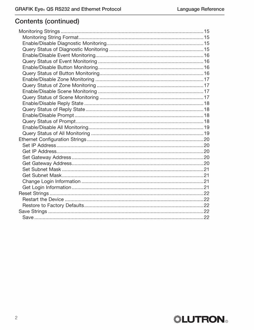
2
GRAFIK Eye® QS RS232 and Ethernet Protocol Language Reference
R
Monitoring Strings .......................................................................................................15Monitoring String Format..........................................................................................15Enable/Disable Diagnostic Monitoring......................................................................15Query Status of Diagnostic Monitoring ....................................................................15Enable/Disable Event Monitoring..............................................................................16Query Status of Event Monitoring ............................................................................16Enable/Disable Button Monitoring............................................................................16Query Status of Button Monitoring...........................................................................16Enable/Disable Zone Monitoring ..............................................................................17Query Status of Zone Monitoring .............................................................................17Enable/Disable Scene Monitoring ............................................................................17Query Status of Scene Monitoring ...........................................................................17Enable/Disable Reply State ......................................................................................18Query Status of Reply State .....................................................................................18Enable/Disable Prompt .............................................................................................18Query Status of Prompt............................................................................................18Enable/Disable All Monitoring...................................................................................19Query Status of All Monitoring .................................................................................19
Ethernet Configuration Strings ....................................................................................20Set IP Address ..........................................................................................................20Get IP Address..........................................................................................................20Set Gateway Address ...............................................................................................20Get Gateway Address...............................................................................................20Set Subnet Mask ......................................................................................................21Get Subnet Mask......................................................................................................21Change Login Information ........................................................................................21Get Login Information ...............................................................................................21
Reset Strings ...............................................................................................................22Restart the Device ....................................................................................................22Restore to Factory Defaults......................................................................................22
Save Strings ................................................................................................................22Save ..........................................................................................................................22
Contents (continued)
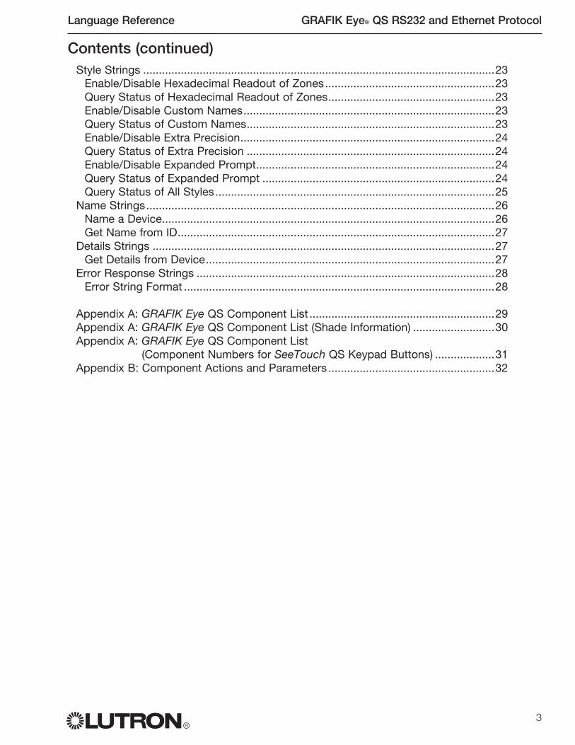
Language Reference GRAFIK Eye® QS RS232 and Ethernet Protocol
R3
Style Strings ................................................................................................................23Enable/Disable Hexadecimal Readout of Zones......................................................23Query Status of Hexadecimal Readout of Zones.....................................................23Enable/Disable Custom Names................................................................................23Query Status of Custom Names...............................................................................23Enable/Disable Extra Precision.................................................................................24Query Status of Extra Precision ...............................................................................24Enable/Disable Expanded Prompt............................................................................24Query Status of Expanded Prompt ..........................................................................24Query Status of All Styles.........................................................................................25
Name Strings...............................................................................................................26Name a Device..........................................................................................................26Get Name from ID.....................................................................................................27
Details Strings .............................................................................................................27Get Details from Device............................................................................................27
Error Response Strings ...............................................................................................28Error String Format ...................................................................................................28
Appendix A: GRAFIK Eye QS Component List ...........................................................29Appendix A: GRAFIK Eye QS Component List (Shade Information) ..........................30Appendix A: GRAFIK Eye QS Component List (Component Numbers for SeeTouch QS Keypad Buttons) ...................31Appendix B: Component Actions and Parameters .....................................................32
Contents (continued)
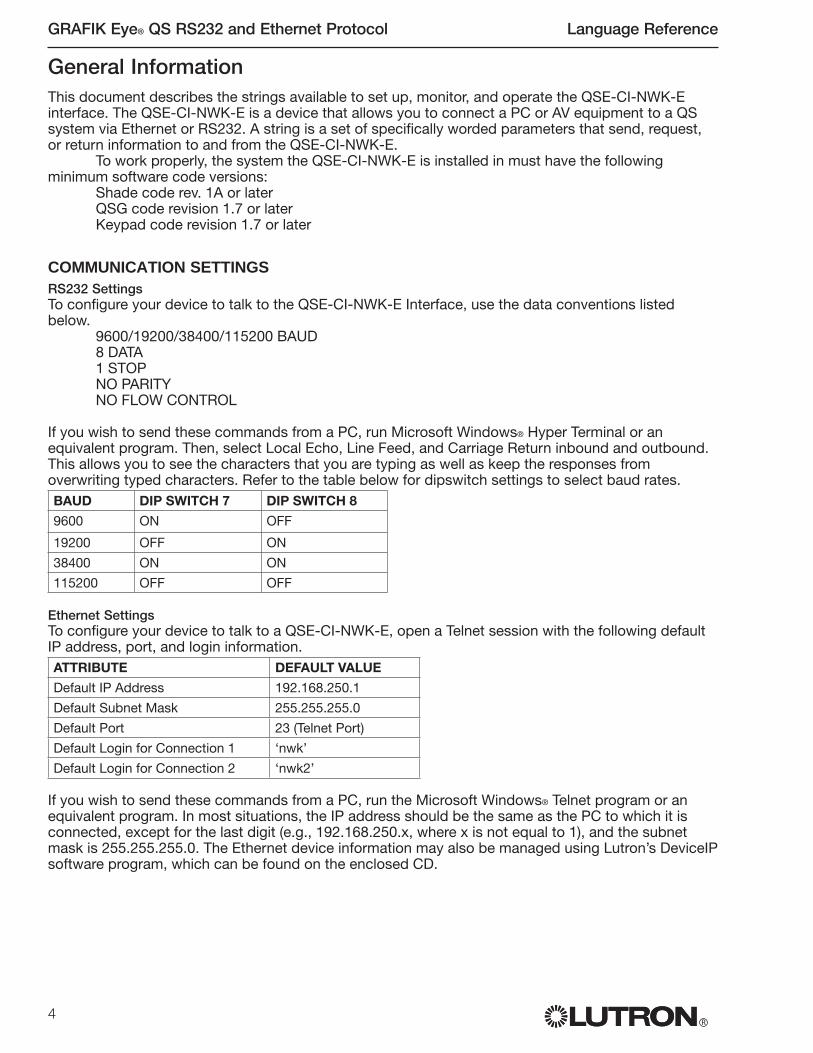
4
GRAFIK Eye® QS RS232 and Ethernet Protocol Language Reference
R
General InformationThis document describes the strings available to set up, monitor, and operate the QSE-CI-NWK-E interface. The QSE-CI-NWK-E is a device that allows you to connect a PC or AV equipment to a QS system via Ethernet or RS232. A string is a set of specifically worded parameters that send, request, or return information to and from the QSE-CI-NWK-E.
To work properly, the system the QSE-CI-NWK-E is installed in must have the following minimum software code versions:
Shade code rev. 1A or laterQSG code revision 1.7 or laterKeypad code revision 1.7 or later
COMMUNICATION SETTINGS
RS232 SettingsTo configure your device to talk to the QSE-CI-NWK-E Interface, use the data conventions listed below.
9600/19200/38400/115200 BAUD8 DATA1 STOPNO PARITYNO FLOW CONTROL
If you wish to send these commands from a PC, run Microsoft Windows® Hyper Terminal or an equivalent program. Then, select Local Echo, Line Feed, and Carriage Return inbound and outbound. This allows you to see the characters that you are typing as well as keep the responses from overwriting typed characters. Refer to the table below for dipswitch settings to select baud rates.BAUD DIP SWITCH 7 DIP SWITCH 8
9600 ON OFF
19200 OFF ON
38400 ON ON
115200 OFF OFF
Ethernet SettingsTo configure your device to talk to a QSE-CI-NWK-E, open a Telnet session with the following default IP address, port, and login information.ATTRIBUTE DEFAULT VALUE
Default IP Address 192.168.250.1
Default Subnet Mask 255.255.255.0
Default Port 23 (Telnet Port)
Default Login for Connection 1 ‘nwk’
Default Login for Connection 2 ‘nwk2’
If you wish to send these commands from a PC, run the Microsoft Windows® Telnet program or an equivalent program. In most situations, the IP address should be the same as the PC to which it is connected, except for the last digit (e.g., 192.168.250.x, where x is not equal to 1), and the subnet mask is 255.255.255.0. The Ethernet device information may also be managed using Lutron’s DeviceIP software program, which can be found on the enclosed CD.

LEDS AND WIRING TERMINALS
RS232 WIRING
For connection to any GRAFIK Eye QS RS232 Interface, use a DB9 RS232 cable. If you do not have this cable, the following table lists the connections you need to make one.
TYPICAL PC OR AV EQUIPMENTSIGNAL
PIN ON STANDARD 9-PIN CONNECTOR OR QSE
PIN ON STANDARD 25-PIN CONNECTOR
COM 5 7
TxD 3 2
RxD 2 3
ETHERNET WIRING
Wire out of the Ethernet port to PC or AV Equipment using CAT5 cable (maximum 328 feet/100 m) to connect to auxiliary equipment. The Ethernet Activity LED will light continuously when link is present and will flash when there is link activity. Ethernet network equipment and cables provided by third party vendors.
SERIAL ID NUMBERS
The QS link supports a maximum of 100 devices. Each device has a unique factory-assigned 8-character serial ID number. This serial ID number cannot be changed and is used to address the device on the link. The serial ID number appears on a label on each QS device.
When the serial ID number is used in any string (for example, DEVICE strings), it must be preceded by “0x”, which is the prefix preceding all hexadecimal numbers. (See String Format on the next page.) See the specific string examples for exact syntax.
Ethernet Link (to PC or AV Equipment)
QS Link to GRAFIK Eye QSControl Units and Wallstations
Female 9-pin RS232 Link (to PC or AV Equipment)
PELV (Class 2: USA) Wiring
Power(LED 1)
RS232 Link RX (LED 5)
RS232 Link TX (LED 4)
5
Language Reference GRAFIK Eye® QS RS232 and Ethernet Protocol
R
Ethernet Activity (LED 2)
Unused(LED 3)
DIP SwitchesQS Link RX (LED 7)
QS Link TX (LED 6)

6
GRAFIK Eye® QS RS232 and Ethernet Protocol Language Reference
R6
STRING FORMAT
• All strings are in ASCII characters• Each string is made up of fields separated by commas and terminated with a carriage return
(<CR> = 0Dh)• Strings are not case sensitive• Starting and trailing spaces will be ignored• Hexadecimal values must be preceded by “0x”.
STRING TYPES
The QSE supports the following command, query, and response strings:• Device• Ready• Monitoring• Ethernet• Reset • Save• Style• Name• Details• Error
There are four string types that can be sent or received by the interface: Commands, Queries, Responses, and Events. Each type of data will have a prefix to identify it. The prefix-identifiers are detailed below.
PREFIX TYPE DESCRIPTION
# COMMAND Command is sent to and interpreted by the processor via an integration point (RS232 or Ethernet)
? QUERY A request for the status of a part of the system
~ RESPONSE Response from QSE after a Query, Command or Event
~ EVENT An event is a result of a system change independent of the QSE-CI-NWK-E. For example, a user button press or a timeclock-initiated scene # change would produce an ~EVENT string
~ ERROR Errors in syntax will generate an ~ERROR response (see Error).
; COMMENT A string to be ignored by the QSE. If used within a line (after a command or query), everything including and after the ‘;’ will be ignored.
Response NotesFor all strings except the DEVICE command:- When a command is sent, the response will return a confirmation of the command that mimics the
command sent- When a query is sent, the response returns the information requested- When a query is sent that requests ”all” information, the response returns a list of the information
requested for each device, setting, or other component; each response is on its own line
For the DEVICE command:- If setting the scene # or the level, the response will return a confirmation of the command that
mimics the command sent- If the scene # or level changes, or there is a button event or button press/release, the QSE will
generate a response reflecting the new state- If setting a sequence, the response returns for each new scene #, as above- If setting zone lock or scene lock, no response is generated- If sending a master raise or master lower, a response is generated periodically (approximately every
10 seconds)

Language Reference GRAFIK Eye® QS RS232 and Ethernet Protocol
R7
STARTUP RESPONSE INFORMATION
When connected to power, the QSE-CI-NWK-E polls all the devices on the link for their names, and reads the zone and scene information for all GRAFIK Eye QS devices on the link. The device scene and zone information will generate ~DEVICE responses on power up.
The QSE-CI-NWK-E will generate a ~NAME response on startup only if the device name stored in the remote device differs from the name stored on the QSE-CI-NWK-E. The names are stored to the other devices when a NAME command is issued. It is important to note that these responses occur only on power up and do not occur upon connection to the QSE. These outputs may be turned on or off by setting or clearing the appropriate monitoring flags.
Please allow 10 seconds on startup for the QSE-CI-NWK-E to fully boot or restore power prior to sending commands.

8
GRAFIK Eye® QS RS232 and Ethernet Protocol Language Reference
R8
DEVICE STRING FORMAT EXPLANATIONS
String prefixes: # sending a command to the QS system ? sending a query to the QS system ~ getting a response or status change from the QS system
Serial ID number: Set at the factory for every device. Each one is a hexadecimal number made up of
8 ascii characteres preceded by ‘0x’. They are case insensitive (‘a’ = ‘A’). Examples: 0x000B18432 for serial ID number 0000B18432
0xFFFFFFFFF for all devicesComponent: The component number specifies the feature of the device. Component numbers vary
by device and are listed in Appendix A. Or, use the examples in the DEVICE section.
Action: The action to perform on the component. For example, if the component number is a
zone, the action might be ‘set level’. The actions are listed in appendix B.
Parameters: Parameters for the action. For example, if the action is ‘set level’, the first parameter is
a level percentage and the second parameter is a fade time. Parameters are listed with the actions in Appendix B.
Device StringsDevice integration strings allow the user to access components of the QS system. The user can read current scene and zone information through the ?DEVICE query, and can set the level of a light, the position of a shade, or the scene number of a GRAFIK Eye lighting controller through the #DEVICE command. Real-time device monitoring is set up through the #MONITORING command set, and then generates responses using the ~DEVICE format. Devices may be referred to by their serial ID numbers, or may be named and then referred to by that name. The custom name flag in the Style options only effects responses; for commands and queries, either the name or serial ID number may be used.
Queries with multiple responses (for multiple components and/or multiple devices) will generate responses on multiple lines.

Language Reference GRAFIK Eye® QS RS232 and Ethernet Protocol
R9
SET A SCENE # ON A GRAFIK EYE QS
Syntax #DEVICE,<ID>,141,7,<scene #><CR>ID See DEVICE string format141 Component = the scene controller of the GRAFIK Eye QS
(See Appendix A for a list of Components)7 Action = set the active scene #
(See Appendix B for a list of Component Actions)scene # Tells the component which scene # to set
Allowed values: 0 - 16 (0 is Off scene)Example Set the GRAFIK Eye QS with the serial ID number 00AC123D to
scene # 1 #DEVICE,0x00AC123D,141,7,1<CR>
Device Strings (continued)
QUERY THE CURRENT SCENE # ON A GRAFIK EYE QS
Syntax ?DEVICE,<ID>,141,7<CR>ID See DEVICE string format141 Component = the scene controller of the GRAFIK Eye QS
(See Appendix A for a list of Components)7 Action = get the active scene #
(See Appendix B for a list of Component Actions)Example Query the GRAFIK Eye QS with the serial ID number 00AC123D for
its current scene #?DEVICE,0x00AC123D,141,7<CR>
Response to query shows that the GRAFIK Eye QS is in scene #4~DEVICE,0x00AC123D,141,7,4
QUERY THE CURRENT SCENE # ON EACH GRAFIK EYE QS IN THE SYSTEM
Syntax ?DEVICE,ALL_DEVICES,141,7<CR>ALL_DEVICES All GRAFIK Eye QS control units on the link141 Component = the scene controller of the GRAFIK Eye QS
(See Appendix A for a list of Components)7 Action = get the active scene #
(See Appendix B for a list of Component Actions)Example Query each GRAFIK Eye QS on the system for its current scene #
?DEVICE,ALL_DEVICES,141,7<CR>
Response to query shows the current scene # of all GRAFIK EyeQS control units, in order by serial ID number. Each QS control unit’s status is displayed on a separate line, with the current scene # displayed as the last number in the string.~DEVICE,0x00AC123D,141,7,4~DEVICE,0x00AC226A,141,7,8~DEVICE,0x00AC709B,141,7,0

10
GRAFIK Eye® QS RS232 and Ethernet Protocol Language Reference
R
SET ZONE LOCK ON A GRAFIK EYE QS
Syntax #DEVICE,<ID>,141,15,<value><CR>ID See DEVICE string format141 Component = the scene controller of the GRAFIK Eye QS
(See Appendix A for a list of Components)15 Action = set the zone lock to On or Off
(See Appendix B for a list of Component Actions)value 0 = zone lock Off
1 = zone lock OnWhen zone lock is On, zone levels cannot be saved on the GRAFIK Eye QS in normal mode
Example Set the GRAFIK Eye QS with the serial ID number 00AC123D to turn zone lock On#DEVICE,0x00AC123D,141,15,1<CR>
Device Strings (continued)
SET SCENE LOCK ON A GRAFIK EYE QS
Syntax #DEVICE,<ID>,141,16,<value><CR>ID See DEVICE string format141 Component = the scene controller of the GRAFIK Eye QS
(See Appendix A for a list of Components)16 Action = set the scene lock to On or Off
(See Appendix B for a list of Component Actions)value 0 = scene lock Off
1 = scene lock OnWhen scene lock is On, scene #s cannot be changed from the GRAFIK Eye QS or from keypads programmed to it during normal operation
Example Set the GRAFIK Eye QS with the serial ID number 00AC123D to turn scene lock Off#DEVICE,0x00AC123D,141,16,0<CR>
START/STOP SEQUENCING ON A GRAFIK EYE QS
Syntax #DEVICE,<ID>,141,17,<value><CR>ID See DEVICE string format141 Component = the scene controller of the GRAFIK Eye QS
(See Appendix A for a list of Components)17 Action = set the status of sequencing between scene #s
(See Appendix B for a list of Component Actions)value 0 = sequencing off; current sequencing stops
1 = sequencing on; scene #s 1 to 4 sequence and repeat2 = sequencing on; scene #s 5 to 16 sequence and repeat
Example Set the GRAFIK Eye QS with the serial ID number 00AC123D to sequence scene #s 5 through 16#DEVICE,0x00AC123D,141,17,2<CR>

Language Reference GRAFIK Eye® QS RS232 and Ethernet Protocol
R11
START A MASTER RAISE OF ALL LIGHTING ZONES ON A GRAFIK EYE QS
Syntax #DEVICE,<ID>,141,18<CR>ID See DEVICE string format141 Component = the scene controller of the GRAFIK Eye QS
(See Appendix A for a list of Components)18 Action = raise the level of all lighting zones
(See Appendix B for a list of Component Actions)Example Set the GRAFIK Eye QS with the serial ID number 00AC123D to
start raising all lighting zones #DEVICE,0x00AC123D,141,18<CR>
Additional Information Follow this command with STOP A MASTER RAISE/LOWER. If none is issued, lights will go to 100% (Full On).
Device Strings (continued)
START A MASTER LOWER OF ALL LIGHTING ZONES ON A GRAFIK EYE QS
Syntax #DEVICE,<ID>,141,19<CR>ID See DEVICE string format141 Component = the scene controller of the GRAFIK Eye QS
(See Appendix A for a list of Components)19 Action = lower the level of all lighting zones
(See Appendix B for a list of Component Actions)Example Set the GRAFIK Eye QS with the serial ID number 00AC123D to
start lowering all lighting zones #DEVICE,0x00AC123D,141,19<CR>
Additional Information Follow this command with STOP A MASTER RAISE/LOWER. If none is issued, lights will go to 0% (Off).
STOP A MASTER RAISE OR LOWER OF ALL LIGHTING ZONES ON A GRAFIK EYE QS
Syntax #DEVICE,<ID>,141,20<CR>ID See DEVICE string format141 Component = the scene controller of the GRAFIK Eye QS
(See Appendix A for a list of Components)20 Action = stop raising or lowering the level of all lighting zones
(See Appendix B for a list of Component Actions)Example Set the GRAFIK Eye QS with the serial ID number 00AC123D to
stop raising or lowering all lighting zones #DEVICE,0x00AC123D,141,20<CR>

12
GRAFIK Eye® QS RS232 and Ethernet Protocol Language Reference
R
SET A ZONE LEVEL ON A GRAFIK EYE QS
Syntax #DEVICE,<ID>,<zone>,14,<level>,<fade><CR>ID See DEVICE string formatzone Tells the component which zone to set
Allowed values: 1 - 614 Action = fade a zone to a specified level
(See Appendix B for a list of Component Actions)level Tells the component what intensity to go to
Allowed values: 0 to 100, or 0.00 to 100.00, or 0x0000h to 0xFFFFhfade Specifies the time the light takes to arrive at the level
Format: Seconds; Minutes:Seconds; Hours:Minutes:SecondsExample Set the GRAFIK Eye QS with the serial ID number 00AC123D to
fade zone 2 to 36% over 1 minute and 30 seconds.#DEVICE,0x00AC123D,2,14,36,1:30<CR>
Device Strings (continued)
QUERY THE ZONE LEVEL ON A GRAFIK EYE QS
Syntax ?DEVICE,<ID>,<zone>,14<CR>ID See DEVICE string formatzone Tells the component which zone to query
Allowed values: 1 - 614 Action = get the zone target level (the level the zone is currently or
is fading to)(See Appendix B for a list of Component Actions)
Example Query the GRAFIK Eye QS with the serial ID number 00AC123D for the current level of zone 4.?DEVICE,0x00AC123D,4,14<CR>
Response to query shows that zone 4 of the GRAFIK Eye QS is at or going to 52%~DEVICE,0x00AC123D,4,14,52
QUERY THE LEVEL OF ALL ZONES ON A GRAFIK EYE QS
Syntax ?DEVICE,<ID>,0,14<CR>ID See DEVICE string format0 All zones on the GRAFIK Eye QS14 Action = get the zone level
(See Appendix B for a list of Component Actions)Example Query the GRAFIK Eye QS with the serial ID number 00AC123D for
the target level of all zones?DEVICE,0x00AC123D,0,14<CR>
Response to query shows the target level of all zones. Each zone is displayed on a separate line, with the target level (percentage) displayed as the last number in the string.~DEVICE,0x00AC123D,1,14,52~DEVICE,0x00AC123D,2,14,75~DEVICE,0x00AC123D,3,14,0~DEVICE,0x00AC123D,4,14,33~DEVICE,0x00AC123D,5,14,65~DEVICE,0x00AC123D,6,14,0
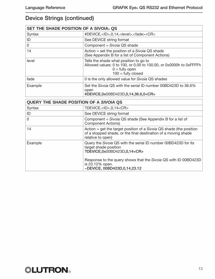
Language Reference GRAFIK Eye® QS RS232 and Ethernet Protocol
R13
SET THE SHADE POSITION OF A SIVOIA® QS
Syntax #DEVICE,<ID>,0,14,<level>,<fade><CR>ID See DEVICE string format0 Component = Sivoia QS shade14 Action = set the position of a Sivoia QS shade
(See Appendix B for a list of Component Actions)level Tells the shade what position to go to
Allowed values: 0 to 100, or 0.00 to 100.00, or 0x0000h to 0xFFFFh0 = fully open100 = fully closed
fade 0 is the only allowed value for Sivoia QS shades
Example Set the Sivoia QS with the serial ID number 00BD423D to 36.6% open#DEVICE,0x00BD423D,0,14,36.6,0<CR>
Device Strings (continued)
QUERY THE SHADE POSITION OF A SIVOIA QS
Syntax ?DEVICE,<ID>,0,14<CR>ID See DEVICE string format0 Component = Sivoia QS shade (See Appendix B for a list of
Component Actions)14 Action = get the target position of a Sivoia QS shade (the position
of a stopped shade, or the final destination of a moving shade relative to open)
Example Query the Sivoia QS with the serial ID number 00BD423D for its target shade position?DEVICE,0x00BD423D,0,14<CR>
Response to the query shows that the Sivoia QS with ID 00BD423D is 23.12% open.~DEVICE, 00BD423D,0,14,23.12
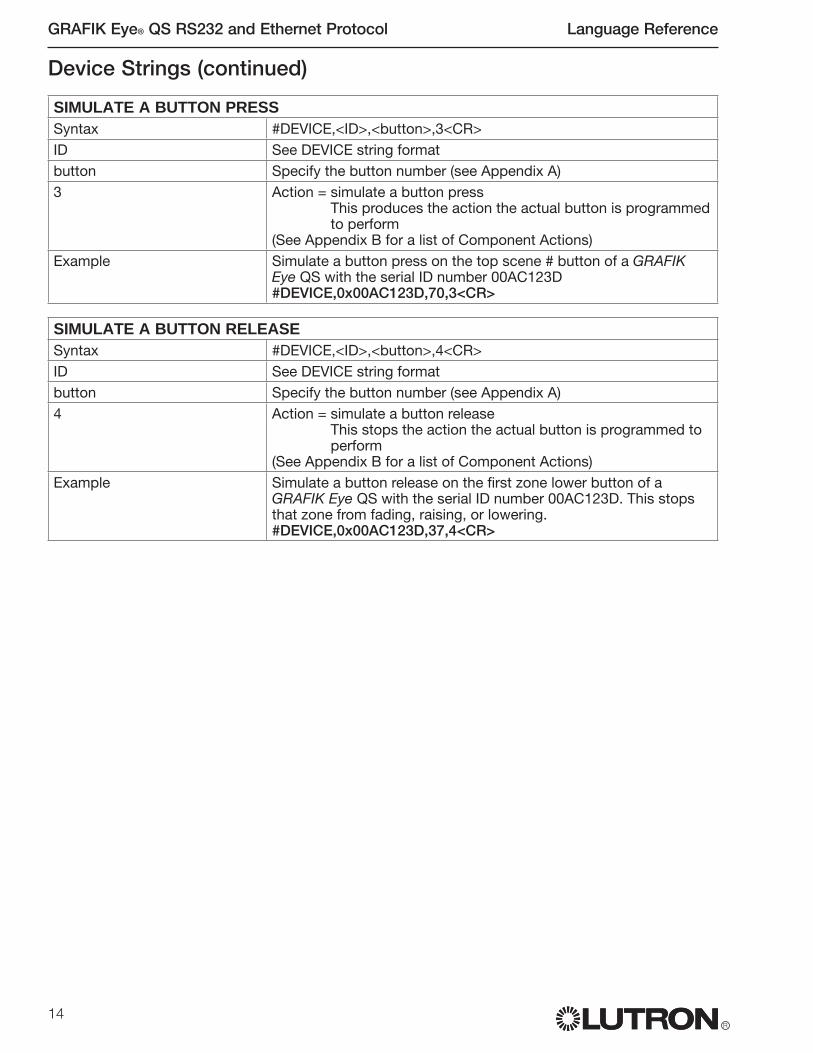
14
GRAFIK Eye® QS RS232 and Ethernet Protocol Language Reference
R
SIMULATE A BUTTON PRESS
Syntax #DEVICE,<ID>,<button>,3<CR>ID See DEVICE string formatbutton Specify the button number (see Appendix A)3 Action = simulate a button press
This produces the action the actual button is programmed to perform
(See Appendix B for a list of Component Actions)Example Simulate a button press on the top scene # button of a GRAFIK
Eye QS with the serial ID number 00AC123D #DEVICE,0x00AC123D,70,3<CR>
SIMULATE A BUTTON RELEASE
Syntax #DEVICE,<ID>,<button>,4<CR>ID See DEVICE string formatbutton Specify the button number (see Appendix A)4 Action = simulate a button release
This stops the action the actual button is programmed to perform
(See Appendix B for a list of Component Actions)Example Simulate a button release on the first zone lower button of a
GRAFIK Eye QS with the serial ID number 00AC123D. This stops that zone from fading, raising, or lowering.#DEVICE,0x00AC123D,37,4<CR>
Device Strings (continued)

Language Reference GRAFIK Eye® QS RS232 and Ethernet Protocol
R15
MONITORING STRING FORMAT (SPECIFIC EXAMPLES FOLLOW)
Syntax <type>MONITORING,<monitoring type>,<action><CR>type # command into the QS system
? query to the QS system~ response from the QS system or
event change from the QS systemmonitoring type 1 = diagnostic
2 = event (zone, button, and scene # combined)3 = button5 = zone8 = scene #11 = reply state12 = prompt state13 = name response (when a device name changes)255 = all monitoring
action 1 = enabled2 = disabled
Example Enable monitoring of zone events on linkmonitoring type (zone) = 5action (enable) = 1#MONITORING,5,1<CR>
Monitoring StringsMonitoring allows the user to determine what types of messages the system will report. Values are automatically saved. The user can temporarily change settings to hide or show information as desired.
When enabled, the zone, scene #, and property monitoring generate a ~DEVICE response for each system change that occurs. (See the ~DEVICE response for details.) Queries for all monitoring (255) will respond with one ~MONITORING response per monitoring type.
ENABLE/DISABLE DIAGNOSTIC MONITORING
Syntax #MONITORING,1,<action><CR>1 Monitoring type = diagnostic monitoring
~ERROR responses for bad commands (On by default)
action 1 = enabled2 = disabled
Example Enable diagnostic monitoring on link#MONITORING,1,1<CR>
QUERY STATUS OF DIAGNOSTIC MONITORING
Syntax ?MONITORING,1,<action><CR>1 Monitoring type = diagnostic monitoring
~ERROR responses for bad commands (On by default)
Example Query the QS system to check if diagnostic monitoring is enabled?MONITORING,1<CR>
Response (if enabled):~MONITORING,1,1<CR>
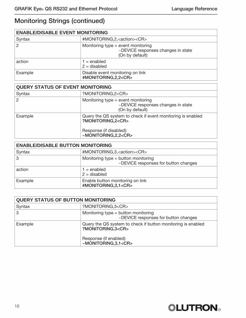
16
GRAFIK Eye® QS RS232 and Ethernet Protocol Language Reference
R
Monitoring Strings (continued)
ENABLE/DISABLE EVENT MONITORING
Syntax #MONITORING,2,<action><CR>2 Monitoring type = event monitoring
~DEVICE responses changes in state(On by default)
action 1 = enabled2 = disabled
Example Disable event monitoring on link#MONITORING,2,2<CR>
QUERY STATUS OF EVENT MONITORING
Syntax ?MONITORING,2<CR>2 Monitoring type = event monitoring
~DEVICE responses changes in state(On by default)
Example Query the QS system to check if event monitoring is enabled?MONITORING,2<CR>
Response (if disabled):~MONITORING,2,2<CR>
ENABLE/DISABLE BUTTON MONITORING
Syntax #MONITORING,3,<action><CR>3 Monitoring type = button monitoring
~DEVICE responses for button changesaction 1 = enabled
2 = disabledExample Enable button monitoring on link
#MONITORING,3,1<CR>
QUERY STATUS OF BUTTON MONITORING
Syntax ?MONITORING,3<CR>3 Monitoring type = button monitoring
~DEVICE responses for button changesExample Query the QS system to check if button monitoring is enabled
?MONITORING,3<CR>
Response (if enabled):~MONITORING,3,1<CR>

Language Reference GRAFIK Eye® QS RS232 and Ethernet Protocol
R17
ENABLE/DISABLE SCENE MONITORING
Syntax #MONITORING,8,<action><CR>8 Monitoring type = scene monitoring
~DEVICE responses for scene changesaction 1 = enabled
2 = disabledExample Enable scene monitoring on link
#MONITORING,8,1<CR>
QUERY STATUS OF SCENE MONITORING
Syntax ?MONITORING,8,<action><CR>8 Monitoring type = scene monitoring
~DEVICE responses for scene changesExample Query the QS system to check if scene monitoring is enabled
?MONITORING,8<CR>
Response (if enabled):~MONITORING,8,1<CR>
Monitoring Strings (continued)
ENABLE/DISABLE ZONE MONITORING
Syntax #MONITORING,5,<action><CR>5 Monitoring type = zone monitoring
~DEVICE responses for zone target changes for lights and shades
action 1 = enabled2 = disabled
Example Enable zone monitoring on link#MONITORING,5,1<CR>
QUERY STATUS OF ZONE MONITORING
Syntax ?MONITORING,5<CR>5 Monitoring type = zone monitoring
~DEVICE responses for zone target changesExample Query the QS system to check if zone monitoring is enabled
?MONITORING,5<CR>
Response (if enabled):~MONITORING,5,1<CR>
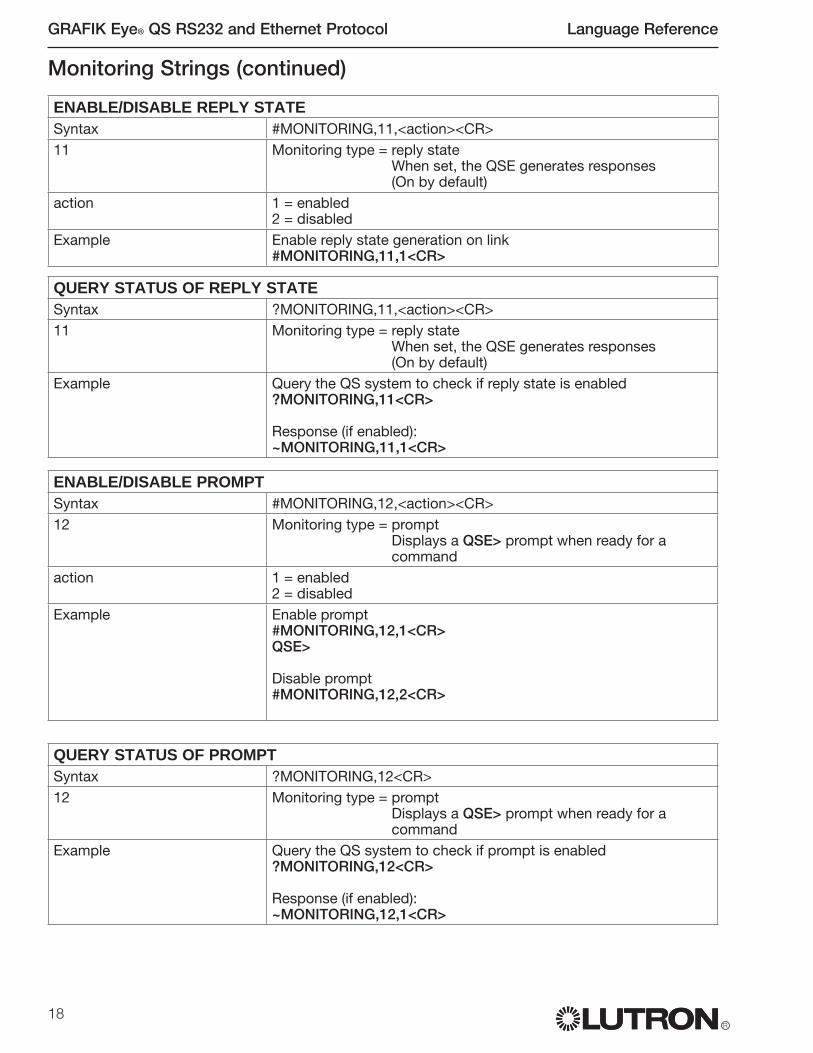
18
GRAFIK Eye® QS RS232 and Ethernet Protocol Language Reference
R
Monitoring Strings (continued)
ENABLE/DISABLE REPLY STATE
Syntax #MONITORING,11,<action><CR>11 Monitoring type = reply state
When set, the QSE generates responses(On by default)
action 1 = enabled2 = disabled
Example Enable reply state generation on link#MONITORING,11,1<CR>
QUERY STATUS OF REPLY STATE
Syntax ?MONITORING,11,<action><CR>11 Monitoring type = reply state
When set, the QSE generates responses(On by default)
Example Query the QS system to check if reply state is enabled?MONITORING,11<CR>
Response (if enabled):~MONITORING,11,1<CR>
ENABLE/DISABLE PROMPT
Syntax #MONITORING,12,<action><CR>12 Monitoring type = prompt
Displays a QSE> prompt when ready for a command
action 1 = enabled2 = disabled
Example Enable prompt#MONITORING,12,1<CR>QSE>
Disable prompt#MONITORING,12,2<CR>
QUERY STATUS OF PROMPT
Syntax ?MONITORING,12<CR>12 Monitoring type = prompt
Displays a QSE> prompt when ready for a command
Example Query the QS system to check if prompt is enabled?MONITORING,12<CR>
Response (if enabled):~MONITORING,12,1<CR>

Language Reference GRAFIK Eye® QS RS232 and Ethernet Protocol
R19
Monitoring Strings (continued)
ENABLE/DISABLE ALL MONITORING
Syntax #MONITORING,255,<action><CR>255 Monitoring type = All monitoring (except prompt and reply state)
Turns on all the monitoring options at the same time. Reply and Prompt must be turned on separately.
action 1 = enabled2 = disabled
Example Enable all monitoring (except Reply and Prompt) on link#MONITORING,255,1<CR>
QUERY STATUS OF ALL MONITORING
Syntax ?MONITORING,255<CR>255 Monitoring type = All monitoring (including prompt and reply state)
Checks the status of all the monitoring options at the same time.
Example Query the QS system to check the status of all monitoring (enabled or disabled?MONITORING,255<CR>
Sample Response Strings~MONITORING,1,2 Diagnostic monitoring is disabled~MONITORING,2,1 Event monitoring is enabled~MONITORING,3,1 Button monitoring is enabled~MONITORING,5,1 Zone monitoring is enabled~MONITORING,8,2 Scene monitoring is disabled~MONITORING,11,1 Reply is enabled~MONITORING,12,2 Prompt is disabled~MONITORING,13,1 Name response is enabled

20
GRAFIK Eye® QS RS232 and Ethernet Protocol Language Reference
R
SET IP ADDRESS
Syntax #ETHERNET,0,<address><CR>0 Set IP address<address> xxx.xxx.xxx.xxxExample Set IP address to 192.168.250.1
#ETHERNET,0,192.168.250.1<CR>
Ethernet Configuration StringsEthernet commands set up the Telnet connection. These settings may be changed over RS232 or Ethernet. The device must be power cycled (or reset with the #RESET command) before the changes take effect. See the Ethernet Settings section of General Information for more information.
GET IP ADDRESS
Syntax ?ETHERNET,0<CR>0 Get IP addressExample Query the QS system for the IP address
?ETHERNET,0<CR>
Response for the IP address:~ETHERNET,0,192.168.250.1<CR>
SET GATEWAY ADDRESS
Syntax #ETHERNET,1,<address><CR>1 Set gateway address<address> xxx.xxx.xxx.xxxExample Set gateway address to 10.2.4.1
#ETHERNET,1,192.168.250.1<CR>
GET GATEWAY ADDRESS
Syntax ?ETHERNET,1<CR>1 Get gateway addressExample Query the QS system for the gateway address
?ETHERNET,1<CR>
Response for the gateway:~ETHERNET,1,192.168.250.1<CR>

Language Reference GRAFIK Eye® QS RS232 and Ethernet Protocol
R21
Ethernet Strings (continued)
SET SUBNET MASK
Syntax #ETHERNET,2,<address><CR>2 Set subnet mask<address> xxx.xxx.xxx.xxxExample Set subnet mask to 255.255.255.0
#ETHERNET,2,255.255.255.0<CR>
GET SUBNET MASK
Syntax ?ETHERNET,2<CR>2 Get subnet maskExample Query the QS system for the subnet mask
?ETHERNET,2<CR>
Response for the gateway:~ETHERNET,2,255.255.255.0<CR>
CHANGE LOGIN INFORMATION
Syntax #ETHERNET,3,<user>,<old_login>,<new_login><CR>3 Change the login information for the specified user<user> 1 or 2<old_login> The current password for the specified user<new_login> The new desired password for the specified user
Up to 8 characters, case sensitiveExample Change the login for user 2 from ‘james’ to ‘Jimmy’
user = 2old_login = jamesnew_login = Jimmy#ETHERNET,3,2,james,Jimmy<CR>
Additional Information It is important to change the login information from the default. The default logins are published, and if left on an open network, the QSE-CI-NWK-E could be accessed by unauthorized users.
GET LOGIN INFORMATION
Syntax ?ETHERNET,3,<user><CR>3 Get the current login information<user> 1 or 2; 0 is all users<address> xxx.xxx.xxx.xxxExample Query the QS system for login information for all users
?ETHERNET,3,0<CR>
The response for the login query returns the login information for all users~ETHERNET,3,1,Jacob~ETHERNET,3,2,Jimmy
Query the QS system for login information for user 1?ETHERNET,3,1<CR>
The response for the login query returns the login information for all users 1 and user 2~ETHERNET,3,1,Jacob

22
GRAFIK Eye® QS RS232 and Ethernet Protocol Language Reference
R
Reset StringsThe reset command restarts the QSE-CI-NWK-E. It is critical for making Ethernet settings take effect, or for clearing out memory entries.
RESTART THE DEVICE
Syntax #RESET,0<CR>0 Resets the QSE-CI-NWK-E. This command is critical for making
the Ethernet settings take effect. Saved commands are retained; unsaved commands are lost.
Example Reset the QSE device you are connected to.#RESET,0<CR>
RESTORE TO FACTORY DEFAULTS
Syntax #RESET,1<CR>1 After a second (confirming) prompt, resets the name and
preferences database for the QSE-CI-NWK-E. Example Reset the preferences for the QSE device you are connected to;
preferences revert to the factory defaults.#RESET,1<CR>
Save StringsThe save command copies the contents of the name database, style settings and monitoring settings to permanent memory, so they can be maintained after a power failure. Note that the system has an autosave feature enabled, which initiates the SAVE command automatically approximately every 2 minutes.
SAVE
Syntax #SAVE<CR>Example Saves the QSE databases so that after a restart, the settings are
not lost.#SAVE<CR>
Response:~SAVE
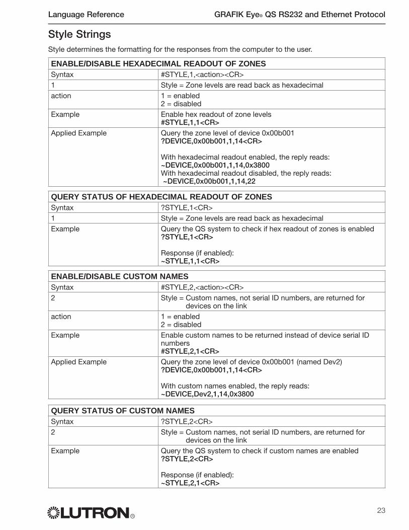
Language Reference GRAFIK Eye® QS RS232 and Ethernet Protocol
R23
Style StringsStyle determines the formatting for the responses from the computer to the user.
ENABLE/DISABLE HEXADECIMAL READOUT OF ZONES
Syntax #STYLE,1,<action><CR>1 Style = Zone levels are read back as hexadecimalaction 1 = enabled
2 = disabledExample Enable hex readout of zone levels
#STYLE,1,1<CR>Applied Example Query the zone level of device 0x00b001
?DEVICE,0x00b001,1,14<CR>
With hexadecimal readout enabled, the reply reads:~DEVICE,0x00b001,1,14,0x3800With hexadecimal readout disabled, the reply reads: ~DEVICE,0x00b001,1,14,22
QUERY STATUS OF HEXADECIMAL READOUT OF ZONES
Syntax ?STYLE,1<CR>1 Style = Zone levels are read back as hexadecimalExample Query the QS system to check if hex readout of zones is enabled
?STYLE,1<CR>
Response (if enabled):~STYLE,1,1<CR>
ENABLE/DISABLE CUSTOM NAMES
Syntax #STYLE,2,<action><CR>2 Style = Custom names, not serial ID numbers, are returned for
devices on the linkaction 1 = enabled
2 = disabledExample Enable custom names to be returned instead of device serial ID
numbers#STYLE,2,1<CR>
Applied Example Query the zone level of device 0x00b001 (named Dev2)?DEVICE,0x00b001,1,14<CR>
With custom names enabled, the reply reads:~DEVICE,Dev2,1,14,0x3800
QUERY STATUS OF CUSTOM NAMES
Syntax ?STYLE,2<CR>2 Style = Custom names, not serial ID numbers, are returned for
devices on the linkExample Query the QS system to check if custom names are enabled
?STYLE,2<CR>
Response (if enabled):~STYLE,2,1<CR>

24
GRAFIK Eye® QS RS232 and Ethernet Protocol Language Reference
R
Style Strings (continued)
ENABLE/DISABLE EXTRA PRECISION
Syntax #STYLE,3,<action><CR>3 Style = Zone levels are read back with 2 places past the decimal pointaction 1 = enabled
2 = disabledExample Enable zone levels to read back with 2 places past the decimal point
#STYLE,3,1<CR>Applied Example Query the zone level of device 0x00b001
?DEVICE,0x00b001,1,14<CR>
With extra precision enabled, the reply reads:~DEVICE,0x00b001,1,14,21.96With extra precision disabled, the reply reads:~DEVICE,0x00b001,1,14,22
QUERY STATUS OF EXTRA PRECISION
Syntax ?STYLE,3<CR>3 Style = Zone levels are read back with 2 places past the decimal pointExample Query the QS system to check if extra precision of zone level readout
is enabled?STYLE,3<CR>
Response (if enabled):~STYLE,3,1<CR>
ENABLE/DISABLE EXPANDED PROMPT
Syntax #STYLE,4,<action><CR>4 Style = When disabled, prompt reads: QSE>
When enabled, expanded prompt reads: <user>@<ID>>If connecting through RS232, <user> = RS232
action 1 = enabled2 = disabled
Example Enable expanded prompt to include the user and ID#STYLE,4,1<CR>
Applied Example Enable prompt#MONITORING,12,1<CR>
Prompt if expanded prompt enabled and connected over RS232, and QS is named Dev5:RS232@Dev5>Prompt if expanded prompt disabled:QSE>
QUERY STATUS OF EXPANDED PROMPT
Syntax ?STYLE,4<CR>4 Style = When disabled, prompt reads: QSE>
When enabled, expanded prompt reads: <user>@<ID>>Example Query the QS system to check if expanded prompt is enabled
?STYLE,4<CR>
Response (if enabled):~STYLE,4,1<CR>

Language Reference GRAFIK Eye® QS RS232 and Ethernet Protocol
R25
QUERY STATUS OF ALL STYLES
Syntax ?STYLE,255<CR>255 Style = Query the status of all styles (enabled or disabled)Example Query the QS system to check the staus of all styles
?STYLE,255<CR>
Sample Response Strings:~STYLE,1,1 Hexadecimal readout is enabled~STYLE,2,2 Custom names are disabled~STYLE,3,1 Extra precision is enabled~STYLE,4,2 Expanded prompt is disabled
Style Strings (continued)
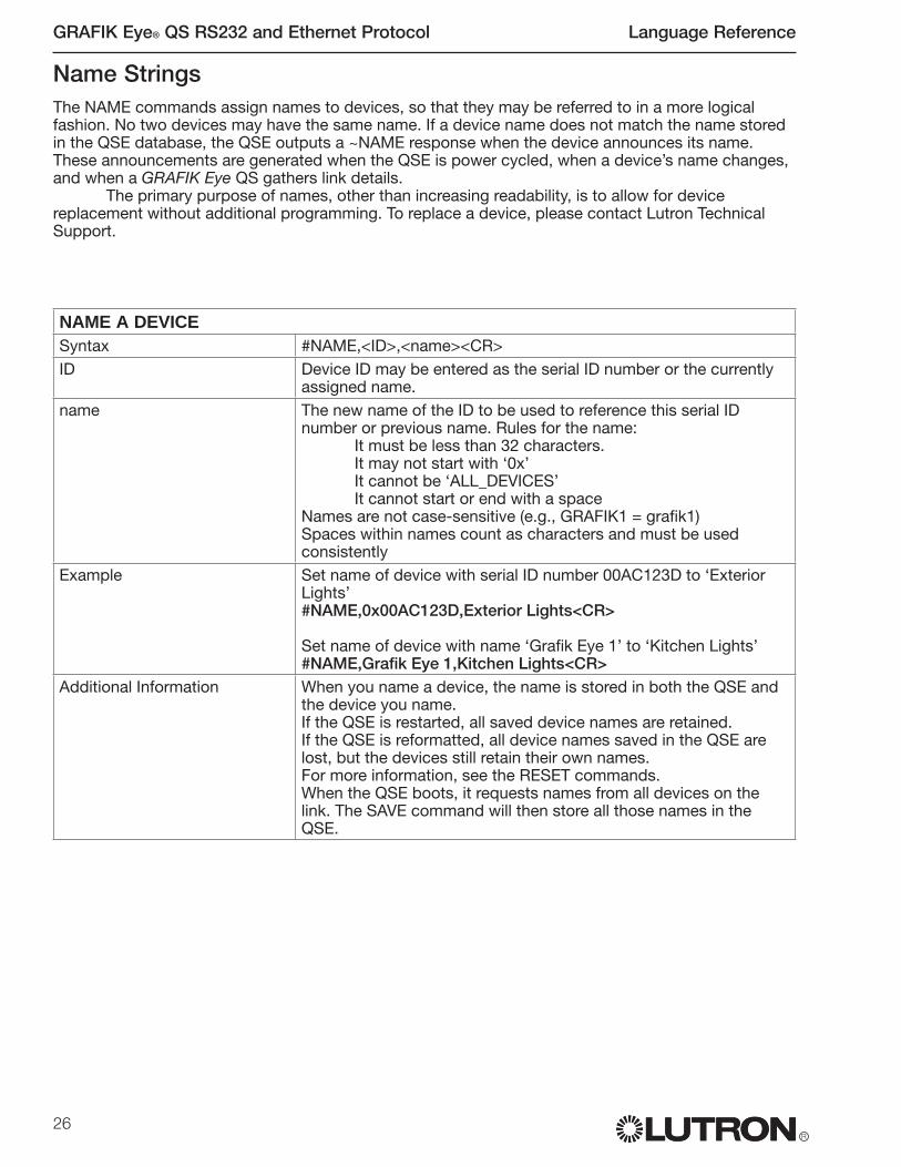
26
GRAFIK Eye® QS RS232 and Ethernet Protocol Language Reference
R
Name StringsThe NAME commands assign names to devices, so that they may be referred to in a more logical fashion. No two devices may have the same name. If a device name does not match the name stored in the QSE database, the QSE outputs a ~NAME response when the device announces its name. These announcements are generated when the QSE is power cycled, when a device’s name changes, and when a GRAFIK Eye QS gathers link details.
The primary purpose of names, other than increasing readability, is to allow for device replacement without additional programming. To replace a device, please contact Lutron Technical Support.
NAME A DEVICE
Syntax #NAME,<ID>,<name><CR>ID Device ID may be entered as the serial ID number or the currently
assigned name.name The new name of the ID to be used to reference this serial ID
number or previous name. Rules for the name:It must be less than 32 characters.It may not start with ‘0x’ It cannot be ‘ALL_DEVICES’It cannot start or end with a space
Names are not case-sensitive (e.g., GRAFIK1 = grafik1)Spaces within names count as characters and must be used consistently
Example Set name of device with serial ID number 00AC123D to ‘Exterior Lights’#NAME,0x00AC123D,Exterior Lights<CR>
Set name of device with name ‘Grafik Eye 1’ to ‘Kitchen Lights’#NAME,Grafik Eye 1,Kitchen Lights<CR>
Additional Information When you name a device, the name is stored in both the QSE and the device you name. If the QSE is restarted, all saved device names are retained.If the QSE is reformatted, all device names saved in the QSE are lost, but the devices still retain their own names.For more information, see the RESET commands.When the QSE boots, it requests names from all devices on the link. The SAVE command will then store all those names in the QSE.

Language Reference GRAFIK Eye® QS RS232 and Ethernet Protocol
R27
GET NAME FROM SERIAL ID NUMBER
Syntax ?NAME,<ID><CR>ID Device ID may be entered as the serial ID number or the currently
assigned name. Use ALL_DEVICES or 0xFFFFFFFF to query all devices on the link.
Example Get name of device with serial ID number 00AC123D?NAME,0x00AC123D<CR>
Response, if name of specified device is ‘Grafik Eye 1’~NAME, 0x00AC123D,Grafik Eye 1
Get serial ID number of device with name ‘Grafik Eye 1’?NAME,Grafik Eye 1<CR>
Response, if serial ID number of specified device is 00AC123D~NAME,Grafik Eye 1,0x00AC123D
Get names of all devices on the link?NAME,ALL_DEVICES<CR>
~NAME,Dev1,0x000b0001~NAME,Dev2,0x000b0002~NAME,Dev3,0x000b0003~NAME,Dev4,0x000b0004~NAME,Dev5,0x00250001
Name Strings (continued)
GET DETAILS FROM DEVICE
Syntax ?DETAILS,<ID><CR>ID Device ID may be entered as the serial ID number or the currently
assigned name. Use ALL_DEVICES or 0xFFFFFFFF to query all devices on the link.
Example Get details of device with serial ID number 00AC123D?DETAILS,0x00AC123D<CR>
Response (see explanation below~DETAILS,SN:0x00AC123D,NAME:Grafik Eye 1,FAMILY:GRAFIK_EYE(2),PRODUCT:QSG(1),CODE:1.70,BOOT:2.1,HW:1.1
Product family = GRAFIK EyeProduct model = QSGSoftware version = 1.70Boot code software version = 2.1Hardware version = 1.1
Details StringThe Details query returns information from a GRAFIK Eye QS device. Information includes product family, product model, software version, boot code oftware version, and hardware version.
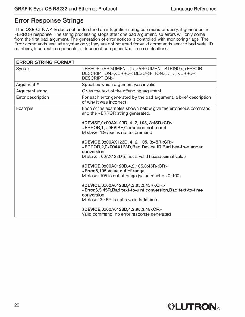
28
GRAFIK Eye® QS RS232 and Ethernet Protocol Language Reference
R
Error Response StringsIf the QSE-CI-NWK-E does not understand an integration string command or query, it generates an ~ERROR response. The string processing stops after one bad argument, so errors will only come from the first bad argument. The generation of error notices is controlled with monitoring flags. The Error commands evaluate syntax only; they are not returned for valid commands sent to bad serial ID numbers, incorrect components, or incorrect component/action combinations.
ERROR STRING FORMAT
Syntax ~ERROR,<ARGUMENT #>,<ARGUMENT STRING>,<ERROR DESCRIPTION>,<ERROR DESCRIPTION>, . . . , <ERROR DESCRIPTION>
Argument # Specifies which argument was invalidArgument string Gives the text of the offending argumentError description For each error generated by the bad argument, a brief description
of why it was incorrectExample Each of the examples shown below give the erroneous command
and the ~ERROR string generated.
#DEVISE,0x00AX123D, 4, 2, 105, 3:45R<CR>~ERROR,1,~DEVISE,Command not foundMistake: ‘Devise’ is not a command
#DEVICE,0x00AX123D, 4, 2, 105, 3:45R<CR>~ERROR,2,0x00AX123D,Bad Device ID,Bad hex-to-number conversionMistake : 00AX123D is not a valid hexadecimal value
#DEVICE,0x00A0123D,4,2,105,3:45R<CR>~Error,5,105,Value out of rangeMistake: 105 is out of range (value must be 0-100)
#DEVICE,0x00A0123D,4,2,95,3:45R<CR>~Error,6,3:45R,Bad text-to-uint conversion,Bad text-to-time conversionMistake: 3:45R is not a valid fade time
#DEVICE,0x00A0123D,4,2,95,3:45<CR>Valid command; no error response generated

Language Reference GRAFIK Eye® QS RS232 and Ethernet Protocol
R29
141 (Scene Controller; see Appendix B for actions)
}OK
1 2 3 4 5 6
APPENDIX A: GRAFIK EYE QS COMPONENT LIST:
COMPONENT NUMBERS FOR GRAFIK EYE QS BUTTONS
Button Components for Simulated Button PressesButton Press Active: These buttons execute the desired action upon the button pressButton Release Active: These buttons execute the desired action upon the button release
OK
1 2 3 4 5 6
70 (Scene # 1 button)71 (Scene # 2 button)76 (Scene # 3 button)77 (Scene # 4 button)83 (Scene Off button)
69 (OK button)71 (Timeclock button)
6 (Zone 6)5 (Zone 5)4 (Zone 4)
OK
1 2 3 4 5 6
66 (Zone 6 Raise)67 (Zone 6 Lower)
60 (Zone 5 Raise)61 (Zone 5 Lower)
54 (Zone 4 Raise)55 (Zone 4 Lower)
36 (Zone 1 Raise)37 (Zone 1 Lower)
42 (Zone 2 Raise)43 (Zone 2 Lower)
48 (Zone 3 Raise)49 (Zone 3 Lower)
74 (Master raise)75 (Master lower)
}}Release active
Press active
Button Components for Simulated Button PressesButton Press and Release: These buttons execute the desired action upon the button
press and release
Button Components
1 (Zone 1)2 (Zone 2)3 (Zone 3)

Language Reference GRAFIK Eye® QS RS232 and Ethernet Protocol
R
30
APPENDIX A: GRAFIK EYE QS COMPONENT LIST (SHADE INFORMATION)
COMPONENT ACTION DESCRIPTION VALID VALUES
0 7 Select Preassigned Preset 17 = Open18 = Closed26 = 75% open27 = 50% open28 = 25% open
14 Level Decimal Input Mode:0 – 1000.00 – 100.00Hexadecimal Input Mode:0x0000 – 0xFFFF
21 Time to destination (response only)
Seconds
1 2 3 4 5 6
50 (Shade Column 3 Open)51 (Shade Column 3 Preset)56 (Shade Column 3 Close)
50 (Shade Column 3 Raise)51 (Shade Column 3 Lower)
53 (Shade Column 2 Raise)52 (Shade Column 2 Lower)
47 (Shade Column 1 Raise)41 (Shade Column 1 Lower)
44 (Shade Column 2 Open)45 (Shade Column 2 Preset)46 (Shade Column 2 Close)
38 (Shade Column 1 Open)39 (Shade Column 1 Preset)40 (Shade Column 1 Close)

APPENDIX A: GRAFIK EYE QS COMPONENT LIST:
COMPONENT NUMBERS FOR SEETOUCH® QS KEYPAD BUTTONS
QSWS2-1B
4
QSWS2-2B
4
QSWS2-3B
4
QSWS2-5B QSWS2-7B
4
QSWS2-2BRL
4
QSWS2-3BRL
4
QSWS2-5BRL
QSWS2-2BRLIR
4
QSWS2-3BRLIR
4
QSWS2-5BRLIR
QSWS2-1RLD
QSWS2-2RLD
QSWS2-3BD
3
Language Reference GRAFIK Eye® QS RS232 and Ethernet Protocol
R31
32
432
5
1
321
765
3
1716 1716 1716 1716 1716
171617161716
32
432
5
1
3 32
432
5
1
321
65
191821
65
321
765
Note: Simulated button presses not enabled for keypads.

APPENDIX B: COMPONENT ACTIONS AND PARAMETERS
COMPONENT ACTION DESCRIPTION PARAMETER(S) VALID VALUES
0(used in Query)
0 All actions of all components
7 All scene values of all components
14 All zone intensities of all components
Button 3 Button press on device
4 Button release on device
SceneController
7 Select Scene # (Command)Scene Value (Query)
Scene number 0 – 16
15 Set Zone Lock (all zone intensity changes are temporary)
On or Off 0 is Off1 is On
16 Set Scene Lock (the device will not change scenes)
On or Off 0 is Off1 is On
17 Set Sequencing (the device cycles through scenes)
Which scene #s to sequence through
0 is no sequencing1 sequences scene #s 1-42 sequences scene #s 5-16
18 Master Raise
19 Master Lower
20 Stop Master Raise/Lower
ZoneController
14 Set zone level (Command)Zone Intensity (Query)
Level Decimal Input Mode:0 – 1000.00 – 100.00Hexadecimal Input Mode:0x0000 – 0xFFFFNote: NOt all levels can be achieved on all devices
Fade SecondsMinutes:SecondsHours:Minutes:Seconds
32
GRAFIK Eye® QS RS232 and Ethernet Protocol Language Reference
R

Lutron Electronics Co., Inc.Made and printed in U.S.A.P/N 040-241 Rev. B 3/08
R
Internet: www.lutron.comE-mail: [email protected]
WORLD HEADQUARTERSUSALutron Electronics Co., Inc.7200 Suter Road, Coopersburg, PA 18036-1299TEL +1.610.282.3800FAX +1.610.282.1243Toll-Free 1.888.LUTRON1Technical Support 1.800.523.9466
North and South America Technical HotlinesUSA, Canada, Caribbean: 1.800.523.9466Mexico: +1.888.235.2910Central/South America: +1.610.282.6701
EUROPEAN HEADQUARTERSUnited KingdomLutron EA Ltd.6 Sovereign Close, London, E1W 3JF United KingdomTEL +44.(0)20.7702.0657FAX +44.(0)20.7480.6899FREEPHONE (UK) 0800.282.107Technical support +44.(0)20.7680.4481
ASIAN HEADQUARTERSSingaporeLutron GL Ltd. 15 Hoe Chiang Road, #07-03 Euro Asia Centre, Singapore 089316TEL +65.6220.4666FAX +65.6220.4333
Asia Technical HotlinesNorthern China: 10.800.712.1536Southern China: 10.800.120.1536Hong Kong: 800.901.849Indonesia: 001.803.011.3994Japan: +81.3.5575.8411Macau: 0800.401Singapore: 800.120.4491Taiwan: 00.801.137.737Thailand: 001.800.120.665853Other countries: +65.6220.4666
Windows is a registered trademark of Microsoft, Inc.GRAFIK Eye, Sivoia, Lutron, and the Sunburst logo are registered trademarks and GRAFIK Eye QS is a trademark of Lutron Electronics Co., Inc. ©2008 Lutron Electronics, Inc.


Replacement Kit Instructions
QSGF Faceplate KitsQSGS Stripe KitsQSGB Button Kits
OK
1 2 3 4 5 6
LUTRON
OK
1 2 3 4 5 6
Faceplate ReplacementTo remove either faceplate, open it fully (flush to the wall), and pull up (for the top faceplate) or down (for the bottom faceplate) to pull both hinges out of their slots at the same time. Replace by sliding the hinges back into their slots.
Stripe ReplacementTo remove the stripe, lift the end and pull away from the faceplate until the tabs pop out of their slots. Replace plastic stripe by pressing the tabs back into their slots. For metal stripe, remove adhesive liner and press into place.
Button Kit ReplacementNote: Lighting and shade buttons are replaced the same way.To replace a column of buttons, insert the tip of your finger into the slot at the bottom of the button column, and gently lift up. The button kit should pop out. If you are adding a shade button kit where there is currently a blank cover, remove the lower faceplate (see above) and remove the blank cover. Replace the button kit by gently pressing it into the opening until it snaps into place, and replace the bottom faceplate if necessary.
R
Blank covers
Pull both hinges out at the same time
R
Lutron Electronics Co., Inc.Made and printed in U.S.A. 03/07P/N 032-180 Rev. A
Internet: www.lutron.comE-mail: [email protected] HeadquartersUSALutron Electronics Co., Inc.7200 Suter Road, Coopersburg, PA 18036-1299TEL +1.610.282.3800FAX +1.610.282.1243Toll-Free 1.888.LUTRON1Technical Support 1.800.523.9466BrazilLutron BZ do Brasil Ltda.AV, Brasil, 239, Jardim AmericaSao Paulo-SP, CEP: 01431-000, BrazilTEL +55.11.3885.5152FAX +55.11.3887.7138North and South America Technical HotlinesUSA, Canada, Caribbean: 1.800.523.9466Mexico: +1.888.235.2910Central/South America: +1.610.282.6701
European HeadquartersUnited KingdomLutron EA Ltd.6 Sovereign Close, London, E1W 3JF United KingdomTEL +44.(0)20.7702.0657FAX +44.(0)20.7480.6899FREEPHONE (UK) 0800.282.107Technical support +44.(0)20.7680.4481FranceLutron LTC, S.A.R.L.90 rue de Villiers, 92300 Levallois-Perret FranceTEL +33.(0)1.41.05.42.80FAX +33.(0)1.41.05.01.80FREEPHONE 0800.90.12.18GermanyLutron Electronics GmbH, Landsberger Allee 201, 13055 Berlin, GermanyTEL +49.(0)30.9710.4590FAX +49.(0)30.9710.4591FREEPHONE 00800.5887.6635ItalyLutron LDV, S.r.l.FREEPHONE 800.979.208Spain, BarcelonaLutron CC, S.R.L.Gran Via del Carlos III, 84, planta 3a, 08028, Barcelona, SpainTEL +34.93.496.57.42FAX +34.93.496.57.01FREEPHONE 0900.948.944Spain, MadridLutron CC, S.R.L.Calle Orense, 85, 28020 Madrid, SpainTEL +34.91.567.84.79FAX +34.91.567.84.78FREEPHONE 0900.948.944
Asian HeadquartersSingaporeLutron GL Ltd. 15 Hoe Chiang Road, #07-03 Euro Asia Centre, Singapore 089316TEL +65.6220.4666FAX +65.6220.4333China, BeijingLutron GL Ltd. Beijing Representative Office5th Floor, China Life Tower No. 16 Chaowai Street, Chaoyang District, Beijing 100020 ChinaTEL +86.10.5877.1817FAX +86.10.5877.1816China, GuangzhouLutron GL Ltd. Guangzhou Representative OfficeSuite A09, 23/F Tower A, Centre Plaza161 Lin He Xi Lu, Tian He District, Guang-zhou 510620 ChinaTEL +86.20.2885.8266FAX +86.20.2885.8366China, ShanghaiLutron GL Ltd., Shanghai Representative OfficeSuite 07, 39th Floor, Plaza 661266 Nan Jing West Road, Shanghai, 200040 ChinaTEL +86.21.6288.1473FAX +86.21.6288.1751China, Hong KongLutron GL Ltd.Unit 2808, 28/F, 248 Queen’s Road EastWanchai, Hong KongTEL +852.2104.7733FAX +852.2104.7633
JapanLutron Asuka Co. Ltd.No. 16 Kowa Building, 4F, 1-9-20Akasaka, Minato-ku, Tokyo 107-0052 JapanTEL +81.3.5575.8411FAX +81.3.5575.8420FREEPHONE 0120.083.417Asia Technical HotlinesNorthern China: 10.800.712.1536Southern China: 10.800.120.1536Hong Kong: 800.901.849Indonesia: 001.803.011.3994Japan: +81.3.5575.8411Macau: 0800.401Singapore: 800.120.4491Taiwan: 00.801.137.737Thailand: 001.800.120.665853Other countries: +800.120.4491
Warranty and Contact InformationLutron Electronics Co., Inc.One Year Limited Warranty
For a period of one year from the date of purchase, and subject to the exclusions and restrictions described below, Lutron warrants each new unit to be free from manufacturing defects. Lutron will, at its option, either repair the defective unit or issue a credit equal to the purchase price of the defective unit to the Customer against the purchase price of comparable replacement part purchased from Lutron.Replacements for the unit provided by Lutron or, at its sole discretion, an approved vendor may be new, used, repaired, reconditioned, and/or made by a different manufacturer.
If the unit is commissioned by Lutron or a Lutron approved third party as part of a Lutron commissioned lighting control system, the term of this warranty will be extended, and any credits against the cost of replacement parts will be prorated, in accordance with the warranty issued with the commissioned system, except that the term of the unit’s warranty term will be measured from the date of its commissioning.EXCLUSIONS AND RESTRICTIONS This Warranty does not cover, and Lutron and its suppliers are not responsible for:1. Damage, malfunction or inoperability diagnosed by Lutron or a Lutron approved third party as caused by normal wear and tear, abuse, misuse, incorrect installation, neglect, accident, interference or environmental factors, such as (a) use of incorrect line voltages, fuses or circuit breakers; (b) failure to install, maintain and operate the unit pursuant to the operating instructions provided by Lutron and the applicable provisions of the National Electrical Code and of the Safety Standards of Underwriter’s Laboratories; (c) use of incompatible devices or accessories; (d) improper or insufficient ventilation; (e) unauthorized repairs or adjustments; (f) vandalism; or (g) an act of God, such as fire, lightning, flooding, tornado, earthquake, hurricane or other problems beyond Lutron’s control.2. On-site labor costs to diagnose issues with, and to remove, repair, replace, adjust, reinstall and/or reprogram the unit or any of its components.3. Equipment and parts external to the unit, including those sold or supplied by Lutron (which may be covered by a separate warranty).4. The cost of repairing or replacing other property that is damaged when the unit does not work properly, even if the damage was caused by the unit.
EXCEPT AS EXPRESSLY PROVIDED IN THIS WARRANTY, THERE ARE NO EXPRESS OR IMPLIED WARRANTIES OF ANY TYPE, INCLUDING ANY IMPLIED WARRANTIES OF FITNESS FOR A PARTICULAR PURPOSE OR MERCHANTABILITY. LUTRON DOES NOT WARRANT THAT THE UNIT WILL OPERATE WITHOUT INTERRUPTION OR BE ERROR FREE.
NO LUTRON AGENT, EMPLOYEE OR REPRESENTATIVE HAS ANY AUTHORITY TO BIND LUTRON TO ANY AFFIRMATION, REPRESENTATION OR WARRANTY CONCERNING THE UNIT. UNLESS AN AFFIRMATION, REPRESENTATION OR WARRANTY MADE BY AN AGENT, EMPLOYEE OR REPRESENTATIVE IS SPECIFICALLY INCLUDED HEREIN, OR IN STANDARD PRINTED MATERIALS PROVIDED BY LUTRON, IT DOES NOT FORM A PART OF THE BASIS OF ANY BARGAIN BETWEEN LUTRON AND CUSTOMER AND WILL NOT IN ANY WAY BE ENFORCEABLE BY CUSTOMER.
IN NO EVENT WILL LUTRON OR ANY OTHER PARTY BE LIABLE FOR EXEMPLARY, CONSEQUENTIAL, INCIDENTAL OR SPECIAL DAMAGES (INCLUDING, BUT NOT LIMITED TO, DAMAGES FOR LOSS OF PROFITS,CONFIDENTIAL OR OTHER INFORMATION, OR PRIVACY; BUSINESS INTERRUPTION; PERSONAL INJURY; FAILURE TO MEET ANY DUTY, INCLUDING OF GOOD FAITH OR OF REASONABLE CARE; NEGLIGENCE, OR ANY OTHER PECUNIARY OR OTHER LOSS WHATSOEVER), NOR FOR ANY REPAIR WORK UNDERTAKEN WITHOUT LUTRON’S WRITTEN CONSENT ARISING OUT OF OR IN ANY WAY RELATED TO THE INSTALLATION, DEINSTALLATION, USE OF OR INABILITY TO USE THE UNIT OR OTHERWISE UNDER OR IN CONNECTION WITH ANY PROVISION OF THIS WARRANTY, OR ANY AGREEMENT INCORPORATING THIS WARRANTY, EVEN IN THE EVENT OF THE FAULT, TORT (INCLUDING NEGLIGENCE), STRICT LIABILITY, BREACH OF CONTRACT OR BREACH OF WARRANTY OF LUTRON OR ANY SUPPLIER, AND EVEN IF LUTRON OR ANY OTHER PARTY WAS ADVISED OF THE POSSIBILITY OF SUCH DAMAGES.
NOTWITHSTANDING ANY DAMAGES THAT CUSTOMER MIGHT INCUR FOR ANY REASON WHATSOEVER (INCLUDING, WITHOUT LIMITATION, ALL DIRECT DAMAGES AND ALL DAMAGES LISTED ABOVE), THE ENTIRE LIABILITY OF LUTRON AND OF ALL OTHER PARTIES UNDER THIS WARRANTY On ANY CLAIM FOR DAMAGES ARISING OUT OF OR IN CONNECTION WITH
THE MANUFACTURE, SALE, INSTALLATION, DELIVERY, USE, REPAIR, OR REPLACEMENT OF THE UNIT, OR ANY AGREEMENT INCORPORATING THIS WARRANTY, AND CUSTOMER’S SOLE REMEDY FOR THE FOREGOING, WILL BE LIMITED TO THE AMOUNT PAID TO LUTRON BY CUSTOMER FOR THE UNIT. THE FOREGOING LIMITATIONS, EXCLUSIONS AND DISCLAIMERS WILL APPLY TO THE MAXIMUM EXTENT ALLOWED BY APPLICABLE LAW, EVEN IF ANY REMEDY FAILS ITS ESSENTIAL PURPOSE. TO MAKE A WARRANTY CLAIM
To make a warranty claim, promptly notify Lutron within the warranty period described above by calling the Lutron Technical Support Center at (800) 523-9466. Lutron, in its sole discretion, will determine what action, if any, is required under this warranty. To better enable Lutron to address a warranty claim, have the unit’s serial and model numbers available when making the call. If Lutron, in its sole discretion, determines that an on-site visit or other remedial action is necessary, Lutron may send a Lutron Services Co. representative or coordinate the dispatch of a representative from a Lutron approved vendor to Customer’s site, and/or coordinate a warranty service call between Customer and a Lutron approved vendor.
This warranty gives you specific legal rights, and you may also have other rights which vary from state to state. Some states do not allow limitations on how long an implied warranty lasts, so the above limitation may not apply to you. Some states do not allow the exclusion or limitation of incidental or consequential damages, so the above limitation or exclusion may not apply to you.
These products may be covered under one or more of the following U.S. patents: D461,782; and corresponding foreign patents. Other U.S. and foreign patents may be pending.
Lutron, the sunburst logo, GRAFIK Eye are registered trademarks of Lutron Electronics Co., Inc.
© 2007 Lutron Electronics Co., Inc.
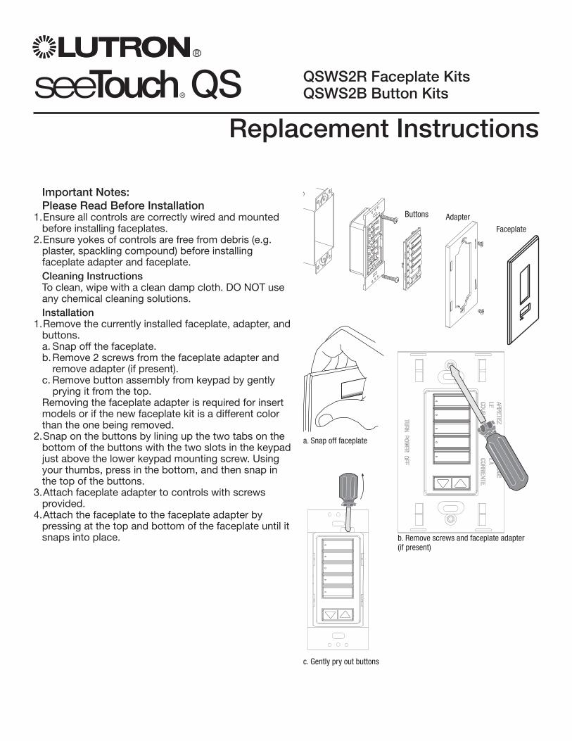
Replacement Instructions
QSWS2R Faceplate KitsQSWS2B Button Kits
R
Important Notes: Please Read Before Installation
1. Ensure all controls are correctly wired and mounted before installing faceplates.
2. Ensure yokes of controls are free from debris (e.g. plaster, spackling compound) before installing faceplate adapter and faceplate.Cleaning InstructionsTo clean, wipe with a clean damp cloth. DO NOT use any chemical cleaning solutions.Installation
1. Remove the currently installed faceplate, adapter, and buttons.
a. Snap off the faceplate. b. Remove 2 screws from the faceplate adapter and
remove adapter (if present). c. Remove button assembly from keypad by gently
prying it from the top. Removing the faceplate adapter is required for insert
models or if the new faceplate kit is a different color than the one being removed.
2. Snap on the buttons by lining up the two tabs on the bottom of the buttons with the two slots in the keypad just above the lower keypad mounting screw. Using your thumbs, press in the bottom, and then snap in the top of the buttons.
3. Attach faceplate adapter to controls with screws provided.
4. Attach the faceplate to the faceplate adapter by pressing at the top and bottom of the faceplate until it snaps into place.
Buttons Adapter
Faceplate
a. Snap off faceplate
b. Remove screws and faceplate adapter (if present)
c. Gently pry out buttons

R
Lutron Electronics Co., Inc.Made and printed in U.S.A. 03/07P/N 032-181 Rev. A
Internet: www.lutron.comE-mail: [email protected] HeadquartersUSALutron Electronics Co., Inc.7200 Suter Road, Coopersburg, PA 18036-1299TEL +1.610.282.3800FAX +1.610.282.1243Toll-Free 1.888.LUTRON1Technical Support 1.800.523.9466BrazilLutron BZ do Brasil Ltda.AV, Brasil, 239, Jardim AmericaSao Paulo-SP, CEP: 01431-000, BrazilTEL +55.11.3885.5152FAX +55.11.3887.7138North and South America Technical HotlinesUSA, Canada, Caribbean: 1.800.523.9466Mexico: +1.888.235.2910Central/South America: +1.610.282.6701
European HeadquartersUnited KingdomLutron EA Ltd.6 Sovereign Close, London, E1W 3JF United KingdomTEL +44.(0)20.7702.0657FAX +44.(0)20.7480.6899FREEPHONE (UK) 0800.282.107Technical support +44.(0)20.7680.4481FranceLutron LTC, S.A.R.L.90 rue de Villiers, 92300 Levallois-Perret FranceTEL +33.(0)1.41.05.42.80FAX +33.(0)1.41.05.01.80FREEPHONE 0800.90.12.18GermanyLutron Electronics GmbH, Landsberger Allee 201, 13055 Berlin, GermanyTEL +49.(0)30.9710.4590FAX +49.(0)30.9710.4591FREEPHONE 00800.5887.6635ItalyLutron LDV, S.r.l.FREEPHONE 800.979.208Spain, BarcelonaLutron CC, S.R.L.Gran Via del Carlos III, 84, planta 3a, 08028, Barcelona, SpainTEL +34.93.496.57.42FAX +34.93.496.57.01FREEPHONE 0900.948.944Spain, MadridLutron CC, S.R.L.Calle Orense, 85, 28020 Madrid, SpainTEL +34.91.567.84.79FAX +34.91.567.84.78FREEPHONE 0900.948.944
Asian HeadquartersSingaporeLutron GL Ltd. 15 Hoe Chiang Road, #07-03 Euro Asia Centre, Singapore 089316TEL +65.6220.4666FAX +65.6220.4333China, BeijingLutron GL Ltd. Beijing Representative Offi ce5th Floor, China Life Tower No. 16 Chaowai Street, Chaoyang District, Beijing 100020 ChinaTEL +86.10.5877.1817FAX +86.10.5877.1816China, GuangzhouLutron GL Ltd. Guangzhou Representative Offi ceSuite A09, 23/F Tower A, Centre Plaza161 Lin He Xi Lu, Tian He District, Guang-zhou 510620 ChinaTEL +86.20.2885.8266FAX +86.20.2885.8366China, ShanghaiLutron GL Ltd., Shanghai Representative Offi ce Suite 07, 39th Floor, Plaza 661266 Nan Jing West Road, Shanghai, 200040 ChinaTEL +86.21.6288.1473FAX +86.21.6288.1751China, Hong KongLutron GL Ltd.Unit 2808, 28/F, 248 Queen’s Road EastWanchai, Hong KongTEL +852.2104.7733FAX +852.2104.7633
JapanLutron Asuka Co. Ltd.No. 16 Kowa Building, 4F, 1-9-20Akasaka, Minato-ku, Tokyo 107-0052 JapanTEL +81.3.5575.8411FAX +81.3.5575.8420FREEPHONE 0120.083.417Asia Technical HotlinesNorthern China: 10.800.712.1536Southern China: 10.800.120.1536Hong Kong: 800.901.849Indonesia: 001.803.011.3994Japan: +81.3.5575.8411Macau: 0800.401Singapore: 800.120.4491Taiwan: 00.801.137.737Thailand: 001.800.120.665853Other countries: +800.120.4491
Warranty and Contact InformationLutron Electronics Co., Inc.One Year Limited Warranty For a period of one year from the date of purchase, and subject to the exclusions and restrictions described below, Lutron warrants each new unit to be free from manufacturing defects. Lutron will, at its option, either repair the defective unit or issue a credit equal to the purchase price of the defective unit to the Customer against the purchase price of comparable replacement part purchased from Lutron. Replacements for the unit provided by Lutron or, at its sole discretion, an approved vendor may be new, used, repaired, reconditioned, and/or made by a different manufacturer. If the unit is commissioned by Lutron or a Lutron approved third party as part of a Lutron commissioned lighting control system, the term of this warranty will be extended, and any credits against the cost of replacement parts will be prorated, in accordance with the warranty issued with the commissioned system, except that the term of the unit’s warranty term will be measured from the date of its commissioning.EXCLUSIONS AND RESTRICTIONS This Warranty does not cover, and Lutron and its suppliers are not responsible for:1. Damage, malfunction or inoperability diagnosed by Lutron or a Lutron approved third party as caused by normal wear and tear, abuse, misuse, incorrect installation, neglect, accident, interference or environmental factors, such as (a) use of incorrect line voltages, fuses or circuit breakers; (b) failure to install, maintain and operate the unit pursuant to the operating instructions provided by Lutron and the applicable provisions of the National Electrical Code and of the Safety Standards of Underwriter’s Laboratories; (c) use of incompatible devices or accessories; (d) improper or insuffi cient ventilation; (e) unauthorized repairs or adjustments; (f) vandalism; or (g) an act of God, such as fi re, lightning, fl ooding, tornado, earthquake, hurricane or other problems beyond Lutron’s control.2. On-site labor costs to diagnose issues with, and to remove, repair, replace, adjust, reinstall and/or reprogram the unit or any of its components.3. Equipment and parts external to the unit, including those sold or supplied by Lutron (which may be covered by a separate warranty).4. The cost of repairing or replacing other property that is damaged when the unit does not work properly, even if the damage was caused by the unit.
EXCEPT AS EXPRESSLY PROVIDED IN THIS WARRANTY, THERE ARE NO EXPRESS OR IMPLIED WARRANTIES OF ANY TYPE, INCLUDING ANY IMPLIED WARRANTIES OF FITNESS FOR A PARTICULAR PURPOSE OR MERCHANTABILITY. LUTRON DOES NOT WARRANT THAT THE UNIT WILL OPERATE WITHOUT INTERRUPTION OR BE ERROR FREE. NO LUTRON AGENT, EMPLOYEE OR REPRESENTATIVE HAS ANY AUTHORITY TO BIND LUTRON TO ANY AFFIRMATION, REPRESENTATION OR WARRANTY CONCERNING THE UNIT. UNLESS AN AFFIRMATION, REPRESENTATION OR WARRANTY MADE BY AN AGENT, EMPLOYEE OR REPRESENTATIVE IS SPECIFICALLY INCLUDED HEREIN, OR IN STANDARD PRINTED MATERIALS PROVIDED BY LUTRON, IT DOES NOT FORM A PART OF THE BASIS OF ANY BARGAIN BETWEEN LUTRON AND CUSTOMER AND WILL NOT IN ANY WAY BE ENFORCEABLE BY CUSTOMER. IN NO EVENT WILL LUTRON OR ANY OTHER PARTY BE LIABLE FOR EXEMPLARY, CONSEQUENTIAL, INCIDENTAL OR SPECIAL DAMAGES (INCLUDING, BUT NOT LIMITED TO, DAMAGES FOR LOSS OF PROFITS, CONFIDENTIAL OR OTHER INFORMATION, OR PRIVACY; BUSINESS INTERRUPTION; PERSONAL INJURY; FAILURE TO MEET ANY DUTY, INCLUDING OF GOOD FAITH OR OF REASONABLE CARE; NEGLIGENCE, OR ANY OTHER PECUNIARY OR OTHER LOSS WHATSOEVER), NOR FOR ANY REPAIR WORK UNDERTAKEN WITHOUT LUTRON’S WRITTEN CONSENT ARISING OUT OF OR IN ANY WAY RELATED TO THE INSTALLATION, DEINSTALLATION, USE OF OR INABILITY TO USE THE UNIT OR OTHERWISE UNDER OR IN CONNECTION WITH ANY PROVISION OF THIS WARRANTY, OR ANY AGREEMENT INCORPORATING THIS WARRANTY, EVEN IN THE EVENT OF THE FAULT, TORT (INCLUDING NEGLIGENCE), STRICT LIABILITY, BREACH OF CONTRACT OR BREACH OF WARRANTY OF LUTRON OR ANY SUPPLIER, AND EVEN IF LUTRON OR ANY OTHER PARTY WAS ADVISED OF THE POSSIBILITY OF SUCH DAMAGES. NOTWITHSTANDING ANY DAMAGES THAT CUSTOMER MIGHT INCUR FOR ANY REASON WHATSOEVER (INCLUDING, WITHOUT LIMITATION, ALL DIRECT DAMAGES AND ALL DAMAGES LISTED ABOVE), THE ENTIRE LIABILITY OF LUTRON AND OF ALL OTHER PARTIES UNDER THIS WARRANTY On ANY CLAIM FOR DAMAGES ARISING OUT OF OR IN CONNECTION WITH
THE MANUFACTURE, SALE, INSTALLATION, DELIVERY, USE, REPAIR, OR REPLACEMENT OF THE UNIT, OR ANY AGREEMENT INCORPORATING THIS WARRANTY, AND CUSTOMER’S SOLE REMEDY FOR THE FOREGOING, WILL BE LIMITED TO THE AMOUNT PAID TO LUTRON BY CUSTOMER FOR THE UNIT. THE FOREGOING LIMITATIONS, EXCLUSIONS AND DISCLAIMERS WILL APPLY TO THE MAXIMUM EXTENT ALLOWED BY APPLICABLE LAW, EVEN IF ANY REMEDY FAILS ITS ESSENTIAL PURPOSE. TO MAKE A WARRANTY CLAIM To make a warranty claim, promptly notify Lutron within the warranty period described above by calling the Lutron Technical Support Center at (800) 523-9466. Lutron, in its sole discretion, will determine what action, if any, is required under this warranty. To better enable Lutron to address a warranty claim, have the unit’s serial and model numbers available when making the call. If Lutron, in its sole discretion, determines that an on-site visit or other remedial action is necessary, Lutron may send a Lutron Services Co. representative or coordinate the dispatch of a representative from a Lutron approved vendor to Customer’s site, and/or coordinate a warranty service call between Customer and a Lutron approved vendor. This warranty gives you specifi c legal rights, and you may also have other rights which vary from state to state. Some states do not allow limitations on how long an implied warranty lasts, so the above limitation may not apply to you. Some states do not allow the exclusion or limitation of incidental or consequential damages, so the above limitation or exclusion may not apply to you. These products may be covered under one or more of the following U.S. patents: D461,782; and corresponding foreign patents. Other U.S. and foreign patents may be pending. Lutron and the sunburst logo are registered trademarks and SeeTouch is a trademark of Lutron Electronics Co., Inc. © 2007 Lutron Electronics Co., Inc.

Switched Hot Current100-277 VSource/Load Type
Fluorescent:Lutron Eco-10TM
(TVE Series)Electronic Capacitive Non-DimOther Manufacturer’s 12 VPWM Ballasts (12 V PWM source only)
IncandescentLow-VoltageMetal HalideNeon/Cold Cathode
16 A16 A
16 A16 A16 A16 A16 A
Motors 1/4 HP @ 100-120 V
1/2 HP @ 200-277 V
Four Mounting HolesDiameter - 0.25 in. (6mm)
Four ScrewsSecure Cover
6.10 in.(155 mm)
3.30 in.(84 mm)
12.50 in.(318 mm)
11.75 in.(298 mm)
4.0 in.(102 mm)
COOPERSBURG, PA 18036 U.S.A .G 8 BR144-317 GRX-TVI 1-9
12 V PWM INTERFACE CONTROLControl Input:
100-240 V 50/60HzSwitched Output: 100-240
GRX-PWM
Incandescent 16A
Fluorescent 16A
Low-voltage 16A
Metal Halide 16A
Neon/Cold Cathode 16A
Motor 1 /4 HP@120V1/2 HP@277V
®
ControlGRX-PWM Input Rating
IH 2 0.02A
IDH 2 0.1A
Load T ype Switched
Ratings
0-12V Output Rating
Max. 0.4A Class 2
Installation and Operation InstructionsPlease Read before InstallingOccupant Copy
GRX-PWM Control InterfaceGRX-PWM-JA Control Interface
Phase Control to PWM
DescriptionThe GRX-PWM provides 12 V Pulse Width Modulated (PWM)control and ballast switching capabilities in one enclosure. Withthe GRX-PWM, a GRAFIK Eye 3000 Series Control Unit* cancontrol PWM ballasts powered by 100-277 V and provideswitching relays that can handle the in-rush current for a fullcircuit of ballasts. The GRX-PWM can also be used to switch anyof the load types listed below.
*GRX-PWM will also work with Lutron GP or LP panel outputs.
Note: When using a Control Unit, a GRX-PWM is required for each 12 V PWM fluorescent zone. (A 3-zone Control Unit with twofluorescent zones and one incandescent zone is shown as anexample.)
MountingFind a suitable location for mounting.• Decide on the proper location for the GRX-PWM (NEMA Type 1
enclosure, indoor use only). See System Wiring Layout below.• The environment where the GRX-PWM is placed must have an
ambient temperature range of 32-104°F (0-40°C).• Mount the enclosure vertically on a wall (screws not provided).
See Mounting Diagram below.• Mounting method must be able to support weight and forces
applied during installation.• Internal relays will click while in operation; mount where
audible noise is acceptable.
System Wiring Layout
Mounting Diagram
®
R
Product Specifications
4 mounting holesDiameter: 0.25 in. (6 mm)
4 screws secure cover
12.5 in.(318 mm)
3.30 in.(84 mm)
3.35 in.(85 mm)
1.3 in.(34 mm)
1.6 in.(41 mm)
6.10 in.(155 mm)
LUTRON LUTRON
LUTRON
PWM Control Fluorescent Zone/Load 1
PWM Control Fluorescent Zone/Load 1
PWM Ballast
Power fromDistribution
Panel
GRX-PWM
GRX-PWM
Ballast
Switched Fluorescent Zone/Load 2
Incandescent Zone/Load 3
Control Unit PELV (Class 2: USA) Accessory Controls
PWM Ballast
COOPERSBURG, PA 18036 U.S.A .G 8 BR144-317 GRX-TVI 1-9
12 V PWM INTERFACE CONTROLControl Input:
100-240 V 50/60HzSwitched Output: 100-240
GRX-PWM
Incandescent 16A
Fluorescent 16A
Low-voltage 16A
Metal Halide 16A
Neon/Cold Cathode 16A
Motor 1 /4 HP@120V1/2 HP@277V
®
ControlGRX-PWM Input Rating
IH 2 0.02A
IDH 2 0.1A
Load T ype Switched
Ratings
0-12V Output Rating
Max. 0.4A Class 2
4.0 in.(102 mm)
11.75 in.(298 mm)
WALL
FEATURES....................Provides a PELV (Class 2: USA) isolated 12 V 1 kHzPWM output signal that conforms to IEC60929 and JIS C8120-2.Accepts a constant-gate drive fluorescent signal
INPUT VOLTAGE RATING 100/120 V , 50/60 HzSWITCHED VOLTAGE RATING 100-277 V , 50/60 HzH2 TERMINAL INPUT RATING 200 mA maxDH2 TERMINAL INPUT RATING 100 mA12 V PWM OUTPUT RATING 400 mA - sources current only
TERMINALS Two #12-20 AWG (0.5-2.5 mm2) conductors per terminal.MOUNTING NEMA Type 1 enclosure, indoor use only.ENVIRONMENTAL 32-104°F (0-40°C).WEIGHT 4.25 lb. (2 kg)
100-277 V 50/60 Hz

2R
100-277 V Control InterfaceImportant Installation Information• Install in accordance with all national and local electrical codes.• Check for short-circuited loads during new installations before wiring the GRX-PWM.
Caution: Multiple feeds may enter this enclosure. Locate and lock each feed circuit breaker/MCB in the OFFposition before wiring the Interface.
• Proper short-circuit and overload protection must be provided at the distribution panel. You can use up to a 20 Amaximum circuit breaker/MCB or equivalent (tripping curve C according to IEC 898/EN60898 is recommended) withadequate short-circuit breaking capacity for your installation.
• Terminal blocks are rated for two #12-20 AWG (0.5-2.5 mm2) wires per terminal.• Strip 3/8 in. (10 mm) of insulation from wires.• Wiring Diagram A shows a GRX-PWM wired from one distribution panel. If the
power requirement of the complete system is less than an MCB/circuit breakerrating, one feed can be jumpered inside the enclosure (as shown).
• Wiring Diagram B shows a GRX-PWM wired from two separate distribution panels that may be different phases orvoltages.
• Use the internal terminal block label to see where to land wires.— The label shows two separate Hot terminals (H1 & H2).
H1 is the Hot feed to power the lighting load.H2 is the Hot feed that powers internal circuitry of the GRX-PWM.H2 has a 100/120 V connection. Do not use the unlabeledterminal.
Note 1: Not all terminal blocks receive a connection.
Note 2: The power feed to the Control Unit and H2 of the GRX-PWM must be the same phase!PELV (Class 2: USA), 12 V PWM wiring from aballast to the GRX-PWM must be separated from thepower wiring. Enter the PELV (Class 2: USA) wiresthrough the knockout adjacent to the 12 V PWM terminal blocks. The Nomex® barrier ensuresseparation and is flexible to allow access to the terminals. The barrier must be in place when installationis complete.
GRX-PWM Internal Terminal Block Label DefinitionsH2 100/120 V Power input for GRX-PWM control (line voltage must be 100/120 V only)N2 Neutral for GRX-PWM controlDH2 GRAFIK Eye 3000 Series Control Unit Lighting Zone connection
(Phase Control Input to GRX-PWM)H1 Power input for lighting load (switched voltage can be 100-277 V )N1 Neutral for lighting load (2 terminals provided and internally tied together — one for input neutral,
and one for load neutral)SH1 Switched output to power lighting load+ - PWM control signal terminals
100/120 Vline voltage
Do not use
Input from distributionpanel100-277 V
3/8”(10 mm)
H2 N2 DH2
12 VPWM
H1 N1 N1 SH1
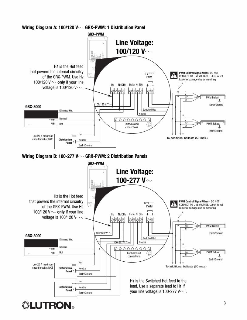
100-127V
220-240V
N2 DL2/DH2 L1/H1 N1 N1 SL1/SH 1 + –
Max 0.3A0-10V
Control Input s Load SwitchedL2/H2
100-277V
EAR TH/GROUNDCONNECTIONS
L2/H
2 10
0-12
0VN
2
DL2/
DH
2
L1/H
1
N1
N1
SL1/
SH1
0-10
Vol
t
NEUTRAL
L2/H
2 22
0-24
0V
N
LUTRO N
3
Wiring Diagram A: 100/120 V GRX-PWM: 1 Distribution Panel
Earth/Ground
GRX-3000
DistributionPanel
PWM Ballast
PWM Ballast
Dimmed Hot
Neutral
Neutral
Neutral
Hot
Switched Hot
HotUse 20 A maximumcircuit breaker/MCB To additional ballasts (50 max.)
GRX-PWM
PWM Control Signal Wires: DO NOTCONNECT TO LINE VOLTAGE. Lutron is notliable for damage due to miswiring.
Earth/Ground
Earth/Ground
Wiring Diagram B: 100-277 V GRX-PWM: 2 Distribution Panels
R
Earth/Groundconnections
100-127V
220-240V
N2 DL2/DH2 L1/H1 N1 N1 SL1/SH 1 + –
Max 0.3A0-10V
Control Inputs Load SwitchedL2/H 2
100-277V
EAR TH/GROUNDCONNECTIONS
L2/H
2 10
0-12
0VN
2
DL2/
DH
2
L1/H
1
N1
N1
SL1/
SH1
0-10
Vol
t
NEUTRA L
L2/H
2 22
0-24
0V
N
LUTRO N
N
Earth/Ground
DistributionPanel
PWM Ballast
PWM Ballast
Dimmed Hot
Neutral
Neutral
Neutral
Hot
Switched Hot
HotUse 20 A maximumcircuit breaker/MCB To additional ballasts (50 max.)
PWM Control Signal Wires - DO NOTCONNECT TO LINE VOLTAGE. Lutron is notliable for damage due to miswiring.
Earth/Ground
Earth/Ground
Earth/Groundconnections
Earth/Ground
DistributionPanel
Neutral
Hot
GRX-3000
GRX-PWM
Line Voltage: 100-277 V
Line Voltage: 100/120 V
100/120 V
100/120 V
100-277 V
H2 is the Hot feed that powers the internal circuitry
of the GRX-PWM. Use H2
100/120 V only if your linevoltage is 100/120 V .
H1 is the Switched Hot feed to theload. Use a separate lead to H1 ifyour line voltage is 100-277 V .
H2 is the Hot feed that powers the internal circuitry
of the GRX-PWM. Use H2
100/120 V only if your linevoltage is 100/120 V .
-+SH1N1
-+SH1N1
H2 N2 DH2
12 VPWM
H1 N1 N1 SH1
H2 N2 DH2
12 VPWM
H1 N1 N1 SH1
-+SH1N1
-+SH1N1
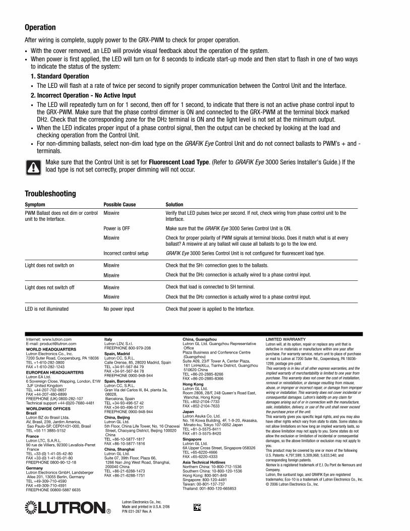
Operation
After wiring is complete, supply power to the GRX-PWM to check for proper operation.
• With the cover removed, an LED will provide visual feedback about the operation of the system.• When power is first applied, the LED will turn on for 8 seconds to indicate start-up mode and then start to flash in one of two ways
to indicate the status of the system:
1. Standard Operation• The LED will flash at a rate of twice per second to signify proper communication between the Control Unit and the Interface.
2. Incorrect Operation - No Active Input• The LED will repeatedly turn on for 1 second, then off for 1 second, to indicate that there is not an active phase control input to
the GRX-PWM. Make sure that the phase control dimmer is ON and connected to the GRX-PWM at the terminal block markedDH2. Check that the corresponding zone for the DH2 terminal is ON and the light level is not set at the minimum output.
• When the LED indicates proper input of a phase control signal, then the output can be checked by looking at the load andchecking operation from the Control Unit.
• For non-dimming ballasts, select non-dim load type on the GRAFIK Eye Control Unit and do not connect ballasts to PWM’s + and -terminals.
Make sure that the Control Unit is set for Fluorescent Load Type. (Refer to GRAFIK Eye 3000 Series Installer's Guide.) If theload type is not set correctly, proper dimming will not occur.
Solution
Verify that LED pulses twice per second. If not, check wiring from phase control unit to theInterface.
Make sure that the GRAFIK Eye 3000 Series Control Unit is ON.
Check for proper polarity of PWM signals at terminal blocks. Does it match what is at everyballast? A miswire at any ballast will cause all ballasts to go to the low end.
GRAFIK Eye 3000 Series Control Unit is not configured for fluorescent load type.
Check that the SH1 connection goes to the ballasts.
Check that the DH2 connection is actually wired to a phase control input.
Check that load is connected to SH terminal.
Check that the DH2 connection is actually wired to a phase control input.
Check that power is applied to the Interface.
Symptom
PWM Ballast does not dim or controlunit to the Interface.
Light does not switch on
Light does not switch off
LED is not illuminated
Possible Cause
Miswire
Power is OFF
Miswire
Incorrect control setup
Miswire
Miswire
Miswire
Miswire
No power input
Troubleshooting
Lutron Electronics Co., Inc.Made and printed in U.S.A. 2/06P/N 031-267 Rev. AR
LIMITED WARRANTYLutron will, at its option, repair or replace any unit that isdefective in materials or manufacture within one year afterpurchase. For warranty service, return unit to place of purchaseor mail to Lutron at 7200 Suter Rd., Coopersburg, PA 18036-1299, postage pre-paid.This warranty is in lieu of all other express warranties, and theimplied warranty of merchantability is limited to one year frompurchase. This warranty does not cover the cost of installation,removal or reinstallation, or damage resulting from misuse,abuse, or improper or incorrect repair, or damage from improperwiring or installation. This warranty does not cover incidental orconsequential damages. Lutron’s liability on any claim fordamages arising out of or in connection with the manufacture,sale, installation, delivery, or use of the unit shall never exceedthe purchase price of the unit.This warranty gives you specific legal rights, and you may alsohave other rights which vary from state to state. Some states donot allow limitations on how long an implied warranty lasts, sothe above limitation may not apply to you. Some states do notallow the exclusion or limitation of incidental or consequentialdamages, so the above limitation or exclusion may not apply toyou.This product may be covered by one or more of the followingU.S. Patents: 4,797,599; 5,309,068; 5,633,540; andcorresponding foreign patents.Nomex is a registered trademark of E.I. Du Pont de Nemours andCompany.Lutron, the sunburst logo, and GRAFIK Eye are registeredtrademarks; Eco-10 is a trademark of Lutron Electronics Co., Inc.© 2006 Lutron Electronics Co., Inc.
Internet: www.lutron.comE-mail: [email protected] HEADQUARTERSLutron Electronics Co., Inc.7200 Suter Road, Coopersburg, PA 18036TEL +1-610-282-3800FAX +1-610-282-1243EUROPEAN HEADQUARTERSLutron EA Ltd.6 Sovereign Close, Wapping, London, E1W3JF United KingdomTEL +44-207-702-0657FAX +44-207-480-6899FREEPHONE (UK) 0800-282-107Technical support +44-(0)20-7680-4481WORLDWIDE OFFICES BrazilLutron BZ do Brasil Ltda.AV, Brasil, 239, Jardim America, Sao Paulo-SP, CEP01431-000, BrasilTEL +55 11 3885-5152FranceLutron LTC, S.A.R.L.90 rue de Villiers, 92300 Levallois-PerretFranceTEL +33-(0) 1-41-05-42-80FAX +33-(0) 1-41-05-01-80FREEPHONE 0800-90-12-18GermanyLutron Electronics GmbH, LandsbergerAllee 201, 13055 Berlin, GermanyTEL +49-309-710-4590FAX +49-309-710-4591FREEPHONE 00800-5887 6635
ItalyLutron LDV, S.r.l.FREEPHONE 800-979-208Spain, MadridLutron CC, S.R.L.Calle Orense, 85, 28020 Madrid, SpainTEL +34-91-567-84 79FAX +34-91-567-84 78FREEPHONE 0900-948-944Spain, BarcelonaLutron CC, S.R.L.Gran Via del Carlos III, 84, planta 3a,08028, Barcelona, SpainTEL +34-93-496-57 42FAX +34-93-496-57 01FREEPHONE 0900-948-944China, BeijingLutron GL Ltd.5th Floor, China Life Tower, No. 16 ChaowaiStreet, Chaoyang District, Beijing 100020ChinaTEL +86-10-5877-1817FAX +86-10-5877-1816China, ShanghaiLutron GL Ltd. Suite 07, 39th Floor, Plaza 66, 1266 Nan Jing West Road, Shanghai,200040 ChinaTEL +86-21-6288-1473FAX +86-21-6288-1751
China, GuangzhouLutron GL Ltd. Guangzhou RepresentativeOfficePlaza Business and Conference Centre(Guangzhou)Suite A09, 23/F Tower A, Center Plaza, 161 LinHeXiLu, Tianhe District, Guangzhou510620 ChinaTEL +86-20-2885-8266FAX +86-20-2885-8366Hong KongLutron GL Ltd.Room 2808, 28/F, 248 Queen's Road East, Wanchai, Hong KongTEL +852-2104-7733FAX +852-2104-7633JapanLutron Asuka Co. Ltd.No. 16 Kowa Building, 4F, 1-9-20, Akasaka, Minato-ku, Tokyo 107-0052 JapanTEL +81-3-5575-8411FAX +81-3-5575-8420SingaporeLutron GL Ltd. 6A Upper Cross Street, Singapore 058326TEL +65-6220-4666FAX +65-6220-4333Asia Technical HotlinesNorthern China: 10-800-712-1536Southern China: 10-800-120-1536Hong Kong: 800-901-849Singapore: 800-120-4491Taiwan: 00-801-137-737Thailand: 001-800-120-665853

Four Mounting HolesDiameter - 0.25 in. (6mm)
Four ScrewsSecure Cover
6.10 in.(155 mm)
3.30 in.(84 mm)
12.50 in.(318 mm)
Wall11.75 in.(298 mm)
4.0 in.(102 mm)
COOPERSBURG, PA 18036 U.S.A.G 2 CB144-317 Rev. 1.9
0-10V INTERFACE CONTROLControl Input:
100-120V, 220-240V 50/60HzSwitched Output: 100-277
GRX-TVI
Incandescent 16A
Fluorescent 5A
Magnetic Low-voltage 16A
Electronic Low-voltage 16A
Neon/Cold Cathode 16A
Motor 1/4 HP@120V1/2 HP@277V
®
ControlGRX-TVI Input Rating
IH2 0.02AIDH2 0.1A
Load Type Switched
Ratings ®
10A
5AX
10A
10A
10A
ControlGRX-TVI Input Rating
IH2 0.02AIDH2 0.1A
Load Type Switched
Ratings ✔ ACN
003 715 277
0-10V Output Rating
Max. 0.3A PELV
0-10V Output Rating
Max. 0.3A Class 2
Switched µ
Installation and Operation InstructionsRead Before InstallingOccupant Copy
GRX-TVI Control InterfacePhase Control to 0-10V
DescriptionThe GRX-TVI provides 0-10V control and ballast switching capabili-ties in one enclosure. The GRX-TVI gives GRAFIK Eye 3000 SeriesControl Units the ability to control any 0-10V ballasts powered by100V-277V (ballast must provide 0-10V sourcing of current)and provides switching relays that can handle the in-rush current for acircuit of ballasts. The GRX-TVI gives a GRAFIK Eye 3000 SeriesControl Unit the ability to both dim and switch electronic ballasts,such as Lutron's Eco-10™ (TVE models). The GRX-TVI can also beused to switch any of the load types listed below.
Note: When using a Control Unit, a GRX-TVI is required for each 0-10Vfluorescent zone. (A 3-zone Control Unit with two fluorescent zonesand one incandescent zone is shown as an example.)
MountingFind a suitable location for mounting.� Decide on the proper location for the GRX-TVI (NEMA Type 1
enclosure, indoor use only). See System Wiring Layout below.� The environment where the GRX-TVI is placed must have an
ambient temperature range of 32—104 °F (0—40 °C).� Mount the enclosure vertically on a wall (screws not provided). See
Mounting Diagram below.� Mounting method must be able to support weight and forces
applied during installation.� Iinternal relays will click while in operation — mount where
audible noise is acceptable.
System Wiring Layout
Mounting Diagram
Product Specifications
Four Mounting HolesDiameter: 0.25 in. (6 mm)
Four Screws Secure Cover
12.5 in.(318 mm)
3.30 in.(84 mm)
6.10 in.(155 mm)
LUTRON LUTRON
LUTRON
0-10V Control Fluorescent Zone/Load 1
0-10V Control Fluorescent Zone/Load 10-10V Ballast
Power fromDistribution
Panel
GRX-TVI
GRX-TVI
Ballast
Switched Fluorescent Zone/Load 2
Incandescent Zone/Load 3
Control Unit Class 2/PELV Accessory Controls
0-10V Ballast
COOPERSBURG, PA 18036 U.S.A.G 2 CB144-317 Rev. 1.9
0-10V INTERFACE CONTROLControl Input:
100-120V, 220-240V 50/60HzSwitched Output: 100-277
GRX-TVI
Incandescent 16A
Fluorescent 5A
Magnetic Low-voltage 16A
Electronic Low-voltage 16A
Neon/Cold Cathode 16A
Motor 1/4 HP@120V1/2 HP@277V
®
ControlGRX-TVI Input Rating
IH2 0.02AIDH2 0.1A
Load Type Switched
Ratings ®
10A
5AX
10A
10A
10A
ControlGRX-TVI Input Rating
IH2 0.02AIDH2 0.1A
Load Type Switched
Ratings ✔ ACN
003 715 277
0-10V Output Rating
Max. 0.3A PELV
0-10V Output Rating
Max. 0.3A Class 2
Switched µ
4.0 in.(102 mm)
11.75 in.(298 mm) WALL
100-127V/200-277V230V (CE)
FEATURES .....................Provides a Class 2/PELV isolated 0-10V output signal thatconforms to EN60929 and IEC60929Accepts a constant-gate drive fluorescent signal (100-127V,220-240V, 50/60Hz)
INPUT POWER RATING ................100-127/220-240V, 50/60HzH2/L2 TERMINAL .........................20mAINPUT RATING
DH2/DL2 TERMINAL .....................100mAINPUT RATING
0-10V OUTPUT RATING ...............10µA-300mA - Sinks current only (maximum 150ballasts)
Source/Load Type
Fluorescent:Lutron Eco-10T
(TVE Series)Electronic Capacitive
Non-DimOther Manufacturer’s 0-10V
Ballasts (0-10V source only)Incandescent
Low-Voltage
Metal Halide
Neon/Cold Cathode
16A
16A
16A
16A
16A
16A
16A
—
10A
10A
10A
10A
10A
10A
Motors 1/4HP @ 100-120V1/2HP @ 200-277V1/2HP @ 230V CE
TERMINALS Two #12-20AWG (0.5-2.5 mm2) conductors per terminal.
MOUNTING NEMA Type 1 enclosure, indoor use only.
ENVIRONMENTAL 32—104 ˚F (0—40 ˚C).
WEIGHT 4.25 lb. (2kg)
100-127V and 220-240V/CE
EnglishItaliano

2
220-240V/CE Control InterfaceImportant Installation Information� Install in accordance with all national and local electrical codes.� Check for short circuited loads during new installations before wiring the GRX-TVI.
Caution: Multiple feeds may enter this enclosure. Locate and lock each feed circuit breaker/MCB in the OFF positionbefore wiring the Interface.
� Proper short circuit and overload protection must be provided at the distribution panel. You can use up to a 20A (16A for CE)maximum circuit breaker/MCB or equivalent (tripping curve C according to IEC 898/EN60898 is recommended) with adequateshort circuit breaking capacity for your installation.
� Terminal blocks are rated for two #12-22 AWG (0.5-2.5 mm2) wires per terminal.� Strip 3/8 in. (10 mm) of insulation from wires.� Wiring Diagram A shows a GRX-TVI wired from one distribution panel. If the
power requirement of the complete system is less than an MCB/circuitbreaker rating, one feed can be jumpered inside the enclosure (as shown).
� Wiring Diagram B shows a GRX-TVI wired from two separate distribution panels that may be different phases or voltages.� Use the internal terminal block label to see where to land wires.
— The label shows two separate Hot/Live terminals (L1/H1 & L2/H2).L1/H1 is the Hot/Live feed to power the lighting load.L2/H2 is the Hot/Live feed that powers internal circuitry of the GRX-TVI.L2/H2 has a 100-127V connection and a 220-240V connection - useonly the one corresponding to line voltage for your application.Note 1: Not all terminal blocks receive a connection.Note 2: The power feed to the Control Unit and L2/H2 of the GRX-
TVI must be the same phase!Class 2/PELV, 0-10V wiring from a ballast to the GRX-TVI-CE must be separated from the power wiring. Enter theClass 2/PELV wires through the knockout adjacent to the 0-10V terminal blocks. The Nomex® barrier ensuresseparation and is flexible to allow access to the terminals. The barrier must be in place when installation iscomplete.
GRX-TVI Internal Terminal Block Label Definitions
Use only one input according to Input Voltage:L2/H2 240V Power input for GRX-TVI control (line/mains voltage must be 220-240V)L2/H2 127V Power input for GRX-TVI control (line/mains voltage must be 100-127V)N2 Neutral for GRX-TVI controlDL2/DH GRAFIK Eye 3000 Series Control Unit Lighting Zone connection (Phase Control Input to GRX-TVI)L1/H1 Power input for lighting loadN1 Neutral for lighting load (2 terminals provided and internally tied together — one for input neutral and one
for load neutral)SL1/SH1 Switched output to power lighting load+ - 0-10V control signal wires (ballast must provide a 0-10V source only)
10mm(3/8in.)
L2/
H2
100-
127V
N2
DL2
/DH
2
L1/
H1
100-
277V
N1
N1
SL1
/SH
1
0-10
Vol
t
L2/H
2 22
0-24
0V/C
E
Use only ifyour
line/mainsvoltage is
220-240V.
Use only if your line/mains voltage is120-127V.
Input from distributionpanel.
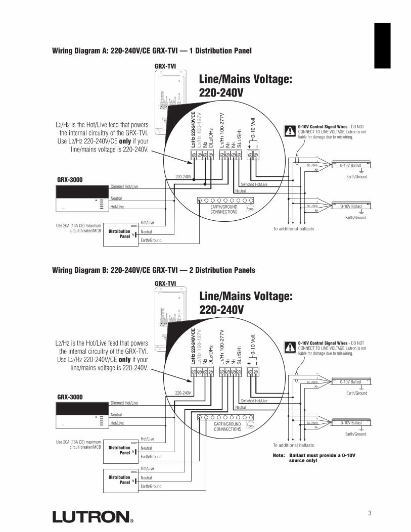
100-127V
220-240V
N2 DL2/DH2 L1/H1 N1 N1 SL1/SH1 + –
Max 0.3A0-10V
Control Inputs Load SwitchedL2/H2
100-277V
EARTH/GROUNDCONNECTIONS
L2/H
2 10
0-12
0VN
2
DL2
/DH
2
L1/H
1
N1
N1
SL1
/SH
1
0-10
Vol
t
NEUTRAL
L2/H
2 22
0-24
0V
L2/H
2 10
0-12
7VN
2
DL2
/DH
2
L1/H
110
0-27
7VN
1
N1
SL1
/SH
1
0-10
Vol
t
L2/H
2 22
0-24
0V/C
E
–+
SL1/SH1
N1
–
+SL1/SH1
N1
N
LUTRON
3
Wiring Diagram A: 220-240V/CE GRX-TVI — 1 Distribution Panel
Earth/Ground
GRX-3000
DistributionPanel
0-10V Ballast
0-10V Ballast
Dimmed Hot/Live
Neutral
Neutral
Neutral
Hot/Live
Switched Hot/Live
Hot/LiveUse 20A (16A CE) maximum
circuit breaker/MCB To additional ballasts
GRX-TVI
0-10V Control Signal Wires - DO NOTCONNECT TO LINE VOLTAGE. Lutron is notliable for damage due to miswiring.
Earth/Ground
Earth/Ground
Wiring Diagram B: 220-240V/CE GRX-TVI — 2 Distribution Panels
EARTH/GROUNDCONNNECTIONS
100-127V
220-240V
N2 DL2/DH2 L1/H1 N1 N1 SL1/SH1 + –
Max 0.3A0-10V
Control Inputs Load SwitchedL2/H2
100-277V
EARTH/GROUNDCONNECTIONS
L2/H
2 10
0-12
0VN
2
DL2
/DH
2
L1/H
1
N1
N1
SL1
/SH
1
0-10
Vol
t
NEUTRAL
L2/H
2 22
0-24
0V
L2/H
2 10
0-12
7VN
2
DL2
/DH
2
L1/H
110
0-27
7VN
1
N1
SL1
/SH
1
0-10
Vol
t
L2/H
2 22
0-24
0V/C
E
–+
SL1/SH1
N1
–
+SL1/SH1
N1
N
LUTRON
N
Earth/Ground
DistributionPanel
0-10V Ballast
0-10V Ballast
Dimmed Hot/Live
Neutral
Neutral
Neutral
Hot/Live
Switched Hot/Live
Hot/LiveUse 20A (16A CE) maximum
circuit breaker/MCB To additional ballasts
Note: Ballast must provide a 0-10Vsource only!
0-10V Control Signal Wires - DO NOTCONNECT TO LINE VOLTAGE. Lutron is notliable for damage due to miswiring.
Earth/Ground
Earth/Ground
EARTH/GROUNDCONNNECTIONS
Earth/Ground
DistributionPanel
Neutral
Hot/Live
GRX-3000
GRX-TVI
Line/Mains Voltage: 220-240V
Line/Mains Voltage: 220-240V
220-240V
220-240V
L2/H2 is the Hot/Live feed that powersthe internal circuitry of the GRX-TVI.
Use L2/H2 220-240V/CE only if yourline/mains voltage is 220-240V.
L2/H2 is the Hot/Live feed that powersthe internal circuitry of the GRX-TVI.
Use L2/H2 220-240V/CE only if yourline/mains voltage is 220-240V.

4
100-127V Control InterfaceImportant Installation Information� Install in accordance with all national and local electrical codes.� Check for short circuited loads during new installations before wiring the GRX-TVI.
Caution: Multiple feeds may enter this enclosure. Locate and lock each feed circuit breaker/MCB in the OFF positionbefore wiring the Interface.
� Proper short circuit and overload protection must be provided at the distribution panel. You can use up to a 20A (16A for CE)maximum circuit breaker/MCB or equivalent (tripping curve C according to IEC 898/EN60898 is recommended) with adequateshort circuit breaking capacity for your installation.
� Terminal blocks are rated for two #12-22 AWG (0.5-2.5 mm2) wires per terminal.� Strip 3/8 in. (10 mm) of insulation from wires.� Wiring Diagram C shows a GRX-TVI wired from one distribution panel. If the
power requirement of the complete system is less than an MCB/circuitbreaker rating, one feed can be jumpered inside the enclosure (as shown).
� Wiring Diagram D shows a GRX-TVI wired from two separate distribution panels that may be different phases or voltages.� Use the internal terminal block label to see where to land wires.
— The label shows two separate Hot/Live terminals (L1/H1 & L2/H2).L1/H1 is the Hot/Live feed to power the lighting load.L2/H2 is the Hot/Live feed that powers internal circuitry of the GRX-TVI.L2/H2 has a 100-127V connection and a 220-240V connection - useonly the one corresponding to line voltage for your application.Note 1: Not all terminal blocks receive a connection.Note 2: The power feed to the Control Unit and L2/H2 of the GRX-
TVI must be the same phase!Class 2/PELV, 0-10V wiring from a ballast to the GRX-TVI-CE must be separated from the power wiring. Enter theClass 2/PELV wires through the knockout adjacent to the 0-10V terminal blocks. The Nomex® barrier ensuresseparation and is flexible to allow access to the terminals. The barrier must be in place when installation iscomplete.
GRX-TVI Internal Terminal Block Label Definitions
Use only one input according to Input Voltage:L2/H2 240V Power input for GRX-TVI control (line/mains voltage must be 220-240V)L2/H2 127V Power input for GRX-TVI control (line/mains voltage must be 100-127V)N2 Neutral for GRX-TVI controlDL2/DH GRAFIK Eye 3000 Series Control Unit Lighting Zone connection (Phase Control Input to GRX-TVI)L1/H1 Power input for lighting loadN1 Neutral for lighting load (2 terminals provided and internally tied together — one for input neutral and one
for load neutral)SL1/SH1 Switched output to power lighting load+ - 0-10V control signal wires (ballast must provide a 0-10V source only)
10mm(3/8in.)
L2/
H2
100-
127V
N2
DL2
/DH
2
L1/
H1
100-
277V
N1
N1
SL1
/SH
1
0-10
Vol
t
L2/H
2 22
0-24
0V/C
E
Use only ifyour
line/mainsvoltage is
220-240V.
Use only if your line/mains voltage is120-127V.
Input from distributionpanel.

5
Wiring Diagram C: 100-127V GRX-TVI — 1 Distribution Panel
100-127V
220-240V
N2 DL2/DH2 L1/H1 N1 N1 SL1/SH1 + –
Max 0.3A0-10V
Control Inputs Load SwitchedL2/H2
100-277V
EARTH/GROUNDCONNECTIONS
L2/H
2 10
0-12
0VN
2
DL2
/DH
2
L1/H
1
N1
N1
SL1
/SH
1
0-10
Vol
t
NEUTRAL
L2/H
2 22
0-24
0V
L2/
H2
100-
127V
N2
DL2
/DH
2
L1/H
110
0-27
7VN
1
N1
SL1
/SH
1
0-10
Vol
t
L2/H
2 22
0-24
0V/C
E
–+
SL1/SH1
N1
–
+SL1/SH1
N1
N
LUTRON
Earth/Ground
GRX-3000
DistributionPanel
0-10V Ballast
0-10V Ballast
Dimmed Hot/Live
Neutral
Neutral
Neutral
Hot/Live
Switched Hot/Live
Hot/LiveUse 20A (16A CE) maximum
circuit breaker/MCB To additional ballasts
Note: Ballast must provide a 0-10Vsource only!
GRX-TVI
0-10V Control Signal Wires - DO NOTCONNECT TO LINE VOLTAGE. Lutron is notliable for damage due to miswiring.
Earth/Ground
Earth/Ground
Wiring Diagram D: 100-127V GRX-TVI — 2 Distribution Panels
EARTH/GROUNDCONNNECTIONS
100-127V
220-240V
N2 DL2/DH2 L1/H1 N1 N1 SL1/SH1 + –
Max 0.3A0-10V
Control Inputs Load SwitchedL2/H2
100-277V
EARTH/GROUNDCONNECTIONS
L2/H
2 10
0-12
0VN
2
DL2
/DH
2
L1/H
1
N1
N1
SL1
/SH
1
0-10
Vol
t
NEUTRAL
L2/H
2 22
0-24
0V
L2/
H2
100-
127V
N2
DL2
/DH
2
L1/H
110
0-27
7VN
1
N1
SL1
/SH
1
0-10
Vol
t
L2/H
2 22
0-24
0V/C
E
–+
SL1/SH1
N1
–
+SL1/SH1
N1
N
LUTRON
N
Earth/Ground
DistributionPanel
0-10V Ballast
0-10V Ballast
Dimmed Hot/Live
Neutral
Neutral
Neutral
Hot/Live
Switched Hot/Live
Hot/LiveUse 20A (16A CE) maximum
circuit breaker/MCB To additional ballasts
0-10V Control Signal Wires - DO NOTCONNECT TO LINE VOLTAGE. Lutron is notliable for damage due to miswiring.
Earth/Ground
Earth/Ground
EARTH/GROUNDCONNNECTIONS
Earth/Ground
DistributionPanel
Neutral
Hot/Live
GRX-3000
GRX-TVI
120-127V
120-127V
Line/Mains Voltage: 120-127V
Line/Mains Voltage: 120-127V
L2/H2 is the Hot/Live feed that powersthe internal circuitry of the GRX-TVI.
Use L2/H2 100-127V only if yourline/mains voltage is 120-127V.
L2/H2 is the Hot/Live feed that powersthe internal circuitry of the GRX-TVI.
Use L2/H2 100-127V only if yourline/mains voltage is 120-127V.
Chinese

OperationAfter wiring is complete, supply power to the GRX-TVI to check for proper operation.■ With the cover removed, an LED will provide visual feedback about the operation of the system.■ When power is first applied, the LED will turn on for 8 seconds to indicate start-up mode and then start to flash in one of two ways to
indicate the status of the system:1. Standard Operation■ The LED will flash at a rate of twice per second to signify proper communication between the Control Unit and the Interface.2. Incorrect Operation - No Active Input■ The LED will repeatedly turn on for 1 second then off for 1 second to indicate that there is not an active phase control input to the GRX-
TVI. Make sure that the phase control dimmer is ON and connected to the GRX-TVI at the terminal block marked DL2/DH2. Check thatthe corresponding zone for the DL2/DH2 terminal is ON and the light level is not set at the minimum output.
■ When the LED indicates proper input of a phase control signal, then the output can be checked by looking at the load and checking operationfrom the Control Unit.
■ For non-dimming ballasts, select non-dim load type on the GRAFIK Eye Control Unit and do not connect ballasts to 0-10V terminals.
Make sure that the Control Unit is set for Fluorescent Load Type. (Refer to GRAFIK Eye 3000 Series Installer's Guide.) If the loadtype is not set correctly, proper dimming will not occur.
Lutron Electronics Co., Inc.Made and printed in U.S.A. 8/03P/N 032-119 Rev. B
FRANCELutron LTCInternational +33-1-44-70-72-00Int’l Fax: +33-1-44-70-00-19
ASIAN HEADQUARTERSLutron Asuka Corporation (Japan)Tel:(03)-5575-8411;International (03)-5575-8411Fax: +(03) -5575-8420;International +81-3-5575-8420
HONG KONG SALES OFFICELutron GL (Hong Kong)Tel: 2104-7733;International +852-2104-7733Fax: 2104-7633;International +852-2104-7633
SINGAPORELutron GL (Singapore)Tel: +65-6220-4666Fax: +65-6220-4333
Internet: www.lutron.comE-mail: [email protected]
WORLD HEADQUARTERSLutron Electronics Co. Inc.,TOLL FREE: (800) 523-9466(U.S.A., Canada, Caribbean)Tel: (610) 282-3800;International +1- 610-282-3800Fax: (610) 282-1243;International +1-610-282-1243
EUROPEAN HEADQUARTERSLutron EA Ltd.,Tel: (207) 702-0657;International +44-207-702-0657Fax: (207) 480-6899;International +44-207-480-6899
GERMANYLutron Electronics GmbHTel: (309) 710-4590;International +49-309-710-4590Fax: (309) 710-4591;International +49-309-710-4591
LIMITED WARRANTYLutron will, at its option, repair or replace any unit that is defective in materials ormanufacture within one year after purchase. For warranty service, return unit to place ofpurchase or mail to Lutron at 7200 Suter Rd., Coopersburg, PA 18036-1299, postage pre-paid.This warranty is in lieu of all other express warranties, and the impliedwarranty of merchantability is limited to one year from purchase. Thiswarranty does not cover the cost of installation, removal or reinstallation, ordamage resulting from misuse, abuse, or improper or incorrect repair, ordamage from improper wiring or installation. This warranty does not coverincidental or consequential damages. Lutron’s liability on any claim fordamages arising out of or in connection with the manufacture, sale,installation, delivery, or use of the unit shall never exceed the purchase priceof the unit.This warranty gives you specific legal rights, and you may also have other rights which varyfrom state to state. Some states do not allow limitations on how long an implied warrantylasts, so the above limitation may not apply to you. Some states do not allow the exclusion orlimitation of incidental or consequential damages, so the above limitation or exclusion maynot apply to you. Nomex is a registered trademark of E.I. Du Pont de Nemours and Company.Lutron and GRAFIK Eye are registered trademarks; Eco-10 is a trademark of LutronElectronics Co., Inc.© 2003 Lutron Electronics Co., Inc.
Solution
Verify that LED pulses twice per second. If not, check wiring from phase control unit to the Interface.
Make sure that the GRAFIK Eye 3000 Series Control Unit is ON.
Check for proper polarity of 0-10V signals at terminal blocks. Does it match what is at every ballast? Amiswire at any ballast will cause all ballasts to go to the low end.
GRAFIK Eye 3000 Series Control Unit is not configured for fluorescent load type.
Check that the SL1/SH1 connection goes to the ballasts.
Check that the DL2/DH2 connection is actually wired to a phase control input.
Load is not connected to SH (SL) terminal.
Check that the DL2/DH2 connection is actually wired to a phase control input.
Check that power is applied to the Interface.
Symptom
0-10V Ballast does not dim or controlunit to the Interface.
Light does not switch on
Light does not switch off
LED is not illuminated
Possible Cause
Miswire
Power is OFF
Miswire
Incorrect Control Setup
Miswire
Miswire
Miswire
Miswire
No Power Input
Troubleshooting
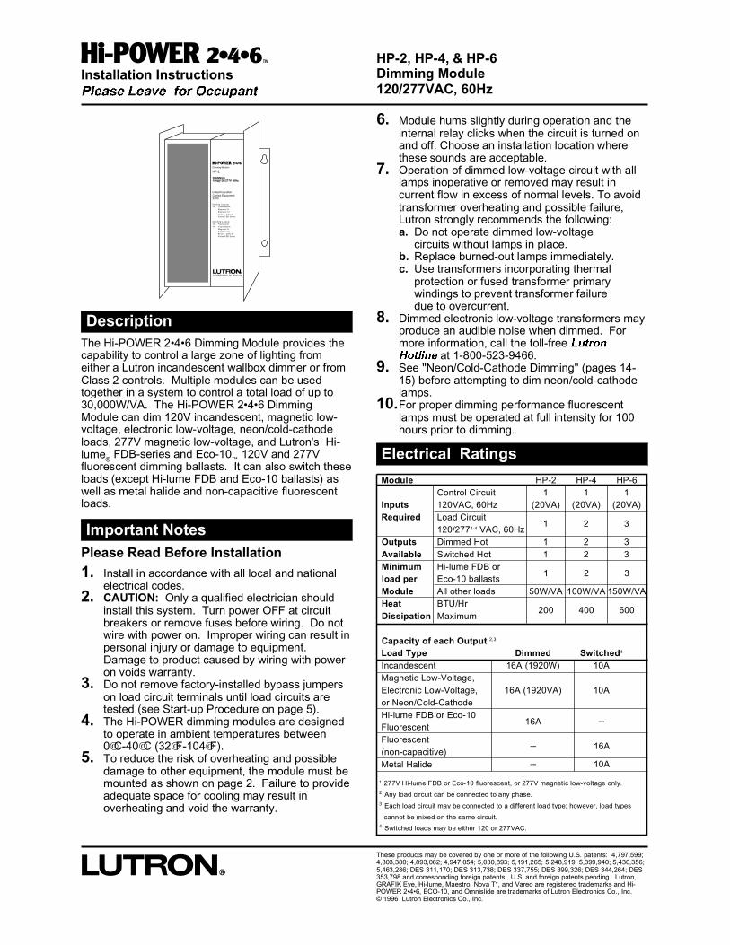
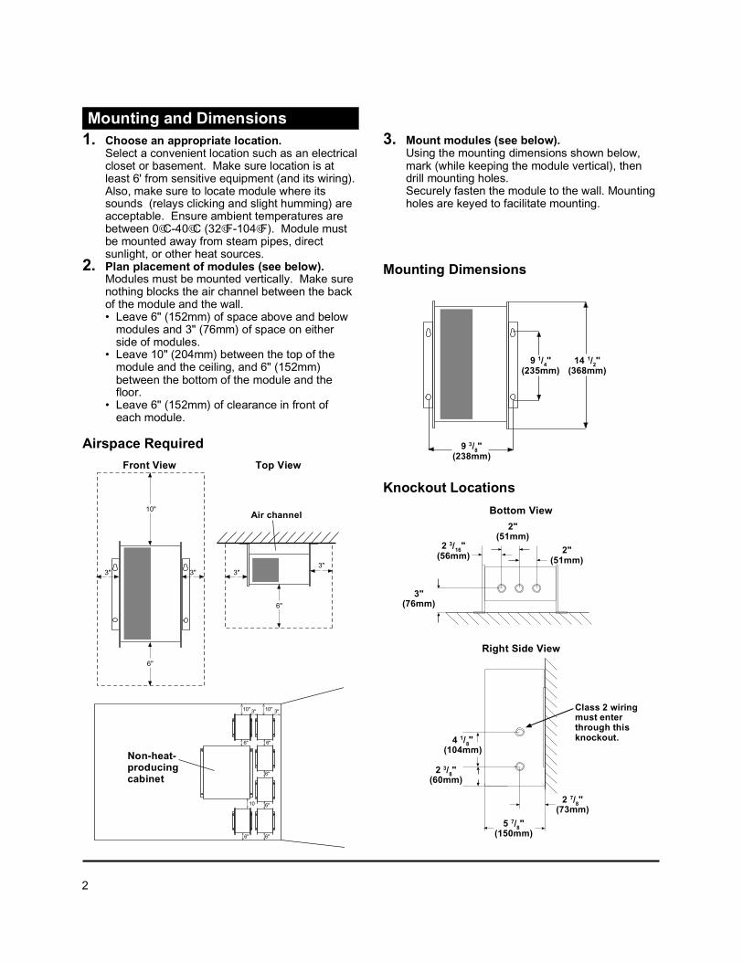
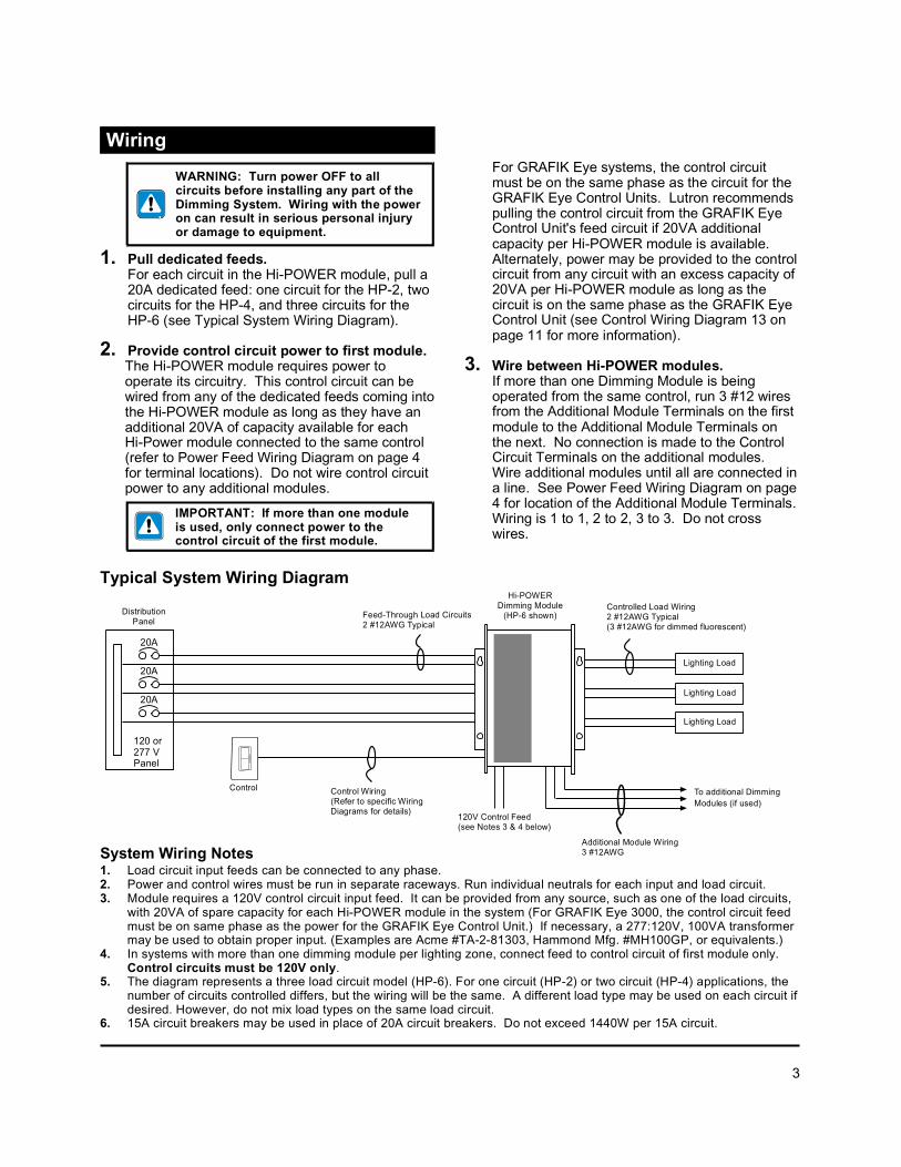
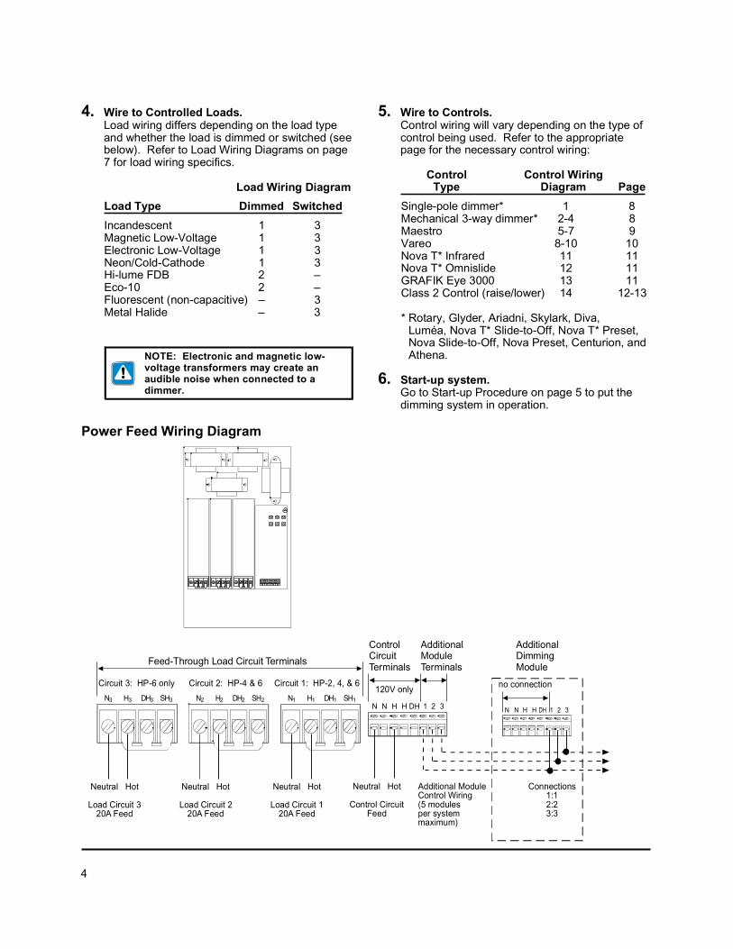


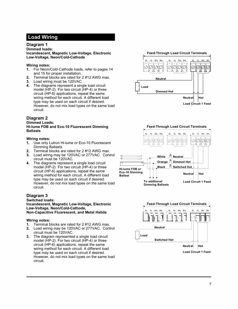
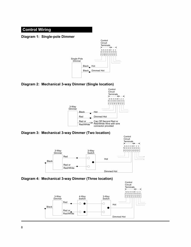
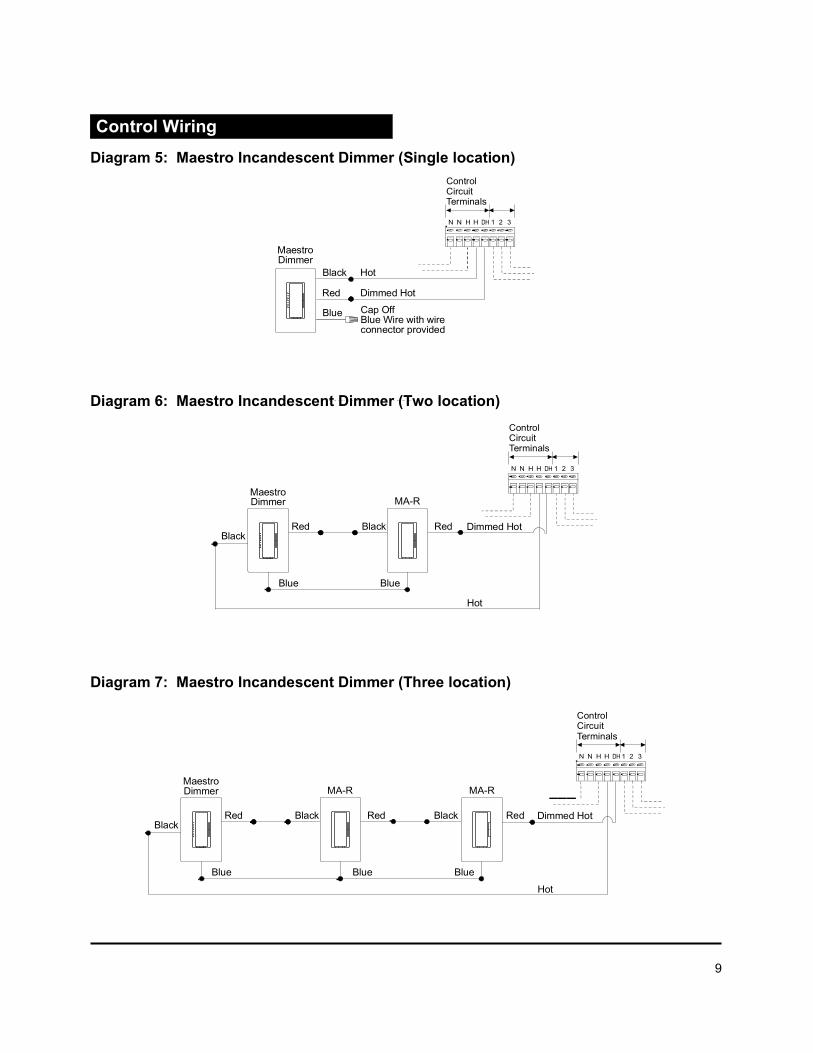
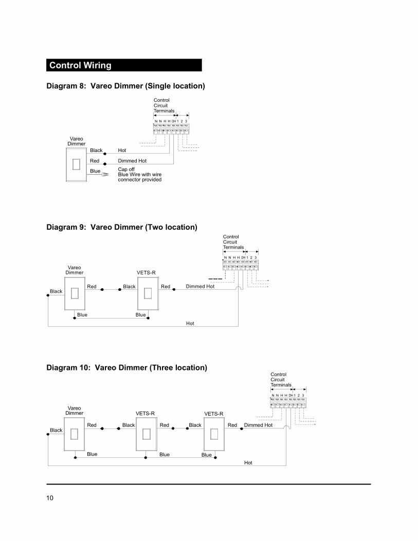

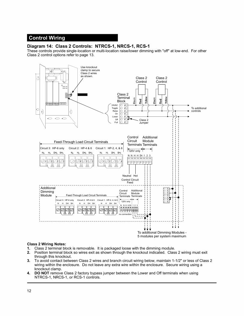


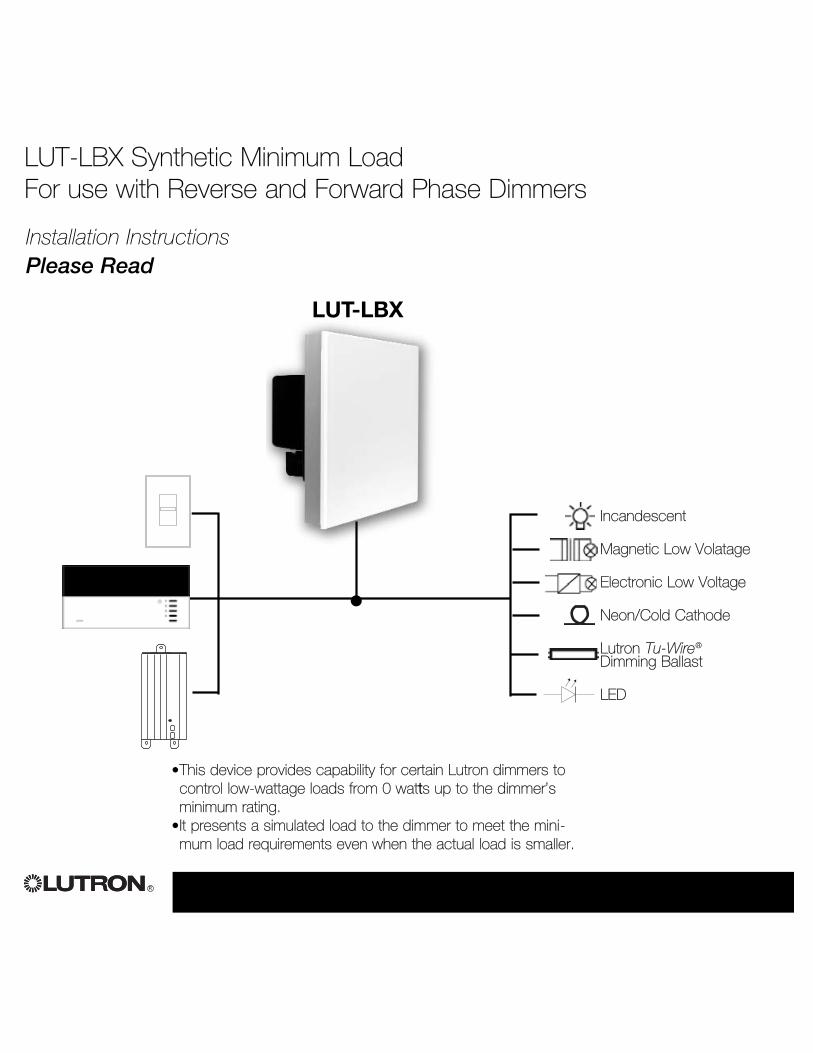
LUT-LBX Synthetic Minimum Load For use with Reverse and Forward Phase Dimmers
R
Incandescent
Magnetic Low Volatage
Electronic Low Voltage
Neon/Cold Cathode
Lutron Tu-Wire®
Dimming Ballast
LED
•This device provides capability for certain Lutron dimmers tocontrol low-wattage loads from 0 wattts up to the dimmer’sminimum rating.
•It presents a simulated load to the dimmer to meet the mini-mum load requirements even when the actual load is smaller.
Installation InstructionsPlease Read
LUT-LBX
•
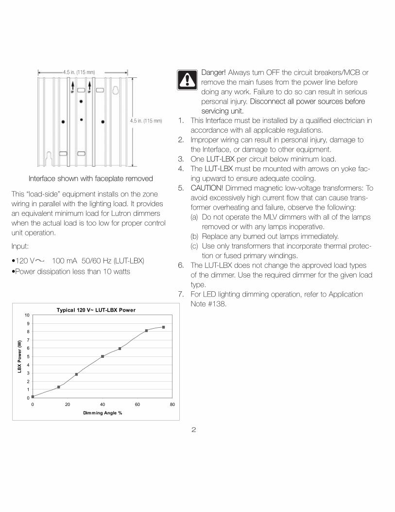
Interface shown with faceplate removed
2
4.5 in. (115 mm)
4.5 in. (115 mm)
Danger! Always turn OFF the circuit breakers/MCB orremove the main fuses from the power line beforedoing any work. Failure to do so can result in seriouspersonal injury. Disconnect all power sources beforeservicing unit.
This “load-side” equipment installs on the zonewiring in parallel with the lighting load. It providesan equivalent minimum load for Lutron dimmerswhen the actual load is too low for proper controlunit operation.
Input:
•120 V 100 mA 50/60 Hz (LUT-LBX)
•Power dissipation less than 10 watts
1. This Interface must be installed by a qualified electrician inaccordance with all applicable regulations.
2. Improper wiring can result in personal injury, damage tothe Interface, or damage to other equipment.
3. One LUT-LBX per circuit below minimum load.4. The LUT-LBX must be mounted with arrows on yoke fac-
ing upward to ensure adequate cooling.5. CAUTION! Dimmed magnetic low-voltage transformers: To
avoid excessively high current flow that can cause trans-former overheating and failure, observe the following:(a) Do not operate the MLV dimmers with all of the lamps
removed or with any lamps inoperative.(b) Replace any burned out lamps immediately.(c) Use only transformers that incorporate thermal protec-
tion or fused primary windings.6. The LUT-LBX does not change the approved load types
of the dimmer. Use the required dimmer for the given loadtype.
7. For LED lighting dimming operation, refer to ApplicationNote #138.
Typical 120 V~ LUT-LBX Power
0
1
2
3
4
5
6
7
8
9
10
0 20 40 60 80
Dimming Angle %
LB
X P
ow
er
(W)

■ Turn power Off.■ Connect standard switch between Hot/Live lead
and the load wire to test circuit.■ Turn power On and check for short or open circuits.
3
Test load for short circuits
Installation Instructions
1. Turn power Off to the Control Unit.2. Mount standard U.S. 2-gang wallbox (available from
Lutron, P/N 241-496); 3 1/2 in. (89 mm) deep isstrongly recommended, 2 3/4 in. (68 mm) mini-mum. Allow at least 4 1/2 in. (110 mm) clearanceabove/below Interfaces to ensure proper heat dissi-pation.
3. Strip 1/2 in. (12 mm) insulation from all wires inwallbox and wire as shown. All connections aremade using #12 AWG to #16 AWG (2.5 - 1 mm2)wire. Power terminals can accept up to two#12 AWG (2.5 mm2) wires. The recommendedinstallation torque is 9.0 in.●lbs. (1.0 N●m) for linevoltage connections.
Single-Zone Wiring
* Wallbox may be recess mounted or surface mounted.If mounting Interface in a panel, please refer to PanelMounting section for important information.
Hot/LiveSwitch
Load
1/2 in. (12 mm)
NEUTRAL
EARTH/GROUND
DIMMED HOT/LIVE
Hot/Live Dimmed Hot/Live
Low-WattageLoad
Neutral(if neces-sary)
120 VLUT-LBX
Dimmer Circuit
NEUTRAL
EARTH/GROUND
DIMMED HOT/LIVE
Hot/Live Dimmed Hot/Live, Zone 1
Low-WattageLoad
Neutral(if neces-sary)
Dimmer Circuit
Dimmed Hot/Live Zone 2
Dual-Zone Wiring
Neutral
Neutral LUT-LBX
LUT-LBX
120 VLUT-LBX
Neutral
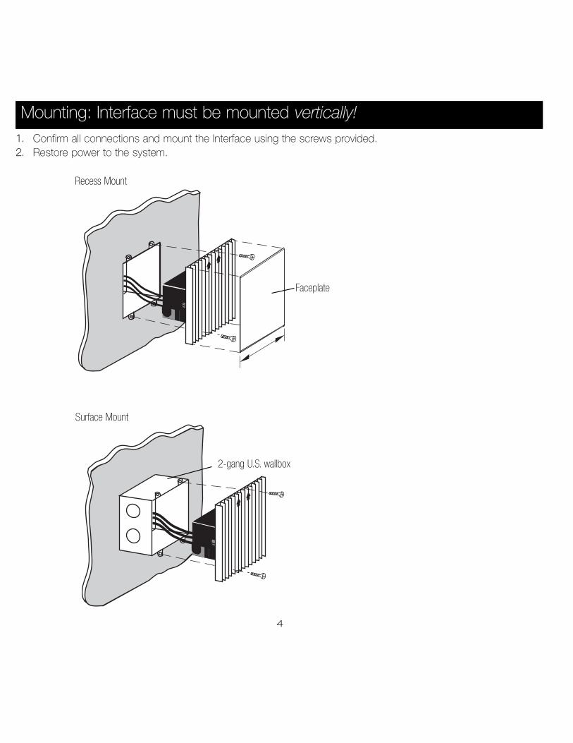
4
1. Confirm all connections and mount the Interface using the screws provided.2. Restore power to the system.
Mounting: Interface must be mounted vertically!
2-gang U.S. wallbox
Faceplate
Recess Mount
Surface Mount
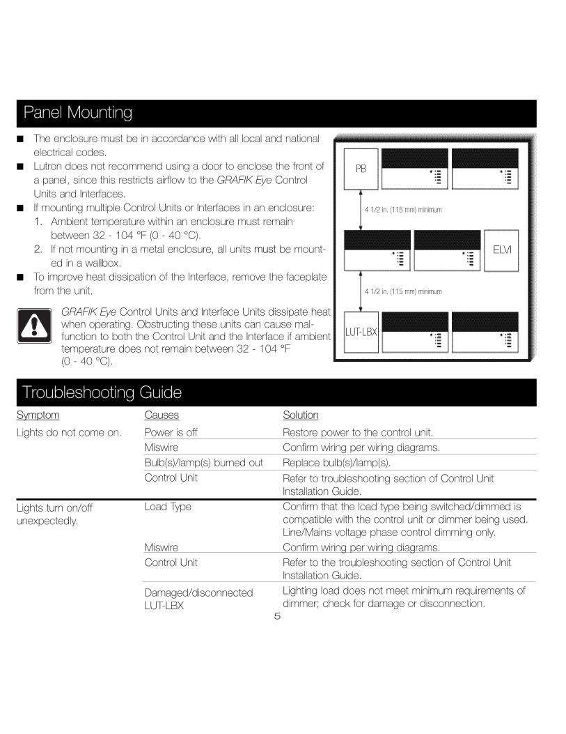
Symptom
Lights do not come on.
Lights turn on/offunexpectedly.
Troubleshooting Guide
PB
ELVI
LUT-LBX
4 1/2 in. (115 mm) minimum
4 1/2 in. (115 mm) minimum
Panel Mounting
■ The enclosure must be in accordance with all local and nationalelectrical codes.
■ Lutron does not recommend using a door to enclose the front ofa panel, since this restricts airflow to the GRAFIK Eye ControlUnits and Interfaces.
■ If mounting multiple Control Units or Interfaces in an enclosure:1. Ambient temperature within an enclosure must remain
between 32 - 104 °F (0 - 40 °C).2. If not mounting in a metal enclosure, all units must be mount-
ed in a wallbox.■ To improve heat dissipation of the Interface, remove the faceplate
from the unit.
GRAFIK Eye Control Units and Interface Units dissipate heatwhen operating. Obstructing these units can cause mal-function to both the Control Unit and the Interface if ambienttemperature does not remain between 32 - 104 °F (0 - 40 °C).
Causes
Power is offMiswireBulb(s)/lamp(s) burned outControl Unit
Load Type
MiswireControl Unit
Damaged/disconnectedLUT-LBX
Solution
Restore power to the control unit.Confirm wiring per wiring diagrams.Replace bulb(s)/lamp(s).
Refer to troubleshooting section of Control UnitInstallation Guide.Confirm that the load type being switched/dimmed iscompatible with the control unit or dimmer being used.Line/Mains voltage phase control dimming only.Confirm wiring per wiring diagrams.Refer to the troubleshooting section of Control UnitInstallation Guide.Lighting load does not meet minimum requirements ofdimmer; check for damage or disconnection.
5

R
Lutron Electronics Co., Inc.Made and printed in U.S.A.P/N 030-852 Rev. A 01/07
Lutron Electronics Co., Inc.One Year Limited Warranty
For a period of one year from the date of purchase, and subject to the exclusions and restrictions described below, Lutron warrants each new unit to befree from manufacturing defects. Lutron will, at its option, either repair the defective unit or issue a credit equal to the purchase price of the defective unit to theCustomer against the purchase price of comparable replacement part purchased from Lutron. Replacements for the unit provided by Lutron or, at its sole discre-tion, an approved vendor may be new, used, repaired, reconditioned, and/or made by a different manufacturer.
If the unit is commissioned by Lutron or a Lutron approved third party as part of a Lutron commissioned lighting control system, the term of this warrantywill be extended, and any credits against the cost of replacement parts will be prorated, in accordance with the warranty issued with the commissioned system,except that the term of the unit's warranty term will be measured from the date of its commissioning.EXCLUSIONS AND RESTRICTIONSThis Warranty does not cover, and Lutron and its suppliers are not responsible for:1. Damage, malfunction or inoperability diagnosed by Lutron or a Lutron approved third party as caused by normal wear and tear, abuse, misuse, incorrect
installation, neglect, accident, interference or environmental factors, such as (a) use of incorrect line voltages, fuses or circuit breakers; (b) failure to install,maintain and operate the unit pursuant to the operating instructions provided by Lutron and the applicable provisions of the National Electrical Code and ofthe Safety Standards of Underwriter's Laboratories; (c) use of incompatible devices or accessories; (d) improper or insufficient ventilation; (e) unauthorizedrepairs or adjustments; (f) vandalism; or (g) an act of God, such as fire, lightning, flooding, tornado, earthquake, hurricane or other problems beyond Lutron'scontrol.
2. On-site labor costs to diagnose issues with, and to remove, repair, replace, adjust, reinstall and/or reprogram the unit or any of its components.3. Equipment and parts external to the unit, including those sold or supplied by Lutron (which may be covered by a separate warranty).4. The cost of repairing or replacing other property that is damaged when the unit does not work properly, even if the damage was caused by the unit.
EXCEPT AS EXPRESSLY PROVIDED IN THIS WARRANTY, THERE ARE NO EXPRESS OR IMPLIED WARRANTIES OF ANY TYPE, INCLUDING ANYIMPLIED WARRANTIES OF FITNESS FOR A PARTICULAR PURPOSE OR MERCHANTABILITY. LUTRON DOES NOT WARRANT THAT THE UNIT WILL OPER-ATE WITHOUT INTERRUPTION OR BE ERROR FREE.
NO LUTRON AGENT, EMPLOYEE OR REPRESENTATIVE HAS ANY AUTHORITY TO BIND LUTRON TO ANY AFFIRMATION, REPRESENTATION OR WAR-RANTY CONCERNING THE UNIT. UNLESS AN AFFIRMATION, REPRESENTATION OR WARRANTY MADE BY AN AGENT, EMPLOYEE OR REPRESENTATIVE ISSPECIFICALLY INCLUDED HEREIN, OR IN STANDARD PRINTED MATERIALS PROVIDED BY LUTRON, IT DOES NOT FORM A PART OF THE BASIS OF ANYBARGAIN BETWEEN LUTRON AND CUSTOMER AND WILL NOT IN ANY WAY BE ENFORCEABLE BY CUSTOMER.
IN NO EVENT WILL LUTRON OR ANY OTHER PARTY BE LIABLE FOR EXEMPLARY, CONSEQUENTIAL, INCIDENTAL OR SPECIAL DAMAGES (INCLUD-ING, BUT NOT LIMITED TO, DAMAGES FOR LOSS OF PROFITS, CONFIDENTIAL OR OTHER INFORMATION, OR PRIVACY; BUSINESS INTERRUPTION; PER-SONAL INJURY; FAILURE TO MEET ANY DUTY, INCLUDING OF GOOD FAITH OR OF REASONABLE CARE; NEGLIGENCE, OR ANY OTHER PECUNIARY OROTHER LOSS WHATSOEVER), NOR FOR ANY REPAIR WORK UNDERTAKEN WITHOUT LUTRON'S WRITTEN CONSENT ARISING OUT OF OR IN ANY WAYRELATED TO THE INSTALLATION, DEINSTALLATION, USE OF OR INABILITY TO USE THE UNIT OR OTHERWISE UNDER OR IN CONNECTION WITH ANY PRO-VISION OF THIS WARRANTY, OR ANY AGREEMENT INCORPORATING THIS WARRANTY, EVEN IN THE EVENT OF THE FAULT, TORT (INCLUDING NEGLI-GENCE), STRICT LIABILITY, BREACH OF CONTRACT OR BREACH OF WARRANTY OF LUTRON OR ANY SUPPLIER, AND EVEN IF LUTRON OR ANY OTHERPARTY WAS ADVISED OF THE POSSIBILITY OF SUCH DAMAGES.
NOTWITHSTANDING ANY DAMAGES THAT CUSTOMER MIGHT INCUR FOR ANY REASON WHATSOEVER (INCLUDING, WITHOUT LIMITATION, ALLDIRECT DAMAGES AND ALL DAMAGES LISTED ABOVE), THE ENTIRE LIABILITY OF LUTRON AND OF ALL OTHER PARTIES UNDER THIS WARRANTY ONANY CLAIM FOR DAMAGES ARISING OUT OF OR IN CONNECTION WITH THE MANUFACTURE, SALE, INSTALLATION, DELIVERY, USE, REPAIR, ORREPLACEMENT OF THE UNIT, OR ANY AGREEMENT INCORPORATING THIS WARRANTY, AND CUSTOMER'S SOLE REMEDY FOR THE FOREGOING, WILL BELIMITED TO THE AMOUNT PAID TO LUTRON BY CUSTOMER FOR THE UNIT. THE FOREGOING LIMITATIONS, EXCLUSIONS AND DISCLAIMERS WILL APPLYTO THE MAXIMUM EXTENT ALLOWED BY APPLICABLE LAW, EVEN IF ANY REMEDY FAILS ITS ESSENTIAL PURPOSE.TO MAKE A WARRANTY CLAIM
To make a warranty claim, promptly notify Lutron within the warranty period described above by calling the Lutron Technical Support Center at (800) 523-9466. Lutron, in its sole discretion, will determine what action, if any, is required under this warranty. To better enable Lutron to address a warranty claim, havethe unit's serial and model numbers available when making the call. If Lutron, in its sole discretion, determines that an on-site visit or other remedial action isnecessary, Lutron may send a Lutron Services Co. representative or coordinate the dispatch of a representative from a Lutron approved vendor to Customer'ssite, and/or coordinate a warranty service call between Customer and a Lutron approved vendor.
This warranty gives you specific legal rights, and you may also have other rights which vary from state to state. Some states do not allow limitations on howlong an implied warranty lasts, so the above limitation may not apply to you. Some states do not allow the exclusion or limitation of incidental or consequentialdamages, so the above limitation or exclusion may not apply to you.
These products may be covered under one or more of the following U.S. patents: 4,797,599; 4,803,380; and corresponding foreign patents.Lutron, the sunburst logo, Tu-Wire, and Grafik Eye are registered trademarks of Lutron Electronics Co., Inc. © 2006 Lutron Electronics Co., Inc.
Internet: www.lutron.comE-mail: [email protected]
WORLD HEADQUARTERSLutron Electronics Co., Inc.7200 Suter Road, Coopersburg, PA18036TEL +1-610-282-3800FAX +1-610-282-1243Toll-Free 1-888-LUTRON1Technical Support 1-800-523-9466
EUROPEAN HEADQUARTERSLutron EA Ltd.6 Sovereign Close, Wapping, London, E1W 3JF United KingdomTEL +44-207-702-0657FAX +44-207-480-6899FREEPHONE (UK) 0800-282-107Technical support +44-(0)20-7680-4481
ASIAN HEADQUARTERSLutron GL Ltd. 15 Hoe Chiang Road, #07-03 Euro Asia Centre, Singapore 089316TEL +65-6220-4666FAX +65-6220-4333
Hong KongLutron GL Ltd.Room 2808, 28/F, 248 Queen's Road East, Wanchai, Hong KongTEL +852-2104-7733FAX +852-2104-7633
JapanLutron Asuka Co. Ltd.No. 16 Kowa Building, 4F, 1-9-20,Akasaka, Minato-ku, Tokyo 107-0052JapanTEL +81-3-5575-8411FAX +81-3-5575-8420
Asia Technical HotlinesNorthern China: 10-800-712-1536Southern China: 10-800-120-1536Hong Kong: 800-901-849Indonesia: 001.803.011.3994Japan: +81.3.5575.8411Macau: 0800.401Singapore: 800-120-4491Taiwan: 00-801-137-737Thailand: 001-800-120-665853Other Areas: +65-6220-4666

Power Booster (PB)Electronic Low Voltage Interface (ELVI)Fluorescent Dimming Ballast Interface (FDBI)Installation Instructions — Please Read
PB ELVI FDBI
IncandescentMagnetic Low VoltageNeon/Cold CathodeLutron Tu-Wire® Dimming Ballast
Electronic Low Voltage Lutron Hi-lume ® or Eco-10 ™Fluorescent Dimming Ballast
UP UPUP UPUP UP
® Power Interfaces
030-739 8/1/02 2:22 PM Page 1
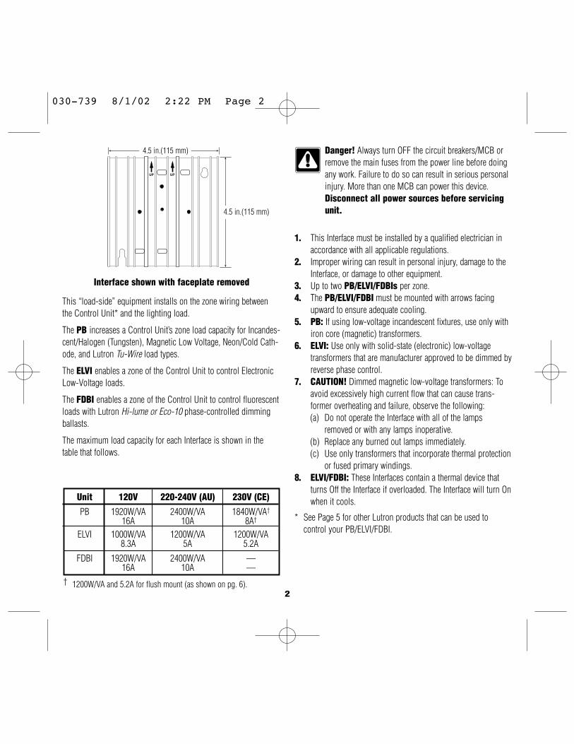
Unit
PB
ELVI
FDBI
120V
1920W/VA16A
1000W/VA8.3A
1920W/VA16A
220-240V (AU)
2400W/VA10A
1200W/VA5A
2400W/VA10A
230V (CE)
1840W/VA†
8A†
1200W/VA5.2A
——
Interface shown with faceplate removed
2
UP UP
4.5 in.(115 mm)
4.5 in.(115 mm)
Danger! Always turn OFF the circuit breakers/MCB orremove the main fuses from the power line before doingany work. Failure to do so can result in serious personalinjury. More than one MCB can power this device.Disconnect all power sources before servicingunit.
This “load-side” equipment installs on the zone wiring betweenthe Control Unit* and the lighting load.
The PB increases a Control Unit’s zone load capacity for Incandes-cent/Halogen (Tungsten), Magnetic Low Voltage, Neon/Cold Cath-ode, and Lutron Tu-Wire load types.
The ELVI enables a zone of the Control Unit to control ElectronicLow-Voltage loads.
The FDBI enables a zone of the Control Unit to control fluorescentloads with Lutron Hi-lume or Eco-10 phase-controlled dimmingballasts.
The maximum load capacity for each Interface is shown in thetable that follows.
1. This Interface must be installed by a qualified electrician inaccordance with all applicable regulations.
2. Improper wiring can result in personal injury, damage to theInterface, or damage to other equipment.
3. Up to two PB/ELVI/FDBIs per zone.4. The PB/ELVI/FDBI must be mounted with arrows facing
upward to ensure adequate cooling.5. PB: If using low-voltage incandescent fixtures, use only with
iron core (magnetic) transformers.6. ELVI: Use only with solid-state (electronic) low-voltage
transformers that are manufacturer approved to be dimmed byreverse phase control.
7. CAUTION! Dimmed magnetic low-voltage transformers: Toavoid excessively high current flow that can cause trans-former overheating and failure, observe the following:(a) Do not operate the Interface with all of the lamps
removed or with any lamps inoperative.(b) Replace any burned out lamps immediately.(c) Use only transformers that incorporate thermal protection
or fused primary windings.8. ELVI/FDBI: These Interfaces contain a thermal device that
turns Off the Interface if overloaded. The Interface will turn Onwhen it cools.
* See Page 5 for other Lutron products that can be used tocontrol your PB/ELVI/FDBI.
† 1200W/VA and 5.2A for flush mount (as shown on pg. 6).
030-739 8/1/02 2:22 PM Page 2

HOT/LIVE
ZONE
NEUTRAL 4321
US
A: C
lass
2IE
C: P
ELV
DO N
OT U
SE H/LN
HOT/
LIVE
EART
H/GR
OUND
ZONE
OUT
ZONE
INNE
UTRA
L N
■ Turn power Off.■ PB/ELVI: Connect standard switch between Hot/Live lead and
the load wire to test circuit.■ FDBI: Connect standard switch between Hot/Live lead and the
Dimmed Hot/Live and switched Hot/Live leads of the ballast.■ Turn power On and check for short or open circuits.
3
Test load for short circuits
Wiring Instructions1. Turn power Off to the Control Unit and the feed to the PB,
ELVI, or FDBI!2. Mount standard U.S. 2-gang wallbox* (available from Lutron,
P/N 241-641), 3 1/2 in. (87 mm) deep is strongly recom-mended, 2 3/4 in. (68 mm) minimum. Allow at least 4 1/2 in.(110 mm) clearance above/below Interfaces to ensure properheat dissipation.
3. Strip 1/2 in. (12 mm) insulation from all wires in wallbox andwire as shown. All connections are made using #12 AWG(2.5 mm2) wire. Power terminals can accept up to two#12 AWG (2.5 mm2) wires. The NEUTRAL N terminal is forthe Control neutral, not the load neutral! The recommendedinstallation torque is 9.0 in.●lbs. (1.0 N●m) for line voltageconnections.
Single-Feed Wiring for PB/ELVI120V and 220-240V
The PB/ELVI may be on the same circuit as the ControlUnit only if the total load does not exceed the rating ofthe breaker.
Dual-Feed Wiring for PB/ELVI120V and 220-240V
The load breaker/MCB can be on a different phase than the controlbreaker/MCB.
* Wallbox may be flush mounted or surface mounted. If mount-ing Interface in a panel, please refer to Panel Mounting sectionfor important information.
PB/ELVI FDBI
HOT/LIVE
SWITCH
LOAD
HOT/LIVE SWITCHORANGE
BLACK/BROWNBALLAST LOAD NEUTRAL
1/2 in. (12 mm)
HOT/LIVE
ZONE
NEUTRAL 4321
US
A: C
lass
2IE
C: P
ELV
DO N
OT U
SE H/LN
HOT/
LIVE
EART
H/GR
OUND
ZONE
INNE
UTRA
L N
H/LN
ZONE
OUT
LOAD NEUTRAL
LOAD
LOAD
030-739 8/1/02 2:22 PM Page 3

Single-Feed Wiring for PB/ELVI230V
The PB/ELVI may be on the same circuit as the ControlUnit only if the total load does not exceed the rating ofthe breaker.
HOT/LIVE
ZONE
NEUTRAL 4321
US
A: C
lass
2IE
C: P
ELV
DO N
OT U
SE H/LN
HOT/
LIVE
EART
H/GR
OUND
ZONE
OUT
ZONE
INNE
UTRA
L N
H/LN
HOT/LIVE
ZONE
NEUTRAL 4321
US
A: C
lass
2IE
C: P
ELV
DO N
OT U
SE H/LN
HOT/
LIVE
EART
H/GR
OUND
ZONE
OUT
ZONE
INNE
UTRA
L N
Dual-Feed Wiring for PB/ELVI230V
The load breaker/MCB can be on a different phase than the controlbreaker/MCB.
LOAD NEUTRAL
LOAD NEUTRAL
4
■ When using a PB to control a Lutron Tu-Wire dimming bal-last, the associated zone on the GRAFIK Eye® 3000 SeriesControl Unit must be set to the Tu-Wire load type. Pleasesee the GRAFIK Eye 3000 Series Installer’s Guide for moredetails.
■ The PB 230V must not be used with Tu-Wire ballastsbecause the Tu-Wire load type is not available on 230V CEmodels of the GRAFIK Eye Control Unit.
LOAD
LOAD
Tu-Wire Dimming Ballast
HOT/LIVE
ZONE
NEUTRAL 4321
US
A: C
lass
2IE
C: P
ELV
DO N
OT U
SE H/LN
HOT/
LIVE
EART
H/GR
OUND
ZONE
INNE
UTRA
L N
H/LN
ZONE
OUT
DO N
OT U
SE
HOT/
LIVE
EART
H/GR
OUND
ZONE
INNE
UTRA
L N
ZONE
OUT
H/LN
Dual-Feed Wiring for Two (2) PB/ELVI Interfaces on OneZone - 120V and 220-240VThe load breaker/MCB can be on a different phase than the controlbreaker/MCB.
LOAD NEUTRALLOAD
LOAD NEUTRALLOAD
030-739 8/1/02 2:22 PM Page 4
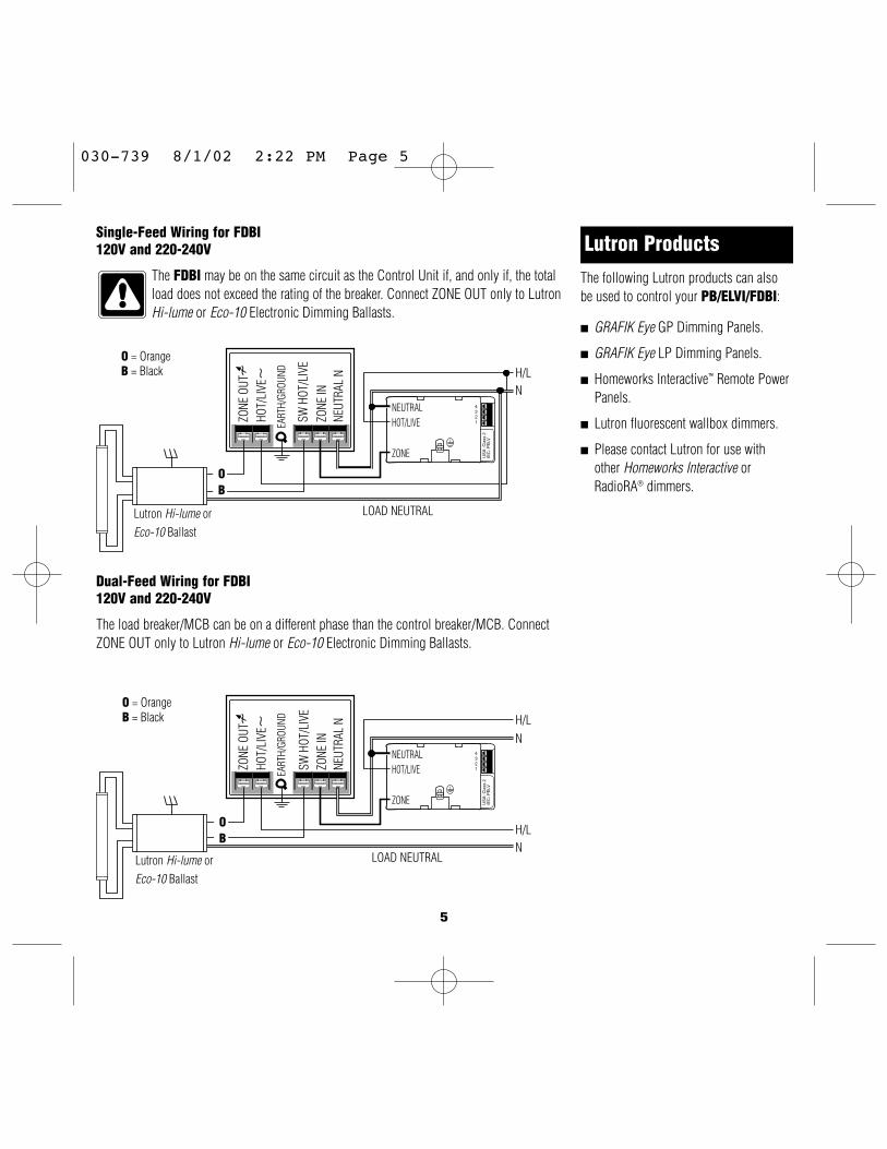
HOT/LIVE
ZONE
NEUTRAL 4321
US
A: C
lass
2IE
C: P
ELV
SW H
OT/L
IVE
H/LN
HOT/
LIVE
EART
H/GR
OUND
ZONE
OUT
ZONE
INNE
UTRA
L N
HOT/LIVE
ZONE
NEUTRAL 4321
US
A: C
lass
2IE
C: P
ELV
SW H
OT/L
IVE
H/LN
HOT/
LIVE
EART
H/GR
OUND
ZONE
OUT
ZONE
INNE
UTRA
L N
H/LN
5
Single-Feed Wiring for FDBI120V and 220-240V
The FDBI may be on the same circuit as the Control Unit if, and only if, the totalload does not exceed the rating of the breaker. Connect ZONE OUT only to LutronHi-lume or Eco-10 Electronic Dimming Ballasts.
Dual-Feed Wiring for FDBI120V and 220-240V
The load breaker/MCB can be on a different phase than the control breaker/MCB. ConnectZONE OUT only to Lutron Hi-lume or Eco-10 Electronic Dimming Ballasts.
Lutron ProductsThe following Lutron products can alsobe used to control your PB/ELVI/FDBI:
■ GRAFIK Eye GP Dimming Panels.
■ GRAFIK Eye LP Dimming Panels.
■ Homeworks Interactive™ Remote PowerPanels.
■ Lutron fluorescent wallbox dimmers.
■ Please contact Lutron for use withother Homeworks Interactive orRadioRA® dimmers.
LOAD NEUTRAL
LOAD NEUTRALLutron Hi-lume orEco-10 Ballast
Lutron Hi-lume orEco-10 Ballast
OB
O = OrangeB = Black
OB
O = OrangeB = Black
030-739 8/1/02 2:22 PM Page 5
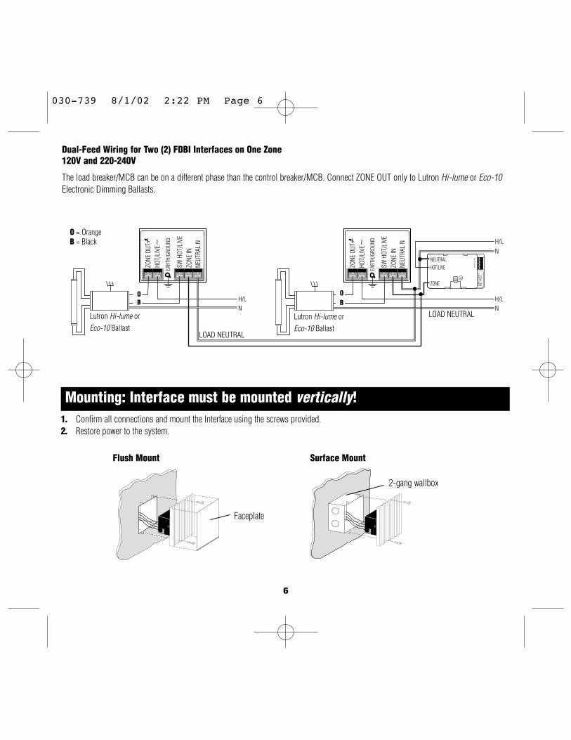
6
1. Confirm all connections and mount the Interface using the screws provided.2. Restore power to the system.
Mounting: Interface must be mounted vertically!
2-gang wallbox
Faceplate
Flush Mount Surface Mount
SW H
OT/L
IVE
HOT/
LIVE
EART
H/GR
OUND
ZONE
OUT
ZONE
INNE
UTRA
L N
H/LN
HOT/LIVE
ZONE
NEUTRAL 4321
US
A: C
lass
2IE
C: P
ELV
SW H
OT/L
IVE
H/LN
HOT/
LIVE
EART
H/GR
OUND
ZONE
OUT
ZONE
INNE
UTRA
L N
H/LN
Dual-Feed Wiring for Two (2) FDBI Interfaces on One Zone120V and 220-240V
The load breaker/MCB can be on a different phase than the control breaker/MCB. Connect ZONE OUT only to Lutron Hi-lume or Eco-10Electronic Dimming Ballasts.
LOAD NEUTRAL
LOAD NEUTRALLutron Hi-lume orEco-10 Ballast
Lutron Hi-lume orEco-10 Ballast
OB
OB
O = OrangeB = Black
030-739 8/1/02 2:22 PM Page 6

Symptom
Lights do not come on.
Lights turn on/offunexpectedly.
Troubleshooting Guide
PB
ELVI
FDBI
4 1/2 in. (11 cm) MINIMUM
4 1/2 in. (11 cm) MINIMUM
Panel Mounting■ The enclosure must be in accordance with all local and national electrical
codes.■ Lutron does not recommend using a door to enclose the front of a panel, since
this restricts airflow to the GRAFIK Eye Control Units and Interfaces. ■ If mounting multiple Control Units or Interfaces in an enclosure:
1. Ambient temperature within an enclosure must remain between32°—104° F (0°—40° C).
2. If not mounting in a metal enclosure, all units must be mounted in awallbox.
■ To improve heat dissipation of Power Interfaces, remove the faceplate from theunit.
GRAFIK Eye Control Units and Interface Units dissipate heat whenoperating. Obstructing these units can cause malfunction to both theControl Unit and the Interface if ambient temperature does not remainbetween 32°—104° F (0°—40° C).
Causes
Power is off
MiswireBulb(s)/lamp(s) burned outGRAFIK Eye 3000 ControlUnit
Interface is overloaded
Load Type
GRAFIK Eye 3000 ControlUnit
Solution
Restore power to the PB/ELVI/FDBI.Restore power to the Control Unit.Confirm wiring per wiring diagrams.Replace bulb(s)/lamp(s).Refer to troubleshooting section of GRAFIK Eye Control Unit Installer’sGuide.Check for excess load, proper mounting, and adequate air convection.Allow unit to cool.
Confirm that the load type being switched/dimmed is compatible withthe PB/ELVI/FDBI.Refer to the troubleshooting section of GRAFIK Eye Control UnitInstallation Guide.
7
030-739 8/1/02 2:22 PM Page 7

Lutron Electronics Co., Inc.Made and printed in U.S.A.P/N 030-739 Rev. A 2/02
Internet: www.lutron.comE-mail: [email protected]
WORLD HEADQUARTERSLutron Electronics Co. Inc.,TOLL FREE: (800) 523-9466(U.S.A., Canada, Caribbean)Tel: (610) 282-3800;International 1- 610-282-3800Fax: (610) 282-3090;International 1-610-282-3090
ASIAN HEADQUARTERSLutron Asuka Co, Ltd.,TOLL FREE: (0120) 083417 (Japan)Tel: (03) 5405-7333;International 81-3-5405-7333Fax: (03) 5405-7496;International 81-3-5405-7496
EUROPEAN HEADQUARTERSLutron EA Ltd.,FREEPHONE: 0800 282107 (U.K.)Tel: (207) 702-0657;International 44-207-702-0657Fax: (207) 480-6899;International 44-207-480-6899
HONG KONG SALES OFFICELutron GL (Hong Kong)Tel: 2104-7733;International 852-2104-7733Fax: 2104-7633;International 852-2104-7633
SINGAPORELutron GL (Singapore)Tel: 65 220 4666Fax: 65 220 4333
LIMITED WARRANTYLutron will, at its option, repair or replace any unit that is defec-tive in materials or manufacture within one year after purchase.For warranty service, return unit to place of purchase or mail toLutron at 7200 Suter Rd., Coopersburg, PA 18036-1299, postagepre-paid.This warranty is in lieu of all other express warranties,and the implied warranty of merchantability is limitedto one year from purchase. This warranty does notcover the cost of installation, removal, or reinstalla-tion, or damage resulting from misuse, abuse, orimproper or incorrect repair, or damage from improperwiring or installation. This warranty does not coverincidental or consequential damages. Lutron’s liabilityon any claim for damages arising out of or in connec-tion with the manufacture, sale, installation, delivery,or use of the unit shall never exceed the purchaseprice of the unit.This warranty gives you specific legal rights, and you may alsohave other rights which vary from state to state. Some states donot allow limitations on how long an implied warranty lasts, sothe above limitation may not apply to you. Some states do notallow the exclusion or limitation of incidental or consequentialdamages, so the above limitation or exclusion may not apply toyou.This product may be covered by one or more of the followingU.S. patents: 4,797,599; 4,803,380; and corresponding foreignpatents.Lutron, GRAFIK Eye, Hi-lume, Homeworks, Radio RA, and Tu-Wire are registered trademarks, and Eco-10, Tu-Wire, andHomeworks Interactive are trademarks of Lutron Electronics Co.,Inc.© 2002 Lutron Electronics Co., Inc.
030-739 8/1/02 2:22 PM Page 8

Power ModulesInstallation InstructionsPlease Read
R
®
SwitchingPower Module
Phase-Adaptive Power Module
3-Wire FluorescentPower Module
Models and CapacitiesModule Type Control Load Load Capacity Model NumberPhase-Adaptive 120 V 120 - 277 V 16 A PHPM-PA-DV-WH
50 / 60 Hz 50 / 60 HzPhase-Adaptive 120 V 120 V 16 A PHPM-PA-120-WH
50 / 60 Hz 50 / 60 Hz3-Wire Fluorescent 120 V 120 - 277 V 16 A PHPM-3F-DV-WH
50 / 60 Hz 50 / 60 Hz3-Wire Fluorescent 120 V 120 V 16 A PHPM-3F-120-WH
50 / 60 Hz 50 / 60 HzSwitching 120 V 120 - 277 V 16 A PHPM-SW-DV-WH
50 / 60 Hz 50 / 60 Hz
Eng
lishE
spaño
lFrançais
General NotesDanger! Always turn OFF the circuitbreakers or remove the main fuses fromthe power line before doing any work.Failure to do so can result in seriouspersonal injury. More than one disconnectmay be required to de-energize thisdevice. Disconnect all power sourcesbefore servicing unit.
• This power module must be installed by aqualified electrician in accordance with allapplicable regulations.
• Improper wiring can result in personal injury,damage to the interface, or damage to otherequipment.
• Up to three power modules per zone.• The power module must be mounted with arrow
facing upward to ensure adequate cooling.• CAUTION! Dimmed magnetic low-voltage
transformers: To avoid excessively high currentflow that can cause transformer overheating andfailure, observe the following:(a) Do not operate the power module with all of
the lamps removed or with any lampsinoperative.
(b) Replace any burned out lamps immediately.(c) Use only transformers that incorporate
thermal protection or fused primary windings.
2 GRAFIK Eye® Power Modules R
• Phase-Adaptive/Fluorescent: These powermodules contain circuitry that will shut down theoutput if it is overloaded. To correct the problem,turn off power and reduce the load to thespecified rating before re-applying power.
Note! Plastic faceplate must be installed onmodule for normal operation (all models).

GRAFIK Eye® Power Modules 3R
Load Type CapabilitySwitching Power Module:
• Incandescent (tungsten)• Halogen• Magnetic low-voltage transformer (iron core)• Electronic (solid-state) low-voltage transformer.• Magnetic and electronic fluorescent lamp
ballasts• Neon/cold-cathode• HID• Motor
- 1/2 HP at 277 V- 1/3 HP at 120 V
Phase-Adaptive Power Module:• Incandescent (tungsten)• Halogen• Magnetic low-voltage transformer (iron core)• Electronic (solid-state) low-voltage transformer• Lutron Tu-WireTM electronic fluorescent dimming
ballast• Neon/cold-cathode
3-Wire Fluorescent Power Module:• Lutron Hi-Lume and Eco-10 (Eco Series) line-
voltage control electronic dimming ballasts
Product CompatibilityThe following Lutron products may be used tocontrol these power modules:
• GRAFIK Eye QS control units• GRAFIK Eye 3000 Series control units• LP, LCP, GP dimming panels• HomeWorks remote power panels
Test Load for Short-Circuit• Turn power Off.• Phase-Adaptive/Switching: Connect standard
switch between Hot/Live lead and the load wireto test circuit.
• Fluorescent: Connect standard switch betweenHot/Live lead and the Dimmed Hot/Live andswitched Hot/Live leads of the ballast.
• Turn power On and check for short or opencircuits.
Phase-Adaptive/Switching
Fluorescent
Hot/Live
Neutral
Neutral
Hot/Live
Switch
Switch
Orange
Black/BrownBallast
Load
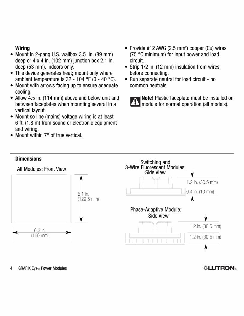
4 GRAFIK Eye® Power Modules R
Wiring• Mount in 2-gang U.S. wallbox 3.5 in. (89 mm)
deep or 4 x 4 in. (102 mm) junction box 2.1 in.deep (53 mm). Indoors only.
• This device generates heat; mount only whereambient temperature is 32 - 104 °F (0 - 40 °C).
• Mount with arrows facing up to ensure adequatecooling.
• Allow 4.5 in. (114 mm) above and below unit andbetween faceplates when mounting several in avertical layout.
• Mount so line (mains) voltage wiring is at least 6 ft. (1.8 m) from sound or electronic equipmentand wiring.
• Mount within 7° of true vertical.
6.3 in.(160 mm) 1.2 in. (30.5 mm)
1.2 in. (30.5 mm)
0.4 in. (10 mm)
1.2 in. (30.5 mm)
5.1 in.(129.5 mm)
DimensionsSwitching and
3-Wire Fluorescent Modules:Side View
Phase-Adaptive Module:Side View
All Modules: Front View
• Provide #12 AWG (2.5 mm2) copper (Cu) wires (75 °C minimum) for input power and loadcircuit.
• Strip 1/2 in. (12 mm) insulation from wiresbefore connecting.
• Run separate neutral for load circuit - nocommon neutrals.
Note! Plastic faceplate must be installed onmodule for normal operation (all models).

GRAFIK Eye® Power Modules 5R
Mounting Inside an Enclosure with GRAFIK Eye Control Units
• Mount in accordance with all local and nationalelectrical codes.
• Proper ventilation is required. Ambienttemperature inside enclosure must remainbetween 32 - 104 °F (0 - 40 °C) when GRAFIKEye control units and power modules areoperating.
• See diagram below for required spacing betweenunits.
Note! Plastic faceplate must be installed onmodule for normal operation (all models).
Mounting MethodsMount to 2-gang U.S. wallbox
Mount to 4 x 4 in. (102 mm), 2.1 in. (53 mm)deep U.S. junction box
Mount to 4 x 4 in. (102 mm), 2.1 in. (53 mm)deep U.S. junction box with barrier (for 277 Vloads if required by local electrical code) LUTRON LUTRON
LUTRON LUTRON
LUTRON LUTRON
4.5 in. (110 mm)minimum
4.5 in. (110 mm)minimum
PowerModule
GRAFIK Eye
Barrier

Single-Feed WiringThe power module may be on the same circuit as the control unit only if the total load does not exceedthe rating of the branch circuit breaker in accordance with local and national electrical codes.
6 GRAFIK Eye® Power Modules R
1 2 3 4 5 6 L N
H/LN
DH
H/LN
Load
GRAFIK Eye QS
Phase-Adaptive Module Wiring
Zone inControl Neutral
Wire to appropriate zone
LegendH/L Hot/LiveN NeutralSH Switched HotDH Dimmed Hot
GroundNot Used
Circuit breaker

GRAFIK Eye® Power Modules 7R
1 2 3 4 5 6 L N
H/LNSH
1 2 3 4 5 6 L N
H/LNSHDH
H/LN
H/LN
Load
Ballast
Switching Module Wiring
GRAFIK Eye QS
GRAFIK Eye QS
Zone inControl Neutral
Wire to appropriate zone
Fluorescent 3-Wire Module Wiring
Zone inControl Neutral
Wire to appropriate zone
Circuitbreaker
Circuit breaker

8 GRAFIK Eye® Power Modules R
Dual-Feed WiringThe load breaker can be on a different phase than the control breaker. Both breakers must be turnedoff prior to installing or servicing the module.
1 2 3 4 5 6 L N
H/LN
DH
NH/L
Load
Zone inControl Neutral
GRAFIK Eye QS
Wire to appropriate zone
LegendH/L Hot/LiveN NeutralSH Switched HotDH Dimmed Hot
GroundNot Used
H/LN
Loadbreaker
Controlbreaker
Phase-Adaptive Module Wiring

GRAFIK Eye® Power Modules 9R
1 2 3 4 5 6 L N
H/LNSH
1 2 3 4 5 6 L N
H/LNSHDH
NH/L
NH/L
Load
Ballast
Zone inControl Neutral
Wire to appropriate zone
Zone inControl Neutral
GRAFIK Eye QS
GRAFIK Eye QS
Wire to appropriate zone
H/LN
H/LN
Loadbreaker
Controlbreaker
Loadbreaker
Controlbreaker
Switching Module Wiring
Fluorescent 3-Wire Module Wiring

10 GRAFIK Eye® Power Modules R
1Remove power; repair fault; re-apply power.2Verify proper load on output.3Replace power module; internal device isdamaged.
4Possible faulty MLV load.
Output Status LED (Red)
Module Status LED (Green)
PHASE-ADAPTIVE POWER MODULE DIAGNOSTICS AND TROUBLESHOOTING
Module Status LED (green)LED Action CommentsOff Module not powered.
Caution: Control input may still be powered. Turn off all breakersbefore removing unit.
1 blink/second (“heartbeat”) Module powered; normal operation
Output Status LED (red)LED Action Control Input Load
Status Status CommentsOff Input signal off Off Load off
or disconnectedContinuously on On On Incandescent/electronic dimming1 blink/second (“heartbeat”) On On Magnetic dimming1 blink, pause, repeat On Off Load short-circuit/overload1
2 blinks, pause, repeat On Off Over-voltage error2
3 blinks, pause, repeat On On full Shorted component3
4 blinks, pause, repeat On Off DC detection4

GRAFIK Eye® Power Modules 11R
Output Status LED (Red)
Module Status LED (Green)
3-WIRE FLUORESCENT POWER MODULEDIAGNOSTICS AND TROUBLESHOOTING
Module Status LED (green)LED Action CommentsOff Module not powered.
Caution: Control input may still be powered. Turn off all breakersbefore removing unit.
1 blink/second (“heartbeat”) Module powered; normal operation
Output Status LED (red)LED Action Control Input Load
Status Status CommentsOff Input signal off Off Load off
or disconnectedContinuously on On On Load on.
Note: Output may repeatedly turn on and off if DH is overloaded or ifDH and SH are miswired.
Output Status LED (Red)
Module Status LED (Green)
SWITCHING POWER MODULEDIAGNOSTICS AND TROUBLESHOOTING
Module Status LED (green)LED Action CommentsOff Module not powered.
Caution: Control input may still be powered. Turn off all breakersbefore removing unit.
1 blink/second (“heartbeat”) Module powered; normal operation
Output Status LED (red)Control Input Load
LED Action Status Status CommentsOff Input signal off Off Load off
or disconnectedContinuously on On On Load on

R
Lutron Electronics Co., Inc.One Year Limited Warranty
For a period of one year from the date of purchase, and subject to the exclusions and restrictions described below, Lutron warrantseach new unit to be free from manufacturing defects. Lutron will, at its option, either repair the defective unit or issue a credit equal to thepurchase price of the defective unit to the Customer against the purchase price of comparable replacement part purchased from Lutron.Replacements for the unit provided by Lutron or, at its sole discretion, an approved vendor may be new, used, repaired, reconditioned,and/or made by a different manufacturer.
If the unit is commissioned by Lutron or a Lutron approved third party as part of a Lutron commissioned lighting control system, theterm of this warranty will be extended, and any credits against the cost of replacement parts will be prorated, in accordance with thewarranty issued with the commissioned system, except that the term of the unit's warranty term will be measured from the date of itscommissioning.EXCLUSIONS AND RESTRICTIONSThis Warranty does not cover, and Lutron and its suppliers are not responsible for:1. Damage, malfunction or inoperability diagnosed by Lutron or a Lutron approved third party as caused by normal wear and tear, abuse,
misuse, incorrect installation, neglect, accident, interference or environmental factors, such as (a) use of incorrect line voltages, fuses orcircuit breakers; (b) failure to install, maintain and operate the unit pursuant to the operating instructions provided by Lutron and theapplicable provisions of the National Electrical Code and of the Safety Standards of Underwriter's Laboratories; (c) use of incompatibledevices or accessories; (d) improper or insufficient ventilation; (e) unauthorized repairs or adjustments; (f) vandalism; or (g) an act ofGod, such as fire, lightning, flooding, tornado, earthquake, hurricane or other problems beyond Lutron's control.
2. On-site labor costs to diagnose issues with, and to remove, repair, replace, adjust, reinstall and/or reprogram the unit or any of itscomponents.
3. Equipment and parts external to the unit, including those sold or supplied by Lutron (which may be covered by a separate warranty).4. The cost of repairing or replacing other property that is damaged when the unit does not work properly, even if the damage was caused
by the unit.EXCEPT AS EXPRESSLY PROVIDED IN THIS WARRANTY, THERE ARE NO EXPRESS OR IMPLIED WARRANTIES OF ANY TYPE,
INCLUDING ANY IMPLIED WARRANTIES OF FITNESS FOR A PARTICULAR PURPOSE OR MERCHANTABILITY. LUTRON DOES NOTWARRANT THAT THE UNIT WILL OPERATE WITHOUT INTERRUPTION OR BE ERROR FREE.
NO LUTRON AGENT, EMPLOYEE OR REPRESENTATIVE HAS ANY AUTHORITY TO BIND LUTRON TO ANY AFFIRMATION,REPRESENTATION OR WARRANTY CONCERNING THE UNIT. UNLESS AN AFFIRMATION, REPRESENTATION OR WARRANTY MADE BY ANAGENT, EMPLOYEE OR REPRESENTATIVE IS SPECIFICALLY INCLUDED HEREIN, OR IN STANDARD PRINTED MATERIALS PROVIDED BYLUTRON, IT DOES NOT FORM A PART OF THE BASIS OF ANY BARGAIN BETWEEN LUTRON AND CUSTOMER AND WILL NOT IN ANYWAY BE ENFORCEABLE BY CUSTOMER.
IN NO EVENT WILL LUTRON OR ANY OTHER PARTY BE LIABLE FOR EXEMPLARY, CONSEQUENTIAL, INCIDENTAL OR SPECIALDAMAGES (INCLUDING, BUT NOT LIMITED TO, DAMAGES FOR LOSS OF PROFITS, CONFIDENTIAL OR OTHER INFORMATION, ORPRIVACY; BUSINESS INTERRUPTION; PERSONAL INJURY; FAILURE TO MEET ANY DUTY, INCLUDING OF GOOD FAITH OR OFREASONABLE CARE; NEGLIGENCE, OR ANY OTHER PECUNIARY OR OTHER LOSS WHATSOEVER), NOR FOR ANY REPAIR WORKUNDERTAKEN WITHOUT LUTRON'S WRITTEN CONSENT ARISING OUT OF OR IN ANY WAY RELATED TO THE INSTALLATION,DEINSTALLATION, USE OF OR INABILITY TO USE THE UNIT OR OTHERWISE UNDER OR IN CONNECTION WITH ANY PROVISION OF THISWARRANTY, OR ANY AGREEMENT INCORPORATING THIS WARRANTY, EVEN IN THE EVENT OF THE FAULT, TORT (INCLUDINGNEGLIGENCE), STRICT LIABILITY, BREACH OF CONTRACT OR BREACH OF WARRANTY OF LUTRON OR ANY SUPPLIER, AND EVEN IFLUTRON OR ANY OTHER PARTY WAS ADVISED OF THE POSSIBILITY OF SUCH DAMAGES.
NOTWITHSTANDING ANY DAMAGES THAT CUSTOMER MIGHT INCUR FOR ANY REASON WHATSOEVER (INCLUDING, WITHOUTLIMITATION, ALL DIRECT DAMAGES AND ALL DAMAGES LISTED ABOVE), THE ENTIRE LIABILITY OF LUTRON AND OF ALL OTHERPARTIES UNDER THIS WARRANTY ON ANY CLAIM FOR DAMAGES ARISING OUT OF OR IN CONNECTION WITH THE MANUFACTURE,SALE, INSTALLATION, DELIVERY, USE, REPAIR, OR REPLACEMENT OF THE UNIT, OR ANY AGREEMENT INCORPORATING THISWARRANTY, AND CUSTOMER'S SOLE REMEDY FOR THE FOREGOING, WILL BE LIMITED TO THE AMOUNT PAID TO LUTRON BYCUSTOMER FOR THE UNIT. THE FOREGOING LIMITATIONS, EXCLUSIONS AND DISCLAIMERS WILL APPLY TO THE MAXIMUM EXTENTALLOWED BY APPLICABLE LAW, EVEN IF ANY REMEDY FAILS ITS ESSENTIAL PURPOSE.TO MAKE A WARRANTY CLAIM
To make a warranty claim, promptly notify Lutron within the warranty period described above by calling the Lutron Technical SupportCenter at (800) 523-9466. Lutron, in its sole discretion, will determine what action, if any, is required under this warranty. To better enableLutron to address a warranty claim, have the unit's serial and model numbers available when making the call. If Lutron, in its sole discretion,determines that an on-site visit or other remedial action is necessary, Lutron may send a Lutron Services Co. representative or coordinatethe dispatch of a representative from a Lutron approved vendor to Customer's site, and/or coordinate a warranty service call betweenCustomer and a Lutron approved vendor.
This warranty gives you specific legal rights, and you may also have other rights which vary from state to state. Some states do notallow limitations on how long an implied warranty lasts, so the above limitation may not apply to you. Some states do not allow the exclusionor limitation of incidental or consequential damages, so the above limitation or exclusion may not apply to you.
These products may be covered under one or more of the following U.S. patents: 4,797,599; 5,309,068; 5,633,540; 6,091,205;6,380,692; and corresponding foreign patents. U.S. and foreign patents pending.
Lutron, the sunburst logo, and GRAFIK Eye are registered trademarks and Tu-Wire is a trademark of Lutron Electronics Co., Inc.© 2007 Lutron Electronics Co., Inc.
Lutron Electronics Co., Inc.Made and printed in U.S.A.P/N 032-178 Rev. A 4/07
Internet: www.lutron.comE-mail: [email protected]
WORLD HEADQUARTERSLutron Electronics Co., Inc.7200 Suter Road, Coopersburg, PA18036-1299 USATEL +1.610.282.3800FAX +1.610.282.1243Technical Support 1.800.523.9466Toll-Free 1.888.LUTRON1
EUROPEAN HEADQUARTERSUnited KingdomLutron EA Ltd.6 Sovereign Close, London, E1W 3JF UKTEL +44.(0)20.7702.0657FAX +44.(0)20.7480.6899Technical support +44.(0)20.7680.4481FREEPHONE 0800.282.107
ASIAN HEADQUARTERSSingaporeLutron GL Ltd. 15 Hoe Chiang Road, #07-03 Euro Asia Centre, Singapore 089316TEL +65.6220.4666FAX +65.6220.4333
Asia Technical HotlinesNorthern China: 10.800.712.1536Southern China: 10.800.120.1536Hong Kong: 800.901.849Indonesia : 001.803.011.3994Japan: +81.3.5575.8411Macau : 0800.401Singapore: 800.120.4491Taiwan: 00.801.137.737Thailand: 001.800.120.665853Other Areas: +65.6220.4666

QS® Smart Power Supply Panel
Installation Instructions
QSPS-P1-10-60

Page �
Sivoia® QS QSPS-P�-�0-60 Installation instructions
QSPS-P1-10-60 120 V~ 60 Hz5 A Max Input Current
Installation Instructions (Please leave for occupant)
Please read before installing.
Tools Required:Wire Cutter/Stripper Power DrillSmall Flat-Head Screwdriver #2 Phillips Screwdriver
NOTE: Mounting hardware is not included due to the wide variety of wall materials. Customer should determine the appropriate mounting hardware for their specific needs.
Box Contents:QSPS-P�-�0-60
Important Notes
Adherence to these specifications is necessary to ensure a safe and successful installation.
�. All wiring must be in accordance with national and local electrical codes.2. QSPS-P�-�0-60 must be installed by a qualified electrician.3. Ambient operating temperature: 32 - �04 °F (0 - 40 °C), 0 - 90% humidity,
non-condensing. 4. This product is intended for indoor use only.5. Separate over current protection is required to be provided in accordance with
Canadian Electrical Code, Part �.
1
�.�

Page 2
Sivoia® QS QSPS-P�-�0-60 Installation instructions
2
2.�
Installation
�. Mount QSPS-P1-10-60 using one of the following methods (Mounting Hardware is not provided) Do not mount in any other orientation.
a. Surface Mount - Use the keyholes located on the back of the enclosure to fasten the QSPS-P�-�0-60 to the wall. Use fasteners rated for a 50 lb. (23 kg) load. See illustration of QSPS-P�-�0-60 .
b. Recess Mount - Install a 2 in x 4 in (50 mm x �00 mm) board between the studs as a bottom support. Fasten the QSPS-P�-�0-60 to the right stud and bottom support inserting fasteners through the mounting holes provided.
CAUTION - The equipment is air-cooled. Mount in a location where the vented cover will not be blocked. A minimum of � ft. (300 mm) is necessary.
DANGER - Locate and lock the supply breaker in the OFF position before wiring to the terminal blocks.
�6 in. (406 mm)
�0.4 in. (264 mm)
4.8 in. (�2� mm)
�.2
in.
(30
mm
)�4
.8 in
. (3
75 m
m)
�7.5
in.
(445
mm
)
6 in. (�52 mm)
�.8 in. (45 mm)2 x 4 in. (50 x �00 mm) Bottom Support
2. Connect 120 V~ power wiring into the QSPS-P1-10-60. Remove one of the knockout tabs on the top left side of the enclosure near the input terminal blocks. In-sert a strain relief into the knockout hole. Run the power wire through the strain relief to the input terminal blocks at the top left side of the enclosure. Tighten terminal blocks to 3.5 to 5 in-lbs. (0.4-0.6 N•m).
Note: Maximum of � QSPS-P�-�0-60 per �5 A Breaker. Maximum of 2 QSPS-P�-�0-60 per 20 A Breaker. Maximum feed breaker size of 30 Amps. Use only High-Magnetic breakers.

Page 3
Sivoia® QS QSPS-P�-�0-60 Installation instructions
2
2.2 QSPS-P�-�0-60 Parts identification
Installation (continued)
Diagnostic Buttons All Lights OnAll Lights Off
All Shades OpenAll Shades Close
Power Supply Clear
Reserved for future use
Reserved for future use
Diagnostic LED – Communication Link Traffic
Status LED
FUSE 5X20FUSE 5X20 10 9 8 7 6 5 4 3 2 1 10 9 8 7 6 5 4 3 2 1
1 2 3 4 5 6 7 8 9 10
1
2
3
4
5
6
7
8
9
10
FU
SE
5X
20
CO
M
MU
X
MU
X
CO
M
MU
X
MU
X
LINK
FUSE 5X20FUSE 5X20 10 9 8 7 6 5 4 3 2 1 10 9 8 7 6 5 4 3 2 1
1 2 3 4 5 6 7 8 9 10
1
2
3
4
5
6
7
8
9
10
FU
SE
5X
20
CO
M
MU
X
MU
X
CO
M
MU
X
MU
X
LINK
FUSE 5X20FUSE 5X20 10 9 8 7 6 5 4 3 2 1 10 9 8 7 6 5 4 3 2 1
1 2 3 4 5 6 7 8 9 10
1
2
3
4
5
6
7
8
9
10
FU
SE
5X
20
CO
M
MU
X
MU
X
CO
M
MU
X
MU
X
LINK
FUSE 5X20FUSE 5X20 10 9 8 7 6 5 4 3 2 1 10 9 8 7 6 5 4 3 2 1
1 2 3 4 5 6 7 8 9 10
1
2
3
4
5
6
7
8
9
10
FU
SE
5X
20
CO
M
MU
X
MU
X
CO
M
MU
X
MU
X
LINK
FUSE 5X20FUSE 5X20 10 9 8 7 6 5 4 3 2 1 10 9 8 7 6 5 4 3 2 1
1 2 3 4 5 6 7 8 9 10
1
2
3
4
5
6
7
8
9
10
FU
SE
5X
20
CO
M
MU
X
MU
X
CO
M
MU
X
MU
X
LINK
�20 V~ input terminal blocks
Spare fuses 5x20 mm 2.5 A
4-pin connectorpower and communication to Lutron lighting and shading devices
LED – Output status (� per output, �0 outputs)
3-pin connector communication to additional power supplies
FUSE 5X20FUSE 5X20 10 9 8 7 6 5 4 3 2 1 10 9 8 7 6 5 4 3 2 1
1 2 3 4 5 6 7 8 9 10
1
2
3
4
5
6
7
8
9
10
FU
SE
5X
20
CO
M
MU
X
MU
X
CO
M
MU
X
MU
X
LINK

Page 4
Sivoia® QS QSPS-P�-�0-60 Installation instructions
QS Link Wiring3
3.� Link Rules
The following Link rules must be observed for proper operation. - Maximum of �00 devices (such as a GRAFIK Eye® QS, QS keypad,
QSPS-P�-�0-60, or Sivoia® QS shade) - Maximum of �00 zones (such as a Sivoia QS shade, or a lighting zone on a
GRAFIK Eye QS) - Maximum 2,000 ft (600 m) of cable connecting all QSPS-P�-�0-60 panels - Maximum 2,000 ft (600 m) of cable to devices wired to each QSPS-P�-�0-60 - Use only cable with at least one twisted/shielded pair for communications (MUX and MUX)
3.2 Wire Length Chart
Maximum devices per one output Maximum distance per one output based on wire guage
Shades + Controls#12 AWG(4 mm2)
#16 AWG(1.5 mm2)
#18 AWG (1 mm2)
GRX-CBL-346S-500
NoneUp to 6
seeTouch QS keypads
1000 ft. (300 m)
500 ft. (150 m)
250 ft. (75 m)
1 Sivoia QS roller 64TM
None500 ft. (150 m)
200 ft. (60 m)
100 ft. (30 m)
1 Sivoia QS roller 64
Up to 2seeTouch QS
keypads
250 ft. (75 m)
75 ft. (20 m)
50 ft. (15 m)
2 Sivoia QS roller 64, ≤ 30 sq ft
(2.75 sq m) eachNone
250 ft. (75 m)
75 ft. (20 m)
50 ft. (15 m)
3 Sivoia QS roller64, ≤ 20 sq ft
(1.8 sq m) eachNone
250 ft. (75 m)
75 ft. (20 m)
50 ft. (15 m)
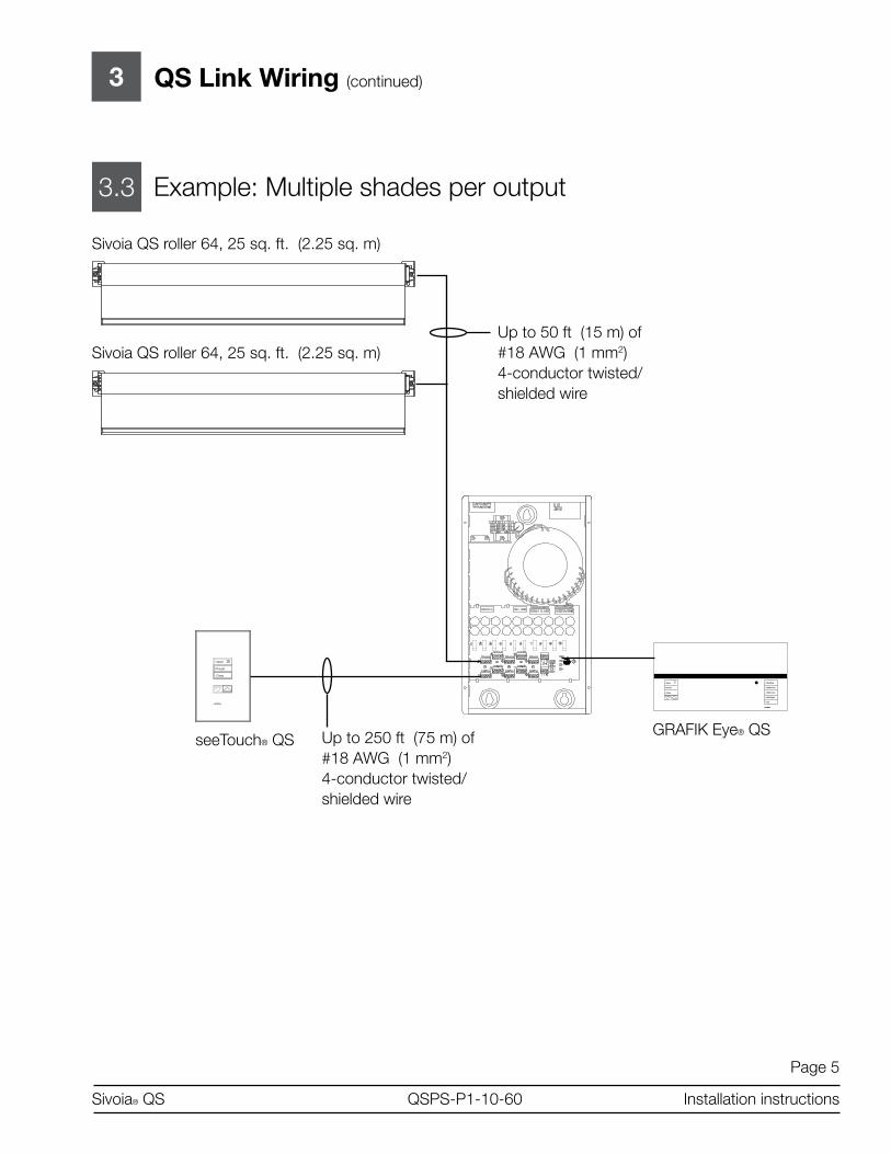
Page 5
Sivoia® QS QSPS-P�-�0-60 Installation instructions
3 QS Link Wiring (continued)
3.3 Example: Multiple shades per output
Sivoia QS roller 64, 25 sq. ft. (2.25 sq. m)
Sivoia QS roller 64, 25 sq. ft. (2.25 sq. m)Up to 50 ft (�5 m) of #�8 AWG (� mm2) 4-conductor twisted/shielded wire
Close
Preset
Open Meeting
Videoconf
Afternoon
A/V Night
OffLUTRON
Close
Open
Preset
seeTouch® QSGRAFIK Eye® QSUp to 250 ft (75 m) of
#�8 AWG (� mm2)4-conductor twisted/shielded wire

Page 6
Sivoia® QS QSPS-P�-�0-60 Installation instructions
QS Link Wiring (continued)3
3.4 Example: One shade per output
Up to 250 ft (75 m) of #�8 AWG (� mm2)4-conductor twisted/shielded wire
GRAFIK Eye® QS
Close
Preset
Open Meeting
Videoconf
Afternoon
A/V Night
Off
Sivoia QS roller 64, 25 sq. ft. (2.25 sq. m)
Sivoia QS roller 64, 25 sq. ft. (2.25 sq. m)
Up to �00 ft (30 m) of #�8 AWG (� mm2)4-conductor twisted/shielded wire
LUTRON
Close
Open
Preset
seeTouch® QS
Up to �00 ft (30 m) of #�8 AWG (� mm2)4-conductor twisted/shielded wire

1
�.�
Page 7
Sivoia® QS QSPS-P�-�0-60 Installation instructions
4
4.�
Wiring the QSPS-P1-10-60
Run low voltage wire into the QSPS-P�-60
Remove as many knockout tabs as necessary from the left side of the enclosure and insert strain reliefs.
Run the low-voltage communication wiring from the Lutron QS shade and lighting devices through the strain reliefs to the terminal blocks.
Strip insulation wire so that .25 in. (7 mm) of bare wire is exposed. Make sure to tighten the screws tightly and that no insulation is inside of the terminal block.
Input power from distribution panel
Hot (Live)NeutralEarth Ground
Low voltage wiring(To Lutron shade and lighting components)

1
�.�
Page 8
Sivoia® QS QSPS-P�-�0-60 Installation instructions
4
4.2
Wiring the QSPS-P1-10-60 (continued)
Connecting Multiple QSPS-P�-�0-60 Panels
Use the two 3-pin terminal blocks when connecting multiple QSPS-P�-�0-60 panels.
From additional QSPS-P�-�0-60 panels
To additional QSPS-P�-�0-60 panels
Device Link4 - conductor power and communications to devices. Max 2,000 ft. (600 m) per QSPS-P�-�0-60
Panel Link3 - conductor communications Max 2,000 ft. (600 m) connecting all QSPS-P�-�0-60 panels.

Page 9
Sivoia® QS QSPS-P�-�0-60 Installation instructions
5
5.�
DiagnosticsThe QSPS-P�-�0-60 provides built-in diagnostics to help troubleshoot and verify your installation.
Output status LEDsEach output has a status LED to indicate if the output is properly powered. If an output becomes overloaded, its status LED will blink to indicate the fault condition. Press the “Power Supply Clear” button after the fault condition has been cleared and the LED will stop blinking.
Output status LEDs
FUSE 5X20FUSE 5X20 10 9 8 7 6 5 4 3 2 1 10 9 8 7 6 5 4 3 2 1
1 2 3 4 5 6 7 8 9 10
1
2
3
4
5
6
7
8
9
10
FU
SE
5X
20
CO
M
MU
X
MU
X
CO
M
MU
X
MU
X
LINK
LED
FUSE 5X20FUSE 5X20 10 9 8 7 6 5 4 3 2 1 10 9 8 7 6 5 4 3 2 1
1 2 3 4 5 6 7 8 9 10
1
2
3
4
5
6
7
8
9
10
FU
SE
5X
20
CO
M
MU
X
MU
X
CO
M
MU
X
MU
X
LINK
If an output status LED has turned off, the fuse will need to be replaced. The QSPS-P�-�0-60 comes with two spare 5x20 mm 2.5A fuses.
Fuses
FUSE 5X20FUSE 5X20 10 9 8 7 6 5 4 3 2 1 10 9 8 7 6 5 4 3 2 11 2 3 4 5 6 7 8 9 10
1
2
3
4
5
6
7
8
9
10
FU
SE
5X
20
CO
M
MU
X
MU
X
CO
M
MU
X
MU
X
LINK
Spare fuses
FUSE 5X20FUSE 5X20 10 9 8 7 6 5 4 3 2 1 10 9 8 7 6 5 4 3 2 1
1 2 3 4 5 6 7 8 9 10
1
2
3
4
5
6
7
8
9
10
FU
SE
5X
20
CO
M
MU
X
MU
X
CO
M
MU
X
MU
X
LINK

Page �0
Sivoia® QS QSPS-P�-�0-60 Installation instructions
5
5.2
Diagnostics (continued)
Communications Link LEDsThe QSPS-P�-�0-60 has four diagnostic LEDs for the communications link.
Diagnostic LEDs
Reserved for future use
Reserved for future use
Link TrafficThis LED will blink green to indicate that devices are communicating.
Status LEDThis LED indicates that the panel is operating properly. If this LED is off, check your wiring.

Page ��
Sivoia® QS QSPS-P�-�0-60 Installation instructions
5
5.3
Diagnostics (continued)
Verify CommunicationsTo verify the communications of your system, tap, hold, tap, hold the All Shades Open button. The QSPS-P�-�0-60 is now trying to communicate with all other devices. All EDUs communicating on the link will wiggle and flash their green LED quickly. If you discover any EDUs that are not wiggling, verify that the EDU is powered and wired properly. Link Diagnostics Mode will automatically time out after �0 minutes.
To exit Link Diagnostics Mode, press and hold the All Shades Open button for 5 seconds.

Page �2
Sivoia® QS QSPS-P�-�0-60 Installation instructions
SCOPE This limited warranty (“Warranty”) covers the Lutron supplied (a) Sivoia® QS Shade System (“Sivoia® QS Shade System”), (b) Sivoia QEDTM Shade System (“Sivoia QEDTM Shade System”), (c) manual shade system and (d) alternating cur-rent or a/c shade system (each of the foregoing being a “System”). Customer acknowledges and agrees that use of the System constitutes accep-tance of all terms and conditions of this Warranty.
LIMITED WARRANTY Subject to the exclusions and restrictions de-scribed below, Lutron warrants that each System will be free from manufacturing defects from the date of shipment by Lutron for a period of (a) one year as to the wall controls, interfaces and system accessories of the Sivoia® QS Shade System (“External Sivoia® QS Components”) and (b) eight years as to the other Systems and the electronic drive unit, shade fabric and shade hardware of the Sivoia® QS Shade System. If any manufacturing defect exists in the External Sivoia® QS Components, so long as Customer promptly notifies Lutron of the defect within the one year warranty period and, if requested by Lutron, returns the defective part(s), Lutron will, at its option, either repair the defective part(s) or provide comparable replacement part(s). If any manufacturing defect exists in any of the components of a System other than the External Sivoia® QS Components, so long as Customer promptly notifies Lutron of the defect within the eight year warranty period and, if requested by Lutron, returns the defective part(s), Lutron will, at its option, either repair the defective part(s) or issue a credit to the Customer against the pur-chase price of comparable replacement part(s) purchased from Lutron as provided below:
Replacement parts for the System provided by Lutron or, at its sole discretion, an approved ven-dor may be new, used, repaired, reconditioned, and/or made by a different manufacturer.
EXCLUSIONS AND RESTRICTIONS This Warranty will be void, and Lutron and its suppliers will have no responsibility under this Warranty, if Lutron or its representatives can-not access any components of the System to inspect, diagnose problems with or repair the System or any of its components as a result of concealment or inaccessibility of such compo-nents within a building structure.
This Warranty does not cover, and Lutron and its suppliers are not responsible for:
�. Damage, malfunction or inoperability diag-nosed by Lutron or a Lutron approved third party as caused by normal wear and tear, abuse, misuse, incorrect installation, neglect, accident, interference or environmental fac-tors, such as (a) use of incorrect line voltages fuses or circuit breakers; (b) failure to install, maintain and operate the System pursuant to the operating instructions provided by Lutron and the applicable provisions of the National Electrical Code and of the Safety Standards of Underwriter’s Laboratories; (c) use of incom-patible devices or accessories; (d) improper or insufficient ventilation; (e) unauthorized repairs or adjustments or alterations; (f) vandalism; (g) an act of God, such as fire, lightning, flood-ing, tornado, earthquake, hurricane or other problems beyond Lutron’s control; or (h) direct exposure to corrosive materials.
2. On-site labor costs to diagnose issues with, and remove, repair, replace, adjust, reinstall and/or reprogram the System or any of its components.
3. Components and equipment external to the System, such as, non-Lutron lighting and automation systems; building wiring audio-vi-sual equipment; and non-Lutron time clocks, photosensors and motion detectors.
4. The cost of repairing or replacing other prop-erty that is damaged when any System does not work properly, even if the damage was caused by the System.
Limited Warranty
Number of years from date
of shipment
Percentage of cost of replacement parts credited by Lutron
Up to 2 �00%
More than 2 but not more than 5
50%
More than 5 but not more than 8
25%
More than 8 0%

Page �3
Sivoia® QS QSPS-P�-�0-60 Installation instructions
THIS WARRANTY IS IN LIEU OF ALL OTHER EXPRESS WARRANTIES. ALL IMPLIED WARRANTIES, INCLUDING THE IMPLIED WARRANTIES OF MERCHANTABILITY AND OF FITNESS FOR A PARTICULAR PUR-POSE, ARE LIMITED TO EIGHT YEARS FROM THE DATE OF SHIPMENT, EXCEPT THAT SUCH IMPLIED WARRANTIES ARE LIMITED TO ONE YEAR FROM THE DATE OF SHIPMENT AS TO THE EXTERNAL Sivoia QS COMPONENTS.
NO LUTRON AGENT, EMPLOYEE OR REP-RESENTATIVE HAS ANY AUTHORITY TO BIND LUTRON TO ANY AFFIRMATION, REP-RESENTATION OR WARRANTY CONCERN-ING THE SYSTEMS. UNLESS AN AFFIRMA-TION, REPRESENTATION OR WARRANTY MADE BY AN AGENT, EMPLOYEE OR REP-RESENTATIVE IS SPECIFICALLY INCLUDED HEREIN, OR IN STANDARD PRINTED MA-TERIALS PROVIDED BY LUTRON, IT DOES NOT FORM A PART OF THE BASIS OF ANY BARGAIN BETWEEN LUTRON AND CUS-TOMER AND WILL NOT IN ANY WAY BE ENFORCEABLE BY CUSTOMER.
IN NO EVENT WILL LUTRON OR ANY OTH-ER PARTY BE LIABLE FOR EXEMPLARY, CONSEQUENTIAL, INCIDENTAL OR SPE-CIAL DAMAGES (INCLUDING, BUT NOT LIMITED TO DAMAGES FOR PERSONAL INJURY, FAILURE TO MEET ANY DUTY, INCLUDING OF GOOD FAITH OR REASON-ABLE CARE, NEGLIGENCE, OR ANY OTHER LOSS WHATSOEVER), NOR FOR ANY RE-PAIR WORK UNDERTAKEN WITHOUT LU-TRON’S PRIOR WRITTEN CONSENT ARIS-ING OUT OF OR IN ANY WAY RELATED TO THE INSTALLATION, DEINSTALLATION, USE OF OR INABILITY TO USE THE SYSTEM OR OTHERWISE UNDER OR IN CONNEC-TION WITH ANY PROVISION OF THIS WAR-RANTY, EVEN IN THE EVENT OF THE FAULT, TORT (INCLUDING NEGLIGENCE), STRICT LIABILITY, BREACH OF CONTRACT OR BREACH OF WARRANTY OF LUTRON OR ANY OTHER PARTY, AND EVEN IF LUTRON OR SUCH OTHER PARTY WAS ADVISED OF THE POSSIBILITY OF SUCH DAMAGES.
NOTWITHSTANDING ANY DAMAGES THAT CUSTOMER MIGHT INCUR FOR ANY REA-SON WHATSOEVER (INCLUDING, WITHOUT LIMITATION, ALL DIRECT DAMAGES AND ALL DAMAGES LISTED ABOVE), THE EN-TIRE LIABILITY OF LUTRON AND OF ALL OTHER PARTIES UNDER THIS WARRANTY ON ANY CLAIM FOR DAMAGES ARISING OUT OF OR IN CONNECTION WITH THE MANUFACTURE, SALE, INSTALLATION, DE-LIVERY, USE, REPAIR, OR REPLACEMENT OF THE SYSTEM, AND CUSTOMER’S SOLE REMEDY FOR THE FOREGOING, WILL BE LIMITED TO THE AMOUNT PAID BY CUS-TOMER FOR THE SYSTEM. THE FOREGO-ING LIMITATIONS, EXCLUSIONS AND DIS-CLAIMERS WILL APPLY TO THE MAXIMUM EXTENT ALLOWED BY APPLICABLE LAW, EVEN IF ANY REMEDY FAILS ITS ESSEN-TIAL PURPOSE.
THIS WARRANTY GIVES YOU SPECIFIC LEGAL RIGHTS. YOU MAY ALSO HAVE OTHER RIGHTS WHICH VARY FROM STATE TO STATE. SOME STATES DO NOT ALLOW LIMITATIONS ON HOW LONG AN IMPLIED WARRANTY LASTS OR THE EXCLUSION OR LIMITATION OF INCIDENTAL OR CON-SEQUENTIAL DAMAGES, SO THE ABOVE LIMITATIONS OR EXCLUSIONS MAY NOT APPLY TO YOU.
WARRANTY CLAIMS, TECHNICAL ASSIS-TANCE AND WARRANTY INFORMATION.
Contact the Lutron Technical Support Center at the numbers provided below or your local Lutron sales representative with questions concerning the installation or operation of the System or this Warranty, or to make a warranty claim. Please provide the exact model number when calling.
U.S. and foreign patents pending.
Lutron, the Sunburst logo, and Sivoia QS are registered trademarks, and Sivoia QS and “Lighting Controls” are trademarks of Lutron Electronics Co., Inc.

Page �4
Sivoia® QS QSPS-P�-�0-60 Installation instructions
Technical AssistanceWORLD HEADQUARTERSLutron Electronics Co., Inc.7200 Suter RoadCoopersburg, PA �8036United StatesTel: +�-6�0-282-3800Fax:+�-6�0-282-�243
ASIAN HEADQUARTERSLutron GL Ltd.�5 Hoe Chiang Road#07-03 Tower FifteenSingapore 0893�6Tel: +65-6220-4666Fax: [email protected]
EUROPEAN HEADQUARTERSLutron EA Ltd.6 Sovereign CloseLondon, E�W 3JFUnited KingdomTel: +44-(0)20-7702-0657Fax: +44-(0)20-7480-6899
CUSTOMER SERVICE/ORDERINGUK +44-(0)20-7702-0657 – 09.00 - �8.00 GMTUSA +�-6�0-282-3800 – 08.00 - 20.00 EST
CUSTOMER SERVICE/[email protected]
TECHNICAL SUPPORT & SERVICESUSA +�-6�0-282-3800 – 24 hours/7 daysUK +44-(0)20-7702-065709.00 - �8.00 GMT
INTERNET: www.lutron.com
ADDITIONAL LUTRON SALES OFFICES:
Germany Tel: +49-309-7�0-4590 Fax: +49-309-7�0-459� FREEPHONE 00800-5887 6635
France Lutron Ltc, S.A.R.L.-Paris90 rue Villiers92300 Levallois Perret,FranceTel: +33-�-4�-05-42-80Fax: +33-�-4�-05-0�-80 FREEPHONE: 0800.90.�2.�[email protected]
Spain-Madrid Tel: +34-9�-567-84-79 Fax: +34-9�-567-84-78 FREEPHONE 0900-948-944
Spain-Barcelona Tel: +34-93-496-57-42 Fax: +34-93-496-57-50 FREEPHONE 0900-948-944
Hong Kong Tel: +852-2�04-7733 Fax: +852-2�04-7633
BeijingTel: +86-�0-5877-�8�7 Fax: +86-�0-5877-�8�6
SingaporeLUTRON GL Ltd. - Singapore�5 Hoe Chiang Road#7-03 Tower �5Singapore 0893�6Tel: +65-6220-4666Fax: +65-6220-4333
Japan Tel: +8�-3-5575-84�� Fax: +8�-3-5575-8420
www.lutron.com/shadingsolutions
USA and Canada (24 hrs/7days):call: 800-523-9466
Other countries (8 a.m. – 8 p.m. ET)call: +�-6�0-282-3800fax: +�-6�0-282-3090
email: [email protected]
©2007 LUTRON Electronics Co., Inc.Printed in the U.S.A.P/N 045-�27 REV. B

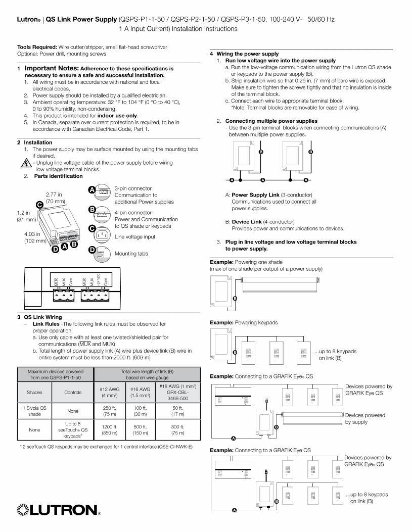
Lutron® | QS Link Power Supply (QSPS-P1-1-50 / QSPS-P2-1-50 / QSPS-P3-1-50, 100-240 V~ 50/60 Hz 1 A Input Current) Installation Instructions
Tools Required: Wire cutter/stripper, small flat-head screwdriverOptional: Power drill, mounting screws____________________________________________________________________
1 Important Notes: Adherence to these specifications is necessary to ensure a safe and successful installation.
1. All wiring must be in accordance with national and local electrical codes.
2. Power supply should be installed by a qualified electrician. 3. Ambient operating temperature: 32 °F to 104 °F (0 °C to 40 °C),
0 to 90% humidity, non-condensing. 4. This product is intended for indoor use only. 5. In Canada, separate over current protection is required, to be in
accordance with Canadian Electrical Code, Part 1.____________________________________________________________________2 Installation 1. The power supply may be surface mounted by using the mounting tabs
if desired. - Unplug line voltage cable of the power supply before wiring
low voltage terminal blocks. 2. Parts identification
____________________________________________________________________3 QS Link Wiring – Link Rules -The following link rules must be observed for
proper operation. a. Use only cable with at least one twisted/shielded pair for
communications (MUX and MUX) b. Total length of power supply link (A) wire plus device link (B) wire in
entire system must be less than 2000 ft. (609 m)
____________________________________________________________________4 Wiring the power supply 1. Run low voltage wire into the power supply
a. Run the low-voltage communication wiring from the Lutron QS shade or keypads to the power supply (B).
b. Strip insulation wire so that 0.25 in. (7 mm) of bare wire is exposed. Make sure to tighten the screws tightly and that no insulation is inside of the terminal block.
c. Connect each wire to appropriate terminal block. *Note: Terminal blocks are removable for ease of wiring.
2. Connecting multiple power supplies - Use the 3-pin terminal blocks when connecting communications (A)
between multiple power supplies.
A: Power Supply Link (3-conductor) Communications used to connect all power supplies.
B: Device Link (4-conductor) Provides power and communications to devices.
3. Plug in line voltage and low voltage terminal blocks to power supply.
____________________________________________________________________Example: Powering one shade (max of one shade per output of a power supply)
Example: Powering keypads
Example: Connecting to a GRAFIK Eye® QS
Example: Connecting to a GRAFIK Eye QS
Maximum devices powered from one QSPS-P1-1-50
Total wire length of link (B) based on wire gauge
Shades Controls#12 AWG(4 mm2)
#16 AWG(1.5 mm2)
#18 AWG (1 mm2) GRX-CBL- 346S-500
1 Sivoia QS shade
None250 ft. (75 m)
100 ft. (30 m)
50 ft. (17 m)
NoneUp to 8
seeTouch® QS keypads*
1200 ft. (350 m)
500 ft. (150 m)
300 ft. (75 m)
* 2 seeTouch QS keypads may be exchanged for 1 control interface (QSE-CI-NWK-E)
3-pin connector Communication to additional Power supplies
4-pin connectorPower and Communication to QS shade or keypads
Line voltage input
Mounting tabs
2.77 in (70 mm)
4.03 in (102 mm)
1.2 in (31 mm)
MU
X
MU
X
Com
MU
X
MU
X
+24
VD
C
Com
LUTRON
Close
Open
Preset
LUTRON
Close
Open
Preset
LUTRON
Close
Open
Preset
Close
Preset
Open Meeting
Videoconf
Afternoon
A/V Night
Off LUTRON
Close
Open
Preset
LUTRON
Close
Open
Preset
LUTRON
Close
Open
Preset
... up to 8 keypads on link (B)
Close
Preset
Open Meeting
Videoconf
Afternoon
A/V Night
Off
LUTRON
Close
Open
Preset
LUTRON
Close
Open
Preset
LUTRON
Close
Open
Preset
LUTRON
Close
Open
Preset
LUTRON
Close
Open
Preset
LUTRON
Close
Open
Preset ... up to 8 keypads on link (B)
Devices powered by GRAFIK Eye QS
Devices powered by supply
Devices powered by GRAFIK Eye® QS
Limited Warranty SCOPEThis limited warranty (“Warranty”) covers the Lutron supplied (a) Sivoia® QS Shade System (“Sivoia® QS Shade System”), (b) Sivoia QED® Shade System (“Sivoia QED® Shade System”), (c) manual shade system and (d) alternating current or A/C shade system (each of the foregoing being a “System”). Customer acknowledges and agrees that use of the System constitutes acceptance of all terms and conditions of this Warranty.
LIMITED WARRANTYSubject to the exclusions and restrictions described below, Lutron warrants that each System will be free from manufacturing defects from the date of shipment by Lutron for a period of (a) one year as to the wall controls, interfaces and system accessories of the Sivoia QS Shade System (“External Sivoia QS Components”) and (b) eight years as to the other Systems and the Roller Shade EDU, shade fabric and shade hardware of the Sivoia QS Shade System. If any manufacturing defect exists in the External Sivoia QS Com-ponents, so long as Customer promptly notifies Lutron of the defect within the one year warranty period and, if requested by Lutron, returns the defective part(s), Lutron will, at its option, either repair the defective part(s) or provide comparable replacement part(s). If any manufacturing defect exists in any of the components of a System other than the External Sivoia QS Components, so long as Customer promptly notifies Lutron of the defect within the eight year warranty period and, if requested by Lutron, returns the defective part(s), Lutron will, at its option, either repair the defective part(s) or issue a credit to the Customer against the purchase price of comparable replacement part(s) purchased from Lutron as provided below:Replacement parts for the System provided by Lutron or, at its sole discretion, an approved vendor may be new, used, repaired, reconditioned, and/or made by a different manufacturer.
EXCLUSIONS AND RESTRICTIONSThis Warranty will be void, and Lutron and its suppliers will have no responsibility under this Warranty, if Lutron or its representatives cannot access any components of the System to inspect, diagnose problems with or repair the System or any of its components as a result of concealment or inaccessibility of such components within a building structure.This Warranty does not cover, and Lutron and its suppliers are not responsible for:1. Damage, malfunction or inoperability diagnosed by Lutron or a Lutron approved third
party as caused by normal wear and tear, abuse, misuse, incorrect installation, neglect, accident, interference or environmental factors, such as (a) use of incorrect line voltages fuses or circuit breakers; (b) failure to install, maintain and operate the System pursuant to the operating instructions provided by Lutron and the applicable provisions of the National Electrical Code and of the Safety Standards of Underwriter’s Laboratories; (c) use of incompatible devices or accessories; (d) improper or insufficient ventilation; (e) unauthorized repairs or adjustments or alterations; (f) vandalism; (g) an act of God, such as fire, lightning, flooding, tornado, earthquake, hurricane or other problems beyond Lutron’s control; or (h) direct exposure to corrosive materials.
2. On-site labor costs to diagnose issues with, and remove, repair, replace, adjust, reinstall and/or reprogram the System or any of its components.
3. Components and equipment external to the System, such as, non-Lutron lighting and automation systems; building wiring audio-visual equipment; and non-Lutron time clocks, photosensors and motion detectors.
4. The cost of repairing or replacing other property that is damaged when any System does not work properly, even if the damage was caused by the System.
THIS WARRANTY IS IN LIEU OF ALL OTHER EXPRESS WARRANTIES. ALL IMPLIED WARRANTIES, INCLUDING THE IMPLIED WARRANTIES OF MERCHANT-ABILITY AND OF FITNESS FOR A PARTICULAR PURPOSE, ARE LIMITED TO EIGHT YEARS FROM THE DATE OF SHIPMENT, EXCEPT THAT SUCH IMPLIED WARRANTIES ARE LIMITED TO ONE YEAR FROM THE DATE OF SHIPMENT AS TO THE EXTERNAL SIVOIA QS COMPONENTS.
NO LUTRON AGENT, EMPLOYEE OR REPRESENTATIVE HAS ANY AUTHORITY TO BIND LUTRON TO ANY AFFIRMATION, REPRESENTATION OR WARRANTY CONCERNING THE SYSTEMS. UNLESS AN AFFIRMATION, REPRESENTATION OR WARRANTY MADE BY AN AGENT, EMPLOYEE OR REPRESENTATIVE IS SPECIFI-CALLY INCLUDED HEREIN, OR IN STANDARD PRINTED MATERIALS PROVIDED BY LUTRON, IT DOES NOT FORM A PART OF THE BASIS OF ANY BARGAIN BETWEEN LUTRON AND CUSTOMER AND WILL NOT IN ANY WAY BE ENFORCE-ABLE BY CUSTOMER.
IN NO EVENT WILL LUTRON OR ANY OTHER PARTY BE LIABLE FOR EXEM-PLARY, CONSEQUENTIAL, INCIDENTAL OR SPECIAL DAMAGES (INCLUDING, BUT NOT LIMITED TO DAMAGES FOR PERSONAL INJURY, FAILURE TO MEET ANY DUTY, INCLUDING OF GOOD FAITH OR REASONABLE CARE, NEGLIGENCE, OR ANY OTHER LOSS WHATSOEVER), NOR FOR ANY REPAIR WORK UNDER-TAKEN WITHOUT LUTRON’S PRIOR WRITTEN CONSENT ARISING OUT OF OR IN ANY WAY RELATED TO THE INSTALLATION, DEINSTALLATION, USE OF OR INABILITY TO USE THE SYSTEM OR OTHERWISE UNDER OR IN CONNECTION WITH ANY PROVISION OF THIS WARRANTY, EVEN IN THE EVENT OF THE FAULT, TORT (INCLUDING NEGLIGENCE), STRICT LIABILITY, BREACH OF CONTRACT OR BREACH OF WARRANTY OF LUTRON OR ANY OTHER PARTY, AND EVEN IF LUTRON OR SUCH OTHER PARTY WAS ADVISED OF THE POSSIBILITY OF SUCH DAMAGES.
NOTWITHSTANDING ANY DAMAGES THAT CUSTOMER MIGHT INCUR FOR ANY REASON WHATSOEVER (INCLUDING, WITHOUT LIMITATION, ALL DIRECT DAM-AGES AND ALL DAMAGES LISTED ABOVE), THE ENTIRE LIABILITY OF LUTRON AND OF ALL OTHER PARTIES UNDER THIS WARRANTY ON ANY CLAIM FOR DAMAGES ARISING OUT OF OR IN CONNECTION WITH THE MANUFACTURE, SALE, INSTALLATION, DELIVERY, USE, REPAIR, OR REPLACEMENT OF THE SYSTEM, AND CUSTOMER’S SOLE REMEDY FOR THE FOREGOING, WILL BE LIMITED TO THE AMOUNT PAID BY CUSTOMER FOR THE SYSTEM. THE FOREGOING LIMITATIONS, EXCLUSIONS AND DISCLAIMERS WILL APPLY TO THE MAXIMUM EXTENT ALLOWED BY APPLICABLE LAW, EVEN IF ANY REMEDY FAILS ITS ESSENTIAL PURPOSE.
THIS WARRANTY GIVES YOU SPECIFIC LEGAL RIGHTS. YOU MAY ALSO HAVE OTHER RIGHTS WHICH VARY FROM STATE TO STATE. SOME STATES DO NOT ALLOW LIMITATIONS ON HOW LONG AN IMPLIED WARRANTY LASTS OR THE EXCLUSION OR LIMITATION OF INCIDENTAL OR CONSEQUENTIAL DAMAGES, SO THE ABOVE LIMITATIONS OR EXCLUSIONS MAY NOT APPLY TO YOU.
WARRANTY CLAIMS, TECHNICAL ASSISTANCE AND WARRANTY INFORMATION Contact the Lutron Technical Support Center at the numbers provided below or your local Lutron sales representative with questions concerning the installation or operation of the System or this Warranty, or to make a warranty claim. Please provide the exact model number when calling.The product may be covered under one or more of the following U.S. patents: 6,983,783; 7,281,565, and corresponding patents pending. U.S. and foreign patents pending.Lutron, the Sunburst logo, Sivoia QED, GRAFIK Eye, and Sivoia are registered trademarks, and Sivoia QS is a trademark of Lutron Electronics Co., Inc.
www.lutron.com/shadingsolutionsUSA and Canada (24 hrs/7days):call: 800.523.9466 Other countries (8 a.m. – 8 p.m. ET) call: +1.610.282.3800fax:+1.610.282.3090email:[email protected]
©2008 LUTRON Electronics Co., Inc.P/N 030-979 REV. B
Number of years from date of shipment
Percentage of cost of replacement parts credited by Lutron
Up to 2 100%
More than 2 but not more than 5 50%
More than 5 but not more than 8 25%
More than 8 0%


www.lutron.com
Lutron Electronics Co., Inc.7200 Suter RoadCoopersburg, PA 18036-1299
World Headquarters 1.610.282.3800Technical Support Center 1.800.523.9466Customer Service 1.888.LUTRON1
© 06/2006 Lutron Electronics Co., Inc.
BrazilLutron BZ do Brasil, Ltda.Avenida Brasil, 239Jardim AméricaSão Paulo - SPCEP: 01431-001BrazilTEL: +55.11.3885.5152FAX: [email protected]
China, BeijingLutron GL Ltd., Beijing Representative Office5th Floor, China Life TowerNo. 16 Chaowai St.Chaoyang DistrictBeijing 100020, ChinaTEL: +86.10.5877.1818FAX: [email protected]
China, GuangzhouLutron GL Ltd., Guangzhou Representative OfficeSuite A0923/F Tower A, Centre Plaza161 Lin He Xi Lu, Tian He DistrictGuangzhou 510620, ChinaTEL: +86.20.2885.8266FAX: [email protected]
China, Hong KongLutron GL Ltd.,Unit 2808, 28/F 248 Queen’s Road EastWanchai, Hong Kong, ChinaTEL: +852.2104.7733FAX: [email protected]
China, ShanghaiLutron GL Ltd., Shanghai Representative OfficeSuite 07, 39th FloorPlaza 661266 Nan Jing West RoadShanghai, 200040, ChinaTEL: +86.21.6288.1473FAX: [email protected]
FranceLutron LTC, S.A.R.L.90 rue de Villiers92300 Levallois-Perret, FranceTEL: +33.(0)1.41.05.42.80FAX: +33.(0)1.41.05.01.80FREEPHONE: [email protected]
GermanyLutron Electronics GmbHLandsberger Allee 20113055 Berlin, GermanyTEL: +49.(0)30.9710.4590FAX: +49.(0)30.9710.4591FREEPHONE: [email protected]
ItalyLutron LDV S.r.l.FREEPHONE: [email protected]
JapanLutron Asuka Co., Ltd.No. 16 Kowa Building, 4F1-9-20, Akasaka, Minato-kuTokyo 107-0052 JapanTEL: +81.3.5575.8411FAX: +81.3.5575.8420FREEPHONE: [email protected]
Spain, BarcelonaLutron CC, S.R.L.Gran Vía Carlos III, 84, planta 3a
08028 Barcelona, SpainTEL: +34.93.496.57.42FAX: +34.93.496.57.01FREEPHONE: [email protected]
Spain, MadridLutron CC, S.R.L.Calle Orense, 8528020 Madrid, SpainTEL: +34.91.567.84.79FAX: +34.91.567.84.78FREEPHONE: [email protected]
Worldwide headquartersLutron Electronics Co., Inc.7200 Suter RoadCoopersburg, PA 18036-1299USATEL: +1.610.282.3800FAX: +1.610.282.1243Toll-free: [email protected]
Asian headquartersLutron GL Ltd.15 Hoe Chiang Road#07-03 Euro Asia CentreSingapore 089316TEL: +65.6220.4666FAX: [email protected]
European headquartersLutron EA Ltd.6 Sovereign CloseLondon, E1W 3JFUKTEL: +44.(0)20.7702.0657FAX: +44.(0)20.7480.6899FREEPHONE: [email protected]
Spec Binder Generic.indd 2 7/12/06 2:04:30 PM