speaker name: travis jones course title: presentation ... course docs/au 2002/presentation files...
TRANSCRIPT

Las Vegas, Nevada, December 3–6, 2002
Speaker Name: Travis Jones
Course Title: Presentation Files in Autodesk Inventor®
Course ID: MA23-3L
Course Outline:
1) Presentation Files
(a) General Overview
(b) User Interface
2) Presentation View Management Tools
(a) Create View
(b) Tweak Components
(c) Precise View Rotation
(d) Animation
3) Types of Presentation Views
(a) Assembly View
(b) Tweak View
(c) Sequence View
4) View Placement on a Drawing
(a) Placing the view
(b) Adding Balloons
(c) Adding a Parts List

Presentation Files in Autodesk Inventor®
www.autodesk.com 2
Presentation Files
Presentation files give you the ability to illustrate how components interact with other parts and sub-assemblies within a single assembly. These interactions are represented using tweaks, which are segments of translation or rotational movement of a component within the assembly.
A presentation file is a separate file from an assembly and has a file extension of .ipn. The presentation file is associated with the assembly that it references, and changes made to the assembly file are reflected in the presentation file. You cannot create components or modify the geometry of them when working in a presentation file. To create a new presentation file, select the New icon from the What To Do section and then select the Standard.ipn icon from the Default tab, as shown in the following image.
When a presentation is created or opened, the Presentation Environment is active. It is comprised of five main components that are shown in the image below.

Presentation Files in Autodesk Inventor®
www.autodesk.com 3
There is a similar environment when working with a presentation file in the drawing environment. You will use the drawing environment when you place a 2D view of the assembly in its exploded state on a drawing sheet. After you place the exploded view in a drawing, you can use Autodesk Inventor’s Drawing Annotation tools to document your design with such items as balloons, parts lists, notes, dimensions, etc.

Presentation Files in Autodesk Inventor®
www.autodesk.com 4
Presentation View Management
The Presentation Panel Bar, as shown in the following image, contains the tools used to create presentation views. A presentation file is made up of individual views that become exploded assembly views. The views are called explosions and you can have more than one explosion in a presentation file. This gives you the ability to document different assembly configurations in a single file. There are four tools that are used to create a presentation:
• Create View – The Create View tool is used to specify the assembly that you want to reference in your presentation file.
• Tweak Components – The Tweak Component tool is used to set the direction, distance, and rotation that a particular component or set of components should be moved from their current position in the assembly.
• Precise View Rotation – The Precise View Rotation tool can be used to enter a precise degree of rotation that the camera will be moved around the assembly to better view how

Presentation Files in Autodesk Inventor®
www.autodesk.com 5
components are positioned. The Rotate tool, located on the Standard toolbar can be used to accomplish the same task.
• Animate – The animate tool is where you specify the animation parameters for the presentation file. You can reorder tweaks by moving them up or down, group tweaks together and use controls similar to your VCR to play the animation.
Creating a Presentation View To create a presentation file (.ipn), you specify an existing assembly file (.iam) that you want to work with using the Create View tool. After selecting the Create View tool, the select Assembly dialog box is displayed as shown in the following image. The Assembly and Explosion Method sections are described below.
Assembly
In the assembly section, you determine which assembly and design view the presentation view will be based on. If the assembly file contains Design Views, you can select one as the initial view configuration. Design Views (.idv) are saved views while working in an assembly file. Design Views allow you to save display characteristics such as:
• Component Visibility
• Component Enabled State
• Color and Lighting Style that are applied to the assembly
• Display Style of components
• Zoom magnification
• Viewing Angle
Multiple presentation views or explosions can be placed in a single presentation file by using different design views. Each presentation view can have its own component configuration, camera view, tweaks, and animation settings.

Presentation Files in Autodesk Inventor®
www.autodesk.com 6
Explosion Method
In the Explosion Method section you choose to manually or automatically explode the components of the assembly. If automatic is selected you specify a distance that the parts will be separated when the presentation view is created.
• Manual – If selected, the components are not automatically exploded. After the presentation view is created, tweaks can be added that will move or rotate the parts.
• Automatic – Select Automatic if you want the parts to be exploded automatically with a given value.
• Create Trails - If Automatic is selected, you can choose to have visible trails (lines that show how the parts are being exploded).
• Distance - If Automatic is selected; enter a value that the parts will be exploded.
After making your selections, click the OK button to create a presentation view. The components are displayed in the graphics window and a presentation view is displayed in the Browser. If the automatic option was checked for the Explosion method, the parts are automatically exploded.
To determine how the parts will be exploded, Autodesk Inventor analyzes the assembly constraints. If parts were constrained using the mate plane option and the normals (arrows perpendicular to the plane) for both parts were pointing outward, they will be exploded away from each other. Think of the mating parts as two magnets that want to push themselves in opposite directions. The grounded component in the Browser will be the component that remains stationary, and the other components will move away from it.
If trails are automatically created, they will generally come from the center of the part--not necessarily from the center of the holes. After expanding all the children in the Browser, you can numerically see how the parts were exploded. The distance that a part is exploded or moved from its original position is referred to as a tweak. The number by each tweak reflects the distance that the component is moved from the base component.
Creating Tweaks and Trails
After a presentation view has been created, you add tweaks to the components to represent the assembly in its exploded state. Trails are lines that represent the path of the component from its original location to its location in the exploded state. Trails can be automatically created when tweaking components and can be suppressed to either display or not display the path of the component. If a tweak is created without the trail visibility on, it can be shown from the Browser at a later time.
To edit an individual tweak, double-click on its value in the Browser as shown in the following image. Then enter a new value in the edit box that is located in the lower left corner of the Browser, and then press ENTER to apply the new value.

Presentation Files in Autodesk Inventor®
www.autodesk.com 7
To extend all the tweaks the same distance, right-click on the assembly name in the Browser and select Auto Explode from the menu, as shown in the following image. Then enter a value and click the OK button; all tweaks will be extended the same distance. Negative values cannot be entered when the Auto Explode method is used.
You can manually reposition components using the Tweak Components tool located in the Presentation Panel Bar. The Tweak Components tool can also be accessed by using the hot key T or by right-clicking and selecting Tweak Component from the menu. The Tweak Component dialog box is displayed as shown in the following image, and is comprised of two sections: Create Tweaks and Transformations.

Presentation Files in Autodesk Inventor®
www.autodesk.com 8
Create Tweak
In this section of the dialog box, you select the components to tweak and set the direction and origin of the tweak.
• Direction - Specify the direction or axis of rotation for the tweak. After clicking the Direction button, select an edge, face, or feature of any component in the graphics window to set the direction triad (x, y, and z) for the tweak. The edge, face, or feature that is selected does not need to be on the components that are being tweaked.
• Components - Select the components to tweak. Click the Components button and then select the components in the graphics window or Browser that will be tweaked. If a component was selected when you started the Create Tweak operation, it will automatically be included in the selection. To remove a component from the group, press and hold the CTRL key and select the part.
• Trail Origin - Set the origin for the trail. Click the Trail Origin button, and then click in the graphics window to set the origin point. If you do not specify the trail origin, it will be placed at the center of mass for the part.
• Display Trails - Check the Display Trails box if you want to see the tweak trails for the selected components--clear the check box to hide the trails.
Transformations
In this section of the dialog box, you set the distance and type of tweak.
• Linear - Moves the component in a linear direction, click the button next to the arrow and line.
• Rotation - Rotates the component, click the button next to the arrow and arc.
• X, Y, Z - Click the X, Y, or Z coordinate button to determine the direction for a linear tweak or the axis of rotation for a rotational tweak--or select the arrow on the triad, in the graphics window, that represents the X, Y, or Z direction.
• Text Box - Enter a positive or negative value for the tweak distance or rotation angle, or pick a point in the graphics area and move the mouse with the mouse button pressed down to set the distance.
• Apply - After making all the selections, click the Apply button to complete the tweak.
• Edit Existing Trail - To edit an existing tweak, click the Edit Existing Trail button and then select the tweak in the graphics window and change the desired settings.

Presentation Files in Autodesk Inventor®
www.autodesk.com 9
• Triad Only - To rotate the direction triad without rotating selected components, select the Triad Only option, enter the angle of rotation, and then click the Apply button. After the triad is rotated, you can use it to define tweaks.
• Clear - Click the Clear button in the dialog box to remove all the settings and set up another tweak.
To tweak a component follow these steps.
1. Issue the Tweak Component tool.
2. Determine the direction or axis of rotation for the tweak by clicking the Direction button and selecting an edge, face, or feature.
3. Select the components to tweak by clicking the Components button and then selecting the components in the graphics window or Browser that will be tweaked.
4. Select a trail origin point.
5. Determine whether or not you want trails visible.
6. Set the type of tweak to linear or rotation.
7. Click the X, Y, or Z coordinate button to determine the direction for a linear tweak, or the axis for a rotational tweak.
8. Enter a value for the tweak in the text box, in the Tweak Component dialog box, or select a point on the screen and drag the part into its new position.
9. Click the Apply button in the Tweak Component dialog box.
Precise View Rotation
The Precise View Rotation tool adjusts the camera location or viewing angle in a presentation view. After selecting the tool from the Presentation Panel Bar, specify an increment in degrees then click one of the Rotate or Roll buttons to change the view alignment. You can also use the Zoom, Pan, Rotate and Common View tools from the standard toolbar to orient the viewing angle.
Animation
After the components have been repositioned, you can animate the components to show how they assemble or disassemble. During an animation of a presentation view, components move along the tweaks you have created. The animation can be saved to an external AVI file using the record button.
Select the Animate tool from the Presentation Panel Bar, or right-click and select Animate from the menu to create an animation. The Animation dialog box is displayed, as shown in the following image. The Animation dialog box is broken into three sections--Parameters, Motion, and Animation Sequence. Each is described in the following sections.

Presentation Files in Autodesk Inventor®
www.autodesk.com 10
Parameters
In this section of the dialog box you specify the number of repetitions for the animation.
• Interval - This value represents the playback speed for the animation in frames. The higher the number, the greater the time delays between frames. A small number will speed up the animation.
• Repetitions - Here you set the number of times to repeat the playback. Enter the desired number of repetitions or use the up or down arrow to select the number.
Note: To change the number of Repetitions, click the Reset button on the dialog box and then type in a new value.
Motion
In this section of the dialog box you play the animation for the active view.
• Forward by Tweak - Plays the animation forward one tweak at a time.
• Forward by Interval - Plays the animation forward one interval at a time.
• Reverse by Interval - Plays the animation in reverse one interval at a time.
• Reverse by Tweak - Plays the animation in reverse one tweak at a time.
• Play Forward - Plays the animation forward for the specified number of repetitions. Before each repetition, the view is set back to its starting position.
• Auto Reverse - Plays the animation for the specified number of repetitions. Each repetition plays start to finish, then in reverse.
• Play Reverse - Plays the animation in reverse for the specified number of repetitions. Before each repetition, the view is set back to its ending position.
• Pause - Pauses the animation playback.
• Record - Records the specified animation to a file so that you can play it back later.
To animate components, follow these steps.
1. Issue the Animate tool.
2. Set the number of repetitions.
3. Adjust the tweaks as needed.
4. Click one of the play buttons to view the animation in the graphics window.
5. To record the animation to a file, click the record button, and then click one of the play buttons to start recording.

Presentation Files in Autodesk Inventor®
www.autodesk.com 11
Animation Sequence
In this section, you can change the sequence in which the tweaks happen or group tweaks together. Select the tweak, and then pick the desired operation. Expanding the Animation dialog box displays the following image:
• Move Up - Moves the selected tweak up one place in the list.
• Move Down - Moves the selected tweak down one place in the list.
• Group - Select a number of tweaks and then click the Group button. When tweaks are grouped, all the tweaks in the group will move together as you change the sequence. When tweaks are grouped, the group assumes the sequence order of the lowest tweak number.
• Ungroup - After selecting a tweak that belongs to a group, you can click the Ungroup button, and it can then be moved individually in the list. The first tweak in the group assumes a number that is one higher than the group. The remaining tweaks are numbered sequentially following the first.

Presentation Files in Autodesk Inventor®
www.autodesk.com 12
Types of Presentation Views
There are three options available for working in the presentation environment. Assembly, Sequence, and Tweak Views provide different capabilities and work flows for modifying your presentations. To navigate between the types of views, click the Browser Filters button from the top of the Browser as shown in the following image. The viewing options deal only with how the Browser displays the presentation file and its components.
Assembly View
This is the default option when creating a presentation file. This viewing style lists the components of the assembly in the Browser and nests the tweaks that are applied to the components as children of the component within the Browser.

Presentation Files in Autodesk Inventor®
www.autodesk.com 13
Tweak View
The Tweak View lists the Tweaks that are contained within the Presentation file instead of the assembly and its components. The tweaks are listed in the order that they were created and nested below the tweaks are the components that are consumed by the translation or rotational tweaks that are applied to them. You still have assembly access and editing capabilities from the Browser. When using Tweak View you can drag and drop components between tweaks to include additional parts in a tweak or to move a component from one tweak to another.

Presentation Files in Autodesk Inventor®
www.autodesk.com 14
Sequence View
The Sequence View divides the Browser into Tasks and Sequences that provide additional capabilities to arrange your animation. There is no limit to the number of tasks or sequences that can be defined within the presentation file. Sequences and tasks can be combined, added, or deleted as necessary.

Presentation Files in Autodesk Inventor®
www.autodesk.com 15
The Sequence View provides powerful editing capabilities for your animation. Right clicking a task or sequence from the Browser and selecting Edit, opens the Edit Task & Sequences dialog box as shown in the following image.

Presentation Files in Autodesk Inventor®
www.autodesk.com 16
In this dialog, different interval values and/or camera angles can be defined for each sequence. Switching between cameras and intervals provides full capability to rotate around the assembly while it is being put together so that you can see areas that would normally be hidden by components from a static viewing point. To set a particular camera angle at a desired time/location within the presentation, you set the sequence/task number in the dialog box, then rotate your model to the preferred viewing position and select Set Camera in the Edit Task & Sequences dialog box. Click Apply to set the change and continue to add modifications to your presentation.
Descriptions can be placed to help document each task or sequence. If a description is added to the task or sequence, it will display when viewing the animation after it has been saved to an AVI file. If the descriptions are not being displayed while watching the AVI file, verify that ‘Captions’ is turned on (typically found on the View pull-down menu of Windows Media Player). You can also play the task or sequence using the Play Forward button in the dialog box. Use this button to preview the changes that you are making to a particular sequence before closing the Edit Task & Sequences dialog box.
The View Transition Time system setting controls the amount of time that the assembly takes to transition between different camera angles in the animation. You can access this setting by selecting Application Options from the Tools menu and then choosing the Display tab. In the bottom left corner of the dialog is the setting for View Transition Time. You can specify that the transition should take anywhere between 0 and 3 seconds. If you set the transition time to 0 seconds, the assembly file will ‘jump’ to the next camera angle. This can cause confusion to the person viewing your presentation.

Presentation Files in Autodesk Inventor®
www.autodesk.com 17
Creating Drawing Views from Presentation Files
After creating a presentation file from an assembly, you may want to create drawings that utilize the data. Drawing views can be created from assemblies using information from the presentation file. To create drawing views based on a presentation file, start a new drawing file or open an existing drawing file. Then use the Base View tool and select the IPN file to create the drawing from. If needed, specify the presentation view in the dialog box. The following image shows a presentation view (Explosion 1) that was chosen after a presentation file was selected.
The drawing can contain as many drawing views, based on different IAM, IPT, and IPN files, as needed. After the presentation view has been placed on the Autodesk Inventor drawing, you can access and use any of the Drawing Annotation tools included with Autodesk Inventor. You can quickly create balloons to identify the components of the assembly and generate a Parts List from the presentation view. The drawing view is directly related to the presentation file and the assembly file of the components. Any changes made to any of the files are automatically updated and propagate through the corresponding Autodesk Inventor documents.
Creating Balloons
After the drawing view(s) are created, you can add balloons to the parts. Before ballooning your drawing, make changes to the balloon style by picking the Standards tool from the Format menu. Select the desired style from the Balloon tab. These changes will only be used in this drawing file. Save the changes to a template file if new drawings will use the same style.
To add balloons to a drawing, follow these steps.
1. Activate the Drawing Annotation Panel Bar by clicking on Drawing Management in the Panel Bar’s title and selecting Drawing Annotation from the menu.
2. From the Drawing Annotation Panel Bar, pick the arrow next to the Balloon tool, as shown in the following image, and two icons are displayed--the first for ballooning components one at a time and the second for ballooning all the components in a view in a single operation. The hot key B can also be used to create balloons for single components.

Presentation Files in Autodesk Inventor®
www.autodesk.com 18
3. To balloon a single component, pick the Balloon tool from the Drawing Annotation Panel Bar or use the hot key B.
4. Select a component to balloon.
5. The Parts List Item Numbering dialog box is displayed, as shown in the following image.
6. From within the Parts List Item Numbering dialog box, choose what Level, Range, and Format to use.
Note: The same dialog box is used to create a parts list. A preview image of the balloon is displayed.
7. Position the mouse to place the second point for the leader, and then press the left mouse button.
8. Continue to select points to add segments to the balloon’s leader.
9. When done adding segments to the leader, right-click and select Continue from the menu to create the balloon.
10. Pick the Done option to cancel the operation without creating the balloon or select the Backup option to undo the last step that was created for the balloon.
To balloon all the components in a view, pick the second icon (Balloon All) from the Balloon tool.
1. Pick a point in the view in which the balloons will be created. The Parts List Item Numbering dialog box is displayed.

Presentation Files in Autodesk Inventor®
www.autodesk.com 19
2. From within the Parts List Item Numbering dialog box, choose what Level, Range and Format to use. Descriptions of the options available in the dialog box are given in the next section.
Note: The same dialog box is used to create a parts list.
3. After making your selection, click the OK button and the balloons are created in the selected view.
To edit a balloon after it has been created, move the mouse over the balloon and a small green dot will appear at its vertices. Right-click on one of the green dots to access a menu. You can delete, change the arrowhead’s appearance, attach another balloon to it, remove an attached balloon, or add a segment or vertex.
Parts Lists
After the drawing views are created and balloons placed, you can also create a Parts List, as shown in the following image. Components do not need to be ballooned before creating a Parts List.
To create a Parts List, pick the Parts List tool (see following image) from the Drawing Annotation Panel Bar. Select a view on which the Parts List will be based. If balloons were not created, the Parts List Item Numbering dialog box is displayed as was previously discussed in the balloon creation section. After specifying your options, click the OK button and a Parts List is displayed. If the components were already ballooned, the Parts List is displayed without first seeing the Parts List Item Numbering dialog box. Pick a point on which to locate the Parts List. The information in the Parts List is populated from the properties of each component. A long Parts List can also be split into multiple columns.
Follow these steps to split a Parts List that has already been placed on the drawing.
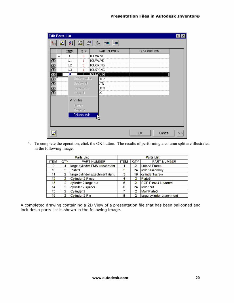
1. Right-click on the Parts List and pick Edit Parts List from the menu.
2. From the Edit Parts List dialog box, pick the row after which the split will occur.
3. Right-click and select Column Split from the menu as shown in the following image.
Presentation Files in Autodesk Inventor®
www.autodesk.com 20
4. To complete the operation, click the OK button. The results of performing a column split are illustrated in the following image.
A completed drawing containing a 2D View of a presentation file that has been ballooned and includes a parts list is shown in the following image.

Presentation Files in Autodesk Inventor®
www.autodesk.com 21
Some material was taken from Daniel T. Banach - Travis Jones – Alan J. Kalameja, Autodesk Inventor 6 Essentials, (c) 2003 Autodesk Press www.autodeskpress.com.