spbt3.0dpx data package - home - stmicroelectronics data package firmware interface overview the dp...
TRANSCRIPT

IntroductionThe data package (DP) is an easy to use AT command set embedded in the SPBT3.0DPx ST Bluetooth® module series. It is auser friendly interface that implements the cable replacement and supports communication with smart phones and MFi devices.
SPBT3.0DPx modules have the DP firmware with SPP, HID and IAP2 (iPOD accessory protocol) services for communicationwith smart phones and Apple iOS Bluetooth enabled devices.
The modules with their embedded DP firmware have been qualified by Bluetooth® SIG. (For more information about QualifiedDesign Listing and product declaration procedure, visit: https://www.bluetooth.com/develop-with-bluetooth/qualification-listing/declare-your-product.)
SPBT3.0DPx data package
UM2077
User manual
UM2077 - Rev 4 - February 2018For further information contact your local STMicroelectronics sales office.
www.st.com
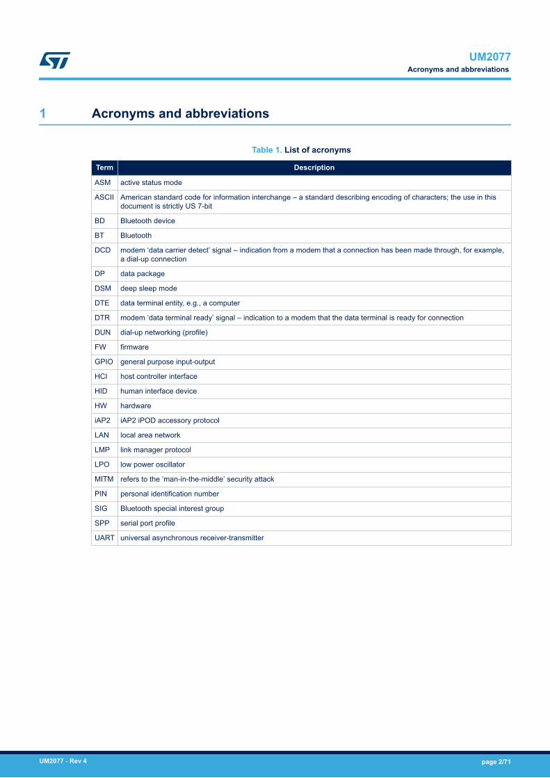
1 Acronyms and abbreviations
Table 1. List of acronyms
Term Description
ASM active status mode
ASCII American standard code for information interchange – a standard describing encoding of characters; the use in thisdocument is strictly US 7-bit
BD Bluetooth device
BT Bluetooth
DCD modem ‘data carrier detect’ signal – indication from a modem that a connection has been made through, for example,a dial-up connection
DP data package
DSM deep sleep mode
DTE data terminal entity, e.g., a computer
DTR modem ‘data terminal ready’ signal – indication to a modem that the data terminal is ready for connection
DUN dial-up networking (profile)
FW firmware
GPIO general purpose input-output
HCI host controller interface
HID human interface device
HW hardware
iAP2 iAP2 iPOD accessory protocol
LAN local area network
LMP link manager protocol
LPO low power oscillator
MITM refers to the ‘man-in-the-middle’ security attack
PIN personal identification number
SIG Bluetooth special interest group
SPP serial port profile
UART universal asynchronous receiver-transmitter
UM2077Acronyms and abbreviations
UM2077 - Rev 4 page 2/71

2 Data package firmware interface overview
The DP firmware is a cable replacement application that provides communication between Bluetooth-enableddevices. A serial port is used to communicate with a host device through an AT command interface as shownbelow.
Figure 1. Communication between module and host
application board
HOSTdevice
(i.e. STM32F4xx)SPBT3.0DPx Bluetooth
devices
The AT command firmware provides:• serial port profile (SPP) support for both client and server applications• iPOD accessory protocol (iAP2) support for communication with Apple iOS Bluetooth-enabled devices• human interface device (HID) profile for keyboard or mouse roles. An HID connection can co-exist with SPP,
or iAP2 connection• command and bypass modes; it is possible to switch between command and bypass (data transmit/receive)
modes during an active connection• security through bonding and data encryption• module low power modes; it is possible to switch between active status mode and deep sleep mode to
reduce power consumption when the module is not connected• BT connection mode; it is possible to set a connection to sniff mode to reduce power consumption
UM2077Data package firmware interface overview
UM2077 - Rev 4 page 3/71

3 Data package command list
The following table lists all the DP commands with links to behavior, syntax, and response details.
Table 2. DP command list summary
Command Description DP version
AbortDiscovery Quit discovery mode 2.1
AutoReconnect Enable/disable auto-reconnect mode 2.0 (1)
AutoReconnectSetup Set auto-reconnect configurationsettings
2.0 (1)
Bond Initiate bonding entry 2.0
BtcVersion BT chip version 2.0
Build Return current firmware build ID number 2.0
Bypass Enter data bypass mode 2.0
CancelConnect Abort connection set-up initiated bymodule
2.2
ChangeBaud Change host interface baud rate 2.0
ChangeDefaultBaud Change the default host interface baudrate
2.0
Config Return/set a configuration variable 2.0
CpTest Test connection with MFi Co-Processor 2.0
DefaultLocalName Change default device local name 2.0
DeleteAutoReconnect Delete auto-reconnect configurationsettings
2.0
DisableBond Disable or deny a bonding with aspecific device
2.0
Discovery Discover and list in range device 2.0
EnableBond Enable bonding with a specific device 2.0
EraseBondTable Erase all the entry from the bondingtable
2.0
ExitSniff Switch device from sniff to normal mode 2.0
Factory Reset factory settings 2.0
FWVersion Return current module FW version 2.0
GetBDAddress Read local BT address 2.0
GetRSSI Get RSSI of current Bluetoothconnection
2.1
GPIOConfig Config GPIO as input or output 2.0 (1)
GPIORead Read GPIO status 2.0
GPIOWrite Set GPIO high or low 2.0
HIDConnect Initiate a HID connection with thespecified device
2.0
HIDDisconnect Close the HID connection 2.0
HIDIntSend Send HID report in interrupt mode 2.0
UM2077Data package command list
UM2077 - Rev 4 page 4/71
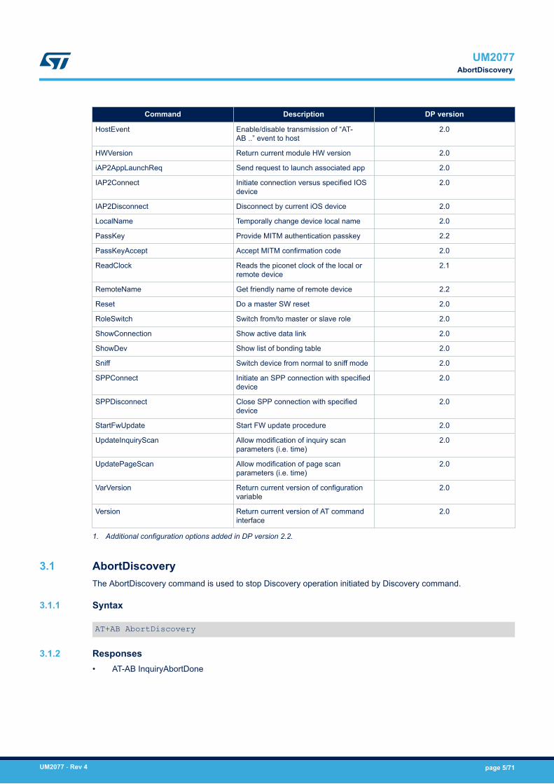
Command Description DP version
HostEvent Enable/disable transmission of “AT-AB ..” event to host
2.0
HWVersion Return current module HW version 2.0
iAP2AppLaunchReq Send request to launch associated app 2.0
IAP2Connect Initiate connection versus specified IOSdevice
2.0
IAP2Disconnect Disconnect by current iOS device 2.0
LocalName Temporally change device local name 2.0
PassKey Provide MITM authentication passkey 2.2
PassKeyAccept Accept MITM confirmation code 2.0
ReadClock Reads the piconet clock of the local orremote device
2.1
RemoteName Get friendly name of remote device 2.2
Reset Do a master SW reset 2.0
RoleSwitch Switch from/to master or slave role 2.0
ShowConnection Show active data link 2.0
ShowDev Show list of bonding table 2.0
Sniff Switch device from normal to sniff mode 2.0
SPPConnect Initiate an SPP connection with specifieddevice
2.0
SPPDisconnect Close SPP connection with specifieddevice
2.0
StartFwUpdate Start FW update procedure 2.0
UpdateInquiryScan Allow modification of inquiry scanparameters (i.e. time)
2.0
UpdatePageScan Allow modification of page scanparameters (i.e. time)
2.0
VarVersion Return current version of configurationvariable
2.0
Version Return current version of AT commandinterface
2.0
1. Additional configuration options added in DP version 2.2.
3.1 AbortDiscoveryThe AbortDiscovery command is used to stop Discovery operation initiated by Discovery command.
3.1.1 Syntax
AT+AB AbortDiscovery
3.1.2 Responses• AT-AB InquiryAbortDone
UM2077AbortDiscovery
UM2077 - Rev 4 page 5/71

3.2 AutoReconnectThis command enables/disables auto-reconnect mode. When enabled, the module tries to open an SPP or iAP2connection automatically with a target device. The parameters of the auto-reconnect mode are configured with theAutoReconnectSetup commands. AutoReconenct status is stored into not volatile memory, so it is kept evenafter reset, or power cycle.
3.2.1 Syntax
AT+AB AutoReconnect [enable/disable]
AT+AB AutoReconnect [enable/disable] [first/last]
Where:[enable/disable] is either:• enable (or e) to enable the auto-reconnect mode• disable (or d) to disable the auto-reconnect mode
[first/last] is either:• 0: First connected device after Enable command is auto-reconnected• 1: Last device connected before reset/power cycle is auto-reconnected
This parameter is optional and available only since DP version 2.2. If not provided it is assumed 0 (first).
3.2.2 ResponsesIf the request is successfully submitted, the response is:• AT-AB AutoReconnectDone Enabled or AT-AB AutoReconnectDone Disabled
3.3 AutoReconnectSetupThis command configures the auto-reconnect parameters, which are stored in non-volatile memory.
3.3.1 Syntax
AT+AB AutoReconnectSetup [interval]
AT+AB AutoReconnectSetup [interval][attempts]
AT+AB AutoReconnectSetup [interval][attempts][BD Address][Type]
Where:[interval] is the pause in seconds between attempts. Note that a page attempt is skipped if there is already aBluetooth activity (discovery, active connection, connection setup) in progress.[attempts] is the number of pages attempted to the specified device until a connection is successful. A value of2000 will perform unlimited pages.[BD Address] is the BD address of the remote device to page and attempt to connect[Type] can be:• “SPP” to indicate an SPP connection• “iAP2” to indicate an iAP2 connection• “HID” to indicate an HID connection (available only since DP version 2.2)
If parameters [BD Address] and [Type] are not specified, the module uses the first or last device thatconnected after the enabling of auto-reconnect.The selection between first or last is provided by Autoreconnect command. If last device mode is selected,autoreconnect will be activated only after reset/power cycle.
UM2077AutoReconnect
UM2077 - Rev 4 page 6/71

3.3.2 ResponsesIf the request is successfully submitted, the response is:• AT-AB AutoReconnectSetupDone
3.4 BondThis command initiates bonding with a specified device. A personal identification number (PIN) is also requiredwith this command. The bond table contains up to 100 devices.The first device after the hundredth overwrites the oldest one on the list.
3.4.1 Syntax
AT+AB Bond [BD Addr] [PIN]
Where:[BD addr] is the BD address of the remote device to bond with[PIN] is the PIN code to use (up to 16 characters)
3.4.2 ResponsesIf the request is successfully submitted, the response is:• AT-AB BondPending [Remote BD Addr]
If the operation is successful, the response is:• AT-AB BondOk
If the operation fails, the response is:• AT-AB BondFail
3.5 BtcVersionThis command returns the current ID of the Bluetooth controller chip.
3.5.1 Syntax
AT+AB BtcVersion
3.5.2 ResponsesIf the embedded BT front end controller is working properly, the response is formatted as:• /00 <HCI_Ver> <HCI_Rev> <LMP_Ver> <Manuf_Name> <LMP_subver>
Table 3. BtcVersion parameter details
Parameter ID Parameter detail Size
<HCI_Ver> HCI version 8 bit
<HCI_Rev> HCI revision 16 bit
<LMP_Ver> LMP ID 8 bit
<Manuf_Name> Manufacturer name 16 bit
<LMP_subver> LMP subversion ID 16 bit
UM2077Bond
UM2077 - Rev 4 page 7/71

3.6 BuildThis command returns the current build ID of the application firmware.
3.6.1 Syntax
AT+AB Build
3.6.2 ResponsesIf the operation is successful, the response is:• AT-AB DataPackage FW Build [date].[M.m.p]
Where:[date] is the date code (yymmdd) of the application firmware[M.m.p] Major FW version, minor FW version and point version
3.7 BypassThis command returns the DP FW interface to bypass mode if a connection is still available. It can be used tochange a setting after a connection has been made (such as the UART baud rate). If the module does not have aconnection, it responds as if the connection were down.
3.7.1 Syntax
AT+AB Bypass
3.7.2 ResponsesIf a connection is still available, the response is:• AT-AB -BypassMode-
If a connection is not available or is closed from the connected device, then the module returns:• AT-AB ConnectionDown
3.8 CancelConnectThis command aborts on-going connection set-up initiated by module.
3.8.1 Syntax
AT+AB CancelConnect
3.8.2 ResponsesIf there is connection attempt running, the response is:• AT-AB SPPConnectionClosed or AT-AB iAP2ConnectionClosed• AT-AB ConnectionDown
If there is no connection attempt running, the response is:• AT-AB ErrExecute no connection attempt running
3.9 ChangeBaudThe host sends the ChangeBaud command to change the local UART rate to a new speed identified by the host.This setting only remains in effect during the current session until reset.
UM2077Build
UM2077 - Rev 4 page 8/71

3.9.1 Syntax
AT+AB ChangeBaud [rate]
Where [rate] is the new baud rate (300, 600, 1200, 2400, 4800, 9600, 19200, 38400, 57600, 115200, 230400,460800, 921600 or 2000000).
3.9.2 ResponsesIf the change is accepted, the response is:• AT-AB Baudrate Changed
The actual change is effective after the response is transmitted. The original baud rate is restored on the followingreboot.If the rate indicated is not one of the above or not usable, the system returns:• AT-AB ERRInvalidParameter
3.10 ChangeDefaultBaudThe host sends the ChangeDefaultBaud command to change the default UART rate to a new speed identified bythe host. This command overrides the default baud rate through the dynamic configuration script, so the devicedoes not require reprogramming to update this setting and the new baud rate applies until the device is either re-programmed or another ChangeDefaultBaud command is issued.The new baud rate does not take effect until the device is reset. To change the baud rate of the current session,use the ChangeBaud command.
3.10.1 Syntax
AT+AB ChangeDefaultBaud [rate]
Where [rate] is the new baud rate (300, 600, 1200, 2400, 4800, 9600, 19200, 38400, 57600, 115200, 230400,460800, 921600 or 2000000).
3.10.2 ResponsesIf the change is accepted, the response is:• AT-AB Baudrate Changed
If the rate indicated is not one of the above or not usable, the system returns:• AT-AB ERRInvalidParamter
3.11 ConfigThis command retrieves or sets a configuration variable.
3.11.1 Syntax
AT+AB Config
with no parameter returns a dump of the variables with corresponding values
AT+AB Config [variable name]
returns the value of the specified variable
AT+AB Config [variable ID]
returns the value of the specified variable ID
UM2077ChangeDefaultBaud
UM2077 - Rev 4 page 9/71
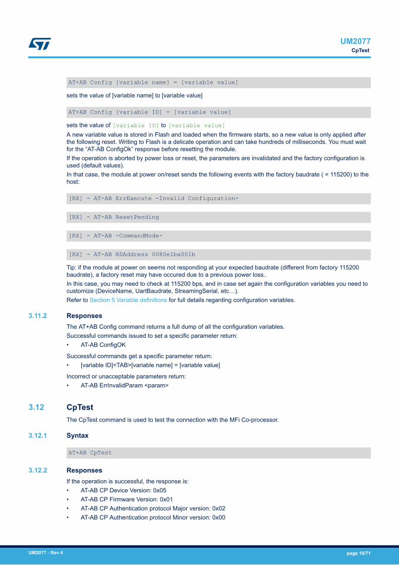
AT+AB Config [variable name] = [variable value]
sets the value of [variable name] to [variable value]
AT+AB Config [variable ID] = [variable value]
sets the value of [variable ID] to [variable value]A new variable value is stored in Flash and loaded when the firmware starts, so a new value is only applied afterthe following reset. Writing to Flash is a delicate operation and can take hundreds of milliseconds. You must waitfor the “AT-AB ConfigOk” response before resetting the module.If the operation is aborted by power loss or reset, the parameters are invalidated and the factory configuration isused (default values).In that case, the module at power on/reset sends the following events with the factory baudrate ( = 115200) to thehost:
[RX] - AT-AB ErrExecute -Invalid Configuration-
[RX] - AT-AB ResetPending
[RX] - AT-AB -CommandMode-
[RX] - AT-AB BDAddress 0080e1ba001b
Tip: if the module at power on seems not responding at your expected baudrate (different from factory 115200baudrate), a factory reset may have occured due to a previous power loss..In this case, you may need to check at 115200 bps, and in case set again the configuration variables you need tocustomize (DeviceName, UartBaudrate, StreamingSerial, etc…).Refer to Section 5 Variable definitions for full details regarding configuration variables.
3.11.2 ResponsesThe AT+AB Config command returns a full dump of all the configuration variables.Successful commands issued to set a specific parameter return:• AT-AB ConfigOK
Successful commands get a specific parameter return:• [variable ID]<TAB>[variable name] = [variable value]
Incorrect or unacceptable parameters return:• AT-AB ErrInvalidParam <param>
3.12 CpTestThe CpTest command is used to test the connection with the MFi Co-processor.
3.12.1 Syntax
AT+AB CpTest
3.12.2 ResponsesIf the operation is successful, the response is:• AT-AB CP Device Version: 0x05• AT-AB CP Firmware Version: 0x01• AT-AB CP Authentication protocol Major version: 0x02• AT-AB CP Authentication protocol Minor version: 0x00
UM2077CpTest
UM2077 - Rev 4 page 10/71

• AT-AB CP Device ID: 0x00000200
If the operation is not successful, the response is:• AT-AB CP Address Fail
3.13 DefaultLocalNameThis command sets the BT Classic name of the device to the name that is reported during device discovery. Bydefault, the DP FW interface uses “STBTC3.0 Module”. This command permanently changes the local name,unlike Section 3.35 LocalName .
3.13.1 Syntax
AT+AB DefaultLocalName [name]
Where [name] is the new, case sensitive, local name string (up to 40 characters). The name is assumed to be alltext up to the end of the command, including spaces.
3.13.2 ResponsesIf the operation is successful, the response is:• AT-AB LocalNameOk
3.14 DeleteAutoReconnectThis command deletes the auto-reconnect configuration settings.
3.14.1 Syntax
AT+AB DeleteAutoReconnect
3.14.2 ResponsesIf the request is successfully submitted, the response is:• AT-AB DeleteAutoReconnectDone
3.15 DisableBondThis command prohibits new bonding with a device; it cannot be used while a connection is active.
3.15.1 Syntax
AT+AB DisableBond
3.15.2 ResponsesIf the operation is successful, the response is:• AT-AB BondDisabled
3.16 DiscoveryThis command initiates device discovery and returns the number (maximum 10) of responses from nearbydevices, followed by the Bluetooth address and name of each responding device.Scanning lasts 10.24 s and devices are listed the same order as the scan results.
UM2077DefaultLocalName
UM2077 - Rev 4 page 11/71

3.16.1 Syntax
AT+AB Discovery
3.16.2 ResponsesWhen the discovery command is accepted, the response is:• AT-AB InqPending
Once the initial inquiry is complete and discovery has started, the response is:• AT-AB DiscoveryPending [num]
where [num] is the decimal number (max. 10) of devices found.For each successful name request, the response uses the returned names thus:• AT-AB Device [BD addr] [name]
where [BD addr] is in hexadecimal with the most significant byte first and [name] is a string in double quotes" ".For each unsuccessful name request, the corresponding name is “Unknown”. The name request may not besuccessful if the connection for the request is unsuccessful.• AT-AB Device [BD addr] "Unknown"
3.17 EnableBondThis command enables bonding with another device.
3.17.1 Syntax
AT+AB EnableBond
AT+AB EnableBond [BD addr]
AT+AB EnableBond [BD addr] [PIN]
AT+AB EnableBond [BD addr] [PIN] [timeout]
Where:[BD addr] is the BD address of the remote device for which bonding is enabled. Set FFFFFFFFFFFF to allowany device.[PIN] is the PIN code (up to 16 characters) used for PIN pairing; not used for simple pairing.[timeout] is the duration in seconds (from 1 to 1000) in which the bond can occur. When the timer expires, thebond is disabled and the AT-AB BondDisabled event is sent to the Host.
3.17.2 ResponsesIf the operation is successful, the response is:• AT-AB BondEnabled
If bonding has been initiated by a remote device, the notification is:• AT-AB BondPending [BD addr]
where [BD addr] is the BD address of the remote device that initiated the bonding. If bonding has occurs, thenotification is:• AT-AB BondOk [BD addr]
where [BD addr] is the BD address of the remote device with successful bonding.If bonding initiated by a remote device fails, the notification is:
UM2077EnableBond
UM2077 - Rev 4 page 12/71

• AT-AB BondFail
3.18 EraseBondTableThis command indiscriminately erases all of the bonded device entries.
3.18.1 Syntax
AT+AB EraseBondTable
3.18.2 ResponsesIf the operation is successful, the response is:• AT-AB BondTableErased
3.19 ExitSniffThis command is used by DP FW to switch an SPP connection with a device from sniff mode to active mode.
3.19.1 Syntax
AT+AB ExitSniff [BD address]
Where [BD address] is the BD address of the device to be switched to active mode.
3.19.2 ResponsesIf the operation is successful, the response is:• AT-AB ActiveMode
3.20 FactoryThis command restores the factory configuration settings.
3.20.1 Syntax
AT+AB Factory
3.20.2 ResponsesIf the request is successfully submitted, the response is:• AT-AB FactoryDone
3.21 FWVersionThis command returns the current DP FW version.
3.21.1 Syntax
AT+AB FWVersion
3.21.2 ResponsesIf the operation is successful, the response is:• AT-AB FWVersion [M.m.p]
UM2077EraseBondTable
UM2077 - Rev 4 page 13/71

Where:[M.m.p] Major FW version, minor FW version and point version
3.22 GetBDAddressThis command reads the Bluetooth device address or MAC address of the local device.
3.22.1 Syntax
AT+AB GetBDAddress
3.22.2 ResponsesIf the operation is successful, the response is:• AT-AB BD_ADDR = [BD address]
3.23 GetRSSIThis command returns RSSI of current Bluetooth connection.
3.23.1 Syntax
AT+AB GetRSSI{BD Addr]
Where [BD Addr] is the BD address of the connected device.
3.23.2 ResponsesIf connected:• AT-AB RSSI Value: [dB value in decimal]
if disconnected:• AT-AB ErrInvalidParam No Connection
3.24 GPIOConfigThe GPIOConfig command is used to configure a GPIO pin to input or output.
3.24.1 Syntax
AT+AB GPIOConfig [GPIO Pin] [Configuration]
AT+AB GPIOConfig [GPIO Pin] [Configuration] [Type]
where [GPIO Pin] is the pin number of the desired GPIO to configure. GPIO numbering depends on thespecific HW used; the valid range is:• For SPBT3.0DP1 1 to 16 if StreamingSerial=TRUE, 1 to 14 if StreamingSerial=FALSE• For SPBT3.0DP2 1 to 10 if StreamingSerial=TRUE, 1 to 8 if StreamingSerial=FALSE
[Configuration] valid values are: ‘I’ or ‘I’ for input and ‘o’ or ‘O’ for output.[Type] The following pin types can be selected with this parameter:a - analogo - open drain outputu - internal pull-up enabledd - internal pull-down enabled
UM2077GetBDAddress
UM2077 - Rev 4 page 14/71

r - interrupt on rising edge - internal pull-down enabledf - interrupt on falling edge - internal resistor disabledrf - interrupt on rising and falling edge - internal resistor disabledWhen interrupt is triggered, the following AT message is sent: AT-AB GPIO XX=0/1GPIO3 cannot be used as interrupt (it clashes with GPIO8)If optional parameter [Type] is not specified than GPIO is configured as:PushPull if outputInput no-pull if input
3.24.2 ResponsesIf the operation is successful, the response is:• AT-AB GPIOConfigDone
If an incorrect parameter is passed to the module, it returns:• AT-AB ErrInvalidParam
3.25 GPIOReadThis command reads a GPIO pin. A GPIO may be read while configured as either an input or output.
3.25.1 Syntax
AT+AB GPIORead [GPIO Pin]
where [GPIO Pin] is the pin number of the desired GPIO to read. GPIO numbering depends on the specific HWused; the valid range is:• For SPBT3.0DP1 1 to 16 if StreamingSerial=TRUE, 1 to 14 if StreamingSerial=FALSE• For SPBT3.0DP2 1 to 10 if StreamingSerial=TRUE, 1 to 8 if StreamingSerial=FALSE
3.25.2 ResponsesIf the operation is successful, the response is:• AT-AB GPIOReadDone [result]
Where [result] is either 1 to indicate high, or 0 to indicate low.If an incorrect parameter is passed to the module, it returns:• AT-AB ErrInvalidParam
3.26 GPIOWriteThis command sets a GPIO pin high or low. A GPIO may only be set when configured as an output.
3.26.1 Syntax
AT+AB GPIOWrite [GPIO Pin] [Setting]
Where:[GPIO Pin] is the pin number of the desired GPIO to write. GPIO numbering depends on the specific HW used.[Setting] is a 1 to set a pin to high and a 0 to set a pin to low.
3.26.2 ResponsesIf the operation is successful, the response is:• AT-AB GPIOWriteDone
UM2077GPIORead
UM2077 - Rev 4 page 15/71

3.27 HIDConnectThe HIDConnect command is used to initiate a HID connection with the specified host device. The remote BDaddress must be specified.
3.27.1 Syntax
AT+AB HIDConnect [BD Addr]
Where [BD Addr] is the remote device’s BD address to connect
3.27.2 ResponsesIf the connection is successful, the response is:• AT-AB HIDConnectionUp
If the connection cannot be completed, the response is:• AT-AB HIDConnectionClosed
3.28 HIDIntSendThe HIDIntSend command is used to send HID reports to the remote hid host.
3.28.1 Syntax
AT+AB HIDIntSend [report]
Where [report] parameter is dependent upon the enabled device type.For Keyboard device [report] is 2 two bytes hex values (4 characters). It is a simplified keyboard that does notsupport setting status LEDs and allow only one simultaneous key press (except modifiers):1st byte: modifiers keys status:Bit0: CTRL Left.Bit1: SHIFT Left.Bit2 : ALT Left.Bit3: GUI Left.Bit4: CTRL Right.Bit5: SHIFT RightBit6: ALT Right.Bit7: GUI Right.Bit value:1 key pressed.0 key released2nd byte: key code specified in Usage Page of USB keyboard (section 10 of document “USB HID usage tables”ver 1.12):www.usb.org/developers/hidpage/Hut1_12v2.pdfExample (press and release Enter key):at+ab hidIntSend 0028at+ab hidIntSend 0000Example (press Shift, then press ’e’, then release both keys):at+ab hidIntSend 0200at+ab hidIntSend 0208at+ab hidIntSend 0000For Mouse device [report] is a 3 bytes hex values (6 characters):
UM2077HIDConnect
UM2077 - Rev 4 page 16/71

1st byte: X axis movement as 2’s complement. (-126, +127). Positive movement is left to right2nd byte: Y axis movement as 2’s complement. (-126, +127). Positive movement is up to down3rd byte: buttons status.Bit0: left button.Bit1: central button.Bit2: right button.Bit3-7: must be 0Bit value:1: button pressed0: button releasedExample (Move pointer right and down by 0x10 pixels. Then left button pressed):at+ab hidIntSend 101000at+ab hidIntSend 000001
3.28.2 ResponsesIf transmission is successful, the response is• AT-AB HIDIntSent
3.29 HIDDisconnectThe HIDDisconnect command is used by DP FW to terminate a connection with the remote host device.
3.29.1 Syntax
AT+AB HIDDisconnect
3.29.2 ResponsesIf the connection is successful, the response is• AT-AB HIDConnectionClosed
3.30 HostEventThis command enables or disables notification to the HOST of all the “AT-AB…” event messages, even responsesto AT commands. That is to emulate a "true cable replacement". Only data received from remote end are sent tothe host.This setting remain in effect during the current session until reset.
3.30.1 Syntax
AT+AB HostEvent [enable/disable]
3.30.2 ResponsesIf the operation is successful, and the parameter was “enable”, the response is:• AT-AB HostEvent Enabled
If the operation is successful, and the parameter was “disable”, there is no response.
3.31 HWVersionThis command returns the current module HW version.
UM2077HIDDisconnect
UM2077 - Rev 4 page 17/71

3.31.1 Syntax
AT+AB HWVersion
3.31.2 ResponsesIf the operation is successful, the response is:• AT-AB HWVersion [M.m]
Where:[M.m] Major HW version, minor HW version
3.32 iAP2AppLaunchReqThis command is used by the DP FW to send the request to the Apple device to launch the App defined with theiAPAppBundleID configuration variable. The iAP2 connection must already be established.
3.32.1 Syntax
AT+AB iAP2AppLaunchReq
3.32.2 ResponseIf the request is sent to the apple device, the response is• AT-AB IAP2AppLaunchDone
If the iAP2 connection is not established, the response is:• AT-AB ErrExecute -iAP2 not connected-
If the iAPAppBundleID configuration variable is invalid, the response is:• AT-AB ErrExecute -Invalid iAPAppBundleID-
3.33 IAP2ConnectThis command is used by DP FW to initiate a connection with the specified Apple iOS device. The remote BDaddress must be specified.
3.33.1 Syntax
AT+AB IAP2Connect [BD Addr]
Where [BD Addr] is the BD address of the iOS remote device to page.
3.33.2 ResponsesIf the connection is successful, the response is:• AT-AB ConnectionUp [Remote BD Addr]• AT-AB -iAP2-BypassMode-
If the connection cannot be completed, the response is:• AT-AB iAP2ConnectionClosed
3.34 IAP2DisconnectThis command is used by DP FW to terminate a connection with the remote Apple iOS device.
UM2077iAP2AppLaunchReq
UM2077 - Rev 4 page 18/71

3.34.1 Syntax
AT+AB IAP2Disconnect
3.34.2 ResponsesIf the connection is successful, the response is• AT-AB iAP2ConnectionClosed
3.35 LocalNameThis command is used to set the name of the device to the name that is reported during device discovery.Changing the name using this command does not permanently change the local name.
3.35.1 Syntax
AT+AB LocalName [name]
Where [name] is a string for the new local name (up to 40 characters). The name is all the text up to the end ofthe command, including spaces.
3.35.2 ResponsesIf the operation is successful, the response is:• AT-AB LocalNameOk
If [name] is not valid (i.e., too long or empty) the following error message is returned:• AT-AB ErrInvalidParam
3.36 PassKeyThis command is used to provide authentication code for MITM protected pairing. The command must be sent asa response to the event AT-AB PassKeyReq (see Section 4.1 AT events) within 40 seconds.
3.36.1 Syntax
AT+AB PassKey [Code]
Where[Code] is a 6 decimal digit code (i.e. 123456)
3.36.2 ResponsesThere is no response. If the operation is successful the module is bonded.
3.37 PassKeyAcceptThis command is used to accept the MITM confirmation code, automatically generated during the bonding phase,when MITM protection is required. In that case this command is necessary to complete pairing.
3.37.1 Syntax
AT+AB PassKeyAccept [y/n]
Example for confirmation:
AT+AB PassKeyAccept y
UM2077LocalName
UM2077 - Rev 4 page 19/71

Example for denying confirmation:
AT+AB PassKeyAccept n
3.37.2 ResponsesThere is no response. If the operation is successful the module is bonded.This command must be sent as a response to the AT-AB PassKeyConfirmReq [PASSKEY] (see Section 4.1 ATevents) within 30 seconds, otherwise the module assumes:
AT+AB PassKeyAccept n
3.38 ReadClockThis command reads the piconet clock of the local or remote device.
3.38.1 Syntax
AT+AB ReadClockAT+AB ReadClock [Remote BDAddress]
3.38.2 ResponseFor local clock:• Clock [Local BDAddress] [clock output in HEX]
For remote clock:• If connected:
– Clock [Remote BDAddress] [clock output in HEX]• if disconnected:
– AT-AB ErrInvalidParam No Connection
3.39 RemoteNameGet friendly name of remote device.
3.39.1 Syntax
AT+AB RemoteName [BD Addr]
Where:[BD Addr] is the BD address of the remote device whose name is requested.If connection is in place, [BD Addr] must be the one of the connected device.
3.39.2 ResponsesIf the operation is successful, the response is:• AT-AB Device [BD Addr] [name]
where [BD Addr] is in hexadecimal with the most significant byte first and [name] is a string in double quotes " ".If the operation is not successful, the response is:• AT-AB Device [BD Addr] "Unknown"
Note: If [BD Addr] is neither in bond table, nor discovery table, a connection to the device is attempted, if not inplace already.In this case, successful operation includes connection/disconnection events:
UM2077ReadClock
UM2077 - Rev 4 page 20/71

• AT-AB ConnectionUp [BD Addr]• AT-AB Device [BD Addr] [name]• AT-AB ConnectionDown
3.40 ResetThis command resets the DP FW interface; it is provided in the event that a host application wants to perform asoftware reset for error recovery. There is a response prior to reset in order to verify that the command wasreceived by the DP FW interface.
3.40.1 Syntax
AT+AB Reset
3.40.2 ResponsesIf the operation is successful, the response is:• AT-AB ResetPending
3.41 RoleSwitchThis command changes a link from/to a master or slave role
3.41.1 Syntax
AT+AB RoleSwitch [bd address][role]
Where [bd address] is the address of the remote device that receives the role switch.[role] is the required device role:0: Master1: Slave
3.41.2 ResponsesIf the operation is successful, the response is:• AT-AB RoleSwitchDone [NewRole]
Where [NewRole] can be master or slave• AT-AB ErrExecute when there is no connection, or connection is in sniff mode
3.42 ShowConnectionThis command is used to display the details of active links.
3.42.1 Syntax
AT+AB ShowConnection
3.42.2 ResponsesReply format with active connection:• Channel ID, Remote Device BD Address, Status, Profile• 0, 4cb199dccd22, Connected, SPP
Reply without active connection:• No Device Connected
UM2077Reset
UM2077 - Rev 4 page 21/71

3.43 ShowDevThis command lists the contents of the bond table.
3.43.1 Syntax
AT+AB ShowDev
3.43.2 ResponsesThis command returns the list of all the bonded devices with their BD address.If the bonding table has no items, it returns:• AT-AB BondTableEmpty
3.44 SniffThis command is used by DP FW to switch the status of the current connection from active mode to sniff mode.
3.44.1 Syntax
AT+AB Sniff [BD address] [Sniff Interval Min] [Sniff Interval Max] [Attempts] [Timeout]
Where:[BD address] is the BD address of the connected device to be switched to sniff mode.[Sniff Interval Min] is the minimum acceptable interval between each consecutive sniff period.[Sniff Interval Max] is the maximum acceptable interval between each consecutive sniff period.Value is given in slots from 2 to 65534. Each slot has duration of 0.625 ms. If not specified, the value ofconfiguration variable AutoSniffIntMax is used.[Attempts] The number of master-to-slave transmission slots during which a device should listen for traffic,from 1 to 32768. If not specified, the value of configuration variable AutoSniffAttempts is used.[Timeout] The amount of time before a sniff radio timeout occurs. Expressed in 1.25 ms increments. Rangebetween 0 and 32768. If not specified, the value of configuration variable AutoSniffRadioTimeout is used.Example sniff command:
at+ab sniff 0CB319BD8270 500 1000 100 50
3.44.2 ResponsesIf the operation is successful, the response is:• AT-AB SniffMode
3.45 SPPConnectThis command initiates a connection with the specified device, specifying the remote BD address. The remoteservice is optional. If not specified, the first registered SPP service is used.
3.45.1 Syntax
AT+AB SPPConnect [BD Addr]
Where [BD Addr] is the BD address of the remote device to page.
3.45.2 ResponsesIf the connection is successful, the response is:
UM2077ShowDev
UM2077 - Rev 4 page 22/71

• AT-AB ConnectionUp [BD Addr]• AT-AB -BypassMode-
If the connection cannot be completed, the response is:• AT-AB SPPConnectionClosed
3.46 SPPDisconnectThis command terminates a connection with the remote device.
3.46.1 Syntax
AT+AB SPPDisconnect
3.46.2 ResponsesIf the connection is successful, the response is:• AT-AB SPPConnectionClosed
3.47 StartFwUpdateThis command can be issued to start the FW update procedure. It is software alternative to using the Boot pin toset the SPBT3.0DPx module in Bootloader mode.
3.47.1 Syntax
AT+AB StartFwUpdate
3.47.2 ResponsesIf the command execution is successful, the response is:• AT-AB Fw Update Started
After sending the response, the module enters Bootloader mode.If the firmware download procedure is not started within 30 seconds, a reset is triggered and the firmware restarts.Refer to the firmware update procedure in the datasheet for details.
3.48 UpdateInquiryScanThe command modifies the inquiry scan parameters: mode, duration and interval.
3.48.1 Syntax
AT+AB UpdateInquiryScan [mode]
AT+AB UpdateInquiryScan [mode] [duration] [interval]
Where[mode] is the discoverable mode:• 0: non-discoverable• 2: discoverable
[duration] is the scan length in slots; 18 to [interval]. The default duration is 18 slots. This parameter isoptional.[interval] is the period between scans in slots; 18 to 4096. The default interval is 2048 slots. This parameteris optional. This parameter is optional.
UM2077SPPDisconnect
UM2077 - Rev 4 page 23/71

The duration of one slot is 0.625 ms.Both optional parameters have to be included or excluded in the command. It is not possible to specify just one ofthe two optional parameter.
3.48.2 ResponsesIf the command is successful, the response is:AT-AB InquiryScanUpdateDone
3.49 UpdatePageScanThe UpdatePageScan command is used to modify the page scan parameters: mode, duration, and interval.
3.49.1 Syntax
AT+AB UpdatePageScan [mode]
AT+AB UpdatePageScan [mode] [duration] [interval]
where [mode] is the connectable mode:• 0: non-connectable• 1: connectable
[duration] is the scan length in slots from 18 to [interval]. The default duration is 18 slots. This parameteris optional.[interval] is the period between scans in slots from 18 to 4096; the default interval is 2048 slots. Thisparameter is optional.The duration of one slot is 0.625 ms.Both optional parameters must either be included or excluded together; you cannot just specify one of the two.
3.49.2 ResponsesIf the command is successful, the response is:• AT-AB PageScanUpdateDone
3.50 VarVersionThis command returns the current version of the DP configuration variable.
3.50.1 Syntax
AT+AB VarVersion
3.50.2 ResponsesIf the operation is successful, the response is:
AT-AB VarVersion [M.m]
Where:[M.m] Major version and minor version of the configurable variable
3.51 VersionThis command returns the current version of the DP AT command interface.
UM2077UpdatePageScan
UM2077 - Rev 4 page 24/71

3.51.1 Syntax
AT+AB Version
3.51.2 ResponsesIf the operation is successful, the response is:• AT-AB DataPackage Ver [M.m]
Where:[M.m] Major version and minor version of the AT command interface.
UM2077Version
UM2077 - Rev 4 page 25/71
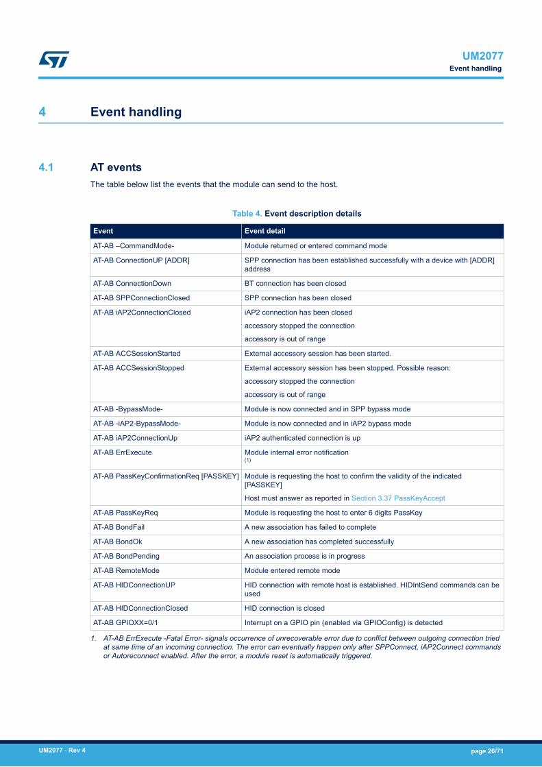
4 Event handling
4.1 AT eventsThe table below list the events that the module can send to the host.
Table 4. Event description details
Event Event detail
AT-AB –CommandMode- Module returned or entered command mode
AT-AB ConnectionUP [ADDR] SPP connection has been established successfully with a device with [ADDR]address
AT-AB ConnectionDown BT connection has been closed
AT-AB SPPConnectionClosed SPP connection has been closed
AT-AB iAP2ConnectionClosed iAP2 connection has been closed
accessory stopped the connection
accessory is out of range
AT-AB ACCSessionStarted External accessory session has been started.
AT-AB ACCSessionStopped External accessory session has been stopped. Possible reason:
accessory stopped the connection
accessory is out of range
AT-AB -BypassMode- Module is now connected and in SPP bypass mode
AT-AB -iAP2-BypassMode- Module is now connected and in iAP2 bypass mode
AT-AB iAP2ConnectionUp iAP2 authenticated connection is up
AT-AB ErrExecute Module internal error notification(1)
AT-AB PassKeyConfirmationReq [PASSKEY] Module is requesting the host to confirm the validity of the indicated[PASSKEY]
Host must answer as reported in Section 3.37 PassKeyAccept
AT-AB PassKeyReq Module is requesting the host to enter 6 digits PassKey
AT-AB BondFail A new association has failed to complete
AT-AB BondOk A new association has completed successfully
AT-AB BondPending An association process is in progress
AT-AB RemoteMode Module entered remote mode
AT-AB HIDConnectionUP HID connection with remote host is established. HIDIntSend commands can beused
AT-AB HIDConnectionClosed HID connection is closed
AT-AB GPIOXX=0/1 Interrupt on a GPIO pin (enabled via GPIOConfig) is detected
1. AT-AB ErrExecute -Fatal Error- signals occurrence of unrecoverable error due to conflict between outgoing connection triedat same time of an incoming connection. The error can eventually happen only after SPPConnect, iAP2Connect commandsor Autoreconnect enabled. After the error, a module reset is automatically triggered.
UM2077Event handling
UM2077 - Rev 4 page 26/71

5 Variable definitions
This section lists the variables handled by the SPBT3.0DPx module to configure the correct behavior for thespecific application scenario.As already mentioned, each variable is accessible via the AT+AB Config command.Variables are saved in internal non-volatile memory and any changed values are loaded on system reset.Below is an example showing a variable change to configure the UART BaudRate:
Table 5. Sample configuration sequence
Direction Command Note
Host TX AT+AB Config UartBaudrate<CR+LF>Read actual UART configuration (115200)
Module TX var7<TAB>UartBaudrate = 115200<CR+LF>
Host TX at+ab config uartbaudrate=921600<CR+LF> Change the UART bit rate to 921600
Module TX AT-AB ConfigOK<CR+LF> Change acknowledgment
Host TX AT+AB Reset<CR+LF> Reset the module. This reloads the new variable value
Module TX AT-AB ResetPending<CR+LF>
Host TX AT+AB Config UartBaudrate<CR+LF> The host has to reconfigure the baud rate to 921600 in order to beable to communicate with the module
Module TX var7<TAB> UartBaudrate = 921600<CR+LF> The new UART baud rate has been applied
If the specified parameter is not listed, an ErrInvalidParam message is returned.
Table 6. List of configuration variables
Variable ID Variable Description Default Var
Var1 BuildVersion BT module buildrevision
2.0
Var3 BD_ADDR BT module MACaddress (read only)
2.0
Var4 DeviceName BT classic device nameshown duringconnection process.
Sequence is casesensitive, maximumlength is 40 characters
ST BTC3.0 module 2.0
Var5 StreamingSerial Allows theconfiguration of theUART flow control.When set to:
TRUE: flow control isdisable
FALSE: flow control(CTS and RTS) isenabled
Note: disabling the flowcontrol may cause dataloss due to dataoverrun
TRUE 2.0
UM2077Variable definitions
UM2077 - Rev 4 page 27/71

Variable ID Variable Description Default Var
Var6 PIN Code used for pairing(4 - 16 characters).
Sequence is casesensitive
1234 2.0
Var7 UartBaudrate Main UART BaudRate:
300, 600, 1200, 2400,4800, 9600, 19200,38400, 57600, 115200,230400, 460800,921600 or 2000000
It should be set basedon the applicationspecific requirements.
This parameter mustbe tuned accordinglywith the CPU frequency(CpuMHz)
115200 2.0
Var8 UartParity Main UART parity. Itmay be configured asone of the following:
NONE
EVEN
ODD
NONE 2.0
Var9 UartDataBits Main UART DataBitsper character. It may beconfigured as either:
8
9
The new configurationis effective after a SWsystem reset or apower cycle isperformed
8 2.0
Var10 UartStopBits Main UART StopBitsper character. It may beconfigured as either:
1
2
The new configurationis effective after a SWsystem reset or apower cycle isperformed
1 2.0
Var12 AutoSniff The AutoSnifffunctionality whenactive, allow thesystem to turn onautomatically the snifffeature when there isno data exchange onthe BT link.
It may be configured aseither:
FALSE
TRUE
FALSE 2.0
UM2077Variable definitions
UM2077 - Rev 4 page 28/71

Variable ID Variable Description Default Var
Var13 AutoSniffTimeout The inactivity timeout inseconds used forAutoSniff above.
If the AutoSniff isenabled, the modulewill try to set the BT linkin sniff mode in casethere has not been anydata exchange forAutoSniffTimeoutseconds.
Acceptable range:1-255
5 2.0
Var14 AutoSniffInterval Minimum acceptableinterval between eachconsecutive sniffperiod. It may be anyeven number between2 and 65534. The valueis expressed in 0.625ms increments (6 =3.75 ms)
500 2.0
Var16 HostDeepSleepEnable Enables/disables thedeep sleep mode(DSM) of the module.
It may be configured aseither:
FALSE
TRUE
See Section 6 Modulepower modes
FALSE 2.0
Var18 GPIO_HostWakeup The GPIO_HostWakeup variableallows the GPIO pin tobe selected and usedto switch betweenmode power modes.
It may be configured asone of the following:
NONE, 2, 3 (*), 7, 8 (*)
See chapter “ModulePower Mode” fordetails.
See GPIO table fordetails
NONE 2.0
UM2077Variable definitions
UM2077 - Rev 4 page 29/71

Variable ID Variable Description Default Var
Var25 CpuMHz CpuMHz allows theCPU clock frequency tobe configured. It maybe configured as:
13, 16, 26, 42, 46, 50,64, 84 or100
Increasing the clockallows betterperformance withhigher powerconsumption.
Decreasing the clockreduces performanceand consequentlypower consumption. Itmust be adjustedaccording to theapplication scenarios
84 2.0
Var30 COD The variable CODallows Bluetooth classof the device to bespecified
Up to 6 numericcharacters are allowed
200404 2.0
Var32 HostEvent All “AT-AB …” hostevents are sent whentrue
TRUE 2.0
Var33 BondingAllowed Enable/disableassociation with otherdevices.
It may be configured aseither:
FALSE: rejects anyassociation request
TRUE: allowsassociation with newdevices
TRUE 2.0
Var34 PageScan Configures the pagescan mode
It may be configured aseither:
FALSE: page scandisabled. The moduleis not connectable.
TRUE: page scanenabled. The module isconnectable.
TRUE 2.0
UM2077Variable definitions
UM2077 - Rev 4 page 30/71
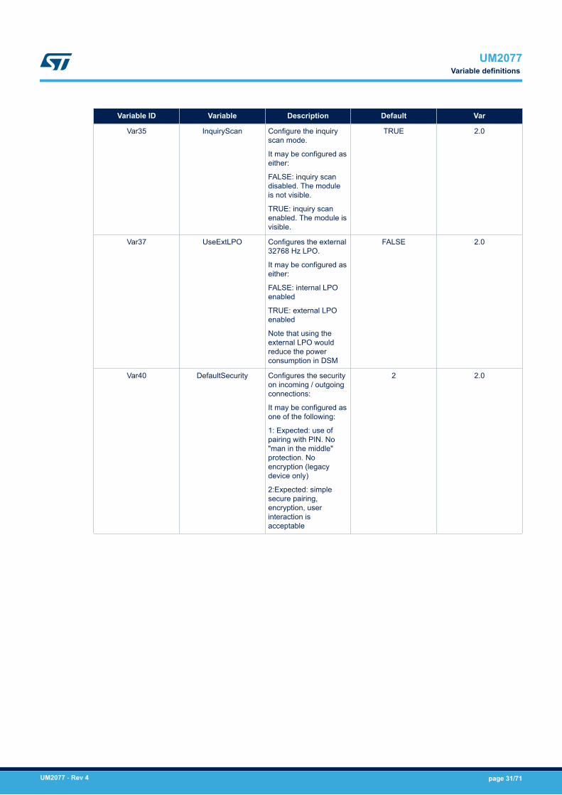
Variable ID Variable Description Default Var
Var35 InquiryScan Configure the inquiryscan mode.
It may be configured aseither:
FALSE: inquiry scandisabled. The moduleis not visible.
TRUE: inquiry scanenabled. The module isvisible.
TRUE 2.0
Var37 UseExtLPO Configures the external32768 Hz LPO.
It may be configured aseither:
FALSE: internal LPOenabled
TRUE: external LPOenabled
Note that using theexternal LPO wouldreduce the powerconsumption in DSM
FALSE 2.0
Var40 DefaultSecurity Configures the securityon incoming / outgoingconnections:
It may be configured asone of the following:
1: Expected: use ofpairing with PIN. No"man in the middle"protection. Noencryption (legacydevice only)
2:Expected: simplesecure pairing,encryption, userinteraction isacceptable
2 2.0
UM2077Variable definitions
UM2077 - Rev 4 page 31/71

Variable ID Variable Description Default Var
Var41 DefaultAuth Configures theauthenticationprocedure based oninput/output capabilitiesof the Bluetooth device.
It may be configured asone of the following:
4: The device is notcapable of input output(pass key confirmationby host disabled)
5: The device candisplay and acceptinput (pass keyconfirmation by hostenable)
6: The device is onlycapable of a display
7: The device is akeyboard with nodisplay
4 2.0
Var42 EnableIAP2 Enables iAP2 tosupport IOS devices
It may be configured aseither:
FALSE: iAP2 supportdisabled
TRUE: iAP2 supportenabled
TRUE 2.0
Var43 AllowSniff Configures the sniffmode.
It may be configured aseither:
FALSE: sniff mode notsupported
TRUE: sniff mode issupported
FALSE 2.0
Var44 iAP2AppID Allows the applicationID to be specified andto be associated to theaccessory
Up to 50 alphanumericcharacters are allowed
“com.yourcompany.yourApp”
2.0
UM2077Variable definitions
UM2077 - Rev 4 page 32/71

Variable ID Variable Description Default Var
Var51 RmtEscapeSequence Enable remote mode:
TRUE: remote modeenabled. Remoteescape sequencedetection logic isenabled.
FALSE: remote modedisabled. Remoteescape sequencedetection logic isdisabled.
The remote escapesequence is “@#@$@%”
FALSE 2.0
Var55 MITMEvent Enables/disables thehost passkey via UART.It may be configured aseither:
FALSE: ifMITMEvent=FALSE atthe other end too,module does notgenerate the Passkeyevents to the host
TRUE: modulegenerates the passkeyevents to the host
FALSE 2.0
Var60 AccManufacturer Configured theaccessorymanufacturer identifierexposed while an iOSdevice is beingconnected.
Up to 20 alphanumericcharacters are allowed
“yourcompany” 2.0
Var61 AccModelNumber Configured theaccessory modelidentifier exposed whilean iOS device is beingconnected.
Up to 20 alphanumericcharacters are allowed
“Your Model” 2.0
Var62 AccSerialNumber Configures theaccessory host deviceserial number exposedwhile an iOS device isbeing connected.
Up to 20 alphanumericcharacters are allowed
“your iAP2 SN” 2.0
UM2077Variable definitions
UM2077 - Rev 4 page 33/71

Variable ID Variable Description Default Var
Var63 EnableSPPRcv Configures thecapability of the host toreceive data thatbelong to the SPPprofile while the moduleis in command mode.
It may be configured aseither:
FALSE: module shouldnot send any data tothe host.
TRUE: module shouldsend received data tothe host.
Note that if the modulesends data to the hostin command mode, thefollowing event is sentbefore the data:
“AT-AB RecvData:”
FALSE 2.0
Var64 EnableIAP2Rcv Configures thecapability of the host toreceive data thatbelong to the iAP2profile while the moduleis in command mode.
It may be configured aseither:
FALSE: module shouldnot send any data tothe host.
A maximum of 4 datapackets are stored andsent out when moduleswitches to bypassmode. If more packetsare received, they aredropped.
TRUE: module shouldsend received data tothe host.
Note that if the modulesends data to the hostin command mode, thefollowing event is sentbefore the data:
“AT-AB RecvData:”
FALSE 2.0
Var65 AccFirmwareVersion Configures theaccessory host devicefirmware version.
Up to 20 alphanumericcharacters are allowed
“your FW version” 2.0
Var66 AccHardwareVersion Configures theaccessory host devicehardware version.
Up to 20 alphanumericcharacters are allowed
“your HW version” 2.0
UM2077Variable definitions
UM2077 - Rev 4 page 34/71

Variable ID Variable Description Default Var
Var67 AccProductID Configures the uniqueidentifier of the product(assigned by vendor).
Unsigned short value tobe provided as hexformat without ‘0x’prefix (i.e. ‘abcd’)
0000 2.0
Var68 AccVersion Configures thesoftware version.
Unsigned short value tobe provided as hexformat without ‘0x’prefix (i.e. ‘abcd’)
0000 2.0
Var69 AccVendorID Sets the vendor ID.
Unsigned short value tobe provided as hexformat without ‘0x’prefix (i.e. ‘abcd’)
0000 2.0
Var70 AccVendorIDSource Configures the identityof the organization thatassigns the vendor IDvalue.
Unsigned short value tobe provided as hexformat without ‘0x’prefix (i.e. ‘abcd’)
0000 2.0
Var72 iAP2AppBundleID Configures IOSapplication associatedto the MFi accessory.
Format is reverse DNSnotation.
To disable the iAP2AppLaunch feature, seta string shorter than 3characters (i.e., "a")
"com.yourcompany.yourApp"
2.0
Var73 CPI2CAddress Configures the I2Caddress of the CPdevice as unsignedchar hex format.
Unsigned short value tobe provided as hexformat without ‘0x’prefix (i.e. ‘ab’)
22 2.0
Var74 EnableUARTbreak Enables/disables theUART break to switchfrom ByPass toCommand mode
FALSE 2.0
UM2077Variable definitions
UM2077 - Rev 4 page 35/71
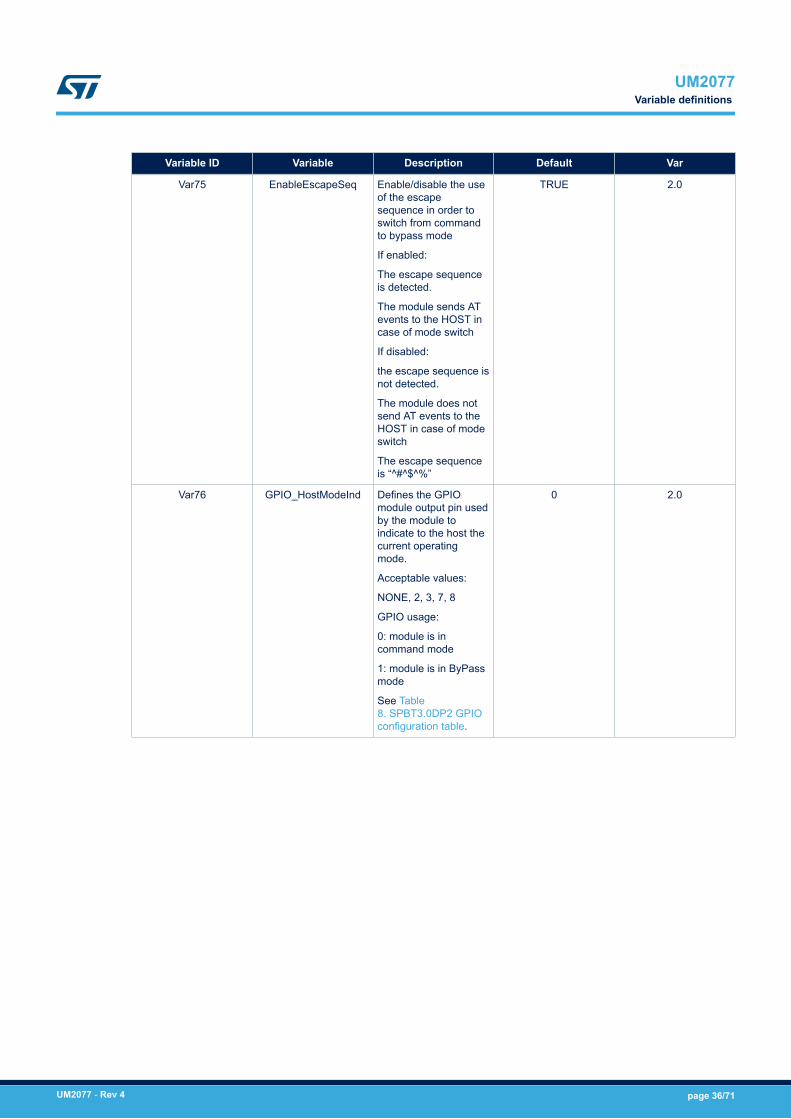
Variable ID Variable Description Default Var
Var75 EnableEscapeSeq Enable/disable the useof the escapesequence in order toswitch from commandto bypass mode
If enabled:
The escape sequenceis detected.
The module sends ATevents to the HOST incase of mode switch
If disabled:
the escape sequence isnot detected.
The module does notsend AT events to theHOST in case of modeswitch
The escape sequenceis “^#^$^%”
TRUE 2.0
Var76 GPIO_HostModeInd Defines the GPIOmodule output pin usedby the module toindicate to the host thecurrent operatingmode.
Acceptable values:
NONE, 2, 3, 7, 8
GPIO usage:
0: module is incommand mode
1: module is in ByPassmode
See Table8. SPBT3.0DP2 GPIOconfiguration table.
0 2.0
UM2077Variable definitions
UM2077 - Rev 4 page 36/71

Variable ID Variable Description Default Var
Var77 GPIO_HostModeSel Defines the GPIOmodule input pin thatcan be used by thehost to select theoperating mode(Command or ByPassmode):
GPIO usage:
Falling edge: ifapplicable, switch fromByPass to commandMode
Rising edge: ifapplicable, switch fromcommand to ByPassmode
See Table8. SPBT3.0DP2 GPIOconfiguration table andTable 9. SPBT3.0DP1GPIO configurationtable for the list ofacceptable values.
NONE 2.0
Var78 EnableUartBreakInd Controls enabling ofUART break asindication to the host ofbypass/commandmode switch
FALSE 2.2
Var79 User_Flag Provides hostapplication non-volatile1 byte storage
FALSE 2.2
Var80 User_Data Provides hostapplication non-volatile40 characters stringstorage
Your private data 2.2
Var86 EnableSPPSrv Enables the SPPservice.
It may be configured asone of the following:
FALSE: SPP servicedisable
TRUE: SPP serviceenable
TRUE 2.0
Var87 iAP2TeamID Configures the MFiteam ID associated tothe app.
Up to 50 alphanumericcharacters are allowed
“Your Team ID” 2.0
Var88 EnableHIDKeybd Controls enabling ofHID keyboard profile
FALSE 2.0
Var89 EnableHIDMouse Controls enabling ofHID mouse profile
FALSE 2.0
UM2077Variable definitions
UM2077 - Rev 4 page 37/71

Variable ID Variable Description Default Var
Var91 AutoSniffIntMax Maximum acceptableinterval between eachconsecutive sniffperiod.
May be any evennumber between0x0002 and 0xFFFEThe value is expressedin 0.625 ms increments(0x0006 = 3.75 ms)
1000 2.0
Var92 AutoSniffAttempts The number of master-to-slave transmissionslots during which adevice should listen fortraffic (sniff attempt).Expressed in 0.625 msincrements. Rangebetween 0x0001 and0x7FFF
100 2.0
Var93 AutoSniffRadioTimeout The amount of timebefore a sniff radiotimeout occurs.Expressed in 1.25 msincrements. Rangebetween 0x0000 and0x7FFF
20 2.0
Var94 GPIO_FactoryReset Enables the factoryreset of theconfiguration variablesusing the GPIO8 pin.When TRUE, if GPIO8is high at next reset,factory configuration isrestored. If this functionis needed, it issuggested to enable itat first power-on of themodule
FALSE 2.1
Var95 UartRxPullUp Enables 1.8 V pull-upon the module UARTRx pin. It can bedisabled in case thehost UART tx pin levelis higher than 1.8 V
TRUE 2.1
Var96 UartTxOD Manages UART Tx andRTS pins outputconfiguration.
TRUE: open drain
FALSE: push-pull
Note that open drainconfiguration allowsadjustment of theUART tx output signallevel to host logic withexternal pull-up withoutrequiring the levelshifter. Maximumtested speed is 115200baud rate with 4.7 kpull-up to 3.3 V
FALSE 2.1
UM2077Variable definitions
UM2077 - Rev 4 page 38/71

5.1 Variables dependencySome variable correct setting is dependent of the setting of another variable.The list of interdependent variables as follows:• MITMEvent vs DefaultAuth: if DefaultAuth=4, MITMEvent must be FALSE• EnableHIDKeybd vs EnableHIDMouse: If EnableHIDMouse=TRUE, EnableHIDKeybd must be FALSE
CPUMHz vs. UartBaudrate: the following table shows the allowed CPUMHz values with respect to baud rate:
Table 7. CPUMHz vs. baud rate
Baud rate CPUMHz
Min.
CPUMHz
Max.
300 13 16
600 13 26
1200 13 64
2400 13 84
4800 13 100
9600 13 100
19200 13 100
38400 13 100
57600 13 100
115200 13 100
230400 13 100
460800 13 100
921600 16 100
2000000 42 100
UM2077Variables dependency
UM2077 - Rev 4 page 39/71

6 Module power modes
The SPBT3.0DPx module has the following power modes:1. active status mode (ASM) (default mode)2. deep sleep mode (DSM)DSM mode can only be entered when there is no Bluetooth connection or discovery, pairing, or scanning activityin progress.When the module is in DSM:• the AT command interface is not active
GPIO_4 indicates the current module power mode:• 0: indicates that the module is in DSM mode• 1: indicates that the module is in ASM mode
6.1 Enable deep sleep modeTo enable the DSM, the GPIO_HostWakeUp and HostDeepSleepEnable variables have to be set. Refer to thetables below for the list of GPIOs that can be used as GPIO_HostWakeUp.
/* define the module GPIO to be used by the HOST to enter /exit DSM mode */
AT+AB config GPIO_HostWakeUp = 3
/* enable the DSM mode*/
AT+AB config HostDeepSleepEnable = TRUE
6.2 Host forcing the module to enter DSMTo request the module to enter DSM, the HOST must force the GPIO_HostWakeUp pin LOW.
6.3 Host forcing the module to exit DSMTo set the module in ASM, the HOST must force the GPIO_HostWakeUp pin HIGH.If the module is in DSM mode and the HOST wants to send an AT command, the module must first be switched toASM mode.
6.4 Module exit DSM autonomouslyThe module automatically exits DSM if there is a Bluetooth connection or upon discovery, pairing, or scanningactivity.
Note: If both inquiry scan and page scan are disabled, module cannot exit DSM autonomously. In this case watchdogresets the module after 5 seconds. To avoid watchdog reset, host should wake up the module cyclically with aperiod smaller than 5 seconds.
UM2077Module power modes
UM2077 - Rev 4 page 40/71

7 BT connection modes
As defined by the SIG, a Bluetooth connection can be set in either:1. Active mode2. Sniff modeWhen a connection is established, it is in active mode by default, but it is possible to exchange data in bothmodes.To reduce power consumption both the master and the salve can try to set the connection into sniff mode. Bothmaster and slave should support sniff mode otherwise the link always remains in active mode.
7.1 Switch to sniff mode automaticallyTo automatically set a BT link to sniff mode, set the following variables thus:
AT+AB config AutoSniff = TRUE
AT+AB config AllowSniff = TRUE
AT+AB Config AutoSniffTimeout = 5
The module automatically issues a request to switch the Bluetooth link to sniff mode after AutoSniffTimeoutseconds of inactivity.
7.2 Switch to sniff mode manuallyWhen a connection is established, the HOST can send the “AT+AB Sniff” command to request setting the link tosniff mode.To manually set a BT link to sniff mode, the following variable should be set:
AT+AB config AllowSniff = TRUE
7.3 Switch to active mode manuallyWhen a connection is in sniff mode, the HOST can send the “AT+AB ExitSniff” command to switch the link toactive mode.
7.4 Variables affecting sniff modeFew other variables setting must be considered for sniff mode:• HostDeepsleepEnable=TRUE reduces power consumption in sniff mode• If CPUMHz < 42 MHz, sniff mode works only if UseExtLPO=TRUE
UM2077BT connection modes
UM2077 - Rev 4 page 41/71

8 Module operating modes
The module has the following operating modes:1. Command mode: the module is ready to handle AT commands received from the host. This is the default
mode after power on.2. Bypass mode: the module is connected and acts as serial cable replacement. Any data received from the
host is sent to the remote device. Any data received form the remote device is transmitted to the host.3. Remote mode: the module is connected and is ready to handle AT commands received from the remote
device. Remote mode is available only over SPP connection, not over iAP2 connection.An operating mode switch can be requested by the host, by the remote device or can be autonomously initiatedby the module in case of Bluetooth activity (link establishment, link closure, link drop).The host requests an operating mode switch by:1. Using the AT command interface (commands or EscapeSequence)2. Using the GPIO_HostModeSel GPIO3. Using the UART breakThe module can notify the host of a mode switch by:1. Using the AT command interface2. Using the GPIO_HostModeInd GPIO3. Using the UART breakThe remote device can request the switch to remote mode by:1. Sending the remote escape sequenceThe AT command interface is the default method used. To disable usage of the escape sequence to switch frombypass to command mode, configure the following variable thus:
AT+AB config EnableEscapeSeq = FALSE
To use the GPIO method, configure the GPIO_HostModeSel and GPIO_HostModeInd variables thus:
AT+AB Config GPIO_HostModeSel = 2
AT+AB Config GPIO_HostModeInd = 3
To use the UART break symbol method for the host to request bypass to command mode switch, configure the EnableUartBreak variable thus:
AT+AB Config EnableUartBreak = true
To use the UART Break symbol method, as bypass to command mode switch indication to the host, configure theEnableUartBreakInd variable thus:
AT+AB Config EnableUartBreakInd = true
Break duration is the STM32F4 UART supported one: 10 bits for 1 stop bit, 11 bits for 2 stop bits.All the above methods can be used in a non-exclusive manner. The following sections describe how to switchbetween modes.
8.1 Command to bypass mode switchA command to bypass mode switch can be:1. initiated by the module:
a. when an SPP or iAP2 session is opened2. initiated by the host:
UM2077Module operating modes
UM2077 - Rev 4 page 42/71

a. with the “AT+AB Bypass” commandb. with the GPIO_HostModeSel ( transition from low to high )
8.2 Bypass to command mode switchA command to bypass mode switch can be:1. initiated by the module:
a. when an SPP or iAP2 session is closed2. initiated by the HOST:
a. with the escape sequence (“^#^$^%”)b. with the GPIO_HostModeSel (transition from high to low )c. sending the UART break symbol
When requested by the host, the switch occurs after two seconds of inactivity; i.e., no data exchanged over UARTinterface. However, when the host is using the GPIO_HostModeSel pin (list item 2.b.) with the EnableEscapeSeqset to FALSE, the operating mode switch is immediate. Whit EnableEscapeSeq=FALSE andEnableUartBreak=TRUE, if the UART break used is very long, it is recommended to use a "dummy" invalidcommand after sending the break, to re-align module UART receiver. The answer to dummy invalid command (i.e.Dummy" ) is "AT-AB ErrFormat".
8.3 Bypass to remote mode switchA bypass to remote mode switch can occur in the following cases:1. The remote device sends the remote escape sequence (“@#@$@%”)
8.4 Remote to bypass mode switchA remote to bypass mode switch can occur in the following cases:1. The remote device sends the AT+AB ByPass command2. The HOST sends any data to the module
UM2077Bypass to command mode switch
UM2077 - Rev 4 page 43/71

9 SPBT3.0DP2 module GPIO configuration
The table below shows the functions that can be associated with each module GPIO.
Table 8. SPBT3.0DP2 GPIO configuration table
Module GPIO Default function Alternate function
1 Connection status probe
0: BT connection down
1: BT connection up
GPIO input
2 GPIO input GPIO output
GPIO_HostModeSel
GPIO_HostWakeUp
3 GPIO input GPIO output
GPIO_HostModeInd
4 Active status probe
1: active status mode
Blinking: deep sleep mode
GPIO input
5 I2C SDA GPIO input
GPIO output
6 I2C SCL GPIO input
GPIO output
7 GPIO input GPIO output
GPIO_HostModeInd
GPIO_HostWakeUp
8 GPIO input GPIO output
GPIO_HostModeSel
9 (1) GPIO input GPIO output
10 (1) GPIO input with internal pull-down GPIO output
1. Available only with the firmware version > 1.1, when variable StreamingSerial=TRUE.
UM2077SPBT3.0DP2 module GPIO configuration
UM2077 - Rev 4 page 44/71

10 SPBT3.0DP1 module GPIO configuration
The table below shows all the possible functions that can be associated to each GPIO of the module.
Table 9. SPBT3.0DP1 GPIO configuration table
Module GPIO Default function Alternate function
1 Connection status probe
0: BT connection down
1: BT connection up
GPIO input
2 GPIO input GPIO outputGPIO_HostModeInd
3 GPIO input GPIO output
4 Active status probe
1: Active status mode
Blinking: deep sleep mode
GPIO input
5 GPIO input GPIO output
GPIO_HostWakeUp
6 GPIO input GPIO output
GPIO_HostModeSel
7 GPIO input GPIO output
8 GPIO input GPIO output
GPIO_HostModeSel
9 GPIO input GPIO output
GPIO_HostModeInd
10 GPIO input GPIO output
GPIO_HostWakeUp
11 I2C SCL GPIO input
GPIO output
12 I2C SDA GPIO input
GPIO output
13 GPIO input GPIO output
14 GPIO input GPIO output
15(1)
GPIO input GPIO output
16(1)
GPIO input with internal pull-down GPIO output
1. Available only with firmware version > 1.1, when variable StreamingSerial=TRUE.
UM2077SPBT3.0DP1 module GPIO configuration
UM2077 - Rev 4 page 45/71

11 Secure simple pairing
The SPBT3.0DPx module provides configurable pairing modes, allowing different device input/output capabilitiesto be adapted and to require the security level (MITM protection).The configuration variables that affect pairing (bonding) process are:• Var40 DefaultSecurity• Var41 DefaultAuth• Var55 MITMEvent
The general rules that affect the resulting pairing mode:• DefaultSecurity=1 on one side forces PIN pairing• MITMEvent=FALSE on both side results in “Just Works” pairing, independent of the DefaultAuth value• MITMEvent=TRUE on one side forces MITM protected pairing independent of MITMEvent setting on the
other side• DefaulthAth=4 forces “Just Works” pairing
The following tables summarize the resulting simple pairing mode between two modules during the bondingprocess, with DefaultSecurity=2.Module in configuration DefaultAuth=5, MITMEvent=TRUE is typically equivalent to a smart BT device (PC,phone, tablet ..)Legenda:JW: just worksNC: numeric comparison (event “AT-AB PassKeyConfirmationReq”)PE: passkey entry (event “AT-AB PassKeyReq”)NV: not valid configurarion. DefaultAuth=4 (No input / No output) by definition cannot support MITM protection(MITMEvent=TRUE), that requires user interaction.
Table 10. SPBT3.0DP DisplayYesNo (DefaultAuth=5) and MITMEvent=FALSE
MITMEvent DefaultAuth
4 5 6 7
FALSE JW JW JW JW
TRUE NV NC NC PE
Table 11. SPBT3.0DP DisplayYesNo (DefaultAuth=5) and MITMEvent=TRUE
MITMEvent DefaultAuth
4 5 6 7
FALSE JW NC NC PE
TRUE NV NC NC PE
Table 12. SPBT3.0DP DisplayOnly (DefaultAuth=6) and MITMEvent=FALSE
MITMEvent DefaultAuth
4 5 6 7
FALSE JW JW JW JW
TRUE NV NC NC PE
UM2077Secure simple pairing
UM2077 - Rev 4 page 46/71

Table 13. SPBT3.0DP DisplayOnly (DefaultAuth=6) and MITMEvent=TRUE
MITMEvent DefaultAuth
4 5 6 7
FALSE JW NC JW PE
TRUE NV NC JW PE
Table 14. SPBT3.0DP KeyboardOnly (DefaultAuth=7) and MITMEvent=FALSE
MITMEvent DefaultAuth
4 5 6 7
FALSE JW JW JW JW
TRUE NV PE JW PE
Table 15. SPBT3.0DP KeyboardOnly (DefaultAuth=7) and MITMEvent=TRUE
MITMEvent DefaultAuth
4 5 6 7
FALSE JW PE PE PE
TRUE NV PE PE PE
Table 16. SPBT3.0DP NoINoO (DefaultAuth=4) and MITMEvent=FALSE
MITMEvent DefaultAuth
4 5 6 7
FALSE JW JW JW JW
TRUE NV JW JW JW
UM2077Secure simple pairing
UM2077 - Rev 4 page 47/71

12 Module I/O levels
SPBT3.0DPx module is internally supplied by a voltage regulator at 1.8 V, that means the module I/O levels arereferred to this voltage. When standard pins (not 5 V tolerant) are used to interface other parts of applicationboard at different voltages compared to 1.8 V, a voltage level shifter circuit may be necessary. Refer toSPBT3.0DPx datasheet to identify standard pins.Consider typical case of interfacing 3.3 V +/- 0.3 V logic circuitry.
12.1 Standard pin used as outputOutput high level is limited to 1.8 V, that could be not enough to guarantee the input high level VIH of the circuitthat interface the module. Based on the supply voltage used, a verification is recommended.
12.2 Standard pin used as inputThe voltage must be scaled down in order to guarantee the logic levels do not to exceed the maximum values:1.3 V < VIH < = 1.8 + 0.4 V0 < VIL < 0.5 VA level shifter or a resistor divider with 3.6 / 1.8 = 2 ratio can be used.Value of resistors must be chosen compromising the maximum frequency of the input signal, and currentconsumption.
12.3 Reset pinVoltage at Reset pin must be limited to 1.8 V + 0.4 V when driven by an external active output. If the externalsignal exceed the allowed value a solution must be implemented to limit the input voltage level.• Use an open drain or open collector to drive the reset pin• Use a series resistor to limit the injected current. For 3.3 V a resistor in the range of 6.8 k -10 k• Use a resistor divider taking care that, in worst condition, VIH > 2 V• Put a Schottky diode in series to the reset line and check that the low level logic is < 0.8 V
UM2077Module I/O levels
UM2077 - Rev 4 page 48/71

13 Firmware upgrade
The SPBT3.0DPx modules leverage the STM32 built-in bootloader to load the new firmware. It is a three-stepprocedure:• Enter bootloader mode• Transfer the new firmware• Exit bootloader mode
13.1 Enter bootloader modeTo enter the Bootloader mode two options are available.Via BOOT0 pin:• Set the BOOT0 pin to HIGH level• Reset the module:
– Set the RESET pin to HIGH– Pause– Set the RESET pin to LOW
Via AT Command:• Send over module UART command “at+ab StartFwUpdate<CR><LF>”
13.2 Transfer the new firmwareThe specification of the protocol used in the STM32 bootloader to download the new firmware is described in thedocument:http://www.st.com/web/en/resource/technical/document/application_note/CD00264342.pdfA reference implementation of the STM32 bootloader protocol can be found at the following link:http://sourceforge.net/projects/stm32flash/The STM32 Flash loader demonstrator, a Windows GUI that implement that protocol can be downloaded at thefollowing link:http://www.st.com/en/development-tools/flasher-stm32.html
13.3 Exit bootloader modeTo exit Bootloader mode:• Set the BOOT0 pin to LOW or leave it floating• Reset the module:
– Set the RESET pin to HIGH– Pause– Set the RESET pin to LOW
13.4 Using STEVAL-BT3.0DPxIn case of STEVAL-BT3.0DPx USB dongle for Bluetooth SPBT3.0DPx module, the three steps above can bedone this way:• Enter bootloader mode:
– Plug the USB dongle into the PC USB port– Insert a jumper on JP1– Push the SW1 reset button
If serial console available on PC, it is possible to send command:
UM2077Firmware upgrade
UM2077 - Rev 4 page 49/71

“at+ab StartFwUpdate<CR><LF>”In this case it is not necessary to insert a jumper on JP1.• Transfer the new file:
– Launch the ST Flash Loader Demonstration GUI (version has to be >= 2.7.0) http://www.st.com/en/development-tools/flasher-stm32.html
– Program the new file with the GUI• Exit bootloader mode:
– Remove the jumper on JP1– Push the SW1 reset button
UM2077Using STEVAL-BT3.0DPx
UM2077 - Rev 4 page 50/71

14 iAP2 sample connection
14.1 MFi coprocessor communicationThe MFi coprocessor is connected to the module through the I²C interface. Refer to the module datasheet for areference schematic diagram.You can test I²C communication using the command CPTest. If the response is “AT-AB CP Address Fail”, youneed to change MFi chip I²C address stored in the variable “CPI2CAddress”. Its default value is 22 (hex):
[TX] - AT+AB CPTest[RX] - AT-AB CP Address Fail[TX] - at+ab config CPI2CAddress = 20[RX] – AT-AB ConfigOK[TX] - at+ab resetAT-AB ResetPending::[TX] - AT+AB CPTest[RX] - AT-AB CP Device Version: 0x05[RX] - AT-AB CP Firmware Version: 0x01[RX] - AT-AB CP Authentication protocol Minor version: 0x00[RX] - AT-AB CP Device ID: 0x00000200
14.2 EADemo sample appExternal Accessory demo application source code is available from Apple after obtaining the MFi license fromApple. You can compile and install it on your Apple device.On the module side (accessory), you must set the iAP2AppID configuration variable with the App name:
[TX] - at+ab config iAP2AppID = com.yourcompany.EADemo[RX] - AT-AB ConfigOK[TX] - at+ab reset[RX] - AT-AB ResetPending
14.3 Bluetooth Accessory connection from Apple deviceIn the BT settings menu, connect to the SPBT3.0DPx module.On the module UART control port, the following messages are sent out:
[RX] - AT-AB ConnectionUp CC29F5175A17[RX] - AT-AB BondPending[RX] - AT-AB BondOk CC29F5175A17[RX] - AT-AB iAP2ConnectionUp CC29F5175A17
Manually launch the EADEmo App. In the App menu, from the connected device list, select the SPBT3.0DPxmodule to open an iAP2 External Accessory Session.On the module UART control port, the following messages are sent out:
[RX] - AT-AB AccSessionStarted[RX] - AT-AB -iAP2-BypassMode
UM2077iAP2 sample connection
UM2077 - Rev 4 page 51/71

14.4 EADemo app automatic launchThe iAP2 accessory protocol allows automatic launching of the corresponding application on your Apple device.To use this feature, you need set the iAP2AppBundleID variable to define the App to be launched.
[TX] - at+ab config iAP2AppBundleID = com.alpwise.EADemo [RX] - AT-AB ConfigOK[TX] - at+ab reset[RX] - AT-AB ResetPending::
Connect to the SPBT3.0DPx module, as described previously.Instead of launching the EADemo app manually, you can trigger it from accessory with a user action (i.e., bypressing a button on accessory). The user action must trigger the generation of the following AT command:
[TX] - AT+AB iAP2AppLaunchReq[RX] - AT-AB IAP2AppLaunchDone
The iAP2 external accessory session can now be started from the App menu.
Note: If the iAP2 App launch feature is not used, disable it. To disable it, the iAP2AppBundleID configuration variableshould be set with a string shorter than 3 characters:
[TX] - at+ab config iAP2AppBundleID = a[RX] - AT-AB ConfigOK[TX] - at+ab reset[RX] - AT-AB ResetPending::
This is important for Apple MFi certification as the test checks whether the feature is enabled or disabled.
14.5 MFi certification for Bluetooth accessoriesATS (Accessory Test System) is a toolset available from Apple after obtaining the MFi license. The toolset allowsiAP2 protocol conformance testing in your lab, before sending your equipment to Apple labs for MFi certification.
Important: ATS self-test must be passed before applying for full final certification.
The toolset includes a Bluetooth sniffer to capture traffic between an accessory and an Apple device. It is stronglysuggested to perform test in an RF-free environment to avoid sniffer lost packets due to RF interference.Other recommendations for Apple MFi tests include:1. Customize all the configuration variables related to iAP2 External Accessory (their names start with “Acc…”:
Var60, Var61, Var62, Var65, var66, Var67, Var68, Var69, Var70).2. In particular, set the AccSerialNumber variable with the serial number as indicated in the label of your
product.3. If the iAP2 App launch feature is used, it has to be started by a user action (e.g., a button push).4. If the iAP2 App launch feature is not used, disable it by setting the iAP2AppBundleID configuration variable
with a string shorter than 3 characters ( i.e. “at+ab config iAP2AppBundleID = a”)
UM2077EADemo app automatic launch
UM2077 - Rev 4 page 52/71

15 AT commands for regulatory testing
HCI testing commands are required to set the SPBT3.0DPx module into proper status to perform RF regulatorycertification tests.That is achieved using special AT command “AT+AB SendHCI”.
15.1 TxRx test commandThis command is used to transmit or receive data packets without having a Bluetooth connection.In TX test mode, the device will transmit packets without whitening, according to the specified parameters. This issimilar to the transmitter tests in the Bluetooth Test Mode chapter of the Bluetooth Specification, but the device ismaster.In RX test mode the device will put itself in a packet receive mode, where the packets are expected to arrive on asingle, fixed frequency. When in TX or RX test mode, the Host can send the command again to change theparameters or to end the test mode. It is not allowed to switch on the fly between TX and RX mode, without firstexiting the current scenario.Purpose:To verify the radio TX performance, by sending out Bluetooth packets that will be captured by a test device (e.g.spectrum analyzer).To verify the radio interoperability between two Bluetooth devices. Before starting the test, both devices mustagree on the used Test_Scenario, Frequency, Interval, Packet_Type, Data_Length, BD_Address and LT_Address.These must be applied at both sides.
15.1.1 Syntax
AT+AB SendHCI F4FC1C80808080[Test Scenario][Hopping Mode][Channel]00[Packet Type][Payload Bytes][BD address]01[Channel Map]
Where:[Test Scenario]: (1 byte)• Transmitter tests:
– 0x01: TX pattern 0– 0x02: TX pattern 1– 0x03: TX pattern 1010– 0x04: TX pattern PRBS (random)– 0x09: TX pattern 11110000
• Receiver tests:– 0x0A: Rx pattern 1010– 0x0B: Rx pattern PRBS (random – PRBS9, seed 0x1FF)– 0x0C: Rx pattern 11110000
• 0xFF: Exit Test - use this value to stop a transmission before switching to a new test command
[Hopping Mode]: (1 byte)• 0x00: single frequency• 0x01: standard hopping - Europe (only possible in Tx Test mode)• 0x05: reduced hopping (only possible in Tx Test mode)
[Channel]: (1 byte)• Channel: 0x00 to 0x4E (from 2402 to 2480 MHz). This is used only if Hopping Mode is set to 0x00 Single
Frequency
[Packet Type]: (1 byte)• DH1:0x84
UM2077AT commands for regulatory testing
UM2077 - Rev 4 page 53/71

• DH3: 0x8B• DH5: 0x8F• 2DH1: 0x94• 2DH3: 0x9A• 2DH5: 0x9E• 3DH1: 0xA8• 3DH3: 0xAB• 3DH5: 0xAF
[Payload Bytes]: (2 bytes, little endian)• 0x00 – 0x3fd (0-1021) MUST be smaller or equal to the maximum payload of the packet type selected
For example for DM1 use 18, that is 0x12, in little endian on 2 bytes is 0x1200.For example for DM1 use 341, that is 0x155, in little endian on 2 bytes is 0x5501.[BD Address]: (6 bytes)• BD_Address of the transmitting device. Not used for TX test. Use 0x000000E18000
[Channel Map]: (10 bytes, little endian)• b0 - b78: Mask to enable transmission of each channel. Used only in case Hopping Mode is set to Reduced
Hopping
b79: not used. Leave it to 0.Examples:to enable hopping only on the first 4 channels (from 2402 to 2405 MHz), the channel map should be0x0000000000000000000F, that in little endian is 0x0F000000000000000000.to enable hopping only on the last 3 channels (from 2477 to 2480 MHz), the channel map should be0x70000000000000000000, that in little endian is 0x00000000000000000070.
15.1.2 ResponsesIf the command is successful, the response is:• AT-AB CommandComplete: 0e 04 02f4fc00
15.1.3 TxRx_Test command examplesCommand:
at+ab sendhci F4FC1C80808080020100008F5301000000E1800001FFFFFFFFFFFFFFFFFF7F
• Test Scenario: TX pattern 1• Hopping Mode: Standard Hopping - Europe, 0x01• Frequency: 0x00• Packet Type: DH5• Payload Size: 0x0153• BD Address: 0x0080E1000000• Channel_Map: 0x7FFFFFFFFFFFFFFFFFFF
Response:• AT-AB CommandComplete: 0e 04 02f4fc00
Command:
at+ab sendhci F4FC1C80808080010500008F5301000000E1800001FFFFFF00000000000000
• Test Scenario: TX pattern 0• Hopping Mode: Reduced Hopping• Frequency: 0x00• Packet Type: DH5, 0x8F
UM2077TxRx test command
UM2077 - Rev 4 page 54/71

• Payload Size: 0x0153• BD Address: 0x0080E1000000• Channel_Map: 0x00000000000000FFFFFF
Response:• AT-AB CommandComplete: 0e 04 02f4fc00
15.2 Static TxRx test commandUsing this command, the HOST is able to force the SPBT3.0DPx radio into ‘static’ transmission or ‘static’ receivemode.In static transmission mode, the radio continuously transmits modulated “0” or “1” at the maximum power level.In static receive mode, the radio continuously receives and demodulates data.
15.2.1 Syntax
AT+AB SendHCI F8FC04 [Mode][TXRX][Channel Number][Data]
AT+AB SendHCI F8FC05 [Mode][TXRX][Channel Number][Data][Modulation Mode]
AT+AB SendHCI F8FC06 [Mode][TXRX][Channel Number][Data][Modulation Mode] [Power Step]
Where:[Mode]: (1 byte)• 0x00: Stop• 0x01: Start
[TXRX]: (1 byte)• 0x00: Transmission• 0x01: Reception
[Channel Number]: (1 byte)• 0x00 - 0x4E from 2402 MHz to 2480 MHz
[Data]: (1 byte)• 0x00: symbol 0 is modulated• 0x01: symbol 1 is modulated
[Modulation Mode]: (1 byte) (optional)• 0x00: BR• 0x01: BR packet in EDR• 0x02: EDR 2 Mbps• 0x03: EDR 3 Mbps
[Power Step]: (1 byte) (Optional ).This parameter is applicable for TX mode only. This parameter is optional. If not specified, the maximum powerstep for the given Modulation Mode is selected.• 0x01: minimum output power• 0x02• 0x03: maximum output power
UM2077Static TxRx test command
UM2077 - Rev 4 page 55/71

15.2.2 Response• AT-AB CommandComplete: 0e 04 02f8fc00
15.2.3 Static TxRx_Test command examplesCommand:
at+ab SendHCI F8FC050100000000
• Mode: Start• TXRX: Transmission• Channel Number: 0x00• Data: 0 is modulated• Modulation Mode: BR
Response:
AT-AB CommandComplete: 0e 04 02f8fc00.
Command:
at+ab SendHCI F8FC06010000000003
• maximum output power
Response:
AT-AB Command Complete: 0e 04 02f8fc00
Command
at+ab SendHci F8FC06010000000001
• minimum output power
Response:
AT-AB CommandComplete: 0e 04 02f8fc00.
15.3 Operating modes settingsThe following is a short guide for setting operating modes typically required for regulatory testing.
15.3.1 Single frequency – Continuous Waveform Mode – Maximum output powerThis is called the CW (Continuous Wave) mode. In this state the module transmits a specific pattern at themaximum output power on a specific channel.
15.3.1.1 Channel 0 (2402 MHz)
To start the transmission of the carrier waveform on Bluetooth channel 0 (2402 MHz) at the maximum outputpower, it is necessary to send the following HCI command:
[TX] - AT+AB SENDHCI F8FC050100000000[RX] - AT-AB CommandComplete: 0e 04 02f8fc00
UM2077Operating modes settings
UM2077 - Rev 4 page 56/71

Figure 2. Carrier waveform on Bluetooth channel 0
To stop the transmission of the static frequency, the following command has to be sent:
[TX] - AT+AB SENDHCI F8FC050000000000[RX] - AT-AB CommandComplete: 0e 04 02f8fc00
15.3.1.2 Channel 38 (2440 MHz)
To start the transmission of the carrier waveform on Bluetooth channel 38 (2440 MHz) at the maximum outputpower, it is necessary to send the following HCI command:
[TX] - AT+AB SENDHCI F8FC050100270000[RX] - AT-AB CommandComplete: 0e 04 02f8fc00
UM2077Operating modes settings
UM2077 - Rev 4 page 57/71

Figure 3. Carrier waveform on Bluetooth channel 38
To stop the transmission of the static frequency, the following command has to be sent:
[TX] - AT+AB SENDHCI F8FC050000000000 [RX] - AT-AB CommandComplete: 0e 04 02f8fc00
15.3.1.3 Channel 78 (2480 MHz)
To start the transmission of the carrier waveform on Bluetooth channel 78 (2480 MHz) at the maximum outputpower, it is necessary to send the following HCI command:
[TX] - AT+AB SENDHCI F8FC0501004E0000[RX] - AT-AB CommandComplete: 0e 04 02f8fc00
UM2077Operating modes settings
UM2077 - Rev 4 page 58/71

Figure 4. Carrier waveform on Bluetooth channel 78
To stop the transmission of the static frequency, the following command has to be sent:
[TX] - AT+AB SENDHCI F8FC050000000000[RX] - AT-AB CommandComplete: 0e 04 02f8fc00
15.4 PER testFor EU RED receiver blocking test, it is possible to get packet error rate (PER) in TxRx test mode.For the test, two SPBT30DPx modules are required, one as transmitting station, the other as receiving station.Dedicated commands read the transmitted and received bluetooth packets.HCI TxRx test commands are used to select the test mode scenario.User must select the same test mode scenario in Tx and Rx stations.The following test scenario as test set-up is considered:Test scenario• Packet type: EDR (3DH5)• Channel: 78 (0x4E)• Packets spacing (time slots): 100 (0x64)• Data pattern: 1010
Note: • After each test, receiving station must be reset before next test• with above settings, testing time must be lower than 25 seconds to avoid 16-bit counter overflowCommands sequence1. Reset both stationsCommand: AT+AB reset
UM2077PER test
UM2077 - Rev 4 page 59/71

Answer: AT-AB ResetPending
2. Rx station: reset counters RxCommand: AT+AB ReadCountersRx 0100Answer: Rx packets 0Wrong packet type 0Wrong packet length 0Payload bit errors 0
3. Rx station: Start Rx TestCommand: AT+AB SendHci F4FC1C808080800A004E64AF5001000000E180000101000000000000000000Answer: AT-AB CommandComplete: 0e 04 02f4fc00
4. Tx station: reset counters TxCommand : AT+AB ReadCountersTx 0100Answer: BR Ack packets 0BR Nack packets 0EDR Ack packets 0EDR Nack packets 0
5. Tx station: Start Tx TestCommand: AT+AB SendHci F4FC1C8080808003004E64AF5001000000E180000101000000000000000000Answer: AT-AB CommandComplete: 0e 04 02f4fc00
6. Tx station: Stop Tx Test, after desired testing time (< 25 seconds)Command: AT+AB SendHci F4FC1C80808080FF0100008F5501000000E1800001FFFFFFFFFFFFFFFFFF7FAnswer: AT-AB CommandComplete: 0e 04 02f4fc00
7. Tx station: read counters TxCommand : AT+AB ReadCountersTx 0100Answer: BR Ack packets 0BR Nack packets 0EDR Ack packets 19712EDR Nack packets 0
8. Rx station: read counters RxCommand: AT+AB ReadCountersRx 0100Answer: Rx packets 19712Wrong packet type 0Wrong packet length 0Payload bit errors 0Payload errors 0
To set different test scenarios, refer to above paragraph « TxRx test command ».SendHci commands have different (coherent) field values. Read counter commands do not change.PER computationDepending on the packet type choice, the basic rate (BR) Tx counters, or enhanced data rate (EDR) Tx countersare incremented.Nack packets can be also considered the re-transmitted packets number.
The total transmitted packets (PTx) are given by :PTx = (Ack + Nack) packetsPacket Loss (PL) is given by:PL = (PTx – Rx) packetsPER = PL/PTx
UM2077PER test
UM2077 - Rev 4 page 60/71

Revision history
Table 17. Document revision history
Date Version Changes
15-Jun-2016 1 Initial release.
06-Mar-2017 2 Added: Section 12: "Firmware upgrade", and Section 14: "AT commands for regulatory testing".
Updated: Data package command list and Variable definition.
18-Sep-2017 3 Updated introduction in cover page.
Updated Section 3: "Data package command list".
Updated Section 5: "Variable definitions".
Updated Section 14: "AT commands for regulatory testing" and Section 3.26: "HIDConnect".
Updated Section 3.26: "HIDConnect" and Section 14.2.2: "Response".
Minor text changes.
26-Feb-2018 4 Minor text changes throughout the document.
UM2077
UM2077 - Rev 4 page 61/71

Contents
1 Acronyms and abbreviations. . . . . . . . . . . . . . . . . . . . . . . . . . . . . . . . . . . . . . . . . . . . . . . . . . . . . . .2
2 Data package firmware interface overview . . . . . . . . . . . . . . . . . . . . . . . . . . . . . . . . . . . . . . . . .3
3 Data package command list. . . . . . . . . . . . . . . . . . . . . . . . . . . . . . . . . . . . . . . . . . . . . . . . . . . . . . . .4
3.1 AbortDiscovery . . . . . . . . . . . . . . . . . . . . . . . . . . . . . . . . . . . . . . . . . . . . . . . . . . . . . . . . . . . . . . . . 5
3.1.1 Syntax . . . . . . . . . . . . . . . . . . . . . . . . . . . . . . . . . . . . . . . . . . . . . . . . . . . . . . . . . . . . . . . . 5
3.1.2 Responses . . . . . . . . . . . . . . . . . . . . . . . . . . . . . . . . . . . . . . . . . . . . . . . . . . . . . . . . . . . . . 5
3.2 AutoReconnect. . . . . . . . . . . . . . . . . . . . . . . . . . . . . . . . . . . . . . . . . . . . . . . . . . . . . . . . . . . . . . . . 5
3.2.1 Syntax . . . . . . . . . . . . . . . . . . . . . . . . . . . . . . . . . . . . . . . . . . . . . . . . . . . . . . . . . . . . . . . . 6
3.2.2 Responses . . . . . . . . . . . . . . . . . . . . . . . . . . . . . . . . . . . . . . . . . . . . . . . . . . . . . . . . . . . . . 6
3.3 AutoReconnectSetup. . . . . . . . . . . . . . . . . . . . . . . . . . . . . . . . . . . . . . . . . . . . . . . . . . . . . . . . . . . 6
3.3.1 Syntax . . . . . . . . . . . . . . . . . . . . . . . . . . . . . . . . . . . . . . . . . . . . . . . . . . . . . . . . . . . . . . . . 6
3.3.2 Responses . . . . . . . . . . . . . . . . . . . . . . . . . . . . . . . . . . . . . . . . . . . . . . . . . . . . . . . . . . . . . 6
3.4 Bond . . . . . . . . . . . . . . . . . . . . . . . . . . . . . . . . . . . . . . . . . . . . . . . . . . . . . . . . . . . . . . . . . . . . . . . . 7
3.4.1 Syntax . . . . . . . . . . . . . . . . . . . . . . . . . . . . . . . . . . . . . . . . . . . . . . . . . . . . . . . . . . . . . . . . 7
3.4.2 Responses . . . . . . . . . . . . . . . . . . . . . . . . . . . . . . . . . . . . . . . . . . . . . . . . . . . . . . . . . . . . . 7
3.5 BtcVersion. . . . . . . . . . . . . . . . . . . . . . . . . . . . . . . . . . . . . . . . . . . . . . . . . . . . . . . . . . . . . . . . . . . . 7
3.5.1 Syntax . . . . . . . . . . . . . . . . . . . . . . . . . . . . . . . . . . . . . . . . . . . . . . . . . . . . . . . . . . . . . . . . 7
3.5.2 Responses . . . . . . . . . . . . . . . . . . . . . . . . . . . . . . . . . . . . . . . . . . . . . . . . . . . . . . . . . . . . . 7
3.6 Build. . . . . . . . . . . . . . . . . . . . . . . . . . . . . . . . . . . . . . . . . . . . . . . . . . . . . . . . . . . . . . . . . . . . . . . . . 7
3.6.1 Syntax . . . . . . . . . . . . . . . . . . . . . . . . . . . . . . . . . . . . . . . . . . . . . . . . . . . . . . . . . . . . . . . . 8
3.6.2 Responses . . . . . . . . . . . . . . . . . . . . . . . . . . . . . . . . . . . . . . . . . . . . . . . . . . . . . . . . . . . . . 8
3.7 Bypass. . . . . . . . . . . . . . . . . . . . . . . . . . . . . . . . . . . . . . . . . . . . . . . . . . . . . . . . . . . . . . . . . . . . . . . 8
3.7.1 Syntax . . . . . . . . . . . . . . . . . . . . . . . . . . . . . . . . . . . . . . . . . . . . . . . . . . . . . . . . . . . . . . . . 8
3.7.2 Responses . . . . . . . . . . . . . . . . . . . . . . . . . . . . . . . . . . . . . . . . . . . . . . . . . . . . . . . . . . . . 8
3.8 CancelConnect. . . . . . . . . . . . . . . . . . . . . . . . . . . . . . . . . . . . . . . . . . . . . . . . . . . . . . . . . . . . . . . . 8
3.8.1 Syntax . . . . . . . . . . . . . . . . . . . . . . . . . . . . . . . . . . . . . . . . . . . . . . . . . . . . . . . . . . . . . . . . 8
3.8.2 Responses . . . . . . . . . . . . . . . . . . . . . . . . . . . . . . . . . . . . . . . . . . . . . . . . . . . . . . . . . . . . . 8
3.9 ChangeBaud . . . . . . . . . . . . . . . . . . . . . . . . . . . . . . . . . . . . . . . . . . . . . . . . . . . . . . . . . . . . . . . . . 8
3.9.1 Syntax . . . . . . . . . . . . . . . . . . . . . . . . . . . . . . . . . . . . . . . . . . . . . . . . . . . . . . . . . . . . . . . . 8
3.9.2 Responses . . . . . . . . . . . . . . . . . . . . . . . . . . . . . . . . . . . . . . . . . . . . . . . . . . . . . . . . . . . . . 9
UM2077Contents
UM2077 - Rev 4 page 62/71

3.10 ChangeDefaultBaud . . . . . . . . . . . . . . . . . . . . . . . . . . . . . . . . . . . . . . . . . . . . . . . . . . . . . . . . . . . 9
3.10.1 Syntax . . . . . . . . . . . . . . . . . . . . . . . . . . . . . . . . . . . . . . . . . . . . . . . . . . . . . . . . . . . . . . . 9
3.10.2 Responses . . . . . . . . . . . . . . . . . . . . . . . . . . . . . . . . . . . . . . . . . . . . . . . . . . . . . . . . . . . . 9
3.11 Config . . . . . . . . . . . . . . . . . . . . . . . . . . . . . . . . . . . . . . . . . . . . . . . . . . . . . . . . . . . . . . . . . . . . . . . 9
3.11.1 Syntax . . . . . . . . . . . . . . . . . . . . . . . . . . . . . . . . . . . . . . . . . . . . . . . . . . . . . . . . . . . . . . . 9
3.11.2 Responses . . . . . . . . . . . . . . . . . . . . . . . . . . . . . . . . . . . . . . . . . . . . . . . . . . . . . . . . . . . 10
3.12 CpTest. . . . . . . . . . . . . . . . . . . . . . . . . . . . . . . . . . . . . . . . . . . . . . . . . . . . . . . . . . . . . . . . . . . . . . 10
3.12.1 Syntax . . . . . . . . . . . . . . . . . . . . . . . . . . . . . . . . . . . . . . . . . . . . . . . . . . . . . . . . . . . . . . 10
3.12.2 Responses . . . . . . . . . . . . . . . . . . . . . . . . . . . . . . . . . . . . . . . . . . . . . . . . . . . . . . . . . . . 10
3.13 DefaultLocalName . . . . . . . . . . . . . . . . . . . . . . . . . . . . . . . . . . . . . . . . . . . . . . . . . . . . . . . . . . . . 11
3.13.1 Syntax . . . . . . . . . . . . . . . . . . . . . . . . . . . . . . . . . . . . . . . . . . . . . . . . . . . . . . . . . . . . . . 11
3.13.2 Responses . . . . . . . . . . . . . . . . . . . . . . . . . . . . . . . . . . . . . . . . . . . . . . . . . . . . . . . . . . . 11
3.14 DeleteAutoReconnect . . . . . . . . . . . . . . . . . . . . . . . . . . . . . . . . . . . . . . . . . . . . . . . . . . . . . . . . . 11
3.14.1 Syntax . . . . . . . . . . . . . . . . . . . . . . . . . . . . . . . . . . . . . . . . . . . . . . . . . . . . . . . . . . . . . . 11
3.14.2 Responses . . . . . . . . . . . . . . . . . . . . . . . . . . . . . . . . . . . . . . . . . . . . . . . . . . . . . . . . . . . 11
3.15 DisableBond. . . . . . . . . . . . . . . . . . . . . . . . . . . . . . . . . . . . . . . . . . . . . . . . . . . . . . . . . . . . . . . . . 11
3.15.1 Syntax . . . . . . . . . . . . . . . . . . . . . . . . . . . . . . . . . . . . . . . . . . . . . . . . . . . . . . . . . . . . . . 11
3.15.2 Responses . . . . . . . . . . . . . . . . . . . . . . . . . . . . . . . . . . . . . . . . . . . . . . . . . . . . . . . . . . . 11
3.16 Discovery . . . . . . . . . . . . . . . . . . . . . . . . . . . . . . . . . . . . . . . . . . . . . . . . . . . . . . . . . . . . . . . . . . . 11
3.16.1 Syntax . . . . . . . . . . . . . . . . . . . . . . . . . . . . . . . . . . . . . . . . . . . . . . . . . . . . . . . . . . . . . . 11
3.16.2 Responses . . . . . . . . . . . . . . . . . . . . . . . . . . . . . . . . . . . . . . . . . . . . . . . . . . . . . . . . . . . 12
3.17 EnableBond . . . . . . . . . . . . . . . . . . . . . . . . . . . . . . . . . . . . . . . . . . . . . . . . . . . . . . . . . . . . . . . . . 12
3.17.1 Syntax . . . . . . . . . . . . . . . . . . . . . . . . . . . . . . . . . . . . . . . . . . . . . . . . . . . . . . . . . . . . . . 12
3.17.2 Responses . . . . . . . . . . . . . . . . . . . . . . . . . . . . . . . . . . . . . . . . . . . . . . . . . . . . . . . . . . . 12
3.18 EraseBondTable . . . . . . . . . . . . . . . . . . . . . . . . . . . . . . . . . . . . . . . . . . . . . . . . . . . . . . . . . . . . . 13
3.18.1 Syntax . . . . . . . . . . . . . . . . . . . . . . . . . . . . . . . . . . . . . . . . . . . . . . . . . . . . . . . . . . . . . . 13
3.18.2 Responses . . . . . . . . . . . . . . . . . . . . . . . . . . . . . . . . . . . . . . . . . . . . . . . . . . . . . . . . . . . 13
3.19 ExitSniff. . . . . . . . . . . . . . . . . . . . . . . . . . . . . . . . . . . . . . . . . . . . . . . . . . . . . . . . . . . . . . . . . . . . . 13
3.19.1 Syntax . . . . . . . . . . . . . . . . . . . . . . . . . . . . . . . . . . . . . . . . . . . . . . . . . . . . . . . . . . . . . . 13
3.19.2 Responses . . . . . . . . . . . . . . . . . . . . . . . . . . . . . . . . . . . . . . . . . . . . . . . . . . . . . . . . . . . 13
3.20 Factory . . . . . . . . . . . . . . . . . . . . . . . . . . . . . . . . . . . . . . . . . . . . . . . . . . . . . . . . . . . . . . . . . . . . . 13
3.20.1 Syntax . . . . . . . . . . . . . . . . . . . . . . . . . . . . . . . . . . . . . . . . . . . . . . . . . . . . . . . . . . . . . . 13
UM2077Contents
UM2077 - Rev 4 page 63/71

3.20.2 Responses . . . . . . . . . . . . . . . . . . . . . . . . . . . . . . . . . . . . . . . . . . . . . . . . . . . . . . . . . . . 13
3.21 FWVersion . . . . . . . . . . . . . . . . . . . . . . . . . . . . . . . . . . . . . . . . . . . . . . . . . . . . . . . . . . . . . . . . . . 13
3.21.1 Syntax . . . . . . . . . . . . . . . . . . . . . . . . . . . . . . . . . . . . . . . . . . . . . . . . . . . . . . . . . . . . . . 13
3.21.2 Responses . . . . . . . . . . . . . . . . . . . . . . . . . . . . . . . . . . . . . . . . . . . . . . . . . . . . . . . . . . . 13
3.22 GetBDAddress . . . . . . . . . . . . . . . . . . . . . . . . . . . . . . . . . . . . . . . . . . . . . . . . . . . . . . . . . . . . . . . 14
3.22.1 Syntax . . . . . . . . . . . . . . . . . . . . . . . . . . . . . . . . . . . . . . . . . . . . . . . . . . . . . . . . . . . . . . 14
3.22.2 Responses . . . . . . . . . . . . . . . . . . . . . . . . . . . . . . . . . . . . . . . . . . . . . . . . . . . . . . . . . . . 14
3.23 GetRSSI . . . . . . . . . . . . . . . . . . . . . . . . . . . . . . . . . . . . . . . . . . . . . . . . . . . . . . . . . . . . . . . . . . . . 14
3.23.1 Syntax . . . . . . . . . . . . . . . . . . . . . . . . . . . . . . . . . . . . . . . . . . . . . . . . . . . . . . . . . . . . . . 14
3.23.2 Responses . . . . . . . . . . . . . . . . . . . . . . . . . . . . . . . . . . . . . . . . . . . . . . . . . . . . . . . . . . . 14
3.24 GPIOConfig . . . . . . . . . . . . . . . . . . . . . . . . . . . . . . . . . . . . . . . . . . . . . . . . . . . . . . . . . . . . . . . . . 14
3.24.1 Syntax . . . . . . . . . . . . . . . . . . . . . . . . . . . . . . . . . . . . . . . . . . . . . . . . . . . . . . . . . . . . . . 14
3.24.2 Responses . . . . . . . . . . . . . . . . . . . . . . . . . . . . . . . . . . . . . . . . . . . . . . . . . . . . . . . . . . . 15
3.25 GPIORead . . . . . . . . . . . . . . . . . . . . . . . . . . . . . . . . . . . . . . . . . . . . . . . . . . . . . . . . . . . . . . . . . . 15
3.25.1 Syntax . . . . . . . . . . . . . . . . . . . . . . . . . . . . . . . . . . . . . . . . . . . . . . . . . . . . . . . . . . . . . . 15
3.25.2 Responses . . . . . . . . . . . . . . . . . . . . . . . . . . . . . . . . . . . . . . . . . . . . . . . . . . . . . . . . . . . 15
3.26 GPIOWrite . . . . . . . . . . . . . . . . . . . . . . . . . . . . . . . . . . . . . . . . . . . . . . . . . . . . . . . . . . . . . . . . . . 15
3.26.1 Syntax . . . . . . . . . . . . . . . . . . . . . . . . . . . . . . . . . . . . . . . . . . . . . . . . . . . . . . . . . . . . . . 15
3.26.2 Responses . . . . . . . . . . . . . . . . . . . . . . . . . . . . . . . . . . . . . . . . . . . . . . . . . . . . . . . . . . . 15
3.27 HIDConnect . . . . . . . . . . . . . . . . . . . . . . . . . . . . . . . . . . . . . . . . . . . . . . . . . . . . . . . . . . . . . . . . . 15
3.27.1 Syntax . . . . . . . . . . . . . . . . . . . . . . . . . . . . . . . . . . . . . . . . . . . . . . . . . . . . . . . . . . . . . . 16
3.27.2 Responses . . . . . . . . . . . . . . . . . . . . . . . . . . . . . . . . . . . . . . . . . . . . . . . . . . . . . . . . . . . 16
3.28 HIDIntSend. . . . . . . . . . . . . . . . . . . . . . . . . . . . . . . . . . . . . . . . . . . . . . . . . . . . . . . . . . . . . . . . . . 16
3.28.1 Syntax . . . . . . . . . . . . . . . . . . . . . . . . . . . . . . . . . . . . . . . . . . . . . . . . . . . . . . . . . . . . . . 16
3.28.2 Responses . . . . . . . . . . . . . . . . . . . . . . . . . . . . . . . . . . . . . . . . . . . . . . . . . . . . . . . . . . . 17
3.29 HIDDisconnect . . . . . . . . . . . . . . . . . . . . . . . . . . . . . . . . . . . . . . . . . . . . . . . . . . . . . . . . . . . . . . . 17
3.29.1 Syntax . . . . . . . . . . . . . . . . . . . . . . . . . . . . . . . . . . . . . . . . . . . . . . . . . . . . . . . . . . . . . . 17
3.29.2 Responses . . . . . . . . . . . . . . . . . . . . . . . . . . . . . . . . . . . . . . . . . . . . . . . . . . . . . . . . . . . 17
3.30 HostEvent . . . . . . . . . . . . . . . . . . . . . . . . . . . . . . . . . . . . . . . . . . . . . . . . . . . . . . . . . . . . . . . . . . . 17
3.30.1 Syntax . . . . . . . . . . . . . . . . . . . . . . . . . . . . . . . . . . . . . . . . . . . . . . . . . . . . . . . . . . . . . . 17
3.30.2 Responses . . . . . . . . . . . . . . . . . . . . . . . . . . . . . . . . . . . . . . . . . . . . . . . . . . . . . . . . . . . 17
3.31 HWVersion . . . . . . . . . . . . . . . . . . . . . . . . . . . . . . . . . . . . . . . . . . . . . . . . . . . . . . . . . . . . . . . . . . 17
UM2077Contents
UM2077 - Rev 4 page 64/71

3.31.1 Syntax . . . . . . . . . . . . . . . . . . . . . . . . . . . . . . . . . . . . . . . . . . . . . . . . . . . . . . . . . . . . . . 17
3.31.2 Responses . . . . . . . . . . . . . . . . . . . . . . . . . . . . . . . . . . . . . . . . . . . . . . . . . . . . . . . . . . . 18
3.32 iAP2AppLaunchReq . . . . . . . . . . . . . . . . . . . . . . . . . . . . . . . . . . . . . . . . . . . . . . . . . . . . . . . . . . 18
3.32.1 Syntax . . . . . . . . . . . . . . . . . . . . . . . . . . . . . . . . . . . . . . . . . . . . . . . . . . . . . . . . . . . . . . 18
3.32.2 Response . . . . . . . . . . . . . . . . . . . . . . . . . . . . . . . . . . . . . . . . . . . . . . . . . . . . . . . . . . . . 18
3.33 IAP2Connect . . . . . . . . . . . . . . . . . . . . . . . . . . . . . . . . . . . . . . . . . . . . . . . . . . . . . . . . . . . . . . . . 18
3.33.1 Syntax . . . . . . . . . . . . . . . . . . . . . . . . . . . . . . . . . . . . . . . . . . . . . . . . . . . . . . . . . . . . . . 18
3.33.2 Responses . . . . . . . . . . . . . . . . . . . . . . . . . . . . . . . . . . . . . . . . . . . . . . . . . . . . . . . . . . . 18
3.34 IAP2Disconnect . . . . . . . . . . . . . . . . . . . . . . . . . . . . . . . . . . . . . . . . . . . . . . . . . . . . . . . . . . . . . . 18
3.34.1 Syntax . . . . . . . . . . . . . . . . . . . . . . . . . . . . . . . . . . . . . . . . . . . . . . . . . . . . . . . . . . . . . . 18
3.34.2 Responses . . . . . . . . . . . . . . . . . . . . . . . . . . . . . . . . . . . . . . . . . . . . . . . . . . . . . . . . . . . 19
3.35 LocalName . . . . . . . . . . . . . . . . . . . . . . . . . . . . . . . . . . . . . . . . . . . . . . . . . . . . . . . . . . . . . . . . . 19
3.35.1 Syntax . . . . . . . . . . . . . . . . . . . . . . . . . . . . . . . . . . . . . . . . . . . . . . . . . . . . . . . . . . . . . . 19
3.35.2 Responses . . . . . . . . . . . . . . . . . . . . . . . . . . . . . . . . . . . . . . . . . . . . . . . . . . . . . . . . . . . 19
3.36 PassKey . . . . . . . . . . . . . . . . . . . . . . . . . . . . . . . . . . . . . . . . . . . . . . . . . . . . . . . . . . . . . . . . . . . . 19
3.36.1 Syntax . . . . . . . . . . . . . . . . . . . . . . . . . . . . . . . . . . . . . . . . . . . . . . . . . . . . . . . . . . . . . . 19
3.36.2 Responses . . . . . . . . . . . . . . . . . . . . . . . . . . . . . . . . . . . . . . . . . . . . . . . . . . . . . . . . . . . 19
3.37 PassKeyAccept . . . . . . . . . . . . . . . . . . . . . . . . . . . . . . . . . . . . . . . . . . . . . . . . . . . . . . . . . . . . . . 19
3.37.1 Syntax . . . . . . . . . . . . . . . . . . . . . . . . . . . . . . . . . . . . . . . . . . . . . . . . . . . . . . . . . . . . . . 19
3.37.2 Responses . . . . . . . . . . . . . . . . . . . . . . . . . . . . . . . . . . . . . . . . . . . . . . . . . . . . . . . . . . . 20
3.38 ReadClock . . . . . . . . . . . . . . . . . . . . . . . . . . . . . . . . . . . . . . . . . . . . . . . . . . . . . . . . . . . . . . . . . . 20
3.38.1 Syntax . . . . . . . . . . . . . . . . . . . . . . . . . . . . . . . . . . . . . . . . . . . . . . . . . . . . . . . . . . . . . . 20
3.38.2 Response . . . . . . . . . . . . . . . . . . . . . . . . . . . . . . . . . . . . . . . . . . . . . . . . . . . . . . . . . . . . 20
3.39 RemoteName. . . . . . . . . . . . . . . . . . . . . . . . . . . . . . . . . . . . . . . . . . . . . . . . . . . . . . . . . . . . . . . . 20
3.39.1 Syntax . . . . . . . . . . . . . . . . . . . . . . . . . . . . . . . . . . . . . . . . . . . . . . . . . . . . . . . . . . . . . . 20
3.39.2 Responses . . . . . . . . . . . . . . . . . . . . . . . . . . . . . . . . . . . . . . . . . . . . . . . . . . . . . . . . . . . 20
3.40 Reset. . . . . . . . . . . . . . . . . . . . . . . . . . . . . . . . . . . . . . . . . . . . . . . . . . . . . . . . . . . . . . . . . . . . . . . 21
3.40.1 Syntax . . . . . . . . . . . . . . . . . . . . . . . . . . . . . . . . . . . . . . . . . . . . . . . . . . . . . . . . . . . . . . 21
3.40.2 Responses . . . . . . . . . . . . . . . . . . . . . . . . . . . . . . . . . . . . . . . . . . . . . . . . . . . . . . . . . . . 21
3.41 RoleSwitch . . . . . . . . . . . . . . . . . . . . . . . . . . . . . . . . . . . . . . . . . . . . . . . . . . . . . . . . . . . . . . . . . . 21
3.41.1 Syntax . . . . . . . . . . . . . . . . . . . . . . . . . . . . . . . . . . . . . . . . . . . . . . . . . . . . . . . . . . . . . . 21
3.41.2 Responses . . . . . . . . . . . . . . . . . . . . . . . . . . . . . . . . . . . . . . . . . . . . . . . . . . . . . . . . . . . 21
UM2077Contents
UM2077 - Rev 4 page 65/71

3.42 ShowConnection . . . . . . . . . . . . . . . . . . . . . . . . . . . . . . . . . . . . . . . . . . . . . . . . . . . . . . . . . . . . . 21
3.42.1 Syntax . . . . . . . . . . . . . . . . . . . . . . . . . . . . . . . . . . . . . . . . . . . . . . . . . . . . . . . . . . . . . . 21
3.42.2 Responses . . . . . . . . . . . . . . . . . . . . . . . . . . . . . . . . . . . . . . . . . . . . . . . . . . . . . . . . . . . 21
3.43 ShowDev . . . . . . . . . . . . . . . . . . . . . . . . . . . . . . . . . . . . . . . . . . . . . . . . . . . . . . . . . . . . . . . . . . . 21
3.43.1 Syntax . . . . . . . . . . . . . . . . . . . . . . . . . . . . . . . . . . . . . . . . . . . . . . . . . . . . . . . . . . . . . . 22
3.43.2 Responses . . . . . . . . . . . . . . . . . . . . . . . . . . . . . . . . . . . . . . . . . . . . . . . . . . . . . . . . . . . 22
3.44 Sniff . . . . . . . . . . . . . . . . . . . . . . . . . . . . . . . . . . . . . . . . . . . . . . . . . . . . . . . . . . . . . . . . . . . . . . . . 22
3.44.1 Syntax . . . . . . . . . . . . . . . . . . . . . . . . . . . . . . . . . . . . . . . . . . . . . . . . . . . . . . . . . . . . . . 22
3.44.2 Responses . . . . . . . . . . . . . . . . . . . . . . . . . . . . . . . . . . . . . . . . . . . . . . . . . . . . . . . . . . . 22
3.45 SPPConnect. . . . . . . . . . . . . . . . . . . . . . . . . . . . . . . . . . . . . . . . . . . . . . . . . . . . . . . . . . . . . . . . . 22
3.45.1 Syntax . . . . . . . . . . . . . . . . . . . . . . . . . . . . . . . . . . . . . . . . . . . . . . . . . . . . . . . . . . . . . . 22
3.45.2 Responses . . . . . . . . . . . . . . . . . . . . . . . . . . . . . . . . . . . . . . . . . . . . . . . . . . . . . . . . . . . 22
3.46 SPPDisconnect . . . . . . . . . . . . . . . . . . . . . . . . . . . . . . . . . . . . . . . . . . . . . . . . . . . . . . . . . . . . . . 23
3.46.1 Syntax . . . . . . . . . . . . . . . . . . . . . . . . . . . . . . . . . . . . . . . . . . . . . . . . . . . . . . . . . . . . . . 23
3.46.2 Responses . . . . . . . . . . . . . . . . . . . . . . . . . . . . . . . . . . . . . . . . . . . . . . . . . . . . . . . . . . . 23
3.47 StartFwUpdate . . . . . . . . . . . . . . . . . . . . . . . . . . . . . . . . . . . . . . . . . . . . . . . . . . . . . . . . . . . . . . . 23
3.47.1 Syntax . . . . . . . . . . . . . . . . . . . . . . . . . . . . . . . . . . . . . . . . . . . . . . . . . . . . . . . . . . . . . . 23
3.47.2 Responses . . . . . . . . . . . . . . . . . . . . . . . . . . . . . . . . . . . . . . . . . . . . . . . . . . . . . . . . . . . 23
3.48 UpdateInquiryScan . . . . . . . . . . . . . . . . . . . . . . . . . . . . . . . . . . . . . . . . . . . . . . . . . . . . . . . . . . . 23
3.48.1 Syntax . . . . . . . . . . . . . . . . . . . . . . . . . . . . . . . . . . . . . . . . . . . . . . . . . . . . . . . . . . . . . . 23
3.48.2 Responses . . . . . . . . . . . . . . . . . . . . . . . . . . . . . . . . . . . . . . . . . . . . . . . . . . . . . . . . . . . 24
3.49 UpdatePageScan. . . . . . . . . . . . . . . . . . . . . . . . . . . . . . . . . . . . . . . . . . . . . . . . . . . . . . . . . . . . . 24
3.49.1 Syntax . . . . . . . . . . . . . . . . . . . . . . . . . . . . . . . . . . . . . . . . . . . . . . . . . . . . . . . . . . . . . . 24
3.49.2 Responses . . . . . . . . . . . . . . . . . . . . . . . . . . . . . . . . . . . . . . . . . . . . . . . . . . . . . . . . . . . 24
3.50 VarVersion . . . . . . . . . . . . . . . . . . . . . . . . . . . . . . . . . . . . . . . . . . . . . . . . . . . . . . . . . . . . . . . . . . 24
3.50.1 Syntax . . . . . . . . . . . . . . . . . . . . . . . . . . . . . . . . . . . . . . . . . . . . . . . . . . . . . . . . . . . . . . 24
3.50.2 Responses . . . . . . . . . . . . . . . . . . . . . . . . . . . . . . . . . . . . . . . . . . . . . . . . . . . . . . . . . . . 24
3.51 Version . . . . . . . . . . . . . . . . . . . . . . . . . . . . . . . . . . . . . . . . . . . . . . . . . . . . . . . . . . . . . . . . . . . . . 24
3.51.1 Syntax . . . . . . . . . . . . . . . . . . . . . . . . . . . . . . . . . . . . . . . . . . . . . . . . . . . . . . . . . . . . . . 24
3.51.2 Responses . . . . . . . . . . . . . . . . . . . . . . . . . . . . . . . . . . . . . . . . . . . . . . . . . . . . . . . . . . . 25
4 Event handling . . . . . . . . . . . . . . . . . . . . . . . . . . . . . . . . . . . . . . . . . . . . . . . . . . . . . . . . . . . . . . . . . . .26
4.1 AT events . . . . . . . . . . . . . . . . . . . . . . . . . . . . . . . . . . . . . . . . . . . . . . . . . . . . . . . . . . . . . . . . . . . 26
UM2077Contents
UM2077 - Rev 4 page 66/71

5 Variable definitions . . . . . . . . . . . . . . . . . . . . . . . . . . . . . . . . . . . . . . . . . . . . . . . . . . . . . . . . . . . . . . .27
5.1 Variables dependency . . . . . . . . . . . . . . . . . . . . . . . . . . . . . . . . . . . . . . . . . . . . . . . . . . . . . . . . . 38
6 Module power modes . . . . . . . . . . . . . . . . . . . . . . . . . . . . . . . . . . . . . . . . . . . . . . . . . . . . . . . . . . . . .40
6.1 Enable deep sleep mode . . . . . . . . . . . . . . . . . . . . . . . . . . . . . . . . . . . . . . . . . . . . . . . . . . . . . . 40
6.2 Host forcing the module to enter DSM . . . . . . . . . . . . . . . . . . . . . . . . . . . . . . . . . . . . . . . . . . . 40
6.3 Host forcing the module to exit DSM . . . . . . . . . . . . . . . . . . . . . . . . . . . . . . . . . . . . . . . . . . . . . 40
6.4 Module exit DSM autonomously. . . . . . . . . . . . . . . . . . . . . . . . . . . . . . . . . . . . . . . . . . . . . . . . . 40
7 BT connection modes . . . . . . . . . . . . . . . . . . . . . . . . . . . . . . . . . . . . . . . . . . . . . . . . . . . . . . . . . . . .41
7.1 Switch to sniff mode automatically . . . . . . . . . . . . . . . . . . . . . . . . . . . . . . . . . . . . . . . . . . . . . . . 41
7.2 Switch to sniff mode manually . . . . . . . . . . . . . . . . . . . . . . . . . . . . . . . . . . . . . . . . . . . . . . . . . . 41
7.3 Switch to active mode manually . . . . . . . . . . . . . . . . . . . . . . . . . . . . . . . . . . . . . . . . . . . . . . . . . 41
7.4 Variables affecting sniff mode. . . . . . . . . . . . . . . . . . . . . . . . . . . . . . . . . . . . . . . . . . . . . . . . . . . 41
8 Module operating modes. . . . . . . . . . . . . . . . . . . . . . . . . . . . . . . . . . . . . . . . . . . . . . . . . . . . . . . . . .42
8.1 Command to bypass mode switch . . . . . . . . . . . . . . . . . . . . . . . . . . . . . . . . . . . . . . . . . . . . . . . 42
8.2 Bypass to command mode switch . . . . . . . . . . . . . . . . . . . . . . . . . . . . . . . . . . . . . . . . . . . . . . . 43
8.3 Bypass to remote mode switch. . . . . . . . . . . . . . . . . . . . . . . . . . . . . . . . . . . . . . . . . . . . . . . . . . 43
8.4 Remote to bypass mode switch . . . . . . . . . . . . . . . . . . . . . . . . . . . . . . . . . . . . . . . . . . . . . . . . . 43
9 SPBT3.0DP2 module GPIO configuration. . . . . . . . . . . . . . . . . . . . . . . . . . . . . . . . . . . . . . . . . .44
10 SPBT3.0DP1 module GPIO configuration . . . . . . . . . . . . . . . . . . . . . . . . . . . . . . . . . . . . . . . . .45
11 Secure simple pairing . . . . . . . . . . . . . . . . . . . . . . . . . . . . . . . . . . . . . . . . . . . . . . . . . . . . . . . . . . . .46
12 Module I/O levels . . . . . . . . . . . . . . . . . . . . . . . . . . . . . . . . . . . . . . . . . . . . . . . . . . . . . . . . . . . . . . . . .48
12.1 Standard pin used as output . . . . . . . . . . . . . . . . . . . . . . . . . . . . . . . . . . . . . . . . . . . . . . . . . . . 48
12.2 Standard pin used as input. . . . . . . . . . . . . . . . . . . . . . . . . . . . . . . . . . . . . . . . . . . . . . . . . . . . . 48
12.3 Reset pin. . . . . . . . . . . . . . . . . . . . . . . . . . . . . . . . . . . . . . . . . . . . . . . . . . . . . . . . . . . . . . . . . . . . 48
13 Firmware upgrade . . . . . . . . . . . . . . . . . . . . . . . . . . . . . . . . . . . . . . . . . . . . . . . . . . . . . . . . . . . . . . . .49
13.1 Enter bootloader mode . . . . . . . . . . . . . . . . . . . . . . . . . . . . . . . . . . . . . . . . . . . . . . . . . . . . . . . . 49
13.2 Transfer the new firmware . . . . . . . . . . . . . . . . . . . . . . . . . . . . . . . . . . . . . . . . . . . . . . . . . . . . . 49
13.3 Exit bootloader mode . . . . . . . . . . . . . . . . . . . . . . . . . . . . . . . . . . . . . . . . . . . . . . . . . . . . . . . . . 49
13.4 Using STEVAL-BT3.0DPx . . . . . . . . . . . . . . . . . . . . . . . . . . . . . . . . . . . . . . . . . . . . . . . . . . . . . 49
14 iAP2 sample connection. . . . . . . . . . . . . . . . . . . . . . . . . . . . . . . . . . . . . . . . . . . . . . . . . . . . . . . . . .51
UM2077Contents
UM2077 - Rev 4 page 67/71

14.1 MFi coprocessor communication . . . . . . . . . . . . . . . . . . . . . . . . . . . . . . . . . . . . . . . . . . . . . . . . 51
14.2 EADemo sample app . . . . . . . . . . . . . . . . . . . . . . . . . . . . . . . . . . . . . . . . . . . . . . . . . . . . . . . . . 51
14.3 Bluetooth Accessory connection from Apple device . . . . . . . . . . . . . . . . . . . . . . . . . . . . . . . . 51
14.4 EADemo app automatic launch . . . . . . . . . . . . . . . . . . . . . . . . . . . . . . . . . . . . . . . . . . . . . . . . 51
14.5 MFi certification for Bluetooth accessories . . . . . . . . . . . . . . . . . . . . . . . . . . . . . . . . . . . . . . . . 52
15 AT commands for regulatory testing . . . . . . . . . . . . . . . . . . . . . . . . . . . . . . . . . . . . . . . . . . . . . .53
15.1 TxRx test command . . . . . . . . . . . . . . . . . . . . . . . . . . . . . . . . . . . . . . . . . . . . . . . . . . . . . . . . . . 53
15.1.1 Syntax . . . . . . . . . . . . . . . . . . . . . . . . . . . . . . . . . . . . . . . . . . . . . . . . . . . . . . . . . . . . . . 53
15.1.2 Responses . . . . . . . . . . . . . . . . . . . . . . . . . . . . . . . . . . . . . . . . . . . . . . . . . . . . . . . . . . . 54
15.1.3 TxRx_Test command examples . . . . . . . . . . . . . . . . . . . . . . . . . . . . . . . . . . . . . . . . . . . 54
15.2 Static TxRx test command . . . . . . . . . . . . . . . . . . . . . . . . . . . . . . . . . . . . . . . . . . . . . . . . . . . . . 55
15.2.1 Syntax . . . . . . . . . . . . . . . . . . . . . . . . . . . . . . . . . . . . . . . . . . . . . . . . . . . . . . . . . . . . . . 55
15.2.2 Response . . . . . . . . . . . . . . . . . . . . . . . . . . . . . . . . . . . . . . . . . . . . . . . . . . . . . . . . . . . . 55
15.2.3 Static TxRx_Test command examples . . . . . . . . . . . . . . . . . . . . . . . . . . . . . . . . . . . . . . 56
15.3 Operating modes settings. . . . . . . . . . . . . . . . . . . . . . . . . . . . . . . . . . . . . . . . . . . . . . . . . . . . . . 56
15.3.1 Single frequency – Continuous Waveform Mode – Maximum output power . . . . . . . . . 56
15.4 PER test . . . . . . . . . . . . . . . . . . . . . . . . . . . . . . . . . . . . . . . . . . . . . . . . . . . . . . . . . . . . . . . . . . . . 59
Revision history . . . . . . . . . . . . . . . . . . . . . . . . . . . . . . . . . . . . . . . . . . . . . . . . . . . . . . . . . . . . . . . . . . . . . . .61
Contents . . . . . . . . . . . . . . . . . . . . . . . . . . . . . . . . . . . . . . . . . . . . . . . . . . . . . . . . . . . . . . . . . . . . . . . . . . . . . .62
List of tables . . . . . . . . . . . . . . . . . . . . . . . . . . . . . . . . . . . . . . . . . . . . . . . . . . . . . . . . . . . . . . . . . . . . . . . . . .69
List of figures. . . . . . . . . . . . . . . . . . . . . . . . . . . . . . . . . . . . . . . . . . . . . . . . . . . . . . . . . . . . . . . . . . . . . . . . . .70
Disclaimer . . . . . . . . . . . . . . . . . . . . . . . . . . . . . . . . . . . . . . . . . . . . . . . . . . . . . . . . . . . . . . . . . . . . . . . . . . . . .71
UM2077Contents
UM2077 - Rev 4 page 68/71

List of tablesTable 1. List of acronyms . . . . . . . . . . . . . . . . . . . . . . . . . . . . . . . . . . . . . . . . . . . . . . . . . . . . . . . . . . . . . . . . . . . . 2Table 2. DP command list summary . . . . . . . . . . . . . . . . . . . . . . . . . . . . . . . . . . . . . . . . . . . . . . . . . . . . . . . . . . . . . 4Table 3. BtcVersion parameter details . . . . . . . . . . . . . . . . . . . . . . . . . . . . . . . . . . . . . . . . . . . . . . . . . . . . . . . . . . . . 7Table 4. Event description details . . . . . . . . . . . . . . . . . . . . . . . . . . . . . . . . . . . . . . . . . . . . . . . . . . . . . . . . . . . . . . 26Table 5. Sample configuration sequence . . . . . . . . . . . . . . . . . . . . . . . . . . . . . . . . . . . . . . . . . . . . . . . . . . . . . . . . . 27Table 6. List of configuration variables . . . . . . . . . . . . . . . . . . . . . . . . . . . . . . . . . . . . . . . . . . . . . . . . . . . . . . . . . . 27Table 7. CPUMHz vs. baud rate . . . . . . . . . . . . . . . . . . . . . . . . . . . . . . . . . . . . . . . . . . . . . . . . . . . . . . . . . . . . . . . 39Table 8. SPBT3.0DP2 GPIO configuration table . . . . . . . . . . . . . . . . . . . . . . . . . . . . . . . . . . . . . . . . . . . . . . . . . . . . 44Table 9. SPBT3.0DP1 GPIO configuration table . . . . . . . . . . . . . . . . . . . . . . . . . . . . . . . . . . . . . . . . . . . . . . . . . . . . 45Table 10. SPBT3.0DP DisplayYesNo (DefaultAuth=5) and MITMEvent=FALSE . . . . . . . . . . . . . . . . . . . . . . . . . . . . . . . 46Table 11. SPBT3.0DP DisplayYesNo (DefaultAuth=5) and MITMEvent=TRUE. . . . . . . . . . . . . . . . . . . . . . . . . . . . . . . . 46Table 12. SPBT3.0DP DisplayOnly (DefaultAuth=6) and MITMEvent=FALSE . . . . . . . . . . . . . . . . . . . . . . . . . . . . . . . . 46Table 13. SPBT3.0DP DisplayOnly (DefaultAuth=6) and MITMEvent=TRUE . . . . . . . . . . . . . . . . . . . . . . . . . . . . . . . . . 47Table 14. SPBT3.0DP KeyboardOnly (DefaultAuth=7) and MITMEvent=FALSE . . . . . . . . . . . . . . . . . . . . . . . . . . . . . . . 47Table 15. SPBT3.0DP KeyboardOnly (DefaultAuth=7) and MITMEvent=TRUE . . . . . . . . . . . . . . . . . . . . . . . . . . . . . . . 47Table 16. SPBT3.0DP NoINoO (DefaultAuth=4) and MITMEvent=FALSE . . . . . . . . . . . . . . . . . . . . . . . . . . . . . . . . . . . 47Table 17. Document revision history . . . . . . . . . . . . . . . . . . . . . . . . . . . . . . . . . . . . . . . . . . . . . . . . . . . . . . . . . . . . . 61
UM2077List of tables
UM2077 - Rev 4 page 69/71

List of figuresFigure 1. Communication between module and host . . . . . . . . . . . . . . . . . . . . . . . . . . . . . . . . . . . . . . . . . . . . . . . . . 3Figure 2. Carrier waveform on Bluetooth channel 0 . . . . . . . . . . . . . . . . . . . . . . . . . . . . . . . . . . . . . . . . . . . . . . . . 57Figure 3. Carrier waveform on Bluetooth channel 38 . . . . . . . . . . . . . . . . . . . . . . . . . . . . . . . . . . . . . . . . . . . . . . . . 58Figure 4. Carrier waveform on Bluetooth channel 78 . . . . . . . . . . . . . . . . . . . . . . . . . . . . . . . . . . . . . . . . . . . . . . . . 59
UM2077List of figures
UM2077 - Rev 4 page 70/71

IMPORTANT NOTICE – PLEASE READ CAREFULLY
STMicroelectronics NV and its subsidiaries (“ST”) reserve the right to make changes, corrections, enhancements, modifications, and improvements to STproducts and/or to this document at any time without notice. Purchasers should obtain the latest relevant information on ST products before placing orders. STproducts are sold pursuant to ST’s terms and conditions of sale in place at the time of order acknowledgement.
Purchasers are solely responsible for the choice, selection, and use of ST products and ST assumes no liability for application assistance or the design ofPurchasers’ products.
No license, express or implied, to any intellectual property right is granted by ST herein.
Resale of ST products with provisions different from the information set forth herein shall void any warranty granted by ST for such product.
ST and the ST logo are trademarks of ST. All other product or service names are the property of their respective owners.
Information in this document supersedes and replaces information previously supplied in any prior versions of this document.
© 2018 STMicroelectronics – All rights reserved
UM2077
UM2077 - Rev 4 page 71/71