spare part list · u 207 193 300 1 cheese head screw, m8 x 12 din 912 v 207 046 200 1 grooved pin w...
TRANSCRIPT

SPARE PART LIST OPTIMUS 2 with R-Net Model 2.322
We move people.


Page 3
OPTIMUS 2 with R-Net / a Table of contents
Introduction 5
Order specimen 6
01 Main frame -Main frame 7
03 Steering -Steering gear 8
-Code 24-828; Arm support foldaway, operating module laterally adjustable 9
-Code 828; Operating module vertic. adj. 9
-Code 836; Switchbox sw., parallelogram guide 10
-Code 4571; Special control unit Omni PLUS 10
-Code 4789; Control for accompanying person 11
-Operating modules 11
04 Drive -Drive 12
-Code 72; Drum brake for electronic wheelchairs 13
06 Tyres -Steering wheel tyres 14
-Drive wheels - tyre 14
07 Back support -Code 25; Electrically adjustable back support 15
-Code 401; Back support mechan. adj. 15
-Code 949; Back with shell (screwed version) 16
08 Seat -Seat frame for Code 118, Code 119 and Code 593 17
-Code 568; Anatomic seating system Basic 18
-Code 948; Seat anatomically formed 18
-Code 961; Ergostar-seat unit 19
-Code 4276; Seat plate 19
-Recaro manual / electric adjustment 20
09 Armrests -Code 24-961; Side bar, fold-away - Ergoform seat unit 21
-Code 106; Arm support cushioned, removable, L, height adj. 21
-Code 4413; Arm support with cushion extended to the front 22
10 Leg supports -Code 54; Footboard continuous (hexagon tube) 23
-Code 86; Leg support electrically adj. 24
-Code 4822; Upper leg support 774AL-E 26
-Code 92; Removable height adj. leg support, swivell-away 27
-Code 93; Removable leg supports, swivell-away 28
-Code 99; Leg support firmly screwed on 28
-Code 805; Foot plates plastic, divided 29
-Code 128-805; Short lower shank length – Foot plates plastic, divided 29
-Code 808; Foot plates angle adjustable 30
-Code 128-808; Footplates angle adjustable; Footplates plastic divided 30
15 Electrical system -Code 677; 4-way adjustment, electronic 31
-Contact allocation adjustment module 31
-Batteries and chargers 32
-Batteries and chargers 32
-Contact allocation electronic R-Net 33
-Electrical system 33
16 Working tables -Code 930; Therapy table 34

Page 4
OPTIMUS 2 with R-Net / a Table of contents
24 Other Codes -Code 676; Rear marking plate 35
-Code 913-949; Head support, removable, anatomically formed back 35
-Code 913-961; Head support, removable – Ergoform-seat unit 36
-Rear-view mirror for opposite to Operating module side 36
-Rear-view mirror for opposite to Operating module side 37
-Rear-view mirror for Operating module side 37
-Code 24-970; Side bar, fold-away – Walking aid holder 38
-Code 4616; Walking aid holder, for Ergopor- and Recaro-seat 39
-Code 993; Baggage box 40
-Code 994, Baggage rack 40
-Code 4779; Splash guard for drive wheel 41
-Code 4941; Flex bracket 41
26 Revetment -Revetment 42
Accessories -Accessories 43

Page 5
OPTIMUS 2 with R-Net / a Introduction
Exact specifications are required for your spare parts' orders. Only then we can guarantee that you will receive the correct spare part. All MEYRA-ORTOPEDIA -wheelchairs are manufactured according MEYRA-ORTOPEDIA -component group system.
Assembly group outline Component unit 01: Frame Component unit 12: Crossbrace Component unit 03: Steering Component unit 15: Electrical system Component unit 04: Drive Component unit 16: Working table Component unit 05: Pressure Brake Component unit 17: Support wheels Component unit 06: Chassis Component unit 20: Seat cushion Component unit 07: Backrest Component unit 24: Other Codes Component unit 08: Seat Component unit 26: Revetment Component unit 09: Armrest Component unit 98: Accessories and small parts Component unit 10: Leg support Component unit 99: Circuit diagrams
The index lists different versions of an assembly group,therefore you will find the spare part you a searching for quickly and precicely. Note: The assembly group outline also includes assemblies that do not apply to your model.
Liability/ guarantee for foreign products Do not use any foreign products as spare parts or accessories for MEYRA-ORTOPEDIA -Wheelchairs. Foreign products may affect the operational reliability of the wheelchair, even if the foreign products have not been tested by TÜV or another official authority (General Type Approval). The scope of testing may not always be comprehensive enough. MEYRA-ORTOPEDIA does not accept any liability or guarantee for foreign products used as spare parts or accessories as well as for damages and accidents caused by exchange or installation of such parts.
Safety instructions for the use of spare parts - When exchanging parts only use components corresponding to the wheelchair model and Code number. - Please check after receipt if the spare part received is the same you ordered! - Only authorized dealers or specialized workshops are allowed to carry out repairs on the wheelchair. - Please take a test drive after repair of the wheelchair. Pay attention to unusual noises and check: -- Braking ability -- Steering ability -- the straight running.
Abbreviations used In the bills of material you will find following abbreviations: AT means exchange components The parts (articles or standard parts) marked with a letter can be reused after inspection!
Special features Position numbers marked with a letter refer to parts not represented (e.g. for the opposite side).

Page 6
OPTIMUS 2 with R-Net / a Order specimen
Order specimen To establish your order examples please proceed as follows.
1. Type/Model Please take the type number from the instruction manual, the delivery note or the type plate.
2. Manufacturing year and vehicle ID no. Read off the year of construction and the vehicle identification number from the type plate, e.g.: Year of construction: 97/12 Vehicle ID No. (Fz-I-Nr.): 5678901
3. Component unit Allocate the defective part to an assembly group (see assembly group outline).
4. Code-No.: Compare the code numbers of delivery note with the Code list of the corresponding assembly group. Code-No.: 626 backrest height 30cm
5. Look up representation of the assembly group chosen with corresponding Code No. The page where you can find the required representation and bills of material is indicated in the table of contents after the code number.
6. Article-No: A position number is indicated on the spare part that is to be ordered enabling you to read off the corresponding article number from the bill of material.
7. Determine the quantity Determine number of component units to be replaced. Remark: The number of pieces indicated in the bills of material correspond to the number of component units used in the assembly group (left and right wheelchair side).
8. Determine the description Read off the corresponding designation from the bill of materials.
9. Determine the colour Please take the colour code from the delivery note.
10. Spare parts order: For a correct order please indicate all data.
Watch for the correct specifications on your order; Only then we can guarantee that you will receive the correct spare part. Attention! Subsequent changes to the wheelchair as well as arrangements with customers relating to the assembly group to be repaired have to be stated in your order. Important information! If any modifications have been made to the wheelchair, the specialized dealer is required to enclose the appropriate code no. as well as the date of the modifications, along with the operating instructions for the wheelchair. This ensures that no incorrect details will be given for future orders of spare parts. Original- MEYRA-ORTOPEDIA -spare parts!

Page 7
OPTIMUS 2 with R-Net / a Component unit: Main frame
Sub Unit: Main frame
Item Article-No: Pc Description
1.3 205 704 400 2 Fork head, G6 x 12 DIN 71752
1.3.1 205 704 500 2 SS screw, 6 x 12
1.4 1 058 452 1 BRACKET TORQUE ROD
1.5 1 057 744 1 TORQUE ROD
1.6 5 006 271 1 BRAKE LEVER ASMB. DRIVE/PUSH RELEASE
1.6.1 8 371 732 1 BALL SHAPED HEAD BLACK M10/D=32 MM W THREAD
1.6.2 1 057 736 1 Brake lever
1.6.3 1 057 739 1 Stopper lever
1.6.4 207 856 800 1 Safety ring 20x1.2 DIN 471
1.7 1 063 937 2 Shock absorber stroke 35mm mounting length 200mm
1.9 1 058 184 1 ROCKER AXLE
1.10 206 554 900 4 FLANGE SLEEVE NO.5069
1.11 206 502 000 4 GROOVED BALL BEARING DIN 625 6200-2 Z
1.12 1 057 734 2 SPRING STRUT
1.13 1 057 722 2 LOWER LINK BUSHING
1.14 1 054 958 2 WASHER
1.22 1 057 723 2 UPPER LINK BUSHING
1.23 1 062 516 1 Rear axle rocker left (> 2007-04)
1.23a 1 062 517 1 Rear axle rocker right (> 2007-04)
1.24 1 057 721 2 Hinge bolt
1.25 1 056 305 2 Steering knuckle
1.27 206 555 200 2 Flange sleeve
1.28 1 057 745 1 Axle (rec. brake lever)
1.29 1 057 743 1 LINKAGE PULLEY
a 207 320 500 2 Hexagon nut 934-M6-5
b 207 320 200 9 Locknut DIN 985 M8-8 A3T
Sub Unit: Main frame
Item Article-No: Pc Description
c 207 303 100 4 Cheese head screw M8x45 DIN912
d 207 330 300 12 Washer DIN 125 - B8,4 ST A3T
e 207 536 300 3 HEX. SCREW M12X20 DIN 933 8.8 A3T VC3 COATED
f 205 047 700 2 Closing cap A8 5000008 black
g 207 330 500 4 Washer DIN 125 B10,5
h 205 523 400 4 Shim 10x16x1 DIN988
j 1 057 724 2 DISTANCER TUBE
k 207 335 000 4 Washer DIN 9021, B 8.4
m 205 598 000 2 Hexagon screw M8x25 VERBUSRIPP
n 207 597 900 2 Cheese head screw M10x70 DIN7984 - 8.8 A3T
o 207 303 400 2 Cheese head screw DIN 912 M 8x20-8.8
->Attention! Secure screws with no. 243 Loctite 205638800
p 207 102 700 2 Cheese head screw DIN 912 M 8x25 8.8
->Attention! Secure screws with no. 243 Loctite 205638800
r 207 350 600 3 Cheese head screw DIN 7984- M 8x30 8.8 A3K
s 207 358 000 2 COACH BOLT M8X40 DIN603 8.8 A3T
t 207 950 900 2 spanning pin 8 X 65 FST A3T
u 207 193 300 1 Cheese head screw, M8 x 12 DIN 912
v 207 046 200 1 Grooved pin
w 207 322 100 2 Locknut DIN 980/8 M10
x 207 907 900 1 Groove pin 3 x 12 DIN1475
y 205 693 800 2 Finger spring washer DA=39.5 DI=25.4 LO=3.18
– 1 057 748 1 BOWDEN CABLE CPL.

Page 8
OPTIMUS 2 with R-Net / a Component unit: Steering
Sub Unit: Steering gear
Item Article-No: Pc Description
– 1 072 415 1 STEERING GEAR ASMB.
- 401 072 415 1 Exch. steering gear asmb
3.1 205 602 100 2 Angle joint
3.2 1 057 731 2 TIE ROD
3.3 1 056 283 2 BELLOW
3.4 1 056 282 2 CAP NUT
3.5 1 056 291 2 BALL CAP
3.6 1 057 733 1 GEAR MOTOR
3.6.1 1 056 319 1 Sealing cap CR 65
3.6.2 1 056 308 1 Gear pinion
3.7 1 056 286 1 CONTROL SHAFT
3.8 206 556 800 2 FRICTION BEARING FORM S W300 L=15MM D1=17.1MM D2=15.4MM
3.9 206 556 900 1 FRICTION BEARING FORM S W300 L=11.8MM D1=18.1MM D2=16.3MM
3.10 1 056 285 1 Steering gear housing (AL-blk)
3.11 206 904 300 1 MICRO SWITCH
3.12.1 1 056 301 1 Housing (Gear wheel cover)
3.12.2 1 057 754 1 Flat gasket f. director
3.12.3 1 057 720 1 Potentiometer
3.13 1 057 730 1 Eccentric (shift pin)
3.14 1 057 729 1 Support (holding angle)
Sub Unit: Steering gear
Item Article-No: Pc Description
a 207 322 100 2 Locknut DIN 980/8 M10
b 207 011 200 2 Hexagon nut M10 DIN 934 5
c 207 650 800 3 CYLINDER SCREW M6X16 DIN7500 ST A3T
d 207 390 400 1 CYLINDER SCREW M4X20 DIN923 5.8 A3T
e 207 860 000 2 Shim
f 207 006 600 4 Cheese head screw DIN 912 M4x10 8.8
g 207 117 100 2 Cheese head screw DIN 84 M2x10 4.8
h 206 323 000 1 Compression spring,D-151 A
j 1 062 497 1 Leg spring
k 207 040 300 1 Dowel pin D-2x10 DIN1481
m 207 905 500 1 Grooved pin 3x20 DIN1474 A3K
n 207 905 200 2 Grooved pin 3x16 ST A3T
o 8 415 992 1 Close tolerance grooved pin w sleeve and round groove
– 1 071 628 1 Steering motor cable asmb
– 206 972 300 1 ISOLATING BODY 2X6.3MM PA 6.6
->for electric insulation of the cable
– 206 403 600 1 TOLERANZHÜLSE

Page 9
OPTIMUS 2 with R-Net / a Component unit: Steering
Sub Unit: Code 24-828; Arm support foldaway, operating module laterally adjustable
Item Article-No: Pc Description
– 1 072 508 1 Operating mod. bracket asmb. Code 24-828 length adjustable
3.1 1 072 604 1 Receptacle tube for Code 24 (operating module or mirror)
3.2 1 070 765 1 Operating module bracket
a 207 302 000 3 Cheese head screw DIN 912 M6x60
b 207 123 000 2 Cheese head screw,DIN 912 M5x20 8.8 A3K VC3 coated
c 205 006 000 1 Plastic slide, 15/15/1,5-2
d 205 113 800 1 Wing screw M8x15
Sub Unit: Code 828; Operating module vertic. adj.
Item Article-No: Pc Description
– 1 072 510 1 Operating mod. bracket asmb. Code 828 length adjustable
3 1 070 765 1 Operating module bracket
a 207 123 000 2 Cheese head screw,DIN 912 M5x20 8.8 A3K VC3 coated
b 205 113 800 1 Wing screw M8x15
– 205 006 000 1 Plastic slide, 15/15/1,5-2

Page 10
OPTIMUS 2 with R-Net / a Component unit: Steering
Sub Unit: Code 836; Switchbox sw., parallelogram guide
Item Article-No: Pc Description
– 1 072 516 1 Operating module br. Code 836 asmb.
3.1 1 070 770 1 Push bar
3.2 1 070 776 1 Pivot arm cpl
3.3 205 047 900 3 Plastic slide,black,20x10 NO.6202010
3.4 1 063 948 1 Swivel arm
3.5 1 070 774 1 Receptacle
3.6 205 006 000 2 Plastic slide, 15/15/1,5-2
3.7 205 113 800 2 Wing screw M8x15
3.8 206 986 400 1 Permanent magnet
3.9 1 070 767 1 Adapter plate
3.10 1 070 768 1 Underliner 6mm
a 207 318 100 1 Filister head tapping screw, DIN 7981 B4,2x9,5 St.
b 207 324 000 4 Locking cap nut,DIN 986,M5
c 207 019 000 2 Flat head screw M5 X 35 DIN-EN-ISO-10642 8.8 A3T
d 207 192 700 3 Cheese head screw, DIN 912
e 207 330 100 4 Washer DIN 125-B5,3 St A3T
g 207 137 300 2 countersunk screw with hexagon M 5 X 20 10.9 A2R 8013656
h 206 557 300 8 Friction bearing form F
Sub Unit: Code 4571; Special control unit Omni PLUS
Item Article-No: Pc Description
– 1 071 612 1 Oper. module OMNI + Code 4571 f spec. control incl. bracket
3.1 206 908 700 1 Operating module OMNI + (w/o bracket)
– 426 908 700 1 Exc.-operating module OMNI + (w/o bracket)
3.2 1 070 833 1 Adapter/bracket for OMNI + operating module Code 4571
a 207 300 200 2 Cheese head screw,DIN 912 8.8 M5x12
b 207 330 100 2 Washer DIN 125-B5,3 St A3T
c 207 324 000 2 Locking cap nut,DIN 986,M5
d 207 192 700 2 Cheese head screw, DIN 912

Page 11
OPTIMUS 2 with R-Net / a Component unit: Steering
Sub Unit: Code 4789; Control for accompanying person
Item Article-No: Pc Description
– 1 070 796 1 Operating module br. Code 4789 e Oper. module R-NET(Code 702)
15.3 206 905 700 1 Operating module for attendant R-NET electronic for Code 4789
15.1 8 461 574 1 SUPPORT PLATE FOR DSB- ATTANDANT
15.2 8 438 432 1 cross grip screw, black M 6 X 15 with point AD=40
15.4 8 108 509 1 DISTANCER SLEEVE F.OPER.MODULE BPS 21 AVANTAGE
15.5 8 104 884 1 ANGLE PLATE WITH NUTS FOR ADD. ATTENDANT CONTROL
15.6 1 070 793 1 Adjustment tube
15.7 205 114 800 1 WING SCREW M 6 X 15
15.8 1 059 665 1 Head support clamp (without receptacle)
15.9 1 059 664 3 Head support bracket (incl. hex. socket receptacle)
a 207 633 400 2 Countersunk head screw DIN 7991 M6x16
b 205 027 100 2 Plastic slide GL 18 black
c 209 005 400 1 Filister flat head screw, M6x12
d 207 352 100 4 CYLINDER SCREW DIN7984 M 6 X 25 8.8 A3T
e 207 303 500 4 Cheese head screw DIN 912 M5x30
f 207 322 000 2 Locknut,DIN 980/8,M5
– 207 429 300 2 Locking washer S5
Sub Unit: Operating modules
Item Article-No: Pc Description
15.2 206 849 700 1 Oper.module standard display R-NET code 415-702
– 426 849 700 1 Exc.-oper.module stand display R-NET code 415-702
15.3 206 849 900 1 Oper.module colour display R-NET code 416-702
– 426 849 900 1 Exc.-oper.module col. display R-NET code 416-702

Page 12
OPTIMUS 2 with R-Net / a Component unit: Drive
Sub Unit: Drive
Item Article-No: Pc Description
4.2 1 071 716 1 left rocker with loop
4.2a 1 071 717 1 right rocker with loop
4.3 205 598 000 2 Hexagon screw M8x25 VERBUSRIPP
a 207 651 000 8 COUNT.SUNK SCREW M8X25 DIN7500 ST A3T
b 1 054 958 2 WASHER
c 206 555 200 2 Flange sleeve
– 5 005 345 1 Set of Carbon brushes for "Leroy-Somer" motor
Code 115 and 117; Speed 6km/h / 10km/h
4.1 5 006 601 1 Drive asmb. (w attachm.screws) 6 and 10 km/h 950W/3200min-1
– 405 006 601 1 Exc. drive asmb (w att.screws) 6 and 10 km/h 950W/3200min-1
Code 150; Speed 15km/h
4.1 5 006 602 1 Drive asmb. (w attachm.screws) 15 km/h 950W/4200min-1
– 405 006 602 1 Exc. drive asmb (w att.screws) 15 km/h 950W/4200min-1

Page 13
OPTIMUS 2 with R-Net / a Component unit: Drive
Sub Unit: Code 72; Drum brake for electronic wheelchairs
Item Article-No: Pc Description
5.1 205 704 500 1 SS screw, 6 x 12
5.2 205 704 400 1 Fork head, G6 x 12 DIN 71752
5.3 1 057 744 1 TORQUE ROD
5.4 5 006 285 1 BRAKE LEVER ASMB. DRUM BRAKE RELEASE
5.4.1 207 856 800 1 Safety ring 20x1.2 DIN 471
5.4.2 207 046 200 1 Grooved pin
5.4.3 1 057 736 1 Brake lever
5.4.4 8 371 732 1 BALL SHAPED HEAD BLACK M10/D=32 MM W THREAD
5.4.5 1 057 745 1 Axle (rec. brake lever)
5.4.6 1 057 739 1 Stopper lever
5.5 1 058 451 1 BRACKET MICROSWITCH
5.6 1 002 413 1 Clamping piece
5.7 1 054 784 1 MICRO SWITCH DRIVE/PUSH
5.8 1 058 452 1 BRACKET TORQUE ROD
5.9 1 058 456 1 BOWDEN CABLE LONG
5.10 1 058 455 1 BOWDEN CABLE SHORT
5.11 1 021 818 2 Brake block
5.12 1 058 171 2 BRAKE ARM
5.13 1 058 453 1 BRACKET BOWDEN CABLE
5.14 206 206 500 2 Brake cams
5.15 1 058 454 2 RETAINING PIN
5.16 206 206 400 2 Brake shoes with spring, 0873207000, A.D.BRN.V905
5.17 206 553 400 2 Bush / sleeve
5.18 1 051 314 1 SENSOR CABLE ASMB
Sub Unit: Code 72; Drum brake for electronic wheelchairs
Item Article-No: Pc Description
a 207 302 400 1 Cheese head screw DIN 912 M 8x16
b 207 193 300 1 Cheese head screw, M8 x 12 DIN 912
c 207 335 000 1 Washer DIN 9021, B 8.4
d 207 320 500 1 Hexagon nut 934-M6-5
e 207 320 200 2 Locknut DIN 985 M8-8 A3T
f 207 119 000 2 Cheese head screw DIN 84 M2 x 12 -5.8
g 205 527 700 1 Starlock quick-fix device, D/6 Bst. Nr. 399209
h 206 305 800 1 Compression spring, D-165,D/9 D/1 LO/59
j 207 350 600 1 Cheese head screw DIN 7984- M 8x30 8.8 A3K
k 205 528 900 2 Spring stop hexagon nut,M6, NO.SSN.003
m 207 320 100 4 Locknut,DIN 980/8,M6, A3T
n 207 330 200 2 Washer,DIN 125-B6,4 St. A3T
o 207 862 300 2 Shim ring 10x16x1.5 DIN 988
p 207 327 600 2 Hexagon nut DIN 439 T2B-M6-8

Page 14
OPTIMUS 2 with R-Net / a Component unit: Tyres
Sub Unit: Steering wheel tyres
Item Article-No: Pc Description
Code 481-908; Standard air tyres (steering wheels) – tyre black
6.2 1 057 466 2 STEERING WHEEL ASMB. 4.00-5 PROFILE C-154 BLACK
– 206 270 616 2 TYRE BLACK 4.00-5 PROFILE C-154
– 206 113 600 2 hose 4.10/3.50-5 valve TR 87 90/90
Code 481-909; Standard air tyres (steering wheels) – tyre grey
6.2 1 057 461 2 STEERING WHEEL ASMB. 4.00-5 PROFILE C-154 GREY
– 206 270 610 2 TYRE GREY 4.00-5 PROFILE C-154
– 206 113 600 2 hose 4.10/3.50-5 valve TR 87 90/90
Code 904-909; Puncture proof tyres (standard profile) - tyre grey
– 1 058 196 2 STEERING WH. ASMB. 4.00-5 GREY PUNCTURE PROOF PROFILE C-154
Sub Unit: Drive wheels - tyre
Item Article-No: Pc Description
Code 482-908; Standard air tyres (cleat profile) – tyre black
6.1 1 057 467 2 DRIVE WHEEL ASMB. 5.30/4.50 PROFILE C-166 BLACK
– 206 120 706 2 TYRE BLACK 5.30/4.50-6
– 206 114 200 2 TUBE 5.30/4.50 VALVE TR 87 90/90
Code 482-909; Standard air tyres (cleat profile) – tyre grey
6.1 1 057 463 1 DRIVE WHEEL ASMB. 5.30/4.50 PROFILE C-166 GREY
– 206 120 702 2 TYRE GREY 5.30/4.50-6
– 206 114 200 2 TUBE 5.30/4.50 VALVE TR 87 90/90
Code 904-909; Puncture proof tyres (standard profile) - tyre grey
– 1 058 197 2 DRIVE WHEEL ASMB. 5.30/4.50 PUNC. PROOF PROFILE C-166 GREY

Page 15
OPTIMUS 2 with R-Net / a Component unit: Back support
Sub Unit: Code 25; Electrically adjustable back support
Item Article-No: Pc Description
only in combination with 4239; Code 4280 or Code 949 (screwed version)
7.3 1 072 413 1 Backrest adjustment motor asmb
7.4 8 109 761 1 Receptacle tube
7.5 205 659 100 1 BALL BOLT D1=10 L1=30""
7.6 1 065 652 2 Shoulder screw M6 L=46mm shoulder=30.5mm
7.7 205 208 206 2 Joint washer
a 207 115 100 1 Cheese head screw, M10x40 DIN6912 8.8
b 207 322 100 1 Locknut DIN 980/8 M10
c 207 322 300 1 Locknut DIN 980/8 M12
d 207 350 000 1 Cheese head screw,M12x40, DIN7984- 8.8 A3T
e 207 192 900 4 CYLINDER SCREW M 6 X 25 DIN 912 10.9 A3T
f 207 429 700 4 Locking washer S6
g 207 320 100 2 Locknut,DIN 980/8,M6, A3T
h 207 330 200 2 Washer,DIN 125-B6,4 St. A3T
– 1 065 338 1 Adapter cable VR2 For Code 2408
Code 43; Seat width 43cm
7 1 072 414 1 Back frame 30° electr. adj. Code 25-43
7.1 1 068 432 1 Lower receptacle for SW 43
7.2 1 068 424 1 Pushing bar for SW 43
Code 48; Seat width 48cm
7 1 072 484 1 Back frame 30° electr. adj. Code 25-48
7.1 1 068 433 1 Lower receptacle for SW 48
7.2 1 068 425 1 Pushing bar for SW 48
Sub Unit: Code 401; Back support mechan. adj.
Item Article-No: Pc Description
7.3 205 208 206 2 Joint washer
7.4 1 067 585 2 Locking bolt
7.5 205 636 600 2 Keyring, 20 mm
7.6 5 005 402 1 Release belt, seat width 33-45
7.7 1 065 652 2 Shoulder screw M6 L=46mm shoulder=30.5mm
7.8 206 303 600 2 Compression spring D-160 D/9 D/1 19 long
a 207 417 500 4 Locknut, M6
b 207 330 200 2 Washer,DIN 125-B6,4 St. A3T
c 207 381 100 2 Filister head screw DIN 7380 M 6x10-10.9
d 207 112 500 4 Hexagon screw DIN 933 M6x25- 8.8 A3K VC3 coated
e 207 381 100 2 Filister head screw DIN 7380 M 6x10-10.9
Attention! During assembly of the standard-adjustment belt the adjustments plates are to be switched from left to right
Code 43; Seat width 43cm
7 1 067 586 1 Back frame asmb. Code 43-401
7.1 1 067 583 1 Pushing bar for Code 43-401
7.2 5 006 515 1 Adjustment plate for Code 43-401 - 1 pair
Code 48; Seat width 48cm
7 1 068 773 1 Back frame asmb. Code 48-401
7.1 1 068 772 1 Pushing bracket cpl. for Code 48-401
7.2 5 006 516 1 Adjustment plate for Code 48-401 - 1 pair

Page 16
OPTIMUS 2 with R-Net / a Component unit: Back support
Sub Unit: Code 949; Back with shell (screwed version)
Item Article-No: Pc Description
a 1 002 850 4 Clamping piece
b 207 380 400 4 Filister head screw DIN 7380 M 6x35-10,9 A3T
Code 43; Seat width 43cm
7.1 1 068 761 1 Back cushion ERGOSEAT for Code 43-236-949
7.1 1 071 591 1 Back cushion ERGOSEAT black Code 43-949-4980 incont.
7.1 1 069 726 1 Back cushion ERGOSEAT black Code 43-254-949 synth.leath.
7.2 1 068 725 1 Back shell asmb w/o cushion for cushion Code 43-949
Code 48; Seat width 48cm
7.1 1 068 762 1 Back cushion ERGOSEAT for Code 48-236-949
7.1 1 071 592 1 Back cushion ERGOSEAT black Code 48-949-4980 incont.
7.1 1 069 727 1 Back cushion ERGOSEAT black Code 48-254-949 synth.leath.
7.2 1 068 726 1 Back shell asmb w/o cushion for cushion Code 48-949

Page 17
OPTIMUS 2 with R-Net / a Component unit: Seat
Sub Unit: Seat frame for Code 118, Code 119 and Code 593
Item Article-No: Pc Description
– 1 072 466 1 Seat frame asmb.
8.1 1 057 454 1 RELEASE LEVER BLACK FE/ZN 8C FO TOURING928
8.2 206 307 000 1 TENSION SPRING RZ-059 D/5.6 D/0.63 LO/23.3
8.3 205 952 900 1 GAS SPRING
8.4 1 068 257 2 Arm support receptacle
8.4.1 8 422 840 2 WING SCREW M8 X 20
For manual leg support
8.5 5 006 543 1 Bracket left asmb. f mechan. leg support
8.5 a 5 006 544 1 Bracket right asmb. f mechan. leg support
For electric leg support
– 1 072 425 1 Bracket left asmb. for electric leg support
– 1 072 426 1 Bracket right asmb. for electric leg support
8.5.1 205 214 306 1 Locking bolt mount
8.6 1 068 256 1 Seat support asmb
->only for manual seat angle adjustment
Sub Unit: Seat frame for Code 118, Code 119 and Code 593
Item Article-No: Pc Description
a 207 914 400 1 SPRING PIN SLITTED 3 X 14 ST
b 207 914 800 1 Dowel pin DIN 1481 4x22
c 205 597 400 2 Filister head screw M6x40 10.9 A3T
d 207 302 300 2 Cheese head screw,M6x12 DIN912 /8.8
->only for manual seat angle adjustment
e 207 330 200 2 Washer,DIN 125-B6,4 St. A3T
f 207 320 000 2 Locking cap nut DIN 986 M6-8 A3T
g 207 510 300 4 Threaded pin DIN 914 M8x16
j 207 193 500 2 CYLINDER SCREW M8X40 8.8 A3T
k 207 335 000 4 Washer DIN 9021, B 8.4
l 1 057 725 2 LINK BUSHING
m 205 049 700 2 Plastic slide, 40 x 20 x 2
n 1 057 726 2 DISTANCER SLEEVE
o 207 324 100 2 Locking cap nut DIN 986/5 M8 A3T
Code 118; Seat angle adjustment electric
– 1 072 411 1 Tilt motor asmb. for Code 118
->For refitting the electr. seat angle adjustment only the camber motor and the adjustment module are required

Page 18
OPTIMUS 2 with R-Net / a Component unit: Seat
Sub Unit: Code 568; Anatomic seating system Basic
Item Article-No: Pc Description
8 205 636 500 1 Recaro seat unit "Designer touring" colour: black
– 205 636 510 1 HEAD SUPPORT FOR CODE 568 SEAT SYSTEM BASIC
– 8 109 716 1 Bracket plate for adj.box
– 207 126 200 4 Cheese head screw DIN 912 M6x50 8.8 A3K VC3 coated
– 207 330 200 4 Washer,DIN 125-B6,4 St. A3T
– 207 335 100 2 Washer DIN 9021-B6,4 ST A3T
– 207 319 300 2 Filister head screw DIN 7981 B4,8x13
Sub Unit: Code 948; Seat anatomically formed
Item Article-No: Pc Description
Code 43; Seat width 43cm
8 1 071 537 1 Seat pad ERGOSEAT grey For code 43-236-619/792-948
8 1 071 527 1 Seat pad ERGOSEAT synth.leath. Code 43-254-6197792-948
8 1 071 515 1 Seat pad ERGOSEAT incont. Code 43-619/492-948-4980
Code 48; Seat width 48cm
8 1 071 538 1 Seat pad ERGOSEAT grey For code 48-236-619/792-948
8 1 071 528 1 Seat pad ERGOSEAT synth.leath. Code 48-254-619/792-948
8 1 071 516 1 Seat pad ERGOSEAT incont. Code 48-619/792-948-4980

Page 19
OPTIMUS 2 with R-Net / a Component unit: Seat
Sub Unit: Code 961; Ergostar-seat unit
Item Article-No: Pc Description
8 205 658 500 1 WHEELCHAIR SEAT W/O ARM SUP. W LORDOSIS SUPPORT
– 207 302 000 4 Cheese head screw DIN 912 M6x60
– 207 429 700 4 Locking washer S6
Sub Unit: Code 4276; Seat plate
Item Article-No: Pc Description
a 207 380 500 4 Filister head screw DIN 7380 M6x55
b 207 320 100 4 Locknut,DIN 980/8,M6, A3T
8.1.1 1 059 531 2 VELCRO STRAP FELT COMPACT -905
Code 43; Seat width 43cm
8 1 068 268 1 Seat plate asmb Code 43-4276
8.1 1 068 248 1 Seat plate w/o cushion SW 48cm (w/o att. parts)
Code 48; Seat width 48cm
8 1 068 434 1 Seat plate complete Code 48-4276
8.1 1 067 418 1 Seat plate w/o cushion SW 48cm (w/o att. parts)

Page 20
OPTIMUS 2 with R-Net / a Component unit: Seat
Sub Unit: Recaro manual / electric adjustment
Item Article-No: Pc Description
– 205 547 700 1 Recaro head rest
– 207 128 400 6 Hexagon screw DIN 933 M6x16 8.8 VC3
– 207 330 200 6 Washer,DIN 125-B6,4 St. A3T
manual adjustment
– 205 638 730 1 Handwheel
Code 579; RECARO-seat Special S
8.1 205 658 700 1 RECARO-SEAT SPECIAL S CODE 579 INCL. HEAD SUPPORT
Code 580; RECARO-seat Special M
8.2 205 658 800 1 RECARO-SEAT SPECIAL M CODE 580 INCL. HEAD SUPPORT
Code 581; RECARO-seat Special L
8.3 205 658 900 1 RECARO-SEAT SPECIAL L CODE 581 INCL. HEAD SUPPORT
electric adjustment
– 5 006 181 1 RECARO LX-BACK (ELECTR.) CODE 567 (CAN-BUS VERSION)
Code 567; RECARO-seat "MODULE S"
– 205 630 600 1 Recaro seat cushion,module F (mechanically),code 579,black
Code 578; RECARO-seat "MODULE M"
– 205 631 000 1 Recaro seat cushion module W (mechanically) code 581-235
Code 584; RECARO-seat "MODULE L"
– 205 630 800 1 Recaro seat cushion module X (mechanically) code 580-235

Page 21
OPTIMUS 2 with R-Net / a Component unit: Armrests
Sub Unit: Code 24-961; Side bar, fold-away - Ergoform seat unit
Item Article-No: Pc Description
– 1 057 685 1 ARM SUPPORTS CODE 24-961-1 PR
9.1 205 654 920 1 ARM SUPPORT LEFT
9.1a 205 654 910 1 ARM SUPPORT RIGHT
a 207 320 200 4 Locknut DIN 985 M8-8 A3T
b 1 034 022 4 Distancer bushing
c 207 355 800 4 Countersunk head screw DIN 7991, M 8x30
– 207 355 400 4 Countersunk head screw DIN 7991 M8x20-8.8 A3T VC3 coated
Sub Unit: Code 106; Arm support cushioned, removable, L, height adj.
Item Article-No: Pc Description
9.2 1 067 439 1 Clothes guard plate grey "w/o grip contour L=350
9.3 8 460 286 2 Attachment clamp
9.4 1 068 260 1 Guide tube
9.5 8 109 655 1 Arm support Armrest -264-2
a 205 155 700 2 Distancer sleeve, black "D=15
b 8 452 755 2 Plastic screw KB50X20
c 207 510 300 1 Threaded pin DIN 914 M8x16
d 207 111 600 4 Countersunk head screw DIN 965 M5x16-4.8
Seat width 38-42cm
9 1 068 262 1 Arm supports Code106 SW38-42cm 1 pair (ERGOSEAT)
– 1 068 265 1 Arm support left asmb Code 106 SW38-42cm (ERGOSEAT)
9.1 8 460 324 1 ARM SUPPORT CUSHION RIGHT PUR-BLK W WOODEN INSERT
– 1 068 266 1 Arm support right asmb Code106 SW38-42cm (ERGOSEAT)
9.1a 8 460 323 1 ARM SUPPORT CUSHION LEFT PUR-BLK W WOODEN INSERT
Seat width 43-42cm
9 1 068 261 1 Arm supports Code106 SW43-52cm 1 pair (ERGOSEAT)
– 1 068 263 1 Arm support left asmb Code 106 SW43-52 CM (ERGOSEAT)
9.1 8 460 323 1 ARM SUPPORT CUSHION LEFT PUR-BLK W WOODEN INSERT
– 1 068 264 1 Arm support right asmb Code106 SW43-52 CM (ERGOSEAT)
9.1a 8 460 324 1 ARM SUPPORT CUSHION RIGHT PUR-BLK W WOODEN INSERT

Page 22
OPTIMUS 2 with R-Net / a Component unit: Armrests
Sub Unit: Code 4413; Arm support with cushion extended to the front
Item Article-No: Pc Description
9.1.2 8 108 293 2 REINFORCEMENT ANGLE F. ARMSUPPORT CUSHION ANGLED
9.1.3 1 067 439 2 Clothes guard plate grey "w/o grip contour L=350
9.1.4 8 460 286 4 Attachment clamp
a 207 149 200 4 countersunk screw M 5 X 20 4.8 A2R 8413047
b 205 113 800 2 Wing screw M8x15
c 207 510 300 2 Threaded pin DIN 914 M8x16
d 8 452 755 8 Plastic screw KB50X20
Sub Unit: Code 4413; Arm support with cushion extended to the front
Item Article-No: Pc Description
Seat width 38-42cm
Operation standard version (right)
– 1 068 731 1 Arm supports Code74-4413 1P. SW38-42(cush. longer to front)
9.1 1 068 742 1 Arm support right Code 74 -441 3SW38-42(cush. longer to front
9.1.1 8 108 353 1 ARMS CUSHION ANGL.PLST-BLK- R:SW40 L:SW43-48 CLOU OM-SIDE
->operating module side
9.1a 1 068 741 1 Arm support left Code 74 -4413 SW38-42(cush. longer to front)
9.1.1a 8 108 351 1 ARMS CUSHION ANGL.PLST-BLK- L:SW40 R:SW43-48 CLOU
->not operating module side
Operation opposite to the standard version (left)
– 1 068 732 1 Arm supports Code74-4413 1P. SW38-42(cush. longer to front)
– 1 068 744 1 Arm support right Code 60 -441 3SW38-42(cush. longer to front
9.1.1 8 108 352 1 Arm support cushion angled black
->not operating module side
– 1 068 743 1 Arm support left Code 60 -4413 SW38-42(cush. longer to front)
9.1.1a 8 108 354 1 Arm support cushion angled black
->operating module side
Sub Unit: Code 4413; Arm support with cushion extended to the front
Item Article-No: Pc Description
Seat width 43-42cm
Operation standard version (right)
– 1 068 733 1 Arm supports Code74-4413 1P. SW43-52(cush. longer to front)
– 1 068 746 1 Arm support right Code 74 -441 3SW43-52(cush. longer to front
9.1.1 8 108 354 1 Arm support cushion angled black
->operating module side
– 1 068 745 1 Arm support left Code 74 -4413 SW43-52(cush. longer to front)
9.1.1a 8 108 352 1 Arm support cushion angled black
->not operating module side
Operation opposite to the standard version (left)
– 1 068 734 1 Arm supports Code74-4413 1P. SW43-52(cush. longer to front)
– 1 068 748 1 Arm support right Code 60 -441 3SW43-52(cush. longer to front
9.1.1 8 108 351 1 ARMS CUSHION ANGL.PLST-BLK- L:SW40 R:SW43-48 CLOU
->not operating module side
– 1 068 747 1 Arm support left Code 60 -4413 SW43-52(cush. longer to front)
9.1.1a 8 108 353 1 ARMS CUSHION ANGL.PLST-BLK- R:SW40 L:SW43-48 CLOU OM-SIDE
->operating module side

Page 23
OPTIMUS 2 with R-Net / a Component unit: Leg supports
Sub Unit: Code 54; Footboard continuous (hexagon tube)
Item Article-No: Pc Description
10.1 1 049 702 1 Insertion tube, right assembled
10.2 1 049 701 1 Insertion tube, left assembled
– 1 049 614 2 Insertion tube
10.1.2 1 049 691 2 Mount
10.1.3 1 047 996 1 Joint piece
10.2.1 1 047 997 1 Joint piece
10.3.1 1 049 639 1 Rubber buffer
10.3.2 1 048 906 2 End piece
10.4 1 047 998 8 Adjustment facility,assembled
a 207 352 900 2 Cheese head screw
b 207 302 100 2 Cheese head screw, DIN 912 M 6x35-8.8
c 207 301 700 2 Cheese head screw,DIN 912, M 6x16-8.8
d 207 330 200 2 Washer,DIN 125-B6,4 St. A3T
e 207 320 100 2 Locknut,DIN 980/8,M6, A3T
f 207 602 700 4 Tapping screw DIN 7516 M6x30
g 207 023 700 2 Washer DIN 125-B 6,4 PVC
h 207 320 200 2 Locknut DIN 985 M8-8 A3T
Sub Unit: Code 54; Footboard continuous (hexagon tube)
Item Article-No: Pc Description
Seat width 43cm
10 1 060 058 1 Lower leg support Code 43-54-93
10.3 1 069 242 1 Footboard asmb.
Seat width 48cm
10 1 069 240 1 Lower leg support Code 48-54-93
10.3 1 069 241 1 Footboard asmb.

Page 24
OPTIMUS 2 with R-Net / a Component unit: Leg supports
Sub Unit: Code 86; Leg support electrically adj.
Item Article-No: Pc Description
- 1 072 427 1 Upper leg supports Code86 asmb. - 1 pair electrically
- 1 056 152 1 Upper leg support right asmb. Code 86
- 1 056 120 1 Upper leg support left asmb. Code 86
– 1 072 424 2 Leg support cable asmb.
– 1 070 486 2 Motor cable asmb.
10.1 1 056 132 2 Leg support bracket
10.2 5 005 921 2 Calf padding, assembled
10.2.1 205 209 806 2 Hinge carrier PA6 black
10.2.2 205 209 906 2 Hinge PA6 black
10.2.3 205 209 706 2 Swivel plate PA6 black
10.2.4 205 104 006 2 Calf cover,black
10.3 1 056 146 2 Tensile bar
10.4 1 056 154 1 Tilt lever right
10.4a 1 056 142 1 Tilt lever left
10.5 207 515 400 4 Thread pin M10 X 16 DIN915 45H A3T
10.6 1 027 213 1 Clamping piece
10.7 1 056 137 2 Pressure rod
10.8 206 901 100 1 Micro-switch type DB 2C-A1RC
– 207 626 900 2 Rounded head screw M2 X 16 H 4.8 A3T
10.9 1 056 822 2 Cover cap
10.10 1 056 122 2 Bearing bush
10.11 1 056 129 2 Protection cover
10.12 1 056 123 2 Bearing head
10.13 1 056 153 1 Jam guard, inside right
10.13a 1 056 124 1 Jam guard, inside left
10.14 1 056 127 2 Bearing tin
Sub Unit: Code 86; Leg support electrically adj.
Item Article-No: Pc Description
10.15 1 056 125 2 Jam guard, outside
10.16 206 556 700 4 Friction bearing form S DU
10.17 207 172 300 2 Threaded pin, M8 x 10 DIN 916
10.18 1 056 151 2 Linear drive motor
a 207 320 100 2 Locknut,DIN 980/8,M6, A3T
b 207 330 100 4 Washer DIN 125-B5,3 St A3T
c 207 120 800 4 Cheese head screw DIN 912 M 5x25-8.8
d 207 304 100 2 Cheese head screw DIN 912 M 5x55-8.8
e 207 322 000 2 Locknut,DIN 980/8,M5
f 207 515 400 4 Thread pin M10 X 16 DIN915 45H A3T
g 207 350 200 2 Cheese head screw,M 6x12-8.8 A3T DIN6912
h 207 123 000 8 Cheese head screw,DIN 912 M5x20 8.8 A3K VC3 coated
j 207 194 500 2 CYLINDER SCREW M 5X6 DIN912 8.8 A3T
k 207 341 200 2 Filister head screw DIN 7985 M 5 x 16-4,8
m 207 380 500 1 Filister head screw DIN 7380 M6x55
n 205 597 600 2 Filister head screw,M6x45, 10.9 A3T
p 1 056 130 4 Collar washer
q 207 350 800 1 Cheese head screw M6x35 DIN798 4 - 8.8 A3T
r 1 027 213 2 Clamping piece
s 207 417 500 1 Locknut, M6
t 207 320 000 3 Locking cap nut DIN 986 M6-8 A3T
u 207 129 300 2 Cheese head screw, M2x16 DIN84 -5.8 A3K
v 1 059 990 2 BUSHING
w 206 556 000 6 Friction bearing form S (IGLIDUR G)

Page 25
OPTIMUS 2 with R-Net / a Component unit: Leg supports
Sub Unit: Code 86; Leg support electrically adj.
Item Article-No: Pc Description
x 207 335 100 2 Washer DIN 9021-B6,4 ST A3T
y 207 330 200 1 Washer,DIN 125-B6,4 St. A3T
– 1 056 128 4 Distancer sleeve
– 206 556 000 12 Friction bearing form S (IGLIDUR G)
– 207 417 500 2 Locknut, M6
– 206 825 900 1 Diode, 1 N 4004
– 1 002 413 1 Clamping piece
– 207 330 100 8 Washer DIN 125-B5,3 St A3T
– 207 010 000 2 Hexagon nut DIN 934 M5-5 A3K
– 206 833 400 2 Low-current connector, UR 2

Page 26
OPTIMUS 2 with R-Net / a Component unit: Leg supports
Sub Unit: Code 4822; Upper leg support 774AL-E
Item Article-No: Pc Description
– 1 072 428 1 Upper leg supports Code4822 asmb. - 1 pair electrically
– 1 068 740 1 Upper leg supports left asmb. electric Code 4822
– 1 068 739 1 Upper leg supports right asmb. electric Code 4822
– 1 072 424 2 Leg support cable asmb.
10.1 8 109 771 2 Adjustment drive asmb.
->Attention! Secure with Loctite no. 243 part-no. 205 638 800.
10.1.1 208 401 400 2 Adjustment drive
10.2 1 059 443 2 Calf plate tube right cpl. .
10.2a 1 058 915 1 Calf plate tube left cpl.
10.3 1 053 701 2 Knee cushion
10.4 5 006 345 2 Calf cushion asmb.
10.4.1 1 059 657 2 Swivelling plate
10.4.2 1 061 036 2 Joint bracket long
10.4.3 1 059 656 2 Calf plat slim
10.4.4 1 059 655 2 Joint
10.4.5 1 058 902 2 Support clamp
10.5 8 109 766 4 Distancer tube
10.6 8 109 768 1 Left connector
10.6a 8 109 778 1 Right connector
10.7 8 109 769 2 Clamp
10.8 1 053 687 2 Leg support tube cpl.
10.9 8 109 767 2 Distancer bolt
10.10 1 070 489 2 Clamping bushing
Sub Unit: Code 4822; Upper leg support 774AL-E
Item Article-No: Pc Description
a 1 061 035 4 Square nut M6
b 207 380 200 2 Filister head screw DIN 7380 M 6x30 10,9 A3T
c 207 330 200 8 Washer,DIN 125-B6,4 St. A3T
d 207 320 100 10 Locknut,DIN 980/8,M6, A3T
e 207 350 200 4 Cheese head screw,M 6x12-8.8 A3T DIN6912
f 207 351 000 2 Cheese head screw DIN 7984 M 6x70-8.8
g 207 330 100 4 Washer DIN 125-B5,3 St A3T
h 207 120 800 8 Cheese head screw DIN 912 M 5x25-8.8
j 207 304 100 2 Cheese head screw DIN 912 M 5x55-8.8
k 207 301 500 2 Cheese head screw, DIN 912 M 6x30-8.8
m 207 192 900 4 CYLINDER SCREW M 6 X 25 DIN 912 10.9 A3T
n 207 126 100 4 Cheese head screw, M6x35 DIN912 8.8 VC3
o 207 193 900 2 CYLINDER SCREW DIN 912 M6X20 8.8 A3T TUF-LOK
p 205 596 200 2 Shoulder screw 9SMNPB 28K
q 205 596 100 2 Sleeve nut M6 black 9S20K
r 207 301 500 2 Cheese head screw, DIN 912 M 6x30-8.8
s 207 345 500 2 Oval head countersunk screw DIN 966 M5x16 4.8 A3T black
t 207 907 500 2 Center grooved dowel pin DIN 1475 3x24
u 8 454 744 2 WASHER FORGED R 12.5
v 1 047 682 4 Bush sleeve
w 207 301 300 4 Filister head screw DIN 7985- M5x12-4.8 A3K
– 205 222 206 2 Locking screw
– 206 323 000 2 Compression spring,D-151 A
– 1 002 413 2 Clamping piece

Page 27
OPTIMUS 2 with R-Net / a Component unit: Leg supports
Sub Unit: Code 92; Removable height adj. leg support, swivell-away
Item Article-No: Pc Description
– 1 061 037 1 Upper leg supports 1 pair Code 92
– 1 062 128 1 Upper leg support left Code 92
– 1 062 129 1 Upper leg support right Code 92
10.1 1 053 687 2 Leg support tube cpl.
10.1.1 205 222 206 2 Locking screw
10.1.2 206 323 000 2 Compression spring,D-151 A
10.1.3 206 323 000 2 Compression spring,D-151 A
10.1.4 1 053 688 1 LEG SUPPORT TUBE CPL.
10.1.5 205 222 006 1 Leg support holder
10.1.6 205 222 106 1 Release lever
10.2 206 656 600 2 Tilt-clamping lever M 8 x 15
10.3 1 053 701 1 Knee cushion
10.4 5 006 345 1 Calf cushion asmb.
10.4.1 1 059 657 1 Swivelling plate
10.4.2 1 061 036 1 Joint bracket long
10.4.3 1 059 656 1 Calf plat slim
10.4.4 1 059 655 1 Joint
10.4.5 1 058 902 1 Support clamp
10.5 1 058 915 1 Calf plate tube left cpl.
10.5a 1 059 443 1 Calf plate tube right cpl. .
10.6 1 058 903 1 Clamp
10.7 207 305 700 1 Thread pin DIN 913 M6x12 45H A3T
Sub Unit: Code 92; Removable height adj. leg support, swivell-away
Item Article-No: Pc Description
a 205 596 200 1 Shoulder screw 9SMNPB 28K
b 205 596 100 2 Sleeve nut M6 black 9S20K
->Attention! Secure with Loctite no. 243 part-no. 205 638 800.
c 207 345 500 1 Oval head countersunk screw DIN 966 M5x16 4.8 A3T black
d 205 597 200 1 Sleeve nut M5
e 207 907 500 2 Center grooved dowel pin DIN 1475 3x24
f 207 381 600 2 Filister head screw
g 207 335 000 1 Washer DIN 9021, B 8.4
h 205 694 100 2 Safety washer NL10F
j 1 059 473 1 Washer + 5 degree adj.
k 1 047 682 2 Bush sleeve
m 1 055 904 1 Thread bushing M 8
n 1 061 035 2 Square nut M6
o 207 380 200 1 Filister head screw DIN 7380 M 6x30 10,9 A3T
p 207 330 200 1 Washer,DIN 125-B6,4 St. A3T
q 207 417 500 1 Locknut, M6
r 207 350 200 2 Cheese head screw,M 6x12-8.8 A3T DIN6912
s 207 351 000 1 Cheese head screw DIN 7984 M 6x70-8.8
t 207 322 000 1 Locknut,DIN 980/8,M5
u 207 120 800 2 Cheese head screw DIN 912 M 5x25-8.8
v 207 330 100 2 Washer DIN 125-B5,3 St A3T
w 207 304 100 1 Cheese head screw DIN 912 M 5x55-8.8
x 207 320 100 1 Locknut,DIN 980/8,M6, A3T

Page 28
OPTIMUS 2 with R-Net / a Component unit: Leg supports
Sub Unit: Code 93; Removable leg supports, swivell-away
Item Article-No: Pc Description
– 1 030 237 1 Leg belt complete
10 1 039 507 1 Leg support tube,right, assembled
10a 1 039 506 1 Leg support tube left assembled
10.1 205 214 506 2 Bearing journal
10.1.1 1 039 497 1 Leg support tube
10.1.2 201 356 900 1 Pressure piece
10.2 1 039 515 2 Calf belt pin
– 205 047 700 2 Closing cap A8 5000008 black
10.3 1 039 505 2 Leg support holder complete
10.3.1 206 323 000 2 Compression spring,D-151 A
10.3.2 205 214 406 2 Locking screw
10.3.3 205 214 206 1 Release lever
10.3.4 207 907 500 1 Center grooved dowel pin DIN 1475 3x24
10.3.5 205 214 106 1 Leg support holder
a 207 602 800 1 Tapping screw DIN 7516 M5x20
b 207 252 600 2 Threaded pin,M8x10,DIN915
Sub Unit: Code 99; Leg support firmly screwed on
Item Article-No: Pc Description
– 1 072 620 1 Upper leg supports asmb. Code 99 - 1 pair
10.1 1 072 613 1 Upper leg support left
10.1a 1 072 614 1 Upper leg support right
10.2 1 030 237 1 Leg belt complete
a 207 300 600 2 Hexagon screw DIN931/8.8, M6x30
b 207 330 200 2 Washer,DIN 125-B6,4 St. A3T
c 207 320 100 2 Locknut,DIN 980/8,M6, A3T
d 205 047 400 2 Round plug 22, 22x1,5 SFL

Page 29
OPTIMUS 2 with R-Net / a Component unit: Leg supports
Sub Unit: Code 805; Foot plates plastic, divided
Item Article-No: Pc Description
– 1 059 649 1 Insert tube 1 pair Code 805-128
10 1 059 644 1 Footboard left asmb. Code 128-805
10a 1 059 646 1 Footboard right asmb. Code 128-805
10.1 1 059 642 1 Footboard left
10.1a 1 059 645 1 Footboard right
10.2 1 059 643 2 Insert tube (for code 128)
10.3 1 058 905 2 Joint washer
a 207 302 200 2 Cheese head screw DIN 912 M6x40
b 207 320 100 2 Locknut,DIN 980/8,M6, A3T
Sub Unit: Code 128-805; Short lower shank length – Foot plates plastic, divided
Item Article-No: Pc Description
– 8 110 951 1 Lower leg support Code 805
10 8 110 785 1 Lower leg support left Code 805-128
10a 8 110 784 1 Lower leg support right Code 805-128
10.1 1 059 642 1 Footboard left
10.1a 1 059 645 1 Footboard right
10.2 1 058 905 4 Joint washer
10.3 1 058 904 2 Insert tube (for code 128-806)
a 207 302 200 2 Cheese head screw DIN 912 M6x40
b 207 320 100 2 Locknut,DIN 980/8,M6, A3T

Page 30
OPTIMUS 2 with R-Net / a Component unit: Leg supports
Sub Unit: Code 808; Foot plates angle adjustable
Item Article-No: Pc Description
– 1 062 575 1 Lower leg supports 1 pair Code 128-798
10 1 057 541 1 Footboard left asmb. Code 128-798
10a 1 057 542 1 Footboard right asmb. Code 128-798
10.1 1 059 642 1 Footboard left
10.1a 1 059 645 1 Footboard right
10.2 1 058 918 2 Toothed insert
10.3 1 058 913 2 Insert tube cpl.
a 207 302 200 2 Cheese head screw DIN 912 M6x40
b 207 320 100 2 Locknut,DIN 980/8,M6, A3T
c 207 330 300 2 Washer DIN 125 - B8,4 ST A3T
d 207 353 000 2 Cheese head screw M8 X 16 DIN7984 8.8 A3T VC3
Sub Unit: Code 128-808; Footplates angle adjustable; Footplates plastic divided
Item Article-No: Pc Description
– 8 110 895 1 Lower leg supports - 1pair Code 40-808-128-4880
10 8 110 894 1 Lower leg support left Code 128-808
10a 8 110 893 1 Lower leg support right Code 128-808
10.1 1 059 642 1 Footboard left
10.1a 1 059 645 1 Footboard right
10.2 1 058 918 2 Toothed insert
10.3 1 058 913 2 Insert tube cpl.
a 207 302 200 2 Cheese head screw DIN 912 M6x40
b 207 320 100 2 Locknut,DIN 980/8,M6, A3T
c 207 330 300 2 Washer DIN 125 - B8,4 ST A3T
d 207 353 000 2 Cheese head screw M8 X 16 DIN7984 8.8 A3T VC3

Page 31
OPTIMUS 2 with R-Net / a Component unit: Electrical system
Sub Unit: Code 677; 4-way adjustment, electronic
Item Article-No: Pc Description
– 1 071 622 1 Adjustment module 4-fold 3.322 (R-NET) with cable and screws
15.1 206 908 100 1 Adjustment module 3.322(R-NET) w/o assembly parts
15.2 8 109 716 1 Bracket plate for adj.box
– 206 907 700 1 BUS-cable 0.5m (R-NET)
a 207 632 800 2 Countersunk head screw,M5x10 DIN7991
b 207 319 300 2 Filister head screw DIN 7981 B4,8x13
– 207 351 400 2 Cylinder screw M 5 x 10 DIN7984 8.8 A3T
– 207 633 400 2 Countersunk head screw DIN 7991 M6x16
Sub Unit: Contact allocation adjustment module
Item Article-No: Pc Description
15.1 206 908 100 1 Adjustment module 3.322(R-NET) w/o assembly parts
1 0 2 BUS-cable
4 0 1 electr. adjustable back support
5 0 1 electr. seat angling
6 0 1 electr. leg support left
7 0 1 electr. leg support right
8 0 1 RECARO electric adjustment
9 0 1 not allocated

Page 32
OPTIMUS 2 with R-Net / a Component unit: Electrical system
Sub Unit: Batteries and chargers
Item Article-No: Pc Description
– 206 904 900 2 Pole terminal (+) M6x10 MS58
– 206 905 000 2 Pole terminal (-) M6x10 MS58
15.3 1 069 430 4 Pole cap (for 206904900/206905000)
15.2 202 077 800 2 Foam 30X80X180-insert
Drive batteries, sealed ~ 70.3Ah-5h/79Ah-20h
– 206 864 400 2 BATTERY 12V 75Ah-20H/64AH-5H sealed
Sub Unit: Batteries and chargers
Item Article-No: Pc Description
– 206 904 900 2 Pole terminal (+) M6x10 MS58
– 206 905 000 2 Pole terminal (-) M6x10 MS58
15.3 1 069 430 4 Pole cap (for 206904900/206905000)
15.2 1 069 436 2 Foam 20x40x180
Drive battery, sealed ~ 100Ah-5h/110Ah-20h
– 5 006 538 2 Battery 12V 80Ah-5h/97Ah-20h Refit set incl. pole clamps
Chargers for open batteries
– 205 578 000 1 Battery charger
– 1 053 510 1 Universal charger 24V/8A 38-80 AH - Code 400
->only for Great Britain
Chargers for sealed batteries
– 205 572 800 1 Battery charger 24V/8A Code732 50-80Ah/20h (3 pole-NEUTRIK)
– 205 572 900 1 Battery charger 24V/8A Code400 -732 50-80Ah/20h 3pole-NEUTRIK
->only for Great Britain
– 205 573 000 1 Battery charger24V/12A Code733 80-110Ah/20h (3-pole-Neutrik)
– 205 573 100 1 Bat.charger24V/12A Code400-733 80-110Ah/20h (3-pole-Neutrik)
->only for Great Britain

Page 33
OPTIMUS 2 with R-Net / a Component unit: Electrical system
Sub Unit: Contact allocation electronic R-Net
Item Article-No: Pc Description
1 0 2 BUS-cable
2 0 1 Drive motor
Sub Unit: Electrical system
Item Article-No: Pc Description
15.1 1 071 634 1 Angle tin asmb
15.3 206 905 600 1 Steering/light module 3.322 (R-NET)
a 207 304 900 2 Cheese head screw, DIN 912
b 207 302 600 2 Cheese head screw DIN 912 M 5x20-8.8
c 207 322 000 2 Locknut,DIN 980/8,M5
d 205 692 600 3 PAN HEAD SCREW M6 X 12 TYPE KF 4.8
– 1 071 623 1 Battery cable asmb
– 1 057 824 1 Maine Fuse ASMB.
– 206 848 900 1 FUSE 100A
– 206 907 700 1 BUS-cable 0.5m (R-NET)
– 1 072 418 1 Cover foil
Code 115; Speed 6km
15.2 1 071 635 1 Electronic R-NET 220A Code 115-702
– 401 071 635 1 Exch.-electronic R-NET 220A Code 115-702
Code 117; Speed 10km
15.2 1 071 637 1 Electronic R-NET 220A Code 117-702
– 401 071 637 1 Exch.-electronic R-NET 220A Code 117-702
Code 150; Speed 15km/h
15.2 1 071 639 1 Electronic R-NET 220A Code 150-702
– 401 071 639 1 Exch.-electronic R-NET 220A Code 150-702

Page 34
OPTIMUS 2 with R-Net / a Component unit: Working tables
Sub Unit: Code 930; Therapy table
Item Article-No: Pc Description
16.1 1 039 165 1 Push tube, complete
16.2 1 039 952 1 Stay tube
16.3 1 039 314 1 Locking bush
16.5 205 006 000 1 Plastic slide, 15/15/1,5-2
16.7 207 429 700 1 Locking washer S6
16.8 205 047 000 1 Cover plug D: 13/16x8,5
16.9 206 554 700 2 Thrust bearing
16.10 1 039 317 1 Push tube
16.11 1 039 318 1 Push bar
16.12 1 039 162 1 Swivel tube, complete
16.14 1 024 369 1 Clamping piece
16.15 1 000 158 2 Support piece
16.16 1 056 454 2 Flange sleeve
16.17 205 049 700 1 Plastic slide, 40 x 20 x 2
c 207 022 700 2 Cup spring, DIN 2093 20 x 8,2 x 1
d 207 324 100 1 Locking cap nut DIN 986/5 M8 A3T
e 205 113 800 1 Wing screw M8x15
f 1 042 450 2 Type plate 25 x 80, red
g 207 320 100 4 Locknut,DIN 980/8,M6, A3T
h 205 596 400 2 Flat head screw M 6x20-4.8
j 205 595 600 1 Flat head screw KF M6x16 4.8
k 207 424 000 2 Washer DIN 125 B6,4 PVC black STK
m 207 350 200 1 Cheese head screw,M 6x12-8.8 A3T DIN6912
n 207 303 500 2 Cheese head screw DIN 912 M5x30
Sub Unit: Code 930; Therapy table
Item Article-No: Pc Description
Code 40/43; Seat width 40/43cm
– 1 053 389 1 Working table Code 40/43-930
16.6 1 052 276 1 Work table, Code 43
Code 48; Seat width 48cm
– 1 053 390 1 Therapy table, Code 48-930
16.6 1 052 277 1 Work table, Code 48

Page 35
OPTIMUS 2 with R-Net / a Component unit: Other Codes
Sub Unit: Code 676; Rear marking plate
Item Article-No: Pc Description
24.1 206 962 910 1 Rear marking plate Code 676 (w/o bracket f. E-wheelchairs)
24.2 1 055 043 1 Attachment rod for Code 676 Warning plate
24.3 1 054 578 1 Tube clamp
a 207 303 300 2 Cheese head screw DIN 912 M5x16
b 207 330 100 2 Washer DIN 125-B5,3 St A3T
c 207 322 000 2 Locknut,DIN 980/8,M5
Sub Unit: Code 913-949; Head support, removable, anatomically formed back
Item Article-No: Pc Description
24 1 069 257 1 Head support asmb. Code 956-254-948
24.1 1 061 023 1 Head shell Code 254-913 (cushion asmb.)
24.2 8 460 133 3 Clamping lever adjustable GN503-63-M6-20SW black
24.3 1 059 670 1 Head support bracket cpl.
24.4 1 059 664 1 Head support bracket (incl. hex. socket receptacle)
24.5 205 114 800 1 WING SCREW M 6 X 15
a 207 301 300 4 Filister head screw DIN 7985- M5x12-4.8 A3K
b 207 330 100 4 Washer DIN 125-B5,3 St A3T
c 207 320 100 4 Locknut,DIN 980/8,M6, A3T
d 207 335 100 4 Washer DIN 9021-B6,4 ST A3T
e 207 352 100 4 CYLINDER SCREW DIN7984 M 6 X 25 8.8 A3T

Page 36
OPTIMUS 2 with R-Net / a Component unit: Other Codes
Sub Unit: Code 913-961; Head support, removable – Ergoform-seat unit
Item Article-No: Pc Description
24 1 061 619 1 Head support asmb Code 956
24.1 1 061 023 1 Head shell Code 254-913 (cushion asmb.)
24.2 1 059 669 1 Head support bracket cpl. (telescopic tube)
24.3 1 036 122 1 Head supports retainer
24.4 205 024 400 1 Handwheel with screw DIN 933- M8x20-8.8 VZ D/40
a 207 301 300 4 Filister head screw DIN 7985- M5x12-4.8 A3K
b 207 112 500 4 Hexagon screw DIN 933 M6x25- 8.8 A3K VC3 coated
Sub Unit: Rear-view mirror for opposite to Operating module side
Item Article-No: Pc Description
– 1 072 630 1 Rear-view mirror left asmb. Code 24-74-927
24.1 8 431 940 1 moped mirror No.:925/67 XPM
24.2 8 121 038 1 telescopic tube BG-Holder RONDO
24.4 205 113 800 1 Wing screw M8x15
24.5 8 134 064 1 holding pivot rearview mirror RONDO
a 207 382 200 1 Filister head screw M 8 x 50 ISO 7380 10.9 A3T hex socket.
b 207 302 000 3 Cheese head screw DIN 912 M6x60
Code 24; Side yoke fold-away
24.3 1 072 604 1 Receptacle tube for Code 24 (operating module or mirror)
Code 906; additional rearview mirror (right)
– 1 072 631 1 Rear-view mirror right asmb. Code 24-60-906

Page 37
OPTIMUS 2 with R-Net / a Component unit: Other Codes
Sub Unit: Rear-view mirror for opposite to Operating module side
Item Article-No: Pc Description
– 1 058 775 1 REARVIEW MIRROR (LEFT ASMB) (ARMS.HEIGHT ADJ. N.2SIDE)T928
24.1 8 431 940 1 moped mirror No.:925/67 XPM
24.2 8 121 038 1 telescopic tube BG-Holder RONDO
24.4 205 113 800 1 Wing screw M8x15
24.5 8 134 064 1 holding pivot rearview mirror RONDO
a 207 382 200 1 Filister head screw M 8 x 50 ISO 7380 10.9 A3T hex socket.
b 207 303 500 2 Cheese head screw DIN 912 M5x30
Code 106; Arm support cushioned, removable, L, height adj.
24.3 1 039 952 1 Stay tube
Sub Unit: Rear-view mirror for Operating module side
Item Article-No: Pc Description
– 1 058 773 1 Rearview mirror on oper.module Code 60/74-927
24.1 8 109 790 1 Rear-v.-mirror holder for asm. on operating module
24.2 8 107 979 2 DISTANCER SLEEVE SHORT F.CONNECT. EMD-DRIVE AVANTAGE
24.3 8 431 940 1 moped mirror No.:925/67 XPM
a 205 047 400 1 Round plug 22, 22x1,5 SFL
b 207 320 400 2 Hexagon nut, M8 DIN 934
c 207 330 300 1 Washer DIN 125 - B8,4 ST A3T
d 207 380 400 2 Filister head screw DIN 7380 M 6x35-10,9 A3T
e 207 429 700 2 Locking washer S6

Page 38
OPTIMUS 2 with R-Net / a Component unit: Other Codes
Sub Unit: Code 24-970; Side bar, fold-away – Walking aid holder
Item Article-No: Pc Description
– 8 009 373 4 Bracket for D=25mm (Walking aid holder)
– 205 540 000 8 POP blind rivet D=3.2x8
24.1 1 058 687 1 Receptacle plate
Code 24-970; Side bar, fold-away – Walking aid holder
– 1 058 686 1 WALKING AID HOLDER CODE 24-970
24.2 1 058 688 1 Receptacle tube cpl.
a 207 320 100 2 Locknut,DIN 980/8,M6, A3T
b 207 330 200 4 Washer,DIN 125-B6,4 St. A3T
c 207 300 800 2 Cheese head screw, DIN 912 M 6x20-8.8
d 207 510 300 1 Threaded pin DIN 914 M8x16
Page 39
OPTIMUS 2 with R-Net / a Component unit: Other Codes
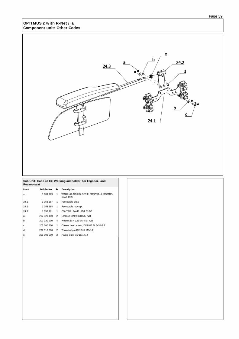
Sub Unit: Code 4616; Walking aid holder, for Ergopor- and Recaro-seat
Item Article-No: Pc Description
– 8 109 729 1 WALKING AID HOLDER F. ERGPOR- A. RECARO-SEAT T928
24.1 1 058 687 1 Receptacle plate
24.2 1 058 688 1 Receptacle tube cpl.
24.3 1 058 161 1 CONTROL PANEL ADJ. TUBE
a 207 320 100 2 Locknut,DIN 980/8,M6, A3T
b 207 330 200 4 Washer,DIN 125-B6,4 St. A3T
c 207 300 800 2 Cheese head screw, DIN 912 M 6x20-8.8
d 207 510 300 2 Threaded pin DIN 914 M8x16
e 205 006 000 2 Plastic slide, 15/15/1,5-2

Page 40
OPTIMUS 2 with R-Net / a Component unit: Other Codes
Sub Unit: Code 993; Baggage box
Item Article-No: Pc Description
– 1 072 612 1 Baggage box with bracket Code 993
24.1 205 660 000 1 Baggage box, black for Co 993 W=385mm D=389mm H=308mm V=26 l
24.2 1 058 698 1 Locking bolt "(L=422.3MM
24.3 206 323 200 2 Compression spring LC-042F-11 MW
24.4 206 555 600 1 Thrust bearing, Form S
24.5 1 058 699 1 Baggage box bracket cpl.
24.6 1 072 611 1 Guide
24.7 1 058 695 1 Counter bracket
24.8 1 058 703 1 Baggage box angle cpl.
24.9 1 058 697 1 Locking angle
24.10 206 556 200 2 Friction bearing form F IGLIDUR G
24.11 207 412 100 1 Hex. cap nut M 8 8 A3T
24.12 205 001 400 1 Spherical button DIN 319,d=25 M6
a 207 380 000 3 Filister head screw M6x20 DIN7380 10,9 A3T
b 207 303 400 4 Cheese head screw DIN 912 M 8x20-8.8
c 207 330 300 5 Washer DIN 125 - B8,4 ST A3T
d 207 320 200 4 Locknut DIN 985 M8-8 A3T
e 207 330 200 3 Washer,DIN 125-B6,4 St. A3T
f 207 320 100 3 Locknut,DIN 980/8,M6, A3T
g 207 310 400 1 Hexagon screw
h 207 341 000 1 Filister head screw
j 207 335 000 1 Washer DIN 9021, B 8.4
k 207 302 200 2 Cheese head screw DIN 912 M6x40
Sub Unit: Code 994, Baggage rack
Item Article-No: Pc Description
24 1 072 483 1 Baggage rack asmb. Code 994

Page 41
OPTIMUS 2 with R-Net / a Component unit: Other Codes
Sub Unit: Code 4779; Splash guard for drive wheel
Item Article-No: Pc Description
Code 816; Splash guard for steering wheels
– 1 062 500 1 Rear splash guard Code 816 1 pair
24 1 062 499 2 Rear splash guard asmb (1 piece)
24.4 1 062 498 1 Rear splash guard
24.3 1 062 496 1 Splash guard bracket
b 205 571 900 3 POP blind rivet D=4.8x10.3 black
Code 4779; Splash guard for drive wheel
– 1 063 885 1 Splash guard front (1 pair) for drive wheels Code 4779
24.1 1 062 503 1 Front splash guard right
24.1a 1 062 502 1 Front splash guard left
24.2 1 063 886 2 Distancer sleeve
a 205 596 400 4 Flat head screw M 6x20-4.8
e 207 382 500 4 FIL. HEAD SCREW HEX SOCK+FLAT M 6 X 12 10.9 LUG TUF-LO
c 207 335 100 6 Washer DIN 9021-B6,4 ST A3T
Sub Unit: Code 4941; Flex bracket
Item Article-No: Pc Description
24.2 1 072 604 1 Receptacle tube for Code 24 (operating module or mirror)
24.3 205 113 800 1 Wing screw M8x15
24.4 1 064 395 1 Profile tube
24.5 1 064 394 3 Clamping plate w thread
24.6 1 064 387 1 Hinge rod
24.7 1 064 390 1 Telescopic tube
24.8 205 112 200 3 KIPP clamping lever, M6 x 20 black
24.9 1 064 393 3 Clamping plate w hole
24.10 1 064 388 1 Ball pin w hole
24.11 1 064 391 1 Telescopic rod
b 207 302 000 3 Cheese head screw DIN 912 M6x60
c 205 006 000 2 Plastic slide, 15/15/1,5-2
d 207 172 000 1 threaded pin M 4 X 5 45H A2R 8007500
– 207 907 900 1 Groove pin 3 x 12 DIN1475
– 1 064 389 1 Ball pin w inner thread
– 1 064 386 2 Ball pin w outer thread
Code 4941-24; Flex bracket-side bar, foldaway
– 1 072 629 1 FLEX2 Bracket asmb. Code 24-4941
->Bei Code 24 Seitenteilen
Code 4941; Flex bracket
– 1 066 600 1 FLEX2 Bracket asmb. Code 106-4941
->Bei Code 106 Seitenteilen

Page 42
OPTIMUS 2 with R-Net / a Component unit: Revetment
Sub Unit: Revetment
Item Article-No: Pc Description
24.1 1 070 911 1 Front revetment (Gearbox revetment)
a 207 301 700 4 Cheese head screw,DIN 912, M 6x16-8.8
– 207 335 100 4 Washer DIN 9021-B6,4 ST A3T
– 207 320 100 4 Locknut,DIN 980/8,M6, A3T
24.2.1 5 006 536 2 Turn signal asmb -1 pair w 12V bulbs (w/o stud bolt)
– 206 964 210 2 Ball lamp 12V 21W base BAY9S (for revetm turn signal)
– 8 406 587 2 FILAMENT BULB 12 V 10 W
24.2.2 206 963 100 2 HEADLIGHT
– 206 605 900 1 O-ring 40 x 7
– 1 071 624 2 Lighting cable asmb. (for side revetment)
24.3 1 057 756 1 ELECTRONIC COVER
24.4 1 057 755 1 BATTERY COVER TOURING 928
24.5 1 063 941 1 Rear revetment asmb Code 183 Silver-metallic
24.5.1 206 963 300 1 Z-REFLECTOR RED
24.5.2 1 057 809 2 TAILLIGHT ASMB.
– 1 057 808 2 TAILLIGHT CABLE ASMB.
24.5.3 206 962 200 2 REFLECTOR RED D=60
24.6 205 111 300 1 Handwheel D=40, black DIN 934- A2 with nut M6
Sub Unit: Revetment
Item Article-No: Pc Description
b 205 692 600 4 PAN HEAD SCREW M6 X 12 TYPE KF 4.8
c 205 596 400 2 Flat head screw M 6x20-4.8
d 205 596 800 2 Flat head screw
e 205 693 300 4 SHEET METAL NUT M6
f 207 335 100 4 Washer DIN 9021-B6,4 ST A3T
– 205 596 900 2 Plastic decorative cap
Code 183; Colour: metallic silver
24.2 1 072 409 1 Side revetment right asmb Code 183 - silver metallic
24.2a 1 072 408 1 Side revetment left asmb Code 183 - silver metallic
Code 134; Colour: Ocean blue
24.2 1 072 406 1 Side revetment left asmb Code 134 - Ocean blue
24.2a 1 072 407 1 Side revetment right asmb Code 134 - Ocean blue

Page 43
OPTIMUS 2 with R-Net / a Component unit: Accessories
Sub Unit: Accessories
Item Article-No: Pc Description
Code 539; Amplified horn
– 1 072 417 1 Stronger horn Code 539
Code 803; Seatbelt (extra long)
– 1 072 494 1 Retaining strap Code 803 Extra long with buckle
Code 814; Horizontal pushing rod
– 8 108 609 1 Pushing bar cpl for Recaro and external seat systems
– 1 058 968 1 Pushing bar asmb Code 814-961 (ERGOSTAR seat)
Code 822; Shoe fastening strap
– 1 054 378 1 Shoe fastening strap Code 822 1 pair
Code 823; Heel support
– 1 012 396 1 Heel retainer Code 823
Code 833; Safety belt
– 1 070 819 1 Retaining strap Code 833 with buckle
Code 924; Plastic cover
– 205 537 700 1 Shrouding cover, Code 924 Mod.420 (120cm x 70cm x 105cm)
Code 936; Sliding board
– 205 029 500 1 Slip board, Code 936
Code 951; Accessory net
– 205 538 400 1 Hospital chair net Code 951

Your specialist dealer
We move people.
MEYRA-ORTOPEDIA Vertriebsgesellschaft mbH Meyra-Ring 2 • D-32689 Kalletal-Kalldorf P.O. Box 1703 • D-32591 Vlotho Fon +49(0)5733 922-333 Fax +49(0)5733 922-9333 [email protected] • www.meyra.de [email protected] • www.ortopedia.de
VIS III / Order-No.: 205 340 401 Status date: 2011-03 Subject to technical modifications