space&environmentimpacts&on& geostaonary&communicaons...
TRANSCRIPT
Space Environment Impacts on Geosta2onary Communica2ons
Satellites Thesis Proposal Defense
Whitney Q. Lohmeyer
Commi@ee Chair: Kerri Cahoy May 6, 2013
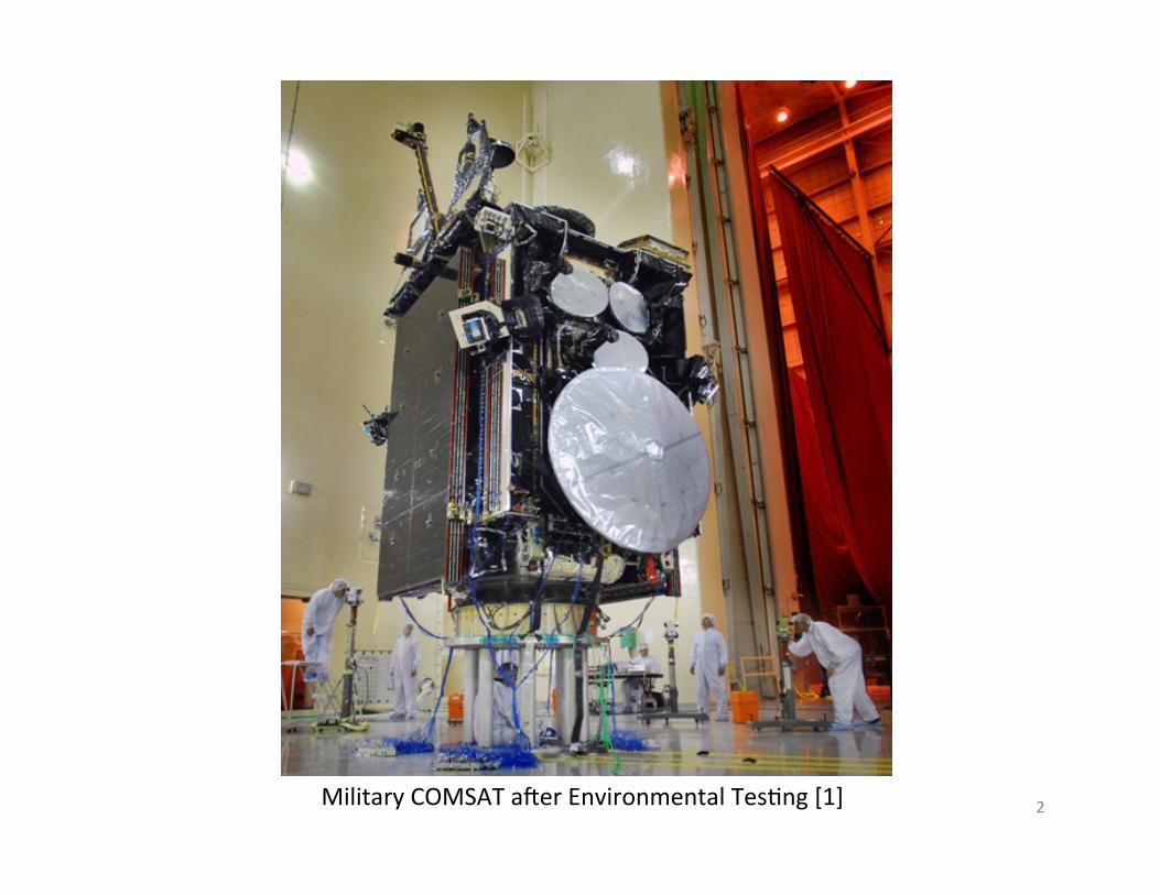
2 Military COMSAT aLer Environmental Tes2ng [1]

Outline
• Problem Statement • Objec2ves • Research Ques2ons
– Trends in Geosta2onary Communica2on Satellite (GEO COMSAT) Design
– Study of Known Component Amplifiers and Solar Array Degrada2on
– Anomalous Component Detec2on Algorithm • Plan for Progression
3
Free Space Path Loss

Problem Statement • In 2008, the NRC hosted a workshop – Societal & Economical Impacts of Space Weather [2] – >250 communica2ons satellites (COMSATs) – $75 billion investment and $25 billion revenue
• SW is a constant, on-‐going problem – At GEO, SW drives design redundancy
• To quan2fy how space weather effects COMSAT performance – Must have both space weather (SW) data and satellite telemetry
– Obtaining satellite telemetry is difficult!
4
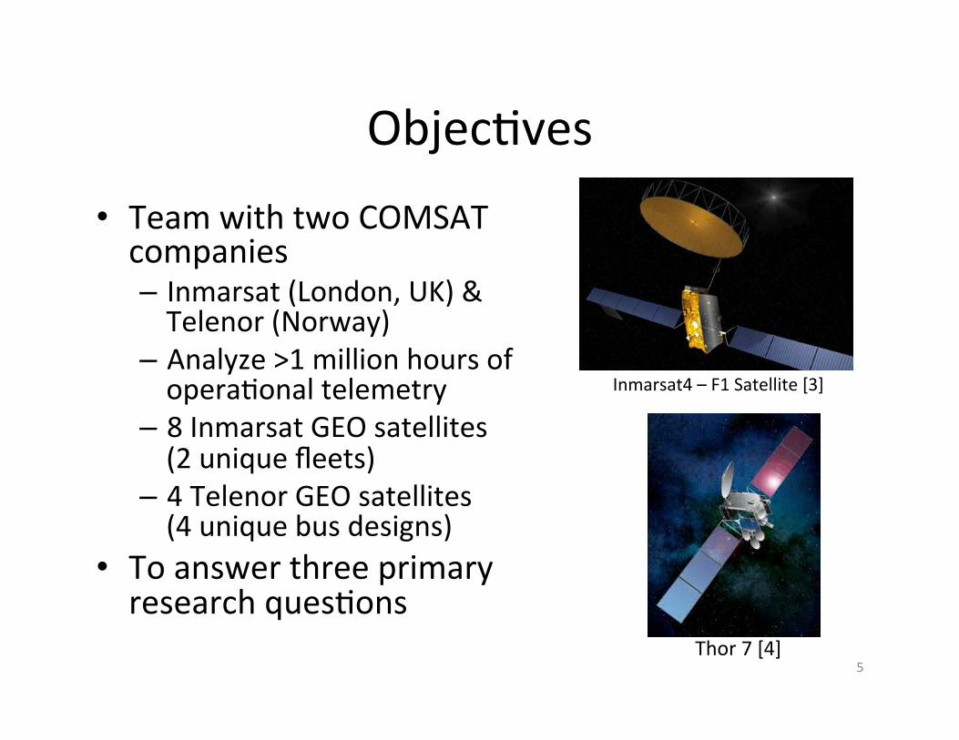
Objec2ves • Team with two COMSAT companies – Inmarsat (London, UK) & Telenor (Norway)
– Analyze >1 million hours of opera2onal telemetry
– 8 Inmarsat GEO satellites (2 unique fleets)
– 4 Telenor GEO satellites (4 unique bus designs)
• To answer three primary research ques2ons
Inmarsat4 – F1 Satellite [3]
Thor 7 [4] 5
Research Ques2ons
1. What are the future planned capabili2es and design trends for GEO COMSAT -‐ How are satellite components, specifically power
amplifiers evolving with these trends? 2. How does SW affect current GEO COMSAT
components -‐ In terms of low-‐energy electrons, the Kp index, high-‐
energy protons and electrons, and galac2c cosmic rays 3. Can we use GEO COMSAT telemetry to understand
more about SW phenomena in general and not just at the 2me of the anomaly? -‐ Analy2cal tools (sta2s2cs, FT -‐ traffic analysis, deriva2ves)
6

Outline
• Problem Statement • Objec2ves • Research Ques2ons
– Trends in Geosta2onary Communica2on Satellite (GEO COMSAT) Design
– Study of Known Component Amplifiers and Solar Array Degrada2on
– Anomalous Component Detec2on Algorithm • Plan for Progression
7
Outline
• Problem Statement • Objec2ves • Research Ques2ons
– Trends in Geosta-onary Communica-on Satellite (GEO COMSAT) Design
– Study of Known Component Amplifiers and Solar Array Degrada2on
– Anomalous Component Detec2on Algorithm • Plan for Progression
8

1. Trends in GEO COMSATs
• COMSATs represent the most important applica2on of commercial satellites today – Capabili2es are growing to accommodate high demands of informa2on distribu2on [5]
– Higher data rates, higher band width, smaller components, increased power and efficiency, etc.
• Amplifiers consume ~85% of satellite power [6,7] – Control satellite performance – Amplifiers are the component of focus for the trend analysis
9
1960 – Echo 1 [18]
2013 – Inmarsat I5 [19]

What are power amplifiers? • Key components in satellite comm systems
– Strengthen uplink signals that are weakened from free space path loss [6,8,9]
– Amplifier units consume ~85% of the spacecraL bus power [6,7]
Free Space Path Loss
• Two primary types: solid state power amplifiers (SSPAs) and traveling wave tube amplifiers (TWTAs)
• Technologies experienced rapid change over past decades
10
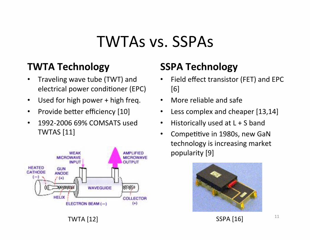
TWTAs vs. SSPAs TWTA Technology • Traveling wave tube (TWT) and
electrical power condi2oner (EPC) • Used for high power + high freq. • Provide be@er efficiency [10] • 1992-‐2006 69% COMSATS used
TWTAS [11]
SSPA Technology • Field effect transistor (FET) and EPC
[6] • More reliable and safe • Less complex and cheaper [13,14] • Historically used at L + S band • Compe22ve in 1980s, new GaN
technology is increasing market popularity [9]
SSPA [16] TWTA [12] 11

Historic SSPA vs. TWTA Studies [6,16] 1991 -‐ European Space
and Technology Center (ESTEC)
1993 – NASA Lewis
2005 – Boeing
75 satellites / 11 operators >463 years of satellite
opera2on
72 satellites >497 years of satellite
opera2on
>100 satellites >12600 years of amplifier
opera2on
TWTAs (1765 C-‐ and Ku-‐band) and SSPAs (309 C-‐band)
TWTAs (855 C-‐ and Ku-‐band) and 365 (C-‐band)
TWTAs (1783 Ku-‐band) SSPAs (944 C-‐band)
TWTAs more reliable (790 FITS SSPA and 680 FITS TWTA)
TWTAs 1/3 more reliable than SSPAs
FITS on TWTAS less than SSPAs – No reliability diff.
6/5 TWTA redundancy 3/2 SSPA Redundancy
Failure rates increased by 8% at Ku-‐band
Explored failure mechanisms – 9 % satellites
had 2 SSPA failures
Similar RF output levels SSPAs use for 20-‐40 W, TWTA used for 50-‐70 W
SSPAs 66W less RF output than TWTAs
12

TWTA vs. SSPA Study – Our Extension
What are the future planned capabili2es and design trends for GEO COMSAT?
-‐ How are satellite components, specifically power amplifiers evolving with these trends?
Approach: • Analyze >150 years (>1 million hours) of amplifier data
– >450 SSPAs (Inmarsat) and ~100 TWTAS (Telenor) • Define the current amplifier capabili2es
– Compare technologies – Reliability (number of failures) – Failure mechanisms (SW related?) – Hardware characteris2cs – size, mass, cost (if possible)
13

Outline
• Problem Statement • Objec2ves • Research Ques2ons
– Trends in Geosta2onary Communica2on Satellite (GEO COMSAT) Design
– Study of Known Component Amplifiers and Solar Array Degrada2on
– Anomalous Component Detec2on Algorithm • Plan for Progression
14

Outline
• Problem Statement • Objec2ves • Research Ques2ons
– Trends in Geosta2onary Communica2on Satellite (GEO COMSAT) Design
– Study of Known Component Amplifiers and Solar Array Degrada-on
– Anomalous Component Detec2on Algorithm • Plan for Progression
15
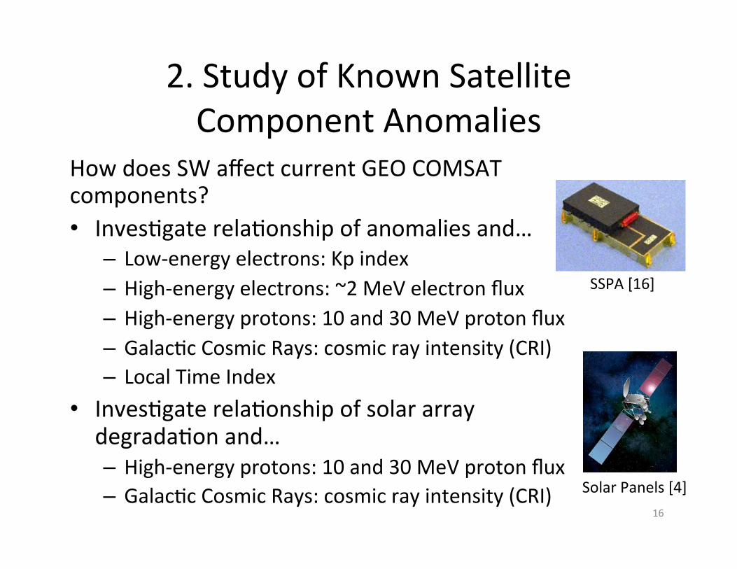
2. Study of Known Satellite Component Anomalies
How does SW affect current GEO COMSAT components? • Inves2gate rela2onship of anomalies and…
– Low-‐energy electrons: Kp index – High-‐energy electrons: ~2 MeV electron flux – High-‐energy protons: 10 and 30 MeV proton flux – Galac2c Cosmic Rays: cosmic ray intensity (CRI) – Local Time Index
• Inves2gate rela2onship of solar array degrada2on and… – High-‐energy protons: 10 and 30 MeV proton flux – Galac2c Cosmic Rays: cosmic ray intensity (CRI)
16
SSPA [16]
Solar Panels [4]

Acquiring Data – Space Weather Data and Communica2ons Satellite Data
Geostationary Operational Environment Satellite [8]
(GOES)
2 MeV Electron Flux
30 MeV Proton
Flux
OMNI2 Database
Kp Index
Sunspot Number
Magnetic Field Components
(Bz)
Solar Wind Speed
10 and 30 MeV
Proton Flux
Los Alamos National Labs (LANL) Data
1.8-3.5 MeV Electron Flux
Inmarsat
SSPA Current
SSPA Temp
Solar Array Current and
Voltage
Total Bus Power
Single Event Upsets
Anomaly Log
Telenor
TWTA Current
TWTA Temp
Solar Array Power
Anomaly Log
17

Current Findings – SW Effects on Inmarsat Anomalies
Twenty-‐six SSPA anomalies between 1996-‐2012 • Fleet A anomalies occur in
declining phase of solar cycle – Enhanced electron flux
• 11/26 anomalies occur 1-‐2 weeks aLer enhanced electron flux
• No obvious rela2onship with Kp, proton flux, or local 2me
The Space Environment [16]
18

Fleet A SSPA Anomalies + Solar Cycle
19

SSPA Anomalies and High Energy Electron Flux
20

Local Time of SSPA Anomalies
21
Outline
• Problem Statement • Objec2ves • Research Ques2ons
– Trends in Geosta2onary Communica2on Satellite (GEO COMSAT) Design
– Study of Known Component Amplifiers and Solar Array Degrada2on
– Anomalous Component Detec2on Algorithm • Plan for Progression
22
Outline
• Problem Statement • Objec2ves • Research Ques2ons
– Trends in Geosta2onary Communica2on Satellite (GEO COMSAT) Design
– Study of Known Component Amplifiers and Solar Array Degrada2on
– Anomalous Component Detec-on Algorithm • Plan for Progression
23
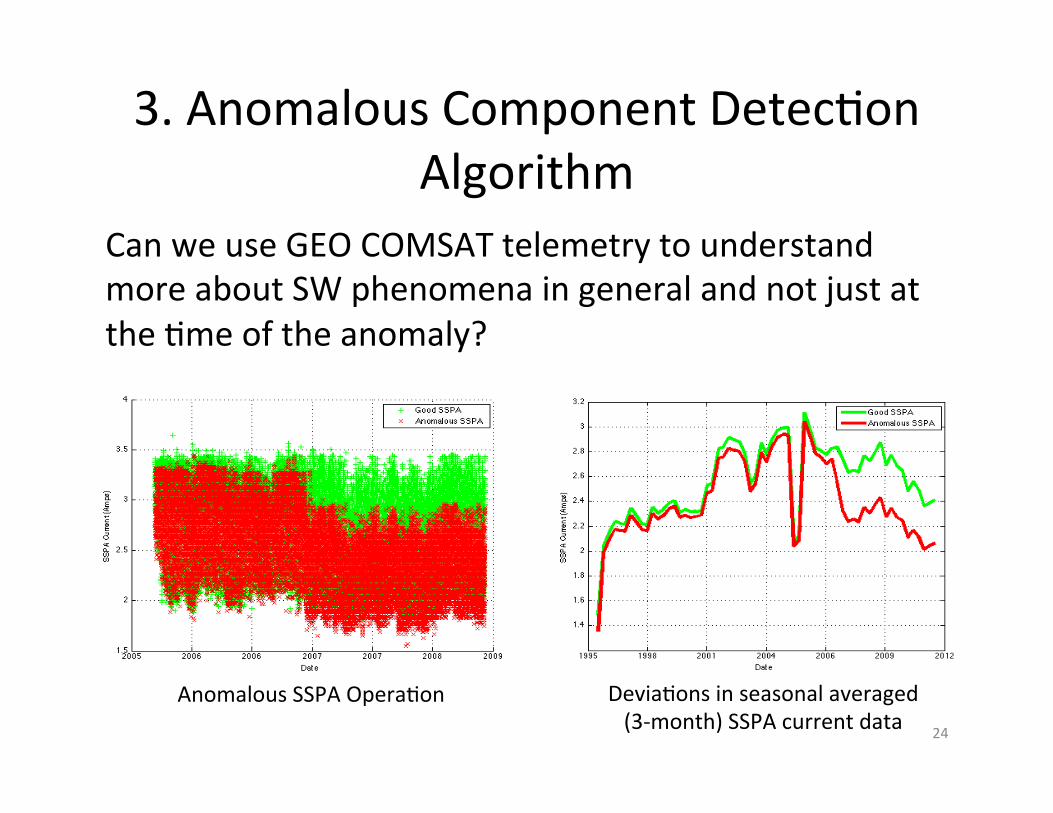
3. Anomalous Component Detec2on Algorithm
Can we use GEO COMSAT telemetry to understand more about SW phenomena in general and not just at the 2me of the anomaly?
Devia2ons in seasonal averaged (3-‐month) SSPA current data
Anomalous SSPA Opera2on 24

3. Anomalous Component Detec2on Algorithm
Import temporal telemetry data – each parameter (SSPA current, solar array voltage, etc.) and 2me stamp Incorporate analy2cal tools
– Periodic Analysis: Fourier transform – Differen2al Analysis: Deriva2ve (understand when telemetry changes slope)
– Pa@ern Matching: compare structure of telemetry over specified periods
– Sta2s2cal Analysis: running averages, standard devia2ons, etc.
25
Traffic Analysis
Outline
• Problem Statement • Objec2ves • Research Ques2ons
– Trends in Geosta2onary Communica2on Satellite (GEO COMSAT) Design
– Study of Known Component Amplifiers and Solar Array Degrada2on
– Anomalous Component Detec2on Algorithm • Plan for Progression
26

Major Goals and Upcoming Milestones
• May 2013: Present SW analysis at SPENVIS Conference • June 2013: Present lecture on Geomagne2c Storms – GEM Workshop 2013
• June 2013: A@end Space Weather Enterprise Forum • April 2013: Publish Inmarsat results in AGU Space Weather Journal: submi8ed
• August 2013: Finish gathering telemetry for study – Ac2vely engaged with two (poten2ally three) other operators
• Feb. 2013 – May 2015: Conduct analysis/write disserta2on
• May 2015: Defend thesis
27
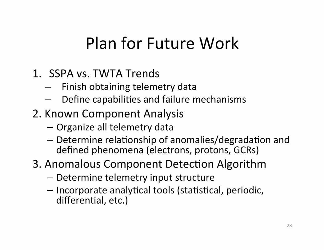
Plan for Future Work 1. SSPA vs. TWTA Trends
– Finish obtaining telemetry data – Define capabili2es and failure mechanisms
2. Known Component Analysis – Organize all telemetry data – Determine rela2onship of anomalies/degrada2on and defined phenomena (electrons, protons, GCRs)
3. Anomalous Component Detec2on Algorithm – Determine telemetry input structure – Incorporate analy2cal tools (sta2s2cal, periodic, differen2al, etc.)
28

References [1] Military COMSAT image -‐ h@p://www.spacemankind.com/pr/2009/09/16/s5-‐second-‐aehf-‐comm-‐sat-‐completes-‐major-‐environmental-‐test-‐at-‐lockheed.aspx [2] “Severe Space Weather Events – Understanding Societal and Economic Impacts Workshop” Na9onal Research Council. Na2onal Academy of Sciences. <h@p://www.nap.edu/catalog/12507.html>. [3] Inmarsat 4 Picture – h@p://space.skyrocket.de/doc_sdat/inmarsat-‐4.html [4] Thor7 Imageh@p://www.ssloral.com/html/pressreleases/pr20110620.html [5] Aloisio et al. (2010), “R&D Challenges for Broadband Satcomms in 2020”, 1EEE Interna2onal Vacuum Electronics Conference, 18-‐20 May 2010. [6] Strauss, R. (1993), Orbital Performance of Communica2on Satellite Microwave Power Amplifiers (MPAs), Interna9onal Journal of Satellite Communica9ons, 11, 279-‐285. [7] Illoken, E. (1987), TWT Reliability in Space, Aerospace and Electronic Systems Magazine, IEEE, 2(7), 22-‐24. [8] Robbins et al. (2005), Performance and reliability advances in TWTA high power amplifiers for communica2ons satellites. In Military Communica9ons Conference, 2005. MilCOM 2005, 1887-‐1890. [9] Kaliski, M. (2009), “Evalu2on of the Net Steps in Satellite High Power Amplifier Technology: Flexible TWTAs and GaN SSPAs”, IEEE Interna2onal Vacuum Electronics Conference, 28-‐30 April 2009.
29

References [10] Komm et al., (2001), “Advances in Space TWT Efficiencies”, IEEE Transac9ons on Electron Devices, 48(1). [11] Mallon, K.P. (2008), “PL.6: TWTAs for Satellite Communica2ons: Past, Present and Future”, IEEE, 14-‐15 [12] TWTA Image www2.jpl.nasa.gov [13] Escalera, N., (2008), Ka-‐band, 30 wa@s solid state power amplifier. In Microwave Symposium Digest. 2000 IEEE MTT-‐S Interna9onal (Vol. 1, pp. 561-‐563), IEEE. [14] Sechi, F., and M. Buja{ (2009), Solid-‐State Microwave High-‐power Amplifiers. Artech House, M.A. [15] SSPA Image h@p://www.astrium.eads.net/en/equipment/l-‐band-‐sspa.html. [16] Strauss, R. (1994), Reliability of SSPA’s and TWTA’s, IEEE Transac9ons on Electron Devices, 41(4), 625-‐626. [17] Space Environment Image sohowww.nascom.nasa.gov/spaceweather/. [18] Echo 1 image – h@p://www.space.com/8973-‐1st -‐communica2on -‐satellite-‐giant-‐space-‐balloon-‐50-‐years.htm [19] Inmarsat 5 image – space.skyrocket.de [20] Electromagne2c Energy Spectrum Image – donsnotes.com/tech/em-‐spectrum.html
30

Back-‐Up Slides
31

32

SSPA vs. TWTA Historical Trends [6,11]
33
TWTA Technology • First successful RF amplifier for
COMSATS – 1960 • From 1970-‐1985, RF output
capability increased 1000% for 4 (S), 12 (X), and 20 (K) GHz
• 1990 – TWTAs were capable of ~50% efficiency, Ku band – 50 W
• 2005 – TWTAs opera2ng across L-‐Ka band with 15-‐150 W RF output, some specified for up to 250W at 60% efficiency
• 2012 – L-‐band 65%, 140W (3x efficiency of SSPA at 2me)
SSPA Technology • SSPAs introduced in 1970s for
space applica2ons – compe22ve in 1980s (amplifier of choice)
• 1990s – SSPAs were capable of ~35% efficiency, used for 20-‐40W despite low efficiencies
• 2000 – SSPAs opera2ng in low frequency bands (L, S, and C) with output RF of 30 W, highest Ka-‐band SSPA 30 W with 20% efficiency

Previous Contribu2ons
• April 2012: Space Weather Workshop – presented ini2al Inmarsat work
• September 2012: AIAA Interna2onal Communica2ons Satellite Systems Conference (ICSSC) – presented Inmarsat analysis
• March 2013: IEEE Aerospace – presented Inmarsat SEU and SEP Analysis
34