space shuttle main engine structural analysis … · preburner pimp housing stress analysis report...
TRANSCRIPT

LMSC-HEC TR F268584-lllA
FINAL REPORT
SPACE SHUTTLE MAIN ENGINE STRUCTURAL ANALYSIS AND DATA REDUCTIONEVALUATION
VOLUME
I
5
3A: HIGH PRESSURE OXIDIZER TURBO-PUMP PREBURNER PUMP HOUSING STRESS ANALYSIS REPORT
April 1989
Contract NAS8-37282
id
Po NATIONAL AERONAUTICS AND SPACE ADMINISTRATION GEORGE C. MARSHALL SPACE FLIGHT CENTER, AL 35812
a 03 u) I
h) 4 ch rb c
by
Robert V. Shannon, Jr.
Huntsville Engineering Center 4800 Bradford Blvd., Huntsville, AL 35807
https://ntrs.nasa.gov/search.jsp?R=19890018323 2018-05-29T09:54:35+00:00Z

1 I I I I I I I I 8 I I I I I 1 I I I
LMSC-HEC TR F268584-IIIA
FINAL REPORT
SPACE SHUTTLE W I N ENGINE STRUCTUIW ANALYSIS MID DATA REDUCTIOI/EVALUATIOI
VOLUME 3A: HIGH PRESSURE OXIDIZER TURBO-PW PREBURNER PIMP HOUSING STRESS ANALYSIS REPORT
April 1989'
Contract PAS8-37282
Prepared €or
UATIONAL AEROUAUTICS AM) SPACE ADHIUISTRATION GEORGE C. MARSHALL SPACE FLIGHT CENTER, AL 35812
by
Robert V . Shannon, Jr.
LOCKHEED-HUNTSVILLE ENGIUEERIBIG CENTER 4800 Bradford Boulevard
Huntsville, AL 35807

LMSC-HEC TR F268584-IIIA
Appendix A IBM AND CRAY RUNSTREAHS
LOCKHEED-HUNTSVILLE ENGINEERING CENTER

LMSC-HEC TR F268584-IIIA
APPENDIX A
IBM RUNSTREAM
EDIT ---- CRVS202.HPOTP.GEN(IBMJCL)
000001 //CRVS202 JOB (6ED554590417),'SHANON,NOTIFY=CRVS202,CLASS=A, 000002 // MSGCLASS=X 000003 //DELETE EXEC PGM=IEFBR14 000004 //F1 DD DISP=(MOD,DELETE).UNIT=SYSDA.
. . . . . . . . . . . . . . . . . . . . . . . . . . . . . TOP OF DATA . . . . . . . . . . . . . . . . . . . . . . . . . . .
000005 / / SPACE=(TRK,(l)),DSN=CRVS202.ANSYS.WOTP.FILE27 000006 / / * 000007 NANSYS43 EXEC ANSYS43,C=CATLG, 000008 / / F27='CRVS202.ANSYS.HPOTP.FILE27' 000009 //GO.FLLE27 DD SPACE=(4652,(9000,500),RLSE), 0000 10 / / DISP=(NEW,CATLG),UNIT=(SYSDA,8) 0000 1 1 //*O.FILE28 DD DSN=CRVS202.ANSYS.HPOTP.FILE28, 0000 12 / / * 0000 13 //GO.FM)5FO01 DD DSN=CRVS202.HPOTP.GEN(HPOTP7), 0000 14 / / SPACE=(4096,(9000,1500),RLSE),DISP=SHR 000015 / /
DCB=(RECFM=FB,LRECL=80,BLKSIZE=400),DISP=(OLD,KEEp)
*************e** ** *******e* BOTTOM OF DATA ******e*** * **** ** ** * ** ** *
CRAY RUNSTREAM
00000 1 JOB ,JN=CRVS202,MFL=6000000,T=6000,0LM=8000,SSD=50000. 000002 ACCOUNT,AC=6ED5545WQl7,US=CRVS202. 000003 OEIION,STAT. 000004 FETCH,DN=E.T27,TEXT='DSN=CRVS202.ANSYS.HFQTP.FILE27'. 00 00 05 ACCESS ,DN=ANSYS ,F'DN=SOL43N,ID=ANSYS43 ,OWN=SYSTEM.
00 00 0 7 ACCESS ,DN=AUTH43 ,II)=ANS YS43 ,OWN=SYSTEM. ACCESS AUTHORIZATION FILE 000008 MODE,BT=DISABLE. 000009 ANSYS. 0000 10 SAVE,DN=FT14,PDN=HPOTl4. 0000 1 1 DISPOSE,DN=FT14,DC=ST,TEXT='DSN=CRVS202.ANSYS.HPOTP.FILE 14? 0000 12 'DISP=( .CA"LG),'" 0000 13 'SPACE=(CYL,( 120,20),RLSE) ,IA
0000 14 'DCB=(RECFM=FB,BLKSIZE=6320,LRECL=80)',WAIT. 000015 /EOF 000016 /CORE,5.7E6 0000 17 /INPUT,27 0000 18 FINISH 000019 /AUXl 000020 BCDCNv 00002 1 FINISH
000006 ASSIGN,DN=FI'l 1 ,LM=400000,BS=24,DV=SSD-0-20.
. . . . . . . . . . . . . . . . . . . . . . . . . . . BOTTOM OF DATA . . . . . . . . . . . . . . . . . . . . . . . . .
LOCKHEED-HUNTSVILLE ENGINEERING CENTER
0913R
LMSC-HEC TR F268584--IIIA
FOREWORD
This volume of the final report summarizes the model generation and structural analysis performed for the high
pressure oxidizer turbo-pump (HPOTP) preburner pump volute housing located on the main pump end of the HPOTP in the Space Shuttle Main Engine. An ANSYS finite element model of the volute housing was built and executed by Robert V. Shannon, Jr., and Hark D. Stansberry of the Structures & Mechanics Group at the Lockheed-Huntsville Engineering Center under NASA Contract NAS8--37282. A static structural analysis was performed on the Marshall Space Flight Center (HSFC) Engineering Analysis and Data System (EADS) Cray-XMP supercomputer.
ii
LOCKHE I? D- HUNTSV I LLE ENGINE KRING C ENT E R

LHSC-HEC TR F268584-IIIA
CONTENTS
Page
ii
1
3
7
9
10
12
13
15
Sect ion
FOREWORD
INTRODUCTION AND OVERVIEW
MODEL DESCRIPTION
BOUNDARY CONDITIONS AND EXTERNAL LOADS
MATERIAL PROPERTIES
STRUCTURAL ANALYSIS/RESULTS
S W R Y
RECO~ENDATIONS
REFERENCES
Appendix
A IBM and Cray Runstreams A-1
LIST OF TABLES
Table
1
2
3
4
5
6
Element Material and Type Numbers for Global Element Reg ions 16 Element Material and Type Numbers for Elements Not in the Tongue Region 16 Element Material and Type Numbers for Elements in the Tongue Region 16 Node Angle Locations for Nodes from -25" to 147", except on Discharge Pipe 17 Node Angle Locations f o r Nodes from 150" to -30", except on Discharge Pipe 18 Numbering Scheme for Nodes from -21" to 147", Except
19 for Web and Flange Nodes
iii
LOCKHEED-HUNTSVILLE ENGINEERING CENTER ~~ ~~
~~ ~~

LIST OF TABLES (Concluded)
Table
~~ ~~~~
LMSC-HEC TR F268584-IIIA
7 Numbering Scheme for Nodes from 150" to -75". except
8 Maximum Housing Von Mises Stresses 9 Maximum Housing Principal Stresses
€or Web and Flange Nodes
Page
20 21 21
LIST OF FIGURES
Figure Page
6 7 8 9 10 11 12 13 14 15
16
17
18 19
20 21 22 23 24 25 26 27
Schematic of the HPOTP Major Components 22 Preburner Pump Housing and Preburner Pump Components 23 Preburner Pump Housing, View from Inlet Side 24 Cutaway View of Preburner Pump Housing 25 Orientation of Discharge Pipe with respect to Pump Housing Volute Passage 26 Overall Dimensions of the Preburner Pump Housing 27 Cross-Section Regions of the Model 28 Preburner Pump Housing Model Plot, View A from Inlet Side 29 Preburner Pump Housing Model Plot, View B from Inlet Side 30 Preburner Pump Housing Model, View from Main Pump Side 31 Cutaway View of Preburner Pump Housing Model 32 Diffuser Vane Elements 33 Two Preburner Pump Model Cross Sections 180" Apart 34 Pressure Loads and Boundary Conditions 35 INCONEL 718 Young's Modulus as a Function of Absolute Temperature (Rankine) 36 INCONEL 718 Poisson's Ratio as a Function of Absolute Temperature ( Rankine 1 36 Vanes Viewed from Inlet Side, Sigma -1 (Maximum Principal Stress 37
Vanes Viewed from Inlet Side, Sigma -E (Von Mises Equivalent Stress 39 Vanes Viewed from Pump Side, Sigma -1 40 Vanes Viewed from Pump Side, Sigma -Z 41 Vanes Viewed from Pump Side, Sigma -E 42
Vanes Viewed from Inlet Side, Sigma -Z (Axial Stress) 3a
Sigma -1 for 68" to 76" Section 43 Sigma -E for 68" to 76" Section 44 Sigma -1 for 14" to 22" Section 45
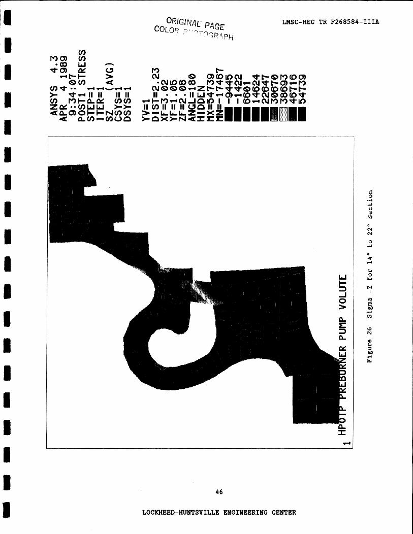
Sigma -E for 14" to 22" Section 47 Sigma -Z for 14" to 22" Section 46
iv
LOCKHEED-HUNTSVILLE ENGINEERING CENTER
LMSC-HEC TR F268584-IIIA
1. INTRODUCTION AND OVERVIEW
The high-pressure oxid izer turbo-pump (HPOTP) conta ins two s ingle-s tage
cen t r i fuga l pumps on a common s h a f t which is dr iven d i r e c t l y by a two-stage
hot-gas turb ine . A schematic of t he HPOTP major components can be seen i n Figure 1. The HPOTP has o v e r a l l dimensions of 24 by 36 i n . and an approximate
o v e r a l l weight of 575 l b .
There a r e three main i n l e t s and th ree main o u t l e t s i n the HPOTP. The
i n l e t s are the main pump i n l e t , the preburner pump i n l e t , and the turb ine
i.nlet. The main f l u i d o u t l e t s a r e t h e main pump discharge, preburner pump
discharge, and t h e turb ine discharge. Liquid oxygen e n t e r s t h e main pump
i n l e t from t h e low pressure oxid izer turbo-pump (LPOTP) and the main pump
discharge suppl ies this oxygen t o the LPOTP turb ine , t h e heat exchanger, the
preburner pump ( v i a the preburner pump i n l e t duc t , which is f lange mounted t o
t h e preburner pump i n l e t ) , and the t h r u s t chamber i n j e c t o r .
The preburner pump has a s i n g l e entry impel ler w i t h four f u l l blades and
four p a r t i a l blades.
region of the HPOTP. This figure shows how the preburner pump housing is
f tange mounted t o the main pump housing.
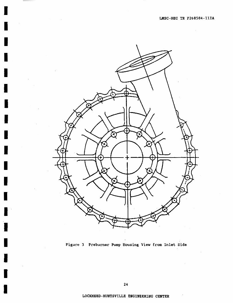
housing from t h e i n l e t s i d e . The preburner pump discharge is evident i n t h i s
f i gu re . The impel ler discharges oxid izer through the pump housing d i f f u s e r
vanes and i n t o the housing volu te passage. The d i f f u s e r vanes cause a f u r t h e r
rise i n ox id ize r pressure. Figure 4 is a cutaway view of the pump housing,
exposing the volu te passage and d i f f u s e r vanes. From t h e volu te passage the
oxid izer passes i n t o the housing discharge p ipe , where i t then leaves the pre-
burner pump housing. Figure 5 presents the o r i e n t a t i o n of t h e discharge p ipe
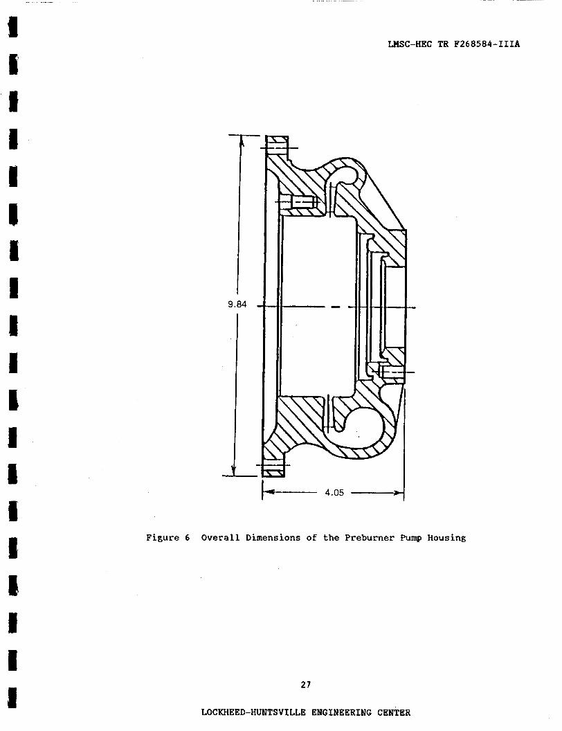
with respec t t o the preburner pump housing volute passage. Figure 6 shows a
cross s e c t i o n of the preburner pump housing and provides t h i s component's
Figure 2 provides a c l o s e r view of t h e preburner pump
Figure 3 gives a view of the pump
I
LOCKHEED-HUNTSVILLE ENGINEERING CENTER

E 'I 4 i I 4 1E I 1 c 5 I 1 4 E 1 E 8 I
overall dimensions. It is important t o note that the preburner pump housing
is a casting and, as such* contains no welds and is of one-piece construction.
The following sections of this report describe the preburner pump housing finite element model, boundary conditions and external loads, material properties, structural analysis and results, and the summary and recommendations.
2
LOCKHEED-HUNTSVILLE ENGINEERING CENTER

LMSC-HEC TR F268584-IIIA
2. MODEL DESCRIPTION
The global coordinate system used for the generation of this model is
exactly the same as that used for the generation of the preburner pump bearing components. the HPOTP turboshaft with the z-axis pointing towards the preburner pump inlet. The Cartesian x-axis Lies at a station angle of 7 0 . 0 ° , relative to the pre- burner pump housing drawing (Ref. 1). The Cartesian y-axis is thus at a drawing station angle of 160.0". The Location of the global origin along the turboshaft is 0.052 in. toward the main pump from the main pump mating surface of the preburner pump housing flange. This flange is clearly identified in Figure 7 , which presents the various regions of each model cross section. With respect to the dimensions (Figure 61, the smallest nodal z value is 0.052 in. and the z-value of the housing inlet mating surface is 4.102 in.
The origin of this system is at the radial symmetric center of
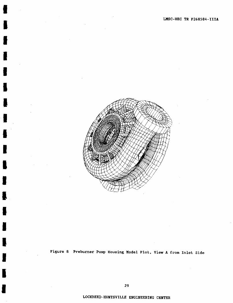
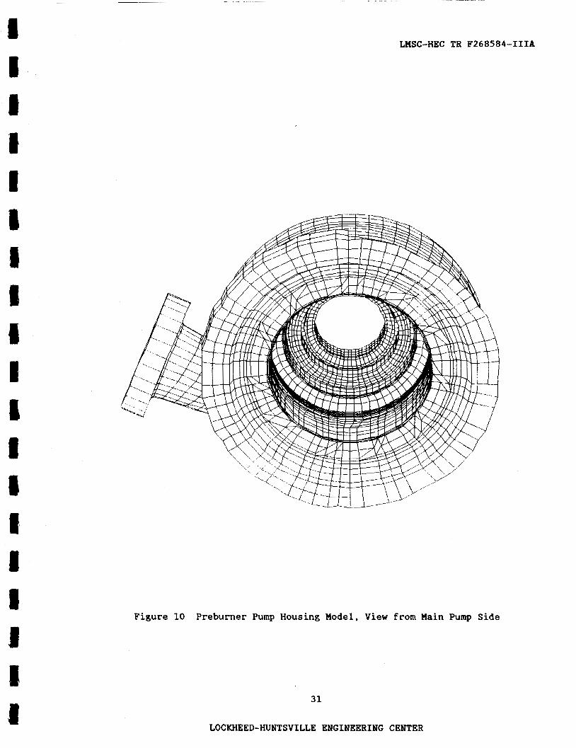
The finite element model of the preburner pump housing contains 15,694 brick and wedge elements, a total of 20,180 nodes, and 59,820 degrees of free- dom. Maximum wavefront for solution of this model is about 2598. The ANSYS limit on model wavefronts is 3000. The plots in Figures 8 and 9 show the model when viewed from the inlet side of the housing. whereas Figure 10 is a view of the model from the main pump side of the preburner pump housing. The support bolt holes were not modeled in this final model due to the complexity caused by the diffuser vane geometry. Figure 11 shows the model when viewed from the inlet side with part of the model cut away to expose part of the vane region. Solid elements modeling the housing diffuser vanes are clearly evident. The stray elements in the foreground are part of the discharge pipe mesh. Finally, Figure 12 is simply a plot of the 11 housing diffuser vanes as they were modeled. Because of the odd number of vanes and the unusual circumferential spacing between them, no modeled vane is exactly like another modeled vane. In addition, all vanes have their noses and tails "clipped" due to overall modeling necessity.
3
LOCKHEED-HUNTSVILLE ENGINEERING CENTER
A ,reakdown o
LMSC-HEC TR F268584-IIIA
the number of elements composing each major region of the model
is given in 'Cables 1 through 3 .
which contains the volute tongue and the discharge pipe between global co- ordinate system angles -75" and -21" (i.e., blueprint station angles between -5" and 49").
Tables 2 and 3 refer to the "tongue region,"
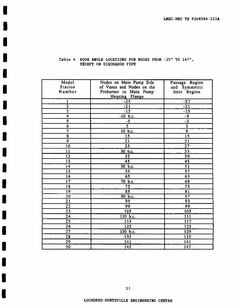
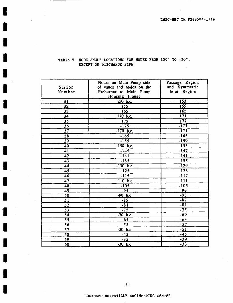
Tables 4 and 5 show the global cylindrical coordinate system angles for each of the 60 model stations. These tables show that nodes on the main pump side of the vanes are usually at slightly different circumferential coordinates than nodes on the inlet side of the vanes. This is to allow nodes on the main
pump side to bracket the regions where the support housing bolt holes are drilled. Future versions of this model may include these bolt holes as an attempt to understand local stress interactions between the bolts, the bolt holes, and vane regions in the vicinity of the bolt holes. Some stations are marked in these tables with "b.c." which stands for "bolt center." These model stations correspond to locations where the support bolt holes are centered.
Tables 6 and 7 list node numbering for nodes between model station numbers 2 and 53. This node numbering scheme does not include nodes in the stiEEening webs, in the discharge pipe, or in the preburner to main pump housing flange. It can be easily deduced from Tables 6 and 7 that there are 303 nodes per cross section (not including web and flange nodes) in this region of the model.
Nodes in the discharge pipe are numbered in the range 24,000 to 25,000. Nodes in the preburner to main pump housing flange are numbered from 20,000 to 20,359, for a total of 360 nodes. Rib nodes not in the tongue or discharge region are numbered between 24,000 and 24,958. numbered between 27,000 and 27,894.
Tongue passage nodes are
Specific model information is provided in the preceding tables. The element type and material number information is useful for selecting a region of elements. therefore all the elements in a region may be selected by using one of the following ANSYS commands:
Each model region has a different type and/or material number;
4
LOCKHEED-HUNTSVILLE ENGINEERING CENTER

A 1 8 I f I a I 1
LHSC-HEC TR F268584-ITIA
1. ESEL,TYPE,(TYPE NUMBER) 2 . ESEL,MAT,(MATERIAL MIMBER) 3 . ESEL,TYPE,(TYPE NUMBER)
ERSEL,MAT,(HATERIAL NUMBER)
For example, to create the plot of the diffuser vane elements in Figure 11, the vane elements were first selected out, using the commands
ESEL,TYPE,4
ERSEL,MAT,4
in accordance with the designation for the vanes in Table 1. material numbers are used for convenience only. The different material numbers are defined by exactly the same material property values. Listed below are two convenient coordinate systems whose z-axis runs down the discharge pipe axis.
Different
System 17 below is Cartesian and system 18 is a cylindrical system:
Loca1,17,0,1.180,-3.2419,2.952,21.00,-80.00,0.00
Loca1,18,1,1.180,-3.2419,2.952,21.00,-80.00,0.00
1 I I I I I P I
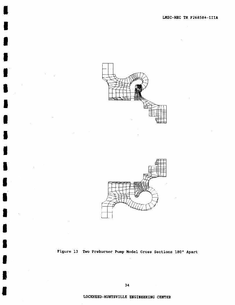
Figure 13 is a model plot that can be compared to Figure 6 (which was
obtained from the housing drawing). sections in Figure 13 is typical of other model cross sections.
The mesh shown for the two housing cross
It was decided that the support bolt holes would not be modeled f o r several reasons. First, further complexity in the model would probably
require substructuring due to ANSYS wavefront limits or Cray supercomputer core memory limits. Second, an investigation into the interaction of the support bolt hole region stresses with the vane region stresses requires model detail greater than can be offered by this model. complex in the vane region on the main pump side. model complexity created by modeling the support bolt holes outweighs the advantages gained by modeling them.
Third, the model is fairly The increase in overall
5
LOCKHEED-HUNTSVILLE ENGINEERING CENTER
c I
I I 8 I I E I 8
I 8 c I I 1 I
~
LHSC-HEC TR F268584-IIIA
Appendix A lists the job control language used to create an ANSYS FILE27
(analysis file) from the ANSYS PREP7 deck on the HSFC EADS IBN 3084QX computer. Creation of the analysis file on the HSFC EADS IBH required approximately 101 minutes CPU time. Also included in Appendix A is a listing of the job control language used to create and save the ANSYS FILE14 (the binary solution file). The HSFC EADS Cray computer classified the run which created the FILE14 as a
"HUGE2." Solution times on the Cray XMP were approximately 4000 seconds CPU.
6
LOCKHEED-HUNTSVILLE ENGINEERING CENTER
LHSC-HEC TR F268584-IIIA
3 . BOUNDARY CONDITIONS AND EXTERNAL LOADS
All nodes on the housing flange surface facing the main pump were con- strained in all degrees of freedom. No other nodes were constrained from displacement; however, all nodes were constrained from rotations by the nature of the brick elements used in the model construction.
This amounted to 240 constrained nodes.
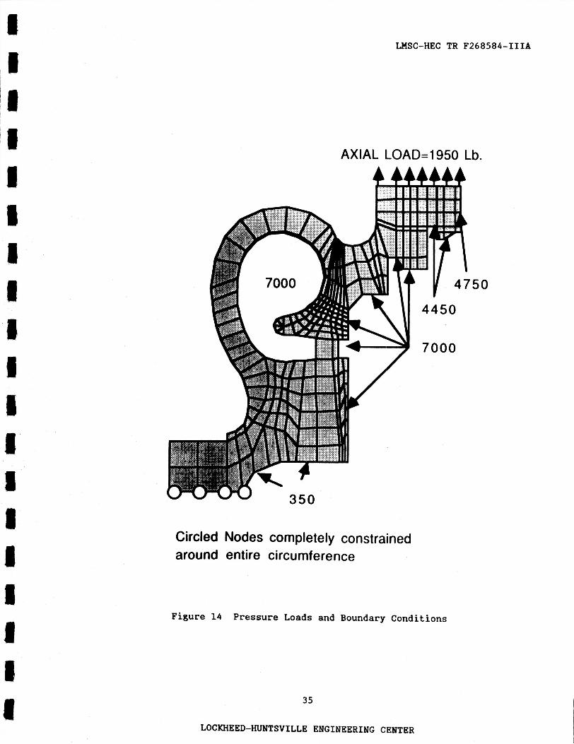
Figure 14 shows the applied pressures along with the axial load applied Internal applied pressures in the discharge pipe were to the housing inlet.
7000 psi. nodal forces. inlet and discharge pipe flanges. to these flanges using a small value (essentially zero) for the sake of the load case presented here.
In all, there were 6207 applied element pressures and 1424 applied The applied nodal forces were due to axial loads placed on the
Allowances were made to apply shear forces
No bolt loads were applied. Axial limit loads of 1950 lb and 530 lb were applied to the preburner pump inlet face and discharge pipe flange, respective-
ly. w e r e ignored relative to fluid pressures since the housing is far stiffer than the bearing components. No loads attributable to axial turboshaft motion were applied based on the assumption that the turboshaft is perfectly balanced.
Interference fit pressures caused by preburner pump bearing components
Since only a first static analysis was performed, the results presented in this report do not include torque, shear, or moments acting on the preburner pump inlet or discharge pipe flange. Limit loads for the above neglected torque, moment, and shear loads can easily be applied for a subsequent static analysis.
No hot-fire strain gage or other data indicating fluid pressures acting ‘on the forces
housing vanes and passage were available. This lack of information the estimation of pressure acting in the vane and passage regions.
7
LOCKHEED-HUNTSVILLE ENGINEERING CENTER

WSC-HEC TR F268584-IIIA
Accordingly, there is no difference between pressures applied to the suction
and pressure sides of each vane. This condition is clearly unrealistic, but it is possible that analytical or empirical methods will be applied in the
future to obtain estimates of the pressure differential across each diffuser vane. The format for applying the vane pressures allows for independently specifying pressures on the suction and pressure sides of the vanes should these pressures be determined. significant shear stress within a vane.
A large pressure differential could cause
The loading condition applied to the preburner pump housing is a Full Power Level (FPL) load case of 7000 psi applied to the inside surface of the discharge pipe, the passage, the vanes, and the housing surfaces facing the impeller. Pressures applied to the inside surface of the housing inlet ( 4 7 5 0
psi) also corresponded to FPL conditions.
In order to have the capability of running a static stress analysis at any practical ambient temperature, material properties were input as functions of temperature and then all nodal temperatures set to a uniform value. The load case presented in this report was applied at a uniform temperature of 210 OR (-250 OF).
8
LOCKHEED-HUNTSVILLE ENGINEERING CENTER

WSC-HEC TR F268584-IIIA
4, MATERIAL PROPERTIES
The HPOTP preburner pump housing is constructed of cast INCONEL 718 heat
treated in accordance with RBO170-155. The housing drawing allows for standard
grade to be used in the inlet region, whereas critical grade criteria must be
met everywhere else (see Figure 4). All material property information was ob- tained from the Rocketdyne Materials Properties Manual, except for data on the yield and ultimate strengths of the cast INCONEL 718 critical grade alloy at
the analysis temperature of 210 OR.
2, in which average yield and ultimate strengths were determined from three
specimen tests at 210 OR. The values presented at 210 OR are predicted mimimum values for the critical grade casting with heat treatment according to
STA-1.
minimum).
minimum).
These two values were obtained from Ref.
Yield strength was determined to be 125.1 ksi (average predicted Ultimate strength was determined to be 149.4 ksi (average predicted
Specification of Young's Modulus and Poisson's Ratio versus temperature
f o r use by ANSYS was obtained wholly from the Rocketdyne Materials Properties
Manual. The property data were curve fitted to cubic polynomials for use by ANSYS over the temperature range of 0 to 2000 OR. Young's Modulus and Poisson's Ratio for IWCOWEL 718 as functions of absolute temperature are
presented in Figures 15 and 16, respectively.
9
LOCKHEED-HUNTSVILLE ENGINEERING CENTER

LMSC-HEC TR F268584-IIIA
5 . STRUCTURAL ANALYSIS/RESULTS
The ANSYS HPOTP preburner pump housing finite element model was used to
determine the static stress distribution for SSME engine operation at FPL with only axial misalignment limit loads applied to the inlet and discharge flange. Margins of safety were not computed because the maximum load conditions were
not analyzed due to the absence of torque, moments, and shear acting on the inlet and discharge pipe flange. moderate to maximum allowable misalignment.
These loads would naturally arise from
Stress plots of the vane elements viewed from the inlet side of the pump housing are shown in Figures 17 through 22. Even with almost symmetric loading, the vanes exhibit an asymmetric stress state due to the asymmetric
housing geometry. Comparisons of Figures 17 and 18 and Figures 20 and 21 reveal that the axial (Sigma-2) stress is the major contributor to the maximum principal stress (Sigma-1). Table 8 lists the first four ANSYS calculated maximum Von Mises nodal stresses (Sigma-E) in the housing, their nodal loca- t-ions, and corresponding factors of safety based on yield strength. Table 9
presents the highest four maximum principal stresses and their nodal locations.
It must be emphasized that the stresses and factors of safety presented in Tables 8 and 9 do not represent the worst load case. The worst load case w i l l include all allowable misalignment loads (torque, moments, shear, and axial), along with vane stresses that will be the product of both applied oxidizer pressures and support bolt loads.
Examination of Table 9 shows that all four highest maximum principal stresses occur at the corner made by a vane element with the inlet side of the housing. Fillets were not modeled in this region because that degree of reEinement would almost certainly have necessitated substructuring. It is of greater advantage to have an unsubstructured model in the event of loads that
10
LOCKHEED-HUNTSVILLE ENGINEERING CENTER
~ ~~~~ ~~
MSC-HEC TR F268584-IIIA
produce plastic stress regions for future load cases. A further obstacle to
model refinement would be exceeding the ANSYS wavefront limit, which condition
was rapidly approached during model development.
Figures 23 through 27 show various stress components of several housing cross sections. Comparison of Figures 25 and 26 again reveals that the axial stress is the major contributor to the maximum principal stress in the region of the vanes.
Considering the result that the vane region is the area of highest stress, the question is whether the applied loads in the proximity of each diffuser vane are realistic. Certainly, the pressure differential between the pressure and suction sides of each vane, which is presently not known, has an unknown general effect on the stresses in this critical region. Additionally,
circumferential pressure variation in the housing (it should be possible to estimate this based on the geometry and fluid) will have an overall effect on a l l the vane stresses. Support bolt loads will add to the high axial stresses in localized vane regions.
11
LOCKHEED-HUNTSVILLE ENGINEERING CENTER ~~~~~ ~ ~

WSC-HEC TR F268584-IIIA
6 . SUMMARY
Maximum stresses at each cross section almost always occurred on the suct-ion side of each vane at the vane's intersection with the inlet side of the housing. The principal contributor to these stresses was the axial stress which developed as a result of the passage pressures acting on the volute geometry.
were nose end,
The stiffening webs served to reduce these stresses locally, but stresses maximized not only at the vane-housing intersection but also at each vane and tail. The corner made by the vane suction side, vane nose (or tail) and the housing inlet side was typically an area of highest stress.
Examination of the stress contours of various housing cross sections shows a well defined region at which maximum passage stresses occur. Passage stresses range from a low of about 4 ksi to a maximum of from 40 t o 50 ksi. Minimum passage stresses occur in regions where the pressure surface is convex and maximum generally where the pressure surface is concave and has the smallest radius of curvature.
Overall cross-section stresses fall as the passage grows in size. Dis- charge pipe stresses are small. The principal stress in the discharge pipe ranges from approximately 11 to 40 ksi.
Although the results for the load case presented here indicate ample factors of safety, further investigation is required. If a realistic three- dimensional (3-D) stress state within the housing is sought, then it is not enough to have a 3-D finite element model. The load variation in three dimen- sions must be known as well. angle, pressure differentials across each vane, and support bolt loads must be included to obtain the true worst case stress state and, ultimately, to improve the design.
Knowledge of passage pressures versus station
12
LOCKHEED-HUNTSVILLE ENGINEERING CENTER
LMSC-HEC TR F268584-IIIA
7 . RECOMMENDATIONS
In order to perform a complete structural analysis of the WOTP preburner
pump housing, the following would be required.
1. A static analysis should be performed which includes specified limit load moments, torques, and shear forces on both the discharge pipe flange and the pump housing inlet. The analysis of this case would provide the maximum allowable load case for the steady-state engine operation at FPL.
2. Detailed knowledge of fluid pressure within the housing, including pressure variation with station angle and within each cross section. Of special importance is the pressure drop across the vanes. This pressure drop causes shear on the vanes and adds to the overall vane stress state.
3. Pressure fluctuation magnitudes would serve to provide the means for obtaining realistic high and low cycle fatigue life estimates when used in conjunction with this ANSYS model. Knowledge of stress amplitudes and maximum stresses provides the operating stress ratio for determination of both low and high cycle fatigue life.
4. It is recommended that a modal analysis be performed using this model to determine possible resonant conditions with pressure fluctuation and impeller wake frequencies. Reference 3 also recommended this work. The 3-D pump housing model is ideally suited to providing modal frequencies for a dynamic analysis.
5 . Investigation of porosity leakage cannot be performed using two- dimensional models or the 3-D model presented here. models cannot allow for asymmetric misalignment loads or pressure variation with station angle. large and complex to include support bolt hole geometry and the details of vane nose and tail geometry. The qualities lacking in the above mentioned models are important in considering the leakage, since it has been found to occur in the region between support bolt holes and vanes. It is recommended that about half of the full 3-D model be refined and detailed as a separate model to investigate stresses in the support bolt hole-to-vane region. This would allow for application of some asymmetric misalignment loads, while still providing for detailed modeling in the region where the leakage has been discovered.
Two-dimensional
The 3-D model presented here is too
13
LOCKHEED-HUNTSVILLE ENGINEERING CENTER

LnSC-HEC TR F268584-IIIA
6 . Reference 2 provides low cycle fatigue life data for the preburner pump housing material; however, these data were obtained while testing at a stress ratio of R=-1.0. This is an unrealistic number for examination of the low or high cycle fatigue life characteristics of the preburner pump housing. In addition, the heat treatment of the specimens tested was in accordance with RAO611-020, whereas the heat treatment specification for the preburner pump housing material is RBO170-155. life in the form of a plot of strain amplitude versus reversals to failure, but the stress ratio at which these tests were performed is not given. Cyclic stress-strain data should be produced or experi- mentally determined for the housing material at a stress ratio of zero or greater than zero to avoid underprediction of housing life. This is the type of fatigue environment to which the housing is subjected during SSHE engine operation.
Reference 4 also presents a plot of low cycle fatigue
Once the above information is obtained, the following results could be achieved :
1. Prediction of low and high cycle fatigue life for the preburner pump housing
2. Prediction of maximum steady state and transient stress levels within the housing
3 . Prediction of minimum margins of safety for the preburner pump housing
4. Judgment of whether the design geometry contributes significantly to the possibility of oxidizer leakage into support bolt holes
5. Resonant conditions during engine operation in the preburner pump housing .
14
LOCKHEED-HUNTSVILLE ENGINEERING CENTER
LHSC-HEC TR F268584-IIIA
8. REFERENCES
1. Drawing RS007739, HPOTP Preburner Pump Housing.
2. Internal Letter from D.M. Haegelin to R.H. Passerini, Report No. HPR-87- 1029 (230721, Cyclic Stress-Strain Diagram for INCONEL 718, Cast, STA-1, Rockwell International, November 11, 1987.
3. Structural Audit, Action Item 0x157.
4. Internal Letter from A.P. Meisels to (Unknown), Report No. WR-87-0407 (137011, Structural Audit-Materials, Preburner Pump Volute HPOTP, INCONEL 718C, Rockwell International, May 4, 1987.
15
LOCKHEED-HUNTSVILLE ENGINEERING CENTER

~ ~~
LMSC-HEC TR F 2 6 8 5 8 4 - I I I A
T a b l e 1. KLEMENT HAT&RT.AI, AND TYPE " B E R S FOR GLOBAL ELEMENT REGIONS
T a b l e 2 ELEMENT MATERIAL AND TYPE NUMBERS FOR ELEMENTS NOT I N THE TONGUE REGTON
Table 3 ELRHENT MATERIAL AND TYPE "BISRS FOR ELEMENTS TN THE TONGUE REGTON
16
LOCKHEED-HUNTSVILLE ENGINEERING CENTER
~ ~-
LHSC-HEC TR F268584-IIIA
7 8 9 10 11 12
Table 4 NODE ANGLE LOCATIONS FOR NODES FROM -25" TO 147". EXCEPT ON DISCHARGE PIPE
10 b.c. 15 21 25
30 b.c. 35
Model Nodes on Main Pump Side Station of Vanes and Nodes on the
N u m b e r Preburner to Main Pump
14 15 16 17
2 I -2 1 3 -15
50 b.c. 55 65
70 b.c.
19 20 21 22
85 90 b.c.
95 99
I 18 I 75
24 I 110 b.c. I 25 115
26 125 27 130 b.c. 28 135
and Symmetric Inlet Region
-1 -15
27 1
57 1
75 1 -1 99
141 147
17
LOCKHEED-HUNTSVILLE ENGINEERING CENTER
LHSC-HEC TR F268584-IXIA
Nodes on Main Pump side Station of vanes and nodes on the
Number Preburner to Main Pump
Table 5 NODE ANGLE LOCATIONS FOR NODES FROM 150" TO -30", EXCEPT ON DISCHARGE PIPE
Passage Region and Symmetric
Inlet Region - Housing Flange
31 150 b.c. 153 32 155 159
18
LOCKHEED-HUNTSVILLE ENGINEERING CENTER

~~
LMSC-HEC TR F268584-IIIA
Table 6 NUMBERING SCHEME FOR NODES FROM -21" TO 147". EXCEPT FOR WEB AND FLANGE NODES
19
LOCKHEED-HUNTSVILLE ENGINEERING CENTER

~~ ~
LHSC-HEC TR F268584-IIIA
Table 7 NUMBERING SCHEME FOR NODES FROM 150" TO - 7 5 " , EXCEPT FOR WEB AND FLANGE NODES
20
LOCKHEED-HUNTSVILLE ENGINEERING CENTER

NODE REGION VON MISES STRESS (ksi)
On inlet side of vane region at 67.0
e= 870
On inlet side of housing near a 66.2
vane comer at 8 = 57'
On inlet side of vane region at 65.7
5857
F A O R OF S A F E N ON YIELD
1.87
1.89
1.90
4341
_ _ _ _ _ ~ ~~
On inlet side of vane region at
e = -90
4342
65.7 1.90 1009
On inlet side of housing at a
vane corner at 8 = -9O
On inlet side of housing at a
vane comer at 8 = 57"
On inlet side of housing at a
vane comer at 8 = 123"
On inlet side of housing at a
vane comer at 8 = 63"
LMSC-HEC TR F268584-IIIA
84.7
80.6
78.1
77.6
Table 8 NAXLHUM HOUSING VON MISES STRESSES
Table 9 MAXIMUM HOUSING PRINCTPAL STRESSES
1008 I 4341
4633
REGION I PRINCIPAL STRESS (ksi)
21
LOCKHEED-HUNTSVILLE ENGINEERING CENTER

I I I I I
I I
I I I I
I
I
w U 0
c e
- e
J
F
L
w 2 m e s c I-
/
~ ~~
LHSC-HEC TR F268584-IIIA
I 22
LOCKHEED-HUNTSVILLE ENGINEERING CENTER
rn L,
E: 0
0 V
E I2 Lc 0 -3 cd C n4 E-c K cu 0
0 .d

I I I I I I I I I I I I I I I I E c I
LHSC-HEC TR F268584-IIIA
Figure 2 Preburner Pump Housing and Preburner Pump Components
23
LOCKHEED-HUNTSVILLE ENGINEERING CENTER
I I I I I I I I I
LMSC-HEC TR F268584-IIIA
I I 1 I
Figure 3 Preburner Pump Housing View from In le t Side
24
LOCKHEED-HUNTSVILLE ENGINEERING CENTER

I I I I I I I I I I I I I I I I I I I
LMSC-HEC TR F268584-IIIA
Figure 4 Cutaway View of Preburner Pump Housing
25
LOCKHEED-HUNTSVILLE ENGINEERING CENTER

~
LHSC-HEC TR F268584-IIIA
to . 09 0’78 -0.03
,017
Figure 5 Orientation of Discharge Pipe with respect to Pump Housing Volute Passage
26
LOCKHEED-HUNTSVILLE ENGINEERING CENTER
9.84
I
MSC-HEC TR F268584-IIIA
b 4.05 - Figure 6 Overall Dimensions of the Preburner hrmp Housing
27
LOCKHEED-HUNTSVILLE ENGINEERING CENTER

a I 4 T I
~~
LHSC-HEC TR F268584-IIIA
Passage Region
Ntric
Figure 7 Cross-Section Regions of the Model
28
LOCKHEED-HUNTSVILLE ENGINEERING CENTER
inlet
LMSC-HEC TR F268584-IIIA
Figure 8 Preburner Pump Housing Model Plot, View A from Inlet Side
29
LOCKHEED-HUNTSVILLE ENGINEERING CENTER

MSC-HEC TR F268584-IIIA
Figure 9 Preburner Pump Housing Model P lo t , V i e w B from I n l e t S i d e
30
LOCKHEED-HUNTSVILLE ENGINEERING CENTER
~~~~ ~ ~ _ _ _ _ _ _ _ _ _ _ _ _ ~ ~
LMSC-HEC TR F268584-IIIA
Figure 10 Preburner Pump Housing Model, View from Main Pump Side
31
LOCKHEED-HUNTSVILLE ENGINEERING CENTER

~~
LHSC-HEC TR F268584-IIIA
Figure 11 Cutaway View of Preburner Pump Housing Model
32
LOCKHEED-HUNTSVILLE ENGINEERING CENTER

LHSC-HEC TR F268584-ITIA
Figure 12 Diffuser Vane Elements
33
LOCKHEED-HUNTSVILLE ENGINEERING CENTER
c E I i I 8 I I E I 1;
I a
I 8 I
a
LHSC-HEC TR F268584-IIIA
m
m
Figure 1 3 Two Preburner Pump Model Cross Sections 180" Apart
34
LOCKHEED-HUNTSVILLE ENGINEERING CENTER
Ir II I # I 1 E I IC I I I I 8 1
8
LHSC-HEC TR F268584-IIIA
AXIAL LOAD=1950 Lb.
50
Circled Nodes completely constrained around entire circumference
Figure 14 Pressure Loads and Boundary Conditions
35
LOCKHEED-HUNTSVILLE ENGINEERING CENTER

WSC-HEC TR F268584-IIIA
3.2-7
3.0Oe+7
2 . 8 0 ~ 7
2 . 6 0 ~ 7
a 4 2.1-7 a
a 2.2-7 >
'?I - - 9
P
2.ooe*7
1.008+7
0 4 00 eo0 1200 1600 2000 2400
Absolute Temperature (deg R)
Figure 15 INCONEL 718 Young's Modulus as a Function of Absolute Temperature (Rankine)
0 4 0 0 eo0 1200 1600 2000 2 4 0 0
Absolute Temperature (deg R)
Figure 16 INCONEL 718 Poisson's Ratio as a Function of Absolute Temperature (Rankine)
36
LOCKHEED-HUNTSVILLE ENGINEERING CENTER

LJ!4SC-HEC TR F268584-IIIA
ORIGINAL PAGE COLOR PHOTOGRAPH
37
LOCKHEED-HUNTSVILLE ENGINEERING CEUTER

MSC-HEC TR F268584-IIIA
n VI VI a, Ll c, cn d (D
.r( X 4
N I
W
z 00
cn
a, m .r(
cn c, a, rl C w
.r(
.I
Ll cer a Q) 3 Q)
> rn Q) C m =r
00 rc a, t 3 00
ra
.d
.r(
LOCKHEED-"TSVILLE eblGIIseERIISG CENTER

'MSC-HEC TR F268584-IIIA
v) Mb) v)
W
e
I
39
LOCWIEBD-HUUTSVILLE BNGINEERIEG CENTER

WZSC-HEC TR F268584-IIIA
4 0
LOCKHEED-HUNTSVILLE EWGIMEERIMG CEWTER

W C - H E C TR F268584-IIIA
I 8
tn
A
41
LOCKHEED-"TSVILLE ENGINEERING CENTER

W C - H E C TR F 2 6 8 5 8 4 - I I I A
ORlGlNAh PAGE C!3:.OR PHOTOGRAPH
'I
42
LOCKHEED-"TSVILLE ENGINEERING CENTER

LBC-HEC TR F268584-IIIA
43
LOCKHEED-HUNTSVILLE ENGINEERING CENTER

W C - H E C TR F 2 6 8 5 8 4 - I I I A
ORIG!NAL PAGE COLOR PHOTOGRAPH
v) MQ) v)
W-I
II > *
M cu cu II t- v)
IEL “““11111
44
LOCKHEED-HUNTSVILLE ENGINEERING CENTER

I 1 I I I I I
I 'I ,I
1 I I I I I I I
v) m v ) M cu cu II
el- II v) >- *a
cu e M II G x
m e
II G * H
I W P
I n M
LHSC-HEC TR F268584-IIM
ORIGINAL PAGE COLOR PHOTOGRA&
4s
LOCKHEED-HUNTSVILLE ENGINEERING CENTER
LHSC-HEC TR F268584-IIIA
46
LOCKHEED-HUNTSVILLE ENGIlEERIlG CENTER

M
d
v) * v) 2 U
M cu cu II I- v)
D c1
LnSC-HEC TR F268584-IIIA
ORIGINAL PAGE COLOR PHOTOGRAPH
* I I L
W I- 3 4 0 > e E 3 e
47
LOCKHEED-HUNTSVILLE ENGINEERING CENTER