space polymers and ionomers in soil-cement
TRANSCRIPT

Louisiana State UniversityLSU Digital Commons
LSU Historical Dissertations and Theses Graduate School
1967
Space Polymers and Ionomers in Soil-Cement.Howard Morelock Elder JrLouisiana State University and Agricultural & Mechanical College
Follow this and additional works at: https://digitalcommons.lsu.edu/gradschool_disstheses
This Dissertation is brought to you for free and open access by the Graduate School at LSU Digital Commons. It has been accepted for inclusion inLSU Historical Dissertations and Theses by an authorized administrator of LSU Digital Commons. For more information, please [email protected].
Recommended CitationElder, Howard Morelock Jr, "Space Polymers and Ionomers in Soil-Cement." (1967). LSU Historical Dissertations and Theses. 1332.https://digitalcommons.lsu.edu/gradschool_disstheses/1332

This dissertation has been microfilmed exactly as received 6 7 -1 7 ,3 1 5
ELDER, Jr., Howard Morelock, 1941- SPACE POLYMERS AND IONOMERS IN SOIL-CEMENT.
Louisiana State University and Agricultural and Mechanical College, Ph.D., 1967 Engineering, chemical
University Microfilms, Inc., Ann Arbor, Michigan

(?' Copyright byHOWARD MORELOCK ELDER, JR.1968

SPACE POLYMERS AND IONOMERS IN
SOIL-CEMENT
A Dissertation
Submitted to the Graduate Faculty of the Louisiana State University and
Agricultural and Mechanical College in partial fulfillment of the requirements for the degree of
Doctor of Philosophy
in
The Department of Chemical Engineering
byHoward Morelock Elder, Jr.
B.S., Louisiana Polytechnic Institute, 1963 M.S., Louisiana State University, 1965
August, 1967

ACKNOWLEDGMENT
This research project was carried out under the direction of
Dr. Clayton D. Callihan, whose guidance and inspiration is respectfully
acknowledged. Special appreciation is extended to Professor Ara Arman
for his invaluable consultation and to the Department of Civil Engi
neering for the use of its soil mechanics laboratory.
Special thanks are due Professor Harry Richardson and Dr.
Robert C. Mcllhenny for their assistance and to the LSU Nuclear Science
Center for the use of its facilities. Acknowledgment is made to Dr.
Paul Koenig and to the Department of Chemistry for use of its x-ray
diffraction equipment, and to Dr. Ray E. Ferrell, Jr. and Dr. Clara Ho
for technical consultation. The assistance of Dr. Larry Morton is
acknowledged and the LSU Computer Center is acknowledged for use of its
facilities in analyzing data. Special appreciation is extended to Mr.
David 0. Howe of the Ideal Cement Company for all assistance rendered.
The following companies are sincerely thanked for materials contributed
during the course of this research: The Dow Badische Company, Hercules
Incorporated, The Borden Chemical Company, The Portland Cement Associa
tion, Chembond Corporation, and Reichold Chemicals, Incorporated.
Sincere thanks are due Mrs. Alma Oliver, Miss Hazel LaCoste,
and Mrs. Ruth Albright, department secretaries, for their continued
cheerful assistance and to Mr. L. M. Carpenter and Mr. Larry Veilleux
for mechanical support. A special thanks goes to the many undergradu
ate students who assisted with this work at various times.

Acknowledgment is made to Dr. Elvin J. Dantin of the LSU
Division of Engineering Research for a research assistantship and to
the Dow Chemical Company for a Fellowship during the course of this,
work.
Sincere thanks is due the Dr. Charles E. Coates Memorial
Fund of the LSU Foundation for paying the publication costs of this
dissertation.
The author wishes to express his indebtedness to Mrs. Marion
McClure and Mrs. Ruth Albright for their patience and di-ligence in
typing this manuscript.
Without the encouragement and sacrifice of my wife, Sandra,
this undertaking would not have been possible.

TABLE OF CONTENTS
'-foge
LIST OF T A B L E S ....................................................... vi
LIST OF FIGURES......................................................... viii
ABSTRACT.............................................................. xi
INTRODUCTION ......................................................... 1
General Discussion ........................................ 1
Previous Studies .............................................. 3
General .......................................... 3Chemical Additives to Soil Cement ...................... 4Additives to Other Cement-Containing Systems ........... 5
Background Theory and Theory of Strength Generation ......... 8
Established Theory ........................................ 8The Nature of Strength Generation ...................... 22Proposed Theory . . . . . ........... 26
Experimental Approach .......................................... 32
Experimental Apparatus and Procedures ........................ 3A
Compressive Strength Samples ............................. 34Data Analysis ............................ 40
R e f e r e n c e s ....................................... 41
EXPERIMENTAL RESULTS ................................................. 43
Space P o l y m e r s ................................................. 43
Urea-Formaldehyde in Soil-Cement ........................ 43Phenol-Formaldehyde Samples ............................. 44
Nonpolymeric Carboxylic Acid Molecules ......... . 45
Molding Reproducible Samples ............................. 45Oxalic Acid S a m p l e s ...................................... 49Terephthalic Acid Samples ............................... 58Cyclopentanetetracarboxylic Acid Samples ............... 61
Polymeric Carboxylic Acid Ionomers ........................... 65iv
Page
Monomers Containing Pendant Carboxyl Groups .................. 102
Preparation and Reaction of Tobermorite .................. 130
References . . . . . . . . . ................................... 134
DISCUSSION OF RESULTS ................................................. 135
Space Polymers in Soil-Cement............................... 135Nonpolymeric Carboxylic Acid Molecules .................. 136Oxalic Acid and Calcium Oxalate Samples .................. 137Terephthalic Acid Samples ................................. 139Cyclopentanetetracarboxylic Acid Samples.................... 140Polymeric Carboxylic Acid Ionomers. . . .................. 140Monomers Containing Pendant Carboxyl Groups ........... . 146
CONCLUSIONS.............................................................. 153
RECOMMENDATIONS ....................................................... 157
BIBLIOGRAPHY.............................................................. 159
APPENDICES
A Physical Characteristics of T-10 S o i l ....................... 162Portland Cement Composition ............... . 162
B LSU Pool-Type Cobalt 60 Irradiator............................164
C Pressure Autoclave for Making Tobermorite ................ 165
D Calculations ............................................... 166
V I T A ..................................................................... 170
v

LIST OF TABLES
TABLE Page
I Some Characteristics of Soil Separates ....................... 9
II Strengths of T-10 Silty-Clay-Cement........................... 48
III Moisture-Density Data for T-10 Silty-Clay-Cement at750 PSI......................................................... 51
IV Moisture-Density Data for T-10 Silty-Clay-Cement at1250 P S I ....................................................... 53
V Moisture-Density Data for Samples Containing Oxalic Acid . . 56
VI Strength of Oxalic Acid-Containing Samples .................. 57
VII Strengths of Soil-Cement Samples Containing TerephthalicA c i d ........... 58
VIII Moisture-Density Data for Samples Containing TerephthalicA c i d ............................................................ 60
IX Moisture-Density Data for Samples Containing CPTA............ 83
X Moisture-Density Data for Samples Containing 0.41% Na-CMC. . 87
XI Strengths of Samples Containing 0.4% Na-CMC.................. 70
XII Compressive Strength Data for Figure.20...................... 72
XIII Compressive Strength Data for Figure 21...................... 74
XIV Compressive Strength Data for Figure.22...................... 76
XV Compressive Strength Data for Figure 23...................... 78
XVI Compressive Strength Data for Figure 24...................... 80
XVII Modulus Data for Figure 2 5 .................................... 82
XVIII Modulus Data for Figure 2 6 .................................... 85
XIX Moisture-Density Data for Figure 27. ....................... 88
XX Modulus Data for Figure 2 8 .................................... 90
vi

TABLE
XXI Modulus Data for Figure 29.................................. 92
XXII Moisture Absorption Data for Figure 30............. 95
XXIII Moisture Absorption Data for Figure 31.................... 97
XXIV Moisture Absorption Data for Figure 32.................... 99
XXV Moisture-Density Data for Figure 3 3 ....................... 101
XXVI Moisture-Density Da'ta for Acrylic Acid Samples............. 112
XXVII Modulus Data for Samples Containing Acrylic Acid.......... 115
XXVIII Moisture Absorption Data for Figure 37.................... 119
XXIX Moisture Absorption Data for Figure 38.................... 121
XXX Moisture Absorption Data for Figure 39.................... 123
XXXI Moisture Absorption Data for Figure 40.................... 125
XXXII Moisture Absorption Data for Figure 41. . . . . . . . . . 127
XXXIII Moisture Absorption Data for Figure 42.................... 129
vii

LIST OF FIGURES
FIGURE Page
1. Relative Surface Areas of Soil Particles .................. 10
2 The Ionic Double-Layer on a Crystalline Clay Micelle. . . . 13
3 Crystal Structure of Kaolinite and Montmorillonite Clays. . 14
4 The U.S. Department of Agriculture Textural SoilClassification Chart.......................................... 16
5 Moisture-Density Relation .................................... 23
6 Excluded Volume and Shear Forces in Particulate Bodies. . . 24
7 Polymer-Soil-Cement Structure ............................... 31
8 Equipment Used in Making Compressive Strength Samples . . . 35
9 Molding and Compacting Equipment Used to Make Samples . . . 37
10 Molding and Testing Equipment ............................... 38
11 Strengths of T-10 Silty-Clay-Cement . . .................. 47
12 Moisture-Density Relation for T-10 Silty-Clay-Cementat 750 Psi............................ 50
13. Moisture-Density Relation for T-10 Silty-Clay-Cementat 1250 Psi................................................. 52
14 Moisture-Density Relation for Oxalic Acid ContainingSamples at Equal Equivalents of Cement and A c i d ........ 55
15 Moisture-Density Relation for Terephthalic Acid Containing Samples at Equal Equivalents of Cement andAcid.............. 59
16 Moisture-Density Relation for CPTA Containing Samplesat Equal Equivalents of CPTA and C e m e n t ................. 62
17 Fully Cured Standard Soil-Cement and Sample ContainingCPTA......................................................... 64
18 Moisture-Density Relation for Samples Containing 0.41Weight % Na-CMC Molded at 750 Psi........................ 66
viii

FIGURE Page
19 Compressive Strength of Samples Containing 0.4% Na-CMCat 7 and 28 Day Cure P e r i o d s ................................ 69
20 Seven Day Wet Strength of Samples Containing 0.41 Weight% Na-CMC with Molding Liquid of Different pH Values. . . . 71
21 Seven Day Wet-Dry Strength of Samples Containing 0.41 Weight % Na-CMC with Molding Liquid of Different pHV a l u e s .................................................... 73
22 Twenty-eight Day Wet Strength of Samples Containing 0.41 Weight % Na-CMC with Molding Liquid of Different pHV a l u e s ......................................................... 75
23 Twenty-eight Day Wet-Dry Strength of Samples Containing 0.41 Weight % Na-CMC with Molding Liquid of DifferentpH Values....................................................... 77
24 Twenty-eight Day Ambient Strength of Samples Containing 0.41 Weight % Na-CMC with Molding Liquid of DifferentpH Values....................................................... 79
25 Effect of Molecular Weight on Modulus of Elasticity. . . . 61
26 Effect of Polymer Concentration of Modulus of Elasticity . 64
27 Moisture-Density Relation for Samples Containing 0.69Weight % Na-CMC Molded at 750 Psi........................... 67
28 Effect of pH on Modulus of Samples Containing 0.41Weight % Na-CMC......................... 69
29 Effect of Curing Time on Modulus of Samples Containing0.41 Weight % N a - C M C ......................................... 91
30 Moisture Gain at Different pH Values of Samples Containing 0.41 Weight % Na-CMC Cured Under Seven DayWet Conditions................................................ 94
31 Moisture Gain at Different pH Values of SamplesContaining 0.41 Weight % Na-CMC Cured Under Seven Day Wet-Dry Conditions ........................................... 96
32 Moisture Gain at Different pH Values of Samples Containing 0.41 Weight % Na-CMC and Cured Under 28Day Wet-Dry Conditions........... 98
ix

FIGURE
33 Moisture-Density Relation for Soil-Cement Containing0.35 Acidified Carboxymethyl Cellulose .................... 100
34 Even Swelling in a Well Mixed Sample Containing AcrylicA c i d .......................................................... 107
35 Moisture-Density Relation for Samples Containing Equal Equivalents of Acrylic Acid and C e m e n t .................... H I
36 Modulus Curves of Samples Containing Acrylic Acid andof Fully Cured Coil-Cement .................................. 114
37 Moisture Absorption vs. Cement/Acrylic Acid Ratio atConstant Acid Content........................................ 118
38 Seven Day Moisture Absorption vs. Cement/Acrylic AcidRatio at Constant Acid C o n t e n t ............................. 120
39 Fourteen Day Moisture Absorption vs. Cement/AcrylicAcid Ratio at Constant Acid Content........................ 122
40 Thirty-Minute Moisture Absorption vs. Ca(OH)2 /AcrylicAcid Ratio at Constant Acid Content........................ 124
41 Seven Day Moisture Absorption vs. Ca(OH)2 /Acrylic AcidRatio at Constant Acid C o n t e n t ............................. 120
42 Fourteen Day Moisture Absorption vs. Ca(OH)2/AcrylicAcid R a t i o .................................................... 128
43 X-Ray Diffractograms of Tobermorite and Freshly Mixed Tobermorite and Acrylic A c i d .................. 132
44 X-Ray Diffractograms of Tobermorite-Acrylic AcidMixture After Different Cure Periods ....................... 133
x

ABSTRACT
The research work discussed in this dissertation was performed
to study the effects of space polymers and ionomers on soil-cement. As
used in this work, an ionomer is defined as a polymer formed when car
boxylic acid functional groups from two different backbone chains are
ionically crosslinked by a metallic cation or when a single carboxylic
acid functional group is chemically attached to a metallic cation
present in the soil or cement particles. The physical properties of the
soil-cement systems measured in order to evaluate performance were: un
confined compressive strength, modulus of elasticity, and moisture ab
sorption. To eliminate soil type as a major variable, all work was
done with one soil, a silty clay.
The two space polymers investigated were urea-formaldehyde
and phenol-formaldehyde. Each of these was mixed into a typical soil-
cement composition, cured under specified conditions, and examined
visually and by hand. Neither of these space polymers appeared to be
compatible at high concentrations with portland cement. No numerical
data were taken on these systems.
For all other systems investigated, soil-cement cylinders
approximately 4.3 inches high by 2.25 inches in diameter were molded
by static compression in a steel cylinder having movable pistons at each
end. These compacted samples were removed hydraulically from the mold
ing cylinder and cured under one of five sets of cure conditions. Cur
ing periods were for either seven or twenty-eight days. After the
prescribed cure, the cylinders were tested in unconfined compressionxi

during which stress versus strain data were recorded. Systems were com
pared by comparing samples molded at optimum moisture content which re
sulted in maximum density.
Three systems containing soil-cement modified with simple
multifunctional carboxylic acid compounds in concentrations chemically
equivalent to the portland cement in the system were compared. Tlis
acids used were oxalic acid, terephthalic acid, and cyclopentanetetra-
carboxylic acid.
The presence of these acids evidently interfered with the
formation of the cement hydration lattice because each of the acid-con
taining samples exhibited drastically reduced compressive strengths.
Carboxymethyl cellulose in salt and acid form were investi
gated as representative of polymeric additives capable of forming iono
mers. In the acidified form, carboxymethyl cellulose markedly reduced
the strength of soil-cement. The sodium salt (Na-CMC) caused a strength
reduction of approximately 20 percent when added in low concentration
(0.41 weight %). Increasing amounts of Na-CMC did show improved prop
erties indicating an initial disruption of the cement hydration lattice
which was partially offset by the strength contribution of the polymer
at higher concentrations.
Acrylic acid was selected as representative of a monomer
capable of in situ polymerization to an Ionomer. Investigations with
this system indicated that the strength of a soil-cement system can be
improved by filling all available free volume with a strong polymeric
binder exhibiting viscoelastic behavior. It was shown that for such a
system the customarily plotted moisture-density curve has little valuexii

in predicting sample strength. This would indicate that the Mohr-
Coulomb theory of shear failure may only hold when the binding mattrix
is inelastic. The combined results of all ionomeric systems showed
that ionomers are water sensitive and that in order to get high wet
strengths, some provision must be made to decrease the natural moisture
sensitivity. At high concentrations of acrylic acid, the 28 day
strength of standard soil-cement was almost doubled. Calculations
showed that a freshly compacted soil-cement cylinder contains about 17
percent free volume which increases as moisture evaporates from the sam
ple. Samples of maximum density which contained acrylic acid had 16
percent free volume but this free volume was not noticeably increased
as the samples were allowed to cure.

INTRODUCTION
General Discussion
The rapid advancements in modern engineering have dictated
that the engineer be able to control the physical properties of the
soil upon which he works. The term "soil stabilization" is applied to
the process of improving the engineering properties of natural soils
in order that they might be used successfully as structural materials.
Both chemical and mechanical methods of stabilization exist and commonly
are used together. Chemical stabilization, which is of most interest
in this dissertation, is accomplished by the addition of chemical
admixtures to the soil.
Chemical admixtures can react with and stabilize soils in
three ways, the most common of which is by bonding or cementing the
soil particles together. Once the particles are bound together, the
mixture is more able to withstand the detrimental forces of weather,
moisture, and load application. Admixtures can also act as water
proofing agents, which, when added to soils, tend to impart their
hydrophobic quality to the mixture, thereby reducing the destructive
effects of water flow through the system. "Unlike the bonding agents,
whose effectiveness increases with the quantity used, waterproofing
agents usually attain maximum effectiveness when used in small quan-(1)tities— two percent or less by weight of the treated soil."'' y A third
common chemical stabilization mechanism is the addition of trace quan
tities of a surface-active agent which interacts only with the surfaces
of the soil particles. The surfactant alters the electrical potential

at the particle surfaces, allowing a denser packing with equal compac-
tive efforts.
The list of materials which have been tested as soil stabiliz
ing agents is almost endless. Some general classifications are: inor
ganic cementing materials such as portland cement and lime, resinous
waterproofing materials such as commercially powdered rosin and par
tially neutralized Tall oil, resinous bonding materials such as aniline-
furfural and phenol-formaldehyde, inorganic compounds such as sodium
hydroxide and sodium carbonate, and various bituminous materials. Even
with such an imposing list of applicants, no stabilizing agent has been
found which will stabilize all soils under all conditions. The one
additive which has met with greater success than any other soil-stabil
izing material is portland cement. A mixture of soil and portland cement
is commonly referred to as "soil-cement." Cement usually constitutes
between six and sixteen weight percent of a soil-cement system. The term
"soil" as used in this work refers to any mixture of the soil components:
gravel, sand, silt, and clay.
In spite of its popularity in road base and airport runway
construction, soil-cement fails in several respects. Portland cement,
although a good bonding agent, does not impart water-repellent charac
teristics to the treated soil and in some cases is not even a durable
admixture.^ Although performing well under a wide variety of conti-
tions, portland cement is not recommended for stabilizing all types of(2)soils, as in the case of highly plastic soils. In these respects,
soil-cement systems need improvement. Because of their excellent strength
and moisture resistance, it is natural that high polymers have been

considered as soil stabilizing agents both by themselves and in con
junction with portland cement. Theoretically, polymers offer many
advantages as soil stabilizers and soil-cement admixtures. In the
simplest interaction with the soil, the polymer network acts only as
a binder and the soil as an inert filler. Even in this simple rela
tionship, the polymer imparts its characteristics to the mixture. If,
in addition, a chemical bond were established between the soil parti
cles and the polymer matrix, a more stable system should be formed.
The necessary bond formation is possible if ionomers* are formed either
before or following polymerization. Where cement hydration lattices
are present, as in soil-cement, the possibility also exists of bonding
the polymer matrix to the hydration lattice. The addition or formation
of an ionomer in the system would allow a bond to be established between
the polymer and the soil or hydration lattice. An ionomer is the re
sult of a neutralization reaction between acidic carboxyl groups in the
polymer and basic sites, usually calcium ions, in the soil or cement.
Thus an ionic bond can be formed between the polymer network and the
cemented soil particles.
Previous Studies
General
The last twenty years have seen considerable accomplishments
made in finding additives which will improve the physical properties of
soil-cements. For economic reasons essentially all of the additives
have been relatively inexpensive and added in small amounts. Most of
those researchers trying to take advantage of the desirable properties
* An ionomer is formed when a metallic cation reacts with pendant carboxyl groups from two adjacent polymer chains establishing an jxnic bond between the chains.

of high polymers by incorporating them into soil-cement compositions
have therefore added only small amounts (usually less than ten percent
polymer based on soil dry weight) and obtained very modest improvements
in physical properties. The "ideal" additive to soil-cement has not
been found.(3)Winterkorn has stated that the theoretical goal of an
organic binder is to "deprive the primary and secondary* clay particles
of their water-affinity and to cement these particles together." This
goal might be accomplished by use of an ideal binder which is "hydro-
phobic and possesses greater affinity to the internal soil surface in
volved than is possessed by water: it (the ideal binder) is resistant
to oxidation and to attack by soil bacteria and fungi; it is applicable
as a liquid of low viscosity and forms a plastic or solid cement within
reasonable and controllable time." It has not been satisfactorily shown
whether polymers are required to meet these criteria or whether simple
organic molecules will perform equally well.
Chemical Additives to Soil-Cement
In work that has now become classical, M a i n f o r t ^ tested
dozens of chemical admixtures to soils and soil-cement. His primary
interest in soil-cement was to find an additive which would result in a
more generally applicable and durable treatment and one which would give
soil-cement water repellent properties. He found that the effectiveness
of a particular additive varied with the soil type and that no chemical
additives tested gave large improvements in physical properties. The
* A secondary soil particle is a particle formed by cementing primary soil particles into a cluster around grains of the cementing agent.

additives improving soil-cement properties were two chlorinated diphenyls
and three synthetic resinous bonding agents of the polyterpene and.
coumarone-indene families. It was concluded that real advancements in
additive technology would come only after a comprehensive study of
basic soil composition and of the reactions involved in the combination
of the various soil components with chemical admixtures.
Research on chemical additives to soil-cement at the M.I.T.
Soil Stabilization Laboratory has been described by Lambe and M o h . ^
The strength-imparting effect of twenty-nine additives, including
dispersants, synthetic resins, waterproofing agents, and several salts
and alkalis, was investigated. "The most effective additives were
sodium carbonate, sodium hydroxide, sodium sulfate, and potassium per
manganate." When one percent additive was added to a soil-cement con
taining five percent Type I* cement, the compressive strength was im
proved 150 percent in some soils. No detailed reaction mechanisms were
presented and it was stated that they were not well understood.
More recent research reported by Laguros and Davidson
indicates that seven and twenty-eight day unconfined compressive
strengths increased when calcium and magnesium ions were added to
alkaline soils of high clay content.
Additives to Other Cement-Containing Systems
Concrete Additives
A number of polymer systems have been used with systems con
taining portland cement. Tyler and Drake^^ have shown that styrene-
butadiene and vinyl acetate latex systems when added to concrete will
* Type I cement is the most common type of portland cement. Other types are available— for example, quick-setting cements.

give improved adhesion to previously laid concrete, greater dry strength,
and increased abrasion resistance. The compressive strength of a latex-
modified cement containing twenty percent latex solids by weight in
creased about ten percent over a regular wet-cured cement. Each of
these latex systems, however, produced a water-sensitive product. When
wet, the strength was lower than an unmodified concrete. Two water-
soluble resins which strengthen the normal cement structure were found—
a highly hydrolyzed poly (vinyl acetate) resin and low molecular weight
polyacrylates which possess some ability to crosslink. However, each
of these also was found to have continued water-sensitivity after drying.
The authors feel that, generally, chemical additives promote
the natural reaction of cement and do not strengthen the mixture in them
selves. This, they feel, explains their effectiveness in small amounts.
Polymeric additives, in contrast to simple molecules, strengthen and
improve cements by imparting some of their own physical properties to
the cement system. At the proper level of additive, polymer-cement-
polymer chains are formed.
Work along similar l i n e s h a s shown that if acrylamide-
acrylic acid copolymers of medium to high molecular weights and contain
ing certain critical ratios of acrylamide to acrylic acid are incorporated
into cements in the form of their alkali metal salts, the loss of fluids
from the cement when put under considerable hydrostatic pressure is
greatly reduced. The optimum concentration of the copolymer in such
service was found to be 0.3% to 5.0% of the dry weight of the cement.
These techniques could be applied to cementing of deep oil and gas wells
and the grouting of subterranean foundations.
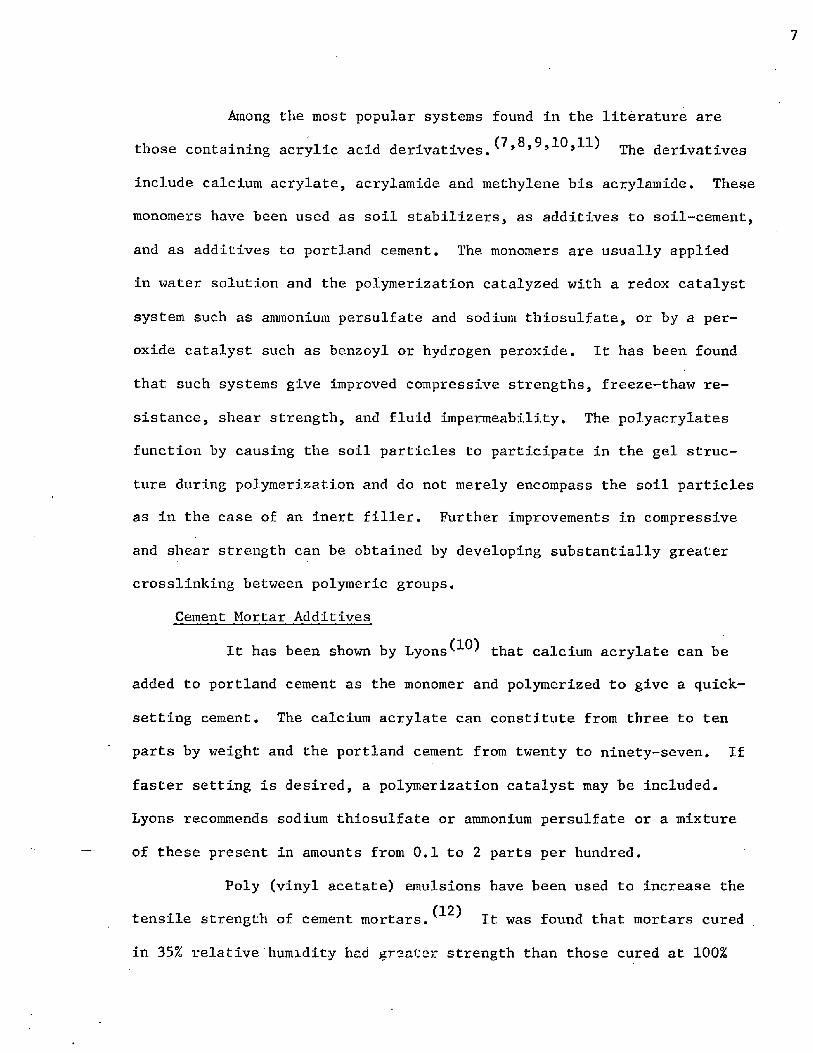
Among the most popular systems found In the literature are
those containing acrylic acid derivatives.^>®>9,10,11) derivatives
include calcium acrylate, acrylamide and methylene bis acrylamide. These
monomers have been used as soil stabilizers, as additives to soil-cement,
and as additives to portland cement. The monomers are usually applied
in water solution and the polymerization catalyzed with a redox catalyst
system such as ammonium persulfate and sodium thiosulfate, or by a per
oxide catalyst such as benzoyl or hydrogen peroxide. It has been found
that such systems give improved compressive strengths, freeze-thaw re
sistance, shear strength, and fluid impermeability. The polyacrylates
function by causing the soil particles to participate in the gel struc
ture during polymerization and do not merely encompass the soil particles
as in the case of an inert filler. Further improvements in compressive
and shear strength can be obtained by developing substantially greater
crosslinking between polymeric groups.
Cement Mortar Additives
It has been shown by Lyons that calcium acrylate can be
added to portland cement as the monomer and polymerized to give a quick-
setting cement. The calcium acrylate can constitute from three to ten
parts by weight and the portland cement from twenty to ninety-seven. If
faster setting is desired, a polymerization catalyst may be included.
Lyons recommends sodium thiosulfate or ammonium persulfate or a mixture
of these present in amounts from 0.1 to 2 parts per hundred.
Poly (vinyl acetate) emulsions have been used to increase the(12)tensile strength of cement mortars. It was found that mortars cured
in 35% relative humidity had greater strength than those cured at 100%
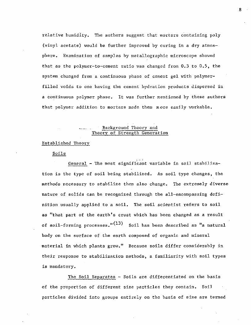
relative humidity. The authors suggest that mortars containing poly
(vinyl acetate) would be further improved by curing in a dry atmos
phere. Examination of samples by metallographic microscope showed
that as the polymer-to-cement ratio was changed from 0.3 to 0.5, the
system changed from a continuous phase of cement gel with polymer-
filled voids to one having the cement hydration products dispersed in
a continuous polymer phase. It was further mentioned by these authors
that polymer addition to mortars made them more easily workable.
. Background Theory andTheory of Strength Generation
Established Theory
Soils
General - The most significant variable in soil stabiliza
tion is the type of soil being stabilized. As soil type changes, the
methods necessary to stabilize them also change. The extremely diverse
nature of solids can be recognized through the all-encompassing defi
nition usually applied to a soil. The soil scientist refers to soil
as "that part of the earth’s crust which has been changed as a result
of soil-forming p r o c e s s e s S o i l has been described as "a natural
body on the surface of the earth composed of organic and mineral
material in which plants grow." Because soils differ considerably in
their response to stabilization methods, a familiarity with soil types
is mandatory.
The Soil Separates - Soils are differentiated on the basis
of the proportion of different size particles they contain. Soil
particles divided into groups entirely on the basis of size are termed

soil ’’separates." Any soil composed mainly of mineral matter may be
separated into these groups or separates. In Table I are given the
names of the separates, their diameters (assuming all particles are
spheres of maximum diameter), and their surface area. Particle size
is important because it controls the total surface area available for
chemical reaction and for secondary bonding and these, in turn, con
trol the reaction of a soil to all stabilization procedures. Based
on the proportion of the different separates they contain, soils are
divided into textural classes. To understand why these classes act
as they do, it is essential to know the properties of the different
soil separates.
TABLE I
SOME CHARACTERISTICS OF SOIL SEPARATES
NameDiameter,*Millimeters
Surface Area in 1 Gram,
Sq. Centimeters
Fine gravel 2.00-1.00 11.3
Coarse sand 1.00-0.50 22.7
Medium sand 0.50-0.25 45.4
Fine sand 0.23-0.10 90.7
Very fine sand 0.10-0.05 226.9
Silt 0.05-0.002 453.7
Clay below 0,002 11,352.5
* As established by U. S. Department of Agriculture.

10
Because of their relatively small surface areas as compared
to equal weights of silt and clay, the sand separates can be thought of
as one separate. Since it is surface area which controls the chemical
and physical activity of a soil, the presence of sand influences these
little unless some of the sand particles are appreciably soluble com
pounds such as calcium or magnesium carbonate. As a result of this
inactivity, sand serves almost entirely as a framework around which the
active part of the soil (silt and clay) is associated, and each sand
particle functions separately.
The largest silt particles, because of their size, are similar
to the fine sands and hence take little part in the chemical activities
of soils. However, as the center of the silt size range is approached,
definite changes can be observed in most soil properties. (See Figure 1.)
SurfaceAreaper
Gram
Figure 1. Relative Surface Areas of Soil Particles
ColloidalClay
11
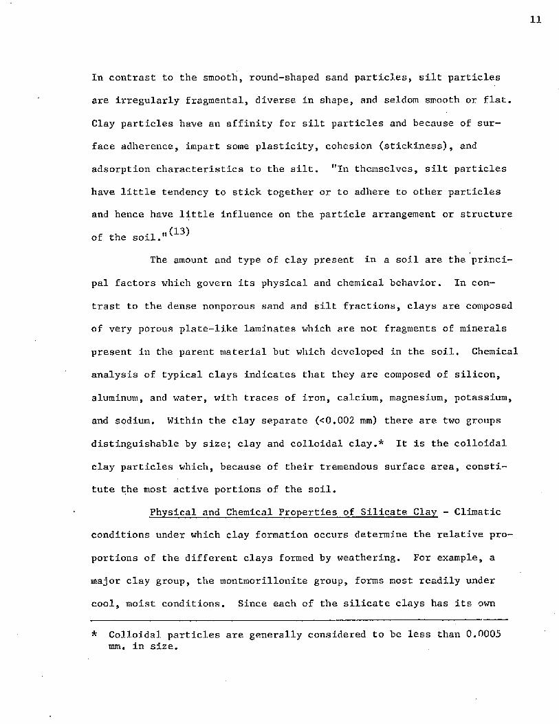
In contrast to the smooth, round-shaped sand particles, silt particles
are irregularly fragmental, diverse in shape, and seldom smooth or flat.
Clay particles have an affinity for silt particles and because of sur
face adherence, impart some plasticity, cohesion (stickiness), and
adsorption characteristics to the silt. "In themselves, silt particles
have little tendency to stick together or to adhere to other particles
and hence have little influence on the particle arrangement or structure
of the soil."^13)
The amount and type of clay present in a soil are the princi
pal factors which govern its physical and chemical behavior. In con
trast to the dense nonporous sand and silt fractions, clays are composed
of very porous plate-like laminates which are not fragments of minerals
present in the parent material but which developed in the soil. Chemical
analysis of typical clays indicates that they are composed of silicon,
aluminum, and water, with traces of iron, calcium, magnesium, potassium,
and sodium. Within the clay separate (<0.002 mm) there are two groups
distinguishable by size; clay and colloidal clay.* It is the colloidal
clay particles which, because of their tremendous surface area, consti
tute the most active portions of the soil.
Physical and Chemical Properties of Silicate Clay - Climatic
conditions under which clay formation occurs determine the relative pro
portions of the different clays formed by weathering. For example, a
major clay group, the montmorillonite group, forms most readily under
cool, moist conditions. Since each of the silicate clays has its own
* Colloidal particles are generally considered to be less than 0.0005 mm. in size.

12
chemical and physical properties, its presence or absence affects the
response of the soil to stabilization methods. Although differing in
shape, every clay is made up of a large number of plate-like structural
units very much like the pages of a book. The particular colloid present
controls the tenacity with which the plates are joined together. In
loosely held clays, considerable swelling occurs upon wetting as water
molecules cause expansion between layers. Clays having more rigidly
held plates expand little.
The tremendous surface area of clay particles actually con
sists of two types, external surface and internal surface. Internal
surface occurs between the crystalline plate-like sheets forming the
clay particle. The internal surface area is more extended and in most
clays influences adsorptive capacity much more than external surface.
The chemical properties of clay minerals are controlled to a
great extent by their electrical properties. Clays, as all colloids,
consist of charged particles which will move under the influence of an
electric field. The minute silicate clay colloids are ordinarily
negatively charged and attract positive ions forming what is termed
an ionic double layer. (See Figure 2.) The inner negatively charged
surface is that of the particle or micelle walls and the outer, loosely-
held adsorbed cations are at a distance of molecular dimensions from
the micelle surface. The predominating adsorbed cations in clays are
Ca++, Na+ , H+ , and M g ^ . Surrounding the adsorbed cations is an in
definite amount of associated water. Part of this associated water is
carried as water of hydration of the cations and the remainder is held
at the particle surface or between the plates that form the clay micelle.

Since the cations at the micelle surface are loosely adsorbed, they
are rather easily displaced in "cation exchange" reactions. This ion
exchange reaction is the most important reaction of clay chemistry.
Clay Particle
Figure 2. .The Ionic Double-Layer on a Crystalline Clay Micelle
Even though they are extremely small particles, clay micelles
are definitely crystalline, being composed of plates of alumina (AI2O3)
and silica (SiC^). (See Figure 3.) The silicon atoms in the silicate
sheet each share an oxygen atom with an adjacent aluminum atom in the
alumina sheet forming the other half of the crystal unit. The indi
vidual crystal units, in turn, are rather tightly joined together by
oxygen-hydroxyl linkages. As a result of being firmly held together,
no expansion ordinarily occurs between units when the clay is wetted.
Since water (and also cations) cannot enter the spaces between plates,
the reactive surface of a kaolinite clay is its outer surface. These
features give it a low cation exchange capacity, little shrink or swell
properties, and low plasticity.

CrystalUnits &Silica
Alumina
SilicaAlumina
Little Internal Adsorption
Kaolinite Crystal Structure
VariableDistance
SilicaAluminaSilica Extensive Internal
Adsorption
_ Silica AluminaSilica
Montmorillonite Crystal Structure
Figure 3. Crystal Structure of Kaolinite and Montmorillonite Clays

Montmorillonite, like kaolinite, is the most important mem
ber of a group of clays bearing its name. However, the two groups of
clays differ considerably in most other respects. Montmorillonite
crystal micelles are much smaller than kaolinite micelles and are com
posed of a 2:1 type crystal lattice. Each unit crystal is formed from
an alumina sheet sandwiched between two silica sheets. (See Figure 3.)
The unit crystal is held together by oxygen atoms shared between the
sheets as is the kaolinite crystal. The one feature making such a
large difference in properties between the two is that the crystal
micelles in montmorillonite are very loosely held together by very weak
oxygen linkages. As a result of this weak bonding, water molecules and
various cations are free to move into the spaces between micelles caus
ing considerable swelling as they enter. The spacing between crystal
units is then quite variable and accordion-like in its action. The
additional adsorptive area created by expansion gives montmorillonite
clays a much higher internal adsorption than external. Their total
cation exchange capacity is perhaps ten to twelve times that of kaoli
nite. To summarize, the montmorillonite clays, in contrast to kaolinite,
are characterized by large swelling on wetting, marked shrinkage on dry-(14)ing, and high plasticity and cohesion (stickiness).
Soil Classification - Since soils of the same type generally
respond to treatment in approximately the same manner, the engineer
finds soil classification systems quite helpful in reducing laboratory
work. A widely used system is the Department of Agriculture soil clas
sification meaning that it classifies soils on the basis of their parti
cle size or "texture." More specifically, it classifies according to

the proportion of different sized particle groups or "separates" in
the soil on a percentage basis. As discussed previously, the size of
the particles in the soil is important because it determines the total •
surface area which controls both the chemical and physical properties.
It can be seen from the figure that the relative amounts of sand, silt,
and clay present in a soil determine its classification.* For example,
a soil containing 30% sand, 35% silt, and 35% clay is classified as a
clay loam. It should be pointed out that although the lines of demar
cation are sharp, the responses of systems lying close to, but on either
side of, a class division line are quite similar. There is a gradual
and continuous change from any class to its neighboring classes.
100% clay (2 m icrons)
C lay
— / - S il ty ->/Y'ay// S a n d y
40 /— cUyA /\SiMy c la y ,
/ lo a m /
C lay lo a m
V Xia n d y c la y lo a m
L o am
Silt
1 0 0 % s a n d ~o ig, 100% siltPer cen t sand
Figure 4. The U.S. Department of Agriculture Textural Soil Classification Chart
* Particles larger than sand do not affect classification because of their relatively small surface area.

The AASHO (American Association of State Highway Officials)
soil classification system is not a textural classification system but
is an engineering property classification based on field performance of
highways. Soils are grouped on the basis of their general load-carrying
capacities and service in highway construction. On this basis, soils
fall into seven basic groups which are designated A-l through A-7. The
A-l soils are the best soils for road subgrades and the poorest are the
A-7 soils. Although members of each group have similar characteristics,
there is a wide range of load-carrying capacity within any one group.
Because of these wide variations, the seven basic groups have each been
subdivided into twenty-one subgroups designated 0-20, The zero sub
grades serve best and subgrade 20 is the poorest. As the subgrade index
increases, there is a reduced load-carrying capacity of the soils and
their clay content increases. (-*-5)
Soil-Cement -
Composition and Uses - Soil-cement is an intimate mixture of
pulverized soil and relatively small amounts of portland cement and
water compacted to a high density. The proportion of the various com
ponents depends upon the type of soil being stabilized and the compac
tion methods used. In general, soils with high clay content require
more cement to be effectively stabilized than those of low clay content.
The proportion of cement required usually ranges from 6 to 18% of the
oven dry weight of the soil. The water present must be enough to
lubricate the soil particles so that they can be mechanically compacted
to a dense form, and enough to completely hydrate the portland cement.
The strength of soil-cement increases with age as the cement hydrates

and glues the small soil particles together. After about one month,
the soil-cement has reached 95% of its ultimate strength and has most
of the characteristics of a low-strength concrete. In this form, the
soil has been stabilized and is in a form which is suitable for many
engineering applications. Its strength and modulus of elasticity are
much lower than those of concrete, but a satisfactory soil-cement will
withstand the compressive stress induced by normal highway traffic
loads.
Soil-cement lends itself to many applications, perhaps the
most common of which is serving as a pavement base or subgrade. In
this capacity, it is not subjected to hard surface abrasion but serves
to eliminate distortion caused by moisture changes and increases the
bearing strength of the subgrade. Soil-cements are also commonly used
as street paving for areas receiving little traffic, airport runways
not receiving constant heavy traffic, and drainage ditch linings and
similar applications.^^
The Nature of Cement Hydration - It has been pointed o u t ^ ^
that the hydration of portland cement in the presence of clays differs
from that in cement mortars. An insight into cement hydration is
necessary for an understanding of the strength of soil-cements and can
most easily be obtained by looking at the reaction between portland
cement and water. This reaction is somewhat more complicated than it
might seem because portland cement is not a chemical compound which
can be represented by a precise chemical formula. It is a mixture of
many compounds of which four constitute about ninety percent by weight.
These four are:

tricalcium silicate 3 Ca0 *Si02
dicalcium silicate 2Ca0*Si02
tricalcium aluminate 3CaO*Al2Og
tetracalcium aluminoferrite 4 CaO*Al20 3 *Fe202
Although exact chemical formulas for these compounds are presented here,
in actuality each of these contains dissolved impurities in appreciable
quantities and the formulas presented are therefore not truly descrip
tive. Although not an exact representation, the hydration of the com
pounds indicated produce most of the beneficial effects during cement
curing. When portland cement and water are brought into contact, an
immediate reaction occurs as evidenced by an immediate viscosity in
crease of the mixture. This is only the beginning of a reaction which
lasts for months and even years. It is not the cement as added which
gives strength to a soil-cement mixture but the hydration products of
the compounds present in the cement. Without the presence of water,
no hydration products would form, and no increase in strength would be
observed. The hydration of cement is represented by the following
equations:
2(3Ca0*Si02) + 6H20 -► 3Ca0-2SiO2 -3H2O + 3Ca(OH)2
2 (2CaO* Si02) + 4H20 -- 3Ca0*2Si02 -3H20 + Ca(OH) 2
(3Ca0-Al203) + 12H20 + Ca(OH)2 ---► 3Ca0*Al203 *Ca(0H)2 12H2O
(4Ca0-Al203 .Fe203) + 10H20 + 2Ca(OH) 2 — ► 6Ca0*Al203 .Fe20 3 *12H20
CD
(2)(3)
(4)

20
The two calcium silicates whose hydration is shown in equations (1) and
(2) constitute about 75 percent' of a dry cement mixture. Upon hydration,
each of these forms the basic strength-giving hydration product, tober-
morite gel (3Ca0 *2Si0 2 *3H2O), and also calcium hydroxide. It is the
tobermorite gel which causes setting and hardening, strength formation,
and dimensional stability. When portland cement is fully hydrated,
tobermorite gel constitutes fifty percent of the products.
Since tobermorite gel is of such importance, it merits further
consideration. Its name is derived from the fact that the calcium sili
cate hydrate has a composition and crystal structure resembling that of
the natural mineral, tobermorite. It is called a "gel11 because it is
extremely finely divided and yet has a coherent structure. The signifi
cant strength-imparting and cementing nature of this gel can be ex
plained by examining its physical characteristics. Grains of portland
cement are small enough to pass through a metal screen so fine that it
holds water. In comparison, an average particle of tobermorite gel is
about one thousandth the size of a cement grain. This minute size pro
duces an enormous surface area and this gives rise to the forces causing
the cementing action. The cementing forces can be understood by con
sidering the electrostatic conditions at the surface of a unit crystal.
An atom within the crystal is surrounded by atoms in its own plane as
well as those above and below; however, an atom at the surface of the
crystal is surrounded only by atoms in its plane and those in the plane
below. An atom in this position seeks to find another atom to fill the
vacant spot above it. It can do this by attracting an atom in the sur
face of a neighboring particle. This is the same kind of attractive

force referred to as adsorption. It must be understood that the indi
vidual forces are extremely small, but because of their enormous number,
the resultant cementation is very effective.
In any comprehensive treatment of a reaction, kinetics and
heat effects must be examined in addition to equilibria and mechanisms.
The hydration of portland cement is a reaction which is quite exothermic
and continues for months.. In the most-common cement'(Type I) just over
half of the total heat of hydration is released within three days. This
exothermic character causes the hydrating cement to warm and this can
influence any accompanying reactions, polymerization for example, taking
place in the cement system. Cement hydration is about fifty percent
complete after seven days and about ninety-five percent complete after
twenty-eight days. (Moisture must be present during this cure period
for hydration to occur.)
Cement Hydration in the Presence of Clay - It would be reason
able to assume that the hardening of soil-cement was caused by cement
hydration and that the soil served only as an inert filler, yet recent
research has shown that in clays this is not true. Even though
this reaction is still under study, an informative hypothesis has been
proposed. The reaction is considered to occur in two steps: (1) the
formation of the usual hydration products accompanied by an increase in
pH caused by the calcium hydroxide formed in the reaction, and (2) the
formation of secondary cementitious material resulting from the attack
of the high pH pore water on the clay. Amorphous silica and alumina
in the clay are caused to react with the calcium present in the clay
producing a material with cementing properties. This reaction continues

for years because it is constantly being generated by the calcium
hydroxide being produced in normal hydration. Reaction of cement with
the clay also causes the clay to become less plastic and reduces swel
ling cn wetting. If the above hypothesis be true, then two intimately
interlocked skeletons or matrices are present, one of clay and cement
and one of clay alone. Herzog and M i t c h e l l h ave summarized this
work in the following statement:
"Clay-ceraent cannot, therefore, be regarded as a simple mixture of hydrated cement particles bonding together unaltered clay particles, but must be considered as a system in which both the clay and hydrating cement combine through secondary reactions."
The Nature of Strength Generation
When a soil is being prepared to determine its suitability
for forming soil-cement, the customary procedure is to plot its
moisture-density curve. (See Figure 5.) Samples for strength tests
are then molded at the optimum moisture content which gives the maxi
mum density under a given compactive effort. Although a sample com
pacted to maximum density does not necessarily have maximum strength,
the strength at maximum density is a reproducible index on which to
compare samples. At molding moisture contents less than optimum
moisture, the individual soil particles are not sufficiently lubricated
so that they will slip into a dense packing arrangement. This leaves
large holes between particles or a sizeable "excluded volume." If
the molding water content exceeds optimum moisture content, it
separates the individual soil particles and after the water has .
evaporated, again leaves a free volume which reduces density and
strength.
DryDensitylb./cu.ft.
Molding Water Content, %
Figure 5. Moisture-Density Relation
Consider an ideal system composed of solid spheres being
cemented together with a binder. (See Figure 6A.) This system should
contain a normal distribution of particle sizes so that the small
spheres fill essentially all of the free volume between the larger
spheres. Such a system would be at a maximum density and have minimum
free volume. Suppose that some binder material were added to bind
all the solid spheres together. For maximum strength, the binder
should be added in an amount very slightly greater than the free
volume of the system. The slight excess over the free volume would
allow all particles to be completely coated with binder and there
fore cemented together at all points of contact.

p
' t
B
Figure 6 . Excluded Volume and Shear Forces in Particulate Bodies

After samples are cast and aged according to prescribed
techniques, the method of failure should follow the Mohr-Coulomb
theory which determines the limiting stresses for soils. In this
theory the soils normally fail in shear. The shear failure of soils
can be understood by referring to Figure 6B. A normal stress of P
applied to the top particle will be distributed between the two
supporting particles as shown. This force of 1/2 P can be re-
solved into vertical and horizontal components; the horizontal force
is the shearing force. If a large excess of binder were to separate
the individual particles, a shearing moment would be created which
would increase with the distance between particles. Therefore, the
separation of particles with large quantities of binder would tend to-
weaken the system if the binder were weaker than the particles.
This concept is applied to both soil-cement and to con
crete systems. In soil-cement the soil particles serve as the spheres
and the portland cement serves as the binder. The strength of a soil-
cement system increases as the portland cement (binder) content in
creases until the volume of the binder slightly exceeds the free
volume between the soil particles. Theoretically, each soil particle
is then completely coated with cement and water and the free volume
is filled with the same mixture. As cement hydration occurs, the
cement water mixture is replaced by the tobermorite gel lattice.
Some free volume is regained due to loss of water during cure. It is
known that if the portland cement content of a soil-cement is raised
to the point that it causes large soLl particle separation, the
strength of the soil-cement will decrease to that of tobermorite gel
alone.

Proposed Theory
Polymer - Soll-Cement Reaction Mechanisms
Incasement - The simplest manner in which a polymer can be
incorporated into soil-cement is by filling all the void space and
thus completely surround the soil-cement particles. In this form the
soil-cement particles act only as an inert filler for the polymer.
The smaller the filler particles, the stronger would be the product,
assuming the inherent strength of the filler is the same in each
case. In a soil-cement-polymer system of this nature, there are two
phenomena working against each other. The cement strengthens the
system by cementing the small soil particles together into large
aggregates, but this decreases the effectiveness of the small parti
cles as an inert filler because it increases their size.
It is known from chemistry that primary chemical bonds are
stronger than secondary bonds. In a system as described above, with
no chemical reaction between the polymer and the soil-cement matrix,
only weak secondary bonds would hold the polymer and the soil-cement
matrices together. In addition to the above undesirable features
of a simple incasement, a rather large amount of polymer would be
required to completely fill all void spaces. From an economic stand
point, this would be undesirable.
Interlocking Matrices - A more complex but stronger soil-
cement could be obtained if two interlocking matrices were formed.
This could be accomplished by allowing the cement hydration lattice
to form and then diffusing a monomer into it and polymerizing the
monomer in situ. Thus, the polymer matrix and the cement hydration

matrix would be interlocked. In this relationship, the soil-cement
would not act as an inert filler but would contribute its usual
amount to the overall strength of the system. The polymer matrix
would also contribute to the system strength, resulting in a stronger
system than the soil-cement alone. Each matrix would function
independently except for the small secondary bonding forces linking
them.
Chemically Interlocked Matrices - A polymer-modified soil-
cement should reach its ultimate strength if interlocking matrices
were formed and chemically joined together by primary chemical bonds.
In this relationship, the two matrices would not each contribute
individually to the physical properties, but the system would act as
one matrix with a new set of properties. Chemically interlocked
matrices would be formed by adding a monomer which contains a func
tional group capable of reacting with the soil-cement hydration
lattice. The polymerization could occur either before or after the
reaction. If it were possible to obtain high molecular weight
polymers, the points of attachment of polymer and soil-cement would
not have to be frequent. The fact that the two matrices are bound
chemically together not only Increases their strength, but should
also increase abrasion resistance and decrease absorption and per
meability characteristics. In addition to the above, this system
should not require as much polymer as the previous two because it
should not be necessary to fill all void space with polymer. The
reaction with the cement and soil particles should hold the polymer
in proximity with the hydration lattice and should allow increased
strength, without having to fill all the free volume with polymer.

Space Polymers vs. Linear Polymers
It has been proposed that the addition of certain polymers
can greatly improve the strength of soil-cement. Before this can be
done, the polymer to be added must be selected. There are two broad
areas into which polymers can be grouped, space polymers and linear
polymers, and the first choice logically must be between these two
groups. Space polymers, or thermosetting polymers, are three dimen
sional polymer systems in which the system becomes quite fixed and
immobile at an early stage of polymerization. A space polymer can
be formed by establishing cross-links between long chains of linear
polymer. Linear polymers, or thermoplastic polymers, are long chains
of molecules tied together end to end and can be thought of as long
strings with no connecting links to adjacent strings. Linear polymers
are formed from difunctional monomers whereas space polymers are
formed from monomers have a functionality greater than two.
The mobility of the partially polymerized polymer is the
deciding factor in choosing between space polymers and linear
polymers. In order to form a primary chemical bond between the
polymer and the cement hydration lattice, the two reacting sites must
approach each other physically. Since the cement matrix is quite
rigid, this responsibility falls to the monomer or polymer. Linear
polymers have considerably more chain mobility than space polymers
because the linear chain is not connected at points along its length
which hold it fixed. Therefore, even though the linear chain has
grown to great length, it still retains enough mobility for reactive
sites along its length to move into close proximity with fixed sites

in the hydration lattice. In addition to this advantage, linear
polymers also are less brittle than space polymers. A polymer
having flexibility will impart some of its characteristics to the
brittle cement hydration lattice and give the system increased
toughness. This is a quality lacking in current soil-cement
systems.
"Monomer Addition vs. Polymer Addition
From a theoretical standpoint, a much stronger soil-cement
can be formed by adding the monomer and then polymerizing it, than by
adding the polymer directly. The reason again lies in the mobility
concept. The monomer is much more mobile than the polymer and can
contact reactive sites that the polymer could not. It is also much
easier for the monomer to orient itself for reaction once it is in
a reactive neighborhood. There are many instances where the monomer
is water-soluble and can reach most places in the system that water
can reach. The water acts as a carrier for the monomer. It would
not be possible for an insoluble, high molecular weight polymer to
reach these sites. This idea is reinforced by the current litera
ture explaing the use of some insoluble latices. It has been found
that the smaller latex micelles produce stronger soil-cements than
latices having large micelles. A logical reason for this effect is
that the smaller micelles can reach minute pores and free volumes
which larger ones can not reach. In most instances, the polymeriza
tion can be easily controlled with proper catalysis so that some
polymer is formed almost immediately and acts as a water vapor pres
sure reducer which governs evaporation. It is necessary for the

water to remain in the mixture to hydrate the cement. Of course, as
the polymerization proceeds, heat is evolved. This can be benefi
cial if it is properly controlled. The hydration reaction proceeds
more rapidly in a warm environment; however, overheating should be
avoided. A final advantage of monomer addition is that while it is
being mixed into the system it is not viscous and therefore requires
less mixing energy input.
Chemical Nature of Polymer Added
It has been proposed that a linear polymer capable of form
ing primary chemical bonds with the soil-cement hydration lattice be
used to strengthen soil-cement. The chemical nature of the polymer
will dictate its bond-forming capacity. A polymer containing the
carboxylic acid functional group would form the required bond with
the soil-cement. Both the soil and the portland cement in soil-
cement contain calcium ions. Because the calcium system is alkaline,
the neutralization reaction with the acid should go to completion.
If the calcium ion is part of the cement hydration lattice, the reac
tion product can be pictured as shown in Figure 7. Some of the pen
dant carboxyl groups on the polymer chain have formed primary chemi
cal bonds with calcium ions locked in the cement hydration lattice.
There are also some unreacted carboxyl groups present during early
stages of the reaction. As these bonds form, the polymeric lattice
and the cement hydration lattice grow into one lattice. The polymer
should contribute moisture repellency, abrasion resistance, tensile
strength, and toughness to the cement, and the cement should add to
the polymer's compressive strength. The fact should not be over-

r — ^1 Cement IU r — ' V ?
H 0 * c ' ° \
Soil
Cement
H Cv O ,C C ' - q H £
H H H H H H
Figure 7. Polymer-Soil-Cement Structure
looked that the soil also contains calcium ions capable of reacting
with carboxyl groups. This can only add to the strength of the
system as it allows polymer chains to attach themselves to both the
hydration lattice and to soil particles. The entire system should
then become chemically bound together.
Necessity of Polymer Formation
The previous discussion has indicated that polymers con
taining carboxyl groups should be able to form chemically interlocked
matrices with hydrated portland cement and thereby cause a substan
tial strength increase in soil-cement. No ideas have been presented
which would eliminate any nonpolymeric molecule containing two or
more carboxylic acid groups frnm performing equally well. In fact,

it might seem that a di-, tri- or tetra-carboxylic acid molecule
would be ideal because it could react with and lock together several
different calcium-containing particles. Such is not the case.
General chemical experience has shown that strength is not developed
with simple molecules. The attractive forces caused by bond forma
tion at only two, three, or four points are usually not sufficient
to give real strength. However, a polymer chain containing a
thousand carboxyl groups could easily have a hundred reacted at an •
early stage in the reaction. The force required to break this
molecule from its environment will be considerably greater than that
required for simple molecules. In addition, considerable advantage
can be gained from secondary bonding to the polymer by groups that
do not form primary bonds. The result of combining these effects is
to form a system considerably stronger than that formed by simple
molecules.
If one were to attempt strength improvement using simple
molecules containing two or more carboxylic acid groups, it would
be reasonable to assume that they would give largest strength in
creases when used in low concentrations. In low concentrations the
chance would be greatest of forming some bonds among particles with
out forming so many bonds to each one that it was locked rigidly in
place. A very rigid system would be brittle and of low strength.
Experimental Approach
The experimental approach toward checking the proposed
theory of soil-cement strengthening has been one of incorporating

various types of carboxylic acids into soil-cement and testing the
unconfined compressive strength of the product after several curing
times and methods.* To represent simple molecular dicarboxylic acids,
two acids were chosen. Oxalic acid was selected as being representa
tive of an aliphatic acid and terephthalic acid was selected as being
representative of an aromatic acid. To represent carboxylic acids of
higher functionality, cyclopentanetetracarboxylic acid was used.
Acrylic acid was chosen as representative of a monomer containing a
pendant carbpxyl group. Acidified carboxymethyl cellulose was used
because it represented a system already formed into long polymer
chains having pendant carboxyl groups. Most of the systems mentioned
here were studied as a binder in the form of a calcium salt as well
as in the acid form.
In addition to recording the unconfined compressive strength
of all samples, data were taken on most so that modulus and moisture
absorption characteristics were known. As experimentation progressed,
other data were also taken and will be discussed in following sec
tions.
Because the emphasis in this research is on the chemistry of
the reactions taking place, and because different soils will affect
these reactions, the majority of this research was carried out using
only one silty clay soil. This eliminated the soil as a variable
affecting strength.
* Some general work with space polymers was done before adoption of this approach and will be discussed later.

Experimental Apparatus and Procedures
Compressive Strength Samples
Mixing Techniques
All samples made for unconfined compressive strength tests
were made by the same general procedure. The dry solids which were
to be incorporated into the sample were weighed one at a time into a
two-liter polyethylene container fitted with a screw cap. Since just
500 gms. of solids were required for one sample, the container had
considerable free volume even after adding the solids. (See Figure 8 ,
Section A.) After tightly capping, the container was shaken vigorously
by hand for about one minute. The container containing the dry-mixed
solids was then set aside and the liquid components weighed one at a
time into a one-liter polypropylene beaker. The solids were then
poured into the liquids with stirring and the moist mixture stirred
with a stainless steel spatula for at least three minutes, and longer
if for some reason the contents did not look homogeneous.
Molding Techniques
The equipment used to mold the samples is pictured in
Figure 8 , Section B. The cylinder actually used was monel; however,
stainless steel would have worked equally well. The cylinder was
9-3/4 inches long and had an internal diameter of 2.25 inches. Two
stainless steel pistons were made to fit the cylinder with a clear
ance of about 0.010 inch. They could not fit tightly because air
had to be able to travel around them during compression. The par
ticular pistons used each had a 1/8-inch hole rifled through at the
center. These holes were drilled during some earlier studies and

AMixing Shaker, Beaker, and Spatula
BMolding Cylinder, Pistons, and Screens
Figure 8 . Equipment Used in MakingCompressive Strength Samples

play no real part in molding samples for compression studies. In
order to keep solids from being pressed out through these holes, a
fine mesh circular screen was cut to fit the end of each piston and
placed between the piston and the soil-cement sample.
It was necessary to pack the moist sample into the cylinder
in such a way that during compression each piston was free to move
and yet did not reach the end of its stroke. To make this possible,
a packing stand was made to hold the cylinder upright with one piston
and screen in place. (See Figure 9, Section A.) With the cylinder
in place on this stand, about half of the mixing beaker contents was
scraped into the cylinder using the spatula. This was then packed
with two strokes from a triangular packing stick about 3/4-inch on a
side and a foot long. The other half of the sample was then added to
the cylinder and packed in a similar manner. The surface of the moist
mixture was then evened by hand and the top screen and piston dropped
into place. The pistons and cylinder were then removed from the
packing stand and placed in a Carver hydraulic laboratory press. The
pressure was raised to 750 psi and maintained until it held for five
seconds with no visible fall-off on the scale. (See Figure 9, Section
B.) After releasing the pressure, the pistons were removed from the
cylinder and the cylinder containing the sample at its mid-section was
placed in a vertical position on the hydraulic sample remover ram..
(See Figure 10, Sections A and B). When the sample was free of the
cylinder, the screens were peeled off and the sample was placed in its
cure environment immediately.

APacking Stand, Pistons, and Cylinder
BHydraulic Compaction in Carver
Laboratory Press
Figure 9. Molding and Compacting Equipment Used to Make Samples

* - , Jv ■" n: -- 'I
ViJS r S B r )
ftrt °*2£i
Hydraulic Sample Remover
Sample Being Removed from Cylinder
/
Tinius Olsen Compression Test Machine
Figure 10. Molding and Testing Equipment

39
Curing Methods
Five different methods were used to cure samples for uncon
fined compressive strength tests. These were taken directly from
standard soil-cement testing procedures where possible and adapted to
fit particular needs, if necessary. The five curing methods have been
given the following names: seven day wet, seven day wet-dry, twenty-
eight day wet, twenty-eight day wet-dry, and twenty-eight day ambient.
Each of these procedures has been selected to give particular informa
tion about the samples tested. The curing procedures have been defined
as indicated below. By definition, a seven day wet strength is the
unconfined compressive strength of a sample after it has remained in
a room at 10 0% humidity and ambient temperatures for seven days i3
hours and then remained completely submerged in water for 48 hours
±3 hours. The strength test was run immediately after removal from
the water. The highest value reached during compression was said to
be the compressive strength. It is standard soil-cement practice to
soak for only twenty-four hours, but this was lengthened to forty-
eight hours at the recommendation of an authority in the field* of
soil-cement. For soil-cement, this is a most severe test. The seven
day wet-dry strength has been defined as the unconfined compressive
strength of the sample after remaining seven days i3 hours in the
1 0 0% H room at ambient temperature and then standing in an air-con
ditioned laboratory for 48 hours ±3 hours. This test was run in con
junction with the seven day wet strength to see if moisture content
affected strength after seven days of curing.
* Dr. Anwar E. Z. Wissa, MIT ^oil Stabilization Laboratory

The 28 day wet strength was defined as the strength after a
28 day cure period in the 100% humidity room followed by 48 hours
completely submerged in water. The 28 day wet-dry strength was
similarly defined except the last two days were spent in the air-
conditioned laboratory rather than under water. The strength of a
sample after curing for 28 days plus 48 hours at ambient laboratory
conditions xjas defined as the 28 day ambient strength. It was thought
that certain polymer systems would produce stronger samples if cured
at ambient conditions rather than in 100% humidity. The 28 day ambient
strength was designed to test this assumption.
Testing Equipment and Methods
The Tinius Olsen machine used to compression-test all samples
is pictured in Figure 10, Section C. This machine was fitted with a
strain gauge which was used to measure sample strain as compressive
stress was applied, A test rate of 0.15 in./min. was applied to all
samples.
Several other procedures were followed for selected tests on
small groups of samples and will be explained in the section of this
dissertation in which experimental results are discussed.
Data Analysis
Statistical methods of data analysis have been used where
practical. Where considerable variance in data occurred, curves were
fitted by means of multiple linear regression using an IBM 7040 com
puter for these calculations. Points on the fitted curve were found
by substituting one variable into the equation describing the curve and
solving for the other variable. Statistical R-square values indicating
degrees of fit are given on the figures where applicable.
41
REFERENCES
1. Mainfort, R.C., "A Summary Report on Soil Stabilization by the Useof Chemical Admixtures." Technical Development Report No. 136, Civil Aeronautics Administration Technical Development and Evaluation Center, Indianapolis, Indiana, February, 1951. pp. 1-32.
2. Soil-Cement Laboratory Handbook, Portland Cement Association, 1959.62 pp.
3. Winterkorn, Hans F., "A Fundamental Approach to the Stabilizationof Cohesive Soils," Proceedings of the Twenty-Eighth Annual Meeting of the Highway Research Board, Washington, D.C., 1948. pp. 415-22.
4. Lambe, T. William, "Improvement of Strength of Soil-Cement withAdditives," Highway Research Board Bulletin 183, 1958. pp. 38-47.
5. Laguros, Joakim G., and Davidson, Donald T., "Effect of Chemicals onSoil-Cement Stabilization," Highway Research Record No. 36, 1963. pp. 172-203.
6. Tyler, D.Z., and Drake, R.S., "Superior Strength Properties withPolymer-Modified Portland Cements," Adhesives Age 4:30-39, September, 1961,
7. Morgan, Russell L., and Kolodny, Edwin R., United States Patent2,868,753, January 13, 1959.
8. Lambe, T. William, "The Effect of Polymers on Soil Properties,"Proceedings of the Third International Conference on Soil Mechanics and Foundation Engineering, Switzerland, 1953. pp. 253-57.
9. Roth, Roy W . , United States Patent 2,801,985, August 6, 1957.
10. Lyons, Frank H., United States Patent 2,827,385, March 18, 1958.
11. Gnaedinger, Robert J., United States Patent 2,865,177, December 23,1958.
12. Geist, Jacob M . , Amagna, Servo V., and Mellor, Brian B., "ImprovedPortland Cement Mortars with Polyvinyl Acetate Emulsions," Industrial and Engineering Chemistry 45:759-63, April, 1953.
13. Millar, C.E., Turk, L.M., and Foth, H.D., Fundamentals of SoilScience. New York: John Wiley and Sons, Inc., 1958. 462 pp.

42
14. Lyon, T. Lyttleton, Buckraan, Harry D., and Brady, Nyle C.,The Nature and Properties of Soils. New York: The Macmillan Company, 1959. 567 pp.
15. PCA Soil Primer, Portland Cement Association, 1962. 52 pp.
16. "Soil-Cement Stabilization, A Committee Report," TechnicalBulletin No. 191 of the American Road Builders' Association,1953. 20 pp.
17. Herzog, A., and Mitchell, J.K., "Reactions Accompanying Stabilization of Clay with Cement," Highway Research Record No. 36, 1963. pp. 146-71.
18. Brunauer, Stephen, and Copeland, L.E., "The Chemistry of Concrete,"Scientific American 210:81-91, April, 1964.

EXPERIMENTAL RESULTS
Space Polymers
Urea-Formaldehyde in Soil-Cement
Two resins forming space polymers were selected for the
initial work in strengthening soil-cement by polymer addition. These
resins were urea-formaldehyde and phenol-formaldehyde. Urea-
formaldehyde was used first because it was available and was the
lower cost resin. It was known that this resin was a suitable soil
stabilizer under many conditions but had to be used in uneconomically
large quantities and was rendered much less effective under severe
weather exposure. Since soil-cement develops strength as the Port
land cement present hydrates by taking up water and urea-formaldehyde
polymerizes by loss of water, the curing of urea-formaldehyde in the
presence of soil and cement was examined. A strength improvement
would require that the cement hydrate normally and that any increase
in strength come from the polymerized resin. A desirable condition
would exist if the cement had some catalytic effect on the resin.
A thick paste was made by mixing the water-soluble urea-
formaldehyde resin with portland cement and placing in a 140°C. oven
to cure. It was hoped that the resin would set at this temperature,
and that the sample could then be soaked in water to hydrate, the
cement. When removed from the oven, the top of the sample was very
hard and had a dark, glazed appearance. After being sawed in half to
allow moisture to reach the interior, the sample was submerged in
water. It fell apart, after only a few minutes. The resin had not

polymerized and the cement had not hydrated, apparently because of
the rapid removal of water at 140 degrees.
To investigate the effect of adding urea-formaldehyde to
a standard soil-cement*, a standard sample was mixed and resin added
so that it represented 15% of the total weight of the solids. This
sample was cured at 100% humidity for one week. At the end of one
week, the cement had not set properly and the sample was considerably
weaker than a standard sample. An attempt was made to polymerize the
resin by soaking in a 1% solution of sulfamic acid catalyst solution.
This proved unsuccessful. It was felt that phenol-formaldehyde resin
might prove superior because it can be more easily base-catalyzed in
the alkaline cement environment.
Phenol-Formaldehyde Samples
Phenol-formaldehyde resin had been used in some previous
work on soil stabilization and had seemed to diffuse to the exterior
surfaces of the samples leaving the interior weak and water-sensitive.
An attempt was made to remedy this by adding cement to the sample and
allowing it to hydrate and strengthen the middle of the sample while
the resin contributed strength to the exterior surfaces. The soil-to-
cement ratio in these samples was 10 to 1 and the weight of resin
added was 1.4 times that of cement. The dry strength of the samples
was quite good and the air-cured samples were stronger than the oven-
cured ones, indicating that some cement hydration had occurred in
them. Nevertheless, again it was found that cement did not hydrate
* For purposes of this dissertation, a standard soil-cement contains soil and cement in a ratio of 10 to 1 and enough water to give maximum density.

sufficiently in the presence of the resin. After being submerged
in water for only five minutes, the interior portion of the samples
weakened so that it could be scraped out with the fingernail.
Since it seemed that the alkaline cement environment had
partially catalyzed the resin, several more samples were made to
which hydrated lime was added in addition to cement. These samples
had good dry strengths and reasonably good water resistance, but their
resin-rich exterior portions tended to separate from the remainder of
the sample. As was the case with the previous samples, those allowed
to air-cure at ambient conditions had better physical properties than
those cured at 140 degrees.
Nonpolymeric Carboxylic Acid Molecules
Molding Rcpi~oducible Samples
The previous work on space polymers was done in the early
stages of this research effort and served as an introduction to soil-
polymer relationships. Samples were made, cured, and then examined
visually and broken by hand. No quantitative tests were run.
In order to be able to compare the results of future work
with literature values, larger samples were required and methods of
molding them developed so that reproducible results could be obtained.
To determine the experimental scatter in the compressive strength of
identical samples, four soil-cement cylinders were molded by identi
cal techniques. After curing for one week, their strengths were 264,
362, 221, and 380 psi. These data fell within +28% of the average
of 307 psi. Literature values indicated that experimental values

46
should be no worse than ±10% from the average. It was discovered
that the head of the test machine was not mobile enough to fit
flatly against the sample and thus caused an uneven pressure distri
bution. After switching to another machine, three more samples were
found to have strengths of 511, 465, and 484 psi. The deviation of
these data from the mean of 487 psi was less than ±5%. Considerable
trouble was given by pistons which stuck and some samples had hair
line cracks when removed from the cylinder. Several unsuccessful
attempts were made to correct this situation. A plastic mold re
lease compound and petroleum jelly were each used to lubricate the
cylinder wall and allow easier removal of the sample. Holes were
also drilled through the pistons so that any excess moisture in the
sample could drain. Special Teflon gaskets were made to fit the end
of each piston with channels cut in them for easy water removal.
Excess moisture was allowed to drain from the samples for as long as
45 minutes. Even this did not correct the problem.
It was eventually discovered that no cylinder lubricant was
required and that most samples containing more than optimum moisture,
as found from the moisture-density curve, were badly cracked. In
cracked samples, even stress applied to the ends of a cylindrical
sample is apparently not uniformly distributed. This causes stress
concentration at some points and results in weak samples. Standard
soil-cement samples molded at 750 psi and optimum moisture and tested
in unconfined compression at 0.39 in./min. had an average 28 day wet
strength of 1379 psi. The data for these six samples lay within
±4.6% of the average value of 1379 psi. (See Figure 11.) The Standard

CompressiveStrength,
psi
1300
1200
1100
1000
© 28 day wet strengthtest rate: 0.39 in./min
E3 7 day wet strengthtest rate: 0.15 in./min
900
Sample Coordinate
Figure 11. Strengths o£ T-10 Silty-Clay-Cement

48
TABLE II STRENGTHS OF T-10 SILTY--CLAY-CEMENT
Composition of Samples
Weight % ofGrams Total Solids
Soil 450 90.91
Portland Cement 45 9.09
Water 61.9 —
Data
Sample Strength Unconfined CompressiveNumber Type, psi Strength, psi
30-3-2 28 day vet 143830-3-6 tl II II 131630-5-1 II II II 134830-6-3 II II II 138430-6-4 II II II 142330-6-6 II II It 1372
30-6-11 7 day wet 98030-6-12 ii it ii 107230-6-13 11 IT II 1042

deviation of these data was 45.8 psi. Samples identical to the above
had an average 7 day wet strength of 1031 psi based on three samples.
The moisture-density curve for standard soil-cement made from the
silty clay used in all experimental work and compacted at 750 psi is
given in Figure 12. For comparison purposes, a similar curve for the
same mixture at 1250 psi is given in Figure 13. All samples in these
two plots were allowed to reach constant weight in a 110°C. oven and
their densities calculated from their dry weights and measured dimen
sions . (See also Tables II and III.)
Oxalic Acid Samples
It has been pointed out that each time the composition of
a soil-cement sample is changed, a new moisture-density curve must
be plotted. Since maximum sample density corresponds closely with
maximum strength, if every sample is made at its maximum density
it can be assumed that it is the strongest possible sample obtainable
from a given composition and set of cure conditions.
It would have been very helpful if a water-soluble additive
could be dissolved in the water being used and its weight subtracted
from the total required liquid. Unfortunately, this was not the case
nor did there appear to be any correlation between the amount of
additive and the amount of moisture required for maximum density. In
soil-cement modified with oxalic acid (and also with other multiple
carboxylic acid compounds) the acid was added in an amount exactly
chemically equivalent to the cement present*. Having selected the * The equivalent weight of the cement used in this research, based
only on its calcium content, was calculated to be 54 grams. From titration with hydrochloric acid it was found to be 53.6 grams. Supported by this experimental check, an equivalent weight of 54.n grams has been used in ali calculations.

113
112
DryDensity,lb,/cu,ft
110
109
108
Molding Water Content, %
Figure 12. Moisture-Densiuy Relation for T-10 Silty-Clay-Cement at 750 Psi.

TABLE IIIMOISTURE-DENSITY DATA FOR T-10 SILTY-CLAY-CEMENT AT 750 PSI
Composition of Samples
Weight % of Grams Total Solids
Soil (T-10) 450 90.91
Portland Cement 45 9,09
Water Variable
Data
Sample Molding Water Content, Dry Density,Number gms./lOO grams solids lb./cu.ft.
30-2-1 10 109.930-2-7 11 112.030-2-5 12 112.430-2-2 14 112.030-2-3 15 111.630-2-4 17 109.8
Molding Pressure: 750 psi

52
116
115
114Dry
Densitylb./cu.ft
113
112
111
12 13Molding Water Content, %
15
Figure 13. Moisture-Density Relation for T-10 Silty-Clay-Cement at 1250 Psi.

TABLE IVMOISTURE-DENSITY DATA FOR T-10 SILTY-CLAY-CEMENT AT 1250 PSI
Composition of Samples
Weight % of Grams Total Solids
Soil (T-10) 450 90.91
Portland Cement 45 9.09
Water Variable
Data
Sample Molding Water Content, Dry Density,Number gms./lOO grams solids lb./cu.ft.
3-119-6 11.0 114.73-118-2 12.1 115.23-119-3 12.6 115.33-118-3 13.1 114.73-119-2 13.6 114.53-118-4 14.1 115.23-119-1 14.1 114.83-118-5 15.1 114.13-119-6 15.1 113.8

solids composition, samples were made at different moisture contents
so that the moisture-density curve could be plotted. (See Figure 14.)
This curve shows that a maximum density of 109.3 lbs./cu.ft. is
reached at a molding water content of 12.5% of the dry solids. Sam
ples for strength tests were to be molded with this moisture content.
The samples containing oxalic acid were less dense than standard
soil-cement by about three pounds per cubic foot.
The oxalic acid-modified samples as described above to be
made for strength tests were not made because of a shortage of clay
at the end of experimentation. Some meaningful data are available,
however, on some oxalic acid-containing samples from the exploratory
research done on this project. Four samples were made of the follow
ing composition:
Component Grams
T-10 Silty Clay* 450
Portland Cement 45
Oxalic Acid 31.5
Water 62
This mixture contained a cement-to-acid equivalent ratio of 1.67.
This was in contrast to a ratio of 1.0 used for the moisture-density
curve. The water content of this mixture was 11.8% as compared to
12.5% as shown by the moisture-density curve. Although a moisture-
density curve for this particular mixture would probably not have
had its maximum at 12.5%, it probably would have been close to that
value. Therefore, the composition shewn above should' not have been
* The data on this particular clay appear in the Appendix.

110
109
108■ Dry
Density, lb./cu.ft
107
106
105
10 12 Molding Water Content, %
Figure 14. Moisture-Density Relation for Oxalic Acid Containing Samples at Equal Equivalents of Cement and Acid

TABLE VMOISTURE-DENSITY DATA FOR SAMPLES CONTAINING OXALIC ACID
Composition of Samples
Weight % ofGrams Total Solids
Soil (T-10) 460 82.20
Portland Cement 46 8.22
Oxalic Acid 53.6 9.58
Water Variable r_
Data
SampleNumber
Molding Water Content, gms./100 grams solids
Dry Density, lb./cu.ft.
5-82-1 8 107.15-82-2 10 108.75-86-4 12 109.35-85-1 15 108.7
Molding Pressure: 750 Psi.
very far from its optimum moisture content. Of the four samples made,
three were used for 28 day wet tests and one for a 28 day wet-dry test.
The results are shown in Table VI.
Table VI
Strength of Oxalic Acid-Containing Samples
Compressive AverageTest Strength StrengthType (psi) (psi)
28 day wet 19128 day wet 188 17628 day wet 133
28 day wet-dry 548 548
In exploratory work, two samples containing calcium oxalate
were also made*. They were of the following composition:
Component Grams
T-10 Silty Clay 430
Portland Cement 45
Calcium Oxalate 10, 20
Water 63
The 7 day wet strength of the sample containing 10 grams of calcium
oxalate was 704 psi and that of the one containing 20 grams was 718
psi. It is evident that these are considerably higher than the
oxalic acid-containing samples after only seven days of curing.
* No moisture-density curve was made for these samples.

Terephthalic Acid Samples
The moisture-density curve for a standard soil-cement con
taining terephthalic acid in exact chemical equivalence with the
cement present is shown in Figure 15. The maximum density obtainable
with these samples is 104.7 lb./cu.ft. which is 6.85% less than stan
dard soil-cement and 4.30% less than oxalic acid-containing samples.
Five samples were made at the molding water content giving
maximum density. The data from these samples are given in Table VII.
Table VII
Strengths of Soll-Cement Samples Containing Terephthalic Acid
UnconfinedCompressive
Sample Strength Strength,Number Test____ _ psi_____
5-86-1 28 day wet 0
5-86-2 28 day wet 0
5-90-2 28 day wet-dry 200
5-90-3 28 day wet-dry 200
5-90-4 28 day ambient 1303
An unexpected thing happened when the wet and wet-dry samples were
placed in the humidity chamber. They began to swell as if they con
tained yeast. Within seven hours, sample 5-90-2 had expanded from
12.3 cm. high to 12.9 cm. Over a period of 24 hours, each of the
samples grew about 2.5 cm. in height ar.d a proportional amount in
diameter. Even after a 28-day cure period, the portland cement had
not set. Although the two samples soaked in water did not completely

105
104
103
Dry Density,
lb./cu.ft102
101
100
10 12 Molding Water Content, %
Figure 15. Moisture-Density Relation for Terephthalic Acid Containing Samples at Equal Equivalents of Cement and Acid

TABLE VIIIMOISTURE-DENSITY DATA FOR SAMPLES CONTAINING TEREPHTHALIC ACID
Composition of Samples
Weight % ofGrams Total Solids
Soil (T-10) 460 79.72
Portland Cement 46 7.97
Terephthalic Acid 71 12.31
Water Variable
Data
Sample Molding Water Content, Dry Density,Number gms./lOO grams solids lb./cu.ft.
5-75-3 6.9 100.65-75-2 8.7 102.75-81-1 10.4 104.35-81-2 14.0 104.25-81-3 16.0 101.8
Molding Pressure: 750 Psi.

fall to pieces, they could not be removed from the water without
damage from handling. The two samples air-dried for two days after
being removed from the 100% humidity room did not firm up but re
mained spongy when tested. The compression test machine used was
not accurate at such low strengths. The one sample cured entirely
at ambient conditions obtained reasonable strength and did not swell
as the others did. Even so, its strength was less than a standard
soil-cement cured for 28 days.
One sample composed of standard soil-cement containing
only 10 grams (2 weight percent) of terephthalic acid was molded.
It had a 28 day wet strength of 792 psi. This also was weaker than
a standard soil-cement at comparable cure conditions.
Cyclopentanetetracarboxylic Acid Samples
The moisture-density curve for standard soil-cement con
taining cyclopentanetetracarboxylic acid in exact chemical equiva
lence with the portland cement present is shown in Figure 16. Sam
ples of this composition reached a maximum density of 106.5 lb./cu.ft.
when a molding water content of 14 percent was used.
Because a limited amount of this acid was available, only
two samples were made at optimum density. Each of these was placed
in the 100% humidity room to cure for 28 days. At the end of this
time, one of the samples had swelled and cracked open so badly that
it had fallen over and was in hundreds of small pieces. The one re
maining upright had a large section broken out of it. A picture
appears below of this sample standing next to a standard soil-cement
sample before the former was taken from the humidity room. (See
Figure 17.)

107
106Dry
Density, lb./cu,ft
105
104
103
102
10Molding Water Content, %
Figure 16. Moisture-Density Relation for CPTA ContainingSamples at Equal Equivalents of CPTA and Cement

TABLE IXMOISTURE-DENSITY DATA FOR SAMPLES CONTAINING CPTA
Composition of Samples
Soil (T-10)
Portland Cement
CyclopentanetetracarboxylicAcid
Water
Grams
460
46
52.4
Variable
Weight % of Total Solids
82.38
8.24
9.38
Data
SampleNumber
5-81-45-81-55-90-65-93-4
Molding Water Content, gms./lOO grams solids
10121517
Dry Density, lb./cu.ft.
102.7105.4106.3104.6
Molding Pressure: 750 Psi.

Figure 17. Fully Cured Standard Soll-Cement and Sample Containing CPTA
Of course, no strength determination was possible.
One other sample containing only about half as much acid was
made and a 7 day wet-dry strength test run on it. It was badly
cracked and had an approximate strength of 485 psi.

65
Polymeric Carboxylic Acid Ionomers
The carboxymethyl cellulose system was used to investigate the
effect of adding a long polymer chain containing pendant carboxyl groups
to soil-cement. The sodium salt of this polmer (Na-CMC) was used be
cause it was water-soluble making its homogeneous distribution throughout
the system readily obtainable. This was accomplished by making a water
solution of Na-CMC and mixing the solution with the soil and cement.
Since the viscosity of a Na-CMC solution increases extremely rapidly
with both the molecular weight and concentration of the polymer, a solu
tion consisting of six weight percent Na-CMC in water was the most con
centrated solution used. In most of the work with Na-CMC, a three weight
percent solution in distilled water was added as the molding liquid to
the soil and cement. When added at the optimum moisture content, a 3%
solution gave a polymer-modified soil-cement containing 0.41 weight per
cent polymer based on the dry weight of the solids in the system. The
moisture-density curve for this composition is shown in Figure 18. At
an optimum moisture content of 13.5%, the maximum dry density was 112.1
lbs./cu.ft. compared to a maximum density of unmodified soil-cemeixt using
the same soil of 112.3 lbs./cu.ft. and 12.5% water. As with all experi
ments, the portland cement was added to insolubilize the polymer as well
as to obtain any strength contributions that might result.
A series of samples was made to determine the effect of the
molecular weight of the polymer and various standard soil-cement cure
methods on the strength of the polymer-modified soil-cement. The

113
112
111Dry
Density, lb./cu.ft
110
109
108
10 12 14Molding Liquid Content, %
18
Figure 18. Moisture-Density Relation for Samples Containing 0.41 Weight % Na-CMC Molded at 750 Psi.

TABLE XMOISTURE-DENSITY DATA FOR SAMPLES CONTAINING 0.41% Na-CMC
Sample Composition
Weight % of Grams Total Solids
Soil (T-10) 450 90.54
Portland Cement 45 9.05
Na-CMC 2.0 0.41
Water Variable
Procedure
Raise pressure to 750 psi and maintain until sample will hold pressure for 5 seconds. Remove sample from cylinder and place immediately in 110°C. oven. Leave in oven until weight becomes constant. Cool for 15 minutes and weigh. From dry weight and measured dimensions, calculate density.
Data
Sample Molding Liquid Content, Dry Density,Number gms./lOO grams solids lbs./cu.ft.
30-10-1 10.1 108.80
30-10-2 12.1 111.50
30-10-3 14.1 111.95
30-10-4 16.2 109.69

results are presented in Figure 19. It can be seen that wet-dry
strengths are higher than wet strengths in all cases and that 28 day
strengths are higher than 7 day strengths under the same test con
ditions. In general, the samples containing high molecular weight
Na-CMC are stronger than identical samples containing lower molecular
weight Na-CMC.
Five series of samples were molded to determine the effect
of the pH of the Na-CMC solution added on the strengths of the sam
ples after prescribed cure conditions. This was done to obtain more
rapid cation exchange with the portland cement to obtain early
insolubilization. In most cases, a pH of 0.8 to 13.1 was covered.
The test conditions were 7 day wet, 7 day wet-dry, 28 day wet, 28
day wet-dry, and 28 day ambient. The results of these tests are pre
sented in Figures 20-24 and Tables XII-XVI.
Considering the relative ease of making soil-cement samples
containing Na-CMC, this system was selected for an investigation of
the effect of the polymer molecular weight on the modulus of the
soil-cement. The ultimate strengths of the samples used for this
determination were presented in Figure 19 under 28 day wet-dry
strengths. As the samples were being compressed, strain readings
were recorded at each 500 pound stress increment. The stress-strain
relationships for samples containing 0.41 weight percent sodium
carboxymethyl cellulose at molecular weights of 70,000 and 200,000
is presented in Figure 25 and compared with that of standard soil-
cement. It should be noted that the strain plotted is not in inches
per inch as normally plotted but in inches of total cross-head

StandardSoil-Cement
BlankSeven Day Wet
1031 psi28 Day Wet 1379 psi
28 Day Wet-Dry 1521 psi
Wet
■ [ . : L - T / - 1 1 - r J K k i i J :itMolecularWeight70,000 Wet
Dry
<>«■■*•EaBti'i Hr.Yrtfc* g*foj>U JwtjSjUwZft’teli
Wet
- j ■» j ' ft* ■ '"T*
MolecularWeight100,000 Wet
Dry
I . t T ' f r *. ' a ,*“ , i U I A f f * . ^ d > 5 t r f _ f . Jt ^ * -*~* L * * ’ ~ w l ..28
Wet
MolecularWeight200,000 Wet
Dry
28
400200 600 800 1000 1200Unconfined Compressive Strength, Psi
Figure 19. Compressive Strength of Samples Containing 0.4% Na-CMC at 7 and 28 Day Cure Periods

TABLE XISTRENGTHS OF SAMPLES CONTAINING 0.4% Na-CMC
Sample Composition
30-23-330-23-530-24-130-24-3
Low Med ium HighSoil (T-10) 450 450 450Portland Cement 45 45 45Na-CMC 2 2 2Water 65 65 67.3
DataSample Molecular Test CompressiveNumber Weight Condition Strength, psi30-22-3 Low 7 day wet 68530-22-5 Low 7 day wet 661
30-21-2 Low 28 day wet 105830-22-1 Low 28-day wet 87730-117-1 Low 28 day wet 766
30-22-4 Low 7 day wet-dry 116630-23-1 Low 7 day wet-dry 1000
30-117-2 Low 28 day wet-dry 111230-117-3 Low 28 day wet-dry 108630-87-1 Med ium 7 day wet 67130-87-3 Medium 7 day wet 64930-87-4 Medium 38 day wet 92030-88-1 Medium 28 day wet 90030-87-2 Medium 7 day wet-dry 115330-87-5 Medium 28 day wet-dry 139230-88-2 Medium 28 day wet-dry 110530-23-4 High 7 day wet 85730-23-6 High 7 day wet 81430-24-2 High 7 day wet 81730-23-2 High 28 day wet 93030-42-2 High 28 day wet 877
HighHighHighHigh
7 day wet-dry 11277 day wet-dry 131328 day wet-dry 135828 day wet-dry 1237
AverageStrength
672
910
1082
1099
660
910
1153
1248
829
904
1220
1297

800
600
Seven Wet
psi400
200Curve positioned by
linear regression analysis. R2 = 0.61
10pH of Na-CMC Solution
Figure 20. Seven Day Wet Strength of Samples Containing 0.41 Weight % Na-CMC with Molding Liquid of Different pH Values

TABLE XIICOMPRESSIVE STRENGTH DATA FOR FIGURE 20
Sample Composition
Weight % ofGrams Total Solids
Soil 450 90.54
Portland Cement 45 9.05
Na-CMC 2 0.41
Water 65
Data
Sample pH of Na-CMC 7 Day Wet Strength,Number Solution Added psi
30-7-2 0.8 40430-7-3 0.8 49230-7-4 0.8 44530-85-3 1.8 63930-26-1 2.3 68630-26-3 2.3 65030-27-2 4.1 65030-27-4 4.1 62930-27-6 5.7 67330-28-2 5.7 61330-55-4 7.5 71130-12-2 7.9 68330-12-3 7.9 62830-12-4 7.9 66830-87-1 7.9 67130-87-3 7.9 64830-53-2 8.7 70630-54-2 10,5 72930-54-3 10.5 67830-78-1 13.1 60630-78-3 13.1 586

1400
1200
1000. 7 Pay Wet-Dry
Compressive Strength,
psi Curve positioned by linear regression analysis.
7 days in 100% H 2 days ambient
R2 = 0.13
800
6001210
pH of Na-CMC Solution
Figure 21. Seven Day Wet-Dry Strength of Samples Containing 0.41 Weight % Na-CMC with Molding Liquid of Different pH Values

74
TABLE XIII COMPRESSIVE STRENGTH DATA FOR FIGURE 21
Sample Composition
Weight % of Grams Total Solids
Soil 450 90.54Portland Cement 45 9.05Na-CMC 2 0.41Water 65 —
Data
Sample pH of Na-CMC 7 Day Dry Strength,Number Solution Added psi_________
30-72-1 1.8 115230-72-2 1.8 133130-101-4 1.8 105530-101-5 1.8 117530-44-6 3.3 125930-45-1 3.3 126830-43-1 4.4 124130-69-1 _ 4.9 122830-71-1 4.9 112530-71-2 7.1 125130-71-3 7.1 126130-55-6 7.5 107330-56-1 7.5 113130-86-1 7.9 116630-87-2 7.9 115430-52-3 8.7 113130-101-6 9.2 99830-101-7 9.2 105530-101-8 10.2 117230-102-1 10.2 112530-53-5 10.5 108930-53-6 10.5 113830-79-2 11.3 130430-79-3 11.3 131530-102-2 11.3 123430-102-3 11.3 105530-78-2 13.1 132030-79-1 13.1 1281
Curve positioned by linear regression analysis
R2 = 0.611200
1000
80028 Day Wet Compressive Strength,
psi
600
4000 2 4 6 8 10 12
pH of Na-CMC Solution
Figure 22. Twenty—eight Day Wet Strength of Samples Containing 0.41 Weight % Na—CMC with Molding Liquid of Different pH Values

TABLE XIVCOMPRESSIVE STRENGTH DATA FOR FIGURE 22
Composition of Samples
Weight % of Grams Total Solids
Soil (T-10) 450 90.54
Portland Cement 45 9.05
Na-CMC 2 0.41
Water 65
Procedure
Dissolve the Na-CMC in distilled water and adjust the pH of the solution with concentrated HC1.
Data
Sample pH of Na-CMC Unconfined 28 Day WetNumber Solution Added Compressive Strength, psi
30-84-1 1.8 93730-85-5 1.8 91830-85-4 1.8 100030-56-3 7.5 84530-56-2 7.5 83530-55-5 7.5 83530-53-1 8.7 91030-52-1 8.7 89030-51-6 8.7 88030-55-1 10.5 83730-51-1 11.8 930
Molding Pressure: 750 psi

1600
"7---
1400
120028 Day
. Wet-Dry Compressive Strength,
psi
— r
1000Curve positioned by
linear regression analysis.
80010 12
pH of Na-CMC Solution
Figure 23. Twenty-eight Day Wet-Dry Strength of Samples Containing 0.41 Weight % Na-CMC with Molding Liquid of Different pH Values

TABLE XVCOMPRESSIVE STRENGTH DATA FOR FIGURE 23
Composition of Samples
Weight % of Grams Total Solids
Soil (T-10) 450 90.54
Portland Cement 45 9.05
Na-CMC 2 0.41
Water 65
Procedure
The Na-CMC was dissolved in distilled water and the pH of the solution adjusted with concentrated HC1.
Data
Sample pH of Na-CMC 28 Day Wet-Dry UnconfinedNumber Solution Added Compressive Strength, psi
30-68-4 4.9 142730-56-4 7.5 147830-56-5 7.5 138830-52-4 8.7 133430-52-5 8.7 138830-55-2 10.5 148030-55-3 10.5 144830-51-2 11.8 119030-51-3 11.8 1492
Molding Pressure: 750 psi

2400
230028 Day Ambient Compressive Strength,
psi.2200
2100Curve positioned by
linear regression analysis R2 = 0.40
iipH of Na-CMC Solution
Figure 24. Twenty-eight Day Ambient Strength of Samples Containing 0.41 Weight % Na-CMC with Molding Liquid of Different pH Values

TABLE XVICOMPRESSIVE STRENGTH DATA FOR FIGURE 24
Composition of Samples
Soil (T-10)
Portland Cement
Na-CMC
Water
Grams
450
45
2
65
Weight % of Total Solids
90.54
9.05
0.41
Procedure
The Na-CMC was dissolved in distilled water and the pH of the solution adjusted with concentrated HC1,
Data
Sample pH of Na-CMC 28 Day Ambient Unconfined Number Solution Added Compressive Strength, psi
30-56-6 7.4 226530-57-1 7.5 221030-53-3 8.7 233030-53-4 8.7 230030-54-1 10.5 234030-54-5 10.5 223030-51-4 11.8 242030-51-5 11.8 2323
Molding Pressure: 750 psi.

81
High Mol. Wt1200
1000
800
A. Low Mol. WtStresspsi
600
400
All samples cured under 28 day wet-dry conditions • Mol. Wt. = 200,000 A Mol. Wt. = 70,000
Standard soil-cement Sample height: 4.33 in.
200
Strain, Inches x 10
Figure 25. Effect of Molecular Weight on Modulus of Elasticity

MODULUSTABLE XVII DATA FOR FIGURE 25
Composition of Samples
GramsWeight % of Total Solids
Soil (T-10) 450 90.54
Portland Cement 45 9.05
Na-CMC* 2 0.41
Water 67.3 —
Data
Applied Sample 30-24-1 Sample 30-21-3Stress, Strain Strain
psi Inches x 10^ Inches x 10^
0 0 0125 0.52 0.36251 1.04 0.72377 1.50 1.05501 1.99 2.00628 2.44 2.49703 — 2.49728 — 2.91743 — 3.37753 2.96 —880 3.49 —1005 4.13 —
1130 4.85 —1255 5.65 —1354 6.54 —1357 6.98
* Molecular weights of 70,000 and 200,000 used.

movement of compression machine and is independent of sample
height on samples of identical height. To convert values on the
abscissa to inches per inch, one would normally divide by 4.33 or
the typical total sample height. However, the relative positions
of the three curves would remain unchanged. The highest modulus of
elasticity attained in the sample having polymer of molecular weight
70,000 was 0.156 x 10^ psi. The comparable modulus for the sample
containing polymer of molecular weight 200,000 was 0.111 x 10^ psi,
lower by 28.8%. This means that a soil-cement sample containing
very high molecular weight Na-CMC would deform more under a given
load (in the linear portion of the curves) and tend to be less
brittle. No other data were available to check these curves which
are, of course, subject ot the usual errors inherent in soil-cement
testing. However, other data indicate the same trend.
The effect of polymer concentration on modulus of elasticity
was determined from samples containing 0.41 and 0.82 weight percent
Na-CMC in T-10 silty-clay-cement. These results are shown in
Figure 26. It can be seen that the samples containing the higher
percentage of polymer were stronger but did not differ in slope from
those of low polymer content. It would be logical to question the
effect of doubling the polymer concentration on the moisture-density
relationship. No data were available on the exact system used for
this modulus test, but similar data were run on samples containing
0.41 and 0.69 weight percent Na-CMC of molecular weight 100,000. The
moisture-density curve for 0.41 weight percent Na-CMC modified soil-
cement was presented in Figure 18. The curve for 0,69 weight percent

84
1200
1000
800
Stresspsi o p>
600
400
28 day wet-dry cure conditions • 0.82 weight % Na-CMC
Mol. Wt. = 70,000 A 0.41 weight % Na-CMC
Mol. Wt Sample height: 4.3 inT T T T r T T T r
200
Strain, Inches x 10
Figure 26. Effect of Polymer Concentration on Modulus of Elasticity

MODULUSTABLE XVIII DATA FOR FIGURE 26
Composition of Samples
GramsWeightTotal
% of Solids
Soil (T-10) 450 90. 5 '
Portland Cement 45 9. 0
Na-CMC* 2,4 0.41,0.82
Water
Data
Applied
67,65+
Strain, Inches x 10^Stress, Sample Sample Sample Sample
psi 30-21-3 30-22-2 30-80-4 30-80-5
0 0.00 0.00 0.00 0.00125 0.36 0.44 0.51 0.35251 0.72 0.88 1.02 0.70377 1.05 1.28 1.44 1.04502 1.47 1.71 1.91 1.43628 2.00 2.28 2.41 1.86703 2.49 — — —728 2.91 3.48 — —743 3.37 — — —753 — — 2.99 2.37880 — — 3.69 3.101005 — — 4.82 3.831030 — — 5.39 —1080 — — — 4.581100 — — — 4.95
* High and low molecular weights used.+ 67 Grams gives maximum density on high molecular weight samples;
65 on low.

86
Na-CMC modified soil-cement is shown in Figure 27. No maximum density
difference exists and only a very slight increase in optimum moisture
content is evident.
The stress-strain diagram for three samples, each of identical
composition except that the Na-CMC solution added was of different pH,
is presented in Figure 28. From this plot it is obvious that within
the pH range 3.3 to 10.5, the pH of the Na-CMC solution added does not
affect modulus.
Figure 29 shows the effect on the modulus of elasticity of
increasing the curing time on identical samples from seven to twenty-
eight days. It can be seen that although lengthening the curing
period seems to increase strength, it evidently has no effect on
modulus.
Some of the samples which contained solutions of sodium car-
boxymethyl cellulose of different pH were tested for moisture absorp
tion properties after strength tests were run. During compressive
strength tests most of the samples failed at their midsections and
the ends were relatively unaffected. The least damaged was then sawed
off and the 2-1/4 inch diameter by 1-1/4 inch high cylinder formed
was completely submerged in water and weighed after prescribed inter
vals. Absorption tests were run on samples which had been cured under
seven day wet conditions, seven day wet-dry conditions, and twenty-
eight day wet-dry conditions. The absorption tests were not run imme
diately following the strength tests but all samples were stored at
ambient conditions for about two months between strength tests and
absorption tests. Moisture absorption tests were run on all samples
simultaneously. The results of these tests are presented in graphical

113
112
111Dry
Density, lb./cu.f t
110
109
108
12 14Molding Liquid Content, %
18
Figure 27. Moisture-Density Relation for Samples Containing 0.69 Weight % Na-CMC Molded at 750 Psi.

TABLE XIXMOISTURE DENSITY DATA FOR FIGURE 27
Sample Composition
GramsWeight % of Total Solids
Soil (T-10) 450 90.28
Portland Cement 45 (Type I)
9.03
Na-CMC 3.46 0.69
Water Variable —
Procedure
Raise pressure to 750 psi and maintain until sample will hold pressure for 5 seconds. Remove and place immediately in 110°C. oven. Leave in oven until weight becomes constant.Cool for 15 minutes and then weigh. Calculate dry density.
Data
Sample Molding Liquid Content, Number gms./lOO grams solids
Dry Density, lbs./cu.ft.
30-10-5 10.1 109.06
30-12-1 12.1 111.05
30-10-7 14.2 112.15
30-11-1 16.2 109.87

89
1200
1000
800
Stresspsi
600
400
All samples cured under 7 day wet-dry conditions
• pH = 3.3A p H = 10.5
200
0 2 4 6 8Strain, Inches x 10^
Figure 28. Effect of pH on Modulus of Samples Containing 0.41 Weight % Na-CMC

90
TABLE XX MODULUS DATA FOR FIGURE 28
Composition of Samples
Weight % of Grams Total Solids
Soil (T-10) 450 90.54
Portland Cement 45 9.05
Na-CMC (M.W. = 100,000) 2 0.41
Water 65
Procedure
The Na-CMC was dissolved in distilled water and the pH adjusted with concentrated HC1.
DataoApplied _______________ Strain, Inches x 10___________________
Stress, Sample 30-45-1 Sample 30-56-1 Sample 30-57-6 psi pH - 3.3 pH - 7.5 pH - 10.5
0 0.00 0.00 0.00125 0.45 0.40 0.41251 0.90 0.80 0.82377 1.37 1.20 1.19501 1.82 1.63 1.60628 2.28 2.09 2.00753 2.76 2.61 2.50880 3.30 3.24 3.091005 4.00 3.99 3.911130 4.82 5.15 5.001130 4.82 5.671140 — — 5.571255 6.051270 7.00

1200
1000
800
Stresspsi
600
400
200 Q 28 day wet-dry
^ 7 day wet-dry
Strain, Inches x 10^
Figure 29. Effect of Curing Time on Modulus of Samples Containing 0.41 Weight % Na-CMC

92
TABLE XXI MODULUS DATA FOR FIGURE 29
Composition of Samples
Weight % of Grams Total Solids
Data
Soil (T-10) 450 90.54
Portland Cement 45 9.05
Na-CMC (M.W. - 200,000) 2 0.41
Water 67.3 —
Applied Strain, Inches x 102Stress, Sample 30-24-1 Sample 30-87-2
psi 28 day wet-dry 7 day wet-dry
0 0.00 0.00125 0.52 0.52251 1.04 1.04377 1.50 1.54501 1.99 2.03628 2.44 2.53753 2.96 3.07880 3.49 3.691005 4.13 4.451130 4.85 5.501152 — 6.041255 5.651354 6.541357 6.98

form in Figures 30, .31 and 32 and in tabular form in Tables XXII,
XXIII, and XXIV. It can be seen that the rate of absorption was
reasonably low and that all samples absorbed at about equal rates.
The water absorbed after sixteen days under water was only 3 to 4
times that after only 30 minutes soaking time. Although some small
differences may exist in absorption characteristics, cure conditions
seem to affect absorption only slightly, if at all.
Although it was known that acidified carboxymethyl cellulose
was insoluble in water, for completeness some samples were made to
which acidified CMC was added in place .of Na-CMC. The moisture-
density relation for samples containing 0.35% acidified CMC is pre
sented in Figure 33 and in tabular form in Table XXV. The maximum
density was 113 lb./cu.ft. at an optimum moisture content of 13% as
compared to a maximum density of 112.4 lb./cu.ft. and 12.5% for stan
dard soil-cement. Two samples were molded at optimum moisture con-/
tent and placed in the 100% humidity room. The following day a third
identical sample was molded but as it was being placed in the 100%
humidity chamber, it was noticed that both of the two previous sam
ples had swelled slightly around their bases. For this reason the
third sample was not placed in the humidity chamber but cured at
ambient conditions. The 28 day wet strengths of the first two sam
ples were 553 and 445 psi. The 28 day ambient strength of the last
sample was 1540 psi. No 28 day ambient strength of standard soil-
cement was run for comparison. Modulus data were not plotted on
these samples because early breaks occurred which destroyed the con
tinuity of the strain.data.

— m
16 day immersion
MoistureGain,
!_ 90 minute ' immersion
30 minuteimmersion
131211108 97pH of Na-CMC Solution
Figure 30. Moisture Gain at Different pH Values of Samples Containing 0.41 Weight % Na-CMC Cured under Seven Day Wet Conditions

95
TABLE XXII MOISTURE ABSORPTION DATA TOR FIGURE 30
Composition of Samples
Weight % of Grams Total. Sol Ids
Soil (T-10) 450 90.54
Portland Cement 45 9.05
Na-CMC (M.W. - 100,000) 2 0.41
Water 65 —
Procedure
These samples were tested for 7 day wet strength and then the tops cut off and used for water absorption studies.
Data
Sample pll of Na-CMC Moisture Absorption, %Number Solution Added 30 Min. 90 Min. 16 Day
30-87-3 7.1 3.60 4.71 12.9
30-54-3 10.5 4.18 6.52 13.0
30-78-3 13.1 3.94 5.90 13.2
30-87-1 7.1 3.79 5.77 12.6

12
MoistureGain,
30 minute immersion
10pH of Na-CMC Solution
Figure 31. Moisture Gain at Different pH Values of Samples' Containing0.41 Weight % Na-CMC Cured under Seven Day Wet-Dry Conditions
*

TABLE XXIIIMOISTURE ABSORPTION DATA FOR FIGURE 31
Composition of Samples
Weight % of Groms Total Solids
Soil (T-10) 450 90.54
Portland Cement 45 9.05
Na-CMC (M.U. - 100,000) 2 0.41
Water 65
P rocedure
These samples were tested for 7 day wet-dry strength and then the tops were cut off and used for water absorption studies.
Data
Sample pH of Na-CMC Moisture Absorption, %Number Solution Added 30 Min. 90 Min. 16 Day
30-101-4 1.8 . 5.6 8.7 11.7
30-43-1 4.4 8.1 10.9 14.5
30-56-1 7.5 5.6 8.7 14.1
30-101-8 10.2 5.8 8.9 13.2
30-79-1 13.1 5.2 7.6 13.3

16 day immersion12
A 90 minute immersion
MoistureGain,
'Q 30 minute •— immersion
12pH of Na-CMC Solution
Figure 32. Moisture Gain at Different pH Values of Samples Containing0.41 Weight % Na-CMC and Cured under 28 Day Wet-Dry Conditions

TABLE XXIVMOISTURE ABSORPTION BATA EOR FIGURE 32
Composition of Samples
Soil (T-10)
Portland Cement
Weight % of Grams Total Solids
450 90.54
45 9.05
Na-CMC (M.W. - 100,000) 2 0.41
Water 65
Procedure
These samples were tested for 28 day wet-dry strengths and then the tops were cut off and used for water absorption studies.
Bata
Sample pH of Na-CMC Moisture Absorpt ion, %Number Solution Added 30 Min • 90 Min. 16 Bay
30-27-4 4.1 5.08 7.34 14.0*
30-56-5 7.5 5.05 8.22 12.5
30-55-3 10.5 4.14 7.20 12.3
* Sample had a large crack in it.

114
113
112
Dry Density,
l b . /cu. f t
111
110
109
1810Molding Water Content, %
Figure 33. Moisture-Density Relation for Soil-Cement Containin. 0.35% Acidified Carboxymethyl Cellulose

101
TABLE XXV. MOIS TURE-DEN S T.TY DATA FOR FIGURE 33
Composition of Samples
Soil (T—10)
Portland Cement
Acidified CMC
Water
Grams
460
46
1.8Variable
Weight % of Total Solids
90.59
9.06
0.35
Procedure
The completely acidified CMC was ground and dry mixed with the solids. All other procedures were standard.
Data
Sample Molding Liquid Content, Dry Density,Number grams/100 grams solids l b ./cu.ft.
5-87-1 11 112.4
5-87-2 13 113.0
5-87-3 15 111.7
Molding Pressure: 750 psi

Monomers Containing Pendant Carboxyl Groups
Early experimental work indicated that unconfined compressive
strengths as high as 3000 psi were attainable in soil-cement modified
with acrylic acid. A sample of composition:
T-10 silty clay 400
Portland cement 40
Acrylic acid 175
pressed to 1250 psi and maintained there for four minutes and
polymerized by a two day exposure to C o ^ irradiation broke at 3000
psi. However, as a result of being soaked in water for 24 hours, the
sample had softened on its wetted surfaces causing an uneven pressure
distribution. Had it been dried before testing, it would have been
considerably stronger because stresses would have been evenly dis
tributed over its entire cross-sectional area. No moisture-density
curve was plotted for this sample and, as a result of its high acid
content, was considerably on the wet side of its optimum moisture con
tent. It was easily deformed before curing and was not, therefore, a
perfect cylinder.
One other sample with high acrylic acid content was molded.
It had the following composition:
Soil 3.5 pounds
Portland cement 0.18 "
Acrylic acid 1.08 "
This sample was not molded in the equipment used for other samples
previously described but was molded in a larger mold and compacted
by the standard three-layer, 25 blows per layer compaction method.

Immediately after molding, it was placed in a cobalt 60 field of
approximately 10,000 curies and remained there for 48 hours. When
removed from the cobalt irradiation pit (see Appendix B for details
of cobalt source), it had a compressive strength of 3200 psi.
Because samples containing acrylic acid appeared to have
such high strength, a moisture-density curve was needed so samples
could be prepared at optimum density conditions. Unexpected diffi
culty was encountered. When the dry ingredients were added slowly
to the acid with stirring, the mixture became very hot and polymerised
spontaneously, setting to a solid mass in the mixing beaker. This was
eliminated by adding crushed dry ice to the liquids before and during
solids addition. In attempting to prepare a moisture-density curve,
two samples were molded differing only in their water content. They
had the following compositions:
T-10 silty clay 450
Urea 27
Portland cement 45
Acrylic acid 60
Water 25, 35
Paramenthane hydroperoxide 16 drops
Each sample was placed in the ambient laboratory atmosphere to cure.
Within two hours after molding the sample containing 25 grams of water
began to swell and large cracks formed. It was left overnight and the
following morning had crumbled to pieces. The sample containing 35
grams of water was so badly cracked that it was leaning precariously
to one side, almost ready to fall into a crumbled mass like the first
sample.

It was felt that possibly too much peroxide (free radical
initiator) was present and polymerization was reaching the elastomer
stage between mixing and compaction. A highly stressed system would
have been formed during compaction. Such a highly stressed system
would have tended to relax when removed .from the molding cylinder,
creating large cracks in the process. To test this theory, a sample
was made identical to the previous ones but containing no peroxide.
This sample cracked as badly as its predecessors.
It was next postulated that CO2 from the dry ice in the
system was the cause of swelling and cracking. To check this assump
tion a dry ice-acetone bath was used to cool the ingredients before
and during mixing. No crushed dry ice was added to the system. No
reduction in swelling was noted.
To see if the portland cement was in any way associated with
the swelling phenomena, two samples were made with no cement present.
One was cured in the 100% humidity room and the other cured at
ambient laboratory conditions. On the following morning the latter
sample was covered with a fuzzy white beard about 3/8 inch long.
Neither sample attained any measurable strength and some swelling
occurred.
Since it was thought that possibly the urea was diffusing
through the sample and causing undesired effects, two samples were
made containing no urea. They were of the following composition:
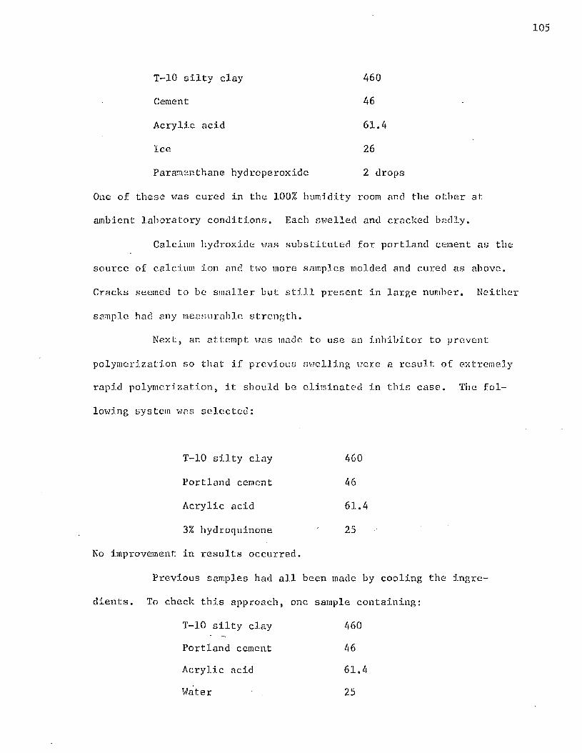
105
T-10 silty clay 460
Cement 46
Acrylic acid 61.4
Ice 26
Paramenthane hydroperoxide 2 drops
One of these was cured in the 100% humidity room and the other at
ambient laboratory conditions. Each swelled and cracked badly.
Calcium hydroxide was substituted for portland cement as the
source of calcium ion and two more samples molded and cured as above.
Cracks seemed to be smaller but still present in large number. Neither
sample had any measurable strength.
Next, an attempt was made to use an inhibitor to prevent
polymerization so that if previous swelling were a result of extremely
rapid polymerization, it should be eliminated in this case. The fol
lowing system was selected:
T-10 silty clay 460
Portland cement 46
Acrylic acid 61.4
3% hydroquinone 25
No improvement in results occurred.
Previous samples had all been made by cooling the ingre
dients. To check this approach, one sample containing:
T-10 silty clay 460
Portland cement 46
Acrylic acid 61.4
Water 25

106
was molded and allowed to become very hot while mixing* The mixed-
dry solids were dumped all at once into the water and mixed rapidly.
Cracking was limited to one crack about 1/8 inch wide around the
middle of this sample.
A new theory of swelling was then proposed. It was
theorized that the organic acid must start to diffuse to the surface
and polymerization occurred as it traveled. This would have in
creased the polymer particle size and have made it attract acid
monomers in its vicinity. The motion of these large particles in the
system wonId have dislodged other particles from their closely packed
arrangement causing cracks to form. Upon contacting a calcium ion and
reacting, the acid vapor pressure would have been lowered and diffu
sion reduced.
If this theory were correct, then a sample very well mixed
before molding would not swell because the reaction between acid and
calcium ion would be essentially completed. A sample was mixed as
usual and then run twice, through a grinder with very lot-; clearance
between blades. The sample emerged in powder form. The powder was
then compacted at 750 psi as all other samples had been. The results
were that swelling had not been reduced but had occurred much more
uniformly throughout the sample than in previous samples. This sample
(D) is pictured along side of a standard soil-cement blank (A) in
Figure 34.
Another check on the proposed theory was run simultaneously.
A sample which had swelled and crumbled to pieces was dried, ground
in a mortar and pestle, wet, and remolded. Acid diffusion should have

Figure 34. Even Swelling in a Well Mixed Sample Containing Acrylic Acid
been completed and the remolded sample was not expected to swell. It
swelled only 0.1 cm in height and 0.03 cm in diameter and no visible
cracks appeared.
To see if the exotherm from delayed chemical reaction were
causing the difficulty, a sample of the following composition was
prepared:

108
T-14 light silty clay 600
Portland cement 60
Acrylic acid 80
Ice 52.1
Immediately after molding, a 1/8 inch diameter hole was drilled from
the end of the sample to its middle and a thermocouple inserted into
it. A temperature profile was recorded for 48 hours with no noticeable
temperature deviation over this period noted. No highly exothermic or
endothermic reactions wore present. Some swelling did occur.
Since those samples in which the temperatures was allowed to
rise during mixing had less swelling, the effect of heating was in
vestigated. A sample of the following composition was molded:
T-14 light silty clay 460
Portland cement 46
Acrylic acid 61.3
Water 25
Paramenthane hydroperoxide 2 drops
No attempt was made to cool the ingredients and the molded sample was
placed into a 75°C. oven. Only a few barely visible cracks appeared
on this sample.
The fact that heating reduced swelling appeared to indicate
that rapid polymerization was desirable. To achieve rapid polymeriza
tion, an active free radical redox initiator catalyst system was em
ployed. This sample was of the following composition:

T-14 soil 460
Portland cement 46
Acrylic acid 61.4
FeSO**7H20 0.37
K2S20s 0.55
Paramcnthane hydroperoxide 0.18
Water 40
The FeSO^ • 711^0 and K2S20g were added to the water. The acid was then
added and finally the paramenthane hydroperoxide (PM1JP) was added with
stirring. The dry-mixed solids were then poured into the liquid with
rapid stirring. After curing for one. week at ambient laboratory con
ditions, this sample had several cracks and was cracked completely in
half at its midsection.
A second "hot” catalyst system was investigated in the fol
lowing sample:
T-14 soil 460
Cement 46
Acrylic acid 61.4
Water 40
Ammonium persulfate 9.6
Sodium thiosulfate 9.6
It was noticed that some liquid seeped out while the sample was undertP
pressure. After one week at ambient laboratory conditions, this sam
ple was only slightly less cracked than the previous one.
Previous experience indicated that samples always cracked
when excess liquid was present. Two more samples were molded using
less water. They were of the following composition:

110
T-14 soil 460 T-14 soil 460
Cement 46 Cement 46
Acrylic acid 61.4 Acrylic acid 61.4
Water 25 FeSO^*7H20 0.37
Ammonium persulfate 9.58 K2S208 0.55
Sodium tliiosulfate 9.58 Paramenthane hydroperoxide 25
Water 0.18
Each of these was cured in a G0°C. oven. Although some cracking
occurred, these two samples wore the best made up to that time.
The system selected for further study was the hydroperoxide-
containing system. Samples for a moisture-density curve were made by
varying the amount of water in the system. The most dense of these
contained only three grams of water and still appeared on the wet side
of the moisture-density curve. For further work, the acid-to-ceraent
equivalent ratio was held constant at 1:1 as acid and cement content
were varied. Three grams of water was maintained to dissolve the
FeSO^-ll^O and l ^ ^ O g . '^ie resulting moisture-density curve appears
in Figure 35 and the accompanying data are tabulated in Table XXVI.
Four samples of the composition indicated by the maximum in
the moisture-density curve were made. Each was wrapped in aluminum
foil to prevent monomer evaporation. Two of the samples were placed
directly in the 100% humidity room and two were first placed in a 60°C.
oven for 48 hours and then placed in the humidity room. On the twenty-
eighth day after molding, all four of the samples were submerged: in
water. After 48 hours under water, the two which had been in the oven
for two days before being placed in the 100% humidity room were par-;

122
121
120Dry
Density, lb. /c.u. f t
119
118
117
Molding Liquid Content, %
Figure 35. Moisture-Density Relation for Samples Containing Equal Equivalents of Acrylic Acid and Cement

112
TABLE XXVIMOISTURE-DENSITY DATA FOR ACRYLIC ACID SAMPLES
Composition of Samples
Weight % of Grams Total Solids
Soil (T-10) A60 90.74
Portland Cement 46 9.08
Acrylic Acid 61.4 —
FeS0/(-7H20 0.37 0.07
K 2S208 0.55 00.11
Paramcnthane Hydroperoxide 0.60 —
Water 3.0
Procedure
The acid-to-cement equivalent ratio was held constant in these samples. As acid increased, cement was increased proportionally. The composition shown above correspond;; to the maximum in the curve.
Data
Sample Molding Liquid Content, Dry DensityNumber gms./lOO grams solids lb./cu.;
5-105-1 8.8 117.0
5-104-2 10.8 119.9
5-105-2 12.8 121.8
5-105-3 14.7 118.9
5-106-1 16.7 117.1

tially disintegrated but still standing.. The other tvzo samples were
completely destroyed.
Four more samples identical in composition to the previous
four were molded, wrapped in aluminum foil, and placed in a cobalt
irradiation pit of approximately 10,000 curies strength for two days.
(See Appendix B.) After removal from the cobalt pit, two of the sain
pies were cured for 23 days in the 100% humidity room and two cured
at ambient laboratory conditions for 23 days. At the end of the cure
period, the samples in the humidity room had swelled and cracked the
aluminum foil at their mid-sections and had elongated 0.4 cm, each.
The two samples cured at ambient conditions were unaltered. All four
samples were then placed in a 60°C, oven for 48 hours before strength
tests were run.
Compressive strength and modulus data were meaningful only
on the uncracked dry cured samples. These data are presented in
Figure 36 and the accompanying Table XXVII. For comparative purposes,
curves for 28 day wet and 28 day wet-dry soil-cement are also pre
sented. Although the curing conditions of these samples were not
identical, the data presented give some indication of the modulus and
strength of the acrylic acid samples in relation to standard fully-
cured soil-cement. The average strength of the two samples on which
strength tests were run was 2060 psi. For comparison, the average
28 day wet strength of the standard soil-cement samples was 1473 psi
and the average 28 day wet-dry strength was 1637 psi. The highest
modulus attained in the acrylic acid samples averaged 0.241 x 10^ psi
for the two samples. The same averaged moduli for the 28 day wet and

114
2400
2000
Stress
1200
o c j :
- £tifQ Acrylic acid samplesA 28 day wet soil-cement © 28 day dry soil-cement
2.0Strain, Inches x 10
Figure 36. Modulus Curves of Samples Containing Acrylic Acid and of Fully Cured Soil-Cement

1X5
TABLE XXVIIMODULUS DATA FOR SAMPLES CONTAINING ACRYLIC ACID
Composition of Samples
Soil (T—10)
Weight % of Grams Total Solids
A 60Portland Cement 46Acrylic Acid 61.4FeS0^*7H20 0.37K2S208 0.55Paramenthane Hydroperoxide 0.6Hater 3.0
Data
Applied Stress, Strain(Psi) (Hundredths of an Inch)
Sample: 5-111-3 5-111-4
0 0.00 00.00125 0.28 0.38251 0.56 0.76377 0.89 1.04502 1.10 1.28628 1.32 1.40703 1.50 1.59880 1.70 1.781005 1.90 1.971130 2,10 2.121256 2.30 2.321381 2.50 2.511510 2.74 2.681633 2.94 2.911760 3.24 3.161886 3.49 3.402010 3.91 3.942110 4.62

28 day wet-dry standard soil-cement samples were 0.358 x 10^ and
0.194 x 10⁶ psi, respectively.
A series of small samples containing acrylic acid and
cement were made specifically for moisture absorption studies. All
solid components were dry-mixed by shaking and liquid components
mixed by stirring. The liquids were placed in a 250 ml. glass
beaker and the beaker placed in an ice-water slush. Crushed dry ice
was added to both solids and liquids to cool them before mixing. The
dry, cooled solids were then added slowly to the cold liquid with
stirring. Crushed dry ice v/as added as heat was generated. When
solid addition was complete, the moist mixture was packed into an
aluminum pan about 1/2 inch deep and 1-1/2 inches in diameter and
placed in a 110°C. oven for 4 hours. Samples wore allowed to coo],
slowly to room temperature before being submerged in water. Samples
were made with a fixed acrylic acid content and the ratio of cement
to acrylic acid was varied by varying the port]and cement content.
All acrylic acid used had the inhibitor removed by passing it over
activated alumina. The composition of the samples was as follows:
T-10 silty clay 50 grams
Portland cement Variable
Urea 3
Acrylic acid 12,5
Water 12.5
Paramenthane hydroperoxide 6 drops

The moisture absorption data for 30 minute, 7 day and 14 day
soaking periods are presented in Figures 37, 38, and 39 and accompany
ing Tables XXVIII, XXIX, and XXX. These data indicate that there is a
definite dependence of moisture absorbed by a sample on the equivalent
ratio of cement to acid contained in it. Minimum absorption occurs
when the equivalent ratio of cement to acid is slightly greater than
1.10. Samples with a cement-to-acid ratio less than 1.00 absorb mois
ture rapidly and after seven days must be handled carefully to keep
them from falling apart. After fourteen days under water, these sam
ples could no longer be weighed.
To investigate the effect of calcium ion source on moisture
absorption properties, a similar series of samples was made in which
the portland cement was replaced by calcium hydroxide. All experi
mental procedures were identical. The results of 30 minute., seven day,
and fourteen day moisture absorption measurements are presented in
graphical form in Figures 40-42 and in tabular form in Tables XXXI-
XXXIII, It should be pointed out that these data cover a much larger
range of cement-to-acid ratios thaxi the data for the cement system.
The absorption characteristics of samples containing calcium
hydroxide differ from those containing cement. Samples containing
slightly less calcium hydroxide than an equivalent amount of acid dis
integrate within thirty minutes. However, as the calcium ion content
is lowered further, absorption rate is decreased,■ The total eventual
absorption is unchanged because after seven days, all samples with a
calcium hydroxide-to-acid ratio of less than 1.0 are disintegrated.

Curve positioned by linear regression analysis
R2 » 0.8312
10
Thirty Minute
Moisture Gain,
.0 1.1 1.2Equivalents of Cement Equivalents of Acid
Figure 37. Moisture Absorption vs. Cement/Acrylic Acid Ratio at Constant Acid Content

119
TABLE XXVIIIMOISTURE ABSORPTION DATA FOR FIGURE 37
Composition of Samples
Weight % ofGrams Total Solids
Soil (T-10) 50 82.0 to 75.8
Portland Cement (8 — -13) 13.1 to 19.7.
Urea 3 4.9 to 4.5
Acrylic Acid 12.5 —
Paramenthane Hydroperoxide 0.6 —
Water 12.5 —
Data
Sample Equiv. Cement 30 Min. Sample Equiv. Cement 30 Min.Number Equiv. Acid Gain, % Number Equiv. Acid Gain, %
30-83-2 0.852 9.59 30-89-4 1.146 1.5530-88-5 0.852 10.21 30-100-7 1.173 1.8230-99-1 0.875 7.89 30-86-7 1.227 2.3930-83-3 0.922 4.46 30-101-1 1.280 2.3830-83-4 0.973 3.14 30-82-3 1.280 3.8030-86-2 0.987 1.90 30-89-5 1.333 3.1030-86-3 1.014 3.20 30-88-6 1.333 2.2230-1.00-5 1.014 2.12 30-101-2 1.333 2.3230-86-4 1.049 1.46 30-89-6 1.360 5.4530-100-6 1.089 2.06 30.101-3 1.377 4.9930-100-1 1.117 1.38 30-88-7 1.388 8.0430-100-2 1.117 1.80 30-83-1 1.388 7.9130-100-3 1.146 2.90

120
Seven Day
Moisture Gain,%
24Solid curve positioned by linear regression analysis
22
20
18
16
14
12
0.9 1.0 1.1 1.2 1.3Equivalents of Cement Equivalents of Acid
Figure 38. Seven Day Moisture Absorption vs. Cement/Acrylic Acid Ratio at Constant Acid Content

121
TABLE XXIX MOISTURE ABSORPTION DATA FOR FIGURE 38
Compos11ion of Samples
Soil (T-10)
Portland Cement
Urea
Acrylic Acid
Paramenthane Hydroperoxide
Water
Grams
50.0
(8 — >-13)
3.0
12.5
0.612.5
Weight % of Total Solids
82.0 to 75.8
13.1 to 19.7
4.9 to 4.5
Data
SampleNumber
Eciniv. Cement 7 Day Gain, %
SampleNumber
Equiv. Cement 7 Day Gain, %Equiv. Acid Equiv. Acid
3— 83-2. 0.852 Fell 30-100-1 1.117 12.630-88-5 0.852 Apart 30-100-2 1.117 13.530-99-1 0.875 11 30-100-3 1.146 15.030-83-3 0.922 T! 30-89-4 1.146 14.55-41-1 0.451 11 30-100-7 1.173 14.05-41-2 0.951 11 30-86-7 1.227 15.330-83-4 0.973 17.3 30-82-3 1.280 15.130-86-2 0.987 17.1 30-101-1 1.280 13.630-86-3 1.014 21.5 30-88-6 1.333 14.130-100-5 1.014 20-6 30-101-2 1.333 15.65-41-3 1.026 24.1 30-89-6 1.360 19.75-41-4 1.026 23.2 30-101-3 1.377 18.730-86-4 1.049 12.7 30-88-7 1.388 19.930-100-6 1.089 14.4 30-83-1 1.388 17.7

122
24
22
20Fourteen
Day Moisture
Gain,%
16
14
G Q
Solid curve positioned byregression analysxsline
0.18
18 —- -
Equivalents of Cement Equivalents of Acid
Figure 39. Fourteen Day Moisture Absorption vs. Cement/AcrylicAcid Ratio at Constant Acid Content

TABLE XXXMOISTURE ABSORPTION DATA FOR FIGURE 39
Composition of Samples
Soil (T-10)
Portland Cement
Urea
Acrylic Acid
Paramenthane Hydroperoxide
Water
Grams
50
(8 — >13)
3
12.5
0.6
12.5
Data
SampleNumber
30-86-230-100-530-86-330-86-430-100-630-100-130-100-230-89-430-100-330-100-730-86-730-101-130-89-530-88-630-101-230-100-430-89-630-88-730-101-3
Equiv. Cement Equiv. Acid
0.9871.0141.014 1.049 1.090 1.121 1.121 1.146 1.148 1.174 1.227 1.2811.3331.3331.333 1.336 1.3601.3801.380
Weight % of Total Solids
82.0 to 75.8
13.1 to 19.7
4.9 to 4.5
14 Day Gain, %
19.523.523.515.518.617.417.918.518.918.718.017.517.616.818.317.120.420.419.9

124
Thirty Minute
Moisture Gain ,
%
40 For ratio 1.0 to 3.0 curve positioned by linear regression analysi
35
30
25
20
15
10
5
0 3.00 1.0 2.0
Equivalents of Ca(0H)2 Equivalents of Acid
Figure 40. Thirty-Minute Moisture Absorption vs. Ca(OH)2 /AcrylicAcid Ratio at Constant Acid Content

125
TABLE XXXIMOISTURE ABSORPTION DATA FOR FIGURE 40
Composition of Samples
Weight % ofGrams Total Solids
Soil (T-10) 50 90.7 to 69.3
Calcium Hydroxide (2.1 — 19. 2) 3.9 to 26.6
Urea 3 5.4 to 4.1
Acrylic Acid 12.5 —
Paramenthane Hydroperoxide 0.6 —
Water 12.5 —
Data
Sample Equiv. Ca(OlI)^ 30 Min Sample Equiv. CafOlOo 30 Min.Number Equiv. Acid Gain, % Number Equiv. Acid Gain,%
30-31-9 0.332 9.7 30-31-1 1.100 10.030-31-8 0.501 13.3 30-31-2 1.200 14.730-103-2 0.577 * 30-90-1 1.310 12.25-41-5 0.601 28.9 30-90-2 1.463 12.430-31-7 0.668 20.3 30-104-1 1.463 9.330-31-6 0.770 29.1 30-18-2 1.557 18.95-41-6 0.803 * 5.62-3 1.610 13.030-31-5 0.833 33.3 30-89-1 1.868 16.630-103-1 0.833 * 30.89-2 2.180 17.730-31-4 0.911 27.4 30-89-3 2.650 16.15-62-1 0.951 14.1 5-62-4 2.710 9.130-30-1 1.000 4.4 30-31-3 2.990 13.95-62-2 1.000 8.2
* This sample absorbed so much water that it fell apart andcould not be weighed.

126
Seven.Day
MoistureGain,%
30
25
20
15O 0
10
5Solid curve positioned by linear regression analysis
R2 = 0.33
00 3.01.0 2.0
Equivalents of Ca(0H)2 Equivalents of Acid
Figure 41. Seven Day Moisture Absorption vs, Ca(OH)2 /AcrylicAcid Ratio at Constant Acid Content

127
MOISTURETABLE XXXII
ABSORPTION DATA FOR FIGURE 41
Composition of Samples
Weight % ofGrams Total Solids
Soil (T-10) 50 90.7 to 69.3
Calcium Hydroxide (2.1- * 1 9 . 2) 3.9 to 26.6
Urea 3 5.4 to 4.1
Acrylic Acid 12.5 —
Paramenthane Hydroperoxide 0.6 —
Water 12.5 —
Data
Sample Equiv. Ca(01I)9Number Equiv. Acid 7 Day Gain, %
5-62-1 0,95 27.45-62-2 1.00 18.030-30-1 1.00 16.530-31-1 1.10 16.730-31-2 1.20 17.830-90-1 1.31 14.830-90-2 1.46 14.130-104-1 1.46 18.530-18-2 1.56 21.45-62-3 1.60 14.130-89-1 1.87 19.630-89-2 2.18 20.430-89-3 2.65 18.15-62-4 2.71 6.730-31-3 2.98 11.5

128
Fourteen Day
Moisture Gain,%
30
23
20
15
10
5Solid curve positioned by linear regression analysis
R2 = 0.32
03.02.00 1.0
Equivalents of Ca(011)2 Equivalents of Acid
Figure 42. Fourteen Day Moisture Absorption vs. CaCOH^/AcrylioAcid Ratio

TABLE XXXIIIMOISTURE ABSORPTION DATA FOR FIGURE 42
Composition of Samples
Grams
Soil (T-10)
Calcium Hydroxide
Urea
Acrylic Acid
Paramenthane Hydroperoxide
Water
50
(2.1— ► 19.2)
3
Data
12.5
0.6
12.5
Weight % of Total Solids
90.7 to 69.3
3.9 to 26.6
5.4 to 4.1
Sample Equiv. Ca(OU)o 14 Day Gain,Number Equiv. Acid %
30-31-9 0.332 Samples30-31-8 0.501 Disintegrated30-31-7 0.668 M
30-31-6 0.770 T1
30-31-5 0.832 I t
30-31-4 0.911 I f
30-30-1 1.00 19.630-31-1 1.10 17.030-31-2 1.20 19.630-90-1 1.31 15.430-90-2 1.46 15.230-18-2 1.55 24.230-89-1 1.87 20.430-89-2 2.18 21.030-89-3 2.65 18.430-31-3 2.99 13.6

130
In contrast to the portland cement-containing system, the system con
taining calcium hydroxide gains very little moisture between the
seventh and fourteenth clays.
Preparation and Reaction of Tobermorite
The reaction of portland cement with acrylic acid is highly
exothermic. This exotherm caused spontaneous polymerization of the
acrylic acid and for this reason dry ice was used to cool the reactants
in previously described work. Spontaneous polymerization was undesir
able because it froze the system in a poly (acrylic acid) network be
fore the pendant carboxyl groups could react with the calcium ions
present. This neutralization reaction was required to insolubilize
the polymer.
In the theory section of tliis dissertation it was explained
that the desired structure was one composed of interwoven polymer and
cement hydration matrices. However, the highly exothermic reaction
which occurred immediately upon contact of cement and acid raised some
question as to whether the cement would hydrate normally in the pres
ence of acrylic acid. X-ray diffraction techniques were used to study
this reaction. As the calcium in the cement hydration lattice was
chemically bonded to the polymer (forming an ionomer) a change in the
crystal structure of the hydrated cement would be expected. It would
appear to be a simple matter to mold two samples, one containing
acrylic acid and one a standard blank, run their x-ray diffraction pat
terns, and determine any change in structure from these patterns. How
ever, Bc.gue(1) has stated that:

131
"Under the most favorable conditions, quantities of material less than 2 or 3 per cent of the total can rarely be identified. For the detection of such small amounts of material, the crystals should be well developed, possess a high order of symmetry and a simple structure, and give rise to lines which do not coincide with those of the patterns of other materials present."
Since the portland cement in the soil-cement system studied constituted
only about 9% of the material present, and since tobermorite consti
tutes only about half of the total hydration products of cement,
changes in tobermorite crystal structure would be difficult to detect
under the most favorable conditions.
For these reasons, an alternate approach was taken. A pure
material of similar crystal structure and chemical composition
(5Ca0*5Si02*H20) was prepared in a pressure autoclave as recommended
by Kalousek in U.S. Patent 2,547,127 (see Appendix C for details of
autoclave). The reaction product is also commonly referred to as
tobermorite. Since no soil was present to mask the diffraction pat
tern, and since tobermorite now constituted 100% of the crystalline
material present, its x-ray diffraction patterns could be studied
easily. X-ray diffractograms of pure tobermorite and of tobermorite
and acrylic acid thirty minutes after mixing are presented in Figure
43. It is obvious from these data that the crystal structure of tober
morite is drastically changed in the presence of acrylic acid. In
Figure 44 the diffractogram of a tobermorite and acrylic acid mixture
30 minutes-after being mixed is compared with the diffractogram of the
same mixture 24 days after being mixed. These data indicate thae new
crystalline reaction products are present after 24 days.

TOBERMORITE
TOBERMORITE + ACRYLIC ACID
s13 102030 25DEGREES - 20
FIGURE 43. X-RAY DIFFRACTOGRAMS OF TOBERMORITE AND FRESHLY MIXED TOBERMORITE AND ACRYLIC ACID

2 4 DAY
3 0 MINUTE
0E6REES - 29 30 2025
FIGURE 4 4 . X-RAY DIFFRACTOGRAMS OF TOBERMORITE - ACRYLIC ACID MIXTURE AFTER DIFFERENT CURE PERIODS

134
REFERENCES
1. Bogue, Robert Herman, The Chemistry of Portland Cement, Hew York: Reinhold Publishing Corporation, 1955. 572 pp.

135
DISCUSSION OF RESULTS
Space Polymers in Soll-Cement
Since soil-cement develops strength as the cement hydrates by
taking up water, and urea-formaldehyde resin polymerizes by loss of
water, one might expect that a system'composed of the two would be ideal.
However, it was found that one week after being nixed, a sample contain
ing only soil, cement, and urea-formaldehyde had not hardened. This
indicated that the cement had not hydrated properly nor had the resin
polymerized into a space polymer. Under the alkaline conditions exist
ing in a cement environment the rate of polymerization of urea-formal
dehyde appears to be slowed to the extent that no hardening is detect
able after one week. With such a low polymerization rate the formation
of water from the condensation reaction is slow and therefore the cement
does not have available the water it needs for hydration. It is also
probable that the carbonyl oxygen, with its unshared electrons, that is
present in the urea is attracted by the cement cation and attempts to
serve in a hydration network as does the oxygen atom in water of hydra
tion. This attraction of polymer to cement would coat the individual
cement particles with unpolymerized urea-formaldehyde resin, holding
individual cement particles apart and destroying the normal hydration
reaction.
Samples of similar composition to the above, except that
phenol-formaldehyde replaced urea-formaldehyde, were found to be stronger
than those containing urea-formaldehyde, but lost most of their strength
when wet. The improved dry strength of the phenolic samples can be

explained in two ways. No experiments were performed to differentiate
between these and it is likely that each actually contributes to
strength. The phenol-formaldehyde system would be expected to be
stronger than a urea-formaldehyde system since the phenolic resin used
is often polymerized under alkaline conditions. The alkaline cement
environment should have increased the polymerization rate rather than
reduced it as in the urea system. However, this may not be the only
reason for a stronger sample since on a statistical basis, there should
be less electrostatic interference upon cement hydration by electro
negative atoms in the phenol-formaldehyde system, and any increase in
cement hydration would increase strength.
Based upon the above experimental results and upon theoretical
considerations to be presented, no further experimental work was done
using space polymers. One of the existing weaknesses in soil-cement is
the brittleness of the cement hydration lattice. All space polymers,
because their molecules are locked rigidly in position, are brittle.
Even though two interwoven lattices form, no substantial strength im-
pi'ovement would be realized because neither lattice could distribute
any appreciable amount of its load to the other. If a polmer of lower
elastic modulus were added, a distribution of force could be realized,
reducing the load carried by an individual member and substantially
strengthening the system.
Nonpolymeric Carboxylic Acid Molecules
Reproducibility of Results in Ct r.pression Testing
Because nonpolymeric carboxylic acid molecules are the first
samples discussed that were molded using the equipment described in the

137
introduction, the reproducibility of results using this equipment is
discussed here. In order to get unconfined compressive strength data
to fall within + 5% of its average value on identical samples, certain
procedures must be followed. Samples must be well mixed and molded at,
or very near, optimum moisture content. One unaccustomed to molding
usually adds excess moisture. It was found that all samples containing
more than approximately 3% excess moisture cracked when being removed
from the molding cylinder. Mold release compounds used to allow samples
to slide from the cylinder without cracking did not prevent cracking and
also affected moisture absorption properties. At optimum moisture a
lubricant is not needed to prevent cracking. Pistons must be clean
when inserted since if small quantities of soil are allowed to remain
between a piston and the cylinder, the piston will stick in the cylinder.
All samples must be compression tested at the same rate. Increasing the
compression rate increases the measured strength of a sample. Strength
data on samples used to determine optimum density are not comparable with
other data because these samples are dried at 110°C which chemically af-
fects the soil. Soil used for normal testing should not be dried at
temperatures exceeding 140°F.
Oxalic Acid and Calcium Oxalate Samples
From Figure 14 it can be seen that at optimum moisture content
the maximum density of samples containing oxalic acid is 109.3 lbs./cu.ft.
This is lower than the maximum density of standard soil-cement by 3.1
lbs./cu.ft. It seems reasonable to assume that since oxalic acid is
added in solution and since it reacts with the cement to form insoluble
calcium oxalate, the molded sample would be more dense due re the

138
presence of the calcium oxalate after the free water has evaporated. It
is obvious that this is not the result. The oxalic acid or calcium
oxalate In some way evidently causes the cement lattice to expand. In
this case it is felt that a chemical complex is developed between the
Portland cement and the carbonyl oxygen in the acid. However, as time
passes, the cement prefers to substitute the oxygen atom in a water
molecule for the carbonyl oxygen in the acid. This substitution evi
dently is accompanied by an increase in volume which weakens any rigid
hydration lattice present. This is in agreement with the strength data
in Table VI where it can he seen that even after twenty-eight days in
the 100% humidity room, samples containing oxalic acid had little
strength. In any event It is evident that a cement to acid bridge and
a cement lattice which would strengthen the system does not form. The
acid may extract the calcium from the cement entirely and thereby stop
the hydration reaction.
The data on samples to which calcium oxalate was added agree
with the proposed theory of oxygen exchange. The carbonyl oxygen in
calcium oxalate is less electronegative than the carbonyl oxygen in
oxalic acid because the large positively charged cation has the ability
to withdraw electrons. The large size of a calcium ion as compared to
a hydrogen ion also increases steric shielding. Each of these conditions
would reduce the participation of a carbonyl oxygen in the cement hydra
tion lattice and therefore strengthen the system. Although the data on
calcium oxalate-containing samples is not conclusive, it appears to
support these ideas.

139
Terephthalic Acid Samples
From Figure 15 it can be seen that the maximum density reached
in samples containing terephthalic acid in equal equivalents with the
cement present was 104,6 lbs./cu.ft,, 7.8 lbs./cu.ft. less than standard
soil-cement. This behavior would be expected since terephthalic acid is
not appreciably water soluble and has a specific gravity of about 1.6
as compared to 2.73 and 3.1 for T-10 silty clay and cement respectively.
The data in Table VII indicate that the presence of tere
phthalic in a soil-cement sample cured in the 100% humidity room inter
feres extensivley with cement hydration. Even after twenty-eight days
in 100% humidity the samples will support only about 200 psi compared
to about 1450 psi for standard soil-cement under 28 day wet conditions.
Coupled with this was the appreciable swelling of all samples cured in
the humidity chamber. It appears that here too the acid adversely af
fects the cement hydration reaction either by the carbonyl oxygen influ
ence or by complete calcium extraction. This system differs from those
discussed earlier in that the presence of the aromatic ring makes the
acid phase hydrophobic which can lead to a phase separation. If the
sample were well mixed, a phase separation could account for the even
swelling observed. The presence of moisture is necessary for swelling
to occur because it provides the necessary particle mobility. ■ Without
mobility, static forces between particles apparently are not of suffi
cient strength to relieve themselves by particle motion. This is pointed
out in the increased strength of the sample cured under 28 day ambient
conditions. No swelling was observed in this sample.

140
Cyclopentanetetracarboxylic Acid Samples
The only unusual feature of these samples was their method of
cracking. (See Figure 17.) Instead of swelling evenly as the tere
phthalic acid-containing samples, these cracked extensively and large
sections sluffed away from the body of the samples. This could have
resulted from the polyfunctionality of CPTA samples. Each CPTA molecule
has the possibility of being attacked chemically to four calcium con
taining particles. If this attachment were by carbonyl oxygen hydration
and one of the carbonyl oxygens were then forced from its site in the
hydration lattice by a water molecule, a strained system would result.
Forcing one member of a relatively rigid ring to move would tend to cause
motion in the other members. In effect, it 'would be acting as a space
polymer. It therefore seems reasonable that in such a system internal
stresses could build up in such a fashion that relief has to be obtained
through relatively large movement of the soil-cement. This would account
for the large cracks observed in these samples.
Polymeric Carboxylic Acid Ionomers
The maximum density obtained in soil-cement modified with
sodium carboxymethyl cellulose (Na-CMC) was 112.1 lbs./cu.ft. Since this
is within 0.3 lb./cu.ft. of standard soil-cement, it is evident that at
the concentration used (0.41 weight %) the Na-CMC has no beneficial ef
fect as a surfactant. If the small difference noted in density is re
producible, the reduction in density could be explained by the light
weight of the polymer.
The data presented in Figure 19 and also in Table XI reveal
some interesting facts about the behavior of Na-CMC modified soil-cement.

The fact that 28 day strengths are higher than 7 day strengths indicates
that in this system the portland cement is partially hydrating and con
tributing to strength development. This hydration probably occurs be
cause the exchange reaction between calcium and sodium is slow enough to
allow some of the cement to hydrate before the reaction is complete. Of
course, as points along the polymer chain become fixed by attachment to
an immobile calcium ion, the polymer chain mobility decreases and further
reaction is slowed. The fact that wet strengths were lower than wet-dry
strengths indicates that the ionomer formed is water sensitive. Since
increasing the molecular weight of the polymer increased the strength of
samples, the polymer must also be contributing to composite strength. If
the polymer were contributing nothing to the system, then a change of
molecular weight in the polymer would not noticeably alter the final
strength of the test speciman.
Five series of samples were molded and cured under the five
standard cure conditions chosen for this research. Each series was to
determine the effect of the pH of the Na-CMC solution used as the molding
liquid on the compressive strength of the samples. The results were pre
sented in Figures 20-24 and Tables XII-XVI. The curves drawn through
these sets of data were the best fitting second order curves as calcu
lated by multiple linear regression. The statistical curve for seven day
wet strength (Figure 20) indicates that samples molded with a Na-CMC
solution of pH 8 to 9 give maximum strength. The reduced strength at low
pH could indicate that the increased acidity causes more harmful effects
on the cement than beneficial effects that may be obtained by replacing
the sodium ion with a hydrogen jcn on the polymer. Theoretically, the

142
polymer should give higher strengths if most of the pendant carboxyl
groups were in the acid form as opposed to the salt. The acid form
should react rapidly with any calcium ion present producing the in
soluble calcium ionomer. The reduced strength at high pH could indicate
that the beneficial effect of high pH on the cement hydration was out
weighed by the harmful effect of replacing all the hydrogen ions with
sodium ions on the pendant carboxyl groups. However, it is felt that
these data alone are insufficient to yield any firm conclusions but that
the pH of the Na-CMC solution appears to have little effect on the com
pressive strength of molded cylinders. The shape of the curve drawn
through the data is controlled to a large degree by the end points. Ift
the three data points at a pH of 0.8 were omitted from the analysis, a
straight line would fit the data reasonably well.
The second scries of Na-CMC samples cured under seven day
wet-dry conditions is presented in Figure 21 and Table XIII. The most
notable differences between these and the proceeding data are that seven
day wet-dry strengths are on the average 500 psi higher than seven day
wet strengths and that the statistical curve has changed from convex to
concave. The first of these is in agreement with data presented in
Figure 19 and discussed earlier. The second is most likely the result
of forcing the data to fit a second order statistical curve since the2fit of the curve as indicated by the R value is quite poor. It should
be noted that the data from wet-dry strength tests are considerably more
scattered than data from wet strength tests.
Data presented in Figure 22 and Table XIV are for samples
identical to those presented in Figure 20 and Table XII except that the

143
compression molding cylinders were cured under 28 day wet conditions as
opposed to 7 day wet conditions. In comparing the two sets of data, it
is again noticed that a transformation from convex to concave has oc
curred in the statistical curve. However, the few scattered data taken'
make any weighted curve which includes these points subject to question.
Before real meaning can be applied to this change, more data would cer
tainly have to be taken. One can conclude from the data, that there is
an increase in strength from approximately 650 psi at seven days to
approximately 750 psi at 28 days.
Comparison of 28 day wet-dry strengths (Figure 23 and Table XV)
with 7 day wet-dry strengths (Figure 21 and Table. XXIX) reveals an in
crease of approximately 250 psi with prolonged curing. Because of scat
ter in the data, no further conclusions can be drawn from the strength
data on 28 day wet-dry samples.
Unconfined compressive strength data for molding cylinders
cured under 28 day ambient conditions are presented in Figure 24 and
Table XVI. These data indicate that cylinders cured at ambient labora
tory conditions are approximately 900 psi stonger than any others in
this series. It is felt that this is solely due to the effect of re
moval of moisture from the sample before testing. Removal of moisture
increases the measured strength of cement-containing samples only
slightly but markedly increases the strength of samples containing Na-CMC
probably because of the water solubility of Na-CMC and the water sensi-I
tivity of the calcium salt of CMC.
It was noted in the experimental results sections of this
dissertation that samples containing 0.41 weight per cent Na-CMC of

144
molecular weight 200,000 had a lower modulus than samples containing
0.41 weight per cent Na-CMC of molecular weight 70,000.. This trend is
contrary to accepted polymer behavior where an increase in molecular
weight of the polymer generally causes an increase in elastic modulus.
However, in a polymer modified soil-cement, the polymer molecules are
homogeneously dispersed throughout the soil-cement network and polymer-
polymer cohesive forces are no longer the major forces controlling
specimen composite behavior. The controlling forces in a dispersed
system appear to be more dependent on primary bonds formed by neutrali
zation of the carboxyl group than on secondary Van der Waal's forces.
In this light it appears reasonable that a system containing the higher
molecular weight polymer would be more elastic because the polymer can
impart more of its elastic nature to the cement lattice. Points of at
tachment to the cement lattice can be farther apart, allowing more
elongation of the polymer molecules before reaching the ultimate yield
point.
Figure 26 indicates that polymer concentration has no effect
on modulus of elasticity but that increasing the concentration of Na-CMC
from 0.4 to 0.8 percent of the total solids increases the 28 day wet-dry
strength of the sample by 300 psi. These data may be somewhat mislead
ing because the water soluble Na-CMC must slow the cure rate of soil
cement since it reduces the vapor pressure (le. partial pressure) of the
water. These sample then may not be fully cured in 28 days. These
results are as expected since at these low polymer concentrations an
increase in polymer content allows the development of a more extensive
ionomer network. Samples cured under 28 day wet-dry conditions show

an increase in strength with an increase in polymer concentration indi
cating that under these test conditions the increased size of the poly
mer network is contributing more to strength than to further destruc
tion of the cement crystalline lattice. At low concentration the
presence of the polymer evidently contributes more to the disruption
of the hydration lattice than it does to strength generation from
ionomer formation. It could be postulated that a further increase in
polymer concentration would further improve strength and could possibly
produce strengths above those of standard soil-cement.
Moisture absorption data for cylinders molded with Na-CMC
solutions of different pH and cured under different conditions are
presented in Figures 30, 31, and 32 and Tables XXII, XXIII, and XXIV.
These data indicate that neither the pH of the Na-CMC solution added
nor the method or length of cure noticeably affect moisture absorption
characteristics. These data lead to the supposition that in these
samples, moisture absorption is controlled by the density of the molded
cylinder. The curve representing the data in Figure 31 was positioned
by eliminating the data points at pH = 4.4 because this sample was
badly damaged and appears to be inconsistent with the rest of the set.
Samples containing acidified carboxymethyl cellulose were low
in strength as expected. In the acidified form, CMC is insoluble and
therefore not easily dispersed throughout the system. Although added
in powdered form, the individual particles remained distinct. The low
strength of the samples is evidence that the acidity of the particles
interferred with cement hydration extensively.

146
Monomers Containing Pendant Carboxyl Groups
The data presented on acrylic acid systems have lead to some
rather surprising results. Conventional soil-cement theory has been
developed with the idea that maximum strength is developed in a soil-
cement system when just enough binder is present in the system to fill
the free volume and coat the surfaces of all particles so that they are
cemented together at all points of contact. Any excess binder weakens
the system by forcing particles apart which allows increased shearing
moments as load is applied. Experimental strength data on soil-cement
samples are in direct contradiction to this theory. When molded at
optimum moisture content (see Figure 35 and Table XXVI) acrylic-acid-
containing samples had a maximum density of 122.0 lbs./cu.ft. The 28
day strength of these samples when cured as described in the Experi
mental Results section of this dissertation was 2060 psi. This was
25.8 percent higher than 28 day \jet-dry strengths for standard soil-
cement. It must be pointed out that the strength of soil-cement in
creases as water is removed and that the soil-cement samples referred
to here were dried at ambient conditions for two days but were not
placed in the oven as were the acid-containing samples. By conven
tionally accepted soil-cement theory, any increase in acrylic acid
content would weaken the soil-cement test specimen. However, it was
observed that soil-cement cylinders containing a large excess of
acrylic acid, in fact, enough excess acrylic acid to cause the volume
of a test cylinder to increase by more than 40 percent, had a strength
of 3000 psi., 45 percent above that of the acrylic acid sample molded
at optimum moisture content. Calculations (see Appendix D.) have

147
shown that under the molding conditions employed, standa/.l soil-cement
contains 16.96% free volume when first molded. It would be logical to
assume that the noticeable strength improvement had resulted from fill
ing this free volume with polymer. However, similar calculations have
indicated that samples containing acrylic acid at optimum moisture con
tent have a free volume of 15.87%, only 1,09% less than standard soil-
cement. It seems unlikely that such a small reduction in free volume
could cause a strength increase of 20% or greater. It might next be
assumed that the high strength of the acrylic acid samples was due to
the fact that the cured samples were of higher density. This high den
sity (122.0 vs 112.4 for standard soil-cement) was a result of the
polymer occupying the free volume which is normally created in a stand
ard soil-cement sample when the water not required for hydration is
allowed to evaporate. If this were the complete answer, then any fur
ther increase in polymer content would have no strengthening effect
since no accessible free volume remains in a cured sample containing
acrylic acid at maximum density. It should be recalled, however, that
the data show that a considerable increase in polymer content caused
an increase in strength from 2060 psi. to 3000 psi.
As a direct result of these data, a new theory of strength
generation in polymer-modified soil-cement has been advanced. The in
creased strength of the soil-cement cylinders high in polymer content
appears to be due to the viscoelastic properties of the polymer. The
polymer separating the individual soil and cement particles is viscoe
lastic enough in behavior that it can undergo stress relaxation under
load.and distribute its stress evenly to the particles -beneath. This

148
even distribution of stress eliminates small points of stress concen
tration which characterize a brittle material and allow larger applied
loads before rupture occurs. The viscoelastic properties of the poly
meric binder cause the system to deviate from a true shear mode of
compressive failure dictating that new models for strength prediction
must be developed. In addition to enhanced compressive strength prop
erties, a system composed of a rigid lattice interwoven with and at
tached to a viscoelastic network should also exhibit improved tensile
strength, elongation, and toughness.
The stress-strain diagram of samples containing acrylic acid
is presented in Figure 36 and compared with those of 28 day wet and 28
day wet-dry standard soil-cement.
It might at first seem strange that the modulus of 28 day
wet soil-cement is higher than that of 28 day wet-dry soil-cement.
This has been explained by the fact that all accessible free volume in
the wet samples was filled with water, an incompressible fluid, which,
at a finite rate of load application, acts to increase the effective
modulus. The dry samples had air occupying all free volume which,
during load application, could deform leaving the hydration lattice to
support the entire load. At an infinitely slow rate of load applica
tion the two sets of curves should agree because the pore water in the
interior of the wet samples would have sufficient time to diffuse to
the outside. In this case the rate of load application and the rate of
diffusion would be comparable.
With these ideas in mind, it then seems reasonable that the
modulus of the acrylic acid samples would lie between these two

149
extremes, because the acrylic acid occupies essentially the same free
volume occupied by water in the wet sample, but poly (acrylic acid) is
more compressible than water. This would cause the acrylic acid sample
to have a lower modulus than the wet sample but a higher modulus than
the dry one.
The results of moisture absorption studies on small samples
containing different ratios of portland cement to acrylic acid are pre
sented in Figures 37, 38, and 39 and Tables XXVIII, XXIX, and XXX.
These data indicate a definite composition at which minimum absorption
occurs. This occurs when there is a slight excess of cement above that
required to react completely with the acid in the sample. It is felt
that this composition corresponds to that of calcium acrylate and that
excess cement is indicated because of imperfect mixing and therefore
incomplete reaction between the cement and acid.
After being immersed in water for 30 minutes all samples were
able to be removed and weighed. After being in water for 7 days, the
samples at low cement contents were so swollen that they were damaged
in handling. In Figure 38 these four samples are indicated as lying
above 24% absorption by having upward-pointing arrows on them. These
particular data also show a reverse slope to the dotted line indicated
in the figure. It was felt that this apparent reverse slope was gen
erated by the scatter in the data. The decomposition of the samples
low in cement content has been explained by the fact that poly (acrylic
acid) forms a gel when sufficient water is present. At cement contents
lower than the acid content, some acid cannot form the relatively in
soluble calcium salt, and therefore must exist as poly (acrylic acid).

150
It can be noticed from examining Figure 39 that after fourteen days in
water all samples containing a cement to acrylic acid ratio of less
than 0.98 had completely fallen apart. The upward slope of the right
hand portion of the curves is decreasing as time increases but still
may indicate that the presence of acid in the system reduces absorp
tion. As compositions approach the far right hand side they are ap
proaching the properties of pure cement. Even if the eventual total
absorption is not decreased, the formation of poly (calcium acrylate)
certainly slows the rate of moisture absorption by soil-cement.
Moisture absorption data on samples similar to the above
except that calcium hydroxide was substituted for portland cement are
presented in Figures AO, 41, and 42, and Tables XXXI, XXXII, and
XXXIII. It should be pointed out that unlike the previous figures,
these cover an equivalent ratio range of approximately zero to three.
This extended range was possible because samples with high calcium ion
content could be mixed without setting. Samples with high cement con
tent could not be well mixed without setting prematurely. The curves
for calcium hydroxide samples are somewhat similar to the curves for
cement samples over the range covered by cement samples. However, the
extended range of the data on calcium hydroxide samples contributes
additional information. At low calcium ion content, the rate of mois
ture absorption again decreases. This is probably caused by the fact
that an increasing poly (acrylic acid) gel formation which reduces
moisture penetration at the sample surface initially reduces moisture
absorption. However, it can be seen from Figure 41 that after seven

151
days all samples containing fewer equivalents of calcium ion than acid
have completely fallen apart. These data also indicate that as a large
excess of calcium ion is added, the rate of absorption again decreases.
It is not immediately evident from these data whether this is a fault
of the statistical curve or a real phenomena. It should be observed
that although the samples containing portland cement absorbed about
four percent between the seventh and fourteenth days, the samples con
taining calcium hydroxide absorbed almost none at all, however the
total absorption at an equivalent ratio of 1.0 was about the same in
each case. These comparisons lead to the impression that the rates of
absorption are initially controlled by the anion accompanying the cal
cium ion and that the total eventual absorption is controlled by the
final calcium ionomer.
At the end of moisture absorption tests it was noticed that
samples relatively high in acid content could be kneaded by hand into
a very elastic modeling clay. This clay remained pliable as long as
it was submerged in water but hardened into a rather brittle solid when
dried.
The x-ray diffractograms presented in Figures 43 and 44 were
run to determine the effect of acrylic acid on tobermorite formed dur
ing the hydration of portland cement. From Figure 43 it is evident
that pure tobermorite undergoes a drastic crystalline alteration when
mixed with acrylic acid. The characteristic peaks at 8 , 29, and 30
degrees are all eliminated. This ii = 31 cates that even if acrylic acid
did not interfere with tobermorite formation, it would immediately
react with the tobermorite formed. However, it appears from strength

data that this alteration in crystal structure does not necessarily
cause a decrease in strength. From Figure 44 it can be seen that if
the acrylic acid and pure tobermorite are left in contact for twenty-
four days a new crystalline product develops. Wo attempt was made to
determine the exact composition of the newly formed crystalline mate
rial.
These data indicate that a careful study into the reaction
between portland cement and acrylic acid would be necessary before the
exact contribution of either to the composite strength of a modified
soil-cement system could be determined.

CONCLUSIONS
The unconfined compressive strength of soil-cement samples contain
ing poly (acrylic acid) is higher than standard soil-cement for
three reasons:
a. polymer exhibiting viscoelastic properties occupies the free volume normally created when water not required for hydration evaporates from the system
b. the polymer-modified system is more dense than standard soil-cement
c. a stronger binder has been introduced into the system.
Maximum strength is not reached at maximum density in an acylic acid
modified soil-cement. In fact, maximum density curves appear to
have little value in predicting the maximum strength that could be
obtained in such a system.
The Mohr-Coulomb theory of shear failure should not apply to poly
mer-modified soil-cement systems if the polymer can exhibit visco
elastic behavior since flow occurs within the matrix of a visco
elastic material to allow a uniform distribution of stress.
Under the molding conditions employed in this research, calculations
have shown that standard soil-cement samples retain about 17% free
volume as airspace when removed from the molding cylinder. Approxi
mately the same free volume is present in an acrylic acid modified
soil-cement. In the acid modified system, this free volume does not
change.

154
5. Swelling'can be reduced in slowly polymerized acrylic acid modified
soil-cement by substituting calcium hydroxide for portland cement.
This probably results from the greater mobility of the calcium ion
in calcium hydroxide as compared to the calcium ion in portland
cement.
6 . The formation of a putty-like insoluble modeling clay in wet sam
ples containing excess equivalents of acid in comparison with the
cement present, indicates that polymer formation did occur and that
insolubility was achieved.
7. Acrylic acid reacts with the tobermorite formed in cement hydration
and changes its crystalline structure as shown by x-ray diffraction.
8 . Addition of a polymeric carboxylic acid to soil-cement (Na-CMC)
caused no increase in density or strength.
9. Sodium and calcium ionomers are water sensitive and therefore sam
ples containing either of these ionomers have considerably more
strength when dry than wet.
10., The compressive strength of a polymer-modified soil-cement is a
function of the molecular weight of the polymer. Higher molecular
weight polymers give higher strengths.
11. Data taken in this research indicate that the modulus of a polymer-
modified soil-cement is a function of the molecular weight of the
polymer.

155
12. The pH of a solution of sodium carboxymethyl cellulose added to
samples appears to affect compressive strength, density, moisture
absorption, and modulus of elasticity of soil-cement only slightly.
13. The results of this research indicate that any polymers added
should be hydrophilic in character to prevent phase separation in
the system. Any phase separation tends to interfere with cement
hydration by exclusion of water.
14. At low concentrations, the concentration of polymer appears not to
affect the modulus of test cylinders. Modulus effects are impor
tant because a decrease in modulus can impart toughness and limited
flexibility to a soil-cement system.
15. At appears that the addition of simple molecular carboxylic acids
increases neither strength nor density of soil-cement. This may be
due to the interference of the carbonyl oxygen in hydration or to
the acid effect on the cement.
16. The addition of a space polymer to a soil-cement system is not
recommended for maximum strength. Both the space polymer and the
cement hydration lattice form immobile and rigid networks. Such
systems do not normally undergo relaxation in order to distribute
load uniformly throughout the system.
17. Highly electronegative sites in a polymer, such as a carbonyl
oxygen, appear to interfere with cement hydration by taking rhe
place normally occupied by the oxygen atom from a water molecule.

156
For this reason,.a polymer with fewer highly electronegative sites
should interfere less with cement hydration and therefore result
in a stronger soil-cement system.
18. Experimental evidence indicates that a carbonyl oxygen atom par
ticipating in a hydration network can be forced out by a water
molecule and cause swelling to occur in a soil-cement sample dur
ing cure.
19. The participation of an electronegative carbonyl oxygen atom in a
cement hydration lattice can be reduced by partially cancelling■the
electronegative center. One way of doing this is by addition of a
metallic cation to the polymer in the vicinity of the carbonyl
group. This can be accomplished by converting a carboxylic acid
functional group into a salt.

RECOMMENDATIONS
To obtain the most improvement in physical properties of a soil-
cement in subsequent investigations, my recommendations are that:
a. a linear polymer, with limited crosslihking established to prevent irreversible flow of polymer molecules under stress and to limit moisture sensitivity, be used.
b. a polymer exhibiting viscoelastic behavoir be used so that stress can be evenly distributed.
c. the polymer be added in monomeric form,
d. the polymer be insoluble in polymeric form.
e. the polymer contain at least some functional group capable of chemical attachment to calcium ions in the system,
f. a monomer capable of polymerizing to high molecular weight be used.
g. the polymer be of high strength when pure.
h. the polymer be of lower modulus of elasticity than thecement hydration lattice, in fact it probably should be an elastomer rather than a crystalline polymer.
i. the polymer contain no highly electronegative centers capable of interfering with cement hydration.
j. the polymerization be easily controlled.
I would recommend that in systems containing portland cement, care
ful attention be paid to the effect the polymer has on the establish
ment of the cement hydration lattice.
Calculations have shown that a freshly molded standard soil-cement
cylinder contains approximately 17 percent free volume, presumably
because of air entrapment. The displacement of this air with poly
mer should strengthen the system. I would recommend that surface

158
active agents be sought which would reduce the interfacial tension
between solid and liquid phases thus allowing monomer to displace
as much of this air as possible.
4. I would also recommend that the curing time of samples containing
polymers which significantly reduce the partial pressure of water
in the sample be extended beyond 2.8 days thus allowing more time
for cement hydration. The reduced partial pressure of water must
surely lengthen the time required to reach 95% cure in the hydration
reaction.
5. To insure reproducible results and to eliminate density variation
with position in the molded cylinders, it is recommended that smal
ler compression test cylinders be molded. To insure reproducibility,
the length to diameter ratio of compression cylinders should be at
least 2 to 1 .

BIBLIOGRAPHY
Bear, Firman E. ed., Chemistry of the Soil, American Chemical Society Monograph Series, New York: Reinhold PublishingCorporation, 1964.
Bogue, Robert Herman, The Chemistry of Portland Cement. New York: Reinhold Publishing Corporation, 1955. 572 pp.
Brunauer, Stephen, and L. E. Copeland, "The Chemistry of Concrete Scientific American 210:81-91, April, 1964.
Demirel, T., and Donald T. Davidson, "Stabilization of a Calcareous Loess with Calcium Lignosulfonate and Aluminum Sulfate Proceedings of the Iowa Academy of Science 67:290-313, 1960.
Dunlap, Wayne A., Bob M. Gallaway, Edward C, Grubbs, and Joe E. House, "Recent Investigations on Use of a Fatty Quaternary Ammonium Chloride as a Soil Stabilizing Agent," Highway Research Board Bulletin 357:12-40, 1962.
Geist, Jacob M. , Servo V. Amagna, and Brian B. Mellor, "Improved Portland Cement Mortars with Polyvinyl Acetate Emulsions," Industrial and Engineering Chemistry 45:759-63, April, 1953.
Gnaedinger, Robert J., United States Patent 2,865,177, December 23, 1958.
Goldfein, S., "Plastic Fibrous Reinforcement for Portland Cement, U. S. Army Engineers, Research and Development Laboratories Technical Report 1757-TR, Fort Belvoir, Virginia
Gow, A. J., D. T. Davidson and J. B. Sheeler, "Relative Effects of Chlorides, Lignosulfonates and Molasses on Properties of a Soil-Aggregate Mix," Iowa Engineering Experiment Station, Iowa State University, Ames, Iowa.
Herzog, A., and J. K. Mitchell, "Reactions Accompanying Stabilize tion of Clay with Cement," Highway Research Record No. 36, 1963. pp. 146-71.
Laguros, Joakim G., and Donald T. Davidson, "Effect of Chemicals on Soil-Cement Stabilization," Highway Research Record No. 36, 1963. pp. 172-203.
Lambe, T. W . , A. S. Michaels and Z- C. Moh, "Improvement of. Soil-Cement with Alkali Metal Compounds," Soil Stabilization Laboratory, Massachusetts Institute of Technology, Cambridge, Massachusetts.

160
13. Lambe, T. William, "Improvement of Strength of Soil-Cement with Additives," Highway Research Board- Bulletin 183. 1958. pp. 38-47.
14. Lambe, T. William, "The Effect of Polymers on Soil Properties," Proceedings of the Third International Conference on Soil 'Mechanics and Foundation Engineering, Switzerland, 1953.pp. 253-57.
15. Lambe, T. S., "The Improvement of Soil Properties with Disperr- sants," Paper presented at a meeting of the Structural Section of the Boston Society of Civil Engineers, April 14, 1954.
16. Lyon, T. Lyttleton, Harry D. Buckman, and Nyle C. Brady, The Nature and Properties of Soils. New York: The MacmillanCompany, 1959. 567 pp.
17. Lyons, Frank H. , United States Patent 2,827,385, March 18, 1958.
18. Mainfort, R. C., "A Summary Report on Soil Stabilization by theUse of Chemical Admixtures." Technical Development Report No.136, Civil Aeronautics Administration Technical Development and Evaluation Center, Indianapolis, Indiana, February, 1951.pp. 1—32.
19. Mainfort, R. C., "Soil Stabilization with Resins and Chemicals," Highway Research Board Bulletin 108:112-120, 1955.
20. Millar, C. E . , L. M. Turk, and H. D. Foth, Fundamentals of Soil Science. New York: John Wiley and Sons, Inc., 1958. 462 pp.
21. Morgan, Russell L., and Edwin R. Kolodny, United States Patent2,868,753, January 13, 1959.
22. Nicholls, R. L., and D. T. Davidson, "Polyacids and Lignin Usedwith Large Organic Cations for Soil Stabilization," Highway Research Board Proceedings, 37: pp. 517-37.
23. Noble, David F., "Reactions and Strength Development in Portland Cement— Clay Mixtures," Preprint of a paper to be presented to the Annual Meeting of the Highway Research Board, January 16-20, 1967.
24. PCA Soil Pri.mer, Portland Cement Association, 1962. 52 pp.
25. Roderick, G. L., T. Demirel, and D. T. Davidson, "Use of Phor-phoric Acid and Furfuryl Alcohol for Soil Stabilization," Proceedings of the Iowa Academy of Science 69:370-79, 1962.
26. Roderick, Gilbert L., and Turgut Demirel, "Soil Stabilization with Polystyrene," Proceedings of the Iowa Academy of Science for 1964, Des Moines, Iowa, 1965, pp. 369-76.

161
27. Roth, Roy W . , United States Patent 2,801,985, August 6 , 1957.
28. Sefton, Robert C., United States Patent 3,257,338, June 21, 1966.
29. Soil-Cement Laboratory Handbook, Portland Cement Association, 1959, 62 pp.
30. "Soil-Cement Stabilization, A Committee Report," Technical Bulletin No. 191 of the American Road Builders1 Association,1953. 20 pp.
31. Tyler, D. Z., and R. S. Drake, "Superior Strength Properties with Polymer-Modified Portland Cements," Adhesives Age 4:30-39, September, 1961.
32. Uskov, I. A., Yu G. Tarasenko and V. P. Solomko, "Effect of the Degree of Dispersion of Clay Fillers on the Properties of Amorphous Polymers," Polymer Science USSR 6:1958-1964, Published December, 1965.
33. Wagner, Herman B., "Compressive Strength of Polymer Modified Hydraulic Cements," Industrial Engineering Chemistry Product Research Development 5:149-52, June, 1966.
34. Wagner, II. B., "Polymer-Modified Hydraulic Cements," Industrial Engineering Chemistry Product Research Development 4:191-96, September, 1965.
35. Winterkorn, Hans F., "A Fundamental Approach to the Stabilization of Cohesive Soils," Proceedings of the Twenty-Eighth Annual Meeting of the Highway Research Board, Washington, D.C., 1948. pp. 415-22.
36. Winterkorn, Hans F,, "The Science of Soil Stabilization,"Highway Research Board Bulletin 108:1-24, 1955.

APPENDIX A
PHYSICAL CHARACTERISTICS OF T-10 SOIL
Laboratory Identification: T-10
Location: Baton Rouge (I-10)
Silty Clay
A-7-6 (12)
18.6
25.4
44.0
46.0
98.8
Soil Type
AASHO Classification
Plasticity Index
Plastic Limit
Liquid Limit
Clay and Colloids, %
Percent Passing No. 200 Sieve

11.52 < REV, 10-62) REPORT ON CEMENT SAMPLE
Type: X______163
Brand: I D E A L Manufacturing Plant: BATON ROUGE
Date Sampled: S e p t e m b e r 2 2 , 1966 Date Received:
SiOz 2 1 . 5 6 % C 3S > '-L. 5 9 . 3 %a i 2o 3 5 -63 % C ?S - r \ o - 1 7 . 2 %F e 2 0 3 2 . 1 3 % C 3A 2 1 1 . 3 %C a O 6 6 . 4 7 % C 4 A F " ■ ' '■ t ■ ■“=- j 6 . 5 %M g O 1 . 2 2 % ss(C2 F / C 4A F ) %so3 2 . 2 8 % Equivalent N a 2 G %Loss . 6 1 % Insol. 0 . 1 0 %N a zO % Free C a O 0 . 9 3 %k 2o %Total 9 9 . 9 0 %
Autoclave 0 . 1 3 % Air 8 . 2 %-325 -sieve 8 9 . 5 % ■ Gillmore SetBlaine 3361 sq c m / g Initial 2 hr. 25 min.W a g n e r sq c m / g Final 4 hr. 20 min.N / C 24-0 % Vic at Set hr. min.
Com p r e s s i v e Strength Tensile Strength
1 day 3 day 7 day
28 day Cube Water Cube Mortar Flow
4258
111Paste False Set
h 2oInitialPen.
Source of Sample
127_3JL
psi3 1 0 0 psi
psipsi
4 9 - 5 %%
ml.m m
8 5 - 7 %
psipsipsipsi
Mortar False Set
Initial 5 m i n 8 m i n 11 m i n R e m i x
m mm mm mm mm m
W h e r e Tested B A T O N ROUGE
I D E A L C E M E N T C O M P A N Y - BATON ROUGE, L O U I S I A N A
Date 9-17-66
Original: Production DepartmentCopies:

APPENDIX B
LSU POOL-TYPE COBALT 60 IRRADIATOR
a >
15 ft.
x x— 3r-y-
6 ft.
lA/dte-r
A1DivingBell
12 in. 0.D.
36 S.S. Rods Containing Co Pellets in
Circle12.5 in. >
60
concrete
IZ"

165
APPENDIX C
Pressure Autoclave for Making Tobermorite (Cylindrical Steel Chamber with Flanges)
Thermometer
PressureGauge

166
APPENDIX D
CALCULATIONS
Standard Soil-Cement
Composition of Sample
T-10 silty clay 450 gms
Portland cement
Water 61.9
Assume: Portland cement absorbs 3% of its oxra weight in water ofhydration.
.*•■. Water of hydration = 45 x 0.03 = 1.35 gms
Total weight of dry soil-cement cylinder =
450 + 45 + 1.35 = 496.35 gms
From moisture-density plot, density = 112.4 lb./cu.ft.
.*. Actual volume of sample = -f-f x ■ , - = 0.00973 ft^45o.60 112.4
Volume of Sample Components:
0.00536 ft3
Portland Cement: ^ ■- x — x - = 0.00053453.6 3.1 62.3
Water: 0.00219
Total 0..00808 ft3

% Free Volume _ (actual vol.) - (vol. of components)When Molded actual volume X
0.00973 - 0.00808_ Q0.00973
= 16.96 = free volume when molded
Vol. of water of hydration = . *---f - x - = 0.000047 ft^453.6 62.3
Total volume when dry = vol. soil + vol. cement + vol..water
= 0.00536 + 0.00053 + 0.00005
= 0.00594 ft3
% Free Volume _ (actual vol.) - (vol. of components) ' When Dry ~ actual volume
0.00973 - 0.00594 -— x 1000.00973
= 38.95% = free volume when dry
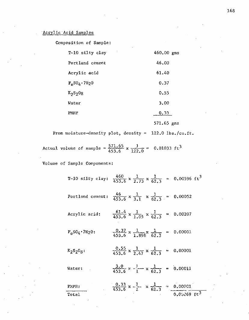
Acrylic Acid Samples
Composition of Sample:
T-10 silty clay
Portland cement
Acrylic acid
FeS04*7H20
K2s2°8Water
PMHP
From moisture-density plot, density =
460.00 gms
46.00
61.40
0.37
0.55
3.00
0.33
571.65 gms
122,0 Ibs./cu.ft.
Actual volume of sample = x — = 0.01033 ft3453 • o 1.22* 0
Volume of Sample Components:
460T-10 silty clay: 4 5 3 ^ * ^ X
Portland cement:
Acrylic acid:
FeS04*7H20:
k2s2°8:
Water:
PMPH:
46 1x
73 62.3
1x453.6 3.1 62.3
61.4 1 3x -— - x453.6 3.05 62.3
0.37 x _1 x J L
Total
453.6 1.898 62.3
0.55 JL 1453.6 2.47 X 62.3
3.0 .1_ _JL 453.6 X "l X 62.3
0.33 3_ 1453.6 “1 ‘ 62.3
= 0.00596 ft"
= 0.00052
« 0.00207
= 0.00001
= 0.00001
= 0.00011
0.00001 0.00c’69 ft3

Free Volume _ (actual vol.) - (vol. of components) x ^00When Molded actual volume
0.01033 - 0.00869 x 100 0.01033
- 15.87%
Composition of Sample:
T-10 silty clay 400 gms
Portland cement 40
Acrylic acid 175
Adjusting to same basis as previous acrylic acid sample:
T-10 silty clay 460 gms
Portland cement 46
Acrylic acid 201
Volume of Sample Components:
T-10 silty clay: 0.00596 ft3
Portland cement: 0.00052
Acrylic acid: ^ x ^ - 0.00677
Total 0.01325 ft3

VITA
Howard Morelock Elder, Jr., was born on January 22, 1941, in
Pine Bluff, Arkansas. Havingi moved to El Dorado, Arkansas, in 1945, he
was graduated from El Dorado High School in 1959. The following two
years he spent at Centenary College in Shreveport, Louisiana, before
transferring to Louisiana Polytechnic Institute in Ruston, Louisiana,
In 1963 he received a Bachelor of Science Degree in chemical engineer
ing from Louisiana Polytechnic Institute. In September of 1963, he
entered Louisiana State University as a full time graduate student and
was awarded a Master of Science Degree in chemical engineering in 1965.
After his senior year at Louisiana Polytechnic Institute, he
was employed for the summer by E. I. du Pont de Nemours and Company at
Victoria, Texas. This was followed by successive periods of summer
employment at the Monsanto Company in Texas City, Texas; Ethyl Corpora
tion in Baton Rouge, Louisiana; and DuPont in Wilmington, Delaware.
After completing his work toward the PhD degree in chemical
engineering, he accepted employment with the DuPont Company in Victoria
Texas.
In 1965 he married the former Sandra McCuistion of El Dorado
Arkansas.

EXAMINATION AND THESIS REPORT
Candidate: Howard M orelock E ld er , J r .
Major Field: Chemical Engineering
Title of Thesis: Space Polymers and Ionomers in Soil-Cement
Approved:
Malar Professor and Chairman
Dean of the Graduate School
EXAMINING COMMITTEE:
Date of Examination:
Ju ly 17, 1967