space flight validation of design and engineering of the ... · pdf filewhile a tms320c54...
TRANSCRIPT
Contents lists available at ScienceDirect
Chinese Journal of Aeronautics
journal homepage: www.elsevier.com/locate/cja
Chinese Journal of Aeronautics 25 (2012) 725-738
Space Flight Validation of Design and Engineering of the ZDPS-1A Pico-satellite
YANG Mua, WANG Haoa,* , WU Changjub, WANG Chunhuia,
DING Liconga, ZHENG Yangmingb, JIN Zhonghea aDepartment of Information Science and Electronic Engineering, Zhejiang University, Hangzhou 310027, China
bSchool of Aeronautics and Astronautics, Zhejiang University, Hangzhou 310027, China
Received 28 June 2011; revised 9 August 2011; accepted 19 September 2011
Abstract
The ZDPS-1A pico-satellites are the first satellites in China within the 1-10 kg mass range that are successfully operated on orbit. Unlike common pico-satellites, they are designed to be “larger but stronger” with more powerful platforms and unique payloads so as to bear a better promise for real applications. Through their space flight mission, the functionality and perform-ance of the two flight models are tested on orbit and validated to be mostly normal and in consistency with design and ground tests with only several inconforming occasions. Moreover, they have worked properly on orbit for one year so far, well exceed-ing their life expectancy of three months. Therefore, the space flight mission has reached all its goals, and verified that the design concept and the engineering process of the pico-satellites are sufficient in allowing them the desired functionality and perform-ance in, and the adaption to the launch procedure and the low-Earth orbit space environment. In the foreseeable future, the plat-form together with the design concept and the engineering process of the pico-satellites are expected to be applied to more com-plicated real space applications.
Keywords: systems engineering; ZDPS-1A pico-satellite; space environmental adaption; space flight; track telemetry and control;
attitude control
1. Introduction1
The first pico-satellites ever were the pair of thread-connected satellites made by Aerospace Corpo-ration for the Orbiting Pico-satellite Automation Launcher (OPAL) Project of Stanford University [1]. The satellites were launched on February 7th, 2000, and accomplished their experiments of mutual and ground contacts, and MEMS switch triggering after-wards. Since then, the development of pico-satellites has seen a rapid growth across the globe, with univer-
*Corresponding author. Tel: +86-571-87953857. E-mail address: [email protected]
Foundation item: National Natural Science Foundation of China (60904090)
1000-9361 © 2012 Elsevier Ltd. doi: 10.1016/S1000-9361(11)60439-1
sities and colleges making a major contribution. The most significant achievement among it was probably made by the “CubeSat” Project initiated by Stanford University and California Polytechnic State University and joined by over 20 research institutes around the world [2-3]. The project was not only able to regulate an applicable standard for pico-satellite design, manufac-turing and launching, but yield a lot of satellite models. For example, the Intelligent Space Systems Laboratory of Tokyo University built pico-satellites aimed at de-ploying large membrane structures for solar panels, telecom antennas or space fragment capturing on orbit [4-6]
. Also, Hankuk Aviation University of Korea designed and manufactured the HAUSAT-1 pico-sat-ellite for experimenting of GPS-based autonomous or bit determination, solar panels and sensor deployment, and onboard health data gathering via various sensors [7]. Moreover, some of them have gone through flight ex-Open access under CC BY-NC-ND license.

· 726 · YANG Mu et al. / Chinese Journal of Aeronautics 25(2012) 725-738 No.5
periments and missions. The DARTSat from Dart-mouth University was successful in all its experiments of electric power supply, tele-control, passive attitude control and payloads [2]. In addition, the goals of Earth observation with a miniature camera, on-orbit qualifi-cation of a GPS receiver, and technology demonstra-tion of the satellite platform, in particular the magnetic attitude control system of the COMPASS-1 pico-satellite developed by Aachen University of Applied Sciences in Germany were fulfilled during its space flight mis-sion [8].
Nevertheless, China witnessed very limited pro-gresses in the field of micro- and smaller satellites during the past ten years. Only Shanghai Micro-satellite Engineering Center of Chinese Academy of Science, Tsinghua University and Harbin Institute of Technol-ogy were able to design, manufacture and launch sev-eral micro- and nano-satellites respectively [9-11].
The ZDPS-1A pico-satellites developed independ-
ently by Zhejiang University, China, are the first satel-
lites in the country within the 1-10 kg mass range suc-
cessfully operated on orbit thus validating the suffi-
ciency of their development. Unlike the pico-satellites
introduced above, the design of the ZDPS-1A
pico-satellites does not strictly comply with the popu-
lar CubeSat-standard restraints of mass below 1 kg and
external dimensions 10 cm 10 cm 10 cm . Instead,
they are slightly heavier (weighing approximately 3.5
kg) and larger (taking on a 15 cm 15 cm 15 cm
cube shape) to allow for higher functionality, per-
formance and space environmental adaption, thus
bearing a better promise for actual applications. The
primary power supply (solar cells) of the satellites
provides a significant margin beyond the energy- bal-
ancing level, whilst the secondary power supply
(Li-ion batteries) can sustain the operation of a satellite
for at least 10 h even without the former. The minia-
turized heterogeneous cold backup transponders on-
board are the smallest in size and power consumption
in China to realize track, telemetry and control (TTC)
in the universal S-band (USB). In order to ensure the
availability of the satellite-ground telecom link, the
transponders are further supervised and autonomously
switched when necessary by a dedicated single-event-
effect-immune logic device. Transcending most pico-
satellites [1-6], the ZDPS-1A pico-satellites employ an
active tri-axial stabilizing attitude control scheme to
achieve an Earth-pointing accuracy of 5°. Moreover, a
complementary metal-oxide semi-conductor (CMOS)
camera for panoramic Earth imaging that is also de-
veloped in-house by Zhejiang University is onboard.
A pair of ZDPS-1A pico-satellite flight models
(ZDPS-1A01 and ZDPS-1A02) was launched on Sep-
tember 22nd, 2010. Several goals were set for their
space flight mission, in order to validate the design
concept and the engineering process of the satellites.
1) Platform verification. The functionality, perf-
ormance and space environmental adaption of the sat-
ellites and their subsystems were to be validated in
space via on-orbit testing and operation.
2) Experimentation of miniaturized parts. The space
environmental adaption and application of the various
parts including the miniaturized commercial-off-the-shelf
(COTS) MEMS accelerometers and gyroscopes, the
in-house-developed panoramic CMOS camera and the
novel tri-junction solar cells were to be experimented.
3) Attitude determination and control experimenta-
tion. The correctness and effectiveness of the attitude
determination and control scheme were to be evaluated
via attitude de-tumbling and stabilizing experiments.
The two satellites functioned as expected and in
consistency with ground test results throughout their
space flight mission with only several occasions of
abnormalities, and reached all the goals of the mission.
Up to now (August 2011), the satellites are still work-
ing properly, thus having their on-orbit life expectancy
of three months well prolonged.
2. Satellite System Description
A ZDPS-1A pico-satellite takes on a15 cm 15 cm
15 cm cubic shape (excluding antennas) and weighs
approximately 3.5 kg, as stated above. The satellite is
composed of eight subsystems including electric
power supply (EPS), command execution unit (CEU),
TTC, attitude determination and control subsystem
(ADCS), onboard computer (OBC), mechanical struc-
ture (MS), thermal control (ThC) and payloads (PLD).
The former seven subsystems form the platform of the
satellite. While the former three form a minimum
combination of subsystems for sustaining the satel-
lite-ground telecom, or the “minimum system”. Fur-
thermore, an external disengaging gear (DG) provides
the satellite with mechanical and electric interfaces
with launch vehicles. The parts for building the satellite
and the DG are all COTS and meant for industrial ap-
plication, unless noted otherwise. Pictures of the flight
models and one of their DGs are shown in Figs. 1-2.
Fig. 1 ZDPS-1A satellite flight models (in the foreground) and a DG (in the background).

No.5 YANG Mu et al. / Chinese Journal of Aeronautics 25(2012) 725-738 · 727 ·
Fig. 2 A ZDPS-1A satellite flight model installed in its DG.
The EPS subsystem [11] is equipped with domesti-cally-produced tri-junction Ga-As solar cells as the
primary power. The cells have a 26.8 theoretical efficiency. To ensure a sufficient power supply under any attitudes, the cells are tiled on all six planes of the satellite body. A Li-ion battery pack of five cells from Sanyo serves as the secondary power. A non-regulated bus whose voltage fluctuates between 3.0 V and 4.2 V is threaded throughout the satellite. Other than the primary and secondary power, the bus can also be powered externally via a pair of contactors on the sur-face of the satellite. The motive behind this scheme is to be explained in detail later. Furthermore, the supply and distribution circuits composed of DC/DC convert-ers and low-dropout regulators (LDOs) are parallel connected to the bus. They transfer the bus voltage to usable regulated voltages to other subsystems.
The CEU subsystem is an A54SX series anti-fuse field programmable gate array (FPGA) from Actel for power control and health supervision for subsystems and crucial features (including the processors of the TTC, ADCS and OBC, and the satellite-ground tele-com) by passively responding to commands and auto-nomously judging heartbeats respectively.
The TTC subsystem works under the universal
S-band TTC system. It is composed of two heteroge-
neous cold backup transponders and two homogeneous
hot backup sets of passive antennas. The analogue
transponder [12] enjoys uplink and downlink data rates
of 125 bit/s and 1 024 bit/s respectively, a reception
sensitivity of �90 dBm and a transmission power of
100 mW. While the digital one [13-14] bears merely the
same features except for its �100 dBm sensitivity. The
former also provides a radio-frequency (RF) front-end
composed of a pair of hot backup power amplifiers
(PA) and a low-noise amplifier (LNA), which are
shared with the digital one. The transponders have
several working modes including incoherent, and co-
herent with and without ranging side-tone forwarding.
Moreover, a set of four-arm self-phase-shifting helix
antennas are mounted on two diagonal vertices on the
+/�z planes (to be defined later) respectively. The ADCS [15-16] is a close-loop control system with
rich peripherals. A major and a backup magnetometer, a cosine and a differential Sun sensor form its trans-
ducer matrix. Other than the major magnetometer HMR2300 from Honeywell, all the transducers are developed in-house. A tri-axial MEMS gyroscope formed by 3 orthogonally-installed single-axis gyro-scope parts (ADXRS401) from Analog Devices (ADI) is also present as a transducer, but more for experi-menting than attitude determination. Three major magnetic torque coils, four backup magnetic torque coils and a fixed-bias momentum flywheel (motor model being 2224SR from Faulhaber) on the pitching axis serve as actuators. While a TMS320C54 series digital signal processor (DSP) from Texas Instruments (TI) performs the duty of the controller via running sampling, computing and actuating algorithms. There-fore, the subsystem is able to perform dual-vector (so-lar and Earth-magnetic) attitude determination and tri-axial stabilizing attitude control with Earth-pointing precision of 5° when the Sun is visible. Or in eclipses, it carries out angular velocity estimation and de-tumbling that restrains the angular velocity below 1 (�)/s.
The OBC [17] resorts mainly to two warm backup (one is hot while the other is powered up but remains in reset status) 8052-based microcontrollers from ADI to practice onboard data handling. It collects raw en-gineering data including voltages, currents, tempera-tures and mechanical-electric connectivity from dif-ferent sampling spots, state data from CEU, processed data from the TTC and ADCS, and PLD data. The OBC formats and stores the data for real-time and de-layed telemetries. Also, it makes use of it to deduct occurrences of crucial events, the sufficiency of the electric power supply, and the health of the TTC and ADCS, to carry out pre-defined operations and take necessary maintenance actions according to the flight program. Meanwhile, it receives tele-control com-mands and injected data demodulated and decoded by the TTC. It executes them for power management, telemetry re-formatting, flight program branching and PLD utilization, or passes them on to their ultimate destinations like the ADCS or the real-time clock (RTC) in the OBC that provides the satellite with a time reference.
The MS of the satellite is mainly composed of three aluminum parts, a quadruplet, a set of two covers, and a U-shape frame. All printed circuit boards (PCB) are first installed onto the U-shape frame. Such a union is further fixed onto the quadruplet. The quadruplet and the two covers are then assembled into the cube-shaped shell of the satellite, whose six planes are named +/�x, +/�y and +/�#z in correspondence to the ontology coordinate system respectively. The system is thus defined that x, y and z axes correspond to the rolling, pitching and yaw axes of the satellite body, and each of the two x, y and z planes are therefore perpendicular to those axes, respectively. The MS pro-vides the satellite mainly with the mechanical strength for surviving the enormous stresses of vibration, shock and acceleration during the launch. Also, it serves the internal electronic subsystems as a shield for the total dose effect in ionized radiation.

· 728 · YANG Mu et al. / Chinese Journal of Aeronautics 25(2012) 725-738 No.5
A passive instead of active ThC subsystem is ap-
plied to the satellite in order to save the very limited
electric power onboard. It makes the satellite an iso-
thermal body and insulate it from the heat gain from
the Sun and loss to the cold background. Thus, it can
restrain the temperature of the electronic subsystems
within their comfort ranges of �20-55 oC. In addition,
17 temperature sensors are installed on the shell, the
U-shape frame, the PCBs and the Li-ion battery pack
respectively to supervise the heat distribution and
temperature fluctuation of the satellite, and to validate
the design of the ThC subsystem.
A tri-axial MEMS accelerometer composed of a dual-axis accelerometer part (ADXL203) and a sin-gle-axis one (ADXL103), both from ADI, and an in-house-developed panoramic CMOS camera form the PLD subsystem. They are carried onboard for space application and utilization experimenting.
The DG, also made of aluminum, connects the satel-
lite mechanically and electrically to launch vehicles as
mentioned above. Structurally, it is a cage with a spin-
ning hatch. Before the launch, the satellite is inserted
into it via four solid-lubricated rails in contact with
four edges of the satellite. This process also com-
presses a cone spring to zero height. The hatch is then
closed and has its position fixed by a titanium bar and
a group of nuts. Such a closed cage restrains the satel-
lite’s motion during the launch. At separation, the
launch vehicles fire an explosive device (ED) to cut
the titanium bar. This allows the hatch to automatically
spin open, and the cone spring to stretch itself to push
the satellite into space. Such a separation scheme is
designed to provide the satellite with a theoretical av-
erage injection velocity relative to the vehicle (vi) of
1.37 m/s, and a theoretical initial tumbling angular
velocity (i) of no more than 3 (°)/s. As for the electric
interface, besides the ED control signal, two pairs of
contactors are installed on the internal and external
surfaces of the DG and the satellite respectively, whose
connectivity is transmitted to and supervised by the
vehicle for separation outcome judgment. In addition,
a similar Li-ion battery pack is present to power the
satellite before and during the launch in the space
flight mission via the contactors of the EPS subsystem
as stated above, in order to preserve more of the satel-
lite’s internal power storage for on-orbit operations.
3. Space Flight Mission Outline
The space flight mission of the ZDPS-1A pico- satellites is composed of three time-consecutive phases, namely launch, on-orbit test and long-term manage-ment. The launch of the flight models was handled at Jiuquan Satellite Launch Center (JSLC) of China. Twenty-one days prior to the scheduled launch, the space flight mission crew entered JSLC to initiate a series of pre-launch tests to confirm the health of both
the flight models and their DGs, and to set their launch status up. The standardized launch procedure of the pico-satellites was delivered by a two-stage Long- March-2D (CZ-2D) rocket in a piggybacking pattern with the YG-11 satellite. At 10�42�03 (t0) Beijing time
on September 22nd, 2010, the vehicle carrying the two flight models took off from JSLC. After the consecu-tive events of pitchover, first-stage shutdown and separation, fairing separation, second-stage main and vernier thrusters shutdown, and YG-11 separation, the two flight models were both injected perpendicularly to the vehicle heading into orbit at t0+787 s.
The approximately 13 min launch was considered to be the most crucial and harshest phase throughout the whole mission, due to the extreme complication and drastic variation of the environment. Therefore, for the launch phase, ground operation (service provided by Xi’an Satellite Control Center (XSCC) of China) was mainly aimed at tracking the signals and telemetries from the flight models so as to monitor their status and health conditions. No tele-control was introduced or allowed due to the potential risks of such operations. During this phase, all the expected changes in teleme-tries (to be explained in the following sections) took place for both of the flight models, while all other te-lemetry channels remained the same as before it. The normal results of autonomous onboard supervision conducted by the CEU and the OBC further confirmed the fact that all modules and subsystems functioned well during the phase. In conclusion, the flight models were able to endure the environment of the launch phase, and the design and construction process of the ZDPS-1A pico-satellites were adequate for it.
The separation of both flight models were success-
ful, since the telemetries of the vehicle for the two
pairs of contactors on the DG, and those of the flight
models for the two position switches for separation
outcome judgment all came in right. vi and i were the
two major figures to quantize the outcome of the
separation as stated above. vi can be derived from di-
viding the depth of the DG by the time lag between the
actions of the two switches recorded by the OBC. The
lags of the flight models were 0.275 s and 0.375 s re-
spectively, suggesting that vi is 1.37 m/s and 1.00 m/s
respectively. For ZDPS-1A01, the velocity was just as
designed. While for ZDPS-1A02, it was 27 slower
than the designed value, yet still within an acceptable
range; i was directly measured by the ADCS. The
figures were approximately 4 (°)/s and 2 (°)/s respec-
tively (observed after the separation). Although the
former exceeded the design restraints, it did not affect
the operations in the succeeding phases. Once on orbit, the on-orbit test phase for the flight
models initiated. This phase aimed at obtaining the real-time and delayed telemetries, and testing and verifying the correctness of the functions and the de-cency of the performances of both the flight models, via ground TTC operations within the first 37 orbits

No.5 YANG Mu et al. / Chinese Journal of Aeronautics 25(2012) 725-738 · 729 ·
(first three days on orbit). During the first three orbits, ground operations mainly concentrated on observing the various formats of real-time and delayed teleme-tries, in order to estimate the health of the flight mod-els after the launch phase and through the environment transition from ground to space. For the rest of this phase, a series of tests was carried out for a nearly- full-coverage test of all functions and performance figures of both the flight models. The success of this phase then led the space flight mission to its final phase, long-term management. In this phase, experi-ments with backup parts and modules were carried out, along with the ritual maintenance on a daily basis. This phase was supposed to end as the life expectancy of three months does for both the flight models. However, up to now, they have stayed quite healthy on orbit, and already lived for over nine months.
4. Platform Verification
The functionality, performance and space environ-
mental adaption of the platform were verified to be
correct and in consistency with mission and design
requirements, through tracking, tele-control, observa-
tion and analysis of telemetries throughout the space
flight mission. Although several minor design flaws
and operation abnormalities were found, they did not
ruin the big picture.
4.1. EPS
During the launch phase, the fairing separation al-
lowed the solar cells to be directly exposed to the sun-
light or the earthshine, thus able to generate electric
power. Figures 3-4 depict the changes in the output
voltages and currents of the solar cells on ZDPS-1A02
respectively around the fairing separation. The figures above show that shortly after the fairing
separation, at t0+190 s, the voltage and current output of the solar cells on all planes of ZDPS-1A02 stepped up at different levels. This means that the solar cells were able to generate electric power from the sunlight and the earthshine in space. Note that the increasing levels of the output voltages from the cells on different planes were uneven, and that those of the currents were little. This was because that the planes were partly shadowed by the DGs, and the cells on the earthshine-exposed planes generated far less power than those exposed to the sunlight, since the intensity of the former is much weaker than that of the latter.
The story of ZDPS-1A01 was similar, except the +z
plane solar cells and the slightly later step-up of the
output. The +z plane cells failed right before the
take-off since structural operations then damaged their
wiring that are very close to the operation spot. How-
ever, since all of the other five solar panels generated
significant electric power, they were validated to all
function well during the launch phase. Also, the step-up
Fig. 3 Change of solar cell output voltages of ZDPS-1A02 in launch phase.
Fig. 4 Change of solar cell output currents of ZDPS-1A02 in launch phase.
of the output took place 7 s later than that of ZDPS-
1A02 due to the difference in their installation loca-
tions on the vehicle, thus the illumination transition as
the fairing left the vehicle.
During the on-orbit test phase, tests of the EPS sub-system of the two flight models were mainly com-prised of the health check and the performance evalua-tion of the solar cells, the Li-ion battery packs and the supply and distribution circuits, together with the es-timation of the overall EPS balance. While in the long-term management phase, no operation other than telemetry supervision was carried out.
For ZDPS-1A02, sample readings show that the output voltages of the solar cells on all planes were between 4.5 V and 5.0 V under the sunlight, and be-tween 0.5 V and 2.0 V in eclipses; while the output currents were between 0.1 A and 1.0 A, and remained �0.156 A respectively. For example, Figs. 5-6 show the
output voltage and current of the solar cells on the +z plane respectively. Note that the voltage and current fluctuations were caused by the day and night alterna-

· 730 · YANG Mu et al. / Chinese Journal of Aeronautics 25(2012) 725-738 No.5
tion on orbit and the slowly-spinning attitude. There-fore, the solar cells were functioning well and able to generate electric power on orbit as assumed. The simi-lar conclusion stands for all cells but the ones on the +z plane for ZDPS-1A01, only with the plateaus of voltages at 5.0 V, lasting much shorter in time then due to its faster spinning.
Fig. 5 Output voltages of solar cells on +z plane of ZDPS-
1A02 on 2nd day on orbit.
Fig. 6 Output currents of solar cells on +z plane of ZDPS-
1A02 on 2nd day on orbit.
The figures also reveal several design flaws in the voltage and current sampling circuits. A margin not enough was left for the sampling range of the former. So the readings had very long plateaus at 5.0 V, indi-cating that for most of the time then, the actual volt-ages exceeded the value. On the other hand, a flaw in the latter left some of the current readings below zero, or �0.156 A to be specific. Such values had no physi-
cal significance since the solar cells were designed unable to consume power from their loads. The reason for such readings to occur is that for inputs signifi-cantly above zero, the circuit adds an offset of 0.156 A. While for those near zero, the analog to digital transfer is not linear. Yet for simplicity, the transfer equation simply subtracts 0.156 A from the transferred value. This causes the readings below 0.156 A to be below zero eventually. Yet for ground operations, the current
readings below zero can simply be considered zero. The power output capability of solar cells on one
plane can hardly be known for sure since the chance of the inclination angle of the sunlight being zero degree on them is very slim. However, the maximum products of the output voltages and currents throughout the te-lemetries can be used to estimate it, although such an estimated value has to be lower than the real one. Ta-bles 1-2 present the results of such estimation and the original results of ground tests for both the flight mod-els respectively.
Table 1 Maximum power output of solar panels of ZDPS-1A01
Maximum power output/W Solar panel
On bit Ground test
�y 5.633 5.269
+x 5.657 5.412
+z 0 3.991
+y 5.318 5.216
�x 5.634 5.395
�z 5.324 4.954
Table 2 Maximum power output of solar panels of ZDPS-1A02
Maximum power output/W Solar panel
On-orbit Ground test
�y 4.699 5.227
+x 4.498 5.363
+z 3.353 4.001
+y 0.396 5.243
�x 4.602 5.331
�z 4.993 4.960
The tables show that the solar cells on all planes
other than the +z plane on ZDPS-1A01 had their
maximum on-orbit power output larger than the
ground tested figures. This is because the sunshine was
attenuated by the atmosphere during ground tests. The
estimated values for most of the cells of ZDPS-1A02
were slightly lower, and that on the +y plane was sig-
nificantly lower. A more detailed analysis suggests that
since the voltage readings of the cells often reached
the sampling range as stated above, their power output
were quite under-estimated.
The Li-ion battery packs were charged under the sunlight and discharged during eclipses. Their terminal voltages are equal to those of the satellites’ buses since they are directly connected to the latter in parallel. For both flight models, the packs worked with the terminal voltage of approximately 4.60 V and 4.40 V during charging and discharging respectively for the first days on orbit. Such voltages were significantly above the designed level of 4.20 V, and harmed the batteries by overcharging them. Consequently, the storage capacity of the packs dropped rapidly as time went by. ZDPS-1A01 had lost its solar cells on the +z plane

No.5 YANG Mu et al. / Chinese Journal of Aeronautics 25(2012) 725-738 · 731 ·
before the launch as stated above. This decreased the overall power input and left the overcharge less intense than ZDPS-1A02. For instance, the charging currents of the packs ranged from 0.34 A to 0.69 A and from 0.68 A to 1.14 A for ZDPS-1A01 and ZDPS-1A02 respectively within the same orbit on the second day on orbit. Therefore, on the 159th day on orbit, the ter-minal voltage dropped to approximately 4.30 V and 4.05 V during charging and discharging respectively for ZDPS-1A01, and approximately 4.25 V and 3.90 V for ZDPS-1A02. This reflects a flaw in the EPS sub-system design that the case of excessive power input was not considered. Should it occur, there is no way to dissipate it other than to overcharge the battery packs and/or heat the solar cells themselves, thus both caus-ing undesirable consequences.
Load currents reflected the functionality and the performances of the power supply and distribution circuits. For both flight models, they were mostly steady and in consistency with ground tests. Mid-values of the readings of ZDPS-1A02 are given and compared to the ground-tested values in Table 3.
Table 3 Mid-value readings of load currents of ZDPS-1A02
Mid-value reading of load currents/A Target of power supply On orbit Ground-test
PA and LNA 0.240 0.250
Analogue TTC transponder
0.300 0.290
Digital TTC transponder
0.340 0.350
CEU 0.014 0.015
Flywheel 0.023 0.023
All load currents kept normal throughout the space flight mission, except that for reasons explained later, the spinning of the flywheels on both of the flight models significantly slowed down and eventually stopped, and their currents grew to and remained 0.045 A (upper limit of the sampling range) ever since 19:00, September 23rd, 2010. According to the overall power consumption change afterwards, the currents absorbed by the failed flywheels were way above the readings and up to approximately 0.45 A. This reveals yet an-other defect in the sampling circuit margin. Thereafter, they were shut down manually via tele-control to pre-vent fault spreading.
The overall EPS balance can be estimated using a large collection of on-orbit data. Calculations show that with the failed flywheels shut down and before drops of the storage capacities of the Li-ion battery packs took apparent effect, the balances for ZDPS-1A01 and
ZDPS-1A02 were reached at 106 to 111 and 116
to 121 of the stored quantities of the packs before the launch respectively. This again shows that the overcharge for the pack of ZDPS-1A02 was more in-tense than that for the pack of ZDPS-1A01.
Via tests and utilization, the functionality of the EPS of both the flight models was verified to be correct. The performance figures of the subsystems were mostly in consistency with design and ground tests, although the performances of the Li-ion batteries were degraded by the overcharging. Even so, they were still able to sustain the operation of the satellites in eclipses long after the life expectancy was reached. In all, the EPS worked well in the space environment to supply sufficient electric power to other subsystems.
4.2. CEU
The two functions of the CEU, power control and health supervision, were validated during the two phases for both the flight models. Statistics show that during the whole space flight mission, total numbers of more than 30 and 50 tele-commands concerning power control were sent to ZDPS-1A01 and ZDPS-1A02 respectively, with all successfully executed onboard. Since the executions were eventually carried out at the CEUs, their power control functions were thus vali-dated.
The CEU also watched out for the onboard proces-sors and the satellite-ground data link, as mentioned above. At around 09:30 on March 20th, 2011, the digital TTC transponder on ZDPS-1A01 that had been turned on for experimenting purposes was found not responding to any tele-commands for reasons to be explained later. The situation lasted for 55 hours and 14 minutes, and until the link watchdog of the CEU detected that during that period much longer than the pre-defined maximum interval between tele-commands of 24 h, no tele-command was received onboard, and autonomously reset the transponder. This validated the health supervision function of the CEU although none of the other watchdogs were triggered.
4.3. TTC
The functionality and performance of the trans-ponders were directly validated to be correct and in consistency with design along with the space flight mission execution. This also indicates that they bore adequate space environmental adaption except that the digital transponders may be susceptible to soft errors induced by single event upsets (SEUs).
During the launch phase, the analogue transponders
on both of the flight models worked properly
throughout it, despite all the adverse factors that har-
assed the coherent duplex satellite-ground telecom link
for track and telemetry. The orientation and attitude of
the vehicle were highly dynamic. This caused both the
ground and onboard signal reception levels to vary
enormously. Also, the fairing served as a radiation
shield before it was tossed. Thus, the compound radia-
tion patterns of the onboard transmission and reception
antennas were significantly different from their respec-

· 732 · YANG Mu et al. / Chinese Journal of Aeronautics 25(2012) 725-738 No.5
tive designs. Moreover, the ignition of the two stages
of the vehicle, and the firing of the EDs for separations
of the fairing, the first stage and YG-11 introduced
bursting electro-magnetic interferences. They would
potentially cause temporary malfunctioning of the on-
board electronics, especially the RF transmission of
downlink signals and telemetries. Nevertheless, all the
three TTC stations under the vehicle trajectory suc-
cessfully picked up signals and continuously received
telemetries from the satellites in their relaying visible
arcs as scheduled. Also, telemetries of the uplink lock
status bits of both the transponders remained set
throughout the arcs, indicating stable onboard recep-
tions of the uplink signals.
Thereafter, TTC stations tracked the passing flight
model to measure its relative range and velocity in
order to determine its orbital elements; received, de-
modulated and decoded the telemetries; transmitted
tele-commands and injected data.
Statistics of their respective tracking errors show that the accuracies of range and velocity measurement of the three transponders that were tested (both the analogue and digital transponders on ZDPS-1A01 and the analogue one on ZDPS1A-02) were in the 10 m and 10 cm/s orders of magnitude respectively. Table 4 gives two samples of tracking errors within one con-tact for each transponder.
Table 4 Samples of tracking errors
Transponder Orbit of
measurement Random error
of range/m
Systematic error
of range/m
3 2.99 11.51 ZDPS-1A01 analogue
transponder 9 8.74 14.47
3 6.60 0.11 ZDPS-1A02 analogue
transponder 15 1.97 8.36
356 6.09 12.44 ZDPS-1A01 digital
transponder 371 �4.34 6.44
Transponder
Random error of veloc-
ity/(cm·s�1)
Systematic error of veloc-
ity/(cm·s�1)
10.88 �16.90 ZDPS-1A01 analogue
transponder 11.45 ��5.36
13.64 �13.25 ZDPS-1A02
analogue transponder �7.60 4.60
6.45 11.45 ZDPS-1A01 digital
transponder �7.49 13.31
The duplex communication between the flight mod-els and ground stations turned out to be reliable. For the RF downlink, the transmission powers were proven to meet the requirements since the readings of the output power detection voltages of the PAs (with examples given in Table 5) were consistent with the ground-tested values and the ground receptions of the
downlink signals were steady. As for the uplink, the onboard auto-gain control (AGC) voltages reflected the reception levels of uplink signals. The minimum on-orbit values of the AGC voltages (also given in the table above) indicated the signal levels received to be around �88 dBm. This was very close to their nominal
sensitivities of �90 dBm. Since the latter could hardly
be tested as the channel condition and the transmission power of the ground station during one contact were fixed, the reception sensitivities of them can both be considered to conform to requirements. This also left reception sensitivity for the digital transponder on ZDPS-1A02 not testable, which is �100 dBm theoreti-
cally.
Table 5 Samples of telemetries indicating qualities of satellite-ground telecom
Detection voltage/V
Transponder On-orbit PA1
power
Ground- tested PA1
power
On-orbit PA2
power
Ground- tested PA2
power
ZDPS-1A01analogue
transponder 0.71 0.60-0.80 1.02 0.90-1.10
ZDPS-1A02analogue
transponder 0.95 0.80-1.00 0.87 0.70-0.90
ZDPS-1A01digital
transponder 0.77 0.70-0.90 1.07 0.90-1.10
Minimum AGC voltage under coherent mode/V
Transponder
On-orbit Ground-tested
ZDPS-1A01 analogue
transponder 0.39 0.37
ZDPS-1A02 analogue
transponder 0.34 0.316
ZDPS-1A01 digital
transponder N/A N/A
As far as the baseband data communication is con-
cerned, processing with the telemetries from the three
transponders turned out to be mostly successful. The
only trouble met was that for a certain series of reasons,
the telemetries for attitude angles were very occasion-
ally erroneously locked as the synchronizing word of
the telemetry frames. First, when the ADCS had no
usable orbital element data, the telemetries for attitude
angles would remain a specific constant pattern. The
concatenation of parts of the constant pitching and yaw
angles could form a word that had only a single-bit
difference from the inverse code of the frame synchro-
nizing word. Moreover, the downlink data were modu-
lated with differential phase shift keying (DPSK) that
naturally bore a 180� phase ambiguity. Also, the te-
lemetry frame synchronizing scheme could tolerate the

No.5 YANG Mu et al. / Chinese Journal of Aeronautics 25(2012) 725-738 · 733 ·
single bit error. Such a trouble was tackled by clearing
the relevant data in the telemetry via turning the ADCS
off to stop the relevant data from being continuously
transmitted to the OBC, switching the micro-control
unit (MCU) of the OBC to restore the telemetry chan-
nels in question to zero thus sabotaging the telemetry
frame synchronization established on the ground using
the erroneously concatenated synchronizing word, and
turning the ADCS back on consecutively through
tele-commands.
Tele-control using the three transponders was also successful. Throughout the whole space flight mission, total numbers of more than 950 tele-commands and pieces of injected data were sent to each of the flight
models respectively, with only less than 1 of them rejected due to the fading of the satellite-ground tele-com channel. As has been mentioned above, the digital TTC transponder of ZDPS-1A01 was found not to respond to any tele-command or pieces of injected data on March 20th, 2011, the problem of which was not solved until the link watchdog of the CEU reset the transponder. The most probable reason for this was that an SEU-induced soft error affected the uplink function of its FPGA (Virtex IV from Xilinx). The SRAM-based device was quite large in scale, thus ex-tremely susceptible to SEUs that are a major threat to spaceborne electronics [18]. Also, the DSP of the trans-ponder worked properly since the telemetry was nor-mal, and the watchdogs for it in the CEU and the OBC were neither triggered. Regrettably, due to the lack of observation means, the guess could not be validated with more solid evidence.
4.4. OBC
The successful functional tests for the OBCs were mainly collaterally performed along with the tests of
other subsystems
) The legitimate telemetries with correct organiza-
tion and refreshing rates of all subsystems validated their functions of onboard data handling and telemetry formatting. Besides, since all telemetry formats in-cluded time stamps posted by the RTC onboard the OBC, and all delayed telemetries were stored in the EEPROMs, the functionalities of both modules were also validated.
2) The total numbers of more than 850 tele-control operations on each flight model that were handled by the OBCs all yielded correct responses. This validated their tele-control processing functions.
3) The separation events were handled by the OBCs correctly, as they both managed to give the two man-datory attitude control mode switching commands to the ADCSs as stated above.
4) The EPS supervision and maintenance functions also took effect when the drop of the storage capacity of the Li-ion battery pack of ZDSP-1A02 eventually dragged the bus voltage below the 3.6 V threshold on
January 24th, 2011. In dealing with this, the OBC autonomously steered the satellite into a power-safe mode by shutting down the ADCS and the PLD sub-system to save power. Thereafter, although the condi-tion of exiting the mode stood as the voltage rose back to approximately 4.1 V after the eclipse, it was sus-tained by the OBC since autonomous exiting was pro-hibited in case the level of EPS should further deterio-rate.
5) The watchdogs for the TTC subsystem and the ADCS were never triggered on either flight model, which is consistent with the fact that all of them worked properly without being reset as explained ear-lier and to be explained later respectively.
6) Copies of the MIDI-formatted Anthem of Zheji-ang University that were pre-stored in the non-volatile memories within the MCUs of the OBCs were suc-cessfully downloaded.
Last but not least, the backup MCU onboard the OBC of ZDPS-1A02 together with the MCU switching scheme was tested collaterally with the solution of the frame synchronizing error met in the telemetry proc-essing as stated above, since it involved switching and sticking to the formerly warm MCU.
The only phenomenon that rang an alarm was the performances of the RTCs on both of the OBCs, as systematic drifts of approximately 5 s per day were discovered for them. Although such a lag represented a frequency error of 50 part per million of the frequency sources for the RTCs that fulfilled the performance requirements for them, it actually caused a lot of trou-ble for ground operations. As the time lag was consid-ered risky for the ADCSs, and no continuous time lag calibration function was available (which is a flaw as seen now), the RTCs had to be put back 5 s through data injection every day.
4.5. ThC
The changes in the heat environment throughout the space flight mission imposed a major threat on the flight models. Before the vehicle took off, the flight models were encapsulated in the fairing, which pro-vided a closed thermostatic space of approximately 25
oC. During the launch, however, as the vehicle es-caped from the Earth’s atmosphere and the fairing was detruded, they were directly exposed to the cold vac-uum background of �269 oC. Even as the heat dissipa-tion from the satellites was only available in the form of radiation then, and it was partly compensated by the input from the sunlight and generation from the on-board electronic subsystems, the tremendous tempera-ture difference caused a rapid drop of their temperature bases. However, the ThC subsystems on both of the flight models managed to minimize the impacts by the drops on the electronic subsystems. Also, they were able to balance the temperature fluctuation caused by the day and night alternation on orbit within an ac-ceptable level. Figure 7 depicts the temperature changes (with those of the +x plane and the ADCS as

· 734 · YANG Mu et al. / Chinese Journal of Aeronautics 25(2012) 725-738 No.5
examples) along time for ZDPS-1A02. All temperature readings experienced a major drop after the launch, but were balanced by the ThC subsystem since the 3rd orbit. The temperatures of the six planes varied more drastically and stayed lower than those of the electronic subsystems, while the latter stayed at around 10 oC and within their comfort ranges. The story was similar for ZDPS-1A01.
Fig. 7 Temperature change of ZDPS-1A02 on the 1st day on orbit.
The only flaw found in the ThC subsystem was that the temperature sensors would occasionally output sin-gular readings with full-bias values. Although the reason for this is unknown yet, such readings could be reasona-bly filtered out since no heat source or sink inside or outside the flight models could boost such rapid tem-perature changes for them. Therefore, such readings would not affect the evaluation of the heat balancing.
4.6. MS
The MS subsystem is mainly meant to cope with the intense mechanical stresses during the launch phase, so as to provide the electronic subsystems with reliable mechanical and electric interconnections for power supply and information exchange for proper function-ing. Specifically, the ignition of the two stages and the firing of the EDs of the vehicle caused mechanical shocks. Also, before it escaped from the Earth’s at-mosphere, the friction of the rocket body with the sur-rounding air caused both sine and random vibrations. In addition, the acceleration of the vehicle caused axial and lateral loads of 8g and 2g respectively. Yet despite all these stresses, telemetries of all the electronic sub-systems of both flight models all came in with correct refreshing rates carrying legal values. Thus it can be concluded that all modules and subsystems and the vast electric interconnections between them had func-tioned well during the launch, and were not affected by the mechanical stress.
5. Experimentation of Miniaturized Parts
Four types of miniaturized parts, including the miniaturized COTS MEMS accelerometers and gyro-scopes, the in-house-developed panoramic CMOS
camera and the novel tri-junction solar cells were ex-perimented during the space flight mission. All of them were found to have successfully functioned and per-formed as expected in space, with the former two be-ing only capable of rough measurements, while the latter two presenting decent promises for realistic en-gineering purposes.
5.1. MEMS accelerometer
The MEMS accelerometers on both of the flight
models were able to record the acceleration during the
launch phase, as Fig. 8 depicts the readings of the
sensor on ZDPS-1A02. However, since the acceler-
ometers only bore a measurement range of �1.7g to
1.7g, and were sampled only once a minute, they could
not reflect thoroughly the dynamics then.
Fig. 8 Accelerometer readings of ZDP-1A02 during the launch.
While on orbit, the sensors gave steady readings. This is in consistency with the fact that the flight mod-els bore no acceleration when orbiting around the Earth. Figure 9 shows the readings of the sensors on ZDPS-1A02 on the 1st day on orbit. Note that the non-zero readings actually demonstrate the respective biases of the sensor in its three orthogonal measuring axes, and that the sensors in the latter two axes bear merely the same readings thus having their curves in the figure overlapped.
Fig. 9 Accelerometer readings of ZDPS-1A02 on the 1st day on orbit.
In all, the experiments of the accelerometers during

No.5 YANG Mu et al. / Chinese Journal of Aeronautics 25(2012) 725-738 · 735 ·
the launch phase and on orbit showed that they were
able to survive and function in space. But since their
measurement ranges are significantly narrower than
the actual dynamics, they provide only a rough obser-
vation means for such inertial parameters.
5.2. MEMS gyroscope
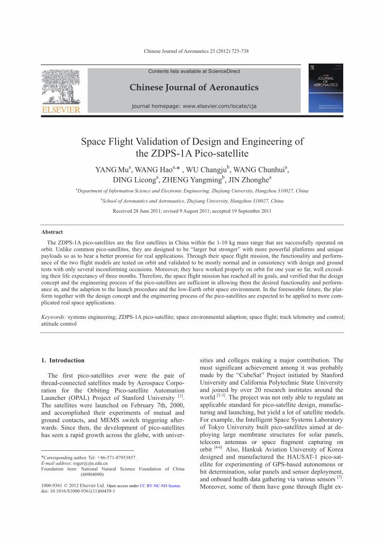
The MEMS gyroscopes onboard the flight models also functioned well with continuous output on orbit. Figure 10 depicts the output of that on ZDPS-1A02 during the initial de-tumbling (to be explained in Sec- tion 6). The measurements in the three axes have to be processed before being applied to indicate the real angu-lar velocity components. First, the zero-points of the three axes that were determined to be �1.0, �11.1, �7.4 (°)/s respectively during ground tests have to be sub-tracted from them. Second, a coordinate transfer has to be imposed, since the x, y and z components measured by the gyroscope actually represent those in the pitch-ing, yaw and minus rolling axes respectively. Thereaf-ter, it can be seen that the measurement components are consistent with those calculated by the ADCS, as given in Section 6. This suggests that the two angular velocity acquisition methods were mutually comple-mentary. That is to say, the gyroscopes are proven able to provide a rough measurement of angular velocities in space. However, as their accuracies are low since their measurement noises are as high as 0.2 (°)/s [19], and their zero-points have mid-to-long-term and tem-perature-variation-induced random drifts that can hardly be calibrated, the gyroscopes are inadequate as transducers for the ADCS.
Fig. 10 Angular velocity components of ZDPS-1A02 measured by the MEMS gyroscopes during the initial de-tumbling.
5.3. Panoramic CMOS camera
The panoramic CMOS cameras on both of the flight models were able to capture the Earth. Figure 11 shows the pictures taken by them respectively. Thus, the cameras have decent promises in space applica-tions, especially as Sun and Earth sensors in the future thanks to their panoramic imaging ability.
Fig. 11 Photos of Earth taken by panoramic CMOS camera on ZDPS-1A01 and ZDPS-1A02 respectively.
5.4. Tri-junction Ga-As solar cell
As stated above, the tri-junction Ga-As solar cells functioned well to provide both of the flight models with electric power supply. Their power transformation efficiency was among the best of all kinds of known solar cells, and witnessed no degradation over the 9-month period of operation. Therefore, they are ade-quate for and very competent for short-to-mid-term space applications on low-Earth orbits (LEOs).
6. Attitude Determination and Control Experi-mentation
The ADCS on both the flight models were able to
establish their tri-axial stabilized Earth-pointing atti-
tudes or keep their angular velocities of spinning very
low, as the goals of experiments anticipated. Moreover,
even when the flywheels failed, both subsystems were
still able to do the de-tumbling effectively, beyond the
design borders, thanks to the design idea of leaving the
margins as significantly as possible. Therefore, it can
be said that the functionality and the performance of
the ADCS were correct and in consistency with design,
all of its components except the flywheels were able to
survive in the space environment throughout the space
flight mission, and the underlying design concept was
successful.
· 736 · YANG Mu et al. / Chinese Journal of Aeronautics 25(2012) 725-738 No.5
6.1. De-tumbling
At t0+787 s, both of the flight models were sepa-rated from the vehicle into their respective Sun-synchronous and near-circular LEO, with heights approximately 650 km and periods approximately 96 min. The injection was accompanied by the mandatory switching of the attitude control mode into dou-ble-torque de-tumbling for both of them, which was held for 1 000 s. Afterwards, the mode was switched mandatorily again into normal-torque de-tumbling that was held for 9 000 s. Such a mandatory initial de-tumbling strategy was implemented in case the at-titude control mode should be incorrectly determined by the ADCS since it had never been validated in a space mission before. After the first 10 000 s on orbit, the attitude control modes of both the flight models were allowed to be autonomously decided by the ADCS.
The anticipated goals of the initial de-tumbling were reached for both the flight models. It was reasonable that ZDPS-1A02 managed to have its angular velocity damped to lower than 0.2 (°)/s within 1 700 s, much shorter than the time of 5 600 s for ZDPS-1A01, since i of the former was much smaller than that of the latter as explained earlier. Notably, although i of the latter was overproof, the margins within the design of the ADCS allowed it to be compensated, leaving no further impacts. The changes in angular velocity com-ponents on the three axes of the ontology coordinate system of ZDPS-1A02 are depicted in Fig. 12.
Fig. 12 Angular velocity components of ZDPS-1A02 during the initial de-tumbling.
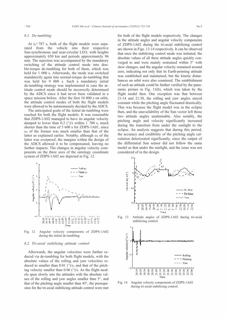
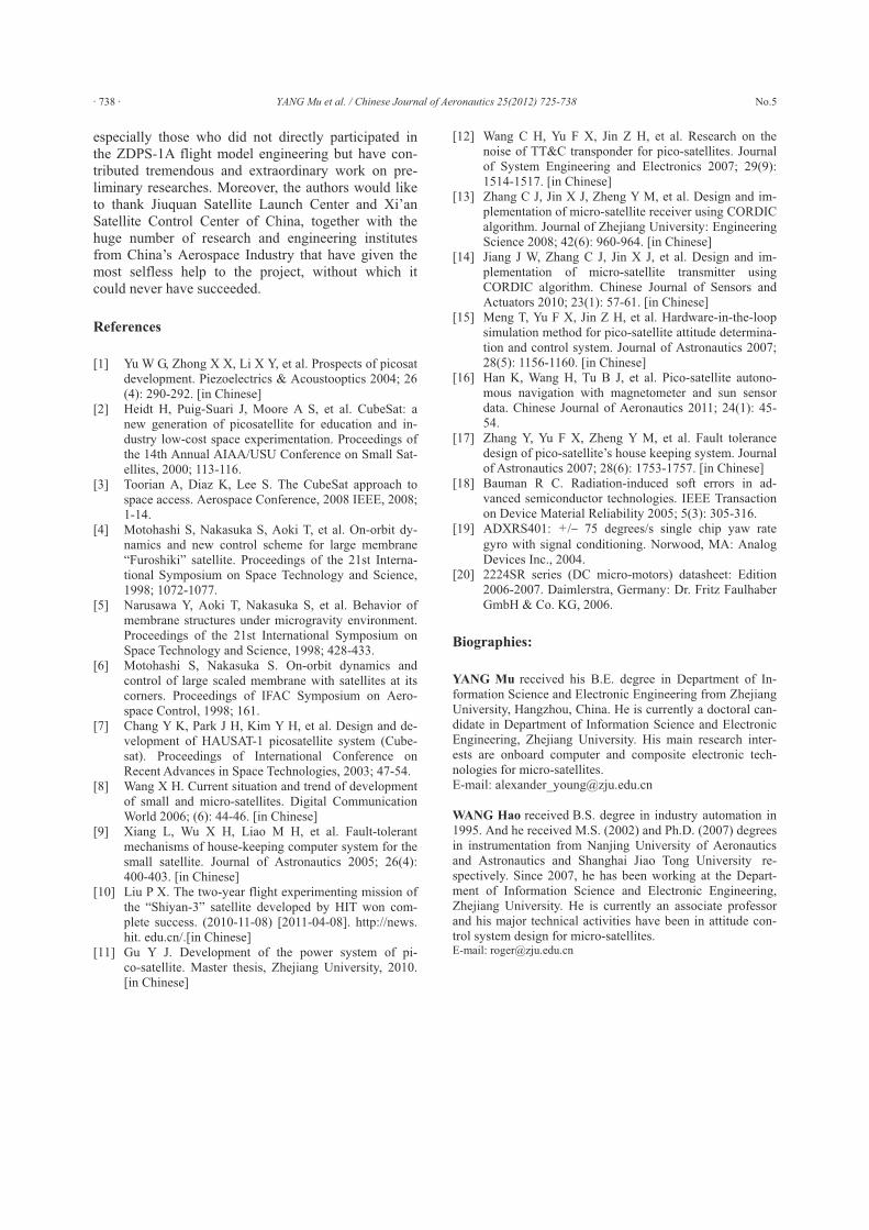
6.2. Tri-axial stabilizing attitude control
Afterwards, the angular velocities were further re-
duced via de-tumbling for both flight models, with the
absolute values of the rolling and yaw velocities re-
duced to smaller than 0.01 (°)/s, and that of the pitch-
ing velocity smaller than 0.06 (°)/s. As the flight mod-
els spun slowly into the attitudes with the absolute val-
ues of the rolling and yaw angles smaller than 5°, and
that of the pitching angle smaller than 45°, the prerequi-
sites for the tri-axial stabilizing attitude control were met
for both of the flight models respectively. The changes
in the attitude angles and angular velocity components
of ZDPS-1A02 during the tri-axial stabilizing control
are shown in Figs. 13-14 respectively. It can be observed
that once the stabilizing control mode was initiated, the
absolute values of all three attitude angles quickly con-
verged to and were mainly restrained within 5° with
slow changes, and the angular velocity remained around
zero, indicating not only that its Earth-pointing attitude
was established and maintained, but the kinetic distur-
bances on orbit were also countered. The establishment
of such an attitude could be further verified by the pano-
ramic picture in Fig. 11(b), which was taken by the
flight model then. One exception was that between
21:14 and 21:38, the rolling and yaw angles stayed
constant while the pitching angle fluctuated drastically.
This was because the flight model was in the eclipse
then, and the unavailability of the Sun vector left those
two attitude angles unattainable. Also notably, the
pitching angle and velocity significantly increased
during the transition from under the sunlight to the
eclipse. An analysis suggests that during this period,
the accuracy and credibility of the pitching angle cal-
culation deteriorated significantly, since the output of
the differential Sun sensor did not follow the same
model as that under the sunlight, and the issue was not
considered of in the design.
Fig. 13 Attitude angles of ZDPS-1A02 during tri-axial stabilizing control.
Fig. 14 Angular velocity components of ZDPS-1A02 during tri-axial stabilizing control.

No.5 YANG Mu et al. / Chinese Journal of Aeronautics 25(2012) 725-738 · 737 ·
6.3. Fly-wheel failure
However, neither flight model managed to perform the stabilizing control again. Instead, they only kept doing the de-tumbling work. The main reason for this was that the flywheels on both of the flight models failed on the second day on orbit. This made the satel-lite bodies lose the relative stabilities in the pitching axes provided by the conservation of gyro axes of them. Such a circumstance was out of the capability of the stabilizing control algorithm, but could still be han-dled by the de-tumbling scheme.
The failure of the flywheels was caused by axial overloads on their electrically-driven motors. Each motor carried a mass block with mass of approxi-mately 40 g on its rotor to provide a sufficient angular momentum. During the launch phase, the acceleration and vibration of the vehicle caused a significant “overweight” of the blocks (gravity up to approx- imately 3.1 N), which was far beyond the axial load capacities (0.2 N) [20] of the motors. Posterior ground simulation via vibration tests in different magnitudes for flywheels with different wearing levels showed that such an overweight would significantly shorten the life expectancies of the motors, and reproduced the failure. In Phase I of the simulation, a group of two flywheels have gone through a dynamic aging period of over nine months, and a group of two completely new ones went through vibrations that actually resem-bled the magnitude of the stress during the launch. While for Phase II, two similar groups went through vibrations that imposed three times of the stresses. Af-ter Phase I, the aged flywheels spun with abnormally slow speed before stopping approximately two days later, absorbing currents of approximately 0.45 A each, whilst the new ones saw no such failures until about one month later. Meanwhile, after Phase II, the aged flywheels failed (stopped spinning completely) right away, while the new ones did in approximately one week. Such a result is in consistency with what hap-pened two days after the launch for both of the flight models since both flywheels onboard of them had gone through the same dynamic aging period as the first groups before the launch. Note that the reasons why the flywheels of the flight models did not fail during and after the acceptance vibration tests were that the tests brought along vibrations with significantly lower magnitude than the actual launch phase in case of col-lateral damages, and that the flywheels were not as aged then as when they failed on orbit. Nevertheless, except the flywheels, all other parts including the backup ones of the ADCS worked properly on both the flight models throughout the space flight mission.
7. Conclusions
The ZDPS-1A pico-satellites are the first satellites in China within the 1-10 kg mass range. They are de-
signed to be “larger but stronger” than most of their peer satellites so as to bear a better promise for real applications.
All three goals of the satellites’ space flight mission that imposed various harsh environmental stresses on them have been reached with encouraging outcomes. First, the functionality and performance of the flight models are tested on orbit and validated to be mostly normal and in consistency with design and ground tests. Specifically, the EPS subsystems are proven suf-ficient with considerable margins. The TTC subsys-tems provide stable functions and performances. The CEU subsystems not only perform accurate executions of commands, but successfully detect and repair a sat-ellite-ground telecom malfunction that is out of the reach of ground operations. These three subsystems, as the “minimum system”, thus managed to sustain the most crucial survivability of the satellites. The OBC subsystems handled all the onboard data and control streams properly. The ThC subsystems are able to pro-vide other systems with comfortable environmental temperatures with still significant margins. While the MS subsystems hold enough strengths for the struc-tural and electronic interconnections among all the subsystems to survive the enormous dynamics during the launch. Second, all the experimented miniaturized parts, including the MEMS accelerometers and gyro-scopes, the in-house-developed panoramic CMOS camera, and the tri-junction Ga-As solar cells, are found to have functioned and performed as expected in space. Third, the ADCS are verified to be able to es-tablish the tri-axial stabilized attitudes with an Earth-pointing precision of 5° under the sunlight, or keep the angular velocities of spinning under 0.2 (°)/s in eclipses for the satellites. What is more, as the satel-lites have worked properly since the launch (in Sep-tember 2010) and until now (August 2011), they have had their on-orbit life expectancy of three months well prolonged. Nevertheless, only a few abnormalities and flaws are observed. Their causes are traced and prone to be mitigated on the succeeding pico-satellite models, while their consequences are recovered or tackled.
In all, the design concept and the engineering proc-ess are effective and sufficient in allowing the ZDPS-1A pico-satellites the desired functionality, per-formance, and space environmental adaption in the launch procedure and the LEO space environment. In the foreseeable future, the platform together with the design concept and the engineering process of the ZDPS-1A pico-satellites are expected to be applied to more complicated real space applications.
Acknowledgement
The authors would like to express their most sincere gratitude towards all the teachers, researchers, engi-neers and students involved in the pico-satellite re-search and engineering project of Zhejiang University,
· 738 · YANG Mu et al. / Chinese Journal of Aeronautics 25(2012) 725-738 No.5
especially those who did not directly participated in the ZDPS-1A flight model engineering but have con-tributed tremendous and extraordinary work on pre-liminary researches. Moreover, the authors would like to thank Jiuquan Satellite Launch Center and Xi’an Satellite Control Center of China, together with the huge number of research and engineering institutes from China’s Aerospace Industry that have given the most selfless help to the project, without which it could never have succeeded.
References
[1] Yu W G, Zhong X X, Li X Y, et al. Prospects of picosat development. Piezoelectrics & Acoustooptics 2004; 26 (4): 290-292. [in Chinese]
[2] Heidt H, Puig-Suari J, Moore A S, et al. CubeSat: a new generation of picosatellite for education and in-dustry low-cost space experimentation. Proceedings of the 14th Annual AIAA/USU Conference on Small Sat-ellites, 2000; 113-116.
[3] Toorian A, Diaz K, Lee S. The CubeSat approach to space access. Aerospace Conference, 2008 IEEE, 2008; 1-14.
[4] Motohashi S, Nakasuka S, Aoki T, et al. On-orbit dy-namics and new control scheme for large membrane “Furoshiki” satellite. Proceedings of the 21st Interna-tional Symposium on Space Technology and Science, 1998; 1072-1077.
[5] Narusawa Y, Aoki T, Nakasuka S, et al. Behavior of membrane structures under microgravity environment. Proceedings of the 21st International Symposium on Space Technology and Science, 1998; 428-433.
[6] Motohashi S, Nakasuka S. On-orbit dynamics and control of large scaled membrane with satellites at its corners. Proceedings of IFAC Symposium on Aero-space Control, 1998; 161.
[7] Chang Y K, Park J H, Kim Y H, et al. Design and de-velopment of HAUSAT-1 picosatellite system (Cube-sat). Proceedings of International Conference on Recent Advances in Space Technologies, 2003; 47-54.
[8] Wang X H. Current situation and trend of development of small and micro-satellites. Digital Communication World 2006; (6): 44-46. [in Chinese]
[9] Xiang L, Wu X H, Liao M H, et al. Fault-tolerant mechanisms of house-keeping computer system for the small satellite. Journal of Astronautics 2005; 26(4): 400-403. [in Chinese]
[10] Liu P X. The two-year flight experimenting mission of the “Shiyan-3” satellite developed by HIT won com-plete success. (2010-11-08) [2011-04-08]. http://news. hit. edu.cn/.[in Chinese]
[11] Gu Y J. Development of the power system of pi-co-satellite. Master thesis, Zhejiang University, 2010. [in Chinese]
[12] Wang C H, Yu F X, Jin Z H, et al. Research on the noise of TT&C transponder for pico-satellites. Journal of System Engineering and Electronics 2007; 29(9): 1514-1517. [in Chinese]
[13] Zhang C J, Jin X J, Zheng Y M, et al. Design and im-plementation of micro-satellite receiver using CORDIC algorithm. Journal of Zhejiang University: Engineering Science 2008; 42(6): 960-964. [in Chinese]
[14] Jiang J W, Zhang C J, Jin X J, et al. Design and im-plementation of micro-satellite transmitter using CORDIC algorithm. Chinese Journal of Sensors and Actuators 2010; 23(1): 57-61. [in Chinese]
[15] Meng T, Yu F X, Jin Z H, et al. Hardware-in-the-loop simulation method for pico-satellite attitude determina-tion and control system. Journal of Astronautics 2007; 28(5): 1156-1160. [in Chinese]
[16] Han K, Wang H, Tu B J, et al. Pico-satellite autono-mous navigation with magnetometer and sun sensor data. Chinese Journal of Aeronautics 2011; 24(1): 45- 54.
[17] Zhang Y, Yu F X, Zheng Y M, et al. Fault tolerance design of pico-satellite’s house keeping system. Journal of Astronautics 2007; 28(6): 1753-1757. [in Chinese]
[18] Bauman R C. Radiation-induced soft errors in ad-vanced semiconductor technologies. IEEE Transaction on Device Material Reliability 2005; 5(3): 305-316.
[19] ADXRS401: +/� 75 degrees/s single chip yaw rate
gyro with signal conditioning. Norwood, MA: Analog Devices Inc., 2004.
[20] 2224SR series (DC micro-motors) datasheet: Edition 2006-2007. Daimlerstra, Germany: Dr. Fritz Faulhaber GmbH & Co. KG, 2006.
Biographies:
YANG Mu received his B.E. degree in Department of In-formation Science and Electronic Engineering from Zhejiang University, Hangzhou, China. He is currently a doctoral can-didate in Department of Information Science and Electronic Engineering, Zhejiang University. His main research inter-ests are onboard computer and composite electronic tech-nologies for micro-satellites. E-mail: [email protected] WANG Hao received B.S. degree in industry automation in 1995. And he received M.S. (2002) and Ph.D. (2007) degrees in instrumentation from Nanjing University of Aeronautics and Astronautics and Shanghai Jiao Tong University re-spectively. Since 2007, he has been working at the Depart-ment of Information Science and Electronic Engineering, Zhejiang University. He is currently an associate professor and his major technical activities have been in attitude con-trol system design for micro-satellites. E-mail: [email protected]