space acceleration measurement systems (sams) agreement ... · space acceleration measurement...
TRANSCRIPT

SAMS-INT-001 Rev D
Space Acceleration Measurement Systems (SAMS)
Agreement and Interface Definition Document (AIDD) for ISS
October, 2004
Prepared For: National Aeronautics and Space AdministrationJohn H. Glenn Research Center at Lewis Field Microgravity Science Division Cleveland, Ohio 44135
Prepared By: ZIN Technologies, Incorporated 3000 Aerospace Parkway Brook Park, Ohio 44142 Under Contract NAS3-99154, 60005-DO-061

SAMS-INT-001 Rev D
ii
Approvals
Prepared by: /s/ Judy A. Anthony Date: 04-28-03
Judith A. Anthony ZIN Technologies, Inc. SAMS Integration Engineer
Reviewed by: /s/ Helen C. Brown Date: 04-28-03
Helen C. Brown ZIN Technologies, Inc. SAMS Integration Lead
Reviewed by: /s/ Natalie Goldin Date: 04-29-03
Natalie Goldin ZIN Technologies, Inc ZIN Safety Engineer
Approved by: /s/ Raymond K. Pavlik Date: 04-29-03 Raymond K. Pavlik
ZIN Technologies, Inc. SAMS Project Lead
Concurred by: /s/ Kevin M. McPherson Date: 05-27-03 Kevin M. McPherson
NASA GRC PIMS Project Manager
Accepted by: /s/ William M. Foster II Date: 05-22-03
William M. Foster, II NASA GRC SAMS Project Manager
SAMS-INT-001 Rev D
iii
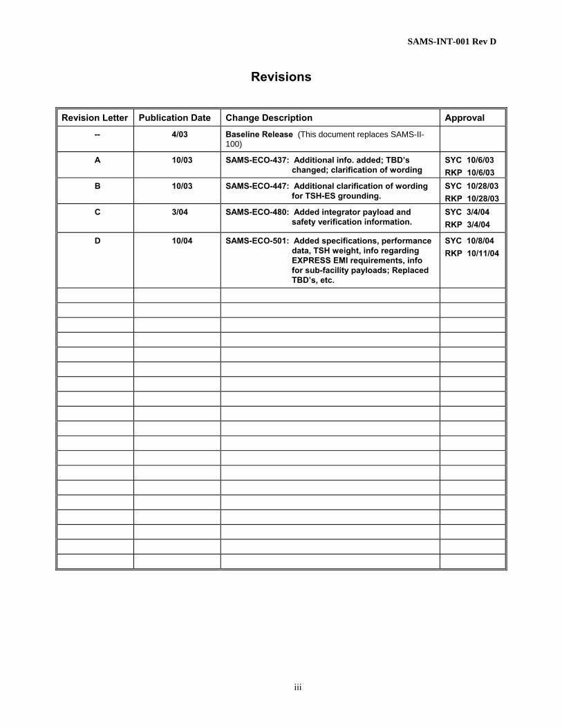
Revisions
Revision Letter Publication Date Change Description Approval
-- 4/03 Baseline Release (This document replaces SAMS-II-100)
A 10/03 SAMS-ECO-437: Additional info. added; TBD’s changed; clarification of wording
SYC 10/6/03 RKP 10/6/03
B 10/03 SAMS-ECO-447: Additional clarification of wording for TSH-ES grounding.
SYC 10/28/03 RKP 10/28/03
C 3/04 SAMS-ECO-480: Added integrator payload and safety verification information.
SYC 3/4/04 RKP 3/4/04
D 10/04 SAMS-ECO-501: Added specifications, performance data, TSH weight, info regarding EXPRESS EMI requirements, info for sub-facility payloads; Replaced TBD’s, etc.
SYC 10/8/04 RKP 10/11/04
SAMS-INT-001 Rev D
iv
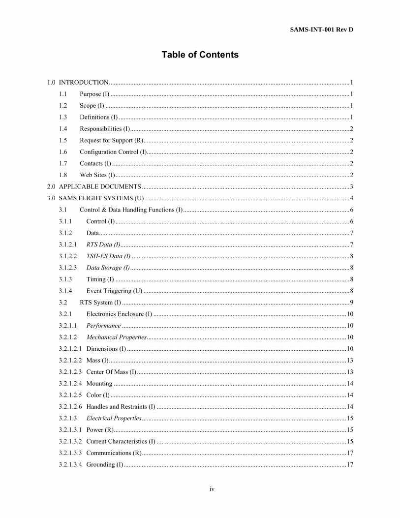
Table of Contents
1.0 INTRODUCTION..................................................................................................................................................1 1.1 Purpose (I) .................................................................................................................................................1 1.2 Scope (I) ....................................................................................................................................................1 1.3 Definitions (I) ............................................................................................................................................1 1.4 Responsibilities (I).....................................................................................................................................2 1.5 Request for Support (R).............................................................................................................................2 1.6 Configuration Control (I)...........................................................................................................................2 1.7 Contacts (I) ................................................................................................................................................2 1.8 Web Sites (I)..............................................................................................................................................2
2.0 APPLICABLE DOCUMENTS..............................................................................................................................3 3.0 SAMS FLIGHT SYSTEMS (U) ............................................................................................................................4
3.1 Control & Data Handling Functions (I).....................................................................................................6 3.1.1 Control (I) ..............................................................................................................................................6 3.1.2 Data........................................................................................................................................................7 3.1.2.1 RTS Data (I)...........................................................................................................................................7 3.1.2.2 TSH-ES Data (I) ....................................................................................................................................8 3.1.2.3 Data Storage (I).....................................................................................................................................8 3.1.3 Timing (I) ..............................................................................................................................................8 3.1.4 Event Triggering (U) .............................................................................................................................8 3.2 RTS System (I) ..........................................................................................................................................9 3.2.1 Electronics Enclosure (I) .....................................................................................................................10 3.2.1.1 Performance ........................................................................................................................................10 3.2.1.2 Mechanical Properties.........................................................................................................................10 3.2.1.2.1 Dimensions (I) .....................................................................................................................................10 3.2.1.2.2 Mass (I)................................................................................................................................................13 3.2.1.2.3 Center Of Mass (I) ...............................................................................................................................13 3.2.1.2.4 Mounting .............................................................................................................................................14 3.2.1.2.5 Color (I) ...............................................................................................................................................14 3.2.1.2.6 Handles and Restraints (I) ...................................................................................................................14 3.2.1.3 Electrical Properties............................................................................................................................15 3.2.1.3.1 Power (R).............................................................................................................................................15 3.2.1.3.2 Current Characteristics (I) ...................................................................................................................15 3.2.1.3.3 Communications (R)............................................................................................................................17 3.2.1.3.4 Grounding (I).......................................................................................................................................17

SAMS-INT-001 Rev D
v
3.2.1.3.5 Bonding (R) .........................................................................................................................................17 3.2.1.3.6 RTS Cables ..........................................................................................................................................17 3.2.1.3.7 Electromagnetic Interference (I) ..........................................................................................................18 3.2.1.4 Software ...............................................................................................................................................19 3.2.1.4.1 Facility Health & Status (U) ................................................................................................................19 3.2.1.5 Environment.........................................................................................................................................19 3.2.1.5.1 Thermal (R) .........................................................................................................................................19 3.2.1.5.2 Pressure (I)...........................................................................................................................................19 3.2.5.1.3 Humidity (I) .........................................................................................................................................20 3.2.1.5.4 Loads (R) .............................................................................................................................................20 3.2.1.5.5 Repressurization/Depressurization (I) .................................................................................................20 3.2.1.5.6 Ground Storage Environment (I) .........................................................................................................20 3.2.1.6 Fire Detection & Suppression (I) ........................................................................................................20 3.2.1.7 Verification ..........................................................................................................................................21 3.2.1.7.1 ISS/Performance Verification (I).........................................................................................................21 3.2.1.7.2 Safety Verification (I)..........................................................................................................................21 3.2.2 Sensor Enclosure (SE) (I) ....................................................................................................................22 3.2.2.1 Performance (I) ...................................................................................................................................22 3.2.2.2 Mechanical Properties.........................................................................................................................23 3.2.2.2.1 Dimensions (I) .....................................................................................................................................23 3.2.2.2.2 Mass (I)................................................................................................................................................23 3.2.2.2.3 Center Of Mass (I) ...............................................................................................................................23 3.2.2.2.4 Mounting .............................................................................................................................................24 3.2.2.2.5 Color (I) ...............................................................................................................................................25 3.2.2.3 Electrical Properties.............................................................................................................................25 3.2.2.3.1 Power (I) ..............................................................................................................................................25 3.2.2.3.2 Current Characteristics (I) ...................................................................................................................26 3.2.2.3.3 Communications (I) .............................................................................................................................26 3.2.2.3.4 Grounding (I).......................................................................................................................................26 3.2.2.3.5 Bonding (R) .........................................................................................................................................26 3.2.2.3.6 RTS Cable (U) .....................................................................................................................................26 3.2.2.3.7 Electromagnetic Interference (I) ..........................................................................................................27 3.2.2.4 Software ...............................................................................................................................................27 3.2.2.4.1 SAMS Facility Health & Status (U) ....................................................................................................27 3.2.2.5 Environment.........................................................................................................................................28 3.2.2.5.1 Thermal (R) .........................................................................................................................................28

SAMS-INT-001 Rev D
vi
3.2.2.5.2 Pressure (I)...........................................................................................................................................28 3.2.2.5.3 Humidity (I) .........................................................................................................................................28 3.2.2.5.4 Loads (R) .............................................................................................................................................28 3.2.2.5.5 Repressurization/Depressurization (I) .................................................................................................28 3.2.2.5.6 Ground Storage Environment (I) .........................................................................................................29 3.2.2.6 Fire Detection & Suppression (I) ........................................................................................................29 3.2.2.7 Verification ..........................................................................................................................................29 3.2.2.7.1 ISS/Performance Verification (I).........................................................................................................29 3.2.2.7.2 Safety Verification (I)..........................................................................................................................29 3.3 Triaxial Sensor Head-Ethernet Standalone (TSH-ES).............................................................................30 3.3.1 Performance (I)....................................................................................................................................30 3.3.2 Mechanical Properties .........................................................................................................................31 3.3.2.1 Dimensions (I) .....................................................................................................................................31 3.3.2.2 Mass (I)................................................................................................................................................33 3.3.2.3 Center Of Mass (I) ...............................................................................................................................33 3.3.2.4 Mounting..............................................................................................................................................34 3.3.2.4.1 Mounting Structure (G) .......................................................................................................................34 3.3.2.4.2 Attachment (R) ....................................................................................................................................34 3.3.2.4.3 Mounting Location (R) ........................................................................................................................34 3.3.2.5 Color (I) ...............................................................................................................................................35 3.3.3 Electrical Properties.............................................................................................................................35 3.3.3.1 Power (R).............................................................................................................................................35 3.3.3.2 Current Characteristics (I) ..................................................................................................................35 3.3.3.3 Communications (R) ............................................................................................................................37 3.3.3.4 Grounding (I).......................................................................................................................................37 3.3.3.5 Bonding (R)..........................................................................................................................................37 3.3.3.6 TSH-ES Cable (U) ...............................................................................................................................38 3.3.3.6.1 Supplied by SAMS (S, R)....................................................................................................................38 3.3.3.6.2 Supplied by User (R) ...........................................................................................................................38 3.3.3.6.3 Cable Routing (R)................................................................................................................................40 3.3.3.7 Electromagnetic Interference (I) .........................................................................................................40 3.3.3.8 Load Impedance (I) .............................................................................................................................40 3.3.3.9 Radiation ..................................................................................................................................................41 3.3.4 Software...............................................................................................................................................41 3.3.4.1 Facility Health & Status (U)................................................................................................................41 3.3.5 Environment ........................................................................................................................................41

SAMS-INT-001 Rev D
vii
3.3.5.1 Thermal (R)..........................................................................................................................................41 3.3.5.2 Pressure (I) ..........................................................................................................................................41 3.3.5.3 Humidity (I) .........................................................................................................................................42 3.3.5.4 Loads (R) .............................................................................................................................................42 3.3.5.5 Repressurization/Depressurization (I).................................................................................................42 3.3.5.6 Ground Storage Environment (I).........................................................................................................42 3.3.6 Fire Detection & Suppression (I).........................................................................................................42 3.3.7 Verification..........................................................................................................................................42 3.3.7.1 ISS/Performance Verification (I) .........................................................................................................42 3.3.7.2 Safety Verification (I)...........................................................................................................................43
4.0 ANCILLARY MOUNTING HARDWARE ........................................................................................................44 4.1 Mounting Plates (U) ................................................................................................................................44 4.1.1 Supplied by SAMS (S, R)....................................................................................................................44 4.1.2 Supplied by User (R) ...........................................................................................................................44
5.0 INTEGRATION & OPERATIONS.....................................................................................................................45 5.1 Integration................................................................................................................................................45 5.1.1 Coordinates & Alignment (R)..............................................................................................................45 5.1.2 Testing .................................................................................................................................................45 5.1.2.1 Support of User Development Testing (U) ..........................................................................................45 5.1.2.2 SAMS Flight Verification Testing (I) ...................................................................................................45 5.1.2.3 SAMS & User Integrated Flight Verification Testing (R)....................................................................45 5.1.2.4 KSC Flight Verification Testing (R) ....................................................................................................46 5.1.3 Hardware Turnover (U) .......................................................................................................................46 5.1.4 Acceptance Data Package (S) ..............................................................................................................46 5.1.5 Hardware Shipping (R)........................................................................................................................46 5.1.6 Stowage Launch & Landing (R)..........................................................................................................46 5.1.7 Crew Procedures (U) ...........................................................................................................................47 5.1.8 Crew Training (S, U) ...........................................................................................................................47 5.1.9 Mission Planning (R, U) ......................................................................................................................47 5.1.10 Labels (R) ............................................................................................................................................47 5.1.11 Part Numbers (I) ..................................................................................................................................48 5.2 Flight Operational Resources ..................................................................................................................48 5.2.1 Facility and Subrack Payload Interactions (I)......................................................................................48 5.2.2 Resource Allocation (I)........................................................................................................................48 5.2.2.1 Power (R).............................................................................................................................................48 5.2.2.2 Thermal (I)...........................................................................................................................................48

SAMS-INT-001 Rev D
viii
5.2.2.3 Mass (U) ..............................................................................................................................................48 5.2.2.4 Command and Data Handling (S) .......................................................................................................49 5.2.2.5 Crew Time (R,S)...................................................................................................................................49 5.2.2.6 On-Orbit Stowage (R, S)......................................................................................................................49 5.2.2.7 Return Flight (U) .................................................................................................................................49 5.2.3 Sensor Head Configuration..................................................................................................................49 5.2.3.1 Initial Configuration (S) ......................................................................................................................49 5.2.3.2 SAMS Power On (I) .............................................................................................................................49 5.2.3.3 Reconfiguration (U).............................................................................................................................49 5.2.4 Calibration Requirements (I) ...............................................................................................................50 5.3 Ground Operations ..................................................................................................................................50 5.3.1 Data Flow (I) .......................................................................................................................................50 5.3.2 On Console Support (I)........................................................................................................................50 5.3.3 Precedence of Users (I)........................................................................................................................50
APPENDIX A – SAMS REQUEST FORM .................................................................................................A-1 APPENDIX B - RTS RANDOM VIBRATION PARAMETERS ................................................................B-1 APPENDIX C – INTEGRATOR SAFETY VERIFICATIONS ...................................................................C-1 APPENDIX D – PROCEDURE HISTORY / LOG SHEET.........................................................................D-1 APPENDIX E – RTS AND TSH PERFORMANCE GRAPH...................................................................... E-1

SAMS-INT-001 Rev D
ix
List of Figures
Figure 1 – SAMS System Philosophy – ISS Implementation .......................................................................................5 Figure 2 - SAMS Interim Control Unit .........................................................................................................................6 Figure 3 - SAMS Electronics Enclosure and Sensor Enclosure ....................................................................................9 Figure 4 – Remote Triaxial Sensor – Electronics Enclosure .......................................................................................10 Figure 5 - Top View of EE With Straight Backshell...................................................................................................11 Figure 6 – RTS Cable 90 Degree Backshell................................................................................................................11 Figure 7 – Front View of EE .......................................................................................................................................12 Figure 8 - Side View of EE .........................................................................................................................................12 Figure 9 - EE Center of Mass Reference.....................................................................................................................13 Figure 10 – RTS Inrush Current Characteristics .........................................................................................................16 Figure 11 – RTS Steady State Current Characteristics................................................................................................16 Figure 12 – EE Power Cable .......................................................................................................................................18 Figure 13 - Remote Triaxial Sensor - Sensor Enclosure .............................................................................................22 Figure 14 - Sensor Enclosure and Base .......................................................................................................................23 Figure 15 - SE Center of Mass Reference ...................................................................................................................24 Figure 16 - Examples of SE Interfacing ......................................................................................................................27 Figure 17 – Triaxial Sensor Head—Ethernet Standalone............................................................................................30 Figure 18 - Sensor Enclosure and Base .......................................................................................................................31 Figure 19 – TSH-ES Dimensions with Straight Backshell..........................................................................................32 Figure 20 – TSH-ES Dimensions with a 90 degree Backshell ....................................................................................32 Figure 21 – TSH-ES Center of Mass Reference..........................................................................................................33 Figure 22 – TSH-ES Inrush Current Characteristics ...................................................................................................36 Figure 23 – TSH-ES Steady State Current Characteristics..........................................................................................36 Figure 24 - Examples of TSH-ES Interfacing .............................................................................................................38 Figure 25 – TSH-ES Cable Schematic ........................................................................................................................39

SAMS-INT-001 Rev D
x
List of Tables
Table 1 – Vibratory Sensor Frequency Ranges .............................................................................................................7 Table 2 - EE Center of Mass Example ........................................................................................................................13 Table 3 - Power Cable Pinout......................................................................................................................................17 Table 4 - Data Cable Pinout ........................................................................................................................................18 Table 5 - Data Cable Connector ..................................................................................................................................18 Table 6 – EE Baseplate Temperature States................................................................................................................19 Table 7 – EE Ground Storage Restrictions..................................................................................................................20 Table 8 - SE Center of Mass Example.........................................................................................................................23 Table 9 – SE Ground Storage Restrictions..................................................................................................................29 Table 10 – TSH-ES Center of Mass Example .............................................................................................................33 Table 11 – TSH-ES Cable, SAMS Connector Pinout .................................................................................................38 Table 12 – TSH-ES Ground Storage Restrictions .......................................................................................................42 Table 13 - Standard Part Numbers ..............................................................................................................................48 Table 14 - Maximum Allowable EE Random Vibration Levels ...............................................................................B-2 Table 15 - Maximum Allowable SE Random Levels................................................................................................B-2 Table 16 - Maximum Allowable TSH-ES Random Levels .......................................................................................B-2 Table 17 - Integrator EE Safety Verifications ...........................................................................................................C-2 Table 18 - Integrator SE Safety Verifications ...........................................................................................................C-4 Table 19 - TSH-ES Safety Verifications passed to the Integrator.............................................................................C-6

SAMS-INT-001 Rev D
xi
Acronyms & Abbreviations
ADP Acceptance Data Package AIDD Agreement and Interface Definition Document C Celsius CoC Certificate of Conformance CoFR Certificate of Flight Readiness dc direct current ECW Emergency Caution and Warning EE Electronics Enclosure ES Ethernet Standalone EXPRESS EXpedite the PRocessing of Experiments to Space Station FCF Fluids Combustion Facility GOE Ground Operations Equipment GRC Glenn Research Center ICAD Interface Control and Agreement Document ICU Interim Control Unit IPLAT ISS Payload Label Approval Team ISS International Space Station ISIS International Subrack Interface Standards ISPR International Standard Payload Rack iURC Interim Users Requirements Collection IVA Intra Vehicular Activity JSC Johnson Space Center LOS Loss of Signal mA milliampere MOU Memorandum of Understanding MSG Microgravity Science Glovebox MSID Measurement Identification NASA National Aeronautics and Space Administration PDL Payload Data Library PI Principal Investigator PIMS PI Microgravity Services POIF Payload Operations Integration Function PODF Payload Operations Data File RICO Realtime Information Control Officer RTS Remote Triaxial Sensor SAMS Space Acceleration Measurement Systems SAMS-II Space Acceleration Measurement System-II (hardware specific) SE Sensor Enclosure SRD Science Requirements Document

SAMS-INT-001 Rev D
xii
TBD To Be Determined TSH Triaxial Sensor Head WBS Work Breakdown Structure
SAMS-INT-001 Rev D
1
1.0 INTRODUCTION
1.1 Purpose (I)
This document, the Agreement and Interface Definition Document (AIDD), defines the physical and operational requirements for using SAMS acceleration systems available for use on the International Space Station (ISS). The AIDD is the base document for the creation of the Interface Control and Agreement Document (ICAD). The ICAD defines all of the applicable AIDD requirements and interfaces as well as any user unique requirements and negotiated agreements. An ICAD will be created for each user. For subfacility payloads, a separate memo that is associated with the facility ICAD will be created with any unique requirements and negotiated agreements between SAMS and the subfacility payload.
1.2 Scope (I)
This AIDD is to be used for all SAMS ISS mission users when the SAMS system is a subsystem to the user’s hardware.
This AIDD is divided into multiple sections; Section 3.0 discusses SAMS hardware systems, Section 4.0 discusses SAMS ancillary mounting hardware, and Section 5.0 discusses SAMS Integration/Operations.
1.3 Definitions (I)
Subsystem – A system that is part of the payload or facility.
User – identified as the agency, program, project, or other entity accepting and integrating the SAMS system into the payload or facility.
Payload – identified as the experiment hardware, whether in a rack, locker, or drawer, that will be onboard the ISS.
Section identification – Each section in this document is classified so that requirements and deliverables can be easily identified. The classifications are defined here. Some sections may have more than one classification. A “shall” statement is used for all requirements.
G – The section contains guidelines for the use of the SAMS subsystems. No deliverable will be tracked.
I – The section has information of the SAMS subsystems, process, and/or the project. No deliverable will be tracked.
R – The section contains a user requirement/deliverable that shall be tracked to closure. It may also include information.
S – The section contains a SAMS requirement/deliverable that shall be tracked to closure. It may also include information.
U – The section contains user specific items. These sections require a note in the ICAD to identify the specific use. A deliverable may be tracked based on the agreement.

SAMS-INT-001 Rev D
2
1.4 Responsibilities (I)
SAMS will create and maintain the user specific ICAD. SAMS will track all deliverables defined in the ICAD to closure. SAMS will provide deliverables per the negotiated ICAD.
The user will provide information to develop the ICAD. The user will provide deliverables per the negotiated ICAD. The deliverables may include such items as drawings, analyses, test data results, emails, Certificates of Conformance (CoC), etc. Note: CoCs replace actual test/analysis data by providing a pass/fail summary of the test/analysis performed. They simply state that the verification was successfully/unsuccessfully performed and are signed by the originator.
1.5 Request for Support (R)
The user shall initiate the integration process by requesting acceleration support by completing the form included in Appendix A and emailing/sending it to William Foster (email address included on form, see below for mailing address). An electronic version of this form can be found at http://sams.grc.nasa.gov.
Payloads utilizing SAMS hardware shall identify their acceleration data needs and services by completing the electronic form at http://pims.grc.nasa.gov/html/RequestDataPlots.html. Facilities utilizing SAMS hardware shall complete this electronic form as needed. Requests submitted through this form will be dispositioned by the PIMS Project at the NASA Glenn Research Center.
1.6 Configuration Control (I)
The SAMS Project maintains configuration control of integration verification data per ISS requirements.
This statement is provided for user Certificate of Flight Readiness (CoFR).
1.7 Contacts (I)
William M. Foster II, (216) 433-2368, SAMS Project Manager
NASA Glenn Research Center, Mail Code 77-7
21000 Brookpark Rd., Cleveland, Ohio 44135
Ray Pavlik, (216) 977-0310, SAMS Contractor Lead
NASA Glenn Research Center, Mail Code ZIN
3000 Aerospace Parkway, Brook Park, Ohio 44142 Judy Anthony, (216) 977-0607, SAMS Customer Integration
NASA Glenn Research Center, Mail Code ZIN
3000 Aerospace Parkway, Brook Park, Ohio 44142
1.8 Web Sites (I)
SAMS: http://sams.grc.nasa.gov
PIMS: http://pims.grc.nasa.gov
The most current operational contact information can be found at these web sites.

SAMS-INT-001 Rev D
3
2.0 APPLICABLE DOCUMENTS
The following documents form a part of this document to the extent specified herein. If no date is given, the current revision of the document should be used. In the event of conflict between the project documents referenced and the contents of this document, the contents of this document shall be considered a superseding requirement.
NASA or ISS Documents
NSTS 1700.7B Safety Policy and Requirements for Payloads Using the Space Transportation System, January 1989
NSTS 1700.7B Safety Policy and Requirements for Payloads Using the International Space ISS Addendum Station
NSTS/ISS 18798B Interpretations of NSTS/ISS Payload Safety Requirements
SSP 30237 Space Station Electromagnetic Emission and Susceptibility Requirements
SSP 30238 Space Station Electromagnetic Techniques, General Vol.1; Vol. 2, Requirements and Procedures
SSP 30695 Acceptance Data Package Requirements Specifications
SSP 52000-IDD-ERP EXPRESS Interface Definition Document
SSP 52000-PVP-ERP EXPRESS Payload Verification Plan
SSP 57000 Pressurized Payloads Interface Requirements Document
Project Documents
SAMS-PLN-000 SAMS Project Plan
SAMS-PLN-001 SAMS Configuration Management Plan
SAMS-SPC-001 SAMS System Specifications Document
SAMS-PLN-005 SAMS Verification Plan for TSH-ES
SAMS-II-007 SAMS-II System Verification Plan
SAMS-II-013 SAMS RTS Phase III Flight Safety Compliance Data Package
SAMS-SDP-001 SAMS TSH-ES Phase I/II Flight Safety Compliance Data Package
SAMS-II-200 SAMS Safety Critical Structures Package
SAMS-II-400 SAMS Data & Command Format Definition Document
SAMS-SPC-006 Data & Command Format Definitions: Users Edition
Industry Documents
IEEE 802.3 (ISO/IEC 8802-3) INTERNATIONAL STANDARD

SAMS-INT-001 Rev D
4
3.0 SAMS FLIGHT SYSTEMS (U)
SAMS is a modular system. The system design philosophy is shown in Figure 1. The approach is to maintain a set of sensors that can be used in multiple locations. Control of the system needs to be simple and user friendly so it can be given to a user with minimal training.
As indicated in the figure, there are two types of sensors, quasi-steady and vibratory. The quasi-steady acceleration measurement is made almost continuously. The sensor is mounted close to the center of gravity of the US Laboratory. No system interface is required; the data can be obtained from the Principal Investigator Microgravity Services (PIMS) Project, reference Section 1.5.
On the ISS, the vibratory sensors are distributed to payload users and facility offices to mount to their hardware or near the area of interest. A rack has a frequency of approximately 20 Hz; therefore, a vibratory sensor on the rack would be acceptable for frequencies below 20 Hz. For higher frequency measurement or more localized measurement, the sensors can be mounted on the payload directly.
SAMS provides remote sensor acceleration subsystems for payload use in MSG, on FCF and on EXPRESS Racks. For interested payload users, SAMS can identify each subsystem associated with each rack.
SAMS Project maintains all other system configuration items, such as the ICU, as “facility” hardware, where the SAMS Project is the “facility.”
The user, PIMS and SAMS will negotiate the appropriate sensor system for the user’s application.

SAMS-INT-001 Rev D
5
Figure 1 – SAMS System Philosophy – ISS Implementation
Long path to GRC TSC
Remote Sensors1. Digitizes data2. Compensates data
WEB Interfaces1. Utilize browsers, systems only act as clients2. Constant Interface3. Interface controlled by log in
Quasi-Steady Sensor
(MAMS)
Vibratory Sensors(RTS, TSH-ES)
Interfaces1. Ethernet2. Serial (RS-232)
Control and Data Handling Functions(divided between ICU & Sensors)
1. Controls all sensors2. Acts as a server to users3. Scalable (included in sensor or a multi-processor server)4. Security5. Log on directly6. Diagnostics7. Track usage
ISS Facility Interface
(RIC, Payload MDM)
PayloadSAMS checkout
computerGROUND ONLY
On-board InterfacePresently provided
by ICU
Ground Support for Realtime Control
1. Interface should be consistent with WEB Interface
2. Software converts data to command strings
3. Software interprets downlink and displays
PIMS Acceleration Data Systems for realtime displays, distribution, and
archiving

SAMS-INT-001 Rev D
6
3.1 Control & Data Handling Functions (I)
This section will describe the control and data handling capabilities that SAMS offers to the user for each sensor system. Software interfaces between the user and SAMS will also be discussed.
SAMS collects acceleration data and distributes this data to the science community. There is more than one type of SAMS sensor that measures the acceleration data, each with slightly different characteristics. No matter which SAMS sensor is used, control and data handling is essentially the same for each device. Any differences will be documented in the following sections.
The distributed architecture of SAMS allows many sensors to be deployed at once, each independently collecting acceleration data and sending the data to a main control unit. The distributed sensors do not have to be the same type of sensor. The control unit can handle different types of sensors collecting data at different rates at the same time. The control unit then stores the data on its hard drive and sends the data to PIMS on the ground. PIMS can then distribute the desired data to the user on the ground.
3.1.1 Control (I)
SAMS sensors are designed to be controlled from the ground or from a device connected to the same network as the sensor. Nominally, a sensor is controlled by the ground sending SAMS formatted commands to the control unit (currently, the Interim Control Unit or ICU is performing this function – see Figure 2 below) and the control unit communicating with the desired sensor over the Ethernet using dedicated TCP/IP socket connections. Alternatively, the control unit will also accept commands from a device connected to the same network.
Figure 2 - SAMS Interim Control Unit Users on the ground have two options for sending commands to a particular sensor: 1) Contact the PIMS or SAMS ground operations and have them issue the command or 2) command their onboard experiment to send the desired command to the control unit.
SAMS-INT-001 Rev D
7
SAMS uses TCP/IP socket connections for all communications. Each sensor and the control unit offer a public port to which users can connect. In these cases, SAMS is always the server. Specifics on how to interface with SAMS are described in SAMS-SPC-006.
An experiment will be able to issue basic commands to the sensor units assigned to it. The available commands include starting acceleration data collection, changing the acceleration data’s frequency range, and stopping acceleration data collection. All commands, whether initiated from an onboard experiment or from the ground, will be sent through the control unit via a command socket connection. The control unit will verify the command, send the originator an acknowledgement message, and implement the command. Detail descriptions of command formats can be found in SAMS-SPC-006.
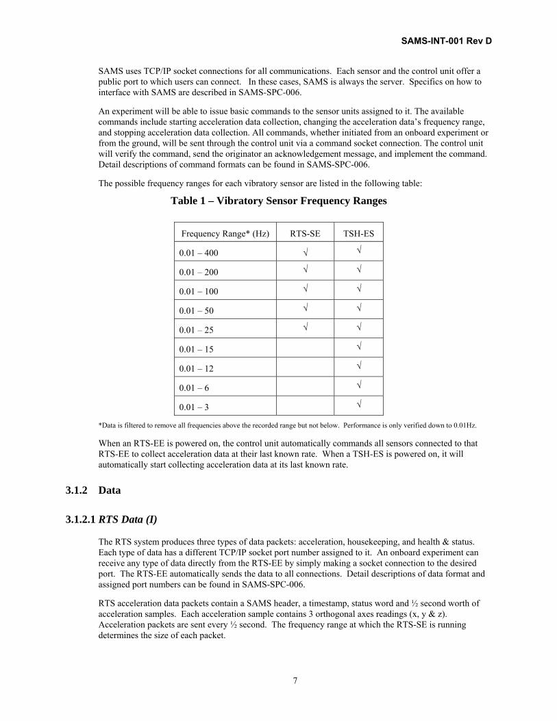
The possible frequency ranges for each vibratory sensor are listed in the following table:
Table 1 – Vibratory Sensor Frequency Ranges
Frequency Range* (Hz) RTS-SE TSH-ES
0.01 – 400 √ √
0.01 – 200 √ √
0.01 – 100 √ √
0.01 – 50 √ √
0.01 – 25 √ √
0.01 – 15 √
0.01 – 12 √
0.01 – 6 √
0.01 – 3 √
*Data is filtered to remove all frequencies above the recorded range but not below. Performance is only verified down to 0.01Hz.
When an RTS-EE is powered on, the control unit automatically commands all sensors connected to that RTS-EE to collect acceleration data at their last known rate. When a TSH-ES is powered on, it will automatically start collecting acceleration data at its last known rate.
3.1.2 Data
3.1.2.1 RTS Data (I)
The RTS system produces three types of data packets: acceleration, housekeeping, and health & status. Each type of data has a different TCP/IP socket port number assigned to it. An onboard experiment can receive any type of data directly from the RTS-EE by simply making a socket connection to the desired port. The RTS-EE automatically sends the data to all connections. Detail descriptions of data format and assigned port numbers can be found in SAMS-SPC-006.
RTS acceleration data packets contain a SAMS header, a timestamp, status word and ½ second worth of acceleration samples. Each acceleration sample contains 3 orthogonal axes readings (x, y & z). Acceleration packets are sent every ½ second. The frequency range at which the RTS-SE is running determines the size of each packet.

SAMS-INT-001 Rev D
8
The health and status packet follows the packet definition defined in SSP 52000-IDD-ERP (EXPRESS formatted H&S packet). This packet contains an EXPRESS header, an Emergency Caution & Warning (ECW) word, a cyclical counter, unit ID and the baseplate temperature of the EE. The ECW word is set to different values that define the status of the EE. When the baseplate temperature rises above its caution limit (typically 42 degrees C), the ECW is set to 0x01 hex signaling the EE is operating hotter than expected. When the baseplate temperature rises above its warning limit (typically 62 degrees C), the ECW is set to 0x052 hex signaling the need for the integrator to cut the power to the EE.
The RTS housekeeping packet contains a SAMS header, unit ID, axes temperatures, baseplate temperature and various internal voltages. This packet is sent to SAMS operations on the ground for monitoring purposes.
Both the health and status and housekeeping packets are generated at a rate of 1 Hz.
3.1.2.2 TSH-ES Data (I)
The TSH-ES produces two types of data packets: acceleration, and housekeeping. Each type of data has a different TCP/IP socket port number assigned to it. An onboard experiment can receive either type of data directly from the TSH-ES by simply making a socket connection to the desired port. The TSH-ES automatically sends the data to all connections. Detail descriptions of data format and assigned port numbers can be found in SAMS-SPC-006.
TSH-ES acceleration data packets contain a SAMS header, a timestamp, status word and 512 acceleration samples. Each acceleration sample contains 3 orthogonal axes readings (x, y & z). The frequency range at which the TSH-ES is running determines the frequency of each packet (acceleration packets are sent as soon as 512 samples have been collected).
The TSH-ES housekeeping packet contains a SAMS header, unit ID, axes temperatures, various internal voltages and digital I/O status. This packet is sent to SAMS operations on the ground for monitoring purposes. Housekeeping packets are generated at a rate of 1 for every acceleration data packet.
3.1.2.3 Data Storage (I)
The control unit can be commanded to store any sensor’s acceleration data or housekeeping data into a separate file that an onboard experiment can access via FTP. All data is temporarily stored on the control unit’s hard drive, but this feature allows an onboard experiment to access a stored data file directly. Specific details on how to command the control unit to store data are defined in SAMS-SPC-006.
3.1.3 Timing (I)
The SAMS control unit obtains its time from the ISS EXPRESS rack in which it is located. All SAMS sensor systems synch their internal clocks to the control unit’s clock by means of the unix protocol xntp. This synchronization requires that the sensor systems are able to communicate with the control unit via the ISS Payload ethernet. The sensor system’s internal clock provides the time stamp for the acceleration, housekeeping and health and status data. The control unit can act as a time server for any onboard experiment running an xntp program.
3.1.4 Event Triggering (U)
The TSH-ES has 3 digital I/O lines (1 input, 1 output, 1 bidirectional) that can be used to trigger onboard experiments. This capability will not be implemented until a user requests this feature.

SAMS-INT-001 Rev D
9
3.2 RTS System (I)
The RTS is an assembly consisting of an Electronics Enclosure (EE) and one or two Sensor Enclosures (SE), all designed for use in the International Space Station environment.
The SEs interface with the EE and the EE interfaces with the control unit. The SE is an acceleration-measuring package made up of acceleration transducers, temperature transducers, and required circuitry for output of digital acceleration data. The EE is a data processing and measurement support package made up of power distribution circuitry for the attached SEs, network interface circuitry, and circuitry to acquire acceleration data from each attached SE. It compensates for temperature and SE bias effects and then transmits the data via the ISS payload ethernet to the control unit. Figure 3 contains a picture of a SAMS RTS EE, two RTS SEs and a SAMS RTS Cable.
Figure 3 - SAMS Electronics Enclosure and Sensor Enclosure

SAMS-INT-001 Rev D
10
3.2.1 Electronics Enclosure (I)
An EE has four electrical connectors that provide interfaces to rack power, rack ethernet network and each of two SEs (via EE channels A and B), as shown in Figure 4. The EE connectors have plastic dust caps for shipping. All cables supplied by the SAMS Project will utilize tethered caps. Accessibility to the EE is needed for on-orbit off-nominal operations such as resetting the power switch (circuit breaker) and replacement of the unit.
Figure 4 – Remote Triaxial Sensor – Electronics Enclosure
3.2.1.1 Performance
The performance of the RTS System is defined by the SE. Reference section 3.2.2.1.
3.2.1.2 Mechanical Properties
3.2.1.2.1 Dimensions (I)
The EE dimensions are 237 mm (9.3 in) in width, 118.8 mm (4.7 in) in height and 230 mm (9.1 in) in length. These dimensions do not include interface cabling with appropriate bend radii. Cable backshells will require additional space. Dimensioned drawings of the EE and interface cabling are shown in Figures 5 through 8.

SAMS-INT-001 Rev D
11
Figure 5 - Top View of EE With Straight Backshell
Figure 6 – RTS Cable 90 Degree Backshell

SAMS-INT-001 Rev D
12
Figure 7 – Front View of EE
Figure 8 - Side View of EE
SAMS-INT-001 Rev D
13
3.2.1.2.2 Mass (I)
The EE has a mass of approximately 5 kg (11 lbs). Individual units may vary slightly, due to parts tolerance. The mass will be provided for a specific unit by the SAMS Project upon request.
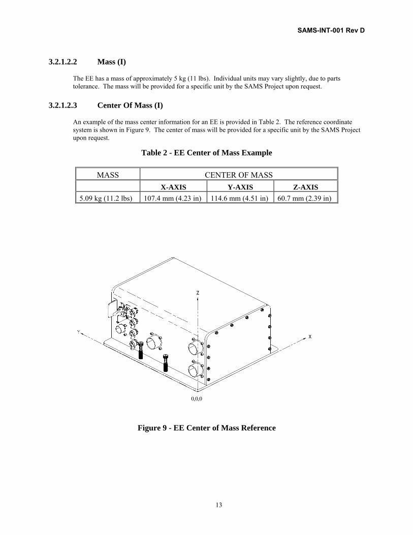
3.2.1.2.3 Center Of Mass (I)
An example of the mass center information for an EE is provided in Table 2. The reference coordinate system is shown in Figure 9. The center of mass will be provided for a specific unit by the SAMS Project upon request.
Table 2 - EE Center of Mass Example
MASS CENTER OF MASS X-AXIS Y-AXIS Z-AXIS 5.09 kg (11.2 lbs) 107.4 mm (4.23 in) 114.6 mm (4.51 in) 60.7 mm (2.39 in)
Figure 9 - EE Center of Mass Reference
0,0,0

SAMS-INT-001 Rev D
14
3.2.1.2.4 Mounting
3.2.1.2.4.1 Attachment (R)
The EE is attached using four integral Tridair CA28080C-3-11HS fully retracting spring loaded captive screw assemblies with nut retainers as shown in Figure 8. The user shall secure the EE utilizing all four of these fasteners to provide a fail-safe condition and ensure a rigid connection between the EE and the facility/payload surface.
Each fastener has a hex socket recess for tool installation. All the tools necessary to perform SAMS hardware mounting are available from the ISS IVA Toolkit. SAMS Figure 5 shows the bolt hole pattern for the EE interface. If further details are needed, SAMS drawing #60005MA12212 (EE Base Detail) can be requested.
The fasteners are sized for cold plate applications (0.688 inch depth of thread); spacers may be required for other applications. Structural analysis of the EE was performed with the four captive fasteners installed into CRES stainless steel inserts with 25 ± 1 in-lbs plus running torque. For the EEs mounted in all EXPRESS racks the torque is 20 ± 1 in-lbs plus running torque. A minimum thread engagement of 0.31 inches is required. Deviations to this mounting scheme require specific review and approval by the SAMS Project.
The user shall provide self-locking nuts/nut plates for EE captive fastener mounting if the fasteners are used for securing hardware during Orbiter launch or landing, and verify this by independent inspection (ref. SAMS-II-013, Hazard Report SAMS-II-RTS-02, Verification 5.1.1). The user shall perform an analysis, test and/or inspection to verify the integrity of the nut/nut plates used for the EE captive fasteners (ref. SAMS-II-013, Hazard Report SAMS-II-RTS-02, Verification 5.2.1).
Details pertaining to the installation of an EE into the user’s hardware shall be defined in the user's ICAD. For all installation and removal operations involving an EE, either prior to launch or on-orbit, the user shall include steps utilizing all four captive fasteners for each EE and applying the proper torque to the captive fasteners (ref. SAMS-II-013, Hazard Report SAMS-II-RTS-02, Verification 4.2.1) and inserting a verifiable inhibit to remove power to the EE (ref. SAMS-II-013, Hazard Report SAMS-II-RTS-04, Verification 2.1).
3.2.1.2.4.2 Mounting Location (R)
When mounting, the EE shall have at least a 1 inch clearance from all surrounding objects. This is to ensure clearance for removal. The mounting location shall be in agreement with all egress requirements.
3.2.1.2.5 Color (I)
The EE is painted with Chemglaze II, A-276 glossy white.
3.2.1.2.6 Handles and Restraints (I)
The EE does not have handles or restraints because it was designed to be mounted in a specific location and not removed during nominal operation. Due to this design, the EE does not meet SSP 57000 requirement 3.12.6.4.1 on handles and restraints.

SAMS-INT-001 Rev D
15
3.2.1.3 Electrical Properties
3.2.1.3.1 Power (R)
The EE shall be powered by 28Vdc from a cable provided by the user (reference section 3.1.1.3.6.1 Power Cable). The EE is functionally verified to an input voltage range of 25 – 29.5Vdc. The average electrical power is approximately 10 watts.
The user shall perform testing to verify that the maximum voltage supplied to the EE is no greater than 32 V (ref. SAMS-II-013, Hazard Report SAMS-II-RTS-04, Verification 1.1.2).
The user shall provide an inhibit, verifiable at the time of insertion, that removes voltage to the EE. The user shall perform testing to demonstrate the functionality and verifiability of this inhibit (ref. SAMS-II-013, Hazard Report SAMS-II-RTS-04, Verification 1.1.1).
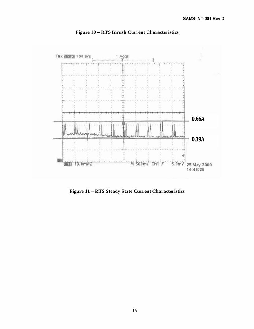
3.2.1.3.2 Current Characteristics (I)
Figure 10 displays the inrush current waveform of an EE supplied with 28+0.1Vdc and with two SEs attached to channel A and channel B. The peak inrush current was designed to be under 15 Vdc, but as seen in Figure 10, is typically measured to be around 10.2 Vdc.
Figure 11 displays the steady state current waveform of an EE supplied with 28+0.1Vdc and with two SEs attached to channel A and channel B. As seen in Figure 11, the steady state current typically varies between 0.39 A and 0.66 A.
2 A/division
SAMS-INT-001 Rev D
16
Figure 10 – RTS Inrush Current Characteristics
0.66A
0.39A
Figure 11 – RTS Steady State Current Characteristics

SAMS-INT-001 Rev D
17
3.2.1.3.3 Communications (R)
The user shall provide the EE with ethernet access to the SAMS control unit. If the EE is located outside of the EXPRESS rack housing the SAMS control unit, then the user shall provide the EE with access to the ISS Payload ethernet network. The ethernet access to the EE shall be via the data cable described in section 3.2.1.3.6.2. The user shall also configure the internal network (including any hubs/bridges) to allow TCP/IP messages between the EE and the SAMS control unit to pass through. The EE interface to the ethernet, including the data cable described in section 3.2.1.3.6.2 Data Cable, shall be IEEE 802.3 (ISO/IEC 8802-3) standard compliant.
3.2.1.3.4 Grounding (I)
The EE meets the grounding requirements of SSP 30240.
3.2.1.3.5 Bonding (R)
The EE meets the bonding requirements of SSP 30245 and NSTS 1700.7B.
The user shall perform a ground-based certification test using EE flight hardware along with the planned on-orbit installation operations, to ensure that there is a bond between the EE and the user's hardware that meets the requirements of SSP 30245 (ref. SAMS-II-013, Hazard Report SAMS-II-RTS-04, Verification 1.4.2).
3.2.1.3.6 RTS Cables
3.2.1.3.6.1 Power Cable (R)
The power cable shall be provided by the user, and shall comply with the pinout as shown in Table 3 and Figure 12. It shall use 20 AWG size wire and be terminated with an MS27467T11F4S connector. The chassis connector on the EE is an MS27656T11F4P connector. If 20 AWG size wire is too small for the user, it is the user’s responsibility to appropriately increase the wire size as per the wire derating requirements of NSTS 18798B, TA-92-038. The user shall verify cable functionality and shall meet the safety and carrier related requirements of the power cable.
Table 3 - Power Cable Pinout
Power Connector Pin Purpose A 28 Vdc B 28 Vdc return C Chassis ground D No connection

SAMS-INT-001 Rev D
18
SOURCE
28 VDCPOWER
A
B
C
28 VDC
28 VDC RTN
CHASSIS GND
D
Figure 12 – EE Power Cable
3.2.1.3.6.2 Data Cable (R)
The user shall supply the ethernet cable for the EE, utilizing the pinout schedule shown below (Table 4). The cable shall be compatible with the IEEE 802.3 standard for ethernet communications. Table 5 specifies the connectors that shall be utilized. The user shall verify cable functionality and shall meet the safety and carrier related requirements of the data cable.
Table 4 - Data Cable Pinout
SAMS GENERATED
SIGNAL SAMS PIN User’s Ethernet Port *
Rx+ F Tx+ Rx- G Tx- Tx+ D Rx+ Tx- E Rx-
* If the user’s ethernet hub does not cross the Rx and Tx lines, the user shall ensure that the SAMS ethernet signals get mapped as defined in table 4 (Rx+ to Tx+, Rx- to Tx-, etc) before it reaches its destination.
Table 5 - Data Cable Connector
EE Chassis Cable Termination
MS27656T13F98P MS27467T13F98S
3.2.1.3.7 Electromagnetic Interference (I)
With a qualification unit, electromagnetic interference was verified per the EXPRESS Rack Interface Definition Document, SSP 52000-IDD-ERP. Electromagnetic interference testing was repeated using a flight unit to verify compliance to MSG Investigation Interface Requirements Document, MSFC-RQMT-2888.

SAMS-INT-001 Rev D
19
With each flight unit, electromagnetic interference emissions testing is completed per SSP 52000-IDD-ERP. This subset of tests will prove workmanship of the unit. User specific requirements can be addressed during this testing on new SAMS hardware.
3.2.1.4 Software
3.2.1.4.1 Facility Health & Status (U)
If the user is a facility, then the user shall inform the SAMS Project of the MSID of any facility functions related to SAMS, such as SAMS power port activity, SAMS ethernet port activity, nearby temperature sensor readings, etc.
3.2.1.5 Environment
3.2.1.5.1 Thermal (R)
Each EE undergoes thermal acceptance testing over an operating temperature range of 0º to 50 °C. The heat dissipation of an EE is approximately 10 watts. The external surface temperature of an EE under nominal operating conditions is typically no more than 2 °C higher than the surface upon which it is mounted. Therefore an EE mounted in crew accessible locations is restricted to an operating thermal environment of 0º to 45°C.
The EE will monitor its internal temperature using data from a temperature sensor mounted on the inside base of the EE. The averaged base temperature is included in both health and status packets generated by the EE (see section 3.1.2.1 RTS Data) and is available to the user. The three temperature states are defined as below in Table 6.
Table 6 – EE Baseplate Temperature States
State Base_temp Ranges (C)
nominal 5 < t < 42
caution 0< t ≤ 5 42 ≤ t < 62
warning t ≤ 0 t ≥ 62
The EE cannot automatically remove power from itself. The SAMS Project requests that the user removes power from the EE when the warning limits are exceeded.
The user shall perform an analysis and/or test to verify that the thermal environment specified above has been provided (ref. SAMS-II-013, Hazard Report SAMS-II-RTS-03, Verification 1.2.1).
If the user utilizes an active thermal management device to provide the referenced thermal environment, the design of this device must be single failure tolerant. The user shall perform an analysis and/or test to verify the adequacy and functionality of this device (ref. SAMS-II-013, Hazard Report SAMS-II-RTS-03, Verification 1.2.2).
3.2.1.5.2 Pressure (I)
The EE can operate at pressures ranging from 13.0 to 15.0 psia.

SAMS-INT-001 Rev D
20
3.2.5.1.3 Humidity (I)
The EE can operate in a 20% - 80% non-condensing relative humidity environment.
3.2.1.5.4 Loads (R)
A baseline quasi-static load environment for the EE is defined below. This environment provides positive margins of safety based on factors of safety of 2.0 for ultimate and 1.25 for yield, and on crew induced loads of 125 pounds over a 4 x 4 inch area. The user shall provide a structural configuration for the EE that maintains these positive margins of safety, and shall verify this by analysis (ref. SAMS-II-013, Hazard Report SAMSII-RTS-02, Verification 1.1.4).
Quasi Static Loads: nx = ± 8.2 g’s ny = ± 11 g’s nz = ± 9.4 g’s
A baseline random vibration environment for the EE is defined in Appendix B. The user shall ensure the EE’s environment will not exceed these levels, and verify this by analysis and/or test (ref. SAMS-II-013, Hazard Report SAMS-II-RTS-02, Verification 1.1.5).
3.2.1.5.5 Repressurization/Depressurization (I)
The RTS-EE assembly is considered a sealed container for purposes of structural loading during a depressurization/repressurization event. A pressure analysis using 14.7 psi was performed on the assembly using an ultimate factor of safety of 2.0 and a yield factor of safety of 1.25. It was determined that the EE has more than adequate strength for a pressure loading during a depressurization/repressurization event.
3.2.1.5.6 Ground Storage Environment (I)
All SAMS hardware must be stored in a controlled access area with the following environmental restrictions:
Table 7 – EE Ground Storage Restrictions
Requirement
Temperature 0 - 70°C
Humidity 20% - 80%
Pressure 13.0 – 15.0 psia
3.2.1.6 Fire Detection & Suppression (I)
The EE does not have the capability to detect or suppress fire; therefore, the user must provide provisions for fire detection and suppression within the environment of the EE.
The EE is designed to minimize the occurrence of fire. The EE design includes NASA approved materials, appropriate electrical inhibits, and appropriate wire sizing. The EE consumes low power (~ 10 W) and is constructed with the electronics enclosed within an aluminum housing and base. In addition, the EE incorporates a temperature sensor that detects overheating and notifies the user via the health and status data (reference Section 3.2.1.5.1).

SAMS-INT-001 Rev D
21
3.2.1.7 Verification
3.2.1.7.1 ISS/Performance Verification (I)
The SAMS Project will perform the EE quality assurance, performance, interface, and safety verifications specified in SAMS-II-007, SAMS-II System Verification Plan, and the RTS Phase III Flight Safety Hazard Reports. Verification Tracking Logs will be included in the Acceptance Data Package supplied with each EE. The results of these analyses, tests and inspections will be made available upon request.
3.2.1.7.2 Safety Verification (I)
The EE user safety verification requirements originate from the ISS payload safety process. The verification methods are taken directly from the approved SAMS RTS Phase III Flight Safety Compliance Data Package, SAMS-II-013, Payload Hazard Reports. Sections 3.2.1.2.4.1 Attachment, 3.2.1.3.1 Power, 3.2.1.3.5 Bonding, 3.2.1.5.1 Thermal, and 3.2.1.5.4 Loads relate directly to safety verification; thus, the data to close these verifications must be provided to SAMS in order for SAMS to certify verification closure. Table 17 of Appendix C lists data due dates based on hardware launch.

SAMS-INT-001 Rev D
22
3.2.2 Sensor Enclosure (SE) (I)
The SAMS hardware senses microgravity acceleration using the three orthogonal accelerometers mounted in an RTS Sensor Enclosure (SE), as shown in Figure 13. The SE draws power from the EE and has a hardwired data interface with the EE. Specific details of the cabling layout will be dependent on the particular rack configuration, which will be defined in conjunction with the user. The SE connector will have a tethered cap.
Figure 13 - Remote Triaxial Sensor - Sensor Enclosure
3.2.2.1 Performance (I)
The SE meets the following performance requirements per SAMS-SPC-001:
0002: The system shall provide measurements in three axes of the microgravity acceleration where the noise level for each axis is 10dB below the curve defined by: 1.8 ugrms for data from 0.01 Hz to 0.1 Hz, 18 ugrms x frequency for data from 0.1 to 100 Hz, 1.8mgrms for data from 100Hz to 300 Hz.
0003: The system shall provide acceleration measurements in which the maximum error is less than 10% of the measured value for measurements that exceed the system noise floor requirement (reference above) across the frequency range of 0.01Hz to 300 Hz.
Reference Appendix E for actual data.

SAMS-INT-001 Rev D
23
3.2.2.2 Mechanical Properties
3.2.2.2.1 Dimensions (I)
The SE dimensions, exclusive of connectors and cables, are 137.9 mm (5.4 in.) in width, 87.4 mm (3.4 in.) in height and 107.2 mm (4.2 in.) in length, as shown in Figure 14. For straight and 90° backshell dimensions, see Figures 8 and 6, respectively.
Figure 14 - Sensor Enclosure and Base
3.2.2.2.2 Mass (I)
The SE has a mass of approximately 1.13 kg (2.5 lbs). Individual units will vary slightly due to part tolerances. The mass will be provided for a specific unit by the SAMS Project upon request.
3.2.2.2.3 Center Of Mass (I)
An example of the mass center information for an SE is provided in Table 8. The reference coordinate system shown is in Figure 15. The center of mass will be provided for a specific unit by the SAMS Project upon request.
Table 8 - SE Center of Mass Example

SAMS-INT-001 Rev D
24
MASS CENTER OF MASS X-AXIS Y-AXIS Z-AXIS
1.12 kg (2.46 lbs) 50 mm (1.97 in) 62.5 mm (2.46 in) 40.6 mm (1.6 in)
X
Y
Z
0,0,0
Figure 15 - SE Center of Mass Reference
3.2.2.2.4 Mounting
3.2.2.2.4.1 Mounting Structure (G)
To provide useful acceleration measurements, that which has not been attenuated and/or amplified, the structural transmission path between the SE and the experimental payload (e.g. science test chamber) should contain no structural resonance below 1.5 times the maximum frequency of vibrations that the experiment is interested in measuring to assess effects on science investigation results. Example: the maximum selectable frequency for the SAMS SE’s is 400 Hz and therefore, if one is interested in this full bandwidth the minimum natural frequency between the sensor and the location of interest must be no less than 600 Hz.

SAMS-INT-001 Rev D
25
3.2.2.2.4.2 Attachment (R)
The SE is attached using four integral Tridair CA28080C-3-9HS fully retracting spring loaded captive screw assemblies with nut retainers as shown in Figure 14. The user shall secure the SE utilizing all four of these fasteners to provide a fail-safe condition and ensure a rigid connection between the SE and the experimental payload.
Each fastener has a hex socket recess for tool installation. All the tools necessary to perform SAMS hardware mounting are available from the ISS IVA Toolkit. SAMS Figure 14 shows the bolt hole pattern for the SE interface. If further detail is needed, SAMS-II drawing #60005MD12111 (RTS-SE Base Detail) can be requested.
Structural analysis of the SE was performed with the four captive fasteners installed into 303 CRES stainless steel inserts with 25 ± 1 in-lbs plus running torque and a minimum of 0.31 inches of thread engagement. Deviations to this mounting scheme require specific review and approval by the SAMS Project. Threadlock compound shall not be used on these fasteners due to their planned removal for calibration purposes.
The user shall provide self-locking nuts/nut plates or tapped holes for SE captive fastener mounting if the fasteners are used for securing hardware during Orbiter launch or landing, and verify this by independent inspection (ref. SAMS-II-013, Hazard Report SAMS-II-RTS-02, Verification 5.1.1). The user shall perform an analysis, test and/or inspection to verify the integrity of the nuts/nut plates used for the SE (ref. SAMS-II-013, Hazard Report SAMS-II-RTS-02, Verification 5.2.1).
Details pertaining to the installation of an SE into the user’s hardware shall be defined in the user's ICAD. For all installation and removal operations involving an SE, either prior to launch or on-orbit, the user shall include steps utilizing all four captive fasteners for each SE and applying the proper torque to the captive fasteners (ref. SAMS-II-013, Hazard Report SAMS-II-RTS-02, Verification 4.2.1) and inserting a verifiable inhibit to remove power to the EE (ref. SAMS-II-013, Hazard Report SAMS-II-RTS-04, Verification 2.1).
3.2.2.2.4.3 Mounting Location (R)
The SE shall have at least a 1 inch clearance from all surfaces of its housing. This is to ensure clearance for removal.
The user shall provide drawings of the mounting location of the SE for review by the SAMS project.
3.2.2.2.5 Color (I)
The SE base material has a gold chemical conversion coating.
3.2.2.3 Electrical Properties
3.2.2.3.1 Power (I)
The SE receives power from the EE and therefore has no individual power requirements. Reference Section 3.2.1.3.1 for power requirements for an EE.
The SE user is not responsible for verification of power removal to the SE. The user of the EE that the SE is connected to shall provide an inhibit, verifiable at the time of insertion, that removes power to both the EE and its associated SEs (ref. Section 4.6.2.4).

SAMS-INT-001 Rev D
26
3.2.2.3.2 Current Characteristics (I)
The SE receives power from the EE and therefore has no individual current characteristics. Reference Section 3.2.1.3.2 for current characteristics of the RTS system.
3.2.2.3.3 Communications (I)
The SE communicates with the EE via a SAMS unique RTS Cable described in Section 3.2.2.3.6. Reference Section 3.2.1.3.3 for information about the communications between the EE and the ISS Payload ethernet network.
3.2.2.3.4 Grounding (I)
The SE meets the grounding requirements of SSP 30240. There is no ground to chassis within the SE.
3.2.2.3.5 Bonding (R)
The SE meets the bonding requirements of SSP 30245 and NSTS 1700.7.
The user shall perform a ground-based certification test using SE flight hardware along with the planned on-orbit installation operations, to ensure that there is a bond between the SE and the user's hardware that meets the requirements of SSP 30245 (ref. SAMS-II-013, Hazard Report SAMS-II-RTS-04, Verification 1.4.2).
3.2.2.3.6 RTS Cable (U)
Certified RTS cable(s) will be furnished by the SAMS Project. Maximum length of an RTS cable is 10 meters (32.8 ft). The cable bend radius should be 12.7 cm (5 in), however radii down to 7.62 cm (3 in) are acceptable. The SAMS Project will provide final cable drawings to the user. The user shall define to the SAMS Project back-shell type (right angle or straight), orientation, and length of cable.
Figure 16 illustrates two possible SE mounting configurations: internal and external. The actual configuration shall be defined by the user. All cables shall utilize connector caps unless otherwise specified in the ICAD. All cable connectors without tethered caps will have plastic dust caps for shipping & storage.
The SAMS Project will inform the user as to which EE channel (A or B) the user's SE will be connected. The user shall avoid clearance conflicts with the connector not being utilized.
The user shall provide the cable routing within their experiment envelope. It is the user’s option to install the cable either prior to launch or on-orbit.

SAMS-INT-001 Rev D
27
SE
EE
Rack Front Panel
PAYLOAD
PAYLOAD
Payload Front Panel
Internal configuration
External configuration
SE
Rack Front Panel
Figure 16 - Examples of SE Interfacing
3.2.2.3.7 Electromagnetic Interference (I)
With a qualification unit, electromagnetic interference was verified per the EXPRESS Rack Interface Definition Document, SSP 52000-IDD-ERP. Electromagnetic interference testing was repeated using a flight unit to verify compliance to MSG Investigation Interface Requirements Document, MSFC-RQMT-2888.
With each flight unit, electromagnetic interference emissions testing is completed per SSP 52000-IDD-ERP. This subset of tests will prove workmanship of the unit. User specific requirements can be addressed during this testing on new SAMS hardware.
3.2.2.4 Software
3.2.2.4.1 SAMS Facility Health & Status (U)
If the user is a facility, then the user shall inform the SAMS Project of the MSID of any facility functions related to SAMS, such as SAMS power port activity, SAMS ethernet port activity, nearby temperature sensor readings, etc.

SAMS-INT-001 Rev D
28
3.2.2.5 Environment
3.2.2.5.1 Thermal (R)
Each SE undergoes thermal acceptance testing over an operating temperature range of 0º to 50 °C. The heat dissipation of an SE is approximately 2.5 watts. The external surface temperature of an SE under nominal operating conditions is typically no more than 2 °C higher than the surface upon which it is mounted; therefore, an SE mounted in crew accessible locations is restricted to an operating thermal environment of 0º to 45°C.
The user shall perform an analysis and/or test to verify that the thermal environment specified above, has been provided (ref. SAMS-II-013, Hazard Report SAMS-II-RTS-03, Verification 1.2.1).
If the user utilizes an active thermal management device to provide the referenced thermal environment, the design of this device must be single failure tolerant. The user shall perform an analysis and/or test to verify the adequacy and functionality of this device (ref. SAMS-II-013, Hazard Report SAMS-II-RTS-03, Verification 1.2.2).
3.2.2.5.2 Pressure (I)
The SE operates at pressures ranging from 13.0 to 15.0 psia.
3.2.2.5.3 Humidity (I)
The SE can operate in a 20% - 80% non-condensing relative humidity environment.
3.2.2.5.4 Loads (R)
A baseline quasi-static load environment for the SE is defined below. This environment provides positive margins of safety based on factors of safety of 2.0 for ultimate and 1.25 for yield, and on crew induced loads of 125 pounds over a 4 x 4 inch area. The user shall provide a structural configuration for the SE that maintains these positive margins of safety, and shall verify this by analysis (ref. SAMS-013, Hazard Report SAMS-II-RTS-02, Verification 1.1.4) Quasi Static Loads: nx = ± 8.2 g’s ny = ± 11 g’s nz = ± 9.4 g’s
A baseline random vibration environment for the SE is defined in Appendix B. The user shall ensure the SE’s environment will not exceed these levels, and verify this by analysis and/or test (ref. SAMS-II-013, Hazard Report SAMS-II-RTS-02, Verification 1.1.5).
3.2.2.5.5 Repressurization/Depressurization (I)
The SE is considered a vented container for structural analyses. A depressurization/repressurization design analysis was performed showing that the RTS-SE volume will easily vent such that no pressurized volumes will be present or trapped for a 7.75 psi/min depressurization and 6.96 psi/min repressurization.

SAMS-INT-001 Rev D
29
3.2.2.5.6 Ground Storage Environment (I)
All SAMS hardware must be stored in a controlled access area with the following environmental restrictions:
Table 9 – SE Ground Storage Restrictions
Requirement
Temperature 0 - 70°C
Humidity 20% - 80%
Pressure 10.0 – 16.0 psia
3.2.2.6 Fire Detection & Suppression (I)
The SE does not have the capability to detect or suppress fire; therefore, the user must provide provisions for fire detection and suppression within the environment of the SE.
The SE is designed to minimize the occurrence of fire. The SE design includes NASA approved materials, appropriate electrical inhibits, and appropriate wire sizing. The SE consumes low power (~ 2.5 W) and is constructed with the electronics enclosed within an aluminum housing and base.
3.2.2.7 Verification
3.2.2.7.1 ISS/Performance Verification (I)
The SAMS Project will perform the SE quality assurance, performance, interface, and safety verifications specified in SAMS-II-007, SAMS-II System Verification Plan, and the RTS Phase III Flight Safety Hazard Reports. Verification Tracking Logs will be included in the Acceptance Data Package supplied with each SE. The results of these analyses, tests and inspections will be made available upon request.
3.2.2.7.2 Safety Verification (I)
The SE user safety verification requirements originate from the ISS payload safety process. The verification methods are taken directly from the approved SAMS RTS Phase III Flight Safety Compliance Data Package, SAMS-II-013, Payload Hazard Reports. Sections 3.2.2.2.4.2 Attachment, 3.2.2.3.1 Power, 3.2.2.3.5 Bonding, 3.2.2.5.1 Thermal, and 3.2.2.5.4 Loads relate directly to safety verification; thus, the data to close these verifications must be provided to SAMS in order for SAMS to certify verification closure. Table 18 of Appendix C lists data due dates based on hardware launch.

SAMS-INT-001 Rev D
30
3.3 Triaxial Sensor Head-Ethernet Standalone (TSH-ES)
The Triaxial Sensor Head -Ethernet Standalone (TSH-ES) has internal processing capabilities, which allow it to interface directly with the SAMS control unit. Similar to the SE, each TSH-ES includes three analog accelerometers and three temperature sensors. The TSH-ES senses acceleration and provides a digital signal to the control unit via ethernet. The TSH-ES provides network data flow control and will also perform data processing for temperature compensation and axial misalignment of the data. Control signals from the control unit to the various TSH-ES units take place over the reverse path, using the corresponding protocols. The TSH-ES draws power from a +15 VDC or +28VDC supply source. The TSH-ES connector will have a tethered cap.
Figure 17 – Triaxial Sensor Head—Ethernet Standalone
3.3.1 Performance (I)
The TSH-ES meets the following performance requirements per SAMS-SPC-001:
0002: The system shall provide measurements in three axes of the microgravity acceleration where the noise level for each axis is 10dB below the curve defined by: 1.8 ugrms for data from 0.01 Hz to 0.1 Hz, 18 ugrms x frequency for data from 0.1 to 100 Hz, 1.8mgrms for data from 100Hz to 300 Hz.
0003: The system shall provide acceleration measurements in which the maximum error is less than 10% of the measured value for measurements that exceed the system noise floor requirement (reference above) across the frequency range of 0.01Hz to 300 Hz.
Reference Appendix E for actual data.

SAMS-INT-001 Rev D
31
3.3.2 Mechanical Properties
3.3.2.1 Dimensions (I)
The TSH-ES dimensions, exclusive of connectors and cables, are 96.01 mm (3.78 in.) in width, 89.66 mm (3.53 in.) in height and 114.81 mm (4.52 in.) in length, as shown in Figure 18. For straight and 90° backshell dimensions, see Figures 19 and 20, respectively.
Figure 18 - Sensor Enclosure and Base

SAMS-INT-001 Rev D
32
Figure 19 – TSH-ES Dimensions with Straight Backshell (Glenair P/N M85049/49-2-12)
Figure 20 – TSH-ES Dimensions with 90 degree Backshell (Glenair P/N 380FA001M1206A)

SAMS-INT-001 Rev D
33
3.3.2.2 Mass (I)
The TSH-ES has a mass of approximately 0.75 kg (1.65 lbs). Individual units will vary slightly due to part tolerances. The mass will be provided for a specific unit by the SAMS Project upon request.
3.3.2.3 Center Of Mass (I)
An example of the mass center information for a TSH-ES is provided in Table 10. The reference coordinate system shown is in Figure 21. The center of mass will be provided for a specific unit by the SAMS Project upon request.
Table 10 – TSH-ES Center of Mass Example
MASS CENTER OF MASS X-AXIS Y-AXIS Z-AXIS
0.75 kg (1.65 lbs) ~ 36.3mm (1.43 in) ~ 39.9mm (1.57 in) ~ 34.3mm (1.35 in)
Figure 21 – TSH-ES Center of Mass Reference

SAMS-INT-001 Rev D
34
3.3.2.4 Mounting
3.3.2.4.1 Mounting Structure (G)
To provide useful acceleration measurements, that which has not been attenuated and/or amplified, the structural transmission path between the TSH-ES and the experimental payload (e.g. science test chamber) should contain no structural resonance below 1.5 times the maximum passband frequency that the experiment is interested in measuring to assess effects on science investigation results. Example: the maximum selectable frequency for the SAMS TSH-ES is 400 Hz and therefore, if one is interested in this full bandwidth the minimum natural frequency between the sensor and the location of interest must be no less than 600 Hz.
3.3.2.4.2 Attachment (R)
The TSH-ES is attached using four integral Tridair CA28080C08-7HS fully retracting spring loaded captive screw assemblies with nut retainers as shown in Figure 18. The user shall secure the TSH-ES utilizing all four of these fasteners to provide a fail-safe condition and ensure a rigid connection between the TSH-ES and the experimental payload.
Each fastener has a hex socket recess for tool installation. All the tools necessary to perform SAMS hardware mounting are available from the ISS IVA Toolkit. SAMS Figure 18 shows the bolt hole pattern for the TSH-ES interface.
Structural analysis of the TSH-ES was performed with the four captive fasteners installed into A286 CRES inserts with 20 ± 1 in-lbs plus running torque and a minimum of 0.22 inches of thread engagement. Deviations to this mounting scheme require specific review and approval by the SAMS Project.
The user shall provide self-locking nuts/nut plates for the TSH-ES captive fastener mounting if the fasteners are used for securing hardware during Orbiter launch or landing, and verify this by independent inspection. The user shall perform an analysis, test and/or inspection to verify the integrity of the nuts/nut plates used for the TSH-ES.
For all installation and removal operations involving a TSH-ES, either prior to launch or on-orbit, the user shall include steps utilizing all four captive fasteners for each TSH-ES and applying the proper torque to the captive fasteners.
These are safety requirements as defined in Hazard Report TSH-ES-01 4.3.1, 5.1.1, and 5.2.1. It is the user’s responsibility to meet and verify these safety requirements. Refer to section 3.3.7.2 Safety Verification for closure instructions.
If a mounting plate is needed for attachment, see section 4.1.
3.3.2.4.3 Mounting Location (R)
It is the user’s responsibility to mount the TSH-ES in an appropriate location. It shall be geometrically arranged to provide physical and visual access for all payload installation, operations, and maintenance tasks. It shall be mounted to meet the reach limits and body envelope per SSP 57000. It shall be removable along a straight path until it has cleared its surrounding structure. It shall have at least 1 inch clearance from all surrounding objects. Clearance for finger access to the connector shall be provided as defined in SSP 57000. The connector shall be accessible using either hand. There shall be no blind connections or disconnections when installing or removing the TSH-ES. (Reference SSP 57000 req. 3.12.2.2, 3.12.2.3, 3.12.4.3.1, 3.12.4.3.6, 3.12.9.1.1).

SAMS-INT-001 Rev D
35
The mounting location and associated flight operations shall be in agreement with all egress requirements per SSP 57000 (req. 3.12.9.12). This is a safety requirement as defined in Hazard Report STD-TSH-ES 15(c). It is the user’s responsibility to meet and verify this safety requirement. Refer to section 3.3.7.2 Safety Verification for closure instructions.
The user shall provide drawings of the mounting location of the TSH-ES for review by the SAMS project.
3.3.2.5 Color (I)
The TSH-ES base material has a gold chemical conversion coating.
3.3.3 Electrical Properties
3.3.3.1 Power (R)
The TSH-ES can use an input voltage of + 15 VDC or +28 VDC. When using + 15 VDC, the power draw is 4.58 W. When using +28VDC, the power draw is 7.5W. The user shall provide the power interface. Note: A lower noise floor is accomplished with + 15 VDC.
The following information provides voltage characteristics of the TSH-ES taken from SAMS TSH-ES Enveloping Specification, SAMS-SPC-008 Rev B. Section numbers listed refer to sections contained in SAMS-SPC-008:
3.1 Steady State Voltage
The TSH-ES using the single +28VDC supply shall fall within the steady state voltage limits of 26VDC to 30VDC. Using the ±15VDC interface, the supply shall fall within the steady state voltage limits of ±14VDC to ±16VDC. The two supply voltages cannot be used at the same time.
3.2 Ripple Voltage and Noise
The TSH-ES connected to an interface is compatible with a maximum ripple and noise signal of 0.150Vp-p across the frequency spectrum to 100MHz.
3.3 NON-Nominal Voltage Range
Non-nominal voltages are defined as voltages that can be applied for a period not exceeding one second of time. For the sake of accuracy and stability of science data taken by the TSH-ES, no voltage outside the range defined in section 3.1, for any duration, should be applied. It must be understood that when the voltage applied exceeds the values defined under “Steady State Voltage” that the data is invalid. Using the +28VDC supply, an overvoltage of 40VDC and an undervoltage of 17.0VDC can be applied. Using the ±15VDC supply, on a the +15VDC line an overvoltage of 30VDC and an undervoltage of 7.5VDC can be applied. On the –15VDC line an overvoltage of –7.5 VDC and an undervoltage of –30 VDC can be applied.
3.3.3.2 Current Characteristics (I)
The following information provides current characteristics of the TSH-ES taken from SAMS TSH-ES Enveloping Specification, SAMS-SPC-008 Rev B [and SAMS TSH-ES Enveloping Specification Test Report, SAMS-TST-014-R1] Section numbers listed refer to sections contained in SAMS-SPC-008:
3.5 Surge Current
The maximum surge current for the single +28VDC supply will not exceed 0.5A. [Testing performed shows that the actual surge current does not exceed. 0.292 Amps. The data is presented graphically in Figure 22]. For the ±15VDC supply the surge current will not exceed 0.7A combined. [Testing performed shows the maximum surge current for the positive lead is 0.452A, and the maximum surge current on the negative lead is 0.092A. This gives a maximum combined surge current of

SAMS-INT-001 Rev D
36
0.544A. The data is presented graphically in Figures 23a and 23b.] The duration for all of these surge currents is less than 10 milliseconds. All of these values are taken from tests conducted by SAMS. Where the impedance or start up characteristic of the power source differs, these values may change.
28VDC Current
-0.05
0
0.05
0.1
0.15
0.2
0.25
0.3
0 0.05 0.1 0.15 0.2 0.25 0.3 0.35 0.4
Figure 22 – TSH-ES + 28 VDC Inrush Current Characteristics
15VDC Current
-0.1
0
0.1
0.2
0.3
0.4
0.5
0 0.05 0.1 0.15 0.2 0.25 0.3 0.35 0.4
Figure 23a – TSH-ES + 15VDC Inrush Current Characteristics

SAMS-INT-001 Rev D
37
-15VDC Current
-0.04
-0.02
0
0.02
0.04
0.06
0.08
0.1
0 0.05 0.1 0.15 0.2 0.25 0.3 0.35 0.4
Figure 23b – TSH-ES - 15VDC Inrush Current Characteristics
3.3.3.3 Communications (R)
The user shall provide an ISS ethernet connection to the TSH-ES for data communication to the SAMS control unit within ISS. The signal characteristic of the TSH-ES ethernet complies with the IEEE 802.3 (ISO/IEC 8802-3) standard per SSP 57000 (req. 3.3.6.1). The communication interface is TCP-IP socket connections.
3.3.3.4 Grounding (I)
The TSH-ES meets the grounding requirements of SSP 30240. There is no ground to chassis within the TSH-ES; therefore, the user is responsible for grounding the power return of the TSH-ES.
3.3.3.5 Bonding (R)
The TSH-ES meets the bonding requirements of SSP 30245 and NSTS 1700.7.
The following information provides bonding characteristics of the TSH-ES taken from SAMS TSH-ES Enveloping Specification, SAMS-SPC-008 Rev B:
The TSH-ES is a Class H application in that it is a nonpermanent mobile interface that is mated and demated. Per SSP 30245 the TSH-ES has a requirement of bonding to the mating surface with impedance not to exceed 100mΩ. The TSH-ES employs a nickel-plated base to help ensure the TSH-ES can meet this requirement.
The user shall verify the bonding requirements of SSP 30245 are met between the SAMS hardware (TSH-ES or mounting plate) and the user’s mounting surface if the unit is mounted prior to launch. This is a safety requirement as defined in Hazard Report STD-TSH-ES 11(b)6. It is the user’s responsibility to meet and verify this safety requirement. Refer to section 3.3.7.2 Safety Verification for closure instructions.

SAMS-INT-001 Rev D
38
3.3.3.6 TSH-ES Cable (U)
This cable will connect the TSH-ES to the facility and will contain all power and data connections. It is preferred that the SAMS Project furnishes the certified TSH-ES cable(s); however, the user has the option to construct the cable, which would be negotiated and agreed upon within the ICAD.
Figure 24 illustrates two possible TSH-ES mounting configurations: internal and external. The actual configuration shall be defined by the user. All cables shall utilize connector caps unless otherwise specified in the ICAD. All cable connectors without tethered caps will have plastic dust caps for shipping & storage.
TSH-ES
PAYLOAD
Internal configuration
External configuration
Data to ISS
Ethernet
Payload Internal Power
Payload Ethernet
Connection
TSH-ES
PAYLOAD
Data to ISS
Ethernet
Payload Internal power
Payload Ethernet
Connection
Figure 24 - Examples of TSH-ES Interfacing
3.3.3.6.1 Supplied by SAMS (S, R)
If the SAMS Project constructs the TSH-ES cable(s), the SAMS Project shall be responsible for the assembly and verification (including labeling) of the cable. The user shall define to the SAMS Project the back-shell type (right angle or straight), back-shell orientation, length of cable, pinout of user’s end, cable label port name and manufacturer and part number of connector on user’s end. Maximum length of a TSH-ES cable is 10 meters (32.8 ft). The SAMS Project shall provide final cable drawings to the user.
3.3.3.6.2 Supplied by User (R)
If the user constructs the TSH-ES cable(s), the user shall be responsible for the assembly and verification (including labeling) of the cable. The user is responsible for defining the shell types (right angle or straight), back-shell orientations, pinout and length of cable within the final cable drawing. Maximum length of a TSH-ES cable is 10 meters (32.8 ft). The SAMS connector and pinout is defined in the table below. Figure 25 depicts a typical SAMS electrical schematic of the TSH-ES cable. The twisted wire and shielding are required. The user shall provide final cable drawings to the SAMS Project.
Table 11 – TSH-ES Cable, SAMS Connector Pinout
SAMS Connector Pin Purpose

SAMS-INT-001 Rev D
39
(MS27467T13F35S) 1 Ethernet input - 2 Digital I/O input 3 Digital I/O input/output 4 Reserved 5 Ethernet input + 6 +28 VDC Return 7 Ethernet output + 8 Reserved 9 +28 VDC
10 Reserved 11 Reserved 12 Reserved 13 Reserved 14 Digital I/O output 15 Reserved 16 +15 VDC 17 Ethernet output - 18 GND 19 GND 20 12 bit RMS analog input 1 21 -15 VDC 22 12 bit RMS analog input 2
Figure 25 – Example TSH Cable Schematic for + 15 VDC Cable

SAMS-INT-001 Rev D
40
3.3.3.6.3 Cable Routing (R)
The user shall provide the cable routing within their experiment envelope. It is the user’s option to install the cable either prior to launch or on-orbit. The cable bend radius should be 150 mm (5.91 in), however radii down to 70 mm (2.76 in) are acceptable.
It is the user’s responsibility to properly route the TSH-ES Cable. The TSH-ES Cable shall be able to be mated/dismated using either hand without damage to wiring connectors. There shall be at least 1 inch clearance around the cable for mating/demating. The user shall ensure that the TSH-ES Cable cannot be mismated or cross-connected to an adjacent system by utilizing different connector shapes, sizes or keying. There shall be no blind connections or disconnections when installing or removing the TSH-ES Cable. (Reference SSP 57000 req. 3.12.4.3.1, 3.12.4.3.2, 3.12.4.3.6, 3.12.4.3.9, 3.12.9.1.1).
3.3.3.7 Electromagnetic Interference (I)
With a prototype unit, electromagnetic interference was performed per SSP 57000. Since SSP 57000 is written for racks interfacing to space station, several of the EMI tests are not appropriate for low power hardware. For these tests, the EXPRESS Rack Interface Definition Document, SSP 52000-IDD-ERP and MSG Investigation Interface Requirements Document, MSFC-RQMT-2888 were used. The following information details the tests performed and the exceedances found.
In the ±15VDC Configuration the TSH-ES passes CE-01, CE-07, CS-01, CS-02, CS-06, RE-02, AC and DC Magnetic Fields, RS-02, and RS-03 for SSP-30327. For CE-03 the TSH-ES meets the requirements of SSP-30327 with the following exceptions: on the +15VDC lead the TSH-ES has overages of < 7.41dB at 15.5kHz; <12.8dB at 300kHz; and <10.84dB at 25.5kHz. On the -15VDC lead the TSH-ES has an overage of <1.97dB at 295kHz. On the common return the TSH-ES has overages of < 6.87dB at 18.5kHz; < 6.87dB at 18kHz; and < 12.39dB at 25KHz.
In the 28VDC configuration the TSH-ES passes CE-01, CE-03, CE-07, CS-01, CS-02, CS-06, RE-02, AC and DC Magnetic Fields, RS-02, and RS-03 for MSFC-RQMT-2888. The TSH-ES passes CE-01, CE-07, CS-01, CS-02, CS-06, RE-02, AC and DC Magnetic Fields, RS-02, and RS-03 in the 28VDC configuration for SSP-52000-IDD-ERP with the following exception: on the 28VDC Power lead the TSH-ES has overages of < 5.1dB at 22.5kHz; <26.7dB at 500kHz; and <29.5 dB Over at 525KHz. On the return lead the TSH-ES has an overage of <27.84dB at 505kHz; and <15.71dB at 1.00MHz.
Each flight unit will be tested for electromagnetic interference emissions per SSP 57000. This subset of tests will prove workmanship of the unit. User specific requirements can be addressed during this testing on new SAMS hardware.
3.3.3.8 Load Impedance (I)
A complex loads analysis on the TSH-ES will not be performed by the SAMS project. Using the precedent set by the Express Rack and MSG, as well as the overall power requirements of the TSH-ES, SAMS does not believe that the small power draw of the TSH-ES would require that a complex loads analysis be completed. All complex load analyses should be completed by the user per SSP 57000 (req. 3.2.2.7.1, 3.2.2.7.2).
The equivalent series resistance for the TSH-ES for the 28VDC single source supply shall be greater than 90Ω, and shall nominally be 140Ω ±20Ω. The equivalent series resistance for the TSH-ES for the +15VDC source shall be greater than 60Ω, and shall nominally be 210Ω ±20Ω. The equivalent series resistance for the TSH-ES for the -15VDC source shall be greater than 295Ω, and shall nominally be 410Ω ±20Ω.

SAMS-INT-001 Rev D
41
3.3.3.9 Radiation
The following information provides radiation characteristics of the TSH-ES taken from SAMS TSH-ES Enveloping Specification, SAMS-SPC-008 Rev B. Section numbers listed refer to sections contained in SAMS-SPC-008:
3.9 Ionizing Radiation
SSP 57000, section 3.9.3.2 was used to define an ionizing radiation environment. SSP 57000 States:
Integrated racks should expect a total dose (including trapped protons and electrons) of 30 Rads(Si) per year of ionizing radiation. A review of the dose estimates in the ISS (SAIC–TN–9550) may show ionizing radiation exposure to be different than 30 Rads(Si) per year, if the intended location of the rack in the ISS is known.
A review of the TSH-ES design, as well as a review of industrial grade EEE part manufacturing standards, shows that the TSH-ES should operate to a Total Ionizing Dose (TID) of 2000 Rads, far exceeding the 300 Rads expected over a ten-year mission. In addition analysis of the design shows that the applied shielding should provide adequate protection from TID for the environment defined in SSP 30512.
3.10 Single Event Effects Radiation
Testing conducted at an appropriate facility will show that the TSH-ES should not experience any destructive latch-ups for an effective shield thickness of 1000 Mils using the environment defined in SSP 30512. Non-destructive latch-ups are expected, but the interval between latch-ups must exceed the requirement defined in SAMS-TST-004 to insure mission success.
3.3.4 Software
3.3.4.1 Facility Health & Status (U)
If the user is a facility, then the user shall inform the SAMS Project of the MSID of any facility functions related to SAMS, such as SAMS power port activity, SAMS ethernet port activity, nearby temperature sensor readings, etc.
3.3.5 Environment
3.3.5.1 Thermal (R)
The TSH-ES heat rejects a maximum of 5.96W (+28 Vdc) to the TSH-ES case. The heat can be removed by mounting the TSH-ES to a conductive surface. The conductive surface temperature range is -0.53 °C to + 50.75 °C for operation where touch temperature is not a concern. To ensure touch temperature does not exceed 49 °C, the TSH-ES shall be mounted on a conductive structure not exceeding 45 °C.
This is a safety requirement as defined in Hazard Report STD-TSH-ES 10(a).3. It is the user’s responsibility to meet and verify this safety requirement. Refer to section 3.3.7.2 Safety Verification for closure instructions.
Each TSH-ES undergoes thermal acceptance testing over an operating temperature range of 0º to 70 °C (meets SSP 57000, req. 3.9.1.2).
3.3.5.2 Pressure (I)
The TSH-ES operates at pressures ranging from 13.0 psia to 15.2 psia (meets SSP 57000, req. 3.9.1.1).

SAMS-INT-001 Rev D
42
3.3.5.3 Humidity (I)
The TSH-ES can operate in a 20% - 80% non-condensing relative humidity environment (meets SSP 57000, req. 3.9.1.3).
3.3.5.4 Loads (R)
The user shall verify that the loads seen by the TSH-ES will not be higher than +/-40g (all three axis simultaneously applied). Note: SAMS is easily removed and mounted; therefore, if the user cannot meet the loads limit during launch, the SAMS Project suggests that the TSH-ES should be stowed for launch.
This is a safety requirement as defined in Hazard Report TSH-ES-01 1.1.3. It is the user’s responsibility to meet and verify this safety requirement. Refer to section 3.3.7.2 Safety Verification for closure instructions.
The maximum launch load for the TSH-ES mounted and stowed environment is detailed in Appendix B, Table 16.
3.3.5.5 Repressurization/Depressurization (I)
The TSH-ES shall maintain positive margins of safety for MPLM depress rates of 890 Pa/s (7.75 psi/minute) and repress rates of 800 Pa/second (6.96 psi/minute). (meets SSP 57000 req. 3.1.1.2 (B)).
3.3.5.6 Ground Storage Environment (I)
All SAMS hardware must be stored in a controlled access area with the following environmental restrictions:
Table 12 – TSH-ES Ground Storage Restrictions
Requirement
Temperature -55 - 165°C
Humidity 20% - 80%
Pressure 13.0 psia – 15.2 psia
3.3.6 Fire Detection & Suppression (I)
The TSH-ES does not have the capability to detect or suppress fire; therefore, the user must provide provisions for fire detection and suppression within the environment of the TSH-ES.
For hazard control, the TSH-ES is designed to minimize the occurrence of fire, consuming ≤ 7.5 W of power. The TSH-ES design includes electronics enclosed within an aluminum housing and base that are all composed of NASA approved materials.
3.3.7 Verification
3.3.7.1 ISS/Performance Verification (I)

SAMS-INT-001 Rev D
43
The SAMS Project will perform the TSH-ES quality assurance, performance, interface, and safety verifications specified in SAMS-PLN-005, SAMS Verification Plan for TSH-ES. Verification Tracking Logs will be included in the Acceptance Data Package supplied with each TSH-ES. The results of these analyses, tests and inspections will be made available upon request. The SAMS Project addresses all applicable SSP57000 requirements, except those detailed in sections above as user responsibility.
3.3.7.2 Safety Verification (I)
There are eight safety verification requirements, originating from the ISS payload safety process, that need to be closed by the integrator (Table 19 of Appendix C). The PSRP has delineated the responsibilities for closure. The SAMS Project is responsible for stating the requirements in the AIDD and passing them on to the integrator. The integrator is responsible for performing the verifications, tracking them on the integrator’s STVL, and reporting them to the PSRP.
SAMS-INT-001 Rev D
44
4.0 ANCILLARY MOUNTING HARDWARE
4.1 Mounting Plates (U) A mounting plate can be used to mount SAMS hardware to a facility/payload that desires more than one fixed mounting position for the SAMS hardware or has a standard hole pattern for mounting equipment. If needed, the SAMS Project and the user shall negotiate the build of a mounting plate. The SAMS Project prefers to build the mounting plate; but due to complex user interfaces, the user may choose to build the mounting plate.
4.1.1 Supplied by SAMS (S, R)
If the SAMS Project constructs the mounting plate, the SAMS Project shall be responsible for the assembly and verification (including labeling) of the mounting plate. The user shall define the fastener hole pattern for mounting to their hardware. The SAMS Project shall provide final mounting plate drawings to the user. SAMS shall perform a dynamic analysis of the mounted assembly to verify that the stiffness of the mounting assembly is greater than 600 Hz.
4.1.2 Supplied by User (R)
If the user constructs the mounting plate, the user shall be responsible for the assembly and verification (including labeling) of the mounting plate. Within Section 3.0 are the footprints of various SAMS hardware which should be used to design the mounting plate. Also included are the fastener thread depths which should be considered when designing the thickness of the mounting plate. The user shall provide final mounting plate drawings to the SAMS Project. The user shall perform a dynamic analysis of the mounted assembly to verify that the stiffness of the mounting assembly is greater than 600 Hz.
The design of the mounting plate shall meet the applicable TSH-ES attachment requirements as detailed in Section 3.3.2.4.2 Attachment.

SAMS-INT-001 Rev D
45
5.0 INTEGRATION & OPERATIONS
5.1 Integration
5.1.1 Coordinates & Alignment (R)
The user shall supply the module coordinates of each SE/TSH-ES. To accomplish this, the user shall supply x, y and z measurements in ISPR coordinates of the center of any 3 through holes, measured flush with the bottom of the baseplate. Measurements can be provided in either English or metric units. The SAMS Project will pass these coordinates to PIMS for data analysis.
The user shall supply the SAMS Project with the orientation of each SE/TSH-ES. An engineering drawing is preferred. It is desired that one axis of each SE/TSH-ES be parallel with one axis of the module (US Lab, COF, etc) or station. The SAMS Project will pass the orientation information to PIMS for data analysis.
The alignment of the SE/TSH-ES axes with the module axes can be critical if a payload has a specific science constraint, such as directional sensitivity. If this criticality exists, the user shall also provide the SAMS Project with the rotational angles between the SE/TSH-ES and the module coordinate systems so that the data can be compensated correctly.
Where multiple locations and orientations of the TSH-ES are known beforehand, each location/orientation combination will be provided to SAMS.
5.1.2 Testing
5.1.2.1 Support of User Development Testing (U)
Physical mock-ups of the SAMS hardware are available to assist the user in performing hardware fit checks. Functional simulators are available for software interface testing. Engineering hardware is available for hardware and software interface testing. The SAMS Project will supply mock-ups, functional simulators and engineering units at the request of the user.
5.1.2.2 SAMS Flight Verification Testing (I)
The SAMS Project will perform all verification testing prior to turn-over of the hardware (reference Section 3.0). At the time of delivery, SAMS requests the use of a lab for final acceptance testing of hardware.
5.1.2.3 SAMS & User Integrated Flight Verification Testing (R)
The user shall perform integrated testing with a SAMS flight/flight-like unit. This integrated testing can be performed prior to turnover at the user’s facility or post turnover at KSC.
The user shall inform the SAMS Project of any planned environmental testing of the payload that may affect the hardware, such as thermal cycling, vibration testing and EMI testing. Based on the test parameters, the SAMS Project may require a functional test of the SAMS hardware to be performed after the environmental testing.
All testing performed on the SAMS hardware after shipment to the user shall be recorded on log sheets, provided in Appendix D. The user shall provide log sheets after launch.

SAMS-INT-001 Rev D
46
5.1.2.4 KSC Flight Verification Testing (R)
The user shall perform all hardware related integrated verification testing, as defined in Section 3.0, prior to hardware turnover at KSC. The user shall plan for a functional test to be performed by SAMS Project personnel or a designated KSC representative at KSC.
The SAMS Project will support on-line integrated testing after turnover at KSC, as required.
5.1.3 Hardware Turnover (U)
The SAMS Project and the user shall negotiate the SAMS hardware turnover.
If the hardware will be stowed for launch, the SAMS Project prefers to turn over the hardware to the stowage personnel at KSC. The other option is to have the SAMS Project turn over the hardware to the user either at the user’s facility or at KSC. If the user chooses to have the SAMS Project turn over the hardware to their facility, it will be the user’s responsibility to properly store and ship SAMS hardware, reference section 3.2.1.5.6, 3.2.2.5.6 or 3.3.5.6 for ground storage and section 5.1.5 for shipping.
If the hardware will be mounted for launch, the SAMS Project prefers to turn over the hardware to the user at KSC. The other option is to have the SAMS Project turn over the hardware to the user at the user’s facility. If the user chooses to have the SAMS Project turn over the hardware to their facility, it will be the user’s responsibility to properly store and ship SAMS hardware, reference section 3.2.1.5.6, 3.2.2.5.6 or 3.3.5.6 for ground storage and section 5.1.5 for shipping.
5.1.4 Acceptance Data Package (S)
An Acceptance Data Package (ADP) shall be provided with each hardware delivery. The content of the ADP is derived from SSP 30695, Revision A, Acceptance Data Package Requirements Specification. It will include a DD1149, engineering drawings, verification certifications, planned work, a brief historical log, and identification of non-flight hardware.
5.1.5 Hardware Shipping (R)
The SAMS Project is responsible for shipping any hardware to the user. Once the hardware has been turned over to the user, the user shall be responsible for shipping the SAMS hardware within the constraints defined by the SAMS Shipping Document, SAMS-II-048.
Shipment of all hardware shall be documented on the log sheets provided in Appendix D. SAMS hardware may be shipped in non-flight approved ESD bags.
5.1.6 Stowage Launch & Landing (R)
The SAMS hardware has been verified for the random vibration environments detailed in Appendix B. If the random vibration environment at the intended installation location exceeds these levels, the SAMS hardware shall be stowed for launch and/or landing. The user is responsible for supporting this activity including, but not limited to, weight, space and crew resource issues (See section 5.2.2). If the SAMS hardware is stowed for launch and/or landing, all connectors must be covered using the provided tethered caps and the hardware must be placed in a flight approved ESD bag. This ensures a safe stowage configuration.

SAMS-INT-001 Rev D
47
If the SAMS TSH-ES is stowed for the return flight, it is the user’s responsibility to ensure a safe stowage configuration, as defined above, by using only approved TSH-ES stowage procedures. This is a safety requirement as defined in Hazard Report TSH-ES-01 4.3.2. It is the user’s responsibility to meet and verify this safety requirement. Refer to section 3.3.7.2 Safety Verification for closure instructions.
5.1.7 Crew Procedures (U)
The SAMS Project has baseline procedures to perform standard activities such as activations, deactivations, malfunctions, corrections, and alternates. There are two methods of utilizing these procedures. The chosen method will be documented in the user’s ICAD. In one method, the SAMS Project writes custom procedures and the user links to them from the appropriate steps in the user’s procedures according to PODF standards. In the second method, the user incorporates the required SAMS steps into their own crew procedures. In either case, the user shall ensure that the SAMS Project is on the Mandatory Evaluators List for the procedure review, baselining and change processes,as well as, provide SAMS with a copy of their draft procedures for review.
5.1.8 Crew Training (S, U)
The SAMS Project shall provide crew training involving all standard nominal and malfunction procedures relating specifically to the SAMS hardware and software. These ‘standard procedures’ will include activation, deactivation, display manipulation, and mounting of sensors on simple structures. If a complex attachment is required (mounting fixture, cable routing, etc), the training will be considered user specific and charged against the users’ allotted training time. The SAMS Project will support training session(s) if requested.
5.1.9 Mission Planning (R, U)
The SAMS Project has created Public Service sequences in iURC, the current ISS Mission Planning Tool. These Public Services will ensure that the SAMS system is collecting data during the requisite portions of the user’s timeline. The user shall either incorporate the existing generic sequences into their payload sequences or request that the SAMS Project create a specific sequence to address their requirements.
5.1.10 Labels (R)
The user shall use existing SAMS hardware labeling. The content and placement of the labeling on an RTS System have been approved by the ISS Payload Label Approval Team (IPLAT). The TSH-ES labels are still in development. No other labels shall be placed on the hardware without approval from the SAMS Project. Inventory Management System (IMS) labels and numbers are provided by the SAMS Project.

SAMS-INT-001 Rev D
48
5.1.11 Part Numbers (I)
The following table details the SAMS numbering convention for hardware.
Table 13 - Standard Part Numbers
Item Part Number EE EE power cable EE data cable SE (channel A or channel B) SE Cable (channel A or channel B) TSH TSH Cable
60005MA12200 User-specified User-specified
60005MA12100 60005EA123xx*
50000 xxxxx*
* = specific to user
5.2 Flight Operational Resources
5.2.1 Facility and Subrack Payload Interactions (I)
It is imperative that a facility which hosts the SAMS hardware informs the SAMS project of its subrack payloads that desire to use the SAMS hardware. Communication between SAMS/PIMS and the subrack payloads is necessary in order to obtain the commanding parameters and data collection information specific to their needs.
5.2.2 Resource Allocation (I)
If the user is an experimental payload, the user may rely on the host facility for certain resources for the provided SAMS hardware. This should be negotiated between the experimental payload and the host facility.
5.2.2.1 Power (R)
If the user is a facility, the user shall allocate power for provided SAMS hardware. If the user is an experimental payload, the user will rely on the host facility to allocate the power for provided SAMS hardware.
5.2.2.2 Thermal (I)
In iURC, the payload/facility will include total heat rejection data for said payload/facility as well as the allotted heat rejection data for SAMS hardware.
5.2.2.3 Mass (U)
The user and SAMS shall negotiate allocation of up/down mass.

SAMS-INT-001 Rev D
49
5.2.2.4 Command and Data Handling (S)
SAMS shall request the necessary bandwidth to manage and optimize the bandwidth usage.
5.2.2.5 Crew Time (R,S)
The user shall account for the crew time required to install and de-install SAMS hardware.
SAMS shall request crew time for nominal operations.
5.2.2.6 On-Orbit Stowage (R, S)
The user shall allocate stowage if SAMS hardware is under their control. SAMS shall allocate all stowage for spares.
5.2.2.7 Return Flight (U)
For Payload Users: The return of the SAMS hardware will be negotiated between the SAMS Project and the user, based on the amount of time remaining in the calibration cycle. If the user’s hardware returns prior to the SE/TSH-ES calibration due date, the SAMS Project may request that the SAMS hardware be disconnected from the user’s hardware and officially transferred over to the SAMS Project for remounting on-board. In this case, the SAMS Project will assume responsibility for the stowage of that item from that point forward. Otherwise, the user will be responsible for manifesting the return of the hardware to the SAMS Project.
For Facility Users: The return of the SAMS hardware for calibration purposes will be the responsibility of the SAMS Project. The SAMS Project will be responsible for manifesting the return of the hardware, as well as, manifesting the delivery of calibrated hardware.
5.2.3 Sensor Head Configuration
5.2.3.1 Initial Configuration (S)
Sensors may be installed pre launch or after transfer to ISS. In either case, the SAMS project shall be responsible for ensuring the appropriate parameters are on the control unit. The crew will voice down the location and will update the onboard SAMS display. They will also videotape the sensor head in the new location. This video will be downlinked to the SAMS Project to verify the proper positioning of the sensor head.
5.2.3.2 SAMS Power On (I)
Once a facility containing SAMS hardware is powered on, SAMS requests to be powered on in order to characterize the environment prior to the power on of a payload within the facility. This should occur every time the facility containing SAMS hardware is powered on.
5.2.3.3 Reconfiguration (U)
A sensor head can be repositioned on-orbit to meet the science objectives of the user. The user shall re-perform the coordinate and alignment requirement (section 5.1.1) so that the data can be correctly analyzed. The crew will update the on board display and videotape the sensor in the new location.

SAMS-INT-001 Rev D
50
5.2.4 Calibration Requirements (I)
In order to ensure the SAMS Project requirements for acceleration data accuracy are met, the EE, SE and TSH-ES need to be calibrated periodically. The SE/TSH-ES requires a calibration once every 2 years and the EE requires a calibration once every 10 years. All calibrations are performed by the SAMS Project.
5.3 Ground Operations
5.3.1 Data Flow (I)
Analysis and interpretation of the SAMS acceleration data is performed by the Principal Investigator (PI) Microgravity Services (PIMS) group. The PIMS group, located at the GRC TSC, receives the SAMS acceleration data packets and writes them to a database in near real-time. PIMS will also put acceleration data received from Loss Of Signal (LOS) periods into the database, resulting in a complete set of SAMS acceleration data. PIMS display generation software will then extract data from the database, decommutate the data, and display the data on PIMS Ground Operations Equipment (GOE), all in near real-time. Periodic electronic snapshots of these plotted images will be obtained and made available to the science community via the PIMS ISS web page (reference section 1.8). Refer to section 1.5 for information on accessing the web page and requesting data.
5.3.2 On Console Support (I)
The SAMS Project will provide operational support on an as needed basis. SAMS personnel will be on-call via pagers and a group email account. A list of the current contact numbers and emails is available on the SAMS web page (reference section 1.8), as well as, the POIF RICO web page. SAMS will be on console for planned activities such as sensor relocations or activations. The SAMS Coord voice loop is available to users for discussions concerning both data analysis and operations with SAMS and PIMS. This loop should be requested through the PDL Ground Services Data Set.
5.3.3 Precedence of Users (I)
SAMS has been designed so that multiple SEs/TSH-ESs can function simultaneously and independently. If, however, a resource conflict does develop it will be resolved by the SAMS and PIMS Project Managers.

SAMS-INT-001 Rev D
A-1
APPENDIX A – SAMS REQUEST FORM

SAMS-INT-001 Rev D
SAMS REQUEST FORM
REQUESTER INFORMATION
NAME:
DATE;
LOCATION:
PHONE NUMBER:
EMAIL ADDRESS:
PROJECT INFORMATION
PROJECT NAME:
PROJECT MANAGER (IF DIFFERENT THAN REQUESTER):
PROJECT TYPE:
Facility Payload Other
PLANNED FLIGHT:
FUNDING ORG. (HEADQUARTERS CODE):
NASA WBS #:
MEASUREMENT INFORMATION
If your Project’s Science Requirements Document (SRD) addresses acceleration requirements, please fill in the following fields. If it does not, please briefly describe your experiment hardware.
ACCURACY:
RESOLUTION:
LEVEL:
FREQUENCY:
ADDITIONAL COMMENTS (PLEASE DESCRIBE MEASUREMENT REQUIREMENT)
Email to SAMS Project Manager, Bill Foster: [email protected]

SAMS-INT-001 Rev D
A-3
SAMS REQUEST FORM
REQUESTER INFORMATION
NAME:
Sam S. Project
DATE;
7/24/04
LOCATION:
NASA/GRC
PHONE NUMBER:
(216)433-7267
EMAIL ADDRESS:
PROJECT INFORMATION
PROJECT NAME:
TBD-1
PROJECT MANAGER (IF DIFFERENT THAN REQUESTER):
Bill Foster
PROJECT TYPE:
Facility Payload Other
PLANNED FLIGHT:
ULF-2
FUNDING ORG. (HEADQUARTERS CODE):
PSR
NASA WBS #:
22-400-35-58-10
MEASUREMENT INFORMATION
If your Project’s Science Requirements Document (SRD) addresses acceleration requirements, please fill in the following fields. If it does not, please briefly describe your experiment hardware.
ACCURACY:
1.0 µg
RESOLUTION:
0.1 µg
LEVEL:
5 to 400 µg
FREQUENCY:
1 to 100 Hz
ADDITIONAL COMMENTS (PLEASE DESCRIBE MEASUREMENT REQUIREMENT)
Acceleration measurement must be time correlated with experiment data. Montoring requirement specifies data collection between 1 to 100 hz above vibration levels (5 µg @ 1 - 4 hz, 200 µg @ 12 hz, 400 µg @ 55 hz and 50 µg @ 100 hz) as shown in figure below.
10 0 10 1 10 210 0
10 1
10 2
10 3
Disturbance Frequency (Hz)
Vib
ratio
n Li
mit
(mic
ro-g
)


SAMS-INT-001 Rev D
B-1
APPENDIX B - RTS RANDOM VIBRATION PARAMETERS

SAMS-INT-001 Rev D
B-2
Table 14 - Maximum Allowable EE Random Vibration Levels (Reference SAMS-II-629)
Frequency (Hz) PSD level (g2/Hz)
20 20 - 70
70 - 500 500 - 2000
2000
0.01 +3.3 dB/octave
0.04 -3.0 dB/octave
0.01 Composite 6.8 grms
Table 15 - Maximum Allowable SE Random Levels (Reference SAMS-II-629)
Frequency (Hz) PSD level (g2/Hz)
20 20 - 70
70 - 340 340 – 2000
2000
0.01 +3.3 dB/octave
0.04 -3.9 dB/octave
0.004 Composite 5.55 grms
Table 16 - Maximum Allowable TSH-ES Random Levels (Reference SAMS-TST-013)
Frequency (Hz) PSD level (g2/Hz)
20 20 - 70
70 - 340 340 – 2000
2000
0.01 +3.3 dB/octave
0.04 -3.0 dB/octave
0.004 Composite 5.55 grms

SAMS-INT-001 Rev D
C-1
APPENDIX C – INTEGRATOR SAFETY VERIFICATIONS
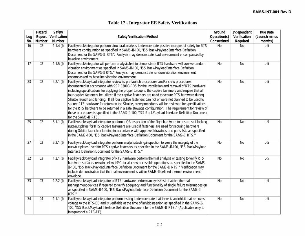
SAMS-INT-001 Rev D
C-2
Table 17 - Integrator EE Safety Verifications
Log No.
Hazard Report Number
Safety Verification
Number Safety Verification Method
Ground Operation(s) Constrained
Independent Verification Required
Due Date (Launch minus
months) 16 02 1.1.4 (I) Facility/rack/integrator perform structural analysis to demonstrate positive margins of safety for RTS
hardware configuration as specified in SAMS-II-100, "ISS Rack/Payload Interface Definition Document for the SAMS-II RTS". Analysis may demonstrate load environment encompassed by baseline environment.
No No L-5
17 02 1.1.5 (I) Facility/rack/integrator will perform analysis/test to demonstrate RTS hardware will survive random vibration environment as specified in SAMS-II-100, "ISS Rack/Payload Interface Definition Document for the SAMS-II RTS." Analysis may demonstrate random vibration environment encompassed by baseline vibration environment.
No No L-5
23 02 4.2.1 (I) Facility/rack/payload integrator review its pre-launch procedures and/or crew procedures documented in accordance with SSP 52000-PDS for the installation and removal of RTS hardware including specifications for applying the proper torque to the captive fasteners and require that all four captive fasteners be utilized if the captive fasteners are used to secure RTS hardware during Shuttle launch and landing. If all four captive fasteners can not or were not planned to be used to secure RTS hardware for return on the Shuttle, crew procedures will be reviewed for specifications for the RTS hardware to be returned in a safe stowage configuration. The requirement for review of these procedures is specified in the SAMS-II-100, "ISS Rack/Payload Interface Definition Document for the SAMS-II RTS."
No No L-5
25 02 5.1.1 (I) Facility/rack/payload integrator perform a QA inspection of the flight hardware to ensure self-locking nuts/nut plates for RTS captive fasteners are used if fasteners are used for securing hardware during Orbiter launch or landing in accordance with approved drawings and parts lists as specified in the SAMS-100, "ISS Rack/Payload Interface Definition Document for the SAMS-II RTS."
No No L-5
27 02 5.2.1 (I) Facility/rack/payload integrator perform analysis/testing/inspection to verify the integrity of the nuts/nut plates used for RTS captive fasteners as specified in the SAMS-II-100, "ISS Rack/Payload Interface Definition Document for the SAMS-II RTS."
No No L-5
32 03 1.2.1 (I) Facility/rack/payload integrator of RTS hardware perform thermal analysis or testing to verify RTS hardware surfaces remain below 49ºC for all crew accessible operations as specified in the SAMS-II-100, "ISS Rack/Payload Interface Definition Document for the SAMS-II RTS." Verification may include demonstration that thermal environment is within SAMS-II defined thermal environment envelope.
No No L-5
33 03 1.2.2 (I) Facility/rack/payload integrator of RTS hardware perform analysis/test of active thermal management devices if required to verify adequacy and functionality of single failure tolerant design as specified in SAMS-II-100, "ISS Rack/Payload Interface Definition Document for the SAMS-II RTS."
No No L-5
34 04 1.1.1 (I) Facility/rack/payload integrator perform testing to demonstrate that there is an inhibit that removes voltage to the RTS-EE and is verifiable at the time of inhibit insertion as specified in the SAMS-II-100, "ISS Rack/Payload Interface Definition Document for the SAMS-II RTS." (Applicable only to integrator of a RTS-EE).
No No L-5

SAMS-INT-001 Rev D
C-3
Log No.
Hazard Report Number
Safety Verification
Number Safety Verification Method
Ground Operation(s) Constrained
Independent Verification Required
Due Date (Launch minus
months) 35 04 1.1.2 (I) Facility/rack/payload integrator perform testing to verify that the maximum voltage supplied to the
RTS-EE is no greater than 32 volts as specified in the SAMS-II-100, "ISS Rack/Payload Interface Definition Document for the SAMS-II RTS." (Applicable only to an integrator of a RTS-EE).
No No L-5
40 04 1.4.2 (I) Facility/rack/payload integrator perform a ground based certification test utilizing RTS flight hardware (which may not be specific RTS flight hardware unit) or flight-like RTS hardware and the planned on-orbit installation operations to ensure there is a bond between the RTS hardware and the hardware of the facility/rack/payload integrator which meets the requirements of SSP 30245 as specified in the SAMS-II-100, "ISS Rack/Payload Interface Definition Document for the SAMS-II RTS".
No No L-5
41 04 2.1 (I) Facility/rack/payload integrator review the crew procedures documented in accordance with SSP 52000-PDS for RTS installation and removal operations including steps to insert a verifiable inhibit to remove power to the RTS-EE as specified in the SAMS-II-100, "ISS Rack/Payload Interface Definition Document for the SAMS-II RTS."
No No L-5
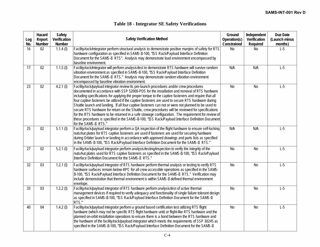
SAMS-INT-001 Rev D
C-4
Table 18 - Integrator SE Safety Verifications
Log No.
Hazard Report Number
Safety Verification
Number Safety Verification Method
Ground Operation(s) Constrained
Independent Verification Required
Due Date (Launch minus
months) 16 02 1.1.4 (I) Facility/rack/integrator perform structural analysis to demonstrate positive margins of safety for RTS
hardware configuration as specified in SAMS-II-100, "ISS Rack/Payload Interface Definition Document for the SAMS-II RTS". Analysis may demonstrate load environment encompassed by baseline environment.
No No L-5
17 02 1.1.5 (I) Facility/rack/integrator will perform analysis/test to demonstrate RTS hardware will survive random vibration environment as specified in SAMS-II-100, "ISS Rack/Payload Interface Definition Document for the SAMS-II RTS." Analysis may demonstrate random vibration environment encompassed by baseline vibration environment.
N/A N/A L-5
23 02 4.2.1 (I) Facility/rack/payload integrator review its pre-launch procedures and/or crew procedures documented in accordance with SSP 52000-PDS for the installation and removal of RTS hardware including specifications for applying the proper torque to the captive fasteners and require that all four captive fasteners be utilized if the captive fasteners are used to secure RTS hardware during Shuttle launch and landing. If all four captive fasteners can not or were not planned to be used to secure RTS hardware for return on the Shuttle, crew procedures will be reviewed for specifications for the RTS hardware to be returned in a safe stowage configuration. The requirement for review of these procedures is specified in the SAMS-II-100, "ISS Rack/Payload Interface Definition Document for the SAMS-II RTS."
No No L-5
25 02 5.1.1 (I) Facility/rack/payload integrator perform a QA inspection of the flight hardware to ensure self-locking nuts/nut plates for RTS captive fasteners are used if fasteners are used for securing hardware during Orbiter launch or landing in accordance with approved drawings and parts lists as specified in the SAMS-II-100, "ISS Rack/Payload Interface Definition Document for the SAMS-II RTS."
N/A N/A L-5
27 02 5.2.1 (I) Facility/rack/payload integrator perform analysis/testing/inspection to verify the integrity of the nuts/nut plates used for RTS captive fasteners as specified in the SAMS-II-100, "ISS Rack/Payload Interface Definition Document for the SAMS-II RTS."
No No L-5
32 03 1.2.1 (I) Facility/rack/payload integrator of RTS hardware perform thermal analysis or testing to verify RTS hardware surfaces remain below 49ºC for all crew accessible operations as specified in the SAMS-II-100, "ISS Rack/Payload Interface Definition Document for the SAMS-II RTS." Verification may include demonstration that thermal environment is within SAMS-II defined thermal environment envelope.
No No L-5
33 03 1.2.2 (I) Facility/rack/payload integrator of RTS hardware perform analysis/test of active thermal management devices if required to verify adequacy and functionality of single failure tolerant design as specified in SAMS-II-100, "ISS Rack/Payload Interface Definition Document for the SAMS-II RTS."
No No L-5
40 04 1.4.2 (I) Facility/rack/payload integrator perform a ground based certification test utilizing RTS flight hardware (which may not be specific RTS flight hardware unit) or flight-like RTS hardware and the planned on-orbit installation operations to ensure there is a bond between the RTS hardware and the hardware of the facility/rack/payload integrator which meets the requirements of SSP 30245 as specified in the SAMS-II-100, "ISS Rack/Payload Interface Definition Document for the SAMS-II
No No L-5
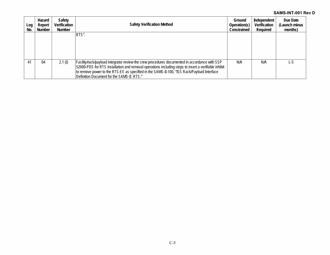
SAMS-INT-001 Rev D
C-5
Log No.
Hazard Report Number
Safety Verification
Number Safety Verification Method
Ground Operation(s) Constrained
Independent Verification Required
Due Date (Launch minus
months) RTS".
41 04 2.1 (I) Facility/rack/payload integrator review the crew procedures documented in accordance with SSP 52000-PDS for RTS installation and removal operations including steps to insert a verifiable inhibit to remove power to the RTS-EE as specified in the SAMS-II-100, "ISS Rack/Payload Interface Definition Document for the SAMS-II RTS."
N/A N/A L-5

SAMS-INT-001 Rev D
C-6
Table 19 - TSH-ES Safety Verifications passed to the Integrator
AIDD Section Log No. Hazard Report
Number Safety
Verification Number
Safety Verification Method Ground
Operation(s) Constrained
Independent Verification Required
Due Date (Launch minus
months) 3.3.5.1 15 STD 10(a).3 (O) Inspection. SAMS Project verifies that the requirement to verify the
thermal environment for TSH-ES application for the TSH-ES surfaces to remain below 49 deg C, is passed to the Integrator through AIDD SAMS-INT-001.
Yes No L-20
3.3.3.5 20 STD 11(b).6 (O) Inspection. SAMS Project verifies that the requirement to perform a bonding test (ground mounted THS-ES units only) to insure that the bonding interface conforms to SSP 30245 is passed to the Integrator through AIDD SAMS-INT-001.
Yes No L-20
3.3.2.4.3 23 STD 15(c) (O) Inspection. SAMS Project verifies that the requirement to verify that the TSH-ES hardware envelope and planned ISS flight operations do not impede emergency IVA egress to adjacent pressurized volumes is passed to the Integrator through AIDD SAMS-INT-001.
No No L-20
3.3.5.4 26 01 1.1.3 (O) Analysis. SAMS Project verifies that the requirement to have TSH-ES load environment within specification is passed to the Integrator through AIDD SAMS-INT-001.
No Yes L-20
3.3.2.4.2 33 01 4.3.1 (O) Inspection. SAMS Project verifies that the requirement to apply proper torque (20 +/- 1 in-lb + running torque) to all four captive fasteners and to have all four captive fasteners to be engaged is passed to the Integrator through AIDD SAMS-INT-001 to be included in the integrator pre-launch and/or on orbit installation/removal procedures.
No No L-20
5.1.6 34 01 4.3.2 (O) Inspection. SAMS Project verifies that the requirement to use only approved procedures with specifications for the TSH-ES hardware to be returned in a safe stowage configuration is passed to the Integrator through AIDD SAMS-INT-001.
No No L-20
3.3.2.4.2 35 01 5.1.1 (O) Inspection. SAMS Project verifies that the requirement to perform a QA inspection of the flight hardware to ensure self-locking nuts/nut plates for TSH-ES captive fasteners are used if TSH-ES unit is mounted for launch/landing is passed to the Integrator through AIDD SAMS-INT-001.
No No L-20
3.3.2.4.2 37 01 5.2.1 (O) Inspection. SAMS Project verifies that the requirement to verify the integrity of the nuts/nut plates used for TSH-ES captive fasteners if unit is mounted for launch and landing is passed to the Integrator through AIDD SAMS-INT-001.
No No L-20

SAMS-INT-001 Rev D
D-1
APPENDIX D – PROCEDURE HISTORY / LOG SHEET

SAMS-INT-001 Rev D
D-2
PROCEDURE HISTORY/LOG SHEET NASA-GRC MICROGRAVITY SCIENCE DIVISION – ZIN TECHNOLOGIES
PART/ASSY NAME:
PART NUMBER: SERIAL NUMBER: PAGE:
ENTRY NO.
DESCRIPTION OF ACTION INITIALS DATE
Continued on Page:

SAMS-INT-001 Rev D
E-1
APPENDIX E – SAMS MEASUREMENT CAPABILITIES GRAPHS
SAMS requires accuracy of all measurements to be within 10% or 1.8µg (whichever is greater) for all measured values in the frequency range from 0.01Hz to 400Hz. SAMS verifies that the accuracy between DC and 400Hz is within 10% of the actual measurement. SAMS has not tried to experimentally remove the DC error from these results. SAMS has analytically calculated that accuracy between 0.01Hz to 400Hz should not exceed 4.5%. The graphs below show the relationship between several variables (temperature, aging, and misalignment) and absolute error.
-20-10
010
2030
-0.02-0.01
0
0.010.02
0
0.5
1
1.5
2
2.5
ΔT [°C]
Absolute Error - Thermal
Acceleration [g]
Erro
r [μg
]
00.5
11.5
2
-0.02-0.01
0
0.010.02-100
-50
0
50
100
time [years]
Absolute Error - Aging
Acceleration [g]
Erro
r [μg
]

SAMS-INT-001 Rev D
E-2
0
1
2
3
x 10-3
-0.02-0.01
0
0.010.02-0.1
-0.05
0
0.05
0.1
Misalignment [μrads]
Absolute Error - Misalignment
Acceleration [g]
Erro
r [μg
]
Resolution is measured directly and calculated analytically for each SAMS’ unit. The SAMS system has a worst case effective resolution of 0.8µg. However resolution is affected by the noise floor for small disturber forces. The noise floor graph below shows the analytical noise floor calculated for SAMS and the noise floor recorded in a vibration isolated test cell. The true noise floor would lie somewhere between.
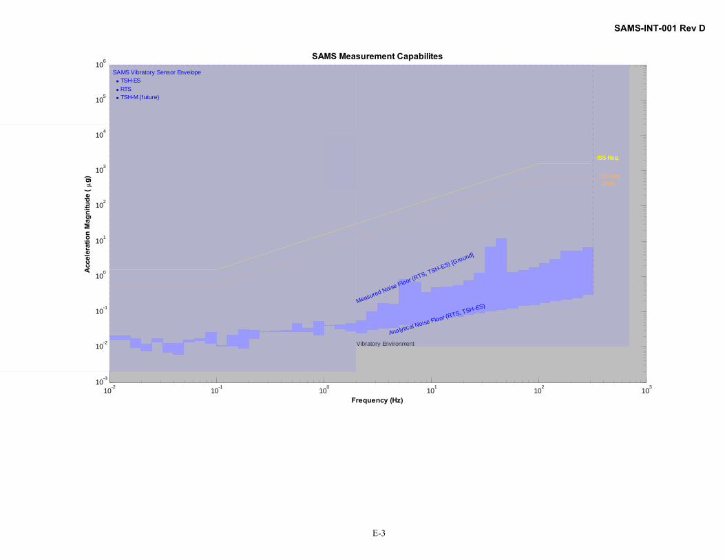
SAMS-INT-001 Rev D
E-3
10-2 10-1 100 101 102 10310-3
10-2
10-1
100
101
102
103
104
105
106
Vibratory Environment
SAMS Measurement Capabilites
Frequency (Hz)
Acce
lera
tion
Mag
nitu
de (
μg)
SAMS Vibratory Sensor Envelope • TSH-ES • RTS • TSH-M (future)
Measured Noise Floor (RTS, TSH-ES) [Ground]
Analytical Noise Floor (RTS, TSH-ES)
ISS Req.ISS Req.
ISS Req.-10dB