sp2 class i div. 2 handset/speaker amplifier station · pub. 42004-780l2c gai-tronics® corporation...
TRANSCRIPT
Pub. 42004-780L2C
G A I - T R O N I C S®
C O R P O R A T I O N A H U B B E L L C O M P A N Y
SP2 Class I DIV. 2
Handset/Speaker Amplifier Station
T A B L E O F C O N T E N T S
GAI-Tronics Corporation 400 E. Wyomissing Ave. Mohnton, PA 19540 USA 610-777-1374 800-492-1212 Fax: 610-796-5954
VISIT WWW.GAI-TRONICS.COM FOR PRODUCT LITERATURE AND MANUALS
Confidentiality Notice .....................................................................................................................1
General Information .......................................................................................................................1
Product Overview ................................................................................................................................... 1
Features .................................................................................................................................................... 2
Options ..................................................................................................................................................... 2
Installation ......................................................................................................................................3
Important Safety Instructions................................................................................................................ 3
Mounting the Enclosure ......................................................................................................................... 4
Opening the Station ................................................................................................................................ 4
Field Wiring and Configuration ............................................................................................................ 5 Termination PCBA ............................................................................................................................................... 6
Power ................................................................................................................................................................ 6 Direct Speaker Connection and Jumper Settings .............................................................................................. 7 RTU Inputs ....................................................................................................................................................... 8 RTU Output ...................................................................................................................................................... 9
Main PCBA......................................................................................................................................................... 10 Ethernet Connection ....................................................................................................................................... 10
Settings and Adjustments ..............................................................................................................11
Opening the Station .............................................................................................................................. 11
Main PCBA Configuration .................................................................................................................. 12 Write Protect (EEPROM) Jumper ....................................................................................................................... 12 WDOG Enable (Watchdog) Jumper ................................................................................................................... 12 Boot Enable Jumper ............................................................................................................................................ 12 Reset Switch ....................................................................................................................................................... 12 Speaker Volume .................................................................................................................................................. 12 Receiver Volume ................................................................................................................................................ 13 Station ID and Zone Selector .............................................................................................................................. 13
Main PCBA Indicators ......................................................................................................................... 13 Power LED ......................................................................................................................................................... 13 Heartbeat LED .................................................................................................................................................... 13 Ethernet Connection LEDs ................................................................................................................................. 14 Five Generic LEDs ............................................................................................................................................. 14
Attaching the Front Cover ................................................................................................................... 14
Programming ................................................................................................................................14
Table of contents Pub. 42004-780L2C
GAI-Tronics Corporation 400 E. Wyomissing Ave. Mohnton, PA 19540 USA 610-777-1374 800-492-1212 Fax: 610-796-5954
VISIT WWW.GAI-TRONICS.COM FOR PRODUCT LITERATURE AND MANUALS
Operation .......................................................................................................................................14
Page and Party Line Operation with Standard Handset .................................................................. 14
Options ...........................................................................................................................................15
70 V and 100 V Speaker Connections and Monitoring ..................................................................... 15
Headset Operation ................................................................................................................................ 15
All-Call ................................................................................................................................................... 16
Alternate Page Destination ................................................................................................................... 17
Troubleshooting ............................................................................................................................18
Specifications ................................................................................................................................19
Service and Spare Parts ................................................................................................................21
Reference .......................................................................................................................................21
Pub. 42004-780L2C
GAI-Tronics Corporation 400 E. Wyomissing Ave. Mohnton, PA 19540 USA 610-777-1374 800-492-1212 Fax: 610-796-5954
VISIT WWW.GAI-TRONICS.COM FOR PRODUCT LITERATURE AND MANUALS
G A I - T R O N I C S ® C O R P O R A T I O N A H U B B E L L C O M P A N Y
SP2 Class I Div. 2 Handset/Speaker Amplifier Station
Confidentiality Notice This manual is provided solely as an installation, operation, and maintenance guide, which contains sensitive business and technical information, that is confidential and proprietary to GAI-Tronics. GAI-Tronics retains all intellectual property and other rights in or to the information contained herein, and such information may only be used in connection with the operation of your GAI-Tronics product or system. This manual may not be disclosed in any form, in whole or in part, directly or indirectly, to any third party.
This product contains copyrighted computer programs stored in semiconductor memory. These programs are copyrighted by GAI-Tronics Corporation and may not be reproduced in any form without express written permission from GAI-Tronics.
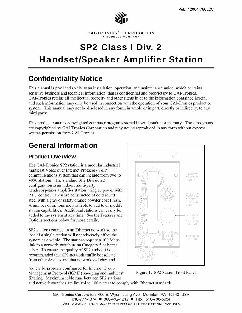
General Information Product Overview The GAI-Tronics SP2 station is a modular industrial multicast Voice over Internet Protocol (VoIP) communications system that can include from two to 4096 stations. The standard SP2 Division 2 configuration is an indoor, multi-party, handset/speaker amplifier station using ac power with RTU control. They are constructed of cold rolled steel with a gray or safety orange powder coat finish. A number of options are available to add to or modify station capabilities. Additional stations can easily be added to the system at any time. See the Features and Options sections below for more details.
SP2 stations connect to an Ethernet network so the loss of a single station will not adversely affect the system as a whole. The stations require a 100 Mbps link to a network switch using Category 5 or better cable. To ensure the quality of SP2 audio, it is recommended that SP2 network traffic be isolated from other devices and that network switches and
routers be properly configured for Internet Group Management Protocol (IGMP) snooping and multicast filtering. Maximum cable runs between SP2 stations and network switches are limited to 100 meters to comply with Ethernet standards.
Figure 1. SP2 Station Front Panel
Pub. 42004-780L2C SP2 Class I Div. 2 Handset/Speaker Amplifier Station Page 2 of 21
P:\Standard IOMs - Current Release\42004 Instr. Manuals\42004-780L2C.docx 02/17
Features
Flexible and highly configurable SMART technology featuring Ambient Level Sensing (ALS), real
time self-diagnostics of audio path connectivity with health check output via SMTP, and available
remote monitoring.
Real-time operation providing instantaneous page and party line communication without the delays
associated with conventional networked communications requiring a SIP server or conference bridge.
One-way live paging and alarm annunciation over system speakers without the delays associated with
record/playback paging systems.
Distributed amplifier topology so that the loss of a single amplifier shall not adversely affect the
system as a whole.
High efficiency (>80%) Class D paging amplifier provides up to 30 watts of speaker output at 8
ohms.
Five configurable multicast channels for full-duplex conference communication with party line
selector switch.
Eight configurable multicast channels for receiving page announcements.
One isolated output for beacon activation.
Two isolated inputs.
Configurable priority scheme to allow urgent/emergency pages to override less important pages.
Configuration stored in non-volatile memory eliminating the need to reprogram after power failures.
Field adjustable volume control for handset earpiece, headset earpiece, and speaker amplifier.
Configurable local speaker and nearby speaker mutual muting to prevent acoustic feedback of live
pages.
Off-hook and page switch timeout functionality.
Configurable virtual zoning ability.
Mutual provisioning mode allows easy system deployment.
USB interface for field or bench configuration.
Universal ac power supply.
Durable, high visibility safety orange powder coat finish.
Options
Optional 70/100V constant voltage termination board with 24-watt monitored output.
Available speaker amplifier only (no handset) model.
Optional headset with page pressbar for loud environments.
Five configurable multicast channels for alternate page destinations with page line selector.
All Call push button for secondary page destination.
PVC or Hytrel® handset cords in 6-, 15-, or 25-foot lengths.
Conformal coating for PCBA.
Configurable pre-announcement tone.
Pub. 42004-780L2C SP2 Class I Div. 2 Handset/Speaker Amplifier Station Page 3 of 21
P:\Standard IOMs - Current Release\42004 Instr. Manuals\42004-780L2C.docx 02/17
Installation
Important Safety Instructions
Read, follow, and retain instructions—All safety and operating instructions should be read and
followed before operating the unit. Retain instructions for future reference.
Heed warnings—Adhere to all warnings on the unit and in the operating instructions.
Attachments—Attachments not recommended by the product manufacturer should not be used, as
they may cause hazards.
Servicing—Do not attempt to service this unit by yourself. Opening or removing covers may expose
you to dangerous voltage or other hazards. Refer all servicing to qualified service personnel.
ATTENTIONInstall equipment without modification and according to all applicable local,
national and international electrical codes. North America - Consult the National Electrical Code (NFPA
70), Canadian Standards Association (CSA 22.1), and local codes for specific requirements regarding
your installation. Class 2 circuit wiring must be performed in accordance with NEC 725.55.
This equipment is suitable for use in Class I Division 2 Groups A, B, C and D, Class II Division 2 Groups
F and G, Class III, OR non-hazardous locations only. Combinations of equipment in your system are
subject to investigation by the local authority having jurisdiction at the time of installation.
WARNING Do not install this equipment in hazardous areas other than those indicated
on the approval listing in the “Specifications” section of this manual. Such installation may cause a
safety hazard and consequent injury or property damage.
WARNING —EXPLOSION HAZARD—Do not disconnect equipment unless power has
been removed or the area is known to be non-hazardous. Averttissement—Risque d’explosion—avant de
déconnector l’equipment, couper le courant ou s’assurer que l’emplacement est désigné non dangereux.
These enclosures must be installed by trained, qualified and competent personnel. Installation must
comply with state and national regulations, as well as safety practices for this type of equipment.
The mounting location must be flat and provide proper clearance, rigidity and strength to support the
enclosure and all contained devices.
WARNING Do not disconnect equipment while energized.
Ensure proper grounding to protective earthing.
Pub. 42004-780L2C SP2 Class I Div. 2 Handset/Speaker Amplifier Station Page 4 of 21
P:\Standard IOMs - Current Release\42004 Instr. Manuals\42004-780L2C.docx 02/17
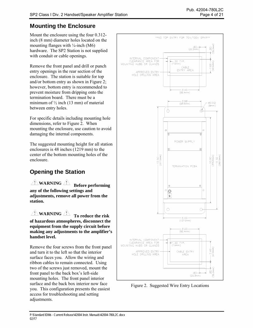
Mounting the Enclosure Mount the enclosure using the four 0.312-inch (8 mm) diameter holes located on the mounting flanges with ¼-inch (M6) hardware. The SP2 Station is not supplied with conduit or cable openings.
Remove the front panel and drill or punch entry openings in the rear section of the enclosure. The station is suitable for top and/or bottom entry as shown in Figure 2; however, bottom entry is recommended to prevent moisture from dripping onto the termination board. There must be a minimum of ½ inch (13 mm) of material between entry holes.
For specific details including mounting hole dimensions, refer to Figure 2. When mounting the enclosure, use caution to avoid damaging the internal components.
The suggested mounting height for all station enclosures is 48 inches (1219 mm) to the center of the bottom mounting holes of the enclosure.
Opening the Station
WARNING Before performing any of the following settings and adjustments, remove all power from the station.
WARNING To reduce the risk of hazardous atmospheres, disconnect the equipment from the supply circuit before making any adjustments to the amplifier’s handset level.
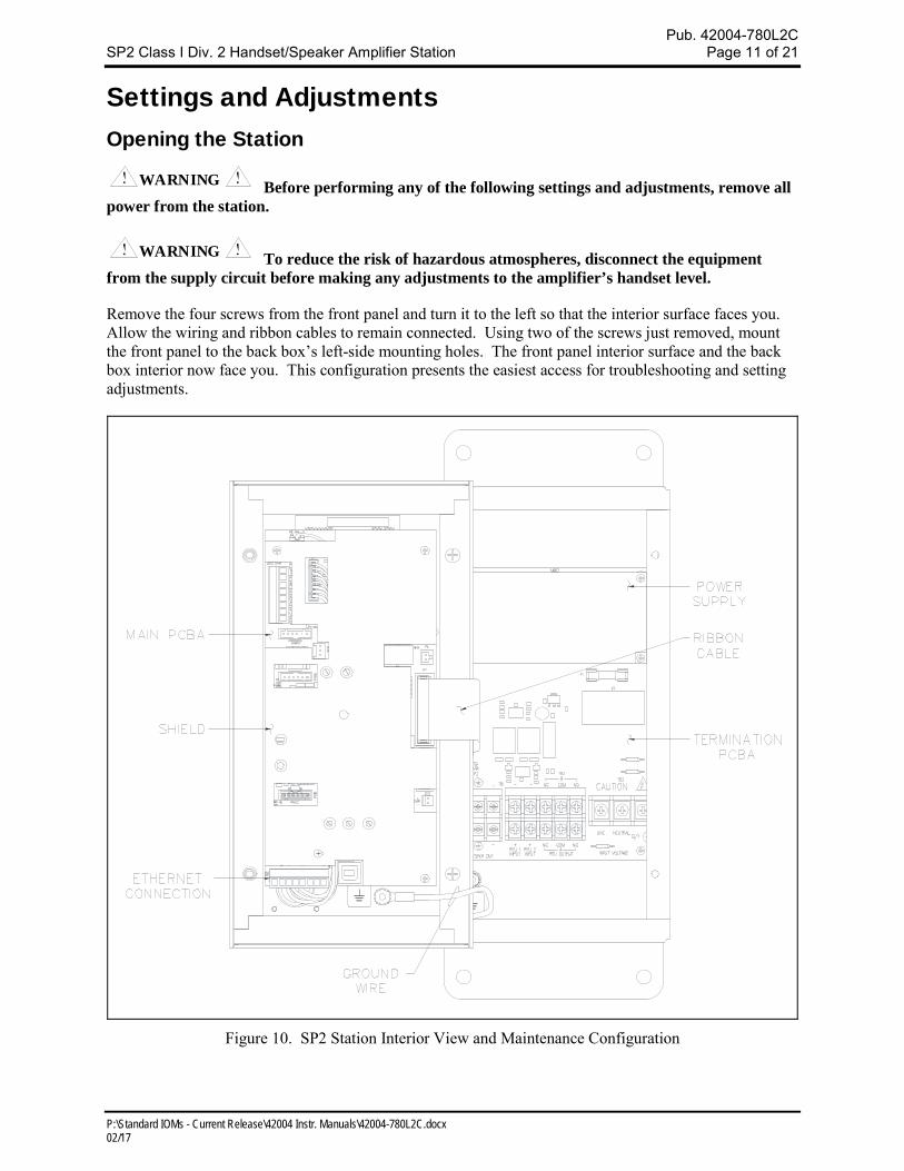
Remove the four screws from the front panel and turn it to the left so that the interior surface faces you. Allow the wiring and ribbon cables to remain connected. Using two of the screws just removed, mount the front panel to the back box’s left-side mounting holes. The front panel interior surface and the back box interior now face you. This configuration presents the easiest access for troubleshooting and setting adjustments.
Figure 2. Suggested Wire Entry Locations
Pub. 42004-780L2C SP2 Class I Div. 2 Handset/Speaker Amplifier Station Page 5 of 21
P:\Standard IOMs - Current Release\42004 Instr. Manuals\42004-780L2C.docx 02/17
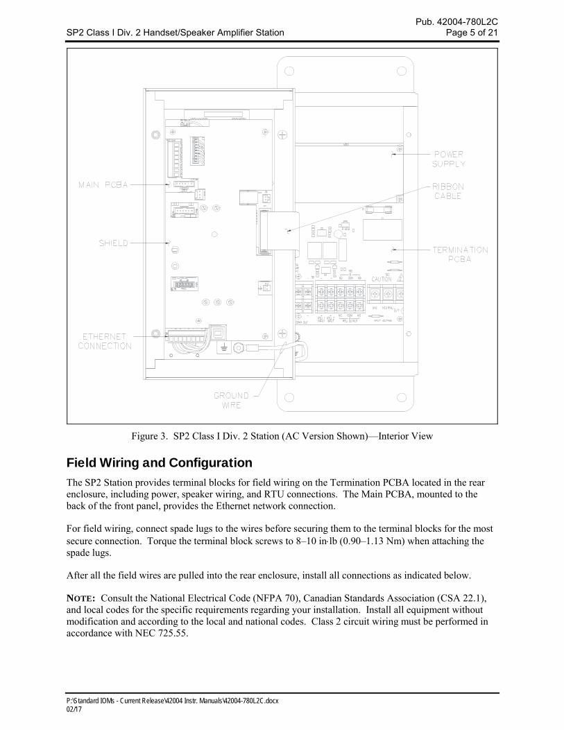
Figure 3. SP2 Class I Div. 2 Station (AC Version Shown)—Interior View
Field Wiring and Configuration The SP2 Station provides terminal blocks for field wiring on the Termination PCBA located in the rear enclosure, including power, speaker wiring, and RTU connections. The Main PCBA, mounted to the back of the front panel, provides the Ethernet network connection.
For field wiring, connect spade lugs to the wires before securing them to the terminal blocks for the most secure connection. Torque the terminal block screws to 8–10 inlb (0.90–1.13 Nm) when attaching the spade lugs.
After all the field wires are pulled into the rear enclosure, install all connections as indicated below.
NOTE: Consult the National Electrical Code (NFPA 70), Canadian Standards Association (CSA 22.1), and local codes for the specific requirements regarding your installation. Install all equipment without modification and according to the local and national codes. Class 2 circuit wiring must be performed in accordance with NEC 725.55.
Pub. 42004-780L2C SP2 Class I Div. 2 Handset/Speaker Amplifier Station Page 6 of 21
P:\Standard IOMs - Current Release\42004 Instr. Manuals\42004-780L2C.docx 02/17
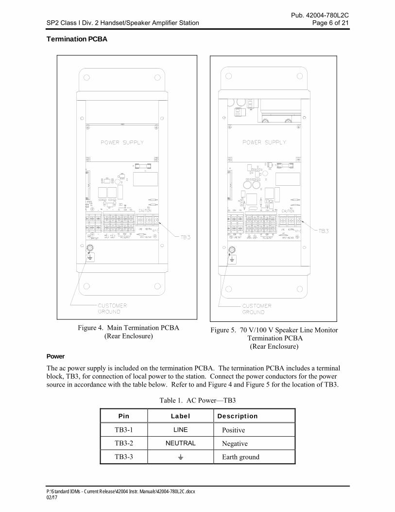
Termination PCBA
Power
The ac power supply is included on the termination PCBA. The termination PCBA includes a terminal block, TB3, for connection of local power to the station. Connect the power conductors for the power source in accordance with the table below. Refer to and Figure 4 and Figure 5 for the location of TB3.
Table 1. AC Power—TB3
Pin Label Description
TB3-1 LINE Positive
TB3-2 NEUTRAL Negative
TB3-3 ⏚ Earth ground
Figure 5. 70 V/100 V Speaker Line Monitor Termination PCBA
(Rear Enclosure)
Figure 4. Main Termination PCBA (Rear Enclosure)
Pub. 42004-780L2C SP2 Class I Div. 2 Handset/Speaker Amplifier Station Page 7 of 21
P:\Standard IOMs - Current Release\42004 Instr. Manuals\42004-780L2C.docx 02/17
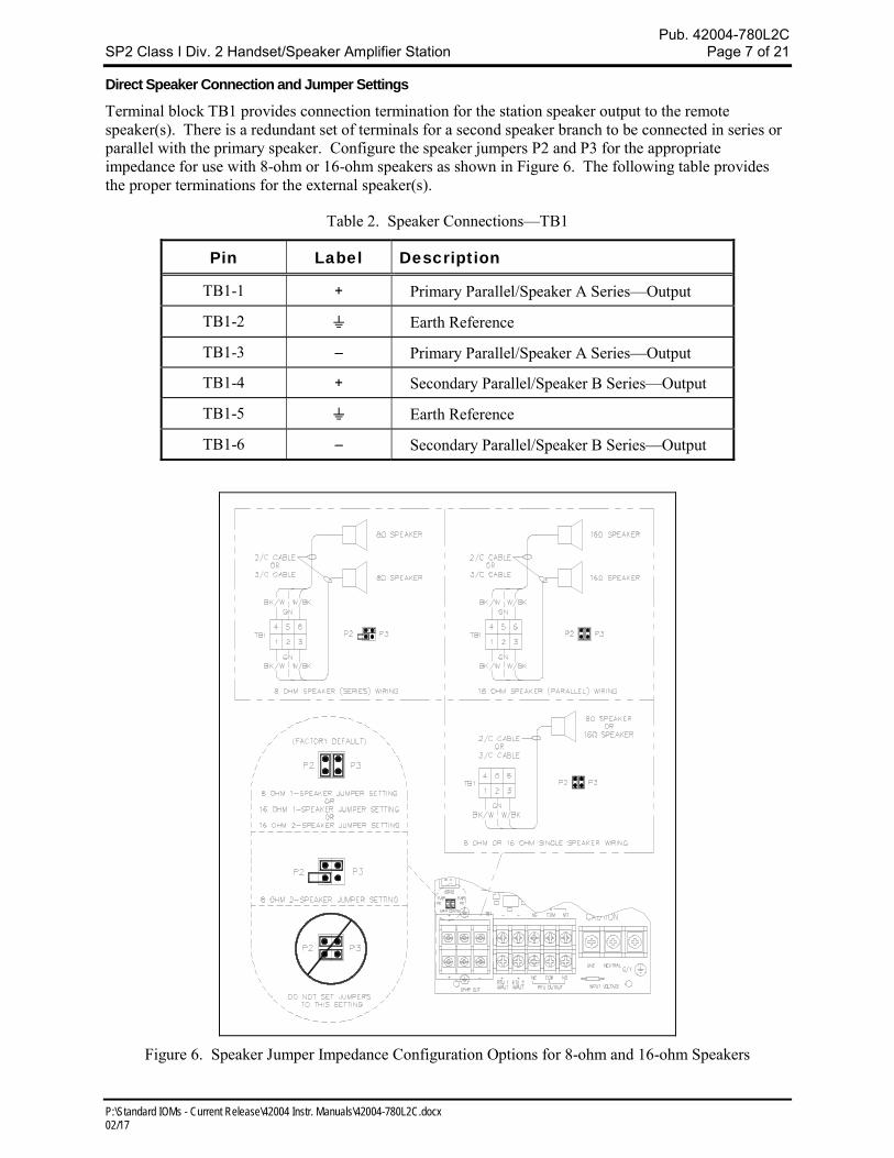
Direct Speaker Connection and Jumper Settings
Terminal block TB1 provides connection termination for the station speaker output to the remote speaker(s). There is a redundant set of terminals for a second speaker branch to be connected in series or parallel with the primary speaker. Configure the speaker jumpers P2 and P3 for the appropriate impedance for use with 8-ohm or 16-ohm speakers as shown in Figure 6. The following table provides the proper terminations for the external speaker(s).
Table 2. Speaker Connections—TB1
Pin Label Description
TB1-1 + Primary Parallel/Speaker A Series—Output
TB1-2 ⏚ Earth Reference
TB1-3 – Primary Parallel/Speaker A Series—Output
TB1-4 + Secondary Parallel/Speaker B Series—Output
TB1-5 ⏚ Earth Reference
TB1-6 – Secondary Parallel/Speaker B Series—Output
Figure 6. Speaker Jumper Impedance Configuration Options for 8-ohm and 16-ohm Speakers
Pub. 42004-780L2C SP2 Class I Div. 2 Handset/Speaker Amplifier Station Page 8 of 21
P:\Standard IOMs - Current Release\42004 Instr. Manuals\42004-780L2C.docx 02/17
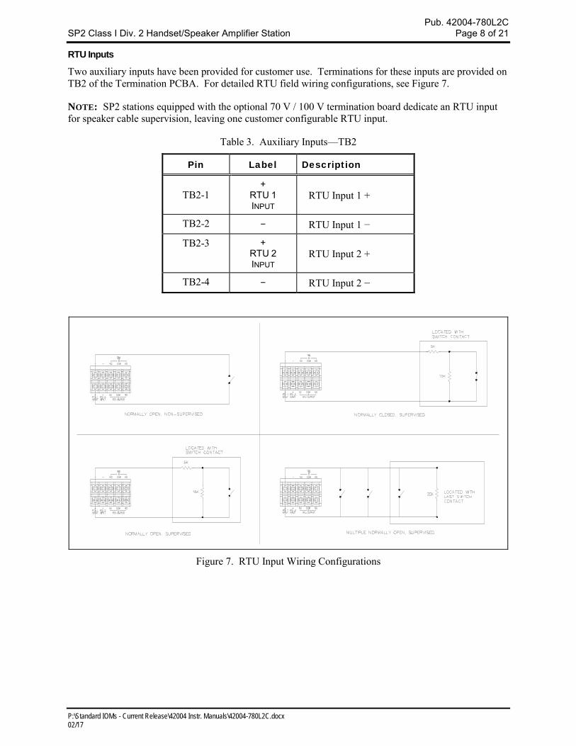
RTU Inputs
Two auxiliary inputs have been provided for customer use. Terminations for these inputs are provided on TB2 of the Termination PCBA. For detailed RTU field wiring configurations, see Figure 7.
NOTE: SP2 stations equipped with the optional 70 V / 100 V termination board dedicate an RTU input for speaker cable supervision, leaving one customer configurable RTU input.
Table 3. Auxiliary Inputs—TB2
Pin Label Description
TB2-1 +
RTU 1 INPUT
RTU Input 1 +
TB2-2 − RTU Input 1 −
TB2-3 + RTU 2 INPUT
RTU Input 2 +
TB2-4 − RTU Input 2 −
Figure 7. RTU Input Wiring Configurations
Pub. 42004-780L2C SP2 Class I Div. 2 Handset/Speaker Amplifier Station Page 9 of 21
P:\Standard IOMs - Current Release\42004 Instr. Manuals\42004-780L2C.docx 02/17
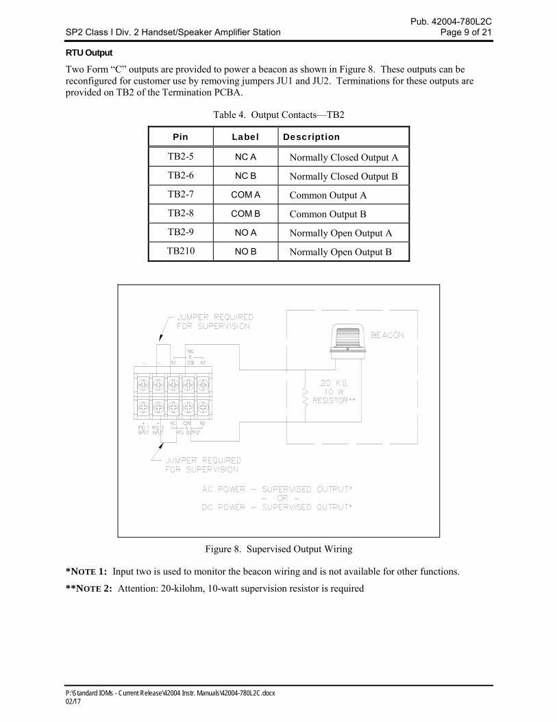
RTU Output
Two Form “C” outputs are provided to power a beacon as shown in Figure 8. These outputs can be reconfigured for customer use by removing jumpers JU1 and JU2. Terminations for these outputs are provided on TB2 of the Termination PCBA.
Table 4. Output Contacts—TB2
Pin Label Description
TB2-5 NC A Normally Closed Output A
TB2-6 NC B Normally Closed Output B
TB2-7 COM A Common Output A
TB2-8 COM B Common Output B
TB2-9 NO A Normally Open Output A
TB210 NO B Normally Open Output B
Figure 8. Supervised Output Wiring
*NOTE 1: Input two is used to monitor the beacon wiring and is not available for other functions.
**NOTE 2: Attention: 20-kilohm, 10-watt supervision resistor is required
Pub. 42004-780L2C SP2 Class I Div. 2 Handset/Speaker Amplifier Station Page 10 of 21
P:\Standard IOMs - Current Release\42004 Instr. Manuals\42004-780L2C.docx 02/17
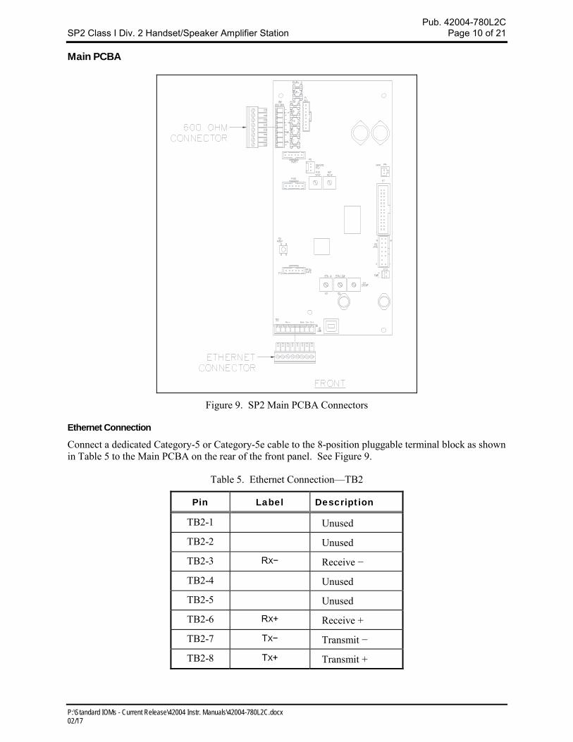
Main PCBA
Figure 9. SP2 Main PCBA Connectors
Ethernet Connection
Connect a dedicated Category-5 or Category-5e cable to the 8-position pluggable terminal block as shown in Table 5 to the Main PCBA on the rear of the front panel. See Figure 9.
Table 5. Ethernet Connection—TB2
Pin Label Description
TB2-1 Unused
TB2-2 Unused
TB2-3 RX− Receive −
TB2-4 Unused
TB2-5 Unused
TB2-6 RX+ Receive +
TB2-7 TX− Transmit −
TB2-8 TX+ Transmit +
Pub. 42004-780L2C SP2 Class I Div. 2 Handset/Speaker Amplifier Station Page 11 of 21
P:\Standard IOMs - Current Release\42004 Instr. Manuals\42004-780L2C.docx 02/17
Settings and Adjustments Opening the Station
WARNING Before performing any of the following settings and adjustments, remove all power from the station.
WARNING To reduce the risk of hazardous atmospheres, disconnect the equipment from the supply circuit before making any adjustments to the amplifier’s handset level.
Remove the four screws from the front panel and turn it to the left so that the interior surface faces you. Allow the wiring and ribbon cables to remain connected. Using two of the screws just removed, mount the front panel to the back box’s left-side mounting holes. The front panel interior surface and the back box interior now face you. This configuration presents the easiest access for troubleshooting and setting adjustments.
Figure 10. SP2 Station Interior View and Maintenance Configuration
Pub. 42004-780L2C SP2 Class I Div. 2 Handset/Speaker Amplifier Station Page 12 of 21
P:\Standard IOMs - Current Release\42004 Instr. Manuals\42004-780L2C.docx 02/17
Main PCBA Configuration
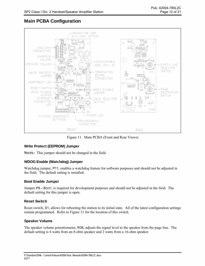
Figure 11. Main PCBA (Front and Rear Views)
Write Protect (EEPROM) Jumper
NOTE: This jumper should not be changed in the field.
WDOG Enable (Watchdog) Jumper
Watchdog jumper, P11, enables a watchdog feature for software purposes and should not be adjusted in the field. The default setting is installed.
Boot Enable Jumper
Jumper P8 – BOOT, is required for development purposes and should not be adjusted in the field. The default setting for this jumper is open.
Reset Switch
Reset switch, S1, allows for rebooting the station to its initial state. All of the latest configuration settings remain programmed. Refer to Figure 11 for the location of this switch.
Speaker Volume
The speaker volume potentiometer, R36, adjusts the signal level to the speaker from the page line. The default setting is 4 watts from an 8-ohm speaker and 2 watts from a 16-ohm speaker.
Pub. 42004-780L2C SP2 Class I Div. 2 Handset/Speaker Amplifier Station Page 13 of 21
P:\Standard IOMs - Current Release\42004 Instr. Manuals\42004-780L2C.docx 02/17
WARNING Maximum output power may exceed rated speaker wattage resulting in speaker
damage.
This setting can also be configured via USB or Ethernet connection using the command line interface.
Receiver Volume
Receiver volume potentiometer, R37, adjusts the audio signal level supplied to the handset and headset
earpieces. The unit stores the audio level settings individually for the handset and headset earpieces. In
the case where the handset is used, the volume for both the handset and headset are defined by the setting
for the handset. In the case where the headset is used, the volume for both the headset and handset are
defined by the setting for the headset.
To adjust the volume for the handset, remove the handset from the cradle, turn the RCVR potentiometer
R37 fully counter clockwise then adjust the potentiometer while listening in the earpiece for the
appropriate test tone level required.
To adjust the volume for the headset, install the headset, turn the RCVR potentiometer R37 fully counter
clockwise then adjust the potentiometer while listening in the earpiece for the appropriate test tone level
required.
These settings can also be configured via USB or Ethernet connection using the command line interface.
Station ID and Zone Selector
Two station number and one group number selector switches are used for mutual provisioning of the
station. To use this mode, a master station set up is required to retrieve the mutual provisioning
configuration.
This mode is intended to allow all SP2 Stations within a system solution to mutually maintain their
configurations in runtime, without the support of a fixed central point such as a server, and without the
need for human administration.
This mode is also intended to streamline the initial set-up process by separating the system
design/planning and system installation stages of a customer solution, and also intended to minimize the
cost and effort required to maintain/replace faulty SPP stations in an existing system.
In mutual provisioning mode, SPP stations shall operate using the system configuration obtained from
other SPP stations already on the network using the command channel.
Main PCBA Indicators
Power LED
The Power LED located on the Main PCBA illuminates when power is applied to the station indicating
the main board power supply is operational. Refer to Figure 11 on Page 12 for the location of the power
LED.
Heartbeat LED
The Heartbeat LED located on the Main PCBA will flash once communication over the LAN is
established to indicate the microprocessor is operational. Refer to Figure 11 on Page 12 for the location
of this LED.
Pub. 42004-780L2C SP2 Class I Div. 2 Handset/Speaker Amplifier Station Page 14 of 21
P:\Standard IOMs - Current Release\42004 Instr. Manuals\42004-780L2C.docx 02/17
Ethernet Connection LEDs
Three Ethernet Connection LEDs are located on the Main PCBA; Link (LNK), Link Speed (SPD), and
Activity (ACT). The LNK LED is blue, the SPD LED is green, and the ACT LED is yellow. The LNK and
SPD LEDs must be off to indicate that a 100 Mb Ethernet link is active. The activity LED; ACT, will blink
yellow to indicate Ethernet data activity. Refer to Figure 11 on Page 12 for the location.
Five Generic LEDs
Five LEDs are located on the Main PCBA and are configured through firmware. Refer to Figure 11 on
Page 12 for location of these LEDs. Additional information for configuring these LED indicators is
provided in the SP2 station configuration manual. Please see the reference section for a listing of
applicable publications.
Attaching the Front Cover
After all adjustments have been completed, place the front cover on the rear enclosure, being careful not
to pinch any cables. Secure the front cover using the four screws and washers provided. Torque the
screws to 10–12 inlb (1.13–1.36 Nm).
Programming
SP2 stations are factory configured to provide basic Page/Party® functions upon power-up. For custom
configurations and larger system designs the stations may need to be reconfigured. Refer to Publication
42004-784A for detailed configuration instructions for setting SP2 configuration parameters. A list of
reference documents is located in the reference section of this document.
Operation
Page and Party Line Operation with Standard Handset
Complete the following steps to make a page announcement from an SP2 handset station:
1. Lift the handset from the cradle.
2. Rotate the ALT PAGE selector switch (if available) to the desired multicast channel, or press the ALL
CALL button (if available) to select the desired optional destination for the page announcement.
3. If party line conversation is desired, rotate the selector switch to an unoccupied party line.
4. Press and hold the PUSH TO PAGE button (not necessary when using the optional ALL CALL button).
5. After the short “wait” tone is heard (if configured), speak directly into the microphone to broadcast
your page announcement.
6. Release the PUSH TO PAGE or handset pressbar and wait for a response on the party line (if requested).
The paged individual(s) respond by picking up a station handset and turning the selector switch to the
requested party line. Party line communication is not broadcast over the system speakers. Other
individual(s) can also pick up a handset and join the conversation at any time. Always return the handset
to the cradle following a page or a party line conversation.
NOTE: The SP2 Station incorporates a noise-canceling microphone to reduce transmitted ambient noise.
This requires the user to place the microphone as close as possible to their mouth.
Pub. 42004-780L2C SP2 Class I Div. 2 Handset/Speaker Amplifier Station Page 15 of 21
P:\Standard IOMs - Current Release\42004 Instr. Manuals\42004-780L2C.docx 02/17
Options All SP2 Station options are factory installed.
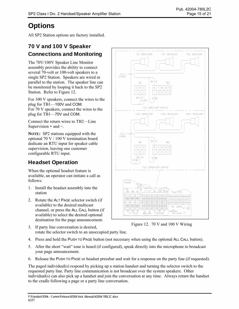
70 V and 100 V Speaker Connections and Monitoring The 70V/100V Speaker Line Monitor assembly provides the ability to connect several 70-volt or 100-volt speakers to a single SP2 Station. Speakers are wired in parallel to the station. The speaker line can be monitored by looping it back to the SP2 Station. Refer to Figure 12.
For 100 V speakers, connect the wires to the plug for TB1—100V and COM. For 70 V speakers, connect the wires to the plug for TB1—70V and COM.
Connect the return wires to TB2—Line Supervision + and −.
NOTE: SP2 stations equipped with the optional 70 V / 100 V termination board dedicate an RTU input for speaker cable supervision, leaving one customer configurable RTU input.
Headset Operation When the optional headset feature is available, an operator can initiate a call as follows:
1. Install the headset assembly into the station
2. Rotate the ALT PAGE selector switch (if available) to the desired multicast channel, or press the ALL CALL button (if available) to select the desired optional destination for the page announcement.
3. If party line conversation is desired, rotate the selector switch to an unoccupied party line.
4. Press and hold the PUSH TO PAGE button (not necessary when using the optional ALL CALL button).
5. After the short “wait” tone is heard (if configured), speak directly into the microphone to broadcast your page announcement.
6. Release the PUSH TO PAGE or headset pressbar and wait for a response on the party line (if requested).
The paged individual(s) respond by picking up a station handset and turning the selector switch to the requested party line. Party line communication is not broadcast over the system speakers. Other individual(s) can also pick up a handset and join the conversation at any time. Always return the handset to the cradle following a page or a party line conversation.
Figure 12. 70 V and 100 V Wiring
Pub. 42004-780L2C SP2 Class I Div. 2 Handset/Speaker Amplifier Station Page 16 of 21
P:\Standard IOMs - Current Release\42004 Instr. Manuals\42004-780L2C.docx 02/17
NOTE: For stations with an auxiliary jack, the Model 10401-201 Headset and 10416-103 Extension Cord allows the user to be hands-free and mobile while maintaining communication. When connected, the handset microphone is disabled.
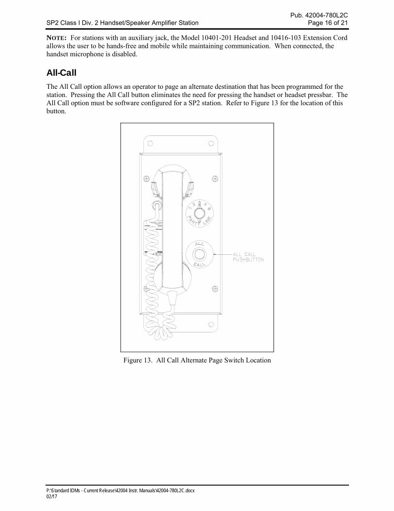
All-Call The All Call option allows an operator to page an alternate destination that has been programmed for the station. Pressing the All Call button eliminates the need for pressing the handset or headset pressbar. The All Call option must be software configured for a SP2 station. Refer to Figure 13 for the location of this button.
Figure 13. All Call Alternate Page Switch Location
Pub. 42004-780L2C SP2 Class I Div. 2 Handset/Speaker Amplifier Station Page 17 of 21
P:\Standard IOMs - Current Release\42004 Instr. Manuals\42004-780L2C.docx 02/17
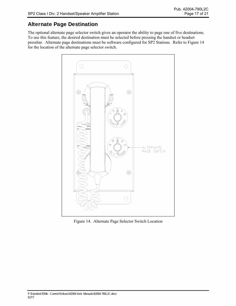
Alternate Page Destination The optional alternate page selector switch gives an operator the ability to page one of five destinations. To use this feature, the desired destination must be selected before pressing the handset or headset pressbar. Alternate page destinations must be software configured for SP2 Stations. Refer to Figure 14 for the location of the alternate page selector switch.
Figure 14. Alternate Page Selector Switch Location
Pub. 42004-780L2C SP2 Class I Div. 2 Handset/Speaker Amplifier Station Page 18 of 21
P:\Standard IOMs - Current Release\42004 Instr. Manuals\42004-780L2C.docx 02/17
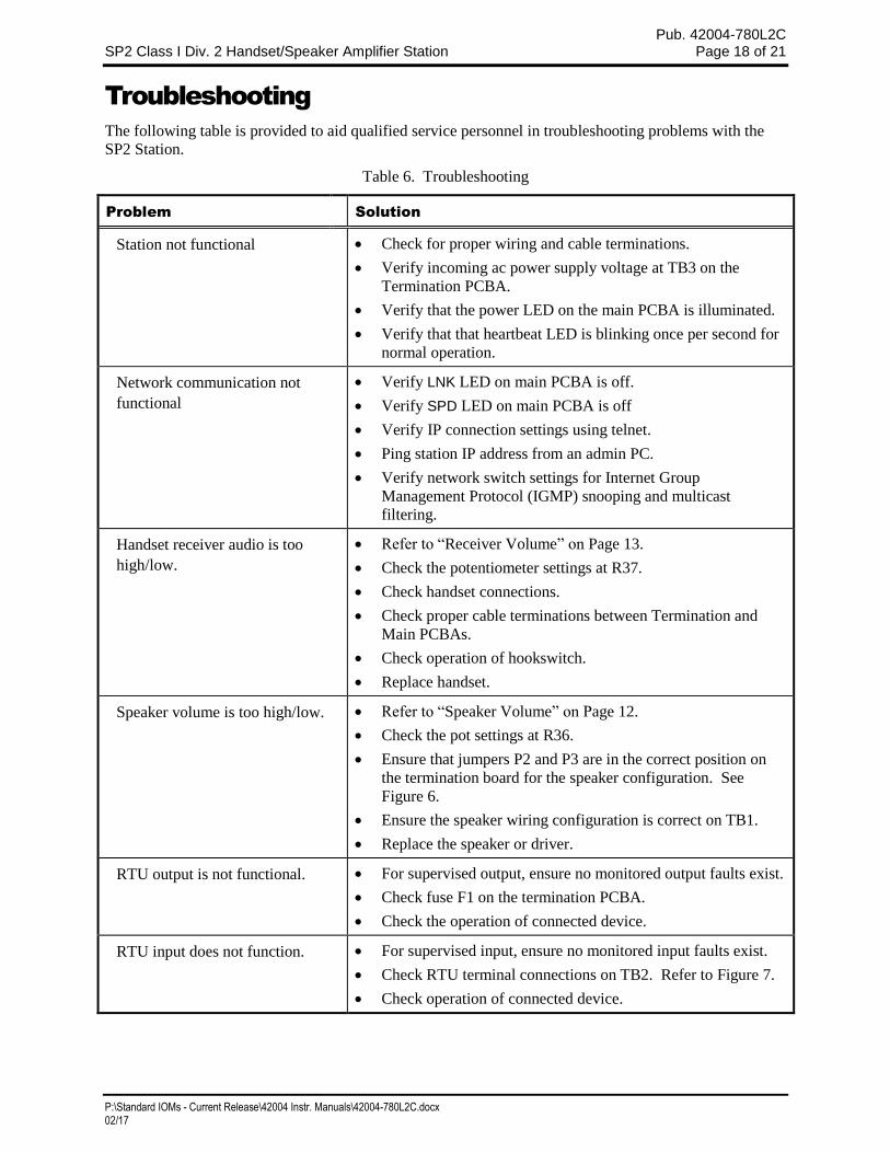
Troubleshooting
The following table is provided to aid qualified service personnel in troubleshooting problems with the
SP2 Station.
Table 6. Troubleshooting
Problem Solution
Station not functional Check for proper wiring and cable terminations.
Verify incoming ac power supply voltage at TB3 on the
Termination PCBA.
Verify that the power LED on the main PCBA is illuminated.
Verify that that heartbeat LED is blinking once per second for
normal operation.
Network communication not
functional
Verify LNK LED on main PCBA is off.
Verify SPD LED on main PCBA is off
Verify IP connection settings using telnet.
Ping station IP address from an admin PC.
Verify network switch settings for Internet Group
Management Protocol (IGMP) snooping and multicast
filtering.
Handset receiver audio is too
high/low.
Refer to “Receiver Volume” on Page 13.
Check the potentiometer settings at R37.
Check handset connections.
Check proper cable terminations between Termination and
Main PCBAs.
Check operation of hookswitch.
Replace handset.
Speaker volume is too high/low. Refer to “Speaker Volume” on Page 12.
Check the pot settings at R36.
Ensure that jumpers P2 and P3 are in the correct position on
the termination board for the speaker configuration. See
Figure 6.
Ensure the speaker wiring configuration is correct on TB1.
Replace the speaker or driver.
RTU output is not functional. For supervised output, ensure no monitored output faults exist.
Check fuse F1 on the termination PCBA.
Check the operation of connected device.
RTU input does not function. For supervised input, ensure no monitored input faults exist.
Check RTU terminal connections on TB2. Refer to Figure 7.
Check operation of connected device.
Pub. 42004-780L2C SP2 Class I Div. 2 Handset/Speaker Amplifier Station Page 19 of 21
P:\Standard IOMs - Current Release\42004 Instr. Manuals\42004-780L2C.docx 02/17
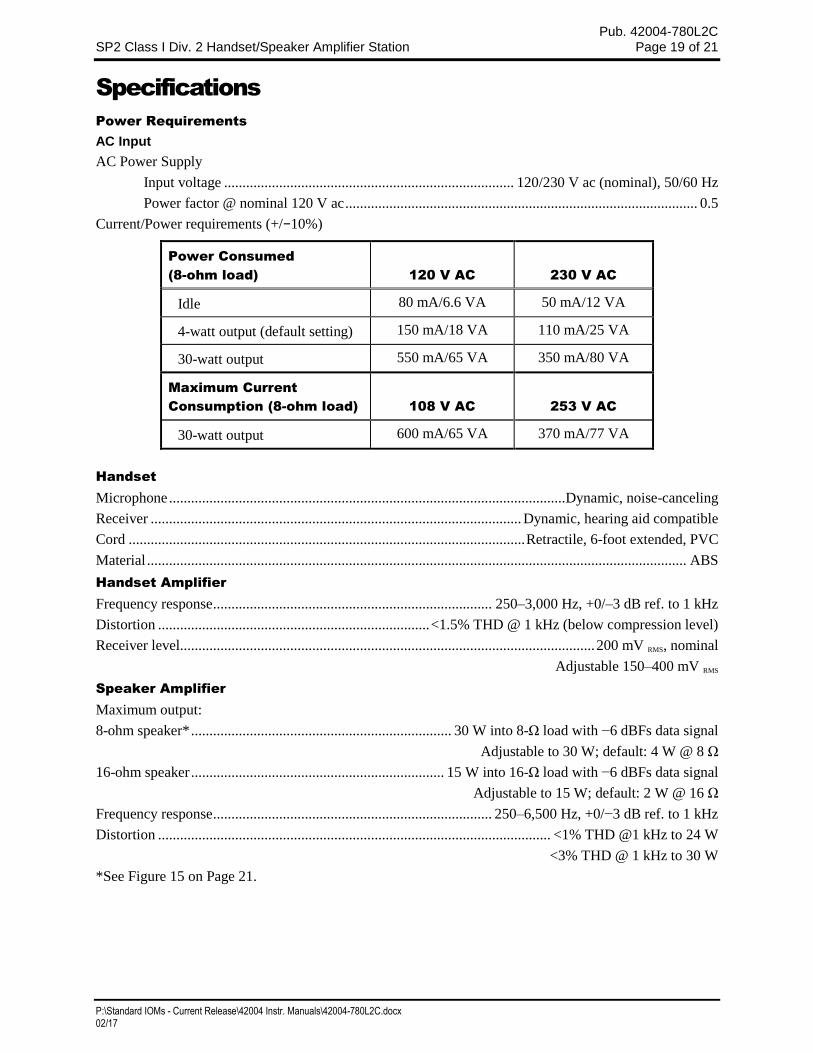
Specifications
Power Requirements
AC Input
AC Power Supply
Input voltage ............................................................................... 120/230 V ac (nominal), 50/60 Hz
Power factor @ nominal 120 V ac ................................................................................................ 0.5
Current/Power requirements (+/−10%)
Power Consumed
(8-ohm load) 120 V AC 230 V AC
Idle 80 mA/6.6 VA 50 mA/12 VA
4-watt output (default setting) 150 mA/18 VA 110 mA/25 VA
30-watt output 550 mA/65 VA 350 mA/80 VA
Maximum Current
Consumption (8-ohm load) 108 V AC 253 V AC
30-watt output 600 mA/65 VA 370 mA/77 VA
Handset
Microphone ............................................................................................................ Dynamic, noise-canceling
Receiver ..................................................................................................... Dynamic, hearing aid compatible
Cord ............................................................................................................ Retractile, 6-foot extended, PVC
Material ................................................................................................................................................... ABS
Handset Amplifier
Frequency response ............................................................................ 250–3,000 Hz, +0/–3 dB ref. to 1 kHz
Distortion .......................................................................... <1.5% THD @ 1 kHz (below compression level)
Receiver level................................................................................................................. 200 mV RMS, nominal
Adjustable 150–400 mV RMS
Speaker Amplifier
Maximum output:
8-ohm speaker* ....................................................................... 30 W into 8-Ω load with −6 dBFs data signal
Adjustable to 30 W; default: 4 W @ 8 Ω
16-ohm speaker ..................................................................... 15 W into 16-Ω load with −6 dBFs data signal
Adjustable to 15 W; default: 2 W @ 16 Ω
Frequency response ............................................................................ 250–6,500 Hz, +0/−3 dB ref. to 1 kHz
Distortion ........................................................................................................... <1% THD @1 kHz to 24 W
<3% THD @ 1 kHz to 30 W
*See Figure 15 on Page 21.
Pub. 42004-780L2C SP2 Class I Div. 2 Handset/Speaker Amplifier Station Page 20 of 21
P:\Standard IOMs - Current Release\42004 Instr. Manuals\42004-780L2C.docx 02/17
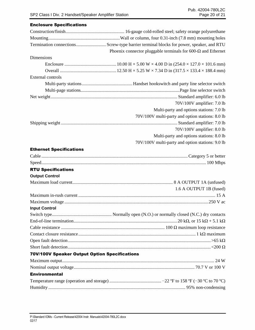
Enclosure Specifications
Construction/finish ................................................... 16-gauge cold-rolled steel; safety orange polyurethane
Mounting .............................................................. Wall or column, four 0.31-inch (7.8 mm) mounting holes
Termination connections .......................... Screw-type barrier terminal blocks for power, speaker, and RTU
Phoenix connector pluggable terminals for 600-Ω and Ethernet
Dimensions
Enclosure ............................................. 10.00 H × 5.00 W × 4.00 D in (254.0 × 127.0 × 101.6 mm)
Overall ................................................. 12.50 H × 5.25 W × 7.34 D in (317.5 × 133.4 × 188.4 mm)
External controls
Multi-party stations ............................................ Handset hookswitch and party line selector switch
Multi-page stations...................................................................................... Page line selector switch
Net weight .............................................................................................................. Standard amplifier: 6.0 lb
70V/100V amplifier: 7.0 lb
Multi-party and options stations: 7.0 lb
70V/100V multi-party and option stations: 8.0 lb
Shipping weight ..................................................................................................... Standard amplifier: 7.0 lb
70V/100V amplifier: 8.0 lb
Multi-party and options stations: 8.0 lb
70V/100V multi-party and option stations: 9.0 lb
Ethernet Specifications
Cable ............................................................................................................................... Category 5 or better
Speed ............................................................................................................................................... 100 Mbps
RTU Specifications
Output Control
Maximum load current ....................................................................................... 8 A OUTPUT 1A (unfused)
1.6 A OUTPUT 1B (fused)
Maximum in-rush current ....................................................................................................................... 15 A
Maximum voltage ............................................................................................................................. 250 V ac
Input Control
Switch type.................................................... Normally open (N.O.) or normally closed (N.C.) dry contacts
End-of-line termination .......................................................................................... 20 kΩ, or 15 kΩ + 5.1 kΩ
Cable resistance .......................................................................................... 100 Ω maximum loop resistance
Contact closure resistance ...................................................................................................... 1 kΩ maximum
Open fault detection ............................................................................................................................ >65 kΩ
Short fault detection ............................................................................................................................ <200 Ω
70V/100V Speaker Output Option Specifications
Maximum output .................................................................................................................................... 24 W
Nominal output voltage ......................................................................................................... 70.7 V or 100 V
Environmental
Temperature range (operation and storage) ............................................. −22 ºF to 158 ºF (−30 ºC to 70 ºC)
Humidity ....................................................................................................................... 95% non-condensing
Pub. 42004-780L2C SP2 Class I Div. 2 Handset/Speaker Amplifier Station Page 21 of 21
P:\Standard IOMs - Current Release\42004 Instr. Manuals\42004-780L2C.docx 02/17
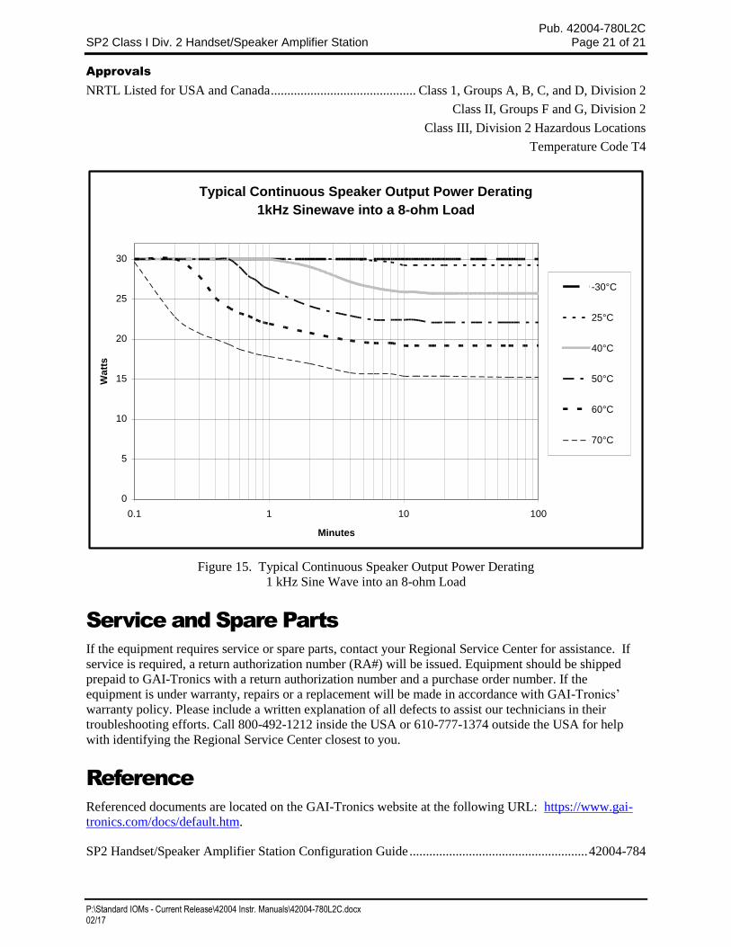
Approvals
NRTL Listed for USA and Canada ............................................ Class 1, Groups A, B, C, and D, Division 2
Class II, Groups F and G, Division 2
Class III, Division 2 Hazardous Locations
Temperature Code T4
Figure 15. Typical Continuous Speaker Output Power Derating
1 kHz Sine Wave into an 8-ohm Load
Service and Spare Parts
If the equipment requires service or spare parts, contact your Regional Service Center for assistance. If
service is required, a return authorization number (RA#) will be issued. Equipment should be shipped
prepaid to GAI-Tronics with a return authorization number and a purchase order number. If the
equipment is under warranty, repairs or a replacement will be made in accordance with GAI-Tronics’
warranty policy. Please include a written explanation of all defects to assist our technicians in their
troubleshooting efforts. Call 800-492-1212 inside the USA or 610-777-1374 outside the USA for help
with identifying the Regional Service Center closest to you.
Reference
Referenced documents are located on the GAI-Tronics website at the following URL: https://www.gai-
tronics.com/docs/default.htm.
SP2 Handset/Speaker Amplifier Station Configuration Guide ...................................................... 42004-784
Typical Continuous Speaker Output Power Derating
1kHz Sinewave into a 8-ohm Load
0
5
10
15
20
25
30
0.1 1 10 100
Minutes
Wa
tts
-30°C
25°C
40°C
50°C
60°C
70°C
(Rev. 10/06)
WarrantyEquipment. GAI-Tronics warrants for a period of one (1) year from the date of shipment, that anyGAI-Tronics equipment supplied hereunder shall be free of defects in material and workmanship, shallcomply with the then-current product specifications and product literature, and if applicable, shall be fitfor the purpose specified in the agreed upon quotation or proposal document. If (a) Seller’s goods proveto be defective in workmanship and/or material under normal and proper usage, or unfit for the purposespecified and agreed upon, and (b) Buyer’s claim is made within the warranty period set forth above,Buyer may return such goods to GAI-Tronics nearest depot repair facility, freight prepaid, at which timethey will be repaired or replaced, at Seller’s option, without charge to Buyer. Repair or replacement shallbe Buyer’s sole and exclusive remedy. The warranty period on any repaired or replacement equipmentshall be the greater of the ninety (90) day repair warranty or one (1) year from the date the originalequipment was shipped. In no event shall GAI-Tronics warranty obligations with respect to equipmentexceed 100% of the total cost of the equipment supplied hereunder. Buyer may also be entitled to themanufacturer’s warranty on any third-party goods supplied by GAI-Tronics hereunder. The applicabilityof any such third-party warranty will be determined by GAI-Tronics.
Services. Any services GAI-Tronics provides hereunder, whether directly or through subcontractors,shall be performed in accordance with the standard of care with which such services are normallyprovided in the industry. If the services fail to meet the applicable industry standard, GAI-Tronics will re-perform such services at no cost to buyer to correct said deficiency to Company's satisfaction providedany and all issues are identified prior to the demobilization of the Contractor's personnel from the worksite. Re-performance of services shall be Buyer's sole and exclusive remedy, and in no event shall GAI-Tronics warranty obligations with respect to services exceed 100% of the total cost of the servicesprovided hereunder.
Warranty Periods. Every claim by Buyer alleging a defect in the goods and/or services providedhereunder shall be deemed waived unless such claim is made in writing within the applicable warrantyperiods as set forth above. Provided, however, that if the defect complained of is latent and notdiscoverable within the above warranty periods, every claim arising on account of such latent defect shallbe deemed waived unless it is made in writing within a reasonable time after such latent defect is orshould have been discovered by Buyer.
Limitations / Exclusions. The warranties herein shall not apply to, and GAI-Tronics shall not beresponsible for, any damage to the goods or failure of the services supplied hereunder, to the extentcaused by Buyer’s neglect, failure to follow operational and maintenance procedures provided with theequipment, or the use of technicians not specifically authorized by GAI-Tronics to maintain or service theequipment. THE WARRANTIES AND REMEDIES CONTAINED HEREIN ARE IN LIEU OF ANDEXCLUDE ALL OTHER WARRANTIES AND REMEDIES, WHETHER EXPRESS OR IMPLIED BYOPERATION OF LAW OR OTHERWISE, INCLUDING ANY WARRANTIES OFMERCHANTABILITY OR FITNESS FOR A PARTICULAR PURPOSE.
Return PolicyIf the equipment requires service, contact your Regional Service Center for a return authorization number(RA#). Equipment should be shipped prepaid to GAI-Tronics with a return authorization number and apurchase order number. If the equipment is under warranty, repairs or a replacement will be made inaccordance with the warranty policy set forth above. Please include a written explanation of all defects toassist our technicians in their troubleshooting efforts.
Call 800-492-1212 (inside the USA) or 610-777-1374 (outside the USA) for help identifying theRegional Service Center closest to you.