sp1000 series - powermetricsintl.com · sp1000 series field installation manual revision 1 march...
TRANSCRIPT

SP1000 Series Field Installation Manual
Revision 1 March 09, 2013 – Initial issue Revision 2 August 01, 2014 – Updates Revision 3 September 28, 2015 – Updates
To prevent electrical shock and/or equipment damage, disconnect electric power to system at main fuse or circuit breaker box until installation is complete.
Do not use on circuits exceeding specified voltage. Higher voltage will damage control and could cause shock or fire hazard.
Do not short out terminals primary control to test. Short or incorrect wiring could cause personal injury, death and/or property damage.
Electrical installation and all components of the system shall conform to Class II circuits per the NEC code.
OPERATOR (Customer): SAVE THESE INSTRUCTIONS FOR FUTURE USE.
FAILURE TO READ AND FOLLOW ALL INSTRUCTIONS CAREFULLY BEFORE INSTALLING OR OPERATING THE SP1000 WILL VOID WARRANTY AND COULD CAUSE SERIOUS PERSONAL INURY, DEATH AND/OR PROPERTY DAMAGE.
CAUTION PRECAUTION

SP1000 480 MODEL ELECTRICAL DATA
Model SP1000E SP1000E2 SP1000E3 SP1000E7 SP1000E8 Panel Voltage 480 Vac Panel Voltage per Phase 277 Vac 277 Vac Neutral Line required Yes No Yes No Phases/Configuration 3Ø/WYE format Frequency 60 Hz KVAR Total Rating 28 21 21 24 24 KVAR Rating per Phase 9.3 7 7 8 8 Total Capacitance per phase 320 µF 240 µF 240 µF 280 µF 280 µF Fixed bank Capacitance per phase 120 µF 0 40 µF 0 40 µF Maximum BRANCH Circuit Current Rating 40 Amps (Optional secondary protection breaker on the SP1000) Maximum Ambient Temperature Rating 50 ⁰C Enclosure Dimension 24”x18”x11 1/4”
SP1000 380 MODEL ELECTRICAL DATA
Model SP1000C SP1000D SP1000D2 Panel Voltage 380 Vac Panel Voltage per Phase 220 Vac Neutral Line required Yes No Phases/Configuration 3Ø/WYE format Frequency 60 Hz KVAR Total Rating 10 20 KVAR Rating per Phase 3.33 6.66 Total Capacitance per phase 180 µF 360 µF Fixed bank Capacitance per phase 0 0 60 µF Maximum BRANCH Circuit Current Rating 30 Amps 40 Amps Maximum Ambient Temperature Rating 50 ⁰C Enclosure Dimension 17”x12 1/2”x6 1/2” 24”x18”x11 1/4”
SP1000 208 MODEL ELECTRICAL DATA
Model SP1000A SP1000A2 SP1000B SP1000B2 Panel Voltage 208 Vac Panel Voltage per Phase 120 Vac 120 Vac Neutral Line required Yes No Yes No Phases/Configuration 3Ø/DELTA format Frequency 60 Hz KVAR Total Rating 9 18 KVAR Rating per Phase 3 6 Total Capacitance per phase 180 µF 360 µF Fixed bank Capacitance per phase 0 Maximum BRANCH Circuit Current Rating 30 Amps 60 Amps Maximum Ambient Temperature Rating 50 ⁰C Enclosure Dimension 17”x12 1/2”x6 1/2” 24”x18”x11 1/4”
SP1000 Family Snapshot

INDEX
Section1: Instructions for Installation of SP1000
Section 2:
2.1 Instructions for Connection of the SP1000 to Customer Sub Panel
2.2 Instructions for Connection of the SP1000 using a new Disconnect
Switch
Section 3:
3.1 Instructions for Installation of External Current Transformers
3.2 Location of current Transformer at customer Sub Panel
Section 4: SP1000 DATA SHEETS
Section 5: Electrical installation Diagrams
Section 6: Recommended Parts List
Section 7: Parameter Display Glossary and Definitions
Return Policy
Warranty
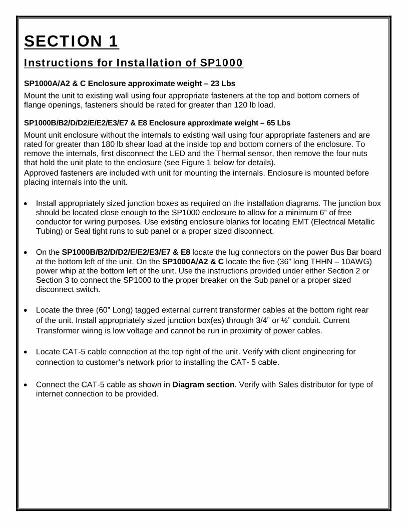
SECTION 1 Instructions for Installation of SP1000
SP1000A/A2 & C Enclosure approximate weight – 23 Lbs Mount the unit to existing wall using four appropriate fasteners at the top and bottom corners of flange openings, fasteners should be rated for greater than 120 lb load.
SP1000B/B2/D/D2/E/E2/E3/E7 & E8 Enclosure approximate weight – 65 Lbs Mount unit enclosure without the internals to existing wall using four appropriate fasteners and are rated for greater than 180 lb shear load at the inside top and bottom corners of the enclosure. To remove the internals, first disconnect the LED and the Thermal sensor, then remove the four nuts that hold the unit plate to the enclosure (see Figure 1 below for details). Approved fasteners are included with unit for mounting the internals. Enclosure is mounted before placing internals into the unit.
Install appropriately sized junction boxes as required on the installation diagrams. The junction box should be located close enough to the SP1000 enclosure to allow for a minimum 6” of free conductor for wiring purposes. Use existing enclosure blanks for locating EMT (Electrical Metallic Tubing) or Seal tight runs to sub panel or a proper sized disconnect.
On the SP1000B/B2/D/D2/E/E2/E3/E7 & E8 locate the lug connectors on the power Bus Bar board at the bottom left of the unit. On the SP1000A/A2 & C locate the five (36” long THHN – 10AWG) power whip at the bottom left of the unit. Use the instructions provided under either Section 2 or Section 3 to connect the SP1000 to the proper breaker on the Sub panel or a proper sized disconnect switch.
Locate the three (60” Long) tagged external current transformer cables at the bottom right rear of the unit. Install appropriately sized junction box(es) through 3/4” or ½” conduit. Current Transformer wiring is low voltage and cannot be run in proximity of power cables.
Locate CAT-5 cable connection at the top right of the unit. Verify with client engineering for connection to customer’s network prior to installing the CAT- 5 cable.
Connect the CAT-5 cable as shown in Diagram section. Verify with Sales distributor for type of internet connection to be provided.

For the SP1000B/B2/D/D2/E/E2/E3/E7 & E8 only: Mount unit enclosure without the internals to existing wall using four appropriate fasteners and are rated for greater than 180 lb shear load at the inside top and bottom corners of the enclosure. To remove the internals, first disconnect the LED and the Thermal sensor, then remove the four nuts that hold the unit plate to the enclosure (see Figure 1 below for details).
Figure 1 Enclosure Detail
Internals Nuts
Thermal sensor
Connector
LED connector
CAT-5 connector

SECTION # 2 2.1 Instructions for Connection of the SP1000 to Customer Sub Panel
The SP1000E/E2/E7 & E8 units are designed for use with Customer Sub Panel – operating at 277/480 Volts (“Y”) WYE, 3 Phase 100 to 400 Amp panel with neutral bar.
The SP1000E3 & E8 units are designed for use with Customer Sub Panel – operating at 480 Volts, 3 Phase 100 to 400 Amp panel without neutral bar.
An optional 40 amp secondary protection breaker can be installed on the SP1000 480 version at the factory as per customer request.
The SP1000C & D units are designed for use with Customer Sub Panel – operating at 220/380 Volts (“Y”) WYE, 3 Phase 100 to 400 Amp panel with neutral bar.
The SP1000 D2 unit is designed for use with Customer Sub Panel – operating at 380 Volts, 3 Phase 100 to 400 Amp panel without neutral bar.
The SP1000A & B units are designed for use with Customer Sub Panel – operating at 120/208 Volts (“Δ”) DELTA, 3 Phase 100 to 400 Amp panel with neutral bar.
The SP1000A2 & B2 units are designed for use with Customer Sub Panel – operating at 208/240 Volts, 3 Phase 100 to 400 Amp panel without neutral bar.
1. Remove sub panel covers exposing internal wiring and breakers (Review Diagram section – Section 5 - for Sub Panel Wiring SP1000 Installation).
2. Locate earth ground connection to panel grounding bar/or to earth ground rod. Connect a green earth cable from the SP1000 to customer sub panel earth ground bar. Use existing power cable connector for grounding cable. Ensure all mechanical connections are secure and making full contact.
3. Make sure the ground is truly connected to the supply transformer.
4. Mount the three phase appropriate circuit breaker for the SP1000 model to be installed. During installation verify proper color code on feed cables into sub panel.
A. Connect a Brown or Black wire from the SP1000 L1 connection to Customer Sub Panel L1 on the breaker.
B. Connect an Orange or Red wire from the SP1000 L2 connection to Customer Sub Panel L2 on the

breaker.
C. Connect a Yellow or Blue wire from the SP1000 L3 connection to Customer Sub Panel L3 on the breaker.
D. Connect a Gray or White wire from the SP1000 N connection to Customer Sub Panel Neutral Bar. E. Connect a Green wire from the SP1000 ground connection to Customer Sub Panel Ground bar or
Grounding Rod.
Note 1: A junction box is needed for the models SP1000A, A2 and C for the power wires connections.
5. Install three split core Current Transformers as required (on the feed side or on the load side) of customers sub panel (one per phase - see Section 3). Verify that the arrows on the transformers point towards the direction of the Load. All Current Transformers shall meet the following:
Transformers are for connection only to UL Listed energy usage monitoring current transformers.
Recommend using 22 AWG stranded (7x30) TC conductors, polypropylene insulation, paper wrap, twisted pair, overall Beldfoil shield (100% coverage), TC drain wire, PVC jacket.
6. Qualified Representative to inspect line side of sub panel to determine correct AWG cable size for correct mounting of (3) external current Transformers on 350MCM/500MCM Cables.
Note 2: A junction box is needed on all SP1000 models for the CT wires connections.
All cables are attached to SP1000 unit (install cables per local electrical codes and utilize approved IEEE standards and UL rated components.
Earth ground to be connected from SP1000 ground cable to sub panel earth ground rod.
All external connections and additional work must be performed by a qualified representative in accordance to state and local codes.
All materials used must conform to the NEC and meet all applicable UL standards.
Failure to comply will void warranty.
NOTE

2.2 Instructions for Connection of the SP1000 using a new Disconnect Switch Use a Disconnect when there is not space at customer Sub Panel or the SP1000 will be connected close to the Load.
Representative must purchase the correct current and voltage rating three phases Blade-Fused Disconnect Switch or equal for connection of the SP1000.
The SP1000E/E2/E7 & E8 units are designed for use with Customer Sub Panel – operating at 277/480 Volts (“Y”) WYE, 3 Phase 100 to 400 Amp panel with neutral bar.
The SP1000E3 & E8 units are designed for use with Customer Sub Panel – operating at 480 Volts, 3 Phase 100 to 400 Amp panel without neutral bar.
An optional 40 amp secondary protection breaker can be installed on the SP1000 480 version at the factory as per customer request.
The SP1000C & D units are designed for use with Customer Sub Panel – operating at 220/380 Volts (“Y”) WYE, 3 Phase 100 to 400 Amp panel with neutral bar.
The SP1000 D2 unit is designed for use with Customer Sub Panel – operating at 380 Volts, 3 Phase 100 to 400 Amp panel without neutral bar.
The SP1000A & B units are designed for use with Customer Sub Panel – operating at 120/208 Volts (“Δ”) DELTA, 3 Phase 100 to 400 Amp panel with neutral bar.
The SP1000A2 & B2 units are designed for use with Customer Sub Panel – operating at 208/240 Volts, 3 Phase 100 to 400 Amp panel without neutral bar.
1. Install a new three phase Blade-Fused external disconnect switch to wall or existing back board. Qualified Representative should note if codes allow for direct connection to bus bars in sub panel or requires installation of an additional sub panel.
2. Remove sub panel covers exposing internal wiring and breakers (review the Installation Diagram - Section - section 5 - for Sub Panel Wiring SP1000).
3. Wire in rigid conduit or equal between customer’s sub panel and the external disconnect switch. Connect the disconnect enclosure to SP1000 using 3/4” conduit or equivalent.
4. Locate the Neutral connection of the SP1000 to panel grounding Neutral bar.
5. Locate earth ground connection of the SP1000 to panel grounding bar/or to earth ground rod.

6. When installing the power cable, do not use sensor connectors. Use knocks out at different location of customer sub panel.
7. Ensure all mechanical connections secure and making full contact
8. If a disconnect cannot be installed then a new sub panel will be required with the correct breaker for the SP1000 model to be installed.
All cables are attached to SP1000 unit (installed per cables per local electrical codes and utilize approved IEEE standards and UL rated components.
All external connections and additional work must be performed by a qualified representative in accordance to state and local codes.
All materials used must conform to the NEC and meet all applicable UL standards.
Failure to comply will void warranty.
NOTE

SECTION 3 3.1 Instructions for Installation of External Current Transformers
1. Locate the external current transformer whips at bottom right side of SP1000.
2. Connect junction box to existing conduit (See the Installation Diagram section).
3. Connect current transformer 60” Long whip to the Split Core Current Transformer to be installed on the power wires of the customer panel in accordance with state and local codes. See the Installation Diagram 5 for optional connections of external current transformers.
Three external Current Transformers are for connection only per UL Listed energy usage monitoring current transformers.
4. Firmly secure each current transformer to Feed Side or Load side cables in sub panel cables. Insure that the phases are correct as compared to the color code. SP1000 requires that the correct phase corresponds with the correct current transformer.
CT 1 to L1 Brown or Black CT 2 to L2 Orange or Red CT 3 to L3 Yellow or Blue
5. Insure current transformers are separated from each other and firmly secured to cable using plastic tie-wraps or alternate approved method. Each current transformer is installed with arrows facing toward the load.
(See the Installation Diagram section).
Current Transformer wiring is low voltage and cannot be run in proximity to sub panel high voltage cables. During installation if practical the three transformer cables should be encased in their own EMT or Seal tight.
Current transformers sizes used for sampling current during calibration by PMI are as follows: Wire sizes under 350MCM – Small current Transformer CT302S300 Wires sizes between 350MCN and 500MCM – large current Transformer
CT302F300 CT supplied by other must maintain identical characteristics.
PMI sets calibration at the factory using the above Current Transformers. If the factory current transformers are replaced by others during field installation, re-calibration may be required.
Failure to comply will void warranty.
NOTE 1

3.2 Location of current Transformer at customer Sub Panel
1. Existing Sub Panel: a. Placing the current transformers at a sub panel when the SP1000 is connected to a breaker,
the transformers can be placed at the feed cables entering the panel or at the load cables coming out of the panel to the Load. The transformer marking (Arrow) faces toward the Load.
b. Secure the current transformer to each phase with the suitable material ( Wire Ties) to keep the current transformer in place without coming in contact with any other materials (Do not have the current transformer resting on the main breaker).
c. Current Transformer wires are connected to: 22 – 26 AWG insulated stranded wire using appropriate wire nuts.
d. Current Transformer wires are low voltage and must be segregated from other power cables. NEC separation criteria are recommended.
e. When installing the split core current transformer it is important to connect wires at: Phase one to marked phase one on lead from SP1000 unit (Do not cross phases). Phase two to marked phase two on lead from SP1000 (Do not cross phases). Phase three to marked phase three on lead from SP1000 (Do not cross phases).
f. Polarity of transformer’s is critical for proper connection (see below); White – Common Black – Signal
2. Existing Disconnect Switch: a. When installing the SP1000 unit and using a disconnect or other devices the current
transformer should always be placed on the cables facing toward the load.
TESTING- Correct phasing is extremely important to ensure proper performance of the SP1000, each phase, correct connection can be verified by confirming the Current Transformer output at the unit display. Select phase 1 and disconnect wire nut and phase 1 will read zero. Repeat this process for phase 3. If zero is not achieved you have a phase shift which must be corrected.
PMI requires installation of the SP1000 be in accordance with the National Electric Code ( Latest Edition), and local and state governing codes be adhered to.
PMI assumes no responsibility for incorrect installation or when supplied current transformers are not installed.
NOTE 2

SECTION 4 SP1000 DATA SHEETS
SP1000E
Model SP 1000 Family –Series - 1000 – SP1000E Unit
Phase Configuration (277/480 3Ø “WYE” format) L1-Brown, L2-Orange, L3-Yellow, Neutral – Gray, Ground – Green
Panel Voltage 277/480 Volts
Total Capacitance rated up to 320µF per phase/120µF fixed/200µF switchable
Monitoring capabilities Metering for monitoring PF, I, V,KVAR, and THD
KVAR performance range 10 to 28 per phase
Frequency 60 Hertz
Typical Protection (See Note*) Electrical Storms, Lightning Activity and Power Utility Spikes (Units are not intended to take the place of designed Power Surge Equipment)
Protected Capacitors evaluated to 10,000 AFC per UL-810 Lighting strike protection (See Note*)
Metal Oxide Varistors - with Transient Voltage Suppressors on separate MOV board for internal use only.
Circuit Breaker Required 40A - 3 Ø Breaker or NEC approved isolation device (External to unit) An internal secondary 40A-3 Ø breaker can be installed on the SP1000E per customer request.
Low losses 1 watt per kVAR Dissipation Factor 0.1% at 60 Hz and 25 C, 1% at 1,000 Hz and 25 C Insulation Resistance 500 M Ohms per µF
Human Protection Capacitor terminals isolated from human contact. Discharge resistors on capacitors.
Operating temperature range Capacitors -16° C to +70° C (Unit rating ambient temperature at 50° C) Dimensions (LxHxD) 24” x 18” x 11 1/4” Metal Enclosure UL Listed Operating Life 60,000 hours with >94% survival (Capacitors switched by
electronics in separate bank configuration) General Enclosure UL Listed NEMA -1 Enclosure 16 Ga. H.R.P. & O. (1.4mm) Wire Rating: 600 Volts THHN - Gasoline & Oil Resistant 11 Wire Gauge THHN - 8 Gauge wire Unit Weight 65 lbs
Note (*): not evaluated by UL

SP1000E2
Model SP 1000 Family –Series - 1000 – SP1000E2 Unit
Phase Configuration (277/480 3Ø “WYE” format) L1-Brown, L2-Orange, L3-Yellow, Neutral – Gray, Ground – Green
Panel Voltage 277/480 Volts
Total Capacitance rated up to 240µF per phase switchable
Monitoring capabilities Metering for monitoring PF, I, V,KVAR, and THD
KVAR performance range 0 to 21 per phase
Frequency 60 Hertz
Typical Protection (See Note*) Electrical Storms, Lightning Activity and Power Utility Spikes (Units are not intended to take the place of designed Power Surge Equipment)
Protected Capacitors evaluated to 10,000 AFC per UL-810 Lighting strike protection (See Note*)
Metal Oxide Varistors - with Transient Voltage Suppressors on separate MOV board for internal use only.
Circuit Breaker Required 40A - 3 Ø Breaker or NEC approved isolation device (External to unit) An internal secondary 40A-3 Ø breaker can be installed on the SP1000E2 per customer request. Low losses 1 watt per kVAR
Dissipation Factor 0.1% at 60 Hz and 25 C, 1% at 1,000 Hz and 25 C Insulation Resistance 500 M Ohms per µF
Human Protection Capacitor terminals isolated from human contact. Discharge resistors on capacitors.
Operating temperature range Capacitors -16° C to +70° C (Unit rating ambient temperature at 50° C) Dimensions (LxHxD) 24” x 18” x 11 1/4” Metal Enclosure UL Listed Operating Life 60,000 hours with >94% survival (Capacitors switched by
electronics in separate bank configuration) General Enclosure UL Listed NEMA -1 Enclosure 16 Ga. H.R.P. & O. (1.4mm) Wire Rating: 600 Volts THHN - Gasoline & Oil Resistant 11 Wire Gauge THHN - 8 Gauge wire Unit Weight 65 lbs
Note (*): not evaluated by UL

SP1000E3
Model SP 1000 Family –Series - 1000 – SP1000E3 Unit
Phase Configuration (480 3Ø ) L1-Brown, L2-Orange, L3-Yellow, Ground – Green
Panel Voltage 480 Volts
Total Capacitance rated up to 240µF per phase/40µF fixed/200µF switchable
Monitoring capabilities Metering for monitoring PF, I, V,KVAR, and THD
KVAR performance range 3.5 to 21 per phase
Frequency 60 Hertz
Typical Protection (See Note*) Electrical Storms, Lightning Activity and Power Utility Spikes (Units are not intended to take the place of designed Power Surge Equipment)
Protected Capacitors evaluated to 10,000 AFC per UL-810 Lighting strike protection (See Note*)
Metal Oxide Varistors - with Transient Voltage Suppressors on separate MOV board for internal use only.
Circuit Breaker Required 40A - 3 Ø Breaker or NEC approved isolation device (External to unit) An internal secondary 40A-3 Ø breaker can be installed on the SP1000E3 per customer request. Low losses 1 watt per kVAR
Dissipation Factor 0.1% at 60 Hz and 25 C, 1% at 1,000 Hz and 25 C Insulation Resistance 500 M Ohms per µF
Human Protection Capacitor terminals isolated from human contact. Discharge resistors on capacitors.
Operating temperature range Capacitors -16° C to +70° C (Unit rating ambient temperature at 50° C) Dimensions (LxHxD) 24” x 18” x 11 1/4” Metal Enclosure UL Listed Operating Life 60,000 hours with >94% survival (Capacitors switched by
electronics in separate bank configuration) General Enclosure UL Listed NEMA -1 Enclosure 16 Ga. H.R.P. & O. (1.4mm) Wire Rating: 600 Volts THHN - Gasoline & Oil Resistant 11 Wire Gauge THHN - 8 Gauge wire Unit Weight 65 lbs
Note (*): not evaluated by UL

SP1000E7
Model SP 1000 Family –Series - 1000 – SP1000E7 Unit
Phase Configuration (277/480 3Ø “WYE” format) L1-Brown, L2-Orange, L3-Yellow, Neutral – Gray, Ground – Green
Panel Voltage 277/480 Volts
Total Capacitance rated up to 280µF per phase switchable
Monitoring capabilities Metering for monitoring PF, I, V,KVAR, and THD
KVAR performance range 0 to 24 per phase
Frequency 60 Hertz
Typical Protection (See Note*) Electrical Storms, Lightning Activity and Power Utility Spikes (Units are not intended to take the place of designed Power Surge Equipment)
Protected Capacitors evaluated to 10,000 AFC per UL-810 Lighting strike protection (See Note*)
Metal Oxide Varistors - with Transient Voltage Suppressors on separate MOV board for internal use only.
Circuit Breaker Required 40A - 3 Ø Breaker or NEC approved isolation device (External to unit) An internal secondary 40A-3 Ø breaker can be installed on the SP1000E7 per customer request. Low losses 1 watt per kVAR
Dissipation Factor 0.1% at 60 Hz and 25 C, 1% at 1,000 Hz and 25 C Insulation Resistance 500 M Ohms per µF
Human Protection Capacitor terminals isolated from human contact. Discharge resistors on capacitors.
Operating temperature range Capacitors -16° C to +70° C (Unit rating ambient temperature at 50° C) Dimensions (LxHxD) 24” x 18” x 11 1/4” Metal Enclosure UL Listed Operating Life 60,000 hours with >94% survival (Capacitors switched by
electronics in separate bank configuration) General Enclosure UL Listed NEMA -1 Enclosure 16 Ga. H.R.P. & O. (1.4mm) Wire Rating: 600 Volts THHN - Gasoline & Oil Resistant 11 Wire Gauge THHN - 8 Gauge wire Unit Weight 65 lbs
Note (*): not evaluated by UL

SP1000E8
Model SP 1000 Family –Series - 1000 – SP1000E8 Unit
Phase Configuration (480 3Ø ) L1-Brown, L2-Orange, L3-Yellow, Ground – Green
Panel Voltage 480 Volts
Total Capacitance rated up to 280µF per phase/40µF fixed/240µF switchable
Monitoring capabilities Metering for monitoring PF, I, V,KVAR, and THD
KVAR performance range 3.5 to 24 per phase
Frequency 60 Hertz
Typical Protection (See Note*) Electrical Storms, Lightning Activity and Power Utility Spikes (Units are not intended to take the place of designed Power Surge Equipment)
Protected Capacitors evaluated to 10,000 AFC per UL-810 Lighting strike protection (See Note*)
Metal Oxide Varistors - with Transient Voltage Suppressors on separate MOV board for internal use only.
Circuit Breaker Required 40A - 3 Ø Breaker or NEC approved isolation device (External to unit) An internal secondary 40A-3 Ø breaker can be installed on the SP1000E8 per customer request. Low losses 1 watt per kVAR
Dissipation Factor 0.1% at 60 Hz and 25 C, 1% at 1,000 Hz and 25 C Insulation Resistance 500 M Ohms per µF
Human Protection Capacitor terminals isolated from human contact. Discharge resistors on capacitors.
Operating temperature range Capacitors -16° C to +70° C (Unit rating ambient temperature at 50° C) Dimensions (LxHxD) 24” x 18” x 11 1/4” Metal Enclosure UL Listed Operating Life 60,000 hours with >94% survival (Capacitors switched by
electronics in separate bank configuration) General Enclosure UL Listed NEMA -1 Enclosure 16 Ga. H.R.P. & O. (1.4mm) Wire Rating: 600 Volts THHN - Gasoline & Oil Resistant 11 Wire Gauge THHN - 8 Gauge wire Unit Weight 65 lbs
Note (*): not evaluated by UL

SP1000D
Model SP 1000 Family –Series - 1000 – SP1000D Unit
Phase Configuration (220/380 3Ø “WYE” format) L1-Brown, L2-Orange, L3-Yellow, Neutral – Gray, Ground – Green
Panel Voltage 220/380 Volts
Total Capacitance rated up to 360µF per phase switchable
Monitoring capabilities Metering for monitoring PF, I, V,KVAR, and THD
KVAR performance range 0 to 20 per phase
Frequency 60 Hertz
Typical Protection (See Note*) Electrical Storms, Lightning Activity and Power Utility Spikes (Units are not intended to take the place of designed Power Surge Equipment)
Protected Capacitors evaluated to 10,000 AFC per UL-810 Lighting strike protection (See Note*)
Metal Oxide Varistors - with Transient Voltage Suppressors on separate MOV board for internal use only.
Circuit Breaker Required 40A - 3 Ø Breaker or NEC approved isolation device (External to unit) Low losses 1 watt per kVAR Dissipation Factor 0.1% at 60 Hz and 25 C, 1% at 1,000 Hz and 25 C Insulation Resistance 500 M Ohms per µF
Human Protection Capacitor terminals isolated from human contact. Discharge resistors on capacitors.
Operating temperature range Capacitors -16° C to +70° C (Unit rating ambient temperature at 50° C) Dimensions (LxHxD) 24” x 18” x 11 1/4” Metal Enclosure UL Listed Operating Life 60,000 hours with >94% survival (Capacitors switched by
electronics in separate bank configuration) General Enclosure UL Listed NEMA -1 Enclosure 16 Ga. H.R.P. & O. (1.4mm) Wire Rating: 600 Volts THHN - Gasoline & Oil Resistant 11 Wire Gauge THHN - 8 Gauge wire Unit Weight 65 lbs
Note (*): not evaluated by UL

SP1000D2
Model SP 1000 Family –Series - 1000 – SP1000D2 Unit
Phase Configuration (380 3Ø ) L1-Brown, L2-Orange, L3-Yellow, Ground – Green
Panel Voltage 380 Volts
Total Capacitance rated up to 360µF per phase/60µF fixed/300µF switchable
Monitoring capabilities Metering for monitoring PF, I, V,KVAR, and THD
KVAR performance range 3.3 to 20 per phase
Frequency 60 Hertz
Typical Protection (See Note*) Electrical Storms, Lightning Activity and Power Utility Spikes (Units are not intended to take the place of designed Power Surge Equipment)
Protected Capacitors evaluated to 10,000 AFC per UL-810 Lighting strike protection (See Note*)
Metal Oxide Varistors - with Transient Voltage Suppressors on separate MOV board for internal use only.
Circuit Breaker Required 40A - 3 Ø Breaker or NEC approved isolation device (External to unit) Low losses 1 watt per kVAR Dissipation Factor 0.1% at 60 Hz and 25 C, 1% at 1,000 Hz and 25 C Insulation Resistance 500 M Ohms per µF
Human Protection Capacitor terminals isolated from human contact. Discharge resistors on capacitors.
Operating temperature range Capacitors -16° C to +70° C (Unit rating ambient temperature at 50° C) Dimensions (LxHxD) 24” x 18” x 11 1/4” Metal Enclosure UL Listed Operating Life 60,000 hours with >94% survival (Capacitors switched by
electronics in separate bank configuration) General Enclosure UL Listed NEMA -1 Enclosure 16 Ga. H.R.P. & O. (1.4mm) Wire Rating: 600 Volts THHN - Gasoline & Oil Resistant 11 Wire Gauge THHN - 8 Gauge wire Unit Weight 65 lbs
Note (*): not evaluated by UL

SP1000C
Model SP 1000 Family –Series - 1000 – SP1000C Unit
Phase Configuration (220/380 3Ø “WYE” format) L1-Black, L2-Red, L3-Blue, Neutral – White, Ground – Green
Panel Voltage 220/380 Volts
Total Capacitance rated up to 180µF per phase switchable
Monitoring capabilities Metering for monitoring PF, I, V,KVAR, and THD
KVAR performance range 0 to 10 per phase
Frequency 60 Hertz
Typical Protection (See Note*) Electrical Storms, Lightning Activity and Power Utility Spikes (Units are not intended to take the place of designed Power Surge Equipment)
Protected Capacitors evaluated to 10,000 AFC per UL-810 Lighting strike protection (See Note*)
Metal Oxide Varistors - with Transient Voltage Suppressors on separate MOV board for internal use only.
Circuit Breaker Required 40A - 3 Ø Breaker or NEC approved isolation device (External to unit) Low losses 1 watt per kVAR Dissipation Factor 0.1% at 60 Hz and 25 C, 1% at 1,000 Hz and 25 C Insulation Resistance 500 M Ohms per µF
Human Protection Capacitor terminals isolated from human contact. Discharge resistors on capacitors.
Operating temperature range Capacitors -16° C to +70° C (Unit rating ambient temperature at 50° C) Dimensions (LxHxD) 17” x 12 1/2” x 6 1/2” Metal Enclosure UL Listed Operating Life 60,000 hours with >94% survival (Capacitors switched by
electronics in separate bank configuration) General Enclosure UL Listed NEMA -1 Enclosure 16 Ga. H.R.P. & O. (1.4mm) Wire Rating: 600 Volts THHN - Gasoline & Oil Resistant 11 Wire Gauge THHN - 8 Gauge wire Unit Weight 23 lbs
Note (*): not evaluated by UL
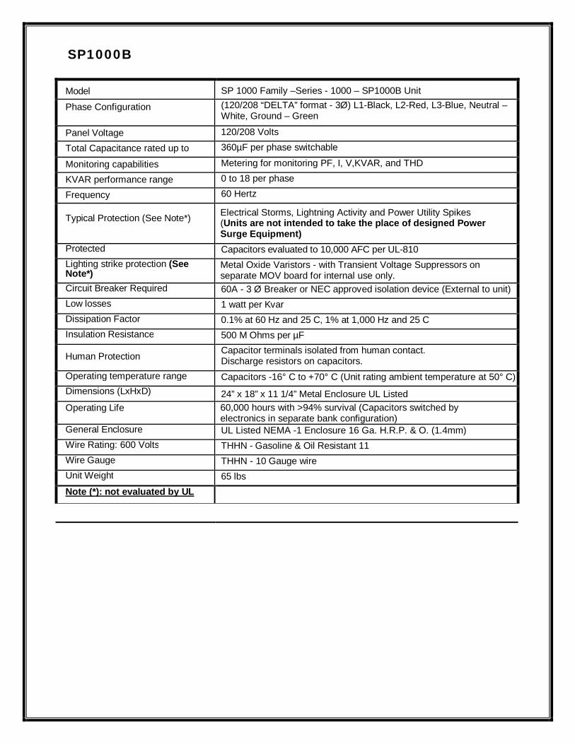
SP1000B
Model SP 1000 Family –Series - 1000 – SP1000B Unit
Phase Configuration (120/208 “DELTA” format - 3Ø) L1-Black, L2-Red, L3-Blue, Neutral – White, Ground – Green
Panel Voltage 120/208 Volts
Total Capacitance rated up to 360µF per phase switchable
Monitoring capabilities Metering for monitoring PF, I, V,KVAR, and THD
KVAR performance range 0 to 18 per phase
Frequency 60 Hertz
Typical Protection (See Note*) Electrical Storms, Lightning Activity and Power Utility Spikes (Units are not intended to take the place of designed Power Surge Equipment)
Protected Capacitors evaluated to 10,000 AFC per UL-810 Lighting strike protection (See Note*)
Metal Oxide Varistors - with Transient Voltage Suppressors on separate MOV board for internal use only.
Circuit Breaker Required 60A - 3 Ø Breaker or NEC approved isolation device (External to unit) Low losses 1 watt per Kvar Dissipation Factor 0.1% at 60 Hz and 25 C, 1% at 1,000 Hz and 25 C Insulation Resistance 500 M Ohms per µF
Human Protection Capacitor terminals isolated from human contact. Discharge resistors on capacitors.
Operating temperature range Capacitors -16° C to +70° C (Unit rating ambient temperature at 50° C) Dimensions (LxHxD) 24” x 18” x 11 1/4” Metal Enclosure UL Listed Operating Life 60,000 hours with >94% survival (Capacitors switched by
electronics in separate bank configuration) General Enclosure UL Listed NEMA -1 Enclosure 16 Ga. H.R.P. & O. (1.4mm) Wire Rating: 600 Volts THHN - Gasoline & Oil Resistant 11 Wire Gauge THHN - 10 Gauge wire Unit Weight 65 lbs Note (*): not evaluated by UL LLC

SP1000B2
Model SP 1000 Family –Series - 1000 – SP1000B2 Unit
Phase Configuration (208 3Ø) L1-Black, L2-Red, L3-Blue, Ground – Green
Panel Voltage 208 Volts
Total Capacitance rated up to 360µF per phase switchable
Monitoring capabilities Metering for monitoring PF, I, V,KVAR, and THD
KVAR performance range 0 to 18 per phase
Frequency 60 Hertz
Typical Protection (See Note*) Electrical Storms, Lightning Activity and Power Utility Spikes (Units are not intended to take the place of designed Power Surge Equipment)
Protected Capacitors evaluated to 10,000 AFC per UL-810 Lighting strike protection (See Note*)
Metal Oxide Varistors - with Transient Voltage Suppressors on separate MOV board for internal use only.
Circuit Breaker Required 60A - 3 Ø Breaker or NEC approved isolation device (External to unit) Low losses 1 watt per Kvar Dissipation Factor 0.1% at 60 Hz and 25 C, 1% at 1,000 Hz and 25 C Insulation Resistance 500 M Ohms per µF
Human Protection Capacitor terminals isolated from human contact. Discharge resistors on capacitors.
Operating temperature range Capacitors -16° C to +70° C (Unit rating ambient temperature at 50° C) Dimensions (LxHxD) 24” x 18” x 11 1/4” Metal Enclosure UL Listed Operating Life 60,000 hours with >94% survival (Capacitors switched by
electronics in separate bank configuration) General Enclosure UL Listed NEMA -1 Enclosure 16 Ga. H.R.P. & O. (1.4mm) Wire Rating: 600 Volts THHN - Gasoline & Oil Resistant 11 Wire Gauge THHN - 10 Gauge wire Unit Weight 65 lbs Note (*): not evaluated by UL LLC

SP1000A
Model SP 1000 Family –Series - 1000 – SP1000A Unit
Phase Configuration (120/208 3Ø “DELTA” format) L1-Black, L2-Red, L3-Blue, Neutral – White, Ground – Green
Panel Voltage 120/208 Volts
Total Capacitance rated up to 180µF per phase switchable
Monitoring capabilities Metering for monitoring PF, I, V,KVAR, and THD
KVAR performance range 0 to 9 per phase
Frequency 60 Hertz
Typical Protection (See Note*) Electrical Storms, Lightning Activity and Power Utility Spikes (Units are not intended to take the place of designed Power Surge Equipment)
Protected Capacitors evaluated to 10,000 AFC per UL-810 Lighting strike protection (See Note*)
Metal Oxide Varistors - with Transient Voltage Suppressors on separate MOV board for internal use only.
Circuit Breaker Required 30A - 3 Ø Breaker or NEC approved isolation device (External to unit) Low losses 1.0 watt per Kvar Dissipation Factor 0.1% at 60 Hz and 25 C, 1% at 1,000 Hz and 25 C Insulation Resistance 500 M Ohms per µF
Human Protection Capacitor terminals isolated from human contact. Discharge resistors on capacitors.
Operating temperature range Capacitors -16° C to +70° C (Unit rating ambient temperature at 50° C) Dimensions (LxHxD) 17” x 12 1/2” x 6 1/2” Metal Enclosure UL Listed
Operating Life 60,000 hours with >94% survival (Capacitors switched by electronics in separate bank configuration)
General Enclosure UL Listed NEMA -1 Enclosure 16 Ga. H.R.P. & O. (1.4mm) Wire Rating: 600 Volts THHN - Gasoline & Oil Resistant 11 Wire Gauge THHN - 10 Gauge wire Unit Weight 23 lbs Note (*): not evaluated by UL LLC

SP1000A2
Model SP 1000 Family –Series - 1000 – SP1000A2 Unit
Phase Configuration (208 3Ø) L1-Black, L2-Red, L3-Blue, Ground – Green
Panel Voltage 208 Volts
Total Capacitance rated up to 180µF per phase switchable
Monitoring capabilities Metering for monitoring PF, I, V,KVAR, and THD
KVAR performance range 0 to 9 per phase
Frequency 60 Hertz
Typical Protection (See Note*) Electrical Storms, Lightning Activity and Power Utility Spikes (Units are not intended to take the place of designed Power Surge Equipment)
Protected Capacitors evaluated to 10,000 AFC per UL-810 Lighting strike protection (See Note*)
Metal Oxide Varistors - with Transient Voltage Suppressors on separate MOV board for internal use only.
Circuit Breaker Required 30A - 3 Ø Breaker or NEC approved isolation device (External to unit) Low losses 1.0 watt per Kvar Dissipation Factor 0.1% at 60 Hz and 25 C, 1% at 1,000 Hz and 25 C Insulation Resistance 500 M Ohms per µF
Human Protection Capacitor terminals isolated from human contact. Discharge resistors on capacitors.
Operating temperature range Capacitors -16° C to +70° C (Unit rating ambient temperature at 50° C) Dimensions (LxHxD) 17” x 12 1/2” x 6 1/2” Metal Enclosure UL Listed Operating Life 60,000 hours with >94% survival (Capacitors switched by
electronics in separate bank configuration) General Enclosure UL Listed NEMA -1 Enclosure 16 Ga. H.R.P. & O. (1.4mm) Wire Rating: 600 Volts THHN - Gasoline & Oil Resistant 11 Wire Gauge THHN - 10 Gauge wire Unit Weight 23 lbs Note (*): not evaluated by UL LLC

SECTION 5 SP1000E/SP1000E2/SP1000E7/SP1000D

SP1000E3/SP1000E8/SP1000D

SP1000B

SP1000B2

SP1000A/SP1000C

SP1000A2

SP1000E/SP1000E2/SP1000E7/SP1000D

SP1000E3/SP1000E8/SP1000D2

SP1000B

SP1000B2

SP1000A/SP1000C

SP1000A2

SP1000E/SP1000E2/SP1000E7/SP1000D

SP1000E3/SP1000E8/SP1000D

SP1000B

SP1000B2

SP1000E/SP1000E2/SP1000E7/SP1000D

SP1000E3/SP1000E8/SP1000D2

SP1000B

SP1000B2

A SP1000 connected at the Load with a Disconnect


SECTION 6 Recommended Parts List
Note: 1. Installation of materials and workmanship at the customer’s sub panel shall be the
responsibility of the qualified Representative in accordance with all state and local codes. Any and all connections exterior to the SP1000 unit shall be the responsibility of the qualified representative.
2. Three Current Transformers External are for connection only to UL Listed energy usage monitoring current transformers.
1. External Current Transformers Split Core (3)supplied by an external source CT302S300 series Current Transformers for use with wire sizes under 350MCM
CT302F300 series Current Transformers for use with wire sizes 350-500MCM
See note #2 Below
2. Transformer wires using 22 AWG stranded (7x30) TC conductors, polypropylene insulation, paper wrap, twisted pair, overall Beldfoil shield (100% coverage), TC drain wire, PVC jacket.
3. One three phase breaker or disconnect switch or Sub Panel rated for the SP1000 model to install. Supplied by qualified representative.
4. One 3/4” UL approved ° watertight connector with seal-tight between sub panel and SP1000 with work box. Supplied by qualified representative.
5. One 1/2 UL approved watertight connector and appropriate junction box with seal-tight between sub panel and SP1000.
6. One 1/2 UL approved watertight connector for Cat 5 cable installation. Supplied by qualified representative.
7. Wire ties or approved straps for installing all transformers. Supplied by qualified representative. 8. Miscellaneous lot materials. Supplied by qualified representative.

SECTION 7

RETURN POLICY
In the event you are not satisfied with a Power Metrics International Inc. (PMI) product, the following applies in determining the return options:
If, at the time of shipment, a product is materially different from that described on a signed proposal or applicable specification sheet referenced thereby, or in the event that the proposed savings (usually estimated at 8%) or software reporting functionally is impaired as described in a specification sheet, and (PMI) is notified of the problem within (90) days of product shipment, (PMI) will:
Replace the product that does not conform to the specification sheet or proposal term or Refund the purchase price of the product that does not conform to the specification sheet or
proposal term.
(PMI) accepts no liability or responsibility for rejected and/or defective products other than the above – mentioned replacement of product or refund of purchase price.
CUSTOM PRODUCTS: CANNOT BE REFUNDED (IN DETERMINING PRODUCT RETURN OPTIONS, ANY PRODUCT THAT IS CUT TO SPECIFIC DIMENSIONS TO SATISFY THE REQUIREMENTS OF AN ORDER IS TO BE CONSIDERED A CUSTOM PRODUCT EVEN IF THE PRODUCT WOULD OTHERWISE QUALIFY AS STANDARD PRODUCT).
Standard products: can be returned to PMI, provided customer is responsible for returning the product, in good, resalable condition, in original packaging to PMI.
Products that have been processed, or altered (during installation or otherwise) in any way cannot be returned and will void the limited warranty.
Products to be returned must be returned using the PMI/RMA (Return Material Authorization from).
(PLEASE FOLLOW ALL INSTRUCTIONS)
POWER METRICS INTERNATIONAL (PMI)
Corporate Headquarters 1961 Richmond Terrace Staten Island, NY 10302 (718) 524-4370
West Coast Operations 9543 Heinrich Hertz Dr. #5
San Diego, CA 92154 (619) 661-0600

WARRANTY
PMI warrants all products sold hereunder to be free from defect in manufacturing, under normal and proper storage, installation and use for the period of three (3) years from the date of shipment. Our guarantee and obligations under this warranty and the sole remedy for its breach are limited to repair at its manufacturing facility of any part or parts of the product which prove to be defective or in the sole discretion of PMI for the replacement of such products. All returns of defective parts and products must include the product model number and serial number and must be arranged through a PMI authorized distributor. All returns must be shipped prepaid. Repaired or replaced parts will or replaced parts will be shipped by PMI fob shipping point. The warranty provided herein does not cover charges for labor, or any other costs incurred in the troubleshooting, repair, removal, installation, service or handling of parts or complete products. PMI shall not be responsible for damages that result from deliveries that do not occur within the customer’s specified time frame or any delay or default in delivering products where occasioned by any cause beyond the control of PMI, including without limitation, embargoes, shortage of labor, raw materials or fuel, fires, floods, accidents, acts of law or similar causes. All claims under this warranty provided herein must be made within 90 days from the date of the discovery of the default. Failure to notify PMI of a warranty defect within 90 days of its discovery voids all obligations hereunder. The warranty provided herein shall be void and of no effect in the event (a) the product has been operated outside its designed output capacity; (b) the product has been subjected to misuse, neglect, accident, improper or inadequate maintenance, corrosive environments containing airborne contaminants (silicone, aluminum oxide, etc.), or excessive thermal shock; (c) unauthorized modifications are made to the product; (d) the product is not installed or operated in compliance with the manufacturer’s printed instructions; (e) the product is not installed and operated in compliance with applicable building, mechanical, plumbing and electrical codes; or (f) the serial number of the product has been altered, defaced or removed. Without limiting the foregoing, purchaser assumes all risk and liability for loss, damage or injury to purchaser, purchaser’s goods and property, and to others and their property, arising out of the use, misuse or inability to use this Unit sold by Manufacturer not caused directly by negligence or Manufacturer. This limited warranty shall not extend to anyone other than the original purchaser of this Unit, is nontransferable and states your exclusive remedy. THIS WARRANTY IS THE SOLE AND EXCLUSIVE WARRANTY FOR PMI PRODUCTS, AND IS IN LIEU OF ALL OTHER EXPRESS AND IMPLIED WARRANTIES. PMI SPECIFICALLY DISCLAIMS ALL OTHER EXPRESS AND IMPLIED WARRANTIES, INCLUDING, BUT NOT LIMITED TO, ALL IMPLIED WARRANTIES OF MERCHANTABILITY AND FITNESS FOR A PARTICULAR PURPOSE. No person or entity is authorized to bind PMI to any other warranty, obligation or liability for any PMI product. Installation, operation or use of PMI product for which this warranty is issued shall constitute acceptance of the terms hereof.
POWER METRICS INTERNATIONAL (PMI)
Corporate Headquarters 1961 Richmond Terrace Staten Island, NY 10302 (718) 524-4370
West Coast Operations 9543 Heinrich Hertz Dr. #5
San Diego, CA 92154 (619) 661-0600