sp1 stereo vision system - nerian vision technologies · sp1 stereo vision system user manual...
TRANSCRIPT

SP1 Stereo Vision SystemUser Manual
(v1.12) February 15, 2017
VISION TECHNOLOGIES
Nerian Vision TechnologiesDr. Konstantin Schauwecker
Gotenstr. 970771 Leinfelden-Echterdingen
Germany
Email: [email protected]://nerian.com
Contents
1 Functionality Overview 3
2 Included Parts 3
3 General Specifications 33.1 Hardware Details . . . . . . . . . . . . . . . . . . . . . . . . . . 33.2 Stereo Matching . . . . . . . . . . . . . . . . . . . . . . . . . . . 43.3 Image Rectification . . . . . . . . . . . . . . . . . . . . . . . . . 43.4 Achievable Frame Rates and Image Resolutions . . . . . . . . . 4
4 Mechanical Specifications 44.1 Dimensions . . . . . . . . . . . . . . . . . . . . . . . . . . . . . 44.2 Mounting . . . . . . . . . . . . . . . . . . . . . . . . . . . . . . 6
5 Physical Interfaces 6
6 Hardware Setup 86.1 Connecting the SP1 . . . . . . . . . . . . . . . . . . . . . . . . . 86.2 Supported Cameras . . . . . . . . . . . . . . . . . . . . . . . . . 8
6.2.1 Recommendation for 640 x 480 Resolution at 30 fps . . . 96.2.2 Recommendation for 800 x 592 Resolution at 20 fps . . . 96.2.3 Recommendation for 1248 x 960 Resolution at 8 fps . . . 106.2.4 Recommendation for 1440 x 1072 Resolution at 6 fps . . 10
6.3 Camera Alignment . . . . . . . . . . . . . . . . . . . . . . . . . 106.4 Other Image Sources . . . . . . . . . . . . . . . . . . . . . . . . 116.5 External Trigger . . . . . . . . . . . . . . . . . . . . . . . . . . . 116.6 Time Synchronization Signal . . . . . . . . . . . . . . . . . . . . 12
7 Processing Results 127.1 Rectified Images . . . . . . . . . . . . . . . . . . . . . . . . . . . 127.2 Disparity Maps . . . . . . . . . . . . . . . . . . . . . . . . . . . 137.3 Timestamps and Sequence Numbers . . . . . . . . . . . . . . . . 15
8 Configuration 158.1 System Status . . . . . . . . . . . . . . . . . . . . . . . . . . . . 168.2 Preview . . . . . . . . . . . . . . . . . . . . . . . . . . . . . . . 178.3 Processing Settings . . . . . . . . . . . . . . . . . . . . . . . . . 18
8.3.1 Operation Mode . . . . . . . . . . . . . . . . . . . . . . 188.3.2 Disparity Settings . . . . . . . . . . . . . . . . . . . . . . 188.3.3 Algorithm Settings . . . . . . . . . . . . . . . . . . . . . 20
8.4 Cameras . . . . . . . . . . . . . . . . . . . . . . . . . . . . . . . 218.4.1 Camera Selection . . . . . . . . . . . . . . . . . . . . . . 218.4.2 Camera Settings . . . . . . . . . . . . . . . . . . . . . . 21
1

8.4.3 Recommended Settings for Karmin 3D Stereo Camera . 228.4.4 Recommended Settings for Point Grey Cameras . . . . . 238.4.5 Recommended Settings for IDS Imaging Cameras . . . . 238.4.6 Recommended Settings for Basler Cameras . . . . . . . . 24
8.5 Trigger / Pairing . . . . . . . . . . . . . . . . . . . . . . . . . . 248.6 Time Synchronization . . . . . . . . . . . . . . . . . . . . . . . 258.7 Camera Calibration . . . . . . . . . . . . . . . . . . . . . . . . . 26
8.7.1 Calibration Board . . . . . . . . . . . . . . . . . . . . . . 268.7.2 Recording Calibration Frames . . . . . . . . . . . . . . . 288.7.3 Performing Calibration . . . . . . . . . . . . . . . . . . . 28
8.8 Reviewing Calibration Results . . . . . . . . . . . . . . . . . . . 298.9 Auto Re-calibration . . . . . . . . . . . . . . . . . . . . . . . . . 328.10 Network Settings . . . . . . . . . . . . . . . . . . . . . . . . . . 338.11 Maintenance . . . . . . . . . . . . . . . . . . . . . . . . . . . . . 34
9 API Usage Information 359.1 General Information . . . . . . . . . . . . . . . . . . . . . . . . 359.2 ImageTransfer Example . . . . . . . . . . . . . . . . . . . . . . 369.3 AsyncTransfer Example . . . . . . . . . . . . . . . . . . . . . . 379.4 3D Reconstruction . . . . . . . . . . . . . . . . . . . . . . . . . 38
10 Supplied Software 3810.1 SpCom . . . . . . . . . . . . . . . . . . . . . . . . . . . . . . . . 3810.2 GenICam GenTL Producer . . . . . . . . . . . . . . . . . . . . 40
10.2.1 Installation . . . . . . . . . . . . . . . . . . . . . . . . . 4010.2.2 Virtual Devices . . . . . . . . . . . . . . . . . . . . . . . 4110.2.3 Device IDs . . . . . . . . . . . . . . . . . . . . . . . . . . 4210.2.4 Device Enumeration . . . . . . . . . . . . . . . . . . . . 42
10.3 ROS Node . . . . . . . . . . . . . . . . . . . . . . . . . . . . . . 43
11 Support 43
12 Warranty Information 43
13 Open Source Information 44
2

3 GENERAL SPECIFICATIONS
1 Functionality OverviewThe SP1 stereo vision system is a stand-alone processing system for performingstereo matching in real time. It connects to two industrial USB cameras thatprovide input image data. The SP1 correlates the images of both camerasand produces a disparity map, which is transmitted through gigabit ethernet.The disparity map describes a mapping of image points from the left cameraimage to corresponding image points in the right camera image. With thisinformation it is possible to reconstruct the 3D location of the correspondingscene points.
2 Included PartsWhen ordering a new SP1 from Nerian Vision Technologies, the package shouldinclude the following items:
• SP1 stereo vision system
• 5 V DC power adapter
• 4 stickable rubber pads
• Mounting plate
• 4 mounting screws
• Manual
If any of the listed items is missing in your delivery, then please contact us.
3 General Specifications
3.1 Hardware Details
Power consumption < 4 WPower supply 5 V DCDimensions 105 x 76 x 36 mmWeight 0.25 kgI/O USB 2.0 host, Gigabit Ethernet, 2x trigger out,
synchronization input (pin shared with trigger 1)Max. USB power 500 mA
3
3.2 Stereo Matching 4 MECHANICAL SPECIFICATIONS
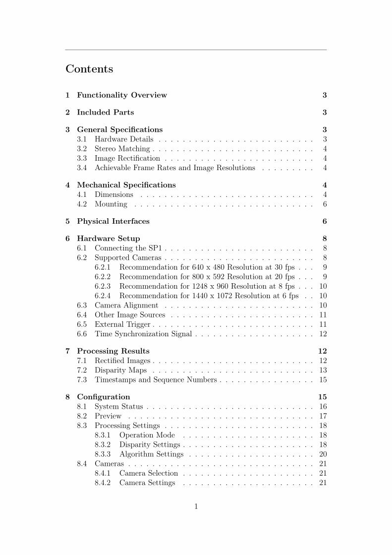
Table 1: Possible frame rate by image resolution and disparity range.
Image Resolution640 × 480 800 × 592 1248 × 960 1440 × 1072
Disp.
Ran
ge 64 40 fps 25 fps 9 fps 7 fps128 30 fps 20 fps 8 fps 6 fps256 15 fps 10 fps 4 fps n/a
3.2 Stereo Matching
Stereo algorithm Semi-Global Matching (SGM)Image resolution Configurable from 320×240 pixels up to 1440×
1440 pixels1Disparity range Configurable from 32 to 256 pixelsFrame rate Up to 40 fps depending on image size and dis-
parity rangeSub-pixel resolution 4 bits (1/16 pixel)Post-processing Consisteny check, uniqueness check, gap inter-
polation, noise reduction, speckle filtering
3.3 Image Rectification
Horizontal displacement −39 to +39 pixelsVertical displacement −39 to +39 pixelsInterpolation Bilinear
3.4 Achievable Frame Rates and Image Resolutions
The frame rates that can be achieved depends on the image size and the con-figured disparity range. Table 1 provides a list of recommended configurations.Other configurations are also possible.
4 Mechanical Specifications
4.1 Dimensions
Figures 1a to 1d show the SP1 as seen from front, rear, side and top. Theprovided dimensions are measured in millimeters.
1When using a disparity range of 128 pixels. A larger disparity range might might leadto a smaller maximum image resolution.
4

4.1 Dimensions 4 MECHANICAL SPECIFICATIONS
-75
?
6
36
(a)
-75
?
6
36
(b)
-105
?
6
36
(c)
-105
?
6
75
(d)
Figure 1: (a) Front, (b) rear, (c) side and (d) top view of SP1 with dimensionsin millimeters.
5

4.2 Mounting 5 PHYSICAL INTERFACES
Figure 2: SP1 with attached mounting plate.
4.2 Mounting
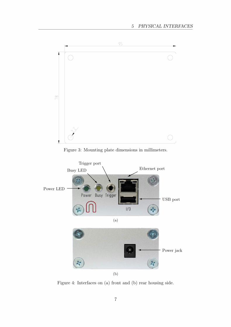
For mounting the SP1 please use the included mounting plate. The mountingplate is attached to the bottom of the SP1 with the four included mountingscrews. The four through holes at the corners of the plate allow the SP1 to befixed onto a flat surface. The through holes are compatible to screws with anM4 ISO metric thread.
An image of the SP1 with attached mounting plate is shown in Figure 2.The dimensions of the mounting plate are shown in millimeters in Figure 3.Please only use the provided screws for attaching the plate or any other objectto the SP1. Using screws with a higher length might damage theinside electronics.
5 Physical InterfacesFigures 4a and 4b show the interfaces on the SP1’s front and backside. Thepower jack is located on the backside, and it needs to be connected to thesupplied power adapter or an equivalent model. When using an alternativepower supply, please make sure that the voltage is set to 5 V DC. Highervoltages might damage the device.
The front side features the following interfaces:
Power LED: Indicates that the device is powered up and running.
Busy LED: Indicates that the device is currently processing image data.
Trigger port: Port for providing two camera trigger signals. It is possibleto disable one trigger signal and use the dedicated pin as input for asynchronization signal. Please see Sections 6.5 and 6.6.
6
5 PHYSICAL INTERFACES
Figure 3: Mounting plate dimensions in millimeters.
-Power LED
@@@R
Busy LED AAAAAU
Trigger port
Ethernet port
USB port
(a)
Power jack
(b)
Figure 4: Interfaces on (a) front and (b) rear housing side.
7

6 HARDWARE SETUP
USB camerasComputer
SP1
USB hub
EthernetSynchronization cable
Figure 5: Example setup for cameras, SP1 and client computer.
Ethernet port: Port for connecting to a client computer. It is used for de-livering processing results and for providing access to the configurationinterface.
USB port: Port for connecting the desired USB cameras through a USB hub.
6 Hardware Setup
6.1 Connecting the SP1
Figure 5 shows a basic system setup for stereo vision. A client computerthat receives the processing results is connected to the SP1’s ethernet port.Alternatively it is possible to connect the SP1 to a switched network. However,you have to ensure that the network is capable of handling the high bandwidthdata that is transmitted by the device. The network must support data ratesof at least 25 MB/s without packet drops.
The cameras are connected to the SP1’s USB port. As the SP1 only featuresone USB port, a USB hub is mandatory for making this connection. Pleasenote that the USB hub usually has to be powered externally, in orderto meet the power consumption of the cameras.
The image acquisition of both cameras has to be synchronized. The SP1will only process frames with a matching time stamp. Operating the cam-eras in free-run mode will thus result in dropped frames. Dependingon your configuration, synchronization might require connecting the camerasto the SP1’s trigger port (see Section 6.5).
6.2 Supported Cameras
In addition to our own stereo camera Karmin, the SP1 also supports a varietyof greyscale cameras from Point Grey Research Inc., IDS Imaging Development
8

6.2 Supported Cameras 6 HARDWARE SETUP
Systems GmbH and Basler AG. Below you find a list of all camera models thatare known to be compatible, sorted by the recommended resolution.
6.2.1 Recommendation for 640 x 480 Resolution at 30 fps
• Karmin 3D Stereo Camera
• Point Grey Blackfly:BFLY-U3-03S2M-CS, BFLY-U3-13S2M-CS
• Point Grey Chameleon3:CM3-U3-13S2M-CS, CM3-U3-13Y3M-CS
• Point Grey Flea3:FL3-U3-13E4M-C, FL3-U3-13Y3M-C
• Point Grey Grasshopper3:GS3-U3-14S5M-C, GS3-U3-15S5M-C
• Basler dart:daA1600-54um
• IDS uEye ML:UI-3240ML-M-GL
• IDS uEye CP:UI-3240CP-M-GL Rev.2
6.2.2 Recommendation for 800 x 592 Resolution at 20 fps
• Karmin 3D Stereo Camera
• Point Grey Blackfly:BFLY-U3-05S2M-CSBFLY-U3-23S6M-C
• Point Grey Flea3:FL3-U3-20E4M-C
• Point Grey Grasshopper3:GS3-U3-23S6M-C
• Basler dart:daA1600-60um
• IDS uEye ML:UI-3250ML-M-GL
• IDS uEye CP:UI-3250CP-M-GL Rev.2
9

6.3 Camera Alignment 6 HARDWARE SETUP
Figure 6: Example for standard epipolar geometry.
6.2.3 Recommendation for 1248 x 960 Resolution at 8 fps
• Point Grey Blackfly:BFLY-U3-03S2M-CS, BFLY-U3-13S2M-CS
• Point Grey Chameleon3:CM3-U3-13S2M-CS, CM3-U3-13Y3M-CS
• Point Grey Flea3:FL3-U3-13E4M-C, FL3-U3-13Y3M-C
• Point Grey Grasshopper3:GS3-U3-14S5M-C, GS3-U3-15S5M-C
6.2.4 Recommendation for 1440 x 1072 Resolution at 6 fps
• Point Grey Blackfly:BFLY-U3-05S2M-CSBFLY-U3-23S6M-C
• Point Grey Flea3:FL3-U3-20E4M-C
• Point Grey Grasshopper3:GS3-U3-23S6M-C
Other models of the given camera lines might also be compatible. Pleasecontact us if you require assistance with camera selection.
6.3 Camera Alignment
Both cameras have to be mounted on a plane with a displacement that isperpendicular to the cameras’ optical axes. Furthermore, both cameras mustbe equipped with lenses that have an identical focal length. This arrangementis known as the standard epipolar geometry. An example for such a cameramounting is shown in Figure 6.
The distance between both cameras is referred to as baseline distance. Us-ing a large baseline distance improves the depth resolution at high distances.
10

6.4 Other Image Sources 6 HARDWARE SETUP
A small baseline distances, on the other hand, allows for the observation ofclose objects. The baseline distance should be adjusted in conjunction withthe lenses’ focal length. An online tool for computing desirable combinationsof baseline distance and focal length can be found on the Nerian Vision Tech-nologies website2.
6.4 Other Image Sources
The SP1 can alternatively process image data that does not originate fromreal cameras. To allow for an easy evaluation, each SP1 ships with an examplestereo sequence on its internal memory. This example sequence appears astwo virtual cameras that can be selected during camera configuration (seeSection 8.4). If selected, the example sequence is replayed in an infinite loop.Due to speed limitations of the internal memory, the example sequence is notreplayed at the full frame rate during the first loop iteration.
Another set of virtual cameras provide the ability to receive image data overthe ethernet port. In this case a computer has to transmit a set of image pairsto the SP1, and it then receives the processing results over the same network.Please note that this significantly increases the required network bandwidth.The bandwidth usage can be reduced by transferring image data at a lowerframe rate. It is highly recommended to always use TCP as underlying networkprotocol when performing network image transfer, in order to avoid droppedframes.
The SpCom application that is described in Section 10.1 can be used fortransferring a set of locally stored images to the SP1. This can be achievedby pressing the appropriate button in the toolbar, and selecting a directorywith a collection of image files. The image files in this directory are thentransmitted in alphabetical order. Please make sure that image files for theleft camera always appear before their right camera counter parts when sortedalphabetically.
6.5 External Trigger
For stereo matching it is important that both cameras are synchronized, mean-ing that both cameras record an image at exactly the same point of time. Manyindustrial cameras already feature the ability to synchronize themselves, byhaving one camera produce a trigger signal for the respective other camera.
As an alternative, the SP1 can produce up to two trigger signals. Thesignals are provided through the trigger port, which can receive a standard3.5 mm phone connector. The pin assignment for this connector is shown inFigure 7.
The peak voltage of both trigger signals is at +3.3 V. The polarity of thetrigger signals is active high. For exact timing measurements it is recom-
2http://nerian.com/support/resources/calculator/
11

6.6 Time Synchronization Signal 7 PROCESSING RESULTS
Ground
Trigger 0
Trigger 1 /Sync.
Figure 7: Pin assignement for trigger output.
mended that the cameras trigger on the rising signal edge. The pulse widthand frequency can be adjusted in the trigger configuration (see Section 8.5).To protect the trigger port from short circuits, each signal line is connectedthrough a resistor. For models shipped before October 2016, a resistor of 220Ω is connected in series. For later models, a resistor of 68 Ω is used.
6.6 Time Synchronization Signal
As indicated in Figure 7, the pin dedicated to trigger signal 1 can alternativelybe configured as input for a time synchronization signal (see Section 8.6). Inthis case, the internal clock is set to 0 whenever a rising signal edge is received.The signal must have a voltage level of +3.3 V. Please avoid higher voltagesas they might damage the device.
Clock synchronization is useful when interpreting the timestamps that areembedded in the transmitted processing results (see Section 7.3). The syn-chronization input can be connected to the pulse-per-second (PPS) output ofa GPS receiver or a precision oscillator, in which case the clock is reset onceper second. This allows for the reconstruction of high-precision timestamps onthe computer receiving the SP1’s processing results.
As an alternative to synchronizing to an external signal, the SP1 can alsoperform a clock synchronization through the Network Time Protocol (NTP),as described in Section 8.6.
7 Processing Results
7.1 Rectified Images
Even when carefully aligning both cameras, you are unlikely to receive imagesthat match the expected result form an ideal standard epipolar geometry. Theimages are affected by various distortions that result from errors in the cameras’
12

7.2 Disparity Maps 7 PROCESSING RESULTS
(a) (b)
Figure 8: Example for (a) unrectified and (b) rectified camera image.
optics and mounting. Therefore, the first processing step that is performed isan image undistortion operation, which is known as image rectification.
Image rectification requires precise knowledge of the cameras’ projectiveparameters. These can be determined through camera calibration. Please referto Section 8.7 for a detailed explanation of the camera calibration procedure.
Figure 8a shows an example camera image, where the camera was pointedtowards a calibration board. The edges of the board appear slightly bent, dueto radial distortions caused by the camera’s optics. Figure 8b shows the sameimage after image rectification. This time, all edges of the calibration boardare perfectly straight.
When performing stereo matching, the SP1 additionally outputs the rec-tified left camera image. This allows for a mapping of features in the visibleimage to structures in the determined scene depth and vice versa.
7.2 Disparity Maps
The stereo matching results are delivered in the form of a disparity map fromthe perspective of the left camera. The disparity map associates each pixelin the left camera image to a corresponding pixel in the right camera image.Because both images were previously rectified to match an ideal standardepipolar geometry, corresponding pixels should only differ in their horizontalcoordinates. The disparity map thus only encodes a horizontal coordinatedifference.
An example for a left camera image and the corresponding disparity mapare shown in Figures 9a and 9b. Here the disparity map has been color coded,with blue hues reflecting small disparities, and red hues reflecting large dispar-ities. As can be seen, the disparity is proportional to the inverse depth of thecorresponding scene point.
The disparity range specifies the image region that is searched for findingpixel correspondences. In the example image, the color legend indicates that
13

7.2 Disparity Maps 7 PROCESSING RESULTS
(a) (b)
Figure 9: Example for (a) left camera image and corresponding disparity map.
the disparity range reaches from 0 to 111 pixels. A large disparity range allowsfor very accurate measurements, but causes a high computational load and thuslowers the achievable frame rate. The SP1 supports a configurable disparityrange (see Section 8.3), which allows the user to choose between high precisionor high speed.
It is possible to transform the disparity map into a set of 3D points. Thiscan be done at a correct metric scale if the cameras have been calibrated prop-erly. The transformation of a disparity map into a set of 3D points requiresknowledge of the disparity-to-depth mapping matrix Q, which is computedduring camera calibration and transmitted by the SP1 along with each dispar-ity map. The 3D location
(x y z
)T of a point with image coordinates (u, v)and disparity d can be reconstructed as follows:
xyz
=1
w·
x′
y′
z′
, with
x′
y′
z′
w
= Q ·
uvd1
When using the provided Q matrix, the received coordinates will be mea-
sured in meters with respect to the coordinate system depicted in Figure 10.Here, the origin matches the left camera’s center of projection. An efficientimplementation of this transformation is provided with the available API (seeSection 9.4).
The SP1 computes disparity maps with a disparity resolution that is belowone pixel. Disparity maps have a bit-depth of 12 bits, with the lower 4 bits ofeach value representing the fractional disparity component. It is thus necessaryto divide each value in the disparity map by 16 in order to receive the correctdisparity magnitude.
The SP1 applies several post-processing techniques in order to improvethe quality of the disparity maps. Some of these methods detect erroneousdisparities and mark them as invalid. Invalid disparities are set to 0xFFF,
14

7.3 Timestamps and Sequence Numbers 8 CONFIGURATION
xz (optical axis)
y
Camera
Figure 10: Coordinate system used for 3D reconstruction.
which is the highest value that can be stored in a 12-bit disparity map. InFigure 9b invalid disparities have been depicted as black.
7.3 Timestamps and Sequence Numbers
Each pair of rectified left camera image and disparity map, which is transmittedby the SP1, also includes a timestamp and a sequence number. The timestampis measured with microsecond accuracy and is set to either the time at which acamera trigger signal was generated or the time at which a frame was receivedfrom the cameras (see Section 8.5). For images that are received over thenetwork, as described in Section 6.4, the timestamp and the sequence numberare both copied.
As explained in Sections 6.6 and 8.6, it is possible to synchronize the SP1’sinternal clock to an external signal or a time server. This directly affects theproduced time stamps. When synchronized to a time server, time stamps aremeasured in microseconds since 1 January 1970, 00:00:00 UTC. If no synchro-nization is performed, the internal clock is set to 0 at the time the SP1 ispowered up. If synchronizing to an external signal, the clock is set to 0 at therising edge of the synchronization signal.
Please note that synchronizing to a PPS signal, as explained in Section 6.6,also produces negative timestamps. Depending on the selected timestampsource, this happens when a synchronization signal is received while the SP1is processing an already captured image pair, or while the SP1 is waiting fora frame corresponding to an already generated trigger signal. The negativetimestamp is then the time difference between the reception of the synchro-nization signal and the time of capturing or triggering the current image pair.
8 ConfigurationThe SP1 is configured through a web interface, which can be reached by en-tering the IP address of the SP1 in your browser. The default address ishttp://192.168.10.10. Please configure the IP address and subnet mask of your
15

8.1 System Status 8 CONFIGURATION
Figure 11: Screenshot of configuration status page.
computer appropriately, such that this interface can be reached. If the SP1has just been plugged in, it will take several seconds before the web interfaceis accessible.
For using the web interface you require a browser with supportfor HTML 5. Please use a recent version of one of the major browsers, suchas Internet Explorer, Firefox, Chrome or Safari.
8.1 System Status
The first page that you see when opening the web interface is the system statuspage that is shown in Figure 11. On this page you can find the followinginformation:
Processing status: Indicates whether the image processing sub-system hasbeen started. If this is not the case then there might be a problemaccessing the cameras, or another system error might have occurred.Please consult the system logs in this case. The image processing sub-system will be started immediately once the cause of error has beenremoved (such as connecting the cameras).
SOC temperature: The temperature of the central System-on-Chip (SoC)that performs all processing tasks. The maximum operating temperaturefor the employed SoC is at 85 C. A green-orange-red color-coding isapplied to signal good, alarming and critical temperatures.
16

8.2 Preview 8 CONFIGURATION
Figure 12: Screenshot of configuration preview page.
System logs: List of system log messages sorted by time. In regular operationyou will find information on the current system performance. In case oferrors, the system logs contain corresponding error messages.
8.2 Preview
The preview page, which is shown in Figure 12, provides a live preview of thecurrently computed disparity map. Please make sure that your network con-nection supports the high bandwidth that is required for streaming video data(see Section 6.1). For using the preview page you require a direct connectionto the SP1. An in-between proxy server or a router that performs networkaddress translation (NAT) cannot be used.
When opening the preview page, the SP1 stops transferring image data toany other host. The transfer is continued as soon as the browser window isclosed, the user presses the pause button below the preview area, or if the usernavigates to a different page. Only one open instance of the preview page,or any other page that is streaming video data to the browser, is allowed ata time. If attempted to open more than once, only one instance will receivedata.
The preview that is displayed in the browser does not reflect the full qual-
17

8.3 Processing Settings 8 CONFIGURATION
ity of the computed disparity map. In particular, sub-pixel accuracy is notavailable, and your browser might not be able to display the disparity map atthe full camera frame rate. To receive a full-quality preview, please use theSpCom application, which is described in Section 10.1.
Different color-coding schemes can be selected through the drop-down listbelow the preview area. A color scale is shown to the right, which providesinformation on the mapping between colors and disparity values. The possiblecolor schemes are:
Red / blue: A gradient from red to blue, with red hues corresponding tohigh disparities and blue hues corresponding to low disparities. Invaliddisparities are depicted in black.
Rainbow: A rainbow color scheme with low wavelengths corresponding tohigh disparities and high wavelengths corresponding to low disparities.Invalid disparities are depicted in grey.
Raw data: The raw disparity data without color-coding. The pixel inten-sity matches the integer component of the measured disparity. Invaliddisparities are displayed in light gray.
8.3 Processing Settings
8.3.1 Operation Mode
The major processing parameters can be changed on the processing settingspage, which is shown in Figure 13. The most relevant option is the operationmode, which can be set to one of the following values:
Pass through: In this mode the SP1 forwards the imagery of the selectedcameras without modification. This mode is intended for verifying thatboth cameras are functioning correctly.
Rectify: In this mode the SP1 transmits the rectified images of both cameras.This mode is intended for verifying the correctness of image rectification.
Stereo matching: In this mode the SP1 performs stereo matching. It trans-mits the rectified image of the left camera and the left camera disparitymap.
8.3.2 Disparity Settings
If the operation mode is set to stereo matching, then the disparity settingsallow for a configuration of the disparity range that is searched by the SP1.The disparity range affects the frame rate that can be achieved. The frame rateshould be adjusted once the disparity range has been changed (see Section 3.4
18

8.3 Processing Settings 8 CONFIGURATION
Figure 13: Screenshot of configuration page for processing settings.
19

8.3 Processing Settings 8 CONFIGURATION
for recommendations). Please be aware that increasing the disparity range willalso reduce the maximum image size that can be configured.
The number of disparities option specifies the total number of pixels thatare searched for correspondences. This option has a high impact on the depthresolution and the covered measurement range (see Section 7.2). The start ofthe disparity range can be chosen through the disparity offset option. Typicallya value of 0 is desired for the offset, which allows for range measurements upto infinity. If the observable distance is certain to be constrained then lowdisparity values will be impossible. In this case it is possible to increase thedisparity offset such that these low disparities are not computed.
8.3.3 Algorithm Settings
The behavior of the image processing algorithms can be controlled throughthe algorithm settings. These settings include the following stereo matchingparameters:
Penalty for disparity changes (P1): A penalty that is applied to gradu-ally changing disparities. A large value causes gradual disparity changesto occur less frequently, while a small value causes gradual changes tooccur more frequently. This value has to be smaller than P2.
Penalty for disparity discontinuities (P2): A penalty that is applied toabruptly changing disparities. A large value causes disparity discontinu-ities to occur less frequently, while a small value causes discontinuitiesto occur more frequently. This value has to be greater than P1.
The SP1 implements several methods for post-processing the computeddisparity map. Each post-processing method can be activated or deactivatedindividually. The available methods are:
Mask border pixels: If enabled, this option marks all disparities that areclose to the border of the visible image area as invalid, as they have ahigh uncertanty. This also includes all pixels for which no actual imagedata is available due to the image rectification (see Section 7.1).
Consistency check: If enabled, stereo matching is performed in both match-ing directions, left-to-right and right-to-left. Pixels for which the dispar-ity is not consistent are marked as invalid. The sensitivity of the consis-tency check can be controlled through the consistency check sensitivityslider.
Uniqueness check: If enabled, pixels in the disparity map are marked asinvalid if there is no sufficiently unique solution (i.e. the cost functiondoes not have a global minimum that is significantly lower than all otherlocal minima). The sensitivity of the uniqueness check can be controlledthrough the uniqueness check sensitivity slider.
20
8.4 Cameras 8 CONFIGURATION
Texture filter: If enabled, pixels that belong to image regions with littletexture are marked as invalid in the disparity map, as there is a highlikelihood that these pixels have been mismatched. The sensitivity ofthis filter can be adjusted through the texture filter sensitivity slider.
Gap interpolation: If enabled, small patches of invalid disparities, which arecaused by by one of the preceding filters, are filled through interpolation.
Noise reduction: If enabled, an image filter is applied to the disparity map,which reduces noise and removes outliers.
Speckle filter: Marks small isolated patches of similar disparity as invalid.Such speckles are often the result of erroneous matches.
8.4 Cameras
8.4.1 Camera Selection
The cameras page that is shown in Figure 14 allows for the selection of adesired camera pair and the adjustment of their respective parameters. Alldetected cameras are listed in the camera selection list. A source is listed foreach camera, which identifies the utilized camera driver. The cameras list alsoincludes the two virtual camera pairs that are mentioned in Section 6.4, whichprovide an example stereo sequence or facilitate the reception of input imagesthrough ethernet.
To choose a particular camera, you have to tick either the use as left or useas right radio button, for selecting the camera as the left or right camera ofthe stereo pair. Please note that cameras of different sources cannot be usedtogether.
8.4.2 Camera Settings
After selecting a camera pair, camera specific settings can be adjusted in theleft camera settings and right camera settings area. The available settingsdepend on your camera model. Please refer to your camera documentation fordetails.
More advanced camera settings are hidden by default and can be displayedby clicking the show advanced settings link. Some particular settings of yourcameras might not be available. In this case please use the software providedby the camera manufacturer to adjust the desired settings and safe the newcamera configuration to the cameras’ internal memory.
By pressing the reset camera defaults button you can reset the cameras’settings to the default configuration. This is usually the configuration thathas been written to the cameras’ internal memory through the manufacturersoftware. If the reset button is pressed, all configuration changes that have notbeen confirmed through the change button are reverted.
21

8.4 Cameras 8 CONFIGURATION
Figure 14: Screenshot of configuration page for camera settings.
For all cameras it is possible to configure the size of the processed RegionOf Interest (ROI). The smaller the ROI the higher is the frame rate that can beachieved. Recommended ROI and frame rate settings are listed in Section 3.2on page 4. When choosing a custom image size, please adjust the frame ratesuch that a stable processing rate is achieved.
The SP1 offers the functionality to synchronize parameters that are other-wise automatically adjusted by each camera. For example, each camera mightcontrol its shutter time through an auto shutter algorithm. The SP1 can syn-chronize such auto-adjusted parameters by setting the parameters of the rightcamera to always match the respective parameters of the left camera.
If this functionality is desired, the mode for the particular feature has tobe set to synchronize to left camera in the right camera settings, and to autoin the left camera settings. In this case, the SP1 will query the settings of theleft camera and adjust the right camera’s settings accordingly.
8.4.3 Recommended Settings for Karmin 3D Stereo Camera
The Karmin 3D Stereo Camera by Nerian Vision Technologies is automaticallyconfigured with the recommended settings when being plugged in. However,the trigger settings need to be configured manually according to your triggersource. When connecting the camera to the SP1’s trigger port, please selectline 1 as trigger source for trigger signal 0, and line 2 as source for triggersignal 1. The trigger polarity is rising edge.
22
8.4 Cameras 8 CONFIGURATION
8.4.4 Recommended Settings for Point Grey Cameras
When using Point Grey USB cameras we recommend that you use the followingsettings:
• Enable external trigger and select the desired trigger source.
• If the cameras are connected to the SP1’s trigger port, set the triggerpolarity to active high. Otherwise set the polarity according to yourtrigger source.
• Set the trigger mode to 14 (recommended) or 0. Always use mode 14 ifthe internal camera frame rate is not significantly higher than the triggerfrequency.
• If an automatic adjustment of exposure, sharpness and shutter is desired,then please apply the following settings:
– For the left camera, set the mode of exposure, sharpness, shutterand gain to auto.
– For the right camera, set the mode of exposure, sharpness, shutterand gain to synchronize to left camera.
8.4.5 Recommended Settings for IDS Imaging Cameras
When using cameras from IDS Imaging, we recommend that you use the fol-lowing settings:
• If the cameras shall be triggered by the SP1 trigger output:
– Due to voltage levels, the SP1 trigger output needs to be connectedto a camera GPIO pin, rather than the trigger input.
– The connected GPIO pin needs to be selected as trigger source.
– The trigger mode shall be set to hardware trigger, rising edge.
• If the cameras shall be triggered by a source other than the SP1, thenplease configure the trigger settings appropriately.
• Set the pixel clock to maximum.
• Set the camera frame rate to at least twice the trigger frequency (theallowed framerate range is influenced by the configured pixel clock).
• If an automatic adjustment of gain, exposure / shutter and black levelis desired, then please apply the following settings:
– For the left camera set the mode of gain, exposure / shutter andblack level to auto.
23

8.5 Trigger / Pairing 8 CONFIGURATION
– For the right camera set the mode of gain, exposure / shutter andblack level to synchronize to left camera.
– Leave auto skip frames at 4 (the default) in order to minimizedropped frames during adjustments.
8.4.6 Recommended Settings for Basler Cameras
• Enable trigger and select the desired trigger source.
• If the trigger signal is provided by the SP1, select rising edge as triggeractivation.
• If an automatic adjustment of exposure and gain is desired, then pleaseapply the following settings:
– For the left camera set auto exposure and auto gain to continuous.
– For the right camera set auto exposure and auto gain to synchronizeto left camera.
– For the left camera reduce the auto exposure upper limit such thatthe frame rate will not drop when the maximum exposure is reached.In our experience, a value of 11,500 us is sufficient for 30 fps, and avalue of 19,000 us is sufficient for operating at 20 fps.
8.5 Trigger / Pairing
The trigger / pairing page that is shown in Figure 15 allows for a configurationof the trigger output and frame pairing settings. Frame pairing refers to theprocess of identifying which left and right camera frames were recorded at thesame time. You can specify a maximum time difference that is allowed for thispairing process. Only frames whose time stamps do not differ by more thanthis maximum difference can form an image pair.
If the cameras provide high resolution images or if they have a low pixeltransfer speed, it is recommended to increase the maximum time difference.As a general guideline, we recommend setting half of the time delay betweentwo frames as the maximum time difference.
The configuration page also allows for a configuration of the SP1’s triggerport. As described in Section 6.5, the SP1 features a trigger port that providesaccess to up to two trigger signals. The two trigger signals, trigger 0 andtrigger 1, can be enabled or disabled by selecting the respective check boxes.
For trigger 0 it is possible to select a frequency between 0.1 and 50 Hz andan arbitrary pulse width in milliseconds. The polarity of the generated triggersignal is active high. If the checkbox ‘use trigger time as timestamp’ is selected,then the trigger time is transmitted as timestamp with each processing result.Please make sure that the cameras do not skip any trigger signals, as in this
24

8.6 Time Synchronization 8 CONFIGURATION
Figure 15: Screenshot of configuration page for trigger settings.
case the timestamp correlation will fail. This functionality should not be usedwith virtual cameras such as the hard-coded example and network capturing.
The signal trigger 1 can only be enabled if trigger 0 is also enabled. Thefrequency is forced to the same value as trigger 0. However, it is possible tospecify a time offset, which is the delay from a rising edge of trigger 0 to arising edge of trigger 1. Furthermore, trigger 1 can have a pulse width thatdiffers from trigger 0. If PPS synchronization is enabled, trigger 1 cannot beused.
8.6 Time Synchronization
The time synchronization page, which is shown in Figure 16, can be used toconfigure two possible methods for synchronizing the SP1’s internal clock. Asexplained in Section 7.3, the internal clock is used for timestamping capturedcamera frames.
The first possible option is to synchronize with a time server, using theNetwork Time Protocol (NTP) up to version 4. In this case the SP1 synchro-nizes its internal clock to the given time server, using Coordinated UniversalTime (UTC). The accuracy of the time synchronization depends on the la-tency of your network and time server. If NTP time synchronization is active,synchronization statistics are displayed in a dedicated status area.
When activating Pulse Per Second (PPS) synchronization, the internalclock is set to 0 whenever a synchronization signal is received, as explained
25

8.7 Camera Calibration 8 CONFIGURATION
Figure 16: Screenshot of configuration page for time synchronization.
in Section 6.6. Please note that PPS synchronization and the trigger 1 outputcannot be active at the same time, as they both use the same physical pin.
8.7 Camera Calibration
8.7.1 Calibration Board
The calibrate cameras page, which is shown in Figure 17, enables the calibrationof the stereo camera pair. You require a calibration board, which is a flat panelwith a visible calibration pattern on one side. The pattern that is used by theSP1 consists of an asymmetric grid of black circles on a white background, asshown in Figure 18.
The pattern can be downloaded directly from the calibration page. Simplyselect the desired paper size in the calibration board drop-down list, and clickthe download link. Even if you already have a calibration board, make sureto always select the correct board size before starting the calibration process.Otherwise the calibration results cannot be used for 3D reconstruction with acorrect metric scale (see Section 7.2).
Should you require a calibration board with a custom size, then you canselect custom from the calibration board drop-down list. This allows you toenter the calibration board details manually. The first dimension of the patternsize is the number of circles in one grid column. This number must be equalfor all columns of the circles grid.
26

8.7 Camera Calibration 8 CONFIGURATION
Figure 17: Screenshot of configuration page for camera calibration.
Size: 4 x 11; Circle spacing: 2.0 cm; Circle diameter: 1.5 cm;
5 cm
2 in
nerian.com
Figure 18: Calibration board used by SP1.
27

8.7 Camera Calibration 8 CONFIGURATION
The number of circles per row is allowed to vary by 1 between odd andeven rows. The second dimension is thus the sum of circles in two consecutiverows. All downloadable default calibration patterns have a size of 4 × 11.
The final parameter that you have to enter when using a custom calibrationboard is the circle spacing. This is the distance between the centers of twoneighboring circles. The distance must be equal in horizontal and verticaldirection for all circles.
8.7.2 Recording Calibration Frames
Once the calibration board settings have been set, you can begin recordingcalibration frames. A live preview of both cameras is displayed in the camerapreview area. Make sure that the calibration board is fully visible in bothcamera images and then press the capture single frame button in the controlsection. Repeat this process several times while moving either the camera orthe calibration board.
The calibration board must be recorded at several different positions andorientations. You should also vary the distance of the board to the cameras andmake sure that you cover most of the cameras’ field of view. When recordingthe calibration frames it is important that both cameras are synchronized.
The more frames you record, the more accurate the computed calibrationwill be. However, more frames also cause the computation of the calibrationparameters to take longer. The SP1 supports the recording of up to 40 cali-bration frames. We recommend to use at least 20 calibration frames in orderto receive accurate results.
The recording of calibration frames can be simplified by activating the autocapture mode. In this mode, a new calibration frame is recorded in fix captureintervals. You can enter the desired interval in the auto capture section andthen press the start auto capture button. If desired, an audible sound canbe played to signal the countdown and the recording of a new frame. Autocapture mode can be stopped by pressing the stop auto capture button.
A small preview of each captured calibration frame is added to the capturedframes section. The frames are overlaid with the detected positions of thecalibration board circles. You can click any of the preview images to see thecalibration frame at its full resolution. An example for a calibration frame witha correctly detected calibration board is shown in Figure 19. If the calibrationboard was not detected correctly or if you are unhappy with the quality of acalibration frame, then you can delete it by clicking on the ×-symbol.
8.7.3 Performing Calibration
Once you have recorded a sufficient number of calibration frames, you caninitiate the calibration process by pressing the calibrate button in the controlsection. The time required for camera calibration depends on the number ofcalibration frames that you have recorded. Calibration will usually take several
28
8.8 Reviewing Calibration Results 8 CONFIGURATION
Figure 19: Example calibration frame with detected calibration board.
minutes to complete. If calibration is successful then you are immediatelyredirected to the review calibration page.
Calibration will fail if the computed vertical or horizontal pixel displace-ment exceeds the allowed range of [−39,+39] pixels for any image point. Themost common causes for calibration failures are:
• Insufficient number of calibration frames.
• Improperly aligned cameras. See Section 6.3.
• Lenses with strong geometric distortions.
• Lenses with unequal focal lengths.
• Improper camera synchronization.
• Frames with calibration board misdetections.
Should calibration fail, then please resolve the cause of error and repeat thecalibration process. If the cause of error is one or more erroneous calibrationframes, then you can delete those frame and re-press the calibrate button.Likewise, in case of too few calibration frames, you can record additional framesand restart the calibration process.
8.8 Reviewing Calibration Results
Once calibration has been performed, you can inspect the calibration resultson the review calibration page, which is shown in Figure 20. On the top ofthis page you can see a live preview of both cameras, which have been rectifiedwith the current calibration parameters. Please make sure that correspondingpoints in the images of both cameras have an identical vertical coordinate.
By activating the display epipolar lines option, you can overlay a set ofhorizontal lines on both camera images. This allows for an easy evaluation of
29

8.8 Reviewing Calibration Results 8 CONFIGURATION
Figure 20: Screenshot of configuration page for reviewing camera calibration.
Figure 21: Example for evaluating vertical image coordinates.
30

8.8 Reviewing Calibration Results 8 CONFIGURATION
whether the equal vertical coordinates criterion is met. An example for a leftand right input image with overlaid epipolar lines is shown in Figure 21.
In the quality information section you can find the average reprojectionerror. This is a measure for the quality of your camera calibration, with lowervalues indicating better calibration results. Please make sure that the averagereprojection error is well below 1 pixel.
All computed calibration parameters are displayed in the calibration datasection. These parameters are:
M1 and M2: camera matrices for the left and right camera.
D1 and D2: distortion coefficients for the left and right camera.
R1 and R2: rotation matrix for the rotation between the original and rectifiedcamera images.
P1 and P2: projection matrices in the new (rectified) coordinate systems.
Q: the disparity-to-depth mapping matrix. See Section 7.2 for its use.
T: translation vector between the coordinate systems of both cameras.
R: rotation matrix between the coordinate systems of the left and right cam-era.
The camera matrices M1 and M2 are structured as follows:
Mi =
fx 0 cx0 fy cy0 0 1
, (1)
where fx and fy are the lenses’ focal lengths in horizontal and verticaldirection (measured in pixels), and cx and cy are the image coordinates of theprojection center.
The distortion coefficient vectors D1 and D2 have the following structure:
Di =[k1 k2 p1 p2 k3
], (2)
where k1, k2 and k3 are radial distortion coefficients, and p1 and p2 aretangential distortion coefficients.
You can download all calibration information as a machine-readable YAMLfile by clicking the download link at the bottom of the calibration data section.This allows you to easily import the calibration data into your own applica-tions. Furthermore, you can save the calibration data to your PC and reload itat a later point, by using the upload calibration data section. This allows youto switch between different cameras or optics without repeating the calibrationprocess.
31

8.9 Auto Re-calibration 8 CONFIGURATION
Figure 22: Screenshot of auto re-calibration settings.
You can also perform a reset of the calibration data by pressing the resetcalibration button. In this case, image rectification is disabled, and the unmod-ified image data is passed on to the stereo matching algorithm. Use this optionwhen selecting the already rectified virtual example camera, as explained inSection 6.4.
8.9 Auto Re-calibration
On the auto re-calibration page, which is shown in Figure 22, you can enablean automated estimation of the camera calibration parameters. In this case,the cameras remain calibrated even if their alignment is subject to variations.For this process to work, it is necessary that the cameras have been calibratedonce before with the manual calibration procedure (see Section 8.7).
Calibration parameters are usually divided into intrinsic parameters (focallength, projection center and distortion coefficients) and extrinsic parameters(transformation between the poses of both cameras). Auto re-calibration onlyperforms an update of the extrinsic parameters, as they are significantly moreprone to variations. More specifically, only the rotation between the camerasis estimated. This is usually the most fragile parameter, which can be affectedsignificantly by even minor deformations of the camera mount.
Auto re-calibration can be activated by selecting the enable auto re-calibra-tion option. The SP1 will then continuously compute samples for the estimatedinter-camera rotation. A robust estimation method is applied for selecting a fi-
32

8.10 Network Settings 8 CONFIGURATION
Figure 23: Screenshot of configuration page for network settings.
nal rotation estimate from the set of rotation samples. The number of samplesthat are used for this estimation process can be configured. Small sample sizesallow for a quick reaction on alignment variations, while large sample sizesallow for very accurate estimates. If the permanently save corrected calibra-tion option is selected, then the updated calibration is written to non-volatilememory and remains present even after a power cycle.
In the statistics area you can find various information on the current per-formance of the auto calibration process. This includes the status of the latestre-calibration attempt, the time since the last calibration update, the rota-tional offset of the last update and the number of rotation samples that havebeen collected and discarded since the last update. Finally, you can find a listof recently computed inter-camera rotations in the history area. The shownrotations are represented as rotation quaternions.
8.10 Network Settings
The network settings page, which is displayed in Figure 23, is used for con-figuring all network related parameters. In the IP settings section, you canspecify an IP address, subnet mask and gateway address. When changing theIP settings, please make sure that your computer is in the same subnet, or thatthere exists a gateway router through which data can be transferred betweenboth subnets. Otherwise you will not be able to access the SP1.
In the communication settings section, you can choose the underlying net-work protocol that shall be used for delivering the computation results to theclient computer. The possible options are TCP and UDP. Due to the high-bandwidth real time data we recommend using UDP, unless the input imagesare transferred through ethernet, as described in Section 6.4.
33
8.11 Maintenance 8 CONFIGURATION
Figure 24: Screenshot of configuration maintenance page.
If TCP is selected, the SP1 opens up the server port 7681 and waits fora client computer to connect before transmitting data. Because UDP is aconnection-less protocol, data transmission starts instantly if UDP is selected.In UDP mode you thus have to specify the IP address and port number of theclient computer. It is possible to enter a multicast address here, if you wantthe data to be received by multiple hosts or processes.
8.11 Maintenance
On the maintenance page that is shown in Figure 24 you can download a filethat contains the current device configuration and the system logs, by pressingthe download link. In case of technical problems please include this file in yoursupport request, such that your device configuration can be reproduced andthat system problems can be studied.
A downloaded configuration file can be re-uploaded at a later point in time.This allows for a quick switch between different device configurations. In orderto upload a configuration, please select the configuration file and press theupload button. Please be aware that uploading a different configuration mightmodify the IP address of the device. In order to avoid a faulty configurationstate, please only upload configurations that have previously been downloadedthrough the web interface.
If you are experiencing troubles with your current device configuration, youcan reset all configuration settings to the factory defaults, by pressing the resetbutton. Please note that this will also reset the network configuration, whichmight lead to a change of the SP1’s IP address.
34

9 API USAGE INFORMATION
The maintenance page further allows you to perform firmware updates. Usethis functionality only for firmware files that have officially been released byNerian Vision Technologies. To perform a firmware update, select the desiredfirmware file and press the update button. The update process will take severalseconds. Do not unplug the device, reload the maintenance page or re-click theupdate button while performing firmware updates. Otherwise, this might leadto a corrupted firmware state. Once the update has been completed, pleaserestart the device by briefly unplugging the power supply.
9 API Usage Information
9.1 General Information
The cross-platform libvisiontransfer C++ API is available for interfacing cus-tom software with the SP1. For windows, a binary version of the library isavailable that can be used with Microsoft Visual Studio 2013 and 2015. ForLinux and Mac OSX, please compile the library from the available sourcecode. The API is included as part of the available software release, which canbe downloaded from our support website3.
The libvisiontransfer API provides functionally for receiving the processingresults of the SP1 over a computer network. Furthermore, the API also allowsfor the transmission of image pairs. It can thus be used for emulating the SP1when performing systems development, or for transmitting image data to theSP1 when using network image input.
The transmitted processing results always consist of two images. Usuallythese are the rectified left camera image and the computed left camera disparitymap. If configured, however, the SP1 can also provide the raw camera imagesor the rectified images of both cameras (see Section 8.4).
Original and rectified camera images are always transmitted with a bit-depth of 8 bits per pixel. The disparity map is always transmitted with a bitdepth of 12 bits. Inside the library, the disparity map is inflated to 16 bits toallow for more efficient processing.
The API provides three classes that can be used for receiving and trans-mitting image pairs:
• ImageProtocol is the most low-level interface. This class allows for theencoding and decoding of image pairs to / from network messages. Youwill have to handle all network communication yourself.
• ImageTransfer opens up a network socket for sending and receiving im-age pairs. This class is single-threaded and will thus block when receivingor transmitting data.
3http://nerian.com/support/software/
35

9.2 ImageTransfer Example 9 API USAGE INFORMATION
• AsyncTransfer allows for the asynchronous reception or transmissionof image pairs. This class creates one or more threads that handle allnetwork communication.
Detailed information on the usage of each class can be found in the availableAPI documentation.
9.2 ImageTransfer Example
An example for using the class ImageTransfer to receive processing resultsover the network, and writing them to image files, is shown below. This sourcecode file is part of the API source code release. Please refer to the API docu-mentation for further information on using ImageTransfer.
#inc lude <v i s i o n t r a n s f e r / image t rans f e r . h>#inc lude <v i s i o n t r a n s f e r / imagepair . h>#inc lude <iostream>#inc lude <except ion>#inc lude <s td i o . h>
#i f d e f _MSC_VER// Visua l s tud io does not come with s np r i n t f#de f i n e s np r i n t f _snprintf_s#end i f
i n t main ( ) t ry
// Create an image t r a n s f e r ob j e c t that r e c e i v e s data from// the SP1 on the d e f au l t port us ing UDPImageTransfer imageTransfer ( ImageTransfer : :UDP, NULL, NULL,
NULL, "7681" ) ;
// Receive 100 imagesf o r ( i n t i =0; i <100; i++)
std : : cout << "Rece iv ing image" << i << std : : endl ;
// Receive imageImagePair imagePair ;whi l e ( ! imageTransfer . r ece ive ImagePa i r ( imagePair , t rue ) )
// Keep on t ry ing un t i l r e c ep t i on i s s u c c e s s f u l
// Write both images one a f t e r anotherf o r ( i n t imageNumber = 0 ; imageNumber <=1; imageNumber++)
// Create PGM f i l echar f i leName [ 1 0 0 ] ;s n p r i n t f ( f i leName , s i z e o f ( f i leName ) , " image%03d_%d .pgm" , i ,
imageNumber ) ;
imagePair . writePgmFile ( imageNumber , f i leName ) ;
36

9.3 AsyncTransfer Example 9 API USAGE INFORMATION
catch ( const std : : except ion& ex )
std : : c e r r << "Exception occurred : " << ex . what ( ) << std : : endl ;
re turn 0 ;
9.3 AsyncTransfer Example
An example for using the class AsyncTransfer to receive processing resultsover the network, and writing them to image files, is shown below. This sourcecode file is part of the API source code release. Please refer to the API docu-mentation for further information on using AsyncTransfer.
#inc lude <v i s i o n t r a n s f e r / a sync t r an s f e r . h>#inc lude <v i s i o n t r a n s f e r / imagepair . h>#inc lude <iostream>#inc lude <except ion>#inc lude <s td i o . h>
#i f d e f _MSC_VER// Visua l s tud io does not come with s np r i n t f#de f i n e s np r i n t f _snprintf_s#end i f
i n t main ( ) t ry
// Create an async t r a n s f e r ob j e c t that r e c e i v e s data from// the SP1 on the d e f au l t port us ing UDPAsyncTransfer asyncTrans fer ( ImageTransfer : :UDP, NULL, NULL,
NULL, "7681" ) ;
// Receive 100 imagesf o r ( i n t i =0; i <100; i++)
std : : cout << "Rece iv ing image" << i << std : : endl ;
// Receive imageImagePair imagePair ;whi l e ( ! asyncTrans fer . co l l e c tRece ived ImagePa i r ( imagePair ,
0 . 1 /∗ t imeout ∗/ ) ) // Keep on t ry ing un t i l r e c ep t i on i s s u c c e s s f u l
// Write both images one a f t e r anotherf o r ( i n t imageNumber = 0 ; imageNumber <=1; imageNumber++)
// Create PGM f i l echar f i leName [ 1 0 0 ] ;s n p r i n t f ( f i leName , s i z e o f ( f i leName ) , " image%03d_%d .pgm" , i ,
imageNumber ) ;
37

9.4 3D Reconstruction 10 SUPPLIED SOFTWARE
imagePair . writePgmFile ( imageNumber , f i leName ) ;
catch ( const std : : except ion& ex )
std : : c e r r << "Exception occurred : " << ex . what ( ) << std : : endl ;
re turn 0 ;
9.4 3D Reconstruction
As described in Section 7.2, the disparity map can be transformed into a set of3D points. This requires knowledge of the disparity-to-depth mapping matrixQ (see Section 7.2), which is transmitted by the SP1 along with each disparitymap.
An optimized implementation of the required transformation, which usesSSE or AVX instructions, is provided by the API through the class Recon-struct3D. This class converts a disparity map to a map of 3D point coordi-nates. Please see the API documentation for details on using this class.
10 Supplied Software
10.1 SpCom
The available source code or binary software release also includes the applica-tion SpCom, which is shown in Figure 25. When compiling this applicationyourself, please make sure that you have the libraries OpenCV and Qt installed.
SpCom provides the following features:
• Receive and display images and disparity maps from SP1.
• Perform color-coding of disparity maps.
• Write received data to files as images or 3D point clouds.
• Transmit image pairs to SP1.
• Simulate SP1 by transmitting images and disparity maps.
SpCom comes with a GUI that provides access to all important functions.More advanced features are available through the command line options, whichare listed in Table 2. The command line options can also be used for automat-ing data recording or playback.
Unless SpCom is run in non-graphical mode, it opens a GUI window thatdisplays the received image pair. The currently displayed image pair can bewritten to disk by pressing the space key or by clicking the camera icon in
38

10.1 SpCom 10 SUPPLIED SOFTWARE
Table 2: Available command line options for SpCom.
--help Displays information about the available command lineoptions.
-c color scheme Select a color coding scheme for received disparity maps(0 = no color, 1 = red / blue, 2 = rainbow).
-s directory Send the images from the given directory. If not speci-fied, only image reception will be active.
-f fps Limits the frame rate to the given value. This option canbe used for controlling the frame rate when transmittingimages.
-d Disable image reception. Use this option if you want totransmit images only.
-n Non-graphical mode. No GUI window will be opened.-w directory Immediately start writing all received images to the
given directory.-3 max. distance Whenever capturing a frame, also write a 3D point cloud
with distances up to the given maximum (0 = off).-h hostname Use the given remote hostname for communication. Only
required for TCP communication and for transmittingimages through UDP.
-p port Use the given remote port number for communication.Only required for TCP communication and for transmit-ting images through UDP.
-H hostname Use the given hostname as local interface address. If0.0.0.0 is specified, the default interface will be used.
-P port Use the given local port number for communication.Only necessary for receiving images through UDP.
-t on/off Activate / deactivate the usage of TCP as underlyingnetwork protocol. If TCP is not selected, UDP is usedinstad.
-r on/off Output the disparity map (right image) as raw 16-bitimage without bit-depth conversion.
-i 0/1 Only displays the left (0) or right (1) image.-T Print frame timestamps to the console.-z percent Set zoom factor to the given percentage.-F Run in fullscreen mode.
39

10.2 GenICam GenTL Producer 10 SUPPLIED SOFTWARE
Figure 25: Screenshot of SpCom application.
the toolbar. When pressing the enter key or clicking the recording icon, allsubsequent images will be saved.
By default, SpCom listens to incoming network packets on UDP port 7681.The network settings can be modified through the connection preferences di-alog, or through the command line options. When closing SpCom, it willsave its current settings, which will be automatically re-loaded when SpComis launched the next time.
10.2 GenICam GenTL Producer
10.2.1 Installation
The available software release further includes a software module that compliesto the GenICam GenTL standard. The GenTL standard specifies a generictransport layer interface for accessing cameras and other imaging devices. Ac-cording to the GenICam naming convention, a GenTL producer is a softwaredriver that provides access to an imaging device through the GenTL interface.A GenTL consumer, on the other hand, is any software that uses one or moreGenTL producers through this interface. The supplied software module rep-resents a GenTL producer and can be used with any application software thatacts as a consumer. This allows for the the ready integration of the SP1 intoexisting machine vision software suites like e.g. HALCON.
Depending on the version that you downloaded, the producer is providedeither as a binary or as source code. If you choose the source code release,the producer will be built along with the other software components. Theproduced / downloaded binary is named nerian-gentl.cti. In order to befound by a consumer, this file has to be placed in a directory that is in theGenTL search path. The search path is specified through the following twoenvironment variables:
40
10.2 GenICam GenTL Producer 10 SUPPLIED SOFTWARE
GENICAM_GENTL32_PATH: Search path for 32-bit GenTL producers.GENICAM_GENTL64_PATH: Search path for 64-bit GenTL producers.
The binary windows installer automatically configures these environmentvariables. When building the source code release, please configure the envi-ronment variables manually.
10.2.2 Virtual Devices
Once the search path has been set, the producer is ready to be used by aconsumer. For each SP1 the producer provides five virtual devices, which eachdeliver one part of the obtained data. These virtual devices are named asfollows:
/left Provides the left camera image that is transmitted by the SP1. In thedefault configuration, this is the image after rectification has been ap-plied. The image is encoded with 8 bits per pixel (Mono8).
/right Provides the image of the right camera. The right camera image isonly transmitted if the SP1 is configured in pass through or rectify mode(see Section 8.3). The image is encoded with 8 bits per pixel (Mono8).
/disparity Provides the disparity map that is transmitted by the SP1. Thisdata is not available if the SP1 is configured in pass through or rectifymode. The disparity map is transmitted with a non-packed 12 bits perpixel encoding (Mono12).
/pointcloud Provides a transformation of the disparity map into a 3D pointcloud (see Section 7.2). Each point is represented by three 32-bit floatingpoint numbers that encode an x-, y- and z-coordinate (Coord3D_ABC32f).
/ This virtual device provides a multi-part data stream which contains all thedata that is available through the other devices. In the default configu-ration, this device provides the left camera image, the disparity map andthe 3D point cloud.
The virtual devices /left, /right and /disparity deliver the unprocessed datathat is received by the SP1. The data obtained through the /pointcloud deviceis computed by the producer from the received disparity map. This is done bymultiplying the disparity map with the disparity-to-depth mapping matrix q(see Section 7.2), which is transmitted by the SP1 along with each image pair.Invalid disparities are set to the minimum disparity and thus result in pointswith very large distances.
It is recommended to use the multi-part virtual device / when more thanone type of data is required. This will guaranteed that all data acquisitionis synchronized. When requiring only one type of input data, then using thededicated virtual devices is more efficient.
41

10.2 GenICam GenTL Producer 10 SUPPLIED SOFTWARE
10.2.3 Device IDs
All device IDs that are assigned by the producer are URLs and consist of thefollowing components:
protocol :// address : port / virtual device
The protocol component identifies the underlying transport protocol thatshall be used for communication. The following values are possible:
udp: Use the connection-less UDP transport protocol for communication. Inthis case the address identifies the network interface that shall be selected.If the address is set to 0.0.0.0, the default interface used.
tcp: Use the connection oriented TCP transport protocol for communication.In this case the address has to be set to the network address of the SP1.
The port is usually set to 7681, which is the default port number that isused by the SP1 for UDP and TCP communication. The virtual device shallbe set to one of the device names that have been listed in the previous section.Some examples for valid device IDs are:
udp ://0.0.0.0:7681/ pointcloudtcp ://192.168.10.100:7681/ left
10.2.4 Device Enumeration
By manually specifying the correct device ID it is possible to connect toany SP1 that is reachable through a network interface. Unfortunately, manyGenTL consumers do not allow the user to manually enter a device ID. Theproducer thus forwards a list of presumably connected devices to the consumer.By default, this list consists of the virtual devices that correspond to a UDPcommunication on the default port. The corresponding device IDs are:
udp ://0.0.0.0:7681/udp ://0.0.0.0:7681/ leftudp ://0.0.0.0:7681/ rightudp ://0.0.0.0:7681/ disparityudp ://0.0.0.0:7681/ pointcloud
In order to connect to other devices without entering a device ID directly,the producer has to be configured such that it provides a different list of con-nected devices to the consumer. This can be done by setting the environmentvariable NERIAN_GENTL_DEVICES. This variable contains a semicolon separatedlist of device IDs that will be reported as connected. If this environment vari-able is defined, the default list of connected devices is overwritten.
42

10.3 ROS Node 12 WARRANTY INFORMATION
10.3 ROS Node
For integrating the SP1 with the Robot Operating System (ROS), there existsan official ROS node. This node is called nerian_sp1 and can be found in theofficial ROS package repository. The node publishes the computed disparitymap and the corresponding 3D point cloud as ROS topics. Furthermore, itcan publish camera calibration information.
To install this node from the ROS package servers on a Ubuntu Linuxsystem, please use the following commands:
> sudo apt -get update> sudo apt -get install ros -‘rosversion -d‘-nerian -sp1
Detailed information on this node can be found on the corresponding ROSwiki page4.
11 SupportIf you require support or if you have other inquiries that are related to thisproduct, please contact:
Nerian Vision TechnologiesDr. Konstantin SchauweckerGotenstr. 970771 Leinfelden-EchterdingenGermanyPhone: +49 711 2195 9414E-mail: [email protected]
Website: http://nerian.com
12 Warranty InformationThe device is provided with a 2 year warranty according to German federallaw (BGB). Warranty is lost if:
• the housing is opened by others than official Nerian Vision Technologiesservice staff.
• the firmware is modified or replaced, except for official firmware updates.
In case of warranty please contact our support staff.4http://wiki.ros.org/nerian_sp1
43

13 OPEN SOURCE INFORMATION
Table 3: Open source components.
Name Version License(s)busybox 1.22.1 GNU GPL 2.0dropbear 2014.63 MIT License
BSD LicenseOpenSSH License
glib 2.40 GNU LGPL 2.0libdc1394 2.2.3 (patched) GNU LGPL 2.1libffi 3.1 MIT Licenselibusb 1.0.18 GNU LGPL 2.1libwebsockets 2.0 GNU LGPL 2.1libxml2 2.9.1 MIT Licenselinux 3.18.0-xilinx GNU GPL 2.0ntp 4.2.8 BSD License
MIT Licenseopencv 2.4.9 BSD License
libpng LicenseJasPer License 2.0
openssl 1.0.2c OpenSSL LicensePHP 5.5.16 PHP LicenseSourcery CodeBench 2014.11-30 GNU GPL 2.0Lite for Xilinx GNU GPL 3.0Cortex-A9 Mentor Graphics LicenseGNU/Linux BSD / Various
u-boot xilinx-v2015.2 GNU GPL 2.0zlib 1.2.8 Zlib License
13 Open Source InformationThe SP1 firmware contains code from the open source libraries and applicationslisted in Table 3. Source code for these software components and the wordingof the respective software licenses can be obtained from the open source in-formation website5. Some of these components may contain code from otheropen source projects, which may not be listed here. For a definitive list, pleaseconsult the respective source packages.
The following individuals have requested to be named as author or co-author of one of the included open source projects:
The PHP Group, Google Inc., The Android Open Source Project, Red Hat Incorporated,University of California, Berkeley, David M. Gay, Christopher G. Demetriou, Royal Instituteof Technology, Alexey Zelkin, Andrey A. Chernov, FreeBSD, S.L. Moshier, Citrus Project,Todd C. Miller, DJ Delorie, Intel Corporation, Henry Spencer, Mike Barcroft, Konstantin
5http://nerian.com/support/resources/sp1-open-source/
44

13 OPEN SOURCE INFORMATION
Chuguev, Artem Bityuckiy, IBM, Sony, Toshiba, Alex Tatmanjants, M. Warner Losh, An-drey A. Chernov, Daniel Eischen, Jon Beniston, ARM Ltd, CodeSourcery Inc, MIPS Tech-nologies Inc, Addison-Wesley, Advanced Micro Devices Inc., Alexander Chemeris, Alexan-der Neundorf, Alexandre Benoit, Alexandre Julliard, Andreas Dilger, Andrei Alexandrescu,Andrey Kamaev, Annecy le Vieux and GIPSA Lab, Argus Corp, Arren Glover, AWare Sys-tems, Baptiste Coudurier, Chih-Chung Chang, Chih-Jen Lin, Christopher Diggins, ClementBoesch, David G. Lowe, Edward Rosten„ Enrico Scholz, EPFL Signal processing laboratory2, Ethan Rublee, ETH Zurich Autonomous Systems Lab (ASL), Fabrice Bellard, FarhadDadgostar, Frank D. Cringle, Glenn Randers-Pehrson, Google Inc., Greg Ward Larson,Group 42 Inc., Guy Eric Schalnat, Image Power Inc., Industrial Light & Magic, InstituteOf Software Chinese Academy Of Science, Intel Corporation, Ivan Kalvachev, James Almer,Javier Sánchez Pérez, Jean-loup Gailly, Joris Van Damme Joseph O’Rourke, Jostein AustvikJacobsen, Justin Ruggles, Ken Turkowski, Kevlin Henney, GIPSA French Labs, LISTICLab, Liu Liu, Maarten Lankhorst, Makoto Matsumoto, Mans Rullgard, Marius Muja, MarkAdler, Martin Storsjo, Michael David Adams, Michael Niedermayer, Microsoft Corporation,Multicoreware Inc., Nicolas George, Nils Hasler, NVIDIA Corporation, OpenCV Founda-tion, Pablo Aguilar, Peter Ross, PhaseSpace Inc., Philipp Wagner, Pixar Animation Studios,Reimar Döffinger, Rob Hess, Ryan Martell, Sam Leffler, Samuel Pitoiset, Silicon GraphicsInc., Simon Perreault, Smartjog S.A.S, Splitted-Desktop Systems, Takuji Nishimura, TheKhronos Group Inc., The Regents of the University of California, the Sphinx team, The Uni-versity of British Columbia, the Wine project, Thomas G. Lane, University of Augsburg,Weta Digital Ltd, William Lucas, Willow Garage Inc., Xavier Delacour, Yossi Rubner, Uni-versity of Delaware, Martin Burnicki, Harlan Stenn, Danny Mayer
If you believe that your name should be included in this list, then pleaselet us know.
45

Revision History 13 OPEN SOURCE INFORMATION
Revision History
Revision Date Author(s) Description
v1.12 Feb. 15, 2017 KS Updated GenTL producer section.v1.11 Jan. 17, 2017 KS Configurable disparity range and
extended disparity maps section.v1.10 Oct. 7, 2016 KS Updated list of supported cameras;
new features for firmware 2.0.0 andsoftware release 3.0.0.
v1.9 Aug. 08, 2016 KS Basler camera support, configura-tion upload, Updated GenTL in-stallation.
v1.8 May 26, 2016 KS Added texture filter, updated ex-ample setup, description of mount-ing plate installation.
v1.7 Mar. 1, 2016 KS Description of new auto re-calibra-tion feature. Updated list of com-patible cameras.
v1.6 Feb. 12, 2016 KS Removed disclaimer for networkimage transfer in Sec. 6.4, addedcoordinate system to Sec. 7.2and added configuration reset toSec. 8.11.
v1.5 Jan. 11, 2016 KS Dynamic image sizes and furtherextensions for firmware 1.3.0.
v1.4 Dec. 14, 2015 KS Output of trigger time as times-tamp.
v1.3 Dec. 8, 2015 KS Added GenTL Producer and ROSnode description.
v1.2 Nov. 23, 2015 KS Updated for firmware 1.1.0 andlibvisiontransfer 2.0.0: time syn-chronization, network image in-put, timestamps, sequence num-bers, various smaller changes.
v1.1 Sept. 21, 2015 KS Speckle filter, corrections to opensource information.
v1.0 Aug. 28, 2015 KS List of compatible cameras, in-formation on IDS cameras, soft-ware download link, extended opensource information, general im-provements.
v0.1 July 30, 2015 KS Initial revision
46