southland colonial pedestrianoverpass_tre0003-g_technicalproposal
TRANSCRIPT

SOUTHLAND CONSTRUCTION, INC.172 W 4th StApopka, FL 32703Telephone: (407) 889-9844Fax: (407) 886-4348Contact: Daniel CarrEmail: [email protected]
In Association with:
TECHNICAL PROPOSAL Design Build Services for Colonial Pedestrian Overpass (SR 50) Financial Project Number: 434915-1-58-01 Federal Aid Project Number: 8886-572 AProject No: TRE0003_G

Project No. TRE0003_GDesign Build Services for Colonial Pedestrian Overpass (SR 50)
SOUTHLAND CONSTRUCTION TECHNICAL PROPOSAL | TOC
Technical Proposal – Table of Contents
Section 1: Project Approach
Section 2: Plans and Technical Special Provisions
• Technical Proposal Plans: Roll Plots – Separate Attachment.
• Technical Proposal Plans: 11x17 Plans – Separate Attachment.
• Bridge Renderings – Included with 11x17 Plans.
• TSP-1 Structural Concrete and Steel Guarantee.
• TSP-2 Value Added Bridge Components.
• TSP-3 Value Added Highway Lighting System.

Project No. TRE0003_GDesign Build Services for Colonial Pedestrian Overpass (SR 50)
SOUTHLAND CONSTRUCTION
Section 1: Project Approach

Design Build Services for Colonial Pedestrian Overpass (SR 50) Project No. TRE0003_G
SOUTHLAND CONSTRUCTION P a g e | 1
Design Technical Approach Introduction: We are a local team that loves Orlando. From the first moment we heard of the project, we dreamed of sharing the design and construction process with you in delivering a landmark bridge as part of the long-range plan for Orlando’s growth as a world-class city. This project is one of ‘the missing links’ in the Orlando Urban Trail connecting segments of Gertrude’s Walk and Dinky Line. Its successful implementation will establish a critical connection, enabling pedestrian and bicycle traffic to move unimpeded into the heart of Downtown Orlando’s central business district by providing a grade-separated crossing of SR 50 (Colonial Drive) and diagonally crossing the Central Florida Commuter Rail Corridor (SunRail railroad tracks). Our team is eager to work with you in the successful delivery of this project that positions Orlando toward the realization of its vision to be an increasingly livable and inter-connected 21st Century City. Realizing this goal will involve clear communication with all stakeholders, including meeting the approval of the City of Orlando’s Appearance Review Board. Through our Team’s extensive experience working in Downtown Orlando’s core area, we are very familiar with this process. Our Team’s architectural design partner, HKS Architects, includes leaders who have actively served on the City of Orlando’s ARB for years. Bridge Design Concept: As an important link in Orlando’s multi-modal transportation plan, this bridge will naturally serve as a civic landmark. As such, its scale, geometry, and materials are significant factors that must be incorporated into the design. It must function for the scale of the pedestrian and the scale of the City at the same time and it must reflect of the City of Orlando’s culture and context. With these goals in mind, the design approach that our Team has developed addresses your desire to create an iconic gateway element for Downtown Orlando in two ways that are unique to Orlando: 1. Grounded in Orlando’s History: Our landmark design features a modern interpretation of historic regional design elements. We developed an efficient design solution that includes a simple and honest use of materials reminiscent of Orlando’s roots as the crossroads of Florida’s agricultural and industrial commerce. The primary elements of the bridge include a majestic concrete pylon (situated on the south side of Colonial Drive), with a sweeping truss. The pylon is comprised of solid reinforced concrete with a sandblasted finish. Visually, the arc of the great pylon artistically serves as a nod to and embracement of our historic downtown core and Orlando’s skyline. The pylon is symbol of strength of our community that supports the long truss. The truss is finished in bare weathering steel. It forms a gentle arc over the roadway and railroad lines below. Through design vernacular and use of materials (durable finish that will never fade), the truss suggests historical references. Sight-lines were well considered to create an openness that maintains a visual east-west connection and promotes pedestrian and vehicle safety. 2. Embodying Orlando’s Civic Aspirations: The basic materials and simple forms of the bridge also combine to create a larger gesture that acknowledges Orlando’s bright future and its aspirations for growth as a modern, livable city. As the tallest element of the bridge system, the primary support pylon serves as the focal point of the composition. The sweeping arc of the pylon acknowledges Orlando’s skyline to the south and simultaneously creates a grand and welcoming gesture toward the districts north of Colonial Drive. The slender tension cable supports echo the strength of the City’s diverse and interconnected neighborhoods, whose fundamental strength as a system are represented within the strong and graceful body of the truss itself. Taken as a whole, these components combine to create a design that transcends the pragmatic nature of the program and sets the tone for all who will pass through around, and under this gateway. Aesthetic Clean Lines: Clean, clear and simple lines are deliberately employed in the design of the bridge system. This is achieved through careful placement and detailing of the bridge enclosure, deck, and railing systems. The bridge truss will be enclosed using a vinyl coated metal mesh that is mounted on the inside face of the truss. The walking surface of the deck is comprised of poured concrete over a metal deck, placed inboard of the truss system so that the bottom chord of the truss conceals the outer edge of the deck.
Design Build Services for Colonial Pedestrian Overpass (SR 50) Project No. TRE0003_G
SOUTHLAND CONSTRUCTION P a g e | 2
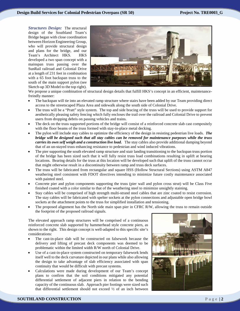
Structures Design: The structural design of the Southland Team’s Bridge began with close coordination between Horizon Engineering Group, who will provide structural design and plans for the bridge, and our Team’s Architect HKS. HKS developed a two span concept with a mainspan truss passing over the SunRail railroad and Colonial Drive at a length of 231 feet in combination with a 65 foot backspan truss to the south of the main support pylon (see Sketch-up 3D Model to the top right). We propose a unique combination of structural design details that fulfill HKS’s concept in an efficient, maintenance-freindly manner: • The backspan will tie into an elevated ramp structure where stairs have been added by our Team providing direct
access to the streetscaped Plaza Area and sidewalk along the south side of Colonial Drive. • The truss will be a “Pratt” style system. The top and side bracing of the truss will be used to provide support for
aesthetically pleasing safety fencing which fully encloses the trail over the railroad and Colonial Drive to prevent users from dropping debris on passing vehicles and trains.
• The deck on the truss supported portions of the bridge will consist of a reinforced concrete slab cast compositely with the floor beams of the truss formed with stay-in-place metal decking.
• The pylon will include stay cables to optimize the efficiency of the design in resisting pedestrian live loads. The bridge will be designed such that all stay cables can be removed for maintenance purposes while the truss carries its own self weigh and a construction live load. The stay cables also provide additional damping beyond that of an un-stayed truss enhancing resistance to pedestrian and wind induced vibrations.
• The pier supporting the south elevated ramp structure and stair landing transitioning to the backspan truss portion of the bridge has been sized such that it will fully resist truss load combinations resulting in uplift at bearing locations. Bearing details for the truss at this location will be developed such that uplift of the truss cannot occur that might otherwise result in a discontinuity between ramp and truss deck surfaces.
• The truss will be fabricated from rectangular and square HSS (Hollow Structural Sections) using ASTM A847 weathering steel consistent with FDOT directives intending to minimize future costly maintenance associated with painted steel.
• Concrete pier and pylon components supporting the truss (pier wall and pylon cross strut) will be Class Five finished coated with a color similar to that of the weathering steel to minimize unsightly staining.
• Stay cables will be comprised of high strength multi-strand steel cables that are zinc coated to resist corrosion. The stay cables will be fabricated with spelter sockets at the pylon connections and adjustable open bridge bowl sockets at the attachment points to the truss for simplified installation and tensioning.
• The proposed alignment has the North side main span pier in CFRC R/W, allowing the truss to remain outside the footprint of the proposed railroad signals.
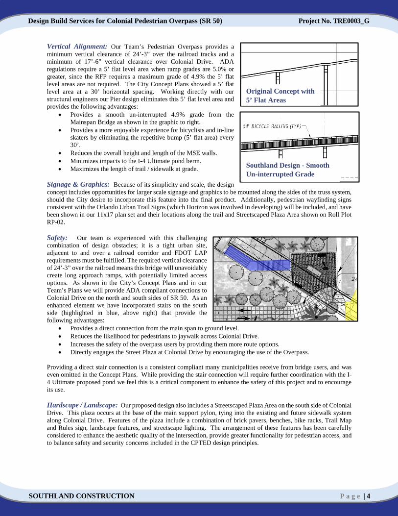
The elevated approach ramp structures will be comprised of a continuous reinforced concrete slab supported by hammerhead style concrete piers, as shown to the right. This design concept is well-adapted to this specific site’s considerations: • The cast-in-place slab will be constructed on falsework because the
delivery and lifting of precast deck components was deemed to be problematic within the limited width R/W north of Colonial Drive.
• Use of a cast-in-place system constructed on temporary falsework lends itself well to the deck curvature depicted in our plans while also allowing the design to take advantage of slab efficiency associated with span continuity that would be difficult with precast systems.
• Calculations were made during development of our Team’s concept plans to confirm that the soil conditions mitigated any potential differential settlement of adjacent piers in relation to the bending capacity of the continuous slab. Approach pier footings were sized such that differential settlement should not exceed ½ of an inch between

Design Build Services for Colonial Pedestrian Overpass (SR 50) Project No. TRE0003_G
SOUTHLAND CONSTRUCTION P a g e | 3
adjacent piers. Analysis of the proposed slab indicates that bending moments associated with differential pier settlement would be at no greater than 10 percent of the ultimate load moments which is within acceptable limits.
At locations where the ramp structures are approximately less than 10 feet in elevation, the trail will be constructed on a MSE (Mechanically Stabilized Earth) fill volume. The trail surface on the MSE fill volume will be comprised of a reinforced concrete slab on grade cast integral with the wall coping. • Foundations for the south ramp approach and the pier and pylon supporting the mainspan truss south of Colonial
Drive will consist of precast pre-stressed concrete piles driven to required capacities. • Square precast concrete pile foundations were selected such that the proposed pond liner can be sealed effectively
around the perimeter of each pile. • The deep foundations will transmit foundation loads beyond the depth of the proposed liner avoiding undesirable
bearing pressure that might otherwise be exerted on the liner by use of spread footing type foundations at these locations.
Foundations for the north approach ramp and north mainspan pier will consist of spread footings. • The size of the spread footings will be determined to maintain appropriate allowable service and ultimate bearing
pressures required for limiting differential settlement to a level appropriate for the ramp deck construction and also maintain stability of the structure.
• Use of spread footing foundations for the north ramp approach and mainspan pier is also very desirable for avoidance of noise and vibration associated with driven pile foundations. Considering the close proximity to the SteelHouse building, excessive vibration and noise associated with driven pile foundations should be avoided to ensure the building is not damaged and nearby residences are not subjected to excessive noise.
Incorporating Aspects of I-4 Ultimate: Orlando’s new landmark will be identified through its own uniqueness, while it successfully incorporates the aesthetic character of historical references, neighboring structures, and the nearby I-4 Ultimate project components. To that end, this designs’ solution incorporates basic elements and colors from the ‘BA8’ design character into the piers and MSE wall supports of the walkway systems on the north and south sides of the bridge crossing. These walkways lead up to the bridge crossing and form a backdrop that accentuates the simple and clear forms of the bridge system. All elevated approach ramps, stairs and MSE wall supported trail sections will include 54 inch safety railings with handrails conforming to FDOT Index 862. Trail Design: The south pier was positioned to meet the required 16’ lateral offset from the edge of the travel lanes and be no closer than the City’s conceptual design which is located within the SR 50 R/W. Additionally, in response to the Addendum issued on March 4, 2016, the mainspan alignment was modified per the FDOT request to avoid placing the pedestrian bridge over the top of the rail road signal in both the WB and EB travel directions for Colonial Drive. The north pier will be inside the CFCR R/W and will provide the 18’ minimum horizontal clearance and a crash wall will be provided. On the south side of Colonial Drive the location of the existing OUC underground oil-filled transmission electric line and the future I-4 Ultimate drainage pond and pipes were reviewed. In order to provide clearance from the OUC line and minimize impacts to the I-4 Ultimate drainage pipes the alignment was revised utilizing a 100’ radius curve, which will provide a gentle flowing alignment. Through our coordination and discussions with the SteelHouse management, the easement area for the proposed pedestrian bridge ramps is frequently used by the local residents as a dog walk area. In order to provide them a wider / flatter area, our Team has re-aligned the sidewalk connection from the ramps adjacent to the eastern R/W which can be seen on Roll Plot RP-01. The relocated sidewalk will provide the locals with a walking area and a graded out area to collect stormwater. As the 12’ proposed concrete trail approaches Orange Ave there, is a large OUC vault in the existing easement. As shown to the right, our Team has centered the proposed trail on the OUC vault. While the OUC vault is an ADA compliant surface, the re-aligned trail will provide an area on both sides to allow roller bladders or bicyclists a less bumpy option around the vault. Additionally, centering the trail will reduce the potential for concrete to crack.
OUC Oil Filled Transmission
Design Build Services for Colonial Pedestrian Overpass (SR 50) Project No. TRE0003_G
SOUTHLAND CONSTRUCTION P a g e | 4
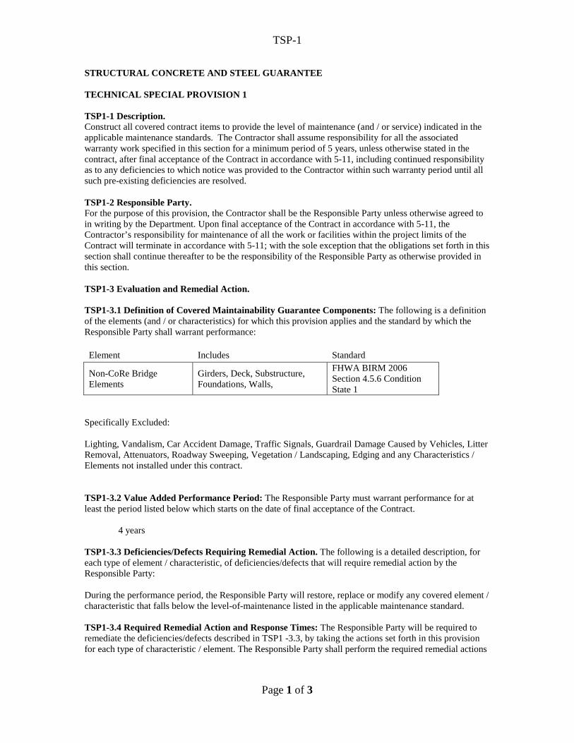
Vertical Alignment: Our Team’s Pedestrian Overpass provides a minimum vertical clearance of 24’-3” over the railroad tracks and a minimum of 17’-6” vertical clearance over Colonial Drive. ADA regulations require a 5’ flat level area when ramp grades are 5.0% or greater, since the RFP requires a maximum grade of 4.9% the 5’ flat level areas are not required. The City Concept Plans showed a 5’ flat level area at a 30’ horizontal spacing. Working directly with our structural engineers our Pier design eliminates this 5’ flat level area and provides the following advantages:
• Provides a smooth un-interrupted 4.9% grade from the Mainspan Bridge as shown in the graphic to right.
• Provides a more enjoyable experience for bicyclists and in-line skaters by eliminating the repetitive bump (5’ flat area) every 30’.
• Reduces the overall height and length of the MSE walls. • Minimizes impacts to the I-4 Ultimate pond berm. • Maximizes the length of trail / sidewalk at grade.
Signage & Graphics: Because of its simplicity and scale, the design concept includes opportunities for larger scale signage and graphics to be mounted along the sides of the truss system, should the City desire to incorporate this feature into the final product. Additionally, pedestrian wayfinding signs consistent with the Orlando Urban Trail Signs (which Horizon was involved in developing) will be included, and have been shown in our 11x17 plan set and their locations along the trail and Streetscaped Plaza Area shown on Roll Plot RP-02. Safety: Our team is experienced with this challenging combination of design obstacles; it is a tight urban site, adjacent to and over a railroad corridor and FDOT LAP requirements must be fulfilled. The required vertical clearance of 24’-3” over the railroad means this bridge will unavoidably create long approach ramps, with potentially limited access options. As shown in the City’s Concept Plans and in our Team’s Plans we will provide ADA compliant connections to Colonial Drive on the north and south sides of SR 50. As an enhanced element we have incorporated stairs on the south side (highlighted in blue, above right) that provide the following advantages:
• Provides a direct connection from the main span to ground level. • Reduces the likelihood for pedestrians to jaywalk across Colonial Drive. • Increases the safety of the overpass users by providing them more route options. • Directly engages the Street Plaza at Colonial Drive by encouraging the use of the Overpass.
Providing a direct stair connection is a consistent compliant many municipalities receive from bridge users, and was even omitted in the Concept Plans. While providing the stair connection will require further coordination with the I-4 Ultimate proposed pond we feel this is a critical component to enhance the safety of this project and to encourage its use. Hardscape / Landscape: Our proposed design also includes a Streetscaped Plaza Area on the south side of Colonial Drive. This plaza occurs at the base of the main support pylon, tying into the existing and future sidewalk system along Colonial Drive. Features of the plaza include a combination of brick pavers, benches, bike racks, Trail Map and Rules sign, landscape features, and streetscape lighting. The arrangement of these features has been carefully considered to enhance the aesthetic quality of the intersection, provide greater functionality for pedestrian access, and to balance safety and security concerns included in the CPTED design principles.
Original Concept with 5’ Flat Areas
Southland Design - Smooth Un-interrupted Grade

Design Build Services for Colonial Pedestrian Overpass (SR 50) Project No. TRE0003_G
SOUTHLAND CONSTRUCTION P a g e | 5
Our review of the City’s Conceptual Plan shows the proposed 12’ trail connection leading directly into a proposed driveway at SR 50 that provides access the pond and railroad R/W as shown in the graphic to the right. Our Team re-aligned the proposed 12’ trail to connect directly with the 15’ sidewalk that the I-4 Ultimate project will construct as shown on the previous page. Our proposed 12’ concrete trail will follow the Downtown Orlando Streetscape Guidelines (Treatment 4: Window Pane Sidewalk Streets). The integrated Streetscaped Plaza Area will utilize brick pavers with a 12” wide ribbon curb around outside. Additionally, the Streetscaped Plaza Area was specifically designed in and around the mainspan bridge pier to provide a user-friendly meeting place and minimize long term maintenance. Brick pavers will visually separate the space and provide a long term ground cover. Aesthetic Lighting: Integrated layers of lighting plays an important underlying role in communicating the message of the proposed bridge design to a wider, nighttime audience experience. We propose vertical LED lighting to accent the main support pylon, reinforcing the architectural concepts and composition into the night. The use of color changing LED lighting on the main support pylon signifies it as an important marker that relates to the scale of the city. All light sources are concealed within the surface of the structure to create a glowing effect that will illuminate the entire surface of the pylon, washing it in a multitude of colors. On the bridge itself, indirect light fixtures mounted in the bridge deck will illuminate the walkway to provide a well-lit environment for pedestrians while shielding drivers on the roadway below from glare. The placement of these lights will also create an internal glow across the length of the truss to highlight its scale and significance. Lighting on the elevated walkways at the north and south sides of Colonial Drive will consist of pole mounted fixtures that are lower than the truss itself, illuminating the walkways in a manner that supports safety and security needs without impacting the adjacent properties. Decorative up-lighting is also included at the concrete piers beneath the elevated walkways, highlighting the walkway systems on the north and south sides of Colonial Drive and accentuating the extent of the walkways, psychologically connecting them to the ground. To achieve these effects, we propose the fixture types and locations shown on Roll Plot RP-02. In addition, the visual impact of the proposed lighting system is shown on the 11x17 Sheet R-2, which utilizes the proposed fixture types and locations. Underdeck Lighting: The widening of SR 50 as part of the I-4 Ultimate project is installing a lighting system along the north side of SR 50 and retaining the existing lighting system along the south side of SR 50. This lighting design was imported into AGI32 and the proposed roadway condition was modeled to generate a baseline. The baseline was then analyzed with the proposed pedestrian bridge to determine if the bridge shadow would have an effect on SR 50 lighting levels. The results of the analysis show the proposed pedestrian bridge has minimal impact on the lighting levels on SR 50 and minimum FDOT illumination criteria is still maintained. As such, underdeck lighting will not be required. CCTV Design: An ITS design will be provided to install CCTV cameras east of the pedestrian overpass. In addition to the requirements of the RFP, we propose the following:
• Install 12 SM fiber optic drop cable between Orlando Hub 5 (located east of Orange Avenue) and the proposed CCTV location (east of the pedestrian overpass). Managed field ethernet switches will be placed inside the CCTV cabinet and Orlando Hub 5 to generate optical signals.
Original Concept
terminated Trail into a
Driveway from SR 50

Design Build Services for Colonial Pedestrian Overpass (SR 50) Project No. TRE0003_G
SOUTHLAND CONSTRUCTION P a g e | 6
• Two cameras will be placed on the proposed pole. One camera will be placed at 20 feet to see under the pedestrian overpass and the I-4 bridge. The 20-foot height will prevent vandalism to the camera and make it maintainable from a bucket truck. A second camera will be installed at 55 feet to see over the pedestrian overpass, over the I-4 bridge, and along the approach ramps. A camera lowering device will be provided for ease of maintenance. We will coordinate with the City on the lower camera height for approval as required by the RFP. The camera heights will be adjusted based on the camera sighting study.
• Power for the CCTV camera will be obtained from the lighting system load center to eliminate the need for an additional power source.
Drainage / Environmental Design: Our Team proposes an efficient drainage system that reduces maintenance issues: • ADA compliant drainage inlets will be provided at each end of the mainspan truss prior to water flowing over the
truss expansion joints and onto the elevated approach ramps. • Water from the drains will be collected by a pipe system that will be cast into the piers to avoid unsightly
externally attached pipes. • Pipes will discharge into the proposed drainage pond to the south and a swale to be constructed under the north
approach ramps. • Deck grades of the elevated approach ramp structure and MSE wall supported trail will be sloped such that water
discharges directly over the edges of the slabs. • V-grove chamfers will be provided along the underside edge of the ramp deck slabs and wall coping to direct
water away from the sides of piers and the face of MSE wall panels. • The existing exfiltration system on the north side of the SteelHouse property will be avoided. • This project qualifies for a permit exemption from the SJRWMD since it is a recreational trail project and there
are no wetland impacts. Design Coordination Plan Minimizing Design Changes: Our Team has been proactive in contacting the project stakeholders, identifying their concerns and updating our proposed design to minimize future changes. The key project stakeholders and the main coordination efforts are further outlined below: Central Florida Rail Corridor: The railroad tracks upon which SunRail operates are owned by the Central Florida Rail Corridor (CFRC), which is an FDOT entity. In response to our Team’s request to meet to discuss this project, CFRC staff indicated that their policy was that they would not meet with competing teams for a project under procurement. Based on published regulations, the Addendum of March 4, 2016 and the Airspace Agreement (and attachments) provided with the RFP, we anticipate design coordination with SunRail / CFRC to include the following: • We will provide a main span bridge design with 24’-3” of vertical clearance from the top of the rail elevation for
the new rail crossings being provided by CFRC for the widening of SR 50. • Per the Addendum of March 4, 2016, the horizontal alignment of the main span will not be located within the
footprint of the railroad signals and gates provided by CFRC for the new crossing. • We will submit a bridge design and erection plan for review that will comply with CFRC’s Maintenance of Way
Instructions (MWIs), design criteria and the Airspace Agreement. • The main span truss enclosure system will prevent objects from being dropped on to the tracks and SR 50. • North of SR 50, a 5’ decorative fence will be provided to delineate CFRC R/W and prevent pedestrians from
wandering onto the railroad tracks. South of SR 50, I-4 Ultimate pond fencing will perform this function. • The portions of the ramp on the North side within the CFRC R/W will have an 8’ decorative fence to prevent
debris from being dropped onto the railroad tracks which is shown on Roll Plot RP-02. I-4 Ultimate: SGL Constructors (SGL) is the joint venture responsible for construction of the I-4 Ultimate project. Our Team met with SGL staff members Dwayne Kyle (Roadway Design-Build Manager), Shelley Gisclar (Area 2 Coordination Engineer) and Dave Erickson (Project Engineer Area 2) to discuss coordination between the two projects. The team also conferred with Carlos Lopez (HDR I-4 Ultimate Drainage Design Lead). We anticipate inter-project design coordination to include: • SGL is constructing a liner in proposed pond P-15 to separate stormwater from contamination plumes in the area.
It is currently anticipated that the liner will be in place by the time foundation work for this project begins. We will design liner repairs, boots or modifications that are approved by the I-4 Ultimate team and supply the intended level of separation between storm and ground water.

Design Build Services for Colonial Pedestrian Overpass (SR 50) Project No. TRE0003_G
SOUTHLAND CONSTRUCTION P a g e | 7
• We will coordinate any additional pond design modifications performed by the I-4 Ultimate team required to provide for the main span pier foundations, the south ramp system, the stair connection and the StreetPlaza Area.
• I-4 Ultimate is providing landscaping and fencing in the project area bounded by SR 50, Concord St, Garland Ave and CFRC R/W. We will coordinate a landscaping design that effectively takes advantage of available, remaining pond space and complements our bridge, ramp and wall design concept.
SGL has drawn its senior staff from personnel that are from Central Florida. Southland and Horizon have long-standing relationships with Dave, Dwayne, Shelley and other anticipated SGL participants. In addition, Horizon Engineering Group is the designer for Area 4D and has access to up-to-date design information for I-4 Ultimate, as well as knowledge of procedures and decision-making. We are familiar with the required SGL Safety training program. We look forward to regular progress meetings that allow us to follow up on the I-4 Ultimate coordination required between the two projects. SteelHouse: Our Team met with Marlene Adeli, the Property Manager for SteelHouse Apartments (SteelHouse) to discuss the project. Design coordination is anticipated to include: • SteelHouse currently utilizes the
trail easement as a recreational and walk area for the complex’s estimated 90 pets. They have requested that any available, remaining easement area be preserved for this use. As shown on our Team’s Roll Plot (and shown in green in the graphic above) the sidewalk connection has been aligned to provide a useable green space for a dog walk area.
• SteelHouse has expressed an interest in possibly maintaining and irrigating any proposed dog walk areas. • SteelHouse currently maintains palm trees and bamboo in the approximate 5’ zone between the easement line and
the parking garage. We committed to providing the elevations and design information necessary for the SteelHouse to decide ahead of time whether this landscaping would survive after construction, or should be removed before we begin.
• SteelHouse maintains an exfiltration system underneath their north alley which borders the trail easement area running east-west between Orange Ave and CFRC R/W. Our ramp walls in this area will be designed not to interfere with this existing drainage system.
• An 8’ decorative fence will be provided on portions of the ramp on the North side to prevent climbers passing between the SteelHouse parking garage and the ramp since the separation between the building and the ramp narrows, this is shown on Roll Plot RP-02. SteelHouse will be consulted on this fence’s design.
Our Team is fully prepared to provide exhibits, design data and staff time to support any public meetings scheduled by the City to inform and coordinate with local residents and businesses. Geotechnical Investigation Plan: The subsurface soil conditions in the vicinity of the proposed bridge structure generally consist of loose to medium dense sands and silty sands in the upper 40 feet, underlain by very loose to loose clayey sands and soft clays to approximate depths of approximately 60 feet. Below, very loose to loose silty sands underlain by stiff to hard clays were encountered and extended to the boring termination depths of approximately 120 to 130 feet. Based on our experience in the project area and the existing subsurface soil conditions, both shallow and deep foundations are considered suitable foundation systems for support of the proposed bridge structure:
1- NBRs between 100 to 220 tons can be accommodated with prestressed concrete driven piles with production lengths of less than 105 feet. Exact sizes and production lengths will be determined during design.
2- For design of shallow foundations, a maximum allowable bearing pressure of 3,000 psf is recommended (i.e. Factored Bearing Resistance QR = 4,000 psf). The total settlement of the shallow foundations is anticipated to be on the order of 1 inch or less. The differential settlements between foundations are anticipated not to exceed ½ inch.
Spread footings are proposed North of SR 50 to mitigate construction impacts to SteelHouse. South of SR 50, piling is proposed to mitigate impacts to the I-4 Ultimate pond liner.
Easement Used as a Dog Walk Area

Design Build Services for Colonial Pedestrian Overpass (SR 50) Project No. TRE0003_G
SOUTHLAND CONSTRUCTION P a g e | 8
Permanent Walls: Permanent MSE walls are appropriate for the bridge ramps. Based on the information provided, immediate settlement of the approach embankment is estimated to be on the order of 1 to 2 inches and the long-term settlement of the embankment is anticipated to be on the order of ½ inch or less. Load Test Program: The load test program for the driven piles will include dynamically tested piles using a Pile Driving Analyzer (PDA). Analyses and testing services will be completed in accordance with the requirements of RFP and the FDOT Structures Design Guidelines and SSRBC 455. The dynamic pile load test program for the planned pile foundations will include the following: • Perform a pile driving simulation analysis utilizing the Contractor’s proposed driving system and the Wave
Equation Analysis Program (WEAP). • Perform an inspection of the Contractor’s mobilized pile driving equipment prior to driving piles. Perform
dynamic load testing on every pile using the Pile Driving Analyzer (PDA). • Perform subsequent Case Pile Wave Analysis Program (CAPWAP) analyses to confirm PDA measured pile
capacities and estimate the pile capacity distribution (end bearing and skin friction resistance). A final report will be prepared to include all of the PDA data and subsequent CAPWAP analyses obtained during the pile installation program. The report will be made available to the Department. The pile installation data will be jointly signed and sealed by the Engineer responsible for the PDA testing and the Geotechnical Foundation Design Engineer of Record. All work will be in accordance with the project specifications including preparation of Foundation Certification Packages. Minimizing Impacts Through Design to Environment / Public: This section of Colonial Drive is one of the busiest segments within the City of Orlando and our Team will implement the following features to minimize impacts to the environment and public:
• A SWPPP will be submitted to the City for review and approval. These erosion and sedimentation control measures will be coordinated with the I-4 Ultimate Team to avoid overlapping features and will be installed prior to construction to prevent disturbed soil from leaving the project site.
• Our Team’s Traffic Control Plan will include vehicular and pedestrian detours that will be utilized only when needed. Additionally, all lane closure and detour routes will be coordinated with the I-4 Ultimate Team to avoid overlapping or confusing detours to the public.
• Our Traffic Control Plan will include barricading off the work zone and / or partially completed bridge /ramp segments to prevent pedestrians from entering the work zone.
Minimizing Impacts Through Design to Adjacent Properties / Structures: The constrained R/W and easements provided for the project necessitate close construction corridors and our Team has therefore taken the following design measures to minimize impacts to adjacent properties / structures:
• Use of spread footing foundations for the north ramp approach and mainspan pier is also very desirable for avoidance of noise and vibration associated with driven pile foundations.
• Considering the close proximity to the SteelHouse apartments, excessive vibration and noise associated with driven pile foundations should be avoided to ensure the building is not damaged and nearby residences are not subjected to excessive noise.
• Our proposed wall system on the north side of the SteelHouse property avoids their existing exfiltration system and light poles.
• The mainspan north pier location provides the minimum 18’ offset and the required crash wall. • The drainage on the south side of Colonial Drive will be directed into the I-4 Ultimate Pond P-15 and on the
north side a swale has been provided under the ramp approaches. Traffic Control Plan: During placement of the Pedestrian Bridge Main Span detours will be utilized for both pedestrian and vehicular traffic. Coordination will also be required with rail services that operate along the Railroad Corridor. Advance notice of detours will be given to the public through the use of Portable Changeable Message Signs. Vehicular Detours will include the following:

Design Build Services for Colonial Pedestrian Overpass (SR 50) Project No. TRE0003_G
SOUTHLAND CONSTRUCTION P a g e | 9
Vehicular traffic traveling eastbound on Colonial Drive will be detoured south on Hughey Ave to Amelia St. to Magnolia Ave and back to Colonial Drive.
Colonial westbound traffic will be detoured south on Orange Ave to west on Concord Street to north on Garland Ave and back to Colonial Drive.
Pedestrian Detours will include the following:
Pedestrian traffic traveling east on Colonial Drive will be detoured south down Garland Ave to Amelia Street to Orange Ave then back onto Colonial Drive.
Pedestrian traveling west on Colonial will be detoured the opposite direction.
During construction, our Team will coordinate closely with the I-4 Ultimate team regarding any signage needed for detours that could possibly conflict with I-4 Ultimate MOT signage. We will also coordinate any I-4 Ultimate detours that could possibly be utilizing Colonial Drive. Within the project limits resident parking garages are present. During detours, we will maintain access for local traffic to and from their residence. We will also maintain emergency vehicle access under emergency situations. A U-turn will be provided for those vehicles that accidently travel onto the project limits but are not residents. Utility Coordination and Design: We have a plan to successfully coordinate this project’s critical utility issues in a fast-tracked timeframe. Based on our review of the RFP, our proposed design and direct consultations with the UAOs, we have identified the following critical utility issues: North of SR 50, on the West side of the SteelHouse, OUC Distribution maintains in the trail easement six existing
poles which support both OUC electric lines and Bright House fiber optic cables. In this same area, TECO has a 2” service. These facilities are in conflict with the column supported ramp system.
West of Orange Ave, on the North side of the SteelHouse, OUC Distribution maintains underground electric cables in conduit. These facilities are in conflict with the wall supported ramp system.
North of SR 50, in CFRC R/W, Level 3, Verizon Business (fka MCI) and FDOT/Sunrail maintain underground fiber optic communications systems. Per the Clarification of March 4, 2016, these facilities are in conflict with the North side main span pier. OUC Distribution also maintains some smaller services within the CFRC R/W.
There are other facilities along SR 50 and Garland (OUC Transmission’s oil-cooled line being the most important example), but our proposed design avoids conflicts with those facilities. We have solid working relationships with all these utilities and have performed extensive proposal phase coordination: On the West side of the SteelHouse, within the trail easement, OUC Distribution, TECO, Verizon Business and
Bright House have a plan to relocate their facilities underground. We have received updated cost estimates from them for this reimbursable work.
On the North side of the SteelHouse, OUC Distribution has a plan to vertically relocate their existing underground facilities out of the way of the wall excavations. Their existing pull box location will be coordinated with the at grade trail design. We have received a cost estimate from them for this reimbursable work.
Within CFRC R/W, Level 3 has (2) 1.5” HDPE and (1) 1.25” HDPE conduits with 2 fiber optic cables along the east side of the existing railroad tracks. Verizon Business (fka MCI) has two buried fiber optic cable runs within the railroad R/W, with the eastern most run being impacted. Design phase investigations will be required to determine the disposition of these utilities, but most will have to be relocated.
OUC Distribution has developed a plan and price to provide power for the lighting and CCTV systems.
North of Colonial Drive. Utilities in easement and CSXT
Work ZoneEB DetourWB Detour

Design Build Services for Colonial Pedestrian Overpass (SR 50) Project No. TRE0003_G
SOUTHLAND CONSTRUCTION P a g e | 10
Upon award of the contract, our utility coordination efforts will be led by Melonie Schwartz, Utility Coordination Manager at Horizon, who will organize early and continuous individual meetings and site visits with UAOs to follow-up on our proposal phase activities in an accelerated manner: • Subsurface investigations will identify the exact relationship between existing alignments and our proposed
design. • Design submittals and modifications will be submitted to the UAOs for review. • A utility conflict matrix will be developed. • Utility relocation designs and schedules will be procured and coordinated with the project design. • Project documentation (work schedules, agreements, reimbursement agreements, permits, etc.) will be developed,
reviewed and executed. By starting early to thoroughly work through the details of the utility issues, we will contribute to the overall success of the project. Construction Technical Approach Construction Coordination Plan: CFRC: Design phase coordination with CFRC will be followed up with thorough construction phase coordination: • The procurement and construction of the grade crossing, signals and gates at SR 50 is anticipated to be completed
by October 2016 to accommodate the construction schedule for the SR 50 widening. Our own activities will be coordinated so there is an efficient, safe sharing of the available work space by all parties adjacent to SR 50.
• Foundation construction inside CFRC R/W will be properly shored in accordance with their requirements. • Work inside CFRC R/W that is more than 25’ from the centerline of the tracks will be conducted under a valid
right-of-entry which defines safe work procedures that are compatible with on-going train operations. In particular, the weight of the truss will be matched to grade crossing and crane capacities.
• Work inside CFRC R/W that is closer than 25’ from the centerline of the tracks (including over the tracks) will be performed according to the applicable, approved plans, right-of-entry and in conjunction with the flagmen and inspectors provided by CFRC. Participating personnel will possess valid Safety Awareness Training and Security Clearances provided by e-Railsafe Shortline. In addition, this work will be scheduled on nights and weekends to avoid active SunRail, Amtrak and CSXT operations.
I-4 Ultimate: Design phase coordination with I-4 Ultimate / SGL will be followed up in the construction phase with the following: • SR 50 will be widened beginning in the Spring of 2016. Our construction schedule will be coordinated to share
the work zones adjacent to SR 50. • The pond in which the south ramp system is located is anticipated to be built in Spring of 2016. Therefore, it is
anticipated that by the time our construction begins, we will be working in a completed pond. • All activities in SGL-controlled R/W will be performed by personnel oriented and certified in the I-4 Ultimate
Work Zone Safety Requirements. • We will have to implement traffic detours to perform overhead bridge work over SR 50 and CFRC tracks. SGL
also needs detours to perform overhead bridge work for I-4 over SR 50. We will coordinate mutually agreeable times that either avoid conflicts between our schedules, or allow us to safely and efficiently share detour implementations.
• SGL is not aware of any extra I-4 R/W under its control that will be available for this project to utilize as a staging or office area, but we can revisit this issue with them in the future.
• We will modify the pond liner to accommodate foundations within the liner limits. For the ramp foundations, we will cut holes in the liner and drive pilings through them. Once the pile cap is poured, the liner will be patched to wrap around the piles. We will use the same supplier for the original liner to obtain patching materials and installation procedures. For the wall supported ramp sections, the liner will be excavated and folded up to the wall levelling pad alignment and elevation, in coordination with the original liner design.
SteelHouse: Construction activities will be conducted to mitigate impacts to the SteelHouse residents: • SteelHouse expressed a desire for us to avoid work at night that might disturb the residents’ sleep. While there
are some activities that unavoidably need to be at night (e.g. bridge construction over SR 50 and the railroad), we certainly will coordinate daytime working hours where that is possible.
• SteelHouse has indicated that their delivery alley, which runs parallel to the trail easement, may possibly be shared to accommodate construction activities on the east-west ramp, if schedules are appropriately coordinated.
• Our field staff will work with the SteelHouse managers to protect existing landscaping and irrigation that will remain. Also, where safety practices and space allow, we will coordinate the use of temporary dog walk ing areas during construction.

Design Build Services for Colonial Pedestrian Overpass (SR 50) Project No. TRE0003_G
SOUTHLAND CONSTRUCTION P a g e | 11
• All of the foundations surrounding the SteelHouse are spread footings. This will mitigate vibration and noise issues for the residents. Pile driving taking place across SR 50 in the I-4 Ultimate pond will be performed during daytime hours.
Safety: Southland will create a safe working environment for the Colonial Drive Pedestrian Bridge project by developing and implementing a comprehensive safety plan that incorporates our company’s normal safety practices and addresses site-specific issues. The safety planning process is intended to address both on-site worker safety and the safety of the general public using SR 50 and adjoining local roadways. Southland has an in-place safety plan which is the starting point for the safety planning process. This plan will identify each project participant’s role in regards to safety, defines lines of communication, describes resources available to enhance safety and lays out accident reporting and investigation procedures. Our safety policy and default plan specifically address maintenance of traffic, visitors, material hazards, training, demolition, trenches, equipment operation, required safety equipment, ventilation, enclosed spaces, inspections and first aid. Our specific safety rules, which are edited and designed to be easily understood by our field employees, are developed from OSHA standards, manufacturer recommendations, industry resources, Florida Law, common sense and experience. Southland’s safety policy will be customized to address issues specific to the Colonial Drive Pedestrian Bridge worksite: • Workers will be certified and trained according to special requirements and instructions received from CFRC and
I-4 Ultimate / SGL. • Descriptions of anticipated contamination plumes and response procedures for the specific materials will be
identified in the Safety Plan. • Crane capacities will be carefully matched to piece weights and recorded in the formal Erection Plan. Also, in
relation to bridge construction, an emphasis will be placed on developing hour by hour schedules for each night’s activities to avoid potential lane closure time overruns.
• Efficient flow of vehicular traffic is important to the City. For that reason, our Safety Plan will incorporate the portions of the maintenance of traffic plans regarding holidays, special events, construction vehicle ingress / egress from SR 50, lane closure hours, procedures and notifications to educate workers as to their responsibilities and resources. All design and construction activities will conform to FDOT standards.
• Southland’s Safety Director, Dickie Stegall, will be responsible for creating and implementing the Safety Plan which will be submitted at the Preconstruction Conference. She will ensure that our employees and subcontractors are aware of site specific issues. She will perform weekly safety inspections and interface with the City in regards to security and safety throughout the project.
Structures and Trail Construction: Access and Work Methods: Construction of the bridge, ramps and trail are characterized by the following access conditions:
Area Section Width R/W Width Comments Main Span over SR 50 / CFRC
Bridge 12’ N/A The truss will be assembled off-site, rolled into position on SR 50 and lifted by hydraulic cranes during a short shutdown of SR 50, at a time approved by CFRC.
West Side of SteelHouse
Ramp with Switchback
20’ 35’ The main span pier will be in CFRC R/W and will be built in conjunction with flaggers. For the rest of the ramp system, work will generally remain 25’ from the center of the tracks.
North Side of SteelHouse
Ramp 12’ 20’ SteelHouse Alley may be available for some activities.
SR 50 to Concord St
Ramp and Switchback
Varies (12’ to 24’)
Up to 100’, but it will be in an active pond.
The pond must remain operational during construction, but there is some CFRC R/W >25’ from center of tracks that may be available on a limited basis.
Construction of the main span over SR 50 / CFRC will take place at night, as that is the only way to provide access for the cranes and dollies required to hoist the pre-assembled truss into position on the piers. However, these types of operational restrictions are not unusual for a bridge over a major state highway and railroad. Construction of the ramp and switchback system in the I-4 Ultimate Pond P-15 will take place during the daytime, using the types of equipment and techniques normally encountered on a typical construction project. The pond, which must remain operational during construction, will have to be modified to provide equipment access and some supplementary access from abandoned Gertrude Way may be possible per CFRC’s regulations, in areas greater than

Design Build Services for Colonial Pedestrian Overpass (SR 50) Project No. TRE0003_G
SOUTHLAND CONSTRUCTION P a g e | 12
25’ from the centerline of the nearest track. The equipment (cranes, backhoes and material handlers) will operate adjacent to the ramp and switchback areas and will lift materials into place. North of SR 50, construction is more complicated. The main span pier (and one span of the ramp) are within CFRC right-of-way. The foundation excavation will be shored with a system reviewed by CFRC and flaggers will be required for pier construction. For the rest of the ramps in this area, CFRC flagging will not be required. For the entire north ramp area, there is not enough room for cranes and other material handlers to freely operate parallel to the proposed improvements. Therefore, construction in this area will be approached in a unique fashion. For the ramps and walls on the west side of the SteelHouse, deliveries will be via SR 50 and Orange Ave and the ramps will be built span-by-span, with the cranes and other equipment having to back in and out to provide material deliveries. The MSE wall ramp running east-west on the north side of the SteelHouse will be built with a stiff enough backfill to allow vehicles and equipment to operate on top of the walls, as they are built with deliveries from Orange Ave, after work on the west side of the SteelHouse is completed. Dewatering and Contamination: Available geotechnical data indicates that groundwater will be encountered when constructing foundations in the I-4 Ultimate Pond. Given the proximity of existing contamination plumes, we consulted with Larry Sims of L.S. Sims and Associates (LSS&A) to understand contamination issues for this project. LSS&A has been contracted by FDEP to run a permanent dewatering operation north of SR 50 that scrubs contaminates from the Orlando Sentinel plumes. We described our anticipated operations with Mr. Sims and asked what measures we should plan on to deal with contamination. He indicated that given the depth (<10’) and duration (<1 month) of our dewatering activities, there would be no contaminates present in our construction dewatering operations and we would not interact with the plumes which tend to be greater than 30’ deep from existing ground. In the event, however, that contaminates are encountered, LSS&A indicated that the water will be transported by us to their permanent dewatering system for processing. Because LSS&A’s contract includes responsibility for the entire plume, the FDEP would cover the actual cost of cleaning any groundwater we collect. Drainage Construction: The main span deck is cambered at a rate that allows stormwater to run to the ramp areas without any main span conveyance system. Trench drains and conveyance piping will be cast into the ramp decks to convey ramp stormwater to the ground level. In both the pond and the northwest corner of the SteelHouse, there are existing drainage systems that will be slightly modified. Implementation of the Environmental Design and Erosion/Sediment Control Plan: The project will be built in compliance with applicable environmental regulations: • We will submit to FDEP a Notice of Intent in compliance with NPDES regulations. • Erosion control measures will be installed in accordance with the SWPPP that prevent distribution of silt off-site. • The measures will be inspected and maintained weekly, or after a >1/4” rain event. • In the I-4 Ultimate Pond, erosion control measures will be arranged to allow the pond to perform its intended
function during construction. In addition, as detailed in our Design and Construction Coordination sections, the I-4 Ultimate Pond liner will be modified and repaired in compliance with I-4 Ultimate requirements.
• As detailed in our Structures and Trail Construction section, foundations will be built to mitigate impacts from existing contamination plumes.
Implementation of the Maintenance of Traffic Plan: SR 50 traffic will be detoured for the truss to be set. This work will be at night at a time approved by the City, CSX, CFRC and FDOT. The dates will also be coordinated with the I-4 Ultimate team to avoid overlap. The truss will arrive with safety fencing and deck forms already installed. This will reduce the number of SR 50 lane closures required to complete the main span. Some SR 50 and Orange Ave single lane closures will be needed for material deliveries. The exact timing and implementation of these activities will be coordinated with the City, FDOT and the I-4 Ultimate team.
The cast in place shoring and forming system is compatible with equipment that fits between the RR R/W line and the SteelHouse building.

Design Build Services for Colonial Pedestrian Overpass (SR 50) Project No. TRE0003_G
SOUTHLAND CONSTRUCTION P a g e | 13
Utility Coordination and Construction: Utilities are a critical aspect of this project: • OUC Electric has overhead lines on the West side of the SteelHouse that impact ramp foundation and column
construction. • Bright House has cables on OUC’s existing lines. • OUC Electric has underground lines on the North side of the SteelHouse that impact wall construction. • TECO has an existing gas main on the West side of the SteelHouse that impacts ramp foundation construction. • There are existing fiber optic cables in CFRC R/W that impact the North side main span pier. All of these facilities need to be relocated. All have been contacted in the proposal phase to confirm the feasibility of relocating their facilities. During the construction phase, we will organize a teamwork-oriented approach to working with relocation work by Utility Agency Owners (UAOs):
• We will contact them early on to give them time to plan. In addition to the normal written communications, we will meet on site with each relocating UAO for a hands-on review of dimensions, access and potential issues.
• We will follow up with them regularly for mutual updates and brainstorming. • We will include UAOs at weekly construction meetings to encourage collaboration. • We will offer reasonable technical and construction assistance (survey layout, MOT, custom site preparation)
that makes their work more efficient. This positive, proactive approach has worked on many similar projects and we look forward to making the utility relocation work for this project a success. Schedule Narrative: The project’s phases will be organized to efficiently achieve an accelerated completion date, meeting all of our obligations to the City and third party stakeholders: Survey & Geotech: Immediately upon notice to proceed, the site will be surveyed and a geotechnical investigation will be performed. The purpose of these tasks is to confirm the assumptions used for the proposal design and develop any data needed to prepare the 90% Design Submittal. 90% Design Submittal: In this phase, the design team will develop details and calculations needed to flesh out and complete the design. Design Quality Control checking will be performed before the plans are sent to third parties for review. Design Coordination: This is the most critical design phase. The 90% design will be distributed to reviewing stakeholders such as SteelHouse, CFRC / SunRail, I-4 Ultimate, the City of Orlando Appearance Review Board, Utility Agency Owners (UAOs), FDOT and the City’s own Transportation Engineering reviewers. Individual meetings will be scheduled with each stakeholder as needed to receive input and resolve issues if they arise. Construction of the permanent improvements will be dependent upon coordination with each stakeholder. Preliminary Construction: There are some preliminary field activities that are not dependent upon design coordination. Examples include clearing and grubbing and utility relocations. For activities such as these that will not vary based on stakeholder input, they will be scheduled to take place while design is on-going. The most critical utility relocations include: • The existing overhead OUC Electric facilities running parallel to the railroad tracks must be converted to
underground facilities in an alignment that is outside the limits of the proposed spread footings. • BrightHouse Networks must relocate off of OUC Electric’s poles into conduit. • OUC Electric has underground lines that must be relocated to a deeper elevation. • TECO has a line that must be relocated back into SR 50 R/W. • Level 3 and Verizon Business (MCI) has fiber optic cables and there is buried electric line in CFRC R/W that
must be moved out of the way of the North main span pier. 100% Design Submittal: After stakeholder input is received, the plans can be finalized. Based on the pace of stakeholder responses, the submittals will be organized into component sets that allow for acceleration of material procurement and work in the field. North Side Wall-Supported Ramp: Due to the width of the available trail easement on the north side of the SteelHouse property the wall-supported ramps from Sta 210+54.50 to Sta 214+50.00 will be built from west to east, starting at the ramp end bent and working out towards Orange Ave. We believe this work can progress concurrently with both the OUC Electric relocation work and the construction of the north side ramp foundations and columns. However,

Design Build Services for Colonial Pedestrian Overpass (SR 50) Project No. TRE0003_G
SOUTHLAND CONSTRUCTION P a g e | 14
the ramp end bent itself cannot be completed until OUC Electric is fully relocated and that part of the wall must be completed before any ramp deck work takes place. North Side Column-Supported Ramp: Due to the width of the trail easement, this section of ramp will be built span by span, starting at the wall-supported ramp end bent and working out towards SR 50. Equipment will be withdrawn after completion of each span’s foundations, columns and deck to allow another phase of materials to be delivered. None of this work can take place until OUC Electric, Bright House and TECO are relocated and the ramp deck cannot start until the wall-supported end bent is complete. This work, which includes the north main span pier wall, must be completed before the main span truss can be installed. Pond Ramp / Walls / Pylon: All of the work in the I-4 Ultimate pond can be done either before or after the pond and liner are constructed, but it cannot take place concurrently with pond construction itself. Once this site is released to us, the wall-supported ramp and columns can take place concurrently. Column-supported deck construction will begin once the wall-supported end bent is complete. The pylons will be completed before the main span is installed and the truss will be designed with splice sections that facilitate that sequence. The sequence of the work taking place in the pond is not dependent upon any activities taking place north of SR 50, except as it relates to OUC Electric relocation work and scheduling of the main span construction. Main Span: After both the north side and south side main span piers are completed (including the pylons), the main span truss will be installed. The truss will be assembled off the roadway during daytime hours. During nighttime detours coordinated with I-4 Ultimate, CFRC, CSXT, Amtrak, FDOT and the City, the truss over SR 50 will be set in a single piece. The piece of the truss spanning from the pylon pier to the south main span end bent wall will be erected separately. The truss pieces will be installed with stay-in-place deck forms and most of the wire mesh enclosure already installed. Subsequence nighttime lane closures will be utilized to install reinforcing steel, install lighting conduit and fixtures, pour the deck and finalize grab rails and wire mesh fencing. Because the construction of the main span over SR 50 and CFRC is dependent upon completion of the end bents and ramp systems, finalization of the other project elements will take place concurrently with main span work. Innovation Through the development of our Team’s Technical Approach we have integrated numerous innovative and unique solutions into our Concept Plans which are highlighted below:
• Horizon Engineering Group is a member of the I-4 Ultimate Team and has daily contact with all their key decision makers.
• On the South side of Colonial Drive, the trail connection was re-aligned to avoid the proposed FDOT driveway connection.
• The approach ramps will utilize a smooth un-interrupted 4.9% grade that eliminates the repetitive bump (5’ flat area).
• A useable Pet Walk area has been provided under the North Approach ramps adjacent to the SteelHouse apartments for local residents.
• The continuous, cast-in-place ramp deck lowers the profile of the entire ramp system and is well-adapted to be built in limited access conditions, with smaller equipment.
• Effectively utilizing a combination of pile and spread footing foundations to minimize vibration issues and provide effective and economical support of elevated sections.

Design Build Services for Colonial Pedestrian Overpass (SR 50) Project No. TRE0003_G
SOUTHLAND CONSTRUCTION P a g e | 15
• The primary elements of our unique Pedestrian Bridge include a majestic concrete pylon with a sweeping truss.
• Visually, the arc of the great pylon artistically serves as a nod to and embracement of our historic downtown core and Orlando’s skyline.
• The pylon is symbol of strength of our community that supports the long truss.
• The slender tension cable supports echo the strength of the City’s diverse and interconnected neighborhoods, whose fundamental strength as a system are represented within the strong and graceful body of the truss itself.
• The use of color changing LED lighting on the main support pylon signifies it as an important marker that relates to the scale of the city.
• Decorative up-lighting is also included at the concrete piers beneath the elevated walkways, highlighting the walkway systems on the north and south sides of Colonial Drive and accentuating the extent of the walkways, psychologically connecting them to the ground.
• A direct stair connection in provided on the South of Colonial Drive which increases the safety of the users and directly engages the StreetPlaza by encouraging the use of the overpass.
Value Added Southland proposes a comprehensive set of value added guarantees for the City of Orlando:
Guarantee Covered Items Period Standards Structural Concrete and Steel
Truss, Decks, Substructure, Foundations, Walls
4 Years FHWA BIRM 2006 Section 4.5.6 Condition State 1
Lighting Lighting System Components 3 Years FDOT Specifications 715 & 725 Bridge Components Coatings, Bearing Pads and
Expansion Joints 5 Years FDOT Specification 475
FDOT standards are utilized to define the measurable standards for lighting, coatings, bearing pads and expansion joints. Structural concrete and steel components installed under this contract will be analyzed according to AASHTO’s Commonly Recognized (CoRe) Elements Condition States criteria, as defined in Section 4.5.6 of FHWA’s Bridge Inspector’s Reference Manual (BIRM) (2006). Essentially, this criteria establishes a structural element’s status in the process of deterioration. For the 5-year period of the guarantee, we will restore to Condition 1 Status (Protected–Protective systems sound and functioning to prevent deterioration) any of the concrete bride components which might fall into a lower condition. Our team is eager to work with you in producing this significant landmark for the City. In pursuing this project we have put together a dream team of designers and constructors whom we know will strive to deliver a seamless project everyone will be proud of. In selecting our materials; establishing our design vernacular; speaking to stake-holders; reviewing construction to user safety; and, developing a construction plan, we came together using our combined knowledge and experience to create a beautiful, low-risk, prefabricated steel truss pedestrian bridge system that will stand the test of time.

Project No. TRE0003_GDesign Build Services for Colonial Pedestrian Overpass (SR 50)
SOUTHLAND CONSTRUCTION
Section 2: Plans and Technical Special Provisions

Project No. TRE0003_GDesign Build Services for Colonial Pedestrian Overpass (SR 50)
SOUTHLAND CONSTRUCTION
TSPs
TSP-1
Page 1 of 3
STRUCTURAL CONCRETE AND STEEL GUARANTEE TECHNICAL SPECIAL PROVISION 1 TSP1-1 Description. Construct all covered contract items to provide the level of maintenance (and / or service) indicated in the applicable maintenance standards. The Contractor shall assume responsibility for all the associated warranty work specified in this section for a minimum period of 5 years, unless otherwise stated in the contract, after final acceptance of the Contract in accordance with 5-11, including continued responsibility as to any deficiencies to which notice was provided to the Contractor within such warranty period until all such pre-existing deficiencies are resolved. TSP1-2 Responsible Party. For the purpose of this provision, the Contractor shall be the Responsible Party unless otherwise agreed to in writing by the Department. Upon final acceptance of the Contract in accordance with 5-11, the Contractor’s responsibility for maintenance of all the work or facilities within the project limits of the Contract will terminate in accordance with 5-11; with the sole exception that the obligations set forth in this section shall continue thereafter to be the responsibility of the Responsible Party as otherwise provided in this section. TSP1-3 Evaluation and Remedial Action. TSP1-3.1 Definition of Covered Maintainability Guarantee Components: The following is a definition of the elements (and / or characteristics) for which this provision applies and the standard by which the Responsible Party shall warrant performance: Element Includes Standard
Non-CoRe Bridge Elements
Girders, Deck, Substructure, Foundations, Walls,
FHWA BIRM 2006 Section 4.5.6 Condition State 1
Specifically Excluded: Lighting, Vandalism, Car Accident Damage, Traffic Signals, Guardrail Damage Caused by Vehicles, Litter Removal, Attenuators, Roadway Sweeping, Vegetation / Landscaping, Edging and any Characteristics / Elements not installed under this contract. TSP1-3.2 Value Added Performance Period: The Responsible Party must warrant performance for at least the period listed below which starts on the date of final acceptance of the Contract.
4 years TSP1-3.3 Deficiencies/Defects Requiring Remedial Action. The following is a detailed description, for each type of element / characteristic, of deficiencies/defects that will require remedial action by the Responsible Party: During the performance period, the Responsible Party will restore, replace or modify any covered element / characteristic that falls below the level-of-maintenance listed in the applicable maintenance standard. TSP1-3.4 Required Remedial Action and Response Times: The Responsible Party will be required to remediate the deficiencies/defects described in TSP1 -3.3, by taking the actions set forth in this provision for each type of characteristic / element. The Responsible Party shall perform the required remedial actions

TSP-1
Page 2 of 3
within the maximum response times set forth in this provision and which start when written notification is received by the Responsible Party from the Department or when there is an emergency situation, response time starts with the Department’s verbal notification which will be followed up in writing. If replacement components require a lengthy acquisition period, the maximum repair duration as specified in this provision will be extended at the Engineer’s discretion. If the maximum response time will result in the Responsible Party completing the work after the performance period, as specified in TSP1 -3.2, has expired then the expiration date for the affected characteristic / element will automatically be extended to whichever comes first: the end of the maximum response time period or completion of the remedial action. The Responsible Party shall complete all remedial work to the satisfaction of the Engineer. The Statewide Disputes Review Board will resolve any disputes regarding the adequacy of the remedial work. Approval of remedial work does not relieve the Responsible Party from continuing responsibility under the provisions of this Specification. Not less then 7 days prior to beginning any non-emergency remedial work, notify the Engineer in writing of the date when remedial work will begin. Submit a written Work Plan to the Engineer for approval and do not begin remedial work until approval is received. The Work Plan shall propose measures that provide the level-of-maintenance identified in the applicable maintenance standard. The Work Plan shall describe the phases of construction that are planned and generally explain for each phase, the construction methods to be employed. In addition, the work plan shall list the materials that will be incorporated into the permanent remedial work. For emergency situations, the Responsible Party will discuss the Work Plan with the Engineer verbally and the Engineer will issue a temporary approval in order to allow work to begin in a timely manner. A written Work Plan as specified above will be required if the duration of the emergency remedial work extends beyond 72 hours. Perform all remedial work at no cost to the Department. Any issues that represent a threat to public safety will be addressed immediately and continuously until repaired. Other types of issues will be addressed according to a mutually agreed to schedule, usually within 180 days. Remedial measures will be defined in recommendations provided by the Responsible Party, as approved by the Department. TSP1-4 Notification of Deficiencies/Defects and Inspections. The Department will identify deficiencies/defects in a written report that will be transmitted to the Responsible Party along with an official notification of required remedial action if warranted. The Department will also transmit copies of periodic bridge deficiency reports to the Responsible Party as they become available so that the Responsible Party can be aware of a deteriorating condition that may not require immediate remediation but that could give the Responsible Party an opportunity to performed an optional, more economical, preventive action. If an “Emergency Situation” exists, Responsible Party notification will be provided verbally by the Department with written follow-up. In either case, the Responsible Party shall perform remedial actions in accordance with TSP1-3.4. If the Responsible Party fails to, or provides notification that it is unable to, begin work within the time designated in TSP1-3.4 or if the Responsible Party notifies the Department that it is unable to perform an acceptable remedial action, then the Department reserves the right to perform the remedial action at the Responsible Party’s expense. TSP1-5 Disputes Resolution. A statewide Disputes Review Board dedicated to the resolution of value added disagreements will be utilized to resolve any and all disputes that may arise involving administration and enforcement of this specification. The Responsible Party and the Department acknowledge that use of the Board is required and the determinations of the Board for disputes arising out of this specification will be binding on both the Responsible Party and the Department, with no right of appeal by either party, for the purposes of this

TSP-1
Page 3 of 3
specification. Any and all Board meetings after final acceptance of the Contract in accordance with 5-11, shall be requested and paid for by the Responsible Party. The Department will reimburse the Responsible Party for all fees associated with meetings only if the Board rules substantially, as determined by the Board in favor of the Responsible Party, otherwise the Responsible Party shall be solely responsible for all such costs. The term “substantially” is defined as fifty (50) percent of the issues when entitlement is disputed or fifty (50) percent of the total dollar amount when costs associated with such entitlements is disputed. TSP1-6 Value Added Work. During the value added performance period, the Responsible Party shall perform all necessary remedial work described in the Contract. Should an impasse develop in any regard as to the need for remedial work or the extent required, the Statewide Disputes Review Board will render a final decision. The value added obligation for this specification will not apply to deficiencies if any of the following factors are found to be beyond the control of the Responsible Party: Determination that the deficiency was due to the failure of other features not a part of the Contract. Determination that the deficiency was the responsibility of a third party performing work not included in the contract or was the responsibility of an individual(s) that is not under the control of the Responsible Party or Contractor. Determination that the deficiency was caused by an act or event after final acceptance of the project, such as storm damage or vehicle impact, that is not under the control of the Responsible Party or Contractor. TSP1-7 Failure to Perform. Should the Responsible Party fail to timely submit any dispute to the Statewide Dispute Review Board, fail to satisfactorily perform any remedial action, or fail to compensate the Department for any remedial action performed by the Department, as determined by the Board to be the Responsible Party’s responsibility, the Department shall suspend, revoke or deny the Responsible Party’s certificate of qualification under the terms of Section 337.16(d)(2), Florida Statutes, until the remedial work has been satisfactorily performed or full and complete payment for the remedial work made to the Department. Should the Responsible Party choose to challenge the Department’s notification of intent for suspension, revocation or denial of qualification and the Department’s action is upheld, the Responsible Party shall not have it’s qualification suspended until the issue is resolved. TSP1-8 Traffic Control. During remedial action operations, perform all signing and traffic control in accordance with the current edition of the Department’s Design Standards. Provide Maintenance of Traffic during remedial work at no additional cost to the Department. For non-emergency remedial work, the Engineer must approve all lane closures and traffic control plans in advance and notification of lane closures must be made to the Engineer 48 hours in advance. For emergency remedial work and if the Responsible Party requests it, the Department will provide temporary maintenance of traffic (MOT) until the Engineer approves the Responsible Party’s Traffic Control Plan. If MOT is requested, the Responsible Party will reimburse the Department for all temporary MOT costs. In addition, if the urgency of the remedial work is such that the Department must provide MOT immediately and without delay prior to contacting the Responsible Party then the responsible Party will reimburse the Department for all temporary MOT costs. Regardless of the Department’s provision of MOT, the Responsible Party must make every effort to submit a Traffic Control Plan in a timely manner to the Engineer and upon approval, must deploy the permanent MOT expeditiously. TSP1-9 Basis of Payment. All expenses associated with value added bridge components including but not limited to the cost of remedial actions, traffic control, access to the site, labor, equipment and materials will be included in the cost of each bridge component. TSP1-10 Contractor’s Bond None of the remedial work described here is an obligation of the Contractor’s bond required by Section 337.18, Florida Statutes.

TSP-2 Dev475
1
VALUE ADDED BRIDGE COMPONENTS. (REV 12-22-10)
PAGE 634. The following new Section is added after Section 471.
SECTION 475 VALUE ADDED BRIDGE COMPONENTS
475-1 Description. Construct Value Added Bridge Components (VABC), when included in the Contract, consisting of those features provided for in the Design and Construction Criteria and/or the Technical Proposal and subject to a Materials and Workmanship Warranty. The Contractor shall assume responsibility for all the associated warranty work specified in this section for a minimum period of five years, unless otherwise stated in the contract, after final acceptance of the Contract in accordance with 5-11, including continued responsibility as to any deficiencies to which notice was provided to the Contractor within such warranty period until all such pre-existing deficiencies are resolved.
475-2 Responsible Party. For the purpose of VABC, the Contractor shall be the Responsible Party unless otherwise agreed to in writing by the Department. Upon final acceptance of the Contract in accordance with 5-11, the Contractor’s responsibility for maintenance of all the work or facilities within the project limits of the Contract will terminate in accordance with 5-11; with the sole exception that the obligations set forth in this section for bridge components shall continue thereafter to be the responsibility of the Responsible Party as otherwise provided in this section.
475-3 Evaluation and Remedial Action. 475-3.1 Definition of Value Added Bridge Components: The following is a definition of the bridge components for which this provision applies and for which the Responsible Party shall warrant performance: Bridge Deck Expansion Joint Devices and Hardware: Any device, with its accompanying hardware, that is installed inside the top of an expansion joint of a bridge deck in order to provide a smooth riding surface across the joint opening and to prevent water and debris from entering the joint. This includes expansion devices that are designed to handle large expansions and contractions such as modular bridge expansion devices. Coatings: Paints, applied finishes or applied coatings that are used on the metal, concrete or wood surfaces of structures for the purpose of protection from the elements or for aesthetic enhancement. Bearing Devices: A metal and/or elastomeric device that transfers loads and accommodates rotation and translation from a bridge superstructure element such as a beam, to a bridge substructure element such as a pier or bent without damage or overstress of either the substructure or the superstructure. All bearings transfer vertical loads, but fixed bearings only

TSP-2 Dev475
2
allow rotation and do not allow the superstructure to translate horizontally (expand and contract) in relation to the substructure. Expansion bearings allow the superstructure to translate horizontally as well as to rotate in relation to the substructure. 475-3.2 Value Added Performance Period: The Responsible Party shall warrant performance of bridge components for at least the following periods or for a longer period if offered by the Contractor in his proposal which starts on the date of final acceptance of the Contract: (a) Bridge Deck Expansion Joint Devices and Hardware: Armor and Hardware - 5 years, Seals - 5 years (b) Coatings: 5 years (c) Bearing Devices: 5 years 475-3.3 Deficiencies/Defects Requiring Remedial Action. The following is a detailed description, for each type of structural component, of deficiencies/defects that will require remedial action by the Responsible Party: 475-3.3.1 Bridge Deck Expansion Joint Devices and Hardware: water leakage through joints; separation of the seal from the steel or concrete substrate; failure of the seal material such as cracking, chalking, scaling, peeling, or splitting; sagging of elastomeric seal; warping of the steel plate or extrusion that is detrimental to the functioning of the joint; separation of the steel plate or extrusion from the deck concrete; spalling or delamination of the deck concrete within 18 inches of either side of the joint; and any defect in modular bridge expansion joint elements including backing bars, steel extrusions, flexible membranes, proportioning bars, bushings, pins, bearings, side frames, and tracks. 475-3.3.2 Coatings: visible corrosion or corrosion break through; blistering, peeling or scaling of the coating; application of the coating over debris, blasting medium, mill scale or corrosion products; coating thickness less than specified by the manufacturer; damage to the paint system due to the Contractor’s operations during construction; or excessive fading or chalking of the coating as determined by the paint manufacturer’s performance standards for the coating in question. 475-3.3.3 Bearing Devices: evidence of failure of any of the elements of the bearing assembly; cracks, checks, peels or corrosion present in the protective coating of the bearing or in the neoprene of elastomeric bearings; the bearing freezes or fails to allow the bridge to move as designed; or the bearing moves out or “walks out” of its designated position and; therefore, does not perform as designed. 475-3.4 Required Remedial Action and Response Times: The Responsible Party will be required to remediate the deficiencies/defects described in 475-3.3, by taking the actions set forth in this provision for each type of VABC. The Responsible Party shall perform the required remedial actions within the maximum response times set forth in this provision and which start when written notification is received by the Responsible Party from the Department or when there is an emergency situation, response time starts with the Department’s verbal notification which will be followed up in writing. If replacement components require a lengthy acquisition period, the maximum repair duration as specified in this provision will be extended at the

TSP-2 Dev475
3
Engineer’s discretion. If the maximum response time will result in the Responsible Party completing the work after the performance period, as specified in 475-3.2, has expired then the expiration date for the affected structural component will automatically be extended to whichever comes first: the end of the maximum response time period or completion of the remedial action. The Responsible Party shall complete all remedial work to the satisfaction of the Engineer. The Statewide Disputes Review Board will resolve any disputes regarding the adequacy of the remedial work. Approval of remedial work does not relieve the Responsible Party from continuing responsibility under the provisions of this Specification. Not less then 7 days prior to beginning any non-emergency remedial work, notify the Engineer in writing of the date when remedial work will begin. Meet the requirements of the Department’s latest version of the Standard Specifications for Road and Bridge Construction when performing any remedial work. Submit a written Work Plan to the Engineer for approval and do not begin remedial work until approval is received. The Work Plan shall describe the phases of construction that are planned and generally explain for each phase, the construction methods to be employed. In addition, the Work Plan shall list the materials that will be incorporated into the permanent VABC. For emergency situations, the Responsible Party shall discuss the Work Plan with the Engineer verbally and the Engineer will issue a temporary approval in order to allow work to begin in a timely manner. A written Work Plan as specified above will be required if the duration of the emergency remedial work extends beyond 72 hours. Perform all remedial work at no cost to the Department. 475-3.4.1 Bridge Deck Expansion Joint Devices and Hardware: Damaged seals shall be removed and replaced with new seals. Seals that are displaced shall be completely removed, the joint shall be cleaned, and the seal may be reinstalled if not damaged during removal. Steel elements that are damaged, misaligned, or non-functional shall be restored to complete and full functionality. Remedial action for joint defects that represent an immediate traffic safety hazard (an emergency condition) shall begin within 4 hours of notification and work shall progress without interruption, 24 hours a day, until the immediate traffic safety hazard has been eliminated. Any remaining remedial work shall be completed as a non-emergency condition. For defects that may become a safety hazard in the near future, such as loose joint armor, remediation shall begin after 4 hours or as determined by the Engineer and shall be completed within 90 days. For all other defects, remediation shall be completed within 180 days. 475-3.4.2 Coatings: Repair or restore coatings as recommended in writing by the coating manufacturer’s technical advisors with concurrence of the Engineer. Remediation shall be completed within 180 days. 475-3.4.3 Bearing Devices: Bearings shall be removed and replaced with new bearings or with approval of the Engineer, be restored to new condition and be reinstalled. Remediation shall be completed within 30 days if the structure is displaying any sign of immediate structural damage to any element other than the bearing device/s due to a bearing device defect. All other bearing device defects shall be corrected within 90 days.

TSP-2 Dev475
4
475-4 Notification of Deficiencies/Defects and Inspections. The Department will identify deficiencies/defects in a written report that will be transmitted to the Responsible Party along with an official notification of required remedial action if warranted. The Department will also transmit copies of periodic bridge deficiency reports to the Responsible Party as they become available so that the Responsible Party can be aware of a deteriorating condition that may not require immediate remediation but that could give the Responsible Party an opportunity to perform an optional, more economical, preventive action. If an “Emergency Situation” exists, Responsible Party notification shall be provided verbally by the Department with written follow-up. In either case, the Responsible Party shall perform remedial actions in accordance with 475-3.4. If the Responsible Party fails to, or provides notification that it is unable to, begin work within the time designated in 475-3.4 or if the Responsible Party notifies the Department that it is unable to perform an acceptable remedial action, then the Department reserves the right to perform the remedial action at the Responsible Party’s expense.
475-6 Value Added Work. During the value added performance period, the Responsible Party shall perform all necessary remedial work described in the Contract. Should an impasse develop in any regard as to the need for remedial work or the extent required, the Statewide Disputes Review Board will render a final decision. The value added obligation for VABC will not apply to deficiencies if any of the following factors are found to be beyond the control of the Responsible Party: determination that the deficiency was due to the failure of other features not a part of the Contract; determination that the deficiency was the responsibility of a third party performing work not included in the contract or was the responsibility of an individual(s) that is not under the control of the Responsible Party or Contractor; or determination that the deficiency was caused by an act or event after final acceptance of the project, such as storm damage or vehicle impact, that is not under the control of the Responsible Party or Contractor.
475-8 Traffic Control. During remedial action operations, perform all signing and traffic control in accordance with the current edition of the Department’s Design Standards, Traffic Control through Work Zones. Provide Maintenance of Traffic (MOT) during remedial work at no additional cost to the Department. For non-emergency remedial work, the Engineer must approve all lane closures and traffic control plans in advance and notification of lane closures shall be made to the Engineer 48 hours in advance. For emergency remedial work and if the Responsible Party requests it, the Department will provide temporary MOT until the Engineer approves the Responsible Party’s Traffic Control Plan. If MOT is requested, the Responsible Party shall reimburse the Department for all temporary MOT costs. In addition, if the urgency of the remedial work is such that the Department must provide MOT immediately and without delay prior to contacting the Responsible Party then the responsible Party shall reimburse the Department for all temporary MOT costs. Regardless of the Department’s provision of MOT, the Responsible Party shall make
TSP-2 Dev475
5
every effort to submit a Traffic Control Plan in a timely manner to the Engineer and upon approval, shall deploy the permanent MOT expeditiously.
475-9 Basis of Payment. All costs associated with remediation of VABC including, but limited to, labor, equipment and materials required for satisfactorily completion of the remediation work; traffic control through the work zone; and access to the remediation site shall be paid for solely by the Responsible Party unless the Statewide Disputes Review Board determines otherwise.

TSP-3 Dev725
1
VALUE ADDED HIGHWAY LIGHTING SYSTEM. (REV 7-24-07)
PAGE 813. The following new Section is added after Section 715.
SECTION 725 VALUE ADDED HIGHWAY LIGHTING SYSTEM
725-1 Description. Construct Value Added Highway Lighting System, subject to a three (3) year warranty period. For purposes of this specification, “Warranty” shall mean the Responsible Party, as designated herein, is responsible for the performance of the Value Added Highway Lighting System for a period of three years after final acceptance of the Contract in accordance with 5-11, except as noted in 725-5,. The Value Added Highway Lighting System includes all highway lighting system components listed in 715-16 and other hardware attached to or used to connect any of the listed Value Added Highway Lighting System components. The Contractor shall assume continued responsibility for all remedial work or reimbursing the Maintaining Agency’s costs for the remedial work associated with any deficiencies or defects in the Value Added Highway Lighting System specified in this Section, for a minimum warranty period of three years, unless shown as an exception in 725-5, after final acceptance of the contract in accordance with 5-11. The Contractor shall also assume continued responsibility for any deficiencies or defects for which notice was provided to the Contractor within such warranty period, until all such deficiencies or defects, for which notice was provided, are resolved. The work specified in this Section will not be paid for directly, but will be considered as incidental to other Highway Lighting pay items.
725-2 Materials and Construction Requirements. Meet the following requirements:
Highway Lighting System ..............................................Section 715
725-3 Responsible Party. Prior to any Value Added Highway Lighting System components being installed on the project, the Contractor shall designate a Responsible Party for the Value Added Highway Lighting System. The Responsible Party shall be either the Contractor or the Department approved subcontractor performing the Value Added Highway Lighting System work. When the Responsible Party is a subcontractor, the subcontractor must be pre-qualified with the Department in the category of Electrical Work, and such designation must be made to the Department by the Contractor. The proposed subcontractor must execute and deliver to the Department a form, provided by the Department, prior to or concurrent with the Contractor’s request to sublet any Value Added Highway Lighting System work, stipulating that the subcontractor assumes all responsibility as the Responsible Party for the Value Added Highway Lighting System within the three-year warranty period. Failure to timely designate the

TSP-3 Dev725
2
Responsible Party will result in the Contractor being the Responsible Party unless otherwise agreed to in writing by the Department. Upon final acceptance of the contract work in accordance with 5-11, the Contractor’s responsibility for maintenance of all the contract work or facilities within the project limits of the contract will terminate in accordance with 5-11; with the sole exception that the obligations set forth in this Section for Value Added Highway Lighting System shall continue thereafter to be the responsibility of the Responsible Party as otherwise provided in this Section.
725- 5 Exceptions to Warranty and Remedial Work 725-5.1 Duration Exceptions and Item Exceptions for Specific Value Added Highway Lighting System Components: 1. As a duration exception to the 3 year warranty on all Value Added Highway Lighting System components stated above, the Responsible Party shall warranty performance of lamps, ballasts and photo electric switches for two years. 2. As Item Exceptions, adhesion and color retention on painted light poles and bracket arms are not included under the 3 year warranty stated above, but are included under the 5 year warranty specified in Section 649. 725-5.2 Cause Exceptions for Deficiencies or Defects in Value Added Highway Lighting System: The warranty obligation for Value Added Highway Lighting System will not apply to deficiencies or defects resulting from any of the following causes if those causes are found to have occurred after final acceptance of the contract work in accordance with 5-11 and also found to be beyond the control of the Responsible Party: 1. Value Added Highway Lighting System component damage due to a lightning strike or other emergency storm weather event, 2. An act of God, 3. Damage due to a vehicle accident, 4. Vandalism (vandalism is defined, for this specification, as damage to a Value Added Highway Lighting System caused by any parties other than the Maintaining Agency or the Responsible Party), 5. Value Added Highway Lighting System components which have been modified by the Maintaining Agency and/or the Department for reasons other than illuminating element changes, or the correction of previous Value Added Highway Lighting System component deficiencies or defects, and 6. Value Added Highway Lighting System component failures in equipment provided by the Department or resulting from Value Added Highway Lighting System component failures in equipment provided by the Department except when such failures can be proved to have been caused solely by poor quality installation. 725-5.3 Remedial Work: Meet the requirements of the Department’s Standard Specifications for Road and Bridge Construction and implemented modifications thereto when performing any remedial work. Perform all signing and traffic control in accordance with the current edition of the Department’s Design Standards for Design, Construction, Maintenance and Utility Operations on the State Highway System. Provide Maintenance of Traffic during remedial work at no additional cost to the Department. During the warranty period, the Responsible Party will perform all necessary remedial work described within this Section or reimburse the Maintaining Agency’s costs for

TSP-3 Dev725
3
remedial work described within this section at no cost to the Department or the Maintaining Agency. Should an impasse develop in any regard as to the need for remedial work or the extent required, the Statewide Disputes Review Board will render a final decision by majority vote. The Maintaining Agency will identify and handle the repair of Value Added Highway Lighting System deficiencies or defects with their own resources or request a repair plan from the Responsible Party. Where the Maintaining Agency corrects Value Added Highway Lighting System deficiencies or defects, the Maintaining agency will identify Value Added Highway Lighting System deficiencies or defects in a written report that will be transmitted to the Department’s District Warranty Coordinator along with a statement of the labor costs, equipment costs, material costs, access costs, and maintenance of traffic costs expended in restoring the deficient or defective Value Added Highway Lighting System to the fully functional state it existed in at the final acceptance of the contract. After the investigation and evaluation of the Maintaining Agency’s claim, the District Warranty Coordinator will forward a statement of cost to the Responsible Party for processing with a cover letter instructing the Responsible party to reimburse the Maintaining Agency for the portion of the Maintaining Agency’s claim covered by this specification. Upon receipt of the District Warranty Coordinator’s statement, the Responsible Party shall timely reimburse the Maintaining Agency for the portions of labor costs, equipment costs, material costs, access costs, and maintenance of traffic costs mentioned in that District Warranty Coordinator’s statement. In lieu of correcting the Value Added Highway Lighting System deficiencies or defects and billing the Responsible Party, the Maintaining Agency may identify the Value Added Highway Lighting System deficiencies or defects in a written report that will be transmitted to the Responsible Party and the District Warranty Coordinator along with a written request that the Responsible Party submit a repair plan for the remedial work to correct the Value Added Highway Lighting System deficiencies or defects. When this occurs the Responsible Party shall have ten days to notify the Maintaining Agency in writing that the Responsible Party declines to submit a repair plan or to submit a written repair plan to the Maintaining Agency and the District Warranty Coordinator. The Responsible Party’s repair plan must correct or repair all Value Added Highway Lighting System deficiencies or defects identified in the Maintaining Agency’s repair plan request. The Responsible Party’s repair plan must include a statement of the Value Added Highway Lighting System components to be repaired, a schedule for the repairs including the start and completion dates of the repair period, hours of the day during which repairs will be accomplished, all dates during the repair period when repairs will be accomplished, and the maintenance of traffic plan to be used during repairs. The Responsible Party shall not begin repairing the Value Added Highway Lighting System deficiencies or defects until its repair plan has been accepted in writing by the Maintaining Agency. Should the Maintaining Agency decline to accept the Responsible Party’s repair plan, then the Maintaining Agency may request a new repair plan from the Responsible Party or the Maintaining Agency may notify the Responsible Party that the repair plan has been rejected and the Maintaining Agency will repair the Value Added Highway Lighting System deficiencies or defects. The Maintaining Agency may then repair the Value Added Highway Lighting System deficiencies or defects and submit a claim for the costs to the District Warranty Coordinator. If the Responsible Party’s repair plan is accepted by the Maintaining Agency, the Responsible Party will be required to repair the Value Added Highway Lighting System

TSP-3 Dev725
4
deficiencies or defects by taking the actions set forth in its accepted repair plan and starting those repairs not later than seven days after the start date set forth in the accepted repair plan and completing the repairs not later than seven days after the completion date set forth in its accepted repair plan. If replacement components require a lengthy acquisition period, the completion date as specified in the accepted repair plan may be changed to a later date at the Maintaining Agency’s discretion. If the accepted repair plan will result in the Responsible Party completing the work after the warranty period as specified in 725-1 has expired, then the warranty period expiration date for the affected Value Added Highway Lighting System components will automatically be extended to the later of the accepted repair plan completion date or the actual completion date of the repairs undertaken under the repair plan. The Responsible Party shall complete all repairs of the Value Added Highway Lighting System deficiencies or defects to the satisfaction of the Maintaining Agency. The Responsible Party shall meet the requirements of the Department’s latest version of the Standard Specifications for Road and Bridge Construction and Design Standards when performing any repairs of the Value Added Highway Lighting System deficiencies or defects. Approval of the repairs of the Value Added Highway Lighting System deficiencies or defects does not relieve the Responsible Party from continuing responsibility under the provisions of this specification. If the Responsible Party is unable or unwilling to begin the repairs of the Value Added Highway Lighting System deficiencies or defects work within seven days of the start date designated in its accepted repair plan or if the Responsible Party is unable or unwilling to complete the repairs of the Value Added Highway Lighting System deficiencies or defects work within seven days of the completion date designated in its accepted repair, then the Maintaining Agency may perform the repairs of the Value Added Highway Lighting System deficiencies or defects and submit a claim for the costs to the District Warranty Coordinator. 725-5.4 Timely Response on Payment: When the Responsible Party receives a request for payment of the costs to the Maintaining Agency associated with correcting deficiencies or defects in a Value Added Highway Lighting System in accordance with 725-5.3, then the Responsible Party must make one of the two following responses to be considered timely in responding. Within 30 days of the Responsible Party’s receipt of the payment request from the District Warranty Coordinator, the Responsible Party delivers the requested payment to the Maintaining Agency and delivers copies of the payment transmittal letter and payment instrument to the District Warranty Coordinator. Within 30 days of the Responsible Party’s receipt of the payment request from the Maintaining Agency, the Responsible Party requests, through the District Warranty Coordinator, a hearing by the Statewide Disputes Review Board to determine the amount due, if any, for repairing or correcting all alleged deficiencies or defects in the Value Added Highway Lighting System. This request shall be made by the Responsible Party in writing through the District Warranty Coordinator and the Maintaining Agency shall be sent a copy of the request by the Responsible Party on the date the request is made. 725-5.5 Timely Response on Repair Plans: When the Responsible Party receives a request for a Value Added Highway Lighting System repair plan or a request for changes in an existing Value Added Highway Lighting System repair plan, from the Maintaining Agency in accordance with 725-5.3, then the Responsible Party must make one of the two following responses to be considered timely in responding.

TSP-3 Dev725
5
The Responsible Party delivers the requested repair plan, in accordance with 725-5.3, to the Maintaining Agency within ten days of receipt of the repair plan request or revised repair plan request. Any repair plan, which is not complete, with the elements described in 725-5.3, will not be considered a timely response. The Responsible Party notifies the Maintaining Agency within ten days of receipt of the Maintaining Agency’s request for a repair plan, that it is unable or unwilling to correct the Value Added Highway Lighting System deficiencies or defects.