source testing manual revision 3.3 november 2000 new
TRANSCRIPT
Commonwealth of PennsylvaniaDepartment of Environmental Protection
Bureau of Air QualityDivision of Source Testing & Monitoring
Source Testing Section
Source Testing ManualRevision 3.3November 2000
Oct. 1948 -- Twenty people died in Donora, Pennsylvaniafrom industrial smog.
Dec. 1948 -- Governor James Duff approved a new Division ofAir Quality in the Department of Health forresearch.
1960 -- The Air Pollution Control Act established an AirPollution Commission to direct the Bureau of AirPollution Control's planning.
1968 -- Legislation put primary emphasis on public healthand welfare and gave state government morepowerful enforcement authority.
1998 -- By the program's 50th birthday, airquality had improved significantly.
New MilleniumEdition
www.dep.state.pa.us/dep/deputate/airwaste/aq/source/sts.htm
Source Testing Manual (Revision 3.3)
274-0300-002 / November 11, 2000 / Page 2
DOCUMENT NUMBER: 274-0300-002
TITLE: Source Testing Manual (Revision 3.3)
EFFECTIVE DATE: November 11, 2000
AUTHORITY: 25 Pa. Code §139.3(b)
POLICY: The Department will periodically update and publish a supplement to 25 Pa. Code Chapter139, Sampling and Testing, entitled the Source Testing Manual.
PURPOSE: The purpose of this document is to provide detailed information on source test methods,procedures and guidance for the reporting of emissions to the Department.
APPLICABILITY: This guidance document applies to anyone conducting source tests at stationarysources or submitting the resultant source test data to the Department.
DISCLAIMER: The policies and procedures outlined in this guidance document are intended tosupplement existing requirements. Nothing in the policies and procedures shall affect regulatoryrequirements. The policies and procedures herein are not an adjudication or a regulation. There is nointent on the part of DEP to give the rules in these policies that weight or deference. This documentestablishes the framework, within which DEP will exercise its administrative discretion in the future.DEP reserves the discretion to deviate from this policy statement if circumstances warrant.
PAGE LENGTH: 38 (including the cover and standard elements page)
LOCATION: Volume 2, Tab 19

Source Testing Manual (Revision 3.3)
274-0300-002 / November 11, 2000 / Page 3
Table of Contents
1. INTRODUCTION..................................................................................................................................................................4
1.1. ORGANIZATION........................................................................................................................................................... 41.2. WEB SITE INFORMATION ......................................................................................................................................... 51.3. DEFINITIONS................................................................................................................................................................ 5
2. GENERAL REQUIREMENTS .............................................................................................................................................7
2.1. SUBMITTALS AND APPROVAL ................................................................................................................................. 72.1.1. Pretest Procedural Protocols ................................................................................................................................ 82.1.2. Source Test Reports............................................................................................................................................ 10
2.2. DETECTION LIMITS.................................................................................................................................................. 122.3. REAGENT BLANKS.................................................................................................................................................... 132.4. SAMPLING TIMES AND VOLUMES.......................................................................................................................... 132.5. AUDIT SAMPLES....................................................................................................................................................... 142.6. LEAK CHECKS............................................................................................................................................................ 142.7. COMBINED SAMPLING TRAINS............................................................................................................................... 152.8. COLLECTION EFFICIENCY ....................................................................................................................................... 152.9. GAS DILUTION SYSTEMS......................................................................................................................................... 152.10. PORTABLE ANALYZERS .......................................................................................................................................... 162.11. F FACTORS ................................................................................................................................................................. 162.12. CALIBRATION, MAINTENANCE , AND QUALITY ASSURANCE .......................................................................... 16
2.12.1. Calibration Gases ................................................................................................................................................. 162.12.2. Interference Response Checks .......................................................................................................................... 16
3. SPECIFIC REQUIREMENTS............................................................................................................................................17
3.1. INORGANIC COMPOUNDS......................................................................................................................................... 173.1.1. Particulate Matter (PM)...................................................................................................................................... 173.1.2. Sulfur Compounds............................................................................................................................................... 193.1.3. Nitrogen Compounds.......................................................................................................................................... 203.1.4. Carbon Monoxide (CO)....................................................................................................................................... 213.1.5. Halogenated Compounds................................................................................................................................... 213.1.6. Heavy Metals ....................................................................................................................................................... 22
3.2. ORGANIC COMPOUNDS ............................................................................................................................................ 233.2.1. Volatile Organic Compounds (VOCs)............................................................................................................... 233.2.2. Total Organic Compounds (TOCs)................................................................................................................... 313.2.3. Total Non-Methane Organic Compounds (TNMOCs).................................................................................. 313.2.4. Semivolatile Organic Compounds (SVOCs)..................................................................................................... 313.2.5. Hazardous Air Pollutants (HAPs)..................................................................................................................... 33
3.3. VISIBLE EMISSIONS (OPACITY)............................................................................................................................... 343.4. FUEL SAMPLES.......................................................................................................................................................... 34
3.4.1. General Collection Criteria .................................................................................................................................. 343.4.2. Fuel Specific Criteria............................................................................................................................................ 34
4. REFERENCES......................................................................................................................................................................39

Source Testing Manual (Revision 3.3)
274-0300-002 / November 11, 2000 / Page 4
1. IntroductionSource testing is to be conducted whenever specified by a plan approval, operating permit, consentagreement, et cetera. A detailed knowledge of the operation of the source(s) and any associated airpollution control devices, a thorough understanding of the test method(s) and any limitations, andknowledge of all applicable testing or operating requirements is essential. This manual is intended toclarify the Department’s existing regulatory requirements by providing guidance on how to conductstationary source testing and report the results. This manual does not provide detailed systematicinstructions relative to sampling, recovery, or analysis. This information can be found in the promulgatedreference methods. More stringent requirements in state and federal regulations, plan approvals, oroperating permits supercede the requirements herein. When feasible, the regulated community shouldbe encouraged to make an appraisal of possible changes that could be made to reduce, if not prevent,pollution.
Questions regarding stationary source testing should be directed to:Pennsylvania Department of Environmental ProtectionBureau of Air QualityDivision of Source Testing and MonitoringSource Testing Section400 Market Street, R.C.S.O.B. (12th Floor)Harrisburg, PA 17105-8468(717) 787-6547
Information pertaining to continuous emission monitoring systems (CEMS) can be found in theDepartment’s Continuous Source Monitoring Manual that can be obtained by writing to:
Pennsylvania Department of Environmental ProtectionBureau of Air QualityDivision of Source Testing and MonitoringContinuous Emission Monitoring Testing Section400 Market Street, R.C.S.O.B. (12th Floor)Harrisburg, PA 17105-8468(717) 787-6547
1.1. OrganizationThis manual is divided into four sections: (1) Introduction, (2) General Requirements, (3) SpecificRequirements, and (4) References. Section 1 provides general information about this manual, includingweb site information and definitions; Section 2 provides requirements that are applicable to testing for allpollutants; Section 3 provides requirements for specific pollutants; and Section 4 lists pertinentreferences.
Source Testing Manual (Revision 3.3)
274-0300-002 / November 11, 2000 / Page 5
1.2. Web Site InformationThe Source Testing Section’s web site can be found at the following URL address:http://www.dep.state.pa.us/dep/deputate/airwaste/aq/source/sts.htm. This web site can be used to:• view important notices, such as pending changes to regulations or guidance documents,• download the Source Testing Manual or other guidance documents,• add a name to the mailing list, and• access other web sites relating to testing to (1) download EPA (OAQPS and OSW) test methods,
(2) download a list of testing firms, (3) check on the availability of audit samples, and (4) view otherinformation and guidance.
1.3. DefinitionsThe terminology used in all submissions to the Department must conform to the definitions in this sectionor those in 25 Pa. Code §121.1.
1.3.1. Particulate Matter (PM)Material, except uncombined water, that is, or has been, airborne and exists as a solid or liquid at 68°Fand 29.92 inches Hg.
1.3.1.1. Total ParticulateThe sum of the filterable particulate, as defined in §1.3.1.2 of this manual, and the condensableparticulate matter, as defined in §1.3.1.3 of this manual.
1.3.1.2. Filterable (In-Stack) ParticulateParticulate matter as measured by EPA Method 5 or an equivalent method.
1.3.1.3. Condensable Particulate Matter (CPM)The sum of the condensable organic particulate and the condensable inorganic particulate as determinedby EPA Method 202 or an equivalent method.
1.3.1.4. Total PM-10The sum of the filterable PM-10, as defined in §1.3.1.5 of this manual, and the condensable PM-10, asdefined in §1.3.1.6 of this manual.
1.3.1.5. Filterable (In-Stack) PM-10Particulate matter with an aerodynamic diameter of =10 micrometers (µm) as measured by EPAMethod 201, EPA Method 201A, or an equivalent method.
1.3.1.6. Condensable PM-10Particulate matter with an aerodynamic diameter of =10 micrometers (µm) that forms after entering theatmosphere. There is no reference method for condensable PM-10.
Source Testing Manual (Revision 3.3)
274-0300-002 / November 11, 2000 / Page 6
1.3.2. Detection Limit
1.3.2.1. In-Stack Detection Limit (ISDL)The product of the method detection limit and the quantity of analyte, divided by the volume of stackgas sampled. The ISDL is determined in accordance with EMC Guideline Document 038 (Descriptionof In-Stack Detection Limit). Compliance cannot be determined if the ISDL exceeds the emissionstandard.
1.3.2.2. Method Detection Limit (MDL)The minimum concentration or amount of a substance that an analytical method can reliably distinguishfrom zero. To determine the MDL, analyze a series of at least seven blank samples. The MDL isdetermined by multiplying the standard deviation of the replicate samples by three.
1.3.2.3. Practical Limit of Quantification (PLQ)The minimum concentration or amount of a substance that an analytical method can measure with aspecified degree of confidence. To determine the PLQ, analyze a series of at least seven blanksamples. The PLQ is determined by multiplying the standard deviation of the replicate samples by ten.
1.3.3. Organic Compounds
1.3.3.1. Volatile Organic Compounds (VOCs)An organic compound that participates in atmospheric photochemical reactions; that is, an organiccompound other than those that the Administrator of the EPA designates as having negligiblephotochemical reactivity. The exempted compounds are listed in 40 CFR §51.100(s)(1).
1.3.3.2. Semivolatile Organic Compounds (SVOCs)The subset of all volatile organic compounds with boiling points of 300-600°F or vapor pressures=10-1
mm Hg as collected by EPA SW-846 Method 0010 and analyzed by EPA SW-846 Method 8270D,or equivalent methods.
1.3.3.3. Total Organic Compounds (TOCs)The sum of all volatile organic compounds and all exempted compounds listed in 40 CFR§51.100(s)(1).
1.3.3.4. Total Hydrocarbons (THCs)The subset of total organic compounds containing only carbon and hydrogen.
1.3.3.5. Total Non-Methane Organic Compounds (TNMOCs)The sum of all volatile organic compounds and all exempted compounds listed in 40 CFR§51.100(s)(1), except methane.

Source Testing Manual (Revision 3.3)
274-0300-002 / November 11, 2000 / Page 7
1.3.3.6. Total Non-Methane/Non-Ethane Organic Compounds (TNM/NEOCs)The sum of all volatile organic compounds and all exempted compounds listed in 40 CFR§51.100(s)(1), except methane and ethane.
1.3.3.7. Polycyclic Organic MatterOrganic compounds with more than one benzene ring, and which have a boiling point =100°C.
1.3.3.8. Hazardous Air Pollutants (HAPs)Those compounds listed in §112(b) of the Clean Air Act Amendments of 1990, as amended by theAdministrator of the EPA.
1.3.4. Other
1.3.4.1. Reference Method (RM)A test method promulgated by the EPA for use in determining compliance with an air emission standardor for determining rule applicability.
1.3.4.2. Equivalent MethodA test method that has been proven by an EPA Method 301 validation study to yield results equivalentto those produced by a reference method for a particular source category or a test method that hasbeen approved by the EPA for use in determining compliance with an air emission standard or fordetermining rule applicability. In the latter case, a copy of the approval letter from the EPA must beprovided.
1.3.4.3. Response Factor (RF)The response of 1 ppm of a reference compound to 1 ppm of a measured compound. The responsefactor can be determined in accordance with the procedures in EPA Method 204A, 204F, or anequivalent method.
1.3.4.4. Instrumental AnalyzerAn analyzer that is not permanently installed at a facility and is used to continuously monitor pollutantconcentrations for short time periods (such as three 1-hour test runs).
1.3.4.5. Continuous Emission Monitor (CEM)An analyzer that is permanently installed at a facility and is used to continuously monitor pollutantconcentrations for extended time periods (8760 hours per year, e.g.).
2. General Requirements
2.1. Submittals and ApprovalThe Department requires two copies of all procedural protocols, source test reports, andcorrespondence with the Department regarding testing. Both copies should be submitted to the

Source Testing Manual (Revision 3.3)
274-0300-002 / November 11, 2000 / Page 8
Department’s Regional Office with jurisdiction over the source(s). If EPA notification is required, athird copy should be sent directly to them. All submittals, including any addendums and revisions,should clearly indicate the recipients to whom copies have been sent. Submissions that do not containall of the information required by §§2.1.1 (Pretest Procedural Protocols) or 2.1.2 (Source TestReports) of this manual will not be reviewed for acceptability. Upon receipt of an incompletesubmission, the Department will send a deficiency notice stating that the submission is unacceptable tothe Department. Copies of this notice will be distributed to the source owner/operator, the testing firm,and the Department’s Regional Office. Sanctions may be imposed against those who repeatedly submitincomplete procedural protocols or source test reports.
In accordance with Section 13.1 of the Air Pollution Control Act (35 P.S. §4013.2), the sourceowner/operator must show cause that information submitted to the Department should be consideredconfidential and protected from disclosure to the public. The Department will not, however, considerany emissions data confidential information. Each page that contains proprietary information should beclearly marked so that it may be removed from the submittal and stored in a secure area. Only thosepages that are stamped “confidential” will be separated. The introductory paragraph for each submittalshould indicate (1) if the submittal contains confidential information and (2) the page(s) on which theconfidential material (if any) can be found.
2.1.1. Pretest Procedural ProtocolsProcedural protocols must be submitted for approval only when mandated by a plan approval,operating permit, or consent agreement. However, submission of a protocol is strongly recommendedin all cases to alleviate potential problems and to avoid misinterpretation of the Department’s testingrequirements. Procedural protocols must be received at least 30 days prior to testing to ensureadequate time for review. The Department’s Regional Office, with jurisdiction over the source(s) to betested, must be notified of the anticipated testing schedule at least 15 days in advance of the start oftesting so that a Department observer may be present. Failure to provide adequate notification couldlead to rejection of all test results. When testing of a source is required on a recurring basis, a singleprocedural protocol may be submitted for approval; thereafter, a letter referencing the previouslyapproved procedural protocol is sufficient. If modifications are made to the process(es), or if anapplicable section of this manual has been revised since approval, a new protocol must be submitted forapproval. Each page of the protocol must be numbered sequentially. The source owner/operator, thetesting firm, and the Department’s Regional Office will be notified each time that additional information isrequired. The following information must be included in all pretest procedural submittals.
2.1.1.1. The source owner/operator’s name, mailing address, contact person (including their jobtitle), and telephone number.

Source Testing Manual (Revision 3.3)
274-0300-002 / November 11, 2000 / Page 9
2.1.1.2. The testing firm’s name, mailing address, contact person (including their job title), andtelephone number.
2.1.1.3. The analytical laboratory’s name, mailing address, contact person (including their job title),and telephone number.
2.1.1.4. A detailed description of each source and any associated air pollution control devices.Include the name of the manufacturer(s), the model number(s), and the Department ID(s).
2.1.1.5. A simple block diagram showing: (1) each source, (2) any associated air pollution controldevices, (3) all fans and their rated capacities, (4) all raw material flows, and (5) all effluentflows. Do not include engineering drawings.
2.1.1.6. A copy of all correspondence, and a written synopsis of all conversations, with theDepartment regarding the test program.
2.1.1.7. The current plan approval or operating permit number(s) for each source to be tested andthe issuance date(s).
2.1.1.8. The specific objective(s) of the test program such as: (1) compliance with a plan approvalor operating permit limit or condition, (2) rule applicability determination (RACT, Title V, etcetera), (3) emission reduction credits, or (4) “periodic monitoring”. Note that approval willbe dependent on the objective(s). The test results may not be acceptable for other(unspecified) objectives.
2.1.1.9. A statement signed by the on-site supervisor for the test team and a representative of thesource owner/operator certifying that “to the best of their knowledge” the state and federalregulations, operating permits, or plan approvals applicable to each source or control deviceto be tested have been reviewed and that all testing requirements therein have beenincorporated into the test plan.
2.1.1.10. The rated capacity and maximum normal operating conditions (MNOC) for each sourceand the conditions at which each source and any associated air pollution control devices willbe operated during the testing. The rated capacity is typically specified in the Plan ApprovalApplication.
2.1.1.11. A list of all process parameters to be recorded during testing to verify that each source isoperating at the levels specified in §2.1.1.10 of this manual and that all associated airpollution control devices are operating normally.
2.1.1.12. A summary table for each source indicating the pollutants, sampling and analyticalprocedures (including the method number and date of revision), and all variations to theproposed methods. Unless a variation to the method is proposed, the Department willassume that the testing will follow the reference method, verbatim.

Source Testing Manual (Revision 3.3)
274-0300-002 / November 11, 2000 / Page 10
2.1.1.13. A dimensioned diagram showing each testing location, the stack (or duct) dimensions andarea, and the distances to the nearest upstream and downstream flow disturbances.
2.1.1.14. A table (for each sampling location) indicating the number, configuration, and identification(i.e. A and B) of sampling ports, and the number of traverse points per port.
2.1.1.15. A detailed description of the proposed sample collection, recovery (including storageconditions and method of transport), and analytical procedures. If an EPA referencemethod is to be used without deviation, a copy of the procedure should not be included.However, a copy of other sampling or analytical methods (NIOSH, e.g.) must be provided,even if no deviations are proposed.
2.1.1.16. The formulas to be used for all calculations used in data reduction. Note: in some cases,simply referring to the reference method may not be adequate. For instance, the reportingof VOC emissions is not adequately addressed by the reference methods.
2.1.1.17. Examples of field data sheets (including chain-of-custody) and field/laboratory calibrationsheets.
2.1.2. Source Test ReportsThe Department requires at least 60 days to complete its review of source test reports. Additional timemay be required if (1) the report is incomplete, poorly organized, or contains numerous errors, (2) thetesting program is complex, or (3) the backlog of reviews is substantial. Each page of the report(including the appendices) should be numbered sequentially. Reports that do not contain all of thefollowing information will not be reviewed for acceptability. The source owner/operator, the testingfirm, and the Department’s Regional Office will be notified each time that additional information isrequired. The following information must be included in all source test reports:
2.1.2.1. All information required in §§2.1.1.1-2.1.1.8 of this manual.
2.1.2.2. A detailed description of the actual sample collection, recovery (including storage conditionsand method of transport), and analytical procedures. If an EPA reference method was usedwithout deviation, a copy of the procedure should not be included. However, a copy ofother sampling or analytical methods (NIOSH, e.g.) must be provided, even if no deviationsare proposed.
2.1.2.3. A list of all deviations from the approved pretest procedural protocol and problemsassociated with the sampling, recovery, analysis, or source/control device operation.
2.1.2.4. A summary table that includes: (1) the run number, (2) the test date, (3) the volumetric flowrate, (4) the emission concentration, (5) the emission rate in lbs./hour and the units of anyapplicable emission standard(s), and (6) all applicable standard(s).

Source Testing Manual (Revision 3.3)
274-0300-002 / November 11, 2000 / Page 11
2.1.2.5. A summary table of all process parameters (including the units) recorded during the actualtesting period to verify that each source was operating at the levels specified in theapproved procedural protocol and that all associated air pollution control devices wereoperating normally.
2.1.2.6. A statement signed by the on-site supervisor of the test team and a source owner/operatorrepresentative certifying that “to the best of their knowledge” the source test report has beenchecked for completeness, and that the results presented therein are accurate, error-free,legible, and representative of the actual emissions measured during testing.
2.1.2.7. A chain-of-custody record verifying the integrity of the samples.
2.1.2.8. The dates and results of the most recent calibrations for pitot tubes, thermocouples, dry gasmeters, rotometers, orifices, and any other equipment used which requires periodiccalibration. The actual calibration procedures must only be supplied upon request by theDepartment.
2.1.2.9. The results of each audit sample, including the audit sample number, the date(s) of analysis,the name of the analyst(s), and the name of the analytical laboratory.
2.1.2.10. All raw field data obtained during the testing and calibration data after the field program.
2.1.2.11. All analytical data and calibration data after the field program. As an option, only thecalibration curves and sample chromatograms for one of the test runs per pollutant persource must be provided. The remainder of the analytical data must be retained for fiveyears after submittal of the test report and supplied to the Department upon request.
2.1.2.11.1. A statement signed by the laboratory manager certifying that “to the best of theirknowledge” the analytical data has been checked for completeness, and that the resultspresented are accurate, error-free, legible, and have been conducted in accordance with themethods in the approved protocol. A detailed summary of all deviations from the approvedmethods or problems with the analyses is mandatory.
2.1.2.11.2. Type of instrument(s) and/or detector(s) used, including the manufacturer’s name, the modelnumber, and the range.
2.1.2.11.3. Calibration gas certification sheets including the name, range, type, and vendor.
2.1.2.11.4. Instrument calibration curves with specific instrument ranges.
2.1.2.11.5. Chromatographic data
2.1.2.11.5.1. Chromatograms (must be scaled so that the largest target peak is full scale).
2.1.2.11.5.2. Identity of all target peaks.

Source Testing Manual (Revision 3.3)
274-0300-002 / November 11, 2000 / Page 12
2.1.2.11.5.3. Retention times and peak areas/heights.
2.1.2.11.5.4. Amount of material introduced to the analyzer (for spiked compounds).
2.1.2.11.5.5. Attenuation.
2.1.2.11.5.6. Integration time table.
2.1.2.11.6. Strip chartsAll strip charts must be legible, clearly annotated, and must clearly distinguish the concentration trace foreach pollutant. The use of colored copies or highlighters is strongly recommended. Strip charts shouldnot be used for data reduction if the measured pollutant concentration is highly variable.
2.1.2.11.6.1. The start/stop of each run, the test data, and the run identifier.
2.1.2.11.6.2. The introduction point of calibration gases.
2.1.2.11.6.3. The calibration gas concentrations.
2.1.2.11.6.4. The “zero” point concentration and the concentration at full scale (span) for eachpollutant.
2.1.2.11.6.5. The chart speed.
2.1.2.11.6.6. The point(s) at which changes are made to the span or chart speed.
2.1.2.11.7. Data logger printouts
2.1.2.11.8. QA summary for all field activities
2.1.2.11.8.1. For instrumental analyzers, a Table(s) similar to those provided in Figures 6C-3, 6C-4,and 6C-5 of EPA Method 6C must be provided.
2.1.2.11.8.2. For laboratory instrumentation, a table must be provided for all QA checks (spikes,recovery studies, breakthrough determinations, etc.).
2.1.2.11.9. All laboratory calculations and summary of results.
2.1.2.11.10. All other pertinent information used to calculate the laboratory results.
2.1.2.12. A complete set of sample calculations for one run of each pollutant test. This sample shouldshow all the formulas and input values used to calculate the emissions from the raw data.
2.1.2.13. All other pertinent information used to calculate the emission results.
2.2. Detection LimitsA reasonable attempt must be made to obtain results that are greater than the method detection limit.There are several ways to potentially increase the pollutant concentration above the detection limit,including (1) increasing the sample volume, (2) concentrating the sample, and (3) using high-sensitivity

Source Testing Manual (Revision 3.3)
274-0300-002 / November 11, 2000 / Page 13
analytical techniques. If appropriate steps are not taken, the results that are below the detection limitcould be considered unacceptable. If the result for a sample is less than the analytical detection limit,despite reasonable efforts to obtain detectable results, the detection limit shall be utilized in the sourceemission calculations, except for EPA Methods 23 and 29. For reagent blank values less than theanalytical detection limit, a value of zero shall be used. The procedures for PCDDs/PCDFs with valuesbelow the detection limit are specified immediately after §9.9 of EPA Method 23. These proceduresmay also be used for PAHs. For heavy metals, use the following guidelines:
(1) If all of the fractions are above the detection limit, use the reported values. For example, 10 mgAs (FH) and 1 mg As (BH) = 11 mg As (total).
(2) If one or more fractions, but not all, are below the detection limits, use the detectable valuesonly. For example, 10 mg As (FH) and <1 mg As (BH) = 10 mg As (total).
(3) If all fractions are below the detection limit, use the detection limits. For example, <10 mg As(FH) and <1 mg As (BH) = <11 mg As (total).
2.3. Reagent BlanksAll chemical reagents must be analyzed for contamination, preferably before use in the field. The sampleresults may be corrected for minor contamination. The maximum allowable blank correction is 0.001%of the reagent weight used, unless specified otherwise by the method. EPA Method 5, for instance,limits the blank correction to 0.001% of the weight of acetone used for recovery of the sample train.
2.4. Sampling Times and VolumesA test program shall consist of three test runs per pollutant with minimum sampling times and volumesgreater than or equal to those specified in Table 1 or those stipulated in state/federal requirements, ifthey are more stringent. The minimum sampling times listed in Table 1 do not apply for variableprocesses (e.g. batch operations). In these cases, sampling during an entire batch cycle may benecessary. Sample volumes less than those stipulated in Table 1 are acceptable provided the results forall sample fractions are above the detection limit.
Table 1: Minimum Sampling Times and Volumes for Isokinetic SamplingEPA Method Time (min.) Volume (dscf)
52329306
0010 (SW-846)0061 (SW-846)
All Others
602401201202409060
5014472721445436

Source Testing Manual (Revision 3.3)
274-0300-002 / November 11, 2000 / Page 14
2.5. Audit SamplesAudit samples are required when available. The list of available audit materials can be found athttp://www.epa.gov/ttn/emc/email.html#audit. Do not request the audit materials directly from the EPA.At least 30 days prior to testing, submit a written request for audit samples to:
Pennsylvania Department of Environmental ProtectionBureau of Air QualityDivision of Source Testing and MonitoringQuality Assurance Unit400 Market Street, R.C.S.O.B. (12th Floor)Harrisburg, PA 17105-8468
The request must include the name and address of the source owner/operator, the source(s), theanticipated test date, the pollutant(s), the test method(s), the expected stack concentration(s), and themailing address to which the audit is to be delivered, including the company name, contact person(including their job title), the contact’s telephone number, and any special instructions. The audit(s) shallbe analyzed concurrently with the test samples using the same instrumentation and analysis procedures.
2.6. Leak ChecksImmediately following every sampling run and prior to any change in sampling train components, a leakcheck of the entire sampling train must be conducted. Pitot tube leak checks are also required. Pretestand midtest leak checks are recommended, but not mandatory. For isokinetic sampling, the leakagerate at the highest vacuum during the run must not exceed the lesser of 0.02 cfm or 4% of the averagesampling rate. For constant rate sampling, the leakage rate at the highest vacuum must not exceed 2%of the sampling rate. If the leakage rate does not meet these criteria, the run shall be voided. Nocorrection of the sample volume is permitted except as noted hereafter. The measured leakage rate andvacuum for all leak checks (mandatory or voluntary) must be reported in the test report. All leakchecks must be conducted as specified in the approved test method.If the emission rate, corrected for leakage, is =20% of the emission standard, the Department may allowcorrection of the sample volume. The following steps must be followed.
1. The emissions should be presented both with and without the correction of the sample volume.2. The test run should be “flagged,” indicating that it is invalid, but that it might be an acceptable
indicator of compliance, after correction for the leakage rate.3. The Department will evaluate the claim, on a case-by-case basis, using the following criteria:
• the reason for the excessive leakage (if known),• the measured leakage rate versus the allowable leakage rate,• the average vacuum during testing versus that during the leakage rate determination, and

Source Testing Manual (Revision 3.3)
274-0300-002 / November 11, 2000 / Page 15
• the number of test runs in the series that have leakage rates in excess of the allowable.
2.7. Combined Sampling TrainsThe Department allows for the combined collection of particulate and the following compounds: sulfurdioxide/sulfur trioxide (EPA Method 8), hydrogen halides/halogens (EPA Method 26A), heavy metals(EPA Method 29), and condensable particulate matter (EPA Method 202). Dioxins, furans, PCBs,PAHs, and SVOCs may, in some instances, be collected in a single sampling train. Modifications to thecollection, recovery, and analysis procedures may be necessary.
2.8. Collection EfficiencyIn accordance with 25 Pa. Code §§139.12(1) and 139.14(b)(1), sampling trains shall achieve acollection efficiency of =95%. Collection efficiency is a function of (1) the concentration of the reagent,(2) the temperature, and (3) the residence time. The collection efficiency for the reference methods hasnot been evaluated at a wide range of source categories. If a “wet chemical” collection technique isbeing employed, the last impinger containing reagent must be analyzed separately from the otherimpingers. If sorbent tubes are being employed, the last section of the sorbent tube must be analyzedseparately. If the catch in the last impinger or sorbent tube section is >10% of the total catch, the runshall be voided. Exceptions include sampling methods for heavy metals, POHCs, dioxins/furans, PCBs,and PAHs. For EPA SW-846 Methods 0030 and 0031, the last section of the sorbent tube mustcontain =30% for a valid run.
Example 1An EPA Method 26A sampling train for HCl uses two impingers containing acidic solution for collectionof the HCl and two impingers containing basic solution for the collection of Cl2. Each impingercontaining acidic solution must be analyzed separately. If determination of the Cl2 emissions is alsodesired, each impinger containing basic solution must be analyzed separately.
Example 2An EPA Method 18 sampling train for a specific HAP uses three dual section sorbent tubes. Analysismust be conducted on the first five sections (combined) and the last (sixth) section.
2.9. Gas Dilution SystemsGas dilution systems meeting the requirements of EPA Method 205 may be utilized for field instrumentcalibrations. Dilution Interface sampling for organic compounds is also allowed provided the testing isconducted in accordance with EPA Method 18.

Source Testing Manual (Revision 3.3)
274-0300-002 / November 11, 2000 / Page 16
2.10. Portable AnalyzersElectrochemical cells are not acceptable for compliance determinations; however, they may be used forNOx and CO testing to verify continued compliance. The analyzer must be operated in accordancewith the manufacturer’s specifications and calibrated over an appropriate range with a certified gasstandard with accuracy within ±2% of the tag value.
2.11. F FactorsThe Department will allow the use of the average F Factors published in EPA Method 19, Table 19-1,for sources firing anthracite coal, bituminous coal, lignite coal, oil, natural gas, propane gas, or butanegas. At sources firing all other types of fuel, a composite fuel sample must be collected during eachsampling run and the F Factor must be derived from the fuel analysis. Fuel samples must be collectedand analyzed by the procedures discussed in §3.4 (Fuel Samples) of this manual.
2.12. Calibration, Maintenance, and Quality AssuranceReliable, accurate equipment is fundamental to quality source testing. During sampling, there are manyseparate measurements where bias fluctuations can significantly affect the final test results. An effectivequality assurance program will minimize the effect of these equipment-related variables. TheDepartment will not accept the results of a source test unless it has the assurance that appropriateequipment calibrations have been conducted. Prior to and after testing, equipment calibration androutine maintenance must be performed in accordance with the requirements specified in the QualityAssurance Handbook for Air Pollution Measurement Systems.
2.12.1. Calibration GasesAll calibration gases must be prepared in accordance with the EPA Traceability Protocol for Assay andCertification of Gaseous Calibration Standards. If EPA Traceability Protocol gases cannot be obtaineddue to a lack of NIST standards, certified gas standards with an accuracy of ±2% or better must beused. Documentation from the gas supplier must be provided to verify that the certified concentrationwas valid at the time of testing. Tests conducted with any expired calibration gases must be voided.Alternatively, the expired gases may be reanalyzed and the recertification value shall be used.
2.12.2. Interference Response ChecksInterference checks are required by EPA Methods 6C, 7E, and 20. These checks are mandatory andmust be conducted in accordance with the test method. The results of the interference checks must beprovided in the source test report.

Source Testing Manual (Revision 3.3)
274-0300-002 / November 11, 2000 / Page 17
3. Specific RequirementsThis section contains information regarding reference methods that are generally acceptable to theDepartment. Source specific factors or method limitations may make these methods unacceptable. Themost recently promulgated (or finalized) version of a method must always be employed. Thisrequirement takes precedence over the “year of revision” listed for the ASTM Methods throughout thismanual. EPA OAQPS methods can be obtained at the following URL address:http://www.epa.gov/ttn/emc/tmethods.html and EPA OSW methods can be found at:http://www.epa.gov/epaoswer/hazwaste/test/sw846.htm. Reference methods should be used wheneverpossible. Use of an equivalent method is acceptable. The acceptability of other methods (NIOSH,OSHA, NCASI, OSW EPA SW-846, et cetera) that have not been proven equivalent will beevaluated by the Department on a case-by-case basis. Anyone proposing a methodology not listed inthis manual “shall have the burden of proof to demonstrate that the test methods, procedures, andguidance accurately characterize the emissions from the source” per 25 Pa. Code §139.5(f). Samplinglocations must be selected in accordance with EPA Method 1 or 1A. If cyclonic flow exists, asdetermined by §2.4 of EPA Method 1, one of the three recommendations discussed in EMC GuidelineDocument 008 (Particulate Sampling in Cyclonic Flow) must be followed.
3.1. Inorganic Compounds
3.1.1. Particulate Matter (PM)
3.1.1.1. Total ParticulateTotal particulate, as defined in §1.3.1.1 of this manual, shall be determined in accordance with thereference methods in §§3.1.1.2 and 3.1.1.3 of this manual.
3.1.1.2. Filterable (In-Stack) ParticulateThe reference methods for the isokinetic determination of filterable particulate, as defined in §1.3.1.2 ofthis manual, are EPA Methods 5, 5A, 5B, 5D, 5E, 5F, 5G, and 5H. Method 5 is preferred (unlessanother reference method is applicable). Particulate is captured in the front-half of the sampling trainand on the filter. Analysis is gravimetric.
3.1.1.3. Condensable Particulate Matter (CPM)The reference method for the determination of condensable particulate matter, as defined in §1.3.1.3 ofthis manual, is EPA Method 202. Both the organic and inorganic fractions must be determined.Sources emitting “oily mists” (potato chip fryers and cold rolling mills, for instance) must use EPAMethod 202 modified as follows.
Sample Collection: Add an empty, high-volume, modified impinger in front of the first two regularimpingers to account for high temperature and moisture. The extra impinger will provide capacity for
Source Testing Manual (Revision 3.3)
274-0300-002 / November 11, 2000 / Page 18
collecting most of the water while cooling the sample gas. The tester should load 350-400 g of 6-16mesh, indicating silica gel in the last impinger. In addition, the tester should place sufficient ice aroundthe impingers to maintain the temperature of the gas exiting the last impinger at =68°F.Sample Recovery: Measure and recover the impinger contents as specified; making sure that mostof the water is removed. Afterward, rinse the impinger glassware in triplicate with acetone (solublew/water) and place in a separate container (4A). Following the acetone rinse, rinse the impingerglassware in triplicate with methylene chloride and place in container No. 5 as specified in the method.Collect an acetone blank (6A) equivalent to the amount used during the rinsing of the impingers. Inaddition, the tester should observe the silica gel color to estimate the percentage that is spent andinclude this information in the test report.Sample Analysis: Perform analysis on sample fractions as specified in the method. For theacetone fraction (4A), the sample should be placed in a beaker and the acetone allowed to evaporatefor 24-48 hours using a hood air sweep. The 4A fraction is then added with the water/methylenechloride fractions prior to the extraction step. Rinse the 4A beaker in triplicate with methylene chlorideand add the rinses along with the water/methylene chloride fractions prior to the extraction step. Theanalyst may incur difficulty in obtaining a "constant weight" if there are considerable amounts of oil in theextracted samples. For the acetone blank (6A), place the sample fraction in a beaker and evaporate asspecified for fraction 4A. Afterward, rinse the beaker in triplicate with methylene chloride and addthese rinses to the methylene chloride blank (7) prior to the organic fraction weight determination.
3.1.1.4. Total PM-10Total PM-10, as defined in §1.3.1.4 of this manual, shall be determined in accordance with thereference methods in §§3.1.1.5 and 3.1.1.6 of this manual. When determining the PM-10 contributionto ambient levels, such as for emission inventory purposes, the total PM-10 emissions must bedetermined. If the plan approval, operating permit, or applicable rule (a NSPS Subpart, e.g.) does notspecify whether testing is to be conducted for filterable PM-10 or total PM-10 (condensable andfilterable), the total PM-10 emissions must be determined.
3.1.1.5. Filterable (In-Stack) PM-10The reference methods for the determination of filterable PM-10, as defined in §1.3.1.5 of this manual,are EPA Methods 201(exhaust gas recycle) and 201A (constant rate). EPA Methods 201 and 201Acannot be used when water droplets are present in the effluent (when it is at or near saturation). Therecommended alternative is EPA Method 5 (per EMC Technical Information Document 009).
3.1.1.6. Condensable PM-10There is no reference method for condensable PM-10, as defined in §1.3.1.6 of this manual. EPAMethod 202 is acceptable, but the condensable PM-10 results will probably be biased high.
Source Testing Manual (Revision 3.3)
274-0300-002 / November 11, 2000 / Page 19
3.1.2. Sulfur Compounds
3.1.2.1. Sulfur Dioxide (SO2)The reference methods for the non-isokinetic determination of sulfur dioxide are EPA Methods 6, 6A,6B, 6C, and 8. Methods 6, 6C, and 8 are preferred (when applicable). Methods 6 and 8 collect thesulfur dioxide in the same manner. The sulfur dioxide is converted to sulfate ion (SO2? SO4
2-) in theimpingers containing peroxide (3% H2O2). Carryover of solution from the first impinger (IPA) into thefollowing impingers (H2O2) could cause a positive bias. Ion chromatography is the preferred analyticaltechnique. Titration may only be used if the requirements of §2.2 (Detection Limits) of this manual canbe met. EPA Method 6C is an instrumental procedure using either an ultraviolet (UV), non-dispersiveinfrared (NDIR), or fluorescence analyzer. All SO2 emissions must be reported as SO2 (molecularweight of 64.06).
3.1.2.2. Sulfur Oxides (SOx)The reference method for the isokinetic determination of sulfur oxides is EPA Method 8. SO3 andH2SO4 are captured as SO4
2- in the front-half train rinses, the filter, and the first impinger, containing anaqueous solution of isopropanol (80% IPA). Sulfur dioxide is converted to sulfate ion (SO2? SO4
2-) inthe impingers containing a solution of peroxide (3% H2O2). Particulate sulfate salts (Na2SO4, CaSO4,etc.) will cause a positive bias. Carryover of solution from the first impinger (IPA) into the followingimpingers (H2O2) could cause a negative bias. Ion chromatography is the preferred analytical technique.Titration may only be used if the requirements of §2.2 (Detection Limits) of this manual can be met. AllSOx emissions must be reported as SO2 (molecular weight of 64.06).
3.1.2.3. Sulfur Trioxide and Sulfuric Acid Mist (SO3/H2SO4)The reference method for the isokinetic determination of sulfur trioxide and sulfuric acid mist is EPAMethod 8. SO3 and H2SO4 are captured as SO4
2- in the front-half train rinses, the filter, and the firstimpinger, containing an aqueous solution of isopropanol (80% IPA). Particulate sulfate salts (Na2SO4,CaSO4, etc.) will cause a positive bias. Carryover of solution from the first impinger (IPA) into thefollowing impingers (H2O2) could cause a negative bias. The maximum holding time for samples is 14days at 4°C. Ion chromatography is the preferred analytical technique. Titration may only be used ifthe requirements of §2.2 (Detection Limits) of this manual can be met. NCASI Method 8A is anacceptable alternative at kraft recovery furnaces. All SO3 emissions must be reported as SO3
(molecular weight of 80.06). All H2SO4 emissions must be reported as H2SO4 (molecular weight of98.07).
3.1.2.4. Hydrogen Sulfide (H2S)The reference methods for the non-isokinetic determination of hydrogen sulfide are EPA Methods 11and 16. In Method 11, hydrogen sulfide is converted to sulfide ion (H2S? S2-) in the midget impingerscontaining cadmium sulfate (CdSO4). Analysis is iodometric. In Method 16, the effluent is introduced

Source Testing Manual (Revision 3.3)
274-0300-002 / November 11, 2000 / Page 20
directly into a gas chromatograph with a flame photometric detector (GC/FPD). H2S can bedifferentiated from other sulfur compounds by the gas chromatograph. Particulate, moisture, and sulfurdioxide are removed prior to analysis by a filter and a citrate buffer scrubber. All H2S emissions mustbe reported as H2S (molecular weight of 34.08).
3.1.2.5. Total Reduced Sulfur (TRS)The reference methods for the non-isokinetic determination of total reduced sulfur are EPA Methods16, 16A, and 16B. In Method 16, the effluent is introduced directly into a gas chromatograph with aflame photometric detector (GC/FPD). Particulate, moisture, and sulfur dioxide are removed prior toanalysis by a filter and a citrate buffer scrubber. In Method 16A, particulate, moisture, and sulfurdioxide are removed by a filter and a citrate buffer scrubber, the TRS compounds are then oxidized in atube furnace (H2S? SO2), and collected in a peroxide solution (3% H2O2) as sulfate ion (SO2? SO4
2-).Ion chromatography is the preferred analytical technique. Titration may only be used if the detectionlimit requirements (§2.2 of this manual) are met. In Method 16B, particulate, moisture, and sulfurdioxide are removed by a filter and a citrate buffer scrubber, the TRS compounds are then oxidized in atube furnace (H2S? SO2), and then analyzed directly by a gas chromatograph with a flame photometricdetector (GC/FPD).
3.1.3. Nitrogen Compounds
3.1.3.1. Nitrogen Dioxide (NO2)Some chemiluminescent analyzers can be used for the determination of nitrogen dioxide. EPA Methods7E and 20 should be used with these analyzers for the non-isokinetic determination of nitrogen dioxideemissions by subtracting the nitric oxide concentration from the total concentration of nitrogen oxides(NO2 = NOx – NO). All NO2 emissions must be reported as NO2 (molecular weight of 46.01)
3.1.3.2. Nitrogen Oxides (NOx)The reference methods for the non-isokinetic determination of NOx include EPA Methods 7, 7A, 7B,7C, 7D, 7E, and 20. Methods 7D, 7E, and 20 are preferred (when applicable). In Method 7D,nitrogen dioxide (NO2) and nitric oxide (NO) are converted to nitrate ion (NO2 + NO? NO3
-) in theimpingers containing a basic potassium permanganate solution (4% KMnO4). Analysis is by ionchromatography. Methods 7E and 20 specify the use of a chemiluminescent analyzer. All NOx
emissions must be reported as NO2 (molecular weight of 46.01).
3.1.3.3. Ammonia (NH3)The reference method for the isokinetic determination of ammonia emissions is EPA Method 206(draft). Collection is accomplished with an EPA Method 17-type train (in-stack filter) composedentirely of glass or Teflon. The entire train up to the first impinger is heated to 5°F above the stacktemperature. The impingers contain acidic media (0.1N H2SO4) that converts ammonia to ammoniumion (NH3? NH4
+). Analysis is by ion chromatography. Use of an EPA Method 5-type train (heated
Source Testing Manual (Revision 3.3)
274-0300-002 / November 11, 2000 / Page 21
filter box) is not recommended due to the potential for alteration in the NH3/NH4+ equilibrium. Positive
or negative error of unknown magnitude may be introduced by this phenomenon. All NH3 emissionsmust be reported as NH3 (molecular weight of 17.03).
3.1.4. Carbon Monoxide (CO)The reference methods for the non-isokinetic determination of carbon monoxide are EPA Methods 10,10A, and 10B. In Method 10, sampling of the CO is continuous with a silica gel and ascarite trap formoisture and carbon dioxide removal, respectively. Certification by the manufacturer that theinstrumental analyzer is free from CO2 interference is sufficient without the use of silica gel and ascarite.Analysis is by a non-dispersive infrared analyzer (NDIR). In Methods 10A and B, the CO is collectedin a Tedlar bag after removal of sulfur and nitrogen oxides with an alkaline permanganate trap. Analysisis by spectrophotometry (Method 10A); or by gas chromatography, a reduction catalyst, and flameionization detection (GC/FID) (Method 10B). All CO emissions must be reported as CO (molecularweight of 28.01).
3.1.5. Halogenated Compounds
3.1.5.1. Chlorine Dioxide (ClO2)An acceptable method for the non-isokinetic determination of chlorine dioxide emissions from Pulp MillBleach Plants was proposed by the National Council of the Paper Industry for Air and StreamImprovement (NCASI). It is entitled Determination of Chlorine and Chlorine Dioxide in Pulp MillBleach Plant Vents. Important NCASI references are listed in §4 (References) of this manual. Thechlorine dioxide is converted to chloride ion and water (ClO2? Cl- + H2O) in the impingers that containa neutral solution of potassium iodide (KI) buffered to ~ pH 7 with potassium dihydrogen phosphate(KH2PO4) and sodium hydroxide (NaOH). Ion chromatography is the preferred analytical technique.Titration may only be used if the requirements of §2.2 (Detection Limits) of this manual can be met. AllClO2 emissions must be reported as ClO 2 (molecular weight of 67.45).
3.1.5.2. Hydrogen Halides (HF, HCl, HBr)The reference methods for the determination of hydrogen halides are EPA Methods 26 (constant rate)and 26A (isokinetic). Chloride salts (NaCl, CaCl2, etc.) will cause a positive bias. The hydrogenhalides are collected in a sample train composed entirely of glass or Teflon. The probe and filter holder(up to the inlet of the first impinger) must be heated to the greater of 36°F above stack temperature or248°F. The impingers contain acidic media (0.1N H2SO4) in which halogens are not soluble. EPAMethod 26A must be utilized at all sources where water droplets are present in the effluent due to thehighly soluble nature of the halides. EPA Method 26A is also recommended for sampling periodsgreater than one hour to avoid depletion of the impinger solution. Analysis of the impinger solution forboth reference methods is by ion chromatography. EPA Method 321 (draft) using Fourier TransformInfrared (FTIR) analysis is acceptable at Portland cement kilns. All hydrogen halides must be reported
Source Testing Manual (Revision 3.3)
274-0300-002 / November 11, 2000 / Page 22
as the particular hydrogen halide (molecular weight of 20.01 for HF, 36.46 for HCl, and 80.91 forHBr).
3.1.5.3. Halogens (F2, Cl2, Br2)The reference methods for the determination of halogens are EPA Methods 26 (constant rate) and 26A(isokinetic). The halogens are collected in impingers containing basic media (0.1N NaOH) that causesthe halogens to dissociate into the respective halide anions (F-, Cl-, Br-). Dissociation may not becomplete unless sodium thiosulfate (NaS2O3) is added per the method. Addition of too much NaS2O3
will result in a high detection limit. Proper addition of NaS2O3 is discussed in detail in the April 1996edition of the Riley Report (Insight into EPA’s Test Methods for Hydrogen Chloride (HCl) andChlorine (Cl2). The acidic solution specified in the reference methods is necessary, even if determinationof hydrogen halides is not desired, but the contents may be discarded. An empty impinger between theacidic and basic impinger solutions is recommended to avoid carryover and the resultant positive bias.An EPA Method 26A train is recommended for sampling periods greater than one hour to avoiddepletion of the impinger solution. Analysis of the impinger solution for both reference methods is by ionchromatography. An acceptable method for the non-isokinetic determination of chlorine emissions fromPulp Mill Bleach Plants was proposed by the National Council of the Paper Industry for Air and StreamImprovement (NCASI). It is entitled Determination of Chlorine and Chlorine Dioxide in Pulp MillBleach Plant Vents. Important NCASI references are listed in §4 (References). The chlorine isconverted to chloride ion (Cl2? 2 Cl-). Ion chromatography is the preferred analytical technique.Titration may only be used if the requirements of §2.2 (Detection Limits) of this manual can be met. Allhalogens must be reported as the particular halogen (molecular weight of 38.00 for F2, 70.91 for Cl2,and 159.81 for Br2).
3.1.6. Heavy Metals
3.1.6.1. Multiple MetalsThe reference method for the isokinetic determination of multiple metals is EPA Method 29. Thismethod may be used for antimony (Sb), arsenic (As), barium (Ba), beryllium (Be), cadmium (Cd), totalchromium (Cr), cobalt (Co), copper (Cu), lead (Pb), manganese (Mn), mercury (Hg), nickel (Ni),phosphorus (P), selenium (Se), silver (Ag), thallium (Tl), and zinc (Zn). If the objective of the testing isto ascertain the emissions of a particular metal, an approved method specific to that metal, such as EPAMethod 101/101A for Hg or EPA Method 12 for Pb, should be used. For a detailed discussion aboutEPA Methods 29 and 101A including guidance pertaining to blank corrections, see the October 1996edition of the Riley Report (Measurement of Trace Metals; Especially Mercury).
3.1.6.2. Hexavalent Chromium (Cr+6)The reference method for the isokinetic collection of hexavalent chromium is EPA SW-846 Method0061. Following each sampling run or prior to the addition of OH-, the pH of the solution in the firstimpinger must be checked and recorded on the field data sheet for each run. The pH should also be

Source Testing Manual (Revision 3.3)
274-0300-002 / November 11, 2000 / Page 23
checked during port changes. The pH must be =8.5 for a valid test. The maximum holding time forsamples to be analyzed for hexavalent chromium is 14 days at 4°C. Analysis of the impinger solution isby ion chromatography and post column reaction (IC/PCR) per EPA SW-846 Method 7199.Determination of Cr+6 emissions from chromium electroplating and anodizing operations may beconducted in accordance with the procedures discussed in EPA Method 306.
3.1.6.3. Total ChromiumThe reference methods for the determination of chromium emissions from chromium electroplating andanodizing operations are EPA Methods 306 (isokinetic) and 306A (constant rate). California AirResources Board (CARB) Method 425 is an acceptable alternative. At other sources, EPA Method29 must be used. EPA Method 306 must be employed unless the effluent is at ambient moisture, air,and temperature. In both methods, the chromium is collected in the impingers (mason jars for Method306A) that contain an alkaline solution (0.1N NaOH or NaHCO3). The maximum holding time forsamples to be analyzed for total chromium is 60 days at ambient temperature whereas the maximumholding time for samples to be analyzed for hexavalent chromium is 14 days at 4°C. When analyzingsamples for Cr+6 using IC/PCR, the pH of the impinger solution must be checked and recordedfollowing sampling and prior to analysis. For a valid test, the pH must be =8.5 for sodium hydroxide(NaOH) or =8.0 for sodium bicarbonate (NaHCO3). The pH should also be checked during portchanges. The preferred analytical technique is graphite furnace atomic absorption spectroscopy(GFAAS). Ion chromatography with post column reaction (IC/PCR) or inductively coupled argonplasma emission spectrometry (ICAP) may only be used if the requirements of §2.2 (Detection Limits)of this manual are met.
3.2. Organic Compounds
3.2.1. Volatile Organic Compounds (VOCs)Testing for volatile organic compounds is often confusing for a variety of reasons. It is important torecognize that:(1) the state and federal regulations are based on VOC emissions (not TOC or TNMOC),(2) the terms TOC, TNMOC, and VOC are often erroneously applied interchangeably,(3) there is no straightforward way to measure the VOC emissions since there is no way to
separate compounds by photoreactivity (or vapor pressure).(4) All of the reference methods for organic compounds have inherent limitations that restrict their
applicability.
3.2.1.1. Test Method SelectionBefore selecting a test method for the determination of the VOC emissions, one must consider severalfactors including:(1) the chemical composition of the VOCs being emitted,

Source Testing Manual (Revision 3.3)
274-0300-002 / November 11, 2000 / Page 24
(2) the expected concentration range of the VOCs,(3) the chemical properties (boiling point, reactivity, solubility) of the VOCs,(4) the characteristics of the effluent (temperature, moisture, %CO2),(5) the advantages and disadvantages of the various test methods, and(6) the state and federal testing requirements.
When proposing a test method for VOCs, a discussion involving all of these factors must be included inthe pretest procedural submission to justify the method. The chemical composition is important becauseEPA Method 18 should not be employed if the target constituents of the effluent are unknown. EPAMethod 25 may not be adequate when the effluent contains chlorinated organics. The flame ionizationanalyzer used in EPA Method 25A, although it is good for hydrocarbons, has a diminished response tocompounds containing electronegative atoms (N, O, F, P, S, Cl, Se, and Br). The response toformaldehyde, for instance, is essentially zero! The expected concentration, based on usage records orprior testing, is important for several reasons. At low concentrations (<50 ppm as C), EPA Method 25generally produces erroneous results due to the errors associated with sample manipulation (oxidation,reduction, backflushing, et cetera). Above 100,000 ppm (as C), EPA Method 25B (NDIR) or sampledilution is necessary. The expected concentration is also valuable in the selection of calibration gasesand establishment of the instrument span. Knowledge of the chemical properties of the VOCs helpsone select an appropriate temperature for the sample collection system, system bias check gas for EPAMethod 25A, and the best collection technique for EPA Method 18. The characteristics of the effluentalso impact the collection technique for EPA Method 18. Charcoal adsorption tubes, for instance, maynot be used if the moisture content exceeds 3%. The first four factors can be used in conjunction witheach method’s limitations to justify a method. In addition, the advantages of a method can be used tochoose between two reference methods. Lastly, and perhaps most importantly, the purpose of thetesting as specified in the state and federal regulations greatly impacts the test program. If an NSPSSubpart, applicable to the source to be tested, specifies a test method, that method must be used.Similarly, if the state operating permit specifies testing for VOCs, do not propose a THC or TNMOCtest method unless a detailed justification is provided. In most cases, one of the predominant referencemethods (EPA Methods 18, 25, and 25A) should be chosen.
Example 1Source:Coal-fired boilerControl: CycloneFactors: (1) The chemical composition of the VOCs being emitted is unknown.
(2) The expected concentration of VOCs will be low (<50 ppm as C).(3) The chemical properties are unknown.(4) The duct temperature is ~300°F, the effluent moisture is ~3%, and the CO2
concentration is ~6%.

Source Testing Manual (Revision 3.3)
274-0300-002 / November 11, 2000 / Page 25
(5) Because the chemical composition and properties of the VOCs are unknown, EPAMethod 18 (alone) is not an option. EPA Method 25 is excluded because theVOC concentration will probably be <50 ppm as C. There should not be anyproblems associated with the use of EPA Method 25A at this source and itprovides real-time data.
(6) Determine the VOC emissions to demonstrate compliance.Test Method: Use EPA Method 25A and EPA Method 18 (tedlar bag sample; GC/FID analysis) for
determination of the exempted compounds (only methane and ethane are likely). Usepropane to calibrate the analyzer and for the system bias checks. The recovery study(§7.6.2 of EPA Method 18) is not required for methane or ethane provided the bagshows no visible deflation and the sample is analyzed within 48 hours.
Alternative: Use EPA Method 25A only and report the TOC emissions instead of the VOCemissions (written approval from the Department is necessary). This is less expensiveand the concentration of the exempted compounds will probably not affect thecompliance status. Use propane to calibrate the analyzer and for the system biaschecks. One drawback is that the TOC results could not be used to determine theemission reduction credits.
A general scheme for the selection of a VOC test method is provided on the following page. Thisscheme, if used properly, can be used to select an appropriate sampling technique. The selectionscheme does not address all of the limitations for a given reference method nor does it list all of thepossibilities.

Source Testing Manual (Revision 3.3)
274-0300-002 / November 11, 2000 / Page 26
<1 ppmvd(as target compound)
SW-846 Methods0030/5041A/8260B
b.p. 300-600°F orv.p. <10 -1 mm Hg
b.p. <300°F orv.p. ≥10 -1 mm Hg
SW-846 Methods0010/8270D
≥1 ppmvd(as target compound)
SpeciationHAPs/Exempted OCs
SW-846 Methods0011/8315A
EPA Method 18Other VOCs
Moisture ≥10%
Adsorption Tube
Dilution Interface
Direct Interface
Tedlar, Teflon, orMylar Bag
Adsorption Tube
Dilution Interface
Direct Interface
Non-Polar VOCs
Polar VOCs
Adsorption Tube
Dilution Interface
Direct Interface
Moisture <10%
Aldehydes/Ketones(see §3.2.5.1)
>100,000 ppmvd(TOC, as C) EPA Method 25B
50-100,000 ppmvd(TOC, as C)
1-50 ppmvd(TOC, as C)
EPA Method18 or 25A
No Speciation
EPA Method 25CLandfills
All SourcesExcept Landfills
EPA Method18 or 25A
% Moisture times% CO2≥100
% Moisture times% CO2<100
EPA Method18 or 25
VOCs ContainingOnly C and H
VOCs ContainingC, H, and O
EPA Method 18, 25 or 25A
VOCs Containing C, H, and Cl
EPA Method 18
General Scheme for the Selection of a VOC Reference Method
Important Note: Speciation of the exempted organic compounds (OCs) listed in40 CFR 51.100(s)(1) is necessary in most cases, even when using a referencemethod, if the results are to be reported as VOC, as defined in §1.3.3.1.Speciation is not required: (1) if it is known that the effluent does not contain anyexempted compounds, or (2) if the results will not be reported as VOC (TOC orTNMOC, e.g.).
Note:EPA Method 18should not be usedif the compositionof the effluent isof an unknown,highly variablenature or if theeffluent consistsof ≥10 VOCs.
3.2.1.2. Sampling and AnalysisAll sampling must be conducted in accordance with an approved test method. Specific informationregarding the three reference methods for organic compounds is presented hereafter.
3.2.1.2.1. EPA Method 18In order to effectively employ EPA Method 18, a thorough knowledge of factors 1-4 of §3.2.1.1 of thismanual is essential. A presurvey and presurvey sampling, as discussed in §5 of the method, should beconducted. The collection method (15 L Tedlar Bag, e.g.) and analytical technique (GC/FID, e.g.)must be specified in all submissions. All sample analyses must be conducted within 48 hours ofcollection. When conducting the recovery study for bag sampling outlined in §7.6.2 of the method, thespike must remain in the bag for the same duration that the collected sample was in the bag. Therecovery study is mandatory. When a VOC sample is collected in a bag, the bag must be shielded fromsunlight (UV rays) at all times. All tubing used in the sampling train should be made of Teflon. Tygon
Source Testing Manual (Revision 3.3)
274-0300-002 / November 11, 2000 / Page 27
tubing is not acceptable. Aluminized Mylar bags are recommended for low concentration bag samplingbecause of the lower permeation rate.
3.2.1.2.2. EPA Method 25EPA Method 25 has several potential limitations. When the effluent contains high moisture and CO2, ahigh bias is likely. As the water freezes in the trap, CO2 is entrapped prematurely. The CO2 (uponreduction to methane) is then erroneously counted as a VOC. To avoid this problem, it isrecommended that an ice water-cooled trap be added prior to that cooled by dry ice. Another problemis the relatively high, method detection limit, 50 ppm as C. Thorough cleaning of the trap and Summacanister is critical to attaining this level. To achieve a lower in-stack detection limit, increase the samplevolume to 6 liters. The presence of chlorinated organics could result in “poisoning” of the oxidationcatalyst and therefore this method is not recommended if the presence of chlorinated organics issuspected.
3.2.1.2.3. EPA Method 25ACalibrations for EPA Method 25A should be done using EPA Traceability Protocol gas standards,preferably propane, although a gas equivalent to the effluent with respect to molecular weight could alsobe used. The entire sampling system prior to the flame ionization analyzer (FIA) must be heated to thehigher of 248±25°F (120±14°C) or stack temperature. Heating above 400°F is not required. Asystem bias check is required and is performed by introducing the bias check standard directly into theflame ionization analyzer (FIA) and then through the entire sampling system, excluding the probe. If theresults agree within 5%, the bias check is acceptable, otherwise the test data (since the last valid biascheck) is invalid. The bias check standard must be representative of the effluent as a whole withregards to boiling point, water solubility, and chemical reactivity. If the composition of the effluent isunknown, propane may be used for the system bias check. Propane may be used for the bias check atthe following sources: incinerators, boilers, asphalt plants, cement plants, and resource recoveryfacilities. Propane may not be used for the system bias check at the following sources: bakeries (usingyeast), ethylene oxide sterilizers, chemical manufacturing facilities, surface coating operations, andgraphic arts operations.
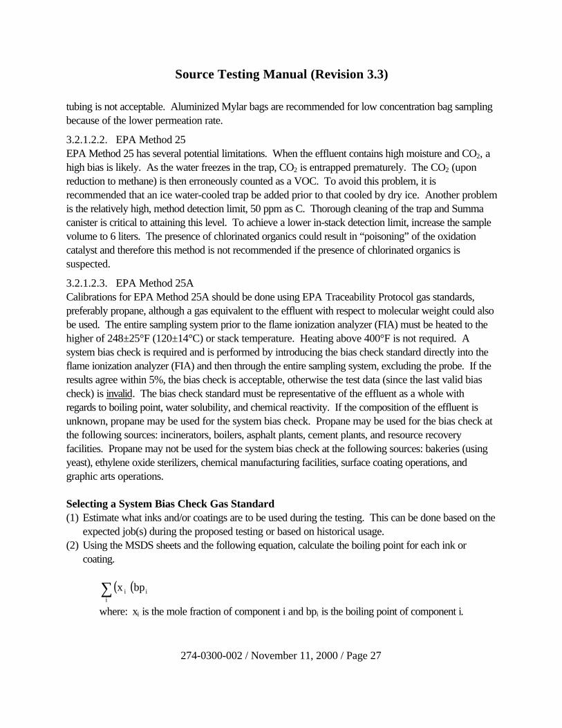
Selecting a System Bias Check Gas Standard(1) Estimate what inks and/or coatings are to be used during the testing. This can be done based on the
expected job(s) during the proposed testing or based on historical usage.(2) Using the MSDS sheets and the following equation, calculate the boiling point for each ink or
coating.
( )( )ii
i bpx∑where: xi is the mole fraction of component i and bpi is the boiling point of component i.

Source Testing Manual (Revision 3.3)
274-0300-002 / November 11, 2000 / Page 28
(3) Determine the relative solubility in water based on polarity and/or a reference (such as The MerckIndex).
(4) If >1 ink and/or coating is to be used, estimate the relative usage of each and determine the boilingpoint for the mixture of inks and/or coatings by (a) multiplying the relative usage by the boiling pointfor the ink or coating (from step 2 above) and (b) summing the values.
(5) The bias check gas should contain a component with a boiling point within 10% of the highestboiling point for any VOC in the ink and/or coating, a component with similar water solubility, and acomponent with similar reactivity. A two-component blend is necessary if the effluent containswater soluble VOCs and the highest boiling compound in the effluent is not water soluble (notpolar). The concentration of the bias check gas should be similar to the expected concentration atthe sampling location.
3.2.1.3. Reporting of EmissionsThe test report should clearly indicate how the emissions have been reported (ppmvd as propane, forexample). The pretest procedural protocol, if submitted, should also specify in detail how the emissionswill be reported. Strict conformance with the definitions in §1.3 of this manual is critical! TheDepartment requires all emissions to be reported in ppmvd (parts per million, by volume, dry basis) andlbs./hour as outlined in one of the following four scenarios. In the absence of data to prove otherwise,the Department will assume that the composition of the effluent before and after a control device is thesame. Subject to written approval by the Department, the emissions of TOC or TNMOC may bereported in lieu of reporting the VOC emissions.
(1) If a source is subject to a federal subpart (NSPS, NESHAPS, MACT, etc.) that specifies howto report the emissions, you must report the emissions in that manner. In addition, if a sourcewould be subject to a federal subpart, but because of it’s size, date of construction, or othersuch factors, is exempt, the testing and reporting should still comply with the requirements of thesubpart. Some of the source categories included under this scenario are bulk gasoline loadingterminals, landfills, and ethylene oxide sterilizers.
(2) If the VOC emissions are of an unknown, highly variable nature, the results shall be reported interms of propane. Some of the sources included in this category are: incinerators, boilers;asphalt plants, cement plants, and resource recovery facilities.
(3) If the composition of the effluent is known and a single VOC constitutes =75% (by volume) ofthe total emissions from a source, the emissions must be reported in terms of that compound.Some of the source categories included under this scenario are bakeries (using yeast) andsynthetic organic chemical manufacturing industry (SOCMI) facilities.
(4) If the composition of the effluent is known and a single VOC does not constitute =75% (byvolume) of the total emissions from a source, the emissions must be reported in terms of adepartment-approved surrogate. Anticipated chemical usage for the source(s) during each test

Source Testing Manual (Revision 3.3)
274-0300-002 / November 11, 2000 / Page 29
run should be used to select the surrogate. Some of the sources included in this category are:surface coating operations and graphic arts operations. As an alternative, if the primary intent ofthe testing is to determine the destruction efficiency of a control device, the results at both theinlet and the outlet should be reported as propane and the actual emissions (if needed) shouldbe determined using the following equation, or a modified version that has been approved by theDepartment prior to testing.
( )( )( )( ){ } ( )( )( ){ }CE1Content VOC UsageCoatingCEDE1Content VOC UsageCoatingRateEmission −+−=
Sample Calculationswhere:
RF: the response factor, as defined in §1.3.4.3 of this manualRRFC3H8: the response factor of propane divided by the number of carbon atoms in
propane.RRFC2H5OH: the response factor of ethanol divided by the number of carbon atoms in
ethanol.KM25A: the carbon equivalent correction factor from EPA Method 25A, Equation 25A-
1ppmvw: the parts of pollutant per million parts of air, by volume, on a wet basisMWC: the molecular weight of carbon, 12.01 lbs./lb.-moleMWC2H5OH: the molecular weight of ethanol, 46.07 lbs./lb.-moleBws: the proportion of water vapor, by volume, in the effluentQsd: the volumetric flow rate of the effluent in dscfh
Example 1Calculating the VOC mass emission rate from a source emitting mostly ethanol (C2H5OH) using EPAMethod 25A data in terms of propane…
( )( )( )
( )( ) hourOHHC lbs
RRFRRF
MWatoms C #
MW6385.3x10
)(QMWKB1
HC as ppmvw
52
OHHC
HC
COHHC
OHHCsdCM25A
ws
83
52
83
52
52 =
−
or

Source Testing Manual (Revision 3.3)
274-0300-002 / November 11, 2000 / Page 30
( ) ( )( )
( )( ) hourOHHC lbs
0.701.00
12.01246.07
6385.3x10
)(Q12.013B1
HC as ppmvw
52sd
ws
83
=
−
Example 2Calculating the VOC mass emission rate from a source emitting mostly ethanol (C2H5OH) using EPAMethod 25 data in terms of carbon…
( )( )
( )( ) hourOHHC lbs
MWatoms C #
MW6385.3x10
)(QMWB1
C as ppmvw
52
COHHC
OHHCsdC
ws
52
52 =
−
or
( )( )
( )( ) hourOHHC lbs
12.01246.07
6385.3x10
)(Q12.01B1
C as ppmvw
52sd
ws =
−
3.2.1.4. Capture Efficiency (CE)There are several reference methods for the determination of the capture efficiency of a control device:EPA Methods 204, 204A, 204B, 204C, 204D, 204E, and 204F. All capture efficiency testing mustbe conducted in accordance with the reference method and any additional (or more stringent)requirements in EMC Guideline Documents 035 and 036.
3.2.1.5. Coatings and Printing InksThe reference method for the determination of the volatile matter content, water content, density,volume solids, and weight solids of all surface coatings or inks excluding publication rotogravure inks isEPA Method 24. The reference method for the determination of volatile matter content and density ofpublication rotogravure inks is EPA Method 24A. Analysis of the aforementioned coatings may also beconducted in accordance with the following methods (when applicable).• ASTM D6053-96 (Standard Test Method for Determination of Volatile Organic Compound
(VOC) Content of Electrical Insulating Varnishes).• ASTM D2697-86 (1991) (Standard Test Method for Nonvolatile Matter in Clear or Pigmented
Coatings).• ASTM D6093-97 (Standard Test Method for Percent Volume Nonvolatile Matter in Clear or
Pigmented Coatings Using a Helium Gas Pycnometer).
Source Testing Manual (Revision 3.3)
274-0300-002 / November 11, 2000 / Page 31
• ASTM D3960-96 (Standard Practice for Determining Volatile Organic Compound Content ofPaints and Related Coatings).
• EPA SW-846 Methods 5030B and 8260B.
3.2.2. Total Organic Compounds (TOCs)There are several ways to determine the emissions of TOCs. Knowledge of the effluent compositionand expected concentrations (as C) are necessary to determine which test method to use. If the effluentis known to consist primarily of alkanes, alkenes, and arenes (aromatics) with concentrations of 1-100,000 ppm, EPA Method 25A, which utilizes a flame ionization analyzer (FIA), may be used. Forconcentrations in excess of 100,000 ppm, EPA Method 25B, utilizing a non-dispersive infrared analyzer(NDIR), is preferred. If the effluent contains organic compounds other than alkanes, alkenes, andarenes, EPA Method 25A is not applicable. For instance, at wood products mills or wood-firedsources, formaldehyde may be emitted. EPA SW-846 Method 0011, or an equivalent method, mustbe used to account for the emissions of formaldehyde. If the composition of the effluent is known andthere are only a few organic compounds, which can be easily separated by chromatography, EPAMethod 18 could be employed by quantifying all of the organic compounds and summing the individualemission rates.
Determination of TOC emissions from cold rolling mills should utilize Alcoa Methods 1470-94(Sampling Method for the Determination of Hydrocarbons Emissions from Cold Rolling Mills) and1471-94 (Analysis Method for Determination of Hydrocarbon Emissions from Aluminum Rolling Mills).The sample train consists of a cyclone for particulate or “oil mist” removal and a two-section charcoalsorbent tube for capture of the volatile fraction. Analysis is by gas chromatography with flame ionizationdetection (GC/FID). A copy of this method is available from the Department upon request.
3.2.3. Total Non-Methane Organic Compounds (TNMOCs)The reference method for the determination of the TNMOCs is EPA Method 25 that utilizes a gaschromatograph, oxidation and reduction catalysts and a flame ionization detector (GC/FID) for effluentwith concentrations of 50-100,000 ppm. EPA Method 25A may be utilized in conjunction with EPAMethod 18 for the determination of TNMOCs at concentrations <50 ppm as carbon. If this is done,the recovery study of the latter method is not required for methane. Alternatively, EPA Method 18 maybe used alone at sources emitting <10 organic compounds. EPA Method 25C is the preferred methodfor the determination of TNMOCs in landfill gas.
3.2.4. Semivolatile Organic Compounds (SVOCs)The reference method for the isokinetic collection of SVOCs is EPA SW-846 Method 0010. The trainutilizes an all glass or Teflon train with a heated filter, a condenser, and an XAD-2 sorbent trap. It iscritical that the trap be kept chilled to =68°F and wrapped in aluminum foil to prevent degradation of
Source Testing Manual (Revision 3.3)
274-0300-002 / November 11, 2000 / Page 32
the sample. Furthermore, the trap must not be packed in the field due to the certainty of crosscontamination. Analysis is by gas chromatography/mass spectrometry (GC/MS) per EPA SW-846Method 8270D.

Source Testing Manual (Revision 3.3)
274-0300-002 / November 11, 2000 / Page 33
3.2.5. Hazardous Air Pollutants (HAPs)
3.2.5.1. Aldehydes and KetonesThe reference method for the isokinetic collection of formaldehyde, acetaldehyde, acetophenone,isophorone, and propionaldehyde is EPA SW-846 Method 0011 which utilizes an aqueous solution of2,4-dinitrophenylhydrazine (2,4-DNPH) as a derivitizing agent to form the corresponding water-insoluble hydrazone. Analysis is by EPA SW-846 Method 8315A which utilizes high-pressure liquidchromatography and an UV detector (HPLC/UV). The possibility of extending the application of EPASW-846 Method 0011 to other aldehydes and/or ketones will be evaluated by the Department on acase-by-case basis. This method is not applicable to quinone, acrolein, methyl ethyl ketone, or methylisobutyl ketone. NCASI Method CI/WP-98.01 (Chilled Impinger Method for Use at Wood ProductsMills to Measure Formaldehyde, Methanol, and Phenol) is an acceptable alternative for the non-isokinetic determination of formaldehyde at rotary dryers, MDF dryers, urea-formaldehyde presses,and phenol-formaldehyde presses. NCASI Method CI/SG/PULP-94.02 (Chilled Impinger / Silica GelTube Test Method at Pulp Mill Sources for Methanol, Acetone, Acetaldehyde, Methyl Ethyl Ketone,and Formaldehyde) is an acceptable alternative for the non-isokinetic determination of formaldehyde atbrownstock washer hoods, bleach plant scrubbers, smelt dissolving tanks, and recovery furnaces.The reference methods for the determination of principal organic hazardous constituents are EPA SW-846 Methods 0030, 0031, and 0040.
3.2.5.2. Hydrogen Cyanide (HCN)Sampling for hydrogen cyanide utilizes an EPA Method 5-type train except that the impingers containsodium hydroxide (0.1N NaOH). The hydrogen cyanide is converted to cyanide ion (HCN? CN-)provided the pH=12. Following each sampling run or prior to the addition of OH-, the pH of thesolution in the first impinger must be checked and recorded. The pH should also be checked duringport changes. The pH must be maintained at =12 for the run to be valid. Analysis is by ionchromatography.
3.2.5.3. Polycyclic Organic Matter
3.2.5.3.1. Polychlorinated Dibenzo-p-Dioxins/Furans (PCDDs/PCDFs)The reference method for the isokinetic collection of the various PCDD and PCDF congeners is EPAMethod 23 that utilizes an XAD-2 sorbent trap. Recovery of the sampling train involves the use of anacetone/methylene chloride rinse followed by a toluene rinse. These rinses may be combined prior toanalysis. Furthermore, the methylene chloride rinse is optional. Analysis is by high-resolution gaschromatography and high-resolution mass spectrometry (HRGC/HRMS) as detailed in EPA SW-846Method 8290A. Use of low-resolution mass spectrometry (EPA SW-846 Method 8280B) is notpermitted unless the detection limit requirements (§2.2) of this manual are met.
Source Testing Manual (Revision 3.3)
274-0300-002 / November 11, 2000 / Page 34
3.2.5.3.2. Polychlorinated Biphenyls (PCBs)The reference method for the isokinetic collection and recovery of PCBs is EPA SW-846 Method0010. Analysis is performed by California Air Resources Board (CARB) Method 428 that utilizeshigh-resolution gas chromatography and high-resolution mass spectrometry (HRGC/HRMS).
3.2.5.3.3. Polycyclic Aromatic Hydrocarbons (PAHs)The reference method for the isokinetic collection and recovery of polycyclic aromatic hydrocarbons isEPA SW-846 Method 0010. Analysis is performed by EPA SW-846 Method 8270D that utilizes gaschromatography and low-resolution mass spectrometry (GC/LRMS). A high-resolution massspectrometry technique is under development and upon validation it should be used instead of EPASW-846 Method 8270D unless the detection limit requirements (§2.2) of this manual are met withLRMS.
3.3. Visible Emissions (Opacity)The standard reference methods for the determination of visible emissions are EPA Methods 9 andAlternative Method 1 (9A; lidar). Method 9 is preferred (when applicable). Opacity observations atcoke oven batteries shall be conducted in accordance with the procedures in EPA Method 303 or303A.
3.4. Fuel Samples
3.4.1. General Collection Criteria
3.4.1.1. The sample acquisition point(s) must be located as close to the point at which the fuel isburned and as far downstream of any process(es) which could alter the quality of the fuel(prior to combustion), as possible.
3.4.1.2. A sample should be collected from each fuel-input stream, unless sampling at one locationwill yield representative results.
3.4.1.3. Sampling should be conducted at a given location without discrimination based on theappearance of the material.
3.4.1.4. Samples should be collected from each location at intervals not to exceed 30 minutes.
3.4.1.5. Samples for a source collected over the period of one test run should be combined andanalyzed as a single sample.
3.4.2. Fuel Specific CriteriaFuel analysis may be necessary to determine emission rates in terms of the heat input to the source. Theheat input can be determined from the gross calorific value of the fuel and an ultimate analysis. Results

Source Testing Manual (Revision 3.3)
274-0300-002 / November 11, 2000 / Page 35
must be reported on an “as received” basis. Any equivalent ASTM Method may be used in lieu of themethods specified in this section.
3.4.2.1. Coal and Coke
3.4.2.1.1. CollectionCoal samples must be collected in accordance with ASTM Method D 2234-96 (Standard Practice forCollection of a Gross Sample of Coal). Prior to analysis, the coal samples shall be prepared inaccordance with ASTM Method D 2013-86 (Standard Method of Preparing Coal Samples forAnalysis). Coke samples shall be collected and prepared for analysis in accordance with ASTMMethod D 346-90 (Practice for Collection and Preparation of Coke Samples for Laboratory Analysis).The recommended size for a composite sample is 1 gallon.
3.4.2.1.2. Analysis
3.4.2.1.2.1. Gross Calorific Value (GCV)The GCV (Btu/lb.) shall be determined in accordance with ASTM Method D 2015-96 (Standard TestMethod for Gross Calorific Value of Coal and Coke by the Adiabatic Bomb Calorimeter), ASTMMethod D 1989-97 (Standard Test Method for Gross Calorific Value of Coal and Coke byMicroprocessor Controlled Isoperibol Calorimeters), or ASTM Method D 3286-96 (Standard TestMethod for Gross Calorific Value of Coal and Coke by Isoperibol Bomb Calorimeter).
3.4.2.1.2.2. Carbon and Hydrogen ContentThe carbon and hydrogen content shall be determined in accordance with ASTM Method D 3178-89(1993) (Standard Test Methods for Carbon and Hydrogen in the Analysis Sample of Coal and Coke)or ASTM Method D 5373-93 (1997) (Instrumental Determination of Carbon, Hydrogen, and Nitrogenin Laboratory Samples of Coal and Coke).
3.4.2.1.2.3. Sulfur ContentThe sulfur content shall be determined in accordance with ASTM Method D 3177-89 (Standard TestMethods for Total Sulfur in the Analysis Sample of Coal and Coke) or D 4239-97 (Standard TestMethod for Sulfur in the Analysis Sample of Coal and Coke Using High Temperature Tube FurnaceMethods).
3.4.2.1.2.4. Nitrogen ContentThe nitrogen content shall be determined in accordance with ASTM Method D 3179-89 (1993)(Standard Test Methods for Nitrogen in the Analysis Sample of Coal and Coke) or ASTM Method D5373-93 (1997) (Instrumental Determination of Carbon, Hydrogen, and Nitrogen in LaboratorySamples of Coal and Coke).
3.4.2.1.2.5. Ash ContentThe percent ash shall be determined in accordance with ASTM Method D 3174-97 (Standard TestMethod for Ash in the Analysis Sample of Coal and Coke from Coal) or ASTM Method D 5142-90

Source Testing Manual (Revision 3.3)
274-0300-002 / November 11, 2000 / Page 36
(1994) (Standard Test Method for the Proximate Analysis of the Analysis Sample of Coal and Coke byInstrumental Procedures). When using the latter method, the instrumental results must be corrected orthe instrument must be calibrated using samples of known proximate analysis, as discussed in §1(Scope) of the method. ASTM Method D 5142-90 (1994) is “not applicable to thermogravimetricanalyzers (TGA) utilizing microgram size samples”.
3.4.2.1.2.6. Oxygen ContentThe percent oxygen shall be determined by difference per the following equation:%O = 100 - (%C) - (%H) - (%S) - (%N) - (%Ash).
3.4.2.1.2.7. Moisture ContentThe percent moisture shall be determined in accordance with ASTM Method D 3173-87 (1996)(Standard Test Method for Moisture in the Analysis Sample of Coal and Coke), ASTM Method D5142-90 (1994) (Standard Test Method for the Proximate Analysis of the Analysis Sample of Coal andCoke by Instrumental Procedures), or ASTM Method D 2961-95a. When using ASTM Method D5142-90 (1994), the instrumental results must be corrected or the instrument must be calibrated usingsamples of known proximate analysis, as discussed in §1 (Scope) of the method. ASTM Method D5142-90 (1994) is “not applicable to thermogravimetric analyzers (TGA) utilizing microgram sizesamples”. Material subjected to ASTM Method D 2961-95a may not be used in the determination ofother parameters.
3.4.2.2. Fuel Oil
3.4.2.2.1. CollectionFuel oil samples must be collected in accordance with ASTM Method D 4057-95 (Standard Practicefor Manual Sampling of Petroleum and Petroleum Products) or ASTM Method D 4177-95 (StandardPractice for Automatic Sampling of Petroleum and Petroleum Products).
3.4.2.2.2. Analysis
3.4.2.2.2.1. Sulfur ContentThe following ASTM methods are acceptable for the determination of the sulfur content: D 129-95(Standard Test Methods for Sulfur in Petroleum Products: General Bomb Method), D 1266-91(Standard Test Methods for Sulfur in Petroleum Products: Lamp Method), D 1552-95 (Standard TestMethods for Sulfur in Petroleum Products: High-Temperature Method), or D 2622-94 (Standard TestMethods for Sulfur in Petroleum Products by X-Ray Spectrometry).
3.4.2.3. Wood
3.4.2.3.1. CollectionWood samples must be collected in accordance with the procedures specified in §6.1 of ASTMMethod E 871-82 (1987).

Source Testing Manual (Revision 3.3)
274-0300-002 / November 11, 2000 / Page 37
3.4.2.3.2. Analysis
3.4.2.3.2.1. Gross Calorific Value (GCV)The GCV (Btu/lb.) shall be determined in accordance with ASTM Method E 711-87 (Standard TestMethod for Gross Calorific Value of Refuse-Derived Fuel by the Bomb Calorimeter).
3.4.2.3.2.2. Carbon and Hydrogen ContentThe carbon and hydrogen content shall be determined in accordance with ASTM Method E 777-87(1992) (Standard Test Method for Carbon and Hydrogen in the Analysis Sample of Refuse-DerivedFuel).
3.4.2.3.2.3. Sulfur ContentThe sulfur content shall be determined in accordance with ASTM Method E 775-87 (Standard TestMethods for Total Sulfur in the Analysis Sample of Refuse-Derived Fuel).
3.4.2.3.2.4. Nitrogen ContentThe nitrogen content shall be determined in accordance with ASTM Method E 778-87 (1992)(Standard Test Methods for Nitrogen in the Analysis Sample of Refuse-Derived Fuel).
3.4.2.3.2.5. Ash ContentThe percent ash shall be determined in accordance with ASTM Method D 1102-84 (1995) (StandardTest Method for Ash in Wood).
3.4.2.3.2.6. Oxygen ContentThe percent oxygen shall be determined by difference per the following equation:%O = 100 - (%C) - (%H) - (%S) - (%N) - (%Ash).
3.4.2.3.2.7. Moisture ContentThe percent moisture shall be determined in accordance with ASTM Method E 871-82 (1987)(Standard Method for Moisture Analysis of Particulate Wood Fuels).
3.4.2.4. Refuse-Derived Fuel (RDF)
3.4.2.4.1. CollectionRDF samples must be collected in accordance with ASTM Method D 5115-90 (Standard TestMethod for Collecting Gross Samples and Determining Fuel Quality of RDF. Prior to analysis, thesample(s) shall be prepared in accordance with ASTM Method E 829-94 (Standard Practice forPreparing Refuse-Derived Fuel (RDF) Laboratory Samples for Analysis).
3.4.2.4.2. Analysis
3.4.2.4.2.1. Gross Calorific Value (GCV)The GCV (Btu/lb.) shall be determined in accordance with ASTM Method E 711-87 (Standard TestMethod for Gross Calorific Value of Refuse-Derived Fuel by the Bomb Calorimeter).

Source Testing Manual (Revision 3.3)
274-0300-002 / November 11, 2000 / Page 38
3.4.2.4.2.2. Carbon and Hydrogen ContentThe percent carbon and hydrogen shall be determined in accordance with ASTM Method E 777-87(1992) (Standard Test Method for Carbon and Hydrogen in the Analysis Sample of Refuse-DerivedFuel).

Source Testing Manual (Revision 3.3)
274-0300-002 / November 11, 2000 / Page 39
3.4.2.4.2.3. Sulfur ContentThe percent sulfur shall be determined in accordance with ASTM Method E 775-87 (Standard TestMethods for Total Sulfur in the Analysis Sample of Refuse-Derived Fuel).
3.4.2.4.2.4. Nitrogen ContentThe percent nitrogen shall be determined in accordance with ASTM Method E 778-87 (1992)(Standard Test Methods for Nitrogen in the Analysis Sample of Refuse-Derived Fuel).
3.4.2.4.2.5. Ash ContentThe percent ash shall be determined in accordance with ASTM Method D 830-87 (Standard TestMethod for Ash in the Analysis Sample of Refuse-Derived Fuel).
3.4.2.4.2.6. Oxygen ContentThe percent oxygen shall be determined by difference per the following equation:%O = 100 - (%C) - (%H) - (%S) - (%N) - (%Ash).
3.4.2.4.2.7. Moisture ContentThe percent moisture shall be determined in accordance with ASTM Method E 790-87 (1996)(Standard Test Method for Residual Moisture in a Refuse-Derived Fuel Analysis Sample).
4. ReferencesAmerican Society for Testing and Materials. Annual Book of ASTM Standards. 1998.National Council of the Paper Industry for Air and Stream Improvement, Inc. Chilled Impinger / Silica
Gel Tube Test Method at Pulp Mill Sources for Methanol, Acetone, Acetaldehyde, MethylEthyl Ketone, and Formaldehyde. Method CI/SG/Pulp-94.02. August 1998.
National Council of the Paper Industry for Air and Stream Improvement, Inc. Chilled Impinger Methodfor Use at Wood Products Mills to Measure Formaldehyde, Methanol, and Phenol. MethodCI/WP-98.01. August 1998.
National Council of the Paper Industry for Air and Stream Improvement, Inc. Determination ofChlorine and Chlorine Dioxide in Pulp Mill Bleach Plant Vents. Proposed Method. August1997.
National Council of the Paper Industry for Air and Stream Improvement, Inc. Determination of SulfuricAcid Vapor or Mist and Sulfur Dioxide Emissions from Kraft Recovery Furnaces. Method 8A.December 1996.
National Council of the Paper Industry for Air and Stream Improvement, Inc. Measurement andQuality Assurance Procedures for Determining Chloroform, Chlorine, and Chlorine DioxideReleases from Pulp Bleach Plants. Special Report 91-07. June 1991.
National Council of the Paper Industry for Air and Stream Improvement, Inc. Iodometric Analysis ofChlorine and Chlorine Dioxide in the Presence of Hydrogen Peroxide. Special Report 95-06.April 1995.

Source Testing Manual (Revision 3.3)
274-0300-002 / November 11, 2000 / Page 40
National Council of the Paper Industry for Air and Stream Improvement, Inc. Optimization andEvaluation of an Impinger Capture Method for Measuring Chlorine and Chlorine Dioxide inPulp Bleach Plant Vents. Technical Bulletin 520. April 1987.
Pennsylvania Code. Title 25. Chapters 121-143 (Air Resources).Pennsylvania Department of Environmental Protection. Pollution Prevention Guide for Bureau of Air
Quality, Division of Source Testing and Monitoring. September 1997.Shigehara, R.T., R.M. Neulicht, W.S. Smith, and J.W. Peeler. Summary of F-Factor Methods for
Determining Emissions from Combustion Sources. Source Evaluation Society Newsletter.1(4). November 1976.
Triangle Laboratories, Inc. Proposed New EPA Field and Lab Test Methods. The Riley Report.1(1). September 1995.
Triangle Laboratories, Inc. Dioxin/Furan Test Methods Confusion. The Riley Report. 1(2).December 1995.
Triangle Laboratories, Inc. Insight into EPA’s Test Methods for Hydrogen Chloride (HCl) andChlorine (Cl2). The Riley Report. 2(1). April 1996.
Triangle Laboratories, Inc. Measurement of Trace Metals; Especially Mercury. The Riley Report.2(2). October 1996.
Triangle Laboratories, Inc. Measurement of Total Organics. The Riley Report. 3(1). February 1997.United States Code of Federal Regulations. Title 40. Part 51 (Appendix M). July 1999.United States Code of Federal Regulations. Title 40. Part 60 (Appendix A). July 1999.United States Code of Federal Regulations. Title 40. Part 61 (Appendix B). July 1999.United States Code of Federal Regulations. Title 40. Part 63 (Appendix A). July 1999.United States Code of Federal Regulations. Title 40. Part 80 (Appendix D). July 1999.United States Code of Federal Regulations. Title 40. Part 80 (Appendix E). July 1999.United States Code of Federal Regulations. Title 40. Part 266 (Appendix IX). July 1999.Unites States Environmental Protection Agency. Test Methods for Evaluating Solid Waste
Physical/Chemical Methods. EPA SW-846, 3rd Edition. November 1996. (as amended byDraft Update IVA, January 1998).
Unites States Environmental Protection Agency. Quality Assurance Handbook for Air PollutionMeasurement Systems. Volume III: Stationary Source Specific Methods. EPA-600/4-77-027b. February 1993.
Unites States Environmental Protection Agency. EPA Traceability Protocol for Assay and Certificationof Gaseous Calibration Standards. RTI/6960/208-01F. September 1993.