source of electromotive force a device that, by doing work on charge carriers, maintains a potential...
TRANSCRIPT

source of electromotive force
A device that, by doing work on charge carriers, maintains a potential difference between its terminals is called a source of electromotive force (emf).
Other form of energy is converted into electricity in a source of electromotive force:
battery - chemical energyelectric generator - mechanical energysolar cell - electromagnetic radiationthermopile - internal energyliving cell - chemical energy

electromotive force
The maximum electric potential difference that can exist between the terminals of the voltage source is called the electromotive force of that source.
I
r+ - IrVV
Voltage produced by a real source of electromotive force:

direct and alternating current
If the charge moves in a circuit in the same direction at all times, the current is said to be direct current (DC). Constant current (independent of time) is a special case of direct current.
If the charges move (across a surface) changing their direction of motion, the current is said to be alternating current (AC).
+
+++
+
+ +
++
+++
+
+ +
++
+++
+
+ +
++
+++
+
+ +
++
+++
+
+ +
++
+++
+
+ +
+
+
+ ++
+
++
++
+ ++
+
++
++
+ ++
+
++
+
+
+++
+
+ +
++
+++
+
+ +
++
+++
+
+ +
+
+
+ ++
+
++
++
+ ++
+
++
++
+ ++
+
++
+
+
+++
+
+ +
++
+++
+
+ +
++
+++
+
+ +
+

circuit analysis Kirchhoff's Junction Rule:
The sum of all the currents entering a junction is zero.
Kirchhoff's Loop Rule:Around any closed circuit loop
the sum of potential differences is zero.
I1
I2
In
i
i 0I V1
V2
Vn
i
i 0V

electrical measurements Current is measured with an ammeter, which must be inserted into the circuit in series with the element in which the current is measured.
Voltage is measured with a voltmeter, which must be inserted into the circuit in parallel to the elements across which the voltage is measured.
The resistance of passive elements can be measured with an ohmmeter.
V
+
-
A
V
?

electric current & the human body
Currents of 200 mA can be fatal. A current that strong can affect the proper operation of the heart.
A current above 100 mA can cause muscle spasm.
A person can sense an AC with a current of 1mA.
NEVER TOUCH AN OPERATING CIRCUIT WITH BOTH HANDS !!!

inductors
An inductor is an element of a circuit with two sides for which (at any instant) the potential difference V between its terminals is proportional to the rate of change in current I passing through this element.
I
VaVb dt
dILVV ba
The proportionality coefficient L is called the inductance of the inductor.
In SI the henry is the unit of inductance HVsA

sinusoidal alternating current
For a sinusoidal alternating current, both the voltage V(t) across an element and the current I(t) through this element are sinusoidal functions of time.
V t V tm v( ) sin( )
I t I tm I( ) sin( )
Va(t) Vb(t)
I (t)
Vm, Im - the peak value
(t+) - the phase
= 2f - the angular frequency
- the initial phase
t
VI

electric power
t
V
I
P
tVtI)t(P
Electric power delivered to an electrical element is a sinusoidal function of time.
)tsin()tsin(VI VImm
VIIVmm t2coscosVI2
1
cosVIP rmsrmsav
Pav
where IV
21
av2
rms tff

AC in the US standard one phase power line
The voltage oscillates with frequency f = 60 Hz.
0 V
0 V
0 V
120 V
“ground”
“zero”“hot”
breaker

AC in the US three phase power line
The rms voltage between any "hot" wire and the zero wire is 127 V.
Three "hot" wires with phases differing by , the "zero" and the "ground" wires are connected to the outlet.
3
2
The voltage between any two "hot" wires is 220 V.
t
V

complex voltage
The complex function V(t) such that the voltage across the element is
V(t) = Im V(t) is called the complex voltage.
Sinusoidal voltage: V V0t V e e emi i t i tV
tIm V VVm tsinitcosVIm Vm tsinV tV
t
VIm V
Re V
V (t)Vm
t
-Vm
t+V

complex current
The complex function I(t) such that the current through the element is
I(t) = Im I(t) is called the complex current.
Sinusoidal current: titiim eeeIt V 0II
tImI VVm tsinitcosIIm Vm tsinI tI
t
IIm I
Re I
I (t)Im
t+I
t
-Im

relation between voltage and current
The coefficient Z relating the peak values of the voltage across the system with the peak value of the current through the system is called the impedance of the system.
Vm = Im·ZIV
Vm
Im
t
note that: Vrms = Irms·Z
The number relating the phase of the voltage across the system with the phase of the current through the system is called the phase angle between the current and the voltage
IV tt
and V = I +

i
m
m eI
V
Z
complex impedance
The complex coefficient Z, relating the complex voltage across an element with the complex current through this element, is called the complex impedance of this element at frequency :
Im
Re
V I ZIV tt
Complex impedance Z includes information about both the impedance Z as well as about the phase angle
Z
ZZZ Z
Re
Imtan
tiim eeV VV IZ
ZIV tt ZIV ,0,0
tiim eeI I

AC in a resistor
R
a
b
Ireal analysis
tI Itsin mI RIm RtV
0 RZR ,
impedance and phase angle
average power:
t
V
I
0cosVIP rmsrmsav
RI2rms
R
V2rms
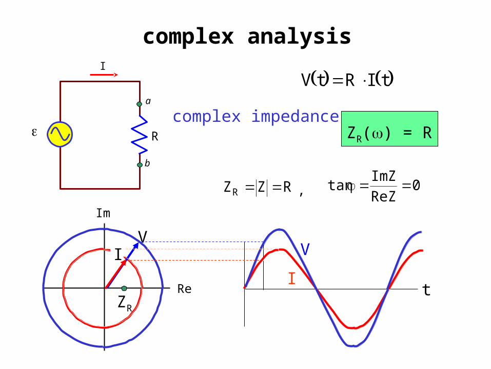
AC in a resistorcomplex analysis
R
a
b
I
IRV
0Re
Imtan
ZZ
RZR Z ,
complex impedance
tIm V tRIm I tRt IV
ZR() = R
t
V
I
Im
ReZR
VI

L
a
b
I
AC in an inductorreal analysis
tI Im tsinI dt
dLtV
2
LZL ,
impedance and phase angle
average power:
t
VI0
2cosVIP rmsrmsav
dt
dL =
Im tcosIL
2
tsinIL Im

L
a
b
I
complex analysis
t
VI
dt
dILV tIm V
dt
dLIm
I dt
dLt
IV tie
dt
dL 0I tLi I
complex impedanceZL() = iL
Im
Re
ZLI
V
ZZ
Re
ImtanLZL Z ,

AC in an capacitorreal analysis
Vm tsinVtV
2
C
1ZC
,
impedance and phase angle
average power:
t02
cosVIP rmsrmsav
Vm tcosVC
2
tsinCV Vm
VI
C
a
b
I
Q
-Q
CtQ dt
dtI