source four - prisma-scene · source four assembly guide 9 28 27 20 figure 10 15. using the four...
TRANSCRIPT

Assembly GuideSource Four™

2 Electronic Theatre Controls, Inc.

Source Four Assembly Guide 3
Table of Contents
Final assembly .............................................................................. 5
Lamp socket assembly ................................................................. 6
Reflector housing assembly ........................................................ 10
To remove a reflector ............................................................ 11
To install a reflector ............................................................... 11
To clean the reflector ............................................................ 11
Front barrel assembly ................................................................. 13
19º, 26º, 36º, and 50º lens tube assembly .................................. 15
Cleaning 19º, 26º, 36º, and 50º glass lenses ............................... 16
5º and 10º lens tube assembly .................................................... 19
Cleaning 5º and 10º polymer lenses ............................................ 19

4 Electronic Theatre Controls, Inc.

Source Four Assembly Guide 5
Final assembly
Reference Part Description QuantityNumber Number Required
1 7060A2008 Lamp socket assembly 12 7060A2011 Rear housing assembly, single clutch 12A 7060A2020 Rear housing assembly, double clutch 13 7060A2012 Front barrel assembly 14 7060A2000-K 5° lens tube, with knob (See page 14) 15 7060A2001-K 10° lens tube, with knob (See page 13) 16 7060A2002-K 19° lens tube (6 x 16), with knob 17 7060A2003-K 26° lens tube (6 x 12), with knob 18 7060A2004-K 36° lens tube (6 x 9), with knob 19 7060A2005-K 50° lens tube (4.5 x 6), with knob 1
10 7060A4008-01 Knob set with male insert 211 HW5143 Washer, flat fiber 1
Optional equipment12 HW5197 Screw, 1/4-20 x 5/8, black zinc 1
3
1
22A
11
10(2 required)
456789
12
10
Figure 1
6 Electronic Theatre Controls, Inc.
20
6
1
24 23
17
18(2 required)
13
4
15
16
3
5
2
21
11
24
9
8
7
10(2 required)
12
14
19
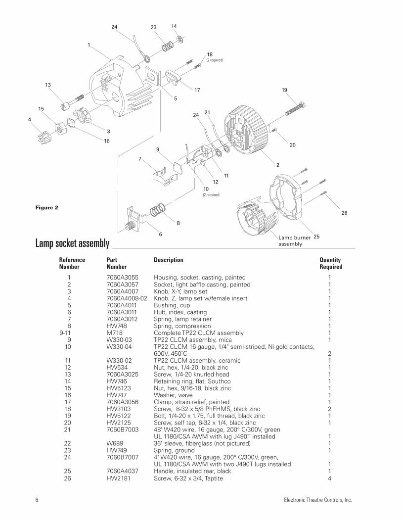
Lamp socket assemblyReference Part Description QuantityNumber Number Required
1 7060A3055 Housing, socket, casting, painted 12 7060A3057 Socket, light baffle casting, painted 13 7060A4007 Knob, X-Y, lamp set 14 7060A4008-02 Knob, Z, lamp set w/female insert 15 7060A4011 Bushing, cup 16 7060A3011 Hub, index, casting 17 7060A3012 Spring, lamp retainer 18 HW748 Spring, compression 1
9-11 M718 Complete TP22 CLCM assembly 19 W330-03 TP22 CLCM assembly, mica 1
10 W330-04 TP22 CLCM 16-gauge, 1/4" semi-striped, Ni-gold contacts,600V, 450˚C 2
11 W330-02 TP22 CLCM assembly, ceramic 112 HW534 Nut, hex, 1/4-20, black zinc 113 7060A3025 Screw, 1/4-20 knurled head 114 HW746 Retaining ring, flat, Southco 115 HW5123 Nut, hex, 9/16-18, black zinc 116 HW747 Washer, wave 117 7060A3056 Clamp, strain relief, painted 118 HW3103 Screw, 8-32 x 5/8 PhFHMS, black zinc 219 HW5122 Bolt, 1/4-20 x 1.75, full thread, black zinc 120 HW2125 Screw, self tap, 6-32 x 1/4, black zinc 121 7060B7003 48" W420 wire, 16 gauge, 200° C/300V, green
UL 1180/CSA AWM with lug J490T installed 122 W689 36" sleeve, fiberglass (not pictured) 123 HW749 Spring, ground 124 7060B7007 4" W420 wire, 16 gauge, 200° C/300V, green,
UL 1180/CSA AWM with two J490T lugs installed 125 7060A4037 Handle, insulated rear, black 126 HW2181 Screw, 6-32 x 3/4, Taptite 4
25
26
Lamp burnerassembly
Figure 2

Source Four Assembly Guide 7
Lamp socket assemblyTools required: Open-end adjustable wrench or a 7/16" socket,needle-nose pliers, screwdriver.
1. Install the screw (20) into the light socket baffle casting asshown in figure 3. (Also see figure 10 on page 9.)
Note: Do not install the screw if the fixture will be used with77V lamps and ETC’s Dimmer Doubler. This screw prevents 77Vlamps from being installed.
2. Insert the bolt (19) through the light baffle socket casting (2).
3. Install the green ground wire assemblies (21 and 24) on the bolt(19) with the prongs on the crimped connectors toward thecasting. Run both wires through the indent in the lip around thebolt hole. Secure with nut (12) and torque to 60 inch pounds.
4. Place the ceramic TP22 socket (11) into the light baffle socketcasting (2) as shown in figure 6. Be sure it is well seated. Firmlypush the connectors on the white TP22 leads (10) into thegrooves in the socket.
5. Place the TP22 mica (9) over the leads, then install the lampretainer spring (7). The lamp retainer spring secures the mica.Insert the spring one end at a time, making sure the rectangularslot in each side of the spring seats on the corresponding tab inthe casting.
Important: If the spring does not seat correctly, coax it intoplace with a screwdriver or needle-nose pliers.
6. Install the bushing cup (5) into the housing socket casting (1) asshown in figure 5. The cup should slide smoothly up and down,but not side to side.
7. Insert the threaded end of the index hub (6) through the holes inthe bushing cup and the back of the housing socket casting (1).
8. Slide the X-Y knob (3) over the exposed index hub bolt (6), theninsert the wave washer (16) on the bolt and secure with the 9/16hex nut (15). Hand tighten the X-Y knob (3).
Note: Install the wave washer with the upward curve towardthe hex nut.
9. Lay the leads in the bottom half of the cable clamp, making surethat the fiberglass sleeving extends slightly past the screw holesin the housing socket casting, (install new sleeving if necessary)
12
21
19
24
20
Figure 3
10
11
97
Figure 4
16
4
3
5
15
6
Figure 5
2
2
1
8 Electronic Theatre Controls, Inc.
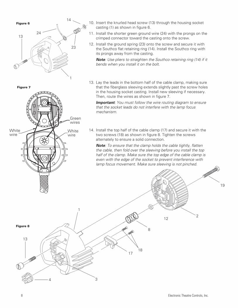
10. Insert the knurled head screw (13) through the housing socketcasting (1) as shown in figure 6.
11. Install the shorter green ground wire (24) with the prongs on thecrimped connector toward the casting onto the screw.
12. Install the ground spring (23) onto the screw and secure it withthe Southco flat retaining ring (14). Install the Southco ring withits prongs away from the casting.
Note: Use pliers to straighten the Southco retaining ring (14) if itbends when you install it on the bolt.
13. Lay the leads in the bottom half of the cable clamp, making surethat the fiberglass sleeving extends slightly past the screw holesin the housing socket casting. Install new sleeving if necessary.Then, route the wires as shown in figure 7.
Important: You must follow the wire routing diagram to ensurethat the socket leads do not interfere with the lamp focusmechanism.
14. Install the top half of the cable clamp (17) and secure it with thetwo screws (18) as shown in figure 8. Tighten the screwsalternately to ensure a solid connection.
Note: To ensure that the clamp holds the cable tightly, flattenthe cable, then fold over the sleeving before you install the tophalf of the clamp. Make sure the top edge of the cable clamp iseven with the edge of the socket to prevent interference withlamp focus movement. Make sure sleeving is not pinched.
Whitewire
Greenwires
Whitewire
14
23
1324
4
1
13
Figure 6
Figure 8
Figure 7
1
3
17
8
122
19
18

Source Four Assembly Guide 9
2827
20
Figure 10
15. Using the four screws (25), attach the handle (26) to the lampsocket assembly. See figure 9.
16. Place the spring (8) on the protrusion on the inside of the indexhub (6).
17. Insert bolt (19) through the light socket baffle (2), thread nut(12), through spring (8) and through the index hub (6) of thehousing socket (1), joining the two castings. Make sure wiresare not pinched between the two pieces.
18. Before proceeding, check again to make sure the wires are stillpositioned as indicated in figure 7. Adjust if necessary.
19. Press the two castings together firmly so the bottom of the lightbaffle (2) sits on top of the cable clamp (17), then install the X-Ylampset (3) and Z lamp knob (4). Hand tighten the knob all theway to the right.
Important: You must install Z knob as described above toensure proper lamp focus travel.
20. Set the crossbar of the retainer clip (27) under the two hooks onthe clip bracket as shown in figure 10.
21. Place the Tinnerman clip (28) over the retainer clip crossbarbetween the two hooks and press it down firmly until it snapsinto place.
25
26
Lamp socket assembly
Figure 9

10 Electronic Theatre Controls, Inc.
Reflector housing assembly
Reference Part Description QuantityNumber Number Required
1 7060A3054 Housing, reflector casting, painted black 12 7060A3006 Clip, reflector retainer 43 7060A4010 Bushing, gate 44 7060A3016 Plate, clutch 15 7060A3019 Spring, reflector support 16 7060A4015 Reflector, molded glass, coated 17 7060A3058 Bracket, yoke, painted 18 HW8144 Handle, yoke knob, 5/16 - 18 29 HW753 Rivet, machine, 3/16 x .720, flat head, black zinc 2
10 HW5126 Washer, flat, 5/16, black zinc 411 HW372 Screw, 8-32X1/4, PHPHMS B/Z 212 HW5125 Bolt, carriage, 5/16-18 x .75, black zinc 213 HW752 Rivet machine, 3/16 x 5/16, black zinc 4
Optional equipment
HW5127 Nut, hex 5/16-18 (can be used with (11) hex bolt)
1
10(3 required)
11(2 required)
9(2 required)
4
8
5
3(4 required)
12
7
6
2 (4 required)
13 (4 required)
Figure 11
Double-clutch reflector housing for 5°
and 10° fixtures.

Source Four Assembly Guide 11
To remove a reflectorTools required: Two spare reflector retainer clips (2).
1. Wedge one arm of a spare retainer clip between the lip of one ofthe installed clips and the rim of the reflector, then slide the armdown between the installed clip and the reflector as shown infigure 12.
2. Insert the other arm of the spare clip between the other arm ofthe installed clip and the reflector, as shown in figure 13.
Warning: Do not slide the spare clip all the way in or it will bevery difficult to remove…leave at least a quarter inch exposed.
3. Now slide the entire clip between the reflector and the installedclip as shown in figure 14. Remember, do not slide it all the wayin.
4. Repeat this procedure with the second spare clip, inserting itbetween an adjacent installed clip and the reflector.
5. Turn the reflector housing casting over, so that the rear of thereflector is in view. Gently push on the reflector, toward the sideof the housing where the extra clips were placed. The reflectorwill slip off to the side at an angle.
6. Turn the reflector housing casting back over and gently slide thereflector out from under the retaining clips.
To install a reflectorNote: The following assumes all four reflector retainer clips (2) havealready been riveted to the reflector housing casting (1) and the gatebushings (3) installed on the retainer clips.
1. Place the reflector housing casting (1) on a flat work surfacewith the large opening facing up.
2. Install the reflector support spring (5) in the circular opening atthe base of the casting.
3. Insert the reflector (6) at an angle, under any three legs of thereflector's clips.
4. Gently press down on the reflector until it snaps into place underthe clips.
Note: If the reflector does not snap in, turn the casting over.Gently pull on the side of the reflector that has not snapped inuntil the rest of the reflector slides into place.
To clean the reflectorRemove dust with a blast of oil-free air or wipe with a clean, lint-freecloth using alcohol or distilled water (alcohol is recommended).
Warning: Do not use glass and window cleaners on the reflector.Chemicals in these cleaners will stain the reflector.
Figure 13
Figure 12
Figure 14

12 Electronic Theatre Controls, Inc.
Front barrel assembly
Reference Part Description QuantityNumber Number Required
1 7060A3052 Front barrel, top casting, painted 12 7060A3053 Front barrel, bottom casting, painted 13 7060A2025 Shutter blade assembly, 22 gauge 44 7060A3001-01 Plate, divider with dimples (bottom) 25 7060A3003 Plate, gate (middle) 16 7060A3001-02 Plate, divider (top) 17 HW754 Shutter spring 48 HW370 Nut, Ny-lok, 8/32, black zinc 49 HW3154 Screw, 8/32 x 5/8, Taptite 4
10 7060A3045 Cover, iris slot 111 HW232 Screw, 6-32 x 1/4, black zinc 2
Note: The bottom divider plate (4)has four dimples punched into thesurface; the top plate (6) has none.The middle divider plates (5) arenoticeably thinner-gauge metalthan the other two.
(See detail to the right)
4
7(4 required)
2
8(4 required)
9(4 required)
1011(2 required)
1
3456
3
5
6
Figure 15
Figure 16

Source Four Assembly Guide 13
Front barrel assemblyTools required: Phillips head screwdriver.
1. Stand the top and bottom front barrel castings (1 and 2) uprightwith the shutter openings down.
Note: The top front barrel casting contains the iris slot.
2. Slide in the bottom divider plate (4). The dimples on the dividerplate must point down.
Note: The notches on the divider plates must fit snugly againstthe flanges in the casting so the plates do not move.
Warning: Divider plate edges are sharp. Handle with caution!
3. With the bottom barrel to your left, place two shutter blades (3)on top of dimple plate (4), handles facing outward, up and down.
Note: Install shutter blades with the rounded side facing uptoward the front of the casting.
4. Place a divider plate (5) on top of the two shutter blades.
5. Place another shutter blade on top of the middle divider plates.Then place another divider plate on top.
6. Place the fourth shutter blade on top of the divider. Pull theblade and plate assembly slightly forward to allow the handle toslip through the slot in the bottom casting.
7. Place the top divider plate (6) on top of the fourth shutter blade.
Note: Make sure no shutter assembly components are underthe pattern holder guides.
8. With both front barrel castings still standing upright, join the twohalves, sliding the handle of the top shutter blade through theslot in the top front barrel casting (1).
9. Starting at the bottom of the castings (closest to the shutters),use four PHMS screws (9) and Ny-lok nuts (8) to fasten the frontbarrel casting halves together, as shown. Hold the Ny-lok nutstight against the casting while tightening the screws. Torque thescrews to 25 inch/pounds.
Note: The tops of the two front barrel castings must be even.Adjust as necessary before completely tightening the nuts andscrews. Failure to do this could interfere with the barrel rotation.
10. Turn the front barrel assembly over so that the narrower end ison your work surface.
11. Install the four shutter springs (7) between the four dimples inthe shutter plate and the tabs in the lip of the casting.
Note: Install the springs at the joints in the castings on either ofthe tabs at the joint. Once they are installed, the springs at thejoints will sit at a slight angle.
Caution: During assembly, the shutter springs can pop out ofplace. Always wear protective eyewear during this procedure.
12. Place iris slot cover (10) over the iris slot. Use two screws (11)to secure the cover.

14 Electronic Theatre Controls, Inc.
Note: Each lens is different.Do not interchange. i.e., do notplace a 19° lens in a 26° slot.
3(4 required)
8A
1
10
9
12(4 required)
4(5 required for 19°, 26°, 50° lens)(10 required for 36° lens set)
5678
11(4 required)
13
2
19°, 26°, 36°, and 50° lens tubesReference Part Description QuantityNumber Number Required
1 7060A3102 Lens tube, left, painted 12 7060A3104 Lens tube, right, painted 13 7060A4009 Bushing, guide 44 7060A4012 Pad lens support - asphere 5
Pad lens support - meniscus set 105 7060A4002 Aspheric lens, 19° 16 7060A4001 Aspheric lens, 26° 17 7060A4004 Aspheric lens, 50° 18 7060A4020 Meniscus lens, 36° set, front 1
8A 7060A4021 Bi-convex lens, 36° set, rear 19 7060A3079 Clip, gel retainer, 90° bend 1
10 HW750 Spring, retainer 111 HW369 Screw, PHMS, 8-32 x 3/4, black zinc 412 HW370 Nut, Ny-Lok, 8/32, black zinc 413 HW534 Nut, hex, 1/4-20, black zinc 1
14 7060A4008-01 Knob set with male insert 115 HW5134 Washer, flat, 1/4 116 7060A4033 19° lens tube label 1
17 7060A4034 26° lens tube label 1 18 7060A4035 36° lens tube label 1 19 7060A4036 50° lens tube label 1
16,17,18,19
Place side of lenswith painted dottoward front offixture
14
15
19º (6x16)Red dot
26º (6x12))Black dot
36º (6x19)No dots
50º (4.5x6)Yellow dots
Figure 17

Source Four Assembly Guide 15
19°, 26°, 36°, and 50° lens tube assemblyTools required: Phillips head screwdriver.
1. Place the left and right lens holder castings (1 and 2) face up onyour work surface with the colorframe grooves to your left.
2. Install lens support pads (4) as required inside both lens holdercastings. Four pads are required per lens.
Note: Pads must be inserted short side down as shown.
3. Install the 1/4-20 hex nut (13) in the left lens holder casting asshown.
4. Install the short end of the gel retainer clip (9) in the left lensholder casting (1).
5. Position the clip in the forward, locked position, then install theretainer spring (10) on the clip.
6. Install the required lens (or lenses) (5,6,7, 8 or 8A) as shown onpage 10.
Note: 19°, 26° and 50° aspheric lenses have painted dots toorient the lens in the tube. Install the lens with the painted dotfacing the front of the tube. Seat the lens in the support pads sothe dot remains visible.
7. Fit the clip (9) and spring (10) into the right lens casting (2).Gently place the right lens casting onto the left lens casting,making sure that the 1/4-20 hex nut and retaining clip assemblystay properly seated.
Note: Look into the lens holder while placing the castingstogether. Make sure the lens stays straight and that the topedge seats properly into the support pads.
8. Install the PHMS screws (11) and Ny-lok nuts (12) in four loca-tions. Hold the nuts tight against the casting and torque thescrews to 25 inch pounds.
9. Install the six bushing guides (3). Point the narrow tab on thebottom toward the back of the casting; point the square tabtoward the front. Squeeze the guides slightly so they bend in themiddle then snap into place.
Note: If there is a curve in the top of the guide, install the guideso that the flat portion is towards the back of the tube.
LensLens support
pad
Lens holdercasting
Hex-nut
Lens holder casting
Figure 18
Figure 19

16 Electronic Theatre Controls, Inc.
Cleaning 19°, 26°, 36°, and 50° glass lenses1. Dampen a clean, lint-free cloth with vinegar or household
ammonia. You may use water, but it leave spots. You canremove the spots by polishing the lens gently with a clean, drycloth.
Warning: Never use glass and window cleaner or any abrasivematerial to clean the lens. Glass and window cleaners will stainthe lens surface. Abrasive materials (such as steel wool) willdamage the surface of the lens.
2. Starting from the center, gently wipe the lens.

Source Four Assembly Guide 17
10° lens tube
Reference Part Description QuantityNumber Number Required
1 7060A3096 10° lens tube assembly, painted 12 7060A4009 Bushing, guide 83 HW750 Spring, retainer 14 HW6122 Bumper, recess rubber 45 7060A4025 Lens, 10°, 10" 16 7060A3079 Clip, gel retainer 17 HW307 Screw, 8-32 x .38 lg, SPHMS, black zinc 48 HW370 Nut, 8-32, 3/8, 1/4, black zinc 49 HW3104 Washer, .170 x .381 x .023, black zinc 4
10 7060A3066 Bracket, gel clip 111 7060A3086 Clip, gel holder 312 HW759 Rivet, .125 x .125 lg. oval head 813 HW5197 Screw, 1/4, 20x58 PHRMS, black zinc 114 HW5200 Washer, SH, .253 x .281 x .438, black zinc 115 7060A4008 Knob, Z lamp, with male insert 116 HW5143 Washer, Flt. 1/4, .252 x .500 x .060, FL 1
10° lens tube prior to 3/96A 7060A3065 Clip, gel holder 3B 7060A3081 Gel ear mounting bracket with inserts 4C HW396 Screw, 8-32 x 3/8, pan hd sems, black oxide 8
1
2(8 required)
3
4(4 required)
5
6
7(4 required)
8(4 required)
9(4 required)
10
C
A
B
10
6 3
11(3 required)
12(8 required)
Figure 20
Figure 21
1413
16
15

18 Electronic Theatre Controls, Inc.
5° lens tube
Reference Part Description QuantityNumber Number Required
1 7060A3095 5° lens tube assembly, painted 12 7060A4009 Bushing, guide 83 HW750 Spring, retainer 14 HW6122 Bumper, recess rubber 45 7060A4024 Lens, 5°, 12" 16 7060A3079 Clip, gel retainer 17 HW307 Screw, 8-32 x .38 lg, SPHMS, black zinc 48 HW370 Nut, 8-32, 3/8, 1/4, black zinc 49 HW3104 Washer, .170 x .381 x .023, black zinc 4
10 7060A3066 Bracket, gel clip 111 7060A3086 Clip, gel holder 312 HW759 Rivet, .125 x .125 lg. oval head 813 HW8170 Handle, 10-32 inserts 114 7060A3073 Handle backing plate 115 HW467 Screw, 10-32 x 1/2 PHTRMS 216 HW443 Washer, .195 x .410 x .025 black zinc 217 HW5197 Screw, 1/4, 20x58 PHRMS, black zinc 118 HW5200 Washer, SH, .253 x .281 x .438, black zinc 119 7060A4008 Knob, Z lamp, with male insert 120 HW5143 Washer, Flt. 1/4, .252 x .500 x .060, FL 1
5° lens tube prior to 3/96A 7060A3065 Clip, gel holder 3B 7060A3081 Gel ear mounting bracket with inserts 4C HW396 Screw, 8-32 x 3/8, pan hd sems, black oxide 8
2(8 required)
1
3
4(4 required)
6
7(4 required)
8(4 required)
13
9(4 required)
5
14
16(2 required)
15(2 required)
B
C
6 3
10
A
10
11(4 required)
12(8 required)
Figure 22
Figure 23
18
17
20
19

Source Four Assembly Guide 19
5° and 10° lens tube assemblyTools required: Phillips head screwdriver.
1. Place the lens tube assembly (1) on your work surface with thecolorframe grooves to your left.
2. If you are assembling a 5° tube, attach the handle (14) as shownon page 14, using the screws (15), washers (16) and backingplate (18) indicated.
3. Install the required lens as shown on page 13 or 14 and tubeusing required bumpers (4), screws (7), nuts (8), and washers (9)as indicated.
Note: The side of lens with fresnel grooves should face thefront of the tube. The smooth lens surface should face the rear.
Cleaning 5° and 10° polymer lensesCaution: Handle polymer lenses by their edges only. Never rubanything dry on a polymer lens. Do not use glass and windowcleaners on the lens.
Remove dust with a blast of oil-free air. If this is not sufficient,follow the instructions below.
1. Dip lens in clean alcohol/water mixture (10% alcohol).
2. Use a moistened nylon bristle brush to wash the smooth side ina straight motion.
3. Use the same moistened brush to clean the ridged side, follow-ing the ridges, without hand pressure.
4. Dip lens in clean alcohol/water mixture (10% alcohol).
5. Use air gun to dry the smooth surface.
6. Use air gun to dry the ridged surface. Use air stream to movethe liquid away from you. Continue to remove as much liquid aspossible.
7. Inspect the lens for dirt. Repeat the entire process, asnecessary.

This document is the confidental property of ETC and is loaned subject to return upon demand. Title to this document is never sold or transferred for any reason. This document is to be used only pursuant to writtenlicense or written instructions of ETC. All rights to designs and inventions are reserved by ETC. Possession of this document is subject to the foregoing.
Electronic Theatre ControlsNorth America 3030 Laura Lane • Middleton, Wisconsin 53562 • USA • Tel: (+1) 608 831-4116 • Fax: (+1) 608 836-1736Europe 5 Victoria Industrial Estate • Victoria Road • London W3 6UU • Tel: (+44) 181 896 1000 • Fax: (+44) 181 896 2000Asia Room 605-606 • Tower III, Enterprise Square • 9 Sheung Yuet Road • Kowloon Bay • Hong Kong • Tel: (+852) 2799 1220 • Fax: (+852) 2799 9325World Wide Web http://www.etcconnect.com • Email [email protected] Four™ is protected by US patent number 5,268,613; 5,345,37; 5,446,637 and 5,544,029. Japan patent number 2,501,772. US and International patents pending.Copyright 2001. Specifications subject to change.Revised 02/01. 7060M1003 Rev. C