source-based radiometry with synchrotron … metrology with synchrotron radiation special issue...
TRANSCRIPT

16
Special Issue • PTB-Mitteilungen 124 (2014), No. 3 / 4Metrology with Synchrotron Radiation
Introduction
Source-based radiometry relates to the metrol - ogical concept by which radiometric quantities are traced back to standardized light sources or radiation sources. As early as in the initial phase of the Physikalisch-Technische Reichsanstalt (Imperial Physical Technical Institute – PTR) at the end of the 19th century, work had been focused on the development of reliable light-source standards. In 1900, the derivation of the radiation law for temperature radiators by Max Planck led – with the black-body cavity radiator – to the realization of the first primary source standard at PTR.
Even at high temperatures of up to 3000 K, black-body radiation covers, however, only the optical range, i.e. the range of infrared (IR), of visible (VIS) and of ultraviolet (UV) radiation. In the adjacent vacuum UV (VUV) and in the X-ray region, PTB has therefore – since 1982 – used the radiation of electron storage rings [1–3] for
source-based radiometry, whose spectral radiance can be calculated within the scope of classical electrodynamics with the so-called Schwinger equation [4]. Currently, PTB uses the electron storage rings BESSY II and MLS as calculable, primary, national standards. At both storage rings, set-ups are operated which allow radiation sources to be traceably calibrated against the respective national standard in the units "spectral radiance" and "spectral radiant intensity".
Calibration of radiation sources
One main field of work of source-based radio -metry in the PTB laboratories at BESSY II and at the MLS is the calibration of other radiation sources. This is done by comparison with the respective primary standard. As the spectral distribution of the sources to be compared is not monochromatic, wavelength-dispersive transfer systems must be used as radiation comparators.
Roman Klein*, Rolf Fliegauf, Simone Kroth, Wolfgang Paustian,
Mathias Richter, Reiner Thornagel
Source-based Radiometry
with Synchrotron Radiation
Figure 1. Set-up for source calibration at the MLS. Schematic drawing on the left: The set-up can be directed either to the MLS or to the source to be calibrated. On the right: Photo with the set-up, directed to the source to be calibrated (deuterium lamp) which is visible at the bottom left of the picture.
* Dr. Roman Klein,
Working Group
"Synchrotron
Radiation Sourc-
es", e-mail:
roman.m.klein@ptb.
de

17
Special Issue • PTB-Mitteilungen 124 (2014), No. 3 / 4 Source-based Radiometry with Synchrotron Radiation
As the transfer source and the SR source are located at the same distance at the MLS transfer system, ΔΩTS = ΔΩSR is valid. Thereby, both the storage ring and the transfer source are assumed to be point sources. This is justified in view of the measurement geometries used. Under the same assumption, also the amount of the spectral irradiance – which is important for many tech-nical applications – can be calculated from the measured spectral radiant intensity at a defined distance r from the source point:
EI
rλ
λλλ
TS
TS
( ) =( )2
. (3)
If, in contrast, only a partial range of the source spot, with the area ΔA, is observed due to the selection of a small monochromator entrance aperture, calibrations of the spectral radiance, averaged over this partial range, can be realized (a quantity of rather fundamental and source- specific importance):
Li
s Aλλ
λ
λ
TS TS
TS
( ) =( )
( )∆Ω ∆
. (4)
For the spectral range of UV radiation and the directly adjacent VUV range, deuterium lamps have established themselves as suitable trans-fer source standards in industry and research (Figure 2). With radiation exit windows made of quartz or MgF2, these encapsulated gas discharge lamps emit radiation with wavelengths down to approx. 160 nm or 120 nm. Figure 3 shows the measured spectral radiant intensity of a deuterium lamp compared to the calculated spectral radiant intensity of the MLS. As a matter of routine, these lamps are currently still calibrated within the scope of services on the set-up at BESSY II [5, 8] which covers the spectral range from 40 nm to 400 nm. Table 1 summarizes the corresponding uncertainty budget.
The fact that the spectral distribution of syn-chrotron radiation and deuterium lamps is, in the UV, similar with respect to the increase towards
Figure 2:Deuterium lamp (left) and hollow cathode discharge source (right) as transfer radiator standards for UV and VUV radiation.
As an example, Figure 1 shows the set-up for source calibration in the PTB laboratory at the MLS, which can be used in the wavelength range 400 nm > λ > 7 nm [5-7]. Six gratings (three in normal incidence (NI) geometry and three in grazing incidence (GI) geometry) are avail-able to cover this large spectral range. Different optical configurations for spectral sub-ranges (i.e. different materials for the coating of mirrors and gratings) as well as different optical filters ensure the maximum possible spectral purity for mono-chromatization. This set-up can be displaced on air cushions in such a way that it can face either the calculable radiation of the MLS or the radia-tion of a radiation source to be calibrated. In both set-up positions, the radiation source is located at the same distance of approx. 10 m.
When the transfer system is calibrated with synchrotron radiation (SR), the source point (extension approx. 1 mm) is demagnified and imaged by means of an ellipsoidal pre-mirror at a ratio of 10:1 into the plane of the entrance aperture of the monochromator. An aperture in front of the pre-mirror defines the acceptable solid angle ΔΩSR, so that the sensitivity of the transfer system s(λ) results as follows from the signal current iSR(λ) of the detector and the spectral radiance I
λλSR ( ) of
the synchrotron radiation which can
si
Iλ
λ
λλ
( ) =( )
( )SR
SR
SR∆Ω . (1)
The intensity of the synchrotron radiation is, thereby, adapted to the level of the radiation sources to be calibrated via the stored electron beam current in special operation of the storage ring. For the correction of polarization effects, the measurements are, in addition, performed in two orientations (orthogonal to each other) of the plane of the transfer system to the plane of the storage ring. After that, the sensitivity of the trans-fer system, which has been determined in this way with calculable synchrotron radiation in a fixed optical configuration, is stable over months and can be used for the calibration of transfer source standards.
By using an entrance aperture which is so large that it completely encompasses the image of the transfer source (TS) to be calibrated, calibra-tions with regard to the spectral radiant intensity Iλ λTS ( ) can be performed via:
Ii
s
TS
λλ
λ
λ
TS
TS
( ) =( )
( )∆Ω. (2)
calculated with the aid of the Schwinger equation:
be

18
Special Issue • PTB-Mitteilungen 124 (2014), No. 3 / 4Metrology with Synchrotron Radiation
short wavelengths facilitates the calibration, because problems caused by a non-linear behavior during beam detection are minimized. This is not the case if deuterium lamps are calibrated against calculable black-body radiation whose radiant power strongly decreases in the UV towards smaller wavelengths.
As demonstrated in Figure 4, the different source-based UV scales within PTB agree very well. The internal comparisons which have been performed at PTB for this purpose in the past few years [9] not only relate to different primary standards (BESSY I, BESSY II, black-body radiator), but also to different transfer standards (deuterium lamps, tungsten strip lamps) and even to differ-ent radiometric measurands (radiant intensity, radiance, irradiance). A bilateral comparison with NIST, where the electron storage ring SURF III is used as the primary source standard, showed good agreement of the scales [10]. Figure 5 shows the comparison of a deuterium lamp calibration at the
set-up B3b at BESSY II and the new set-up M2b at the MLS [5, 6]. With the strongly extended spec-tral range of this new set-up and traceability to the MLS as the national standard, the high competence of PTB in the field of the calibration of radiation sources in the UV and VUV is further expanded. The high flexibility in the selection of the opera-tion parameters of the MLS allows measurement conditions optimized for the respective calibration task. The free selection of the electron energy at the MLS between 105 MeV and 630 MeV allows the synchrotron radiation spectrum to be adapted to the respective measurement task so that radiation sources can – also below 40 nm – be calibrated free from fractions of higher monochromator orders and stray light.
For the spectral range with wavelengths shorter than those covered by deuterium lamps, mainly transfer sources, which are based on noble gas emission lines of an open hollow cathode discharge source (Figure 2) and which are used, in particular, within the scope of scientific cooperation projects for the calibration of solar telescopes [11–16], are
Wavelength range Spectral bandwidth Relative standard measurement uncertainty (k = 1)
Spectral radiance Spectral radiant intensity
115.0 nm to 120.4 nm 0.8 nm 5 % 5 %
120.5 nm to 122.5 nm 0.8 nm 18 % 18 %
122.6 nm to 165 nm 0.8 nm 5 % 5 %
165 nm to 175 nm 1.6 nm 3.5 % 3.5 %
176 nm to 400 nm 1.6 nm 2.5 % 2 %
Table 1:Uncertainty budgets for the calibration of deuterium lamps in the PTB laboratory at BESSY II.
Figure 4:Radiance comparison of a tungsten strip lamp. Plotted are the calibration results obtained at the electron storage rings BESSY II and MLS, in relation to that of a black-body radiator. The horizontal lines illustrate the combined relative standard measurement uncertainty of the respective comparison. At the MLS, the radiance was measured with two different entrance apertures (AP20 and AP40).
Figure 3:
Radiant intensity of the MLS (black) and of a deuterium lamp (red). The MLS was operated at an electron beam current of 15 µA to provide a radiant intensity similar to that of the deuterium lamp.
19
Special Issue • PTB-Mitteilungen 124 (2014), No. 3 / 4 Source-based Radiometry with Synchrotron Radiation
operated at different electron beam currents. In addition to the determination of the detection sen-sitivity, important properties such as, for example, the pile-up behavior, can be investigated here by variation of the incident photon flux. Examples of the calibration of further X-ray detectors at BESSY II are given in [19].
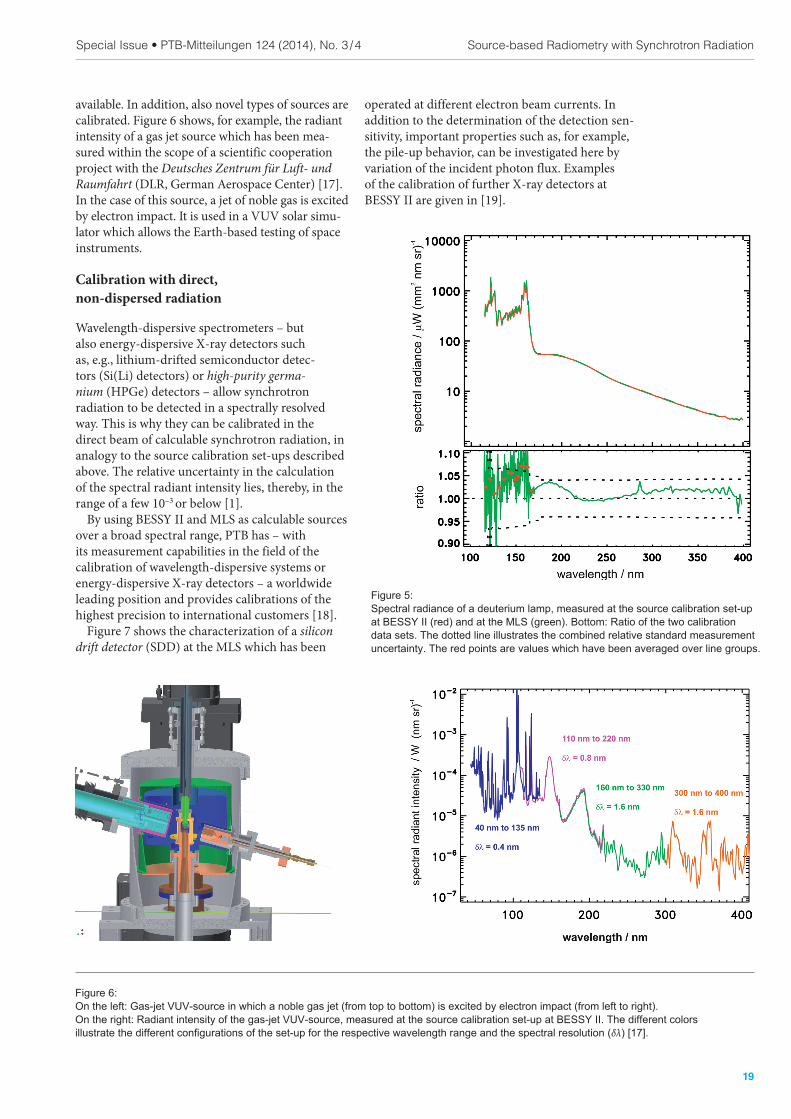
available. In addition, also novel types of sources are calibrated. Figure 6 shows, for example, the radiant intensity of a gas jet source which has been mea-sured within the scope of a scientific cooperation project with the Deutsches Zentrum für Luft- und Raumfahrt (DLR, German Aerospace Center) [17]. In the case of this source, a jet of noble gas is excited by electron impact. It is used in a VUV solar simu-lator which allows the Earth-based testing of space instruments.
Calibration with direct,
non-dispersed radiation
Wavelength-dispersive spectrometers – but also energy-dispersive X-ray detectors such as, e.g., lithium-drifted semiconductor detec-tors (Si(Li) detectors) or high-purity germa-nium (HPGe) detectors – allow synchrotron radiation to be detected in a spectrally resolved way. This is why they can be calibrated in the direct beam of calculable synchrotron radiation, in analogy to the source calibration set-ups described above. The relative uncertainty in the calculation of the spectral radiant intensity lies, thereby, in the range of a few 10–3 or below [1].
By using BESSY II and MLS as calculable sources over a broad spectral range, PTB has – with its measurement capabilities in the field of the calibration of wavelength-dispersive systems or energy-dispersive X-ray detectors – a worldwide leading position and provides calibrations of the highest precision to international customers [18].
Figure 7 shows the characterization of a silicon drift detector (SDD) at the MLS which has been
Figure 6:
On the left: Gas-jet VUV-source in which a noble gas jet (from top to bottom) is excited by electron impact (from left to right). On the right: Radiant intensity of the gas-jet VUV-source, measured at the source calibration set-up at BESSY II. The different colors illustrate the different conigurations of the set-up for the respective wavelength range and the spectral resolution (δλ) [17].
Figure 5: Spectral radiance of a deuterium lamp, measured at the source calibration set-up at BESSY II (red) and at the MLS (green). Bottom: Ratio of the two calibration data sets. The dotted line illustrates the combined relative standard measurement uncertainty. The red points are values which have been averaged over line groups.

20
Special Issue • PTB-Mitteilungen 124 (2014), No. 3 / 4Metrology with Synchrotron Radiation
In the spectral range of higher photon energies, measurements can, in addition, be performed at the wavelength shifter (WLS) of the BAMline B5 [5, 20] which is used jointly with the Bundesanstalt für Materialforschung und -prüfung (BAM, Federal Institute for Materials Research and Testing). Here, the spectrum is clearly harder and one obtains correspondingly higher count rates at high photon energy. The energy-dispersive detectors calibrated in this way are used, for example, in the reference-free X-ray fluorescence analysis [21].
Due to the commissioning of a large vacuum tank, also large spectrographs can be characterized directly at the MLS with calculable synchrotron radiation. This is, for example, done within the scope of cooperation projects for space missions (as described in [16]). As described above, flexi-bility in the selection of the electron energy is very important for the suppression or estimation of the influence of higher diffraction orders. In addition, the great dynamics in the variation of the radiant intensity allows the linearity of the detection systems to be investigated. Spectrographs for solar missions often measure emission lines of highly charged ions which have very different intensities. The intensity behavior, in turn, allows conclusions on solar-physical properties to be drawn. The SPICE spectrograph of the Solar Orbiter Mission will be calibrated in this way with the direct, cal-culable radiation of the MLS [22 ].
Figure 7: Characterization of a silicon drift detector at the MLS: The dotted line shows the calculated, incident photon lux of the primary source MLS, the colored curves show the spectra measured at different incident photon rates which can be varied by means of the stored electron current as indicated within the igure. All spectra have been scaled relating to the electron current of 1μA. The light-blue curve and the red curve have been measured with a modiied adjustment of the detector electronics (130 kcps) which has been optimized for high count rates. Saturation and pile-up effects are visible by the relative signal decrease at high photon rates at lower photon energies and the relative signal increase at low photon rates at higher photon energies, respectively.
References
[1] R. Klein, R. hornagel, G. Ulm: in this publication
on p. 7
[2] R. hornagel, R. Klein, G. Ulm: Metrologia 38,
385 (2001)
[3] R. Klein et al.: Phys. Rev. ST Accel.
Beams 11, 110701 (2008)
[4] J. Schwinger: Phys. Rev. 75, 1912 (1949)
[5] M. Richter, G. Ulm: in this publication on p. 3
[6] R. hornagel, R. Klein, S. Kroth, W. Paustian,
M. Richter: Metrologia 51, 528 (2014)
[7] R. hornagel, R. Fliegauf, R. Klein, S. Kroth,
W. Paustian, M. Richter: Rev. Sci. Instr. 86,
013106 (2015)
[8] M. Richter, J. Hollandt, U. Kroth, W. Paustian,
H. Rabus, R. hornagel, G. Ulm: Nucl. Instr. and
Meth. 467–468, 605 (2001)
[9] M. Richter, J. Hollandt, U. Kroth, W. Paustian,
H. Rabus, R. hornagel, G. Ulm:
Metrologia 40, 107 (2003)
[10] U. Arp et al.: Metrologia 48, 261 (2011)
[11] K. Danzmann, M. Günther, J. Fischer, M. Kock,
M. Kühne: Appl. Opt. 27, 4947 (1988)
[12] J. Hollandt, M. C. E. Huber, M. Kühne:
Metrologia 30, 381 (1993)
[13] J. Hollandt, M. Kühne, B. Wende: Appl. Opt. 33,
68 (1994)
[14] M. Richter, A. Gottwald, F. Scholze, R. hornagel,
G. Ulm: Advances in Space Research 37,
265 (2006)
[15] M. Richter, A. Gottwald, M. Krumrey, W. Paus-
tian, F. Scholze, R. hornagel, G. Ulm: PTB-Mitteilungen 115, 218 (2005)
[16] A. Gottwald, R. Klein, M. Krumrey, P. Müller,
W. Paustian, T. Reichel, F. Scholze, R. hornagel:
in this publication on p. 30
[17] M. Sznajder, T. Renger, A. Witzke, U. Geppert,
R. hornagel: Advances in Space Research 52,
1993 (2013)
[18] M. Krumrey, F. Scholze, G. Ulm:
Proc. SPIE 5501, 277 (2004)
[19] W. Paustian, M. Richter, F. Scholze, R. hornagel,
G. Ulm: PTB-Mitteilungen 115, 181 (2005)
[20] R. Klein, G. Brandt, L. Cibik, M. Gerlach,
M. Krumrey, P. Müller, G. Ulm, M. Scheer:
Nucl. Instr. Meth. A580, 1536 (2007)
[21] M. Müller et al.: in this publication on p. 57
[22] A. Fludra et al.: Proc. SPIE 8862, 88620F (2013)