tfizweb.elte.hu/download/fizikus-msc/anyagfizika/anyagfiz004.pdf · na source-\aa> y s^ 1.27 mev...
TRANSCRIPT
. . ""• * - - .
T . . - ..
.- - ,.
'
-., •7-1. 'Vi t-
• ••
A H». f-
)
.-. . ,\\ .
i'
«. ; - '
f
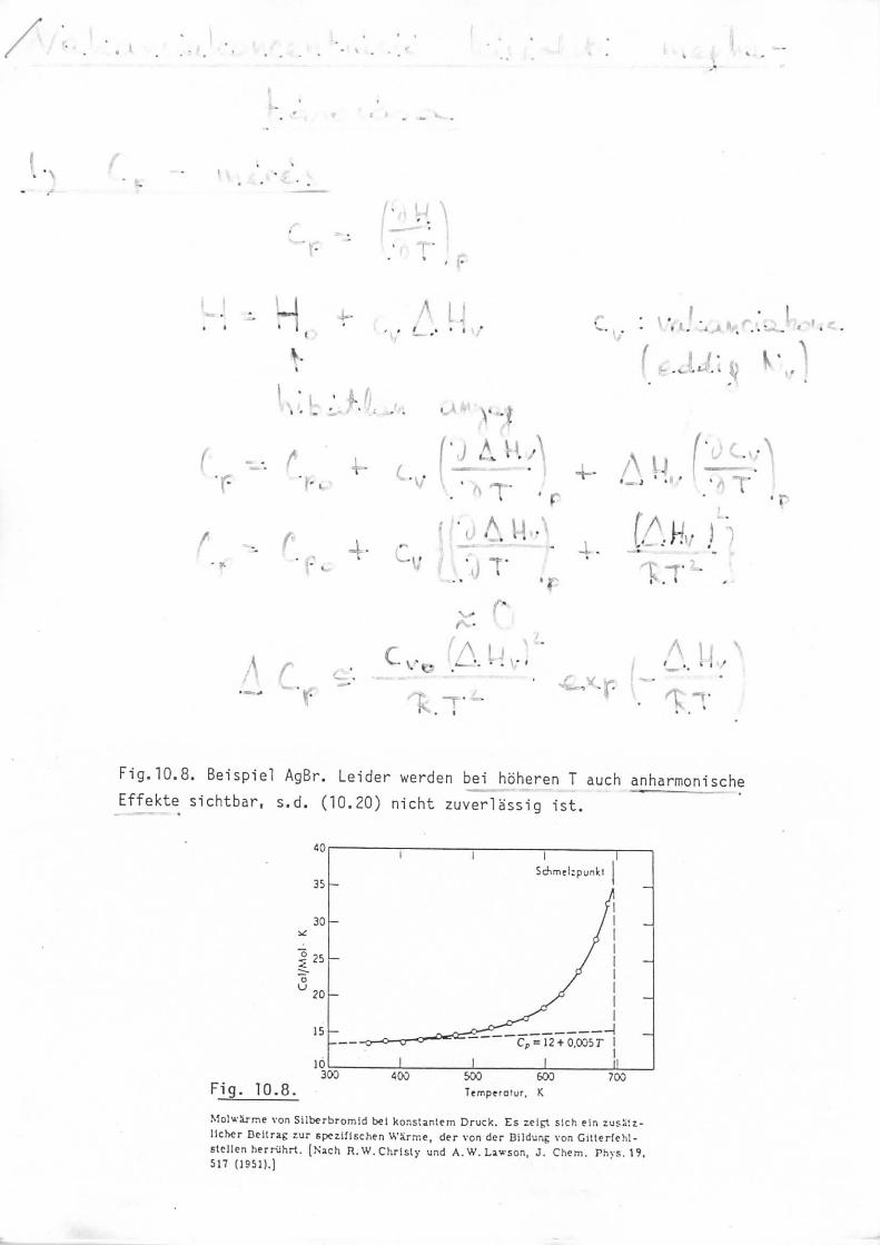
Fig.10.8. Beispiel AgBr. Lender warden bei hoheren T auch anharmom'sche
Effekte slchtbar, s.d. (10.20) nicht zuverlassig 1st.
35
30
20
Fig. 10.8.
15
101300
Cp = 12 +0.035 F '
400 500 600T e m p e r o t u r , K
700
me von Silberbromid bcl k o n s t a n l e m Druck. Es zel£l s ich ein zusSlz-licher Dcllraf: zur eperilischen Wkrme , der von der Bi ldung von G i t l e r f e h l -steJlen herruhrt . [Sach R . W . Chris ty und A. W. Larson, J. Chem. P h y s . 1 9 .517 (1951).]

.
*-*Ts'*
•»*w*ir•r I
<0 It- 0)QJ -r-O. C/JE t/>0) :ia
—
••'
V
" *-..
-
•*sai » i
^ **J
\
\ N t. "i
c t. - LJ :
0)1•r-Ll.
QJ ra-c cO U
-C QJ
QJQD
Oo
QJCn +J
•r- W
Ll- I-cu
-^ QJO ,—13 i—<o a>
Q.Q) Q.
-C OQJ Q
I- 21
to UJV)
•I- 1-C QJ
-Q -oQJ01 t_I- O
LU XIfO
cn (^
ci ^QJ
01 j_ t.'»- 3 «3U_ 4-> JD
pump
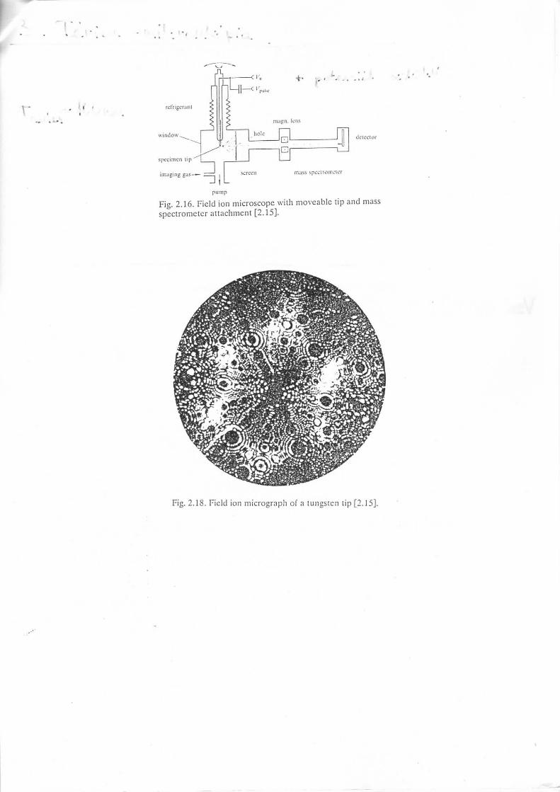
Fig. 2.16. Field ion microscope with moveablc tip and massspectrometer attachment [2.15].
Fig. 2.18. Field ion micrograph of a tungsten tip [2.15].
0;oft
FTV)-l
o-
» i0 f>0 S"
p>-5
ij
CX^
i
•• •
V
,
"O
II
H-N0
fvj
O
r?
H
if
0
8
.
l«i -
OI I
rnIInr>
I!
nro
I)
NaSource
-\AA> y s^1.27 MeV
Scintillator
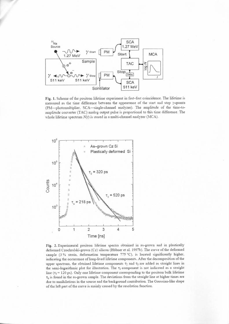
Fig. 1. Scheme of the positron lifetime experiment in fast-fast coincidence. The lifetime ismeasured as the time difference between the appearance of the start and stop "/-quanta(PM—photomultiplier, SCA—single-channel analyzer). The amplitude of the time-to-amplitude converter (TAC) analog output pulse is proportional to this time difference. The\vhole lifetime spectrum N(t) is stored in a multi-channel analyzer (MCA).
10eF
10-
cn
I 10*oO
1QJ r
As-grown CzSi
Plastically deformed Si
0 1 2 3 4 5
Time [ns|
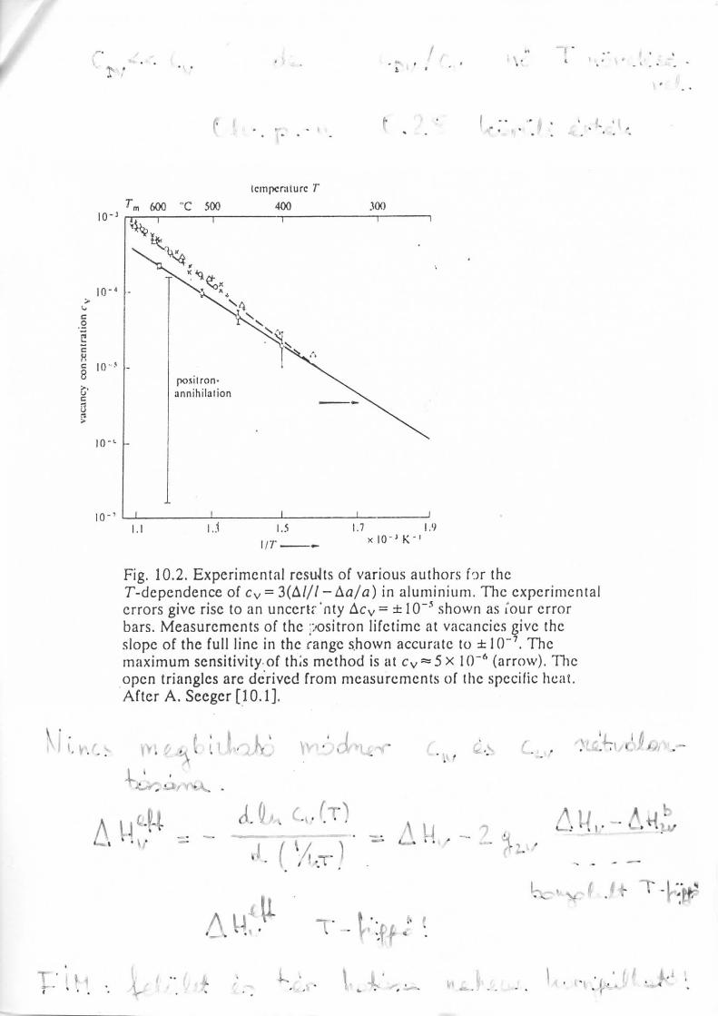
Fig. 2. Experimental positron lifetime spectra obtained in as-grown and in plasticallydeformed Czochralski-grown (Cz) silicon (Htibner et al. 1997b). The curve of the deformedsample (3 % strain, deformation temperature 775 °C). is located significantly higher,indicating the occurrence of long-lived lifetime components. After the decomposition of theupper spectrum, the obtained lifetime components T^ and 13 are added as straight lines inthe semi-logarithmic plot for illustration. The TI component is not indicated as a straightline {TI = 120 ps). Only one lifetime component corresponding to the positron bulk lifetimeTb is found in the as-grown sample. The deviations from the straight line at higher times aredue to annihilations in the source and the background contribution. The Gaussian-like shapeof the left part of the curve is mainly caused by the resolution function.

* .
I; ,4 i ' - I •» ; * ' • * . . . » • • ..
• r
A
u
•
.'
! - ' . \' V ':S .
..4! .V l.i- U
,1 ,
•4,
u.

'
V
V *- ~M?
«lf»•3*
-w "5"^V
-^<=s
ii
-"'''W**^.
<;*"*. *1 i
,
-
w
<^
•*s-'
-
4'™ *•*i.4
^;
O
,v/.
-.
o
.-*V^
. « •
r
• :V
10-Tm 600 "C 500
(crnpcrnturc
400 300
[0
CH8 I0
'
i nI.I 1..1 1.5 1.7 1.9
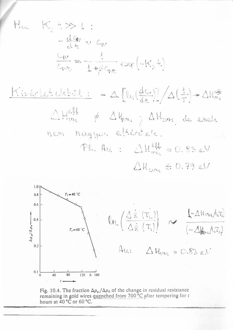
Fig. 10.2. Experimental results of various authors fo r theT-dependence of cv = 3(A///~Aa/a) in a luminium. The experimentalerrors give rise to an unccr t r 'n ty Acv = ± lO""* shown as Tour errorbars. Measurements of the positron l i f e t ime at vacancies give theslope of the f u l l line in the range shown accurate to ±10"7. Themaximum sensitivity of this method is at Cy^S x IO"6 (arrow). Theopen triangles are derived from measurements of the specific heat.After A. Seeger [10.1].
.'•' ^ r ' " ' — ' » ' ' - ' , .- ' _ , . , • . . . • - < •
: .

'V
•' •;
,<•"• L ' - i / \
•^ \
* ••^y-*~* » - -n-i* o^*«&• • » •* * > v *»^
*
7 J
•-,
/
•-> ,*> -://; i/ 'y/ •. * / - . <'
V* Y3
•. A
O
.., o-e TiJL.
"*'*
Vv
V ,.;-*" -,-
J.
*4- ."
-V ,| , *j"

,,
' - ' ' I '
a - • i\s• t •
•
JUr
. - C;,? *•• v/Ja'J
K /V
-^A -t
A \
•
• • - *•• / > . , . « . - v -
•<
. .!^* f l
.«
2a V«
. '. ' ' .
! aU i v /

')
6' AC j\V \7
\
*
i u '
-
•
'
-'
• ~*
T
•
A - 1
^L'v?^T^* 'V,'i;iQ*• . », - . -
* ' * * I r
- ! . *
, '•
• . - • • - . . ,• MI
/,----' °n
1v * ». • ••
' '.* '
-. & •*:
. ". \-
(* -
A • ; • A U-
f .
\* , - V,
120 h 160
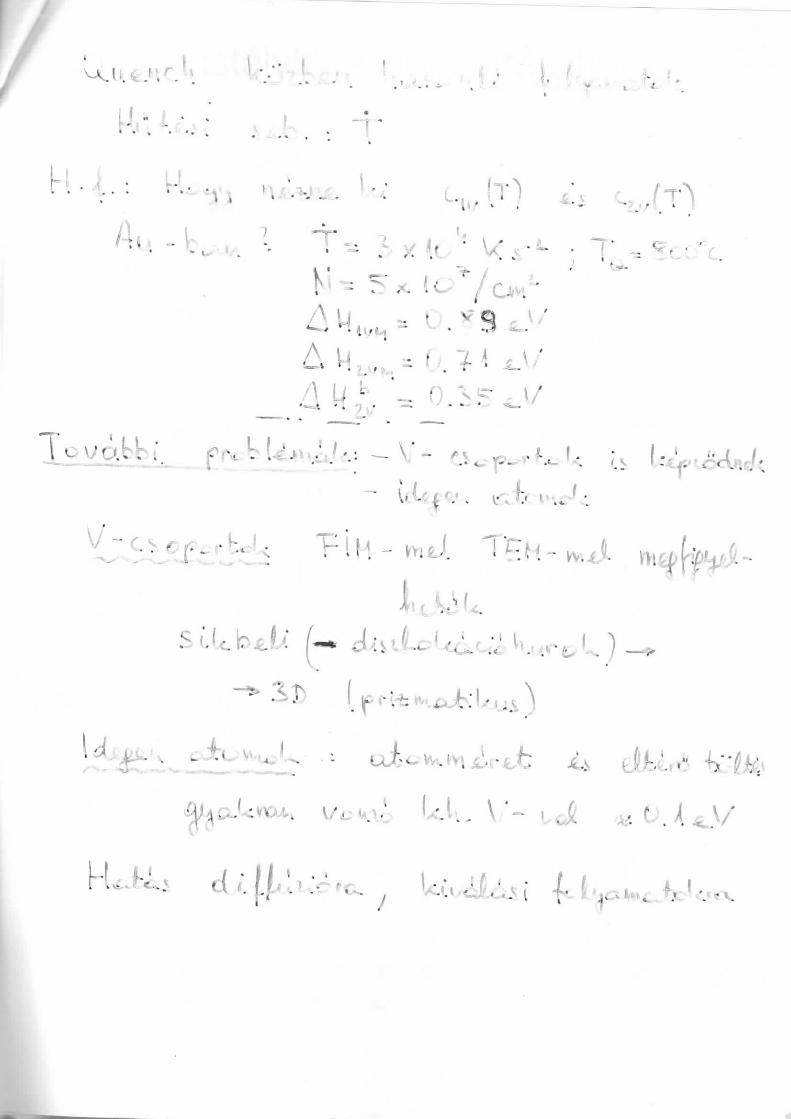
Fig. 10.4. The frac t ion Apc;/Ap0 of the change in res idua l resis tanceremaining in gold wires quenched from 700 °C a f t e r t emper ing for /hours at 40 °C or 60 °C.'
" • *: «. - 1 ' ;- •••'
'
'
•M =F( 0
1 y^-f
• i;
">* wvi "'"ril 'I \
^-- • -• -
13*
- •
•w -»;\ :V^*K^JC^ i
-
-•'• '*
-•
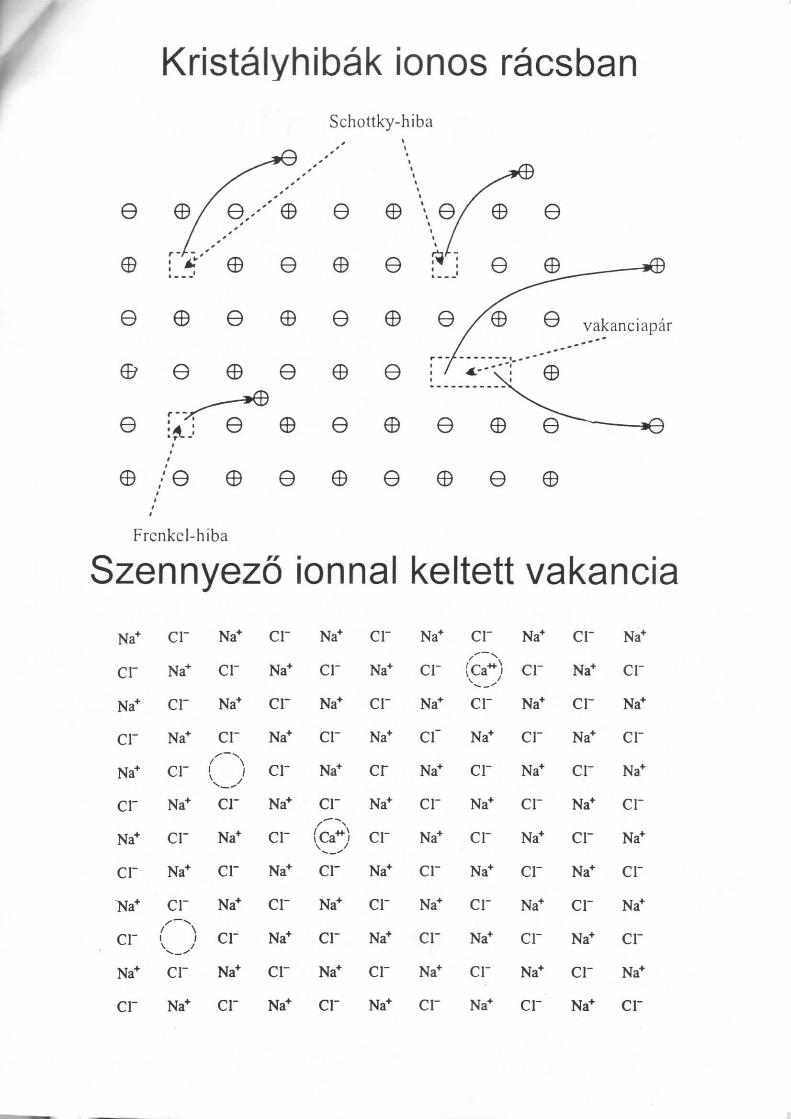
Kristalyhibak ionos racsbanSchottky-hiba
e e
e e
e © e © e
e © ©
e ©
e © e
Frcnkcl-hiba
e © e
Szennyezo ionnal keltett vakancia
Na+
cr
Na+
cr
Na+
cr
Na+
cr
~Na+
cr
Na+
cr
cr
Na+
cr
Na+
cr
Na+
cr
Na*
cr
( ")
cr
Na+
Na*
cr
Na+
crX""Nocr
Na+
cr
Na*
cr
Na*
cr
cr
Na*
cr
Na*
cr
Na*
cr
Na+
crNa+
cr
Na+
Na+
cr
Na+
crNa+
cr
©cr
Na+
cr
Na*
cr
cr
Na*
cr
Na+
crNa*
cr
Na*
cr
Na*
cr
Na+
Na+
crNa*
crNa^
crNa+
cr
Na+
cr
Na+
cr
cr
©cr
Na+
cr
Na+
cr
Na+
crNa+
crNa+
Na+
cr
Na+
cr
Na+
cr
Na+
cr
Na+
cr
Na+
cr
cr
Na+
cr
Na*
cr
Na+
cr
Na+
cr
Na+
cr
Na*
Na*
cr
Na*
cr
Na*
cr
Na*
cr
Na*
cr
Na+
cr
Nem fuggetlen ponthibak
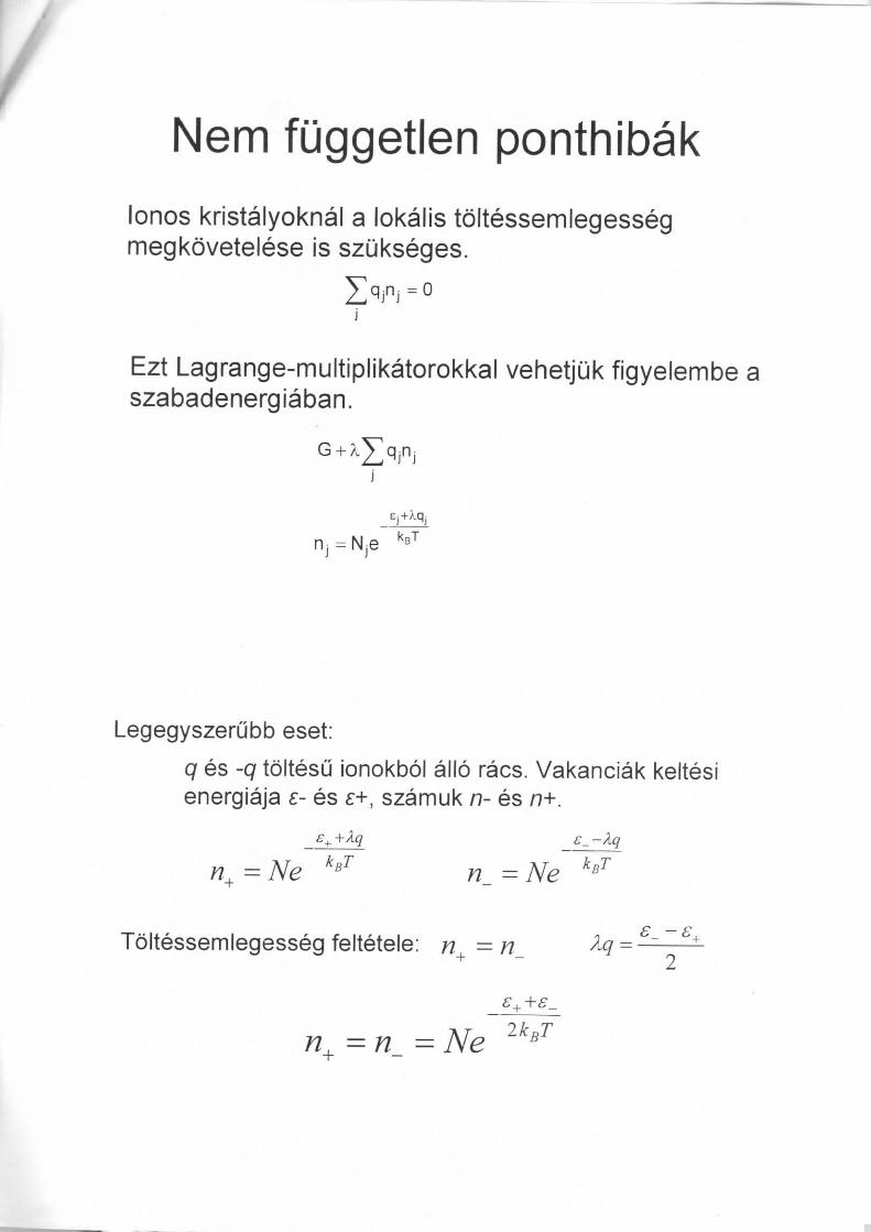
lonos kristalyoknal a lokalis tdltessemlegessegmegkdvetelese is szukseges.
Ezt Lagrange-multiplikatorokkal vehetjuk figyelembe aszabadenergiaban.
Legegyszerubb eset:
q es -q toltesu ionokbol allo racs. Vakanciak keltesienergiaja e- es £+, szamuk n- es n+.
s_ —
n+=Ne
Toltessemlegesseg feltetele: n = n
A Tn - Ne
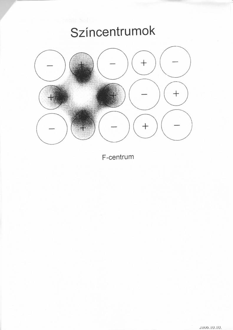
Szincentrumok
F-centrum
/UUD.IU.iU.
Bonding in Materials
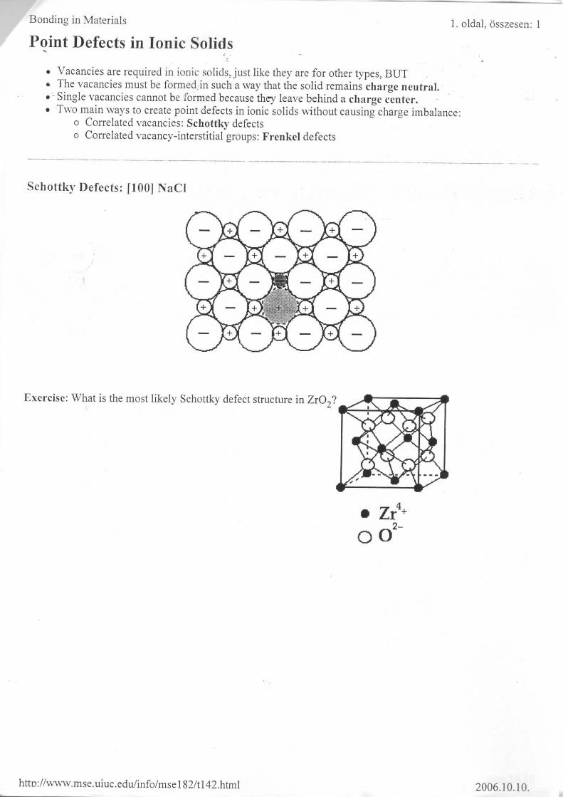
Point Defects in Ionic Solids
1. oldal, osszesen: 1
Vacancies are required in ionic solids, just like they are for other types, BUTThe vacancies must be formed:in such a way that the solid remains charge neutral.Single vacancies cannot be formed because they leave behind a charge center.Two main ways to create point defects in ionic solids without causing charge imbalance:
o Correlated vacancies: Schottky defectso Correlated vacancy-interstitial groups: Frenkel defects
Schottky Defects: [100) NaCI
Exercise: What is the most likely Schottky defect structure in Zr02?
00
httD://www.mse.uiuc.edu/info/msel82/tl42.html 2006.10.10.

Bonding in Materials
Point Defects in Ionic Solids
Frenkel Defects: [100] MgO
1. oldal, osszesen: 1
Exercise: What is the most likely Frenkel defect in ZrO2?
http://w\v\v.mse.uiuc.edu/info/msel82/tl43.html 2006.10.10.