soundersuite - usb software user manual · users. it uses dde data transfer protocol to interface...
TRANSCRIPT

SounderSuite - USB
Software User Manual
Complete Reference
D101-04969Revision 2.0
December 22, 2010
Knudsen Engineering Limited10 Industrial Road
Perth, Ontario, Canada

SOFTWARE INSTALLATION ANDFIRMWARE UPGRADE
D101-04383-Rev2.2
ECHOCONTROL SERVER
D101-04381-Rev2.1
ECHOCONTROL CLIENT
D101-04380-Rev2.01
POSTSURVEY
D101-03175-Rev4.0
FIRMWARE LOADER
D101-04382-Rev2.0
CONVERSION UTILITY
D101-04968-Rev1.1
FILE SPECIFICATION: KEL D3 KEB
D101-04842-Rev1.2
FILE SPECIFICATION: SEG-Y
D101-03021-Rev2.2
FILE SPECIFICATION: XTF
D101-03322-Rev2.2
ECHOSOUNDER CONCEPTS
D101-02251-Rev4.1
Formatted for AVERY Ready Index Tbl. Cont. 12 tab

SounderSuite - USB
Windows Installation and Firmware Upgrades
Supports Software Installer Package #: D429-04216
D101-04383Revision 2.2
December 22, 2010
Knudsen Engineering Limited10 Industrial Road
Perth, Ontario, Canada

CONTENTS
1 INTRODUCTION. . . . . . . . . . . . . . . . . . . . . . . . . . . . . . . . . . . . . . . . . . . . . . . . . . . . . . . . . . . . . . . . . . . . . . . . . 1-11.1 About this manual. . . . . . . . . . . . . . . . . . . . . . . . . . . . . . . . . . . . . . . . . . . . . . . . . . . . . . . . . . . . . . . . . . . 1-11.2 Technical Support. . . . . . . . . . . . . . . . . . . . . . . . . . . . . . . . . . . . . . . . . . . . . . . . . . . . . . . . . . . . . . . . . . . 1-1
2 SOFTWARE DEFINITIONS. . . . . . . . . . . . . . . . . . . . . . . . . . . . . . . . . . . . . . . . . . . . . . . . . . . . . . . . . . . . . . . . . 2-12.1 Overview. . . . . . . . . . . . . . . . . . . . . . . . . . . . . . . . . . . . . . . . . . . . . . . . . . . . . . . . . . . . . . . . . . . . . . . . . . 2-1
2.1.1 Firmware. . . . . . . . . . . . . . . . . . . . . . . . . . . . . . . . . . . . . . . . . . . . . . . . . . . . . . . . . . . . . . . . . . . . 2-12.1.2 Windows Support Applications. . . . . . . . . . . . . . . . . . . . . . . . . . . . . . . . . . . . . . . . . . . . . . . . . . 2-1
2.1.2.1 EchoControl Server (EchoControlServer.exe). . . . . . . . . . . . . . . . . . . . . . . . . . . . . . . . 2-12.1.2.2 EchoControl Client (EchoControlClient.exe). . . . . . . . . . . . . . . . . . . . . . . . . . . . . . . . . 2-12.1.2.3 PostSurvey (PostSurvey.exe).. . . . . . . . . . . . . . . . . . . . . . . . . . . . . . . . . . . . . . . . . . . . . 2-12.1.2.4 Hypack Device Driver (EchoHypackDLL.dll). . . . . . . . . . . . . . . . . . . . . . . . . . . . . . . . 2-12.1.2.5 Firmware Loader (FirmwareLoader.exe). . . . . . . . . . . . . . . . . . . . . . . . . . . . . . . . . . . . 2-1
3 INSTALLATION / UPGRADE GUIDELINES. . . . . . . . . . . . . . . . . . . . . . . . . . . . . . . . . . . . . . . . . . . . . . . . . . . 3-13.1 Initial Installation.. . . . . . . . . . . . . . . . . . . . . . . . . . . . . . . . . . . . . . . . . . . . . . . . . . . . . . . . . . . . . . . . . . . 3-13.2 System Upgrades. . . . . . . . . . . . . . . . . . . . . . . . . . . . . . . . . . . . . . . . . . . . . . . . . . . . . . . . . . . . . . . . . . . . 3-1
4 PC SOFTWARE INSTALLATION. . . . . . . . . . . . . . . . . . . . . . . . . . . . . . . . . . . . . . . . . . . . . . . . . . . . . . . . . . . . 4-14.1 Setup Procedure. . . . . . . . . . . . . . . . . . . . . . . . . . . . . . . . . . . . . . . . . . . . . . . . . . . . . . . . . . . . . . . . . . . . . 4-1
4.1.1 Special Notes regarding Windows 2000/XP/Vista/7. . . . . . . . . . . . . . . . . . . . . . . . . . . . . . . . . . 4-54.2 Driver Installation for Single-Channel Modules. . . . . . . . . . . . . . . . . . . . . . . . . . . . . . . . . . . . . . . . . . . . 4-5
4.2.1 Recommended Installation. . . . . . . . . . . . . . . . . . . . . . . . . . . . . . . . . . . . . . . . . . . . . . . . . . . . . . 4-54.2.2 Advanced Installation. . . . . . . . . . . . . . . . . . . . . . . . . . . . . . . . . . . . . . . . . . . . . . . . . . . . . . . . . . 4-8
5 FIRMWARE INSTALLATION. . . . . . . . . . . . . . . . . . . . . . . . . . . . . . . . . . . . . . . . . . . . . . . . . . . . . . . . . . . . . . . 5-15.1 Upgrading the Firmware. . . . . . . . . . . . . . . . . . . . . . . . . . . . . . . . . . . . . . . . . . . . . . . . . . . . . . . . . . . . . . 5-1
The information contained in this document is proprietary data of Knudsen Engineering Limited. Any disclosure, use or reproduction of this information for other than thespecific purpose intended is expressly prohibited unless agreed to in writing by Knudsen Engineering Limited.
D101-04383-Rev2.2 December 22, 2010 Page 2 of 16

SounderSuite-USB: Windows Installation / Firmware Upgrades 1-1
1 INTRODUCTION
1.1 About this manual
This manual provides installation and upgrade details for the software package provided with a 1600 or 3200 SeriesEchosounder. It provides brief descriptions of the Windows software applications and the embedded firmware. It explainswhat needs to be installed for a newly delivered system and what needs to be done to upgrade an existing system.
1.2 Technical Support
For technical support or to report problems please contact your local representative or:
Technical SupportKnudsen Engineering Limited 10 Industrial RoadPerth, OntarioK7H 3P2
Voice: (613) 267-1165 8:30 am to 5:00 pm E.S.T. Core HoursFax: (613) 267-7085E-Mail: [email protected]: http://knudsenengineering.com/
The information contained in this document is proprietary data of Knudsen Engineering Limited. Any disclosure, use or reproduction of this information for other than thespecific purpose intended is expressly prohibited unless agreed to in writing by Knudsen Engineering Limited.
D101-04383-Rev2.2 December 22, 2010 Page 3 of 16

2-1 SounderSuite-USB: Windows Installation / Firmware Upgrades
2 SOFTWARE DEFINITIONS
2.1 Overview
Virtually every aspect of the USB Echosounder's functionality is defined and controlled by software. This software includesthe "firmware" which resides in non-volatile memories within the echosounder itself, and various Windows-compatiblesupport applications which run on the host PC.
2.1.1 Firmware
The term firmware refers to the software which resides in nonvolatile memory within the Echosounder modules. Upgradesand revisions are distributed periodically as “.bin" files which can be re-programmed into the echosounder module in the fieldby the user. 2.1.2 Windows Support Applications
There are various Windows applications provided with the USB Echosounders for different support purposes. All theprograms are Windows compatible, and are installed with a standard Setup.exe process.
2.1.2.1 EchoControl Server (EchoControlServer.exe)
This program is an independent Windows application that interfaces to the Echosounder via a USB interface. The USBinterface must be connected and functioning for this application to be usable. It provides the interconnection between theechosounder hardware on the host PC to the client application on the same PC or another one on the same network. It alsoprovides the interfaces for the peripheral device inputs. This application must be active on the host PC for the clientapplication to communicate properly with the echosounder hardware.
2.1.2.2 EchoControl Client (EchoControlClient.exe)
This program is an independent Windows application that interfaces to the server application via TCP/IP networkcommunications. The server application must be running and successfully connected to the sounder for this application tobe usable. It provides scrolling echogram image displays with echosounder operating controls, and controls for data loggingand recording functions.
2.1.2.3 PostSurvey (PostSurvey.exe)
This program is an independent Windows application that provides the user playback and printing capabilities for theechogram data recorded by the EchoControlClient application.
2.1.2.4 Hypack Device Driver (EchoHypackDLL.dll)
This program is provided as a device driver to Coastal Oceanographics HYPACK for Windows hydrographic survey software,in the DLL (Dynamic Link Library) format required by HYPACK. This program is only useful to HYPACK for Windowsusers. It uses DDE data transfer protocol to interface with the EchoControlClient application.
2.1.2.5 Firmware Loader (FirmwareLoader.exe)
This program is a very simple Windows interface program. It communicates with the echosounder through the USB port onthe server host PC. It provides simple firmware upgrade capabilities.
The information contained in this document is proprietary data of Knudsen Engineering Limited. Any disclosure, use or reproduction of this information for other than thespecific purpose intended is expressly prohibited unless agreed to in writing by Knudsen Engineering Limited.
D101-04383-Rev2.2 December 22, 2010 Page 4 of 16

SounderSuite-USB: Windows Installation / Firmware Upgrades 3-1
3 INSTALLATION / UPGRADE GUIDELINES
3.1 Initial Installation
A newly delivered echosounder has the necessary firmware already programmed into it. The user only needs to load theWindows support applications supplied on the CD-ROM. The CD-ROM contains a Setup.exe Windows installation programthat creates the directory and copies all the files onto the user’s hard disk. See Chapter 4 for a complete description of theinstallation process.
3.2 System Upgrades
Occasionally, a system that has already been operating out in the field will be provided an upgrade software package toprovide additional operating features not available with the original software. If the Echosounder’s firmware is not at theproper revision, it will need to be upgraded. See Chapters 4 and 5 for detailed descriptions of the installation processes.
NOTE: When performing the upgrade, always perform the Windows upgrade first, as this will extract the necessary “.bin”file onto the hard disk required to proceed with the firmware upgrade.
The information contained in this document is proprietary data of Knudsen Engineering Limited. Any disclosure, use or reproduction of this information for other than thespecific purpose intended is expressly prohibited unless agreed to in writing by Knudsen Engineering Limited.
D101-04383-Rev2.2 December 22, 2010 Page 5 of 16

4-1 SounderSuite-USB: Windows Installation / Firmware Upgrades
4 PC SOFTWARE INSTALLATION
4.1 Setup Procedure
The CD-ROM provided either with a new system or in an upgrade package contains a typical Windows Setup(SounderSetup.exe) installation program. For most Windows systems, this Setup executable will automatically run (autorun)when the CD-ROM is loaded in the drive. If it does not start automatically, simply run the file SounderSetup.exe.
Sometimes the upgrade package is provided by an e-mail or weblink download. In that case, the installer package filenamewill incorporate the release serial number: ie K206-0110-USB.exe. This is still a standard Windows executable and can berun the same as a Setup.exe file.
When the installer program is run, it displays a number of information and configuration prompts to allow the user tocustomize the installation process if desired. Customization of the installation should be undertaken by advanced users only.The normal installation process proceeds as follows:
Welcome to the SounderSuite-USB Setup Wizard: Simply click Next to continue.
The information contained in this document is proprietary data of Knudsen Engineering Limited. Any disclosure, use or reproduction of this information for other than thespecific purpose intended is expressly prohibited unless agreed to in writing by Knudsen Engineering Limited.
D101-04383-Rev2.2 December 22, 2010 Page 6 of 16

SounderSuite-USB: Windows Installation / Firmware Upgrades 4-2
Select Destination Location: Default: C:\Program Files\SounderSuite-USBIf there are any batch files for managing multiple configurations, they will be hardcoded to this folder for now. It isrecommended that only advanced users modify this option.
Setup Components: Default: Stand-aloneThere are three options available for this item. The required installation depends on the usage of the sounder. The simplestis to load the recommend default Stand-alone and run the sounder from the same PC it is connected to (host PC). It is
The information contained in this document is proprietary data of Knudsen Engineering Limited. Any disclosure, use or reproduction of this information for other than thespecific purpose intended is expressly prohibited unless agreed to in writing by Knudsen Engineering Limited.
D101-04383-Rev2.2 December 22, 2010 Page 7 of 16

4-3 SounderSuite-USB: Windows Installation / Firmware Upgrades
possible to connect the sounder to one PC and control it from another. That’s where the Server-side (PC connected to thesounder) and Client-side (another computer on the network) can be used. They only load the application components requiredfor each side of the operations.
For now, this document assumes that the echosounder is controlled from the same PC to which it is connect (Stand-alone).
Select Start Menu Folder: Default: SounderSuite-USBThis can be modified to any preferred value. Please note that all the following documentation assumes that the defaults havebeen used.
The information contained in this document is proprietary data of Knudsen Engineering Limited. Any disclosure, use or reproduction of this information for other than thespecific purpose intended is expressly prohibited unless agreed to in writing by Knudsen Engineering Limited.
D101-04383-Rev2.2 December 22, 2010 Page 8 of 16

SounderSuite-USB: Windows Installation / Firmware Upgrades 4-4
Select Additional Tasks: Default: Desktop IconsThis can be modified to any preferred value. Please note that all the following documentation assumes that the defaults havebeen used.
Ready to Install: Last chance to cancel before actual installation is performed. Click Next to proceed with the installation.The installer will proceed to copy the application executables, driver setups, firmware files, and support documentation inPDF format. After completing these tasks, a final screen will appear indicating if the setup completed successfully.
The information contained in this document is proprietary data of Knudsen Engineering Limited. Any disclosure, use or reproduction of this information for other than thespecific purpose intended is expressly prohibited unless agreed to in writing by Knudsen Engineering Limited.
D101-04383-Rev2.2 December 22, 2010 Page 9 of 16

4-5 SounderSuite-USB: Windows Installation / Firmware Upgrades
If the installation process is being performed for a new unit, the process is now complete. The sounder will have been shippedwith the appropriate firmware revisions. If this is an upgrade package, the firmware in the sounder will probably need to beupgraded as well. Please see Chapter 5 for detailed information regarding the firmware upgrade.
Once the installer has completed and restarted, you should see a series of new icons on the desktop. These icons arealso available in the Program Group accessible from the Start button.
4.1.1 Special Notes regarding Windows 2000/XP/Vista/7
Because the installer package needs to install driver services and class components, the installation must be done using anadministrative account.
4.2 Driver Installation for Single-Channel Modules
When the Windows software installer was run, it installed all the necessary driver files to support the sounder. In the idealsituation, Windows will automatically recognize the new driver and load the driver by itself when it detects the sounder’sinternal modules. This is not always the case, though, and the user may need to provide additional direction for Windows tosuccessfully complete the loading of the hardware driver.
4.2.1 Recommended Installation
The first time the sounder is connected and powered on, Windows should indicate that it sees new hardware called a Single-Channel Module and should activate the New Hardware Wizard.
Welcome to the Found New Hardware Wizard: The wizard will ask if it should access the internet to search for the driverfor the module. The driver has been loaded on the hard drive so the user should select “No, not this time” and click Next.
The information contained in this document is proprietary data of Knudsen Engineering Limited. Any disclosure, use or reproduction of this information for other than thespecific purpose intended is expressly prohibited unless agreed to in writing by Knudsen Engineering Limited.
D101-04383-Rev2.2 December 22, 2010 Page 10 of 16

SounderSuite-USB: Windows Installation / Firmware Upgrades 4-6
The next dialog asks if the software should be installed automatically (Recommended) or from a list or specific location(Advanced). Normally, the user should be able to select the automatic (Recommended) option, given that the installerapplication will have already loaded all the necessary files. If it was successful in doing so, the wizard should find the driverfiles and loaded them without any user assistance.
Once it has completed, it will indicate whether or not it was successful in installing the software for the module. If it was theuser can simply click on Finish to continue. If the sounder has more than one channel, this step needs to be repeated for each
The information contained in this document is proprietary data of Knudsen Engineering Limited. Any disclosure, use or reproduction of this information for other than thespecific purpose intended is expressly prohibited unless agreed to in writing by Knudsen Engineering Limited.
D101-04383-Rev2.2 December 22, 2010 Page 11 of 16

4-7 SounderSuite-USB: Windows Installation / Firmware Upgrades
channel module detected in the sounder.
The information contained in this document is proprietary data of Knudsen Engineering Limited. Any disclosure, use or reproduction of this information for other than thespecific purpose intended is expressly prohibited unless agreed to in writing by Knudsen Engineering Limited.
D101-04383-Rev2.2 December 22, 2010 Page 12 of 16
SounderSuite-USB: Windows Installation / Firmware Upgrades 4-8
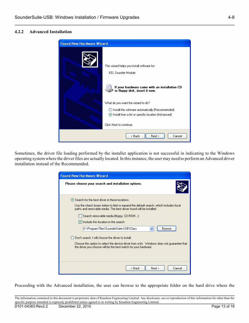
4.2.2 Advanced Installation
Sometimes, the driver file loading performed by the installer application is not successful in indicating to the Windowsoperating system where the driver files are actually located. In this instance, the user may need to perform an Advanced driverinstallation instead of the Recommended.
Proceeding with the Advanced installation, the user can browse to the appropriate folder on the hard drive where the
The information contained in this document is proprietary data of Knudsen Engineering Limited. Any disclosure, use or reproduction of this information for other than thespecific purpose intended is expressly prohibited unless agreed to in writing by Knudsen Engineering Limited.
D101-04383-Rev2.2 December 22, 2010 Page 13 of 16

4-9 SounderSuite-USB: Windows Installation / Firmware Upgrades
necessary files are stored. In a default installation, this would be the folder C:\Program Files\SounderSuite-USB\Class. Asfor the Recommended installation, the operating system will load the driver files located in the indicated folder for themodule.
Once it has completed, it will indicate whether or not it was successful in installing the software for the module. If it was,the user can simply click on Finish to continue. If the sounder has more than one channel, this step needs to be repeated foreach channel module detected in the sounder.
The information contained in this document is proprietary data of Knudsen Engineering Limited. Any disclosure, use or reproduction of this information for other than thespecific purpose intended is expressly prohibited unless agreed to in writing by Knudsen Engineering Limited.
D101-04383-Rev2.2 December 22, 2010 Page 14 of 16

SounderSuite-USB: Windows Installation / Firmware Upgrades 5-1
5 FIRMWARE INSTALLATION
The firmware installation procedures are only required for system upgrades. Newly delivered systems do not need to haveany firmware loaded. Upgrades are performed when new capabilities are added to the echosounder’s functionality. Sometimes only the Windows support software is enhanced and firmware remains unaffected. Often the Windows programwill indicate if a newer version of firmware needs to be loaded; in other instances, there will be instructions provided withthe installation package indicating if an update is required.
A single echosounder may be comprised of a number of hardware channel modules. Upgrading the echosounder involvesdownloading new firmware into these individual modules. Typically, there will be only one type of module and only one“.bin” file will be required. In those rare cases where there is more than one, a readme file will be included to indicate which.bin is required for which hardware module.
5.1 Upgrading the Firmware
The FirmwareLoader application loaded onto the PC by the installer package provides the interface necessary to upgrade thefirmware in the sounder channel modules. The steps to upgrade the hardware modules are as follows:
Step 1. Exit any open SounderSuite windows applications.
Step 2. Power cycle the sounder. The modules will not be able to initiate the firmware loading operation if they havealready run a ping cycle.
Step 3. Run the Firmware Loader application available under the Start -> All Programs -> SounderSuite-USBprogram folder. It should detect the modules in the sounder. If not, it will indicate the appropriate errorcondition.
Step 4. In Firmware Loader, select Upgrades -> Load DSP Firmware. This should cause the application to displaya dialog box labelled Select Sounder Hardware. The drop down list indicates the modules detected.
Step 5. Select a module to update.
Step 6. The application should now provide a dialog box for opening the firmware file. Ideally, it will already belooking at the appropriate folder; if not, browse to the folder C:\Program Files\SounderSuite-USB\Firmware. Select and open the desired .bin file.
Step 7. The application will start the transfer of the firmware to the module. Once it is complete and has passed avalidity check, a dialog will appear asking for confirmation that you do want to reprogram the firmwarecontents in the module. Click on Yes to proceed.
Step 8. The application will display the programming status as it proceeds and indicate once it is completed if it wassuccessful or not.
WARNING: Do NOT turn off the power to the sounder while the programming step is active or the memory in the modulecould be permanently damaged and require return to the factory for reprogramming.
Step 9. Repeat steps 4-8 for the next module.
The Firmware Loader simply replaces the contents of the on-board boot memory. The new firmware is not actually running
The information contained in this document is proprietary data of Knudsen Engineering Limited. Any disclosure, use or reproduction of this information for other than thespecific purpose intended is expressly prohibited unless agreed to in writing by Knudsen Engineering Limited.
D101-04383-Rev2.2 December 22, 2010 Page 15 of 16

5-2 SounderSuite-USB: Windows Installation / Firmware Upgrades
yet. The sounder will need to be rebooted to run the new firmware.
Step 10. Click Close and exit the Firmware Loader application.
Step 11. Power cycle the sounder.
At this point, technically the process is complete but if you wish to verify that the firmware load was completely successfula simple check is in order.
Step 12. Run the Firmware Loader again.
Step 13 Select the Help menu option Sounder Info. This will bring up a Module Summary dialog that shows onetab for each module detected. Listed on this tab is information identifying the module and the firmwaredetected running in it.
The information contained in this document is proprietary data of Knudsen Engineering Limited. Any disclosure, use or reproduction of this information for other than thespecific purpose intended is expressly prohibited unless agreed to in writing by Knudsen Engineering Limited.
D101-04383-Rev2.2 December 22, 2010 Page 16 of 16

SounderSuite - USB
EchoControlServer
Supports Software: D409-04185
D101-04381Revision 2.1
December 22, 2010
Knudsen Engineering Limited10 Industrial Road
Perth, Ontario, Canada

CONTENTS
1 INTRODUCTION. . . . . . . . . . . . . . . . . . . . . . . . . . . . . . . . . . . . . . . . . . . . . . . . . . . . . . . . . . . . . . . . . . . . . . . . . 1-11.1 About this manual. . . . . . . . . . . . . . . . . . . . . . . . . . . . . . . . . . . . . . . . . . . . . . . . . . . . . . . . . . . . . . . . . . . 1-11.2 Technical Support. . . . . . . . . . . . . . . . . . . . . . . . . . . . . . . . . . . . . . . . . . . . . . . . . . . . . . . . . . . . . . . . . . . 1-1
2 OVERVIEW. . . . . . . . . . . . . . . . . . . . . . . . . . . . . . . . . . . . . . . . . . . . . . . . . . . . . . . . . . . . . . . . . . . . . . . . . . . . . . 2-12.1 USB and Network Usage. . . . . . . . . . . . . . . . . . . . . . . . . . . . . . . . . . . . . . . . . . . . . . . . . . . . . . . . . . . . . . 2-12.2 Description.. . . . . . . . . . . . . . . . . . . . . . . . . . . . . . . . . . . . . . . . . . . . . . . . . . . . . . . . . . . . . . . . . . . . . . . . 2-32.3 Taskbar - Restore. . . . . . . . . . . . . . . . . . . . . . . . . . . . . . . . . . . . . . . . . . . . . . . . . . . . . . . . . . . . . . . . . . . . 2-42.4 Taskbar - About EchoControlServer. . . . . . . . . . . . . . . . . . . . . . . . . . . . . . . . . . . . . . . . . . . . . . . . . . . . . 2-42.5 Taskbar - Close. . . . . . . . . . . . . . . . . . . . . . . . . . . . . . . . . . . . . . . . . . . . . . . . . . . . . . . . . . . . . . . . . . . . . 2-4
3 MAIN MENU- System. . . . . . . . . . . . . . . . . . . . . . . . . . . . . . . . . . . . . . . . . . . . . . . . . . . . . . . . . . . . . . . . . . . . . . 3-13.1 Self-Test.. . . . . . . . . . . . . . . . . . . . . . . . . . . . . . . . . . . . . . . . . . . . . . . . . . . . . . . . . . . . . . . . . . . . . . . . . . 3-13.2 Exit.. . . . . . . . . . . . . . . . . . . . . . . . . . . . . . . . . . . . . . . . . . . . . . . . . . . . . . . . . . . . . . . . . . . . . . . . . . . . . . 3-1
4 MAIN MENU - Hide Window. . . . . . . . . . . . . . . . . . . . . . . . . . . . . . . . . . . . . . . . . . . . . . . . . . . . . . . . . . . . . . . . 4-1
5 MAIN MENU - Clear Log. . . . . . . . . . . . . . . . . . . . . . . . . . . . . . . . . . . . . . . . . . . . . . . . . . . . . . . . . . . . . . . . . . . 5-1
6 MAIN MENU - Help. . . . . . . . . . . . . . . . . . . . . . . . . . . . . . . . . . . . . . . . . . . . . . . . . . . . . . . . . . . . . . . . . . . . . . . 6-16.1 Sounder Info. . . . . . . . . . . . . . . . . . . . . . . . . . . . . . . . . . . . . . . . . . . . . . . . . . . . . . . . . . . . . . . . . . . . . . . 6-16.2 Tech Support. . . . . . . . . . . . . . . . . . . . . . . . . . . . . . . . . . . . . . . . . . . . . . . . . . . . . . . . . . . . . . . . . . . . . . . 6-26.3 About EchoControlServer..... . . . . . . . . . . . . . . . . . . . . . . . . . . . . . . . . . . . . . . . . . . . . . . . . . . . . . . . . . . 6-2
The information contained in this document is proprietary data of Knudsen Engineering Limited. Any disclosure, use or reproduction of this information for other than thespecific purpose intended is expressly prohibited unless agreed to in writing by Knudsen Engineering Limited.
D101-04381-Rev2.1 December 22, 2010 2 of 12

SounderSuite: EchoControlServer 1-1
1 INTRODUCTION
1.1 About this manual
This manual describes the Windows EchoControl Server application, Part #: D409-04185, EchoControlServer.exe. It is usedto connect to the USB Echosounders, providing a central gateway for transfer of sounder controls, peripheral devices, andechogram data to and from various client applications.
1.2 Technical Support
For technical support or to report problems please contact your local representative or:
Technical SupportKnudsen Engineering Limited 10 Industrial RoadPerth, OntarioK7H 3P2
Voice: (613) 267-1165 8:30 am to 5:00 pm E.S.T. Core HoursFax: (613) 267-7085E-Mail: [email protected]: http://knudsenengineering.com/
The information contained in this document is proprietary data of Knudsen Engineering Limited. Any disclosure, use or reproduction of this information for other than thespecific purpose intended is expressly prohibited unless agreed to in writing by Knudsen Engineering Limited.
D101-04381-Rev2.1 December 22, 2010 3 of 12

2-1 SounderSuite: EchoControlServer
2 OVERVIEW
2.1 USB and Network Usage
The 1600 and 3200 series echosounders were designed with a USB interface port to provide advanced remote control andsignal data acquisition and recording capabilities. KEL has developed a pair of specialized PC applications that run underWindows: a client-side application and a server-side application. See Figure 2.0 for reference.
The server-side, EchoControlServer.exe, runs on the host PC (the one physically connected to the sounder) andcommunicates with the echosounder’s internal signal processing modules using the USB interface. It uses TCP/IPcommunications to receive control settings from the client which it passes to the sounder, and to send echogram data fromthe sounder to the client. It also interfaces to peripheral devices such as GPS receivers and heave sensors via the host PC’sRS-232 ports. It acquires the sensor data and transfers to the client and the sounder as necessary. This document providesdetails regarding those few operations accessible to the user on the server application.
The client-side application, EchoControlClient.exe can run on either the same host PC as the server-side or on another PCon the same network. This client-side application allows the user to control the echosounder, display in real-time a greyscalegraphic on the PC monitor (similar to a hardcopy record), capture envelope signal data, perform standard depth-logging, andrecord in real-time to a thermal recorder.
The information contained in this document is proprietary data of Knudsen Engineering Limited. Any disclosure, use or reproduction of this information for other than thespecific purpose intended is expressly prohibited unless agreed to in writing by Knudsen Engineering Limited.
D101-04381-Rev2.1 December 22, 2010 4 of 12

SounderSuite: EchoControlServer 2-2
Figure 2.0: Interconnection Block Diagram
The information contained in this document is proprietary data of Knudsen Engineering Limited. Any disclosure, use or reproduction of this information for other than thespecific purpose intended is expressly prohibited unless agreed to in writing by Knudsen Engineering Limited.
D101-04381-Rev2.1 December 22, 2010 5 of 12

2-3 SounderSuite: EchoControlServer
2.2 Description
The EchoControlServer application acts as a conduit for control transfer from the client application to the sounder andechogram data from the sounder to the client. It also provides the interface to any serial peripheral devices such as GPSreceivers and heave sensors. The server maintains the history of various operational controls, but the adjustment of thesecontrols is available only via a client.
When the program is invoked, if it is successful in detecting one or more DSP channel modules, it will minimize as a smallred K in the taskbar.
If an error is encountered the main window will pop up instead of being minimized. This is to allow the user to take correctiveactions if possible.
Figure 3.0: Main Application Window
If the user wishes to access the server application window once it has been minimized, they can do so through the icon onthe taskbar. A double-click with the left mouse button will Restore the main application window. A single-click with the right mouse button brings up small menu of options including Restore, About EchoControlServer, and Close. When the mainwindow is restored, it pops up with five control groups offered on the main menu bar, and a blank display area used for status
The information contained in this document is proprietary data of Knudsen Engineering Limited. Any disclosure, use or reproduction of this information for other than thespecific purpose intended is expressly prohibited unless agreed to in writing by Knudsen Engineering Limited.
D101-04381-Rev2.1 December 22, 2010 6 of 12

SounderSuite: EchoControlServer 2-4
messages regarding client/server interconnections and peripheral input strings.
2.3 Taskbar - Restore
As the name implies, the Restore option on the taskbar icon menu is used to restore the main application window to thedesktop.
2.4 Taskbar - About EchoControlServer
This option brings up the About EchoControlServer dialog box. (See Section 6.3)
2.5 Taskbar - Close
The Close option will terminate the server application.
The information contained in this document is proprietary data of Knudsen Engineering Limited. Any disclosure, use or reproduction of this information for other than thespecific purpose intended is expressly prohibited unless agreed to in writing by Knudsen Engineering Limited.
D101-04381-Rev2.1 December 22, 2010 7 of 12

3-1 SounderSuite: EchoControlServer
3 MAIN MENU- System
3.1 Self-Test
This item is currently not implemented.
3.2 Exit
The user can terminate the EchoControl Server application using the Exit command.
The information contained in this document is proprietary data of Knudsen Engineering Limited. Any disclosure, use or reproduction of this information for other than thespecific purpose intended is expressly prohibited unless agreed to in writing by Knudsen Engineering Limited.
D101-04381-Rev2.1 December 22, 2010 8 of 12

SounderSuite: EchoControlServer 4-1
4 MAIN MENU - Hide Window
This menu control simply causes the application to minimize to the taskbar.
The information contained in this document is proprietary data of Knudsen Engineering Limited. Any disclosure, use or reproduction of this information for other than thespecific purpose intended is expressly prohibited unless agreed to in writing by Knudsen Engineering Limited.
D101-04381-Rev2.1 December 22, 2010 9 of 12
5-1 SounderSuite: EchoControlServer
5 MAIN MENU - Clear Log
The main window of the EchoControl Server is used to display various feedback messages to the user. These can includeinformation about what clients have been connected or disconnected as well as the strings received from peripheral devices.If the information is getting too confusing, the user can clear the log and start with a fresh display.
The information contained in this document is proprietary data of Knudsen Engineering Limited. Any disclosure, use or reproduction of this information for other than thespecific purpose intended is expressly prohibited unless agreed to in writing by Knudsen Engineering Limited.
D101-04381-Rev2.1 December 22, 2010 10 of 12

SounderSuite: EchoControlServer 6-1
6 MAIN MENU - Help
The Help menu provides access to system configuration information that is most useful when contacting the factory fortechnical assistance. There are no other help features implemented at this time.
6.1 Sounder Info
This option pops up the Channel Mapping Assignments dialog box that summarizes assigned usage of the channel modulesdetected by the server.
The user can click on the Module Summary button to access the dialog of the same name.
The Module Summary dialog provides information regarding the hardware channels detected in the sounder by the serverapplication. For each hardware module, it reports the programmed serial number, the module’s type, and the firmware partnumber and version. This is a useful reference for verifying the hardware status in the sounder.
The information contained in this document is proprietary data of Knudsen Engineering Limited. Any disclosure, use or reproduction of this information for other than thespecific purpose intended is expressly prohibited unless agreed to in writing by Knudsen Engineering Limited.
D101-04381-Rev2.1 December 22, 2010 11 of 12

6-2 SounderSuite: EchoControlServer
6.2 Tech Support
This option brings up a simple dialog box that provides contact information for technical support. It also provides informationabout the type of Windows operating system the server program has detected.
6.3 About EchoControlServer...
The About EchoControlServer... menu item brings up a simple dialog box stating the name of the PC software program,the KEL part number for the program, and the latest revision number.
The information contained in this document is proprietary data of Knudsen Engineering Limited. Any disclosure, use or reproduction of this information for other than thespecific purpose intended is expressly prohibited unless agreed to in writing by Knudsen Engineering Limited.
D101-04381-Rev2.1 December 22, 2010 12 of 12

SounderSuite - USB
EchoControl Client
Supports Software: D409-04184
D101-04380Revision 2.01
December 22, 2010
Knudsen Engineering Limited10 Industrial Road
Perth, Ontario, Canada

CONTENTS
1 INTRODUCTION. . . . . . . . . . . . . . . . . . . . . . . . . . . . . . . . . . . . . . . . . . . . . . . . . . . . . . . . . . . . . . . . . . . . . . . . . 1-11.1 About this manual. . . . . . . . . . . . . . . . . . . . . . . . . . . . . . . . . . . . . . . . . . . . . . . . . . . . . . . . . . . . . . . . . . . 1-11.2 Technical Support. . . . . . . . . . . . . . . . . . . . . . . . . . . . . . . . . . . . . . . . . . . . . . . . . . . . . . . . . . . . . . . . . . . 1-1
2 OVERVIEW. . . . . . . . . . . . . . . . . . . . . . . . . . . . . . . . . . . . . . . . . . . . . . . . . . . . . . . . . . . . . . . . . . . . . . . . . . . . . . 2-12.1 USB and Network Usage. . . . . . . . . . . . . . . . . . . . . . . . . . . . . . . . . . . . . . . . . . . . . . . . . . . . . . . . . . . . . . 2-12.2 Description.. . . . . . . . . . . . . . . . . . . . . . . . . . . . . . . . . . . . . . . . . . . . . . . . . . . . . . . . . . . . . . . . . . . . . . . . 2-32.3 Types of Parameters.. . . . . . . . . . . . . . . . . . . . . . . . . . . . . . . . . . . . . . . . . . . . . . . . . . . . . . . . . . . . . . . . . 2-32.4 Types of Controls. . . . . . . . . . . . . . . . . . . . . . . . . . . . . . . . . . . . . . . . . . . . . . . . . . . . . . . . . . . . . . . . . . . 2-4
3 INITIAL START-UP. . . . . . . . . . . . . . . . . . . . . . . . . . . . . . . . . . . . . . . . . . . . . . . . . . . . . . . . . . . . . . . . . . . . . . . 3-13.1 Server Connection. . . . . . . . . . . . . . . . . . . . . . . . . . . . . . . . . . . . . . . . . . . . . . . . . . . . . . . . . . . . . . . . . . . 3-1
4 MAIN MENU - File. . . . . . . . . . . . . . . . . . . . . . . . . . . . . . . . . . . . . . . . . . . . . . . . . . . . . . . . . . . . . . . . . . . . . . . . 4-14.1 Save Configuration. . . . . . . . . . . . . . . . . . . . . . . . . . . . . . . . . . . . . . . . . . . . . . . . . . . . . . . . . . . . . . . . . . 4-14.2 Load Configuration. . . . . . . . . . . . . . . . . . . . . . . . . . . . . . . . . . . . . . . . . . . . . . . . . . . . . . . . . . . . . . . . . . 4-14.3 Exit.. . . . . . . . . . . . . . . . . . . . . . . . . . . . . . . . . . . . . . . . . . . . . . . . . . . . . . . . . . . . . . . . . . . . . . . . . . . . . . 4-1
5 MAIN MENU - Controls. . . . . . . . . . . . . . . . . . . . . . . . . . . . . . . . . . . . . . . . . . . . . . . . . . . . . . . . . . . . . . . . . . . . 5-15.1 Depth Channels. . . . . . . . . . . . . . . . . . . . . . . . . . . . . . . . . . . . . . . . . . . . . . . . . . . . . . . . . . . . . . . . . . . . . 5-1
5.1.1 Channel Tabs. . . . . . . . . . . . . . . . . . . . . . . . . . . . . . . . . . . . . . . . . . . . . . . . . . . . . . . . . . . . . . . . 5-15.1.2 Transmit/Depth Status. . . . . . . . . . . . . . . . . . . . . . . . . . . . . . . . . . . . . . . . . . . . . . . . . . . . . . . . . 5-25.1.3 Tx Pulse. . . . . . . . . . . . . . . . . . . . . . . . . . . . . . . . . . . . . . . . . . . . . . . . . . . . . . . . . . . . . . . . . . . . 5-25.1.4 Tx Power.. . . . . . . . . . . . . . . . . . . . . . . . . . . . . . . . . . . . . . . . . . . . . . . . . . . . . . . . . . . . . . . . . . . 5-25.1.5 Gain Mode: Auto/Manual.. . . . . . . . . . . . . . . . . . . . . . . . . . . . . . . . . . . . . . . . . . . . . . . . . . . . . . 5-25.1.6 Gain Value. . . . . . . . . . . . . . . . . . . . . . . . . . . . . . . . . . . . . . . . . . . . . . . . . . . . . . . . . . . . . . . . . . 5-25.1.7 TVG Mode (Advanced/Scientific Only). . . . . . . . . . . . . . . . . . . . . . . . . . . . . . . . . . . . . . . . . . . 5-25.1.8 Process Shift. . . . . . . . . . . . . . . . . . . . . . . . . . . . . . . . . . . . . . . . . . . . . . . . . . . . . . . . . . . . . . . . . 5-35.1.9 Sensitivity. . . . . . . . . . . . . . . . . . . . . . . . . . . . . . . . . . . . . . . . . . . . . . . . . . . . . . . . . . . . . . . . . . . 5-35.1.10 Draft. . . . . . . . . . . . . . . . . . . . . . . . . . . . . . . . . . . . . . . . . . . . . . . . . . . . . . . . . . . . . . . . . . . . . . . 5-35.1.11 Tx Blanking. . . . . . . . . . . . . . . . . . . . . . . . . . . . . . . . . . . . . . . . . . . . . . . . . . . . . . . . . . . . . . . . . 5-35.1.12 Primary Channel. . . . . . . . . . . . . . . . . . . . . . . . . . . . . . . . . . . . . . . . . . . . . . . . . . . . . . . . . . . . . . 5-35.1.13 Link All Controls. . . . . . . . . . . . . . . . . . . . . . . . . . . . . . . . . . . . . . . . . . . . . . . . . . . . . . . . . . . . . 5-45.1.14 Global TX: On/Mixed/Off. . . . . . . . . . . . . . . . . . . . . . . . . . . . . . . . . . . . . . . . . . . . . . . . . . . . . . 5-4
5.2 Sidescan Channels. . . . . . . . . . . . . . . . . . . . . . . . . . . . . . . . . . . . . . . . . . . . . . . . . . . . . . . . . . . . . . . . . . . 5-55.2.1 Channel Tabs. . . . . . . . . . . . . . . . . . . . . . . . . . . . . . . . . . . . . . . . . . . . . . . . . . . . . . . . . . . . . . . . 5-55.2.2 Transmit. . . . . . . . . . . . . . . . . . . . . . . . . . . . . . . . . . . . . . . . . . . . . . . . . . . . . . . . . . . . . . . . . . . . 5-6
5.2.2.1 Tx Status: Off/On. . . . . . . . . . . . . . . . . . . . . . . . . . . . . . . . . . . . . . . . . . . . . . . . . . . . . . 5-65.2.2.2 Tx Pulse. . . . . . . . . . . . . . . . . . . . . . . . . . . . . . . . . . . . . . . . . . . . . . . . . . . . . . . . . . . . . . 5-65.2.2.3 Tx Power. . . . . . . . . . . . . . . . . . . . . . . . . . . . . . . . . . . . . . . . . . . . . . . . . . . . . . . . . . . . . 5-6
5.2.3 Gain.. . . . . . . . . . . . . . . . . . . . . . . . . . . . . . . . . . . . . . . . . . . . . . . . . . . . . . . . . . . . . . . . . . . . . . . 5-65.2.3.1 Value. . . . . . . . . . . . . . . . . . . . . . . . . . . . . . . . . . . . . . . . . . . . . . . . . . . . . . . . . . . . . . . . 5-65.2.3.2 TVG Mode.. . . . . . . . . . . . . . . . . . . . . . . . . . . . . . . . . . . . . . . . . . . . . . . . . . . . . . . . . . . 5-6
5.2.4 Process Shift. . . . . . . . . . . . . . . . . . . . . . . . . . . . . . . . . . . . . . . . . . . . . . . . . . . . . . . . . . . . . . . . . 5-75.2.5 Draft. . . . . . . . . . . . . . . . . . . . . . . . . . . . . . . . . . . . . . . . . . . . . . . . . . . . . . . . . . . . . . . . . . . . . . . 5-75.2.6 Tx Blanking. . . . . . . . . . . . . . . . . . . . . . . . . . . . . . . . . . . . . . . . . . . . . . . . . . . . . . . . . . . . . . . . . 5-75.2.7 Range. . . . . . . . . . . . . . . . . . . . . . . . . . . . . . . . . . . . . . . . . . . . . . . . . . . . . . . . . . . . . . . . . . . . . . 5-75.2.8 Link All Controls. . . . . . . . . . . . . . . . . . . . . . . . . . . . . . . . . . . . . . . . . . . . . . . . . . . . . . . . . . . . . 5-75.2.9 Global TX: On/Mixed/Off. . . . . . . . . . . . . . . . . . . . . . . . . . . . . . . . . . . . . . . . . . . . . . . . . . . . . . 5-7
The information contained in this document is proprietary data of Knudsen Engineering Limited. Any disclosure, use or reproduction of this information for other thanthe specific purpose intended is expressly prohibited unless agreed to in writing by Knudsen Engineering Limited.
D101-04380-Rev2.01 December 22, 2010 2 of 81

5.3 Range/Phase.. . . . . . . . . . . . . . . . . . . . . . . . . . . . . . . . . . . . . . . . . . . . . . . . . . . . . . . . . . . . . . . . . . . . . . . 5-95.3.1 Range. . . . . . . . . . . . . . . . . . . . . . . . . . . . . . . . . . . . . . . . . . . . . . . . . . . . . . . . . . . . . . . . . . . . . . 5-95.3.2 Phase. . . . . . . . . . . . . . . . . . . . . . . . . . . . . . . . . . . . . . . . . . . . . . . . . . . . . . . . . . . . . . . . . . . . . . . 5-9
5.3.2.1 Mode: Auto/Manual. . . . . . . . . . . . . . . . . . . . . . . . . . . . . . . . . . . . . . . . . . . . . . . . . . . . 5-95.3.2.1.1 Bottom Tracking. . . . . . . . . . . . . . . . . . . . . . . . . . . . . . . . . . . . . . . . . 5-10
5.3.2.2 Overlap. . . . . . . . . . . . . . . . . . . . . . . . . . . . . . . . . . . . . . . . . . . . . . . . . . . . . . . . . . . . . 5-105.3.2.3 Phase: Start - End Depths. . . . . . . . . . . . . . . . . . . . . . . . . . . . . . . . . . . . . . . . . . . . . . . 5-105.3.2.4 Shift Threshold. . . . . . . . . . . . . . . . . . . . . . . . . . . . . . . . . . . . . . . . . . . . . . . . . . . . . . . 5-10
5.3.3 Depth Limits. . . . . . . . . . . . . . . . . . . . . . . . . . . . . . . . . . . . . . . . . . . . . . . . . . . . . . . . . . . . . . . . 5-115.3.3.1 Minimum. . . . . . . . . . . . . . . . . . . . . . . . . . . . . . . . . . . . . . . . . . . . . . . . . . . . . . . . . . . . 5-115.3.3.2 Maximum.. . . . . . . . . . . . . . . . . . . . . . . . . . . . . . . . . . . . . . . . . . . . . . . . . . . . . . . . . . . 5-11
5.3.4 Multiple Pings (Chirp 3200/Scientific systems only).. . . . . . . . . . . . . . . . . . . . . . . . . . . . . . . . 5-125.4 System. . . . . . . . . . . . . . . . . . . . . . . . . . . . . . . . . . . . . . . . . . . . . . . . . . . . . . . . . . . . . . . . . . . . . . . . . . . 5-13
5.4.1 Working Units.. . . . . . . . . . . . . . . . . . . . . . . . . . . . . . . . . . . . . . . . . . . . . . . . . . . . . . . . . . . . . . 5-135.4.2 Speed of Sound. . . . . . . . . . . . . . . . . . . . . . . . . . . . . . . . . . . . . . . . . . . . . . . . . . . . . . . . . . . . . . 5-145.4.3 Ping Rate.. . . . . . . . . . . . . . . . . . . . . . . . . . . . . . . . . . . . . . . . . . . . . . . . . . . . . . . . . . . . . . . . . . 5-155.4.4 Tracking Gate. . . . . . . . . . . . . . . . . . . . . . . . . . . . . . . . . . . . . . . . . . . . . . . . . . . . . . . . . . . . . . . 5-165.4.5 Echogram: Heave Compensated/Uncompensated. . . . . . . . . . . . . . . . . . . . . . . . . . . . . . . . . . . 5-165.4.6 Sync Mode: Internal/External.. . . . . . . . . . . . . . . . . . . . . . . . . . . . . . . . . . . . . . . . . . . . . . . . . . 5-16
5.5 Usage Configuration. . . . . . . . . . . . . . . . . . . . . . . . . . . . . . . . . . . . . . . . . . . . . . . . . . . . . . . . . . . . . . . . 5-175.5.1 Channel Tabs. . . . . . . . . . . . . . . . . . . . . . . . . . . . . . . . . . . . . . . . . . . . . . . . . . . . . . . . . . . . . . . 5-175.5.2 Waveform - (Chirp 3200/Scientific systems only). . . . . . . . . . . . . . . . . . . . . . . . . . . . . . . . . . . 5-175.5.3 Frequency. . . . . . . . . . . . . . . . . . . . . . . . . . . . . . . . . . . . . . . . . . . . . . . . . . . . . . . . . . . . . . . . . . 5-175.5.4 Bandwidth - (Chirp 3200/Scientific systems only). . . . . . . . . . . . . . . . . . . . . . . . . . . . . . . . . . 5-185.5.5 Usage - (Chirp 3200/Scientific systems only). . . . . . . . . . . . . . . . . . . . . . . . . . . . . . . . . . . . . . 5-185.5.6 Envelope Detect - (Chirp 3200/Scientific systems only). . . . . . . . . . . . . . . . . . . . . . . . . . . . . . 5-185.5.7 Filter Windowing - (Chirp 3200/Scientific systems only). . . . . . . . . . . . . . . . . . . . . . . . . . . . . 5-185.5.8 SEG-Y Carrier Type- (Chirp 3200/Scientific systems only). . . . . . . . . . . . . . . . . . . . . . . . . . . 5-18
5.6 Bar Check. . . . . . . . . . . . . . . . . . . . . . . . . . . . . . . . . . . . . . . . . . . . . . . . . . . . . . . . . . . . . . . . . . . . . . . . 5-195.6.1 Target Depth. . . . . . . . . . . . . . . . . . . . . . . . . . . . . . . . . . . . . . . . . . . . . . . . . . . . . . . . . . . . . . . . 5-195.6.2 Tracking Gate. . . . . . . . . . . . . . . . . . . . . . . . . . . . . . . . . . . . . . . . . . . . . . . . . . . . . . . . . . . . . . . 5-195.6.3 Speed of Sound. . . . . . . . . . . . . . . . . . . . . . . . . . . . . . . . . . . . . . . . . . . . . . . . . . . . . . . . . . . . . . 5-205.6.4 Draft. . . . . . . . . . . . . . . . . . . . . . . . . . . . . . . . . . . . . . . . . . . . . . . . . . . . . . . . . . . . . . . . . . . . . . 5-205.6.5 Measured Depth. . . . . . . . . . . . . . . . . . . . . . . . . . . . . . . . . . . . . . . . . . . . . . . . . . . . . . . . . . . . . 5-20
5.7 Pinger Mode (Chirp 3200/Scientific systems only).. . . . . . . . . . . . . . . . . . . . . . . . . . . . . . . . . . . . . . . . 5-215.7.1 Pinger Setup. . . . . . . . . . . . . . . . . . . . . . . . . . . . . . . . . . . . . . . . . . . . . . . . . . . . . . . . . . . . . . . . 5-21
5.7.1.1 Frequency. . . . . . . . . . . . . . . . . . . . . . . . . . . . . . . . . . . . . . . . . . . . . . . . . . . . . . . . . . . 5-215.7.1.2 Pulselength.. . . . . . . . . . . . . . . . . . . . . . . . . . . . . . . . . . . . . . . . . . . . . . . . . . . . . . . . . . 5-21
5.7.2 Gain Controls. . . . . . . . . . . . . . . . . . . . . . . . . . . . . . . . . . . . . . . . . . . . . . . . . . . . . . . . . . . . . . . 5-215.7.2.1 Gain Value. . . . . . . . . . . . . . . . . . . . . . . . . . . . . . . . . . . . . . . . . . . . . . . . . . . . . . . . . . . 5-215.7.2.2 Processing Shift. . . . . . . . . . . . . . . . . . . . . . . . . . . . . . . . . . . . . . . . . . . . . . . . . . . . . . . 5-22
5.8 Test Parameters. . . . . . . . . . . . . . . . . . . . . . . . . . . . . . . . . . . . . . . . . . . . . . . . . . . . . . . . . . . . . . . . . . . . 5-235.8.1 Analog Output.. . . . . . . . . . . . . . . . . . . . . . . . . . . . . . . . . . . . . . . . . . . . . . . . . . . . . . . . . . . . . . 5-235.8.2 Test Pulse. . . . . . . . . . . . . . . . . . . . . . . . . . . . . . . . . . . . . . . . . . . . . . . . . . . . . . . . . . . . . . . . . . 5-23
5.8.2.1 Depth. . . . . . . . . . . . . . . . . . . . . . . . . . . . . . . . . . . . . . . . . . . . . . . . . . . . . . . . . . . . . . . 5-235.8.2.2 Scale.. . . . . . . . . . . . . . . . . . . . . . . . . . . . . . . . . . . . . . . . . . . . . . . . . . . . . . . . . . . . . . . 5-23
6 MAIN MENU - View. . . . . . . . . . . . . . . . . . . . . . . . . . . . . . . . . . . . . . . . . . . . . . . . . . . . . . . . . . . . . . . . . . . . . . . 6-16.1 Chart Display Setup. . . . . . . . . . . . . . . . . . . . . . . . . . . . . . . . . . . . . . . . . . . . . . . . . . . . . . . . . . . . . . . . . . 6-1
6.1.1 Status: Enabled/Disabled. . . . . . . . . . . . . . . . . . . . . . . . . . . . . . . . . . . . . . . . . . . . . . . . . . . . . . . 6-16.1.2 Contrast.. . . . . . . . . . . . . . . . . . . . . . . . . . . . . . . . . . . . . . . . . . . . . . . . . . . . . . . . . . . . . . . . . . . . 6-26.1.3 Display Mode. . . . . . . . . . . . . . . . . . . . . . . . . . . . . . . . . . . . . . . . . . . . . . . . . . . . . . . . . . . . . . . . 6-2
The information contained in this document is proprietary data of Knudsen Engineering Limited. Any disclosure, use or reproduction of this information for other thanthe specific purpose intended is expressly prohibited unless agreed to in writing by Knudsen Engineering Limited.
D101-04380-Rev2.01 December 22, 2010 3 of 81
6.1.4 Colour Mode. . . . . . . . . . . . . . . . . . . . . . . . . . . . . . . . . . . . . . . . . . . . . . . . . . . . . . . . . . . . . . . . . 6-36.1.5 Background: White/Black.. . . . . . . . . . . . . . . . . . . . . . . . . . . . . . . . . . . . . . . . . . . . . . . . . . . . . . 6-36.1.6 Embedded Text: Enabled/Disabled. . . . . . . . . . . . . . . . . . . . . . . . . . . . . . . . . . . . . . . . . . . . . . . 6-46.1.7 Grid Mode.. . . . . . . . . . . . . . . . . . . . . . . . . . . . . . . . . . . . . . . . . . . . . . . . . . . . . . . . . . . . . . . . . . 6-46.1.8 Overlays. . . . . . . . . . . . . . . . . . . . . . . . . . . . . . . . . . . . . . . . . . . . . . . . . . . . . . . . . . . . . . . . . . . . 6-4
6.2 Oscilloscope Setup.. . . . . . . . . . . . . . . . . . . . . . . . . . . . . . . . . . . . . . . . . . . . . . . . . . . . . . . . . . . . . . . . . . 6-56.2.1 Status: Enabled/Disabled. . . . . . . . . . . . . . . . . . . . . . . . . . . . . . . . . . . . . . . . . . . . . . . . . . . . . . . 6-56.2.2 Scale Mode. . . . . . . . . . . . . . . . . . . . . . . . . . . . . . . . . . . . . . . . . . . . . . . . . . . . . . . . . . . . . . . . . . 6-66.2.3 Background: White/Black.. . . . . . . . . . . . . . . . . . . . . . . . . . . . . . . . . . . . . . . . . . . . . . . . . . . . . . 6-66.2.4 Display Mode. . . . . . . . . . . . . . . . . . . . . . . . . . . . . . . . . . . . . . . . . . . . . . . . . . . . . . . . . . . . . . . . 6-76.2.5 Channel. . . . . . . . . . . . . . . . . . . . . . . . . . . . . . . . . . . . . . . . . . . . . . . . . . . . . . . . . . . . . . . . . . . . . 6-76.2.6 Grid Mode.. . . . . . . . . . . . . . . . . . . . . . . . . . . . . . . . . . . . . . . . . . . . . . . . . . . . . . . . . . . . . . . . . . 6-7
6.3 Waterfall Display Setup.. . . . . . . . . . . . . . . . . . . . . . . . . . . . . . . . . . . . . . . . . . . . . . . . . . . . . . . . . . . . . . 6-86.3.1 Status: Enabled/Disabled. . . . . . . . . . . . . . . . . . . . . . . . . . . . . . . . . . . . . . . . . . . . . . . . . . . . . . . 6-86.3.2 Contrast.. . . . . . . . . . . . . . . . . . . . . . . . . . . . . . . . . . . . . . . . . . . . . . . . . . . . . . . . . . . . . . . . . . . . 6-96.3.3 Display Mode. . . . . . . . . . . . . . . . . . . . . . . . . . . . . . . . . . . . . . . . . . . . . . . . . . . . . . . . . . . . . . . . 6-96.3.4 Colour Mode. . . . . . . . . . . . . . . . . . . . . . . . . . . . . . . . . . . . . . . . . . . . . . . . . . . . . . . . . . . . . . . . 6-106.3.5 Background: White/Black.. . . . . . . . . . . . . . . . . . . . . . . . . . . . . . . . . . . . . . . . . . . . . . . . . . . . . 6-106.3.6 Embedded Text: Enabled/Disabled. . . . . . . . . . . . . . . . . . . . . . . . . . . . . . . . . . . . . . . . . . . . . . 6-106.3.7 Grid Mode.. . . . . . . . . . . . . . . . . . . . . . . . . . . . . . . . . . . . . . . . . . . . . . . . . . . . . . . . . . . . . . . . . 6-10
6.4 Carrier Display Setup (Chirp 3200/Advanced systems only). . . . . . . . . . . . . . . . . . . . . . . . . . . . . . . . . 6-116.4.1 Status: Enabled/Disabled. . . . . . . . . . . . . . . . . . . . . . . . . . . . . . . . . . . . . . . . . . . . . . . . . . . . . . 6-116.4.2 Contrast.. . . . . . . . . . . . . . . . . . . . . . . . . . . . . . . . . . . . . . . . . . . . . . . . . . . . . . . . . . . . . . . . . . . 6-126.4.3 Display Mode. . . . . . . . . . . . . . . . . . . . . . . . . . . . . . . . . . . . . . . . . . . . . . . . . . . . . . . . . . . . . . . 6-126.4.4 Channel. . . . . . . . . . . . . . . . . . . . . . . . . . . . . . . . . . . . . . . . . . . . . . . . . . . . . . . . . . . . . . . . . . . . 6-136.4.5 Colour Mode. . . . . . . . . . . . . . . . . . . . . . . . . . . . . . . . . . . . . . . . . . . . . . . . . . . . . . . . . . . . . . . . 6-136.4.6 Background: White/Black.. . . . . . . . . . . . . . . . . . . . . . . . . . . . . . . . . . . . . . . . . . . . . . . . . . . . . 6-136.4.7 Embedded Text: Enabled/Disabled. . . . . . . . . . . . . . . . . . . . . . . . . . . . . . . . . . . . . . . . . . . . . . 6-136.4.8 Grid Mode.. . . . . . . . . . . . . . . . . . . . . . . . . . . . . . . . . . . . . . . . . . . . . . . . . . . . . . . . . . . . . . . . . 6-13
6.5 Recorder Setup.. . . . . . . . . . . . . . . . . . . . . . . . . . . . . . . . . . . . . . . . . . . . . . . . . . . . . . . . . . . . . . . . . . . . 6-146.5.1 Recorder. . . . . . . . . . . . . . . . . . . . . . . . . . . . . . . . . . . . . . . . . . . . . . . . . . . . . . . . . . . . . . . . . . . 6-146.5.2 Status: Enabled/Disabled. . . . . . . . . . . . . . . . . . . . . . . . . . . . . . . . . . . . . . . . . . . . . . . . . . . . . . 6-146.5.3 Contrast.. . . . . . . . . . . . . . . . . . . . . . . . . . . . . . . . . . . . . . . . . . . . . . . . . . . . . . . . . . . . . . . . . . . 6-146.5.4 Mode. . . . . . . . . . . . . . . . . . . . . . . . . . . . . . . . . . . . . . . . . . . . . . . . . . . . . . . . . . . . . . . . . . . . . . 6-146.5.5 Font Size. . . . . . . . . . . . . . . . . . . . . . . . . . . . . . . . . . . . . . . . . . . . . . . . . . . . . . . . . . . . . . . . . . . 6-146.5.6 Overlays. . . . . . . . . . . . . . . . . . . . . . . . . . . . . . . . . . . . . . . . . . . . . . . . . . . . . . . . . . . . . . . . . . . 6-15
6.6 Large Depths. . . . . . . . . . . . . . . . . . . . . . . . . . . . . . . . . . . . . . . . . . . . . . . . . . . . . . . . . . . . . . . . . . . . . . 6-166.7 Recording Status. . . . . . . . . . . . . . . . . . . . . . . . . . . . . . . . . . . . . . . . . . . . . . . . . . . . . . . . . . . . . . . . . . . 6-176.8 Toolbar.. . . . . . . . . . . . . . . . . . . . . . . . . . . . . . . . . . . . . . . . . . . . . . . . . . . . . . . . . . . . . . . . . . . . . . . . . . 6-186.9 Status Bar.. . . . . . . . . . . . . . . . . . . . . . . . . . . . . . . . . . . . . . . . . . . . . . . . . . . . . . . . . . . . . . . . . . . . . . . . 6-196.10 Docking Bars. . . . . . . . . . . . . . . . . . . . . . . . . . . . . . . . . . . . . . . . . . . . . . . . . . . . . . . . . . . . . . . . . . . . . . 6-20
7 MAIN MENU - Recording. . . . . . . . . . . . . . . . . . . . . . . . . . . . . . . . . . . . . . . . . . . . . . . . . . . . . . . . . . . . . . . . . . . 7-17.1 Start Line. . . . . . . . . . . . . . . . . . . . . . . . . . . . . . . . . . . . . . . . . . . . . . . . . . . . . . . . . . . . . . . . . . . . . . . . . . 7-17.2 End Line.. . . . . . . . . . . . . . . . . . . . . . . . . . . . . . . . . . . . . . . . . . . . . . . . . . . . . . . . . . . . . . . . . . . . . . . . . . 7-17.3 Configure. . . . . . . . . . . . . . . . . . . . . . . . . . . . . . . . . . . . . . . . . . . . . . . . . . . . . . . . . . . . . . . . . . . . . . . . . . 7-1
7.3.1 File Naming Mode. . . . . . . . . . . . . . . . . . . . . . . . . . . . . . . . . . . . . . . . . . . . . . . . . . . . . . . . . . . . 7-17.3.2 Automatic Numbering. . . . . . . . . . . . . . . . . . . . . . . . . . . . . . . . . . . . . . . . . . . . . . . . . . . . . . . . . 7-27.3.3 Storage Folder.. . . . . . . . . . . . . . . . . . . . . . . . . . . . . . . . . . . . . . . . . . . . . . . . . . . . . . . . . . . . . . . 7-27.3.4 File Formats To Be Recorded.. . . . . . . . . . . . . . . . . . . . . . . . . . . . . . . . . . . . . . . . . . . . . . . . . . . 7-2
7.3.4.1 Binary File Format (KEB). . . . . . . . . . . . . . . . . . . . . . . . . . . . . . . . . . . . . . . . . . . . . . . . 7-27.3.4.1.1 Compress Binary Data. . . . . . . . . . . . . . . . . . . . . . . . . . . . . . . . . . . . . . 7-2
The information contained in this document is proprietary data of Knudsen Engineering Limited. Any disclosure, use or reproduction of this information for other thanthe specific purpose intended is expressly prohibited unless agreed to in writing by Knudsen Engineering Limited.
D101-04380-Rev2.01 December 22, 2010 4 of 81

7.3.4.1.2 Skip Sidescan Channels.. . . . . . . . . . . . . . . . . . . . . . . . . . . . . . . . . . . . 7-27.3.4.2 ASCII File Format. . . . . . . . . . . . . . . . . . . . . . . . . . . . . . . . . . . . . . . . . . . . . . . . . . . . . . 7-3
7.3.4.2.1 Setup ASCII format. . . . . . . . . . . . . . . . . . . . . . . . . . . . . . . . . . . . . . . . 7-37.3.4.3 SEG-Y File Format. . . . . . . . . . . . . . . . . . . . . . . . . . . . . . . . . . . . . . . . . . . . . . . . . . . . . 7-4
7.3.4.3.1 SEG-Y Extended Data Fields. . . . . . . . . . . . . . . . . . . . . . . . . . . . . . . . 7-47.3.4.3.2 Limit File Size (25MB). . . . . . . . . . . . . . . . . . . . . . . . . . . . . . . . . . . . . 7-4
7.3.4.4 XTF File Format. . . . . . . . . . . . . . . . . . . . . . . . . . . . . . . . . . . . . . . . . . . . . . . . . . . . . . . 7-47.3.4.4.1 Limit File Size (25MB). . . . . . . . . . . . . . . . . . . . . . . . . . . . . . . . . . . . . 7-4
8 MAIN MENU - Setup.. . . . . . . . . . . . . . . . . . . . . . . . . . . . . . . . . . . . . . . . . . . . . . . . . . . . . . . . . . . . . . . . . . . . . . 8-18.1 Event Marks. . . . . . . . . . . . . . . . . . . . . . . . . . . . . . . . . . . . . . . . . . . . . . . . . . . . . . . . . . . . . . . . . . . . . . . . 8-1
8.1.1 Next Event. . . . . . . . . . . . . . . . . . . . . . . . . . . . . . . . . . . . . . . . . . . . . . . . . . . . . . . . . . . . . . . . . . 8-18.1.2 Timed Event: Enabled/Disabled. . . . . . . . . . . . . . . . . . . . . . . . . . . . . . . . . . . . . . . . . . . . . . . . . . 8-18.1.3 Event Interval. . . . . . . . . . . . . . . . . . . . . . . . . . . . . . . . . . . . . . . . . . . . . . . . . . . . . . . . . . . . . . . . 8-18.1.4 Increment/Decrement Event #s.. . . . . . . . . . . . . . . . . . . . . . . . . . . . . . . . . . . . . . . . . . . . . . . . . . 8-1
8.2 Event Annotation. . . . . . . . . . . . . . . . . . . . . . . . . . . . . . . . . . . . . . . . . . . . . . . . . . . . . . . . . . . . . . . . . . . . 8-28.3 Serial Devices (on Server)…. . . . . . . . . . . . . . . . . . . . . . . . . . . . . . . . . . . . . . . . . . . . . . . . . . . . . . . . . . . 8-3
8.3.1 Peripherals . . . . . . . . . . . . . . . . . . . . . . . . . . . . . . . . . . . . . . . . . . . . . . . . . . . . . . . . . . . . . . . . . . 8-38.3.1.1 Settings. . . . . . . . . . . . . . . . . . . . . . . . . . . . . . . . . . . . . . . . . . . . . . . . . . . . . . . . . . . . . . 8-3
8.3.1.1.1 Baud Rate. . . . . . . . . . . . . . . . . . . . . . . . . . . . . . . . . . . . . . . . . . . . . . . 8-48.3.1.1.2 Parity. . . . . . . . . . . . . . . . . . . . . . . . . . . . . . . . . . . . . . . . . . . . . . . . . . . 8-48.3.1.1.3 Data/Stop bits. . . . . . . . . . . . . . . . . . . . . . . . . . . . . . . . . . . . . . . . . . . . 8-4
8.3.1.2 Format. . . . . . . . . . . . . . . . . . . . . . . . . . . . . . . . . . . . . . . . . . . . . . . . . . . . . . . . . . . . . . . 8-48.3.2 Data Logging. . . . . . . . . . . . . . . . . . . . . . . . . . . . . . . . . . . . . . . . . . . . . . . . . . . . . . . . . . . . . . . . 8-5
8.3.2.1 Settings. . . . . . . . . . . . . . . . . . . . . . . . . . . . . . . . . . . . . . . . . . . . . . . . . . . . . . . . . . . . . . 8-58.3.2.1.1 Baud Rate. . . . . . . . . . . . . . . . . . . . . . . . . . . . . . . . . . . . . . . . . . . . . . . 8-68.3.2.1.2 Parity. . . . . . . . . . . . . . . . . . . . . . . . . . . . . . . . . . . . . . . . . . . . . . . . . . . 8-68.3.2.1.3 Data/Stop bits. . . . . . . . . . . . . . . . . . . . . . . . . . . . . . . . . . . . . . . . . . . . 8-6
8.3.2.2 Format. . . . . . . . . . . . . . . . . . . . . . . . . . . . . . . . . . . . . . . . . . . . . . . . . . . . . . . . . . . . . . . 8-68.3.2.2.1 Configurable. . . . . . . . . . . . . . . . . . . . . . . . . . . . . . . . . . . . . . . . . . . . . 8-7
8.3.3 Hardware Add-ons (320M only).. . . . . . . . . . . . . . . . . . . . . . . . . . . . . . . . . . . . . . . . . . . . . . . . . 8-88.4 UDP Broadcast (on Server)…. . . . . . . . . . . . . . . . . . . . . . . . . . . . . . . . . . . . . . . . . . . . . . . . . . . . . . . . . . 8-98.5 Hypack Setup.... . . . . . . . . . . . . . . . . . . . . . . . . . . . . . . . . . . . . . . . . . . . . . . . . . . . . . . . . . . . . . . . . . . . 8-11
8.5.1 Hypack Offsets. . . . . . . . . . . . . . . . . . . . . . . . . . . . . . . . . . . . . . . . . . . . . . . . . . . . . . . . . . . . . . 8-118.5.2 Hypack OpModes. . . . . . . . . . . . . . . . . . . . . . . . . . . . . . . . . . . . . . . . . . . . . . . . . . . . . . . . . . . . 8-12
8.6 Factory Defaults.. . . . . . . . . . . . . . . . . . . . . . . . . . . . . . . . . . . . . . . . . . . . . . . . . . . . . . . . . . . . . . . . . . . 8-138.6.1 Display/Recording Controls. . . . . . . . . . . . . . . . . . . . . . . . . . . . . . . . . . . . . . . . . . . . . . . . . . . . 8-138.6.2 EchoSounder Controls. . . . . . . . . . . . . . . . . . . . . . . . . . . . . . . . . . . . . . . . . . . . . . . . . . . . . . . . 8-13
8.7 Preferences….. . . . . . . . . . . . . . . . . . . . . . . . . . . . . . . . . . . . . . . . . . . . . . . . . . . . . . . . . . . . . . . . . . . . . 8-14
9 MAIN MENU - Server. . . . . . . . . . . . . . . . . . . . . . . . . . . . . . . . . . . . . . . . . . . . . . . . . . . . . . . . . . . . . . . . . . . . . . 9-19.1 Connect. . . . . . . . . . . . . . . . . . . . . . . . . . . . . . . . . . . . . . . . . . . . . . . . . . . . . . . . . . . . . . . . . . . . . . . . . . . 9-19.2 Disconnect. . . . . . . . . . . . . . . . . . . . . . . . . . . . . . . . . . . . . . . . . . . . . . . . . . . . . . . . . . . . . . . . . . . . . . . . . 9-19.3 Configure. . . . . . . . . . . . . . . . . . . . . . . . . . . . . . . . . . . . . . . . . . . . . . . . . . . . . . . . . . . . . . . . . . . . . . . . . . 9-1
9.3.1 Server (name or IP address). . . . . . . . . . . . . . . . . . . . . . . . . . . . . . . . . . . . . . . . . . . . . . . . . . . . . 9-19.3.2 Previously used servers.. . . . . . . . . . . . . . . . . . . . . . . . . . . . . . . . . . . . . . . . . . . . . . . . . . . . . . . . 9-29.3.3 Connect/Do Not Connect. . . . . . . . . . . . . . . . . . . . . . . . . . . . . . . . . . . . . . . . . . . . . . . . . . . . . . . 9-2
10 MAIN MENU - Fix Mark. . . . . . . . . . . . . . . . . . . . . . . . . . . . . . . . . . . . . . . . . . . . . . . . . . . . . . . . . . . . . . . . . . . 10-1
11 MAIN MENU - Blank Screen. . . . . . . . . . . . . . . . . . . . . . . . . . . . . . . . . . . . . . . . . . . . . . . . . . . . . . . . . . . . . . . 11-1
The information contained in this document is proprietary data of Knudsen Engineering Limited. Any disclosure, use or reproduction of this information for other thanthe specific purpose intended is expressly prohibited unless agreed to in writing by Knudsen Engineering Limited.
D101-04380-Rev2.01 December 22, 2010 5 of 81

12 MAIN MENU - Help. . . . . . . . . . . . . . . . . . . . . . . . . . . . . . . . . . . . . . . . . . . . . . . . . . . . . . . . . . . . . . . . . . . . . . 12-112.1 Sounder Info. . . . . . . . . . . . . . . . . . . . . . . . . . . . . . . . . . . . . . . . . . . . . . . . . . . . . . . . . . . . . . . . . . . . . . 12-1
12.1.1 Module Summary. . . . . . . . . . . . . . . . . . . . . . . . . . . . . . . . . . . . . . . . . . . . . . . . . . . . . . . . . . . . 12-112.2 Tech Support. . . . . . . . . . . . . . . . . . . . . . . . . . . . . . . . . . . . . . . . . . . . . . . . . . . . . . . . . . . . . . . . . . . . . . 12-212.3 About EchoControlClient.... . . . . . . . . . . . . . . . . . . . . . . . . . . . . . . . . . . . . . . . . . . . . . . . . . . . . . . . . . . 12-2
LIST OF TABLES
Table 6.0: Colour Mode and Background combinations. . . . . . . . . . . . . . . . . . . . . . . . . . . . . . . . . . . . . . . . . . . . . . . . . . . 6-3
LIST OF FIGURES
Figure 2.0: Interconnection Block Diagram. . . . . . . . . . . . . . . . . . . . . . . . . . . . . . . . . . . . . . . . . . . . . . . . . . . . . . . . . . . . 2-2Figure 2.1: Main Application Window - Bathymetry and Sidescan Channels. . . . . . . . . . . . . . . . . . . . . . . . . . . . . . . . . . 2-3Figure 6.0: Main Application Window - Echogram Chart display only. . . . . . . . . . . . . . . . . . . . . . . . . . . . . . . . . . . . . . . 6-2Figure 6.1: Main Application Window - Oscilloscope display only. . . . . . . . . . . . . . . . . . . . . . . . . . . . . . . . . . . . . . . . . . 6-6Figure 6.2: Main Application Window - Waterfall display only.. . . . . . . . . . . . . . . . . . . . . . . . . . . . . . . . . . . . . . . . . . . . 6-9Figure 6.3: Main Application Window - Carrier Chart display only.. . . . . . . . . . . . . . . . . . . . . . . . . . . . . . . . . . . . . . . . 6-12
The information contained in this document is proprietary data of Knudsen Engineering Limited. Any disclosure, use or reproduction of this information for other thanthe specific purpose intended is expressly prohibited unless agreed to in writing by Knudsen Engineering Limited.
D101-04380-Rev2.01 December 22, 2010 6 of 81

SounderSuite: EchoControlClient 1-1
1 INTRODUCTION
1.1 About this manual
This manual describes the client-side Windows application: Part # D409-04184: EchoControlClient.exe. It is used to controloperational parameters and to record data from 1600 and 3200 series USB echosounders. It communicates via TCP/IP withthe server-side application (EchoControlServer) that connects to the actual physical sounder.
1.2 Technical Support
For technical support or to report problems please contact your local representative or:
Technical SupportKnudsen Engineering Limited 10 Industrial RoadPerth, OntarioK7H 3P2
Voice: (613) 267-1165 8:30 am to 5:00 pm E.S.T. Core HoursFax: (613) 267-7085E-Mail: [email protected]: http://knudsenengineering.com/
The information contained in this document is proprietary data of Knudsen Engineering Limited. Any disclosure, use or reproduction of this information for other thanthe specific purpose intended is expressly prohibited unless agreed to in writing by Knudsen Engineering Limited.
D101-04380-Rev2.01 December 22, 2010 7 of 81

2-1 SounderSuite: EchoControlClient
2 OVERVIEW
2.1 USB and Network Usage
The 1600 and 3200 series echosounders were designed with a USB interface port to provide advanced remote control andsignal data acquisition and recording capabilities. KEL has developed a pair of specialized PC applications that run underWindows to interface to these sounders: a client-side application and a server-side application. See Figure 2.0 for reference.
The server-side, EchoControlServer.exe, runs on the host PC (the one physically connected to the sounder) andcommunicates with the echosounder’s internal signal processing modules using the USB interface. It uses TCP/IPcommunications to receive control settings from the client which it passes to the sounder, and to send echogram data fromthe sounder to the client. It also interfaces to peripheral devices such as GPS receivers and heave sensors via the host PC’sRS-232 ports. It acquires the sensor data and transfers it to the client and the sounder as necessary.
The client-side application, EchoControlClient.exe can run on either the same host PC as the server-side or it can run onanother PC on the same network. See Section 3.1 for details on how to connect appropriately. This client-side applicationallows the user to control the echosounder, display in real-time a greyscale graphic on the PC monitor (similar to a hardcopyrecord), capture envelope signal data, perform standard depth-logging, and record in real-time to a thermal recorder. Thisdocument provides details regarding access and control of all these operations.
The information contained in this document is proprietary data of Knudsen Engineering Limited. Any disclosure, use or reproduction of this information for other thanthe specific purpose intended is expressly prohibited unless agreed to in writing by Knudsen Engineering Limited.
D101-04380-Rev2.01 December 22, 2010 8 of 81

SounderSuite: EchoControlClient 2-2
Figure 2.0: Interconnection Block Diagram
The information contained in this document is proprietary data of Knudsen Engineering Limited. Any disclosure, use or reproduction of this information for other thanthe specific purpose intended is expressly prohibited unless agreed to in writing by Knudsen Engineering Limited.
D101-04380-Rev2.01 December 22, 2010 9 of 81

2-3 SounderSuite: EchoControlClient
2.2 Description
Figure 2.1: Main Application Window - Bathymetry and Sidescan Channels
The EchoControlClient application contains all the necessary controls for standard operation of the echosounder and anydata recording activities on the PC. The application main window consists of a main menu bar to access the operationalcontrols, a blank display area for graphical presentation of real-time received data, and a grid scale bar for the datapresentation. Optionally, there is a docking bar for quick access to the main system controls.
2.3 Types of Parameters
Before proceeding with the description of the operational controls, it is worth making the distinction between Echosoundercontrols and Application controls.
Echosounder parameters: The Echosounder has numerous controls that control its performance and operation. Thesecontrols are normally preserved by the server application in order to retain the same settings regardless of which client PCis used to interface the next time the system is started. The server stores the necessary parameters in the registry of the hostPC.
Application parameters: The EchoControlClient application has a number of controls that affect the presentation and
The information contained in this document is proprietary data of Knudsen Engineering Limited. Any disclosure, use or reproduction of this information for other thanthe specific purpose intended is expressly prohibited unless agreed to in writing by Knudsen Engineering Limited.
D101-04380-Rev2.01 December 22, 2010 10 of 81

SounderSuite: EchoControlClient 2-4
recording of the data received from the echosounder. These controls have no effect on the performance of the echosounder,just the behaviour of the EchoControlClient application itself. Most of these controls are preserved in the Windows registrywhen the application shuts down.
Throughout the following descriptions is a notation indicating if the control parameters being discussed are Echosounderparameters or Application parameters.
2.4 Types of Controls
The majority of the dialogs that are accessed via the menus serve as both status displays and control access. The controlstatus is displayed in the text of a button control. Unless the button control is for a simple state toggle parameter, clickingon the button will bring up one of three possible control dialogs dependent on the control type. For button controls that aresimple toggle parameters, clicking the button instantly toggles the state of the parameter; ie on / off control will immediatelytoggle between the on state and the off state. While the control dialogs that get activated are modal boxes (meaning they haveto be closed before you can access other controls), they do apply new settings in real-time. This allows the user theopportunity to try the effect of a parameter change but allows the change to be cancelled if not desirable.
As mentioned, there are three possible control styles that are used for adjusting parameter values. These are the drop-downlist control dialog, the scroll bar control dialog, and the keypad control dialog.
Drop-down list:For parameters with a finite list of possible options such as pulse lengthor TVG, the drop-down list control will appear. The control will show thecurrently active value. The user can change the value by clicking on thedown arrow beside the current selection which drops down the list ofavailable options and then by clicking on the new selection in the list. Ifkeep the new selection is desired , clicking on Accept will apply thechange permanently; clicking Cancel will abort the change and restore thevalue initially in use.
Scroll bar adjustment:Some parameters can have a continuous range of valid values. The scroll barcontrol allows the user to quickly adjust the parameter within a large range ofvalues. Clicking the arrows will increase / decrease the parameter with the smallestallowable increment/decrement. Clicking and dragging the slider tab adjusts theparameter value very quickly but usually the arrows need to be used to fine-tunethe setting. Clicking on the bar between the tab and the end arrows, allows theparameter to be adjusted in larger steps. The size of the steps depends on the rangeof values and the minimum allowable increment/decrement already assigned. Aswith the drop-down list, if keeping the new selection is desired, clicking on Acceptwill apply the change permanently; clicking Cancel will abort the change and
restore the initial value.
Key Pad:For more complicated parameters with very large ranges of allowable selections, such as speed of sound or draft, it is ofteneasier to input the desired value directly. Scroll bars work well for small ranges of values but become very difficult to setwhen the range becomes very large. It is hard to finetune to a specific value because the increments are too sensitive. For
The information contained in this document is proprietary data of Knudsen Engineering Limited. Any disclosure, use or reproduction of this information for other thanthe specific purpose intended is expressly prohibited unless agreed to in writing by Knudsen Engineering Limited.
D101-04380-Rev2.01 December 22, 2010 11 of 81

2-5 SounderSuite: EchoControlClient
these types of parameters, there is the keypad control. This control is a little more complicatedthan the previous two described. There are additional buttons designed to aid in the setting ofthe parameter. The Clr button is used to clear the current value in anticipation of setting a newvalue. If an error is made in entering the value, the Clr button can be used to restart the entry. Unlike the other two control dialogs, the effects of the parameter change are not immediate. Ifit is desired to keep the new selection, clicking on Accept will apply the change permanently;clicking Cancel will abort the change and restore the initial value.
The information contained in this document is proprietary data of Knudsen Engineering Limited. Any disclosure, use or reproduction of this information for other thanthe specific purpose intended is expressly prohibited unless agreed to in writing by Knudsen Engineering Limited.
D101-04380-Rev2.01 December 22, 2010 12 of 81

SounderSuite: EchoControlClient 3-1
3 INITIAL START-UP
3.1 Server Connection
The first time the EchoControlClient application is started, the first thing to appear is a dialog used to select the location ofthe server application (and its echosounder). The most common usage is on the local machine, the same host PC as the serverapplication. This configuration can be selected by clicking on the option for “127.0.0.1 local computer (no network)”available by default in the Previously used servers box, and then clicking Connect. If the server and echosounder are locatedon another PC on the same network, it can be accessed by entering either the IP address or the machine name for the PC inquestion. The user may need to contact their systems administrator to get this information. Once an IP address has been usedon the given client application, it is preserved for future use. On subsequent startups the client will attempt to automaticallyconnect to the last known server. Note: any additional Server IDs are saved on the machine with the client. If another clientis run on another machine, the server information needs to be entered on it as well.
Regardless of the connection option selected, once the user clicks on Connect the client application will attempt to establishcommunications with the server. If this communications connection is unsuccessful, then the client application will displayan error message indicating the failure.
After the user acknowledges the error condition, the Server Connection dialog will reappear to allow the user to adjust thesettings, or retry the original selections after verifying that the host PC has the server running. Once successfulcommunication is established with the server, the EchoControlClient enables its main window and the control optionsapplicable to the particular system or usage configuration. If there are no channels available for operation, most controloptions will be disabled.
The information contained in this document is proprietary data of Knudsen Engineering Limited. Any disclosure, use or reproduction of this information for other thanthe specific purpose intended is expressly prohibited unless agreed to in writing by Knudsen Engineering Limited.
D101-04380-Rev2.01 December 22, 2010 13 of 81

4-1 SounderSuite: EchoControlClient
4 MAIN MENU - File
4.1 Save Configuration
The Save Configuration menu option will save the current Channel, System, Range/Phase, Com Port and Pinger Modesettings in a file of the user’s choosing.
4.2 Load Configuration
This menu option allows the user to load Channel, System, Range/Phase, Com Port and Pinger Mode settings previouslysaved using the Save Configuration option.
4.3 Exit
The user can terminate the EchoControlClient program using the Exit command or by clicking the “X” in the upper right handcorner of the window. The echosounder will continue any sounding operation left active when the control program isterminated.
The information contained in this document is proprietary data of Knudsen Engineering Limited. Any disclosure, use or reproduction of this information for other thanthe specific purpose intended is expressly prohibited unless agreed to in writing by Knudsen Engineering Limited.
D101-04380-Rev2.01 December 22, 2010 14 of 81

SounderSuite: EchoControlClient 5-1
5 MAIN MENU - Controls
5.1 Depth Channels(EchoSounder parameters)
The Depth Channels option pops up a dialog box that provides access to the functions that control the physical echosounderunit. The functions accessible from this box are the most commonly used parameters during a sounding session. The initialvalues for these controls are read from the server application. There are two version of the dialog, dependent on the soundertype and usage configuration.
Each data display box is also a quick button to access a control dialog for adjusting the value of the parameter in question.Some controls also have adjustment arrows used to quickly increment/decrement the available values. The adjustment arrowsaffect the controls instantly, whereas the control dialog requires the user to accept the value before the sounder can utilizeit.
5.1.1 Channel Tabs
Since the number of channels varies for different units from as few as one up to a maximum of four, the dialog has been laidout using tab controls to move between channels. This allows for all channels to be accessible from a single dialog whileminimizing usage of precious screen space. The channel being accessed can be identified by the tab label.
The information contained in this document is proprietary data of Knudsen Engineering Limited. Any disclosure, use or reproduction of this information for other thanthe specific purpose intended is expressly prohibited unless agreed to in writing by Knudsen Engineering Limited.
D101-04380-Rev2.01 December 22, 2010 15 of 81
5-2 SounderSuite: EchoControlClient
5.1.2 Transmit/Depth Status
If a channel is actively transmitting, this box displays the digitized depth being returned from the sounder. If the transmit isinactive, the box displays “Transmit: OFF”. The user can start or stop the echosounder sounding on the desired channels byclicking on this Transmit box for the appropriate channel. If the user clicks on one of the buttons, the corresponding channelwill acquire, digitize and log data. Clicking on the button again turns the channel operations off again.
5.1.3 Tx Pulse
The Tx Pulse parameter allows the user to specify the pulse length (the duration of the transmit pulse) expressed inmilliseconds.
5.1.4 Tx Power
The Tx Power parameter is used to specify the transmit power level of the pulse being transmitted. Power levels arecontrolled by changing the duty cycle of the switchmode transmitter output stage. Although high power signals will alwaysgive the strongest echoes, they also produce more ringing and reverberation which may obscure the bottom echo in shallowwater. Using high receive gain in combination with high transmit power in shallow water may cause signal levels highenough to saturate (overload) the receiver, which will mask any echoes.
5.1.5 Gain Mode: Auto/Manual
A channel’s analog receive gain can be controlled either manually or in Automatic mode (AGC). Auto mode is therecommended setting for most operating conditions.
5.1.6 Gain Value
The Gain Value parameter is only available when the channel is setup to use manual gain. It controls the analog receive gainof the relevant channel. Reducing the analog receive gain is useful when sounding in extremely shallow water. This reducesthe overall noise while not seriously affecting echo strength. Increasing the analog gain is useful when sounding in very deepwater.
5.1.7 TVG Mode (Advanced/Scientific Only)
This option allows the user to enable TVG (time varied gain) on the analog receivers. The OFF setting provides constantreceive gain throughout each pulse-echo cycle (note that receive gain will still vary from ping to ping if AGC is on). Whenset to 20logR, the receive gain is increased linearly (logarithmically if gain is expressed in decibels) with time and range fromthe instant of transmission, to compensate for signal amplitude loss due to spherical spreading. The 40logR setting providesfor spherical spreading of both outgoing and returning signals. The bottom referenced setting (Bottom Ref’d) provides a gainramp at the bottom (as determined from the previous ping) to provide approximate compensation for attenuation in sub-bottomsediments. The last setting is intended for sub-bottom profiling applications.
For surveying operations, TVG may help to prevent the depth digitizer from falsely triggering on fish or other water columntargets at the expense of a slightly greater susceptibility to locking on the second echo from the bottom. For sidescanoperation, TVG may help to bring out weak returns in the far field allowing for improved detection of targets.
TVG operates in addition to the AGC or manual gain settings which are applied independently to each channel, and which
The information contained in this document is proprietary data of Knudsen Engineering Limited. Any disclosure, use or reproduction of this information for other thanthe specific purpose intended is expressly prohibited unless agreed to in writing by Knudsen Engineering Limited.
D101-04380-Rev2.01 December 22, 2010 16 of 81

SounderSuite: EchoControlClient 5-3
effectively define the starting gain for each channel at the instant of transmission.
5.1.8 Process Shift
The Process Shift parameter provides for additional gain in the digital signal processing software. Sometimes the automaticgain control algorithm can force the signal processing module to overdrive, compromising the quality of the echogram data.A good rule of thumb is to start increasing the process shift when the AGC has to push the gain level over 45dB. Thisadjustment should be done gradually to slowly reduce the amount of analog gain required without applying too much digitalprocessing gain (process shift). Applying too much process shift can cause the return echo to be saturated and distorted,compromising the digitization performance of the system.
5.1.9 Sensitivity
The Sensitivity parameter is useful in areas where soft sediments overlay harder materials, and where buried layers may oftenproduce stronger echoes than the softer overlaying layers of interest. If Sensitivity is OFF (the default condition), the bottomdetection software will always select the strongest echo in the window. With layered bottoms, the strongest echo is notnecessarily the shallowest echo. Increasing the Sensitivity causes the bottom detection software to accept a weaker butshallower echo. The higher the Sensitivity, the weaker the echo, relative to the strongest echo in the window, that will beselected. On the other hand, if the Sensitivity is too high, the bottom detection software will often trigger on noise or smallitems in the water column.
5.1.10 Draft
Draft indicates the vertical distance from the surface of the water to the active face of the transducer in the working units ofthe system. Its main use is to ensure that the echosounder’s output is corrected for the transducer depth. It is advisable toadjust this value using some form of bar check procedure to obtain the best accuracy. Using a bar check allows the user tocompensate for not only the physical location of the transducer, but the inherent time delay through the transducer.
5.1.11 Tx Blanking
The Tx Blanking parameter sets the transmit blanking distance used by the echosounder's internal digitizer to avoid falsetriggering on transmit reverberation.
The Tx Blanking value, or transmit blanking, is the distance (in the working units of the system), measured from the faceof the channel’s transducer, to the point in the water column at which the bottom detection software begins to look for thebottom. Transmit blanking must be set large enough that transducer ringing following the tail end of the transmit pulse is notfalsely interpreted as the echo from a very shallow bottom, but small enough not to unduly limit the minimum depth capabilityof the echosounder. The optimum value depends on the expected depth conditions, the pulse length, the transmit power leveland the signal frequency. It is best determined by experimentation.
NOTE: Transmit blanking has effect only when it extends into the window, (typically when Phase is 1).
5.1.12 Primary Channel
The Primary Channel parameter defines the frequency channel used as the reference depth for the auto phasing algorithm.The Primary Channel designation only has effect when more than one channel is on (transmitting). If only one channel ison, it is automatically considered to be the primary channel.
The information contained in this document is proprietary data of Knudsen Engineering Limited. Any disclosure, use or reproduction of this information for other thanthe specific purpose intended is expressly prohibited unless agreed to in writing by Knudsen Engineering Limited.
D101-04380-Rev2.01 December 22, 2010 17 of 81

5-4 SounderSuite: EchoControlClient
5.1.13 Link All Controls
Sometimes, such as for sidescan operation, it is advantageous to have all channels using the same operational settings. Ifthis item is enabled (checked), then all the channels will use the same parameter settings. To restore discrete control for eachchannel, simply disable this setting.
5.1.14 Global TX: On/Mixed/Off
The most commonly used control on the echosounder is the transmit on/off toggle. Typically, it is desired for all channelsto be actively pinging simultaneously. If there are numerous channels, it can be time consuming to have to manoeuver throughthe individual channel tabs just to toggle the Tx State to Off. The Global TX button provides simple and quick access to alltransmit toggles with a single button click.
When all channels are off the button reads Global TX: Off. Clicking it will toggle all available channels to on.When all channels are on the button reads Global TX: On. Clicking it will toggle all available channels to off.
If one or more, but not all channels, have transmit active, the button will read Global TX: Mixed. For quick shutdown in caseof safety requirements, clicking the button when it reads Mixed forces all channel transmits off. This provided instantshutdown capability for all channels regardless of the individual states.
The information contained in this document is proprietary data of Knudsen Engineering Limited. Any disclosure, use or reproduction of this information for other thanthe specific purpose intended is expressly prohibited unless agreed to in writing by Knudsen Engineering Limited.
D101-04380-Rev2.01 December 22, 2010 18 of 81

SounderSuite: EchoControlClient 5-5
5.2 Sidescan Channels(EchoSounder parameters)
The Sidescan Channels option pops up a dialog box that provides access to the functions that control the physicalechosounder unit. The functions accessible from this box are the most commonly used parameters during a sounding session. The initial values for these controls are read from the server application.
Each data display box is also a quick button to access a control dialog for adjusting the value of the parameter in question.Some controls also have adjustment arrows used to quickly increment/decrement the available values. The adjustment arrowsaffect the controls instantly, whereas the control dialog requires the user to accept the value before the sounder can utilizeit.
5.2.1 Channel Tabs
Since the number of channels varies for different units from as few as one up to a maximum of four, the dialog has been laidout using tab controls to move between channels. This allows for all channels to be accessible from a single dialog whileminimizing usage of precious screen space. The channel being accessed can be identified by the tab label.
The information contained in this document is proprietary data of Knudsen Engineering Limited. Any disclosure, use or reproduction of this information for other thanthe specific purpose intended is expressly prohibited unless agreed to in writing by Knudsen Engineering Limited.
D101-04380-Rev2.01 December 22, 2010 19 of 81
5-6 SounderSuite: EchoControlClient
5.2.2 Transmit
5.2.2.1 Tx Status: Off/On
The user can start the echosounder sounding on the desired channels by using the Tx Status: On/Off button for theappropriate channel. If the user clicks on one of the buttons, the corresponding channel will acquire, digitize and log data. Clicking on the button again turns the channel operations off again. The button label will display the Tx State:“OFF” or“Active”.
5.2.2.2 Tx Pulse
The Tx Pulse parameter allows the user to specify the pulse length (the duration of the transmit pulse) expressed inmilliseconds.
5.2.2.3 Tx Power
The Tx Power parameter is used to specify the transmit power level of the pulse being transmitted. Power levels arecontrolled by changing the duty cycle of the switchmode transmitter output stage. Although high power signals will alwaysgive the strongest echoes, they also produce more ringing and reverberation which may obscure the bottom echo in shallowwater. Using high receive gain in combination with high transmit power in shallow water may cause signal levels highenough to saturate (overload) the receiver, which will mask any echoes.
5.2.3 Gain
5.2.3.1 Value
The Value parameter is only available when the channel is setup to use manual gain. It controls the analog receive gain ofthe relevant channel. Reducing the analog receive gain is useful when sounding in extremely shallow water. This reducesthe overall noise while not seriously affecting echo strength. Increasing the analog gain is useful when sounding in very deepwater.
5.2.3.2 TVG Mode
This option allows the user to enable TVG (time varied gain) on the analog receivers. The OFF setting provides constantreceive gain throughout each pulse-echo cycle (note that receive gain will still vary from ping to ping if AGC is on). Whenset to 20logR, the receive gain is increased linearly (logarithmically if gain is expressed in decibels) with time and range fromthe instant of transmission, to compensate for signal amplitude loss due to spherical spreading. The 40logR setting providesfor spherical spreading of both outgoing and returning signals. The bottom referenced setting (Bottom Ref’d) provides a gainramp at the bottom (as determined from the previous ping) to provide approximate compensation for attenuation in sub-bottomsediments. The last setting is intended for sub-bottom profiling applications.
For surveying operations, TVG may help to prevent the depth digitizer from falsely triggering on fish or other water columntargets at the expense of a slightly greater susceptibility to locking on the second echo from the bottom. For sidescanoperation, TVG may help to bring out weak returns in the far field allowing for improved detection of targets.
TVG operates in addition to the AGC or manual gain settings which are applied independently to each channel, and whicheffectively define the starting gain for each channel at the instant of transmission.
The information contained in this document is proprietary data of Knudsen Engineering Limited. Any disclosure, use or reproduction of this information for other thanthe specific purpose intended is expressly prohibited unless agreed to in writing by Knudsen Engineering Limited.
D101-04380-Rev2.01 December 22, 2010 20 of 81

SounderSuite: EchoControlClient 5-7
5.2.4 Process Shift
The Process Shift parameter provides for additional gain in the digital signal processing software. Sometimes the automaticgain control algorithm can force the signal processing module to overdrive, compromising the quality of the echogram data.A good rule of thumb is to start increasing the process shift when the AGC has to push the gain level over 45dB. Thisadjustment should be done gradually to slowly reduce the amount of analog gain required without applying too much digitalprocessing gain (process shift). Applying too much process shift can cause the return echo to be saturated and distorted,compromising the digitization performance of the system.
5.2.5 Draft
Draft indicates the vertical distance, in the working units of the system, from the surface of the water to the active face of thetransducer. Its main use is to ensure that the echosounder’s output is corrected for the transducer depth.
5.2.6 Tx Blanking
The Tx Blanking parameter sets the transmit blanking distance used by the echosounder's internal digitizer to avoid falsetriggering on transmit reverberation.
The Tx Blanking value, or transmit blanking, is the distance (in the working units of the system), measured from the faceof the channel’s transducer, to the point in the water column at which the bottom detection software begins to look for thebottom. Transmit blanking must be set large enough that transducer ringing following the tail end of the transmit pulse is notfalsely interpreted as the echo from a very shallow bottom, but small enough not to unduly limit the minimum depth capabilityof the echosounder. The optimum value depends on the expected depth conditions, the pulse length, the transmit power leveland the signal frequency. It is best determined by experimentation.
NOTE: Transmit blanking has effect only when it extends into the window, (typically when Phase is 1).
5.2.7 Range
The Range parameter selects the size of the active window in the water column. Nine ranges are available: 10, 20, 50, 100,200, 500, 1000, 2000 and 5000 metres (or feet or fathoms). In Sidescan mode, the window is always zero-based so a phasecontrol is not required.
5.2.8 Link All Controls
Sometimes, such as for sidescan operation, it is advantageous to have all channels using the same operational settings. Ifthis item is enabled (checked), then all the channels will use the same parameter settings. To restore discrete control for eachchannel, simply disable this setting.
5.2.9 Global TX: On/Mixed/Off
The most commonly used control on the echosounder is the transmit on/off toggle. Typically, it is desired for all channelsto be actively pinging simultaneously. If there are numerous channels, it can be time consuming to have to manoeuver throughthe individual channel tabs just to toggle the Tx State to Off. The Global TX button provides simple and quick access to alltransmit toggles with a single button click.
When all channels are off the button reads Global TX: Off. Clicking it will toggle all available channels to on.
The information contained in this document is proprietary data of Knudsen Engineering Limited. Any disclosure, use or reproduction of this information for other thanthe specific purpose intended is expressly prohibited unless agreed to in writing by Knudsen Engineering Limited.
D101-04380-Rev2.01 December 22, 2010 21 of 81

5-8 SounderSuite: EchoControlClient
When all channels are on the button reads Global TX: On. Clicking it will toggle all available channels to off.
If one or more, but not all channels, have transmit active, the button will read Global TX: Mixed. For quick shutdown in caseof safety requirements, clicking the button when it reads Mixed forces all channel transmits off. This provided instantshutdown capability for all channels regardless of the individual states.
The information contained in this document is proprietary data of Knudsen Engineering Limited. Any disclosure, use or reproduction of this information for other thanthe specific purpose intended is expressly prohibited unless agreed to in writing by Knudsen Engineering Limited.
D101-04380-Rev2.01 December 22, 2010 22 of 81
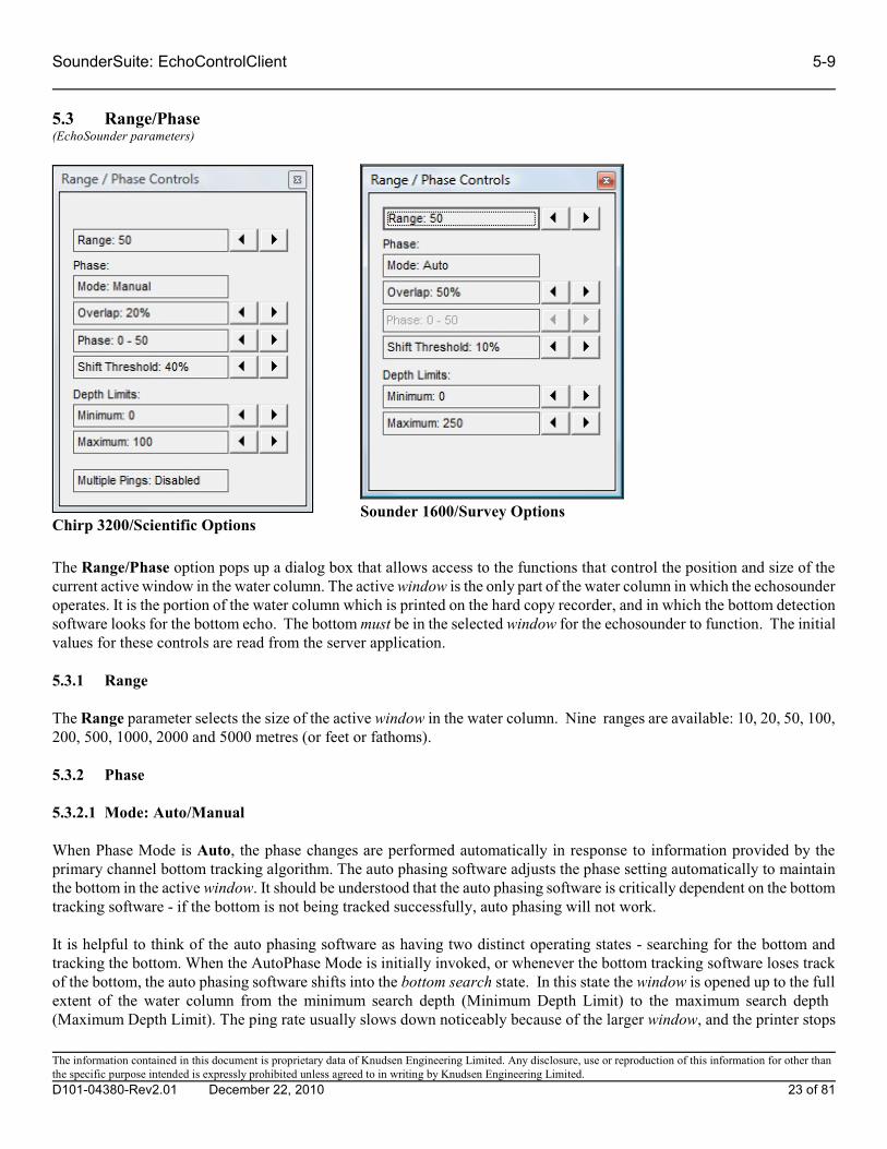
SounderSuite: EchoControlClient 5-9
5.3 Range/Phase(EchoSounder parameters)
The Range/Phase option pops up a dialog box that allows access to the functions that control the position and size of thecurrent active window in the water column. The active window is the only part of the water column in which the echosounderoperates. It is the portion of the water column which is printed on the hard copy recorder, and in which the bottom detectionsoftware looks for the bottom echo. The bottom must be in the selected window for the echosounder to function. The initialvalues for these controls are read from the server application.
5.3.1 Range
The Range parameter selects the size of the active window in the water column. Nine ranges are available: 10, 20, 50, 100,200, 500, 1000, 2000 and 5000 metres (or feet or fathoms).
5.3.2 Phase
5.3.2.1 Mode: Auto/Manual
When Phase Mode is Auto, the phase changes are performed automatically in response to information provided by theprimary channel bottom tracking algorithm. The auto phasing software adjusts the phase setting automatically to maintainthe bottom in the active window. It should be understood that the auto phasing software is critically dependent on the bottomtracking software - if the bottom is not being tracked successfully, auto phasing will not work.
It is helpful to think of the auto phasing software as having two distinct operating states - searching for the bottom andtracking the bottom. When the AutoPhase Mode is initially invoked, or whenever the bottom tracking software loses trackof the bottom, the auto phasing software shifts into the bottom search state. In this state the window is opened up to the fullextent of the water column from the minimum search depth (Minimum Depth Limit) to the maximum search depth (Maximum Depth Limit). The ping rate usually slows down noticeably because of the larger window, and the printer stops
Chirp 3200/Scientific OptionsSounder 1600/Survey Options
The information contained in this document is proprietary data of Knudsen Engineering Limited. Any disclosure, use or reproduction of this information for other thanthe specific purpose intended is expressly prohibited unless agreed to in writing by Knudsen Engineering Limited.
D101-04380-Rev2.01 December 22, 2010 23 of 81
5-10 SounderSuite: EchoControlClient
printing until the bottom is located. When the bottom is found, the auto phasing software selects the appropriate phase andshifts into the bottom tracking state.
Once the auto phasing software is in the bottom tracking state, it will continue to auto phase as long as the primary channelis being tracked successfully. It will re-enter the bottom search state if 5 consecutive samples are declared invalid by thebottom tracking software.
One other parameter is relevant to auto phasing operation - this is the Primary Channel, accessible through the Channelscontrol box, and described in Section 5.1.12. It specifies the channel which is used as the depth reference for phase changes.
5.3.2.1.1 Bottom Tracking
Although the bottom tracking process is operational at all times, it is discussed here because it becomes critically importantwhen auto phasing is enabled.
Locating and tracking the bottom is the most important software function performed by the echosounder. The term bottomtracking encompasses the process of identifying the bottom echo in the received acoustic signal, locating the precise leadingedge of the echo, computing the depth based on travel time and sound speed considerations, and most importantly, decidingwhether the result represents a valid depth measurement (it might be a fish, transducer ringing, reverberation, noise, or eventhe second echo from the previous ping). The decision must be made immediately, before sending the depth value to thedatalogger. The echosounder software, running in real time, does not have the luxury of looking ahead - it can only look backat previous depth samples. The algorithm used in the echosounder uses several previous samples, regardless of whether theywere determined at the time to be valid or not (the rationale for including invalid samples in the test is the fundamentaluncertainty in the validity designation). A variety of “least squares curve fitting” exercises is then carried out using the currentsample and all or some of the previous several samples. If at least one of the curves fits the data to within a user-specifiedtracking gate tolerance, the current sample is declared to be valid.
NOTE: Bottom tracking is performed independently for each channel. The depth value used by the auto phasing software isspecified by the Primary Channel parameter.
5.3.2.2 Overlap
The Phase Overlap is the overlap between successive Phases expressed as a percentage of the Range. For example, if theMinimum Depth Limit is set at 0 metres, the Maximum Depth Limit at 100 metres, the Range at 50 metres and Phase Overlapat 50%, possible phases are 0-50 metres, 25-75 metres and 50-100 metres. Each successive Phase overlaps the previous Phaseby 25 metres or 50% of the Range
5.3.2.3 Phase: Start - End Depths
The Phase parameter selects the depth, or location in the water column, of the active window (see explanation in Section5.3.2.1.1). The effect of the Phase parameter depends on the current Range setting. The standard echosounder softwareprovides a 50% overlap between Phase settings.
5.3.2.4 Shift Threshold
When the Phase Mode is set to Auto, the Phase will shift automatically when the detected depth reaches a certain threshold.The Phase will shift to the next shallower Phase when the Detected Depth reaches the top 10% of the current window. TheShift Threshold determines the point at which the system shifts to the next deepest phase. Available options are: 10, 20, 30,
The information contained in this document is proprietary data of Knudsen Engineering Limited. Any disclosure, use or reproduction of this information for other thanthe specific purpose intended is expressly prohibited unless agreed to in writing by Knudsen Engineering Limited.
D101-04380-Rev2.01 December 22, 2010 24 of 81

SounderSuite: EchoControlClient 5-11
40 and 50% of the current window. For example, if you have minimum and maximum Depth Limits of 0 and 100 metresrespectively, a Range of 50 metres and an Overlap of 50%, the valid Phases will be 0-50, 25-75 and 50-100 metres. If thecurrent Phase is 25-75 metres and the selected Shift Threshold is 30%, the Phase will shift to 0-50 metres when the DetectedDepth ascends to or above 30 metres (25 + 10% of 50 = 30). The Phase will shift to 50-100 metres when the Detected Depthdescends to or below 60 metres(75 - 30% of 50 = 60).
5.3.3 Depth Limits
5.3.3.1 Minimum
The Minimum Depth Limit parameter allows the user to adjust the minimum allowed depth toa value that is optimal for the current operating conditions and acquisition requirements. SeeSection 5.3.2.1 for the details regarding the use of this parameter.
NOTE: This limit is imposed for both autophase mode as well as manual phase mode. If thedepth ascends above this limit, proper bottom tracking will be lost.
5.3.3.2 Maximum
The Maximum Depth Limit parameter allows the user to adjust the maximum allowed depth toa value that is optimal for the current operating conditions and acquisition requirements. SeeSection 5.3.2.1 for the details regarding the use of this parameter.
NOTE: This limit is imposed for both autophase mode as well as manual phase mode. If thedepth descends below this limit, proper bottom tracking will be lost.
The information contained in this document is proprietary data of Knudsen Engineering Limited. Any disclosure, use or reproduction of this information for other thanthe specific purpose intended is expressly prohibited unless agreed to in writing by Knudsen Engineering Limited.
D101-04380-Rev2.01 December 22, 2010 25 of 81

5-12 SounderSuite: EchoControlClient
5.3.4 Multiple Pings (Chirp 3200/Scientific systems only)
For Chirp 3200 systems, there is a special operation mode for use in deep water conditions. This Multiple Pings mode allowsthe user to select a smaller window size, phased to the appropriate depth location and to use multiple pings within the watercolumn for faster data feedback. In normal operation, the ping rate of the sounder is dependent upon the maximum depth ofthe water column window being examined, which in deep water can be extremely slow. The Multiple Pings mode increasesthe ping rate at a specific time interval faster than normal operation and timed to allow the desired window to be receivedappropriately.
The information contained in this document is proprietary data of Knudsen Engineering Limited. Any disclosure, use or reproduction of this information for other thanthe specific purpose intended is expressly prohibited unless agreed to in writing by Knudsen Engineering Limited.
D101-04380-Rev2.01 December 22, 2010 26 of 81

SounderSuite: EchoControlClient 5-13
5.4 System(EchoSounder parameters)
The System Controls dialog provides access to system-wide parameters used by the echosounder. They are described below.
5.4.1 Working Units
The Working Units option allows the user to select the desired operating units from three options The operating Units canbe selected from Metres, Feet, and Fathoms. When these units are switched, the echosounder converts the speed of soundand draft to the appropriate new units.
The information contained in this document is proprietary data of Knudsen Engineering Limited. Any disclosure, use or reproduction of this information for other thanthe specific purpose intended is expressly prohibited unless agreed to in writing by Knudsen Engineering Limited.
D101-04380-Rev2.01 December 22, 2010 27 of 81

5-14 SounderSuite: EchoControlClient
5.4.2 Speed of Sound
This feature allows the adjustment of the velocity of sound value used by the echosounder for all depth calculations. The useradjusts this value in the course of a bar check, or enters the average expected velocity of sound over the water column ofinterest, obtained from a speed sensor.
The information contained in this document is proprietary data of Knudsen Engineering Limited. Any disclosure, use or reproduction of this information for other thanthe specific purpose intended is expressly prohibited unless agreed to in writing by Knudsen Engineering Limited.
D101-04380-Rev2.01 December 22, 2010 28 of 81

SounderSuite: EchoControlClient 5-15
5.4.3 Ping Rate
The EchoContolServer application controls the echosounder’s ping rate based on either range, the 1% duty cycle transmit limitation or the user-selected ping rate whichever is the largest value. The user can adjust this ping rate to the optimal valuefor his application. The echosounder will then ping at this rate if possible; built-in ping rate limitations may override the basicvalue selected here.
The information contained in this document is proprietary data of Knudsen Engineering Limited. Any disclosure, use or reproduction of this information for other thanthe specific purpose intended is expressly prohibited unless agreed to in writing by Knudsen Engineering Limited.
D101-04380-Rev2.01 December 22, 2010 29 of 81

5-16 SounderSuite: EchoControlClient
5.4.4 Tracking Gate
The tracking gate parameter is used by the bottom tracking algorithm to determine the validity of the current depth value. It is a depth variability tolerance value, defined as a distance above or below the bottom depth trend established by the currentand several previous samples. If the most recent depth value fits this established trend to within the range defined by thetracking gate, it is considered valid and is displayed in the appropriate dialog boxes. If a depth return falls outside of thisrange, it is deemed invalid and “0.0" is displayed in all the dialog boxes with depth displays.
For a discussion of the bottom tracking algorithm see Section 5.3.2.1.1.
5.4.5 Echogram: Heave Compensated/Uncompensated
When enabled (Heave Compensated), the echogram data is compensated for heave as detected by a heave sensor. Whendisabled, the echogram data is displayed as received.
5.4.6 Sync Mode: Internal/External
This switch specifies whether pings will be triggered internally (by the sounder module) or externally (by an external moduleconnected to the sounder unit through the Sync In connector, if applicable).
The information contained in this document is proprietary data of Knudsen Engineering Limited. Any disclosure, use or reproduction of this information for other thanthe specific purpose intended is expressly prohibited unless agreed to in writing by Knudsen Engineering Limited.
D101-04380-Rev2.01 December 22, 2010 30 of 81
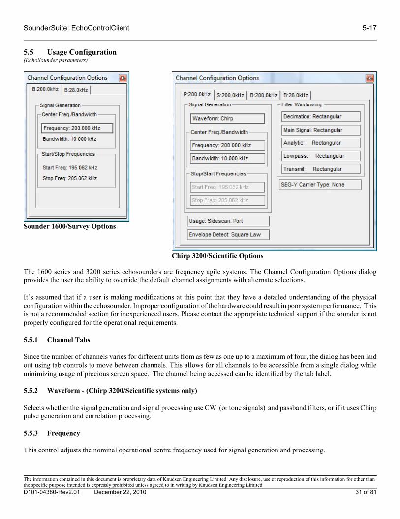
SounderSuite: EchoControlClient 5-17
5.5 Usage Configuration(EchoSounder parameters)
The 1600 series and 3200 series echosounders are frequency agile systems. The Channel Configuration Options dialogprovides the user the ability to override the default channel assignments with alternate selections.
It’s assumed that if a user is making modifications at this point that they have a detailed understanding of the physicalconfiguration within the echosounder. Improper configuration of the hardware could result in poor system performance. Thisis not a recommended section for inexperienced users. Please contact the appropriate technical support if the sounder is notproperly configured for the operational requirements.
5.5.1 Channel Tabs
Since the number of channels varies for different units from as few as one up to a maximum of four, the dialog has been laidout using tab controls to move between channels. This allows for all channels to be accessible from a single dialog whileminimizing usage of precious screen space. The channel being accessed can be identified by the tab label.
5.5.2 Waveform - (Chirp 3200/Scientific systems only)
Selects whether the signal generation and signal processing use CW (or tone signals) and passband filters, or if it uses Chirppulse generation and correlation processing.
5.5.3 Frequency
This control adjusts the nominal operational centre frequency used for signal generation and processing.
Chirp 3200/Scientific Options
Sounder 1600/Survey Options
The information contained in this document is proprietary data of Knudsen Engineering Limited. Any disclosure, use or reproduction of this information for other thanthe specific purpose intended is expressly prohibited unless agreed to in writing by Knudsen Engineering Limited.
D101-04380-Rev2.01 December 22, 2010 31 of 81

5-18 SounderSuite: EchoControlClient
5.5.4 Bandwidth - (Chirp 3200/Scientific systems only)
The user can adjust the bandwidth used for signal generation and processing.
5.5.5 Usage - (Chirp 3200/Scientific systems only)
The Usage option selects the operational mode of the channel. The operational mode determines where and how the echogramdata is displayed in the EchoControlClient application as well as what data file formats are available for recording. Currentlythere are three modes: bathymetry for downward looking channels used for depth detection and sub-bottom profile; SidescanPort for (as the name implies) the port channel of a sidescan configuration; and Sidescan starboard for the starboard channelof a sidescan configuration. Sidescan channels are displayed in the waterfall display mode section (scrolling top to bottom)with the port channel on the left half of the display region and the starboard channel on the right half of the display region. Bathymetry channels are displayed in the chart display section (scrolling right to left) in either overlayed presentation orstacked depending on the display mode setup.
5.5.6 Envelope Detect - (Chirp 3200/Scientific systems only)
There are two modes of envelope detection available on the Chirp 3200 series echosounders. The standard square-lawdetection mode improves the signal-to-noise ratio of the echogram data by helping to pull out the signal return level from thebackground noise. In some applications (sidescan and sub-bottom profiling) it may actually be of interest to see thebackground noise level. In these situations, the user can switch to the amplitude detection mode.
5.5.7 Filter Windowing - (Chirp 3200/Scientific systems only)
There are various digital filters applied through the signal processing code to extract and isolate the return echo from thebackground environmental noise. These digital filters can use various windowing options to enhance their filteringcharacteristics. The options available are: rectangular, hamming and cosine.
The main thing the user should watch, if he decides to adjust the windowing, is to use the same window type for the mainsignal filter and the transmit filter. This will ensure the best correlation results since the transmitted pulse will more closelymatch the anticipated correlation signal.
5.5.8 SEG-Y Carrier Type- (Chirp 3200/Scientific systems only)
The Chirp 3200/Scientific sounders are capable of providing what is termed as carrier data for recording into the industry-standard SEG-Y format. This data is available in three specific format types from a channel’s signal processing module.
Raw: This is the signed raw data as it is digitized at the A/D converter on the analog front end of the signalprocessing module. There is no filtering applied, other than a basic decimation filter.
Filtered: This the signed data after it has been through the digital correlation filter but before it has been envelopedetected. It will benefit from the pulse-compression characteristics of the chirp correlation filter, unlike theraw data.
Detected: This is the envelope detected data available at the original signal sampling rate, prior to being resampled tofit the fixed 1600 sample limitation of the KEB binary data.
The information contained in this document is proprietary data of Knudsen Engineering Limited. Any disclosure, use or reproduction of this information for other thanthe specific purpose intended is expressly prohibited unless agreed to in writing by Knudsen Engineering Limited.
D101-04380-Rev2.01 December 22, 2010 32 of 81

SounderSuite: EchoControlClient 5-19
5.6 Bar Check(EchoSounder parameters)
The Bar Check dialog box provides access to the primary calibration parameters required to perform a successful bar check.When Bar Check Mode On is selected, the echosounder is put into a specialized bar check mode. In this special mode, thedigitizer search window is centred on the specified Target Depth and is narrowed to the width of the specified Tracking Gate. When the Bar Check Mode On option is deselected, the echosounder deactivates the bar check mode and restores the standarddigitizer search window. If the Bar Check dialog is closed while the Bar Check Mode On is selected, the EchoControlapplication automatically deactivates the bar check mode in the echosounder.
For a description of typical bar check procedures, see D101-02251 Echosounder Concepts Technical Note.
5.6.1 Target Depth
The user adjusts this parameter to centre the digitizer search window around the expected depth of the test bar. The widthof the search window around this centre value is determined by the size of the tracking gate. The echosounder will digitizeon the strongest target that falls within this search window. If no target is found, any of the dialog boxes that display the depthwill indicate an invalid depth return.
5.6.2 Tracking Gate
The user adjusts the size of the tracking gate to define the width of the search window around the Target Depth value. Becausethe echosounder will digitize on the strongest target that falls within this search window, the tracking gate needs to beadjusted so that the real bottom will not fall within the search window. If the bar is close to the actual bottom location, makingthe Tracking Gate smaller allows the user to place the bar closer to the bottom than would be otherwise achievable.
The information contained in this document is proprietary data of Knudsen Engineering Limited. Any disclosure, use or reproduction of this information for other thanthe specific purpose intended is expressly prohibited unless agreed to in writing by Knudsen Engineering Limited.
D101-04380-Rev2.01 December 22, 2010 33 of 81

5-20 SounderSuite: EchoControlClient
5.6.3 Speed of SoundThis feature allows the adjustment of the velocity of sound value used by the echosounder for all depth calculations. The useradjusts this value in the course of a bar check, or enters the average expected velocity of sound over the water column ofinterest, obtained from a speed sensor
5.6.4 DraftDraft indicates the vertical distance from the surface of the water to the active face of the transducer. Its main use is to ensurethat the echosounder’s output is corrected for the transducer’s depth and inherent time delay. The draft can be setindependently for each of the available channels. Because the number of channels can vary from only one to as many as four, channel tabs are used to allow access to each channel’s draft within a single dialog reference.
5.6.5 Measured Depth
The Measured Depth is used as a feedback indicator while the user makes the adjustments during a bar check.
The information contained in this document is proprietary data of Knudsen Engineering Limited. Any disclosure, use or reproduction of this information for other thanthe specific purpose intended is expressly prohibited unless agreed to in writing by Knudsen Engineering Limited.
D101-04380-Rev2.01 December 22, 2010 34 of 81
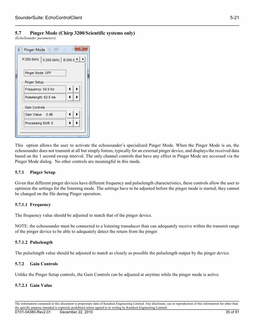
SounderSuite: EchoControlClient 5-21
5.7 Pinger Mode (Chirp 3200/Scientific systems only)(EchoSounder parameters)
This option allows the user to activate the echosounder’s specialized Pinger Mode. When the Pinger Mode is on, theechosounder does not transmit at all but simply listens, typically for an external pinger device, and displays the received databased on the 1 second sweep interval. The only channel controls that have any effect in Pinger Mode are accessed via thePinger Mode dialog. No other controls are meaningful in this mode.
5.7.1 Pinger Setup
Given that different pinger devices have different frequency and pulselength characteristics, these controls allow the user tooptimize the settings for the listening mode. The settings have to be adjusted before the pinger mode is started; they cannotbe changed on the file during Pinger operation.
5.7.1.1 Frequency
The frequency value should be adjusted to match that of the pinger device.
NOTE: the echosounder must be connected to a listening transducer than can adequately receive within the transmit rangeof the pinger device to be able to adequately detect the return from the pinger.
5.7.1.2 Pulselength
The pulselength value should be adjusted to match as closely as possible the pulselength output by the pinger device.
5.7.2 Gain Controls
Unlike the Pinger Setup controls, the Gain Controls can be adjusted at anytime while the pinger mode is active.
5.7.2.1 Gain Value
The information contained in this document is proprietary data of Knudsen Engineering Limited. Any disclosure, use or reproduction of this information for other thanthe specific purpose intended is expressly prohibited unless agreed to in writing by Knudsen Engineering Limited.
D101-04380-Rev2.01 December 22, 2010 35 of 81

5-22 SounderSuite: EchoControlClient
The Gain Value control adjusts the actual analog gain of the channel’s physical signal processing module. It is advisable toavoid adjusting this to too high a value as that may cause over driving of the analog front end. If the gain has been adjustedto approximate 40-50dB but weak signal quality remains, the user should try increasing the Processing Shift.
5.7.2.2 Processing Shift
The Processing Shift parameter is basically a scaling factor applied to the digital signal filters (digital gain). This factor canhelp to pull up otherwise weak and poor quality signals to a usable level.
The information contained in this document is proprietary data of Knudsen Engineering Limited. Any disclosure, use or reproduction of this information for other thanthe specific purpose intended is expressly prohibited unless agreed to in writing by Knudsen Engineering Limited.
D101-04380-Rev2.01 December 22, 2010 36 of 81
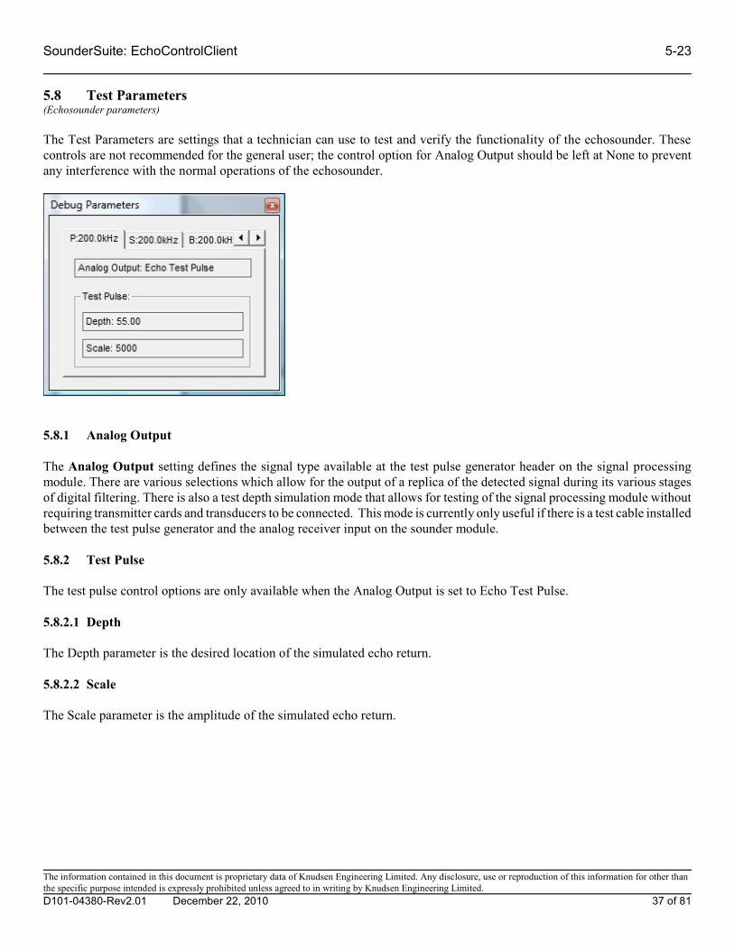
SounderSuite: EchoControlClient 5-23
5.8 Test Parameters(Echosounder parameters)
The Test Parameters are settings that a technician can use to test and verify the functionality of the echosounder. Thesecontrols are not recommended for the general user; the control option for Analog Output should be left at None to preventany interference with the normal operations of the echosounder.
5.8.1 Analog Output
The Analog Output setting defines the signal type available at the test pulse generator header on the signal processingmodule. There are various selections which allow for the output of a replica of the detected signal during its various stagesof digital filtering. There is also a test depth simulation mode that allows for testing of the signal processing module withoutrequiring transmitter cards and transducers to be connected. This mode is currently only useful if there is a test cable installedbetween the test pulse generator and the analog receiver input on the sounder module.
5.8.2 Test Pulse
The test pulse control options are only available when the Analog Output is set to Echo Test Pulse.
5.8.2.1 Depth
The Depth parameter is the desired location of the simulated echo return.
5.8.2.2 Scale
The Scale parameter is the amplitude of the simulated echo return.
The information contained in this document is proprietary data of Knudsen Engineering Limited. Any disclosure, use or reproduction of this information for other thanthe specific purpose intended is expressly prohibited unless agreed to in writing by Knudsen Engineering Limited.
D101-04380-Rev2.01 December 22, 2010 37 of 81

6-1 SounderSuite: EchoControlClient
6 MAIN MENU - View
6.1 Chart Display Setup(Application parameters)
There are up to four display modes available for data presentation. Any combination of these modes can be enabled to suitthe operational and data display requirements of the echosounder. One of these modes is the chart mode which displaysbathymetry data (downward looking channels) on a chart that scrolls from right to left. The Echogram Chart Setup providesaccess to controls that the user can use to customize the use and appearance of the chart mode.
NOTE: None of the display options adjustments will affect any of the recorded data. If the echogram data is being recordedto the binary file, the data is always stored in the same form it is received from the echosounder. All display transformationsare applied independently from the recorded data.
6.1.1 Status: Enabled/Disabled
The first button is a simple toggle for enabling or disabling the Chart mode display. For echosounders without anybathymetry channels (ie sidescan only), the Chart mode may not be desired at all. If the status is enabled, the Chart isdisplayed in the application’s main window. If no other modes are enabled, it will utilized the entire window display (seeFigure 6.0). If any other modes are enabled, it shares the window by displaying in an assigned portion of the display (seeFigure 2.1).
The information contained in this document is proprietary data of Knudsen Engineering Limited. Any disclosure, use or reproduction of this information for other thanthe specific purpose intended is expressly prohibited unless agreed to in writing by Knudsen Engineering Limited.
D101-04380-Rev2.01 December 22, 2010 38 of 81

SounderSuite: EchoControlClient 6-2
Figure 6.0: Main Application Window - Echogram Chart display only
6.1.2 Contrast
This option accesses the control that allows the user to increase/decrease the contrast of the displayed echogram data. Thismakes the data appear darker or lighter on the display without affecting the actual echogram data received from the sounder.
6.1.3 Display Mode
There are three display mode options available. 1. None turns the display off. No echogram or event data is displayed in this mode.2. Overlayed displays all bathymetry channels, overlayed together, using the entire chart display height.3. Stacked displays all bathymetry channels separately, with Channel 1 at the top and sequentially going down the
The information contained in this document is proprietary data of Knudsen Engineering Limited. Any disclosure, use or reproduction of this information for other thanthe specific purpose intended is expressly prohibited unless agreed to in writing by Knudsen Engineering Limited.
D101-04380-Rev2.01 December 22, 2010 39 of 81

6-3 SounderSuite: EchoControlClient
display.
6.1.4 Colour Mode
There are seven colour modes available, plus a simple greyscale mode. The seven colour modes are: Basic-Clr, Base-Red,Base-Green, Base-Blue, Base-Magenta, Base-Cyan, Base-Yellow. When the Base colour modes are used, the mostmeaningful presentation is achieved with the Background: Black selection. See Table 5.0 for details regarding echogram levelmapping.
6.1.5 Background: White/Black
When Background: Black is selected, the display colours are configured to make black the main background colour. Forboth colour and greyscale modes, the lowest level return is assigned the colour black. When Background: White is selected,the lowest level return is assigned the colour white or the primary colour of the Base colour mode (ie. Red for Base-Red)
Table 6.0: Colour Mode and Background combinations
Control Settings Display Colour Usage
Colour Mode Background Background colour Lowest level Highest level
Greyscale White White White Black
Black Black Black White
Basic - Clr* White White White Dark Red
Black Black Black Dark Red
Base - Red White White Red Black
Black Black Black Red
Base - Green White White Green Black
Black Black Black Green
Base - Blue White White Blue Black
Black Black Black Blue
Base - Magenta White White Magenta Black
Black Black Black Magenta
Base - Cyan White White Cyan Black
Black Black Black Cyan
Base - Yellow White White Yellow Black
Black Black Black Yellow
* The Basic-Clr actually uses the 15 basic Windows colours mapped from lowest level to highest level as follows: White orBlack (see table), Light Grey, Dark Grey, Cyan, Blue, Dark Blue, Dark Cyan, Dark Green, Dark Yellow, Green, Yellow,Magenta, Dark Magenta, Red, Dark Red. The other modes use a basic gradient from the lowest level colour to the highestlevel colour (see table).
The information contained in this document is proprietary data of Knudsen Engineering Limited. Any disclosure, use or reproduction of this information for other thanthe specific purpose intended is expressly prohibited unless agreed to in writing by Knudsen Engineering Limited.
D101-04380-Rev2.01 December 22, 2010 40 of 81

SounderSuite: EchoControlClient 6-4
6.1.6 Embedded Text: Enabled/Disabled
The Embedded Grid Text toggle allows the user to enable or disable the use of embedded grid text. The current grid scaleis always indicated in the scale block on the right side of the chart display. For additional information, the user can enableEmbedded Grid Text. This will result in grid text being displayed within the envelope data display whenever a range orphase change occurs, or at evenly spaced intervals if no changes have occurred. The embedded text can be disabled for caseswhen the grid text changes obscure the envelope data. The current scale will still be displayed in the right hand scale blockregardless of the status of this setting.
6.1.7 Grid Mode
There are times, such as when the chart display is sharing the window with the Oscilloscope display or when the applicationwindow is sized to a small area, that the grid information can overwhelm and obscure the echogram data of interest. The GridMode option allows the user to select between no grid, a coarse grid or a fine grid to best suit his display needs.
6.1.8 Overlays
In addition to the echogram data, other pertinent value may be plotted to the chart view including:
• Heave Indicator – records the heave values as received from a heave sensor• Heave Corrected Depth – records the detected depth corrected by the heave value• Uncorrected Depth – plots the detected depth value uncorrected by heave• Tracking Gate Limits – plots the upper and lower Tracking Gate Limits as lines parallel to the plotted depth• Tx Blanking – blanks any echogram data above the Tx Blanking value
The information contained in this document is proprietary data of Knudsen Engineering Limited. Any disclosure, use or reproduction of this information for other thanthe specific purpose intended is expressly prohibited unless agreed to in writing by Knudsen Engineering Limited.
D101-04380-Rev2.01 December 22, 2010 41 of 81

6-5 SounderSuite: EchoControlClient
6.2 Oscilloscope Setup(Application parameters)
As described in the previous sections for the other Chart Setups, there are up to four display modes available for datapresentation. Any combination of these modes can be enabled to suit the operational and data display requirements of theechosounder.
The Oscilloscope mode displays a “scope" trace that represents the signal return levels throughout the active window column.The scope grid maps amplitude from the bottom of the chart display to the top and time starting from the left increasing tothe right. This mode is typically useful for debug purposes or for those users interested in viewing signal characteristics.
NOTE: None of the display options adjustments will affect any of the recorded data. If the echogram data is being recordedto the binary file, the data is always stored in the same form it is received from the echosounder. All display transformationsare applied independently from the recorded data.
6.2.1 Status: Enabled/Disabled
The first button is a simple toggle for enabling or disabling the Waterfall mode display. For echosounders without anysidescan channels (ie bathymetry only), the Waterfall mode may not be desired at all. If the status is enabled, the Waterfallchart is displayed in the application’s main window. If no other modes are enabled, it will utilize the entire window display(see Figure 6.1). If any other modes are enabled, it shares the window by displaying in an assigned portion of the display (seeFigure 2.1).
The information contained in this document is proprietary data of Knudsen Engineering Limited. Any disclosure, use or reproduction of this information for other thanthe specific purpose intended is expressly prohibited unless agreed to in writing by Knudsen Engineering Limited.
D101-04380-Rev2.01 December 22, 2010 42 of 81

SounderSuite: EchoControlClient 6-6
Figure 6.1: Main Application Window - Oscilloscope display only
6.2.2 Scale Mode
The data presented in the scale block on the right side of the scope display can be adjusted to suit the users preferencebetween the following options: percentage, amplitude, or voltage.
6.2.3 Background: White/Black
When Background: Black is selected, the display colours are configured to make black the main background colour. Forboth colour and greyscale modes, the lowest level return is assigned the colour black. When Background: White is selected,the lowest level return is assigned the colour white.
The information contained in this document is proprietary data of Knudsen Engineering Limited. Any disclosure, use or reproduction of this information for other thanthe specific purpose intended is expressly prohibited unless agreed to in writing by Knudsen Engineering Limited.
D101-04380-Rev2.01 December 22, 2010 43 of 81

6-7 SounderSuite: EchoControlClient
6.2.4 Display Mode
There are three display mode options available.
1. None turns the display off. No echogram or event data is displayed in this mode.2. Stacked displays all channels separately, with Channel 1 at the top and sequentially going down the display.3. Single displays only one channel using the entire chart display height. The active channel is determined by the
selection in the Channel control.
6.2.5 Channel
The channel option is only available when the Display Mode is Single. The channel selection determines which channel'sdata gets displayed in the chart in Single Display Mode. A thermal recorder can be used for real-time hardcopy recording ofthe echogram data.
6.2.6 Grid Mode
There are times, such as when the oscilloscope display is sharing the window with the Chart display or when the applicationwindow is sized to a small area, that the grid information can overwhelm and obscure the echogram data of interest. The GridMode option allows the user to select between no grid, a coarse grid or a fine grid to best suit his display needs.
The information contained in this document is proprietary data of Knudsen Engineering Limited. Any disclosure, use or reproduction of this information for other thanthe specific purpose intended is expressly prohibited unless agreed to in writing by Knudsen Engineering Limited.
D101-04380-Rev2.01 December 22, 2010 44 of 81

SounderSuite: EchoControlClient 6-8
6.3 Waterfall Display Setup(Application parameters)
As described in the section for the Chart Display Setup, there are four display modes available for data presentation. Anycombination of these modes can be enabled to suit the operational and data display requirements of the echosounder.
The waterfall mode displays Sidescan data on a chart that scrolls from top to bottom. The port channel data is displayed onthe left half of the chart, and the starboard channel data is displayed on the right half of the chart.
The Waterfall Chart Setup provides access to controls to customize the use and appearance of the chart mode.
NOTE: None of the display options adjustments will affect any of the recorded data. If the echogram data is being recordedto the binary file, the data is always stored in the same form it is received from the echosounder. All display transformationsare applied independently from the recorded data.
6.3.1 Status: Enabled/Disabled
The first button is a simple toggle for enabling or disabling the Waterfall mode display. For echosounders without anysidescan channels (ie bathymetry only), the Waterfall mode may not be desired at all. If the status is enabled, the Waterfallchart is displayed in the application’s main window. If no other modes are enabled, it will utilized the entire window display(see Figure 6.2). If any other modes are enabled, it shares the window by displaying in an assigned portion of the display (seeFigure 2.1).
The information contained in this document is proprietary data of Knudsen Engineering Limited. Any disclosure, use or reproduction of this information for other thanthe specific purpose intended is expressly prohibited unless agreed to in writing by Knudsen Engineering Limited.
D101-04380-Rev2.01 December 22, 2010 45 of 81

6-9 SounderSuite: EchoControlClient
Figure 6.2: Main Application Window - Waterfall display only
6.3.2 Contrast
This option accesses the control that allows the user to increase/decrease the contrast of the displayed echogram data. Thismakes the data appear darker or lighter on the display without affecting the actual echogram data received from the sounder.
6.3.3 Display Mode
There are four display mode options available. 1. None turns the display off. No echogram or event data is displayed in this mode.2. Dual displays both port and starboard sidescan channels with the port channel on the left and the starboard channel
on the right.
The information contained in this document is proprietary data of Knudsen Engineering Limited. Any disclosure, use or reproduction of this information for other thanthe specific purpose intended is expressly prohibited unless agreed to in writing by Knudsen Engineering Limited.
D101-04380-Rev2.01 December 22, 2010 46 of 81

SounderSuite: EchoControlClient 6-10
3. Port displays the port sidescan channel only using the entire chart area available.4. Starboard displays the starboard sidescan channel only using the entire chart area available.
6.3.4 Colour Mode
There are seven colour modes available, plus a simple greyscale mode. The seven colour modes are: Basic-Clr, Base-Red,Base-Green, Base-Blue, Base-Magenta, Base-Cyan, Base-Yellow. When the Base colour modes are used, the mostmeaningful presentation is achieved with the Background: Black selection. See Table 6.0 for details regarding echogram levelmapping.
6.3.5 Background: White/Black
When Background: Black is selected, the display colours are configured to make black the main background colour. Forboth colour and greyscale modes, the lowest level return is assigned the colour black. When Background: White is selected,the lowest level return is assigned the colour white or the primary colour of the Base colour mode (ie. Red for Base-Red)
6.3.6 Embedded Text: Enabled/Disabled(not implemented at this time)
The Embedded Grid Text toggle allows the user to enable or disable the use of embedded grid text. The current grid scaleis always indicated in the scale block on the right side of the chart display. For additional information, the user can enableEmbedded Grid Text. This will result in grid text being displayed within the envelope data display whenever a range orphase change occurs, or at evenly spaced intervals if no changes have occurred. The embedded text can be disabled for caseswhen the grid text changes obscure the envelope data. The current scale will still be displayed in the right hand scale blockregardless of the status of this setting.
6.3.7 Grid Mode
There are times, such as when the chart display is sharing the window with the Oscilloscope display or when the applicationwindow is sized to a small area, that the grid information can overwhelm and obscure the echogram data of interest. The GridMode option allows the user to select between no grid, a coarse grid or a fine grid to best suit his display needs.
The information contained in this document is proprietary data of Knudsen Engineering Limited. Any disclosure, use or reproduction of this information for other thanthe specific purpose intended is expressly prohibited unless agreed to in writing by Knudsen Engineering Limited.
D101-04380-Rev2.01 December 22, 2010 47 of 81

6-11 SounderSuite: EchoControlClient
6.4 Carrier Display Setup (Chirp 3200/Advanced systems only)(Application parameters)
As described in the previous sections for the other display modes, there are up to four display modes available for datapresentation. Any combination of these modes can be enabled to suit the operational and data display requirements of theechosounder.
The Carrier Chart is only available on Chirp 3200/Scientific systems, and only if the SEG-Y carrier type is set to a formatother than None (see Section 5.5.8).
The Carrier Chart Setup provides access to controls to customize the use and appearance of the carrier chart mode.
NOTE: None of the display options adjustments will affect any of the recorded data. If the echogram data is being recordedto the binary file, the data is always stored in the same form it is received from the echosounder. All display transformationsare applied independently from the recorded data.
6.4.1 Status: Enabled/Disabled
The first button is a simple toggle for enabling or disabling the Carrier Chart mode display. If the status is enabled, theCarrier Chart is displayed in the application’s main window. If no other modes are enabled, it will utilized the entire windowdisplay (see Figure 6.3). If any other modes are enabled, it shares the window by displaying in an assigned portion of thedisplay (see Figure 2.1.)
The information contained in this document is proprietary data of Knudsen Engineering Limited. Any disclosure, use or reproduction of this information for other thanthe specific purpose intended is expressly prohibited unless agreed to in writing by Knudsen Engineering Limited.
D101-04380-Rev2.01 December 22, 2010 48 of 81
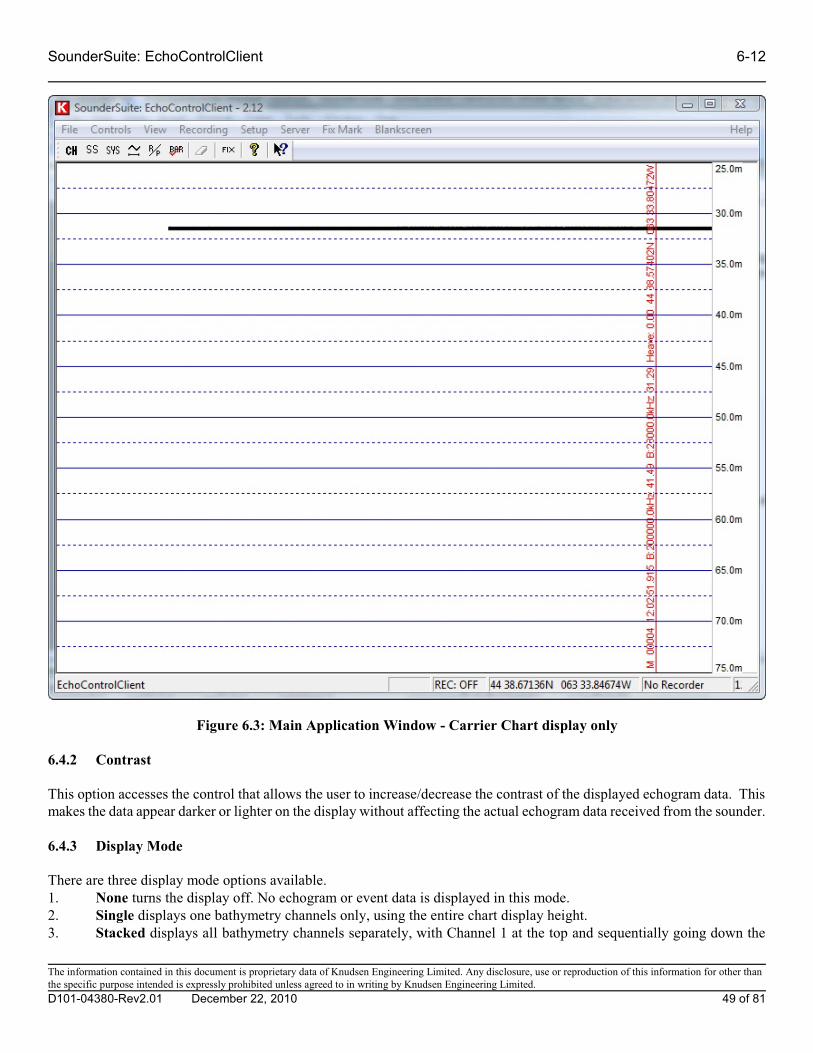
SounderSuite: EchoControlClient 6-12
Figure 6.3: Main Application Window - Carrier Chart display only
6.4.2 Contrast
This option accesses the control that allows the user to increase/decrease the contrast of the displayed echogram data. Thismakes the data appear darker or lighter on the display without affecting the actual echogram data received from the sounder.
6.4.3 Display Mode
There are three display mode options available. 1. None turns the display off. No echogram or event data is displayed in this mode.2. Single displays one bathymetry channels only, using the entire chart display height.3. Stacked displays all bathymetry channels separately, with Channel 1 at the top and sequentially going down the
The information contained in this document is proprietary data of Knudsen Engineering Limited. Any disclosure, use or reproduction of this information for other thanthe specific purpose intended is expressly prohibited unless agreed to in writing by Knudsen Engineering Limited.
D101-04380-Rev2.01 December 22, 2010 49 of 81

6-13 SounderSuite: EchoControlClient
display.
6.4.4 Channel
When the Display Mode is set to Single, the Channel control allows the user to select which of the available channels shouldbe displayed on the Carrier Chart.
6.4.5 Colour Mode
There are seven colour modes available, plus a simple greyscale mode. The seven colour modes are: Basic-Clr, Base-Red,Base-Green, Base-Blue, Base-Magenta, Base-Cyan, Base-Yellow. When the Base colour modes are used, the mostmeaningful presentation is achieved with the Background: Black selection. See Table 6.0 for details regarding echogram levelmapping.
6.4.6 Background: White/Black
When Background: Black is selected, the display colours are configured to make black the main background colour. Forboth colour and greyscale modes, the lowest level return is assigned the colour black. When Background: White is selected,the lowest level return is assigned the colour white or the primary colour of the Base colour mode (ie. Red for Base-Red)
6.4.7 Embedded Text: Enabled/Disabled
The Embedded Grid Text toggle allows the user to enable or disable the use of embedded grid text. The current grid scaleis always indicated in the scale block on the right side of the chart display. For additional information, the user can enableEmbedded Grid Text. This will result in grid text being displayed within the envelope data display whenever a range orphase change occurs, or at evenly spaced intervals if no changes have occurred. The embedded text can be disabled for caseswhen the grid text changes obscure the envelope data. The current scale will still be displayed in the right hand scale blockregardless of the status of this setting.
6.4.8 Grid Mode
There are times, such as when the chart display is sharing the window with the Oscilloscope display or when the applicationwindow is sized to a small area, that the grid information can overwhelm and obscure the echogram data of interest. The GridMode option allows the user to select between no grid, a coarse grid or a fine grid to best suit his display needs.
The information contained in this document is proprietary data of Knudsen Engineering Limited. Any disclosure, use or reproduction of this information for other thanthe specific purpose intended is expressly prohibited unless agreed to in writing by Knudsen Engineering Limited.
D101-04380-Rev2.01 December 22, 2010 50 of 81
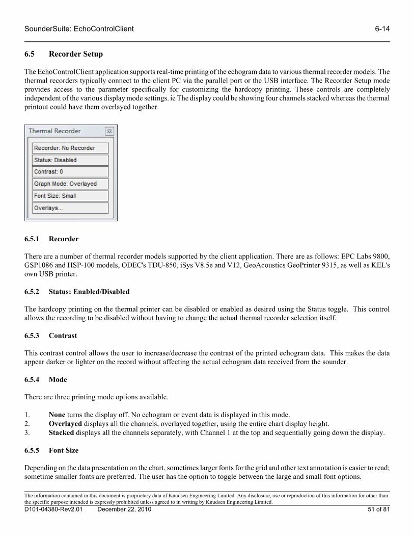
SounderSuite: EchoControlClient 6-14
6.5 Recorder Setup
The EchoControlClient application supports real-time printing of the echogram data to various thermal recorder models. Thethermal recorders typically connect to the client PC via the parallel port or the USB interface. The Recorder Setup modeprovides access to the parameter specifically for customizing the hardcopy printing. These controls are completelyindependent of the various display mode settings. ie The display could be showing four channels stacked whereas the thermalprintout could have them overlayed together.
6.5.1 Recorder
There are a number of thermal recorder models supported by the client application. There are as follows: EPC Labs 9800,GSP1086 and HSP-100 models, ODEC's TDU-850, iSys V8.5e and V12, GeoAcoustics GeoPrinter 9315, as well as KEL'sown USB printer.
6.5.2 Status: Enabled/Disabled
The hardcopy printing on the thermal printer can be disabled or enabled as desired using the Status toggle. This controlallows the recording to be disabled without having to change the actual thermal recorder selection itself.
6.5.3 Contrast
This contrast control allows the user to increase/decrease the contrast of the printed echogram data. This makes the dataappear darker or lighter on the record without affecting the actual echogram data received from the sounder.
6.5.4 Mode
There are three printing mode options available.
1. None turns the display off. No echogram or event data is displayed in this mode.2. Overlayed displays all the channels, overlayed together, using the entire chart display height.3. Stacked displays all the channels separately, with Channel 1 at the top and sequentially going down the display.
6.5.5 Font Size
Depending on the data presentation on the chart, sometimes larger fonts for the grid and other text annotation is easier to read;sometime smaller fonts are preferred. The user has the option to toggle between the large and small font options.
The information contained in this document is proprietary data of Knudsen Engineering Limited. Any disclosure, use or reproduction of this information for other thanthe specific purpose intended is expressly prohibited unless agreed to in writing by Knudsen Engineering Limited.
D101-04380-Rev2.01 December 22, 2010 51 of 81
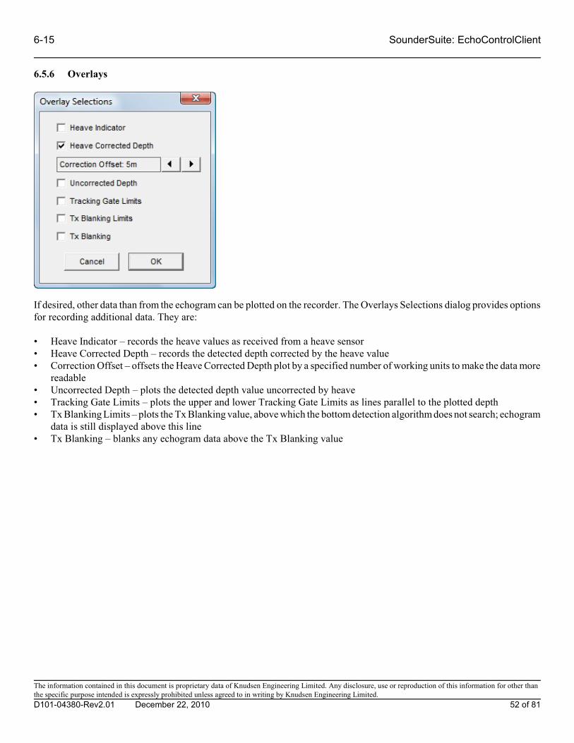
6-15 SounderSuite: EchoControlClient
6.5.6 Overlays
If desired, other data than from the echogram can be plotted on the recorder. The Overlays Selections dialog provides optionsfor recording additional data. They are:
• Heave Indicator – records the heave values as received from a heave sensor• Heave Corrected Depth – records the detected depth corrected by the heave value• Correction Offset – offsets the Heave Corrected Depth plot by a specified number of working units to make the data more
readable• Uncorrected Depth – plots the detected depth value uncorrected by heave• Tracking Gate Limits – plots the upper and lower Tracking Gate Limits as lines parallel to the plotted depth• Tx Blanking Limits – plots the Tx Blanking value, above which the bottom detection algorithm does not search; echogram
data is still displayed above this line• Tx Blanking – blanks any echogram data above the Tx Blanking value
The information contained in this document is proprietary data of Knudsen Engineering Limited. Any disclosure, use or reproduction of this information for other thanthe specific purpose intended is expressly prohibited unless agreed to in writing by Knudsen Engineering Limited.
D101-04380-Rev2.01 December 22, 2010 52 of 81

SounderSuite: EchoControlClient 6-16
6.6 Large Depths(Application parameters)
This option allows the user to enable a large digit depths display dialog box. This box uses a very large font for easierreadability from a distance. Displayed in the dialog are Channel Label, Channel Frequency and Depth. Channel Label andChannel Frequency are optional and can be hidden using option on the Preferences Menu.
The information contained in this document is proprietary data of Knudsen Engineering Limited. Any disclosure, use or reproduction of this information for other thanthe specific purpose intended is expressly prohibited unless agreed to in writing by Knudsen Engineering Limited.
D101-04380-Rev2.01 December 22, 2010 53 of 81

6-17 SounderSuite: EchoControlClient
6.7 Recording Status(Application parameters)
The Recording Status dialog displays the current status of any file recording that is active on the EchoControlClientapplication. It provides information regarding the file types being recorded, the storage path where they are recording, andthe name of any files currently open for recording. Clicking on any data display box in this dialog while the recording stateis inactive will activate the Configure Recording Options dialog (see Section 7.3).
When recording Seg-Y format files, depending on your configuration, multiple files may be recorded. If more than onechannel is recording Seg-Y data, the Recording Status dialog displays the number of channels. Clicking on the Seg-Y datadisplay box in this case brings up the Seg-Y Recording Status dialog. This dialog displays the names of all Seg-Y files beingrecorded. If only one channel is recording Seg-Y data, the filename is displayed on the Recording Status dialog in the samemanner as files of other formats.
The information contained in this document is proprietary data of Knudsen Engineering Limited. Any disclosure, use or reproduction of this information for other thanthe specific purpose intended is expressly prohibited unless agreed to in writing by Knudsen Engineering Limited.
D101-04380-Rev2.01 December 22, 2010 54 of 81

SounderSuite: EchoControlClient 6-18
6.8 Toolbar(Application parameters)
This control allows the user to enable and disable the application’s toolbar as desired. The toolbar is a “bar” located at thetop of the application’s window, just below the main menu bar. When active, it displays pushbutton controls that provideshortcuts to commonly used menu controls. When the toolbar is active, the effectively usable display area is decreased bythe amount used for the toolbar. Disabling the toolbar can give a slightly larger display area in the same size applicationwindow.
The control dialogs accessible via the toolbar are, from left to right: - Depth Channels (Section 5.1) - Sidescan Channels (Section 5.2) - System (Section 5.4) - Usage Configuration (Section 5.5) - Range/Phase (Section 5.3) - Bar Check (Section 5.6) - Blank Screen (Section 11) - Fix Mark (Section 10) - Help (Section 12) - Context-sensitive help (not implemented yet)
The information contained in this document is proprietary data of Knudsen Engineering Limited. Any disclosure, use or reproduction of this information for other thanthe specific purpose intended is expressly prohibited unless agreed to in writing by Knudsen Engineering Limited.
D101-04380-Rev2.01 December 22, 2010 55 of 81

6-19 SounderSuite: EchoControlClient
6.9 Status Bar(Application parameters)
This control allows the user to enable and disable the application’s status bar. The status bar is located at the bottom of theapplication’s window. The status bar provides helpful messages that describe menu controls, and other useful items. Thesemessages include, from left to right, if applicable:
- Menu help tips - Pinger distance measurement (Chirp 3200/scientific systems only) - Recording Status: REC: off for none, B for KEB, A for KEA, S for SEG-Y, and X for XTF - GPS position data (if GPS is connected and pinging is active) - Thermal recorder selection - PC time and date - Version of operating system detected.
The information contained in this document is proprietary data of Knudsen Engineering Limited. Any disclosure, use or reproduction of this information for other thanthe specific purpose intended is expressly prohibited unless agreed to in writing by Knudsen Engineering Limited.
D101-04380-Rev2.01 December 22, 2010 56 of 81

SounderSuite: EchoControlClient 6-20
6.10 Docking Bars
The user has the option to enable a mode for docking bars which places the Depth Channel, Sidescan Channels, Range/Phaseand System dialogs as docking dialog bars along the left-hand side of the main display window with a scrollbar at the far leftto access those controls that extend past the end of the active window. Disabling this option reverts the dialogs back toindependent free-floating dialog boxes that can be positioned anywhere on the user’s desktop.
The information contained in this document is proprietary data of Knudsen Engineering Limited. Any disclosure, use or reproduction of this information for other thanthe specific purpose intended is expressly prohibited unless agreed to in writing by Knudsen Engineering Limited.
D101-04380-Rev2.01 December 22, 2010 57 of 81
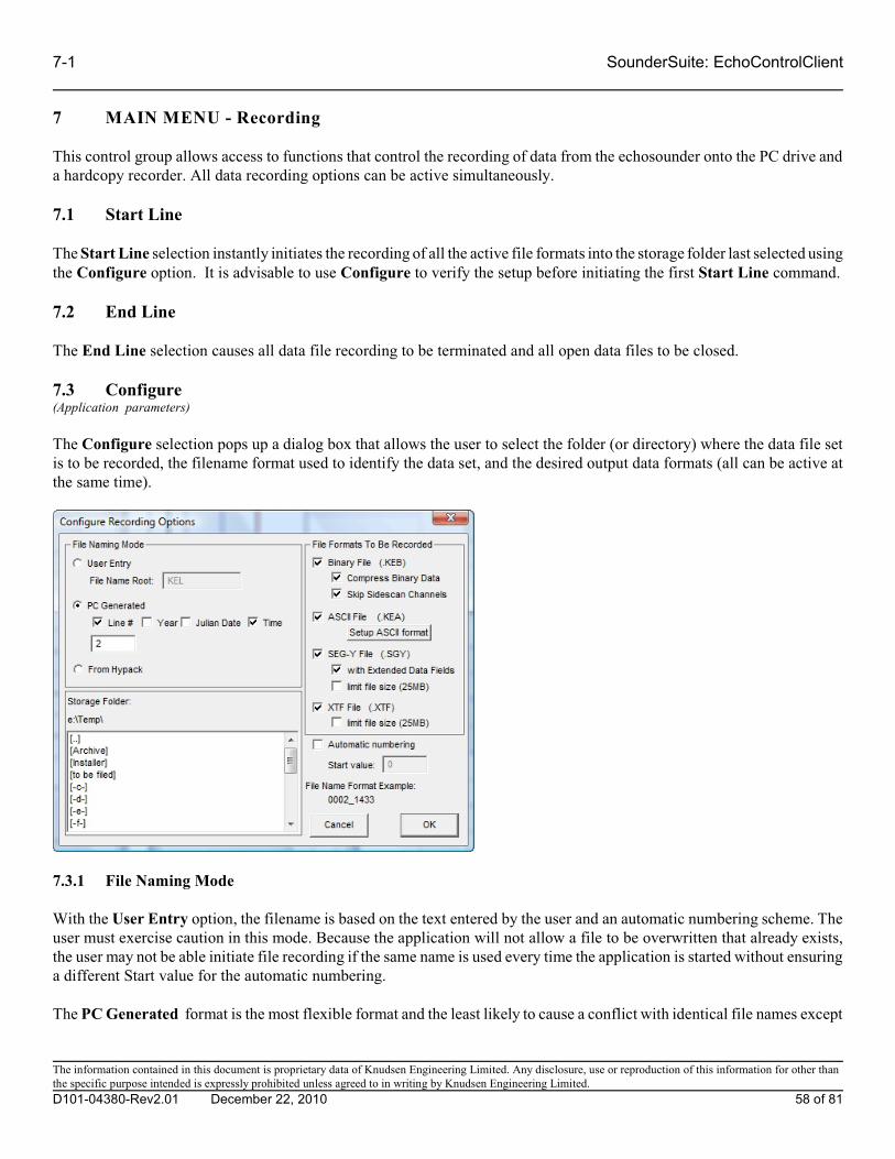
7-1 SounderSuite: EchoControlClient
7 MAIN MENU - Recording
This control group allows access to functions that control the recording of data from the echosounder onto the PC drive anda hardcopy recorder. All data recording options can be active simultaneously.
7.1 Start Line
The Start Line selection instantly initiates the recording of all the active file formats into the storage folder last selected usingthe Configure option. It is advisable to use Configure to verify the setup before initiating the first Start Line command.
7.2 End Line
The End Line selection causes all data file recording to be terminated and all open data files to be closed.
7.3 Configure(Application parameters)
The Configure selection pops up a dialog box that allows the user to select the folder (or directory) where the data file setis to be recorded, the filename format used to identify the data set, and the desired output data formats (all can be active atthe same time).
7.3.1 File Naming Mode
With the User Entry option, the filename is based on the text entered by the user and an automatic numbering scheme. Theuser must exercise caution in this mode. Because the application will not allow a file to be overwritten that already exists,the user may not be able initiate file recording if the same name is used every time the application is started without ensuringa different Start value for the automatic numbering.
The PC Generated format is the most flexible format and the least likely to cause a conflict with identical file names except
The information contained in this document is proprietary data of Knudsen Engineering Limited. Any disclosure, use or reproduction of this information for other thanthe specific purpose intended is expressly prohibited unless agreed to in writing by Knudsen Engineering Limited.
D101-04380-Rev2.01 December 22, 2010 58 of 81

SounderSuite: EchoControlClient 7-2
in the unlikely instance of two Start Lines within the same minute. If such a scenario happens frequently, the automaticnumbering option will help to prevent duplicate filenames.
From Hypack is only useful if the supporting Hypack DLL is being used to transfer data, file and line info from HypackInc.’s Hypack Survey application. When it is employed, the EchoControlClient application will start and stop recording whenHypack starts and stops logging, and will use the file folder and name root sent from Hypack.
7.3.2 Automatic Numbering
This mode is enabled by default when the User Entry filenaming mode is active. Basically, when this mode is active, thefilename is automatically appended with a number that starts at the value entered in the Start value box and automaticallyincrements every time one recording file is closed and a new one started. Enabling this mode helps to prevent recordingproblems that occur when a file already exists with a particular file name.
7.3.3 Storage Folder
To modify the Storage Folder selection, the user simply double-clicks on the [..] to back up from the current directory, ordouble-clicks on the new directory or drive name desired. The currently selected folder is displayed in the text line abovethe selection box.
7.3.4 File Formats To Be Recorded
There are four possible output file formats: Binary, SEG-Y, ASCII and XTF. The SEG-Y format is only available for 3200series systems using 32-bit processing modules. The XTF format is only available when there are sidescan channelsconfigured. The KEL proprietary formats, KEB and KEA, are always available. Any combination of available formats canbe recorded simultaneously.
7.3.4.1 Binary File Format (KEB)
The envelope data for each channel can be recorded in a binary data file for use by post-processing software. Every pingcycle, one record is stored with header information and raw data for each frequency channel. Each record is variable inlength, and may be compressed using a Huffman compression algorithm. The storage device for these files should havesufficient disk space free to store the vast amounts of data generated, especially when working in shallow water where thefaster ping rate results in a larger volume of data being generated.
See the File Format Specification KEB - D0 Format, Document # D101-04386 for complete formatting details
7.3.4.1.1 Compress Binary Data
When the Compress Binary Data box is checked, the application will compress all the KEB binary data records using aHuffman compression algorithm on each record. The File Type Id Preamble in each data file will indicate that Huffmancompression has been applied. This control gives the user the option to store in a compressed or uncompressed format.
7.3.4.1.2 Skip Sidescan Channels
When the Skip Sidescan Channels box is checked, the application will only record the Bathymetry channels to the KEBformat. The occasion when the user may want to select this is option is if the sidescan data is already being record into theXTF format and it is desired to save storage space.
The information contained in this document is proprietary data of Knudsen Engineering Limited. Any disclosure, use or reproduction of this information for other thanthe specific purpose intended is expressly prohibited unless agreed to in writing by Knudsen Engineering Limited.
D101-04380-Rev2.01 December 22, 2010 59 of 81

7-3 SounderSuite: EchoControlClient
7.3.4.2 ASCII File Format
The ASCII output file can be used to log many data fields such as depth, echosounder time, GPS position, and heave. Sincethese files do not contain any of the raw envelope data, they use substantially less disk space than the binary files. Every pingcycle, the application records one output string.
The user can request to modify the desired output data format by clicking on the Modify ASCII output format button. Thiscauses the application to pop up a configuration dialog box with selection options for the desired data fields.
7.3.4.2.1 Setup ASCII format
This dialog box allows the user to customize the ASCII file format string with certain limitations. The fields can only appearin the order listed (ie header string, HF depth, LF depth, checksum) separated only by commas (except hhmmss andmilliseconds), and terminated only at the very end by <CR>< LF>.
As various fields are selected or deselected, the Example String at the bottom of the dialog box changes to illustrate the
The information contained in this document is proprietary data of Knudsen Engineering Limited. Any disclosure, use or reproduction of this information for other thanthe specific purpose intended is expressly prohibited unless agreed to in writing by Knudsen Engineering Limited.
D101-04380-Rev2.01 December 22, 2010 60 of 81

SounderSuite: EchoControlClient 7-4
expected output format. It will only put the sample info for one channel’s worth of data. In the actual output file, for eachchannel present, its particular block of data fields is appended after the previous channel’s block.
Some fields can only be selected if other fields are also selected and will be inactive (greyed out) if the required field is notselected. For example, the Position Latency field is an active option only if the Position field is selected.
The format configuration selected is stored in the application’s registry keys and restored the next time the program isinvoked.
7.3.4.3 SEG-Y File Format
The SEG-Y output file format has been defined to meet as accurately as possible the Rev0 format specifications defined bythe Society of Exploration Geophysicists.
See the KEL SEGY FORMAT USAGE DEFINITION document, D101-03021, for complete formatting details.
7.3.4.3.1 SEG-Y Extended Data Fields
The original SEG-Y specification does not account for many useful data fields. If the user selects the option to include theextended data fields, numerous operation controls are recorded in the unassigned bytes at the end of the Rev0 Trace header. Some SEG-Y readers do not recognize files that contain data in these bytes so it is advisable to verify the requirements forthe desired reader application before selecting this option.
See the KEL SEGY FORMAT USAGE DEFINITION document, D101-03021, for complete formatting details.
7.3.4.3.2 Limit File Size (25MB)
When data is recorded over a long period of time, the resultant SEG-Y files using the standard 20000 ping limitation canbecome so large some readers encounter difficulties reading them for playback and processing. To protect against this typeof issue, the user can select the Limit File Size option to keep the files at a size usable by most SEG-Y readers.
7.3.4.4 XTF File Format
The XTF output file format is a specialized format used to record Sidescan and Bathymetry data. The format has been definedto be compatible with the standard as defined by Caris.
See the KEL XTF FORMAT USAGE DEFINITION document, D101-03322 for complete formatting details.
7.3.4.4.1 Limit File Size (25MB)
When data is recorded over a long period of time, the resultant XTF files using the standard 20000 ping limitation can becomeso large some readers encounter difficulties reading them for playback and processing. To protect against this type of issue,the user can select the Limit File Size option to keep the files at a size usable by most XTF readers.
The information contained in this document is proprietary data of Knudsen Engineering Limited. Any disclosure, use or reproduction of this information for other thanthe specific purpose intended is expressly prohibited unless agreed to in writing by Knudsen Engineering Limited.
D101-04380-Rev2.01 December 22, 2010 61 of 81
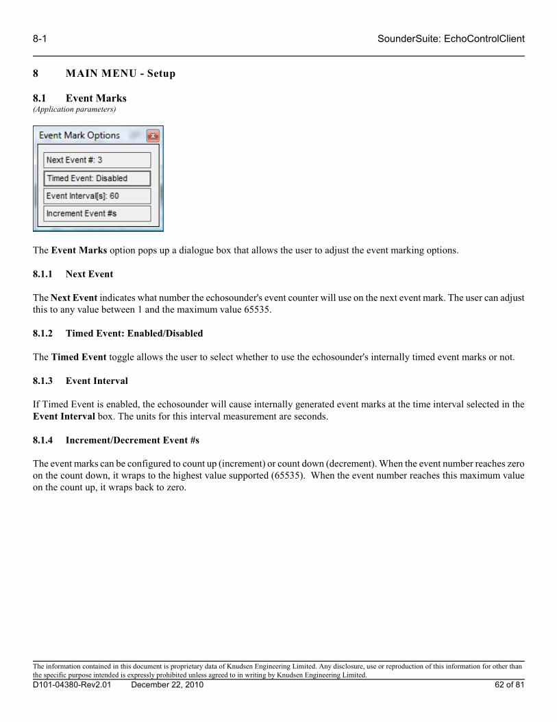
8-1 SounderSuite: EchoControlClient
8 MAIN MENU - Setup
8.1 Event Marks(Application parameters)
The Event Marks option pops up a dialogue box that allows the user to adjust the event marking options.
8.1.1 Next Event
The Next Event indicates what number the echosounder's event counter will use on the next event mark. The user can adjustthis to any value between 1 and the maximum value 65535.
8.1.2 Timed Event: Enabled/Disabled
The Timed Event toggle allows the user to select whether to use the echosounder's internally timed event marks or not.
8.1.3 Event Interval
If Timed Event is enabled, the echosounder will cause internally generated event marks at the time interval selected in theEvent Interval box. The units for this interval measurement are seconds.
8.1.4 Increment/Decrement Event #s
The event marks can be configured to count up (increment) or count down (decrement). When the event number reaches zeroon the count down, it wraps to the highest value supported (65535). When the event number reaches this maximum valueon the count up, it wraps back to zero.
The information contained in this document is proprietary data of Knudsen Engineering Limited. Any disclosure, use or reproduction of this information for other thanthe specific purpose intended is expressly prohibited unless agreed to in writing by Knudsen Engineering Limited.
D101-04380-Rev2.01 December 22, 2010 62 of 81

SounderSuite: EchoControlClient 8-2
8.2 Event Annotation(Application parameters)
This menu item brings up a dialog box that allows the user to select which of the available data parameters will be printedout on the event mark annotation line. The selections made here apply to the display and the thermal recorder output. Theuser has no control of the ordering of the parameters; they are output in the order they are listed if they are checked off.
The information contained in this document is proprietary data of Knudsen Engineering Limited. Any disclosure, use or reproduction of this information for other thanthe specific purpose intended is expressly prohibited unless agreed to in writing by Knudsen Engineering Limited.
D101-04380-Rev2.01 December 22, 2010 63 of 81

8-3 SounderSuite: EchoControlClient
8.3 Serial Devices (on Server)…(EchoSounder parameters)
8.3.1 Peripherals
While the peripheral devices connect to the server application on the host PC, the setup controls for these devices have beenincorporated into the client application. The dialog that appears when this menu option is selected is basically a status reportof detected com ports on the server and the current peripheral configuration.
At present, it simply assumes there may be as many as eight serial ports available on the host PC and it lists any device andcommunications settings currently in use . It is up to the user to know what serial ports are available on the host PC and wherethe particular peripherals of interest are connected. To add or modify any of the device settings, the user simply clicks theEdit box beside the desired COM port entry. This will bring up a dialog that provides access to the key settings required forconfiguring the port to accept data from the desired device.
8.3.1.1 Settings
The information contained in this document is proprietary data of Knudsen Engineering Limited. Any disclosure, use or reproduction of this information for other thanthe specific purpose intended is expressly prohibited unless agreed to in writing by Knudsen Engineering Limited.
D101-04380-Rev2.01 December 22, 2010 64 of 81

SounderSuite: EchoControlClient 8-4
8.3.1.1.1 Baud Rate
The baud rate can be adjusted to any one of the following options: 300, 600, 1200, 2400, 4800, 9600, 19200 and 38400.
8.3.1.1.2 Parity
All three options are available for parity: None, Even or Odd.
8.3.1.1.3 Data/Stop bits
There are two combinations of data and stop bits currently supported: 8 data /1 stop or 7 data/2 stop.
8.3.1.2 Format
There are a number of peripheral devices supported by the server drivers. These include:
GPS Receivers: NMEA: GGA, GLL, and GMPHeave Sensors: TSS1 and TSS3 formats, POSMV EM1000 and EM3000 formats, and Seatex: MRU
NOTE: The echosounder can support only one device of a particular type, such as one heave sensor or one GPS receiver. If one port has already been configured to a particular type of sensor, any attempt to configure another port to the same typeof sensor will fail. For example, if COM1 has been configured for TSS1 (a heave sensor format), COM2 cannot beconfigured for either TSS3 or Seatex: MRU (other heave sensor formats).
The information contained in this document is proprietary data of Knudsen Engineering Limited. Any disclosure, use or reproduction of this information for other thanthe specific purpose intended is expressly prohibited unless agreed to in writing by Knudsen Engineering Limited.
D101-04380-Rev2.01 December 22, 2010 65 of 81

8-5 SounderSuite: EchoControlClient
8.3.2 Data Logging
While the serial data logging is actually performed by server application on physical com port on the host PC, the setupcontrols for the data logging have been incorporated in the client application. The dialog that appears when this menu optionis selected is basically a status report of the detected com ports on the server and the current communications and data loggingconfiguration on these ports, if any.
At present, it simply assumes there may be as many as eight serial ports available on the host PC and it lists any data loggingformat and communications settings currently in use . It is up to the user to know what serial ports are available on the hostPC and where the datalogger systems are connected. To add or modify any of the device settings, the user simply clicks theFormat box beside the desired COM port entry. This will bring up a dialog that provides access to the key settings requiredfor configuring the port to accept data from the desired device.
8.3.2.1 Settings
The information contained in this document is proprietary data of Knudsen Engineering Limited. Any disclosure, use or reproduction of this information for other thanthe specific purpose intended is expressly prohibited unless agreed to in writing by Knudsen Engineering Limited.
D101-04380-Rev2.01 December 22, 2010 66 of 81

SounderSuite: EchoControlClient 8-6
8.3.2.1.1 Baud Rate
The baud rate can be adjusted to any one of the following options: 300, 600, 1200, 2400, 4800, 9600, 19200 and 38400.
8.3.2.1.2 Parity
All three options are available for parity: None, Even or Odd.
8.3.2.1.3 Data/Stop bits
There are two combinations of data and stop bits currently supported: 8 data /1 stop or 7 data/2 stop.
8.3.2.2 Format
There are various data logging output formats available ranging from a configurable user-defined format to industry standardprotocols. The standard formats have predefined field assignments that cannot be adapted by the user. The user-configurableformat can be customized, within certain limitations, to the user’s desired configuration.
The information contained in this document is proprietary data of Knudsen Engineering Limited. Any disclosure, use or reproduction of this information for other thanthe specific purpose intended is expressly prohibited unless agreed to in writing by Knudsen Engineering Limited.
D101-04380-Rev2.01 December 22, 2010 67 of 81
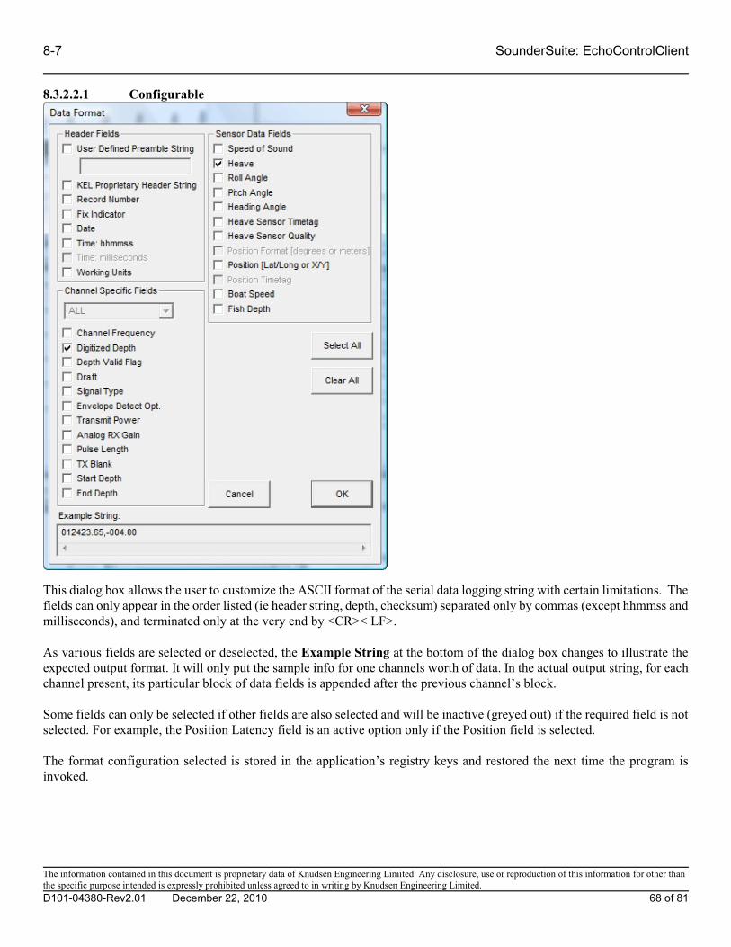
8-7 SounderSuite: EchoControlClient
8.3.2.2.1 Configurable
This dialog box allows the user to customize the ASCII format of the serial data logging string with certain limitations. Thefields can only appear in the order listed (ie header string, depth, checksum) separated only by commas (except hhmmss andmilliseconds), and terminated only at the very end by <CR>< LF>.
As various fields are selected or deselected, the Example String at the bottom of the dialog box changes to illustrate theexpected output format. It will only put the sample info for one channels worth of data. In the actual output string, for eachchannel present, its particular block of data fields is appended after the previous channel’s block.
Some fields can only be selected if other fields are also selected and will be inactive (greyed out) if the required field is notselected. For example, the Position Latency field is an active option only if the Position field is selected.
The format configuration selected is stored in the application’s registry keys and restored the next time the program isinvoked.
The information contained in this document is proprietary data of Knudsen Engineering Limited. Any disclosure, use or reproduction of this information for other thanthe specific purpose intended is expressly prohibited unless agreed to in writing by Knudsen Engineering Limited.
D101-04380-Rev2.01 December 22, 2010 68 of 81

SounderSuite: EchoControlClient 8-8
8.3.3 Hardware Add-ons (320M only)
While serial communications with hardware add-on devices is actually performed by the server application over the physicalcom port on the host PC, the setup controls for hardware add-ons have been incorporated in the client application. The dialogthat appears when this menu option is selected is basically a status report of the detected com ports on the server and thecurrent hardware add-ons configured on these ports, if any.
The 320M is the only hardware add-on currently supported by the EchoControl software. The Settings and Format buttonsoperate exactly as those previously described in the Peripherals and Data Logging sections. Note that the 320M front panelwill only operate correctly with a baud rate of 19200, no parity and 8 data bits/1 stop bit.
The information contained in this document is proprietary data of Knudsen Engineering Limited. Any disclosure, use or reproduction of this information for other thanthe specific purpose intended is expressly prohibited unless agreed to in writing by Knudsen Engineering Limited.
D101-04380-Rev2.01 December 22, 2010 69 of 81

8-9 SounderSuite: EchoControlClient
8.4 UDP Broadcast (on Server)…
The EchoControl software can transmit echogram data in ASCII format as UDP/IP datagrams. Selecting this menu optionbrings up the UDP Configuration dialog (figure 8.1). UDP transmission is performed by the server but configured throughthe client interface.
The UDP Configuration dialog shows the current UDP settings: IP address, UDP port number, transmission frequency andUDP message format. Clicking on the Settings button brings up the UDP Settings dialog to change these settings.
The IP address can be a broadcast address or single machine. Select the “Transmit at ping rate” option to send one UDPdatagram per ping. The Transmission rate can be specified when “Transmit at ping rate” is not selected. Available optionsare 1, 2, 4, 5 and 10Hz.
The information contained in this document is proprietary data of Knudsen Engineering Limited. Any disclosure, use or reproduction of this information for other thanthe specific purpose intended is expressly prohibited unless agreed to in writing by Knudsen Engineering Limited.
D101-04380-Rev2.01 December 22, 2010 70 of 81

SounderSuite: EchoControlClient 8-10
Clicking on the Format button brings up the UDP Message Format dialog. Available options are NONE, CONFIGURABLEand NAVY REMOTE. When “CONFIGURABLE” is selected, the Format... button will open the Data Format dialog asshown in Section 8.3.2.2. Virtually any combination of comma-separated values can be configured.
The information contained in this document is proprietary data of Knudsen Engineering Limited. Any disclosure, use or reproduction of this information for other thanthe specific purpose intended is expressly prohibited unless agreed to in writing by Knudsen Engineering Limited.
D101-04380-Rev2.01 December 22, 2010 71 of 81
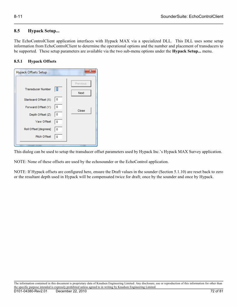
8-11 SounderSuite: EchoControlClient
8.5 Hypack Setup...
The EchoControlClient application interfaces with Hypack MAX via a specialized DLL. This DLL uses some setupinformation from EchoControlClient to determine the operational options and the number and placement of transducers tobe supported. These setup parameters are available via the two sub-menu options under the Hypack Setup... menu.
8.5.1 Hypack Offsets
This dialog can be used to setup the transducer offset parameters used by Hypack Inc.’s Hypack MAX Survey application.
NOTE: None of these offsets are used by the echosounder or the EchoControl application.
NOTE: If Hypack offsets are configured here, ensure the Draft values in the sounder (Section 5.1.10) are reset back to zeroor the resultant depth used in Hypack will be compensated twice for draft; once by the sounder and once by Hypack.
The information contained in this document is proprietary data of Knudsen Engineering Limited. Any disclosure, use or reproduction of this information for other thanthe specific purpose intended is expressly prohibited unless agreed to in writing by Knudsen Engineering Limited.
D101-04380-Rev2.01 December 22, 2010 72 of 81

SounderSuite: EchoControlClient 8-12
8.5.2 Hypack OpModes
The Hypack DLL has the ability to support a number of operational requirements. The setup for one user may not beappropriate for another user, so the EchoControlClient has been setup to provide the appropriate configuration based onfunctionality requirements and user preferences.
The Hypack DLL has the ability to display either ASCII printouts of the depth and heave data, or a grey scale presentationof the full echogram record. The user has the option to select the Survey Display mode most meaningful to them.
Hypack’s Single Beam Editor has the ability to take record echogram files (.BIN files) and use them for additional dataprocessing. For some users, this is a very desirable feature, but some users have no requirement to access and process thisdata. To avoid using valuable disk storage space for unnecessary data files, the BIN File Recording toggle allows the userto enable or disable the recording as desired.
Hypack has a Side Scan Survey function as well as the standard Survey function. When a sidescan transducer is employedwith the echosounder, enabling the Sidescan option enables the transfer of the necessary data from the standard Hypack DLL(EchoHypackDLL.dll) to Hypack’s Sidescan driver for waterfall display and data recording in Side Scan Survey.
The information contained in this document is proprietary data of Knudsen Engineering Limited. Any disclosure, use or reproduction of this information for other thanthe specific purpose intended is expressly prohibited unless agreed to in writing by Knudsen Engineering Limited.
D101-04380-Rev2.01 December 22, 2010 73 of 81

8-13 SounderSuite: EchoControlClient
8.6 Factory Defaults
Occasionally, after a software/firmware upgrade has been performed or a new site setup is required, it is advisable andconvenient to restore the sounder controls or the client display and recording controls back to factory default. This enablesstarting the sounder from a known default state. As discussed in Section 2.3, there are Echosounder controls and ApplicationControls. The reset commands for the Factory Defaults have been divided into two separate commands to allow the user todecide if he wants to reset the Echosounder or Application controls only, or if he wants to reset them all.
8.6.1 Display/Recording Controls
When the user selects the option to reset the Application display and recording controls, the client application will promptthe user for confirmation to proceed with the action. This prevents accidental modification of the settings when it may notbe desired.
8.6.2 EchoSounder Controls
When the user selects the option to reset the Echosounder controls, the client application will prompt the user for confirmationto proceed with the action. This prevents accidental modification of the settings when it may not be desired.
The information contained in this document is proprietary data of Knudsen Engineering Limited. Any disclosure, use or reproduction of this information for other thanthe specific purpose intended is expressly prohibited unless agreed to in writing by Knudsen Engineering Limited.
D101-04380-Rev2.01 December 22, 2010 74 of 81

SounderSuite: EchoControlClient 8-14
8.7 Preferences…
The Preferences... menu selection brings up the Preferences dialog. Selecting the “Continue sounder transmission aftershutdown” option allows pinging to continue after EchoControl Client has been shut down.
The information contained in this document is proprietary data of Knudsen Engineering Limited. Any disclosure, use or reproduction of this information for other thanthe specific purpose intended is expressly prohibited unless agreed to in writing by Knudsen Engineering Limited.
D101-04380-Rev2.01 December 22, 2010 75 of 81

9-1 SounderSuite: EchoControlClient
9 MAIN MENU - Server
Normally, the client application will make the TCP/IP communications connection to the server application at start upaccording to the configuration defined by the user. Sometimes if there are problems acquiring the communication, or if itwas desired to switch to another server connection, the additional Connect, Disconnect and Configure options can be usedto reacquire or redirect the communications link as desired.
9.1 Connect
The Connect option simply uses the connection setting defined at start-up or redefined using the Configure option to try toestablish the TCP/IP communications link. If the connection were to fail, then the Server Connection dialog will reappearto allow for modification to the settings and to allow the connection to be re-attempted. If the user chooses not to tryestablishing the connection (clicks Do Not Connect or the closing X) then access to key echosounder controls is disableduntil the connection can be reestablished.
9.2 Disconnect
The Disconnect option immediately terminates the TCP/IP communications link with the server. As long as the client isdisconnected, access to key echosounder controls is disabled.
9.3 Configure(Application parameters)
When the Configure option is selected, it activates the Server Connection dialog.
9.3.1 Server (name or IP address)
This edit control allows the user to enter the IP address or computer name of an echosounder host PC located somewhere onthe same network as the client application. The user may need to contact his system administrator to determine thisinformation. The server needs to be activated on the host PC to allow the client to connect properly except for the localcomputer option. If the local computer option is selected, the EchoControl Client application will attempt to start the serverapplication if it is not already active.
The information contained in this document is proprietary data of Knudsen Engineering Limited. Any disclosure, use or reproduction of this information for other thanthe specific purpose intended is expressly prohibited unless agreed to in writing by Knudsen Engineering Limited.
D101-04380-Rev2.01 December 22, 2010 76 of 81

SounderSuite: EchoControlClient 9-2
9.3.2 Previously used servers
This list box contains the history of any IP address or host names used for TCP/IP connection. By default, there is always anentry for 127.0.0.1 local computer (no network) to allow for a local-machine connection if the client is running on the samehost PC as the desired server. The user can select any of the previous host IDs for usage by simply clicking on the entry tohighlight it.
9.3.3 Connect/Do Not Connect
Once the appropriate server ID has been selected, the user can choose to either connect or not connect by clicking theappropriate button. If no server is connected, then access to key echosounder controls is disabled.
The information contained in this document is proprietary data of Knudsen Engineering Limited. Any disclosure, use or reproduction of this information for other thanthe specific purpose intended is expressly prohibited unless agreed to in writing by Knudsen Engineering Limited.
D101-04380-Rev2.01 December 22, 2010 77 of 81

10-1 SounderSuite: EchoControlClient
10 MAIN MENU - Fix Mark
The Fix Mark control is a special case menu item. It does not display any sub-menus, but causes an event mark when clicked. If there are no other dialog boxes active, simply pressing Alt-M will also cause a fix mark.
The information contained in this document is proprietary data of Knudsen Engineering Limited. Any disclosure, use or reproduction of this information for other thanthe specific purpose intended is expressly prohibited unless agreed to in writing by Knudsen Engineering Limited.
D101-04380-Rev2.01 December 22, 2010 78 of 81

SounderSuite: EchoControlClient 11-1
11 MAIN MENU - Blank Screen(not implemented at this time)
The Blank Screen control is another special case menu item. It does not display any sub-menus, but causes the greyscaledisplay window to be cleared of any data when clicked. If there are no other dialog boxes active, simply pressing Alt-B willcause the display to clear.
The information contained in this document is proprietary data of Knudsen Engineering Limited. Any disclosure, use or reproduction of this information for other thanthe specific purpose intended is expressly prohibited unless agreed to in writing by Knudsen Engineering Limited.
D101-04380-Rev2.01 December 22, 2010 79 of 81

12-1 SounderSuite: EchoControlClient
12 MAIN MENU - Help
The Help menu provides access to information dialogs that provide the user with system configuration information that ismost useful when contacting the factory for technical assistance. There are no other help features implemented at this time.
12.1 Sounder Info
When the server application starts, it scans the USB bus for all available KEL echosounder hardware modules and cataloguesa list of these modules. It uses the frequency and board serial number information for each module to sort and organize themodules sequentially by frequency (highest to lowest) and, if there are duplicate frequencies, by serial number (lowest tohighest). The Channel Mapping Assignments dialog provides a listing of this assignment list determined by the server.
The user can determine what physical modules were actually detected by clicking the Module Summary button.
12.1.1 Module Summary
The Module Summary dialog simply provides information regarding the hardware channels detected in the sounder by theserver application. For each hardware module, it reports the programmed serial number, the module’s type and its availablechannels, plus the firmware part number and version. This is a useful reference for verifying the hardware status in thesounder.
The information contained in this document is proprietary data of Knudsen Engineering Limited. Any disclosure, use or reproduction of this information for other thanthe specific purpose intended is expressly prohibited unless agreed to in writing by Knudsen Engineering Limited.
D101-04380-Rev2.01 December 22, 2010 80 of 81

SounderSuite: EchoControlClient 12-2
12.2 Tech Support
This option brings up a simple dialog box that provides contact information for technical support. It also provides informationabout the type of Windows operating system the EchoControlClient program has detected.
12.3 About EchoControlClient...
The About EchoControlClient... menu item brings up a simple dialog box stating the name of the PC software program, theKEL part number for the program, and the latest revision number.
The information contained in this document is proprietary data of Knudsen Engineering Limited. Any disclosure, use or reproduction of this information for other thanthe specific purpose intended is expressly prohibited unless agreed to in writing by Knudsen Engineering Limited.
D101-04380-Rev2.01 December 22, 2010 81 of 81

SounderSuite-USB
PostSurvey
Supports Software: D409-03171 V2.xx
D101-03175Revision 4.0July 6, 2009
Knudsen Engineering Limited10 Industrial Road
Perth, Ontario, Canada
T he information contained in this document is proprietary data of Knudsen Engineering Limited. Any disclosure, use or reproduction of this information for other than
the specific purpose intended is expressly prohibited unless agreed to in writing by Knudsen Engineering Limited.
D101-03175-Rev4.0 July 6, 2009 Page 2 of 23
CONTENTS
1 INTRODUCTION. . . . . . . . . . . . . . . . . . . . . . . . . . . . . . . . . . . . . . . . . . . . . . . . . . . . . . . . . . . . . . . . . . . . 1-1
1.1 About this manual. . . . . . . . . . . . . . . . . . . . . . . . . . . . . . . . . . . . . . . . . . . . . . . . . . . . . . . . . . . . . . 1-1
1.2 Software Description. . . . . . . . . . . . . . . . . . . . . . . . . . . . . . . . . . . . . . . . . . . . . . . . . . . . . . . . . . . . 1-1
1.3 Technical Support. . . . . . . . . . . . . . . . . . . . . . . . . . . . . . . . . . . . . . . . . . . . . . . . . . . . . . . . . . . . . . 1-1
2 OPERATING INSTRUCTIONS. . . . . . . . . . . . . . . . . . . . . . . . . . . . . . . . . . . . . . . . . . . . . . . . . . . . . . . . . . 2-1
2.1 Description. . . . . . . . . . . . . . . . . . . . . . . . . . . . . . . . . . . . . . . . . . . . . . . . . . . . . . . . . . . . . . . . . . . 2-1
3 File.. . . . . . . . . . . . . . . . . . . . . . . . . . . . . . . . . . . . . . . . . . . . . . . . . . . . . . . . . . . . . . . . . . . . . . . . . . . . . . 3-1
3.1 Open. . . . . . . . . . . . . . . . . . . . . . . . . . . . . . . . . . . . . . . . . . . . . . . . . . . . . . . . . . . . . . . . . . . . . . . 3-1
3.2 Close. . . . . . . . . . . . . . . . . . . . . . . . . . . . . . . . . . . . . . . . . . . . . . . . . . . . . . . . . . . . . . . . . . . . . . . 3-1
3.3 Copy to Clipboard. . . . . . . . . . . . . . . . . . . . . . . . . . . . . . . . . . . . . . . . . . . . . . . . . . . . . . . . . . . . . . 3-1
3.4 Save to Bitmap. . . . . . . . . . . . . . . . . . . . . . . . . . . . . . . . . . . . . . . . . . . . . . . . . . . . . . . . . . . . . . . . 3-1
3.5 Save Portion. . . . . . . . . . . . . . . . . . . . . . . . . . . . . . . . . . . . . . . . . . . . . . . . . . . . . . . . . . . . . . . . . . 3-1
3.6 ASCII Dump. . . . . . . . . . . . . . . . . . . . . . . . . . . . . . . . . . . . . . . . . . . . . . . . . . . . . . . . . . . . . . . . . . 3-2
3.7 Print. . . . . . . . . . . . . . . . . . . . . . . . . . . . . . . . . . . . . . . . . . . . . . . . . . . . . . . . . . . . . . . . . . . . . . . . 3-3
3.8 Print Preview. . . . . . . . . . . . . . . . . . . . . . . . . . . . . . . . . . . . . . . . . . . . . . . . . . . . . . . . . . . . . . . . . 3-4
3.9 Print Setup. . . . . . . . . . . . . . . . . . . . . . . . . . . . . . . . . . . . . . . . . . . . . . . . . . . . . . . . . . . . . . . . . . . 3-4
3.10 Thermal Recorder.... . . . . . . . . . . . . . . . . . . . . . . . . . . . . . . . . . . . . . . . . . . . . . . . . . . . . . . . . . . . . 3-4
3.10.1 Setup. . . . . . . . . . . . . . . . . . . . . . . . . . . . . . . . . . . . . . . . . . . . . . . . . . . . . . . . . . . . . . . . . 3-5
3.10.2 Send Data. . . . . . . . . . . . . . . . . . . . . . . . . . . . . . . . . . . . . . . . . . . . . . . . . . . . . . . . . . . . . . 3-6
3.11 Exit. . . . . . . . . . . . . . . . . . . . . . . . . . . . . . . . . . . . . . . . . . . . . . . . . . . . . . . . . . . . . . . . . . . . . . . . 3-6
4 View. . . . . . . . . . . . . . . . . . . . . . . . . . . . . . . . . . . . . . . . . . . . . . . . . . . . . . . . . . . . . . . . . . . . . . . . . . . . . 4-1
4.1 Channel Data. . . . . . . . . . . . . . . . . . . . . . . . . . . . . . . . . . . . . . . . . . . . . . . . . . . . . . . . . . . . . . . . . . 4-1
4.2 Parameter Data. . . . . . . . . . . . . . . . . . . . . . . . . . . . . . . . . . . . . . . . . . . . . . . . . . . . . . . . . . . . . . . . 4-2
4.3 Signal Data. . . . . . . . . . . . . . . . . . . . . . . . . . . . . . . . . . . . . . . . . . . . . . . . . . . . . . . . . . . . . . . . . . . 4-2
4.4 Depth Chart. . . . . . . . . . . . . . . . . . . . . . . . . . . . . . . . . . . . . . . . . . . . . . . . . . . . . . . . . . . . . . . . . . 4-3
4.5 Ping Chart.. . . . . . . . . . . . . . . . . . . . . . . . . . . . . . . . . . . . . . . . . . . . . . . . . . . . . . . . . . . . . . . . . . . 4-3
4.6 Status Bar. . . . . . . . . . . . . . . . . . . . . . . . . . . . . . . . . . . . . . . . . . . . . . . . . . . . . . . . . . . . . . . . . . . . 4-4
4.7 Main Toolbar.. . . . . . . . . . . . . . . . . . . . . . . . . . . . . . . . . . . . . . . . . . . . . . . . . . . . . . . . . . . . . . . . . 4-4
4.8 Info Toolbar. . . . . . . . . . . . . . . . . . . . . . . . . . . . . . . . . . . . . . . . . . . . . . . . . . . . . . . . . . . . . . . . . . 4-4
4.9 Settings Toolbar. . . . . . . . . . . . . . . . . . . . . . . . . . . . . . . . . . . . . . . . . . . . . . . . . . . . . . . . . . . . . . . 4-4
4.10 Channel Toolbar. . . . . . . . . . . . . . . . . . . . . . . . . . . . . . . . . . . . . . . . . . . . . . . . . . . . . . . . . . . . . . . 4-5
4.11 Active Global Scroll. . . . . . . . . . . . . . . . . . . . . . . . . . . . . . . . . . . . . . . . . . . . . . . . . . . . . . . . . . . . . 4-5
5 Settings. . . . . . . . . . . . . . . . . . . . . . . . . . . . . . . . . . . . . . . . . . . . . . . . . . . . . . . . . . . . . . . . . . . . . . . . . . . 5-1
5.1 Contrast. . . . . . . . . . . . . . . . . . . . . . . . . . . . . . . . . . . . . . . . . . . . . . . . . . . . . . . . . . . . . . . . . . . . . 5-1
5.2 Display. . . . . . . . . . . . . . . . . . . . . . . . . . . . . . . . . . . . . . . . . . . . . . . . . . . . . . . . . . . . . . . . . . . . . . 5-1
5.2.1 Colour. . . . . . . . . . . . . . . . . . . . . . . . . . . . . . . . . . . . . . . . . . . . . . . . . . . . . . . . . . . . . . . . 5-1
5.2.2 Reverse Colour. . . . . . . . . . . . . . . . . . . . . . . . . . . . . . . . . . . . . . . . . . . . . . . . . . . . . . . . . . 5-2
5.2.3 Digitized Line Display. . . . . . . . . . . . . . . . . . . . . . . . . . . . . . . . . . . . . . . . . . . . . . . . . . . . . . 5-2
5.2.4 Embedded Grid Text. . . . . . . . . . . . . . . . . . . . . . . . . . . . . . . . . . . . . . . . . . . . . . . . . . . . . . 5-2
5.2.5 Embedded Grid Lines. . . . . . . . . . . . . . . . . . . . . . . . . . . . . . . . . . . . . . . . . . . . . . . . . . . . . . 5-2
5.2.6 Reverse Display. . . . . . . . . . . . . . . . . . . . . . . . . . . . . . . . . . . . . . . . . . . . . . . . . . . . . . . . . . 5-2
5.2.7 Waterfall Display. . . . . . . . . . . . . . . . . . . . . . . . . . . . . . . . . . . . . . . . . . . . . . . . . . . . . . . . . 5-2
5.2.8 Zoom Display. . . . . . . . . . . . . . . . . . . . . . . . . . . . . . . . . . . . . . . . . . . . . . . . . . . . . . . . . . . 5-2
5.2.9 Text Size. . . . . . . . . . . . . . . . . . . . . . . . . . . . . . . . . . . . . . . . . . . . . . . . . . . . . . . . . . . . . . 5-2
5.3 Event Annotation. . . . . . . . . . . . . . . . . . . . . . . . . . . . . . . . . . . . . . . . . . . . . . . . . . . . . . . . . . . . . . . 5-3

T he information contained in this document is proprietary data of Knudsen Engineering Limited. Any disclosure, use or reproduction of this information for other than
the specific purpose intended is expressly prohibited unless agreed to in writing by Knudsen Engineering Limited.
D101-03175-Rev4.0 July 6, 2009 Page 3 of 23
5.4 Colour Selection. . . . . . . . . . . . . . . . . . . . . . . . . . . . . . . . . . . . . . . . . . . . . . . . . . . . . . . . . . . . . . . 5-3
5.5 Alternate Printer.. . . . . . . . . . . . . . . . . . . . . . . . . . . . . . . . . . . . . . . . . . . . . . . . . . . . . . . . . . . . . . . 5-4
6 Window. . . . . . . . . . . . . . . . . . . . . . . . . . . . . . . . . . . . . . . . . . . . . . . . . . . . . . . . . . . . . . . . . . . . . . . . . . . 6-1
6.1 Cascade. . . . . . . . . . . . . . . . . . . . . . . . . . . . . . . . . . . . . . . . . . . . . . . . . . . . . . . . . . . . . . . . . . . . . 6-1
6.2 Tile. . . . . . . . . . . . . . . . . . . . . . . . . . . . . . . . . . . . . . . . . . . . . . . . . . . . . . . . . . . . . . . . . . . . . . . . 6-1
6.3 Arrange Windows. . . . . . . . . . . . . . . . . . . . . . . . . . . . . . . . . . . . . . . . . . . . . . . . . . . . . . . . . . . . . . 6-1
7 Channel. . . . . . . . . . . . . . . . . . . . . . . . . . . . . . . . . . . . . . . . . . . . . . . . . . . . . . . . . . . . . . . . . . . . . . . . . . . 7-1
8 Help. . . . . . . . . . . . . . . . . . . . . . . . . . . . . . . . . . . . . . . . . . . . . . . . . . . . . . . . . . . . . . . . . . . . . . . . . . . . . . 8-1
8.1 About PostSurvey. . . . . . . . . . . . . . . . . . . . . . . . . . . . . . . . . . . . . . . . . . . . . . . . . . . . . . . . . . . . . . 8-1
8.2 Tech Support. . . . . . . . . . . . . . . . . . . . . . . . . . . . . . . . . . . . . . . . . . . . . . . . . . . . . . . . . . . . . . . . . 8-1
LIST OF TABLES
Table 3-1: Supported Thermal Recorders. . . . . . . . . . . . . . . . . . . . . . . . . . . . . . . . . . . . . . . . . . . . . . . . . . . . . . . . . . 3-5

1-1 SounderSuite-USB: PostSurvey
T he information contained in this document is proprietary data of Knudsen Engineering Limited. Any disclosure, use or reproduction of this information for other than
the specific purpose intended is expressly prohibited unless agreed to in writing by Knudsen Engineering Limited.
D101-03175-Rev4.0 July 6, 2009 Page 4 of 23
1 INTRODUCTION
1.1 About this manual
T his manual provides information about the Playback and Printing application, D409-03171, PostSurvey.exe. This program
has been designed to review previously recorded USB Echosounder data files and to produce hard copies on selected thermal
recorders and windows printers.
1.2 Software Description
T he US B Ec hos ounders developed and produced by Knudsen Engineering Limited were designed with a USB interface for
transferring detailed envelope data and parameter settings. PostSurvey is a specially designed Windows-compatible program
created to play back data records offline from the sounder and to create hard copy records. In addition to support for the
Knudsen Engineering Limited proprietary f ile format (KEB), this application also supports XTF and SEG-Y Rev.0 formats.
1.3 Technical Support
For technical support or to report problems please contact your local representative or:
Technical Support
Knudsen Engineering Limited
10 Industrial Road
Perth, Ontario
K7H 3P2
Voice: (613) 267-1165 8:30 am to 5:00 pm E.S.T. Core Hours
Fax: (613) 267-7085
E-Mail: [email protected]
WebSite: http://knudsenengineering.com/

SounderSuite-USB: PostSurvey 2-1
T he information contained in this document is proprietary data of Knudsen Engineering Limited. Any disclosure, use or reproduction of this information for other than
the specific purpose intended is expressly prohibited unless agreed to in writing by Knudsen Engineering Limited.
D101-03175-Rev4.0 July 6, 2009 Page 5 of 23
2 OPERATING INSTRUCTIONS
2.1 Description
The PostSurvey software is a multiple doc um ent interface Windows program design that provides the capability for data
playback and printing of multiple KEL Echosounder (KEB), XTF and SEG-Y data f iles on the PC. When the program is
invoked, it creates a window with three c ontrol groups offered on the main menu bar (with limited functionality), a blank
display area for greyscale or colour presentation of the echogram playback. Once a proper ly formatted KEB (D0, D1, D2
or D3 format), XTF or SEG-Y data file has been opened, an additional control group is added to the main menu bar and many
more options are added to the original control groups.
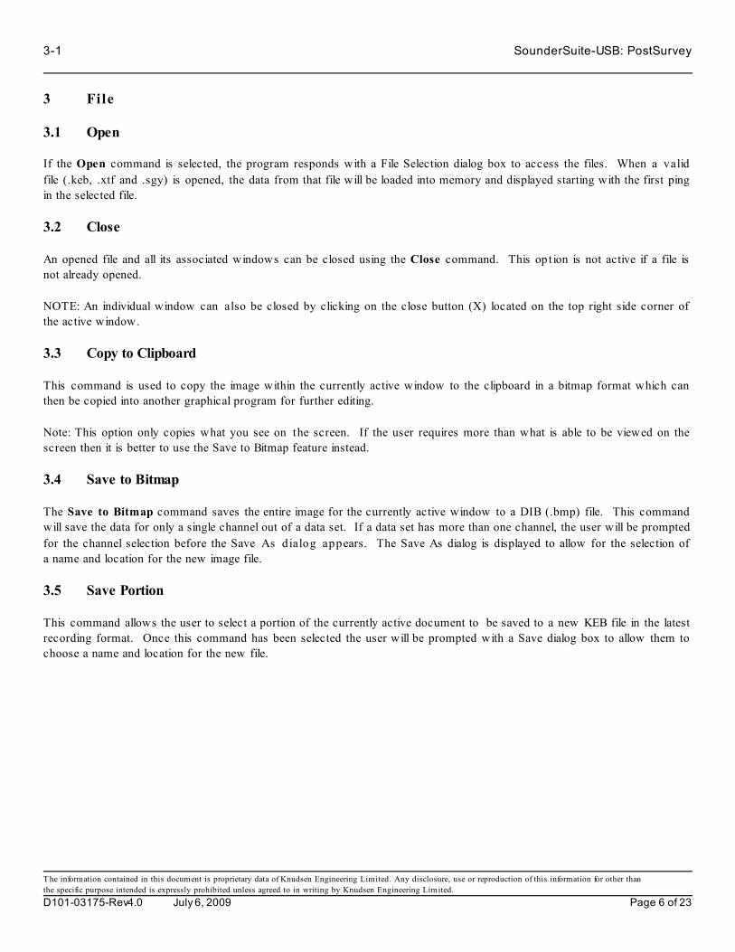
3-1 SounderSuite-USB: PostSurvey
T he information contained in this document is proprietary data of Knudsen Engineering Limited. Any disclosure, use or reproduction of this information for other than
the specific purpose intended is expressly prohibited unless agreed to in writing by Knudsen Engineering Limited.
D101-03175-Rev4.0 July 6, 2009 Page 6 of 23
3 File
3.1 Open
If the Open command is selected, the program responds with a File Selection dialog box to access the files. When a valid
file (.keb, .xtf and .sgy) is opened, the data from that file will be loaded into memory and displayed starting with the first ping
in the selected file.
3.2 Close
An opened file and all its associated windows can be closed using the Close command. This op tion is not active if a file is
not already opened.
NOTE: An individual window can also be closed by clicking on the close button (X) located on the top right side corner of
the active window.
3.3 Copy to Clipboard
This command is used to copy the image within the currently active window to the clipboard in a bitmap format which can
then be copied into another graphical program for further editing.
Note: This option only copies what you see on the screen. If the user requires more than what is able to be viewed on the
screen then it is better to use the Save to Bitmap feature instead.
3.4 Save to Bitmap
The Save to Bitmap command saves the entire image for the currently active window to a DIB (.bmp) file. This command
will save the data for only a single channel out of a data set. If a data set has more than one channel, the user will be prompted
for the channel selection before the Save As dialog appears. The Save As dialog is displayed to allow for the selection of
a name and location for the new image file.
3.5 Save Portion
This command allows the user to select a portion of the currently active document to be saved to a new KEB file in the latest
recording format. Once this command has been selected the user will be prompted with a Save dialog box to allow them to
choose a name and location for the new file.

SounderSuite-USB: PostSurvey 3-2
T he information contained in this document is proprietary data of Knudsen Engineering Limited. Any disclosure, use or reproduction of this information for other than
the specific purpose intended is expressly prohibited unless agreed to in writing by Knudsen Engineering Limited.
D101-03175-Rev4.0 July 6, 2009 Page 7 of 23
3.6 ASCII Dump
The ASCII Dump option will allow the user to select a variety of fields from the currently active data set that they would like
to record into a new standard ASCII file. The new file will have the extension .kea, however the user can select the name
and location through the standard Save As dialog box.

3-3 SounderSuite-USB: PostSurvey
T he information contained in this document is proprietary data of Knudsen Engineering Limited. Any disclosure, use or reproduction of this information for other than
the specific purpose intended is expressly prohibited unless agreed to in writing by Knudsen Engineering Limited.
D101-03175-Rev4.0 July 6, 2009 Page 8 of 23
3.7 Print
The Print option allows the user to print the entire data set or limited sections of the set to any Windows printer. This option
is only available if a valid KEB, XTF or SEG-Y Data file is opened.
When the Print opt ion is selected, depending on the file format of the currently active document the appropriate dialog box
pops up that allows the user to setup printout presentation options similar to the screen options: Greyscale/colour mode,
display mode, contrast (see Section 5 .2) . T he Print Range option provides the user with the ability to select the entire line
file set or only a section of the line file set to print. The pr intout c an be lim ited to print between Record Numbers or Fix
Numbers (if any exist).
Once the print options have been OK’d, the standard print dialog box appears. This allows the user access to the printer setup
to change from the current default printer, and to modify printer setup options. Once all the desired selections are made and
the us er c licks on OK, the printing will begin. Currently, any printer setup selections made for the current print job will be
lost on the next, and have to be re-selected.
NOTE: There is a Cancel Print capability but it has limited response capability once the printing proc edure has s tar ted.
Because the printouts are very graphically intensive and most systems print graphics quite slowly, the user should be certain
he really wants to proceed before clicking OK in the Print dialog box.

SounderSuite-USB: PostSurvey 3-4
T he information contained in this document is proprietary data of Knudsen Engineering Limited. Any disclosure, use or reproduction of this information for other than
the specific purpose intended is expressly prohibited unless agreed to in writing by Knudsen Engineering Limited.
D101-03175-Rev4.0 July 6, 2009 Page 9 of 23
NOTE: this menu option is only used to send data to s tandard Windows printers, not thermal recorders. Use the Thermal
Recorder: Send Data command to print to thermal recorders.
Important information: The printed envelope output is very graphically intensive. Some printers with on-board memory
may have problems with data overflow; reducing the print quality (resolution in dpi) may minimize this problem but it also
reduces the quality of the printout. Preliminary testing with a limited number of printers had the best presentat ional results
with the following printer setup options (click Setup in the Print dialog box to access): Landscape mode, Fine dithering, and
the highest resolution available to the printer (this is a printer specific option). For users of Windows 95/98, the spooler
options should be setup as follows to avoid creating excessively large temporary files (which can quickly over flow hard
drives with limited available space): printing should s tar t after the first page has spooled, and the spool data format should
be RAW not EMF. In some cases, it may even be better to disable spooling altogether and send the data directly to the printer.
3.8 Print Preview
This option is not fully implemented at this time.
3.9 Print Setup
This option is not fully implemented at this time.
3.10 Thermal Recorder...
This menu option provides access to two sub-menu items that allow the user to setup and send data to a thermal recorder. This
option is only available if a valid KEB data file is opened

3-5 SounderSuite-USB: PostSurvey
T he information contained in this document is proprietary data of Knudsen Engineering Limited. Any disclosure, use or reproduction of this information for other than
the specific purpose intended is expressly prohibited unless agreed to in writing by Knudsen Engineering Limited.
D101-03175-Rev4.0 July 6, 2009 Page 10 of 23
3.10.1 Setup
This option brings up a dialog box that allows the user to select a thermal recorder to be used for making hardcopies.
Table 3-1: Supported Thermal Recorders
Manufacturer Models
EPC Laboratories 9800, GSP-1086, HSP-100
ODEC TDU-850
iSys V8.5e, V12
GeoAcoustics 9315
The EPC GSP-1086 driver expects the user to have set the following parameters to the values listed via the unit’s front panel
menus:
DATA INPUT = PARALLEL
SWEEP = FORWARD
SHADES = 064
DATA TYPE = 6BITS
WIDTH = 2048
LPI = 200 nominal (not EXTERNAL )
The Port Addr option allows the user to specified the proper output port address for the printer port. For most systems, this
value should be 0378h, but for some laptops and secondary printer ports the alternate value of 0278h could be required.
The Print Test Block check box allows the user to tell the application to send some test data to the selected thermal recorder
to confirm it is interfaced properly. The test block consists of greyscale ramps with samples of im bedded grid and fix
annotation text.
The recorder selection and port address settings are stored in the application's registry keys and restored the next t ime the
program is invoked.

SounderSuite-USB: PostSurvey 3-6
T he information contained in this document is proprietary data of Knudsen Engineering Limited. Any disclosure, use or reproduction of this information for other than
the specific purpose intended is expressly prohibited unless agreed to in writing by Knudsen Engineering Limited.
D101-03175-Rev4.0 July 6, 2009 Page 11 of 23
3.10.2 Send Data
The Send Data menu option is used to print the entire file or selected portions for the currently active file. This option is not
available if a data file is not already opened. When this item is selected, it first causes a dialog box to pop up that allows the
user to select the presentational parameters desired. If the OK box is clicked, the application then brings up a status display
dialog box indicating the progress of the print job in terms of pings printed relative to the total number in the data set. It also
provides the user with the ability to cancel the print job if desired.
Note: this menu option is only used to send data to thermal recorders, not standard Windows printers. Use the Print command
to print to standard Windows printers.
3.11 Exit
The user can terminate the PostSurvey program using the Exit command. Many c onfiguration parameters are recorded as
the program is terminated.

4-1 SounderSuite-USB: PostSurvey
T he information contained in this document is proprietary data of Knudsen Engineering Limited. Any disclosure, use or reproduction of this information for other than
the specific purpose intended is expressly prohibited unless agreed to in writing by Knudsen Engineering Limited.
D101-03175-Rev4.0 July 6, 2009 Page 12 of 23
4 View
This control group provides access to data display dialogs and toolbar configurat ion c ontrols. The echogram chart is only
one of the items of interest during playback of the data set. Sometimes the user wishes to see what control settings were in
use to achieve the echogram on display. The various dialogs accessible from this control group provides access for the user
to this additional control information.
4.1 Channel Data
T hese Channel Data controls allow the user to display or close individual dialog boxes for each frequency channel. I f the
user clicks the lef t m ous e button while pointing the cursor to a position of interest on the echogram display window, any
active channel data dialog boxes will display the following data for the ping record represented by that point: record number
assigned by the echosounder, the depth and echo strength determined by the echosounder’s digitizer, and all of the transmit
power, gain, draft, transmit blanking, pulse type and signal type settings used for that particular ping cycle.

SounderSuite-USB: PostSurvey 4-2
T he information contained in this document is proprietary data of Knudsen Engineering Limited. Any disclosure, use or reproduction of this information for other than
the specific purpose intended is expressly prohibited unless agreed to in writing by Knudsen Engineering Limited.
D101-03175-Rev4.0 July 6, 2009 Page 13 of 23
4.2 Parameter Data
The Parameter Data option provides the us er with the ability to display or close a dialog box that presents the non-channel
specific data recorded from the echosounder. If the user clicks the left mouse button while pointing the cursor to a position
of interest on the echogram display window, the active parameter data dialog box will display the following data for the ping
record represented by that point: record number assigned by the echosounder, echosounder time stam p at s tart of the ping
cycle, w orking units and speed of sound being used for calculations, upper and lower limits of the active window being
displayed, fix status code and fix number if a fix condition exists, and the heave and position data used for the ping cycle.
4.3 Signal Data
The Signal Data option provides the user with the ability to display or close a dialog box that presents the extended channel -
specific and system data recorded from the echosounder. If the user clicks the left mouse button while pointing the cursor
to a position of interest on the echogram display window, the active parameter data dialog box will display the following data
for the ping record represented by that point: record number assigned by the echosounder, start and stop frequencies of the
transmit pulse, bandwidth of the transmit pulse, sample rate used to digitize the echogram, analog gain mode, and TVG mode

4-3 SounderSuite-USB: PostSurvey
T he information contained in this document is proprietary data of Knudsen Engineering Limited. Any disclosure, use or reproduction of this information for other than
the specific purpose intended is expressly prohibited unless agreed to in writing by Knudsen Engineering Limited.
D101-03175-Rev4.0 July 6, 2009 Page 14 of 23
in use for the ping record.
4.4 Depth Chart
This option allows the user to view the digitized depth value for the entire data set in a simple line c har t d is play. At the
bottom of this chart are located many VCR like controls which allow the user various options for viewing the Digitized depth
of the data set. Just under the display section of the graph is a parameter data section which displays the configuration
parameters for the right most ping if playing forward through the file or the left most ping if playing backwards through the
file. In order to close a particular chart you simply select the button that corresponds to the open chart along the Control Bar
on the left side of the screen.
4.5 Ping Chart
The Ping Chart operates in m uc h the same fashion as the Depth Chart, except the Ping Chart displays the intensity of each
sample along an entire ping trace. To the right of the graph is an intensity slider control which will magnify the image in the
display area by the factor displayed in the control. The VCR style controls operate in the same manner as those for the Depth
Chart.

SounderSuite-USB: PostSurvey 4-4
T he information contained in this document is proprietary data of Knudsen Engineering Limited. Any disclosure, use or reproduction of this information for other than
the specific purpose intended is expressly prohibited unless agreed to in writing by Knudsen Engineering Limited.
D101-03175-Rev4.0 July 6, 2009 Page 15 of 23
4.6 Status Bar
This control allows the user to enable and disable the application’s status bar.
The status bar contains relevant information such as the name of the currently active line file in the left corner. The Windows
Operating system is displayed in the box second f rom the right and the currently available thermal printer is displayed in the
box furthest to the right
4.7 Main Toolbar
This control allows the user to enable and disable the application’s Main tool bar.
The Main tool bar contains easy access controls which can also be found under the File Menu.
4.8 Info Toolbar
This control allows the user to enable and disable the application’s Info tool bar.
The Info tool bar contains easy access controls which can also be found under the view menu.
4.9 Settings Toolbar
This control allows the user to enable and disable the application’s Settings tool bar.
The Settings tool bar contains easy access controls which can also be found under the settings menu.

4-5 SounderSuite-USB: PostSurvey
T he information contained in this document is proprietary data of Knudsen Engineering Limited. Any disclosure, use or reproduction of this information for other than
the specific purpose intended is expressly prohibited unless agreed to in writing by Knudsen Engineering Limited.
D101-03175-Rev4.0 July 6, 2009 Page 16 of 23
4.10 Channel Toolbar
This control allows the user to enable and disable the application’s Channel toolbar.
The Channel tool bar contains one button which allows the user to select the channel within the currently active data set that
they would like to view. This tool bar is only active when more than one channel is recorded in the active data set.
4.11 Active Global Scroll
This control is a toggle that is only active if more than one channel is recorded in the currently active data set. Each channel
in a given data set will be opened in a separate window. When the Active Global Scroll toggle is set it acts as a master scroll
bar and will synchronize all open channel windows associated with the currently active data set.

SounderSuite-USB: PostSurvey 5-1
T he information contained in this document is proprietary data of Knudsen Engineering Limited. Any disclosure, use or reproduction of this information for other than
the specific purpose intended is expressly prohibited unless agreed to in writing by Knudsen Engineering Limited.
D101-03175-Rev4.0 July 6, 2009 Page 17 of 23
5 Settings
5.1 Contrast
This option pops up a dialog box with a single control that allows the user to increase/decrease the contrast of the displayed
greyscale data.
5.2 Display
The Display option brings up a dialog box that allows the user to customize the dis play presentation to a configuration that
suits his personal requirements.
5.2.1 Colour
When Colour mode is selected (box checked), the envelope data displayed in the program window is in 15 c olour levels,
mapped from lowest to highest levels as follows: White(normal video) or Black (reverse video), Light Grey, Dark Grey, Cyan,
Blue, Dark Blue, Dark Cyan, Dark Green, Dark Yellow, Green, Yellow, Magenta, Dark Magenta, Red, Dark Red. If this item
is not checked, the envelope data is displayed in levels of grey, where for normal video mode white is the lowest level return
and black is the highest; for reverse video mode white is the highest level return and black is the lowest.

5-2 SounderSuite-USB: PostSurvey
T he information contained in this document is proprietary data of Knudsen Engineering Limited. Any disclosure, use or reproduction of this information for other than
the specific purpose intended is expressly prohibited unless agreed to in writing by Knudsen Engineering Limited.
D101-03175-Rev4.0 July 6, 2009 Page 18 of 23
5.2.2 Reverse Colour
When Reverse Colour mode is selected, the display colours are configured to make black the main background colour. For
both colour and greyscale modes, the lowest level return is assigned the colour black. When Reverse Colour is not selected
(normal mode), the lowest level return is assigned the colour white.
5.2.3 Digitized Line Display
This control allows the user to display a red line over top of the echogram to indicate where the digitized depth was recorded
along the trace. This control acts as a toggle to allow the user to switch the Digitized depth overlay on or off.
5.2.4 Embedded Grid Text
The Embedded Grid Text option allows the us er to enable (box checked) or disable the use of embedded grid text. When
this option is enabled, grid text is d is played within the envelope data display whenever a range or phase change occurs, or
at evenly spaced intervals if no changes have occurred. The embedded text c an be disabled for cases when the grid text
changes obscure the envelope data.
5.2.5 Embedded Grid Lines
The Embedded Grid Lines option allows the user to enable (box checked) or disable the use of embedded grid lines. When
this option is enabled, the chart grid is displayed within the envelope data . The embedded grid lines can be disabled for cases
when it is undesirable such as bitmap creation for presentational purposes.
5.2.6 Reverse Display
This control will display the data set in Reverse View (last data sample displayed first). This control acts as a toggle to allow
the user to switch back to Normal View (first data sample displayed first).
5.2.7 Waterfall Display
This control will display the data set along the y axis. This control works as a toggle to allow the user to switch back to
standard view (display along the x axis).
5.2.8 Zoom Display
This control is a primitive zoom control w hich will magnify the display by a factor of 2 along which every axis is currently
active. This control acts as a toggle to allow the user the switch back to Regular view (1:1)
5.2.9 Text Size
This option allows the user to select a preferred font size.

SounderSuite-USB: PostSurvey 5-3
T he information contained in this document is proprietary data of Knudsen Engineering Limited. Any disclosure, use or reproduction of this information for other than
the specific purpose intended is expressly prohibited unless agreed to in writing by Knudsen Engineering Limited.
D101-03175-Rev4.0 July 6, 2009 Page 19 of 23
5.3 Event Annotation
This menu item brings up a dialog box that allows the user to select which of the available data parameter s w ill be printed
out on the event mark annotation line. The selections made here apply to the display, the Windows printer outputs, and the
thermal recorder output. The user has no control on the ordering of the parameters; they are output in the order they are listed
if they are checked off.
5.4 Colour Selection
The Colour Selection dialog box allows the user to customize the colour for select display c om ponents such as the grid,
annotation text, and overlays.

5-4 SounderSuite-USB: PostSurvey
T he information contained in this document is proprietary data of Knudsen Engineering Limited. Any disclosure, use or reproduction of this information for other than
the specific purpose intended is expressly prohibited unless agreed to in writing by Knudsen Engineering Limited.
D101-03175-Rev4.0 July 6, 2009 Page 20 of 23
5.5 Alternate Printer
This control is a toggle switch which was included for users having a problem printing to a select group of Windows printers.
The default for this control is unchecked. If the grid data for the line file being pr inted is the only data that is displayed on
a printout, then simply checking this control should resolve this problem.

SounderSuite-USB: PostSurvey 6-1
T he information contained in this document is proprietary data of Knudsen Engineering Limited. Any disclosure, use or reproduction of this information for other than
the specific purpose intended is expressly prohibited unless agreed to in writing by Knudsen Engineering Limited.
D101-03175-Rev4.0 July 6, 2009 Page 21 of 23
6 Window
This control group is only visible when a valid data file is opened.. This Control group allows the user to easily arrange the
multiple files and Windows they have open. At the bottom of this control group is a list of all open line files. When a line
file from this list is selected it then becomes the active file within the display area of the application.
6.1 Cascade
This option will take all open windows and display them in a overlapped format down the display area of the application.
6.2 Tile
This option w ill take all open windows and stretch them across the width of the display area and stack them on top of one
another.
6.3 Arrange Windows
This option will arrange all minimized file icons along the bottom of the display area within the application.

7-1 SounderSuite-USB: PostSurvey
T he information contained in this document is proprietary data of Knudsen Engineering Limited. Any disclosure, use or reproduction of this information for other than
the specific purpose intended is expressly prohibited unless agreed to in writing by Knudsen Engineering Limited.
D101-03175-Rev4.0 July 6, 2009 Page 22 of 23
7 Channel
The Channel menu item, and similarly, the Channel tool bar button provide access to a control dialog used to activate
additional channel windows for the currently active file set.
The Channel control is only active when more than one channel is recorded in the active data set.

SounderSuite-USB: PostSurvey 8-1
T he information contained in this document is proprietary data of Knudsen Engineering Limited. Any disclosure, use or reproduction of this information for other than
the specific purpose intended is expressly prohibited unless agreed to in writing by Knudsen Engineering Limited.
D101-03175-Rev4.0 July 6, 2009 Page 23 of 23
8 Help
8.1 About PostSurvey
The About PostSurvey... menu item brings up a simple dialog box s tating the name of the PC software program, the KEL
part number for the program, and the latest revision number.
8.2 Tech Support
This option brings up a simple dialog box that provides contact information for technical support. It also provides information
about the type of Windows operating system the program has detected.

SounderSuite -USB
Firmware Loader
Supports Software: D409-04363
D101-04382Revision 2.0July 6, 2009
Knudsen Engineering Limited10 Industrial Road
Perth, Ontario, Canada

T he information contained in this document is proprietary data of Knudsen Engineering Limited. Any disclosure, use or reproduction of this information for other than
the specific purpose intended is expressly prohibited unless agreed to in writing by Knudsen Engineering Limited.
D101-04382-Rev2.0 July 6, 2009Page 2 of 17
CONTENTS
1 INTRODUCTION. . . . . . . . . . . . . . . . . . . . . . . . . . . . . . . . . . . . . . . . . . . . . . . . . . . . . . . . . . . . . . . . . . . . 1-1
1.1 About this manual. . . . . . . . . . . . . . . . . . . . . . . . . . . . . . . . . . . . . . . . . . . . . . . . . . . . . . . . . . . . . . 1-1
1.2 Software Description. . . . . . . . . . . . . . . . . . . . . . . . . . . . . . . . . . . . . . . . . . . . . . . . . . . . . . . . . . . . 1-1
1.3 Technical Support. . . . . . . . . . . . . . . . . . . . . . . . . . . . . . . . . . . . . . . . . . . . . . . . . . . . . . . . . . . . . . 1-1
2 OPERATING INSTRUCTIONS. . . . . . . . . . . . . . . . . . . . . . . . . . . . . . . . . . . . . . . . . . . . . . . . . . . . . . . . . . 2-1
2.1 Description. . . . . . . . . . . . . . . . . . . . . . . . . . . . . . . . . . . . . . . . . . . . . . . . . . . . . . . . . . . . . . . . . . . 2-1
2.2 System. . . . . . . . . . . . . . . . . . . . . . . . . . . . . . . . . . . . . . . . . . . . . . . . . . . . . . . . . . . . . . . . . . . . . . 2-2
2.2.1 Scan for Devices. . . . . . . . . . . . . . . . . . . . . . . . . . . . . . . . . . . . . . . . . . . . . . . . . . . . . . . . . 2-2
2.2.2 Exit. . . . . . . . . . . . . . . . . . . . . . . . . . . . . . . . . . . . . . . . . . . . . . . . . . . . . . . . . . . . . . . . . . 2-2
2.3 View. . . . . . . . . . . . . . . . . . . . . . . . . . . . . . . . . . . . . . . . . . . . . . . . . . . . . . . . . . . . . . . . . . . . . . . 2-2
2.3.1 Load DSP Firmware. . . . . . . . . . . . . . . . . . . . . . . . . . . . . . . . . . . . . . . . . . . . . . . . . . . . . . 2-2
2.3.2 Load CFG Update. . . . . . . . . . . . . . . . . . . . . . . . . . . . . . . . . . . . . . . . . . . . . . . . . . . . . . . . 2-6
2.3.3 Load Printer Firmware. . . . . . . . . . . . . . . . . . . . . . . . . . . . . . . . . . . . . . . . . . . . . . . . . . . . . 2-9
2.4 Help. . . . . . . . . . . . . . . . . . . . . . . . . . . . . . . . . . . . . . . . . . . . . . . . . . . . . . . . . . . . . . . . . . . . . . . 2-12
2.4.1 Sounder Info. . . . . . . . . . . . . . . . . . . . . . . . . . . . . . . . . . . . . . . . . . . . . . . . . . . . . . . . . . . 2-12
2.4.2 Tech Support. . . . . . . . . . . . . . . . . . . . . . . . . . . . . . . . . . . . . . . . . . . . . . . . . . . . . . . . . . 2-14
2.4.3 About FirmwareLoader.... . . . . . . . . . . . . . . . . . . . . . . . . . . . . . . . . . . . . . . . . . . . . . . . . . 2-14

SounderSuite: FirmwareLoader 1-1
T he information contained in this document is proprietary data of Knudsen Engineering Limited. Any disclosure, use or reproduction of this information for other than
the specific purpose intended is expressly prohibited unless agreed to in writing by Knudsen Engineering Limited.
D101-04382-Rev2.0 July 6, 2009Page 3 of 17
1 INTRODUCTION
1.1 About this manual
T his manual provides information about the Firmware Loader application, D409-04363, FirmwareLoader.exe. This program
has been designed to s uppor t in-field firmware upgrades of the internal modules of Knudsen Engineering Limited’s USB
Echosounders. For detailed instructions on the upgrade process, please see document reference D101-04383: Windows
Installation and Firmware Upgrades.
1.2 Software Description
The Firmware Loader allows the user in the field to upgrade the firmware in his unit’s channel DSP modules and printer
module (if one is present). This application provides the user access to controls to program the firmware with new releases
from the factory for overall operational enhancements. Additionally, it allows the user to program configuration information
supplied by the factory and granted to licenced users.
1.3 Technical Support
For technical support or to report problems please contact your local representative or:
Technical Support
Knudsen Engineering Limited
10 Industrial Road
Perth, Ontario
K7H 3P2
Voice: (613) 267-1165 8:30 am to 5:00 pm E.S.T. Core Hours
Fax: (613) 267-7085
E-Mail: [email protected]
WebSite: http://knudsenengineering.com/
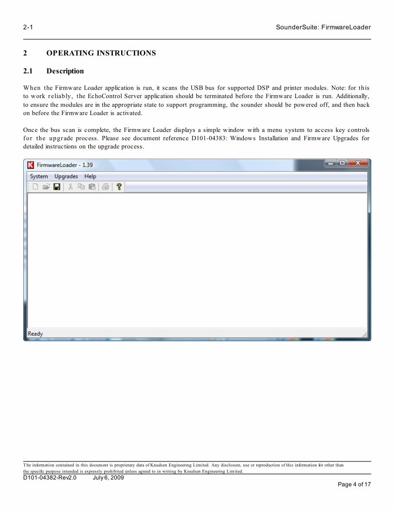
2-1 SounderSuite: FirmwareLoader
T he information contained in this document is proprietary data of Knudsen Engineering Limited. Any disclosure, use or reproduction of this information for other than
the specific purpose intended is expressly prohibited unless agreed to in writing by Knudsen Engineering Limited.
D101-04382-Rev2.0 July 6, 2009Page 4 of 17
2 OPERATING INSTRUCTIONS
2.1 Description
When the Firmware Loader application is run, it scans the USB bus for supported DSP and printer modules. Note: for th is
to work r eliably, the EchoControl Server application should be terminated before the Firmware Loader is run. Additionally,
to ensure the modules are in the appropriate state to support programming, the sounder should be powered off, and then back
on before the Firmware Loader is activated.
Once the bus scan is complete, the Firmware Loader displays a simple window with a menu s ystem to access key controls
for the upgrade process. Please see document reference D101-04383: Windows Installation and Firmware Upgrades for
detailed instructions on the upgrade process.

SounderSuite: FirmwareLoader 2-2
T he information contained in this document is proprietary data of Knudsen Engineering Limited. Any disclosure, use or reproduction of this information for other than
the specific purpose intended is expressly prohibited unless agreed to in writing by Knudsen Engineering Limited.
D101-04382-Rev2.0 July 6, 2009Page 5 of 17
2.2 System
2.2.1 Scan for Devices
Sometimes on start-up, the Firmware Loader may not see any DSP or printer modules on the bus. For example, if they are
not connected or are powered off. This command gives the user the opportunity to rescan the bus after correcting the source
of the problem without having to restart the application. This option is only enabled if no supported modules are detected on
the USB bus. If any supported modules are detected, this option is disabled.
2.2.2 Exit
The user can terminate the FirmwareLoader application using the Exit command.
2.3 View
This control group allows access to the key functions used for the in-field firmware upgrades. The first two menu items are
for upgrading and configuring the DSP channel modules; the last item is for upgrading the printer module.
2.3.1 Load DSP Firmware
The Load DSP Firmware command is used to start the firmware upgrade of a DSP c hannel module. If there are no DSP
modules detected, then this menu item will be disabled.
If only one module is detected on the USB bus, the user is taken straight to the dialog to open the desired .bin file. If more
than one is detected, then a dialog box with a drop-list is opened to allow the user to select which module should be updated.
Once the user has selected and accepted a m odule to update, a File Open dialog will appear. This dialog allows the user to
navigate to the folder where the nec es s ary f irm w are file, typically a .bin file, is located. The user then selects the desired
firmware file and clicks the Open button to load it.
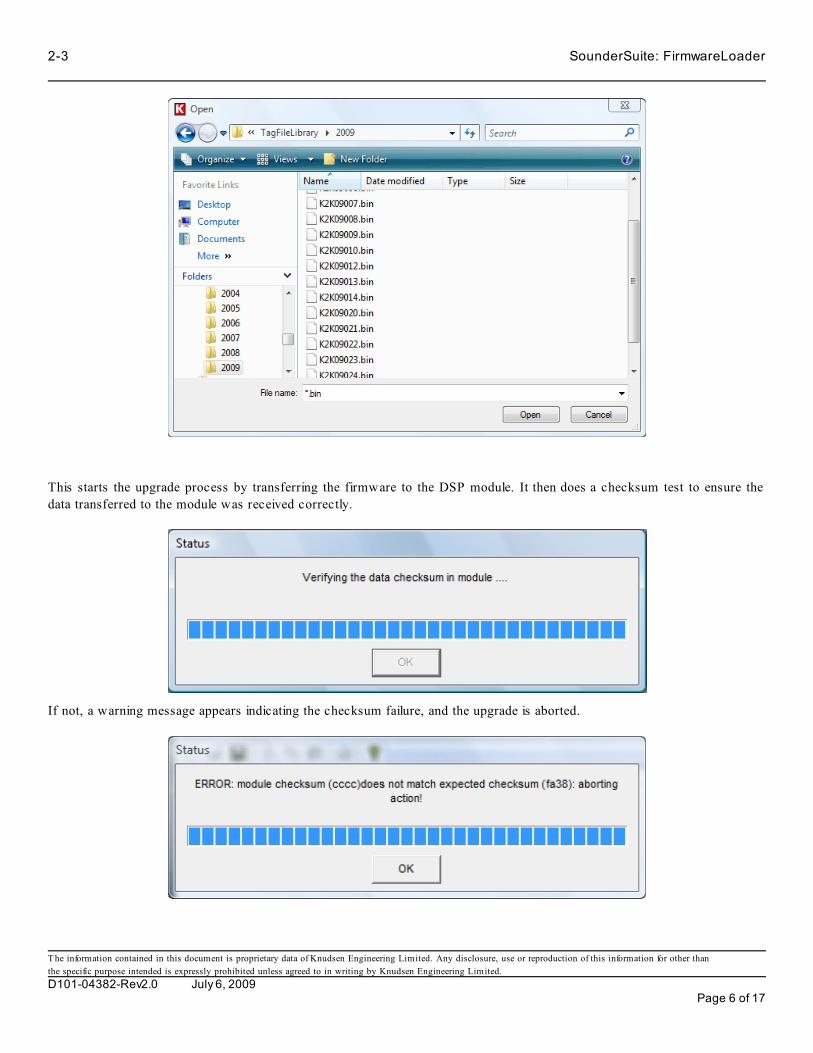
2-3 SounderSuite: FirmwareLoader
T he information contained in this document is proprietary data of Knudsen Engineering Limited. Any disclosure, use or reproduction of this information for other than
the specific purpose intended is expressly prohibited unless agreed to in writing by Knudsen Engineering Limited.
D101-04382-Rev2.0 July 6, 2009Page 6 of 17
This starts the upgrade process by transferring the firmware to the DSP module. It then does a checksum test to ensure the
data transferred to the module was received correctly.
If not, a warning message appears indicating the checksum failure, and the upgrade is aborted.

SounderSuite: FirmwareLoader 2-4
T he information contained in this document is proprietary data of Knudsen Engineering Limited. Any disclosure, use or reproduction of this information for other than
the specific purpose intended is expressly prohibited unless agreed to in writing by Knudsen Engineering Limited.
D101-04382-Rev2.0 July 6, 2009Page 7 of 17
Checksum failures could be a result of USB bus changes that occurred after the Firmware Loader was started, especially if
additional DSP modules were detected. The thing to do in this case is to shutdown Firmware Loader, power off the sounder,
power on the sounder and wait a few seconds to allow Windows to detect the internal modules. Then restart Firmware Loader
and re-attempt the update.
Otherwise, if the checksum tested passed successfully, the application will prompt the user with a confirmation message box.
This is to warn the user that as soon as they accept this action, they will permanently change the code in the module. Normally
this is what is desired, so the user should simply accept the prompt to continue.
The actual programming steps can take a little while, so a progres s bar continues to update the status as the various stages
are run on the embedded module.
During this programming process, at various key points, the application checks for error conditions.
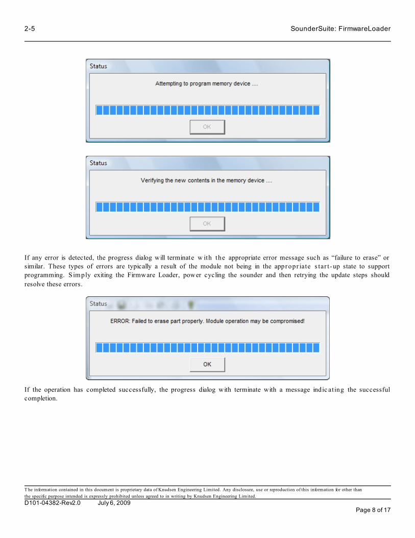
2-5 SounderSuite: FirmwareLoader
T he information contained in this document is proprietary data of Knudsen Engineering Limited. Any disclosure, use or reproduction of this information for other than
the specific purpose intended is expressly prohibited unless agreed to in writing by Knudsen Engineering Limited.
D101-04382-Rev2.0 July 6, 2009Page 8 of 17
If any error is detected, the progress dialog will terminate w ith the appropriate error message such as “failure to erase” or
similar. These types of errors are typically a result of the module not being in the appropr iate s tar t-up state to support
programming. S im ply exiting the Firmware Loader, power cycling the sounder and then retrying the update steps should
resolve these errors.
If the operation has completed successfully, the progress dialog with terminate with a message indic at ing the successful
completion.

SounderSuite: FirmwareLoader 2-6
T he information contained in this document is proprietary data of Knudsen Engineering Limited. Any disclosure, use or reproduction of this information for other than
the specific purpose intended is expressly prohibited unless agreed to in writing by Knudsen Engineering Limited.
D101-04382-Rev2.0 July 6, 2009Page 9 of 17
N.B.: At this time, the new firmware is programmed into the DSP module but it is not actually running yet. The sounder will
need to be power-cycled for the new firmware to become active.
2.3.2 Load CFG Update
The Load CFG Update command is used to start the process for programming new feature configurations into a DSP channel
module. If there are no DSP modules detected, then this menu item will be disabled.
If only one module is detected on the USB bus, the user is taken straight to the dialog to open the desired .ese f ile. If more
than one is detected, then a dialog box with a drop-list is opened to allow the user to select which module should be updated.

2-7 SounderSuite: FirmwareLoader
T he information contained in this document is proprietary data of Knudsen Engineering Limited. Any disclosure, use or reproduction of this information for other than
the specific purpose intended is expressly prohibited unless agreed to in writing by Knudsen Engineering Limited.
D101-04382-Rev2.0 July 6, 2009Page 10 of 17
Once the user has selected and accepted a m odule to update, the File Open dialog appears allowing the user to navigate to
the folder where the necessary configuration file, typically an .ese file, is located.
The user selects the desired configuration file and clicks on Open to load it.
This causes an Update Module ID dialog to appear. Normally the .ese file is specific to a particular DSP module and they are
m atc hed us ing the module’s Serial #. This dialog allows the user to verify he is actually modifying the DSP module that is
really required, and that it enables the features he is expecting for his system. Some features are unit type specific, some are
special order items.

SounderSuite: FirmwareLoader 2-8
T he information contained in this document is proprietary data of Knudsen Engineering Limited. Any disclosure, use or reproduction of this information for other than
the specific purpose intended is expressly prohibited unless agreed to in writing by Knudsen Engineering Limited.
D101-04382-Rev2.0 July 6, 2009Page 11 of 17
If the module identif ication is correct, the user simply clicks the Program Module button to program the setup permanently
into the module. There is no specific feedbac k about the progress; the dialog simply disappears briefly until the task is
complete, then reappears with the info loaded into the module.
The sounder will need to be power-cycled for the changes to become active.

2-9 SounderSuite: FirmwareLoader
T he information contained in this document is proprietary data of Knudsen Engineering Limited. Any disclosure, use or reproduction of this information for other than
the specific purpose intended is expressly prohibited unless agreed to in writing by Knudsen Engineering Limited.
D101-04382-Rev2.0 July 6, 2009Page 12 of 17
2.3.3 Load Printer Firmware
The Load Printer Firmware command is used to start the firmware upgrade of a Printer module. If there are no Printer modules
detected, then this menu item will be disabled.
When the user selects this option, a File Open dialog appears allowing the user to navigate to the folder where the necessary
firmware file, typically a .bin file, is located. The user selects the desired firmware file and clicks on Open to load it.
This starts the upgrade process by transferring the firmware to the DSP module.
It then does a checksum test to ensure the data was transferred to the module correctly.

SounderSuite: FirmwareLoader 2-10
T he information contained in this document is proprietary data of Knudsen Engineering Limited. Any disclosure, use or reproduction of this information for other than
the specific purpose intended is expressly prohibited unless agreed to in writing by Knudsen Engineering Limited.
D101-04382-Rev2.0 July 6, 2009Page 13 of 17
If not, a warning message appears indicating the checksum failure.
Checksum failures could be a result of USB bus changes that occurred after the Firmware Loader was started, especially if
additional DSP modules were detected. The thing to do in this case is shutdown Firmware Loader, power of f the s ounder,
power on the sounder and wait a few seconds to allow Windows to detect the internal modules. Then restart Firmware Loader
and re-attempt the update.
Otherwise, if the checksum tested passed successfully, the application will prompt the user with a confirmation message box.
This is to warn the user that as soon as they accept this action, they will permanently change the code in the module. Normally
this is what is desired, so the user should simply accept the prompt to continue.
The actual programming steps can take a little while so a progress bar continues to update the status as the various stages are
run on the embedded module.
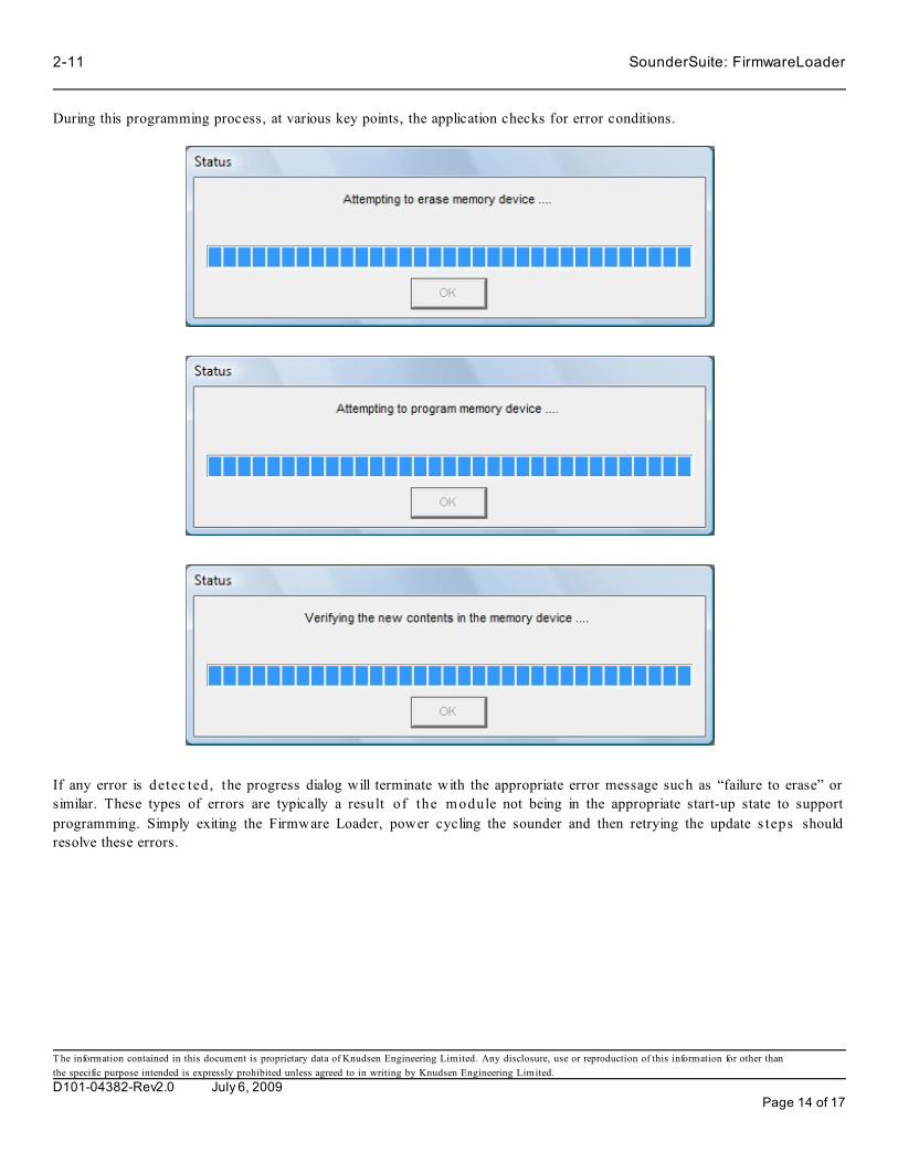
2-11 SounderSuite: FirmwareLoader
T he information contained in this document is proprietary data of Knudsen Engineering Limited. Any disclosure, use or reproduction of this information for other than
the specific purpose intended is expressly prohibited unless agreed to in writing by Knudsen Engineering Limited.
D101-04382-Rev2.0 July 6, 2009Page 14 of 17
During this programming process, at various key points, the application checks for error conditions.
If any error is detec ted, the progress dialog will terminate with the appropriate error message such as “failure to erase” or
similar. These types of errors are typically a result of the m odule not being in the appropriate start-up state to support
programming. Simply exiting the Firmware Loader, power cycling the sounder and then retrying the update s teps should
resolve these errors.

SounderSuite: FirmwareLoader 2-12
T he information contained in this document is proprietary data of Knudsen Engineering Limited. Any disclosure, use or reproduction of this information for other than
the specific purpose intended is expressly prohibited unless agreed to in writing by Knudsen Engineering Limited.
D101-04382-Rev2.0 July 6, 2009Page 15 of 17
If the operation has completed successfully, the progress dialog will terminate with a message indic at ing the successful
completion.
N.B.: At this time, the new firmware is programmed into the DSP module but it is not actually running yet. The sounder will
need to be power-cycled for the new firmware to become active.
2.4 Help
The Help menu provides access to system configuration information that is most useful when contac t ing the factory for
technical assistance. There are no other help features implemented at this time.
2.4.1 Sounder Info
This option pops up the Module Summary dialog box used for summarizing the channel modules detected by the server.

2-13 SounderSuite: FirmwareLoader
T he information contained in this document is proprietary data of Knudsen Engineering Limited. Any disclosure, use or reproduction of this information for other than
the specific purpose intended is expressly prohibited unless agreed to in writing by Knudsen Engineering Limited.
D101-04382-Rev2.0 July 6, 2009Page 16 of 17
The Module Summary dialog provides information regarding the hardware channels detected in the sounder by the Firmware
Loader application. For each hardware module, it reports the programmed serial number , the module’s type, plus the
firmware part number and version. This is a useful reference for verifying the hardware status in the sounder.

SounderSuite: FirmwareLoader 2-14
T he information contained in this document is proprietary data of Knudsen Engineering Limited. Any disclosure, use or reproduction of this information for other than
the specific purpose intended is expressly prohibited unless agreed to in writing by Knudsen Engineering Limited.
D101-04382-Rev2.0 July 6, 2009Page 17 of 17
2.4.2 Tech Support
This option brings up a simple dialog box that provides contact information for technical support. It also provides information
about the type of Windows operating system the Firmware Loader program has detected.
2.4.3 About FirmwareLoader...
The About FirmwareLoader. . . menu item brings up a simple dialog box stating the name of the PC software program, the
KEL part number for the program, and the latest revision number.

SounderSuite -USB
Conversion Utility
Supports Software: D409-04545
D101-04968Revision 1.1
December 22, 2010
Knudsen Engineering Limited10 Industrial Road
Perth, Ontario, Canada

CONTENTS
1 INTRODUCTION. . . . . . . . . . . . . . . . . . . . . . . . . . . . . . . . . . . . . . . . . . . . . . . . . . . . . . . . . . . . . . . . . . . . . . . . . 1-11.1 About this manual. . . . . . . . . . . . . . . . . . . . . . . . . . . . . . . . . . . . . . . . . . . . . . . . . . . . . . . . . . . . . . . . . . . 1-11.2 Software Description. . . . . . . . . . . . . . . . . . . . . . . . . . . . . . . . . . . . . . . . . . . . . . . . . . . . . . . . . . . . . . . . . 1-11.3 Technical Support. . . . . . . . . . . . . . . . . . . . . . . . . . . . . . . . . . . . . . . . . . . . . . . . . . . . . . . . . . . . . . . . . . . 1-1
2 OPERATING INSTRUCTIONS. . . . . . . . . . . . . . . . . . . . . . . . . . . . . . . . . . . . . . . . . . . . . . . . . . . . . . . . . . . . . . 2-12.1 Description.. . . . . . . . . . . . . . . . . . . . . . . . . . . . . . . . . . . . . . . . . . . . . . . . . . . . . . . . . . . . . . . . . . . . . . . . 2-12.2 Select Source File. . . . . . . . . . . . . . . . . . . . . . . . . . . . . . . . . . . . . . . . . . . . . . . . . . . . . . . . . . . . . . . . . . . 2-1
The information contained in this document is proprietary data of Knudsen Engineering Limited. Any disclosure, use or reproduction of this information for other thanthe specific purpose intended is expressly prohibited unless agreed to in writing by Knudsen Engineering Limited.
D101-04968-Rev1.1 December 22, 2010 Page 2 of 5

SounderSuite: Conversion Utility 1-1
1 INTRODUCTION
1.1 About this manual
This manual provides information about the Conversion Utility application, D409-04545, ComversionUtility.exe. Thisprogram has been designed to give the user the ability to convert between supported data file types.
1.2 Software Description
The echosounder control software is capable recording various data formats in real time. Sometimes, a user may decide notto record a particular format type during his real-time survey operation and then realize after the fact he needs that particulardata type for his post-processing or his client’s deliverables. The Conversion Utility provides the user the ability to createa file of the given type from a file of another type that was recorded in real-time. The conversion process is not the idealmethod for generating some format types since the source file used may be lacking some information that would have beenavailable during real-time recording but the Conversion Utility will populate as many fields as technically possible with whatdata is available.
The Conversion Utility also allows the user to convert older formats of KEB binary files for readback in the PostSurveyapplication.
1.3 Technical Support
For technical support or to report problems please contact your local representative or:
Technical SupportKnudsen Engineering Limited 10 Industrial RoadPerth, OntarioK7H 3P2
Voice: (613) 267-1165 8:30 am to 5:00 pm E.S.T. Core HoursFax: (613) 267-7085E-Mail: [email protected]: http://knudsenengineering.com/
The information contained in this document is proprietary data of Knudsen Engineering Limited. Any disclosure, use or reproduction of this information for other thanthe specific purpose intended is expressly prohibited unless agreed to in writing by Knudsen Engineering Limited.
D101-04968-Rev1.1 December 22, 2010 Page 3 of 5

2-1 SounderSuite: Conversion Utility
2 OPERATING INSTRUCTIONS
2.1 Description
Then Conversion Utility application is a very basic application intended for simply converting one data file type to anotherdata file type. When the user runs the application, a simple dialog box appears with the key controls needed to select sourcefiles, destination folder, and output file format.
2.2 Select Source File
The first item in the dialog is the selection entry for the file or files to be converted. The user can type in a file path and nameexplicitly, or click on the button at the right of the text entry to pull up a File Open dialog. In this dialog, the user can filterwhat type of files to view:
• Supported File Types (*.keb, *.sgy)• SEG-Y Files (*.sgy)• Knudsen Binary Files (*.keb)• All Files (*.*)
The dialog supports the selection of multiple files; the application can handle up to 200 files in one batch session. Multipleinput file formats can be supported; the application will run a detection algorithm on each file prior to starting the conversionon that particular input file.
• Select Destination
The next item in the dialog is the destination location. The user can simply type in a path and file name root or click the buttonon the right of the text entry to pull up a Save As dialog. By default, the filename is preloaded with <UseNameRoot>. Thisis required for doing batch jobs to make the application use the source file’s name to construct the name for the new convertedfile. For single file conversions, the user can enter any name root they prefer.
The information contained in this document is proprietary data of Knudsen Engineering Limited. Any disclosure, use or reproduction of this information for other thanthe specific purpose intended is expressly prohibited unless agreed to in writing by Knudsen Engineering Limited.
D101-04968-Rev1.1 December 22, 2010 Page 4 of 5
SounderSuite: Conversion Utility 2-2
• Select Format
The final item that needs to be set before the conversion operation can be run is to select the file type to be created by theconversion action. The available options for file types are:
SEG-Y - Rev0 (See D101-03021: KEL SEGY Format Usage Definition for details)
SEG-Y - KEL Extended
XTF (See D101-03322: KEL XTF Format Usage Definition for details)
KEA
KEB - Compressed (See D101-04842: File Format Specification KEB - D3 Format for details)
KEB - Uncompressed
Only one output data type can be selected. If more than one type is desired, the conversion process needs to be run for eachtype to be converted.
If a SEG-Y format option is selected, an additional checkbox control is supplied to the user. This control allows the user toselect if they would like to ignore any differences between fields in the main file header and the individual trace headers orif they want the application to open a new file each time a difference is detected.
The information contained in this document is proprietary data of Knudsen Engineering Limited. Any disclosure, use or reproduction of this information for other thanthe specific purpose intended is expressly prohibited unless agreed to in writing by Knudsen Engineering Limited.
D101-04968-Rev1.1 December 22, 2010 Page 5 of 5

File Format Specification
KEB - D3 Format
D101-04842Revision 1.2July 6, 2009
Knudsen Engineering Limited10 Industrial Road
Perth, Ontario, Canada

T he information contained in this document is proprietary data of Knudsen Engineering Limited. Any disclosure, use or reproduction of this information for other than
the specific purpose intended is expressly prohibited unless agreed to in writing by Knudsen Engineering Limited.
D101-04842-Rev1.2 July 6, 2009 2 of 8
CONTENTS
1 File Specification. . . . . . . . . . . . . . . . . . . . . . . . . . . . . . . . . . . . . . . . . . . . . . . . . . . . . . . . . . . . . . . . . . . . . 1-3
1.1 Overview. . . . . . . . . . . . . . . . . . . . . . . . . . . . . . . . . . . . . . . . . . . . . . . . . . . . . . . . . . . . . . . . . . . . 1-3
1.2 File Type Id Preamble. . . . . . . . . . . . . . . . . . . . . . . . . . . . . . . . . . . . . . . . . . . . . . . . . . . . . . . . . . . 1-3
1.3 Record Preamble. . . . . . . . . . . . . . . . . . . . . . . . . . . . . . . . . . . . . . . . . . . . . . . . . . . . . . . . . . . . . . . 1-4
1.4 Ping Record: Record Type D3: Variable Length Multiple Channel Envelope. . . . . . . . . . . . . . . . . . . . . . . 1-4
1.5 Event Mark Code Definitions. . . . . . . . . . . . . . . . . . . . . . . . . . . . . . . . . . . . . . . . . . . . . . . . . . . . . . . 1-8
LIST OF TABLES
Table 1.1: Record Preamble. . . . . . . . . . . . . . . . . . . . . . . . . . . . . . . . . . . . . . . . . . . . . . . . . . . . . . . . . . . . . . . . . . . 1-4
Table 1.2: Ping Record - Uncompressed. . . . . . . . . . . . . . . . . . . . . . . . . . . . . . . . . . . . . . . . . . . . . . . . . . . . . . . . . . . 1-4
Table 1.3: Event Mark Codes. . . . . . . . . . . . . . . . . . . . . . . . . . . . . . . . . . . . . . . . . . . . . . . . . . . . . . . . . . . . . . . . . . 1-8

T he information contained in this document is proprietary data of Knudsen Engineering Limited. Any disclosure, use or reproduction of this information for other than
the specific purpose intended is expressly prohibited unless agreed to in writing by Knudsen Engineering Limited.
D101-04842-Rev1.2 July 6, 2009 3 of 8
1 File Specification
1.1 Overview
The envelope data for each channel can be recorded in a binary data f ile for use by post-processing software. Every ping
cycle, one record is stored with header information and raw data for each frequency channel. Each record is variable in length
with a current maximum possible number of 6772 bytes, and can be compressed using a Huffman compression algor ithm.
The storage device for these files should have sufficient disk space free to store the vast amounts of data generated, especially
when working in shallow water where the faster ping rate results in a larger volume of data being generated.
The binary data files are recorded using the following basic structural format:
File Type Id Preamble (40 bytes)
Record Preamble 1 (10 bytes)
Ping Record 1 (variable number of bytes, compressed if Huffman)
Record Preamble21 (10 bytes)
Ping Record 2 (variable number of bytes, compressed if Huffman)
Record Preamble31 (10 bytes)
Ping Record 3 (variable number of bytes, compressed if Huffman)
.
.
.
Record Preamble N (10 bytes)
Ping Record N (variable number of bytes, compressed if Huffman)
The recording program will write data records to one file for up to 20000 pings, then the current file will be closed and a new
one will be opened for subsequent data recording.
1.2 File Type Id Preamble
The first 40 bytes of the file are used for a file type identification preamble for the playback software to use. This is used to
determine if the file is in the valid format supported by the version of software being used.
Example:
KEB D409-04184 V1.00 Huffman
(pad unused character locations with spaces)
where, KEB identifies the file as a KEL Binary file,
D409-04184 identifies the part number of the program used to record/convert the data,
V1.00 identifies the version of the program used to record/convert the data.
Huffman indicates that the data is in a compressed format (not present for uncompressed files)
After the File Type Id Preamble, the actual data records are stored as they are received. As soon as a record is received, it is
recorded to the disk file. Records are recorded to the file in the same order as they were received (time stamps must be in
sequential order). Multiple types of records can be stored in the binary file; ie Envelope data records, serial port sensor data
records, configuration records, etc (only Envelope records are actually implemented at this time). The original data record
form at is shown in Table 1.2. The data can be stored in this format, or the user can enable data compression. When
c om pres s ion is enabled, each data record as shown in Table 1.2 has a Huffman compression algorithm applied to it. T he
result of the compression is stored in the file. The playback application runs the matching decompression algorithm to access
the data records.

T he information contained in this document is proprietary data of Knudsen Engineering Limited. Any disclosure, use or reproduction of this information for other than
the specific purpose intended is expressly prohibited unless agreed to in writing by Knudsen Engineering Limited.
D101-04842-Rev1.2 July 6, 2009 4 of 8
1.3 Record Preamble
Each data record is preceded by a Record Preamble that provides quick access, particularly for compressed records, to useful
info about the record. This data is us ed by the PostSurvey application for faster analysis of the data statistics. See the
following description about the Data Records for some of the field definitions.
Table 1.1: Record Preamble
FIELD DESCRIPTION DATA
TYPE
BYTE
COUNT
Record Type Code BYTE 1
File offset to start of record after the record
preamble
long 4
Record Size expressed in bytes long 4
Event mark code BYTE 1
Byte Total 10
1.4 Ping Record: Record Type D3: Variable Length Multiple Channel Envelope
Table 1.2: Ping Record - Uncompressed
FIELD DESCRIPTION DATA FORMAT / RANGE Data Type BYTE
COUNT
BYTE
OFFSET
Record Identification Information
Record Id D3h WORD 2 0000h
Record Length data dependent WORD 2 0002h
Record Number 0 to 65536 WORD 2 0004h
# of Channel Records 1 to 8 WORD 2 0006h
Reserved Bytes NULL WORD 20 0008h
Byte Count: Section Total 28
Record TimeStamp
Day 1 to 31 WORD 2 001Ch
Month 1 to 12 WORD 2 001Eh
Year yyyy WORD 2 0020h
Hour 0 to 23 WORD 2 0022h
Minute 0 to 59 WORD 2 0024h
Seconds 0 to 59 WORD 2 0026h
Milliseconds 0 to 999 WORD 2 0028h
Julian Day 1 to 365 WORD 2 002Ah
TimeTagSeconds Seconds since midnight Jan 1, 1970 DWORD 4 002Ch
TimeTagMilliseconds Millisecond portion of timetag DWORD 4 0030h
FrameCountAtPingStart DWORD 4 0034h
FrameCountAtStorage DWORD 4 0038h

FIELD DESCRIPTION DATA FORMAT / RANGE Data Type BYTE
COUNT
BYTE
OFFSET
T he information contained in this document is proprietary data of Knudsen Engineering Limited. Any disclosure, use or reproduction of this information for other than
the specific purpose intended is expressly prohibited unless agreed to in writing by Knudsen Engineering Limited.
D101-04842-Rev1.2 July 6, 2009 5 of 8
Reserved Bytes NULL WORD 12 003Ch
Byte Count: Section Total 44
Sounder Parameters Shared for Each Channel
Working Units Code 0 = metres
1 = feet
2 = fathoms
WORD 2 0048h
Speed of sound 1300 to 1700 m/s
4265 to 5577 ft/s
710 to 929 fm/s
WORD 2 004Ah
Pinger Mode
(3200 series only)
0 = off,
1 = 1/8th second sweep
2 = 1/4th second sweep
3 = 1/2th second sweep
4 = 1 second sweep
5 = 2 second sweep
6 = 4 second sweep
WORD 2 004Ch
Mux Enable
(sweep systems only)
0 = off
1 = HF
2 = LF
3 = Both
WORD 2 004Eh
Mux Transducer Number
(sweep systems only)
0 ( no multiplexer)
1 to 8
WORD 2 0050h
Reserved Bytes NULL WORD 20 0056h
Byte Count: Section Total 30
Sensor Data Parameters Shared for Each Channel
Heave (expressed in m, feet, or
fathoms)
data dependent float 4 0066h
Roll Angle [degrees] data dependent float 4 006Ah
Pitch Angle [degrees] data dependent float 4 006Eh
Heading Angle [degrees] data dependent float 4 0072h
HeaveTimeTagSeconds Seconds since midnight Jan 1, 1970 DWORD 4 0076h
HeaveTimeTagMilliseconds Millisecond portion of timetag DWORD 4 007Ah
Heave Sensor Quality 0 = invalid
1 = okay
WORD 2 007Eh
Position Format - Lat/Long or
X/Y
0 = undefined format
1 = Latitude/Longitude
2 = X/Y (from Hypack)
WORD 2 0080h
Latitude (expressed in degrees)
or
Y (from Hypack or GPS)
data dependent double 8 0082h

FIELD DESCRIPTION DATA FORMAT / RANGE Data Type BYTE
COUNT
BYTE
OFFSET
T he information contained in this document is proprietary data of Knudsen Engineering Limited. Any disclosure, use or reproduction of this information for other than
the specific purpose intended is expressly prohibited unless agreed to in writing by Knudsen Engineering Limited.
D101-04842-Rev1.2 July 6, 2009 6 of 8
Longitude (expressed in
degrees)
or
X (from Hypack or GPS)
data dependent double 8 008Ah
PosTimeTagSeconds Seconds since midnight Jan 1, 1970 DWORD 4 0092h
PosTimeTagMillieconds Millisecond portion of timetag DWORD 4 0096h
Boat Speed (from Hypack or
GPS)
tbd float 4 009Ah
Boat Heading (from Hypack or
GPS)
tbd float 4 009Eh
VTGTimeTagSeconds Seconds since midnight Jan 1, 1970 DWORD 4 00A2h
VTGTimeTagMillieconds Millisecond portion of timetag DWORD 4 00A6h
Towfish / AUV Depth to be determined float 4 00AAh
Reserved Bytes NULL WORD 36 00AEh
Byte Count: Section Total 108
Channel Parameters
Module Serial Number yynnnn
K2K-yy-nnnn
LONG 4 00D2h
Module Channel Reference 1 to 4 WORD 2 00D6h
Nominal Frequency 3500 to 210000 Hz float 4 00D8h
Channel Usage Code 0 = undefined
1 = bathymetry
2 = sidescan port
3 = sidescan starboard
WORD 2 00DCh
Signal Type Code 0 = CW
1 = Chirp
WORD 2 00DEh
Start Frequency [Hz] float 4 00E0h
Stop Frequency [Hz] float 4 00E4h
Bandwidth [Hz] float 4 00E8h
Sample Rate [Hz] float 4 00ECh
Envelope Detection Code 0 = square law detection
1= amplitude detection
WORD 2 00F0h
Transmit power level code 1 to 4 WORD 2 00F2h
Pulse length [ms] 0.0625ms to 4ms (1600 series)
0.0625ms to 24ms (3200 series)
float 4 00F4h
Gain Mode 0 = manual
1 = Auto (AGC)
WORD 2 00F8h
Gain Value [dB] 0 to 96 float 4 00FAh
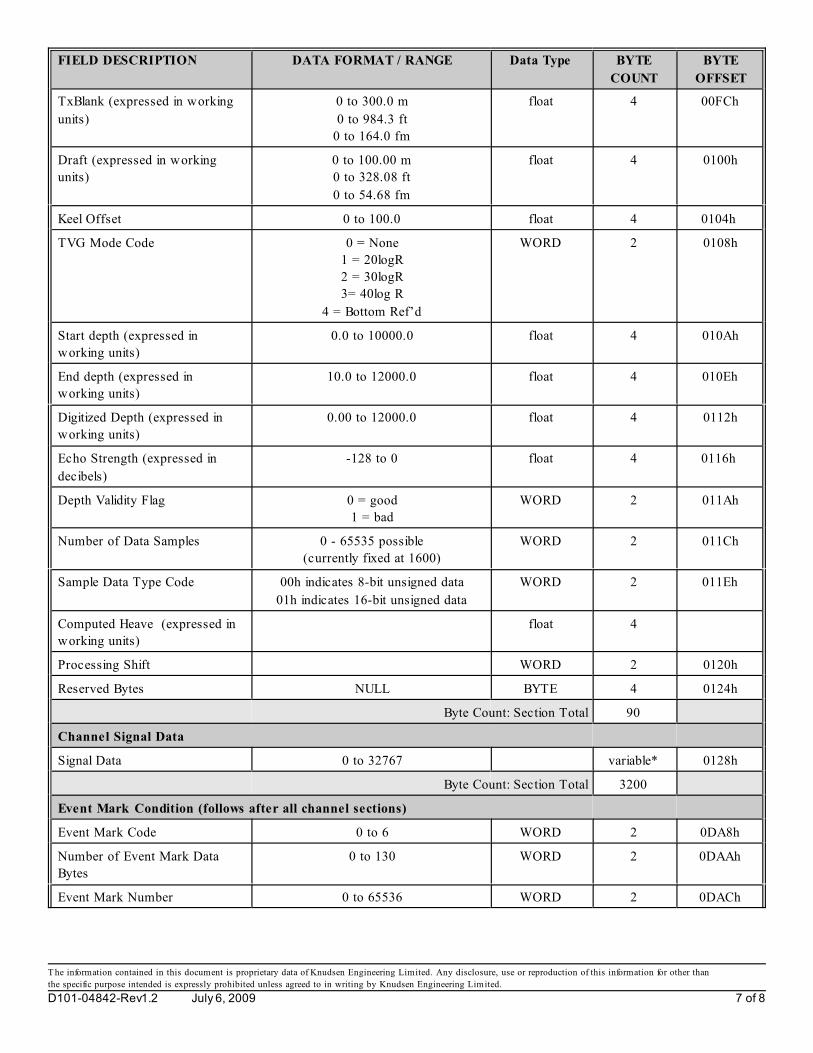
FIELD DESCRIPTION DATA FORMAT / RANGE Data Type BYTE
COUNT
BYTE
OFFSET
T he information contained in this document is proprietary data of Knudsen Engineering Limited. Any disclosure, use or reproduction of this information for other than
the specific purpose intended is expressly prohibited unless agreed to in writing by Knudsen Engineering Limited.
D101-04842-Rev1.2 July 6, 2009 7 of 8
TxBlank (expressed in working
units)
0 to 300.0 m
0 to 984.3 ft
0 to 164.0 fm
float 4 00FCh
Draft (expressed in working
units)
0 to 100.00 m
0 to 328.08 ft
0 to 54.68 fm
float 4 0100h
Keel Offset 0 to 100.0 float 4 0104h
TVG Mode Code 0 = None
1 = 20logR
2 = 30logR
3= 40log R
4 = Bottom Ref’d
WORD 2 0108h
Start depth (expressed in
working units)
0.0 to 10000.0 float 4 010Ah
End depth (expressed in
working units)
10.0 to 12000.0 float 4 010Eh
Digitized Depth (expressed in
working units)
0.00 to 12000.0 float 4 0112h
Echo Strength (expressed in
decibels)
-128 to 0 float 4 0116h
Depth Validity Flag 0 = good
1 = bad
WORD 2 011Ah
Number of Data Samples 0 - 65535 possible
(currently fixed at 1600)
WORD 2 011Ch
Sample Data Type Code 00h indicates 8-bit unsigned data
01h indicates 16-bit unsigned data
WORD 2 011Eh
Computed Heave (expressed in
working units)
float 4
Processing Shift WORD 2 0120h
Reserved Bytes NULL BYTE 4 0124h
Byte Count: Section Total 90
Channel Signal Data
Signal Data 0 to 32767 variable* 0128h
Byte Count: Section Total 3200
Event Mark Condition (follows after all channel sections)
Event Mark Code 0 to 6 WORD 2 0DA8h
Number of Event Mark Data
Bytes
0 to 130 WORD 2 0DAAh
Event Mark Number 0 to 65536 WORD 2 0DACh

FIELD DESCRIPTION DATA FORMAT / RANGE Data Type BYTE
COUNT
BYTE
OFFSET
T he information contained in this document is proprietary data of Knudsen Engineering Limited. Any disclosure, use or reproduction of this information for other than
the specific purpose intended is expressly prohibited unless agreed to in writing by Knudsen Engineering Limited.
D101-04842-Rev1.2 July 6, 2009 8 of 8
Event Mark Annotation String data dependent char variable
(max =
145)
0DAEh
Byte Count: Section Total 151
Byte Count Structure Total (1 channel) 3651 0E3Fh
Byte Count Structure Total (4 channels) 13521 34C1h
* Although the channel data definition allow s for variable number of data samples, currently the number is fixed to 1600
words (3200 bytes) which is the value used to determine byte count totals and data offsets.
1.5 Event Mark Code Definitions
Event marks can be init iated from a number of sources; the Event Mark code indicates the source of the event mark as
described in T able 1 .3 . Serial Port and Hypack initiated event marks often have variable-length annotation strings recorded
as well.
Table 1.3: Event Mark Codes
Code # Code Source
0 No Fix
1 Timebase
2 Client Application
3 Hyapck
4 Remote
5 Serial

KEL SEGY FORMAT USAGE DEFINITION 1 of 11
D101-03021-Rev2.2
SEG-Y Structure definitions designed from documentation supplied by Scripps Institution of Oceanography.Note: Data is recorded in Big-Endian format (most significant byte first) to match original definition.
REEL IDENTIFICATION HEADER (Main Header)
SEG-Y Rev 0 (1979) SEG-Y Rev1 (2002) KEL Usage
Byte #s Specification Description Byte #s Specification Description Format Label Usage Description
0000-3199 3200 Byte EBCDIC Reel header 0000-3199 3200 Byte EBCDIC Reel header char text[40][80] EBCDIC format header using ASCII-to-EDCBICconversion code credited to T. O’Brien of USGS.
3200-3203 Job identification number 3200-3203 Job identification number DWORD Job_id unused
3204-3207 Line number (one per reel) 3204-3207 Line number (one per reel) DWORD line_number The survey line number assigned with the Record, StartLine dialog in the Echo Control application, and whichforms part of the file name. See Note 1.
3208-3211 Reel Number 3208-3211 Reel Number DWORD reel_number File number in survey line. Note 2
3212-3213 Number of data traces/record 3212-3213 Number of data traces/record WORD data_trace_number set = 1
3214-3215 Number of aux traces/record 3214-3215 Number of aux traces/record WORD aux_trace_number set = 0
3216-3217 Sample interval in microsecs (for this reel ofdata)
3216-3217 Sample interval in microsecs (for this reel ofdata)
WORD reel_sample_time 1000000 / Data Rate Note 3
3218-3219 Sample interval in microsecs (for originalfield recording)
3218-3219 Sample interval in microsecs (for originalfield recording)
WORD orig_sample_time unused
3220-3221 Number of samples per data trace (for thisreel of data)
3220-3221 Number of samples per data trace (for thisreel of data)
WORD reel_sample_number number of data samples
3222-3223 Number of samples per data trace (fororiginal field recording)
3222-3223 Number of samples per data trace (fororiginal field recording)
WORD orig_sample_number unused
3224-3225 Data sample format code:
1 floating point (4 bytes)2 fixed point (4 bytes)3 fixed point (2 bytes)4 fixed point with gain code (4 bytes)
Auxilary traces use the same number ofbytes per sample.
3224-3225 Data sample format code:
1 floating point (4 bytes)2 fixed point (4 bytes)3 fixed point (2 bytes)4 fixed point with gain code (4 bytes)
Auxilary traces use the same number ofbytes per sample.
WORD sample_format Set = 3 fixed point (2 bytes) Note 4
3226-3227 CDP fold (Expected number of data tracesper CDP ensemble)
3226-3227 CDP fold (Expected number of data tracesper CDP ensemble)
WORD cdp_fold set = 1

KEL SEGY FORMAT USAGE DEFINITION 2 of 11
SEG-Y Rev 0 (1979) SEG-Y Rev1 (2002) KEL Usage
Byte #s Specification Description Byte #s Specification Description Format Label Usage Description
D101-03021-Rev2.2
3228-3229 Trace sorting code:
1 as recorded (no sort)2 CDP ensemble3 single fold continuous profile4 horizontally stacked
3228-3229 Trace sorting code:
1 as recorded (no sort)2 CDP ensemble3 single fold continuous profile4 horizontally stacked
WORD trace_sort set = 1 as recorded
3230-3231 Vertical sum code:
1 no sum2 two sumN N sum (N=32767)
3230-3231 Vertical sum code:
1 no sum2 two sumN N sum (N=32767)
WORD vertical_sum unused
3232-3233 Sweep frequency at start 3232-3233 Sweep frequency at start WORD sweep_freq_start unused
3234-3235 Sweep frequency at end 3234-3235 Sweep frequency at end WORD sweep_freq_end unused
3236-3237 Sweep length(ms) 3236-3237 Sweep length(ms) WORD sweep_time unused
3238-3239 Sweep type code:
1 linear2 parabolic3 exponential4 other
3238-3239 Sweep type code:
1 linear2 parabolic3 exponential4 other
WORD sweep_type unused
3240-3241 Trace number of sweep channel 3240-3241 Trace number of sweep channel WORD sweep_trace_number unused
3242-3243 Sweep trace taper length in ms at start(the taper starts at zero time and is effectivefor this length)
3242-3243 Sweep trace taper length in ms at start(the taper starts at zero time and is effectivefor this length)
WORD sweep_taper_time_start unused
3244-3245 Sweep trace tape length in ms at end(the ending taper starts at sweep lengthminus the taper length at end)
3244-3245 Sweep trace tape length in ms at end(the ending taper starts at sweep lengthminus the taper length at end)
WORD sweep_taper_time_end unused
3246-3247 Taper type:
1 linear2 cos*cos3 other
3246-3247 Taper type:
1 linear2 cos*cos3 other
WORD taper_type unused
3248-3249 Correlated data traces:
1 no2 yes
3248-3249 Correlated data traces:
1 no2 yes
WORD correlate_trace unused
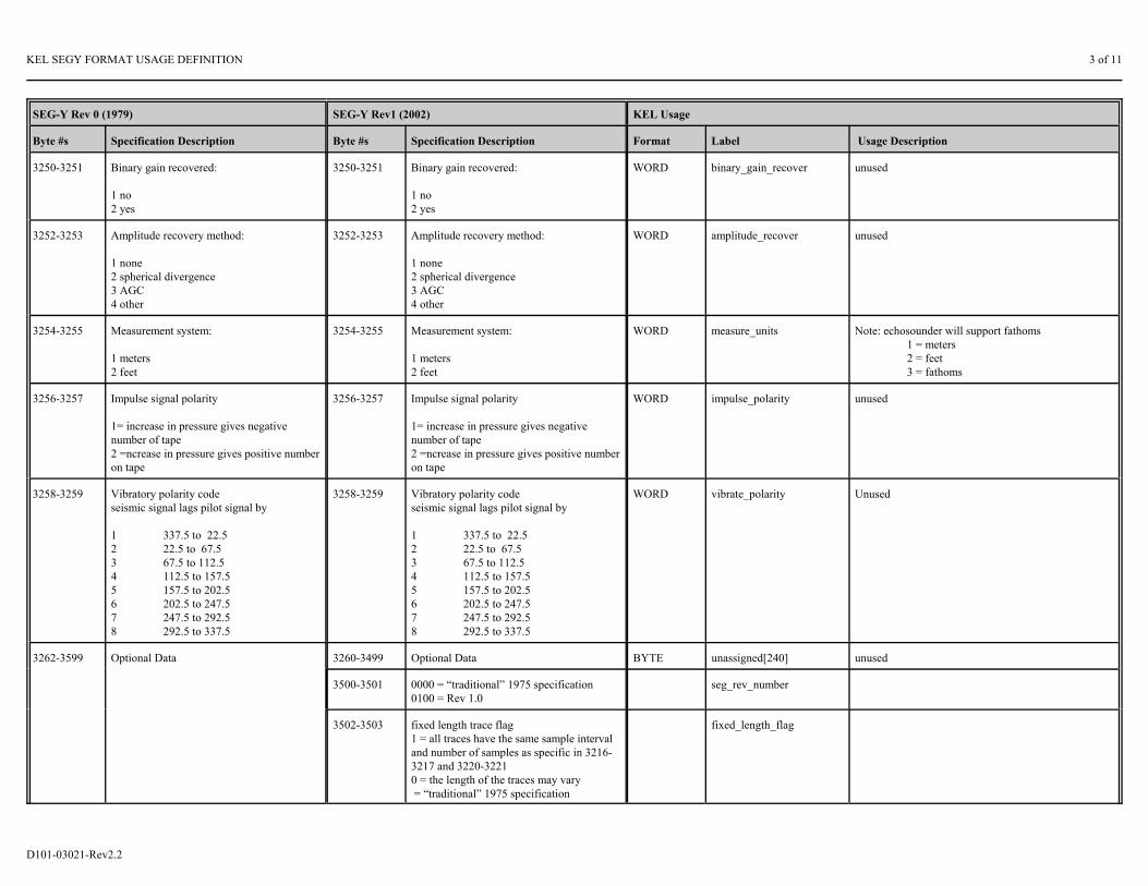
KEL SEGY FORMAT USAGE DEFINITION 3 of 11
SEG-Y Rev 0 (1979) SEG-Y Rev1 (2002) KEL Usage
Byte #s Specification Description Byte #s Specification Description Format Label Usage Description
D101-03021-Rev2.2
3250-3251 Binary gain recovered:
1 no2 yes
3250-3251 Binary gain recovered:
1 no2 yes
WORD binary_gain_recover unused
3252-3253 Amplitude recovery method:
1 none2 spherical divergence3 AGC4 other
3252-3253 Amplitude recovery method:
1 none2 spherical divergence3 AGC4 other
WORD amplitude_recover unused
3254-3255 Measurement system:
1 meters2 feet
3254-3255 Measurement system:
1 meters2 feet
WORD measure_units Note: echosounder will support fathoms1 = meters2 = feet3 = fathoms
3256-3257 Impulse signal polarity
1= increase in pressure gives negativenumber of tape2 =ncrease in pressure gives positive numberon tape
3256-3257 Impulse signal polarity
1= increase in pressure gives negativenumber of tape2 =ncrease in pressure gives positive numberon tape
WORD impulse_polarity unused
3258-3259 Vibratory polarity codeseismic signal lags pilot signal by
1 337.5 to 22.52 22.5 to 67.53 67.5 to 112.54 112.5 to 157.55 157.5 to 202.56 202.5 to 247.57 247.5 to 292.58 292.5 to 337.5
3258-3259 Vibratory polarity codeseismic signal lags pilot signal by
1 337.5 to 22.52 22.5 to 67.53 67.5 to 112.54 112.5 to 157.55 157.5 to 202.56 202.5 to 247.57 247.5 to 292.58 292.5 to 337.5
WORD vibrate_polarity Unused
3262-3599 Optional Data 3260-3499 Optional Data BYTE unassigned[240] unused
3500-3501 0000 = “traditional” 1975 specification0100 = Rev 1.0
seg_rev_number
3502-3503 fixed length trace flag1 = all traces have the same sample intervaland number of samples as specific in 3216-3217 and 3220-32210 = the length of the traces may vary = “traditional” 1975 specification
fixed_length_flag
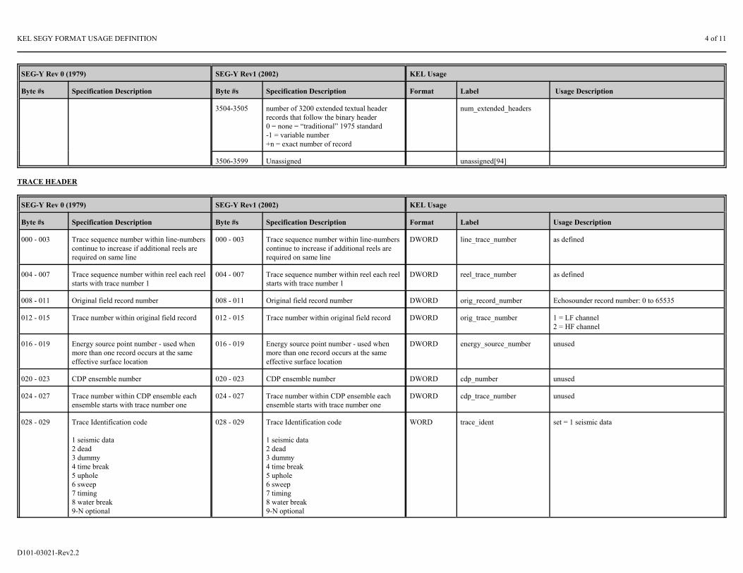
KEL SEGY FORMAT USAGE DEFINITION 4 of 11
SEG-Y Rev 0 (1979) SEG-Y Rev1 (2002) KEL Usage
Byte #s Specification Description Byte #s Specification Description Format Label Usage Description
D101-03021-Rev2.2
3504-3505 number of 3200 extended textual headerrecords that follow the binary header0 = none = “traditional” 1975 standard-1 = variable number+n = exact number of record
num_extended_headers
3506-3599 Unassigned unassigned[94]
TRACE HEADER
SEG-Y Rev 0 (1979) SEG-Y Rev1 (2002) KEL Usage
Byte #s Specification Description Byte #s Specification Description Format Label Usage Description
000 - 003 Trace sequence number within line-numberscontinue to increase if additional reels arerequired on same line
000 - 003 Trace sequence number within line-numberscontinue to increase if additional reels arerequired on same line
DWORD line_trace_number as defined
004 - 007 Trace sequence number within reel each reelstarts with trace number 1
004 - 007 Trace sequence number within reel each reelstarts with trace number 1
DWORD reel_trace_number as defined
008 - 011 Original field record number 008 - 011 Original field record number DWORD orig_record_number Echosounder record number: 0 to 65535
012 - 015 Trace number within original field record 012 - 015 Trace number within original field record DWORD orig_trace_number 1 = LF channel2 = HF channel
016 - 019 Energy source point number - used whenmore than one record occurs at the sameeffective surface location
016 - 019 Energy source point number - used whenmore than one record occurs at the sameeffective surface location
DWORD energy_source_number unused
020 - 023 CDP ensemble number 020 - 023 CDP ensemble number DWORD cdp_number unused
024 - 027 Trace number within CDP ensemble eachensemble starts with trace number one
024 - 027 Trace number within CDP ensemble eachensemble starts with trace number one
DWORD cdp_trace_number unused
028 - 029 Trace Identification code
1 seismic data2 dead3 dummy4 time break5 uphole6 sweep7 timing8 water break9-N optional
028 - 029 Trace Identification code
1 seismic data2 dead3 dummy4 time break5 uphole6 sweep7 timing8 water break9-N optional
WORD trace_ident set = 1 seismic data

KEL SEGY FORMAT USAGE DEFINITION 5 of 11
SEG-Y Rev 0 (1979) SEG-Y Rev1 (2002) KEL Usage
Byte #s Specification Description Byte #s Specification Description Format Label Usage Description
D101-03021-Rev2.2
030 - 031 Number of vertically summed tracesyeilding this trace (1 = one trace, 2 = two,etc)
030 - 031 Number of vertically summed tracesyeilding this trace (1 = one trace, 2 = two,etc)
WORD vertical_sum set = 1
032 - 033 Number of horizontally stacked tracesyeilding this trace (1 = one trace, 2 = two,etc)
032 - 033 Number of horizontally stacked tracesyeilding this trace (1 = one trace, 2 = two,etc)
WORD horizontal_sum set = 1
034 - 035 Data use:
1=production 2=test
034 - 035 Data use:
1=production 2=test
WORD data_use unused
036 - 039 Distance from source point to receiver group(negative if opposite to direction in whichline is shot)
036 - 039 Distance from source point to receiver group(negative if opposite to direction in whichline is shot)
DWORD source_receiver_dist unused
040 - 043 Receiver group elevation; all elevations areabove sea-level are positive and below arenegative
040 - 043 Receiver group elevation; all elevations areabove sea-level are positive and below arenegative
DWORD receiver_elevation unused
044 - 047 Surface elevation at source 044 - 047 Surface elevation at source DWORD surface_elevation unused
048 - 051 Source depth below surface (positivenumber)
048 - 051 Source depth below surface (positivenumber)
DWORD source_depth set = echosounder draft parameter
052 - 055 Datum elevation at receiver group 052 - 055 Datum elevation at receiver group DWORD datum_receiver_elevation unused
056 - 059 Datum elevation at source 056 - 059 Datum elevation at source DWORD datum_source_elevation unused
060 - 063 Water depth at source 060 - 063 Water depth at source DWORD water_depth_source digitized depth, as determined by the echosounder
064 - 067 Water depth at group 064 - 067 Water depth at group DWORD water_depth_group unused
068 - 069 Scaler to be applied to all elevations anddepths in items 40-67 (hex) to give realvalues.
Scaler = 1,+/- 10, +/- 100,+/- 1000, +/-10000.
If positive scaler used as multiplier, ifnegative scaler used as divisor.
068 - 069 Scaler to be applied to all elevations anddepths in items 40-67 (hex) to give realvalues.
Scaler = 1,+/- 10, +/- 100,+/- 1000, +/-10000.
If positive scaler used as multiplier, ifnegative scaler used as divisor.
WORD scaler_1 set = -100
070 - 071 Scaler to be applied to all coordinates in 72 -87 (hex) to give the real values.
(same as above)
070 - 071 Scaler to be applied to all coordinates in 72 -87 (hex) to give the real values.
(same as above)
WORD scaler_2 set = -1000

KEL SEGY FORMAT USAGE DEFINITION 6 of 11
SEG-Y Rev 0 (1979) SEG-Y Rev1 (2002) KEL Usage
Byte #s Specification Description Byte #s Specification Description Format Label Usage Description
D101-03021-Rev2.2
072 - 075 Source coordinate - X 072 - 075 Source coordinate - X DWORD source_coord_x longitude[expressed in degrees] * 60 * 60 Note 5
076 - 079 Source coordinate - Y 076 - 079 Source coordinate - Y DWORD source_coord_y latitude[expressed in degrees] * 60 * 60
080 - 083 Group coordinate - X 080 - 083 Group coordinate - X DWORD group_coord_x unused
084 - 087 Group coordinate - Y 084 - 087 Group coordinate - Y DWORD group_coord_y unused
088 - 089 Coordinate units:
1 = length (meters or feet)2 = seconds of arc
088 - 089 Coordinate units:
1 = length (meters or feet)2 = seconds of arc
WORD coord_units set = 2 (seconds of arc)
090 - 091 Weathering velocity 090 - 091 Weathering velocity WORD weathering_velocity unused
092 - 093 Subweathering velocity 092 - 093 Subweathering velocity WORD subweathering_velocity unused
094 - 095 Uphole time at source 094 - 095 Uphole time at source WORD source_uphole_time unused
096 - 097 Uphole time at group 096 - 097 Uphole time at group WORD group_uphole_time unused
098 - 099 Source static corrections 098 - 099 Source static corrections WORD source_static_correct unused
100 - 101 Group static correction 100 - 101 Group static correction WORD group_static_correct unused
102 - 103 Total static applied. (0 if none applied) 102 - 103 Total static applied. (0 if none applied) WORD total_static unused
104 - 105 Lag time A 104 - 105 Lag time A WORD lag_time_a unused
106 - 107 Lag time B 106 - 107 Lag time B WORD lag_time_b unused
108 - 109 Delay recording time(ms) 108 - 109 Delay recording time(ms) WORD record_delay_time 1000 * 2 * start depth / sound speedNote 6
110 - 111 Mute time start 110 - 111 Mute time start WORD mute_time_start unused
112 - 113 Mute time end 112 - 113 Mute time end WORD mute_time_end unused
114 - 115 Number of samples in this trace 114 - 115 Number of samples in this trace WORD trace_sample_number as defined
116 - 117 Sample interval(us) for this trace 116 - 117 Sample interval(us) for this trace WORD sample_time 1000000 / data rate
118 - 119 Gain type of field instruments:
1 fixed2 binary3 floating pointN optional use
118 - 119 Gain type of field instruments:
1 fixed2 binary3 floating pointN optional use
WORD instrument_gain_type unused

KEL SEGY FORMAT USAGE DEFINITION 7 of 11
SEG-Y Rev 0 (1979) SEG-Y Rev1 (2002) KEL Usage
Byte #s Specification Description Byte #s Specification Description Format Label Usage Description
D101-03021-Rev2.2
120 - 121 Instrument gain constant 120 - 121 Instrument gain constant WORD instrument_gain_constant unused
122 - 123 Instrument early or initial gain 122 - 123 Instrument early or initial gain WORD instrument_init_gain unused
124 - 125 Correlated
1=no2=yes
124 - 125 Correlated
1=no2=yes
WORD correlated_trace unused
126 - 127 Sweep frequency at start 126 - 127 Sweep frequency at start WORD sweep_freq_start unused
128 - 129 Sweep frequency at end 128 - 129 Sweep frequency at end WORD sweep_freq_end unused
130 - 131 Sweep length (ms) 130 - 131 Sweep length (ms) WORD sweep_time pulse length
132 - 133 Sweep type
1 linear2 parabolic3 exponential4 other
132 - 133 Sweep type
1 linear2 parabolic3 exponential4 other
WORD sweep_type unused
134 - 135 Sweep trace taper length at start (ms) 134 - 135 Sweep trace taper length at start (ms) WORD sweep_taper_time_start unused
136 - 137 Sweep trace taper length at end (ms) 136 - 137 Sweep trace taper length at end (ms) WORD sweep_taper_time_end unused
138 - 139 Taper type:1 linear2 cos*cos3 other
138 - 139 Taper type:1 linear2 cos*cos3 other
WORD taper_type unused
140 - 141 Alias filter frequency, if used 140 - 141 Alias filter frequency, if used WORD alias_filt_freq unused
142 - 143 Alias filter slope 142 - 143 Alias filter slope WORD alias_filt_slope unused
144 - 145 Notch filter frequency, if used 144 - 145 Notch filter frequency, if used WORD notch_filt_freq unused
146 - 147 Notch filter slope 146 - 147 Notch filter slope WORD notch_filt_slope unused
148 - 149 Low cut frequency, if used 148 - 149 Low cut frequency, if used WORD low_cut_freq unused
150 - 151 High cut frequency, if used 150 - 151 High cut frequency, if used WORD high_cut_freq unused
152 - 153 Low cut slope 152 - 153 Low cut slope WORD low_cut_slope unused
154 - 155 High cut slope 154 - 155 High cut slope WORD high_cut_slope unused
156 - 157 Year data recorded 156 - 157 Year data recorded WORD year PC Date: Year

KEL SEGY FORMAT USAGE DEFINITION 8 of 11
SEG-Y Rev 0 (1979) SEG-Y Rev1 (2002) KEL Usage
Byte #s Specification Description Byte #s Specification Description Format Label Usage Description
D101-03021-Rev2.2
158 - 159 Day of year 158 - 159 Day of year WORD day PC Date: Day of year + 1
160 - 161 Hour of day (24 hour clock) 160 - 161 Hour of day (24 hour clock) WORD hour PC Time of trace recording: hour
162 - 163 Minute of hour 162 - 163 Minute of hour WORD minute PC Time of trace recording: minute
164 - 165 Second of minute 164 - 165 Second of minute WORD second PC Time of trace recording: second
166 - 167 Time basis code
1 = local2 = GMT3 = other
166 - 167 Time basis code
1 = local2 = GMT3 = other
WORD time_basis_code unused
168 - 169 Trace weighting factor defined as 2-n voltsfor the lsb. (n=0,1...32767)
168 - 169 Trace weighting factor defined as 2-n voltsfor the lsb. (n=0,1...32767)
WORD trace_weight unused
170 - 171 Geophone group number of roll switchposition one
170 - 171 Geophone group number of roll switchposition one
WORD group_switch_number unused
172 - 173 Geophone group number of trace 1 withinoriginal field
172 - 173 Geophone group number of trace 1 withinoriginal field
WORD group_trace_number unused
174 - 175 Geophone group number of last trace withinoriginal field
174 - 175 Geophone group number of last trace withinoriginal field
WORD group_last_trace_number unused
176 - 177 Gap size (total number of groups dropped) 176 - 177 Gap size (total number of groups dropped) WORD gap_size unused
178 - 179 Overtravel associated with taper atbeginning or end of line
1 down (or behind)2 up (or ahead)
178 - 179 Overtravel associated with taper atbeginning or end of line
1 down (or behind)2 up (or ahead)
WORD taper_overtravel unused
180 - 239 Unassigned Note 7 180 - 183 X coordinate of CDP position WORDWORD
Kel_SpmCode Kel_PingStartTimeHr
Frequency channel code Time @ start of ping: Hours
184 - 187 Y coordimate of CDP position WORD WORD
Kel_PingStartTimeMin Kel_PingStartTimeSec
Time @ start of ping: Minutes Time @ start of ping: Seconds
188 - 191 for 3-D poststack data, in-line number WORD WORD
Kel_PingStartTimeMs Kel_TxPower
Time @ start of ping: Milliseconds Transmit power parameter setting (1 to 8)
192 - 195 for 3-D poststack data, cross-line number WORD WORD
Kel_RxGain Kel_ProcessingGain
Receive gain parameter setting (0 to 255) Processing gain parameter setting (0 to 8)

KEL SEGY FORMAT USAGE DEFINITION 9 of 11
SEG-Y Rev 0 (1979) SEG-Y Rev1 (2002) KEL Usage
Byte #s Specification Description Byte #s Specification Description Format Label Usage Description
D101-03021-Rev2.2
196 - 199 Shotpoint number WORD WORD
Kel_Sensitivity Kel_MuxChannel
Sensitivity parameter setting (1 to 100) Multiplexer channel code (not currently used)
200 - 201 Scaker to be aplied to the shotpoint number WORD Kel_EchoStrength Echo Strength expressed in dB
202 - 203 Trace value measurement unit:
-1 = other0 = unknown1 = Pascal [Pa]2 = Volts [V]3 = Millivolts [V]4 = Amperes [A]5 = Meters [m]6 = meters per second [m/s]7 = meters per second squared [m/s^2]8 = Newton [N]9 = Watt [W]
WORD Kel_PrimaryChannel Primary channel parameter setting
204 - 207 Transduction Constant WORD WORD
Kel_PulseLength Kel_TxBlank
Pulse Length parameter selection code Transmit blanking paramter expressed in 1/10 systemunits
208 - 209 Transduction Exponent WORD Kel_SoundSpeed Sound Speed Parameter Setting
210 - 211 Transduction Units-1 = other0 = unknown1 = Pascal [Pa]2 = Volts [V]3 = Millivolts [V]4 = Amperes [A]5 = Meters [m]6 = meters per second [m/s]7 = meters per second squared [m/s^2]8 = Newton [N]9 = Watt [W]
WORD Kel_StartDepth Active window start depth
212 - 213 Device/Trace ID WORD Kel_EndDepth Active window end depth
214 - 215 Scalar to be applied to times specified in 94-113 to give true time value
WORD Kel_Undefined No longer defined
216 - 217 Source Type / Orientation WORD Kel_Heave Heave expressed in 1/100 of system units

KEL SEGY FORMAT USAGE DEFINITION 10 of 11
SEG-Y Rev 0 (1979) SEG-Y Rev1 (2002) KEL Usage
Byte #s Specification Description Byte #s Specification Description Format Label Usage Description
D101-03021-Rev2.2
218 - 223 Source Energy Direction with respect to thesource orientation
WORD WORD WORD
Kel_HeaveSensorLatency Kel_GPSLatency Kel_EventMarkCode
Latency since heave data received [sec] Latency since GPS data received [sec] Event mark code: 0 = no event mark
224 - 227 Source Measurement Mantissa WORD WORD
Kel_EventMarkNumber Kel_Scalar
Event mark number if event present Scalar applied to digitized depth and sampling data rate
228 - 229 Source Measurement Exponent DWORD Kel_DataRate Sampling data rate
230 - 231 Source Measurement Unit-1 = other0 = unknown1 = Joule [J]2 = Kilowatt [kW]3 = Pascal [Pa]4 = Bar [Bar]5 = Bar-Meter [Bar-m]6 = Newton [N]7 = Kilograms [kg]
232 - 239 Optional Data unassigned unassigned

KEL SEGY FORMAT USAGE DEFINITION 11 of 11
D101-03021-Rev2.2
Note 1: The Echo Control application names SEG-Y files as follows:
Hxxx_hhmm.sgy
where the initial letter (H or L) identifies the echosounder high or low frequency channel, the following 3 digits identifies the survey line assigned with the Record, Start Line dialog, and the last four digits define the time the file wascreated. A future release will support a more flexible file naming scheme, but it should not be expected any time soon.
Note 2: A new file is created whenever any of the Main Header parameter values (such as sample interval or number of samples per trace) become invalid. This typically occurs when echosounder range, phase or pulse length is changed,or whenever bottom track is lost while in autophase mode.
Note 3: Sample interval in microseconds. The specified units for this parameter do not provide adequate resolution. The KEL_DataRate parameter in the Unassigned Bytes section of the Trace Header should be used instead.
Note 4: Data is recorded in Big-Endian form (most significant byte first). Note that the actual content of the recorded data is determined by the echosounder’s embedded software. Compilation options (individually defined for high andlow frequency channels) are used to specify one of three different formats for the SEG-Y data: 1) raw (as digitized), 2) filtered (bandpass or chirp, as the case may be), or 3) detected envelope data. Note that the first two formats aresigned, while the third is unsigned. The default format is option 3, detected envelope.
Note 5: Position data is only recorded if a GPS receiver producing GGA or GGL strings is connected and configured on one of the echosounder’s serial ports.
Note 6: SEG-Y data is recorded only for the portion of the water column which is displayed in the echosounder’s window on the PC, which is controlled by the echosounder’s RANGE and PHASE settings. The shallow end of thiswindow is referred to as the “start depth”.
Note 7: These “unassigned bytes” are used by KEL for additional information which is not specifically provided in the standard specification. IMPORTANT: These additional fields are NOT compatible with the Rev 1 specification. Do not use extended fields if file reader expects Rev1 formatting.

KEL XTF FORMAT USAGE DEFINITION 1 of 8
D101-03322-Rev2.2
Structure Recording Sequence
XTF is a file format defined by Triton Elics International and used by their Is is application as well as various other seismic packages . Theimplementation details contained in this document define the field usage employed by Knudsen Engineering to ensure compatibility with
Caris ’s HIPS/SIPS products . Adjus tment will probably need to be made as different “flavour” requirements are identified.
At file creation the main header s tructure is written:
XTFFileHeader
Then for every ping that occurs the following s tructures are formatted and written to the file in the following order:
XTFPingHeader
Port Channel Header
Port Channel Data (1600 words)
Starboard Channel HeaderStarboard Channel Data (1600 words)
XTFNotesHeader (only if a supported fix mark condition exis ts )

KEL XTF FORMAT USAGE DEFINITION 2 of 8
D101-03322-Rev2.2
Structure Usage
CHANINFO s tructure:
One-time information describing each channel. This is data pertaining to each channel that will not change during the course of a run.
Recorded in the XTFFILEHEADER for each channel
Field Name Format KEL Data Usage # Bytes
TypeOfChannel BYTE 1 = PORT ( HF channel) 2 = STARBOARD (LF channel
1
SubChannelNumber; BYTE 0 1
CorrectionFlags W ORD 1 = RAW 2
UniPolar W ORD 1 = UNIPOLAR 2
BytesPerSample W ORD 2 2
Reserved DW ORD Expected # of samples per channel (1600) 4
ChannelName[16] char ie. "Port 200" 16
VoltScale float 3.0 4
Frequency float nominal frequency [kHz] ie. 200 4
HorizBeamAngle float 0 4
TiltAngle float 0 4
BeamW idth float 0 4
OffsetX float 0 4
OffsetY float 0 4
OffsetZ float 0 4
OffsetYaw float 0 4
OffsetPitch float 0 4
OffsetRoll float 0 4
Beams per Array W ORD 0 2
ReservedArea2[54] char 0 54
Byte Count Total 128

KEL XTF FORMAT USAGE DEFINITION 3 of 8
D101-03322-Rev2.2
XTFFILEHEADER s tructure:
Field Name Format KEL Data Usage # bytes
FileFormat BYTE 123 1
Sys temType BYTE 0 1
RecordingProgramName[8] char “EchoCtrl” or “Pos tSrvy” 8
RecordingProgramVers ion[8] char “Vxx.xx” 8
SonarName[16] char “” 16
SonarType W ORD 0 2
NoteString[64] char “” 64
ThisFileName[64] char filename 64
NavUnits W ORD 0 = METERS (from Hypack)
3 = DEGREES (from GGA or GLL)
2
NumberOfSonarChannels W ORD 2 (inactive channel filled with NULLs) 2
NumberOfBathymetryChannels W ORD 0 2
NumberOfForwardLookArrays W ORD 0 2
NumberOfEchoStrengthChannels W ORD 0 2
Reserved1 W ORD 0 2
Reserved2 W ORD 0 2
Reserved3 W ORD 0 2
Reserved4 W ORD 0 2
ProjectionType[12] BYTE 0 12
SpheriodType[10] BYTE 0 10
NavigationLatency long 0 4
OriginY float 0 4
OriginX float 0 4
NavOffsetY float 0 4
NavOffsetX float 0 4
NavOffsetZ float 0 4
NavOffsetYaw float 0 4
MRUOffsetY float 0 4
MRUOffsetX float 0 4
MRUOffsetZ float 0 4
MRUOffsetYaw float 0 4
MRUOffsetPitch float 0 4
MRUOffsetRoll float 0 4
ChanInfo[6] CHANINFO See channel info description 768
Byte Count Total 1024

KEL XTF FORMAT USAGE DEFINITION 4 of 8
D101-03322-Rev2.2
XTFPINGHEADER s tructure:
Packets must be padded to a multiple of 64 bytes . Triton equation is : s ize = ((s ize+63)/64)*64
The data here can change from ping to ping but will pertain to all channels that are at the same time as this ping.
Field Name Format KEL Data Usage # bytes
MagicNumber W ORD 0xFACE (hex) 2
HeaderType BYTE XTF_HEADER_SONAR = 0 1
SubChannelNumber BYTE 0 1
NumChansToFollow W ORD 2 (inactive channel filled with NULLs) 2
Reserved1[2] W ORD 0 4
NumBytesThisRecord DW ORD 1 channel = 256 + 64 + 3200 = 35202 channels = 256 + 2*(64+3200) = 6784
where: s izeof(XTFPINGHEADER) = 256
s izeof(XTFPINGCHANHEADER) = 64
(2*PING_SIZE) = 3200
4
Date and time of the ping
Year W ORD Computer date when this record was saved 2
Month BYTE Computer date when this record was saved 1
Day BYTE Computer date when this record was saved 1
Hour BYTE Sounder time when ping s tarted - hours 1
Minute BYTE Sounder time when ping s tarted - minutes 1
Second BYTE Sounder time when ping s tarted - seconds 1
HSeconds BYTE Sounder time when ping s tarted - hundredths of seconds
(0-99)
1
JulianDay W ORD Number of days s ince January 1 2
General information
CurrentLineID W ORD Line # if one exis ts 2
EventNumber W ORD Event number if exis ts 2
PingNumber DW ORD Sounder Record Number 4
SoundVelocity float speed of sound / 2 [m/s ] 4
OceanTide float 0 4
Reserved2 DW ORD 0 4
CTD information
ConductivityFreq float 0 4
TemperatureFreq float 0 4
PressureFreq float 0 4
PressureTemp float 0 4
Computed CTD information
Conductivity float 0 4
W aterTemperature float 0 4
Pressure float 0 4
ComputedSoundVelocity float 0 4

KEL XTF FORMAT USAGE DEFINITION 5 of 8
Field Name Format KEL Data Usage # bytes
D101-03322-Rev2.2
Sensors information
MagX float 0 4
MagY float 0 4
MagZ float 0 4
AuxVal1 float 0 4
AuxVal2 float 0 4
AuxVal3 float 0 4
AuxVal4 float 0 4
AuxVal5 float 0 4
AuxVal6 float 0 4
SpeedLog float 0 4
Turbidity float 0 4
Ship Navigation information.
ShipSpeed float Boat speed [knots], 0 if unavailable 4
ShipGyro float 0 4
ShipYcoordinate double Ship latitude or northing 8
ShipXcoordinate double Ship longitude or eas ting 8
ShipAltitude W ORD 0 2
ShipDepth W ORD Sidescan depth used for s lant range correction 2
Sensor Navigation information
FixTimeHour BYTE 0 1
FixTimeMinute BYTE 0 1
FixTimeSecond BYTE 0 1
Reserved4 BYTE 0 1
SensorSpeed float 0 4
KP float 0 4
SensorYcoordinate double 0 8
SensorXcoordinate double 0 8
Tow Cable information
SonarStatus W ORD 0 2
RangeToFish W ORD 0 2
BearingToFish W ORD 0 2
CableOut W ORD 0 2
Layback float 0 4
CableTens ion float 0 4
Sensor Attitude information
SensorDepth float 0 4
SensorPrimaryAltitude float 0 4
SensorAuxAltitude float 0 4
SensorPitch float 0 4

KEL XTF FORMAT USAGE DEFINITION 6 of 8
Field Name Format KEL Data Usage # bytes
D101-03322-Rev2.2
SensorRoll float 0 4
SensorHeading float 0 4
additional attitude data
Heave float 0 4
Yaw float 0 4
AttitudeTimeTag DW ORD Computer time tag (milliseconds s ince midnight of Jan 1,
1970)
4
Miscellaneous
DOT float 0 4
NavFixMilliseconds DW ORD Computer time tag (milliseconds s ince midnight of Jan 1,
1970)
4
ComputerClockHour uns igned char Computer time when this record was saved - hours 1
ComputerClockMinute uns igned char Computer time when this record was saved - minutes 1
ComputerClockSecond uns igned char Computer time when this record was saved - seconds 1
ComputerClockHsec uns igned char Computer time when this record was saved - hundredths of
seconds
1
FishPos itionDeltaX short 0 2
FishPos itionDeltaY short 0 2
FishPos itionErrorCode uns igned char 0 1
ReservedSpace2[11] BYTE 0 11
Byte Count Total 256

KEL XTF FORMAT USAGE DEFINITION 7 of 8
D101-03322-Rev2.2
XTFPINGCHANHEADER s tructure:
This is data that can be unique to each channel from ping to ping. It is s tored at the front of each channel of sonar data.
Field Name Format KEL Data Usage # bytes
ChannelNumber W ORD 0=port (low frequency)
1=s tbd (low frequency)
2
DownsampleMethod W ORD 2=MAX, 2
SlantRange float 0 4
GroundRange float 0 4
TimeDelay float 0 4
TimeDuration float 2*s tart depth / speed of sound 4
SecondsPerPing float amount of time, in seconds , from ping to ping 4
Process ingFlags W ORD 0 = TVG off
4 = TVG on
2
Frequency W ORD nominal frequency [kHz] ie 200 2
InitialGainCode W ORD 0 2
GainCode W ORD RxGain parameter (0-255) 2
BandW idth W ORD 0 2
Contact information - updated when contacts are saved through Target.exe
ContactNumber DW ORD 0 4
ContactClass ification W ORD 0 2
ContactSubNumber uns igned char 0 1
ContactType uns igned char 0 1
NumSamples DW ORD Expected # of samples per channel (1600) 4
Reserved W ORD 0 2
ContactTimeOffTrack float 0 4
ContactCloseNumber uns igned char 0 1
Reserved2 uns igned char 0 1
FixedVSOP float 0 4
ReservedSpace[6] BYTE 0 6
Byte Count Total 64

KEL XTF FORMAT USAGE DEFINITION 8 of 8
D101-03322-Rev2.2
XTFNOTESHEADER s tructure:
An annotation record is a line of text which can be saved to the file and is displayed in the "Notes" field on the Is is display. This text is
displayed during playback. Additionally, this text may be printed in realtime or in playback. This can be activated in the Print Annotationdialog box.
Field Name Format KEL Data Usage # bytes
MagicNumber W ORD 0xFACE (hex) 2
HeaderType BYTE XTF_HEADER_NOTES 1
SubChannelNumber BYTE 0 1
NumChansToFollow W ORD 0 2
Reserved[2] W ORD 0 4
NumBytesThisRecord DW ORD 256 4
Date and time of the annotation
Year W ORD year 2
Month BYTE month 1
Day BYTE day 1
Hour BYTE hour 1
Minute BYTE minute 1
Second BYTE second 1
ReservedBytes[35] BYTE 0 35
NotesText[200] char Fix annotation 200
Byte Count Total 256

ECHOSOUNDER CONCEPTS
TECHNICAL NOTE
D101-02251Revision 4.1July 6, 2009
Knudsen Engineering Limited10 Industrial Road
Perth, Ontario, Canada

T he information contained in this document is proprietary data of Knudsen Engineering Limited. Any disclosure, use or reproduction of this information for other than
the specific purpose intended is expressly prohibited unless agreed to in writing by Knudsen Engineering Limited.
D101-02251-Rev4.1 July 6, 2009 Page 2 of 9
CONTENTS
1 BASIC ECHOSOUNDER THEORY. . . . . . . . . . . . . . . . . . . . . . . . . . . . . . . . . . . . . . . . . . . . . . . . . . . . . . . . 1-1
1.1 Basic Concepts. . . . . . . . . . . . . . . . . . . . . . . . . . . . . . . . . . . . . . . . . . . . . . . . . . . . . . . . . . . . . . . . 1-1
1.2 Pings and Echoes.. . . . . . . . . . . . . . . . . . . . . . . . . . . . . . . . . . . . . . . . . . . . . . . . . . . . . . . . . . . . . . 1-1
1.3 Bottom Characteristics. . . . . . . . . . . . . . . . . . . . . . . . . . . . . . . . . . . . . . . . . . . . . . . . . . . . . . . . . . . 1-1
1.4 Pulse Length. . . . . . . . . . . . . . . . . . . . . . . . . . . . . . . . . . . . . . . . . . . . . . . . . . . . . . . . . . . . . . . . . . 1-1
1.5 Sound Speed. . . . . . . . . . . . . . . . . . . . . . . . . . . . . . . . . . . . . . . . . . . . . . . . . . . . . . . . . . . . . . . . . . 1-2
1.6 Draft. . . . . . . . . . . . . . . . . . . . . . . . . . . . . . . . . . . . . . . . . . . . . . . . . . . . . . . . . . . . . . . . . . . . . . . 1-2
1.7 Bar Check. . . . . . . . . . . . . . . . . . . . . . . . . . . . . . . . . . . . . . . . . . . . . . . . . . . . . . . . . . . . . . . . . . . . 1-2
2 ACCURACY OF THE KNUDSEN ECHOSOUNDERS. . . . . . . . . . . . . . . . . . . . . . . . . . . . . . . . . . . . . . . . . . . 2-1
2.1 Introduction. . . . . . . . . . . . . . . . . . . . . . . . . . . . . . . . . . . . . . . . . . . . . . . . . . . . . . . . . . . . . . . . . . 2-1
2.2 Repeatability. . . . . . . . . . . . . . . . . . . . . . . . . . . . . . . . . . . . . . . . . . . . . . . . . . . . . . . . . . . . . . . . . . 2-1
2.2.1 Background.. . . . . . . . . . . . . . . . . . . . . . . . . . . . . . . . . . . . . . . . . . . . . . . . . . . . . . . . . . . . 2-1
2.2.2 Amplitude Effects. . . . . . . . . . . . . . . . . . . . . . . . . . . . . . . . . . . . . . . . . . . . . . . . . . . . . . . . 2-1
2.2.3 Bottom Type. . . . . . . . . . . . . . . . . . . . . . . . . . . . . . . . . . . . . . . . . . . . . . . . . . . . . . . . . . . . 2-2
2.2.4 Sample Rate Effects and Truncation Noise. . . . . . . . . . . . . . . . . . . . . . . . . . . . . . . . . . . . . . . 2-2
2.2.5 Pulse Length Effects. . . . . . . . . . . . . . . . . . . . . . . . . . . . . . . . . . . . . . . . . . . . . . . . . . . . . . 2-2
2.2.6 Frequency Effects. . . . . . . . . . . . . . . . . . . . . . . . . . . . . . . . . . . . . . . . . . . . . . . . . . . . . . . . 2-2
2.3 Scale Errors. . . . . . . . . . . . . . . . . . . . . . . . . . . . . . . . . . . . . . . . . . . . . . . . . . . . . . . . . . . . . . . . . . 2-3
2.4 Offset Errors.. . . . . . . . . . . . . . . . . . . . . . . . . . . . . . . . . . . . . . . . . . . . . . . . . . . . . . . . . . . . . . . . . 2-3
2.5 Summary. . . . . . . . . . . . . . . . . . . . . . . . . . . . . . . . . . . . . . . . . . . . . . . . . . . . . . . . . . . . . . . . . . . . 2-3
3 DIGITIZED DEPTH VERSUS PRINTED ECHOGRAM.. . . . . . . . . . . . . . . . . . . . . . . . . . . . . . . . . . . . . . . . . 3-1

Technical Note: Echosounder Concepts 1-1
T he information contained in this document is proprietary data of Knudsen Engineering Limited. Any disclosure, use or reproduction of this information for other than
the specific purpose intended is expressly prohibited unless agreed to in writing by Knudsen Engineering Limited.
D101-02251-Rev4.1 July 6, 2009 Page 3 of 9
1 BASIC ECHOSOUNDER THEORY
1.1 Basic Concepts
T he following section is intended for new or occasional operators. It provides a brief introduction to echosounding and to
a few of the most important concepts. Experienced users may safely skip this section.
1.2 Pings and Echoes
An echosounder is an acoustic echo ranging device. It measures the depth of the water by tr ans m itt ing brief pulses of
ultrasound downward toward the ocean bottom, and measuring the time it takes for the bottom echo to return. The transmitted
pulse, traditionally called a "ping", is a tone of a specified frequency with a duration of anywhere from a sixteenth of a
m illis ec ond to four milliseconds. The transducer is mounted through the hull of the ship, near the keel, with its active face
pointed straight down. The same transducer is used for both transmitting the ping, and receiving the echo signal. The intensity
of the received signal as a function of depth is printed vertically on the graphic recorder. After many repeated pings the
bottom is visible as a horizontal black line, which follow s the contours of the bottom. The sharpness and clarity of the line
depend on the strength and quality of the echo, which depends on many factors, including bottom characteristics, pulse length,
depth of the water, and the amount of ambient noise (noise "pollution", which comes from many sources and is unavoidable).
The location of the strongest echo is "detected" by software and displayed/recorded as a depth in metres. Each frequency has
its own independent display/record.
Echosounder operation is affected by many factors - some much more dominant in their effect than others. Several of the more
important factors and their effects are discussed below.
1.3 Bottom Characteristics
The strength of the received echo is strongly affected by the type of bottom. The strongest echoes are produced by rock, gravel
or sand (such bottoms are said to exhibit high "target strength"). Mud or silt surfaces have low target strength and produce
weaker echoes.
The bottom characteristics can often be deduced from a graphic record, as a result of penetration of the ping into the ocean
bottom. Echoes from harder layers a few decimeters beneath the surface of the sea floor often show up as a characteristic
layering effect on the graphic record. This is particularly evident in the case of silt overlying rock.
1.4 Pulse Length
The echosounder's receiver processes the received signal with a bandpas s f ilter with a passband centred at the transducer
frequency. This filter allows the received echo to pass through, but rejects ambient noise at all other frequencies. It would
seem logical to use the narrowest possible bandwidth, to achieve the greatest possible noise rejection, and thus detect the
weakest echoes of the transmit pulse. Unfortunately, it isn't that easy. A signal pulse has a bandwidth approxim ately equal
to the inverse of its duration - thus a one millisecond pulse needs a receive filter with a bandwidth of at least 1 kHz, or it will
be attenuated along with the out-of-band nois e. T he shortest pulses need the widest bandwidth (and achieve poorest noise
rejection) while the longest pulses can use the narrowest filters, with the best noise rejection.
On the other hand, the short pulses produce better "range resolution", which permits more accurate depth measurement, and
shows more detail on the bottom. Generally, short pulses are used in shallow water, where resolution is important, and where
echoes are strong, while long pulses are used in deep water where echoes are weaker, and the noise rejection capability of
narrowband filtering is more important.

1-2 Technical Note: Echosounder Concepts
T he information contained in this document is proprietary data of Knudsen Engineering Limited. Any disclosure, use or reproduction of this information for other than
the specific purpose intended is expressly prohibited unless agreed to in writing by Knudsen Engineering Limited.
D101-02251-Rev4.1 July 6, 2009 Page 4 of 9
1.5 Sound Speed
Because the 1600 series and 3200 series Echosounders are digital systems with a quartz crystal timebase, they do not require
internal recalibration due to aging or temperature, and can measure the return time of the echo with a great deal of accuracy.
The ultimate accuracy of the depth measurement also depends on the accuracy of the sound speed value used in the
computation.
The speed of sound is not a constant, but depends on several factors, most importantly the salinity and the temperature of the
water. Normally, the variations in sound speed from location to loc ation are small enough that only occasional adjustments
to this parameter are required, such as when transiting from fresh water to salt w ater . I f maximum accuracy is important
however, velocity measurements must be made and the sound speed value entered into the echosounder. Since sound speed
can vary significantly with depth (as a result of temperature or salinity gradients) it may be necessary to enter an average
velocity based on a measured sound velocity profile.
1.6 Draft
Draft is the nautical term used for the depth of the keel (the deepest point) of the vessel below the surface of the water. In
echosounders it generally refers to the depth of the transducer below the water surface. The echos ounder compensates for
the effect of draft, both in the graphic record and in the digital depth display.
The amount of draft varies from time to time as a result of vessel loading, or a transit from fresh water to salt water, and a
new value must periodically be entered into the echosounder.
1.7 Bar Check
A "bar check" is a test procedure used to set-up the appropriate speed of sound and draft settings for a sounding s es s ion.
Typically, a bar check would be performed as follows.
A "bar" (a target which will return a distinct echo)is lowered to a known short distance below the surface. The draft is then
adjusted until the depth return from the bar equals the known value. After the draft has been adjusted, the bar is then lowered
to a deeper known depth. The sound speed is then adjusted until the depth return from the bar equals the known value. This
procedure must be repeated several times until both elements are calibrated. Af ter this procedure, the system will calibrated
for the current water conditions and can be left unmodified for the remainder of the sounding session.
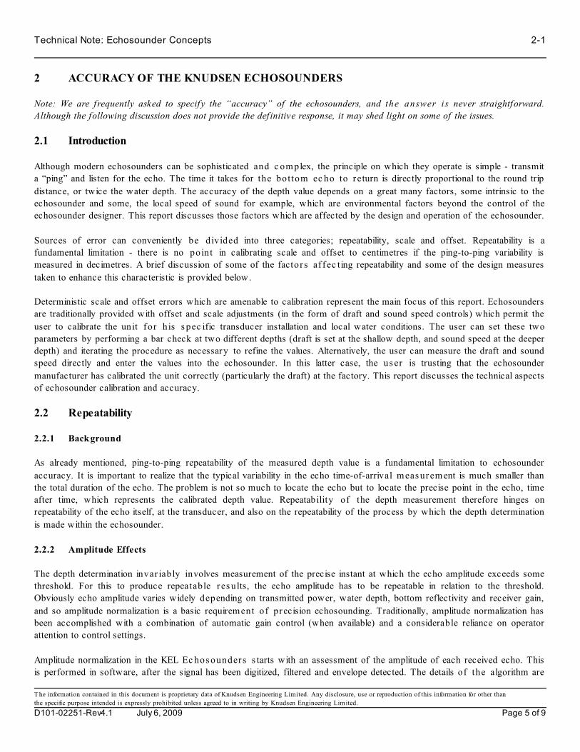
Technical Note: Echosounder Concepts 2-1
T he information contained in this document is proprietary data of Knudsen Engineering Limited. Any disclosure, use or reproduction of this information for other than
the specific purpose intended is expressly prohibited unless agreed to in writing by Knudsen Engineering Limited.
D101-02251-Rev4.1 July 6, 2009 Page 5 of 9
2 ACCURACY OF THE KNUDSEN ECHOSOUNDERS
Note: We are frequently asked to specify the “accuracy” of the echosounders, and the answer is never straightforward.
Although the following discussion does not provide the def initive response, it may shed light on some of the issues.
2.1 Introduction
Although modern echosounders can be sophisticated and c om plex, the principle on which they operate is simple - transmit
a “ping” and listen for the echo. The time it takes for the bottom ec ho to r eturn is directly proportional to the round trip
distance, or twice the water depth. The accuracy of the depth value depends on a great many factors, some intrinsic to the
echosounder and some, the local speed of sound for example, which are environmental factors beyond the control of the
echosounder designer. This report discusses those factors which are affected by the design and operation of the echosounder.
Sources of error can conveniently be divided into three categories; repeatability, scale and offset. Repeatability is a
fundamental limitation - there is no point in calibrating scale and offset to centimetres if the ping-to-ping variability is
measured in decimetres. A brief discussion of some of the factor s af f ec t ing repeatability and some of the design measures
taken to enhance this characteristic is provided below.
Deterministic scale and offset errors which are amenable to calibration represent the main focus of this report. Echosounders
are traditionally provided with offset and scale adjustments (in the form of draft and sound speed controls) which permit the
user to calibrate the unit for his s pec ific transducer installation and local water conditions. The user can set these two
parameters by performing a bar check at two different depths (draft is set at the shallow depth, and sound speed at the deeper
depth) and iterating the procedure as necessary to refine the values. Alternatively, the user can measure the draft and sound
speed directly and enter the values into the echosounder. In this latter case, the us er is trusting that the echosounder
manufacturer has calibrated the unit correctly (particularly the draft) at the factory. This report discusses the technical aspects
of echosounder calibration and accuracy.
2.2 Repeatability
2.2.1 Background
As already mentioned, ping-to-ping repeatability of the measured depth value is a fundamental limitation to echosounder
accuracy. It is important to realize that the typical variability in the echo time-of-arrival m eas urem ent is much smaller than
the total duration of the echo. The problem is not so much to locate the echo but to locate the precise point in the echo, time
after time, which represents the calibrated depth value. Repeatability of the depth measurement therefore hinges on
repeatability of the echo itself, at the transducer, and also on the repeatability of the process by which the depth determination
is made within the echosounder.
2.2.2 Amplitude Effects
The depth determination invar iably involves measurement of the precise instant at which the echo amplitude exceeds some
threshold. For this to produce repeatable r es ults, the echo amplitude has to be repeatable in relation to the threshold.
Obviously echo amplitude varies widely depending on transmitted power, water depth, bottom reflectivity and receiver gain,
and so amplitude normalization is a basic requirement of precision echosounding. Traditionally, amplitude normalization has
been accomplished with a combination of automatic gain control (when available) and a considerable reliance on operator
attention to control settings.
Amplitude normalization in the KEL Ec hos ounder s s tarts with an assessment of the amplitude of each received echo. This
is performed in software, after the signal has been digitized, filtered and envelope detected. The details of the algorithm are

2-2 Technical Note: Echosounder Concepts
T he information contained in this document is proprietary data of Knudsen Engineering Limited. Any disclosure, use or reproduction of this information for other than
the specific purpose intended is expressly prohibited unless agreed to in writing by Knudsen Engineering Limited.
D101-02251-Rev4.1 July 6, 2009 Page 6 of 9
beyond the scope of this report, but basically it involves increasing the sample frequency of the envelope record by a factor
of four with a cubic spline interpolation, and then cros s -c or relating the upsampled signal with a replica of the leading edge
of the expected echo (this is also part of the bottom-picking algorithm). T he c or relat ion peak is scaled to produce a very
accurate estimate of echo amplitude. Another filter is used with the correlation results to obtain the background noise level.
A threshold is then computed as a specified fraction of the echo amplitude (usually 50%). The point in the s ample record at
which the envelope signal crosses the threshold is computed using polynomial interpolation and floating point arithmetic.
The end result of this process is to dec ouple the depth measurement from both amplitude variations and sample rate
limitations.
2.2.3 Bottom Type
Different bottom types can affect not only the amplitude of the return echo but also its shape. A very smooth, f lat bottom
provides an almost specular reflection with a well defined leading edge and very little off-axis return. A rough bottom, on
the other hand, returns a considerable amount of off-axis scattering which tends to elongate the pulse and shift the point of
peak amplitude downward. Generally speaking, bottom type effects are more difficult to compensate in the design of the
echosounder than the simple amplitude effects mentioned above. The template-m atching correlation scheme used in the
Echosounders for both bottom picking and amplitude normalization is very effective in minimizing sensitivity to bottom type.
2.2.4 Sample Rate Effects and Truncation Noise
This repeatability is s ue is peculiar to digital echosounders. It refers to the errors which accumulate whenever a timebase
parameter is trunc ated or rounded off to the nearest sample interval or improperly interpolated. It ultimately places limits on
the achievable resolution and therefore the repeatability of the t ime delay measurement. In early designs it tended to show
up in the form of A/D converter sample-rate limitations. In modern echosounder designs it is more likely to be the result of
fixed-point arithmetic or poorly written software.
T he only practical solution to truncation and round-off noise is to use floating point arithmetic for all timebase related
computations, and to use continuous polynomial interpolation when working with time-sampled data. This is the approach
taken in all current releases of KEL software. Digital timebase errors are essentially nonexistent in KEL Echosounders.
2.2.5 Pulse Length Effects
If properly implemented, different transmit pulse lengths are matched to different receive f ilters, with short pulses matched
to wide bandwidth filters, and vice versa (there is very little point in transmitting a long pulse unless the receive filter has an
appropr iately narrow noise bandwidth). The “group delay” of an analog or digital filter is inversely related to the bandwidth
and can be quite considerable in a narrowband filter. Fortunately this is a deterministic effect and can be corrected (see the
section on offset calibration). A more fundamental repeatability issue arises from the s imple observation that long,
narrowband pulses have a much longer rise time than short, wideband pulses, and the threshold c rossing instant is more
sensitive to minor amplitude variations. This is just another way of stating the well-known fact that longer pulses provide
poorer range resolution than short pulses.
2.2.6 Frequency Effects
Hydrographic surveyors are well acquainted with the fact that low f requency sound penetrates soft sediments more readily
than high frequency signals. They are also aware that the bottoms of oceans, lakes and rivers are often characterized by one
or more layers of soft sediments (sometimes very soft, as in “fluff”, which may be more liquid than solid) overlying harder,
more acoustic ally opaque materials. Echoes are generated at the interface between substances of low acoustic impedance
(such as water) and higher acoustic impedance (sediment). An even greater acoustic impedance difference may exist between
buried layers of soft and hard sediment. A low frequency echosounder will often identify a buried layer of hard sediment as

Technical Note: Echosounder Concepts 2-3
T he information contained in this document is proprietary data of Knudsen Engineering Limited. Any disclosure, use or reproduction of this information for other than
the specific purpose intended is expressly prohibited unless agreed to in writing by Knudsen Engineering Limited.
D101-02251-Rev4.1 July 6, 2009 Page 7 of 9
the “real” bottom, while a two-channel echosounder will often detect the shallowest interface on the high frequency channel,
and a deeper layer on the low frequency.
If the digitized depth values are consistent under these conditions, the results with a tw o-c hannel echosounder can provide
useful information about the type of bottom. More often, the depth values “bounce” back and forth between one interface and
another, producing misleading data.
2.3 Scale Errors
Modern echosounders use extremely precise quartz crystal timebase control, so in theory calibration error in the scale
parameter (sound speed) is effectively zero and can safely be disregarded. In practice, the theoretically achievable accuracy
can be compromised by errors in the digital processing of timebase parameters, mostly as a result of fixed-point arithmetic
or truncation errors. However, this is a software issue, and is easily resolved with good programming practice and floating-
point arithmetic as used in the KEL Echosounders.
Note that the scale parameter calibration error referred to here is the accuracy of the correction applied to the depth value by
the echosounder to compensate for the speed of sound value entered by the user, either in the course of a bar check or from
a sound velocimeter. The depth accuracy still depends ultimately on the accuracy of the sound veloc ity value provided by
the user. In practice, errors in the sound velocity value account for virtually all of the scale effects on the accuracy of the depth
measurement.
2.4 Offset Errors
Errors in the offset (draft) parameter result of all of the sm all t ime delays built into the signal paths in the echosounder.
Because of the very wide bandwidth of the Sounder 1600 and Chirp 3200 analog front ends, the error resulting from analog
group delay is negligible (group delay is inversely proportional to bandwidth). The same can not be s aid for the group delay
through the digital filters, which may be considerable. Fortunately, the group delay of a digital f ilter is deterministic and can
be precisely calc ulated for any filter at any frequency. The group delay through a transversal bandpass or lowpass digital
filter depends on the sampling interval and the number of taps, and inversely with the bandwidth, and is a very straightforward
computation. The formula is somewhat different for the c or relation filters used with chirp signals, but the precision with
which the group delay can be calculated is the same.
This actually represents one of the big advantages of the digital signal filters used in the KEL produc ts , over the multiple
analog filters used in other “digital” echosounders. The group delay values of the digital filters are computed prec is ely in
software, and are com pens ated for in software. No “tuning” of pots or coils in individual echosounders is involved, and of
course software never drifts.
It should be noted that all of the digital filtering in KEL Echosounder s , for both CW and chirp signals, is performed with
transversal, or finite impulse response (FIR) filters which are unconditionally stable.
The two-way group delay of the transducer itself contributes a very small amount to this offset error, varying s lightly from
transducer to transducer (the lower the Q of the transducer the smaller the group delay).
2.5 Summary
To summarize the discussion above:
1) The scale error contributed by the echosounder is essentially zero. Scale accuracy is norm ally controlled by the
accuracy of the speed of sound value which is entered by the operator, either from a sound velocity instrument or in

2-4 Technical Note: Echosounder Concepts
T he information contained in this document is proprietary data of Knudsen Engineering Limited. Any disclosure, use or reproduction of this information for other than
the specific purpose intended is expressly prohibited unless agreed to in writing by Knudsen Engineering Limited.
D101-02251-Rev4.1 July 6, 2009 Page 8 of 9
the course of a bar check.
2) The offset error contributed by the echosounder is essentially zero, a result of the deterministic and highly predictable
nature of digital filters. The main sources of error are normally the stability of the draft measurement entered by the
operator (sensitivity to vessel motion), and a lesser contribution from the group delay of the transducer.
3) The repeatability errors contributed by the ec hos ounder are difficult to measure, because under normal operating
conditions they are dominated by instabilities in the propagation medium, which is of course outside the c ontrol of
the echosounder.

Technical Note: Echosounder Concepts 3-1
T he information contained in this document is proprietary data of Knudsen Engineering Limited. Any disclosure, use or reproduction of this information for other than
the specific purpose intended is expressly prohibited unless agreed to in writing by Knudsen Engineering Limited.
D101-02251-Rev4.1 July 6, 2009 Page 9 of 9
3 DIGITIZED DEPTH VERSUS PRINTED ECHOGRAM
We are often asked about discrepancies between the digital depth value and the pr inted ec hogram. Most often, the printed
echogram shows the leading edge of the bottom echo to be shallower than the digitized depth. This note addresses the reason
for this apparent discrepancy.
In the early days of ec hos ounders, before digitizers, the printed record was the only record. The hydrographer adjusted the
draft and sound speed during a bar check us ing the depths he scaled directly from the printed record, based on his visual
determination of the location of the leading edge of the echo. There were two problems with this approach. First, the
hydrographer would have noticed that the depth was slightly dependent on receiver gain . By cranking up the gain he could
“thicken” the bottom line and decrease the apparent depth slightly. Reducing the gain had the oppos ite ef f ect. Second, the
person who digitized the printed record back in the shop may have had a slightly different view of the precise location of the
leading edge of the echo - a bias toward a lighter or darker shade of grey as the threshold point.
Both of these problems result f rom the fact that the leading edge of the echo is not a distinct event. The echo arrives as an
increase in signal strength from the background noise level to the echo peak over a finite period of time. The rise time of the
echo has a minimum duration of about half the transmitted pulse length. To put this into perspective, the duration of the
leading edge of the echo from a 0.1 ms transmit pulse (a typical pulse length for high frequency shallow water work) is
equivalent to almost 4 centimetres of depth. The longer pulses used in deeper water have longer rise times. In prac t ic e,
however, the echosounder is more accurate than these rise times would lead us to believe.
In the days before digitizers, the easiest way to deal with the rise time problem was to operate the sounder with receive gain
increased to the point where the background noise just started to show, and the bottom echo was strongly saturated. This has
the effect of setting the detection threshold very low, almost at the nois e level, and it works well because the human brain
is very good at distinguishing echo from noise. The repeatability (and accuracy) of depths scaled by hand from such records
is typically a fraction of the nominal pulse length.
The digitizer software, on the other hand, is designed to set its threshold at the midpoint of the leading edge, at the 50%
amplitude point, because this is the value that provides optimum detection performance.
The problem is that hydrographers tend to set their visual threshold at the point in the echogram where the echo first becomes
visible, which is often somewhat shallower. The difference between the digitized depth and what the hydrographer sees on
the printed record is more pronounced at the high print contrast levels many users prefer, and with longer pulse lengths.
Two points are worth noting. First, the fact that the digitizer threshold is set at the 50% point rather than at some lower (but
still v is ible on the echogram) value does not mean that the echosounder has a built-in error equal to half the rise time of the
echo (or a quarter of the pulse length). In fact, the echosounder software accounts for this very precisely.
Second, the point at which the echo becomes visible on the echogram is highly dependent on the print contrast mode which
is us ed ( s ee the user manual for an explanation of these modes). With most print contrast modes (particularly including
manual contrast), the relationship between the greyscale echogram and the digitized depth is subject to interpretation.
In summary, the digitized depth is most likely correct, even if the printed record appears to be slightly shallower. This should
only be a matter for concern if the depth discrepancy is much greater than about a quarter of a pulse length.