sound advance r - abt electronics · sa sound advance r sa2 warranty sa2 limited warranty (united...
TRANSCRIPT

Page 1Installation Instructions 960.031 Rev # 2
SOUND ADVANCESA R
SA2 Warranty
SA2 LIMITED WARRANTY (United States & Canada only) Invisible Aesthetic Speakers
SOUND ADVANCE SYSTEMS, Inc. (sometimes referred to as “Sound Advance” or “SAS” ); hereby warrants to eachowner of the SA2 Loudspeakers during the term of this warranty, that:
1. If your SOUND ADVANCE SA2 loudspeakers are installed by a Certified SA2 Dealer/installer, recommendedprocedures. materials and techniques, the SA2 loudspeakers are covered by a FIFTEEN (15) year Limited Warranty, fromthe original date of purchase by the first buyer. This Warranty is transferable to a new owner of the dwelling containingsuch SA2 loudspeakers.
Should a SOUND ADVANCE SA2 loudspeaker fail during this 15-year warranty period. SOUND ADVANCE willreplace it at no charge, and will pay for (a) the labor to remove the defective loudspeaker, (b) return shipping costs, (c)labor to re-install the loudspeaker, and (d) except as set forth the next paragraph, restoration of the wall or ceiling surfaceto a condition as close as reasonably possible to the original. If permanent artwork covers the loudspeaker, then SASshall not be responsible for any damage to such artwork, and owner shall be responsible for restoring such artwork. If wallcovering, such as wallpaper or leather or unique products, covers the loudspeaker, then SAS shall not be responsible forcomplete restoration, but SAS may issue a replacement or reimbursement allowance to the owner on a case-by-casebasis.
2. If your SOUND ADVANCE SA2 loudspeakers are installed by a Non-Certified SA2 Dealer/installer, the SA2loudspeakers are warranted to be free from defects in materials and workmanship for a period of ONE (1) year from theoriginal date of purchase. During this warranty period, SAS will repair or replace (at its option) all such defects withoutcharge for parts or labor, if returned prepaid to the proper SOUND ADVANCE Service facility, together with the originalsales receipt or other proof of purchase. The units will be returned prepaid.
3. Should you require Warranty Service, please contact your Dealer/Installer. If further assistance is required, callSOUND ADVANCE SYSTEMS at 800-592-4644 (within U.S.) or 714-556-2378 8:00 A.M - 5:00 P.M. Pacific Time, or Fax at714-556-5425.
For a detailed warranty disclosure please refer to the SA2 Limited Warranty, included with the loudspeaker.
SOUND ADVANCE SYSTEMS, INC. - 3202 S. Shannon St.. Santa Ana, CA 92704-6353

Page 2 Installation Instructions960.031 Rev # 2
SOUND ADVANCESA R

Page 3Installation Instructions 960.031 Rev # 2
SOUND ADVANCESA R
ContentsSA2 Certified Installer Training ................................................................................................................................... 1
1 NEW CONSTRUCTION ................................................................................................................................. 41.1 Installing the PBB4 enclosure in between 16-inch on-center wooden stud framing prior to dry wall. .................. 41.2 Installing the PBB4 enclosure between 16-inch on-center metal stud framing prior to dry wall. ......................... 41.3 Installing the PBB6 enclosure into 24-inch on-center wooden Joist framing prior to dry wall. ............................ 51.4 Installing the PBB6 enclosure between 24-inch on-center metal joist framing prior to drywall. .......................... 71.5 Installing the PBB4 or PBB6 to framing prior to installation of double layer gypsum wallboard ........................... 9
2. EXISTING CONSTRUCTION ...................................................................................................................... 102.1 Installing the PBB4 between 16 inch on-center wooden stud framing after the installation of drywall. ............. 102.2 Installing the PBB4 enclosure between 16-inch on-center metal stud framing after the installation of drywall. 122.3 Installing the PBB6 between 24-inch on-center wooden Joist framing after the installation of drywall. ............ 142.4 Installing the PBB6 between 24-inch on-center metal Joist framing after the installation of drywall. ................ 172.5 Installing the PBB4 or PBB6 into Existing Lath and Plaster walls. ..................................................................... 202.6 Installing the PBB6 into Suspended drywall ceilings. ......................................................................................... 232.7 Installing the PBB4 or PBB6 in existing double layer gypsum wallboard construction. ...................................... 26
3. INSTALLING THE LOUDSPEAKER ............................................................................................................ 263.1 Installing the loudspeaker into PBB4 and PBB6 enclosures. ............................................................................. 26
4. FINISHING THE LOUDSPEAKER ............................................................................................................... 284.1 Finishing the Loudspeaker into Plaster Base or Treated Gypsum Wallboard with a 1/16” veneer plaster coat. 284.2 Finishing the loudspeaker into Standard Finished Drywall. ................................................................................ 31
5. REQUIRED TOOLS ..................................................................................................................................... 34Tools needed to install the SA2 loudspeaker. ........................................................................................................... 34
6. PRODUCTS CONTAINED IN THE SA2 PACKAGE. .................................................................................... 34SA2 packages and their contents: ............................................................................................................................ 34
APPENDIX ...................................................................................................................................................... 35
A. SETTING TYPE JOINT COMPOUND: ........................................................................................................ 35Manufacturer ............................................................................................................................................................. 35Product: .................................................................................................................................................................... 35Proper Use and Preparation of the Setting Type Joint Compound ........................................................................... 35Mixing Procedures .................................................................................................................................................... 35Application ................................................................................................................................................................ 35Joint Compound Cleanup .......................................................................................................................................... 35
B. OVERLAY ADHESIVE ................................................................................................................................ 35Manufacturer ............................................................................................................................................................. 35Surface Preparation .................................................................................................................................................. 35Mixing ....................................................................................................................................................................... 36Application ................................................................................................................................................................ 36Adhesive Cleanup ..................................................................................................................................................... 36
C. ADHESIVE PRIMER ................................................................................................................................... 36Manufacturer ............................................................................................................................................................. 36Application ................................................................................................................................................................ 36

Page 4 Installation Instructions960.031 Rev # 2
SOUND ADVANCESA R
1 NEW CONSTRUCTION
1.1 Installing the PBB4 enclosure in between16-inch on-center wooden stud framing prior todry wall.1. Retrieve the enclosure, leaving the corrugated cover
on until it is time to install the loudspeaker.
Note: If using a “Roto Zip” or drywall saw to removethe drywall at installation time remove the cardboardcover and save the insulation batt in a plastic bag forfuture use, to avoid damage to the tools.
2. Using a screwdriver, bend the hood of the knockouttowards the inside of the enclosure.
3. Pass the wire through the knockout hole, allowingapproximately 18 inches of wire to go inside theenclosure.
4. Using proper termination (saddle clamp) secure thewire to the enclosure.
5. Now you are ready to install the enclosure into theframing and secure using the 1-inch drywall screwsprovided.
1.2 Installing the PBB4 enclosure between16-inch on-center metal stud framing prior to drywall.1. Retrieve the enclosure, leaving the corrugated cover
on until it is time to install the loudspeaker.
Note: If using a “Roto Zip” or drywall saw to removethe drywall at installation time remove the cardboardcover and save the insulation batt in a plastic bag forfuture use, to avoid damage to the tools.
2. Using a screwdriver, bend the hood of the knockouttowards the inside of the enclosure. This is where theaudio wire will be routed from within the wall.

Page 5Installation Instructions 960.031 Rev # 2
SOUND ADVANCESA R
3. Now you are ready to install the enclosure into theframing and secure it using the 1-inch drywall screwsprovided.
4. Retrieve the audio wire and pass it through the knock-out hole, allowing approximately 1-foot of wire to goinside the enclosure.
5. Using proper termination (saddle clamp) secure thewire to the enclosure.
1.3 Installing the PBB6 enclosure into 24-inch on-center wooden Joist framing prior to drywall.1. For the enclosure to fit properly you will need to build
additional frame work between the existing 24-inch on-center framing, if the studs or joists are farther than 16inches apart.
2. Place a 24-inch long wooden stud up to the area thatwill be framed out.
3. Using a carpenters square, square up the new stud orjoist to the existing frame and secure it using 3-inchdrywall screws.
Page 6 Installation Instructions960.031 Rev # 2
SOUND ADVANCESA R
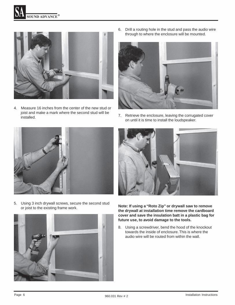
4. Measure 16 inches from the center of the new stud orjoist and make a mark where the second stud will beinstalled.
5. Using 3 inch drywall screws, secure the second studor joist to the existing frame work.
6. Drill a routing hole in the stud and pass the audio wirethrough to where the enclosure will be mounted.
7. Retrieve the enclosure, leaving the corrugated coveron until it is time to install the loudspeaker.
Note: If using a “Roto Zip” or drywall saw to removethe drywall at installation time remove the cardboardcover and save the insulation batt in a plastic bag forfuture use, to avoid damage to the tools.
8. Using a screwdriver, bend the hood of the knockouttowards the inside of enclosure. This is where theaudio wire will be routed from within the wall.
Page 7Installation Instructions 960.031 Rev # 2
SOUND ADVANCESA R
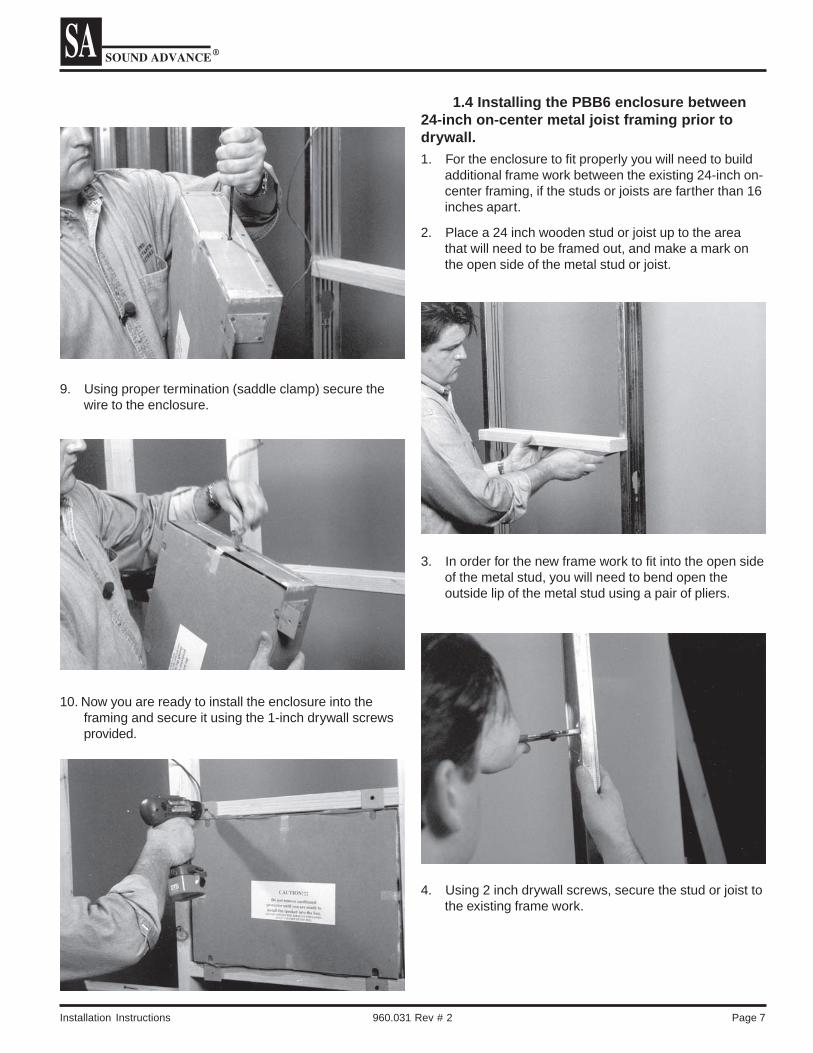
9. Using proper termination (saddle clamp) secure thewire to the enclosure.
10. Now you are ready to install the enclosure into theframing and secure it using the 1-inch drywall screwsprovided.
1.4 Installing the PBB6 enclosure between24-inch on-center metal joist framing prior todrywall.1. For the enclosure to fit properly you will need to build
additional frame work between the existing 24-inch on-center framing, if the studs or joists are farther than 16inches apart.
2. Place a 24 inch wooden stud or joist up to the areathat will need to be framed out, and make a mark onthe open side of the metal stud or joist.
3. In order for the new frame work to fit into the open sideof the metal stud, you will need to bend open theoutside lip of the metal stud using a pair of pliers.
4. Using 2 inch drywall screws, secure the stud or joist tothe existing frame work.
Page 8 Installation Instructions960.031 Rev # 2
SOUND ADVANCESA R
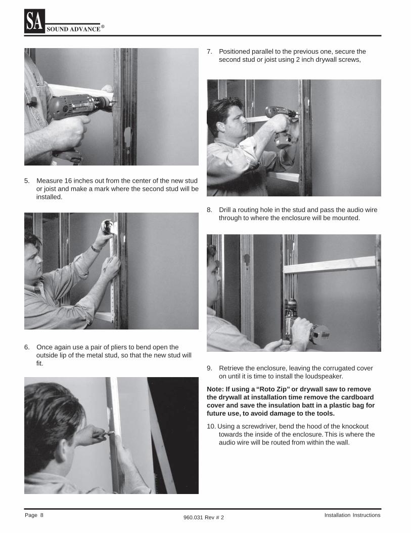
5. Measure 16 inches out from the center of the new studor joist and make a mark where the second stud will beinstalled.
6. Once again use a pair of pliers to bend open theoutside lip of the metal stud, so that the new stud willfit.
7. Positioned parallel to the previous one, secure thesecond stud or joist using 2 inch drywall screws,
8. Drill a routing hole in the stud and pass the audio wirethrough to where the enclosure will be mounted.
9. Retrieve the enclosure, leaving the corrugated coveron until it is time to install the loudspeaker.
Note: If using a “Roto Zip” or drywall saw to removethe drywall at installation time remove the cardboardcover and save the insulation batt in a plastic bag forfuture use, to avoid damage to the tools.
10. Using a screwdriver, bend the hood of the knockouttowards the inside of the enclosure. This is where theaudio wire will be routed from within the wall.

Page 9Installation Instructions 960.031 Rev # 2
SOUND ADVANCESA R
11. Retrieve the audio wire and pass it through the knock-out hole, allowing approximately 18 inches of wire togo inside of the enclosure.
12. Using proper termination (saddle clamp) secure thewire to the enclosure.
13P. Now you are ready to install the enclosure into theframing and secure it using the 1-inch drywall screwsprovided.
1.5 Installing the PBB4 or PBB6 to framingprior to installation of double layer gypsumwallboardNOTE: The adjustment screws in both the PBB4/6 willaccommodate a finish thickness of 1/2” through 5/8”,these are typical GWB (gypsum wall board) wall andceiling panels.
If the distance from the front of the PBB4/6 mount tabsto the final finish surface is greater than 5/8”, shimsmade of wood or GWB scrap must be placed betweenthe studs and the mounting tabs prior to securing it tothe studs.
1. Install shims of appropriate thickness between thestuds and mounting tabs of the PBB enclosure, prior tomounting the enclosure to the shim/stud assembly.
2. Retrieve the enclosure, using a screwdriver, removethe wiring knockout
3. Install a wire saddle clamp, pass the wire through theknockout hole, leaving 18” within the enclosure. Securethe wire saddle clamp.
4. Fasten the PBB4/6 to the shim/ stud assembly
5. If the PBB4/6 will be completely covered with GWBand will be removed at a later date using a Roto-Zip®or drywall saw at installation time, you must:
Tape the connection wire to the inside of the PBB4/6 toavoid damage from drywall tools.
Remove both the protective cardboard cover andinsulation material from the back box and store in aplastic bag for future use.
CUT-OUT
SHIMS
PBB4 or PBB6
Page 10 Installation Instructions960.031 Rev # 2
SOUND ADVANCESA R
2. EXISTING CONSTRUCTION
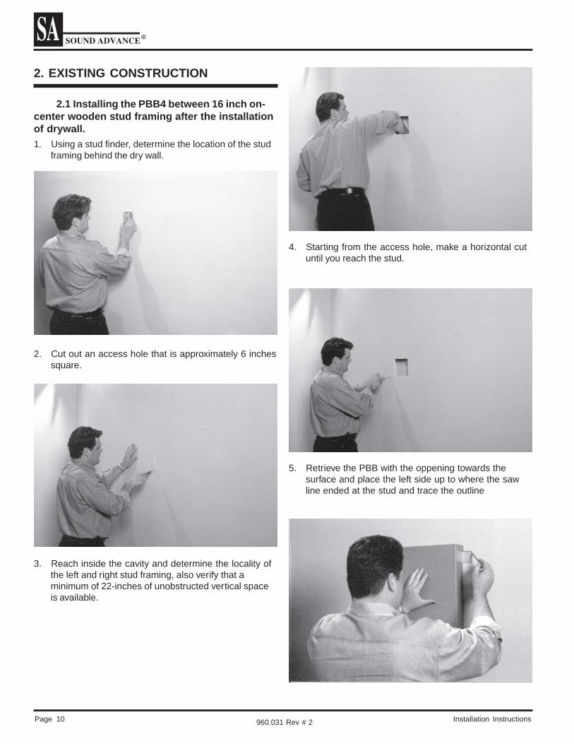
2.1 Installing the PBB4 between 16 inch on-center wooden stud framing after the installationof drywall.1. Using a stud finder, determine the location of the stud
framing behind the dry wall.
2. Cut out an access hole that is approximately 6 inchessquare.
3. Reach inside the cavity and determine the locality ofthe left and right stud framing, also verify that aminimum of 22-inches of unobstructed vertical spaceis available.
4. Starting from the access hole, make a horizontal cutuntil you reach the stud.
5. Retrieve the PBB with the oppening towards thesurface and place the left side up to where the sawline ended at the stud and trace the outline
Page 11Installation Instructions 960.031 Rev # 2
SOUND ADVANCESA R
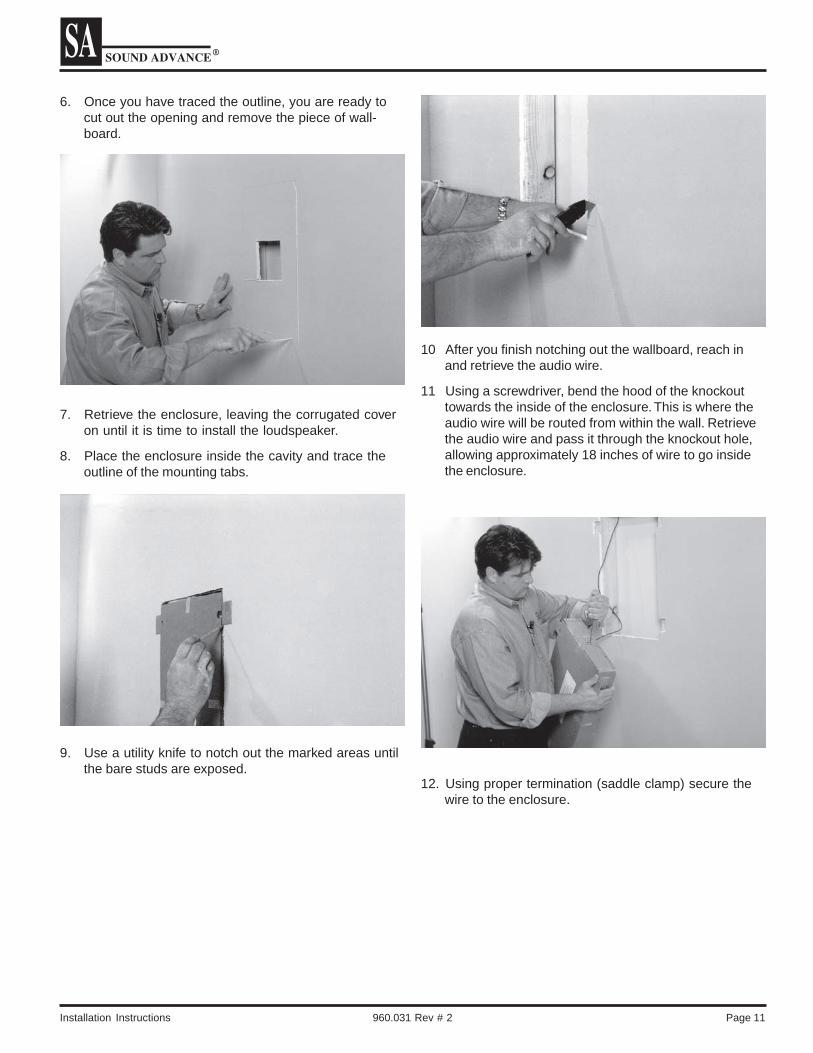
6. Once you have traced the outline, you are ready tocut out the opening and remove the piece of wall-board.
7. Retrieve the enclosure, leaving the corrugated coveron until it is time to install the loudspeaker.
8. Place the enclosure inside the cavity and trace theoutline of the mounting tabs.
9. Use a utility knife to notch out the marked areas untilthe bare studs are exposed.
10 After you finish notching out the wallboard, reach inand retrieve the audio wire.
11 Using a screwdriver, bend the hood of the knockouttowards the inside of the enclosure. This is where theaudio wire will be routed from within the wall. Retrievethe audio wire and pass it through the knockout hole,allowing approximately 18 inches of wire to go insidethe enclosure.
12. Using proper termination (saddle clamp) secure thewire to the enclosure.

Page 12 Installation Instructions960.031 Rev # 2
SOUND ADVANCESA R
13 Now you are ready to install the enclosure into theframing and secure it using the 1-inch drywall screwsprovided.
2.2 Installing the PBB4 enclosure between 16-inch on-center metal stud framing after the instal-lation of drywall.1. Using a stud finder, determine the location of the stud
framing behind the dry wall.
2. Cut out an access hole that is proximately 6 inchessquare.
3. Reach inside the cavity and determine the locality ofthe left and right stud framing, also verify that aminimum of 22-inches of unobstructed vertical spaceis available.

Page 13Installation Instructions 960.031 Rev # 2
SOUND ADVANCESA R
4. Starting from the access hole, make a horizontal cutuntil you reach the stud.
5. Retrieve the PBB with the oppening towards thesurface and place the left side up to where the sawline ended at the stud and trace the outline
6. Once you have traced the outline, you are ready tocut out the opening.
7. Retrieve the enclosure, leaving the corrugated coveron until it is time to install the loudspeaker.
8. Place the enclosure inside the cavity and trace theoutline of the mounting tabs.
9. Use a utility knife to notch out the marked areas untilthe bare studs are exposed.
10 Using a screwdriver, bend the hood of the knockouttowards the inside of the enclosure. This is where theaudio wire will be routed from within the wall.

Page 14 Installation Instructions960.031 Rev # 2
SOUND ADVANCESA R
11 Retrieve the audio wire and pass it through theknockout, allowing approximately 18 inches of wire togo inside the enclosure.
12. Using proper termination (saddle clamp) secure thewire to the enclosure
13 Now you are ready to install the enclosure into theframing and secure it using the 1-inch drywall screwsprovided.
2.3 Installing the PBB6 between 24-inch on-center wooden Joist framing after the installationof drywall.1. Using a stud finder, determine the location of the stud
framing behind the dry wall.
2. Cut out an access hole that is approximately 6 inchessquare.

Page 15Installation Instructions 960.031 Rev # 2
SOUND ADVANCESA R
3. Reach inside the cavity and determine the locality ofthe left and right stud framing, also verify that aminimum of 22-inches of unobstructed vertical spaceis available.
4. Starting from the access hole, make a horizontal cutuntil you reach the stud.
5. Retrieve the PBB with the oppening towards thesurface and place the left side up to where the sawline ended at the stud and trace the outline.
6. Once you have traced the outline, you are ready tocut out the opening and remove the piece of wall-board.
7. Retrieve the enclosure, leaving the corrugated coveron until it is time to install the loudspeaker.
8. Place the enclosure inside the cavity and trace theoutline of the mounting tabs.
9. Using a drywall saw, notch out the two traced areasthat have no stud or joist behind them.
10 Now, using a utility knife notch out the two remainingtraced areas on the opposite side.

Page 16 Installation Instructions960.031 Rev # 2
SOUND ADVANCESA R
11 At the edge of the long side of the opening, wherethere is no stud or joist, Install a 24 inch long woodenor metal stud (where required by code) behind the drywall.
12. Use 3 inch drywall screws to screw through thedry wall and into the 2X4.
13. Reach in the opening and retrieve the audio wire.
14. Retrieve the enclosure, leaving the corrugatedcover on until it is time to install the loudspeaker.
15 Using a screwdriver, bend the hood of the knock-out towards the inside of the enclosure. This iswhere the audio wire will be routed from withinthe wall. Retrieve the audio wire and pass itthrough the knockout hole, allowing approximately18 inches of wire to go inside the enclosure.
Page 17Installation Instructions 960.031 Rev # 2
SOUND ADVANCESA R
16. Using proper termination (saddle clamp) secure thewire to the enclosure.
17 Now you are ready to install the enclosure into theframing and secure it using the 1-inch drywall screwsprovided.
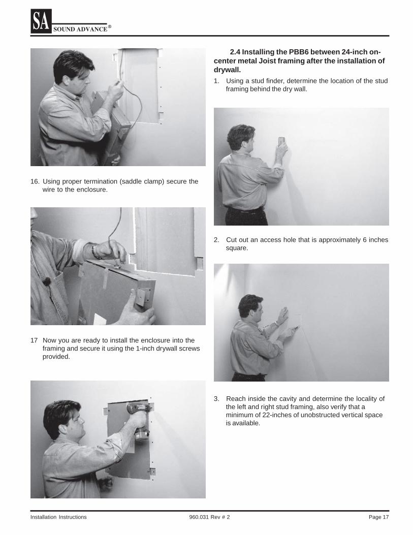
2.4 Installing the PBB6 between 24-inch on-center metal Joist framing after the installation ofdrywall.1. Using a stud finder, determine the location of the stud
framing behind the dry wall.
2. Cut out an access hole that is approximately 6 inchessquare.
3. Reach inside the cavity and determine the locality ofthe left and right stud framing, also verify that aminimum of 22-inches of unobstructed vertical spaceis available.

Page 18 Installation Instructions960.031 Rev # 2
SOUND ADVANCESA R
4. Starting from the access hole, make a horizontal cut,until you have reach the stud.
5. Retrieve the PBB with the oppening towards thesurface and place the left side up to where the sawline ended at the stud and trace the outline.
6. Once you have traced the outline, you are ready tocut out the opening and remove the piece of wall-board
7. Retrieve the enclosure, leaving the corrugated coveron until it is time to install the loudspeaker.
8. Place the enclosure inside the cavity and trace theoutline of the mounting tabs
9. Using a drywall saw, notch out the two traced areasthat have no stud or joist behind them.
10 Now, using a utility knife notch out the two remainingtraced areas on the opposite side.
Page 19Installation Instructions 960.031 Rev # 2
SOUND ADVANCESA R
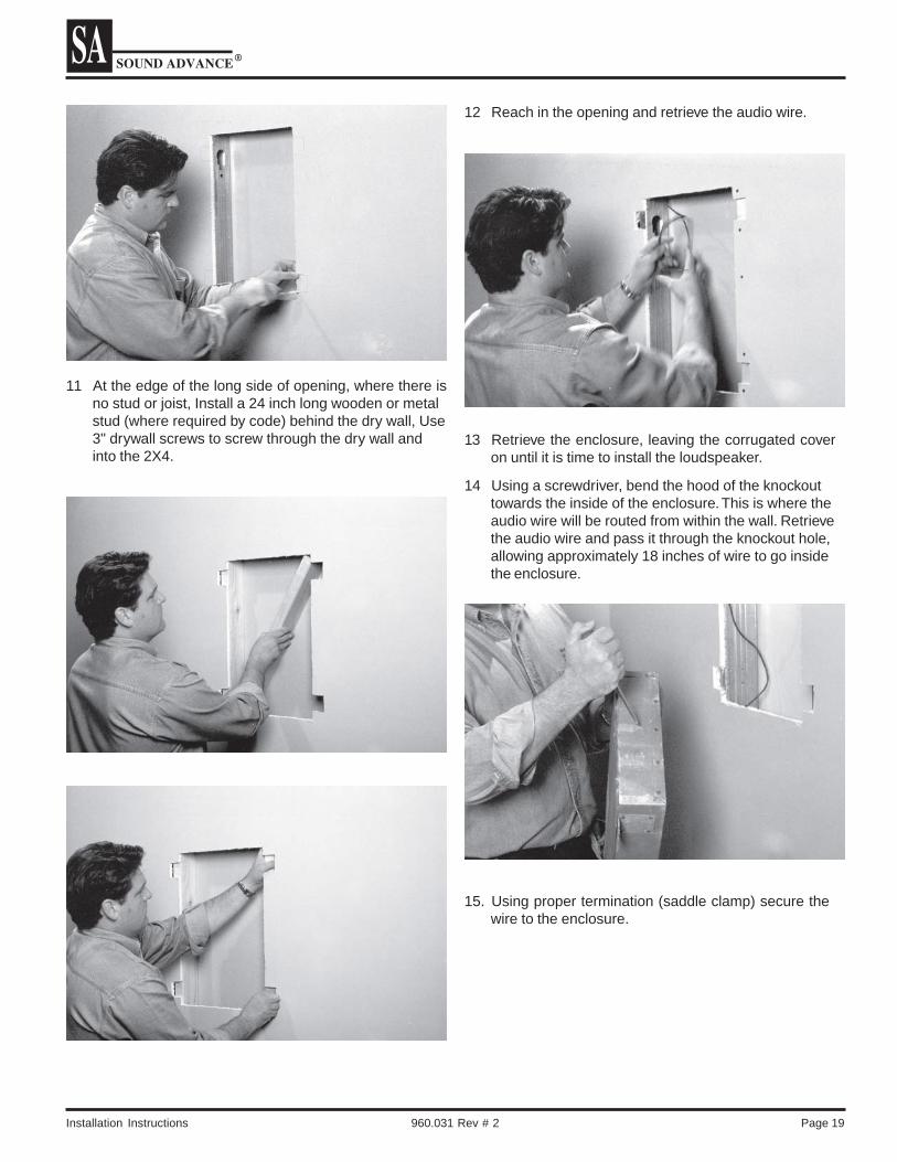
11 At the edge of the long side of opening, where there isno stud or joist, Install a 24 inch long wooden or metalstud (where required by code) behind the dry wall, Use3" drywall screws to screw through the dry wall andinto the 2X4.
12 Reach in the opening and retrieve the audio wire.
13 Retrieve the enclosure, leaving the corrugated coveron until it is time to install the loudspeaker.
14 Using a screwdriver, bend the hood of the knockouttowards the inside of the enclosure. This is where theaudio wire will be routed from within the wall. Retrievethe audio wire and pass it through the knockout hole,allowing approximately 18 inches of wire to go insidethe enclosure.
15. Using proper termination (saddle clamp) secure thewire to the enclosure.

Page 20 Installation Instructions960.031 Rev # 2
SOUND ADVANCESA R
16 Now you are ready to install the enclosure into theframing and secure it using the 1-inch drywall screwsprovided.
2.5 Installing the PBB4 or PBB6 into ExistingLath and Plaster walls.1. Using a stud finder, determine the location of the stud
framing behind the wall.
Note: Use caution when using a reciprocating saw inold wood lath and plaster. Use a fine toothed blade andwork slowly. In some cases a fine toothed blade in acircular saw will cause less vibrations and possibleless damage to existing work.
2. In order to get the saw blade into the lath and plaster,use a 1-1/4” wood drill bit and drill a hole in the wallbetween the left and right studs.
3. Using a reciprocating saw cut out an access holeapproximately 6-inches square.

Page 21Installation Instructions 960.031 Rev # 2
SOUND ADVANCESA R
4. Reach inside the cavity and determine the locality ofthe left and right stud framing, also verify that aminimum of 22-inches of unobstructed vertical spaceis available.
5. If the studs are farther then 16 inches apart, you willneed to center the opening between the left and rightstuds.
6. Retrieve the PBB with the oppening towards thesurface and place the left side up to where the sawline ended at the stud and trace the outline.
7. In order to get the saw blade in the wall, you will needto drill holes in two of the diagonal corners on thetraced border.
8. Using a reciprocating saw, begin to cut out theopening in the lath and plaster.
9. Once you have finished sawing, place the enclosureinside the cavity and then trace the outline of themounting tabs

Page 22 Installation Instructions960.031 Rev # 2
SOUND ADVANCESA R
10 Use the reciprocating saw to notch out the tracedareas.
11 At the edges on both long sides of the opening, installtwo 24 inch long wooden stud or metal stud(s) whererequired by local codes behind the lath and plaster.Use 3" drywall screws to screw through the lath andplaster and into the 2X4’s.
12 Reach up into the opening and retrieve the audio wire.
13 Retrieve the enclosure, leaving the corrugated coveron until it is time to install the loudspeaker.
14. Using a screwdriver, bend the hood of the knockouttowards the inside of the enclosure. This is where theaudio wire will be routed from within the wall. Retrieve

Page 23Installation Instructions 960.031 Rev # 2
SOUND ADVANCESA R
the audio wire and pass it through the knockout hole,allowing approximately 18 inches of wire to goinside the enclosure.
15. Using proper termination (saddle clamp) secure thewire to the enclosure.
16 Now you are ready to install the enclosure into theframing and secure it using the 1-inch drywall screwsprovided.
NOTE: The adjustment screws in both the PBB4/6 willaccommodate a finish thickness of 1/2” through 5/8”.If the distance from the front of the PBB4/6 mount tabsto the final finish surface is greater than 5/8”, shimsmade of wood or GWB scrap must be placed betweenthe studs or framing and the mounting tabs prior tosecuring it to the studs.
NOTE: If the retrofit will involve a plaster finish coat,read Section 4.1, Rev 960.068 Rev #2 , page 33 of thismanual to insure proper adjustment clearance for afinal plaster veneer coat.
2.6 Installing the PBB6 into Suspendeddrywall ceilings.1. Use a stud finder to determine the location of the metal
channels behind the dry wall.
2. Cut out an access hole approximately 6-inch square.
3. Reach inside the cavity and determine the locality ofthe left and right suspended metal channels, and verify
CUT-OUT
SHIMS
PBB4 or PBB6

Page 24 Installation Instructions960.031 Rev # 2
SOUND ADVANCESA R
that a minimum of 22-inches of unobstructed space isavailable in the long direction of the speaker.
4. If the metal channels are farther than 16 inches apart,you will need to center the opening hole so that it fallsin the middle, between the channels. Retrieve thePBB with the oppening towards the surface and placethe left side up to where the saw line ended at thestud and trace the outline.
5. Once you have traced the outline, you are ready tocut out the opening.
6. Retrieve the enclosure, leaving the corrugated coveron until it is time to install the loudspeaker.
7. Place the enclosure inside the cavity and trace theoutline of the mounting tabs
8. Use a drywall saw to notch out the traced areas.

Page 25Installation Instructions 960.031 Rev # 2
SOUND ADVANCESA R
9. At the edges on booth long sides of opening, Installtwo 24 inch long wooden or metal stud (where requiredby code) behind the dry wall . Use 3" drywall screwsto screw through the dry wall and into the 2X4s.
10 Reach into the opening and retrieve the audio wire.
11 Using a screwdriver, bend the hood of the knockouttowards the inside of the enclosure. This is where theaudio wire will be routed from within the wall.
12. Retrieve the audio wire and pass it through theknockout hole, allowing approximately 18 inches ofwire to go inside the enclosure.

Page 26 Installation Instructions960.031 Rev # 2
SOUND ADVANCESA R
13. Using proper termination (saddle clamp) secure thewire to the enclosure.
14. Now you are ready to install the enclosure into theframing and secure it using the 1-inch drywall screwsprovided.
2.7 Installing the PBB4 or PBB6 in existingdouble layer gypsum wallboard construction.
1. On the second, or outside layer of gypsum wallboard(GWB), determine the location of the loudspeakerinstallation by referring to steps 2.8.1 – 2.8.7.
2. Cut out and remove the traced areas only on thesecond or outside layer of GWB.
Install the PBB4/6 so that the mounting tabs rest onthe first or inside layer of GWB.
NOTE: The adjustment screws in both the PBB4/6 willaccommodate a finish thickness of 1/2” through 5/8”.If the distance from the front of the PBB4/6 mount tabsto the final finish surface is greater than 5/8”, shimsmade of wood or GWB scrap must be placed betweenthe studs or framing and the mounting tabs prior tosecuring it to the studs.
3. INSTALLING THE LOUDSPEAKER
3.1 Installing the loudspeaker into PBB4 andPBB6 enclosures.1. Using a utility knife, make a bevel cut and trim up the
edges of the dry wall, this will keep the paper skin ofthe dry wall from rolling up when sanding.
2. Remove the corrugated cover from the enclosure andtuck in the fiberglass insulation behind each of thebrackets located inside the enclosure.
LAYER2ND
LAYER1ST
CUT-OUT

Page 27Installation Instructions 960.031 Rev # 2
SOUND ADVANCESA R
3. Retrieve the rubber springs and note that they havebeen partially pre-cut by the factory to accommodatethe different thickness of dry wall. You will need to tearoff this piece if 1/4 or 1/2-inch dry wall is being used.
4. Install the rubber springs onto the four mountingbrackets.
5. Before placing the metal washers on the Allenscrews, use a rag to clean the threads so that thescrews are free from any dirt. This procedure willmake screws less likely to cross-thread.
6. Now strip the audio wires and connect them using 16gage wire nuts or solder. Check for line for continuitywith an audio signal from the source.
7. After you have connected the wires, place theloudspeaker into the enclosure and insert the Allenscrew through the hole in the speaker assembly,through the spring rubber and into the threadedfastener in the PBB. Use the key wrench provided totighten up the four Allen screws.
8. Tighten down the screws just enough to hold thespeaker in the enclosure.
9. Check the gap between the inside lip of the enclosureand the loudspeaker, if the gap is greater then a 1/4inch, fill the gap with silicone sealant. This procedurewill keep the joint compound from forming inside theenclosure and possibly breaking loose causing rattlesor buzzing to occur.

Page 28 Installation Instructions960.031 Rev # 2
SOUND ADVANCESA R
Take Care to insure that the RTV Silicone Sealantdoes NOT Get on the surface of the loudspeaker.
10 Cut out and remove any loose pieces of dry wall thatyou find.
11 Remove corrugated cover on the enclosure and adjustthe four Allen screws so that the surface of the loud-speaker is flush with the dry wall.
4. FINISHING THE LOUDSPEAKER
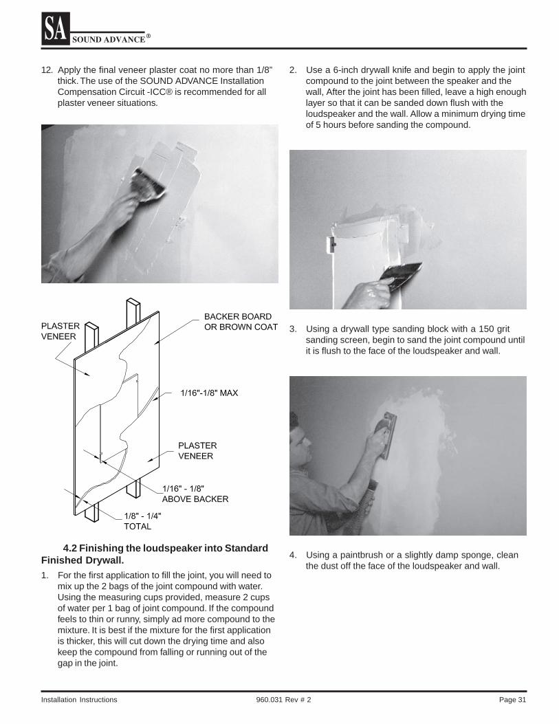
4.1 Finishing the Loudspeaker into PlasterBase or Treated Gypsum Wallboard with a 1/16”veneer plaster coat.NOTE: If the final veneer plaster coat is thicker than1/8”.The face of the loudspeaker should be adjusted outpast the surface of the unfinished plaster base ortreated gypsum board . This adjustment should allowthe loudspeaker to receive no more than 1/8” maxiumof veneer plaster.
1. Adjust the four Allen head screws so that the face ofthe loudspeaker is flush to- or slightly above theunfinished surface of the plaster base or treatedgypsum board- Refer to note directly above.
2. Using the supplied or recommended setting type jointcompound fill the joint so that the compound is flushwith the unfinished plaster base or treated gypsumboard.

Page 29Installation Instructions 960.031 Rev # 2
SOUND ADVANCESA R
3. Using a drywall type sanding block with a 150 gritsanding screen, sand the joint compound or plasteruntil it is flush with the face of the loudspeaker.
4. After you are finished sanding, go over the arealightly with a damp sponge and clean up any loosedrywall dust.
5. Retrieve a sheet of vellum and hold it up to the wall,covering the face of the loudspeaker evenly. Make apencil mark at each of the four corners of the overlay,this will give you a rough idea how far out you will needto spread the adhesive.
6. Using a 2 inch paint brush, apply a coat of AdhesivePrimer to the speaker surface and the surroundingarea inside of the pencil marks. This procedure willkeep the plaster from absorbing the entire amount ofoverlay adhesive causing the vellum to bubble or lift upfrom the plaster. The drying time can be accelerated byusing a hair dryer at a safe distance of 2 ft. from thewall. Place your hand palm down just skimming thesurface of the loudspeaker, if the dryer is too hot onyour hand , it is too hot for the speaker.

Page 30 Installation Instructions960.031 Rev # 2
SOUND ADVANCESA R
7. After the adhesive primer has dried, use a 2 inchpaint brush and apply a generous amount of overlayadhesive evenly within the pencil marks on the wall.
8. Using your hand apply the vellum overlay starting atthe center of the loudspeaker, gently working your wayout toward the edges. Use a 6 -inch hard plasticsqueegee or a taping knife and, once again, start atthe center, moving out past the edges, utilizing a goodamount of pressure.
9. With the first couple of passes, you will notice anexcess of adhesive on your squeegee, leaving theadhesive on will help you glide over the vellum withease and at the same time completely saturating thevellum with adhesive.
10 If the edges look like they are starting to come up,then simply peel up the paper and apply more adhe-sive.
11 Using a damp sponge, wipe the excess adhesive offloudspeaker surface and the surrounding area of thewall. Allow the vellum overlay to dry for a minimum of 2hours. It is very important that the overlay is completelydry before proceeding to the next step, The drying timecan be accelerated using a hair dryer at a safe dis-tance of 2 feet from the wall. Place your hand palmdown just skimming the surface of the loudspeaker, ifthe dryer is too hot on your hand , it is too hot for thespeaker.
Page 31Installation Instructions 960.031 Rev # 2
SOUND ADVANCESA R
12. Apply the final veneer plaster coat no more than 1/8”thick. The use of the SOUND ADVANCE InstallationCompensation Circuit -ICC® is recommended for allplaster veneer situations.
4.2 Finishing the loudspeaker into StandardFinished Drywall.1. For the first application to fill the joint, you will need to
mix up the 2 bags of the joint compound with water.Using the measuring cups provided, measure 2 cupsof water per 1 bag of joint compound. If the compoundfeels to thin or runny, simply ad more compound to themixture. It is best if the mixture for the first applicationis thicker, this will cut down the drying time and alsokeep the compound from falling or running out of thegap in the joint.
2. Use a 6-inch drywall knife and begin to apply the jointcompound to the joint between the speaker and thewall, After the joint has been filled, leave a high enoughlayer so that it can be sanded down flush with theloudspeaker and the wall. Allow a minimum drying timeof 5 hours before sanding the compound.
3. Using a drywall type sanding block with a 150 gritsanding screen, begin to sand the joint compound untilit is flush to the face of the loudspeaker and wall.
4. Using a paintbrush or a slightly damp sponge, cleanthe dust off the face of the loudspeaker and wall.
Page 32 Installation Instructions960.031 Rev # 2
SOUND ADVANCESA R
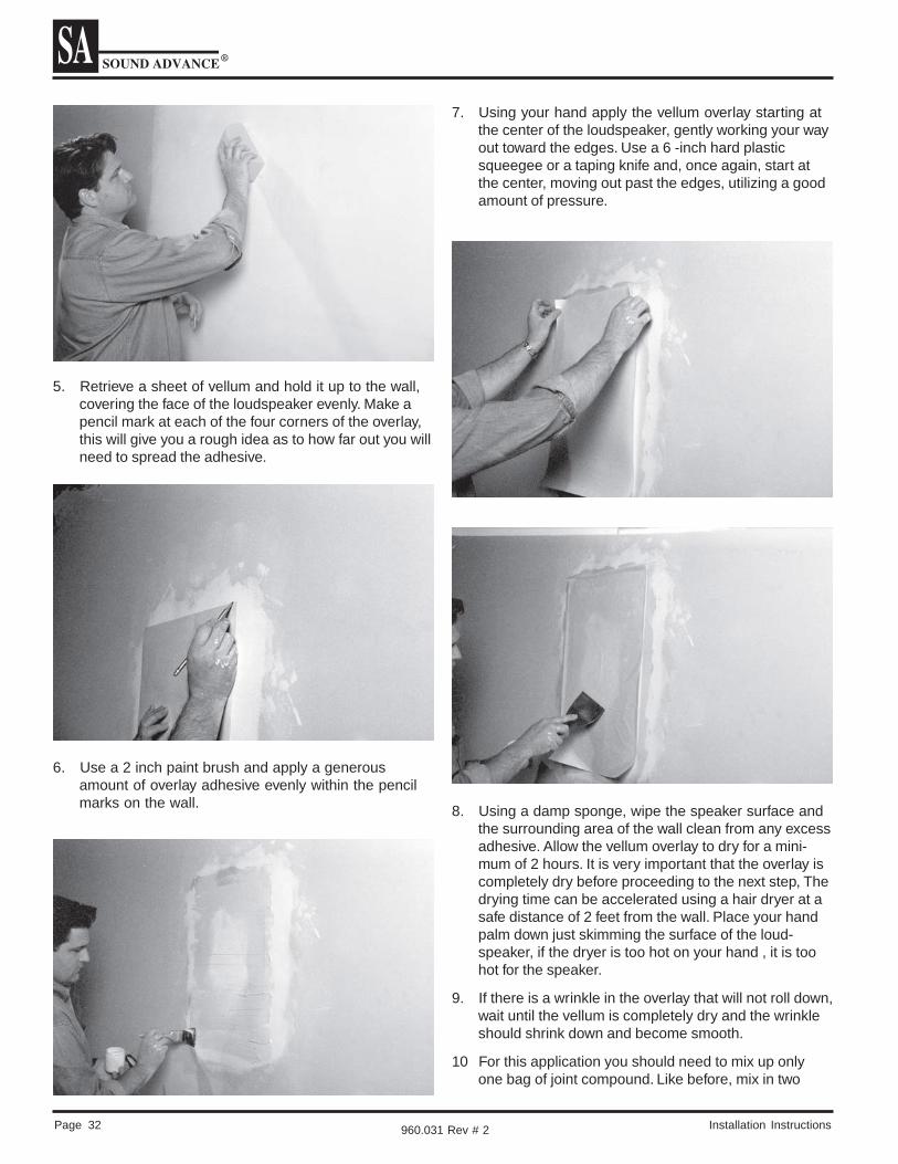
5. Retrieve a sheet of vellum and hold it up to the wall,covering the face of the loudspeaker evenly. Make apencil mark at each of the four corners of the overlay,this will give you a rough idea as to how far out you willneed to spread the adhesive.
6. Use a 2 inch paint brush and apply a generousamount of overlay adhesive evenly within the pencilmarks on the wall.
7. Using your hand apply the vellum overlay starting atthe center of the loudspeaker, gently working your wayout toward the edges. Use a 6 -inch hard plasticsqueegee or a taping knife and, once again, start atthe center, moving out past the edges, utilizing a goodamount of pressure.
8. Using a damp sponge, wipe the speaker surface andthe surrounding area of the wall clean from any excessadhesive. Allow the vellum overlay to dry for a mini-mum of 2 hours. It is very important that the overlay iscompletely dry before proceeding to the next step, Thedrying time can be accelerated using a hair dryer at asafe distance of 2 feet from the wall. Place your handpalm down just skimming the surface of the loud-speaker, if the dryer is too hot on your hand , it is toohot for the speaker.
9. If there is a wrinkle in the overlay that will not roll down,wait until the vellum is completely dry and the wrinkleshould shrink down and become smooth.
10 For this application you should need to mix up onlyone bag of joint compound. Like before, mix in two

Page 33Installation Instructions 960.031 Rev # 2
SOUND ADVANCESA R
measuring cups of water per one bag of joint com-pound. Apply the last coat of joint compound to theedges of the vellum and feather it out to the wall.
11 Once compound is dry, once more, lightly sand outuntil smooth.

Page 34 Installation Instructions960.031 Rev # 2
SOUND ADVANCESA R
MEASURING CUP (1)
(3)OVERLAY
(2)SA2
(4)JOINT COMPOUNT
(1)OVERLAY ADHESIVE
(8)RUBBER STANDOFF
FLAT WASHER (8)
(8)CAP SCREW
(1)HEX KEY
MEASURING CUP (2)
(5)OVERLAY
(4)SA2
(8)JOINT COMPOUNT
(2)OVERLAY ADHESIVE
(16)RUBBER STANDOFF
FLAT WASHER (16)
(16)CAP SCREW
(1)HEX KEY
5. REQUIRED TOOLS
Tools needed to install the SA2 loudspeaker.The following tools will be need to complete the
installation of the SA2 loudspeaker for all the differentapplications shown in this video.
• Cordless drill
• Phillips head screw driver
• Pliers
• Tape measure
• Utility knife
• Hammer
• Wire stripers
• Stud finder
• Electrical tape
• 12 inch mixing tray
• Drywall sanding block
• 1 inch putty knife
• 6 inch taping knife
• Hard plastic squeegee
• 2 inch paint brush
• Carpenters square
• 16 Gage wire Nuts
• Soldering kit
• Drywall Sanding block
• 150 Grit sanding screen
6. PRODUCTS CONTAINED IN THE SA2PACKAGE.
SA2 packages and their contents:2 Pack
4 Pack
Page 35Installation Instructions 960.031 Rev # 2
SOUND ADVANCESA R
APPENDIX
A. SETTING TYPE JOINT COMPOUND:
ManufacturerUnited States Gypsum Company - A subsidiary ofUSG Corporation
101 South Wacker Drive, Chicago, IL 60606-4385
Note: The Joint Compound may contain any or all ofthe following: Plaster of Paris, Calcium carbonate,Perlite, Mica, Clay or Polyvinyl acetate.
Product:Light Weight Setting Type JC 45'
Setting Time: 30 to 80 minute dependent upon tem-perature and humidity
Working Time: 15 to 20 minutes
Proper Use and Preparation of the SettingType Joint Compound
Mixing ProceduresMix Ratio: 10 fl. oz. of water per lb. of powder.
1. Use clean water and equipment
2. Mix powder and water in proportions indicated above(Initial mix should be slightly thicker than the desiredworking consistency)
3. Mix until smooth
4. Let mix stand for approximately 1 minute (The lowerthe temperature, the longer the material must stand)
5. Remix for 1 minute while adding water to achievedesired working consistency
CAUTION: Do not mix with other joint compounds inwet or dry form.
Do not re-temper mix.
Application1. Apply sufficient coats to level the surface; smooth
before setting begins.
2. Wait until preceding coat is hard before applying anadditional coat.
Joint Compound CleanupClean tools and containers immediately after use andbefore material hardens.
WARNING NOTICE
When mixed with water, this material hardens and thenslowly becomes hot. DO NOT attempt to make a castenclosing any part of the body using this material.Failure to follow these instructions may cause severeburns that may require surgical removal of affectedtissue. When mixing or dry sanding, dust may causeirritation to the eyes, noise, throat or upper respiratorysystem. Long term breathing of large amounts ofrespirable mica may cause lung disease. While mixingor sanding, wear a NIOSH approved dust mask. Do nottake internally. The use of safety glasses is STRONGLYrecommended.
NOTE: Setting time may vary somewhat due to geo-graphical variation in formulas. Setting cannot bealtered by dilution with water.
Product complies with ASTM C475
Emergency product safety information: 312/606-4542
Manufactured under on or more of the following U.S.Patents: RE 29,753- 4,454,267- 4,657,594- 4,686,253
B. OVERLAY ADHESIVE
ManufacturerCustom Building Products
Seal Beach, CA
Product: Standard Duty Clear -Wallcovering Adhesive
Working Time: Five (5) minutes or less
Surface PreparationSurface must be dry, clean, smooth, free of grease,wax and other foreign matter.

Page 36 Installation Instructions960.031 Rev # 2
SOUND ADVANCESA R
MixingStir adhesive thoroughly prior to application
Application1. Apply paste to the surface, not the overlay.
2. Apply an even coat to surface with a paste brush orshort nap paint roller.
3. Allow paste to soak in thoroughly.
4. Apply overlay to wall, position and smooth.
5. Immediately remove excess adhesive with smootherand a damp sponge.
Adhesive CleanupClean tools with warm, soapy water before adhesive dries.
NOTE: We do not recommend dilution with water.Keep from freezing. Close container after each use.
CAUTION :Keep out of reach of children Do not takeinternally
C. ADHESIVE PRIMER
ManufacturerJasco Chemical Corp.1008 Fuller StreetSanta Ana, CA 92701(714) 547-6951
ApplicationThe Adhesive primer is intended to be used in situa-tions where a skim coat of plaster is applied on thewall surface.
this application will seal the plaster surface and allowthe Overlay Adhesive to bond.
1. Apply paste to the surface of the wall and the speaker.
2. Allow to dry for a minimum of two hours. the dryingtime can be accelerated using a hair dryer at a safedistance of 2 feet from the wall. Place your hand palmdown just skimming the surface of the loudspeaker, ifthe dryer is too hot on your hand , it is too hot for thespeaker.
3. Once the Adhesive primer is dry, apply the OverlayAdhesive following the instructions in this InstallationGuide.
SOUND ADVANCESA R
SOUND ADVANCE SYSTEMS Inc.3202 So. Shannon St., Santa Ana, CA 92704-6353(714)556-2378 (800)592-4644 FAX (714)556-5425WWW.SOUNDADVANCE.COM

Page 37Installation Instructions 960.031 Rev # 2
SOUND ADVANCESA R
NOTES

Page 38 Installation Instructions960.031 Rev # 2
SOUND ADVANCESA R
NOTES
Page 39Installation Instructions 960.031 Rev # 2
SOUND ADVANCESA R
Page 40 Installation Instructions960.031 Rev # 2
SOUND ADVANCESA R

Page 41Installation Instructions 960.031 Rev # 2
SOUND ADVANCESA R

Page 42 Installation Instructions960.031 Rev # 2
SOUND ADVANCESA R