soporte universal articulado para tv’s de lcd, led y ... · support universel articulé pour tv...
TRANSCRIPT

Spanish
Articulating Mount FSA64
Universal Mount for LCD, LED & Plasma TV’s
Soporte Universal Articulado para TV’s de LCD, LED y Plasma Support Universel Articulé pour TV LCD, LED et Plasma
Soporte Universal Articulado para TV de LCD / LED / Plasma
Display Size: 30” ~ 60” Maximum load: 41 kg / 90 lbs VESA Patterns: 100 x 100 200 x 100 400 x 400 600 x 400 Tilt Range: -5 ~15˚
Inst
alla
tion
Inst
ruct
ions
2
SectionIT IS HIGHLY RECOMMENDED THAT THIS PRODUCT BE INSTALLED BY A PROFESSIONAL. PLEASE REVIEW THIS INSTRUCTION MANUAL COMPLETELY BEFORE STARTING THE INSTALLATION PROCESS.
WARNING: A WARNING alerts you to the possibility of serious injury or death if you do not follow the instructions. CAUTION: A CAUTION alerts you the possibility of damage or destruction of equipment if you do not follow the corresponding instruction. WARNING: Improper installation can result in serious personal injury! Make sure that the structural members can support a weight factor five times the total weight of the equipment. If not, reinforce the structure before starting the installation.
WARNING: Be aware also of the potential for personal injury or damage to the unit if it is not ad-equately mounted.
WARNING: The installer is responsible for verifying that the wall or ceiling to which the the mount is anchored will safely support the combined load of all attached components or other equipment.
WARNING: The weight of the display placed on the mount must not exceed the maximum load capac-ity of the mount.
WARNING: Watch for pinch points. Do not put your fingers between movable parts.
WARNING: Make sure the mount and brackets are correctly oriented.
CAUTION: Check the unit for shipping damage before you begin the installation.
Warnings & Cautions

3
1. This mount is intended for use with displays weighing no more than 90 lbs (41 kg). Use a of heavier display can result in damage or injury.
2. Make sure these instructions are read and completely understood before attempting installation. If you are unsure of any part of this installation, contact a professional installer for assistance.
3. The wall or mounting surface must be capable of supporting the combined weight of the mount and dis-play; otherwise the structure must be reinforced.
4. Safety gear and proper tools must be used. A minimum of two people are required for this installation. Failure to use safety gear and / or attempting this installation alone can result in property damage, serious injury or death.
5. Follow all instructions and recommendations regarding adequate ventilation and suitable locations for mounting your display. Consult the owner’s manual for your display for more information.
Parts
ID Qty DescriptionA 4 M4 x 16 mm boltB 4 M5 x 16 mm boltC 4 M6 x 16 mm boltD 4 M8 x 16 mm boltE 4 Square washerF 4 Lag bolt washerG 4 Lag boltH 4 Wall anchor1 1 Allen wrench2 1 Box wrench
A-D E F G
H 1 2
Bubble Level
Safety BoltBracket
TV Plate
Nut
Plastic Cover
Slide Block
Extension Plate
Bolt
Bolt
Wall Plate
4
Section
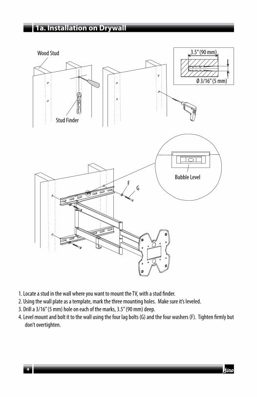
1. Locate a stud in the wall where you want to mount the TV, with a stud finder.2. Using the wall plate as a template, mark the three mounting holes. Make sure it’s leveled.3. Drill a 3/16” (5 mm) hole on each of the marks, 3.5” (90 mm) deep.4. Level mount and bolt it to the wall using the four lag bolts (G) and the four washers (F). Tighten firmly but
don’t overtighten.
1a. Installation on Drywall
Bubble Level
Wood Stud
Stud Finder
FG
3.5” (90 mm)
Ø 3/16” (5 mm)

5
1b. Installation on Concrete Wall
1. Using the wall plate as a template, mark the three mounting holes, where you want your TV to be mounted. Make sure it’s leveled.
3. Drill a 3/8” (9.5 mm) hole on each of the marks, 3.5” (90 mm) deep.3. Insert a concrete anchor (H) on each of the holes until they are flush to the wall.4. Bolt the mount to the wall using the four lag bolts (G) and the four washers (F). Tighten firmly but don’t
overtighten.
3.5” (90 mm)
Ø 3/8” (9.5 mm)
Bubble Level
Concrete Wall
FG
H

6
2 Mount the TV
1. Center bracket on the back of the screen.2. Attach bracket to screen using the apropriate bolts (A-D) and 4 square washers (E).3. Tighten firmly but don’t overtighten.
A-D
E
M8 bolt
M6 or M5 bolt
M4 bolt
7
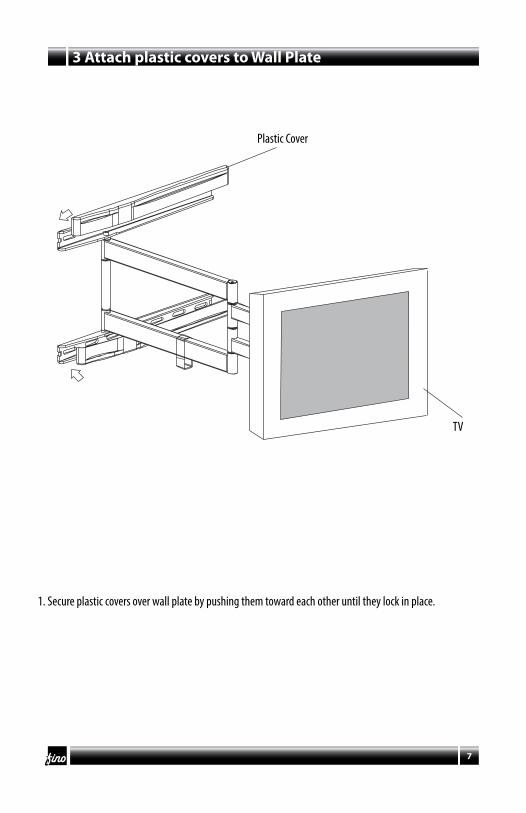
3 Attach plastic covers to Wall Plate
1. Secure plastic covers over wall plate by pushing them toward each other until they lock in place.
TV
Plastic Cover

8
Attach Adapter Extension to TV Plate (optional)
NutBold
Adapter Plate
Allen Wrench
Box Wrench
1. If using a mounting pattern bigger than the TV Plate (VESA 400x400), bolt the Adapter Plate Extension with its bolts and nuts and tighten using the the Allen wrench (1) and the Box wrench (2).
2. Tighten firmly but don’t overtighten.

9
Attach Brackets to Screen
M8 bolt
M6 or M5 bolt
M4 bolt
1. Center brackets vertically on back of screen. 2. Attach brackets to screen using the apropriate bolts (A-D) and 4 square washers (E).3. Tighten firmly but don’t overtighten.
A-DE

10
SectionMount the Screen
1. Hook the top of the brackets on the center of the adapter plate extension.2. Swing the screen down.3. Tighten the safety bolt on each bracket to lock the screen in place.Always use an assistant or mechanical lifting equipment to lift heavy weights.
4. Fix slide block into adapter with the screw.
Bracket
Slide Block
Adapter Plate
Safety Bolt
Bolt

11
Adjusting the Mount and Cable Management
1. Route the cables along the arm using the cable management clip.2. Arm tension can be adjusted by tightening or loosening the tension bolts. Do not overtighten or loosen to
the point where the bolts may come out.
Allen Wrench (1)
Tension Screw
-5˚ to 15˚
180˚180˚
Clip

Fino AV20218 Hamilton Avenue
Torrance, CA 90502USA
FinoTM name, logo and model numbers are property of Fino AV
©Fino AVTM
FOR MORE INFORMATION VISIT
www.finoav.com AUM052

English
Soporte ArticuladoFSA64
Soporte Universal para TV’s de LCD, LED y Plasma
Universal Articulating Mount for LCD, LED & Plasma TV’sSupport Universel Articulé pour TV LCD, LED et Plasma
Soporte Universal Articulado para TV’s de LCD / LED / Plasma
Tamaño de TV: 30” ~ 60”Soporte Máximo: 41 kg / 90 lbs
VESA: 100 x 100 200 x 100 400 x 400 600 x 400
Rango de Inclinación: -5 ~15˚
Inst
rucc
ione
s de I
nsta
lació
n
14
SectionES RECOMENDABLE QUE ESTE SOPORTE SEA INSTALADO POR UN PROFESIONAL.
POR FAVOR REVISE ESTE MANUAL Y FAMILIARÍCESE CON TODAS LAS HERRAMIENTAS Y PROCESOS ANTES DE EMPEZAR LA INSTALACIÓN.
ADVERTENCIA: Existe la posibilidad de una herida grave o muerte si no se sigue las instrucciones cor-rectamente.
PRECAUCIÓN: Existe la posibilidad de la destrucción total o parcial de un equipo si no se sigue las instrucciones correctamente.
ADVERTENCIA: Una instalación defectuosa puede causar heridas graves. Asegúrese que la pared tenga una capacidad de peso de cinco veces la capacidad total de la TV y soporte juntos. Si la pared no tiene la capacidad de peso requerida por favor refuerce la estructura de la misma.
ADVERTENCIA: El instalador tiene la responsabilidad de verificar que la pared o techo en donde va a ser montada esta unidad tenga la capacidad de peso requerida.
ADVERTENCIA: Existe la posibilidad de una herida o daño al equipo si el soporte es instalado de una forma no adecuada.
ADVERTENCIA: El peso del TV que va a ser instalado con esta unidad de brazo no puede exceder la capacidad máxima del producto.
ADVERTENCIA: Durante la instalación asegúrese de no poner sus dedos en uniones o en lugares donde se pueda lastimar.
ADVERTENCIA: Asegúrese que el soporte y todos sus componentes estén correctamente angulados.
PRECAUCIÓN: Verifique que esta unidad no tenga ningún daño que haya podido ser causado durante el transporte de la misma.
Advertencias y Precauciones

15
1. Este soporte esta diseñado para usarse con pantallas que pesan no más de 41 kg (90 lbs). El uso de unsoporte más pesado puede resultar en daño o una lastimadura.
2. Asegurese de leer y entender en su totalidad el estas instrucciones antes de empezar la instalación.3. La pared o superficie donde va a montar el soporte, debe ser capaz de sostener el total de carga de el soporte
y la pantalla; de lo contrario, debe ser reforzado.4. Equipo de seguridad y herramientas adecuadas deben ser usadas. Dos personas o más son requeridas para
la instalación. No seguir estas instrucciones puede resultar en daño al equipo, lastimaduras e incluso lamuerte.
5. Siga todas las instrucciones y recomendaciones sobre la adecuada ventilación y ubicación de su pantalla.Para mayor información consulte su manual.
Partes
ID Qty DescriptionA 4 Tornillo M4 x 16 mmB 4 Tornillo M5 x 16 mmC 4 Tornillo M6 x 16 mmD 4 Tornillo M8 x 16 mmE 4 Arandela cuadradaF 4 Arandela redóndaG 4 Tronillo de maderaH 4 Ancla para concreto1 1 Llave Allen2 1 Llave hexagonal
A-D
Nivel de burbuja
Tornillo de seguridadMénsula vertical
Placa de TV
Tuerca
Cubierta de plástico
Bloquedeslizable
Ménsula de extensión
Tornillo
Tornillo
Placa de muro
E F G
H 1 2

16
Section
FG
3.5” (90 mm)
Ø 3/16” (5 mm)
1. Con el localizador de vigas, localize las vigas donde desee instalar el soporte.2. Usando la placa de pared como plantilla, asegurese de que este nivelada y marque 4 orificios al centro de
la viga de madera. 3. Perfore 4 orificios de 3/16” (5 mm) diámetro y 2” (50 mm) de profundiad.4. Nivele el soporte y fije a la pared con 4 tornillos para madera (G) y las rondanas redondas (F). Ajuste los tornillos con firmeza, pero no apriete demasiado.
1a. Instalación sobre Tablaroca
Nivel de burbuja
Viga de Madera
Localizador de vigas

Nivel de burbuja
17
1b. Instalación sobre Concreto
1. Usando la placa de pared como plantilla, asegurese de que este nivelada y marque 4 orificios en el lugar deseado.
3. Perfore 3 orificios de 3/8” (9.5 mm) diámetro y 3.5” (90 mm) de profundiad.3. Inserte las anclas para concreto (H) en cada orificio hasta que esten al raz del muro.4. Nivele el soporte y fije a la pared con 4 tornillos para madera (G) y las rondanas redondas (F).
Ajuste los tornillos con firmeza, pero no apriete demasiado.
Muro de Concreto3.5” (90 mm)
Ø 3/8” (9.5 mm)
FG
H

18
2 Fije la TV
1. Centre la placa de TV detrás de su pantalla.2. Fije la placa con los tornillos apropiados (A-D) y 4 arandelas cuadradas (E).3. Ajuste los tornillos con firmeza, pero no apriete demasiado.
Tornillo M8
Tornillo M6 or M5
Tornillo M4
A-D
E

19
3 Instale las cubiertas de la placa de muro
1. Asegure las cubiertas sobre la placa de pared empujando una hacia la otra hasta que enganchen.
TV
Cubiertas

20
Instale las placas de extensión (opcional)
TuercaTornillo
Ménsula de extensión
Llave Allen
Llave hexagonal
1. Si necesita un patrón de montaje mayor (VESA400x400), instale las ménsulas de extensión apretando con la llave Allen (1) y la llave hexagonal (2).
2. Ajuste los tornillos con firmeza, pero no apriete demasiado.

21
Fije las ménsulas a la TV
1. Centre las ménsulas verticales en la parte de atrás de su pantalla.2. Fíjelas con los tronillos adecuados (A-D) y 4 arandelas cuadradas (E).3. Ajuste los tornillos con firmeza, pero no apriete demasiado.
A-DE
Tornillo M8
Tornillo M6 or M5
Tornillo M4
22
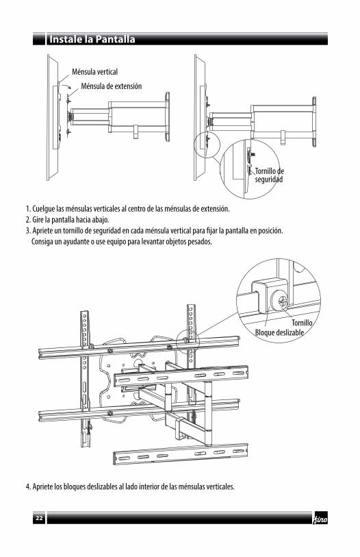
SectionInstale la Pantalla
1. Cuelgue las ménsulas verticales al centro de las ménsulas de extensión.2. Gire la pantalla hacia abajo.3. Apriete un tornillo de seguridad en cada ménsula vertical para fijar la pantalla en posición. Consiga un ayudante o use equipo para levantar objetos pesados.
4. Apriete los bloques deslizables al lado interior de las ménsulas verticales.
Ménsula vertical
Bloque deslizable
Ménsula de extensión
Tornillo de seguridad
Tornillo

23
Manejo de cables y ajustes
1. Pase los cables por los clips.2. La rigidez del brazo se puede regular apretando o aflojando el tronillo de tensión. No apriete demasiado o
afloje al punto que se caigan.
Llave Allen (1)
Tornillo de tensión
Clip
-5˚ a 15˚
180˚180˚

Fino AV20218 Hamilton Avenue
Torrance, CA 90502USA
El nombre FinoTM, logo y números de modelo son propiedad de Fino AV
©Fino AVTM
PARA MAYOR INFORMACIÓN VISITE
www.finoav.com AUM052