some eddy-current problems and their integral solutions
TRANSCRIPT


Contract; No. W-74CJ5 -eng-26
I%TALS 1zT\sD CERAMICS DIVISION
C , V. Dodd W. E. Deeds 5. W. Luquire W. G. Spoeri
APRIL 1969
OAK RIDGE NATIONAL L4BGRATDRY Oak Ridge, Tennessee
09 erat ed by W I O N CARBIDE CORPORATION
U. S. ATOMIC ENERGY CCMMISSIOfl for the
3 445b 0266736 0


i i i
CONTENTS
Page
Abstract . . . . . . . . . . . . . . . . . . . . . . . . . . . . . 1
1 . Introduction . . . . . . . . . . . . . . . . . . . . . . . . . 1
I1 . General Theory . . . . . . . . . . . . . . . . . . . . . . . . 4
A . D i f f e r e n t i a l Equation for t h e Vector P o t e n t i a l . . . . . . 4
5 . Superposition of Vector Poten t ia l s . . . . . . . . . . . . 4
C . Calculation of Various Electromagnetic Phenomena . . . . . 5
1 . Induced Voltage . . . . . . . . . . . . . . . . . . . G
2 . Mutual Inductance . . . . . . . . . . . . . . . . . . '7 3 . Self Inductance . . . . . . . . . . . . . . . . . . . 8 4 . Coil Impedance . . . . . . . . . . . . . . . . . . . . 8
6 . Induced Eddy Currents . . . . . . . . . . . . . . . . 12
'7 . Dissipated Power . . . . . . . . . . . . . . . . . . . 13 E? . Electromagnetic Forces . . . . . . . . . . . . . . . . 13
5 . Defects . . . . . . . . . . . . . . . . . . . . . . . 9
9 . Fourier Analyses of Nonsinusoidal Driving Currents . . l.5
I11 . Some Important Special Cases . . . . . . . . . . . . . . . . . 18 A . Coil above a Two-Conductor Plane . . . . . . . . . . . . . 18
1 . General Derivation . . . . . . . . . . . . . . . . . . 18 2 . Impedance of a Coil above a Two-Conductor Plane e . . 27 3 . Inductance of a Coil i n A i r . . . . . . . . . . . . . 24
4 . Defects i n the Cladding Material . . . . . . . . . . . 29
5 . Defects i n t h e Base Material . . . . . . . . . . . . . 30
6 . Eddy-Current Force . . . . . . . . . . . . . . . . . . 3 1
1 . Voltage and Phase of a Reflection-Type Coil . . . . . 33
Current Instrument . . . . . . . . . . . . . . . . . 36
3 . Defects i n t h e Cladding Material . . . . . . . . . . . 37 4 . Defects i n the Base Material . . . . . . . . . . . . . 38
1 . Voltage and Phase of a Through-Transmission Coi l . . . 39
I3 . Reflection Coi l above a Two-Conductor Plane . . . . . . . 33
2 . L i f t - o f f Compensation i n Yne Phase-Sensitive Edd;r-
C . Through Transmission . . . . . . . . . . . . . . . . . . . 33
2 . Defects i n a P l a t e . . . . . . . . . . . . . . . . . . 40

iv
Page
D . Coil between ‘Jho Conducting P la t e s . . . . . . . . . . . . . . . . . . . . . . . . . . . . . . I. . General Derivation
2 . lnipedance of a Coil between Two Conducting P la t e s . . E . Coil Encircling a Two-Conductor Hod . . . . . . . . . . . .
1. General Derivation . . . . . . . . . . . . . . . . . . 2 . Impedance of a Coi l Encircl-ing a Two-Conductor Rod . . 3 . Defects i n the Gu.‘ ier Mxterl’.al . . . . . . . . . . . . L+ . Defects i n the Inner Ma.teri.al 5 . Differentia.1. Coi.1 System . . . . . . . . . . . . . . .
E’. Coil . j-nside a Two-Conductor ‘Tube . . . . . . . . . . . . . 1 .. General Deriv-a*t,i.on . . . . . . . . . . . . . . . . . . 2 . . . .
. . . . . . . . . . . .
lnipedance of a Coil ins ide a Two-Conducto r. Tube 3 . Defects i.n t h e Inner Mater ia l . . . . . . . . . . . . L.. . Defects i n t h e Outer Material . . . . . . . . . . . .
N . Calcul.a.ted Results f o r Some Inipai-tant A_nplica’ij.ons . . . . . . V . Fqeri .mentaI Ver l f ica t ion . . . . . . . . . . . . . . . . . .
V I . Accuracy of Calculations . . . . . . . . . . . . . . . . . . . A . Axial Symmetry . . . . . . . . . . . . . . . . . . . . . . 9 . Current Sheet Approximation . . . . . . . . . . . . . . . C . iii.gh Frequency Effects . . . . . . . . . . . . . . . . . .
1 . The Skin Effect . . . . . . . . . . . . . . . . . . . 2 . Interwinding Capacitance . . . . . . . . . . . . . . .
4 = Displacemen-t Current Ef fec t . . . . . . . . . . . . . 5 . Assumption of Linear Media. . . . . . . . . . . . . . .
VIT . Conclusions . . . . . . . . . . . . . . . . . . . . . . . . . VI1 1 . Acknowl.ed.,gnen ‘is . . . . . . . . . . . . . . . . . . . . . . .
Appendix . . . . . . . . . . . . . . . . . . . . . . . . . . . . .
3 . C o i . 1- t o - . S amp l e C apa c it an c e . . . . . . . . . . . . . .
41
i t 1
46
47 &1
56
56
57 58
61-
61
67
67
68
68
‘13
78
‘I G 78 ‘79
79
80
81.
81
132
82
82
85

SOME EDDY-CURRENT FROBLENS AJTD THEIR I?TTEGR!-L SOLIPTIONS
C. V. Dodd W. E. Deeds' J. W. Luquire' W. G. Spoeri
Abstract
We have obtained integral representations for the vector potential produced by a circular coil for a number of different geometrical configurations. From the vector potential we can calculate any observable electromagnetic induction phenomenon. Our present solutions are limited to cases with axial symmetry and linear media. are in the form of multiple integrals of ordinary- and rnodi- fied Bessel functions.
The configurations that we have already solved include coils with rectangular cross sections in the followilzg loca- tions: above or on each side of a twO-ConduCtGr sheet bounded by parallel planes, between two parallel-plane conductors, encircling a tube or a rod consisting of one metal clad on another, and inside a tube. The electromagnetic phenomena that we have calculated include the coil impedance, the phase and amplitude of the voltage induced in pickup coils, the effects of small spheroidal defects on the impedance and. phase, and the forces generated in a metal. by the eddy c w - rents. is excellent in most cases and within experimental e r ro r in all cases.
The solutions
The agreement between calculated and lneasured pherromena
I. Introduction
One of the most important factors in any eddy-current test and one
of the most difficult to analyze is the coil- that generates the eddy
currents.
flowing in a circular coil in the presence of' a conducting material is
generally quite complicated.
times in the past by use of various physical models.
The electromagnetic field produced by an alternating current
The problem has been analyzed a nimber of
The solutions have
'Consultant from the University of Tennessee, Knoxville.
L
grad.i.m.l_lry become more a c c l r a k and 'ihe models more sophis t icated as the
a c t u a l problem i s bettei. approaillied.
very compli.cated solut ions, some of which are presented heye I
'Todhy w e have very accurate but
An ea r ly seri-es of paper by Forster2-" between 19.52 and 1754
deal t with both .the t'neory and p r a c t i c a l aspects of eddy-cwt-z-ent t e s t i n g .
Iie arialyzed a c o i l above a conducting pl.meJ a:;swning t h e c o i l t o be
a magnetic d.?::pole, and a?? i n f i n i t e c o i l enc i rc l ing an i:nfini-Le rod. I - io~hsch i ld~ i n 1959 al.so gave an ana lys i s of an i n f i n i t e c o i l and
Lnchxied- some eddy-current di-strtbii t ions i n the m-etal. Waidelich and
Renkt.n6 i n 1956 analyzed c o i l i.rrped.a,nce by an iiimge aI3prosch.
theore tical. results agreed wel.1 w i t h experiment f o r r e l a t i v e l y high
frequencies.
coil. was a transformel- with a network tied t o t he secondary. ne1;work representat ion gave good r e s u l t s when coqa-red t o experi.rr1en.t
The d i f fus ion o f eddy-current pulses (Atwood and, Libby,
Their
T,i-?7by7 i n 1.959 pre:;enf;ed a theory i n which he assumed -the
'This
1963) can be rep:ce,i;ei_ited i n t h i s manner. In 1962, Russell, Schuster, aad Waidklich, 9
assuming t h a t t he flux was e n t i r e l y coupled i n t o the conductor, analyzed a ciij?-core c o i l . The semieiiqirical r e s u l t s agreed fa3.rI.y T A r e 7 . l with the
'F.L.ied.riclz FErstes-, ---_- Z , Meta1.1.k. & - 163-.1.?1. (1952) . 3 F r i e d ~ i c h Fijrster and K u r t Stanibke, Z . Metallk. 45 ( 4 ) , 166-179
(1954).
'*Friedrich Forster , Z. Metallk. 45 ( L ; - ) , 197-199 (1954).
511. I-IocbschJ.l.d, "Electroni~g:l_etic Met'ilods of Testing Metals, " -
Progmss i n Nondestructive 'lkstirig9 --I- Vol. 1, Macmillan Company, New York, 1959.
6D. L. Waidelich and C. J . Redcen, Proc. N a t l . Electron Conf. 12, 186-196 (1956) .
9T. J. Russell , V. E. Schuster, and D. L, Waidelich, J. Electroz-. Control 13, 232-237 (1962). --___I =

3
experimental measurements.
Burrows'' i n 1964 gave treatments based on delta fbnct ion co i l s , and
Burrows continued with t h e development o f an eddy-em-rent f l a w theory
Dodd and Deeds13 i n 1363 and DoddL4 i n 1965 gave 3 re laxa t ion theory
t o ca l cu la t e t h e vector p o t e n t i a l o f a c o i l with a f i n i t e cross secti-on.
While t h e re laxa t ion theory i s v e ~ j v e r s a t i l e and quite accurate f o r a very f i n e l a t t i c e , it, requi res a l a rge d i g i t a l computer and i s very
expensive t o use. Dodd" i n 1967 and Dodd and Deedslb i n 1968 devel-
oped a s e t of i n t e g r a l equations t h a t can be evaluated accurately on a s m a l l computer. Un€ortunately, t h e der iva t ion of these equations i s complicated and m u s t be repeated for various c o i l and conductor configu-
r a t ions .)
Vein'' i n 1962, Chengl' i n 1364, and
This repor t presents t h e r e s u l t s f o r six cases of p r a c t i c a l
importance with some experimerkal v e r i f i c a t i o n of t h e ca lcu la t ions .
For the computer programs used i n evaluating the various formulas,
r e f e r to G'ne work by Luquire, Dodd, Deeds, and Spoeri."'
lop. R. Vein, J. El-ectron. Control - 13, 471-4'34 (1962).
"David H.S. Cheng, "The Reflected Impedance of a Circular Coi l in t he B o x i ~ t y of a Semi-lnfinite J!/iediwn," Ph.D. Ei.sserta-tion, University of Missouri, 196C;.
University Microfilms, Inc., Ann Arbor, 'Michigan, 19G:L+ .
'by a Relaxation Method," pp. 3C)0-%1~+ in Proceedings of the Symposium on Physics and Nondestructive Testing, Southwest Research I n s t i t u t e , San Antonio, Texas, 196.3.
12Ni.chael Leonard Burrows, A Theory of Eddy Cl.rrrent Flaw Detect?%,
1 3 C . V. Dodd arid W. E:. Deeds, "Eddy Cixlrrent Impedance Calcu1a.ted
I 4 C . V. Dodd, A- Solution t o Electromagnetic Induction Problems, ORNL-TM-llE?5 (1%5] and M. S. Thesis, the Universi ty of Tennessee, l%5.
15Cs V. Dodd, Solutions t o Electromagnetic Induction Problems, OIWL- ,T!M-1€Vv2 (19157) and Ph.D. Disser ta t ion , the University of Tennessee, 146'1.
"CC. V. Dodd and W , E. Deeds, J . Appl. Pkljrs. _I 3'9, 2i)29-2838 (1966). - '17J. W. Luqurire, C. V. Dodd, W. E. Deeds, and W. G* Epoeri, Csmputer
Programs f o r Some Eddy Current Problems, ORNLTM-2502 ( i n p r e p a r m

11. General Theory - For the cases considered here, the vector p o t e n t i a l adequately and
convenient.ly represents the electromagnetic f i e l d . I n this section we
s h a l l gi.ve the d i f f e r e n t i a l equation f o r the vector po ten t i a l of a s ingle
loop of wire, show how a number of simi-lar vector po ten t i a l s c3.n he
superimposed t o obtain the vector p o t e n t i a l for c o i l s of rectangular
cross secti-on, and then der ive equations f o r various physical. phenomena
i n terms of t he vector po ten t ia l .
A. Di f fe ren t ia l Equation for tile Vector Po ten t i a l -_m ._.__-
We s h a l l assume t h a t space i s divided irito regions of l i nea r , iso-
t rop ic , and homogeneous media, one of which contains an i n f i n i t e l y t h i n
c o i l caryying curwmt, r . s inusoidal currcnt i n the coi 1, whjch i s located at, (ro, z a ) i n cylindri-
cal coordinates.
We s h a l l a l s o assume a x i a l syrmetry and 3
'The d i f f e r e n t i a l eqimtioii for the spatial p a r t of the vector poten-
t i a l , A, is15
The soluti.on of t h i s d j - f f e ren t i a l equ-ation i s Q boundary value
problem, and it wi1J . be effected f o r varri oils geonetr:i.cal configirat ioi is
i n l a t e r sections.
u1a.r coilductor configuration has been solved, any number of d e l t a
f u i c t i o n c o i l s can then be superimposed t o bui ld up sny desired sliape
of c o i l .
Once t h i s l i n e a r d i f f e r e n t i a l equation f o r a p a r t i c -
B. Superposition of Vector ..-.__.I_ Poten t ia l s ... . ____--
We can w r i t e f o r " c ' n e to-Lal vector po-Lential produced a t ( r , z ) by
the su.perposit ion of n coaxi.al d . e l t a function c o i l s located a t 1" and z, i 1 n

5
Tnis equation i s va l id f o r c o i l s of any cross section. If we l e t
t he current , I, i n t he d e l t a funct ion c o i l s approach a continuous cur- r en t d i s t r i b u t i o n of dens i ty i o ( ' , ~ ) , then the vector p o t e n t i a l due t o
t h i s current w i l l also approach a continuous d i s t r ibu t ion .
dens i ty of t h i s vector p o t e n t i a l d i s t r ib lAion by plo( r , z , r o , z o ) , we can
mite t h e i n t e g r a l form of Eq. (2.2):
Denoting the
since Ao(r,z,~D,z,,) i s proport ional t o i o ( r , z ) , it w i l l prove useful-
for cases i n which the cur ren t i n each loop has the same magnitude and
phase t o express Eq. In such a
ease,
(2 .3 ) i n terms of the current densi ty .
nT i o ( r , z ) = = eonstant ,
(coi.1 area)
where I i s now the curren t i n each loop of wire.
MultLplying the integrand of Eq. (2 .3 ) by i o ( r , z ) / i o ( r , z ) and
making use of Eq. ( 2 . 4 ) y ie lds
(2 . I >
where we have a-ssumed t h e c o i l t o have a rectangular cross sect ion, a s
shown i n Fig. 1.
partj-cular c o i l and conductor configurat ion, the t o t a l vector p o t e n t i a l produced by a coil. with rectangular cross sec t ion may be obtained simply
by allowing the delta funct ion cur ren t t o approach t h e current density,
t, ,(r,z), and nfilring use of Eq. ( 2 . 5 ) .
Once the vector p o t e n t i a l has been calculated fo r a
C. Calculat ion of Various Electromagnetic Phenomena
Orice the vec tor p o t e n t i a l has been determined, any electromagnetic
induction phenomenon can be ca lcu la ted *om it. In this sec t ion we

6
ORNL-DWG 58-fO309
Fi.g. 1. A Rectangular Cross-Section Coil..
sha l l give the equations for the piienomens tha’i are of p a r t i c u l a r inLerest
t o the nolidestructive t e s t e r .
1. Induced Voltaae
We have, for the vol tage induced i n a l eng th of w i r e ,
For an a x i a l l y symmetric c o i l wit‘n 3. single loop o f raditis r,
Eq. ( 2 . 5 ) becomes
The to.tal. voltage induced in. a c o i l o f ?I turns is then
n ~~ ~.
v = j 2 m j L r i ~ ( r i , z i ) . i:-- 1
(2.8)

7
W e can 3pproxima.te t h e above summation by an integral over a turn
dens i ty of N turns per unit cross-sectional area:
V -2 j 2 n w J rA(r,z) Ndrdz . c o i l
c ross sec t ion
For c o i l s with a constant number of t u rns per u n i t c ross -sec t iona l a rea
rA(r,z) drdz . J J j2m.m v = c o i l c ros s sec t ion coil
cross sec t ion
If we spec i fy a rectangular cross-sect ion co 1 of length ( 4 ; -
sad of inner and outer radii r; and r;, respect ively, w e can w v r i k e
Ey i n s e r t i n g the vector p o t e n t i a l from E q . ( 2 . 5 ) i n t o Fq. (2 .11) , we
obtain t h e vol tage induced i n a c o i l (with primed parameters) by a
current , I, flowing i n a, coaxia l c o i l :
(2.19)
(2.11)
For t h e specj.a,l case of the self-ind.uced voltage, w e have
v =
2 .
l i .e,,
Mutual Indilc t anc e
(2.13)
The vol tage generated i n a '*pickup" c o i l with d-imensions r;,
by a current , I, flowing i n a "dr iver" coil with dimensions 1 2
a, is

8
or
(2.14)
Using Eq. ( 2 . 1 2 ) t o ca l cu la t e t h e vol tage we have
(2.15)
This is the mutual inductance between the dr ive r coil. and the pickup
c o i l . By the reciproci-Ly t711e0~ern, this i s equal. t o the muti~.al. inductance
betweei? the pickup coil. and t h e dr iver coil..
3 . Self Ind.ucta~ice
'The coI .1 . '~ self indue-Lance i s a spec ia l case of the mutual. i.nduc-
.Lance. We s h a l l let; the ~ W C ? c o i l s become one and the same and drop the
prFmes i n Eq. (2.15), obtaining
4 . C o t 1 Impedance
From tile self-induced voltage, we can ca l cu la t e t h e coi.1 impedance:
or
V z = - I
(2.17 1

Subs t i t u t ing f r o m Eq. (2.11) for -the self-indmed vol tage gives
The c o i l impedance i n t h e presence of a conductor i s usually normalized
by dividing it by the nagnitude of the c o i l impedance in air.
' c onduc t os
/'air Z Z
I n
Q1 r, z = n
5 . Defects
(2.19 ;,
Once we k n o w the vector p o t e n t i a l i n a metal, we c m determine the e f f e c t of a defect. defec t by the sum of a "ciurent defect" and a "magnetric: defec t . "
cur ren t defec t i s caused b$ an abrupt change i n the me+,al's conductivity,
and the magnetic defec t i s t h e result of an abrupt change i n its magnetic
permeabili ty.
r i a l s . The defects must be smll enough for the inc ident f i e l d t o be
e s s e n t i a l l y uniform over the defect, and the defec t ctimensions must be
small compared w l t h the d is tance from the defec t t o t h e neares t material
boundary.
According t o B w r o w s , l 8 we can represent a s n l a l l
The
The la t te r is of importance only in ferroInagaetic rnate-
W e can modif4r BUTI'OW'S Eq. (5.12) t,o obtain the defect-induced
vol tage i n terms of t h e vec tor po ten t i a l :
"Michael Leonard Burrows, A Theorj of Eddy Current F l a w Detection, University Microfilms, Inc., Ann Arbor, Michigan, 1'3GI+.

(2.20)
induc3d i n c o i l 2 by a current v2 d.' 'i'liis i s :;he defect-produced voltage,
ll €l.o~hii_ng i n c o i l 1. ---*
Here, AI i s t h e vector potenti-a1 at, t h e defect
produced by a current 11 flowi.?ig i n c o i l I., axid A2 + i s t h e 'v-ect,or poten- t i a l t ha t would be produced a t the def'eel; if a. c w r e n t I, were appli-ed
t o c o i l 2; a and B a r e the current and^ magiietic scat-tering matrices,
respect tvely.
shape current defect a.nd a spheri.cal magnetic def'ec-t; i s
--f + --f --L
For two a.xial.ly sy-timetric c o i l s the vol~tage &le t;o any
We shal-l. f i r s t coi?sid.~r current; defects.
If w e take t h e spec-ial. case of a :;piserori.dsi dei"zct, as showrl i n
Fig. 2, we can wri te for the current; shape and or ien ta t ion f a c t o r
- a cos'@ + a s i n 7 Q , L T
where
(2.23)
(2.22)

II
ORNL-GWG 68-7316‘ .-. ................ -
I
l -
COIL AXIS
SPHEROIDAL DEFECT
0 2 0 5 4 2 5 40
b/a
Fig. 2. The Shape and Orientation Factor of a Spheroidal Defect.
and -1 / 2
6 ll-(b/a)’ I = asymmetry parameter,
a = symmetry semiaxis, b I semiaxis perpendicillar t o symmetry axis,
o = conductivity of m e t a l , (r - conductivity of defec t . d
Figure 2 shows a p l o t of the current shape m d orientastion f ac to r
when t h e defect eonduc‘civity i s taken to be zero. The o r i en ta t ion
angle, 0, i s t h e angle between Lhe t h e t a ( 0 ) ax i s and the synnrietry a x j s
of the spheroid.
spheroid becomes a f l a t disk.
and the shape and o r i en ta t ion f a c t o r becomes i n f i n i t e i n such ip. w3.y
t h a t t h e product approaches
If we let t h e ratio of b/a approach i n f i n i t y , t h e
I ts volume (4~b*a/3) approaches zero,

Vol. a22 = ( 2.2'/ )
where b i s the radjiis of the d isk .
It i s worth noting t h a t w e can divide t h e current defect equation
i n t o -two independent fac tors :
(2.28)
The fac tor i n t h e f l i~s t square brackets dkpends only on the problem
pararrxeters, such as coi.1 s i z e and shape, frequency, and conductivity.
It has both Teal and imaginary p a r t s and i s cal.J.=d. the "defect sens i t iv -
i t y f a c t o r . "
the s ize , shape, and or ien ta t ton of t h e defect . If we allow t h e two
c0il.s to become one and. t h e same; E q .
change due 'io a ciulrent defec t .
The f a c t o r i n t h e second. s~rqu-are brackets depends only on
(2.28) represents t h e impedance
For a spheri-ea1 magneti-c defect, we have
(2.29)
where /I and 11 adre the permeahil.ities of the metal and of the defect ,
respectively. From Eq. (2.21) we have for spherical. magnetic defects d
Thus we can ca lcu la te the e f fec ts of a dzfecl; from the vector. poten- Lial produced thcro -
6. Iniiuced. E M y Currents -,
We have, from Ohmit s 1 . a ~
-+ -? 32 --f J = & := --.. 0- -- - - jwmA . a-i; - Dl ie to axial. sylrxnet;-~y, Ey. (2.31) 'uecmes
J = - jo i iA(r ,z ) .
(2.31)
(2.32)

7. Dissipated Power
From the vector potiential, the d i s s ipa t ed power dens i ty due t o
t h e eddy cur ren ts can be caleulated:
where A i s t h e root-mean-sqmre vector p o t e n t i a l . The negative s ign
denotes a power loss from t h e f i e l d .
8 . El ectrormgnetic Forces
We can also ca lcu la t e t h e electromagnetic forces i.n any conductor'
tha t mnay be present . The force densi ty i s gi-ven by Stz.att,c;n'.9 as
(2 .34 )
This i s t h e force exerted by an electromagnetic field on a u n i t volume
of i so t rop ic matter, neglect ing e l ec t ro - and magnetostrictive forces .
These l a t t e r forces can j u s t i f i a b l y be neglected, s i n c e they produce deformation of the Inaterial but no net Torce. The f i rs t -berm vanishes
when the chazge densi ty , p, i s swnmed. over the e lec t rons and ions. The
t h i r d t e r m i s also taken to be zero f o r t he i n t e r i o r o f a metal. Th.e
l a s t term i s due t o the l i g h t presswe and i s negligibly small. 'I'h'lis,
the force density reduces t o
( 2.35 )
We shall f i rs t consider only no.wnagnetic mater ia ls , which requi re
only t h e f i r s t term i n Eq. ( 2 . 3 5 ) .
~ c p . (2.31) gives
Subs t i tu t ing f o r the current from
'"5. A. S t r a t ton , Electromagnetic Theory, McGraw-Hill Book Company, New York, 19)+1,

1.4
Expanding the --f
c u r l of A i n cy.l.indrical coordinates,
y ie lds
B y perforxfl-ing t'ne vec tor operations, we f ind t h a t
( 2 . 3 7 )
(2.38)
If the vector potentLal. cons is t s of the sum of a time-harmonic par t and
a steady-state par t
A = A , + A o , ( 2 . 4 0 )
Ey. (2 .39) becomes
We shall now consider only the z component of the force density,
although the treatment of the r component i s similar*
harmonic vector potential, z4u, and i t s der iva t ive with respect t o z
vary- with respect to t h e according t o
The time-
%,) cos(wt f 4 ) ' ) . (2.4-3)
Thus we have
&A, Expaading i n terms of the r e a l and imaginary parks of A, and -- gives
a2

(2.45)
This i s t h e z component of the force density. To g e t t h e t o t a l force on
the metal, we must in t eg ra t e Eq. (2*45) over the metal.
terms a r e the only ones t h a t give a net force on the metal when the
force i s averaged over one cycle. Due t o the c y l i n d r i c a l symmetry,
there w i l l be no ne t r component of force.
The las t two
Zet 1.1s now consider magnetic mater ia ls . The f i rs t term i n Eq. ( 2 . 3 5 )
gives the Lorentz force densi ty , which we have aLready calculated; t he
second t e r n i s due t o magnetic mater ia l s :
Subs t i tu t ing the
(2.46)
(2.47)
( 2 ” 4‘8 )
Tais force dens i ty m u s t be in tegra ted over the e n t i r e metal t o
obtain the t o t a l force. However, the der iva t ive with respec t t o l/p
i s u sua l ly taken t o be zero except on the boimdaries. Again, due t o
symmetry there i s no ne t r component of force. ‘The t o t a l force i s the
sum of t h e eddy-current forces and t h e magnetic forces.
‘3. Fourier Analyses of Nonsinusoidal Driving Currents
We have assumed tha t t he applied cur ren t w a s s jnusoidal , while i n
m o s t p r a c t i c a l cases it i s not. The cur ren t waveform i n p r a c t i c e may

16
rang? from a pure sinusoi.ci plus a smal-3.. amoimt of hs.rmonlc3 distorti .on
to pillses. However, we can represent any current as a Fourier srr tes
of pure sinusoida,l ciirrents :
( 2 . 5 0 )
T -I the period o f r epe t i t i on .
For t he c0j.l voltage pi-orluced by the Fourier conlponents of the
c1mren.t we have
whex
t h e fi-equency mbiIs
the k-pedancei wh-ich has been normal-ized by dividi.-w by U L .
produced by the pulse is
and 0 represent t he magnitude and phase of the impedance a t *'m rn This irqedance can be read- i l irect . ly fi-om curves of
The vol.tage
m- 1
For a a example we shall take a square wavc pulse to be the applied
c u ~ e n t , as s h o w i n Fig. 3(a) - The current; can be m i t t e n as

ORNL-DWG 68--40341
... . .. .. .
U..
Fig. 3. Current Naveforms. ( a ) A square wave cur ren t pulse . (b) A delta fimetion current pu l se .
and thus the voltage in t e r n s of the normalized impedmce becomes
( 2 . 5 4 )
For a second example we shall assume a un i t impulse of current as
shown i n Fig. 3 ( b ) . For t h e cur ren t we have

18
(2.56)
a n d thus t h e vol.'G'c;nge i n terms of tile nor'm3.ri.zed impedaace i s
Now, as ilie frequency approaches infin-i-ly, the vol-tages f o r both the step
func t ion and t h e ur i t ; impulse function would t h e o r e t i c a l l y become i n f i -
1ij.tely large. For a c t u a l physical test cases, howevw, the s e r i e s i n botk Eqs. (2.55) and (2.57) m e terminated due t o t'ne Limited bandwidth
o f t h e systex's [email protected]. They can net ther generate the i n f i n i t e f re - qiienci.es required to produce the dk-iving currents nor anqlify the inPinite
freqmncies of the voltages which Wo-dd be produced.
- 1-11. Soin:: 1 r I p x t ; m t SLecial Cases
_I_ .- __l_^_____ll
We have seen how various electromagnetic phenomena can be calculated
from t h e vec.l;or po ten t ia l . In t h i s sect ion we sha l l presen'c the vector
potentisl . for s o m spec ia l cases and use it. t o ca lcu la te sone of the
quant i t ies of prac Lical tn te res t .
A . Coi l above a Two-Cond.iictoT Plane - - ~ -
1. General Derivation
The coi.1. above a two-conductor pl.ane i s shown i n Fig. 4 . The space
i s d.fvi.ded i n t o four regri.ons, in each of which the propert ies a r e homo-
geneous. The d i f f e r e n t i a l equation i n each region i s a specisl. case of
Eq. (2.1).
In air (regi-ons 1 and T I ) we have
The diTI'erentfia1 equation i n a conduc-l;or (regions 111 and. Tv) i s

ORNL-DWG 67-2522
Fig. 4. PL Delta E'imction Co i l above a !bo-Condu-c-tor ? lane.
WP stml.3. now elloose a separation "constant," ~2. TIE p o s i t i v e s i g n
makes the equations e a s i e r t o emluate for boundaries r u m i n g in the

20
r d i rec t ton . We m i t e f o r the z depend-ence
( 3 . 4 )
or
We define
Equa1,i.on (3.3) i;iien becomes
This i s a f i r s t - o r d e r Bessel equat-i.oi1 and has the solu-tioi?
( 3 . '7 )
( 3 . 8 )
Combining the solutions we have
We now need t o deLer-inriiie the constants A, By C y and D. They are
functions of the sepa-i-ation "constant" and are usually dirfereni; for
each value of a .
?Aid-ividual solut ions, if' 2 were a dri.scre.te variable; but, since a j.s a
continuous variabl.e, the conrplete soJ.i.ation is a n 3.n-t;eg-al over the
entire rmge of cx.
Our complete soluti.ori would be a sum of' a l l the
Thus, '&e genera l sol.ut.:ion is

21
t
We must take A(a) = 0 i n region I, where z goes t o p lus i n f i n i t y .
Due t o the divergence of Y, a t the or ig in , D(a) = 0 i n a l l regions.
region IV, where z goes t o minus i n f i n i t y , B(a) must vanish.
t i ons i n each region then become
In
The solu-
A ( ' ) ( r , z ) = $n,(a)e"OZ J,(ar) da (3.11)
The boundary conditions between t h e d i f f e r e n t regions a r e
Z=& z=Q
z=-c z=-c
Equation. ( 3 . fi ) gives
(3.u)
( 3 Il6)
(3.17)
(3.18)

22
We can sirriplify Rq. (3.22) by use of the Fourier-Bcssel equation,
which i s
Equation (3.22) then b, '=Tomes
( 3 . 2 4 )
We can evalua,l;e the other integral eqiiations i n a similar mamier. We shall drop the primes on the CY and n l a k t h e fol.l.owing de-finit:i.onr
Applying the r e m i n d e r of t he bouuidary condllioiis gives
(3.26,)
( 3 . Z?)

23
P
( 3 . 2 8 )
( 3 * 29 )
( 3 . 3 0 )
We now have six equations t7ith six unknowns. Their solution is
(3.31)
( 3.32 )
( 3 . 3 3 )
(3.34)
(2.35)
The expressions for the vector po ten t i a l in each reglon thus become
( 3 . 3 6 )

24

25
..
ORNL- DWG 67- 2523R
I ................. ... ..... - - ...__ - .. .. - -. . - - ............
Fig. 5. A C o i l of' Rectangular Cross Seetion above a Two-Conductor Plane.

26
Lbon applyi nq E q s . ( 3 . 4 2 ) and ( 3 . 4 3 ) the equations for k h ~ veclor p o t e n t i a l i n the various regions TCJY a c o i l of I=e-tangill?r m o s s sec t ion
be c Oine

27
Equation (3 .44) f o r A' i s -ralid i n the region abo-ve t h e c o i l , and Eq. ( 3 . 4 5 ) fo r A'2) i s v a l i d f o r t h e region below the eofl.
t o give spec ia l treatment t o region 1-11, between the top and bottom of
t h e c o i l .
for A ( ' ) ( r , z ) for the portion of t he coil from z d.om t o 8-r and t h e
equation for ~ I ( ~ ) ( r , z ) for t he porkion of the c o i l from z ';$ t o a z . If
we s u b s t i t u t e Q, = z i.n Eq. (3.41+) and :l1 = z i n Eq. ( 3 . 4 5 ) and add t h e
t w o equations, we get
We have
For a poin t ( r , z ) i n region I - L I , we can use the equation
m
We have completed t h e
( 3 . W
general derivation of the vector pot;enf;j.al of a c o i l of rectangular cross sec t ion above a two-conductor pl-sae.
s h a l l now use t h i s vector p o t e n t i a l t o calculate 5 mmber of e1ect;r.o- magnetic induction phenomena for this configu.re"tion.
We
2. Irrrpedance of a Coi l above Two-Conductor Plane
To ealci-fiate t h e coil impedance, PTI? subs t i t u t e t'ne equation f o r
-i;'ne vector p o t e n t i a l a t the c o i l , A(1~2)(r,z)y i n t o Eq. (2.18) and.
perform the i n t eg ra t ion over the dimensions of the coil.. The I-esu1.t 3.s

28
A l l I-engljhs are divided by ?,and all. a ' s and B ' s are ixlJlkipl?ed by F. A f t e r t h e dimensions are normalized, Eq. ( 3 . 4 9 ) brtCojnt:s
NOMT a l l lengths are scale4 i n term.: of i', a m i we have Tor t h d a ' s a n d E ' s
I I J. .L
(3.53)
(3.55)

29
A computer program (CLADT) designed t o ca l cu la t e t h e normalized c o i l impedance f o r t h i s case i s given by Luquire -- e t al."l
computer programs, CX0 i s taken equal -Lo Q.
t h a t there i s any appreciable d i f fe rence between them.
d i f fe rence could have been neglected i n Eq. ( 3 . 4 ) but has been car r ied
through to r e t a i n genera l i ty .
In all t h e
It i s only i n r a r e cases
I n f a c t , t h e
3. Inductance of a Coi l i n A i r
From Eq. (2.16) t h e inductance of a c o i l i n a i r i s
( 3 . 5 5 )
A program (AIRCO5) designed to ca r ry out th i s in t eg ra t ion i s presented
elsewhere. 20
4 . Defects i n t h e Cladding Material
We can use Eq. ( 2 . 2 8 ) , w i t h t h e dr iv ing c o i l and t h e receiving c o i l being t h e same c o i l , t o ob ta in the impedance change due t o a s~x%ll current defect :
( 3 . 5 7 )
For defec ts i n the cladding mater ia l , A i s t h e vector p o t e n t i a l h.
region 111.
normalized dimensions, i s The impedance change due t o a small defect , i n terms o f
2oJ. W. Luquire, C . V. Dodd, W. E. Deeds, and W. G . Spoeri, Computer Programs f o r Some Eddy Current Problem, ORNL-TM-2501 ( i n pepam-

30
This impedance change may be m d e dfmensionlt?ss b~, nomna!.ir,;.rig the
impedance by dLviding by t h e magn'ltude of tiie eo51 irxpedaulce in air:
'To obte.iiz the d.c€'ecL s e n s i t i v i t y f ac to r , we divide Eq. (3 .59) by
Vol 0 2 2 .
sjngle, ~ i n a X i - ~ cwrenl; defect i n 'die clai?ding material i s giveii by Luquire et a l . 20
ca!.culat,i.ng -the defect, sens i i iv i t j l rCac.i;or for a d e f e c t a t a p o i n t on a
l a t t j ce i n Yne clad.6i.n.g mteri.al..
A prograril (DEFEC5) designed t o calcul.a.te t h i s fac~l;or for a
In t h e same work. t'nere is another progra.m ( D E U T ) Tor I_
Wc, h a v ? dPsitr;fied 3 prnhrafu (DEE'EICB) i o c a l c u l a k the defect f ac to r f o r a small current d?fec t i i i t h e b%se material. 20
do. . (3.60)
sensri t iv i ty

31
6 I Ed&$-Current Force
The eddy-current force dens i ty a t a point i n ,EL conductor. can be
calculated by substitutirg the i n t e g r a l equation for t he vector poten-
tial i n t o Eq. ( 2 . 4 5 ) . We w i l l now compute %he net force of a coil above
a single conductor. The vector p o t e n t i a l In a s ing le conductor reduces
t o
( 3.61.)
and t h e only net force densi ty , when averaged over time, i s
( 3 . 6 2 )
BY inspect ton we can write Eq. (3.6%) as
( 3 . 6 3 )
where the asteri-sk represents t h e complex conjugate.
To get the t o t a l force on the metal, w e i n t eg ra t e the force densi ty over the vo1w.e of‘ the metal:
Subs t i t u t lng Yne vector potentia, l from Eq. (3.61) i n t o t h i s equation and s e t t i n g ct0 a gives
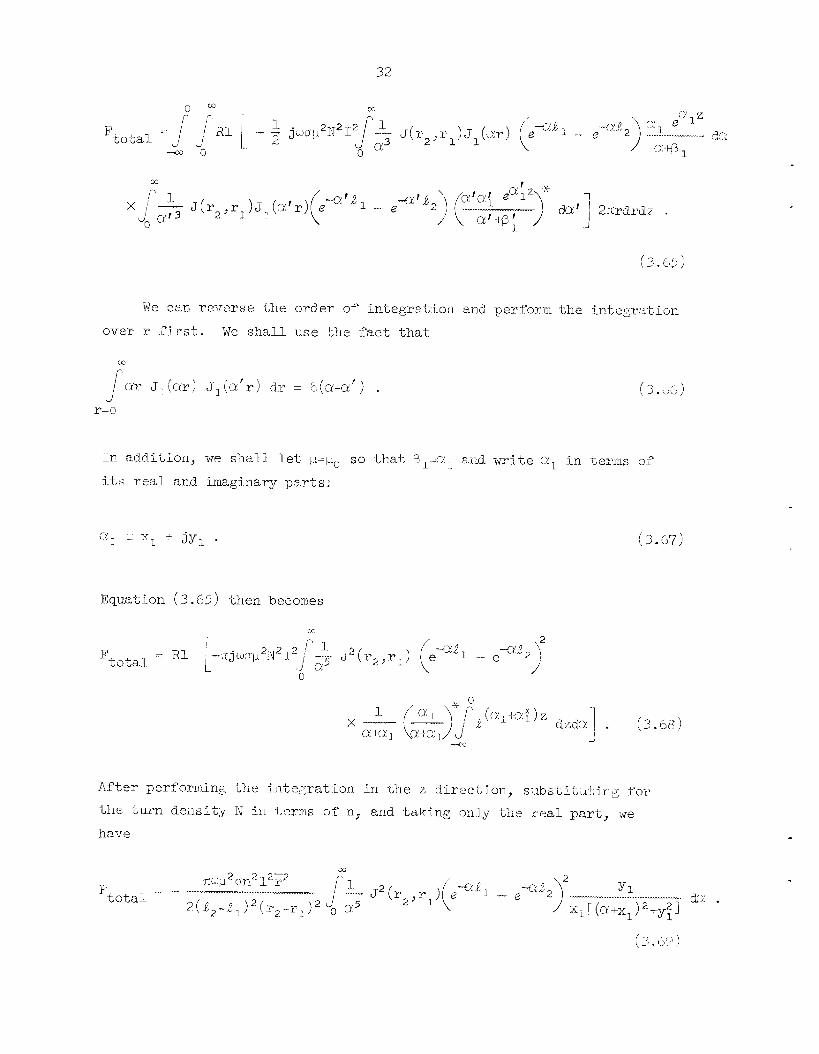
32
We c3,n re-verse the order of integrat . ion and peyforrn the integr,%tion
o v w 1.- fimt. We sha l l use Lhs fac t that
al- J,(c*r! J- , (c r I \ r ) d.i- = r 9\a-ufj I . r r-o
( 3 . 4
CX- x1 + jy, .
Equa,.tion (3.65) then becomes
(3 .67)

33
This i s the ne t eddy-current force produced on the cor?duetor. A computer program (FORCES) designed t o e a l e - d a t e t h i s force i s given by
ixqui re e t ax. 2 o -- B. Reflect ion Coil above a Two-Conductor Plane
A r e f l e c t i o n c o i l , as sliown i n Fig. 6, i s usually used i n t'ne phase-
sens i t i ve eddy-current instrument. 21j 2 2 This configurat ion i s actually 8 combination of spec ia l cases of' t h e s ing le c o i l above a two-conductor
plane.
1. Voltage and Phase of a Reflection-Type C o i l
We s h a l l ob ta in t h e d i f fe rence between the vol tages induced i n the two small pickup c o i l s by a current i n t h e l a rge driver c o i l .
up c o i l s a r e connected i n opposit ion so tha t , i n air , the voltage c i i - f -
ference vanishes. However, when t'ne c o i l s are placed r1ea.r a metal.,
t he re e x i s t s a vol tage d i f fe rence caused by- a "reflected wave" coming
back f r o m the metal.
The pick-
The ne t vol tage induced i n t h e pickup co i l s Is
v = v - pu2 vpu, ' ( 3 . '70 )
where t h e first pickup i s nearer t h e m e t a l than the second pickup.
According t o Eq. (2.11) the voltage i n terms of t h e vector potenti-al 5.s
Due t o t h e symmetry of t h e pickup c o i l s , J , - J , is equal to ,t,-e,,
and t h e c o i l s are recessed an equal d i s tance from khe ends of t h e d r ive r .
*IC. V. Dodd, Mater. Evaluation -- - 22(6), 26C-263 (1964).
2 2 C . V. Dodd, Mater. Evaluation __ 2 6 ( 3 ) , 33-36 (1968).

ORNL- D12'5 68-7312

Subs t i tu t ing t h e vector p o t e n t i a l f'rom Eq. (3 .48) i n t o (3.71), per- forming t h e in tegra t ion o-rrer r and z , and normalizing the dimensions gives
We can make the following d.efinitions:
LZ = length of the driver coil.,
Lt, = length of t h e pickup coi l ,
L5 ::: distance t h e pickup coils are recessed, L = spacing between &river coil and metal o r "lift-off."
Subs t i tu t ing these into Eq. (3 (1 7 2 ) yields
(3 .73 )
A. computer. program (RF'XT) designed -to eal.cdate .LIE phase and anrplitude
of this vo l t age may t;e found i n the I - i t e r a t w e a Z 3
335 . W. Thquire, C. V. Dodd, W. E. Deeds, and PJ. G. S p o e ~ i , Computer Progrms f o r Some Eddy Current Problems, OKNL-'T'M-2501 ( i n p r e p a r m

36
O R N L - D W 3 68-10310
( M A X I M U M L;FT Z E R O LIFTOFF)
. . . . . . . . . . ut
V, - A sin (Q,. 1 Si! . (3.76) i

37
To determine the phase s h i f t f rom @1 due t o a change i n l i f t - o f f ,
thickness 01" conductivity, we subtract Q from @I t o get i
(3 .77)
Luquire _I- e t a1.23 give a program (DISC) designed to ca lcu la te t h i s phase
s h i f t . Jk addi t ion they give anot'ner program (RFLCYC) clesigned t o csl- cula te the phase s h i f t fo r an incremental thickness change. It f i r s t
ca lcu la tes t'ne ptiase and amplitude of t h e voltage a t zero and rmximum
lift;-off' for t h e nominal. thickness value, s e t s the discriminator t o
t r i gge r a t the proper voltage VI, and then ca lcu la tes t he phase s h i f t
f o r small var ia t ions TYom the nominal thickness. The program w i l l
perform these calculat ions for a number o f d i f f e r e n t values of r2hyrj.
3. Defects i n the Cladding Material.
We can wr i te the equation f o r the voltage induced i n the pickup
c o i l s by the presence of a current defect when a current , I, is fl-owing
i n the dr iver coil. simply by subs t i t u t ing the vector po ten t i a l for
region I11 i n Eq. (2.28) t o obtain
we sha1.l now n o r m l i z e t ~ i e dimemions i n E q . (3 .78) anc~ again write the equation i n terms of the dimensions of t he dr iver c o i l , the pickup
c o i l , t h e pickup eo51 recess, and the I i f i - o f f :

38
4 - Defects in the Base Ivlatei-ial- - .......___I - ..............

39
A program (WDFTB) presented elsewhere23 i s designed to ca lcu la t e
t h e d-cfect s e n s i t i v i t y f a c t o r f o r a s rnn l l curl-ent rlefect i n t h e base
mater ia l .
C . Through TrmismLssion
A through-transmission c o i l arrangement i s sho~m 2.n FLg. 3 . I-Iere
we have a s igna l , t ransmit ted by a l a rge driTrer c o i l through a metal
p l a t e , received by a pickup c o i l .
r e f l e c t i o n case except t h a t t h e pickup c o i l i s now Zccated i_n region IV, This case i s i 2 l m O S t identical . t o t h e
1. Voltage and Phase of a Through-Transmissinn Coil
We s h a l l obtain the phase and amplitiide of t h e voltage induced i n
Subsbitutisng t h e plickup c o i l by a current J“lowing i n the dr ive r c o i l .
the vector p o t e n t i a l i n region lYJ as gjven by Eq. (3 .4 ’7 ) ) with ri :::O i n t o ~ q . (2 .11) gives
2
where 4 and T ( 4 ’ and TI’) are the l i f i - o f f and length of thc dr ive r
(p i ck lq ) c o i l , respec t ive ly . performing t‘ne in t eg ra t ion yie~ci:;
We have presented elsewhere23 a computer p r o g r m (WnU5) designed
-to calmlate t h e phase and amplitude of t he vol tage for a. throu,@-
transmission co i l .
I I

40
CRNL-DWG 68-7313
Y
Pig. a . A 'l'l?rcJugh-Transm-j_ssion Coil. Amangement .
2. Defects in a P la t e -
\.le can eastly w-?'.te Llie equation for the voltage in t h e picklip
coil. j-nd-ixed by Liie lpresence of n cul-rent defect when a current flows
i.r-l t'ne driver coil- This i.s t h e same as the reffj.eckion case, except
that now the pickup coil is on the oppos i te s i d e of the metal. The
vector potenkia.1- produced at the defec t by a unit current fl.ow-i-og i.n
the pickup is si.ven by the same expression. as t ha t for the dr iver ,

4 I
except t h a t the dis tance of t h e defec t beneath t'ne metal now i s set
equal t o c - z . If we norrr;tlize the dimensions by r and let, r2=O, we
h w e
which we d iv ide by I, Wol
i n the work of' Luquire -- e t a lS2 ' there i s a p r o g r m (THRUDF) designed to
ca lcu la t e 1;h.e defec t s e r i s i t i v i ty factor f o r .f;'his case.
tm obtain the defect sensktiv'i-Ly factor.
D. Coil between 13x0 Conducting P la t e s I
This configurat ion i s used f ~ r spacing ineasxmments,2" and i s shown
in Fig. 9.
1. General Derivation
'The differeri$ial equation for. this case is Eq. ( 2 . 1 j l and t h e general solution i s given i n Eq. (3 . Uj) . equations f o r the vector p o t e n t i a l i n each regioxl we obtain
I-Iowever, when we wr i t e the
(3.84)
2'T. V. Dodd and R. W. McClwig, Fuel Element Coolaat Channel and Other Spacing Measurements by Eddy-Current Techniques, ORTJL-TM-129 ( 196%) .

42
k ’ i z . 3. A D c l t s r’niction Coil between Two Condocti ag Plates.
( 3 . 8 5 )
and
(3.86)
(3.sri)
( 3 . 8 8 )

L* 3
(3.89)
(3.91)
z= e z=e
( 3 .93 )
W e can s u b s t i t u t e Eqs . (3.84) through (3.87) i n t o Eqs. (3.88) m
through (3 .931, multiply by d J,(a'r) rdry reverse the order of
integra,tion, and use the Fourier-Bessel i n t e g r a l t o s impl im them.
then get
We
P 2 C, - B, = - C 4 . a
(3 * 94.)
(3.95)
(3.96)
(3.97)
(3.913)
(3.99)

We have s ix equations and six unki?owlls. If we soJ.ve for each constant and subs t i t u t e the resii.l.ts into Eqs . (3.8)+) t h r o ~ h (3 .87)
we g e t for the vector potential i n each region
m
M
and.
J
da J
1 I da.
(3.1.02)
( 3.103 )
We now have Yne equa'iions f o r the vector pote?'i,ia,? due -to t h e
currcerrt in a de l t a flrrrction co?.l- 'nelmeen two conductiilg planes.
use Eq. (2.5) t o superirqmse the vectoi- poten$ial-.s of delta function coil-s t o f ind . t h e vector yoteiitial. produced by a c o i l of rectanglular
cross secti.or? as shown i n Fig . 10. Si_n.c-e we a:m concei-iiec? only with
the Tegion cont&ii.:cig the c o i l , region T I - i l I T ? we have
We can.

45
O W L - D W G 68-7344
Fig. 10. A Coil of Rectangular Cross Sect ion between Tsio Conducting Plates.
Carrying out this integration yields

46
This i s t h e e q m t i o n fo r the vectijr potential- of a c o i l with rectangular
cross sec t ion in region T I - T I T .
2. Impedance of a Coil between Two Conducting ?late5 .......... .... .-.
To ca lcu la te the c o i l impedance, we subs-kitute the equation for
tile vector po ten t i a l i n region 1 1 - 1 ~ i n i x ~ g . (2.1.8) and iiltegi-ate
over -Yne dlmens~ons of t'ne c o i l . In addt t ion , we normalize the d i m e n -
$ ions i.i? terms o f %. We then have I
where f(a) i s deflmec! by
'i"nis bpedance may be normalized- by dividi-ng by t h e magnitude of the a i r
impedance, given i n Eq. (3 .55) .
cu la t e the iiormalized impedance f o r this case i.s gi.ven by Luquire et
A computer prograx. (Fill'NCO) riesi.gned t o cal-
-- ........... ..--
25J-. W. L i q u k r e , C . V. Uodd, W. E . Deeds, and W. G . Spoerri, Computer Progi-ams f o r Some Eddy Curi-eilt -_ Problem, ON\.L-TM-2501 ( i n p : r e p ~ ~ r i w

E. Coi l Encircl ing a Two-Conductor Rod
We s h a l l assume a d e l t a f'unction c o t 1 encixcling an i n f i n i t e l y
long, two-conductor rod, as shown i n Fig. 11.
1.. General Derivation
The general d i f f e r e n t i a l eyuaticn i s t'ne same as Eq. (3.3) f o r a
c o i l above a conducting plane.
term, we have
If we neglect t h e displacement current
(3.108)
Now, however, we s h a l l assume the seyarat ion constant t o be negative:
1 S Z ( 2 ) ,, = constant" = - c i2 .
z ( z ) az2
Then
z ( z ) F sim( ) + G cosrx( z-zo )
and Eq. (3.108) becomes
( 3.109 )
(3.110)
(3.111)
The solutj-on t o Eq. (3.111) i n terms of modified Bessel functions
i s
We can now wr i t e t h e vector p o t e n t i a l i n each region. We s h a l l
use the f a c t t h a t it i s synmetric (with respect t o z-z,) t o e l iminate
t h e s ine t e r m s and t h e f a c t t h a t KI (0 ) and Il(a) both diverge t o

0 RN L-- DW G 6 7.- 25 24
I 111
I I
.-i Fig. 11. Delta Function Coil Encircli.ng a Two-Conductor Rod.
IV

w e have
The boundary condi.tions between the d i f f e r e n t regions %re
( 3 .I13 )
( 3.114)
( 3 - 115 )
( 3.116 )
(3.117)
( 3.11G
(3.119)
(3.120)
( 3 . Y21)
( 3 -122 )

50
11’ we niulti.p3.y botil sides of Eq. (3.1.1.7) by cosa’ ( z - , z o ) and
i-ntegi-ak from zero t o infinity, we obtain
We can reverse t h e order of in tegra t ion and use the oi-t‘nogonal.-i.’iy
pl-o-perties of the cosine in.tegral o r use !;lie Fourier i n t e g r a l theorem
Thus, we can solve tile ii1tegra.l. Eqs . ( 3 . IJ-7) through (3.1.22) ~ We sbal.1.
uf: a . t o designate (a2 + jqm. 1‘ and ,R
use primes t o designate deri.u-s.tives w i t h respect t o t h e a.rgulilent. get fYom -the i n t e g r a l Eqs . (3.13.7) t‘nrough (3.122)
1 - t o designate ”0 a . . We sha l l
1. 1. i cli 1 We

51
We now have six equations with six unknown constants. equa"cons may be solved to give the constants.
following definitions:
The W e s h a l l make the
and
The constants can then be written as
P-p , (ar, 1 c, =
ablsD (c~) 7 (3.133)
(3.134)
(3.135)
(3.130)
(3.13'7)
( 3 I 138 )

52
Me can now write f o r t h e vector potenti-al. i-n each region
( 3.139 )
'These are the equations f o r a del ta fumction coil encircl ing a two- con&.i.cltor rod. We sha l l now superimpose these sohlt5on.s t o form a c o i l
with rectangular cross sect ion as shobm i n Fig. 12. Tnis i-nvolves sub..
s.Lil;uting Eqs . (3.139) t'nrough (3.142) into Eq. (2.5) and pwforrning
Lhe i n t e p a t i o n over the dimensions of the coil..
defj-nit ions :
L We make {;he folI.ovin,g
(3.1.43)
and. similarly

53
ORNL-DWG 67.- 2525R
r---- b ---+ ' I I r l ---A I I
'2 ------ ___..._I__
Fig. 12. A Coil of Rectangular Cross Section Encircling a Two- Conductor Rod.
We then g e t for the vector potential produced in the different
regions by a coil of rectangular cross section

(3.147)
(3.743)
Ti?. t'ne reg ion of the c o i l , between reg ions TIL and IV, we have
(3.149)
or

55
It i s t h e o r e t i c a l l y poss ib l e t o evaluate A ('' ' ) and i t s i n t e g r a l s
over r and z. However, the fn t eg ra l s
would require a very d i f f i c u l t numerical evaluation, and it i s possible
t o obtain these i n terms o f a previously defined function. have shown that,
Eason e t d..z6
We in ins t have z-zg > 0 and rO > r i n t h e rtbove equation if it i s t o remttin finite. To do t h i s we break t h e so lu t ion i n t o two regions, using t h e
ones t h a t remain f i n i t e i n t he i r respec t ive regions. We then m u l t i p l y by rodrodzo and in t eg ra t e over the cross sec t ion o f the coil. We get
By using "ihlis result i n Eq. (3.l.50) we can w r i t e
Thus, we have obtained Y'ne vector potent ia l . for a c o i l of rectangular
cross section i.n te.rrrs of an integral . of somewhat simpler fimc'cions.

56
2. Impedance ol” a Coil Encri-rcling a Two-Condi~-cl;or Rod ..._lll__ .-II_ 1 1 1 _ ~ l_l^
To calcul.a,te t h e c o i l rimpedance, we subs t i t u t e t h e equation f o r t‘ne
vector potentia?.. a t the coi.l., A(3’4)(r,z) i n to Eq. (2.1.8) and p e r f o m
t h e integratj-on over t he dimensions of the coil;
Nomml.i.zali.on with respect t o r gives
A compixter pl-.ogram (ENCCOS ) performs this r a the r d i f f i c u l t j_ni.,egration. 2 7
3. Defect:; i n the Outer Material. 1- .... -__ll_-__l_.
We car. m i t e the eqimtion for the impedance change d.ue to a cur ren t
defect in regri.on IT b y puttjng t h e vector potentisl f o r iOef;_ ‘-1 on 11 i i2ko
Eq. (2 .28) . the a i s irrped.ance, then
If we normalize the dimenstoris by F and the impedance by
27J. W. Luquh-e, C. V. Dod.d., W. E. Deeds, and W. G. Spoeri , Computer ORPTL-TM-2501 ( i n p y q j a r a t i . o i i r - -
__I..
Z’rograms f o r Some __II_ E d d y Current Problemc; _____l_l_ _._^_ 2 - 9

57
from which we e a s i l y obta in the defect sensitivity factor since
( 3.157)
Luqui.re e t al. 27 give a program (LDllFT5) designed t o calcula-Le the defect s e n s i t i v i t y f a c t o r due to a s i n g l e defect i n t he outer c.onductor.
the Same work is a program (ENDFTL) designed to calculate the d.efect
s e n s i t i v i t y f a c t o r f o r a defect I.ocnted at successive poirrtls of' a LzLtice
of posi . t ions in the outer conductor.
In
4. Defects i n t h e br ier Plateris1
bubstitutiotl of Ey. (3.145) i n t o Fq. (2.28) y ie lds the aonna1ized
irrrpedance chmge due t~ a defect in region 1:
A p r o a r m (ENDFBS) designed to calculate the rlei"f2c-b s e n s i t i v i t y Factor f o r
Yn i s case is also given by Luquire -- e t al. 2 7

58
5 . Dtfferentia,l. Coil Svstem
A differentia!. c o i l system, as shorn i n Fig. 13, is f requent ly used
YnTs c o i l arrangemexlt i s us& both with t'ne i n the inspect ion of tubes.
coils enc i r c l ing a rod or t i he and with the c o i l s positi.oned in s ide a
tube.
i r r Fig. 14. driven by c u r r m t s 1,- and I,.
The coi1.s a m usual ly CoiTflected. i.n a br idge arrangement, as shorn
We s h a l l assume tha-t; the twc, cor i .1~ are iden- t ica l and are
The t o k l . . vol tage induced -in c o i l 1. i.s
Where
Z,, is t h e self-impedamce i n the presence OS metal but not t h e ck-fect, M,, i s the mutual coupli.ng between the two coil.s, ZId is the defect iinpedaiice diie 'io a current i n c o i l I.,
M l z d i s t h e rflutiial. coupling between c0l.l.s 1. and 2 due t o t he flaw.
& o r current defects atid spbt:rical. magnetic defects, we have
\$e also have a s imi l a r equation for v,( t o t a l ) :
( 3 " 1.62)

59
ORNL- DWG 6 7 - 2525R2
I S
tern.

60
O A N L - D W G BR -10308
~ ...... ~ . .
I
COZlPENSAl RES1 STOI
Fig. ll+. A Bridge An-angement Used with Differen t ia l Cotls.
NOW MI, = M,, and = M2,d i n general, and, s ince we clefi.ned tine two coils to be ident ica l , Zll -: z22. Therefore, the voltage d.ifPere11ce is
The circif i t 3.s generally operated near null, so t'ria.1; 11-12 i s very small. Slnce i.s also small, this term can usually be neglected.
The voltage difference due to a defec'i then becomes
Now if we take 6 as .tile cente:r-to-center :;pacine; between. the c o i l s ,
we have
Fwt'nermore, i.f we have only current defects FTP can w r i t e f o r the
voltage difference

az2 Vol I, . (3.166)
The term i n the braces can be ca l l ed t h e d i f f e r e n t i a l defect sensi-
t i v i t y f a c t o r and i s obtained by subtracttrig one defec t s e n s i t i v i t y
f a c t o r from t h e o ther .
designed to ca lcu la t e t h e d i f f e r e n t i a l defec t s e n s i t i v i t y f ac to r for a
defec t a t po in t s on a l a t t i c e from a l a t t i c e of values of the defec t
s e n s i t i v i t y f ac to r .
W e have presented elsewhere27 a program (REf lDIN)
F. Coi l i n s ide a Two-Conductor Tube
A d e l t a funct ion c o i l i n s ide a two-conductor tube i s shown i n
Fig. 15.
1. General Derivation
W e can start w i t h t h e same general equation, Eq. (3.3.12), i n term of modified Bessel funct ions that we used f o r a c o i l enc i rc l ing a two- conductor tube and w r i t e t h e vector p o t e n t i a l i n each region.
can drop the s ine t e r m and Ylze coe f f i c i en t s of K 3 ( o ) and I1(w).
then have f o r t h e vec tor p o t e n t i a l i n each region
Again, we
We
(3.167)
( 3.1.68)
(3.1.69)
(3.170)
The boundary conditions f o r a delta funct ion c o i l a t ( r o , z c ) are

62
Fig” 15. A Delta Function Coil inside a Two-Conductor Tube.
-
r-a r-=a
(3.1.73)
( 3 . l r l L + )
( 3 . 1-75 )

63
We shall f i rs t s u b s t i t u t e Eqs. (3.167) through co Eqs. (3.1.70) i n t o
these s i x eqilations, again milltiply both sides by [ casu'( z - z o ) d( z-zo),
reverse t h e order of in tegra t ion , and use the orthogonality properties of t h e cosine in t eg ra l .
1
We then obta in
We naw have s ix equations with six ~mErulovn constants. We shall mke
t h e following d.efinit ions:

( 3.186 )
(3.187)
(3.188)
(3.189)
(3.190)
W= shal l now substitute these constants i n t o thej r rpapectivc equations to obta in the vector potential i n each region due to a del%&
functioii coil.:

65
( 3.194)
Trrese izre the equations fox a delta funct ion coil i.nside a Lwo-
conductor tube. We shall now superimpose them to cbta in the results f o r
a c o i l of rectangular cross sect ion, as shown i n Fig. 1.6. We do t h i s by
subs t i t u t ing Fqs. (3.191) through Eqs . (3-1-94) i n t o Eq. (2 .5) and i n t eg ra t ing over the dimensions of’ the c o i l . We get f o r the vector poten-
t i a l in the different, regions
and

66
Fig. 16. A Coil of Kectangular Cros Tube.
In the regj-on of the coil., between regions I and TI, we have

We have now obtained t h e vector p o t e n t i a l i n each region.
2. &medance of a Co i l i n s ide a 'Two-Conductor Tube
To ca l cu la t e t h e c o i l impedance, we s u b s t i t u t e the equation f o r t h e
vector p o t e n t i a l i n region 1-11 i n t o Eq. (2.18) and i n t e g r a t e .
normalizing the dimensions w i t h respect t o the mean ( fo i l radius we get
After
A computer program (I?srJCOS) has been desi.gned t o ca l cu la t e t he norm1i.zed.
imped-ance f o r t h i s case.28
3. Defects i n t h e Inner Material
We can w r i t e t h e equation f o r t n e impedance change due t o a, current,
defect i n region 111 by subs t i t u t ing the vector p o t e n t i a l i n regton III
i n t o Eq. ( 2 . 2 8 ) . If we normalize t h e dimensions by I- and - the impedance by t h e a i r value, we ob ta in
-
"J. W. Luquire, C . V. Dodd, W. E. k e d s , and W, G. Spoeri, Corpnter Program f o r Some Eddy Current ProbLems, 0?3C\JL-TM-2501 ( i n prepara t ion) .

68
l2 J x [sina(z-&,) s i n ~ ( z - ~ , ) I d.a
from which w e can r e a d i l y f i n d t h e defect s e m i - t i v i t y fac tor , s ince t h i s
i s j u s t VOI., n There i s a prograrfl (TIVDFTS) desigried -to cal.cii~late t h e defecl; sensi-
t i v i t y f a c t o r due t o a small c i r ~ e - : i . t defec t i n t h e inner conductoy.28
i n addi-tion, t he re i s 8 prograin (INDFTL) designed t o calcil.l-ate t‘ne defec t
sensii ; ivi . ty factor at al.1 poi.nts i n a l a t t i c e i n t h e h n e r conductor.
4 . Def’ects i.n the Outer Material. ~ .I...
Subst i tut ion of Eq. (3.1.98) i n t o Flq. (2 .28) gives the no-maltzed
impedance chairge clue t o a defec t i n reg:ion ZV:
‘lhere i s a program ( i N U m 5 ) designed t o ca l cu la t e the defec t sensi- t i v i t y Pac Lor for’ a cuwent defect i n Liie o u t ~ r condiictor . 2 8
I V . Calculated H < ? s u l t s f o r Some Important Applicati .ons ................... 111111
WP have derived Lhe equalions for some physical propert ies f o r t h e
W e six riifSerent, coi 1 and conrjuctol- configurations show i a F L ~ . 17. shall now present computer evaluaiions O F some of t hese properli-es,

69
ORNL-DWG 68-7311
(01 CASE 1: COIL ABOVE TW-CONDUCTOR PLANE.
I C ) CAS€ 3: -1HROUGH-TSANSMISSION COiLS ( A S USED IN PHASE-SENSITIVE INSTRUMENT.
(b l CASE 2: REFILECTION-TYPE COIL ( A S USED IN PHASE-SENSITIVE INSTRUMENT I AEOJE A TWO-CONDUCTOR PLANE.
(dl CASE 4: COiL BElWEEN TWO-CONOUCIING PLANES IFOR SPACING MEASUREMENTS.
le1 CASE 5: COIL ENURCLlNG TWO CONDUCTOR ROO.
( f l CASE 6: COiL I N S I M TWO CMIDUCTOR TUBE.
Fig. 17. Eddy- Curreiit Problems Treated Here.

70
The first quznt i ty j.s the iiiiped.ance of a c o i l above a two-conductor
plane.
ness i s var ied froin zero t o iiifini-Ly. There are two d i f f e ren t curves
corresponding t o two differeint base nna-Lerials of different, conduct ivi t ies .
These curves i-ndicate t'ne accuracy of measuring chdd ing thickness and
the e f fec t of a change i n conductivity of -tine base matei"ial.
Figure 18 shows how the impedance vari.es as t h e eI.addi.ng thick-
0 73
0 72
0 71
0 70
F z ? 069
5 0
B
0 5 5 W
k 0
rY
- >
2 067
0 66
0 65
0 64
0 63
ORNl - DPG 67- E5 ........
I - - - - - - - - - I
v =CONDUCTIVITY C =CL.nODING THICKNESS/i
-0.0476 ILIFT OFF J,= ~F I I I
U
009 010 O t 1 012 Oi3 044 0.15 O f 6 RESISTIVE COMPONENT
P ' i t ; . 18. Irnpzdancr of a Coil above a TkTo-Conductor Planp.
A s a fu r the r ayp1-7 catton, we have calculated t h e defect s e n s i t i v i t y
factor for a c o i l above a conducting plate. We have calculated the frzctoi- a t poin-Ls -in a l a t t i c e and p lo t t ed contours of constant defect s e n s i t i v i t y .
Figure 19 shows Line defect sens i - t iv i ty factor contours superimposed on a
sca l e drawing of t h e c o i l and conductor. We can w e these contours t o
ca lcu la te the fmpedance change due Lo e, cui-rent defect a t any loca t i~on
i n the m e t a l . 01- due t o movement of t h e deyect pas t the coi-I.. The
normalized impedance change 7.s t he product of t he defect s e n s i t i v i t y
facbor, t he volume of the defeci;, anti the shape and. o r ien ta t ion fac tor .

r-! D
X

'7 2
-
Another appl icat ion involves t h e ref]-ec Lion- type c o i l . We a r e attenptimg to determine tlie optimum operating conditions for inaximurn
s e n s i t i v i t y to an incremmta!. tiiickmss change from a ce r t a in nomilial
thliclulegs.
var ies as a finctTon of tlie operating conditions f o r four d i f f e ren t
nominal 'ihicknesses . Froni this graph, one can- choose t h e irptlirrwn f re-
quency for a ps.r..ticulaii c o i l , m-Lerhl. ~ and thickness range.
Figiinie 20 shows how the phase shift per jncremental t,hrichess
(0- ANGULAR T:iCQUENCY /I- PERMEABll I I Y
0.0 1 0.1 1 10 100 io00 T 2 w p o -
Fig. 20. The Phase Sh.ri.P.L f o r i l O % Thickness Vai-iatioii f r o r ~ ~ Nomi.na1 Thi.ckncss.
For a co i l encircl ing a two-conductor rod, Fig. 2 1 shows t h e
normalized impedance a x a functi-on of the radFus of .l;b= inner (:onductor.
The conductivi.ty of t'ne inner conductor differs for Yne -Lwo cwves, but
a1.l other pa.srameters are the S ~ E - Thri.s ex3nipl.e demonstrates the range snd s e n s i t i v i t y of c l a d t h i r_kj?css nieasurements arid the prob1.em.s r c su l t i rg
from a change i n the coiiduc::;ivity o f the inner conductas ~

7 3
ORNL-DNG 58-7318
c
0.64
0.6?
0.60
t 1 0 5 5
2 :: L 0 5 6
W -2 -
a W
0 54
0.5:
0 50 0 7 0.8 0 9 i.0 I 4 1 2 4.3 4 . 1 1 5 1.8
RESISTIVE COMPONENT
Fig. 21. Impedance Variation a s a Function of Inner Radius.
V. Experimental Ver i f ica t ion
While we do not yet; have experimental measimements f o r every case
derived., we do have r e s u l t s for einough cases tu verify the general tech-
niques. It is very d i f f i c u l t t o c o n t ~ o l the c o i l dimensions prec ise ly
enough t o obtain good agreement between calcul.atec1 and. measiired msults. Qlr fi.rst experimental measurements are of t he indiuetance of a coi.1
in air . They are compared with ca lcu la ted values in Table 1.
The rneasiu?ements were made on a bridge w i . t h a reported accziracy of
+0.2'$.
c o i l wind.ings.
W e f e e l that m o s t of t h e ermr i s due to small va r i a t ious i.n the
We have constructed a fLmily of f o u r coils of d i f f e r e n t sizes. but
with %he same r e l a t i v e dimensions.
c o i l at six d i f f e r e n t frequencies and a t four d i f f e r e n t spacings above We rneaswred the impedance of each

74
Table 1. CalculaLed a n d Measured C o i l ind-uctance
I - ............ Coil Heas IJY e d. Calculated Error
NUlIlber (d ( r r t ) ( %I ...............- 1 _ 1 ^_ __- 1 11.38 11.1688 1.8 2 14-595 1.Lk.3438 1-72
3 134.17 135.216 0.38
4 3.157 3.16425 0.23 . 1111 _I_
a large, thick al.urni.num p l a t e .
i n E’5.g. 22.
t he four different coils.
la.t;ed valiies i s excel lent i n ’ihe regions o f the p l o t repi-esenting the
The r e s u l t s weye normalized and p l o t t e d
Each cxperirnental. pOri.iIt represents the average of values for
The agreement b?i;-ween experimental and calcu-
0 5 t
I 0 0476 ‘ 4 2 9 8
L ..... e.- C4LCULATED ”, V4LUCS
a EXPERIMENTAL VALUES
~ ?=MEAN COIL RADIUS i w!l or ‘=CONSTANT
1, = LIFT -OFF/?
0 0 05 01 0 15 0 1 RESISTIVE COMPONENT
b’ j g . 22. Varia L i o n OF Expcrirtien tal and Calcul a,t,nd Values of Normal i zed C o i l hpedance with Frequency 2nd Lift-Off.

75
higher frequencies.
ments are relatively inaccurate.
experimental error in all cases.
At the lower frequencies, the experimental measure- The agreement is within the limits of
We have obtained some experimental results for a reflection coil
We measured the amplitude and phase of’ the above a conducting plate.
voltage in the pickup coil as a function of lift-off‘ and plate thickness.
Figure 23 compares the measured voltage with the calculated voltage, and
Fig* 24 shows the measured and calculated phase shifts. In addition, for
the through-transmission case, we measwed the phase and amplitude of the
voltage of the receiver coil as a function of lift-off and metal thickness.
I 2.4 -
2.2 -
2 .o
1 . 8 ,
-V- CALCULATED VALUES 0 EXPERIMFNTAI- VALUES
P2wpm- .1 i311 F= FREQUENCY T=CURRENT IN DRIVER COIL N=NO TURNS IN DRIVER COIL N ’ Z N O TURNS IN PICK-IJP COIL P=MEAN COIL HADIUS=O 2825 In <“=ANGULAR FRE OUENCY p -PERMkABIL ITY
0.92 O.Y4 0.96 0.95 4.00 1.02 1.04 1.06 THICKNESS/ i
Fig. 23. Vartation of Experimental and Ca.1culated Values of the Magnitude of the Reflected Voltage with Thich-ess and L i Y t - O f f .

- r - ” - ?=MEAN COIL RADIUS-0 2825 i n “=ANGULAR FREQUENCY p =DE R M EA6 I L l TY v=CONDUCTIVITY f=THICKNESS/ i
Fig . 24. Variation of Experimental a n d Calcsulated Values of’ t he Phase S h i f t of t h e Reflected Voltage with Thickness and L i f L - O f f .
Fiyi i re 25 shows how the magnitude of t h e measured voltage compares wi-th
the calculated values, and Fig . 26 shows the measured and calculal:,ed
phase sh i f t s . The agreement i s fa-irly good and within the limits of
experimental e r ra r .
We have measured and calculated the eddy-current force exerted on
a large, t h i c k aluminum p l a t e by an a l t e rna t ing current flowi.izg i n a coil..
The force was measined for two coils of d i f f e ren t s i zes but .the same
r e l a t i v e d.imenaions. It was then di-vided by the squa,re of the number of
ampere-turns and mult ipl ied by lo7.
Table 2.
The averaged resu l t s are given i n

'77
ORNL-DWG 68-9862
~
'.oo ~ -CdLCUL.ATED VALUES EXPERIMENTAL VALUES r = THICKNESS/? F= FR EQ U E tCY
N=NO. TURNS IN DRIVER COIL N'=NO. TIJHNS iN PICK-UP COIL P=MEAN COIL RCOIUS w=ANGULAR FREQUENCY u-PERMEABILITY LT =CONDUCTIVITY
0.98 . I=CURRENT IN DRIVER COIL
........... ~~ .....
o , ~
0.94 i z w p 0 = 5 . 5 3 7 2 i~ ...... L-. ~ ............ !.-- 0.4 0.5 0.6 (
THICKNESS/? 7
Pig. 2 5 . Variation of Experimental and Calculated Values of the Magnttude of the Transmitted Voltage w i t h T2iiehess and Lift-Off .
ORNL-OWG 68-9860
I
_ - -
f = THICKNESS/?
_ - - 0 5 06 0 7
- 0 2 8 0 4
THICKNESS/i
Fig . 26. Experimental and Calculated Values of the Phase Stni.ft of the Transmitted Voltage with Thickaess and Lift-Off.

78
Table 2. Calculated and. Messwed Force
..-. _l_l .._......_ _._. I- ._ -. . . . . _ _ ._.. . Measured. FoYce/r2 I2 Calculated Force Error ( X newton/amp2) ( X J.0-7 newtmn/amp*) (3.) r 2 pLlj0
3. 082 8.628 2,. 65 77.05
329.8 862.8
3 . 082 8.622
24.65 w.05 329. Z 802.8
1,053 2.6'63 4.834 7.148 9.326 10 e 54
1.l2146 2.80859 5.11168 ' i .52462 9.82756
10.7935
I,i.ft- Off,& = 0.0952 0.9414 2.316 4.149 5.988 7.692 8.575
0.987604 2.41421 4.29660 6.1.7 143. 7 . 8 5 3'1 8 8.53364
6 . 1 5 .0 5.4 5.0 2 . i 2 . 3
.+.7 4 . I 3.6 3.0 2 .1 -0.5
~ .___II
VT. Acciir-acv of Calculations
This technicyip, l i k e most otheiis u s e d i n engineering, i s "exart;
except f o r a f 2 w assuqtions we have io make i n ord~r t o work the probleril."
We w i l l now disciiss t h c probable erpors i n some of these assurflptjons.
A. Axial Symmetry 1-11 -_1--._..--
This i s a very good assmp.tion, but we cannot easily wind c o i l s tha:t
This e r r o r will vary w i t h tile winding tech- have p e r f e c t axial symmetry.
n-ique and w i l l decresse as I;he number of turns on t h e coi.1 and tile co i l -
Lo-conduc-tor spacing increases. This e r r o r wiI.1. be e f f ec t ive ly rwh~cecl
when nornElized inipedance ris calculaLed.
less than 0.01-%.
L
For a typical coil it should be
B. Current Sheet Auproximtion
'I'his error arises because we have assumed a. cu r ren t sheet , w i l i J e we
act1ia3.l.y h a w a coi 1 wound bcith round, insulatPd wire. Some correct ion

formulas are given by Rosa and Gi-overZ9 for the inductance of' a coil i.n air I
From Eq. ( 9 3 ) by Rosa and Grover we have
.m] . The s;ymbols D and d are the wire di .meters w-itki end wj-thout ins~Lliztion, respect ively. This cor rec t ion i s pos i t i ve and i s usua1.l.y a small frac-
t i o n or" t h e t o t a l inductance. TJsing the approxim&te Eg. ( 8 ' 7 ) f r o m Rosa and. Grover f o r the inductance we can wi.te f o r %he frzctfonal inductance
change
(6.2)
where a11 dimensions are norm3lized by -the mean coi.1 radius. For a
typical coil writh 3-00 t u r n s , .tile change in i ndmhr ice i s G,l9$. In
pracf;ic:e most, c o i l s are not wound i n precise I-ayei-s of wrire as assumed
by Rosa and Grcwer, Instead, t h e windings are randomly p i l e d on. each
other u n t i l a C { ~ L I form i s f i l l e d . T?i?s effect should be a very sho.rl;-
range one., It wl.11 'nave a nri~c'il s~a l - le r eff'ec-t on some ot'ner pheaomena,
such 8,s normalized coil. imped.ance, w h i c h ilepend on t h e metal.
C. High r'requency Effects --
There ,are a number of' h igh Treqiiency c f f e c t s , and they are probably t h e most serioius sources of error i n t h i s ca lcu la t ion -technique.
1. The Skin Effect;
A s t h e frequency i.ncreases, {;he current densi ty ceases t o be imi-
i"cjrd.y distTPi.buted over t h e cross sec t ion of Yne w i r e but, bcevmes concen-
t r a t e d near the su.rface. T h e r e s i s t ance of the coil. increases, and the
i.nductaice ilecreases A s a first approxirrt8,tFon the resktance, R , of a c i rcu lar cross sect ion of' straight wire is'"
29Ee B. Rosa and 3'. W. Grover, Nat. B u r . Std. ( I J * S a I 9 Tech, Netrs ___ 31111. -- 8 ( I), 1-237 ( 1912) " -
Frederick W. Grover, Inductance Calculaticnns Working Forrnuhs a9d 30
'Fables, Dover, New York, 19W.

80
( 6 . 3 )
Browin and Sharp Ereqii~ncy ( h e r t z )
_g_-_ I I
Wire Gage ........ Nimber ._l___l. _____ ...........
20 G.C x 10' 30 67 x J03
4 0 680 x I O 3
r7 1.1 x 1c6
'Yhe self-inductance decreases sI.i.ghLly a t higher frequ.enc-ies du.;? t o
bhe concmtra t ioa of curr-eiit on t h e surface.
wi-:re, A , the self-inductance chailges fron
For a 1.eiigth of stm.ig1i.t
.E 2
as the frequency goes fi-om z e ~ o t o j t i f ' i r l iky, o r a ne t change of .... X X-' h.
Th3.s r e p ~ e s e n i s a ne t change of l e s s than 1.3 pplil oil a t y p i c a l c o i l . sk in e f f ec t f o r t'ne lease of a s brai,ghL wire i s mod.i.fi.ed. i.onsiderab1.y Wili . i l
t h e wire i s wound. i n t o a ~ 0 3 . 1 . .
or d er - of- mag it uii e e3 .t iilB t es .
The
IIowever, these equatrions m y be used f o r
2 . Interwi-nding ......... Capaci Lance
The interwinding capax i.t,a.ace i s -the d i s t r i b u t e d capaci-tance bets.r?en
t h e inrii.vi.d.ua! 'Lurns of wire, and it decreases as tile -t;hlickness of t'ne
wire insula-Lion i s increased.
acts much as a lurnped. capacitance i n para l - le l wi.th a sei-ies induc.iance and. resis.t;ame.
W'ni1.e it i s a d i s t r i b u t e d capaci tanoej it;
This prod.u.ces t h e resonant frequency
1 " . 3 = - .
rn ( 6 . 4 )

B 1
,4t frequencies much below t11e resonant i”requency ( [ A <: [ A i O J ) t h e res is tamce
arid inductance vary as follows: 3o
(6.6)
Near resonance, t h e reactance changes rapidly from mxximwn induct ive
reactance through zero t o maximum capacit7.ve reactance.
being capac i t ive ly coupled between t h e turns , tends t o flow across t h e
loops of wire rather than through them.
below - their resonant frequency. This e f f e c t also is short range and.
tends t o cancel oixt, in normalized ind.uctance ea.l.culations.
The cwrent ,
In general, c o i l s are used w e l l .
4. Displacement Current Effect,
In t h e a c t u % l crzleulation of the r e s u l t s , we have neglee1,etl %he ?is-
placement, curyen t; tgrrns # We made t h e following approximtion:
(6.8)

real. s.nd imaginary par ts of bhe irrrped.ance wa? +59 ppm and i11..3 ppm,
respectively. For the
coils am? conduc-iors norm3,1.1.y use& in ed.dy-cui~en'L work, t'ne eff ::et is
The err*or i n the c o i l i.ndiictar~ce was .--LAO ppm-
comp le-L e iy negl.-ig:i.l, 1.e .
We b.a.ve assumed that. t h e media a r e ].inear - t h a t i.s, B : pH and D - GE, whei-e 1-1 ana c a r e constants. This is a good assmpt ion i.f tile
1nateria1.s a r e nonfesrcma,gn.ztic o r i f al.3. [;he mgn.etic domaS.ns i n a fermi>-
magnetic m t e r i a l . a re saturated. For f erroriiagneti.c materials, t h e rm:diu;l
i ~ s no+-, only nonlinear, buL it fi-equer!t.i_gr h a s a l a rge arnount of hysterresj.s.
i*ihile the e f f e c t s a r e fa3.rl.y small f o r low c u r r e n t s and the f e r r i t e mate- rial-s experiment%!. measurements i nd ica t e that tjiplcal. calculated. vd-ues
may be i n error by abo-ct 10% for ferrormgne-iic mater7.al.s.
VIZ. Concli~s ions
These i-ntegral. solutions o f r e r an acciii-ate way t o ca l cu la t e I;he
observed e-ffec'is o f actual. eddy-current, t e s t s . The agi-eement bebween
eqe r imen t s l and m l c u l a t c d e f f e c t s i.s good, a l thoug?~ Lhe nimber of
experimental rneasiirements i.s s ' c i l l somewlhat I.i.rtiited.
t h e ab i l i . ty t o calculate t h e s e ed.dy-current pehnornei.3 axcurately w i l l .
lead! t o eddy-current instriiments -which cam r 3 d i r e c t measurernen-ts of
the physical properties of a specimen without. c&!.i.brabloa stand.a.x*ds.
It is hoped that
The authom w i s h t o expi-ess t h e i r appreci.atioii 'Lo W. A. Sixpson
and 1). D. Chitwcod for performring t ,he experimental. measurements and to
D. P . Godsey and L. D. Chi. twoud f o r consti-u.ctliig the coi~ls. Iix3;hcr
thanks a r e expressed t o E'ra.:flces Scarbom o:C Uie Meta1.s .atid Ceramics
Di.vision Repoyts Office f o r t'ne typ.Lng arid preparation of t ' n i s repor.t.


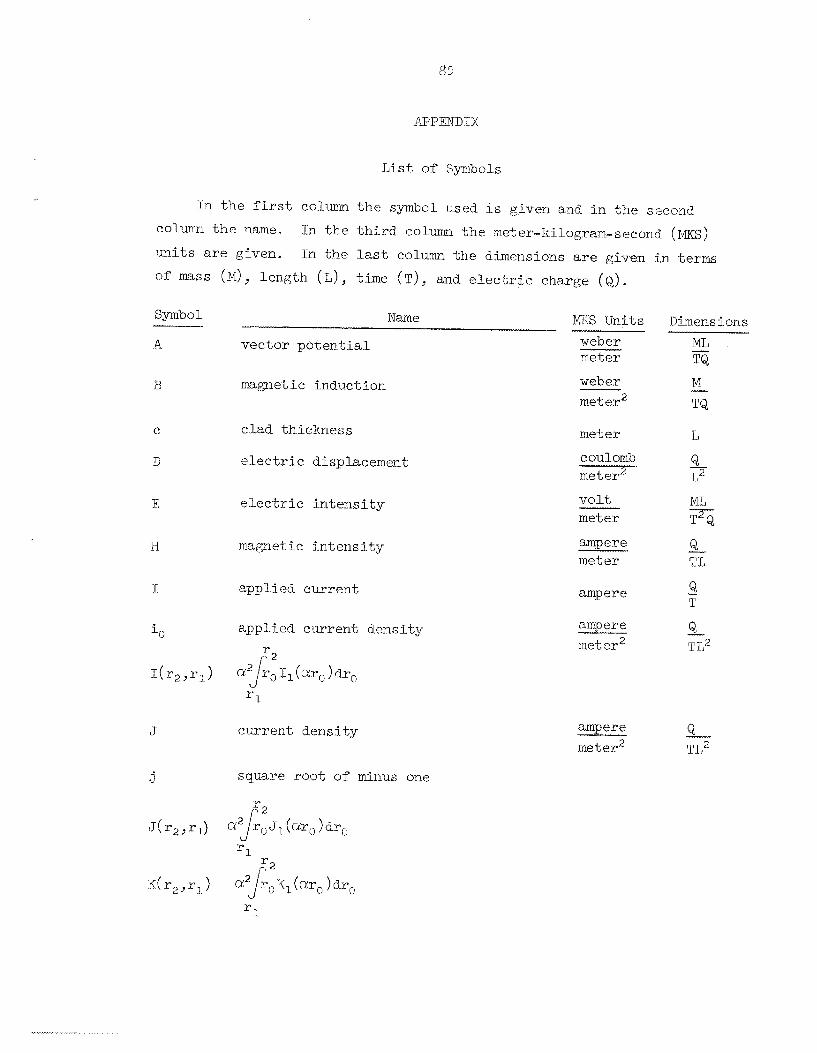
List of Symbols
- In t h e f i rs t column t h e symbol used Is given and i n t h e sqcond
coliimri t h e name.
units a r e given.
of mass (MI, length (L), time (T), and e l e c t r i c charge (Q).
In t h e t h i r d column t h e meter.-kilogram-scco.rld (MKS)
In t h e last column the dimensions are given i n t e r m
Symbol 14KS Units N a m e I-
weber meter
vector p o t e n t i a l _.-
magnetic induction weber meter2
m e t e r clad thickness
e l e c t r i c displacement coulomb meter2
e l e c t r i c i n t e n s i t y v o l t meter
magnetic interis i t y a q e r e meter
applied current ampere
app I.i u d current dens i ty
r1
ciulr ent dens i t y
square root of minus one
ampere meter‘ -I_
Dimens ions
TQ
L
Q L’
T2 Q
- Mi, -
Q - ampere --- rne t e r T L ~

86
MKS Units Dimensions __ I_-
Name .__.~_...__I S ymb o 1
L inductance henry F distance from metal t o top of the c o i l met er L a 2
J l distance from metal Lo bottom of the c o i l meter 1 1
M
N
n
t
T
v
z
mutual ind-uc tance
turns per u n i t a rea
Limber of tu rns
c o i l inner radius
c o i l outer radius
mean coil. radius
time
period
voltage
henry
1. T., - tU-Cll
meter 2
tur.11
meter L
meter L
meter 1,
second T
second T
VO 1.t
ohm
ZO distance from metal t o d e l t a function c o i l meter L
normalized i mpedamce 'n
0: separation constant
a cinrent; s ca t t w ing ma,tr%x 4
-+
1 L - 1 meter-
3. L - meter-
A
2
8 magnetic s ca t t e r inz matrix

Symbol Name MKS Units
c d i e1.e c t I- i e c- ons t ant
I-L permeah ility
meter - farad meter henrv meter
mho meter
(T conduct ivi L y
0 angular f r equ-ency second
Dimensions
1 T -


ORI\JZ- 4,384 TJC-25 - Metals, Cerartiics, and Materials
1-2. 3 .
4-23. 2,. 2'5 * 26. 27. 28. 2'3. 30.
81. 82. 83. 84.
3140
INTERNAL D I S TR IBUTIGK
1'33 , J.04, 105.
KG--115. 11.6 . 117. l l t 3 . 119. 1.20 . 121.
Centra 1 Res eareh Library GRI!IL Y- 12 Technical Library Docmen 1; Refer exie e Sect ion
Wooratory Records Depa.rtment Laboratory Records, OLNJ-RC: ORNL Patent 0:Cfi.e e 12. M. Adamson, Jr. G. E. Boyd w. 1). Brown G. W. Clark J. E. Cunningham C. V. Dodd J. 3 Frye, Jr. W P"ul.ker s on J. L. Gregg W. 0. Harm
8 547. 82 * 89. go. 91_. 92. 93. 34. * 95 * 96. 9'7 . 93. 97. 100. 101. 102.
122. 123. 124.
125-126. 1.27-128.
129. 130. 131,
132. 133-32'7-
EXTERNAL DISTRIBUTION
M. R. Hill C . E , Larson 11. G. i!~2cPherson D, L,. €Jason, Y-12 R. W. McClimng W. L. Moore H. 14. SmLYn K, E. Spear N. G. Spoeri D. A. SLmiYbeere; A. M, Weinberg V . 13. e I?. Vpplllu-ri c. M. ~ciarns, ,rr, ( ~ o n s l ~ i t a n t ) Leo Brewer. ( c o n s u l h n t ) 1,. S . Darken ( consu l t an t ) J. A. Krl-uninansl (consul tan t )
S . Aveyard, AERIE-Hxrwell, Didcot, Berkshire, Ehgland R. L. Brown, Jr., GE-Kanford D. F. Cope, RDT, SSR, AEC, Gak. Ridge IVati.ona.1 Laboratory W. E. Deeds, 'The TJriiversity of Tennessee Robert C e c.rubTriskas, Department of the A r m y , &rr!y Materials
Donald 2. Green, ADTL, Hanford W. J. h r l r i n , AN!, Oak Ridge Operations X L. Libby, (;E-Hanf or8 J. W. Lu-quire, The Tiniversi-ty of Tennessee M. C. McIlwain, K-QTJAL-AKA, C:. C. ivhrsha1.1. Space Fl.ight Center,
5. F. Pferce, 'L'h.e IJniversity of Tennessee C. J. Renken, Prgonne National Laboratory Roy S. Sharpe, AERE-Han-ell., Didcot, Berkshire, England. J. M. Simmons, A X , Washlrinqton E. E. S t a m b u r y , Tne gnriversity of Tennessee lj. K. Steveiis, AEC, Nashington J. A. Swartout, Union Carbide Corpomtion, New York D. L. WaideI-ich, Depa.rtn1en-k of ElectricEtl. Engineering,
Iabors tory and University Divi-sion, AEC, Oak R i d g e Operations Given distribution as sliown in ~ ~ i 1 - 4 5 O o under Net,als Cerarni-cs , arid Materials category
and Mechanics Research Center", Watertown, Mass .) 0%2.'72
blarshall. Center, 4-l.a. 35812
University of .Missou.ri, Colrmbia, Mo. 6520.1