(some aspects of the) physics of fast ignition -...
TRANSCRIPT

(some aspects of the)
Physics of Fast Ignitionand target studies for the HiPER project
Stefano Atzeni
Dipartimento di Energetica,Università di Roma “La Sapienza” and CNISM,Italy
IOP Plasma Physics Group Annual MeetingInstitute of Physics, London, 1–4 April 2008

Collaborators:
- A. Schiavi (Univ. Roma La Sapienza)- C. Bellei (Univ. Roma La Sapienza and Imperial College)
+ HiPER Target study group:- J. Honrubia (U. P. Madrid),- X. Ribeyre, G. Schurtz, M. Olazabal-Loumé, P. Nicolai (U. Bordeaux),- R. Evans (Imperial College)- J. Davies (IST, Lisbon)
Thanks to
- R. Betti (U. Rochester) for discussions on target simulations- M. Tabak (Livermore) for discussions on gain models- S. Baton (LULI) for materials on electron generation

Summary
Inertial confinement fusioncentral ignition vs fast ignition
Fast ignitionbasic requirementspossible schemesissues
HiPERThe projecttarget studies

Inertial confinement fusion (ICF)
• Fusion reactions • from a target containing a few mg of DT fuel • compressed to very high density (1000 times solid density)• and heated to very high temperature
• No external confinement => fuel confined by its own inertia (t = R/cs where cs is the sound speed)
• Pulsed process: for energy production• burn targets at 1 - 10 Hz• (Target gain) * (efficiency) ≥ 10
150 7%

The essential physical ingredients of ICF
• COMPRESSION, to increase burn during confinement phasedensity > 200 g/cm3 confinement: density * radius > 2 g/cm2
• HOT SPOT IGNITION, to use input energy efficiently 10 keV over a small “hot spot”

the standard approach: central ignitionimploding fuel kinetic energy converted into internal energy
and concentrated in the centre of the fuel

Central ignition ICF
Pros: Energy concentration
• in space (from target surface to hot spot)
• in time (from 10 ns laser pulse to 100 ps hot fuel confinement time)
Cons:
• high implosion velocity ==> Rayleigh-Taylor instability (RTI) at outer surface
• central hot spot ==> symmetry, inner surface RTI

a key issue for central ignition:Rayleigh-Taylor instability
deceleration-phase instability at the hot spot boundary(2D simulation)
time
=======>

Rayleigh-Taylor instability hinders hot spot formation and ignition(multimode perturbation with rms amplitude at the end of the coasting stage = 1.5 µm)
Ion temperature (eV) map evolution

A too large initial corrugation (rms amplitude 6 µm),amplified by RTI, makes hot spot formation impossible
Ion temperature (eV) map evolution

The NIF & LMJ original approachRisk reduction ==> large driver ==> low gain (*)
(*) Presently: also direct-drive seriously considered; room for substantial improvements in indirect drive, too.

Alternative ICF scheme - the fast ignitor
• Scheme: M. Tabak et al., Phys. Plasmas 1, 1626 (1994).• Ignition mechanism: S. Atzeni, Jpn. J. Appl. Phys. 34, 1980 (1995)• Ignition requirements: S. Atzeni, Phys. Plasmas 6, 3316 (1999); S. Atzeni and M. Tabak, Plasma Phys. Controll. Fusion 47, B769 (2005)
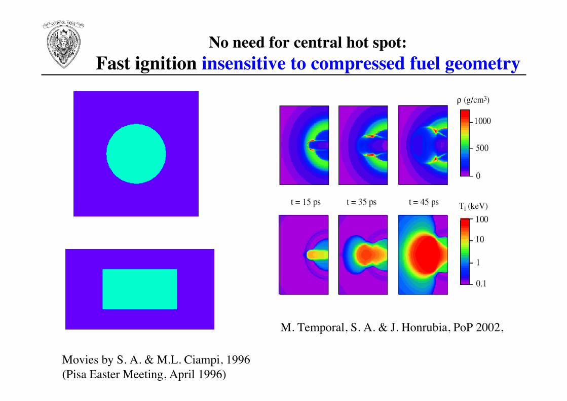
No need for central hot spot:Fast ignition insensitive to compressed fuel geometry
M. Temporal, S. A. & J. Honrubia, PoP 2002,
Movies by S. A. & M.L. Ciampi, 1996(Pisa Easter Meeting, April 1996)

No central hot spot ==> relaxed implosion symmetry
and stability requirements
Lower density ==> relaxed stability requirements ==> higher energy gain
==> lower laser energy ignition threshold

isochoric rather than isobaric ignition configuration: fast ignition allows for
- higher gain then central ignition at given driver energy
- (much) lower driver energy to achieve a given gain
isochoric vs isobaric, ideal(SA, 1995, 1999)
Fast ignition vs central ignition

The advantages of fast ignition paid by the needfor an ultra-intense (& efficiently coupled) driver
optimal parameters for density ρ = 300 g/cm3
delivered energy 18 kJspot radius 20 µmpulse duration 20 psdelivered pulse power 0.9 PWdelivered pulse intensity 7.2 x 10¹⁹ W/cm2
!
beam energy delivered to the compressed fuel
igniting laser beam energy = "ig

Nonlinear, relativistic plasma physics involved
Ultraintense laser ==> hot electrons (few MeV) ==> hot-spot creation
interaction(at critical density)
transport( 1 GA current)
deposition(in compressed
plasma)
So far, no reliable scalings for hot-e generation and transport==> We take the coupling efficiency ηig as a parameter
(with reference value of 25%)
????? see later
Hot
ele
ctro
n ge
nera
tion
effic
ienc
y
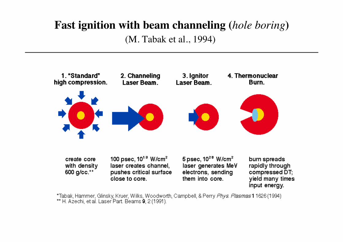
Fast ignition with beam channeling (hole boring)(M. Tabak et al., 1994)

Cone-guiding:a possible solution to shorten the path
from critical surface to compressed fuel
It seems to work! (can be scaled? see Hatchett et al. FST, 2006)

laser accelerated protons (instead of hot electrons) as ignitors:Fast ignition by laser accelerated proton beams
Petawatt- beams (5ps 6kJ)
Proton beams
Pellet
Conical shaped target
Primary driver
Converter
Radiation shields
Hohlraum
Target shield
(Roth et al, PRL 2001)
Beam requirementsfor Fast Ignition

Ignition requirements (delivered energy, power, intensity)crucially depend on fuel density ρ
!
Eig =18 "
300 g/cm3
#
$ %
&
' (
)1.85
kJ
!
Wig = 0.9 "1015 #
300 g/cm3
$
% &
'
( )
*1
W
!
Iig = 7.2 "1019 #
300 g/cm3
$
% &
'
( )
0.95
W/cm2
optimal parameters (SA, PoP 1999)
beam radius:
!
rb" 20
#
300 g/cm3
$
% &
'
( )
*0.97
µm
!
t " 20 #
300 g/cm3
$
% &
'
( )
*0.85
ps
pulse duration:
(for particles with penetration depth ≤ 1.2 g/cm2)

ignition requirements depend on fuel density,and on spot radius and particle penetration depth (R)
• for non-optimal parameters(Tabak et al. 2005, from SA’s 1999 2D simulations):
!
E ig(kJ) =18 "
300 g/cm3
#
$ %
&
' (
)1.85
*max 1,R
1.2 g/cm2
#
$ %
&
' ( * f (spot radius)
Iig(W/cm2) = 7.2 *1019 "
300 g/cm3
#
$ %
&
' (
0.95
*max 1,R
1.2 g/cm2
#
$ %
&
' ( * g(spot radius)
R
R
penetration depth R• hot-electrons: depends on hot-e temperature ==> laser I• protons: depends on p-temperature & on plasma temperature

Hot-electron temperature and range:
large uncertainties
Standard scalings
whereI = Iig/ηigfR: range multiplier
Tabak: fR = 1[Deutsch et al.: fR = 0.5]
!
Thot"el #I$2
1.2 %1019
&
' (
)
* +
1/2
MeV
Rhot"el # fR 0.6Thot"el g/cm2R
(thanks to Sophie Baton)

ignition laser energy below 100 kJ:ρ > 300 g/cm3 and
either range smaller than classicalor/and short wavelength ignition laser
ηig = 0.25
solid curves:ignition energy at given fR λ
dashed: ignition energy assumingno dependence on range, butlimitation to beam radius
dot-dashed: no dependence onrange; no limitation to beamradius
But 2ω or 3ω is expensive and transfers risk to the laser builders

For d = 3 mm and ρ = 400 g/cm3; ==> Eig > 35 kJ
Eig
* ! 90 dmm
0.7
"
100 g/cm3
#
$ % %
&
' ( (
1.3 kJ
for Tp = 5 MeV, and source - fuel distance 1 ≤ d < 4 mm
velocity dispersion -->power spread
ignition beam energy grows dramatically with distancesource-to-target
Fast ignition by laser-produced protons:• to keep power at needed level, source must be very close to the
compressed fuel
S.A. , M. Temporal, S. Honrubia,
Nuclear Fusion, 2002, L1
Cone Targets?

• 1993: fast ignition proposal
• 2001: successful integrated heating experiments at ILE Osaka (few kJ compression; 100’s J heating)
• 2008-2010: Omega EP: 30 kJ compression, 2.6 kJ heating
• 2010: FIREX: 10 kJ compression, 10 kJ heating
• Next?

A new project for fast ignition:HiPER (#)
(#) M. Dunne, Nature Phys. 2, 2 (2006);HiPER technical design report:http://www.hiper-laser.org/

Another big laser for fusion?
• two very large lasers (NIF, Livermore; LMJ, Bordeaux), designedin the early 1990’s, buing built to achieve ICF ignition.Ignition experiments planned in 2010-12
but:• large, too expensive for energy production
[NIF: 192 beams, 1.5 MJ pulses; cost > 3 G$]• low-gain targets (indirect-drive)• funded by defence programmes ==> limited access
Can one do better?potentially more efficient scheme: fast ignition
===> HiPERreduced military interest: direct-drive

HiPER: High Power Laser for Energy Research
• goal: demonstrate laser-driven inertial fusion fast ignition
• tentative main parameters:• compression pulse:
250 kJ, few ns, λc = 0.35 µm, 60 beams• ignition pulse (CPA):
70 kJ, 15 ps, λig = 0.53 µm• (preferred) scheme:
direct-drive compression, with cone-guided ignition beam
• construction cost: 900 M€• status: in the ESFRI 2006 Roadmap; Project admitted to negotiation
for EU - FP7 funds for Infrastructure Preparatory Phase (a few M€)

artist’s view
70kJ, 10psec, 1ω, 2ω or 3ω
200-300kJ, 5nsec, 3ω
a)
c)

Target studies for the HiPER project (*)
S. Atzeni, A. Schiavi, Università di Roma “La Sapienza”J. Honrubia, UPM-GIFI MadridC. Bellei, Imperial College, LondonX. Ribeyre, G. Schurtz, P. Nicolai and M. Olazabal-Loume, CELIA, BordeauxR. G. Evans, Imperial College, London and RALJ. R. C. Davies, IST, Lisbon
(*) S. Atzeni, A. Schiavi and C. Bellei, Phys. Plasmas, 14, 14052702 (2007) S. Atzeni et al., Phys. Plasmas, 15, May 2008 issue.

(INITIAL) TARGET STUDIES FOR HiPERor
What are the requirements formoderate size fast-ignition demonstrator?
• Can we ignite a target with above assumed HiPER parameters?• What else is needed?• What assumptions do we have to rely on?• What are the critical physics issues?
Next: first target overview, then “rationale” for design

reference target conceptdriven by 130 kJ compression laser
compression laser pulse • wavelength = 0.35 µm• focussing optics f/18• energy = 132 kJ
• absorbed energy = 90 kJ
ref: S. Atzeni, A. Schiavi and C. Bellei, Phys. Plasmas, 15, 14052702 (2007)

1. Laser driven implosion (1-D simulation)
• absorbed energy = 95 kJ• imploding mass = 0.29 mg• implosion velocity = 2.4 x 107 cm/s
• hydrodynamic efficiency = 10.5%• overall coupling eff. = 7.2%
• in-flight-isentrope (inner surf.) = 1.0 • IFAR at (R=0.75R0) = 36
(only one of six mesh point drawn here)
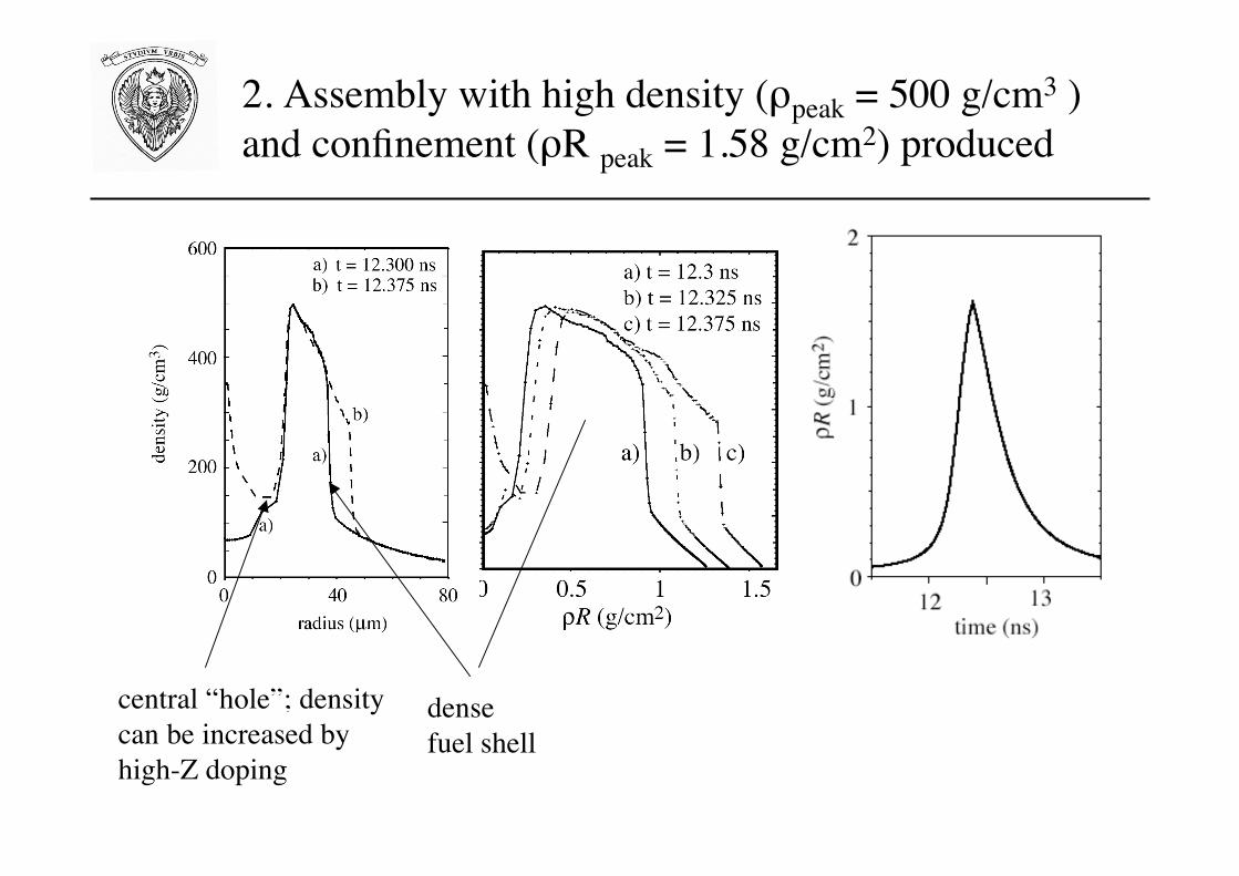
2. Assembly with high density (ρpeak = 500 g/cm3 )and confinement (ρR peak = 1.58 g/cm2) produced
central “hole”; densitycan be increased byhigh-Z doping
densefuel shell

The compressed fuel assembly can be produced by acone-guided target
By properly tuning the drivingpulse (10% P1 drive asymmetry)
• same peak density and ρ R as in 1-D simulation,• central void expelled (as seen by Hatchett et al., 2001, 2006)
(SARA code simulation)J. Honrubia, UPM-MadridIFSA 2007

density
velocity materials
temperature
But POLLUX simulations show significant shear => material mixing?
(R. G. Evans, 2007)

3. Fast ignitioninduced by a beam of particles with range = 1.2 g/cm2,delivering 20 kJ, in 16 ps, onto a spot of radius = 20 µm.
Fusion yield: 13 MJ.

Gain model and first simulations indicatepotential for high gainassuming good coupling of igniting beam to the fuel
fR λig= 0.4 µm

The rationale behind the design
maximize energy multiplication (“Gain”),while at the same time keeping risks “small” (?)
==>
• minimize compression energy (keep entropy low)• ignite at “minimum energy”
at the same time• make sure RTI growth is small• keep LPI small• try to leave safety margins
S. Atzeni, A. Schiavi and C. Bellei, Phys. Plasmas, 15, 14052702 (2007)

Ignition requirements (density, ρR)and isentrope parameter determinecompression energy and implosion velocity
From Betti and Zhou (PoP, 2005), for direct-drive targets:
!
"bulk # 0.6"peak #500
$ if
I15( )0.13 uimp
3%107cm/s
&
' (
)
* +
0.96
g/cm3
,"R-max #1.46
$ if
0.55
Ec
laser
100 kJ.a
&
' (
)
* +
0.33
g/cm2
ρbulk > 300 g/cm3 αif ≤ 1 ===> uimp > 2 x 107 cm/s
ρR > 1.2 g/cm2 compression laser energy ≥ 100 kJ
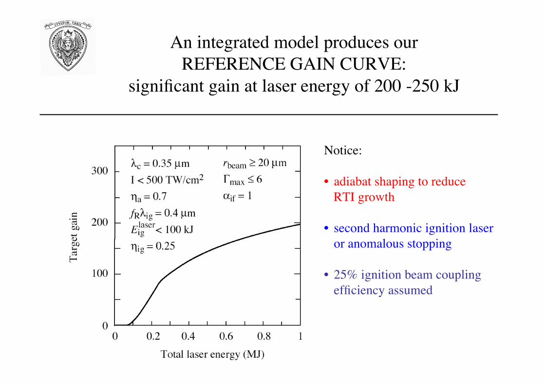
An integrated model produces ourREFERENCE GAIN CURVE:
significant gain at laser energy of 200 -250 kJ
Notice:
• adiabat shaping to reduce RTI growth
• second harmonic ignition laseror anomalous stopping
• 25% ignition beam couplingefficiency assumed

• 3 ω laser needed for compression(if 2 ω > 150 kJ required for the ignition beam)
• 2 ω (λig = 0.53 µm) ignition laser required[if 1 ω (λig = 1.06 µm): ignition threshold at 400 kJ]
flat adiabat : ignition threshold at 250 kJ(with 200 kJ for the ignition beam!)

• Simulations by CELIA(1) (CHIC code) and UPM (2) (SARAcode) confirm basic aspect of design
• Details differ due to different models & assumptions
• Same peak ρ, peak <ρR> as in previous study obtained byincreasing the total energy to about 180 kJ
(1) X. Ribeyre et al., IFSA 2007; X. Ribeyre et al., PPCF 2008(2) J. Honrubia et al., IFSA 2007

RTI growth made acceptable by adiabat shaping(Anderson-Betti’s (2004) adiabat shaping by relaxation ):Γ reduced by a factor of 1.8 two without compression degradation
standard
adiabatshaped
by integrating Takabe dispersionrelation, with 1-D flow data, overentire implosion
by PERLE perturbation code,planar, over interval oflarger acceleration (*)
adiabat shaped
(*) X. Ribeyre et al., IFSA 2007, X. Ribeyre et al., PPCF 2008

The reference target is easily scaled(mass ∝ Ec; length ∝ Ec
1/3, time ∝ Ec1/3, power ∝Ec
2/3;pulse shape needs minor tuning only)
red and green curves refer tosimulations with different electronconductivity flux-limiter and differentbremsshtralung model
scaling of density and confinement inagreement with Betti-Zhou (2005)

A large set of 2-D model-simulations (DUED code)
assuming
• spherically symmetric initial profiles generated by 1-D IMPLOsimulations, at a time close to maximum <ρR>
• cylindrical beam of igniting particles with assigned range,straight path & uniform stopping power;flat intensity profile in space and time
Hot-electron driven ignition (I)

Reference target,irradiated by a beamof particles with range = 1.2 g/cm2,focal spot radius = 20 µm, delivering20 kJ, in 16 ps.
Fusion yield = 13 MJ.
Ion temperature
density

TARGET GAIN
- (optimistically) ignition at (90+80) kJ - high gain at (250+100) kJ(critical assumptions: ignition laser coupling & hot-e coupling)
Reference
target
Compression driver energy (kJ)
90 132 270
Imploded fuel mass (mg) 0.19 0.29 0.58 peak density(g/cm3) 510 500 510 peak R(g/cm2) 1.33 1.58 1.98 Ignition driver energy (kJ), assuming ig=0.25 and optimal range, focus, etc.
72
72
72
Fusion yield(MJ) 6.6 13 3 9 GAIN 40 64 114

• Ignition is an on/off process: steep energy threshold• Particle range must fall in an appropriate window
reference target,different ranges
ignition energy vs range for thethree targets

Ignition beam to be synchronized to peakcompression within less than 100 ps(50 ps for the small target, 125 ps for the large one)

Same as in I, but including
• electron stopping and scattering (3D Monte Carlo)• electron energy distribution
Hot-electron driven ignition (II)

Coulomb interaction: stopping, straggling, scattering

Monocromatic vs Maxwellian, no scattering
(analogous to Solodov et al., PoP 2007)

Maxwellian, with scatteringDiffused heating (the more diffused, the larger d0)

velocity distribution, scatteringdistance d0 between e-source and compressed fuelraise the e-beam ignition energy
Optimal <E> = 1 -1.5 MeV (this demands 2ω or 3ω)
(2D DUED simulations for the reference target)
(similar results by Solodov et al., PoP 2007)

simulation with a hybrid code,taking self-generated fields into account
Initial configuration
Model problem:Gaussian laser pulse generates hot-e at distance d0 from blob centre,with assigned efficiency ηhot-el = 40%Electrons have 1D relativistic Maxwellian spectrum, with averageenergy as per ponderomotive scaling, and assigned divergence Θ
Hot-electron driven ignition (III)
J. Honrubia, UPM-GIFI, Madrid

•• The The e-beam e-beam energy required for ignition increasesenergy required for ignition increaseswith source-blob distance and beam divergencewith source-blob distance and beam divergence
•• Self-generated fields collimate the beamSelf-generated fields collimate the beam

Conclusions
- Key issues for moderate-energy fast ignition demonstrationidentified; gain curves computed and sensitivity analysed
- Ignition and gain with HiPER beams requires:-efficient intense laser-hot electron coupling-efficient hot electron transport-adiabat shaping to reduce RTI growth
- Reference design performed, for 130 + 80 kJ driver energy- Target easily scaled in mass and energy- Sensitivity to range, ignition beam energy, synchronization
preliminarly studied
- warning: just an initial study: complementary, but non self-consistent models; hot electron generation and transport in lowdensity plasma non included; cone poorly modeled, ...

Additional materials

Two (main) routes to ignition: merits & issues
isochoric isobaricIgnition configurationDirect heatinghydrodynamicHot spot creationFast ignitioncentral ignition
intensity ==========> symmetry <===========issues: RTinstability intensity

Ignition requirements (delivered energy, power, intensity)crucially depend on fuel density ρ
• For particles with penetration depth ≤ 1.2 g/cm2
ignition windows (S. A., PoP 1999)energy - power energy - intensity
from detailed two-dimensional numerical simulations

• Beam filamentation in the low density halo and in the ramp• [Honrubia & Meyer-ter-Vehn, Nucl. Fusion 46, L25 (2006)].• Strong ohmic heating by return currents in the halo.• Electron temperatures are lower and resistivities higher in the density
ramp, leading to a B field of 1 kT and enhanced filament growth.• Filaments carry about 10 MA each, which is almost completely
compensated by the plasma return current.• Heating of the dense core is almost exclusively by Coulomb energy
deposition.• Self-generated fields are very important for core heating indirectly by
beam filamentation and collimation.

d = 100 µm, θ = 22º, 〈E〉 = 2 MeV, e-beam energy = 27 kJ
0 100 200z (µm)
0
100
-1000 100 200
z (µm)
density ion temperature
radi
us (µ
m)
Ignition simulationIgnition simulation

0 100 200z (µm)
0
100
-1000 100 200
z (µm)
density ion temperature
radi
us (µ
m)
Ignition simulationIgnition simulation
d = 100 µm, θ = 22º, 〈E〉 = 2 MeV, e-beam energy = 27 kJ

Ignition energy can be reduced by placing the proton source very close to thecompressed fuel:
==> Conically guided target for proton beam induced fast ignition?
crucial issues:implosion symmetry, edge effects, protection of the proton source; protongeneration efficiency


Efficient burn requires ρR ≥ 1.2 g/cm2
(From 2-D simulations of fast-ignited precompressed uniform DT spheres)

At 250 kJ, gain ≥ 80at Aif ≈ 40 (IFAR ≈ 30)and compression laser intensity 3-5 x 10¹⁴ W/cm2
(for fR λig = 0.4 µm, and rbeam ≥ 20 µm)
our design point
RTI Γmax contours

- small ignition driver energy- low in-flight-isentrope- burn propagation (Φ ≥ 0.15)
!
Gain = G = Fusion energy
Driver(s) energy=
mDTQDT"
Ed -compression + Ed -ignition
!
mDT = fuel mass
QDT = 341 MJ/mg
!
Ed-ignition =Eig
"ig
= fuel ignition energy
coupling efficiency of the ignition driver
!
Ed -compression =Ec
"c
= mDT#Cd$
2 / 3
coupling efficiency of the compression driver
!
" : isentrope parameter (at ignition)
Cd = 0.31 (kJ/mg)(g/cm3)#2 / 3[ ]
!
" = burn fraction
free parameterof the model
implosion
gain at low driver energy:
Energy gain “ingredients”

Target (hollow shell)
• Fuel mass: few mg
• Radius: 1 – 3 mm
• Fuel radius / thickness = 10
Laser driver pulse
• Energy: 1 – 5 MJ
• Duration: 10 – 20 ns
• Peak power: 300 – 500 TW
• Peak intensity: 1015 W/cm2
• Wavelength: (1/4) – (1/3) µm
Compressed fuel
• Density: 200 – 1000 g/cm3
• Low average entropy,
but hot-spot with T = 10 keV