solyndra product training - ostrovní off-grid ... · light, unpacked snow 7.3 2.2 heavy, ... outer...
TRANSCRIPT

Solyndra Confidential
Solyndra Product Training
• Product details
• Installation
• Connectors
• String Design
• Fuse Calculation

Solyndra Confidential
Product Details

Solyndra Confidential3
Solyndra ProductCylindrical Modules in Panel, with Mounts Included
Panel: 40 cylindrical modules in frame
Product: Panel + mounts
Cylindrical thin film cells
in glass modules

Solyndra Confidential4
What’s Inside the Tubes?
• CIGS Thin Film: Copper, Indium, Gallium and Selenium (Diselenide)
• Film divided into ~150 cells using cutting lasers
• Cells are connected in series by internal conduction layers
• High Voltage/Low Current (more kWh/Roof Area) relative to c-Si solar panels
Solyndra Confidential5
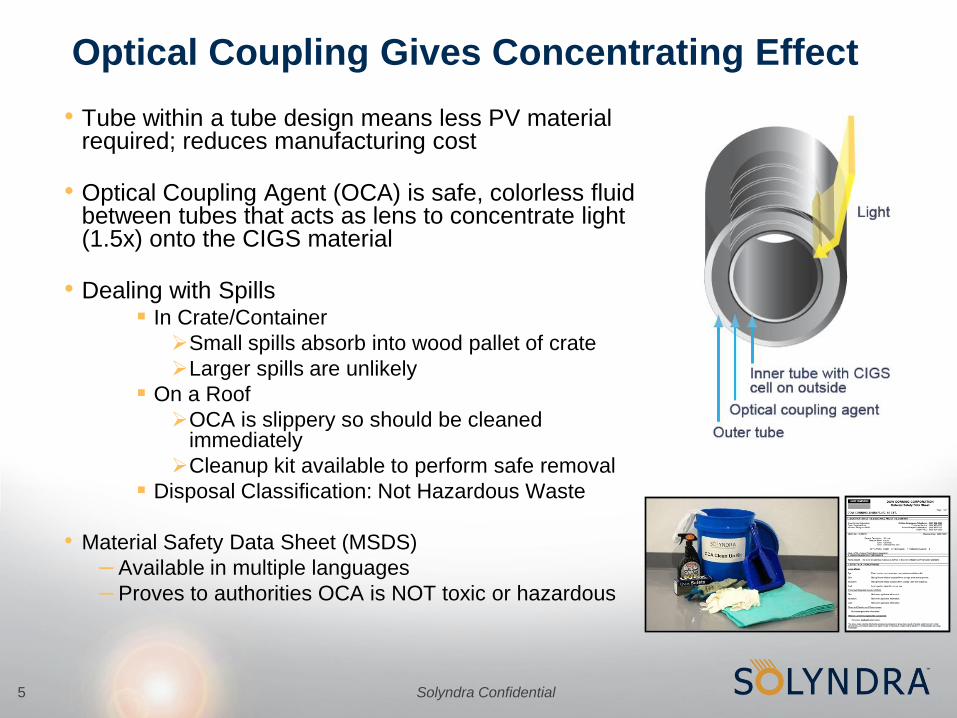
Optical Coupling Gives Concentrating Effect
• Tube within a tube design means less PV material required; reduces manufacturing cost
• Optical Coupling Agent (OCA) is safe, colorless fluid between tubes that acts as lens to concentrate light (1.5x) onto the CIGS material
• Dealing with Spills In Crate/Container
Small spills absorb into wood pallet of crate
Larger spills are unlikely
On a Roof
OCA is slippery so should be cleaned immediately
Cleanup kit available to perform safe removal
Disposal Classification: Not Hazardous Waste
• Material Safety Data Sheet (MSDS)
– Available in multiple languages
– Proves to authorities OCA is NOT toxic or hazardous

Solyndra Confidential6
Hermetically Sealed for Reliability
Conventional CIGS Panels
–Watertight package isolates
CIGS thin film materials from
moisture
–Eliminates major issue for CIGS
and ensures long-term stability
• Moisture can penetrate, forming
oxides which degrade CIGS cells
Solyndra Confidential7
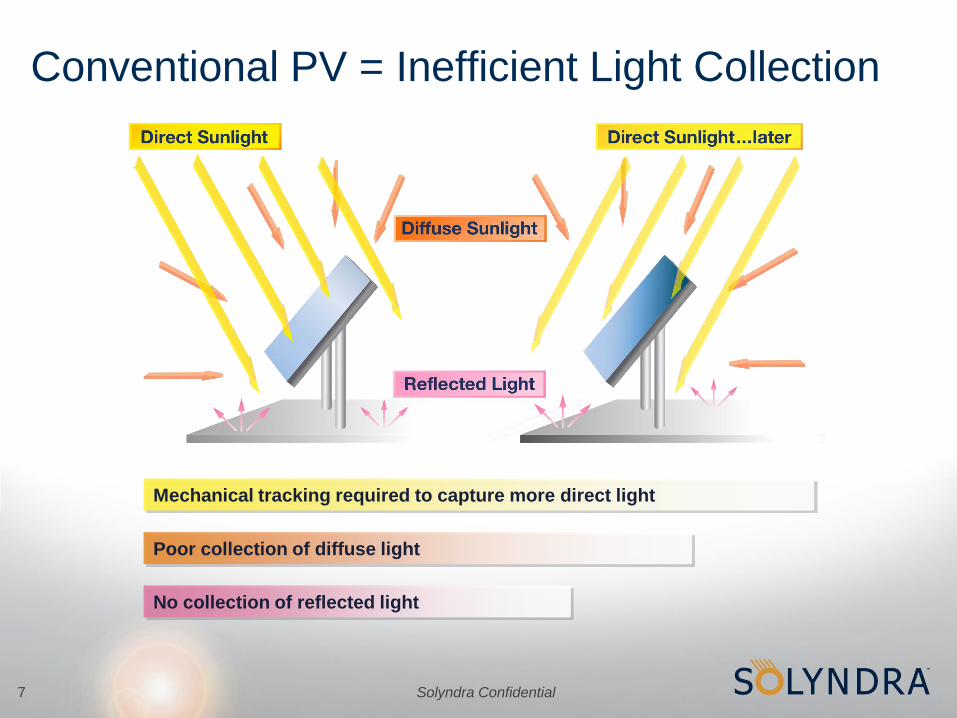
Conventional PV = Inefficient Light Collection
Mechanical tracking required to capture more direct light
Poor collection of diffuse light
No collection of reflected light

Solyndra Confidential8
Cylindrical Module = Optimized Light Collection
Horizontal mounting is optimum for solar energy
production; no need to tilt Solyndra panels
• Direct Sunlight:
Same collection at all
angles = “Self-Tracking”
• Diffuse Sunlight:
Enhanced collection
from all angles
• Reflected Sunlight:
Collection of light that
first missed tube

Solyndra Confidential9
Conventional Photovoltaic System
Higher Solar Electricity Output Per Rooftop at Lower Cost of Electricity

Solyndra Confidential10
Rooftop Example: >80% More Power and Electricity
1657.9 kWp Solyndra 907.3 kWp c-Si
c-Si panels oriented South, off building axis
to maximize efficiency
Solyndra panels can be oriented with building
axis to maximize roof coverage without
sacrificing efficiency

Solyndra Confidential11
Self Tracking = More Energy Collected• Solyndra panels capture more energy early and late in the day
versus conventional panels
• Specific Yield (kWh/kWp) a better performance metric than Wp
Solyndra vs c-Si
Fremont, CA
Timestamp: June 15, 2008

Solyndra Confidential12

Solyndra Confidential13
Minimal Building Orientation Impact on Yield
85%
90%
95%
100%
105%
-90 -75 -60 -45 -30 -15 0 15 30 45 60 75 90
Solyndra
Angled Flat PV
West South East
Panel Azimuth
Example: Sacramento, CA.. Flat panel tilt = 20°
Relative
Annual
Power
Generation
• Solyndra loss ~1% @ 45°
from South.
• Tilted PV systems at 0° on a 45° building add system complexity
and sacrifice nameplate power

Solyndra Confidential14
Self-Cleaning (Lower Soiling Loss)
Conventional Flat Plate Module
Solyndra soiling loss is ~1/2 that of titled PV panels
Dirt pools on flat surface Dirt rolls off cylinders

Solyndra Confidential15
Test Results Validate Soiling Advantage
-10%
-5%
0%
0 9 16 21 28 35 42 49
Solyndra 3 Panel Avg.
C-Si 30° Tilt
C-Si 0° Tilt
Days
Test Location: Fremont, CA. < 200 yards from I-880
Soiling
Related
Efficiency
Reduction
Solyndra soiling loss is ~1/2
that of titled PV panels.
• Cylinders prevent pooling
• Dirt falls off the steep faces
• Wind blowing through the panels
removes dry dirt.
• Morning dew beads up, runs
around, and drips off the modules.
Rain
Rain

Solyndra Confidential16
Lower Temperature Operation
Flat Plate Module With
Insulating Mounting
Conventional Flat Plate
Module & Mounting
Lower temperatures provide higher energy output and improved reliability
Air flow
Cylindrical Modules
in Panel

Solyndra Confidential17
Solyndra Cells Cooler Than Flat Plate PV
Measurements by Pt100 RTD
• on back side center of Sharp panel
• in the center of the center module of the Solyndra panel
Solyndra Confidential18
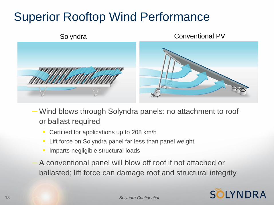
– Wind blows through Solyndra panels: no attachment to roof
or ballast required
Certified for applications up to 208 km/h
Lift force on Solyndra panel far less than panel weight
Imparts negligible structural loads
– A conventional panel will blow off roof if not attached or
ballasted; lift force can damage roof and structural integrity
Superior Rooftop Wind Performance
Conventional PVSolyndra

Solyndra Confidential19
Performance Benefit in Light Snow
• Snow falls through Solyndra
panels & enhances albedo
(~95%+ Reflectivity)
• Snow sticks to c-Si panels
and causes loss of output
Solyndra array
c-Si array

Solyndra Confidential20
2 Weeks
After Snow
Some
Bridging
Fully Bridged
Overnight
Mechanical Snow Loads
Snow Condition
ft m
Light, unpacked snow 7.3 2.2
Heavy, unpacked snow 3.2 1.0
Packed snow 1.9 0.6
Solid Ice 1.0 0.3
2800Pa
• Light snow will fall through
• Bridging in Heavy, Wet Snow
• Not an issue for panel strength in
moderate snow locations
• Solyndra max 2800 Pascal
(58.5lbs/ft2 or 285.5kg/m2)

Solyndra Confidential21
Packaged System: Panel & Simple Mounting Hardware
• Non-penetrating and self-ballasted
• Up to 3x faster installation
• Up to 2x lower installation cost
vs.
Solyndra Conventional PV
Penetrating Non/Minimally-Penetrating
or

Solyndra Confidential22
Solyndra’s Panel Mount Technology
Standard
Panel Mount(hard insulation, non-Rockwool)
Load Distributed Foot
Panel Mount (soft insulation, Rockwool)
22

Solyndra Confidential23
Solyndra Roof Loading
Panel Mount ViewsIsometric From below
Contact Area = 17.6 in2
0.12 ft2
0.01 m2
Panel
Inner Panel Mount
Outer Panel Mounts
Component Mass
Panel Weight lbs 68.3 kgs 31.0
Panel Mount Weight lbs 1.1 kgs 0.5
Mass Distribution Per Mount
Inner Panel Mount lbs 35.2 kgs 16.0
Outer Panel Mount lbs 18.1 kgs 8.2
Contact Area Forces
Inner Panel Mount lbs / ft² 287.8 kg / m² 1405
Outer Panel Mount lbs / ft² 148.2 kg / m² 724
Rooftop Distributed Load
100% Coverage lbs / ft² 3.3 kg / m² 16.3

Solyndra Confidential24
Fast, Easy, Economic Installation: Savings up to 50%
Connect Mounting Hardware Easy Panel Transport
Install ClipPlace, Plug In DC Connectors
and Ground Strap
Video

Solyndra Confidential25
50kW Customer Installation: Utah, USA
Solyndra Confidential26
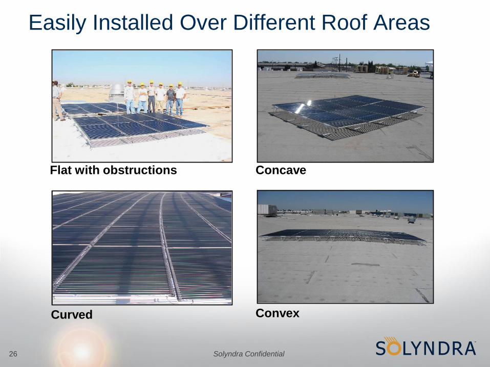
Concave
Convex
Flat with obstructions
Easily Installed Over Different Roof Areas
Curved

Solyndra Confidential27
Data Sheet: Panel Electrical Data
• Range of available panels with increasing Wp
• Higher voltage, lower current (more kWh/Roof Area) vs c-Si panels
• Low temperature coefficients: As temperature increases, power
decreases less than other panels (c-Si -0.48%/˚C, CdTe -0.25%/˚C)

Solyndra Confidential28
Data Sheet: System Information

Solyndra Confidential
Solyndra Panel Installation Training

Solyndra Confidential30
PV Panel
Modules
End Covers
Frame
Lateral Clip
Hole
Ground Strap
Panel
Mounts
Blue SOLARLOK®
Connector (negative)
Red SOLARLOK®
Connector
(positive)
Ground Lug
Hole
Product Definitions and Identification
SOLARLOK® un-keyed
connector (negative)
SOLARLOK® un-keyed
connector (positive)

Solyndra Confidential31
Safety and Handling PrecautionsTo avoid injury from electric shock or
laceration, care should be observed when
handling and working around panels.
•Don’t
• Carry a panel alone
• Handle by tubes
• Drop/place objects on panel
• Sit/Stand/Lean on panels
• Carry objects that obstruct your
view when working around panels
• Place panels where persons may
walk or trip over them
Do
• Lift with two persons
• Handle only by metal frame
• Carry one panel at a time
• Stack only in original packaging

Solyndra Confidential32
Panel Mount Description
•Panel Mount–Panel mounts are made of white powder coated aluminum and are screwed into
the long-rail side of the panel. Panels are held in place by placing panel frame
under ridge of mount.
–Panels are self-ballasting with no roof penetration required to mount.
–Mount height is standardized to clear low roof obstructions.
Panel Installation
GuideFrame Installation
Screw Hole
Foot
Ridge

Solyndra Confidential33
Provided PartsItem Picture Part # Description
Panel Mount 0040-30175
Panel mount for Solyndra photovoltaic panel. Attached using
1/4-20 screw. Because panels share panel mounts, the number
of panel mounts required will vary with each installation.
General Purpose
Screw0520-30658
M5 Phillips head with star washer, stainless steel. Used for
panel mounts, ground strap (2), lateral clip (2), and ground lug
(1). Total number required will vary with installation.
Ground Strap 0011-30029Insulated copper wire with lugs at each end. Used between the
long side of adjacent panels for array grounding.
Lateral Clip 0020-30213
Used to connect frames together with 10-32 screws. Has teeth
on one side; these go against aluminum frame to insure a good
connection.
Panel Prep Block 0205-30029Used to support the panel while installing Panel Mount. Four
are provided with each shipment.
OCA Clean-up Kit 0240-30833Clean up kit in case of panel breakage. One kit needed per
building or installation site.

Solyndra Confidential34
Optional PartsItem Picture Part # Description
Cable Tray - Long 0020-30198 Used for routing the home-run cables around the array.
Cable Tray – Short 0020-30199 Used for routing the home-run cables around the array.
Cable Tray Clip 0020-30205
The cable tray clips are installed on the short side of the panel.
They are used to support the cable tray that contains the
home-run power connections.
SolarLok female
connector (+ red ring)0710-00075
Used to connect the home-run cables to the output connection
of the strings of the array (1394462-3).
SolarLok female
connector (- blue ring)0710-00077
Used to connect the home-run cables to the output connection
of the strings of the array Tyco part number 1394462-4).
SolarLok male connector
used for ground, neutral. 0710-00379
Used to connect the home-run cables to the output connection
of the strings of the array (6-1394461-2).
SolarLok male plug 0048-30100 Used to seal unused male Tyco SolarLok connectors
SolarLok female cap 0048-30094 Used to seal unused female Tyco SolarLok connectors
Ground Lug 0700-30198
Attaches to panel with a small screw. The wire-clamping
portion is open-jawed; permits the use of a continuous length
of grounding wire. Also available as Ilsco GBL-4DBT.
Pad, Panel Mount, TPO 0020-30225Pad for panel mount - TPO type roof membrane junction, at the
option of end user.
Pad, Panel Mount, PVC 0020-30226Pad for panel mount - PVC type roof membrane junction, at the
option of end user.
Pad, Panel Mount, EPDM 0020-30227Pad for panel mount - EPDM type roof membrane junction, at
the option of end user.

Solyndra Confidential35
Recommended Installation Tools
Tyco tools for making electrical connections (jumpers & homerun leads)
Cable Stripping Tool
Tyco #1-1579002-2Crimping Tool
Tyco #1-1579004-2
Extraction Tool
Tyco #1102855-3
Small Electric Screwdriver Belt & Hardware Pouch

Solyndra Confidential36
Panel Preparation – Staging & RolesStage parts to speed installation and avoid bottlenecks
Roles People Work Description
Panel Assembly 2 Remove panels from crate and stage installation materials
Install mounts, ground straps, lateral clips and ground lugs
Manage crate materials including recyclable plastic corner pieces
Carrier/Installer 2 Move panels from assembly area to array location
Place panel with previous panels, holding while electrical connections are made
Deliver messages about panel orientation and hardware requirements
Electrical 1 Install earth ground wire to first panel in column
Attach ground straps between panels in the same column
Install lateral clips between panels in adjacent column
Connect Tyco connectors for series and parallel connections
Decide who will perform each installation function

Solyndra Confidential37
Lift panel from crate, handling only by the frame, and place on foam panel block
Panel Preparation - Handling
One person holds the panel (tube side), while the other person gets the mounts

Solyndra Confidential38
Latch 4 mounts one at a time on the panel frame with the small tab facing up.
Panel Preparation – First Panel in Column
Align the mount hole with the large hole on the panel frame. Screw in place.
Solyndra Confidential39
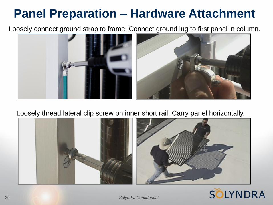
Loosely connect ground strap to frame. Connect ground lug to first panel in column.
Panel Preparation – Hardware Attachment
Loosely thread lateral clip screw on inner short rail. Carry panel horizontally.
Solyndra Confidential40
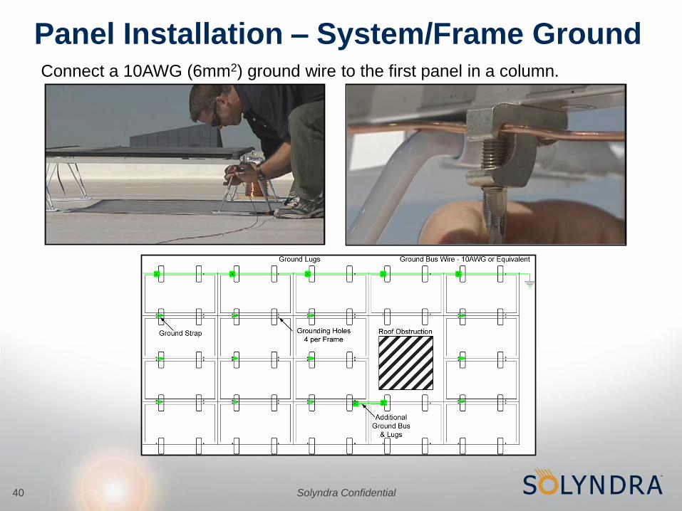
Connect a 10AWG (6mm2) ground wire to the first panel in a column.
Panel Installation – System/Frame Ground

Solyndra Confidential41
Remove the plastic pieces and set aside for recycling
Panel Preparation – Second Panel in Column
Latch only 2 mounts on the panel and install the ground strap (no lug required)

Solyndra Confidential42
Carry second panel to first panel and latch into shared mounts
Panel Preparation – Connect Second Panel
Use tab to guide panel into position. Frame ridge must be under mount ridge.
Solyndra Confidential43
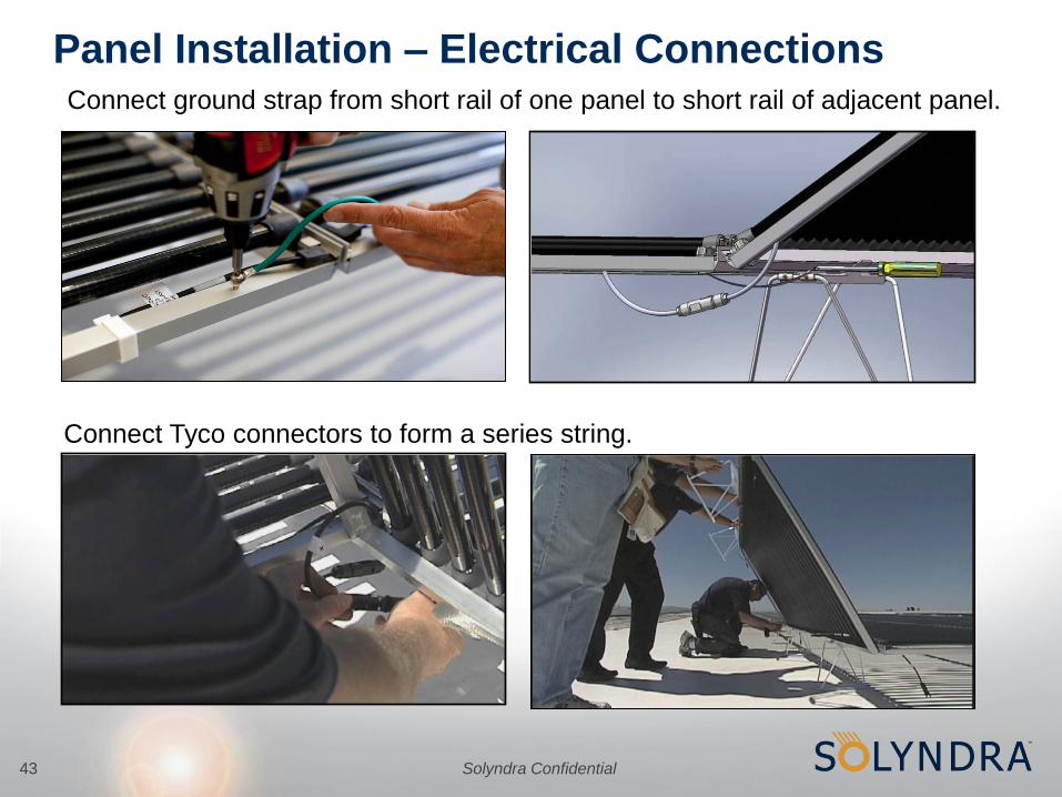
Connect ground strap from short rail of one panel to short rail of adjacent panel.
Panel Installation – Electrical Connections
Connect Tyco connectors to form a series string.

Solyndra Confidential44
Repeat steps to complete a column, checking alignment per the roof plan.
Array Origin
Panel Installation - Complete the String
Frame mis-aligned Frame aligned

Solyndra Confidential45
Loosely install lateral clip at panel prep and place panel next to first column
Panel Installation – Second Column
After attaching frame ground, secure columns together with the lateral clip

Solyndra Confidential46
Install cable tray clips on short rail. Route homerun leads in cable trays.
Panel Installation – Cable Trays
Rotate cable trays into mounts and clips, and then snap in place

Solyndra Confidential47
Connect: Array > Combiner Box > Inverter > AC Grid
Connect Leads and Inverter

Solyndra Confidential
Tyco SolarLok Connectors
Name
Date
Solyndra Confidential49
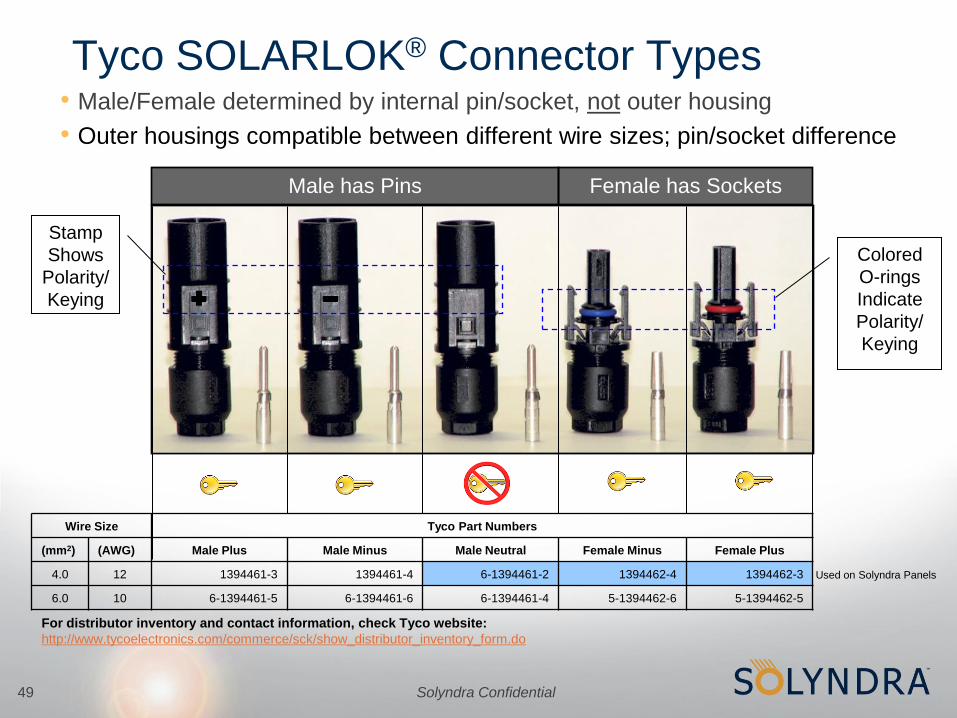
Tyco SOLARLOK® Connector Types• Male/Female determined by internal pin/socket, not outer housing
• Outer housings compatible between different wire sizes; pin/socket difference
Male has Pins Female has Sockets
Colored
O-rings
Indicate
Polarity/
Keying
Stamp
Shows
Polarity/
Keying
Wire Size Tyco Part Numbers
(mm2) (AWG) Male Plus Male Minus Male Neutral Female Minus Female Plus
4.0 12 1394461-3 1394461-4 6-1394461-2 1394462-4 1394462-3
6.0 10 6-1394461-5 6-1394461-6 6-1394461-4 5-1394462-6 5-1394462-5
Used on Solyndra Panels
For distributor inventory and contact information, check Tyco website:
http://www.tycoelectronics.com/commerce/sck/show_distributor_inventory_form.do

Solyndra Confidential50
Visual Connector Compatibility Chart
Male Neutral (Not Keyed)
Male Negative (Keyed)
• Same connectors found on
Solyndra panels.
• Use these connectors for
Homerun leads also
• Male Negative not found on
Solyndra panels
• Not compatible with female
positive (red o-ring)
connector
Male Positive (Keyed)
• Male Positive not found on
Solyndra panels
• Not compatible with female
negative (blue o-ring)
connector
Female Negative (Keyed)
Female Positive (Keyed)

Solyndra Confidential51
Optional Connector Covers
• An array of Solyndra panels will contain some open panel connectors
• Open panel connectors within the array do not pose a safety or
reliability issue, but caps/covers are available if desired.
SolarLok female cap
Solyndra part no.: 0048-30094
SolarLok male dust cover
Tyco part no.: 1394739-1
Solyndra part no.: 0048-30100

Solyndra Confidential52
Recommended Installation Tools
Tyco tools for making electrical connections (jumpers & homerun leads)
Cable Stripping Tool
Tyco #1-1579002-2
Crimping Tool
Tyco #1-1579004-2
Extraction Tool
Tyco #1102855-3

Solyndra Confidential53
Tyco SOLARLOK® Connector Assembly Steps
Step 3: Assemble Housing Notes
1. Use 4.0mm setting for Steps 1,2
2. Listen for noticeable “snap” sound
upon successful pin/socket
insertion in Step 3
Step 1: Strip Wire
Cable Stripping Tool
Tyco #1-1579002-2
Step 2: Crimp Connector
Crimping Tool
Tyco #1-1579004-2
• Homerun and string jumper cables should be constructed with Tyco SOLARLOK®
connectors for easy connection to Solyndra panel connectors.

Solyndra Confidential
String Design

Solyndra Confidential55
Panel Connector Orientation4 Connectors (Enables Series and Parallel Connections)
• Each panel has a positive and a negative side
• Modules (tubes) are connected in parallel within a harness along the panel frame
(red/blue shading)
• Each side of the panel has two connectors, one at each corner. One connector is keyed
either positive or negative, and the other is universal male. All are labeled or color coded.
Male Positive
Female Negative
Female Positive
Male Negative
+ Positive Side
- Negative Side

Solyndra Confidential56
String Building Blocks: Vertical Rectangle
Solyndra Confidential57
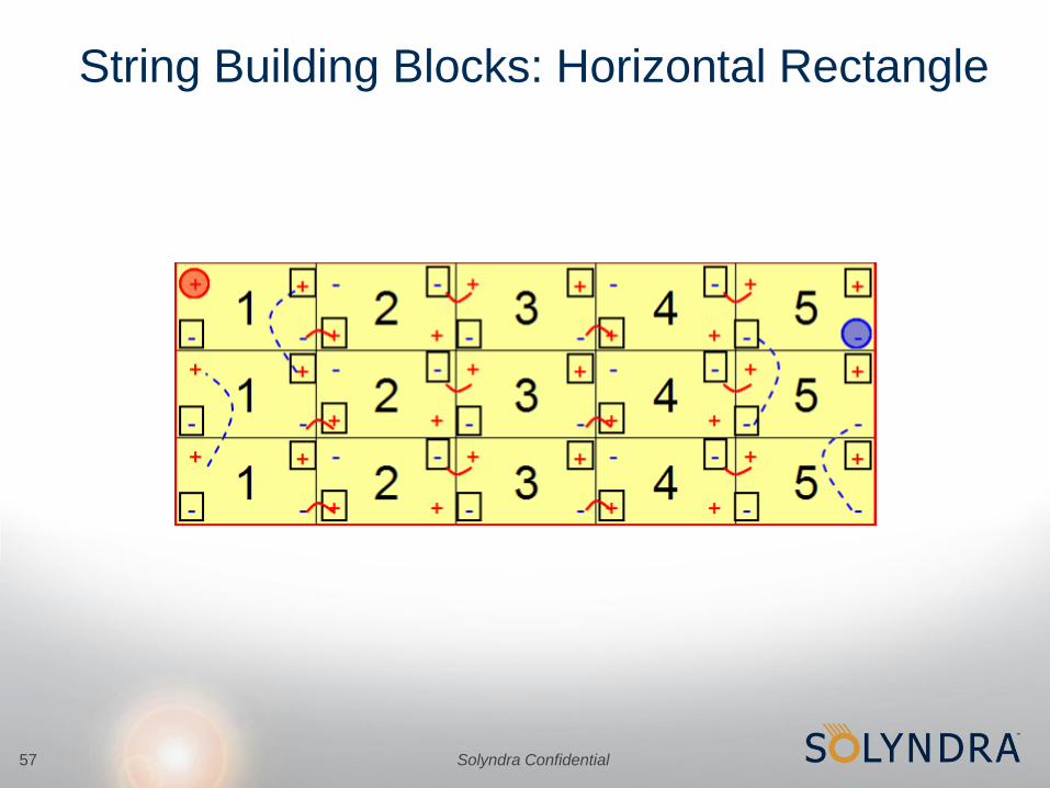
String Building Blocks: Horizontal Rectangle

Solyndra Confidential58
String Building Blocks: Combination

Solyndra Confidential59
String Building Blocks: Triangle

Solyndra Confidential60
Panel and Vertical Series String Connections
• A series string is constructed
by connecting positive and
negative panel sides
• Connections should be made
on both sides of the panel
(both sets of blue-red arrows)
for redundancy and a clean
looking installation.
• We recommend orienting
panels and strings
consistently within an array
when possible to simplify
assembly.
Positive (+) Side
Negative Side (-)
Panel Series String
Positive (+) Side
Negative Side (-)
1
2
3
4
5
N

Solyndra Confidential61
Vertical String-Block Connections
Parallel
Connections
Parallel
Connections
Series
Connections
+ +
- -
Positive
“Home Run”
Negative
“Home Run”
Negative
“Home Run”
Positive
“Home Run”
String-Block (3 Parallel Strings)
• Sub-Arrays are constructed
by connecting 3 series strings
in parallel with each other
• “Home Runs” are wired to
combiner box fused inputs or
directly to an inverter.
• Only one set of “Home Run”
points (the closest) need be
connected
• Dust caps are available to
protect unused “Home Run”
connectors.

Solyndra Confidential62
Horizontal Series String Connections
• Horizontal String Connections
+ -
Positive (+)
Side
Negative (-)
Side”Series
Connection
Series
Connection
Series
Connection
No
Connection
No
Connection
No
Connection
No
ConnectionNo
Connection
1 2 3 4
• In some cases, it may be more convenient to construct horizontal strings
which can be achieved by alternating the panel orientation
• It is important to make connections only where indicated, otherwise
shorting may occur
N
Solyndra Confidential63
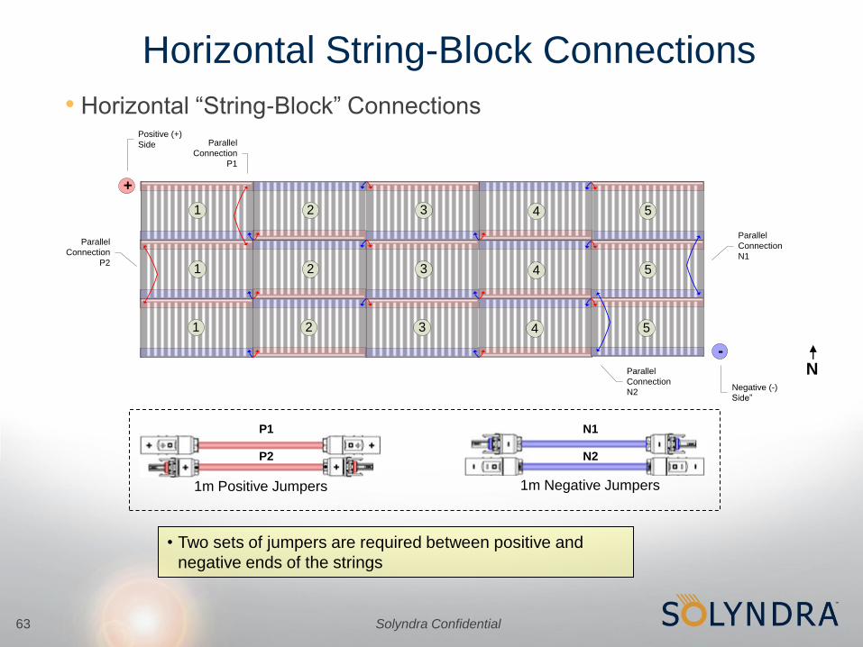
Horizontal String-Block Connections
• Horizontal “String-Block” Connections
N
+
-
Positive (+)
Side
Negative (-)
Side”
1 2 3 4 5
1 2 3 4 5
1 2 3 4 5
Parallel
Connection
P1
Parallel
Connection
P2
Parallel
Connection
N2
Parallel
Connection
N1
• Two sets of jumpers are required between positive and
negative ends of the strings
1m Positive Jumpers
P1
P2
1m Negative Jumpers
N1
N2

Solyndra Confidential64
Alternate String Connections
• “Wrapping” String Connections
+ -
Positive (+)
SideNegative (-)
Side
Series
Connections
No
Connection
1
2 3
4
• In some cases it may
be necessary to
continue a string
around a corner
(wrapping)
N

Solyndra Confidential65
Alternate String Connections
• Hybrid String Connection (Skylight Example)
N
+
-
Positive (+)
Side
Negative (-)
Side
Skylight
Skylight Setback
Series
Connection
1
2
3 4
Series Connections Series
Connection
5
Solyndra Confidential
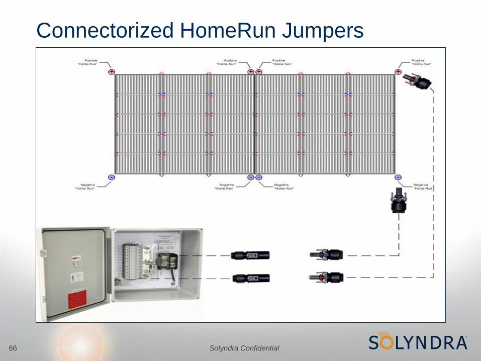
Connectorized HomeRun Jumpers
66

Solyndra Confidential67
Real World Example: Movie Theatre•130kWp, 805 Panels, 4 Different Levels, 6 Layout Shapes

Solyndra Confidential
Costco, Hazlet, NJ; 3060panels, 530kW
68

Solyndra Confidential69

Solyndra Confidential70
Importance of Array-to-Inverter Matching
• “With too few modules in series an inverter cannot maintain an array’s
MPP under high temperature conditions for the site, sacrificing energy
harvest
• Too many modules in series results in voltages above 600/1000 Vdc,
which can damage equipment, violate [local electrical] codes and void
the [inverter] manufacturer’s warranty”1
Note 1 – John Berdner, Array to Inverter Matching, SOLARPRO, December/January 2009
Maximum Series String
Length Limited By
Minimum Series String
Length Limited By
•Inverter maximum input voltage
•Wiring voltage rating
•Inverter minimum operating voltage
•Panel’s Vmp and temp coefficient of Voc
•Site temperature range

Solyndra Confidential71
Inverter Operating Range vs MPP Range
Inverter Operating Range
Inverter MPP Range
Solyndra Confidential72
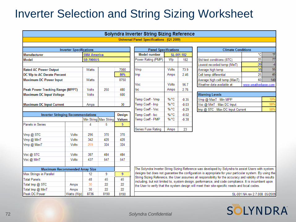
Inverter Selection and String Sizing Worksheet

Solyndra Confidential73
DC Wp to AC Derate Percent
•Real world performance typically lower than projected
–Voltage drops, panel mismatch, soiling losses reduce array output
–Inverter not always operating at peak efficiency
–Array output power lost in inversion process from DC to AC
•To make best use of inverter capacity, adjust
“DC Wp to AC Derate Percent” to match installation
conditions

Solyndra Confidential
Fuse Calculation and SFR

Solyndra Confidential75
Calculating Total Fault Current
• If a ground-fault occurs, current can back-flow through a string to ground from two sources:
–Back-feed from other parts of the array
–Other strings protected by the same fuse
• Total Fault Current that can back-flow is calculated as follows:
– IBack-feed = IFuse
– IOther strings = n-1 Strings * String Isc * 1.25
– IFault = IFuse + IOther strings
* 1.25 is a safety factor for Δ STC
fuse fuse
array
back-feed:
Gnd
Fault
Ifault
n-1 strings

Solyndra Confidential76
Calculating Fuse Sizes
•Per the U.S. National Electrical Code (NEC), fuse size is
calculated as follows:
– IFuse = 1.56 safety factor * Number of strings per fuse * Panel Isc
– Select the next largest available fuse size
•Example (3 strings of 165Wp Panels)
– IFuse = 1.56 * 3 * 2.74 = 12.82
– Next largest available fuse size is 15A

Solyndra Confidential77
Three Strings in Parallel Maximum
•Maximum Fuse Size
–IFuse = 1.56 safety factor * 3 strings * 2.77A Isc = ~13A
–Next largest available fuse size is 15A
•Maximum Fault Current < 23A Series Fuse Rating
–IFaultMax = IFuse + (n-1 Strings * String Isc * 1.25)
–Plug in known values: 23 = 15 + (n-1 * 2.77 * 1.25)
–Solve for n: ((23-15)/(2.77*1.25)) +1 = 3 Strings
–Check: 15A + (2 strings * 2.77A * 1.25 safety factor) = 21.9
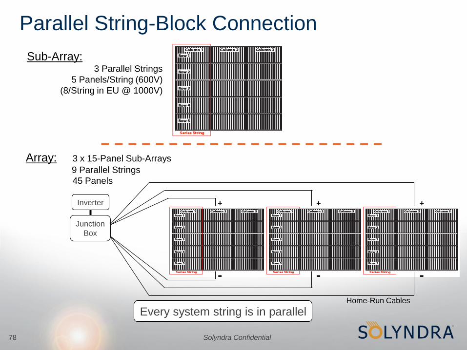
Solyndra Confidential78
Sub-Array:3 Parallel Strings
5 Panels/String (600V)
(8/String in EU @ 1000V)
Array: 3 x 15-Panel Sub-Arrays
9 Parallel Strings
45 Panels
+
-
+
-
+
-
Parallel String-Block Connection
Every system string is in parallelHome-Run Cables
Inverter
Junction
Box

Solyndra Confidential79
Questions?