solved examples for chapter 3 example 1: solutioncourses.me.metu.edu.tr/courses/me305/sert/files/me...
TRANSCRIPT
METU, ME 305, Fall 2019 Dr. Cüneyt Sert
1
Solved Examples for Chapter 3
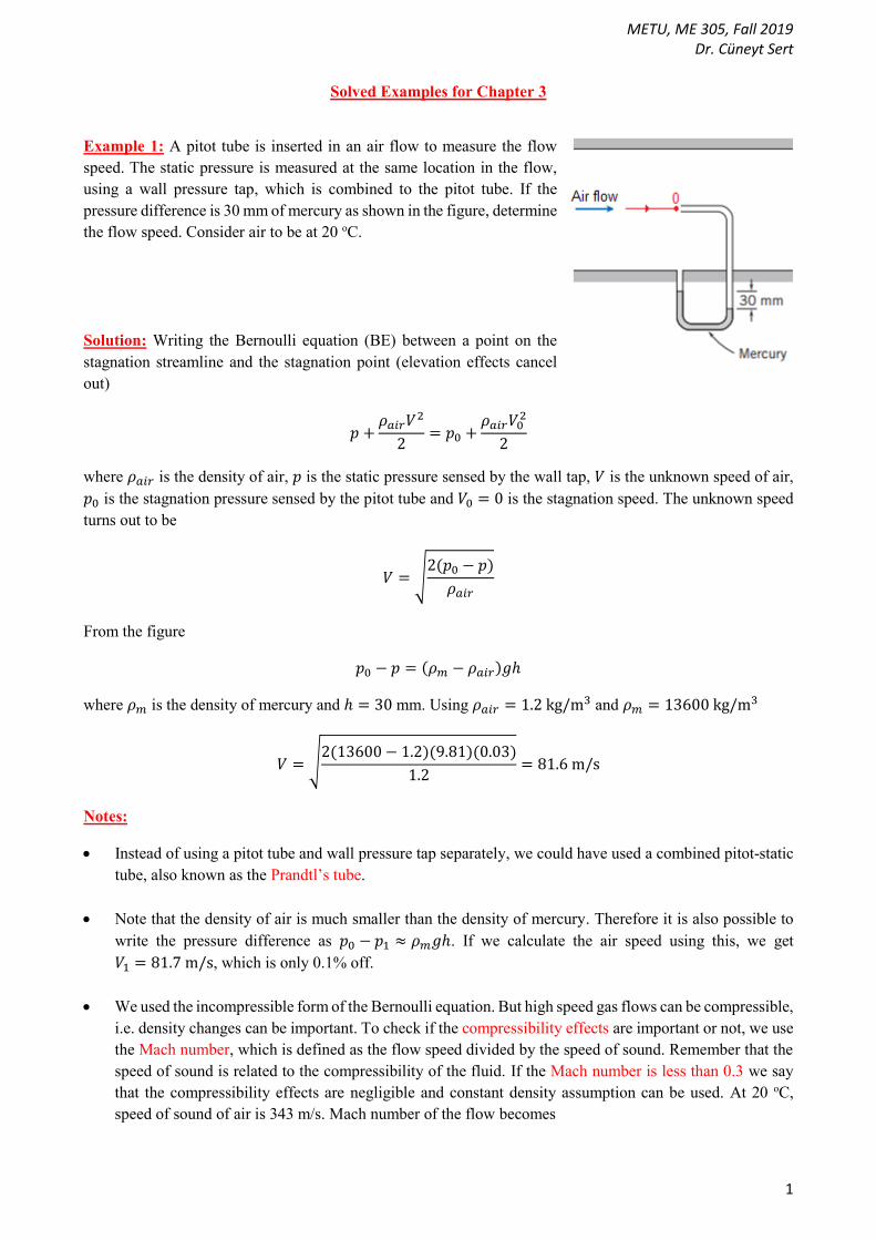
Example 1: A pitot tube is inserted in an air flow to measure the flow
speed. The static pressure is measured at the same location in the flow,
using a wall pressure tap, which is combined to the pitot tube. If the
pressure difference is 30 mm of mercury as shown in the figure, determine
the flow speed. Consider air to be at 20 oC.
Solution: Writing the Bernoulli equation (BE) between a point on the
stagnation streamline and the stagnation point (elevation effects cancel
out)
𝑝 +𝜌𝑎𝑖𝑟𝑉2
2= 𝑝0 +
𝜌𝑎𝑖𝑟𝑉02
2
where 𝜌𝑎𝑖𝑟 is the density of air, 𝑝 is the static pressure sensed by the wall tap, 𝑉 is the unknown speed of air,
𝑝0 is the stagnation pressure sensed by the pitot tube and 𝑉0 = 0 is the stagnation speed. The unknown speed
turns out to be
𝑉 = √2(𝑝0 − 𝑝)
𝜌𝑎𝑖𝑟
From the figure
𝑝0 − 𝑝 = (𝜌𝑚 − 𝜌𝑎𝑖𝑟)𝑔ℎ
where 𝜌𝑚 is the density of mercury and ℎ = 30 mm. Using 𝜌𝑎𝑖𝑟 = 1.2 kg/m3 and 𝜌𝑚 = 13600 kg/m3
𝑉 = √2(13600 − 1.2)(9.81)(0.03)
1.2= 81.6 m/s
Notes:
Instead of using a pitot tube and wall pressure tap separately, we could have used a combined pitot-static
tube, also known as the Prandtl’s tube.
Note that the density of air is much smaller than the density of mercury. Therefore it is also possible to
write the pressure difference as 𝑝0 − 𝑝1 ≈ 𝜌𝑚𝑔ℎ. If we calculate the air speed using this, we get
𝑉1 = 81.7 m/s, which is only 0.1% off.
We used the incompressible form of the Bernoulli equation. But high speed gas flows can be compressible,
i.e. density changes can be important. To check if the compressibility effects are important or not, we use
the Mach number, which is defined as the flow speed divided by the speed of sound. Remember that the
speed of sound is related to the compressibility of the fluid. If the Mach number is less than 0.3 we say
that the compressibility effects are negligible and constant density assumption can be used. At 20 oC,
speed of sound of air is 343 m/s. Mach number of the flow becomes

METU, ME 305, Fall 2019 Dr. Cüneyt Sert
2
𝑀𝑎 =𝑉
𝑐=
81.7
343= 0.24
Mach number is below the critical value of 0.3 and the flow can be considered as incompressible. For
flows with 𝑀𝑎 > 0.3, density changes become non-negligible and the compressible form of the Bernoulli
equation need to be used.
Pitot tube was invented in by Henri Pitot (1695-1711), who as a French hydraulics
engineer. Pitot invented the device in 1732 when he was assigned the task of
measuring the flow in Seine river passing through Paris. With his measurements
he disproved the common belief that speed of water increases with depth. Later
Henry Darcy modified the pitot tube into today’s form, which is used to measure
airspeed of aircrafts and helicopters, water speed of boats, and fluid speeds in
various industrial applications.
Following images show the use of pitot tube on a helicopter and an airplane.
Pitot tubes are very critical
instruments for aircrafts and their
malfunction can be catastrophic. To
measure speed, they are used
together with static ports, as seen on
the right. The warning on aircraft’s
fuselage says “Static Ports: Do not
plug or deform holes. Area within
red line must be smooth and clean”.
The pitot-static system is also used to
measure the vertical speed of the
aircraft, which is used to determine
whether or not an aircraft is flying
level. Static holes are also
responsible for measuring the altitude of the aircraft, and for this they are connected to an aneroid
barometer. The measured pressure is converted to altitude and shown in the altimeter. Several commercial
airline disasters have been traced to a failure of the pitot-static system. You can read about some of them
here: https://en.0wikipedia.org/wiki/Pitot-static_system
METU, ME 305, Fall 2019 Dr. Cüneyt Sert
3
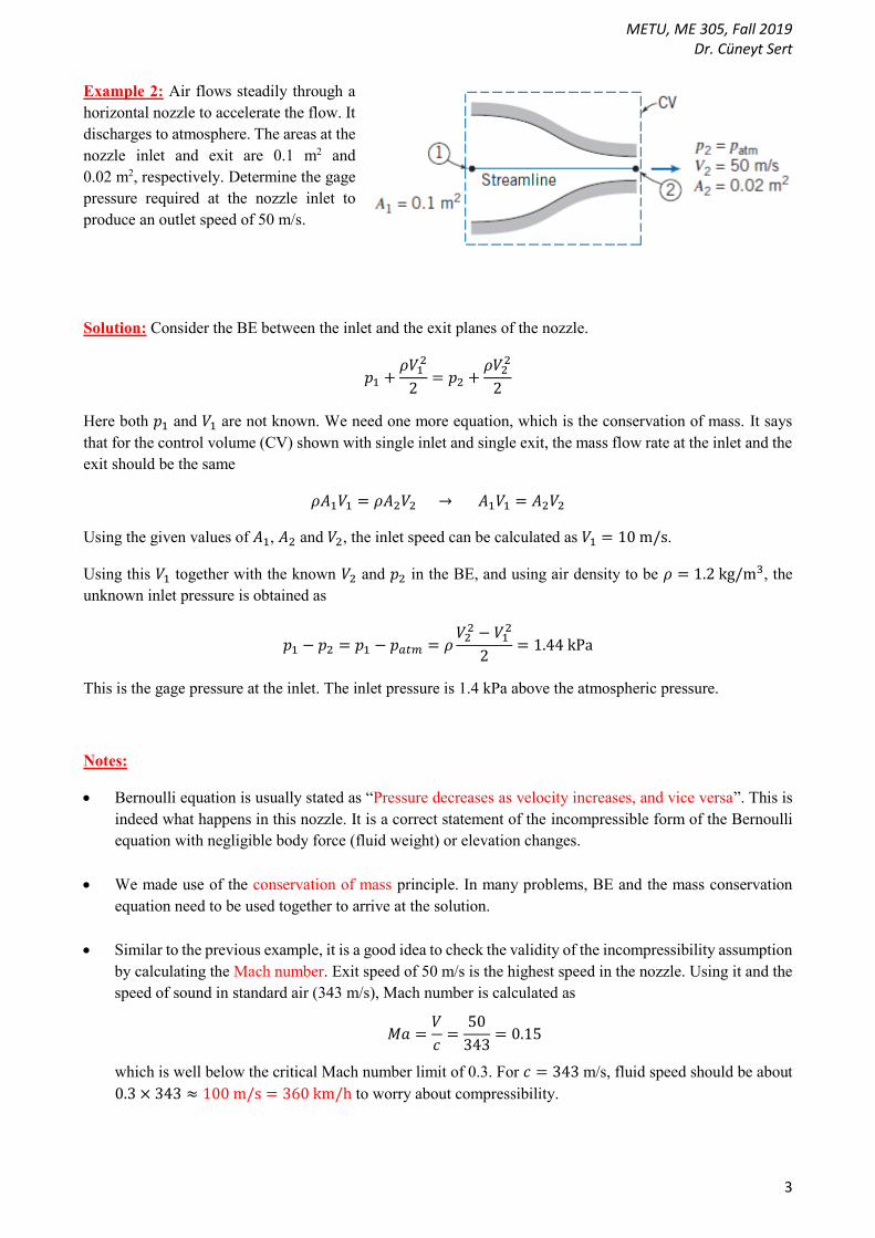
Example 2: Air flows steadily through a
horizontal nozzle to accelerate the flow. It
discharges to atmosphere. The areas at the
nozzle inlet and exit are 0.1 m2 and
0.02 m2, respectively. Determine the gage
pressure required at the nozzle inlet to
produce an outlet speed of 50 m/s.
Solution: Consider the BE between the inlet and the exit planes of the nozzle.
𝑝1 +𝜌𝑉1
2
2= 𝑝2 +
𝜌𝑉22
2
Here both 𝑝1 and 𝑉1 are not known. We need one more equation, which is the conservation of mass. It says
that for the control volume (CV) shown with single inlet and single exit, the mass flow rate at the inlet and the
exit should be the same
𝜌𝐴1𝑉1 = 𝜌𝐴2𝑉2 → 𝐴1𝑉1 = 𝐴2𝑉2
Using the given values of 𝐴1, 𝐴2 and 𝑉2, the inlet speed can be calculated as 𝑉1 = 10 m/s.
Using this 𝑉1 together with the known 𝑉2 and 𝑝2 in the BE, and using air density to be 𝜌 = 1.2 kg/m3, the
unknown inlet pressure is obtained as
𝑝1 − 𝑝2 = 𝑝1 − 𝑝𝑎𝑡𝑚 = 𝜌𝑉2
2 − 𝑉12
2= 1.44 kPa
This is the gage pressure at the inlet. The inlet pressure is 1.4 kPa above the atmospheric pressure.
Notes:
Bernoulli equation is usually stated as “Pressure decreases as velocity increases, and vice versa”. This is
indeed what happens in this nozzle. It is a correct statement of the incompressible form of the Bernoulli
equation with negligible body force (fluid weight) or elevation changes.
We made use of the conservation of mass principle. In many problems, BE and the mass conservation
equation need to be used together to arrive at the solution.
Similar to the previous example, it is a good idea to check the validity of the incompressibility assumption
by calculating the Mach number. Exit speed of 50 m/s is the highest speed in the nozzle. Using it and the
speed of sound in standard air (343 m/s), Mach number is calculated as
𝑀𝑎 =𝑉
𝑐=
50
343= 0.15
which is well below the critical Mach number limit of 0.3. For 𝑐 = 343 m/s, fluid speed should be about
0.3 × 343 ≈ 100 m/s = 360 km/h to worry about compressibility.
METU, ME 305, Fall 2019 Dr. Cüneyt Sert
4
The speeds at the inlet and exit are the average speeds. Actually due to the no-slip condition, the speed
should be zero at the nozzle wall and we expect to have the maximum speed on the nozzle centerline. But
the BE neglects the viscous effects, meaning that it also disregards the no-slip condition.
We know that exit pressure of an incompressible fluid jet is equal to the surrounding pressure. That is
why the exit pressure is considered to be atmospheric pressure in this example.
It is interesting and puzzling for some students that the flow in this nozzle is steady although the fluid
particles accelerate in it. When you focus on a fluid particle, it experiences an acceleration, i.e. its speed
increases as it travels inside the nozzle. But to decide on steadiness or unsteadiness we do not focus on
fluid particles. Instead we focus on different locations of the problem domain and see if things change in
time or not. For example, we consider the inlet of the nozzle and see that the fluid always enters at 10 m/s
speed and 1.44 kPa gage pressure. These values do not change with time. Similarly, the fluid always exits
the nozzle at 50 m/s speed and zero gage pressure. These also do not change with time. Based on these,
we say that this nozzle operates steadily and the steady form of the BE can be used.
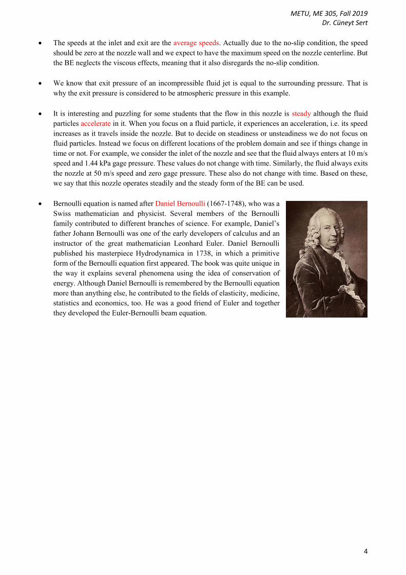
Bernoulli equation is named after Daniel Bernoulli (1667-1748), who was a
Swiss mathematician and physicist. Several members of the Bernoulli
family contributed to different branches of science. For example, Daniel’s
father Johann Bernoulli was one of the early developers of calculus and an
instructor of the great mathematician Leonhard Euler. Daniel Bernoulli
published his masterpiece Hydrodynamica in 1738, in which a primitive
form of the Bernoulli equation first appeared. The book was quite unique in
the way it explains several phenomena using the idea of conservation of
energy. Although Daniel Bernoulli is remembered by the Bernoulli equation
more than anything else, he contributed to the fields of elasticity, medicine,
statistics and economics, too. He was a good friend of Euler and together
they developed the Euler-Bernoulli beam equation.

METU, ME 305, Fall 2019 Dr. Cüneyt Sert
5
Example 3: During a trip, a car runs out of gasoline, and it
becomes necessary to siphon gas out of another car’s gas tank.
The siphon is a small-diameter tube, and to use it we insert one
of its ends in the full gas tank, fill the tube with gasoline by
applying initial suction, and then place the other end below the
level of the gas tank. The difference in pressure between point
1 (free surface of the gasoline in the tank) and point 2 (outlet
of the tube) causes the liquid to flow from the higher to the
lower elevation. Once the initial flow is established by sucking
the air out of the tube, the gasoline will flow out by itself.
Determine (a) the speed of the gasoline at the exit of the tube,
(b) the minimum time to withdraw 4 L of gasoline from the
tank and (c) the pressure at point 3. The density of gasoline is
750 kg/m3. Atmospheric pressure is 101 kPa. The siphoning
tube diameter is 5 mm.
Solution: a) This is a classical example for the use of the Bernoulli equation (BE). Assuming the frictional
effects inside the tube to be negligibly small, write the BE between points 1 (at the free surface in the gas tank)
and 2 (exit of the siphoning tube)
𝑝1 +𝜌𝑉1
2
2+ 𝜌𝑔𝑧1 = 𝑝2 +
𝜌𝑉22
2+ 𝜌𝑔𝑧2
Free surface of the gas tank is exposed to the atmospheric pressure (𝑝1 = 𝑝𝑎𝑡𝑚).
We know that the exit pressure of an incompressible fluid jet is equal to the surrounding pressure. In
our case this makes the pressure at the exit of the tube be the atmospheric pressure (𝑝2 = 𝑝𝑎𝑡𝑚).
𝑉1 is the velocity of the free surface inside the gas tank. It is a small value for a large tank, and it will
be taken as zero here (𝑉1 ≈ 0).
𝑧1 − 𝑧2 = 0.75 m.
The only unknown in the BE is 𝑉2, which is the speed of the gas exiting the tube.
𝑉2 = √2𝑔(𝑧1 − 𝑧2) = √2(9.81)(0.75) = 3.84 m/s
b) As seen, the speed of the exiting gasoline is related to the height difference 𝑧1 − 𝑧2. Therefore, as the
gasoline flows out of the tank, 𝑧1 − 𝑧2 difference and the exit speed will decrease. To have an estimate about
the minimum time required to withdraw a certain amount of gasoline, we can assume the exit speed to remain
constant at the calculated value. This will result in a constant flow rate of
𝑄 = 𝑉2𝐴2 = (3.84) (𝜋(0.005)2
4) = 7.54 × 10⁻⁵ m3/s = 7.54 × 10⁻² L/s
To withdraw ∀= 4 liters of gasoline, we need
Δ𝑡 =∀
𝑄=
4
7.54 × 10−2= 53 s
METU, ME 305, Fall 2019 Dr. Cüneyt Sert
6
As explained above, this is a minimum time estimate. The actual time required for the withdrawal will be
larger than this. If the geometric details of the gas tank are known, a more detailed and more correct calculation
can be done.
c) Write the BE between points 3 and 2
𝑝3 +𝜌𝑉3
2
2+ 𝜌𝑔𝑧3 = 𝑝2 +
𝜌𝑉22
2+ 𝜌𝑔𝑧2
𝑝2 = 𝑝𝑎𝑡𝑚
𝑉2 = 3.84 m/s
𝑉3 = 𝑉2 due to the conservation of mass principle. The same flow rate should pass through sections 2
and 3, i.e. 𝐴2𝑉2 = 𝐴3𝑉3. Tube cross sectional area is constant, therefore, average speeds should be the
same.
𝑧3 − 𝑧2 = 2.75 m
The only unknown in the BE is 𝑝3, which can be calculated as
𝑝3 = 𝑝2 + 𝜌𝑔(𝑧2 − 𝑧3) = 101000 + (750)(9.81)(−2.75) = 80766 Pa ≈ 81 kPa
Notes:
The fact that “the exit pressure of an incompressible fluid jet is equal to the surrounding pressure” is
useful in applying the BE to many problems. Do not forget it.
The equation derived for 𝑉2 in part (a) is nothing but the Toricelli equation derived in class.
It is interesting to note that the result of part (a) is independent of the tube diameter. In reality the flow
inside the tube is not frictionless, i.e. it is viscous. We should always be careful when neglecting friction
in an internal flow such as flow inside a pipe or a duct. In this problem, neglecting friction is reasonable
if the tube is relatively short and its diameter is not too small. Frictional effects will increase as the tube
gets longer and as its diameter gets smaller. We will learn how to extend the BE to account for the viscous
forces in the last chapter of ME 305.
It is important to understand that point 1 is at the free surface in the gas tank. It is not at the entrance of
the tube inside the tank. Point 1 is selected at the free surface because it is good reference point with
known elevation and negligible speed.
What happens if in part (a) we use the BE between a new point, point 4 at the entrance of the tube and
point 2? Let’s pretend that elevation of this new point 4 is known.
𝑝4 +𝜌𝑉4
2
2+ 𝜌𝑔𝑧4 = 𝑝2 +
𝜌𝑉22
2+ 𝜌𝑔𝑧2
This equation is not useful to calculate 𝑉2. Point 4 is at the entrance of the tube and if the tube has constant
cross-sectional area, the speed at the entrance and the exit of the tube should be the same to conserve
mass, i.e. 𝑉4 = 𝑉2. The velocity terms cancel out.
Part (c) can also be solved by writing the BE between points 1 and 3. Try it and see if you can get the
same answer or not.
METU, ME 305, Fall 2019 Dr. Cüneyt Sert
7
If the elevation difference between points 1 and 3 is too high, the pressure at point 3 may drop too much
such that the tube may collapse if it is made of soft plastic, i.e. not rigid enough. This may block the flow
of gasoline.
Also if this elevation difference is high enough, the pressure at point 3 may fall down to the vapor pressure
of gasoline, and some gasoline may evaporate (cavitate). The formed vapor may form a pocket at the top,
blocking the flow. What is the vapor pressure of gasoline at 20 oC and at what 𝑧3 − 𝑧1 difference will this
occur?
Note that we did not bother to check the incompressibility assumption because liquids can very safely be
treated as incompressible in almost all applications.
We neglected the speed of the free surface in the gas tank, thinking that it is much smaller than the speed
inside the tube, i.e. 𝑉12 ≪ 𝑉2
2. See the next example for a problem where the free surface speed is not
neglected.
METU, ME 305, Fall 2019 Dr. Cüneyt Sert
8
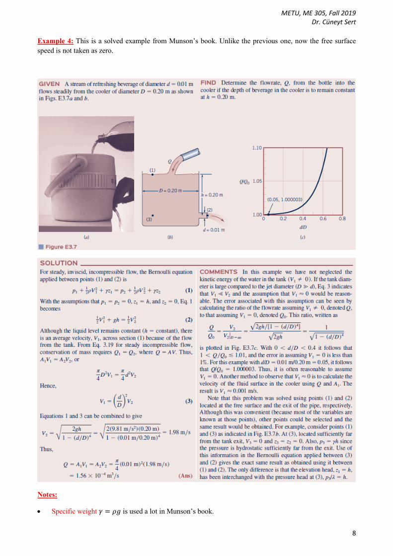
Example 4: This is a solved example from Munson’s book. Unlike the previous one, now the free surface
speed is not taken as zero.
Notes:
Specific weight 𝛾 = 𝜌𝑔 is used a lot in Munson’s book.

METU, ME 305, Fall 2019 Dr. Cüneyt Sert
9
Example 5: This is another solved example from Munson’s book.

METU, ME 305, Fall 2019 Dr. Cüneyt Sert
10
Example 6: Air is drawn into a wind tunnel used for testing automobiles as shown.
a) Determine the manometer reading, ℎ, when the velocity in the test section is 100 km/h. Note that there is
water in the manometer, as well as 2.5 cm column of oil with specific gravity 0.9.
b) Determine the difference between the stagnation pressure on the front of the automobile and the pressure
in the test section.
Solution: Consider the following horizontal streamline that starts from outside the tunnel and ends at the
stagnation point. Pick 3 points on it.
a) Write the BE between points 1 and 2 (elevations cancel out)
𝑝1
𝜌𝑔+
𝑉12
2𝑔=
𝑝2
𝜌𝑔+
𝑉22
2𝑔
With
𝑝1 = 𝑝𝑎𝑡𝑚
𝑉1 ≈ 0 (air speed outside the tunnel is low)
𝑉2 = 100 km/h = 27.8 m/s (given)
BE simplifies to
𝑝𝑎𝑡𝑚 − 𝑝2 = 𝜌𝑉2
2
2𝑔
𝑝2 is measured by the manometer as follows (density of air is much smaller than the density of water and
mercury, so the effect of air column is negligible).
𝑝2 + 𝜌𝑤𝑎𝑡𝑒𝑟𝑔ℎ − 𝜌𝑜𝑖𝑙𝑔(0.025) = 𝑝𝑎𝑡𝑚
Substituting this into the BE, we get
𝜌𝑤𝑎𝑡𝑒𝑟𝑔ℎ − 𝜌𝑜𝑖𝑙𝑔(0.025) = 𝜌(27.8)2
2𝑔
1 2 3
METU, ME 305, Fall 2019 Dr. Cüneyt Sert
11
Using 𝜌𝑤𝑎𝑡𝑒𝑟 = 1000 kg/m3, 𝜌𝑜𝑖𝑙 = 900 kg/m3 and 𝜌 = 1.2 kg/m3 (density of air), the unknown height can
be calculated as
ℎ = 0.006 m = 6 mm
b) Write the BE between points 2 and 3 (elevations cancel out)
𝑝2
𝜌𝑔+
𝑉22
2𝑔=
𝑝3
𝜌𝑔+
𝑉32
2𝑔
We know that 𝑉3 = 0.
𝑝3 − 𝑝2 = 𝜌𝑉2
2
2𝑔= (1.2)
(27.8)2
2(9.81)= 47.3 Pa
Notes:
This example is similar to the one we solved in class, in which we calculated the stagnation pressure at the
front of a car. That example was unsteady in its original form and we converted it to steady form by
changing the coordinate system. Here we do not need to do that because the problem is already steady. In
the example we solved in class air at a certain speed and atmospheric pressure was coming to a stop at the
front of the car. Here it is not like that. Here the atmospheric air outside the tunnel is almost stagnant.
Make sure that you understand the differences between these problems.
It is important to note that the pressure at point 3 is equal to 𝑝𝑎𝑡𝑚. By the help of the fan, almost stagnant
air at atmospheric pressure is sucked into the tunnel. Its velocity increases and its pressure decreases inside
the tunnel. Some of the accelerated fluid particles reach the stagnation point at the front of the car and in
doing so their speed decreases and pressure increases. By neglecting any frictional (viscous) effects, which
are quite negligible in this case, the air returns to its original state, i.e. 𝑉3 = 𝑉1 = 0 and 𝑝3 = 𝑝1 = 𝑝𝑎𝑡𝑚.

METU, ME 305, Fall 2019 Dr. Cüneyt Sert
12
Example 7: Water is discharging from a large reservoir through
an inclined variable diameter pipe. Show the energy line and the
hydraulic grade line. Use gage pressures. Gage pressure at the free
surface and the exit is zero.
Solution: Let’s pick 3 points as shown below. The first and the third points are exposed to atmospheric
pressure, i.e. zero gage pressure (𝑝1 = 𝑝3 = 0 gage). The first point, located on the large free surface, has
negligible speed (𝑉1 ≈ 0).
Point 1: Pressure (gage) head = 0, Velocity head = 0, Elevation head = 𝑧1
Point 2: Pressure (gage) head = 𝑝2/𝜌𝑔, Velocity head = 𝑉22/2𝑔, Elevation head = 𝑧2
Point 3: Pressure (gage) head = 0, Velocity head = 𝑉32/2𝑔, Elevation head = 𝑧3
BE says that the total head is constant, i.e.
0 + 0 + 𝑧1 = 𝑝2
𝜌𝑔+
𝑉22
2𝑔+ 𝑧2 = 0 +
𝑉32
2𝑔+ 𝑧3 = constant
The energy line (EL) is a horizontal line showing the total head. Using the first point, the total head is equal to
𝑧1.
To draw the hydraulic grade line (HGL) we subtract the velocity head, i.e. 𝑉2/2𝑔 from the EL line.
In doing this, we know that 𝑉3 > 𝑉2 because of the steady, incompressible mass conservation principle
(𝐴2𝑉2 = 𝐴3𝑉3) and the cross sectional areas are related as 𝐴3 < 𝐴2.
1
𝑧 2
”
1
2
3
𝑧1
EL
𝑧3
𝑧2
𝑉22
2𝑔
𝑉32
2𝑔
HGL
𝑝2
𝜌𝑔
𝑧

METU, ME 305, Fall 2019 Dr. Cüneyt Sert
13
Notes:
HGL line shows the sum of the elevation and pressure heads. In drawing it, we first located the HGL level
at point 1. It is the same as the EL level because the speed at point 1 is zero. Next, we located the HGL
level at point 3, which is the 𝑧3 level because 𝑝3 = 0 (gage). Finally, we located the level at point 2 as an
arbitrary level, somewhere between the levels of points 1 and 3.
As seen, HGL line stays horizontal as long as the flow cross sectional area is constant. It is because the
difference between the EL and HGL lines is the velocity head, which is constant for constant flow cross
sectional area.
When the flow cross sectional area changes, speed changes and that is when the level of HGL changes.
Consider a 4th point inside the smaller
diameter pipe, as shown below.
𝑉4 = 𝑉3 and the velocity heads of the
points 3 and 4 are the same. As seen,
the pressure head of point 4 is negative.
This means that the gage pressure at
point 4 is negative, which is possible.
As a fluid particle moves down inside the smaller diameter pipe, its kinetic energy remains the same
(because its velocity remains the same), its potential energy decreases, and to have a balance in the BE,
its pressure increases. Therefore, if the fluid particle exits from the pipe with atmospheric pressure, the
pressure inside the pipe should be lower than the atmospheric pressure.
Actually, the pressure inside the larger diameter pipe can also be negative gage, i.e. the green pressure
head arrow of point 2 in the first figure can also be pointing downwards, although we showed it upwards.
As noted before, the level of HGL at point 2 is selected arbitrarily between the levels of points 1 and 3.
We have to do an arbitrary selection because we don’t have numerical values for the elevations and speeds.
We do not know for sure whether the pressure inside the larger pipe is negative gage or not (it depends
on the elevations and the flow speed inside the pipe), but we know for sure that the pressure inside the
smaller pipe is negative gage.
For some students it may be hard to accept that the kinetic energy of the fluid going downward in a
constant diameter pipe does not change. They think that as the fluid goes downward in a pipe it will speed
up. No, it won’t. Similarly, as a fluid goes upward in a pipe it won’t slow down. For a steady
incompressible flow, the fluid speed inside a pipe would not change as long as the cross sectional area of
the pipe remains the same. This is what the conservation of mass says. What changes with elevation is the
pressure, not the speed. Having constant speed in a steady liquid flow inside a constant diameter pipe has
nothing to the with the Bernoulli equation. It has nothing to do with the neglected frictional effects. It is
due to the conservation of mass. Even if we include frictional effects, the speed would still remain
4
EL
𝑧4
𝑉42
2𝑔
𝑝4/𝜌𝑔
HGL

METU, ME 305, Fall 2019 Dr. Cüneyt Sert
14
constant. What changes due to friction would again be pressure. Friction would cause additional pressure
drop in the flow direction, which will be studied in the last chapter of ME 305.
It is possible to work with absolute pressures instead of gage pressures. Although some of you may find
this more natural, it is not necessary and it is not advised. The EL and HGL lines when we use absolute
pressures will be as follows. They are the same as before, but shifted upwards by an amount of 𝑝𝑎𝑡𝑚/𝜌𝑔.
In this drawing the HGL levels are also shown somewhat arbitrarily, because we do not have numerical
values to calculate the actual heads.
When we use the absolute pressures the green pressure head arrows should always point upwards, because
an absolute pressure cannot be negative.
If we insert pitot tubes inside the pipes, the liquid level
in them will be up to the EL (but the EL drawn using
gage pressures, not absolute pressures). Also if we drill
holes to the pipes and attach piezometers, the liquid
levels in them will be up to the HGL line (again the line
drawn using gage pressures, not absolute). Here it is
interesting to note that the HGL level in the smaller
diameter pipe is below the pipe itself. Therefore, for
example at point 4, using just a vertical piezometer tube
will not work. At point 4 there is negative gage pressure
and if we drill a hole at that location and attach a vertical
piezometer, we won’t be able to see any liquid inside it,
but the atmospheric air will be sucked into the pipe.
Instead of a vertical piezometer, we need to use a U-
tube manometer as sketched below. The liquid level
inside this manometer will be the HGL level.
𝑝2
𝜌𝑔
1
𝑧 2
”
1
2
EL
𝑧1
𝑉22
2𝑔
𝑉32
2𝑔
3 𝑧3
𝑧2
HGL
𝑝3
𝜌𝑔
𝑝1
𝜌𝑔
4
Negative gage pressure head
HGL
METU, ME 305, Fall 2019 Dr. Cüneyt Sert
15
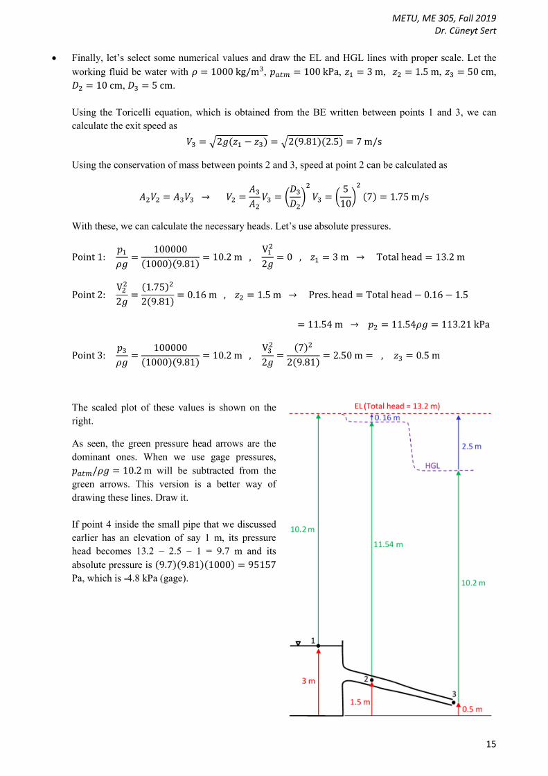
Finally, let’s select some numerical values and draw the EL and HGL lines with proper scale. Let the
working fluid be water with 𝜌 = 1000 kg/m3, 𝑝𝑎𝑡𝑚 = 100 kPa, 𝑧1 = 3 m, 𝑧2 = 1.5 m, 𝑧3 = 50 cm,
𝐷2 = 10 cm, 𝐷3 = 5 cm.
Using the Toricelli equation, which is obtained from the BE written between points 1 and 3, we can
calculate the exit speed as
𝑉3 = √2𝑔(𝑧1 − 𝑧3) = √2(9.81)(2.5) = 7 m/s
Using the conservation of mass between points 2 and 3, speed at point 2 can be calculated as
𝐴2𝑉2 = 𝐴3𝑉3 → 𝑉2 =𝐴3
𝐴2𝑉3 = (
𝐷3
𝐷2)
2
𝑉3 = (5
10)
2
(7) = 1.75 m/s
With these, we can calculate the necessary heads. Let’s use absolute pressures.
Point 1: 𝑝1
𝜌𝑔=
100000
(1000)(9.81)= 10.2 m ,
V12
2𝑔= 0 , 𝑧1 = 3 m → Total head = 13.2 m
Point 2: V2
2
2𝑔=
(1.75)2
2(9.81)= 0.16 m , 𝑧2 = 1.5 m → Pres. head = Total head − 0.16 − 1.5
= 11.54 m → 𝑝2 = 11.54𝜌𝑔 = 113.21 kPa
Point 3: 𝑝3
𝜌𝑔=
100000
(1000)(9.81)= 10.2 m ,
V32
2𝑔=
(7)2
2(9.81)= 2.50 m = , 𝑧3 = 0.5 m
The scaled plot of these values is shown on the
right.
As seen, the green pressure head arrows are the
dominant ones. When we use gage pressures,
𝑝𝑎𝑡𝑚/𝜌𝑔 = 10.2 m will be subtracted from the
green arrows. This version is a better way of
drawing these lines. Draw it.
If point 4 inside the small pipe that we discussed
earlier has an elevation of say 1 m, its pressure
head becomes 13.2 – 2.5 – 1 = 9.7 m and its
absolute pressure is (9.7)(9.81)(1000) = 95157
Pa, which is -4.8 kPa (gage).