solidworks simulation tutorial of torin big red aluminum jack
TRANSCRIPT

Welcome to
Solidworks Simulation Tutorial
of
Torin BIG RED Aluminum Jack
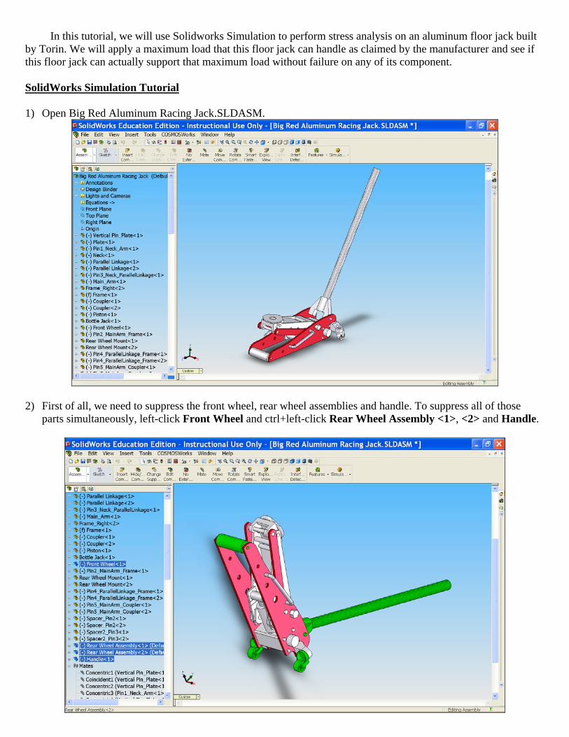
In this tutorial, we will use Solidworks Simulation to perform stress analysis on an aluminum floor jack built by Torin. We will apply a maximum load that this floor jack can handle as claimed by the manufacturer and see if this floor jack can actually support that maximum load without failure on any of its component. SolidWorks Simulation Tutorial 1) Open Big Red Aluminum Racing Jack.SLDASM.
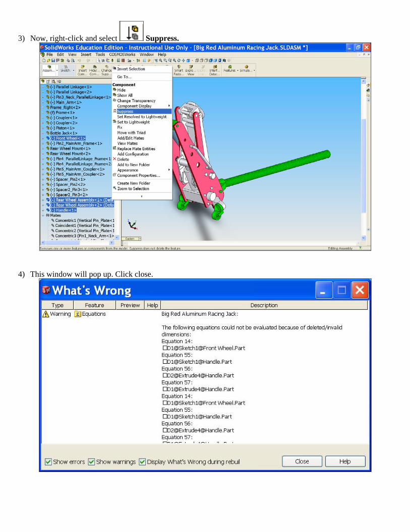
2) First of all, we need to suppress the front wheel, rear wheel assemblies and handle. To suppress all of those
parts simultaneously, left-click Front Wheel and ctrl+left-click Rear Wheel Assembly <1>, <2> and Handle.
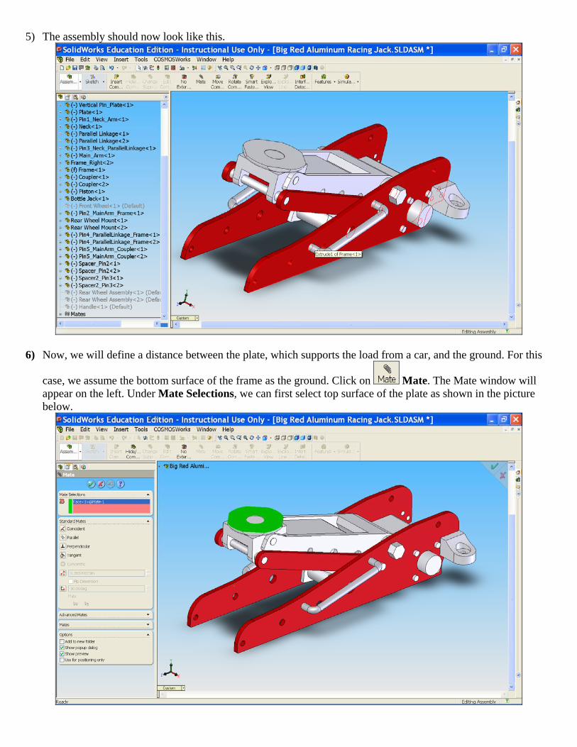
3) Now, right-click and select Suppress.
4) This window will pop up. Click close.
5) The assembly should now look like this.
6) Now, we will define a distance between the plate, which supports the load from a car, and the ground. For this
case, we assume the bottom surface of the frame as the ground. Click on Mate. The Mate window will appear on the left. Under Mate Selections, we can first select top surface of the plate as shown in the picture below.
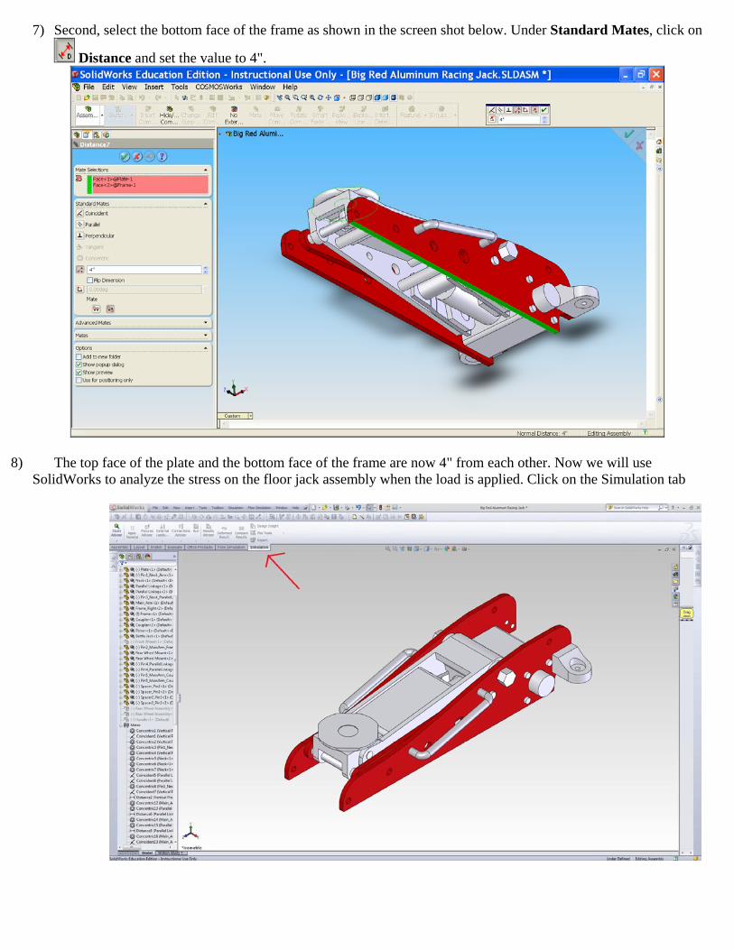
7) Second, select the bottom face of the frame as shown in the screen shot below. Under Standard Mates, click on
Distance and set the value to 4".
8) The top face of the plate and the bottom face of the frame are now 4" from each other. Now we will use SolidWorks to analyze the stress on the floor jack assembly when the load is applied. Click on the Simulation tab
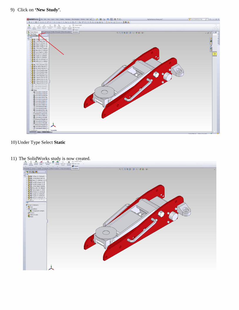
9) Click on ‘New Study’.
10) Under Type Select Static
11) The SolidWorks study is now created.
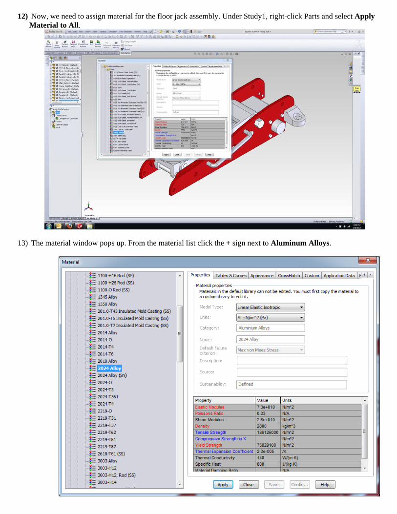
12) Now, we need to assign material for the floor jack assembly. Under Study1, right-click Parts and select Apply Material to All.
13) The material window pops up. From the material list click the + sign next to Aluminum Alloys.
14) Under Aluminium Alloys, select 2024 Alloy. Click Apply, then Close.
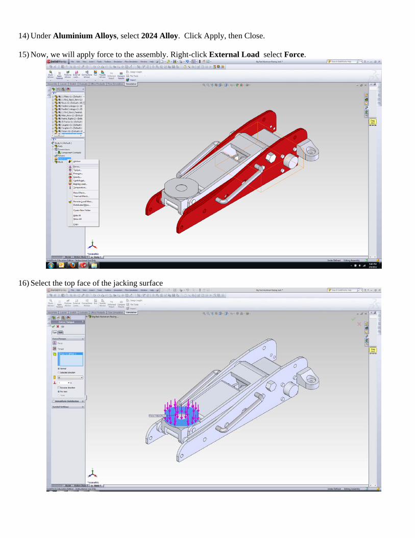
15) Now, we will apply force to the assembly. Right-click External Load select Force.
16) Select the top face of the jacking surface
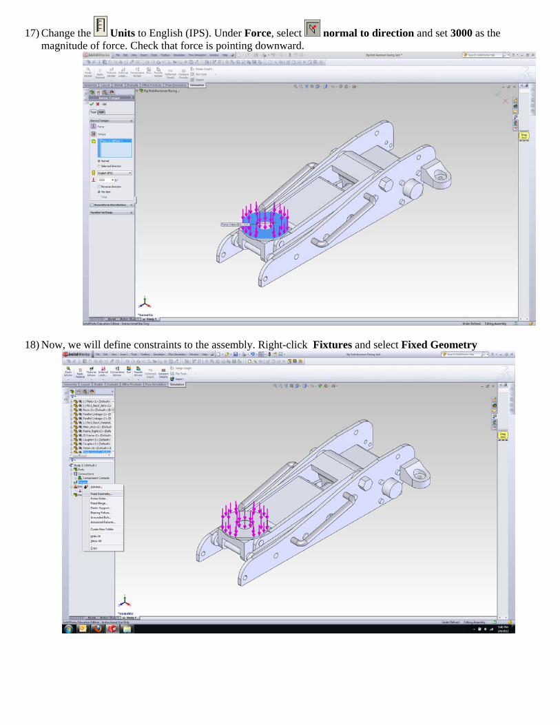
17) Change the Units to English (IPS). Under Force, select normal to direction and set 3000 as the magnitude of force. Check that force is pointing downward.
18) Now, we will define constraints to the assembly. Right-click Fixtures and select Fixed Geometry
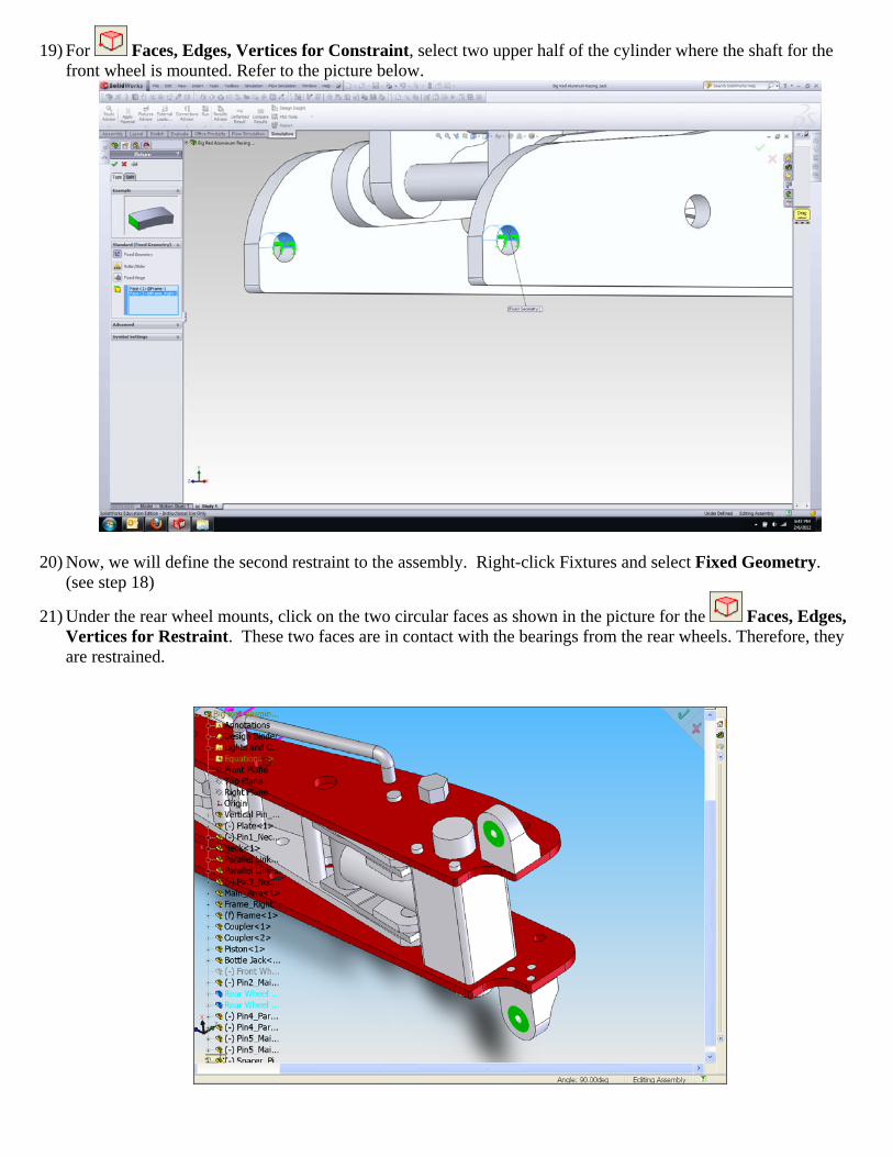
19) For Faces, Edges, Vertices for Constraint, select two upper half of the cylinder where the shaft for the front wheel is mounted. Refer to the picture below.
20) Now, we will define the second restraint to the assembly. Right-click Fixtures and select Fixed Geometry. (see step 18)
21) Under the rear wheel mounts, click on the two circular faces as shown in the picture for the Faces, Edges, Vertices for Restraint. These two faces are in contact with the bearings from the rear wheels. Therefore, they are restrained.
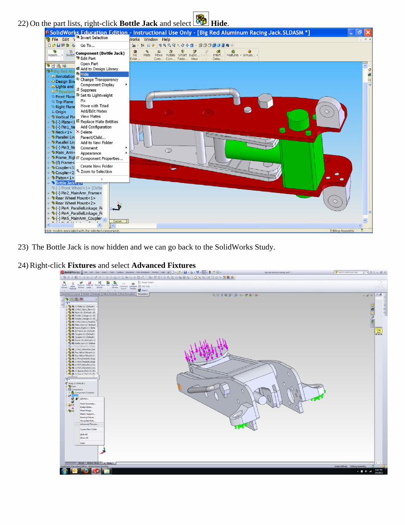
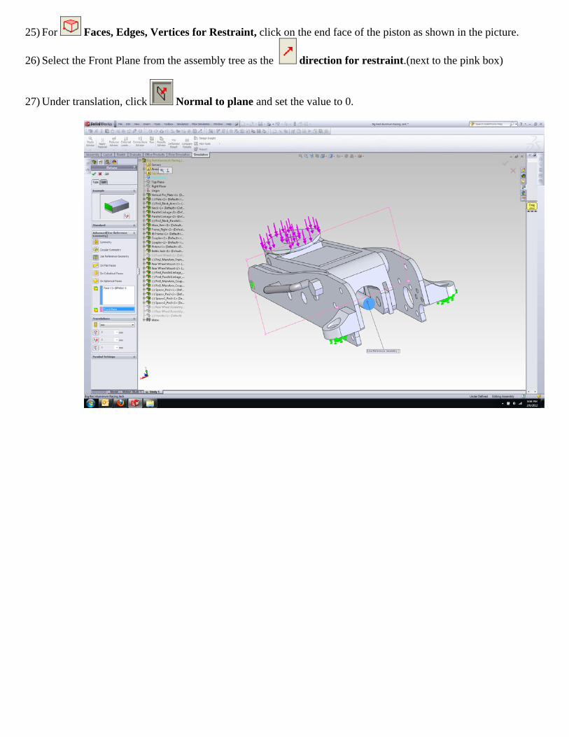
22) On the part lists, right-click Bottle Jack and select Hide.
23) The Bottle Jack is now hidden and we can go back to the SolidWorks Study.
24) Right-click Fixtures and select Advanced Fixtures
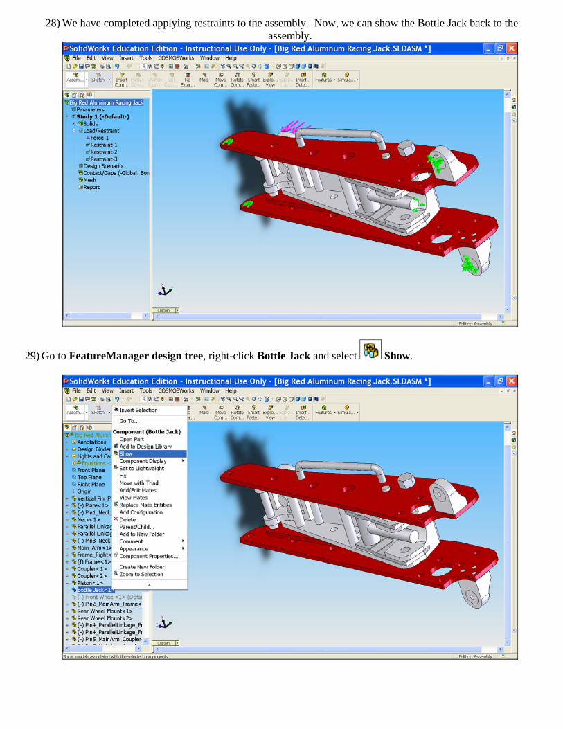
25) For Faces, Edges, Vertices for Restraint, click on the end face of the piston as shown in the picture.
26) Select the Front Plane from the assembly tree as the direction for restraint.(next to the pink box)
27) Under translation, click Normal to plane and set the value to 0.
28) We have completed applying restraints to the assembly. Now, we can show the Bottle Jack back to the assembly.
29) Go to FeatureManager design tree, right-click Bottle Jack and select Show.
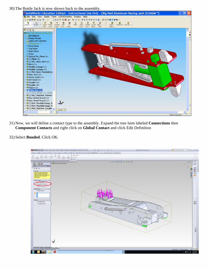
30) The Bottle Jack is now shown back to the assembly.
31) Now, we will define a contact type to the assembly. Expand the tree item labeled Connections then Component Contacts and right click on Global Contact and click Edit Definition
32) Select Bonded. Click OK.
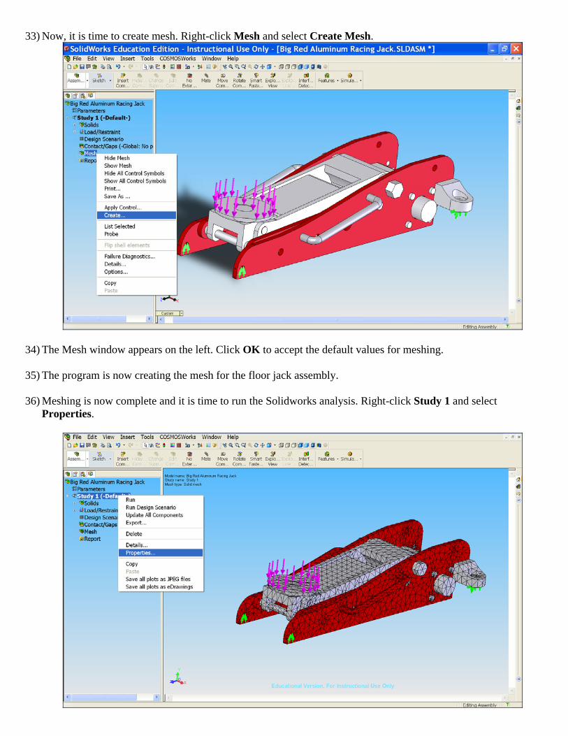
33) Now, it is time to create mesh. Right-click Mesh and select Create Mesh.
34) The Mesh window appears on the left. Click OK to accept the default values for meshing.
35) The program is now creating the mesh for the floor jack assembly.
36) Meshing is now complete and it is time to run the Solidworks analysis. Right-click Study 1 and select Properties.
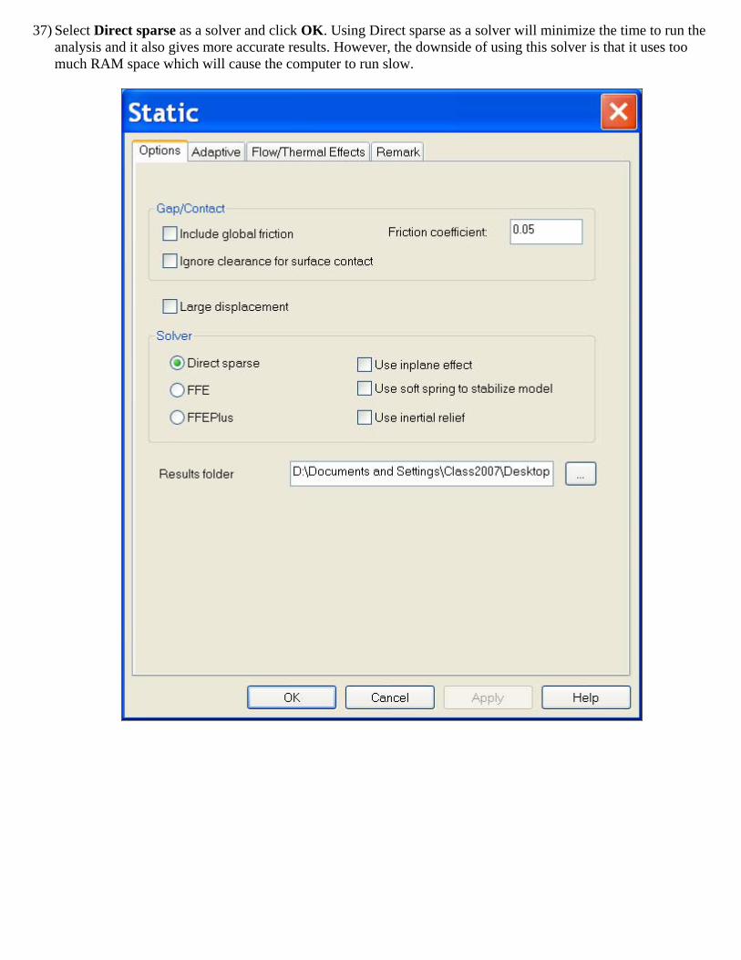
37) Select Direct sparse as a solver and click OK. Using Direct sparse as a solver will minimize the time to run the analysis and it also gives more accurate results. However, the downside of using this solver is that it uses too much RAM space which will cause the computer to run slow.
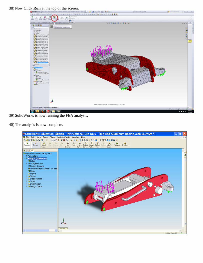
38) Now Click Run at the top of the screen.
39) SolidWorks is now running the FEA analysis.
40) The analysis is now complete.
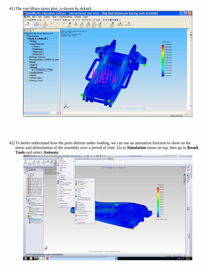
41) The von Mises stress plot, is shown by default
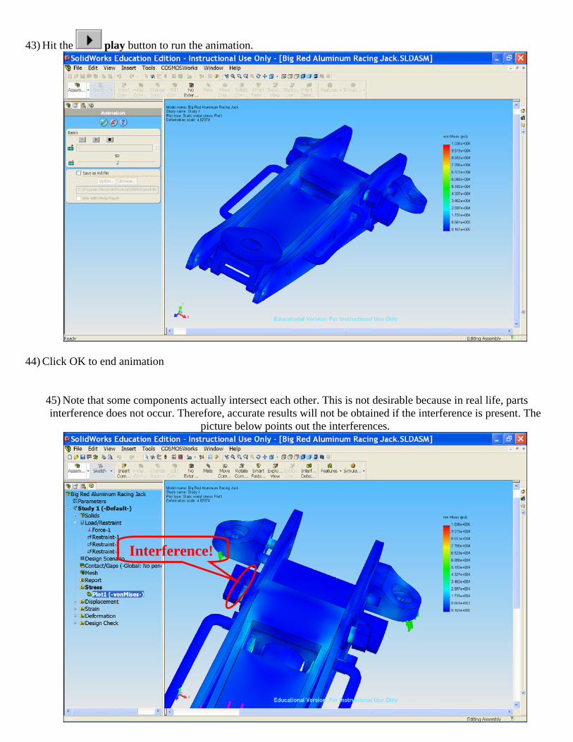
42) To better understand how the parts deform under loading, we can use an animation function to show us the stress and deformation of the assembly over a period of time. Go to Simulation menu on top, then go to Result Tools and select Animate.
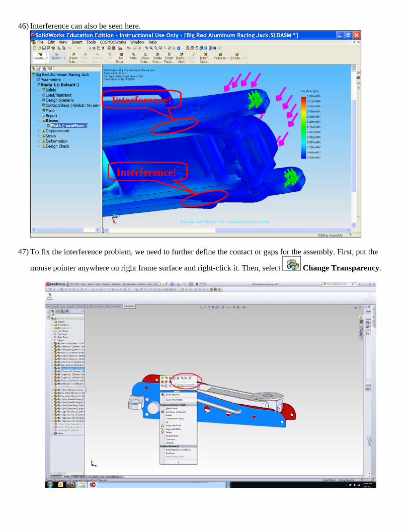
43) Hit the play button to run the animation.
44) Click OK to end animation
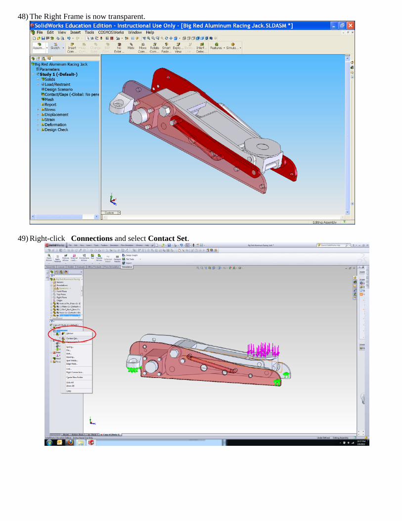
45) Note that some components actually intersect each other. This is not desirable because in real life, parts interference does not occur. Therefore, accurate results will not be obtained if the interference is present. The
picture below points out the interferences.
Interference!
46) Interference can also be seen here.
47) To fix the interference problem, we need to further define the contact or gaps for the assembly. First, put the
mouse pointer anywhere on right frame surface and right-click it. Then, select Change Transparency.
Interference!
Interference!
48) The Right Frame is now transparent.
49) Right-click Connections and select Contact Set.
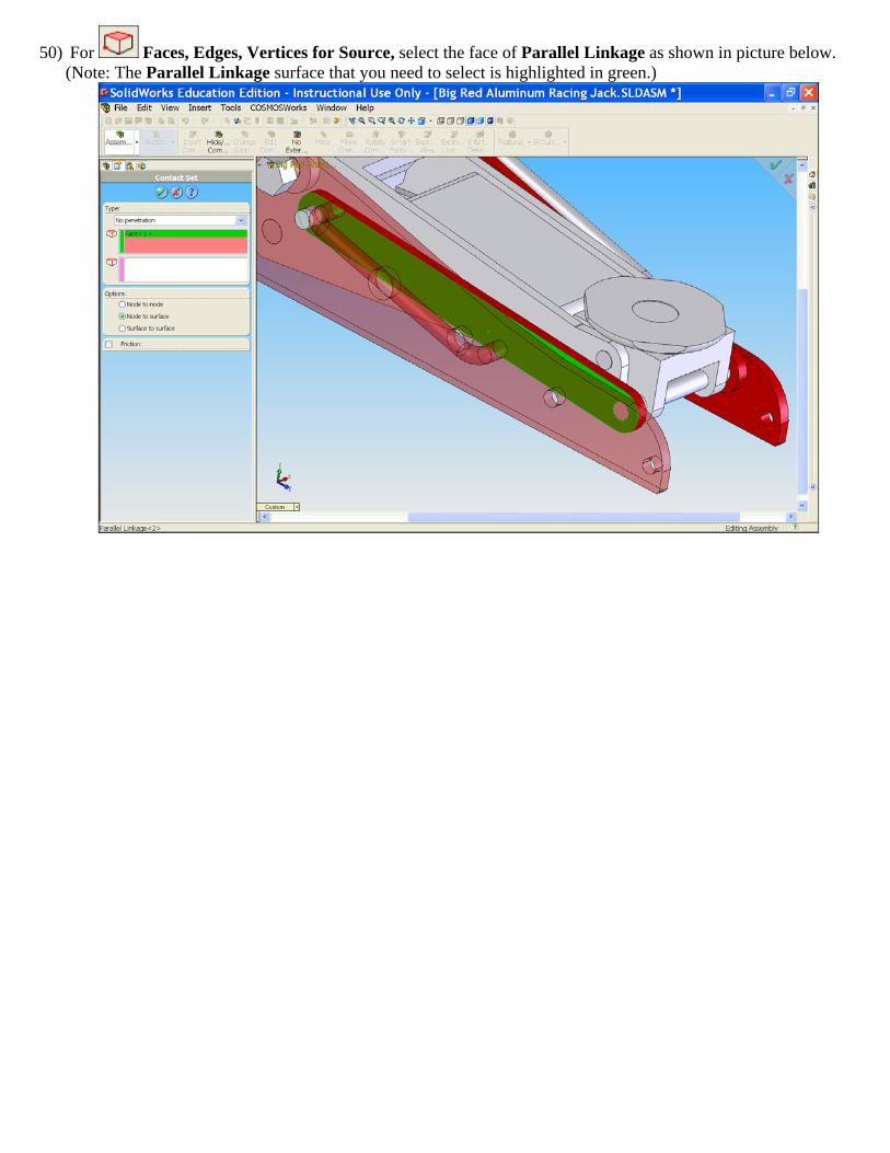
50) For Faces, Edges, Vertices for Source, select the face of Parallel Linkage as shown in picture below. (Note: The Parallel Linkage surface that you need to select is highlighted in green.)
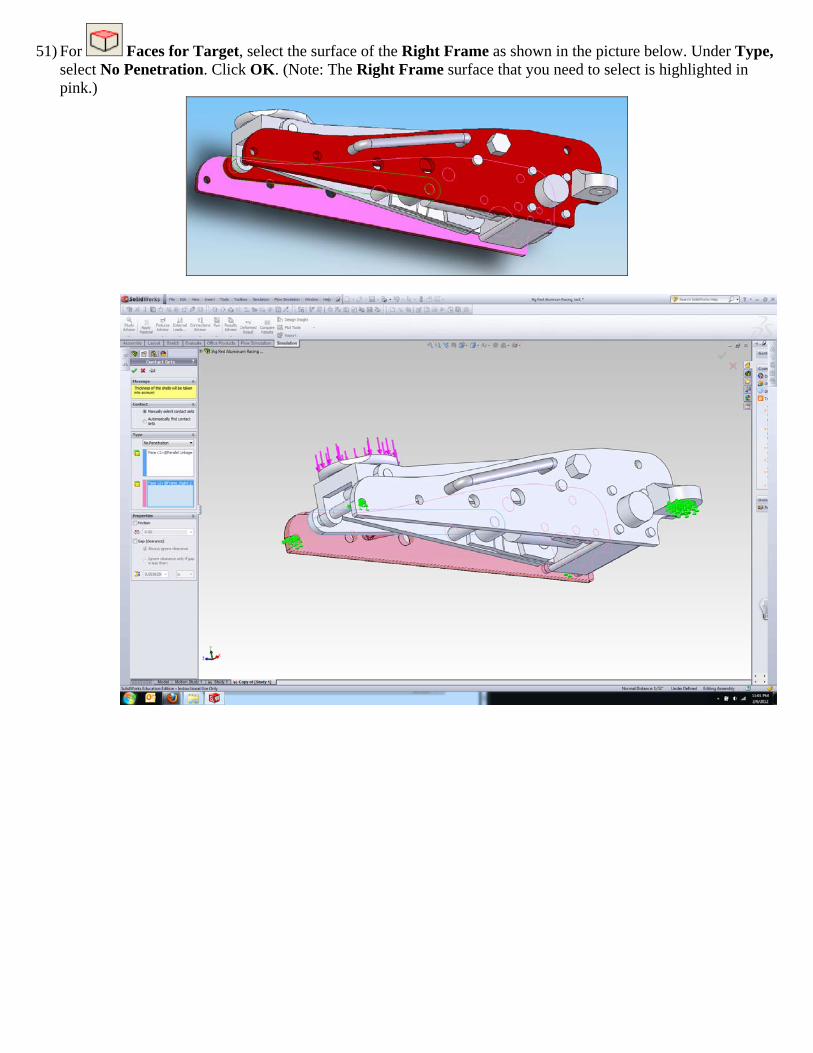
51) For Faces for Target, select the surface of the Right Frame as shown in the picture below. Under Type, select No Penetration. Click OK. (Note: The Right Frame surface that you need to select is highlighted in pink.)
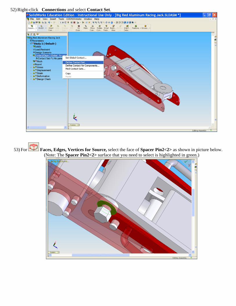
52) Right-click Connections and select Contact Set.
53) For Faces, Edges, Vertices for Source, select the face of Spacer Pin2<2> as shown in picture below. (Note: The Spacer Pin2<2> surface that you need to select is highlighted in green.)
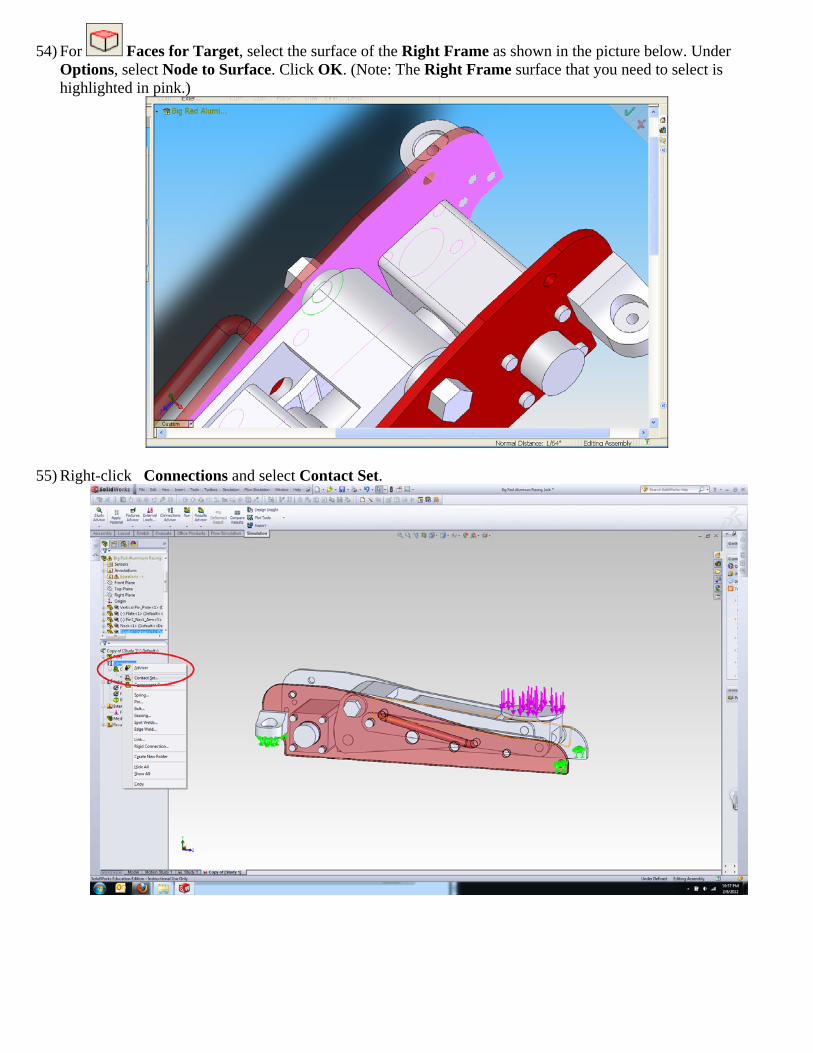
54) For Faces for Target, select the surface of the Right Frame as shown in the picture below. Under Options, select Node to Surface. Click OK. (Note: The Right Frame surface that you need to select is highlighted in pink.)
55) Right-click Connections and select Contact Set.
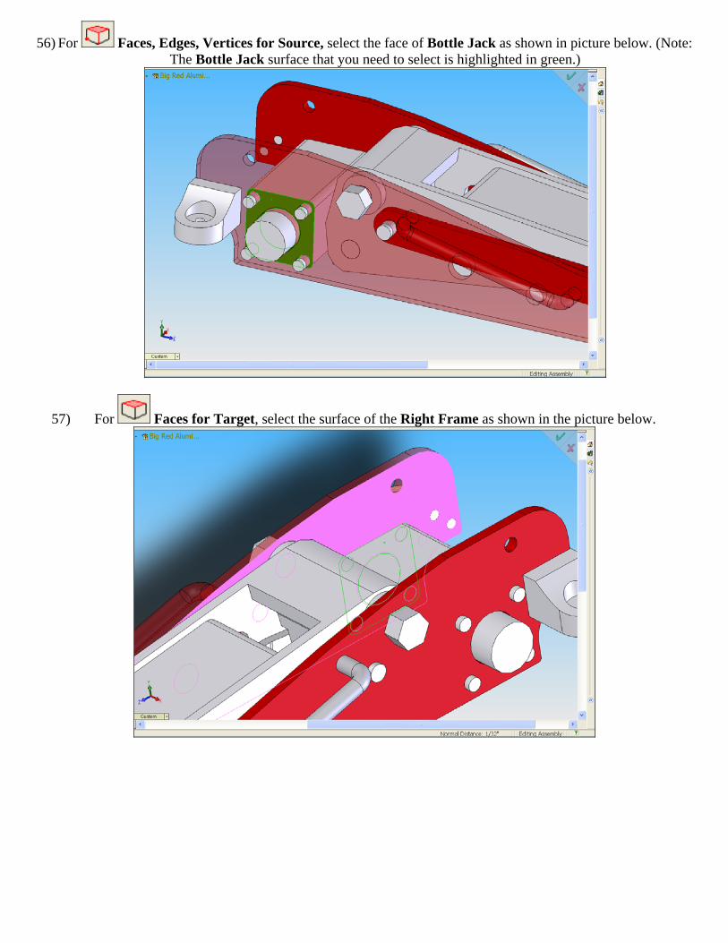
56) For Faces, Edges, Vertices for Source, select the face of Bottle Jack as shown in picture below. (Note: The Bottle Jack surface that you need to select is highlighted in green.)
57) For Faces for Target, select the surface of the Right Frame as shown in the picture below.
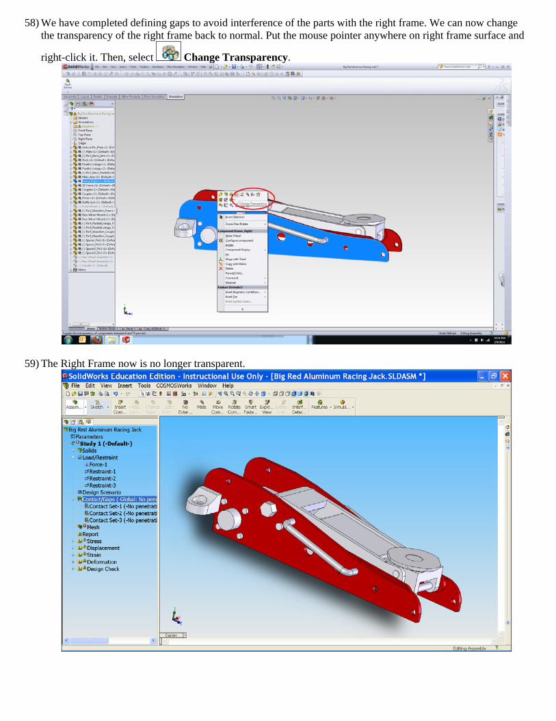
58) We have completed defining gaps to avoid interference of the parts with the right frame. We can now change the transparency of the right frame back to normal. Put the mouse pointer anywhere on right frame surface and
right-click it. Then, select Change Transparency.
59) The Right Frame now is no longer transparent.
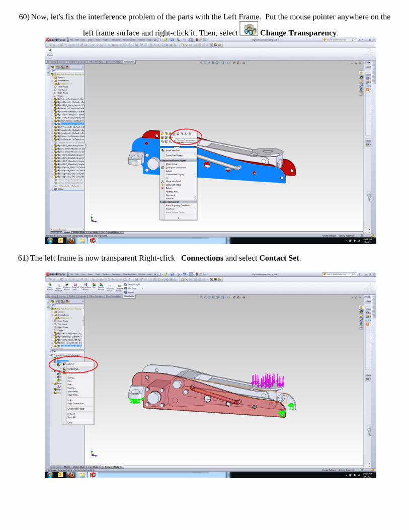
60) Now, let's fix the interference problem of the parts with the Left Frame. Put the mouse pointer anywhere on the
left frame surface and right-click it. Then, select Change Transparency.
61) The left frame is now transparent Right-click Connections and select Contact Set.
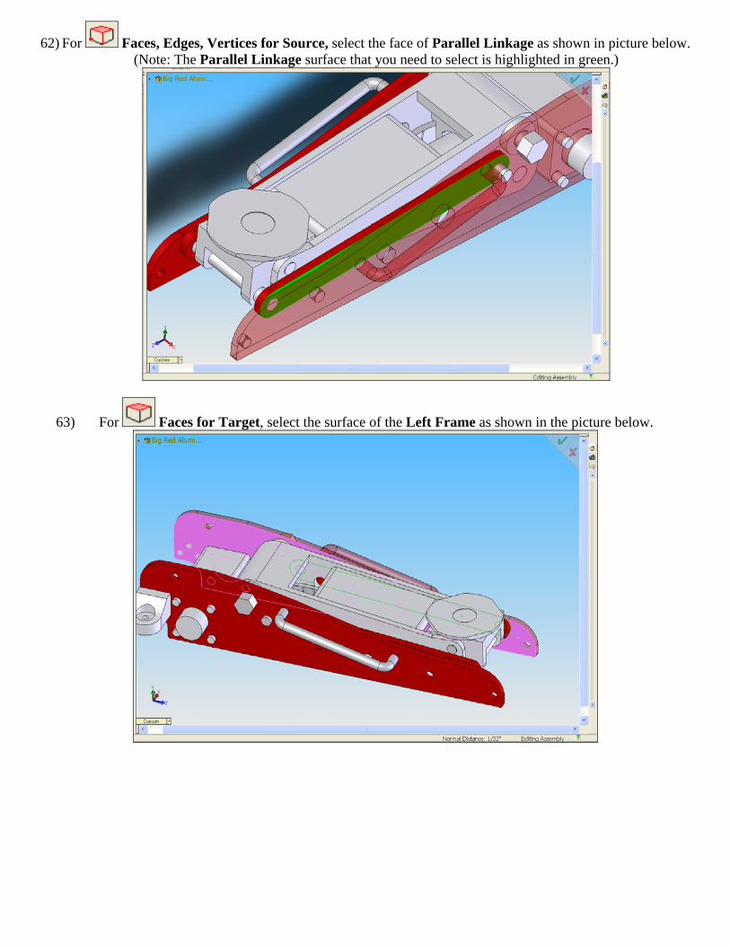
62) For Faces, Edges, Vertices for Source, select the face of Parallel Linkage as shown in picture below. (Note: The Parallel Linkage surface that you need to select is highlighted in green.)
63) For Faces for Target, select the surface of the Left Frame as shown in the picture below.
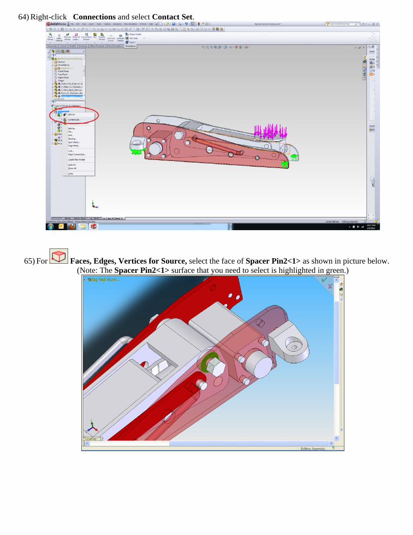
64) Right-click Connections and select Contact Set.
65) For Faces, Edges, Vertices for Source, select the face of Spacer Pin2<1> as shown in picture below. (Note: The Spacer Pin2<1> surface that you need to select is highlighted in green.)
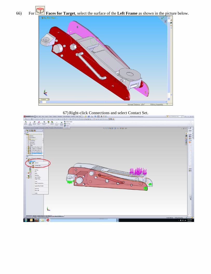
66) For Faces for Target, select the surface of the Left Frame as shown in the picture below.
67) Right-click Connections and select Contact Set.
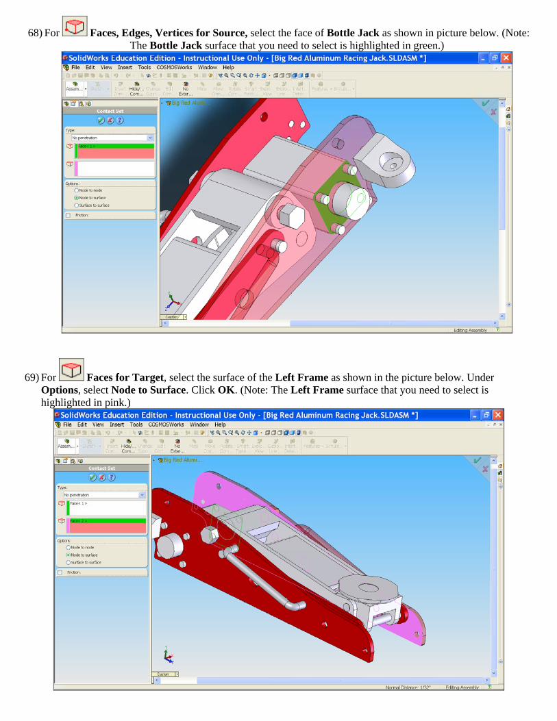
68) For Faces, Edges, Vertices for Source, select the face of Bottle Jack as shown in picture below. (Note: The Bottle Jack surface that you need to select is highlighted in green.)
69) For Faces for Target, select the surface of the Left Frame as shown in the picture below. Under Options, select Node to Surface. Click OK. (Note: The Left Frame surface that you need to select is highlighted in pink.)
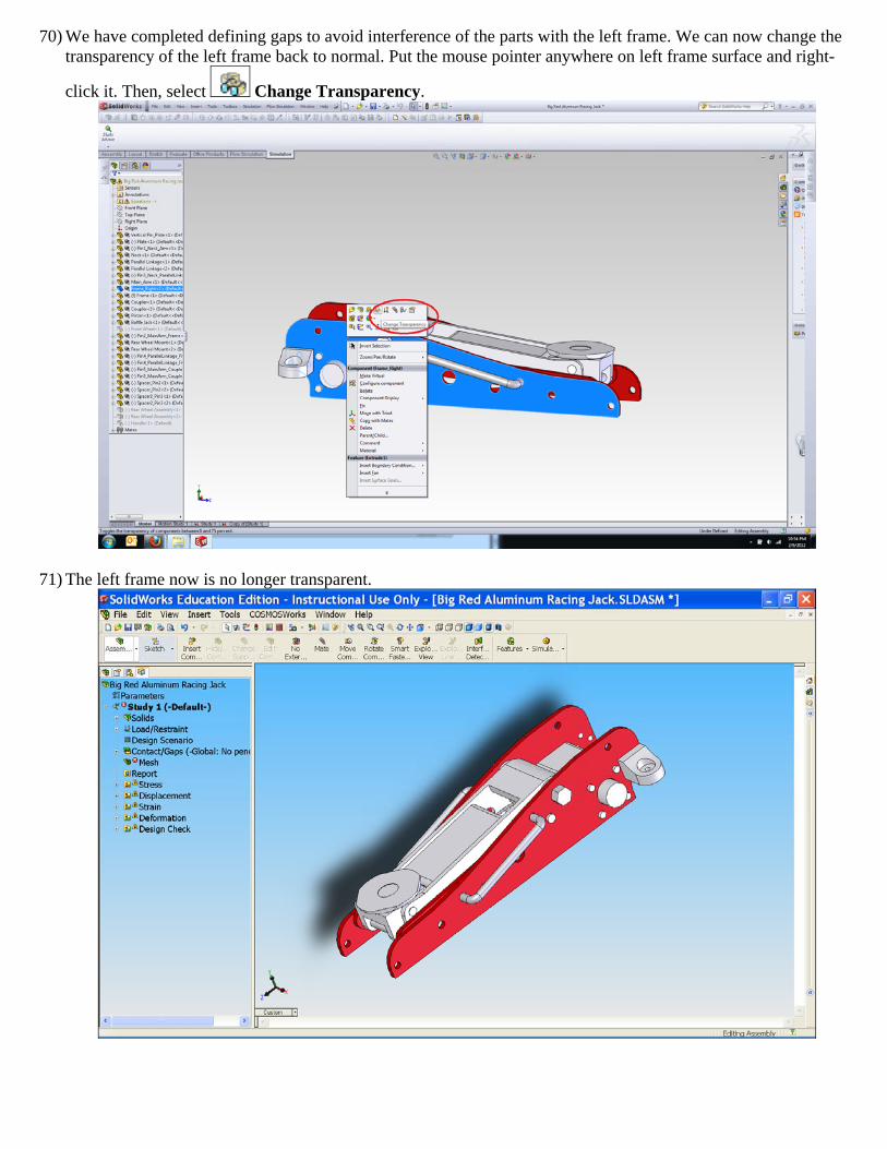
70) We have completed defining gaps to avoid interference of the parts with the left frame. We can now change the transparency of the left frame back to normal. Put the mouse pointer anywhere on left frame surface and right-
click it. Then, select Change Transparency.
71) The left frame now is no longer transparent.
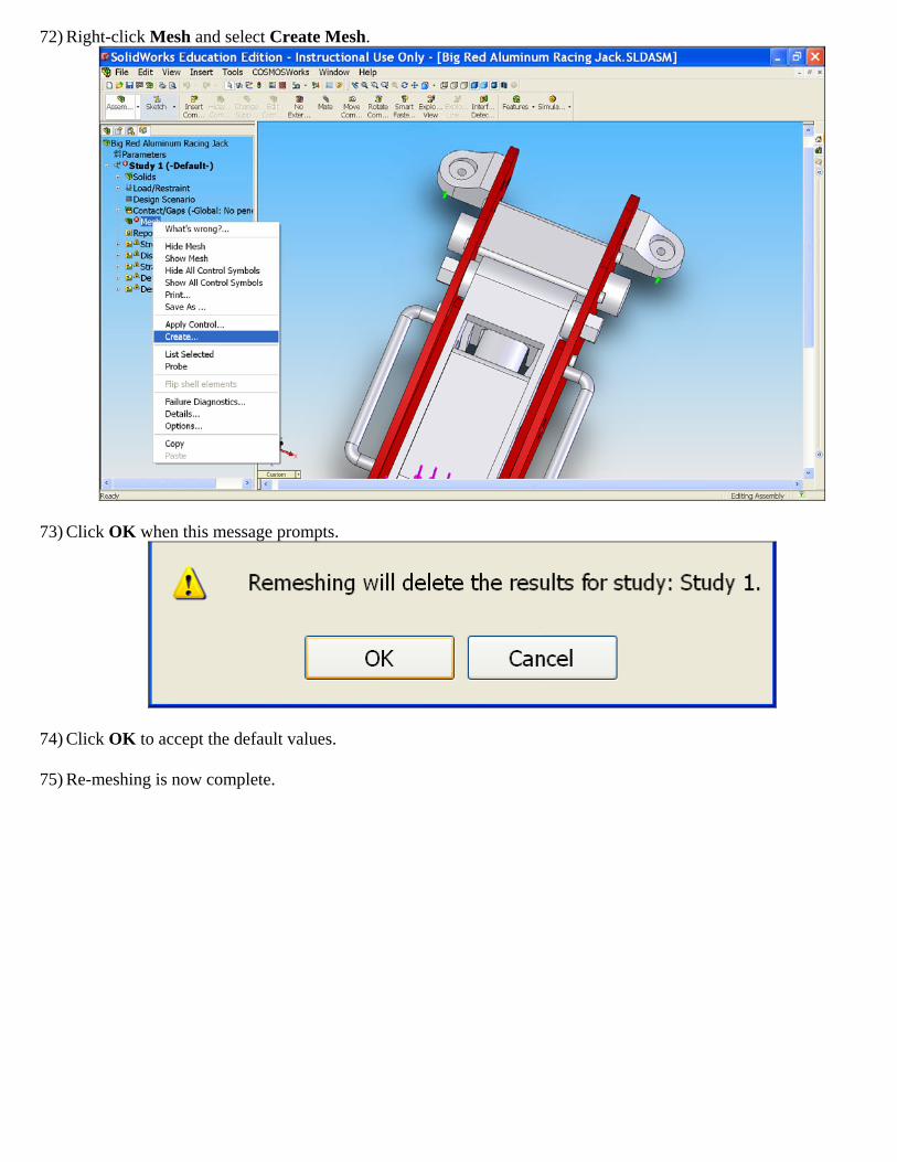
72) Right-click Mesh and select Create Mesh.
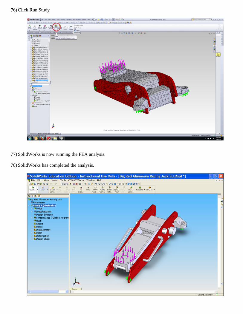
73) Click OK when this message prompts.
74) Click OK to accept the default values.
75) Re-meshing is now complete.
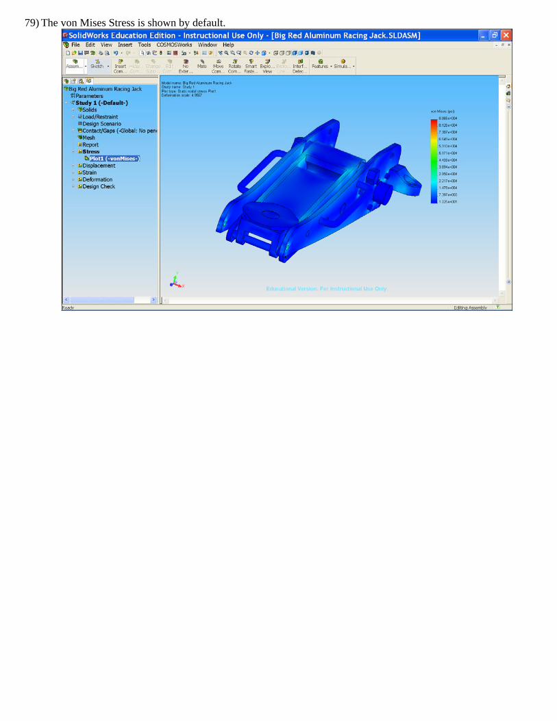
76) Click Run Study
77) SolidWorks is now running the FEA analysis.
78) SolidWorks has completed the analysis.
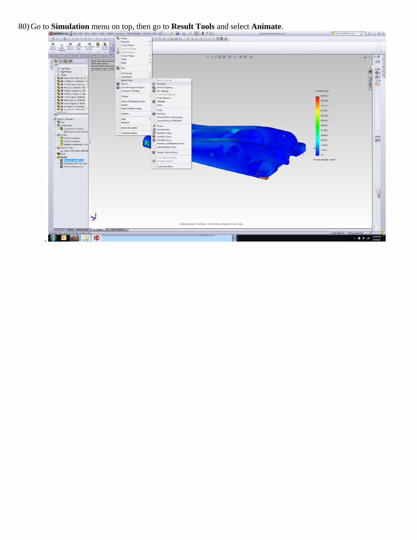
79) The von Mises Stress is shown by default.
80) Go to Simulation menu on top, then go to Result Tools and select Animate.
.
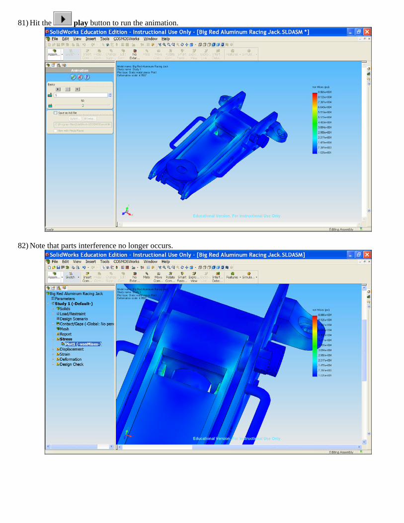
81) Hit the play button to run the animation.
82) Note that parts interference no longer occurs.
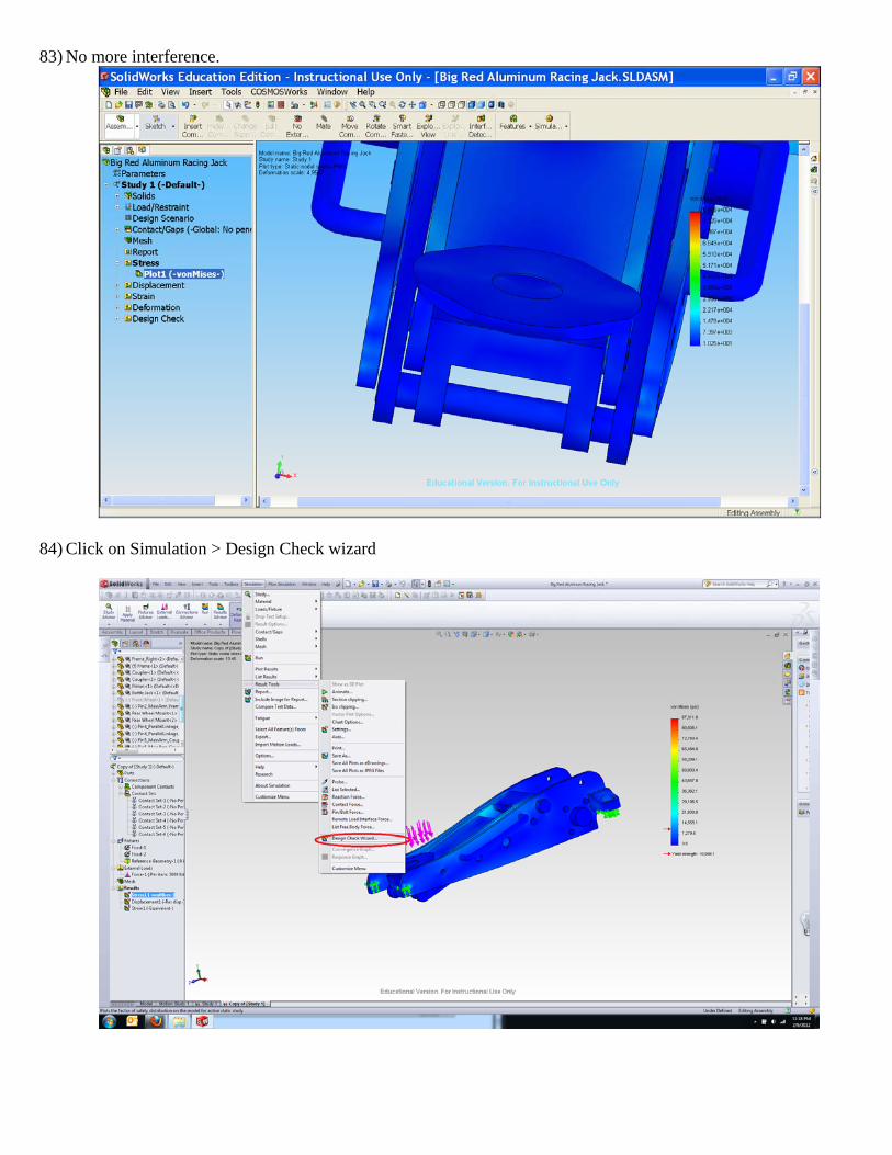
83) No more interference.
84) Click on Simulation > Design Check wizard
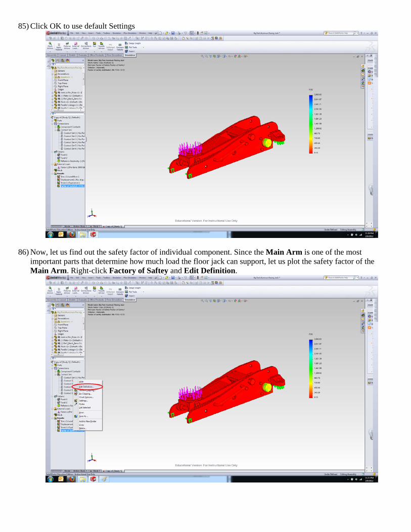
85) Click OK to use default Settings
86) Now, let us find out the safety factor of individual component. Since the Main Arm is one of the most important parts that determine how much load the floor jack can support, let us plot the safety factor of the Main Arm. Right-click Factory of Saftey and Edit Definition.
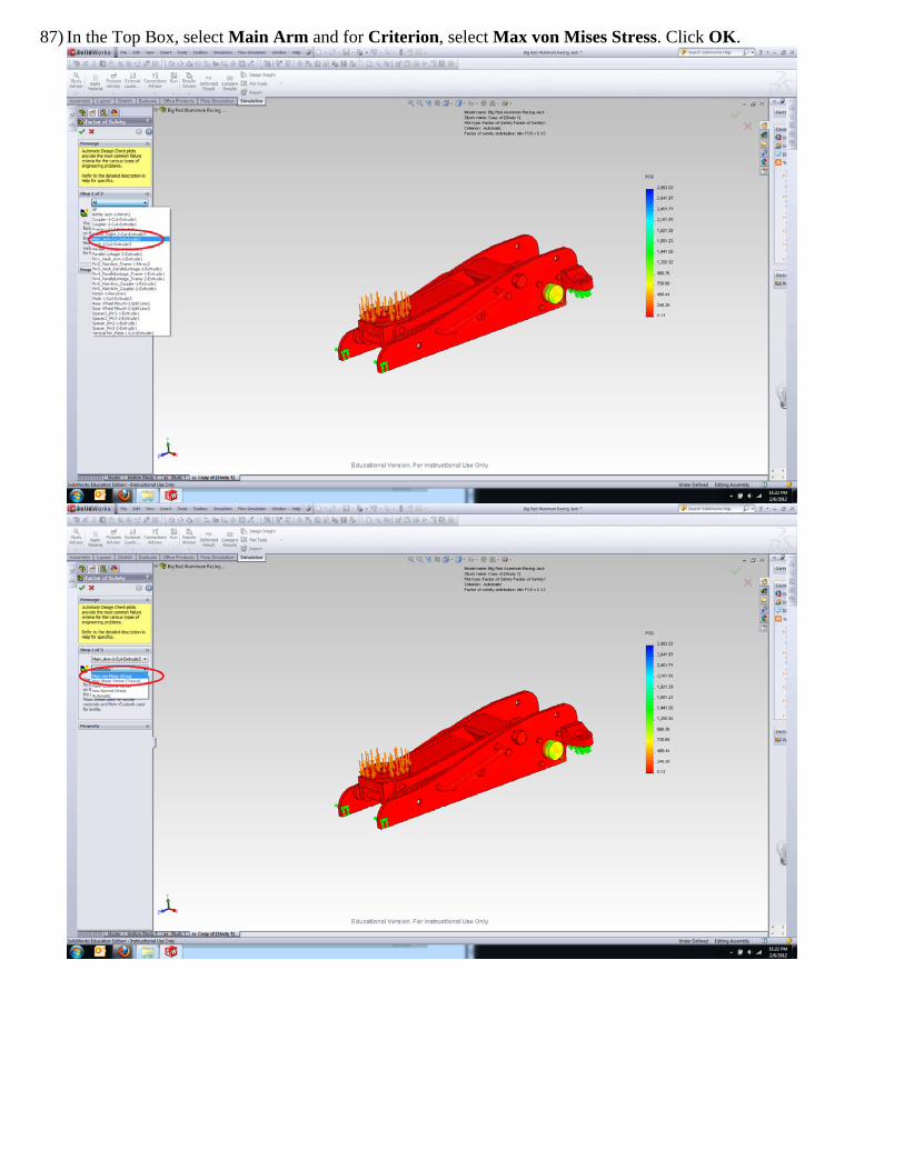
87) In the Top Box, select Main Arm and for Criterion, select Max von Mises Stress. Click OK.
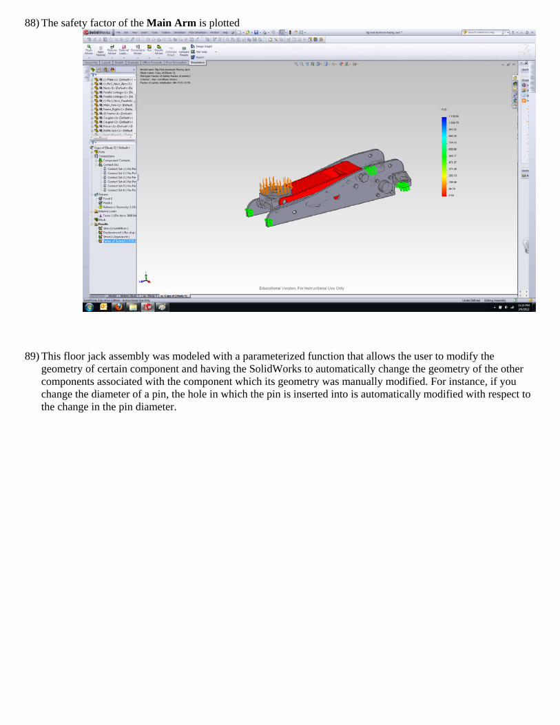
88) The safety factor of the Main Arm is plotted
89) This floor jack assembly was modeled with a parameterized function that allows the user to modify the geometry of certain component and having the SolidWorks to automatically change the geometry of the other components associated with the component which its geometry was manually modified. For instance, if you change the diameter of a pin, the hole in which the pin is inserted into is automatically modified with respect to the change in the pin diameter.
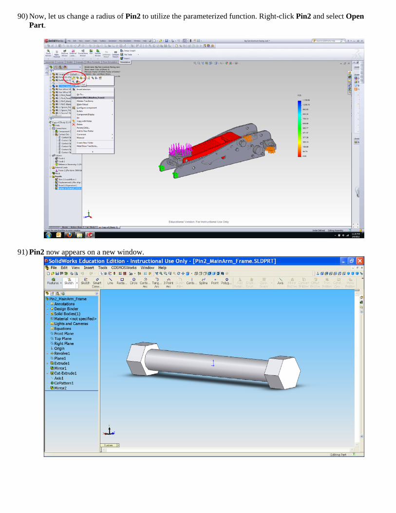
90) Now, let us change a radius of Pin2 to utilize the parameterized function. Right-click Pin2 and select Open Part.
91) Pin2 now appears on a new window.
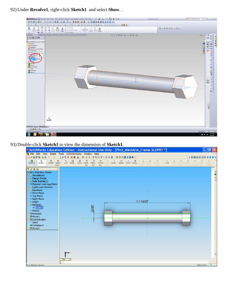
92) Under Revolve1, right-click Sketch1 and select Show. .
93) Double-click Sketch1 to view the dimension of Sketch1.
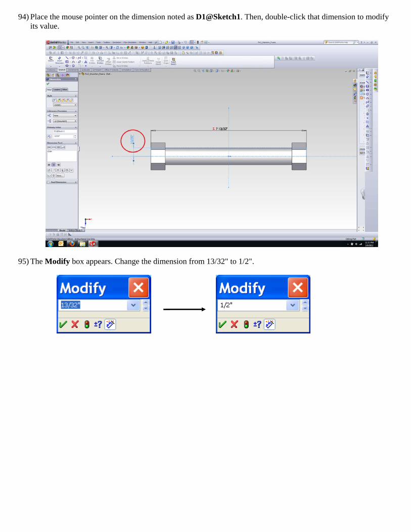
94) Place the mouse pointer on the dimension noted as D1@Sketch1. Then, double-click that dimension to modify its value.
95) The Modify box appears. Change the dimension from 13/32" to 1/2".
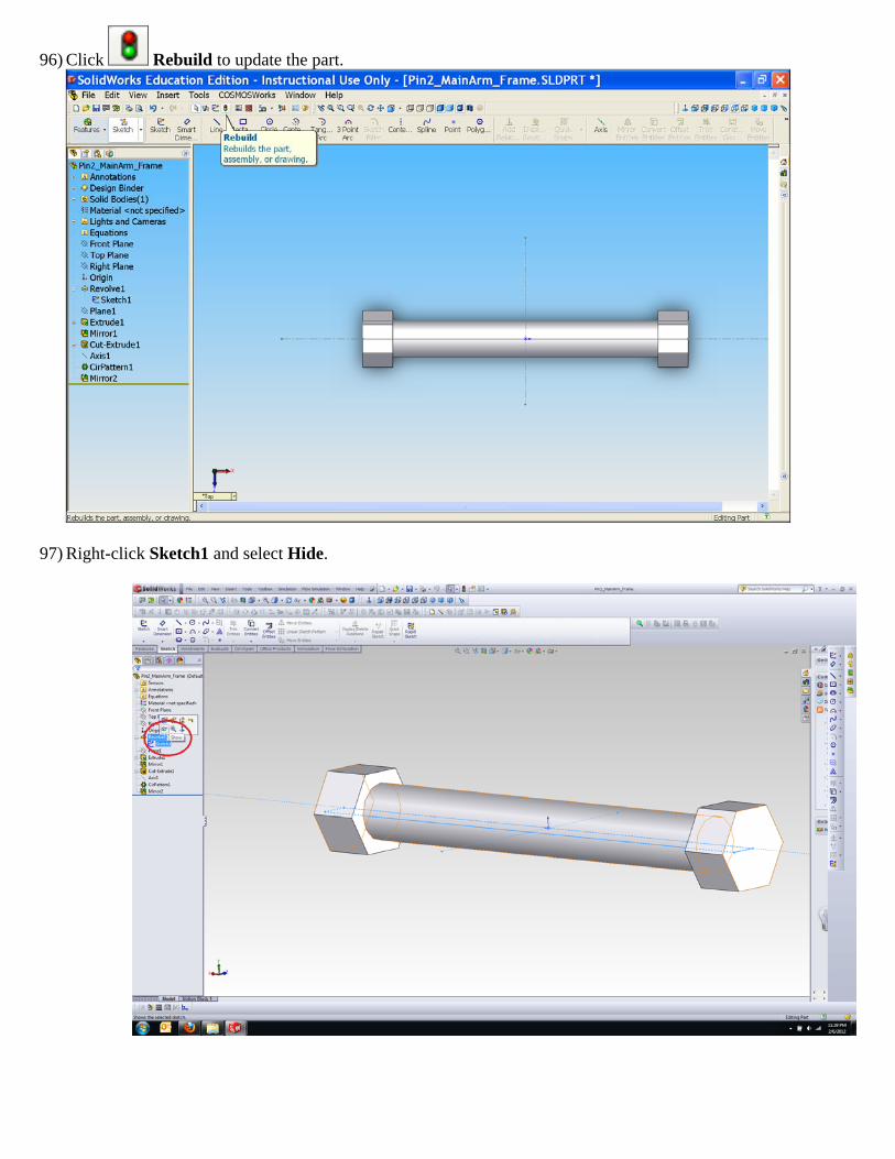
96) Click Rebuild to update the part.
97) Right-click Sketch1 and select Hide.
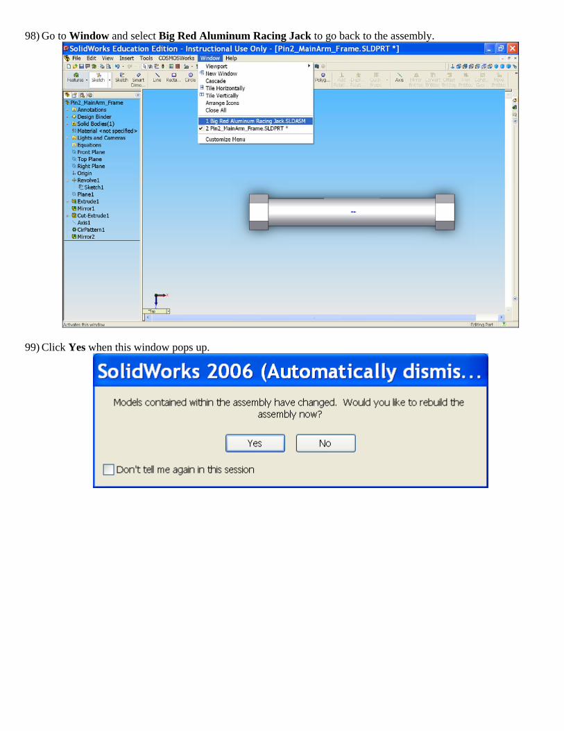
98) Go to Window and select Big Red Aluminum Racing Jack to go back to the assembly.
99) Click Yes when this window pops up.
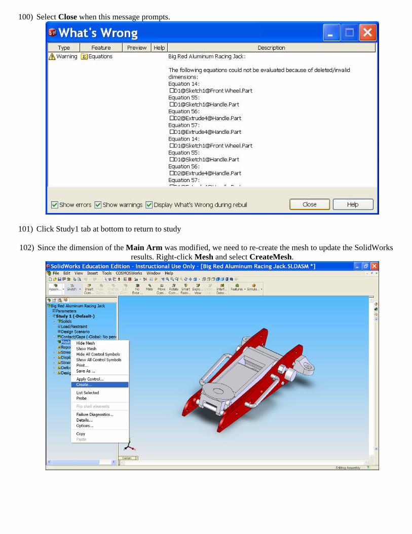
100) Select Close when this message prompts.
101) Click Study1 tab at bottom to return to study
102) Since the dimension of the Main Arm was modified, we need to re-create the mesh to update the SolidWorks results. Right-click Mesh and select CreateMesh.
103) Click OK to proceed with the default mesh parameters values.
104) Run the study
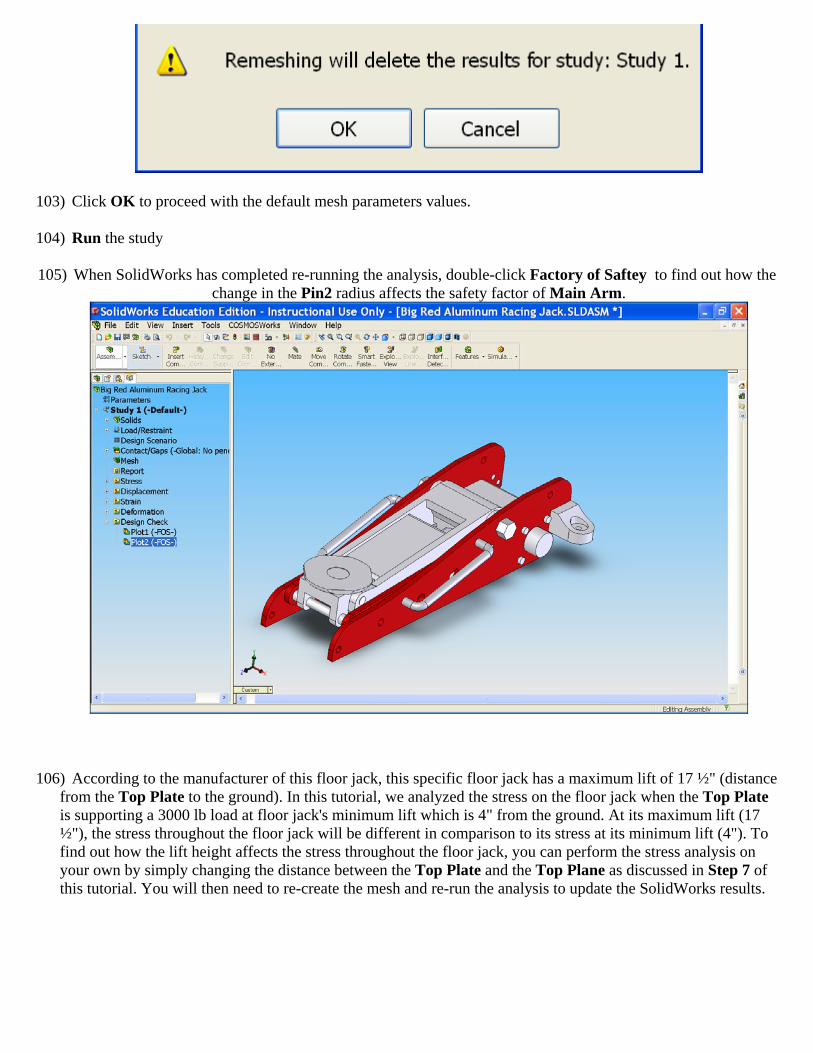
105) When SolidWorks has completed re-running the analysis, double-click Factory of Saftey to find out how the change in the Pin2 radius affects the safety factor of Main Arm.
106) According to the manufacturer of this floor jack, this specific floor jack has a maximum lift of 17 ½" (distance from the Top Plate to the ground). In this tutorial, we analyzed the stress on the floor jack when the Top Plate is supporting a 3000 lb load at floor jack's minimum lift which is 4" from the ground. At its maximum lift (17 ½"), the stress throughout the floor jack will be different in comparison to its stress at its minimum lift (4"). To find out how the lift height affects the stress throughout the floor jack, you can perform the stress analysis on your own by simply changing the distance between the Top Plate and the Top Plane as discussed in Step 7 of this tutorial. You will then need to re-create the mesh and re-run the analysis to update the SolidWorks results.