solidification || application of the separation theory
TRANSCRIPT

3 Application of the Separation Theory
So far I have discussed my motives in beginning research into the solidification of metals, my advocacy of the crystal separation theory, and control of cast structures based on the separation theory. In brief, I have discussed the exceedingly simple principle that in order to obtain equiaxed crystals, one should ascertain where they form and then cause many crystals to form there and separate and precipitate. If one wants columnar crystals, one should ensure that the crystals do not separate from where they have formed.
From here on I want to apply this crystal separation theory to the issue of the solidification of practical alloys, which is a subject that conventionally has been regarded as relatively difficult to explain.
Before that, however, I feel that the separation theory requires some additional explanation.
I often hear people say that "Crystal separaton certainly does exist, and is a powerful mechanism producing free crystals, but it is hardly conceivable that free crystals can only be produced through crystal separation."
The metal solidification mechanism I have discussed so far only covers the case in which molten metal which is completely melted is merely poured into a mould and solidified. It is my contention that "The equiaxed crystals formed in this case are produced by crystal separation, and cannot be logically explained by conventional theories."
As I shall state later on when discussing spherical graphite cast iron, if special measures are artificially devised and crystal separation from the mould wall is prevented completely and a local undercooled zone is created within the liquid, then naturally free crystals can nucleate there, and I have not the slightest intention of denying this.
What I would like to particularly emphasize here is the fact that just because free crystals formed in the liquid when such special steps were taken, it must not be thought that this mechanism can produce equiaxed crystals in normal casting. Let me first add this by way of caution.
Based on the separation theory, I have attempted to elucidate various issues which were difficult to understand in the past. I have learnt that there is a great number of questions that can be explained logically by the separation theory.
A. Ohno, Solidification© Springer-Verlag Berlin Heidelberg 1987

84 3 Application of the Separation Theory
Here I would like to select some of these issues that I feel may be of interest to the reader.
One issue is the creation of inverse chill in cast iron. When cast iron molten metal is quenched it turns into white cast iron, and when it is gradually cooled it turns into grey cast iron. However, ingots are often obtained in which the surface layer of the casting in contact with the mould is grey cast iron, and the inside which should have been gradually cooled consists of white cast iron, and I know many firms are having difficulty preventing this phenomenon.
So as to solve this question, rather than directly going to the solidification of cast iron, I firstly examined the solidification process of other eutectic system alloys whose eutectic system phase diagram is the same as that of cast iron in order to determine whether or not some solidification phenomenon common to eutectic system alloys exists.
So as to attack the keep of the castle, I adopted the method of first filling in the outer moats one by one.
Let us now discuss the solidification of eutectic system alloys, and eventually link it to the creation of inverse chill in cast iron.
3.1 Formation of the Macro Structure of Eutectic Alloys
3.1.1 Primary Crystal Distribution and Equiaxed Eutectic Grains
I would like to advise the reader that when looking at the solidification structure of eutectic alloys, instead of immediately using a microscope to look at the micro structure of the fine eutectics, he should firstly observe the alloy structure in macroscopic terms.
I say this because when the specific gravity of the primary crystals differs from that of the molten metal, the distribution of primary crystals differs greatly from place to place, and in some cases the configuration of the eutectic grains is influenced by this.
Even more important is the fact that the mechanical properties of eutectic alloys at high temperatures are affected by the grain boundaries rather than by the internal structure of the eutectics existing there. This is because the last place to solidify during the solidification of eutectic alloys is the boundaries of the eutectic grains.
Conversely, when eutectic alloys are heated it is the eutectic grain boundaries that begin to melt first. Consequently, finding an effective means of controlling the configuration and size of eutectic grains is extremely vital to improving the mechanical properties of eutectic alloys, and particularly their properties at high temperatures.
A look at the macro structure of eutectic alloys shows that it closely resembles that of isomorphous alloys. Classified by shape, eutectic grains

3.1 Formation of the Macro Structure of Eutectic Alloys 85
fall into the two groups of columnar eutectic grains and equiaxed eutectic grains.
If we ignore the existence of primary crystals, the macro structures of eutectic alloys can be classified into ones consisting entirely of columnar eutectic grains, ones with an equiaxedeutectic grain zone surrounded by a columnar eutectic grain zone, and ones consisting entirely of an equiaxed eutectic grain zone, as shown in Fig. 3.1.
(a) (b) (el
Fig. 3.1 Macro structure of the eutectic matrix of eutectic system alloys
In order to clarify the process by which such eutectic grain structures are created, I observed the cast macro structure of numerous eutectic alloys such as AI-Cu; AI-Si, AI-Ni, AI-Zn and Sn-Bi. I learnt that they have a common feature.
126 selected hypo-eutectic and hyper-eutectic alloys whose composition is extremely close to the eutectic composition of these alloy systems, and cast them in an iron mould with an inner diameter of 35 mm and a depth of 100 mm. A tendency was observed in the macro structure of the ingots for the primary crystals always to be unevenly distributed in the center region of the ingots.
Depending on the alloy system, the primary crystals were distributed unevenly in the upper or lower part of the ingot. A common feature of all the alloy systems, however, was the fact that the primary crystals were distributed unevenly in the center, rather than in the outer region of the ingots.
In this experiment particular care was taken over the selection of the alloy compositions. I chose compositions that resemble the eutectic compositions as closely as possible. This was because as the composition comes to resemble the eutectic composition less and less, the amount of primary crystals increases and they disperse in the outer region of the ingot, an if the amount increases further, the primary crystals form a stable solid shell, so it is not possible to apprehend clearly this behavior of free crystals composed of primary crystals.
In actual fact, when I reported on these research results at the Conference on the Solidification of Metals held in Sheffield in England in 1977, Dr. J. Spittle27 of the University of Cardiff said: "We have observed the

86 3 Application of the Separation Theory
structure of numerous eutectic alloys, but have found no tendency for primary crystals to gather in the middle of the ingot. Most likely they nucleate within the undercooled molten metal and are distributed uniformly."
In order to ascertain the behavior of the primary crystals of eutectic alloys during solidification, their amount must be kept to the absolute minimum or else one loses track of what experiment is being performed.
Two types of eutectic grains that form the matrix in the solid structure of eutectic alloys were observed - that in which columnar eutectic grains grew from the mould wall without relation to the primary crystals, as in Fig.3.2(a), and that in which a columnar eutectic grain zone exists in the outer region surrounding an equiaxed eutectic grain zone in the center, as in Fig.3.2(b).
( a) (b)
Fig. 3.2 Macro structure of alloys close to the eutectic composition. (a) Primary crystals are non-leading phase; (b) Primary crystals are leading phase
As a typical example, let me introduce the macro and micro structures of AI-Cu alloy ingots.
First look at the hypo-eutectic alloy AI-32 % Cu in Fig. 3.3. On the left is the macro structure of the ingot profile, and on the right is the micro structure.
As this reveals, the matrix consists of columnar eutectic grains. What looks like white spots are the a Al primary crystals. This is even more clear in the photo on the right. There are no primary crystals in the outer region of the ingot, and they are distributed unevenly in the center, being dispersed without any relation to the columnar eutectic grains.
By contrast, in the hyper-eutectic alloy composed of AI-34% Cu, a columnar eutectic grain zone existed in the outer region of the ingot and surrounded an equiaxed eutectic grain zone in the center, as shown in Fig. 3.4. As the photos of the micro structure reveal, no primary crystal CuA12, which is known as a eutectic leading phase, was observed in the columnar eutectic grain zone in the outer region of the ingot. However, it was observed that the primary crystals CuAl2 always exist in the center of the equiaxed eutectic grains.
Figure 3.5 shows the structes of the center portion of ingots made of AI-Ni system hypo-eutectic (AI-5.5 % Ni) and hyper-eutectic (AI-6.5 % Ni)

Fig. 3.3 Composition of an AI-Cu hypo-eutectic (Al-320/0Cu) alloy. White primary crystal Al exists in the matrix of the columnar eutectic grains

Fig. 3.4 Composition of an AI-Cu hyper-eutectic (AI-34%Cu) alloy. Outer region consists of a columnar eutectic grain zone and the center part consists of equiaxed eutectic grains surrounding CuAI2 grains

3.1 Formation of the Macro Structure of Eutectic Alloys 89
( b)
Fig. 3.5 Structure of AI-Ni alloys. (a) AI-S.S%Ni alloy (primary crystals: non-leading phase); (b) AI-6.S%Ni alloy (primary crystals : leading phase)
alloys. In the hypo-eutectic alloy the primary crystals exist without relation to the matrix of the columnar eutectic grains. By contrast, in the hyper-eutectic alloy the equiaxed eutectic grains exist centering on NiAl3 primary crystals, which are known as a eutectic leading phase.
When the cast structures of hypo-eutectic and hyper-eutectic alloys were thus compared, it was found that two types of structures always existed, even though the alloys themselves differed.
In order for the reader to understand why two types of structures are thus formed, let me first introduce several frames from a film that directly observed the solidification process of a Pb-Bi alloy.
First take a look at the hypo-eutectic alloy consisting of Pb-54% Bi in Fig. 3.6. As shown in Fig. 3.7(a), eutectics have grown from the cooled end. As they captured primary crystals, they grew and completed solidification without being affected in the slightest by the primary crystals.
Let us next look at the solidification process of a hyper-eutectic Pb-60% Bi alloy. Visible are the y ((Bi» phase primary crystals that separated from the mould wall first. When the temperature finally fell, eventually eutectics could be seen forming from the surface of these primary crystals.
~ ~ B ~ ., Q.
E .. ...
Pb %Bi
211"
7
100 Fig. 3.6 Phase diagram of a Pb-Bi Bi system alloy

90 3 Application of the Separation Theory
Ca) Cb)
Fig. 3.7 Solidification phenomenon in a Pb-Bi eutectic system alloy. (a) Pb-54%Bi hypoeutectic alloy ; (b) Pb-60%Bi hyper-eutectic alloy
Finally equiaxed eutectic grains with primary crystals in the center were formed.
I also oberserved a similar solidification phenomenon in Al-Cu and Al-Si alloys. I observed that in the AI-Cu alloy CuAl2 led when the eutectics grew, and that Si led in the Al-Si alloy, as shown in Fig. 3.8. This phase is called the eutectic leading phase.
Earlier I said that two types of solidified structures were obtained, as in Fig. 3.2. The alloy in which an equiaxed eutectic grain zone was obtained in the center region was always the alloy whose primary crystals were the phase known as the leading phase.
Figure 3.9 illustrates diagrammatically the formation of equiaxed eutectic grains. I presented 16 this at the Conference on the Solidification of Metals at Sheffield in 1977.
The place in a mould at which the temperature of the residual liquid most quickly reaches eutectic point after the primary crystals have crystal-
Non- Ieading_ Phase ________ ---'''<::::....:- --
Leading phase-----------:::..-' -- -- Fig. 3.8 Growth of eutectics

3.1 Formation of the Macro Structure of Eutectic Alloys 91
Columnar eutectic grains i'ai
Pr mary crystals
(a)
~:on_.lea::::::aps:ase= . ~~ II =-=--=Leading phase --=--= ~ ~~ primary -=---= = _ crystals --. ---- - ------ --:Molte~~ _..: = -=e=-::
Mould Equi"ed eutectic grains (b)
Fig. 3.9 Process of formation of equiaxed eutectic grains. (a) Primary crystals: nonleading phase; (b) Primary crystals: leading phase
lized is the mould wall, so the eutectics that have formed there grow. If the primary crystals floating in the molten metal are the non-leading phase in that alloy system, the eutectics grow while capturing the primary crystals, as in Fig. 3.9(a).
By contrast, in cases in which the primary crystals are the leading phase, at the stage when the surface of the primary crystals floating in the molten metal has reached eutectic temperature, protrusions also form from the surface of the primary crystals, as shown in Fig. 3.9(b), and eutectics begin to form and finally produce equiaxed eutectic grains.
Looking at Fig. 3.5(b), the reader may entertain the doubt that perhaps "The eutectics do not originate directly from the surface of the primary crystals, and the primary crystals are surrounded by a white non-leading phase". I refer to structures in which the primary crystals are surrounded all around by another phase as "halos".
I advise that when viewing such structures, instead of always looking at them levelly they should be looked at three-dimensionally.
Figure 3.10(a) shows the deeply-etched structure of an Zn-4.8%AI alloy, observed through an electronic scanning microscope. The primary crystals exist without relation to the eutectic matrix.
Figure 3.10(b) shows a Zn-5.2% Al alloy, with the eutectic leading phase etched and removed. As you can see, the halos consisting of the eutectic non-leading phase have not completely covered the primary crystals. Somewhere the primary crystals and outside eutectic are linked.
Let us look at another example in an Cu-Cd alloy. When the non-leading phase halo is removed as in Fig. 3.11, one can see how the eutectic is forming from the leading phase primary crystals.
When I say that when leading phase primary crystals exist in the liquid as free crystals equiaxed eutectic grains are formed centering on these,

92 3 Application of the Separation Theory
(a ) (b)
Fig. 3.10 Deeply-etched structure showing the relationship between the primary crystals and eutectics of a Zn-AI alloy. (a) Zn-4.80/0AI , primary crystals : non-leading phase ; (b) Zn-S .20/0AI, primary crystals: leading phase
Fig. 3.11 Deeply-etched structure showing the growth of eutectics from Cu-Cd hypereutectic a lloy primary crystals
often I have been asked "Equiaxed eutectic grains do not exist in AI-Si alloys. What is your opinion about this?"
As shown in Fig.3.l2, certainly the grain boundaries are indistinguishable in the post-solidification structure, but if one looks at the process whereby eutectic grains are formed as the center of primary crystals, one will realize that equiaxed eutectic grains do definitely exist.
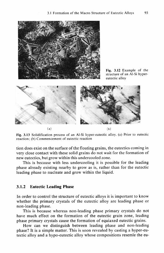
For those with such doubts, Fig. 3.13 shows some frames from a film showing the solidification process of an AI-18 % Si alloy.
One can easily ascertain the existence of grain boundaries by using a high-temperature microscope to watch while a eutectic alloy sample is heated, as the melting commences first at the grain boundaries of the eutectic grains.
Perhaps some people may wonder "Why does the surface of solid grains other than leading phase ones not cause the formation of eutectic grains even if these exist in the liquid ?"
In order for eutectics to form on the surface of such solids within the liquid, first a eutectic leading phase must nucleate and grow there. However, even if for instance sufficient undercooling for such eutectic forma-
3.1 Formation of the Macro Structure of Eutectic Alloys 93
(a)
Fig. 3.12 Example of the structure of an AI-Si hypereutectic alloy
(b)
Fig. 3.13 Solidification process of an AI-Si hyper-eutectic alloy. (a) Prior to eutectic reaction; (b) Commencement of eutectic reaction
tion does exist on the surface of the floating grains, the eutectics coming in very close contact with these solid grains do not wait for the formation of new eutectics, but grow within this undercooled zone.
This is because with less undercooling it is possible for the leading phase already existing nearby to grow as is, rather than for the eutectic leading phase to nucleate and grow within the liquid.
3.1.2 Eutectic Leading Phase
In order to control the structure of eutectic alloys it is important to know whether the primary crystals of the eutectic alloy are leading phase or non-leading phase.
This is because whereas non-leading phase primary crystals do not have much effect on the formation of the eutectic grain zone, leading phase primary crystals cause the formation of equiaxed eutectic grains.
How can we distinguish between leading phase and non-leading phase? It is a simple matter. This is soon revealed by casting a hyper-eutectic alloy and a hypo-eutectic alloy whose compositions resemle the eu-

94 3 Application of the Separation Theory
tectic compositon extremely closely, and comparing their solidified structures.
The phase in which primary crystals exist independently of the eutectic matrix is the non-leading phase, and the phase in which primary crystals form a core in the center of the equiaxedeutectic grains is the leading phase.
I have often encountered people who say "I have observed that CuAl2 does not always necessarily lead in the eutectics of AI-Cu alloys obtained by quenching during solidification." These people thought that the advancing interface is fixed by quenching. There is no reason why quenching would stop solidification, and rather the growth rate becomes extremely rapid. Here too the leading phase grows first and spreads out in a fan shape as in Fig.3.14, so the result is that the non-leading phase seems to project, and therefore one falls under the illusion that the non-leading phase grew more rapidly or that the leading phase and non-leading phase are growing identically.
cuAI2 ......... • __ i~ aAI---= ••••• I~~~
Gradual cooling Quenching Fig. 3.14 AI-Cu eutectic alloy quenched during solidification
Table 3.1. Leading phase of eutectic alloys
Leading Leading Leading Alloy phase Alloy phase Alloy phase
Ag-Bi Aga AI-AI9C02 A19C02" Bi-Cd Bi" Ag-Cu Cu AI-CuAI2 CuAI2 Bi-Sn Bi Ag-Ge Gea AI-NiAI} NiAI3 Cd-Pb Cda Ag}Sb-Sb Sba AI-Si Si Cd-Sn Cd" Ag}Sn-Sn Ag}Sn" AI-Sn Ala Cd-Zn Zna
AI-Ge Ge AI-Zn Al Fe-C C AI-AISb AISb" Bi-BiPb2 Bi Fe-Fe3C Fe3C
"see References no. 28
In Table 3.1 have listed the eutectic leading phases that have already been reported on and ones that I have selected as leading phases based on structural photos that I have come across in various papers.

3.1 Formation of the Macro Structure of Eutectic Alloys 95
3.1.3 Refining of Equiaxed Eutectic Grains
Here we have learnt that when leading phase primary crystal grains exist in the liquid, equiaxed eutectic grains form from these.
Consequently, in order to produce ingots with a structure consisting of fine equiaxed eutectic grains, what should be done first is to choose a eutectic alloy whose primary crystals are leading phase, and then disperse its primary crystals finely throughout the liquid.
In effect, this means causing many primary crystals to separate from the mould wall in the initial stage of solidification, and ensuring that as many as possible survive without melting again and disappearing.
In the case of alloys whose primary crystals easily grow largely along the mould wall, it is sufficient to curb the growth of crystals along the mould wall by using an appropriate additive and to ensure that the crystals can separate easily.
A typical example is the Si primary crystals of an AI-Si hyper-eutectic alloy. As shown in Figs. 3.12 and 3.13, these easily produce large angular crystals. The addition of P that suppresses their growth is effective in order to disperse these finely within the liquid.
N ext, let us discuss what to do in cases in which one desires a structure consisting only of columnar eutectic grains and no equiaxed eutectic grains. This is easy. Select a eutectic alloy whose primary crystals are non-leading phase and gently solidify it so that the molten metal does not move in the mould.
3.1.4 Separation of Eutectic Grains from the Mould Wall
I stated that equiaxed grains derive from the surface of eutectic leading phase primary crystal grains, but they sometimes form even without such primary crystals as their core. This occurs in cases when the eutectic grains themselves separate from the mould wall.
Generally eutectics demonstrate similar growth behavior to pure metals, and do not readily separate from the mould wall, but if the mould wall is roughened and strong stirring is carried out so that it is difficult for the eutectics to form a stable solid shell on the mould wall, in most cases they will separate.
Figure 3.15(a) shows the case of Zn-40/0Al. Since the primary crystals of this alloy are not leading phase, it is an alloy of the type whose primary crystals do not cause the formation of equiaxed eutectic grains. When this alloy was cast into a chamotte mould from 450 0 C, this structure was obtained whereby the columnar eutectic grains exist independently of the primary crystals.
By contrast, Fig. 3.15(b) shows the structure of an ingot obtained when vertical with an amplitude of 1 mm and a frequency of 50 cis were applied

96 3 Application of the Separation Theory
( a) ( b)
Fig.3.15 Effect of vibration on the solidified structure of an Zn-4%Al alloy. (a) Solidification when not vibrated; (b) Solidification when vibrated
A
grains [quiaxed eutectic r--c::;-___ .L
grains Primary crystals
B
[;>---::;:f-".-".--j Equiaxed r---~~L---.<:I eutectic
grains
Primary crystals Fig. 3.16 Schematic figure of the
structure of a eutectic system alloy when eutectic grains have also separated with the primary crystals. (a) Secondary phase primary crystals; (b) Leading phase primary crystals
to the mould. Equiaxed eutectic grains formed, and they existed independently of the primary crystals.
The reason that I used a chamotte mould with a small cooling capacity is that eutectics easily form a solid shell, so I deliberately did not use a metallic mould with a large cooling capacity.
Figure 3.16 is a schematic figure of the structure when eutectic grains also separated with the primary crystals of the eutectic alloy.
When vibration or stirring is used to separate eutectic grains from the mould wall, it is possible to produce equiaxed grains that do not contain a primary crystal core in the center.
When it is thus recognized that there are cases in which the eutectic grains themselves separate from the mould wall, it becomes very easy to

3.2 Solidification of Cast Iron 97
understand questions with regard to eutectic alloys that it was difficult to explain in the past.
A typical example is the explanation of the process by which an inverse chill structure is created in cast iron.
3.2 Solidification of Cast Iron and the Creation of an Inverse Chill Structure
I stated that a common phenomenon in eutectic alloys is the tendency for primary crystals to separate from the mould wall and gather in the center portion of the casting, and that the fewer the number of primary crystals, the more evident is this tendency.
I also pointed out that violent movement of the liquid can cause the eutectic grains themselves to separate from the mould wall.
As the reader is aware, cast iron is also a eutectic alloy, so the phenomena described so far as common features of eutectic alloys must also exist in cast iron. There is no reason why cast iron alone should be an exception.
However, the double phase diagram of cast iron is as shown in Fig. 3.17, and it is known that generally if cast iron is quenched it solidifies in accordance with the solid line phase diagram, and if cooled gradually it solidifies in accordance with the dotted line phase diagram. That is, it is known that when quenched the C dissolved within the molten metal of the cast iron easily forms the compound Fe3C, and if cooled gradually it easily crystallizes as graphite.
3 4 c (%)
Fig. 3.17 Equilibrium diagram for Fe-C system alloys
In other words, it is known that quenching cast iron produces a white cast iron structure, and cooling it gradually turns it into grey cast iron.
Looking at the fractures of iron castings, however, often there is a grey cast iron structure in the quenched surface layer of the casting, and white cast iron - the quenched structure of cast iron - appears inside it in the part

98 3 Application of the Separation Theory
Grey cast i ron
Whi te cast iron
Fig. 3.18 Example of inver e chill structure in cast iron
that should be cooled gradually, as shown in Fig. 3.18. This structure is referred to as an inverse chill structure.
Various reports exist with regard to the formation of such an inverse chill structure, but in every case they regard the white cast iron structure as having nucleated inside the casting, and I can find no reports that say as I am obout to that "The material for the white cast iron inside came from another location."
Conventionally it has been thought that "This occurs because elements that promote the formation of white cast iron (or elements that obstruct the formation of graphite) segregate in the center region of the casting."
In actual practice, however, it seems that people involved in casting iron have often encountered phenomena which are difficult to understand in line with this conventional explanation.
I was once questioned about inverse chill by a certain chilled roll manufacturer. The question was about inverse chill when a composite mould consisting of a sand mould and a metallic mould was used as in Figure 3.19(a) to cast molten iron by the bottom-pouring process so that the out-
(a) (b)
Fig. 3.19 Mould for chilled rolls (a) and schematic figure of the inverse chill that appeared in the chilled rolls

3.2 Solidification of Cast Iron 99
side of the roll barrel would consist of a hard white cast iron structure and the inside of a grey cast iron structure.
As shown in Fig. 3.19(b), a thick white cast iron structure formed in the surface layer, but the inside was also dotted with islands of white cast iron mixed in with the grey cast iron structure. The existence of such white cast iron on the inside reduces roll toughness and is undesirable, so this manufacturer decided to put conventional theory into practice and add elements that obstruct the formation of white cast iron so as to eliminate this problem.
Adding large amounts of Fe-Si alloys had the opposite effect of increasing the amount of white cast iron, and conversely the white cast iron layer in the surface became thinner.
How can this be explained to people who adhere to the conventional theory? No doubt it is impossible.
Application of the crystal separation theory provides an understanding of such problems also.
Just regard this as being due to the fact that the addition of large amounts of Fe-Si alloys delayed the formation of a stable white cast iron solid shell on the chill plate, and provided the Fe-Fe3C eutectic grains with an opportunity to separate.
Let me introduce a simple experiment I performed in order to understand the formation of such inverse chill. In what cases does inverse chill occur?
I made moulds such as those shown in Fig. 3.20. (a) consists entirely of a sand mould. Figure3.20(b) is a metallic mould, and in Fig. 3.20(c) to (e) a chill plate was set in part of a sand mould. Into these moulds I poured 3.39% CE and 3.87% CE hypo-eutectic cast iron. The pouring positions were varied.
The sand mould in Fig. 3.20(a) produced a structure consisting entirely of grey cast iron. The metallic mould in Fig. 3.20(b) produced a structure consisting entirely of white cast iron.
~.:. , •••. >.-:
'.: ,:" :.f~, ':i Chill ::,. " .. plate ."r.';.: ..
(cl
~ Metall iC mould
~ Chill plate
Fig. 3.20 Mould used in the study of inverse chill. (a) Sand mould; (b) Metallic mould; (c) - (e) Compound mould consisting of sand and a chill plate

100 3 Application of the Separation Theory
Fig. 3.21 The macro-structure of 3.390/0CE cast iron obtained in the mould shown in Figure 3.20 (e)
However, in the cast iron obtained from the composite moulds in Fig.3.20(c) to (e) in which chill plates were set, the part immediately in front of the chill plate had a white cast iron structure, but as the distance from this increased an inverse chill structure appeared in which the surface was a grey cast iron structure and the inside was a white cast iron structure.
Figure 3.21 is one example of this. The part in the middle immediately in front of the chill plate had a white cast iron structure, but on both sides of this a grey cast iron structure appeared in the surface layer of the white cast iron structure.
Figure 3.22 is a figure 129 presented at the Conference on the Solidification of Metals held at the University of Warwick in Coventry, England in 1980 in order to explain this in verse chill structure.
Quenching Gradual cooling
Fig. 3.22 Figure explaining the process of formation of inverse chill in hypo-eutectic cast iron

3.2 Solidification of Cast Iron 101
The formation of inverse chill can be explained if we consider that the white cast iron that had formed on top of the chill plate - i.e. Fe3C-Fe eutectic (ledeburite) - separated and shifted to a grey cast iron formation zone and was surrounded by Fe-graphite eutectic grains.
But no doubt the reader cannot accept this explanation either unless shown some evidence supporting it. Towards this end I conducted a simple experiment using a mould as shown in Fig. 3.23. When 3.87% CE cast iron was cast into such a mould, in the case of a mere sand mould the structure consisted entirely of grey cast iron, but inverse chill was produced merely by placing a small chill plate in part of the sprue runner.
When I explain this, I am often told that "Inverse chill appears in some case even without any chill plate." Of course. It does not mean that inverse chill cannot occur unless a chill plate is present.
It is sufficient if white cast iron is formed somewhere in the mould and separates. The example in the experiment I just showed you deliberately used molten metal that has a composition in which white cast iron does not appear when a mere sand mould is used. When a molten metal slightly more susceptible to turning into white cast iron is cast, inverse chill appears even in a sand mould, and conversely when the C and Si are increased inverse chill will not readily appear simply by placing such a chill plate in the sprue runner.
When I presented this explanation at the Conference on the Solidification of Metals at the University of Warwick, a member of the audience called out "Very clear."
I too was of that opinion. When I spoke at a lecture meeting of the Japan Foundrymen's Society in 1980, which is a gathering of Japanese cast iron specialists, I was told that "What you are referring to as inverse chill seems to be what we call mottled cast iron", and that "Inverse chill refers to structures in which the surface layer consists of grey cast iron and the
- 140----!---'70-
~ yr: .. : ...... : ..... :-' ....... f--55-
(a)
1 T
... ,'"'... " t " ' • ,. .. ~ _.,. . ~ . . " .. , ~ l ".. . '. I ..... ' .r- ... .
• 4f~ .. ~ J 1.', .-: ... ,
,
Fig. 3.23 Effect of a chill plate in the sprue runner on the macro structure of 3.87%CE cast iron. (a) With chill plate; (b) Without chill plate

102 3 Application of the Separation Theory
whole inside is white cast iron." I was amazed. I believe that it is inverse chill if the chill that should exist in the surface layer (quenched structure) exists on the inside, no matter what the amount, just as the opposite of normal segregation is called inverse segregation.
I often say to such people "Observe a casting in which inverse chiII exists, looking at it not locally but macroscopically. This should make you fully aware of the relationship between what you refer to as inverse chill and mottled cast iron."
If an examination of the local rupture surface of cast iron shows that inverse chill exists, it seems that there is a tendency to jump to the conclusion that the white cast iron formed at that site. But I would like readers to draw a mental picture of the whole casting - not just the casting itself, but also the ingate, the sprue runner and the gate - and search to see whether a place for the white cast iron to form and separate does not exist somewhere.
If the source of the formation of the white cast iron in this inverse chill part is known, I believe that measures to prevent inverse chill will naturally come to mind.
If inverse chill seems to appear even though there is no particular quenched place within the mould, efforts should be made to control the components of the molten metal, and molten metal that does not easily turn into white cast iron should be used, or the cooling capacity of the sand mould should be further reduced at places with which the molten metal comes in contact in the initial stage of pouring, such as the sprue runner or the gate or the bottom of the mould.
I often hear of cases in which inverse chiII sometimes appears and sometimes does not appear even though sand moulds made unter identical conditions are used. Of course this must be due to the fact that the components of the molten metal are not identical. Not only C and Si, but also the extent of oxidation has a major influence.
Thus the treatment of the molten metal is important in order to prevent inverse chill, but we must not forget the existence of the mould wall, which is the source of the formation of white cast iron structures. Depending on how the cooling capacity of the mould is controlled, it should be possible to prevent inverse chill.
Observing the structure of cast iron through a microscope, perhaps some readers may discover ledeburites threading through the primary crystal austenite grain boundaries, as in Fig. 3.24, and wonder why ones with such a complex configuration separate from the mould wall. The reader should realize that what he is looking at in this case is the final solidified structure. If small ledeburites move here and then grow, it is natural that they will thread through the gaps between the primary crystals.
This explanation of the mechanism by which inverse chill is created can be applied as is to the development of techniques aimed at dispersing uniformly the fine grains of carbides in cast iron. In order to scatter car-

3.3 Spherical Graphite Cast Iron and the Separation Theory 103
Fig. 3.24 Cementite eutectics that appeared in the primary crystal austenite grain boundaries
bides finely throughout cast iron, it is first necessary to ensure that it is difficult for them to form a stable solid shell on the mould wall. Moulds with a rough surface would be effective, as would stirring in the front part.
3.3 Spherical Graphite Cast Iron and the Separation Theory
In 1981 I visited Harbin Institute of Technology in China and gave a lecture on the principles of cast structure control. At that time I was asket "Is it absolutely impossible for free crystals to form anywhere except on the mould wall?" I then realized that my explanation of the formation of free crystals was lacking in some respects.
My separation theory explains the formation of free crystals in the case of very ordinary casting in which molten metal is poured into a cold mould. It does not discuss the nucleation of free crystals in cases in which measures are devised to completely prevent nucleation on the mould wall and in which the inside of the molten metal in the mould is partially undercooled. Since in actual practice there are cases in which free crystals are formed by such methods, however, let me discuss these cases.
The case of the formation of spheroidal graphite in spheroidal graphite iron is well known. In order to produce spheroidal graphite iron, in general the method is adopted of using a treatment container heated to a high temperature, as shown in Fig. 3.25_ Firstly an Mg alloy is placed on the base of the container and the cast iron molten metal is poured onto this, or firstly the molten metal is poured and the Mg alloy is pushed into this. This produces cast iron with great ductility and containing spheroidal graphite, as shown in Fig. 3.26.
I will now discuss how the separation theory plays an important role in obtaining such spheroidal graphite iron.

104 3 Application of the Separation Theory
Mg injector
( a) (b)
Fig. 3.25 Mg treatment of molten cast iron
Fig.3.26 Example of spheroidal graphite iron. (By courtesy of Mr. Masahiko Noguchi)
e e.' ,c _ e
e-
.... e
C I e
( a) (b ) (e)
Fig. 3.27 The structure of graphite, and flake and spheroidal graphite
Graphite has a laminated structure. As shown in Fig. 3.27(a), it also has the property of growing preferentially in the a-axis direction. Consequently, it grows into flake graphite, as in Fig. 3.27(b). By contrast, spheroidal graphite is a polycrystal body in which the c-axes of the respective crystals form a radiated shape. A nucleation point that acts as the origin of the polycrystal body must exist at the intersection of each c-axis.
When the cast iron molten metal wets on the mould wall a lot, crystals form preferentially on the mould wall, as in Fig. 3.28. Since these are graphite single crystals, they grow preferentially in the a-axis direction. Such crystals easily separate. As long as graphite is allowed to form on the

3.3 Spherical Graphite Cast Iron and the Separation Theory 105
~hite _
Fig. 3.28 Formation of flake graphite Fig. 3.29 Formation of spheroidal graphite
mould wall, spheroidal graphite cannot be obtained. In order to obtain spheroidal graphite, firstly the formation and separation of graphite on the mould wall must be prevented.
As I stated earlier, firstly the treatment container must be heated sufficiently. High-temperature molten metal is placed inside this and Mg is added and made to evaporate within the liquid. When a local undercooled zone is produced in the liquid, graphite forms around the solid alien grains and air bubbles in the liquid. If this alien matter is fine enough, the graphite grows to cover the whole surface of these grains, as in Fig. 3.29, and finally turns into spheroidal graphite.
Why is Mg effective in producing spheroidal graphite? Is it merely because it evaporates easily?
When I visited the Peking Iron and Steel Institute in 1982 I was shown some spheroidal graphite iron .that was reputedly made over 1,000 years ago. It is absolutely inconceivable that such spheroidizing agents as Mg and Ce existed at that time. One of the graduates from my laboratory has a foundry in a tangerine-producing area, and he told me that when tangerines were thrown into cast iron molten metal, the graphite became spheroidal. Solidification theory must also be capable of explaining the formation of spheroidal graphite 1,000 years ago and its formation through the use of tangerines.
One often hears that spheroidal graphite was produced empirically merely through an Fe-Si inoculation, without carrying out such Mg treatment. What is common in such cases is the fact that the molten metal is often deoxidized and desulfurized.
As the reader is aware, both 0 and S are molten iron surface activators, and are elements which reduce surface tension. In other words, these elements help cast iron molten metal to wet to the mould wall, and accelerate the nucleation of primary crystal graphite on the mould wall.
Conversely, therefore, removing these elements makes it difficult for the molten metal to wet to the mould wall. In effect, it restrains the formation of graphite crystals on the mould wall.
No doubt some readers will have realized that molten metal treated with Mg has a large surface tension. At the same time as it robs the molten metal of its heat by evaporation, Mg also makes it difficult for wetting to occur. It prevents graphite from forming and separating from the mould wall.

106 3 Application of the Separation Theory
(a) (b)
Fig. 3.30 Spheroidal Si in an Al-Si hyper-eutectic alloy obtained by Na treatment. (a) Spheroidal Si ; (b) Section of spheroidal Si. (By courtesy of Professor Q.c. Lee and Professsor P. Zhu of Harbin Institute of Technology)
Figure 3.30 resembles spheroidal graphite, but actually it shows not graphite but spheroidal Si crystals. I received this at Harbin Institute of Technology. It was produced by treating the molten metal of an AI-Si hyper-eutectic alloy with Na. It is extremely difficult to obtain such an AISi alloy consisting only of spheroidal Si, and inevitably flake Si is mixed in. This is because with Na treatment it becomes difficult to prevent completely the formation and separation from the mould wall of Si. If an additive and mould material in which such flake Si does not form and separate could be found, perhaps it would be possible to obtain an Al-Si hyper-eutectic alloy with such rich ductility as spheroidal graphite iron.
3.4 Separation Theory and Macrosegregation
Earlier I discussed the creation of inverse chill in cast iron. I said that inverse chill is one instance of inverse segregation, and stated that it is difficult to explain such segregation without the separation theory.
I would now like to round off my discussion of the relationship between macrosegregation and the separation theory.
3.4.1 Normal Segregation
When an alloy is poured into a mould and solidified, it is extremely difficult to obtain ingots whose whole composition is perfectly homogeneous. Unless such special methods as solidifying it over a long period in gravityfree space are adopted, it is probably impossible to do this on earth.

A B(%)
3.4 Separation Theory and Macrosegregation 107
Fig. 3.31 Phase diagram explanation of the solidification process of alloys
When an alloy solidifies, what first appears is a solid with a high melting point. I am sure those who have studied the equilibrium diagram of alloys are well-acquainted with this fact.
Phase diagrams show that in alloys having a phase diagram in which the liquidus slopes downwards, as in Fig. 3.31, when the liquid of an alloy with a Co composition is cooled, the primary crystals S, crystallize at the temperature t, on the phase diagram, and at temperature t2 they turn into the solid with the original Co composition.
This is strictly in a case which assumes that the solute is sufficiently diffused either within the liquid or within the crystallized solid phase, and such solidification is entirely out of the question in actual casting, where cooling takes place rapidly.
In cases in which not only is the diffusion of the solute within the solid slow, but also there is no time for the liquid to be fully mixed within the residual liquid, the solute concentration increases in the part of the ingot that solidifies last, as in Fig. 3.32(a). A composition with a high melting point on the outside and a composition with a low melting point inside come together. Such segregation is called normal segregation.
The wider apart are the liquidus and the solidus of alloys on an equilibrium diagram, the more clearly does this macrosegregation appear.
Low meillng point composition
Fig. 3.32 Normal segrega· tion and inverse segregation of an alloy ingot

108 3 Application of the Separation Theory
Here I have discussed the example of alloys in which the liquidus temperature falls as the solute concentration rises, as in Fig. 3.31, but in actual fact there are alloys in which the liquidus temperature rises as the solute concentration increases. Explaining this is a complex matter, however, so the reader should just think of the former case in reverse.
3.4.2 Inverse Segregation
By contrast, there are cases in which the solute concentration of the center part that should solidify afterwards is lower than that of the outside of the ingot, as in Fig. 3.32(b). To put it another way, there are cases in which the high melting-point zone lies in the center rather than in the outer region of the ingot. This often occurs in the case of alloy castings. A typical example is the zone referred to as the low-concentration negative segregation of impurities that often appear in the lower center part of steel ingots. The AI-Cu alloy that I introduced earlier when discussing the distribution of the primary crystals of eutectic alloys is a fine example of this. I presented a photo in which primary crystals with a high melting point are in the center and eutectics with a low melting point exist on the outer region. Without going so far as to analyze this, let me just say that segregation of the primary crystal components exists in the center. I call such segregation inverse segregation.
The separation theory is extremely useful in understanding the mechanism of the creation of such inverse segregation and in considering how to prevent it. If one attempts to explain the creation of inverse segregation without relying on the separation theory, the explanation becomes unreasonable and difficult to understand.
IS!
~ \ .... => 14 u
13 0
..... -
Top
20 40 60 80
Distance from chill plate (mm)
?
100 Fig. 3.33 Inverse segregation that appeared in an AI-14%Cu alloy
It is well-known that inverse segregation occurs in AI-Cu alloys. Figure 3.3330 is one example of inverse segregation obtained in an AI-140/0 Cu alloy. A thin layer with a high Cu concentration appeared in the cooled end. Columnar crystals grew from the cooled end and an equiaxed zone with a low Cu concentration appeared in front of that.
I am sure no explanation is required of why the Cu concentration of this equiaxed zone is low. Using the equipment shown in Fig. 3.34, I firstly

3.4 Separation Theory and Macrosegregation 109
container
Fig. 3.34 Observation of the process of formation of inverse segregation using an Sn alloy
observed the formation, separation and movement of the equiaxed crystals of an Sn-Bi alloy. I then analyzed the ingot after solidification and confirmed the appearance of inverse segregation in the zone in which primary crystal Sn had sedimented.
I would like to add here that the precipitation of equiaxed crystals does not necessarily mean that inverse segregation will always occur there. It is fine if crystals separate in the initial stage of solidification and densely precipitate and sediment as is, but in cases in which the separated crystals float within the liquid and finally precipitate within the residual liquid with a low melting point composition in which solute is concentrated, they capture this solute concentrate between the crystal grain boundaries and the dendrites, so it no longer means that inverse segregation will always appear there just because there are equiaxed crystals.
Probably the reader will have more difficulty understanding cases in which there is a thin segregation layer with a low melting point composition on the ingot surface, rather than cases of such inverse segregation at the tip that solidifies last.
Through decantation I removed the residual liquid at various stages in the solidification of an AI-40/0 alloy, and analyzed the eu concentration of the solid shell. The results30 showed that, as in Fig. 3.35, a layer in which eu was concentrated had already formed on the outer layer by the time a stable solid shell had formed, and no tendency was seen for the eu concentration of the outer layer to increase with the passage of time.
~ :>
U
4.4 ,I 1 1 . " . I
, '- . \, I
4. 0
3.6 I-(a)- l-(b)l- - I-I( c ~ I( d ~~ - I-
o 20020400204060
Distance from chill plate ( mm)
Fig. 3.35 Formation of Cu concentrated layer on the surface of an AI-4%Cu alloy
Figure 3.36 shows the course of the formation of the solute concentration layer on the outer layer. The primary crystals with a high melting point composition that had formed and separated on the mould wall shift

110 3 Application of the Separation Theory
Soloddication interiae
Fig. 3.36 Formation of the solute-concentrated layer on the surface of alloys
rapidly. The solute concentration of the residual liquid in contact with the mould wall increases. Finally a stable solid shell begins to form on the mould wall.
It is easier to understand this if one considers that the solute concentrate that was captured by the roots of the crystals on the mould wall and thus cut offfrom escape forms the segregation of the outer layer.
3.4.3 String Segregation
In cases when the crystals precipitate and sediment and a pool of residual liquid is captured among the crystals as in Fig. 3.37(a), if the specific gravity of the liquid in which the solute was concentrated falls as the residual liquid solidifies, the residual liquid shifts upwards as if threading its way among the trees of the crystals. If conversely the specific gravity rises, it moves downwards and produces string-shaped segregation. A typical example of this string segregation would be the inversed V segregation of steel ingots, as shown in Fig. 3.37(b).
NegalIVe IOn
(a)
(b)
Fig. 3.37 Formation and structure of string segregation. (a) Capturing of residual pool; (b) Inverse V segregation in an ingot

3.4 Separation Theory and Macrosegregation III
In order to prevent such string segregation, it is therefore necessary to find a solidification method which does not create a pool of residual liquid captured among the trees of the crystals.
With steel it is known3l that reducing the amount of Si or adding Mo makes the gaps among the branches of the dendrites more dense and makes it difficult for inverse segregation to occur.
3.4.4 Band Segregation
Even when equiaxed crystals are not formed, sometimes band-shaped segregation appears repeatedly. This occurs when the solute enriched liquid concentrated in the advancing interface is unable to escape and is captured among the trees of the crystals, as in Fig. 3.38. In order to prevent such segregation, I believe that it is necessary to provide some mechanical cleaning action that will remove the concentrate of the advancing interface before it is captured among the crystals.
Band segreg.hon Advanc"g ,nterf,ce of IIquod
Molt." melal
So~ Caplu,,"s of solute concentrate Fig.3.38 Formation of band segregation
I have been asked "Cementite appeared as band segregation in cast iron with a hypo-eutectic composition. Why did band-shaped cementite segregation occur?" In such cases it is a mistake to think that the cementite formed there. When investigating the process by which segregation occurs, it must be kept in mind that since cast iron is a eutectic alloy, after primary crystal austenite first crystallizes the eutectic molten liquid fills in among the crystal trees. What thrust aside the primary crystal austenite and produced band-shaped crevices? In most cases such segregation occurs after gas bubbles have passed through. The austenite is pushed aside and eutectic molten liquid with a low melting point fills in where the gas bubbles have passed. Consequently, in order to prevent such band segregation, firstly it is necessary to prevent any source of gas. It is necessary to check whether there was any gas source in the mould and whether there was anything within the flux used that would generate gas.

112 3 Application of the Separation Theory
3.4.5 Gravity Segregation
As long as solidification is carried out on earth, I think it will be difficult to avoid gravity segregation. When crystal formation and separation occur at the mould wall, the crystals will precipitate or float to the surface as long as gravity exists. Along wifh this the liquid will also move. It is quite difficult for the solute concentration of the molten metal to be perfectly homogeneous throughout the whole mould, and the liquid concentration varies in certain local parts of the mould wall, and depending on the site sometimes crystal nucleation differing from that in other place occurs. Such examples are often seen in the solidification of eutectic alloys with a composition close to eutectic point.
Frequently it happens that even though hypo-eutectic molten metal was cast, hyper-eutectic primary crystals coexist along with the hypo-eutectic primary crystals. For instance, Fig. 3.39 shows the segregation obtained when an Sn-Ph alloy was solidified. When an alloy with a hypo-
- Sn primary crystals
- Pb primary crystals

3.5 Separation Theory and the O.c.c. Process 113
eutectic composition was quenched only hypo-eutectic primary crystals were distributed throughout the whole, but when it was cooled gradually both kinds of primary crystals appeared separately in the upper and lower parts. This is regarded as being due to the fact that the formation, separation and floating up (or precipitation) of the primary crystals caused the composition of the liquid in local contact with the mould wall to become hyper-eutectic. Apparently this phenomenon frequently occurs in either the hypo-eutectic or hyper-eutectic side of eutectic alloys. It also seems to be related to the specific gravity of the primary crystals, and is an interesting topic that should be taken up in future research.
3.5 Separation Theory and the O.C.C. Process
So far I have discussed how "Application of the separation theory makes it relatively easy to explain various issues with regard to the solidification of metals that had been regarded as difficult to understand in the past."
It seems, however, that people who adhere to the old concepts cannot readily accept the separation theory. When papers on the formation of equiaxed crystals or the refining of crystals are published, I firstly open up to the last page and check whether or not our papers have been used as references, but in nearly all cases they are not.
I feel that acceptance of the separation theory would lead to the birth of one after another new techniques for cast structure control. Conversely, however, this failure to accept the theory provides those of us with little equipment or funds with plenty of time to develop new casting techniques.
Let me conclude by introducing as one example of these techniques the O.c.c. Process' that I developed recently.
O.C.C. is an abbreviation for Ohno Continuous Casting, and is a process for continuously casting metal materials with any desired sectional form and consisting only of a unidirectionally solidified structure with absolutely no equiaxed crystals.
Since ingots solidify first from the inside and the surface solidifies last, this process enables the casting of beautiful materials with a smooth surface and having no segregation of impurities or gas bubbles and cavities inside. When the ingot is a fine wire or thin plate, it is easy to produce a structure consisting only of single crystals and having absolutely no crystal grain boundaries.
No doubt the reader will think "Something like a cold wire must have been inserted continuously inside, or else how would it be possible to actually cause solidification from the inside first?" But this is possible in actu-
* Ohno A (Japan patent) 1049146; (U.S.A. patent) 4515204; (German patent) 3246470

114 3 Application of the Separation Theory
al practice. Figure 3.40 shows Al ingots cast continuously by the O.C.C. process, and their macro structures. The specular surfaces and the long crystals growing unidirectionally were actually produced by continuous casting.
There are various conventional methods of continuous casting of ingots, but their principles are fundamentally similar, involving pouring molten metal into a cooled hollow mould and causing many crystals to nucleate and grow on the mould wall, and then extracting the ingot after a stable solid shell has formed. When such processes are used, the ingots solidify from the sides inwards, as shown in Fig. 3.41(a), so impurities and gas are concentrated in the center part of the ingots. Cavities frequently form there. Many crystals exist, so naturally impurities and microscopic defects exist in their grain boundaries.
With the rapid development of the electronics industry recently, equipment has become increasingly compact and precise, and demands have arisen for the metal materials used to be of higher quality material, finer and thinner. For instance, extremely fine wires and thin plates with a diameter and thickness of 10 microns or 20 microns and no internal defects have become necessary, such as lead frames and bonding wires for use in ICs and LSIs. At this stage, the crystal structure of the ingot and such casting defects as segregation and gas in the center of the ingot,
B
Fig. 3.40 99.8%AI and AI-I %Si alloy ingot cast continuously by the O.C.c. Process. A. B. C. Surface; D. E. Etched structure; A. 30 mm diameter AI; B. 12 mm diameter AI ; C. 20 mm diameter AI-Si ; D. 30 mm diameter AI; E. 20 mm diameter AI

(a)
Coolong water
3.5 Separation Theory and the O.C.C. Process 115
Molten - metal -
(b)
Heated mould
Molten metat film
Fig. 3.41 Principle of the O .. c. Prote . (a) onventional method ; (b) O. . . Proce
which is the original material prior to plastic working, come to have a great effect on the nature of the product. Extremely fine wire breaks during working, and such defects as very fine holes occur in foil.
Recently there have also been calls for materials with no crystal grain boundaries, which in the past was inconceivable, such as copper wires for use in acoustic equipment and the memory disks of computers.
Those of us engaged in cast solidification must supply ingots capable of meeting these sophisticated demands for materials that keep pace with the progress made in such advanced technology. Based on my past research, I developed the O.CC process in order to respond to such demands.
Figure 3.41(b) illustrates the principle of the O.C.C process. When a heated mould is used instead of the conventional cold mould and the temperature of the inside walls of the mould are maintained above the solidification temperature of the cast metal and cooling of the ingot is conducted outside of the mould, solidification of the ingot avoids the mould wall and proceeds without any opportunity for equiaxed crystals to form and separate. If the temperature distribution within the mould is chosen skilfully, it is possible to produce a solidification interface shaped as if projection out within the mould. When this is done, the center part of the ingot solidifies first, and only the thin surface layer solidifies finally immediately outside of the mould.
This completely prevents crystals from forming and separating on the mould wall, so the ingots consists of a perfect unidirectionally solidified structure having absolutely no equiaxed crystals. Under this method, there is no opportunity for fresh crystals to form, and the crystals decline in number as they grow by competing against each other, so it is extremely easy to obtain ingots composed of single crystals. Since there is no friction between the mould wall and the ingot, the surface of the ingot is smooth and beautiful. Materials with various complex sectional forms, including of course a round or square form, can be obtained by direct casting. It is

116 3 Application of the Separation Theory
also possible to produce plates and tubes continuously from hard and brittle alloys, which is difficult by plastic working.
Looking at Fig.3.4I(b), no doubt the reader will think that the molten metal would burst forth from the bottom of the mould, and that it would be quite impossible to carry out this process. This figure merely demonstrates the principle of the process, and in order to actually use this in continuous casting, measures must be taken to ensure that the molten metal does not gush out from the mould exit. That is, a method must be used which reduces the molten metal pressure at the exit end of the mould to almost zero.
It was six years ago in 1978 that I thought of this O.C.c. process. I devised this in order to cast specular ingots continuously without any friction with the mould.
Firstly I wound nichrome wire around a heat-proof glass tube with an inner diameter of 10 mm, as in Fig. 3.42(a), and made a heated mould, and placed this vertically and set an iron dummybar in its bottom end. For water cooling I opened a hole in the bottom of a plastic bowl and dropped the dummy bar though it and supplied water inside this bowl. Gradually pouring the Sn melted in the mould, I lowered the dummy bar. Since I used a jack used when cars break down as the apparatus for lowering the dummy bar, the center of the dummy bar would not easily remain fixed , and though a specular ingot was somehow obtained for the first 50 mm or so at the most, the molten metal soon burst out from the bottom of the mould. I had no funds to make any grand equipment, and manufacturing on a commercial scale seemed extremely difficult, so I soon abandoned the experiment. I did apply for a patent, but I had no thought of paying money and registering it even if a patent was obtained in the future.
When I attended the Conference on the Solidification of Metals at the University of Warwick in Coventry in 1980, I was listening to an address
Molten metal Heated mould
(a) (b)
rott
(el
Fig. 3.42 Casting method utilizing the O.C.C. principle. (a) Downwards continuous casting ; (b) Siphon-type downwards casting; (c) Upwards continuous casting ; (d) Horizontal continuous casting

3.5 Separation Theory and the O.C.c. Process 117
by Professor M. C. Flemings of MIT on "Process modelling and process development". This included an introduction of the continuous casting process for iron developed by Dr. Eisuke Niiyama and his colleagues at Hitachi, Ltd. This was a continuous casting process using a steel belt and wheels with a groove shape on the periphery, and refined and applied to the continuous casting of iron the Properzi process and SCR process, which had long been used in the continuous casting of aluminum and copper as methods of continuously casting ingots with a beautiful surface without any friction with the mould. Listening to this address, I recalled the O.C.c. experiment that I had abandoned five years earlier.
After the address I told Dr. Niiyama of my O.C.C. idea. He strongly urged me "That's interesting. It may be of use for something, even if not for the continuous casting of iron, which has a high melting point, so don't give up. You should definitely keep at it." I returned to Japan and immediately began to consider methods in which breakout would not occur.
"Why does breakout occur? Because the pressure of the molten metal is exerted on the exit end of the mould. So if the pressure of the molten metal at the mould exit is zero, continuous casting without breakout would be possible." I immediately formed the molten metal feed pipe connecting the holding furnace and the heated mould into a siphon shape, as in Fig. 3.42(b), and ensured that the surface of the molten metal in the holding furnace and the lower end of the heated mould were maintained at the same level. I succeeded in continuously casting bar and tube ingots downwards. However, this process also has its defects. Making the molten metal feed pipe is very difficult in itself, and cleaning inside it is extremely difficult. In addition, there is no place in the mould for gas released during solidification to escape.
In my next experiment I immersed the mould to the surface of the molten metal in the holding furnace, as in Fig. 3.42( c), and held the upper end of the mould at the level of the surface of the molten metal, and after bringing a dummy bar into contact with the molten metal in the mould, I drew it upwards. With this method there is absolutely no risk of breakout. Nevertheless there was the problem that even if cooling by gas is possible, water cooling is difficult for industrialization.
The method I finally arrived at was to extract the ingots sideways from a mould set horizontally at a level directly below the surface of the molten metal in the holding furnace, as in Fig. 3.42(d). With this method water can be used as the coolant and it is easy to cast thin plates or wire rods continuously. Moreover, if a top-open mould is used, the gas released by the solidification interface can escape, and the location of the solidification interface within the mould can be observed, thus greatly facilitating operations.
The ingots produced by this process can be continuously cast to produce plate or bar ingots that all have a smooth and beautiful surface and only a unidirectionally solidified structure with no central segregation. In

118 3 Application of the Separation Theory
the past only short single crystals could be obtained, but this enables single crystals unlimited in length to be easily produced. Single crystal wires and plates and tubes can be obtained easily. This is one instance of what I said at the outset that "Application of the separation theory will enable the development of new casting techniques that will make it possible to supply materials suited to contemporary demands."