solid-state multi-functional timers h3cr-a
TRANSCRIPT
CSM_H3CR-A_DS_E_6_1
1
Solid-state Multi-functional Timers
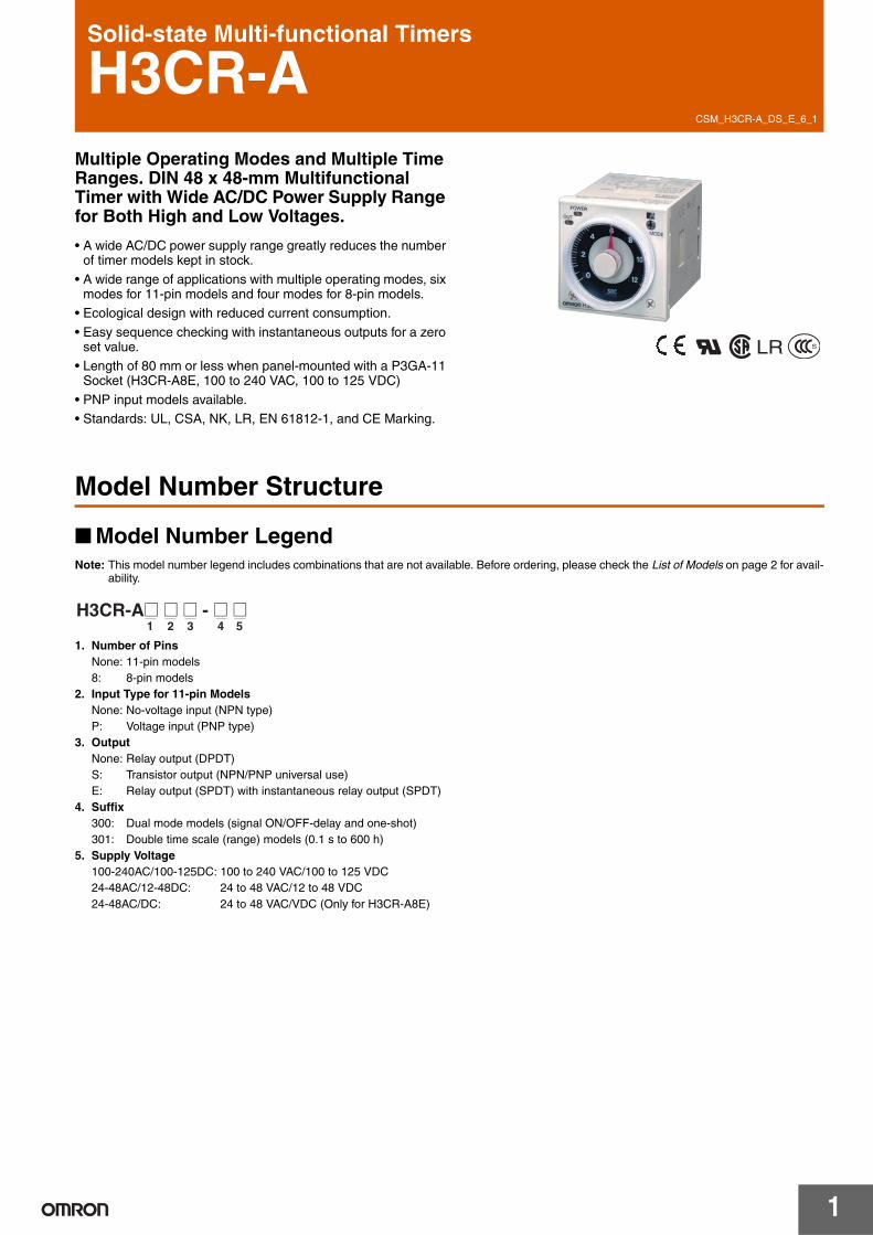
H3CR-AMultiple Operating Modes and Multiple Time Ranges. DIN 48 x 48-mm Multifunctional Timer with Wide AC/DC Power Supply Range for Both High and Low Voltages.
• A wide AC/DC power supply range greatly reduces the number of timer models kept in stock.
• A wide range of applications with multiple operating modes, six modes for 11-pin models and four modes for 8-pin models.
• Ecological design with reduced current consumption.
• Easy sequence checking with instantaneous outputs for a zero set value.
• Length of 80 mm or less when panel-mounted with a P3GA-11 Socket (H3CR-A8E, 100 to 240 VAC, 100 to 125 VDC)
• PNP input models available.• Standards: UL, CSA, NK, LR, EN 61812-1, and CE Marking.
LR
Model Number Structure
Model Number LegendNote: This model number legend includes combinations that are not available. Before ordering, please check the List of Models on page 2 for avail-
ability.
1. Number of PinsNone: 11-pin models8: 8-pin models
2. Input Type for 11-pin ModelsNone: No-voltage input (NPN type)P: Voltage input (PNP type)
3. OutputNone: Relay output (DPDT)S: Transistor output (NPN/PNP universal use)E: Relay output (SPDT) with instantaneous relay output (SPDT)
4. Suffix300: Dual mode models (signal ON/OFF-delay and one-shot)301: Double time scale (range) models (0.1 s to 600 h)
5. Supply Voltage100-240AC/100-125DC: 100 to 240 VAC/100 to 125 VDC24-48AC/12-48DC: 24 to 48 VAC/12 to 48 VDC24-48AC/DC: 24 to 48 VAC/VDC (Only for H3CR-A8E)
H3CR-A@ @ @ - @ @1 2 3 4 5
H3CR-A
2
Ordering Information
List of Models
11-pin Models
8-pin Models
Supply voltage
Note: 1. Specify both the model number and supply voltage when ordering. Example: H3CR-A 100-240AC/100-125DC
2. The operating modes are as follows A: ON-delay D: Signal OFF-delay B: Flicker OFF start E: Interval B2: Flicker ON start G: Signal ON/OFF-delay C: Signal ON/OFF-delay J: One-shot
Output Supply voltage Input type Time range Operating mode (See note 2)
Model(See note 1.)
Contact 100 to 240 VAC (50/60 Hz)/100 to 125 VDC
No-voltage input 0.05 s to 300 h Six multi-modes: A, B, B2, C, D, E
H3CR-A
24 to 48 VAC (50/60 Hz)/12 to 48 VDC
100 to 240 VAC (50/60 Hz)/100 to 125 VDC
Dual-modes: G, J H3CR-A-300
24 to 48 VAC (50/60 Hz)/12 to 48 VDC
100 to 240 VAC (50/60 Hz)/100 to 125 VDC
Voltage input Six multi-modes: A, B, B2, C, D, E
H3CR-AP
24 to 48 VAC (50/60 Hz)/12 to 48 VDC
100 to 240 VAC (50/60 Hz)/100 to 125 VDC
No-voltage input 0.1 s to 600 h H3CR-A-301
24 to 48 VAC (50/60 Hz)/12 to 48 VDC
Transistor (Photocoupler)
24 to 48 VAC (50/60 Hz)/12 to 48 VDC
0.05 s to 300 h H3CR-AS
Output Supply voltage Input type Time range Operating mode (See note 2)
Model(See note 1.)
Contact 100 to 240 VAC (50/60 Hz)/100 to 125 VDC
No-input available 0.05 s to 300 h Four multi-modes: A, B2, E, J(Power supply start)
H3CR-A8
24 to 48 VAC (50/60 Hz)/12 to 48 VDC
100 to 240 VAC (50/60 Hz)/100 to 125 VDC
0.1 s to 600 h H3CR-A8-301
24 to 48 VAC (50/60 Hz)/12 to 48 VDC
Transistor (Photocoupler)
24 to 48 VAC (50/60 Hz)/12 to 48 VDC
0.05 s to 300 h H3CR-A8S
Time-limit contact and instantaneous contact
100 to 240 VAC (50/60 Hz)/100 to 125 VDC
H3CR-A8E
24 to 48 VAC/VDC (50/60 Hz)
H3CR-A
3
Accessories (Order Separately)
Note: 1. Y92A-48G is a finger safe terminal cover which is attached to the P3G-08 or P3GA-11 Socket.2. The Time Setting Ring cannot be used alone. It must be used together with the Panel Cover.3. Hold-down Clips are sold in sets of two.
Specifications
General
*The internal circuits are optically isolated from the output. This enables universal application as NPN or PNP transistor.
Name/specifications Models
Flush Mounting Adapter Y92F-30
Y92F-73
Y92F-74
Mounting Track 50 cm (l) × 7.3 mm (t) PFP-50N
1 m (l) × 7.3 mm (t) PFP-100N
1 m (l) × 16 mm (t) PFP-100N2
End Plate PFP-M
Spacer PFP-S
Protective Cover Y92A-48B
Track Mounting/Front Connecting Socket
8-pin P2CF-08
8-pin, finger safe type P2CF-08-E
11-pin P2CF-11
11-pin, finger safe type P2CF-11-E
Back Connecting Socket 8-pin P3G-08
8-pin, finger safe type P3G-08 with Y92A-48G (See note 1)
11-pin P3GA-11
11-pin, finger safe type P3GA-11 with Y92A-48G (See note 1)
Time Setting Ring (See note 2) Setting a specific time Y92S-27
Limiting the setting range Y92S-28
Panel Cover Light gray (5Y7/1) Y92P-48GL
Black (N1.5) Y92P-48GB
Medium gray (5Y5/1) Y92P-48GM
Hold-down Clip (See note 3) For PL08 and PL11 Sockets Y92H-7
For PF085A Socket Y92H-8
Item H3CR-A/-AS H3CR-AP H3CR-A8/-A8S H3CR-A8E
Operating mode A: ON-delayB: Flicker OFF startB2: Flicker ON startC: Signal ON/OFF-delayD: Signal OFF-delayE: IntervalG: Signal ON/OFF-delay (Only for H3CR-A-300)J: One-shot (Only for H3CR-A-300)
A: ON-delay (power supply start)B2: Flicker ON start (power supply start)E: Interval (power supply start)J: One-shot (power supply start)
Pin type 11-pin 8-pin
Input type No-voltage input Voltage input ---
Time-limit output type H3CR-A/-A8/-AP: Relay output (DPDT)H3CR-AS/-A8S: Transistor output (NPN/PNP universal)*
Relay output (SPDT)
Instantaneous output type --- Relay output (SPDT)
Mounting method DIN track mounting, surface mounting, and flush mounting
Approved standards UL508, CSA C22.2 No.14, NK, LloydsConforms to EN61812-1 and IEC60664-1 (VDE0110) 4kV/2.Output category according to EN60947-5-1 for Timers with Contact Outputs.Output category according to EN60947-5-2 for Timers with Transistor Outputs.
H3CR-A
4
Time RangesNote: When the time setting knob is turned below “0” until the point where the time setting knob stops, the output will operate instantaneously at
all time range settings.
Standard (0.05-s to 300-h) Models
Double (0.1-s to 600-h) Models
Ratings
Note: 1. DC ripple rate: 20% max. (A single-phase, full-wave-rectification power supply can be used).2. Do not use an inverter output as the power supply. Refer to Safety Precautions for All Timers for details.3. Models with 24-to-48-VAC or 12-to-48-VDC power supply have inrush current. Caution is thus required when turning ON and OFF power
to the Timer with a non-contact output from a device such as a sensor. (Models with an inrush current of approximately 50 mA and a 24-VDC power supply are available (the H3CR-A-302 and H3CR-A8-302).)
4. The values are for when the terminals 2 and 7 and terminals 10 and 6 are short-circuited, and include the consumption current of the input circuit.
5. Refer to Safety Precautions for All Timers when using the Timer together with a 2-wire AC proximity sensor.
Time unit s (sec) min (min) h (hrs) ×10 h (10 hrs)
Full scale setting
1.2 0.05 to 1.2 0.12 to 1.2 1.2 to 12
3 0.3 to 3 3 to 30
12 1.2 to 12 12 to 120
30 3 to 30 30 to 300
Time unit s (sec) min (min) h (hrs) ×10 h (10 hrs)
Full scale setting
2.4 0.1 to 2.4 0.24 to 2.4 2.4 to 24
6 0.6 to 6 6 to 60
24 2.4 to 24 24 to 240
60 6 to 60 60 to 600
Rated supply voltage (See notes 1, 2, and 5.) 100 to 240 VAC (50/60 Hz)/100 to 125 VDC, 24 to 48 VAC (50/60 Hz)/12 to 48 VDC (24 to 48 VAC/VDC for H3CR-A8E) (See note3.)
Operating voltage range 85% to 110% of rated supply voltage (90% to 110% at 12 VDC)
Power reset Minimum power-opening time: 0.1 s
Input No-voltage InputON impedance: 1 kΩ max.ON residual voltage: 1 V max.OFF impedance: 100 kΩ min.Voltage InputMax. permissible capacitance between inputs lines (terminals 6 and 7): 1,200 pFLoad connectable in parallel with inputs (terminals 6 and 7).• 100 to 240 VAC/100 to 125 VDC
High (logic) level: 85 to 264 VAC/85 to 137.5 VDCLow (logic) level: 0 to 10 VAC/0 to 10 VDC
• 24 to 48 VAC/12 to 48 VDCHigh (logic) level: 20.4 to 52.8 VAC/10.8 to 52.8 VDCLow (logic) level: 0 to 2.4 VAC/0 to 1.2 VDC
Power consumption H3CR-A/-A8• 100 to 240 VAC/100 to 125 VDC
(When at 240 VAC, 60 Hz)Relay ON: approx. 2.0 VA (1.6 W) Relay OFF: approx. 1.3 VA (1.1 W)
• 24 to 48 VAC/12 to 48 VDC(When at 24 VDC)
Relay ON: approx. 0.8 W Relay OFF: approx. 0.2 WH3CR-AP (See note 3)• 100 to 240 VAC/100 to 125 VDC
(When at 240 VAC, 60 Hz)Relay ON: approx. 2.5 VA (2.2 W) (See note 4.) Relay OFF: approx. 1.8 VA (1.7 W) (See note 4.)
• 24 to 48 VAC/12 to 48 VDC(When at 24 VDC)
Relay ON: approx. 0.9 W (See note 4.) Relay OFF: approx. 0.3 W (See note 4.)H3CR-A8E• 100 to 240 VAC/100 to 125 VDC
(When at 240 VAC, 60 Hz)Relay ON/OFF: approx. 2 VA (0.9 W)
• 24 to 48 VAC/VDC(When at 24 VDC)
Relay ON/OFF: approx. 0.9 WH3CR-AS/-A8S• 24 to 48 VAC/12 to 48 VDC
(When at 24 VDC)Output ON: 0.3 W Output OFF: 0.2 W
Control outputs Time limit contacts: 5 A at 250 VAC/30 VDC, 0.15 A at 125 VDC, resistive load (cosφ = 1)Transistor output: Open collector (NPN/PNP), 100 mA max. at 30 VDC max.,
residual voltage: 2 V max.Instantaneous contact: 5 A at 250 VAC/30 VDC, 0.15 A at 125 VDC, resistive load (cosφ = 1)

H3CR-A
5
Characteristics
Note: 1. The value is ±5% FS +100 ms to −0 ms max. when the C, D, or G mode signal of the H3CR-AP is OFF.2. Refer to the Life-test Curve.
Life-test Curve
Accuracy of operating time
±0.2% FS max. (±0.2%±10 ms max. in a range of 1.2 s or 3 s)
Setting error ±5% FS ±50 ms (See note 1)
Reset time Min. power-opening time: 0.1 s max.Min. pulse width: 0.05 s (H3CR-A/-AS)
Reset voltage 10% max. of rated supply voltage
Influence of voltage ±0.2% FS max. (±0.2%±10 ms max. in a range of 1.2 s or 3 s)
Influence of temperature ±1% FS max. (±1%±10 ms max. in a range of 1.2 s or 3 s)
Insulation resistance 100 MΩ min. (at 500 VDC)
Dielectric strength 2,000 VAC (1,000 VAC for H3CR-A@S), 50/60 Hz for 1 min (between current-carrying metal parts and exposed non-current-carrying metal parts)2,000 VAC (1,000 VAC for H3CR-A@S), 50/60 Hz for 1 min (between control output terminals and operating circuit)2,000 VAC, 50/60 Hz for 1 min (between contacts of different polarities)1,000 VAC, 50/60 Hz for 1 min (between contacts not located next to each other)2,000 VAC, 50/60 Hz for 1 min (between input and control output terminals and operation circuit) for H3CR-AP
Impulse withstand voltage
3 kV (between power terminals) for 100 to 240 VAC/100 to 125 VDC, 1 kV for 24 to 48 VAC/12 to 48 VDC4.5 kV (between current-carrying terminal and exposed non-current-carrying metal parts) for 100 to 240 VAC/100 to 125 VDC, 1.5 kV for 24 to 48 VAC/12 to 48 VDC and 24 to 48 VAC/VDC
Noise immunity ±1.5 kV (between power terminals) and ±600 V (between no-voltage input terminals), square-wave noise by noise simulator (pulse width: 100 ns/1 µs, 1-ns rise)
Static immunity Malfunction: 8 kVDestruction: 15 kV
Vibration resistance Destruction: 10 to 55 Hz with 0.75-mm single amplitude each in 3 directions for 2 hours eachMalfunction: 10 to 55 Hz with 0.5-mm single amplitude each in 3 directions for 10 minutes each
Shock resistance Destruction: 1,000 m/s2 3 times each in 6 directionsMalfunction: 100 m/s2 3 times each in 6 directions
Ambient temperature Operating: −10°C to 55°C (with no icing)Storage: −25°C to 65°C (with no icing)
Ambient humidity Operating: 35% to 85%
Life expectancy Mechanical: 20,000,000 operations min. (under no load at 1,800 operations/h)Electrical: 100,000 operations min. (5 A at 250 VAC, resistive load at 1,800 operations/h) (See note 2)
EMC (EMI) EN61812-1Emission Enclosure: EN55011 Group 1 class AEmission AC Mains: EN55011 Group 1 class A(EMS) EN61812-1Immunity ESD: IEC61000-4-2: 6 kV contact discharge (level 3)
8 kV air discharge (level 3)Immunity RF-interference from AM Radio Waves: IEC61000-4-3: 10 V/m (80 MHz to 1 GHz) (level 3)Immunity RF-interference from Pulse-modulated Radio Waves:IEC61000-4-3: 10 V/m (900±5 MHz) (level 3)Immunity Conducted Disturbance: IEC61000-4-6: 10 V (0.15 to 80 MHz) (level 3)Immunity Burst: IEC61000-4-4: 2 kV power-line (level 3)
2 kV I/O signal-line (level 4)Immunity Surge: IEC61000-4-5: 1 kV line to line (level 3)
2 kV line to ground (level 3)
Case color Light gray (Munsell 5Y7/1)
Degree of protection IP40 (panel surface)
Weight Approx. 90 g
10,000
5,000
1,000
500
100
Load current (A)
30 VDC L/R = 7 ms
250 VAC (cosφ = 0.4)
Sw
itchi
ng o
pera
tions
(x
103 )
250 VAC/30 VDC (cosφ = 1)
Reference: A maximum current of 0.15 A can be switched at 125 VDC (cosφ = 1) and a maximum current of 0.1 A can be switched if L/R is 7 ms. In both cases, a life of 100,000 operations can be expected.
The minimum applicable load is 10 mA at 5 VDC (failure level: P).

H3CR-A
6
Connections
Block DiagramsH3CR-A/AS
AC (DC) input
Output circuit
Reset input, start input, and gate input Input circuit
Power supply circuit
Oscillation circuit
Counting circuit
Zero setting detection circuit
Time range/unit selectors
Operating mode selector
Indicator circuit
Power-ON indicator
Output-ON indicator
H3CR-AP
AC (DC) input
Output circuit
Start Input circuit
Power supply circuit
Zero setting detection circuit
Oscillation circuit
Counting circuit
Time range/ unit selectors
Operating mode selector
Indicator circuit
Power-ON indicator
Output-ON indicator
H3CR-A
7
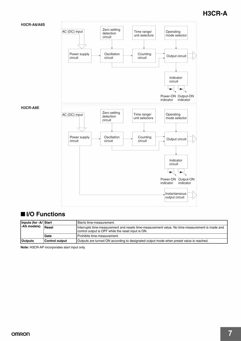
I/O Functions
Note: H3CR-AP incorporates start input only.
H3CR-A8/A8S
AC (DC) input
Output circuitPower supply circuit
Zero setting detection circuit
Oscillation circuit
Counting circuit
Time range/ unit selectors
Operating mode selector
Indicator circuit
Power-ON indicator
Output-ON indicator
H3CR-A8E
AC (DC) input
Output circuitPower supply circuit
Zero setting detection circuit
Oscillation circuit
Counting circuit
Time range/ unit selectors
Operating mode selector
Indicator circuit
Power-ON indicator
Output-ON indicator
Instantaneous output circuit
Inputs (for -A/-AS models)
Start Starts time-measurement.
Reset Interrupts time-measurement and resets time-measurement value. No time-measurement is made and control output is OFF while the reset input is ON.
Gate Prohibits time-measurement.
Outputs Control output Outputs are turned ON according to designated output mode when preset value is reached.
H3CR-A
8
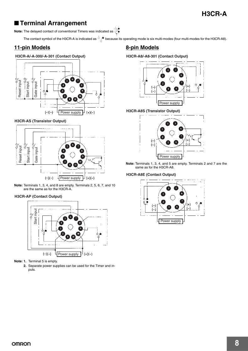
Terminal ArrangementNote: The delayed contact of conventional Timers was indicated as
The contact symbol of the H3CR-A is indicated as because its operating mode is six multi-modes (four multi-modes for the H3CR-A8).
11-pin Models
Note: Terminals 1, 3, 4, and 8 are empty. Terminals 2, 5, 6, 7, and 10are the same as for the H3CR-A.
Note: 1. Terminal 5 is empty.2. Separate power supplies can be used for the Timer and in-
puts.
8-pin Models
Note: Terminals 1, 3, 4, and 5 are empty. Terminals 2 and 7 are thesame as for the H3CR-A8.
H3CR-A/-A-300/-A-301 (Contact Output)
Res
et in
put
Sta
rt in
put
Gat
e in
put
Power supply
H3CR-AS (Transistor Output)
Power supply
Res
et in
put
Sta
rt in
put
Gat
e in
put
Power supply
Sta
rt in
put
H3CR-AP (Contact Output)
H3CR-A8/-A8-301 (Contact Output)
Power supply
H3CR-A8S (Transistor Output)
Power supply
H3CR-A8E (Contact Output)
Power supply
H3CR-A
9
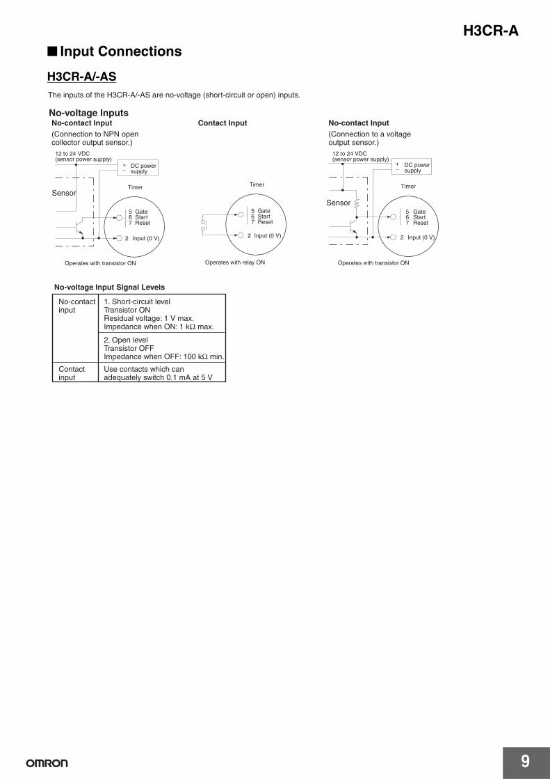
Input Connections
H3CR-A/-AS
567
2
+ −
567
2
+ −
567
2
The inputs of the H3CR-A/-AS are no-voltage (short-circuit or open) inputs.
No-voltage Input Signal Levels
No-contact Input Contact Input No-contact InputNo-voltage Inputs
SensorTimer
GateStartReset
Operates with transistor ON
Timer
Operates with relay ON
GateStartReset
Input (0 V)
Sensor
Timer
Operates with transistor ON
GateStartReset
Input (0 V)
(Connection to NPN open collector output sensor.)
12 to 24 VDC (sensor power supply)
DC power supply
Input (0 V)
No-contact input
1. Short-circuit level Transistor ONResidual voltage: 1 V max.Impedance when ON: 1 kΩ max.
2. Open level Transistor OFFImpedance when OFF: 100 kΩ min.
Contact input
Use contacts which can adequately switch 0.1 mA at 5 V
(Connection to a voltage output sensor.)
12 to 24 VDC (sensor power supply)
DC power supply
H3CR-A
10
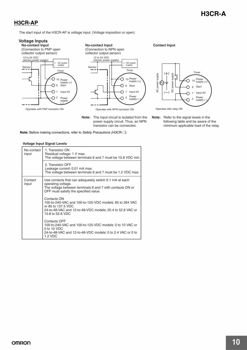
H3CR-AP
6
10
7
6
10
7
22
6
10
7
2
+ −
+ −
The start input of the H3CR-AP is voltage input. (Voltage imposition or open)
Voltage Input Signal Levels
No-contact Input No-contact Input Contact Input
SensorTimer
Start
Operates with PNP transistor ON Operates with NPN transistor ON
TimerSensor
Timer
Operates with relay ON
Voltage Inputs
Input 0V
Start
Input 0V
Start
Input 0VAC
pow
er s
uppl
y
DC
pow
er s
uppl
y
(Connection to PNP open collector output sensor)12 to 24 VDC (sensor power supply)
DC power supply
Power supply (+)
Power supply (−)
(Connection to NPN open collector output sensor)
12 to 24 VDC (sensor power supply)
DC power supply
Power supply (+)
Power supply (−)
Note: The input circuit is isolated from the power supply circuit. Thus, an NPN transistor can be connected.
Power supply (+)
Power supply (−)
Note: Refer to the signal levels in the following table and be aware of the minimum applicable load of the relay.
No-contact input
1. Transistor ONResidual voltage: 1 V max.The voltage between terminals 6 and 7 must be 10.8 VDC min.
2. Transistor OFFLeakage current: 0.01 mA max.The voltage between terminals 6 and 7 must be 1.2 VDC max.
Contact input
Use contacts that can adequately switch 0.1 mA at each operating voltage.The voltage between terminals 6 and 7 with contacts ON or OFF must satisfy the specified value.
Contacts ON100-to-240-VAC and 100-to-125-VDC models: 85 to 264 VAC or 85 to 137.5 VDC24-to-48-VAC and 12-to-48-VDC models: 20.4 to 52.8 VAC or 10.8 to 52.8 VDC
Contacts OFF100-to-240-VAC and 100-to-125-VDC models: 0 to 10 VAC or 0 to 10 VDC24-to-48-VAC and 12-to-48-VDC models: 0 to 2.4 VAC or 0 to 1.2 VDC
Note: Before making connections, refer to Safety Precautions (H3CR-@).
H3CR-A
11
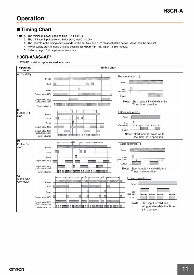
Operation
Timing Chart Note: 1. The minimum power-opening time (“Rt”) is 0.1 s.
2. The minimum input pulse width (for start, reset) is 0.05 s.3. The letter “t” in the timing charts stands for the set time and “t–a” means that the period is less than the time set.4. Power supply start in mode J is also possible for H3CR-A8/-A8E/-A8S/-A8-301 models.5. Refer to page 16 for application examples.
H3CR-A/-AS/-AP**H3CR-AP model incorporates start input only.
Operating mode
Timing chart
A: ON-delay
B:Flicker OFF start
B2:Flicker ON start
C:Signal ON/OFF-delay
t t
t
Power
Start
Reset
Output relay (NC)
Power indicator
Power
Output
Basic operation
Output relay (NO) (Output indicator)
Start(See note)
Note: Start input is invalid while the Timer is in operation.
t t t t
Basic operation
Power
Output
Power
Power indicator
Start
Reset
Output relay (NC)
Output relay (NO) (Output indicator)
Start(See note)
Note: Start input is invalid while the Timer is in operation.
t t t t
Basic operation
Power
Output
Power
Start
Reset
Power indicator
Output relay (NC)
Output relay (NO) (Output indicator)
Start(See note)
Note: Start input is invalid while the Timer is in operation.
tt t t
Basic operation
Power
Output
Power
Start
Reset
Output relay (NC)
Power indicator
Output relay (NO) (Output indicator)
Start(See note)
Note: Start input is valid and retriggerable while the Timer is in operation.

H3CR-A
12
Gate Signal Input
D:Signal OFF-delay
E: Interval
G:Signal ON/OFF-delay
J:One-shot output
Operating mode
Timing chart
t
Basic operation
Power
OutputOutput relay (NC)
Power indicator
Power
Start
Reset
Output relay (NO) (Output indicator)
Start(See note)
Note: Start input is valid and retriggerable while the Timer is in operation.
t
Power
Start
Reset
Output relay (NC)
Power indicator
Power
Output
Output relay (NO) (Output indicator)
Basic operation
Start(See note)
Note: Start input is valid and retriggerable while the Timer is in operation.
tttt
Basic operation
Power
Output
Power
Start
Reset
Output relay (NC)
Power indicator
Output relay (NO) (Output indicator)
Start(See note)
Note: Start input is valid and retriggerable while the Timer is in operation.
t
Basic operation
Output
Power
Power
Start
Reset
Output relay (NC)
Power indicator
Output relay (NO) (Output indicator)
1±0.6 s (Fixed)
1±0.6 s (Fixed)
Start (See note)
1±0.6 s (Fixed)
Note: Start input is valid and retriggerable while the Timer is in operation.(Previous start input will be cancelled.)
t1 t2
Power
Start
Gate
Reset
ON OFF
ON OFF
ON OFF
ON OFF
ON OFF
Output relay
Note: 1. This timing chart indicates the gate input in operating mode A (ON-delay operation).
2. The set time is the sum of t1 and t2.
3. H3CR-AP model incorporates start input only.
H3CR-A
13
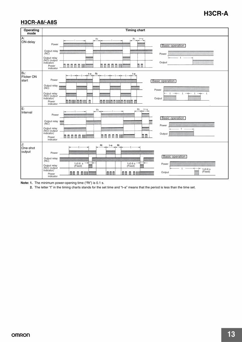
H3CR-A8/-A8S
Note: 1. The minimum power-opening time (“Rt”) is 0.1 s.2. The letter “t” in the timing charts stands for the set time and “t–a” means that the period is less than the time set.
Operating mode
Timing chart
A: ON-delay
B2:Flicker ON start
v
E: Interval
J:One-shot output
t
Power
Output
Basic operationPower
Output relay (NC)
Output relay (NO) (output indicator)
Power indicator
t t t t
Power
Power
Output
Basic operationOutput relay (NC)
Output relay (NO) (output indicator)
Power indicator
tPower
Output
Basic operationPower
Output relay (NC)
Output relay (NO) (output indicator)
Power indicator
t
Power
Power
Output
Basic operationOutput relay (NC)
Output relay (NO) (output indicator)
Power indicator
1±0.6 s (Fixed)
1±0.6 s (Fixed)
1±0.6 s (Fixed)
H3CR-A
14
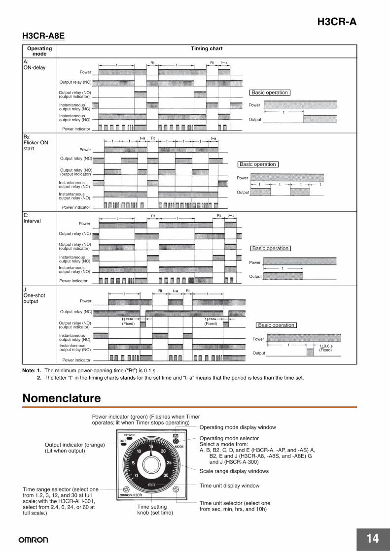
H3CR-A8E
Note: 1. The minimum power-opening time (“Rt”) is 0.1 s.2. The letter “t” in the timing charts stands for the set time and “t–a” means that the period is less than the time set.
Nomenclature
Operating mode
Timing chart
A: ON-delay
B2:Flicker ON start
E: Interval
J:One-shot output
t
Power
Power indicator
Power
Output
Basic operation
Output relay (NC)
Output relay (NO) (output indicator)
Instantaneous output relay (NC)
Instantaneous output relay (NO)
t t t t
Power
Power indicator
Power
Output
Basic operationOutput relay (NC)
Output relay (NO) (output indicator)
Instantaneous output relay (NC)
Instantaneous output relay (NO)
tPower
Output
Basic operation
Power
Power indicator
Output relay (NC)
Output relay (NO) (output indicator)
Instantaneous output relay (NC)
Instantaneous output relay (NO)
t
Power
Power indicator
Power
Output
Basic operation(Fixed) (Fixed)
Output relay (NC)
Output relay (NO) (output indicator)
Instantaneous output relay (NC)
Instantaneous output relay (NO)
1±0.6 s (Fixed)
Operating mode display window
Scale range display windows
Time unit display window
Power indicator (green) (Flashes when Timer operates; lit when Timer stops operating)
Output indicator (orange) (Lit when output)
Time range selector (select one from 1.2, 3, 12, and 30 at full scale; with the H3CR-A@-301, select from 2.4, 6, 24, or 60 at full scale.)
Time setting knob (set time)
Time unit selector (select one from sec, min, hrs, and 10h)
Operating mode selectorSelect a mode from:A, B, B2, C, D, and E (H3CR-A, -AP, and -AS) A,
B2, E and J (H3CR-A8, -A8S, and -A8E) G and J (H3CR-A-300)
H3CR-A
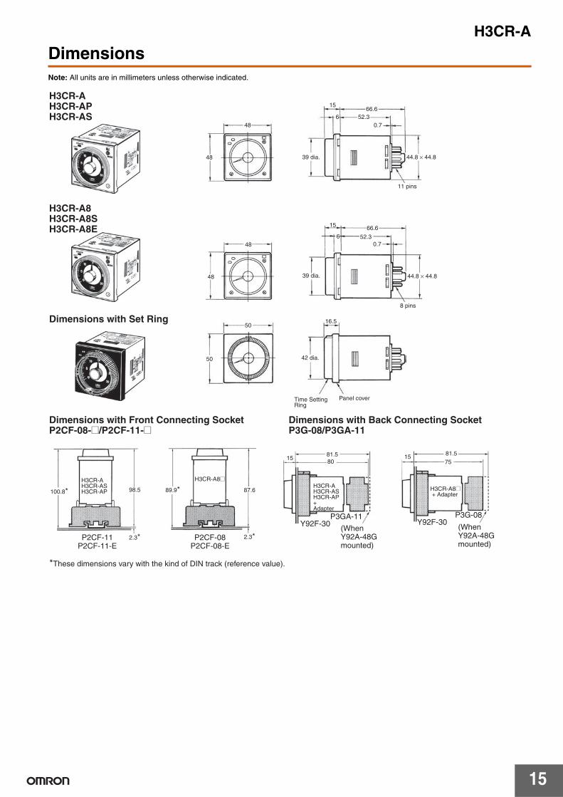
15
DimensionsNote: All units are in millimeters unless otherwise indicated.
48
48
66.652.3
15
6
44.8 × 44.8
0.7
48
66.6
48
15
6 52.30.7
44.8 × 44.8
11 pins
39 dia.
8 pins
39 dia.
H3CR-A H3CR-AP H3CR-AS
H3CR-A8 H3CR-A8S H3CR-A8E
5016.5
50
Dimensions with Set Ring
Panel cover
42 dia.
Time Setting Ring
100.8* 98.5
2.3*
89.9* 87.6
2.3*
8015 15
7581.5 81.5
*These dimensions vary with the kind of DIN track (reference value).
H3CR-A8@
Y92F-30P3GA-11
Y92F-30P3G-08
H3CR-A H3CR-AS H3CR-AP
P2CF-11P2CF-11-E
P2CF-08P2CF-08-E
H3CR-A H3CR-AS H3CR-AP + Adapter
(When Y92A-48G mounted)
H3CR-A8@ + Adapter
(When Y92A-48G mounted)
Dimensions with Front Connecting Socket P2CF-08-@/P2CF-11-@
Dimensions with Back Connecting Socket P3G-08/P3GA-11
H3CR-A
16
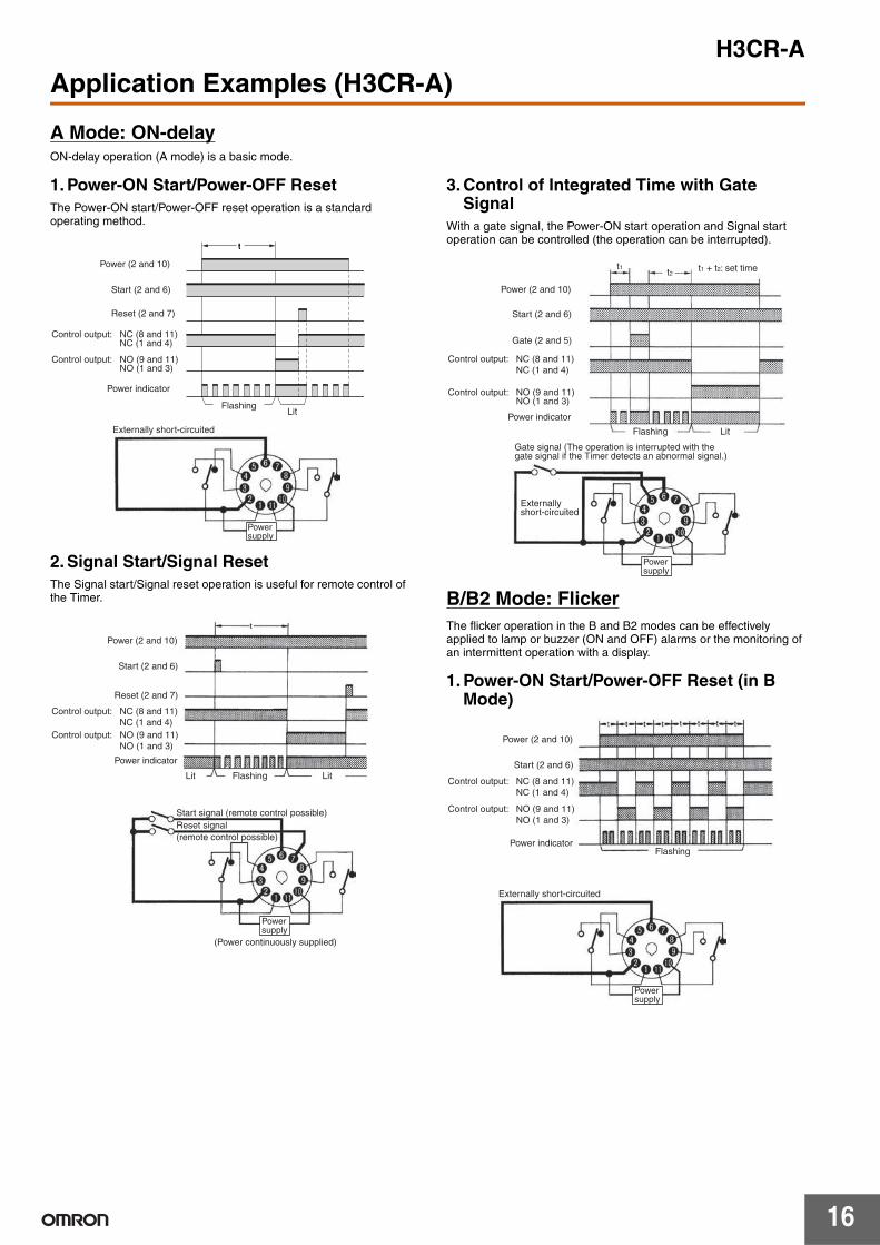
Application Examples (H3CR-A)
A Mode: ON-delayON-delay operation (A mode) is a basic mode.
1. Power-ON Start/Power-OFF ResetThe Power-ON start/Power-OFF reset operation is a standard operating method.
2. Signal Start/Signal ResetThe Signal start/Signal reset operation is useful for remote control of the Timer.
3. Control of Integrated Time with Gate Signal
With a gate signal, the Power-ON start operation and Signal start operation can be controlled (the operation can be interrupted).
B/B2 Mode: FlickerThe flicker operation in the B and B2 modes can be effectively applied to lamp or buzzer (ON and OFF) alarms or the monitoring of an intermittent operation with a display.
1. Power-ON Start/Power-OFF Reset (in B Mode)
t
Power (2 and 10)
Start (2 and 6)
Power indicator
FlashingLit
Externally short-circuited
Control output: NC (8 and 11) NC (1 and 4)
Control output: NO (9 and 11) NO (1 and 3)
Power supply
t
Reset (2 and 7)
Power (2 and 10)
Start (2 and 6)
Power indicator
Flashing Lit
Reset (2 and 7)
Lit
(Power continuously supplied)
Start signal (remote control possible)Reset signal (remote control possible)
Control output: NC (8 and 11) NC (1 and 4)
Control output: NO (9 and 11) NO (1 and 3)
Power supply
t1t2
Power (2 and 10)
Start (2 and 6)
Power indicator
Flashing Lit
Gate (2 and 5)
t1 + t2: set time
Control output: NC (8 and 11) NC (1 and 4)
Control output: NO (9 and 11) NO (1 and 3)
Gate signal (The operation is interrupted with the gate signal if the Timer detects an abnormal signal.)
Externally short-circuited
Power supply
Power (2 and 10)
Start (2 and 6)
Power indicatorFlashing
Externally short-circuited
Control output: NC (8 and 11) NC (1 and 4)
Power supply
Control output: NO (9 and 11) NO (1 and 3)
H3CR-A
17
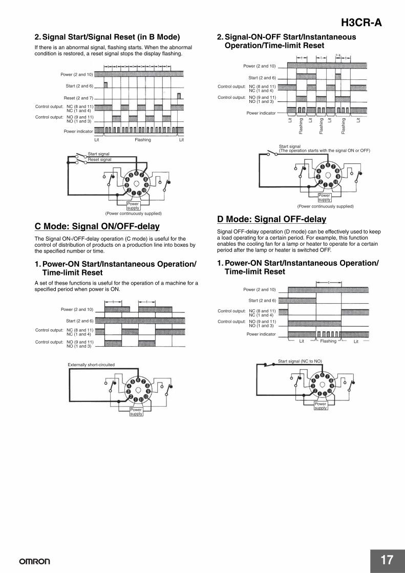
2. Signal Start/Signal Reset (in B Mode)If there is an abnormal signal, flashing starts. When the abnormal condition is restored, a reset signal stops the display flashing.
C Mode: Signal ON/OFF-delayThe Signal ON-/OFF-delay operation (C mode) is useful for the control of distribution of products on a production line into boxes by the specified number or time.
1. Power-ON Start/Instantaneous Operation/Time-limit Reset
A set of these functions is useful for the operation of a machine for a specified period when power is ON.
2. Signal-ON-OFF Start/Instantaneous Operation/Time-limit Reset
D Mode: Signal OFF-delaySignal OFF-delay operation (D mode) can be effectively used to keep a load operating for a certain period. For example, this function enables the cooling fan for a lamp or heater to operate for a certain period after the lamp or heater is switched OFF.
1. Power-ON Start/Instantaneous Operation/Time-limit Reset
Power (2 and 10)
Start (2 and 6)
Power indicator
Reset (2 and 7)
Lit Flashing Lit
(Power continuously supplied)
Start signalReset signal
Control output: NC (8 and 11) NC (1 and 4)
Control output: NO (9 and 11) NO (1 and 3)
Power supply
t t
Power (2 and 10)
Start (2 and 6)
Externally short-circuited
Control output: NC (8 and 11) NC (1 and 4)
Control output: NO (9 and 11) NO (1 and 3)
Power supply
Power (2 and 10)
Start (2 and 6)
Power indicator
Lit
Lit
Lit
Lit
(Power continuously supplied)
Fla
shin
g
Fla
shin
g
Fla
shin
g
Control output: NC (8 and 11) NC (1 and 4)
Control output: NO (9 and 11) NO (1 and 3)
Start signal (The operation starts with the signal ON or OFF)
Power supply
Power (2 and 10)
Start (2 and 6)
Power indicator
Lit Flashing Lit
Start signal (NC to NO)
Control output: NC (8 and 11) NC (1 and 4)
Control output: NO (9 and 11) NO (1 and 3)
Power supply

H3CR-A
18
2. Signal Start/Instantaneous Operation/Time-limit Reset
E Mode: Interval
1. Power-ON Start/Instantaneous Operation/Time-limit Reset
This function is useful for the operation of a machine for a specified period after power is ON.
2. Signal Start/Instantaneous Operation/Time-limit Reset
This function is useful for the repetitive control such as the filling of liquid for a specified period after each Signal start input.
Lit
Power (2 and 10)
Start (2 and 6)
Power indicator
Flashing Lit
Start signal (NO to NC to NO)
(Power continuously supplied)
Control output: NC (8 and 11) NC (1 and 4)
Control output: NO (9 and 11) NO (1 and 3)
Power supply
Power (2 and 10)
Start (2 and 6)
Externally short-circuited
Control output: NC (8 and 11) NC (1 and 4)
Control output: NO (9 and 11) NO (1 and 3)
Power supply
t t
Power (2 and 10)
Start (2 and 6)
Start signal
(Power continuously supplied)
Control output: NC (8 and 11) NC (1 and 4)
Control output: NO (9 and 11) NO (1 and 3)
Power supply
H3CR-A
19
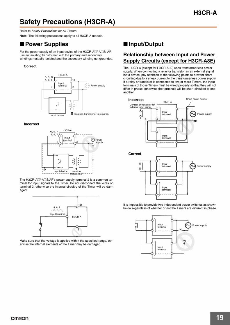
Safety Precautions (H3CR-A)Refer to Safety Precautions for All Timers.
Note: The following precautions apply to all H3CR-A models.
Power SuppliesFor the power supply of an input device of the H3CR-A@/-A@S/-AP, use an isolating transformer with the primary and secondary windings mutually isolated and the secondary winding not grounded.
The H3CR-A@/-A@S/AP’s power supply terminal 2 is a common ter-minal for input signals to the Timer. Do not disconnect the wires onterminal 2, otherwise the internal circuitry of the Timer will be dam-aged.
Make sure that the voltage is applied within the specified range, oth-erwise the internal elements of the Timer may be damaged.
Input/Output
Relationship between Input and Power Supply Circuits (except for H3CR-A8E)The H3CR-A (except for H3CR-A8E) uses transformerless power supply. When connecting a relay or transistor as an external signal input device, pay attention to the following points to prevent short-circuiting due to a sneak current to the transformerless power supply. If a relay or transistor is connected to two or more Timers, the input terminals of those Timers must be wired properly so that they will not differ in phase, otherwise the terminals will be short-circuited to one another.
It is impossible to provide two independent power switches as shown below regardless of whether or not the Timers are different in phase.
S,G, R5, 6, 7
2
10
2
H3CR-A
Power supply
Isolation transformer is required.Input device
Input terminal
Correct
H3CR-A
Power supply
Input terminal
Input device
10
22
Incorrect
Isolation transformer
S,G, R5, 6, 7
5, 6, 7G, S, R
10
2
H3CR-AInput terminal
Power supply
H3CR-A
Power supply
Incorrect
Correct
Short-circuit current
Contact or transistor for external input signal
Input terminal
Input terminal
Input terminal
Input terminal
Power supplyInput terminal
Input terminal

H3CR-A
20
Relationship between Input and Power Supply Circuits (H3CR-A@/-A@S)An appropriate input is applied to the input signal terminals of the H3CR-A@/-A@S when one of the input terminals is short-circuited with the common terminal (terminal 2) for the input signals. Never use terminal 10 as the common terminal for this purpose, otherwise the internal circuit of the Timer will be damaged.
Do not connect a relay or any other load between input terminals, otherwise the internal circuit of the Timer will be damaged due to the high-tension voltage applied to the input terminals.
Relationship between Input and Power Supply Circuits (H3CR-AP)
Since the input circuit and the power supply circuit are configured independently, the input circuit can be turned ON or OFF irrespective of the ON/OFF state of the power supply. It must be noted that a voltage equivalent to the power supply voltage is applied to the input circuit.
If a relay or transistor is connected to two or more Timers, the input terminals of those Timers must be wired properly so that they will not be different in phase or the terminals will be short-circuited to one another (refer to the figures below).
Common to All H3CR-A ModelsWith the H3CR-AP, input wires must be as short as possible. If the floating capacity of wires exceeds 1,200 pF (approx. 10 m for cables with 120 pF/m), the operation will be affected. Pay particular attention when using shielded cables.
The H3CR-A@S transistor output is isolated from the internal circuitry by a photocoupler. Therefore, either NPN or PNP output is possible.
10
2
5, 6, 7G, S, R
H3CR-A
Input terminal
Incorrect
AC or DC power supply
5, 6, 7G, S, R
10
2
Input terminal
Correct
H3CR-AAC or DC power supply
10
2
5, 6, 7G, S, R
Ry
H3CR-A
Input terminal
AC or DC power supply
Input contact
Input circuit
H3CR-AP
AC/DC power supply Power supply
circuit
106
7
2
10
6
7
2
Incorrect
H3CR-AP Power supply
H3CR-APShort-circuit current
Contact or transistor for external input signal
10
6
7
2
106
7
2
Correct
Power supplyH3CR-AP
H3CR-AP
Short-circuit current
Contact or transistor for external input signal
In the interest of product improvement, specifications are subject to change without notice.
ALL DIMENSIONS SHOWN ARE IN MILLIMETERS.
To convert millimeters into inches, multiply by 0.03937. To convert grams into ounces, multiply by 0.03527.
CSM_H3CR-Common_DS_E_1_1
1
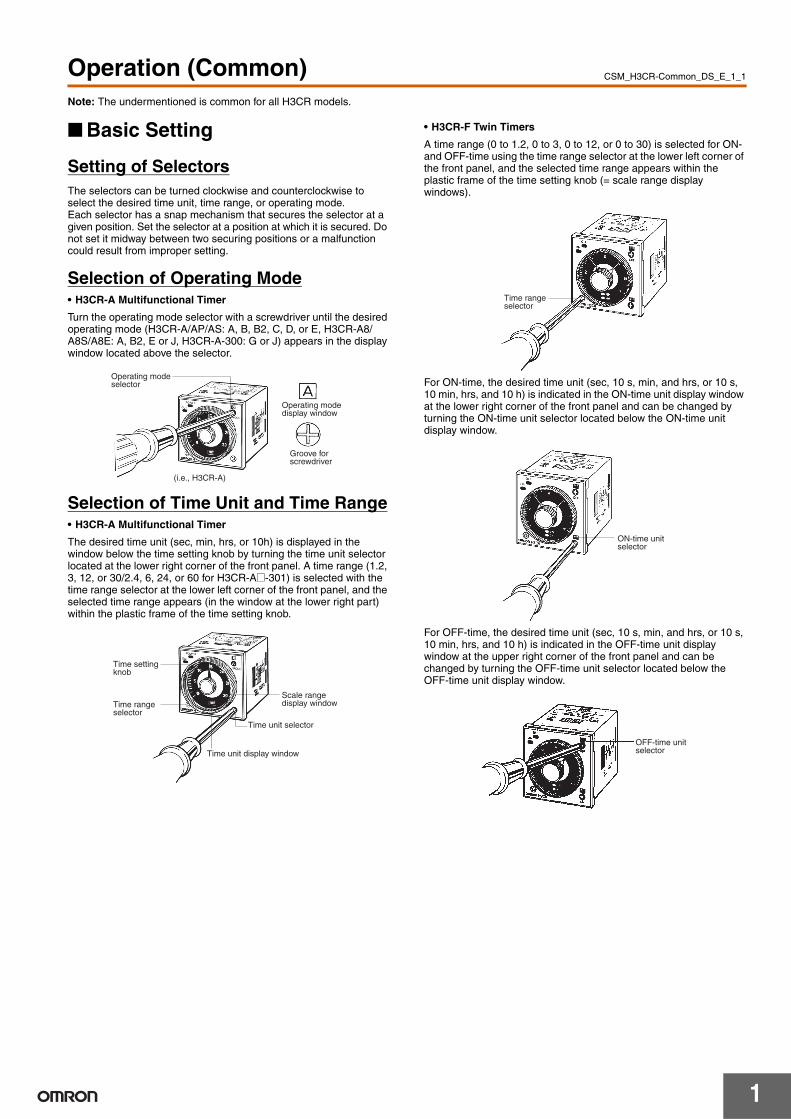
Operation (Common)Note: The undermentioned is common for all H3CR models.
Basic Setting
Setting of SelectorsThe selectors can be turned clockwise and counterclockwise to select the desired time unit, time range, or operating mode.Each selector has a snap mechanism that secures the selector at a given position. Set the selector at a position at which it is secured. Do not set it midway between two securing positions or a malfunction could result from improper setting.
Selection of Operating Mode• H3CR-A Multifunctional Timer
Turn the operating mode selector with a screwdriver until the desired operating mode (H3CR-A/AP/AS: A, B, B2, C, D, or E, H3CR-A8/A8S/A8E: A, B2, E or J, H3CR-A-300: G or J) appears in the display window located above the selector.
Selection of Time Unit and Time Range• H3CR-A Multifunctional Timer
The desired time unit (sec, min, hrs, or 10h) is displayed in the window below the time setting knob by turning the time unit selector located at the lower right corner of the front panel. A time range (1.2, 3, 12, or 30/2.4, 6, 24, or 60 for H3CR-A@-301) is selected with the time range selector at the lower left corner of the front panel, and the selected time range appears (in the window at the lower right part) within the plastic frame of the time setting knob.
• H3CR-F Twin Timers
A time range (0 to 1.2, 0 to 3, 0 to 12, or 0 to 30) is selected for ON- and OFF-time using the time range selector at the lower left corner of the front panel, and the selected time range appears within the plastic frame of the time setting knob (= scale range display windows).
For ON-time, the desired time unit (sec, 10 s, min, and hrs, or 10 s, 10 min, hrs, and 10 h) is indicated in the ON-time unit display window at the lower right corner of the front panel and can be changed by turning the ON-time unit selector located below the ON-time unit display window.
For OFF-time, the desired time unit (sec, 10 s, min, and hrs, or 10 s, 10 min, hrs, and 10 h) is indicated in the OFF-time unit display window at the upper right corner of the front panel and can be changed by turning the OFF-time unit selector located below the OFF-time unit display window.
(i.e., H3CR-A)
Operating mode selector
Operating mode display window
Groove for screwdriver
Time unit selector
Time unit display window
Time setting knob
Time range selector
Scale range display window
Time range selector
ON-time unit selector
OFF-time unit selector

H3CR
2
• H3CR-G Star-delta Timers
A star operation time range (0 to 6, 0 to 12, 0 to 60, or 0 to 120 seconds) is selected with the star operation time range selector at the lower left corner of the front panel.
The time required for switching (0.05, 0.1, 0.25, or 0.5 second) from the star operation to the delta operation of the H3CR-G can be selected with the star-delta transfer time selector at the lower right corner of the front panel.
• H3CR-H Power OFF-delay Timers
A time range (0 to 0.6, 0 to 1.2, 0 to 6, and 0 to 12) is selected with the time range selector at the lower left corner of the front panel. No time unit selector is available. When ordering the H3CR-H, specify S (for the second unit) or M (for the minute unit) for your H3CR-H.
Setting of TimeUse the time setting knob to set the desired time.
Using the Time Setting Ring for H3CR-A/-GSetting a Specific TimeMount the Panel Cover on the Timer, set the desired time with the time setting knob, and place Time Setting Ring A onto the time setting knob so that the time setting notch of Time Setting Ring A is in the center of the reset lock position of the Panel Cover.
Limiting the Setting RangeExample: To set a range of 10 and 20 s.Mount the Panel Cover on the Timer, set the time setting knob to 10 s (the lower limit of the setting range), and place Time Setting Ring C onto the time setting knob so that the stopper of Time Setting Ring C is on the right edge of the reset lock position of the Panel cover. Next, set the time setting knob to 20 s (the upper limit of the setting range), place Time Setting Ring B onto the time setting knob so that the stopper of Time Setting Ring B is on the left edge of the reset lock position of the Panel Cover.
Star operation time range selector
Star-delta transfer time selector
Time range selector
Reset lock position
Time Setting Ring A Panel cover
Example: To set the time to 10 s.
Time setting notch Setting position
Time setting notch
Stopper Reset lock position
Panel cover
Range
Time Setting Ring B
Time Setting Ring C
H3CR
3
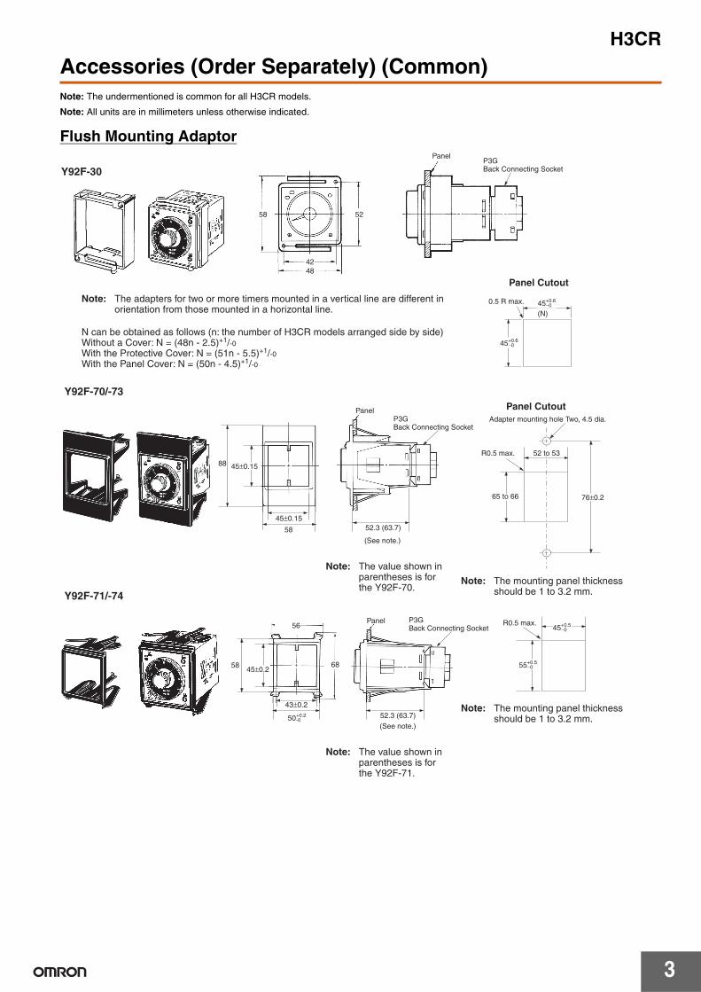
Accessories (Order Separately) (Common)Note: The undermentioned is common for all H3CR models.
Note: All units are in millimeters unless otherwise indicated.
Flush Mounting Adaptor
45+0.6−0
(N)
45+0.6−0
58 52
4248
Y92F-30
Panel Cutout
0.5 R max.
Panel
Note: The adapters for two or more timers mounted in a vertical line are different in orientation from those mounted in a horizontal line.
N can be obtained as follows (n: the number of H3CR models arranged side by side)Without a Cover: N = (48n - 2.5)+1/-0With the Protective Cover: N = (51n - 5.5)+1/-0With the Panel Cover: N = (50n - 4.5)+1/-0
P3GBack Connecting Socket
88
58
45±0.15
43±0.2
5845±0.2
50+0.2-0
56
68
76±0.2
45+0.5−0
55+0.5−0
45±0.15
52.3 (63.7)
52.3 (63.7)
Y92F-70/-73
Y92F-71/-74
Panel
Panel
Panel CutoutAdapter mounting hole Two, 4.5 dia.
52 to 53
65 to 66
R0.5 max.
R0.5 max.
Note: The mounting panel thickness should be 1 to 3.2 mm.
Note: The mounting panel thickness should be 1 to 3.2 mm.
P3GBack Connecting Socket
P3GBack Connecting Socket
Note: The value shown in parentheses is for the Y92F-70.
(See note.)
Note: The value shown in parentheses is for the Y92F-71.
(See note.)

H3CR
4
Track Mounting/Front Connecting Socket
Track Mounting/Front Connecting Socket
7.83 4.5
35.4
4
40±0.2
40±0.2
7.8
4
35.4
20.319
3
1.3
5 4.5
70 max.
50 max.20.3 max.
P2CF-08-E (Finger Safe Terminal Type)Conforming to VDE0106/P100
Surface Mounting Holes
Two, 4.5 dia. or two, M4
50 max.
70 max.
21.5 max.
P2CF-08Eight, M3.5 × 7.5 sems
Two, 4.5 dia. holes
Terminal Arrangement/Internal Connections (Top View)
Two, 4.5 dia. holes
Eight,M3.5 × 7.5 sems
40±0.2
7.83 4.5
35.4
4
7.8
440±0.2
35.4
30
5 4.5
3
1.2
Surface Mounting Holes
Two, 4.5 dia. or two, M4
70 max.
50 max.31.2 max.
P2CF-11-E (Finger Safe Terminal Type)Conforming to VDE0106/P100
70 max.
50 max.31.2 max.
P2CF-11Eleven,M3.5 × 7.5 sems
Terminal Arrangement/Internal Connections (Top View)
Two, 4.5 dia. holes
Eleven, M3.5 × 7.5 sems
H3CR
5
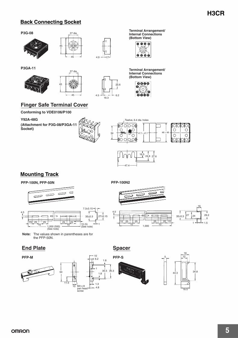
Back Connecting Socket
Mounting Track
45
45 4.9 17
45
45
25.6
4.516.3
6.2
34 47.7 × 47.7 48 × 48
47.4
16.524.6 27.6
27 dia.
P3GA-1127 dia.
Finger Safe Terminal CoverConforming to VDE0106/P100
Y92A-48G Twelve, 6.4 dia. holes
P3G-08Terminal Arrangement/Internal Connections (Bottom View)
Terminal Arrangement/Internal Connections (Bottom View)
(Attachment for P3G-08/P3GA-11 Socket)
4.5
15 25 25 25 2510 10
7.3±0.15
35±0.3 27±0.15
1
4.5
15 25 25 25 25 1510 10
35±0.3 27 24
16
29.2
1 1.51,000
PFP-100N2PFP-100N, PFP-50N
1,000 (500) (See note)
Note: The values shown in parentheses are for the PFP-50N.
15 (5) (See note)
50
11.5
106.2
1.8
135.5 35.3
1.8
1.34.8
5
1612
44.3 34.8
16.510
End Plate
PFP-M
M4 x 8 pan head screw
Spacer
PFP-S

H3CR
6
Protective CoverY92A-48BThe protective cover protects the front panel, particularly the time setting section, against dust, dirt, and water. It also prevents the set value from being altered due to accidental contact with the time setting knob.
Note: 1. The Y92A-48B Protective Cover is made of a hard plastic and therefore it must be removed to change the timer set value.
2. The Protective Cover cannot be mounted if the Panel Cover (sold separately) is used on the Timer.
Hold-down ClipHold-down clips are sold in sets of two.
Time Setting Ring/Panel Cover for H3CR-A/-GThere are three types of Panel Covers (Y92P-48GL, Y92P-48GB, and Y92P-48GM), all of which are available in three colors. Use the most suitable type of Panel Cover with the design of the scaling plate according to the application.When setting a given time for the Timer, use of the Y92S-27 or Y92S-28 Time Setting Ring facilitates the time setting operation and minimizes possible setting errors by operators.
The Y92F-73 or Y92-F-74 Flush Mounting Adapter or the Protective Cover cannot be used.
The Time Setting Ring and Panel Cover should be used as a pair.
Y92A-48B
Y92H-7/-1For PL08 and PL11 Sockets
Y92H-8/-2For PF085A Socket
Setting a specific time
Time Setting Ring A (Y92S-27) and Panel Cover (Y92P-48GL, -48GB, or -48GM)
Limiting the setting range
Time Setting Ring B or C (Y92S-28), and Panel Cover (Y92P-48GL, -48GB, or -48GM)
Y92S-27Time Setting A
Y92S-28Time Setting B
Y92S-28Time Setting C
Y92P-48GLLight Gray
Y92P-48GBBlack
Y92P-48GMMedium Gray
H3CR
7
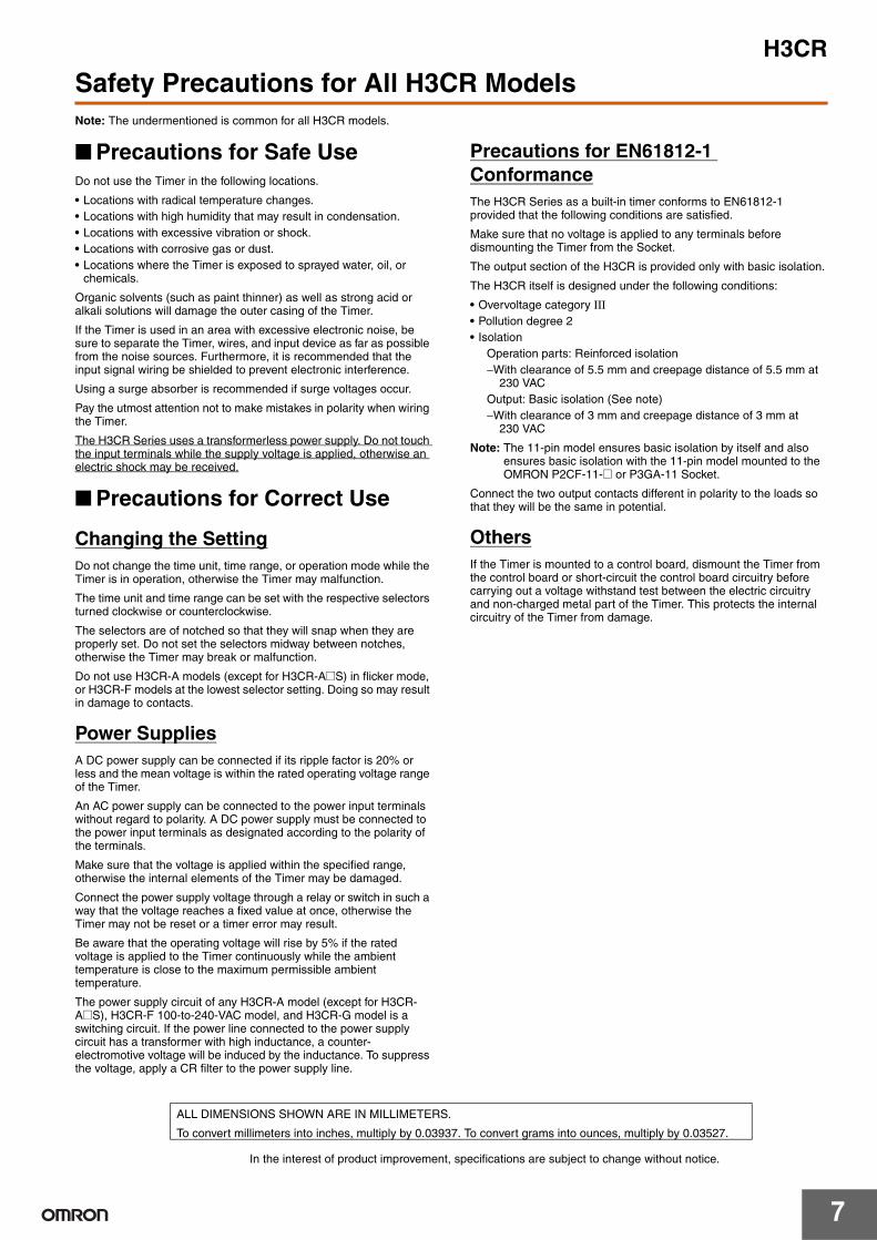
Safety Precautions for All H3CR ModelsNote: The undermentioned is common for all H3CR models.
Precautions for Safe UseDo not use the Timer in the following locations.
• Locations with radical temperature changes.• Locations with high humidity that may result in condensation.• Locations with excessive vibration or shock.• Locations with corrosive gas or dust.• Locations where the Timer is exposed to sprayed water, oil, or
chemicals.
Organic solvents (such as paint thinner) as well as strong acid or alkali solutions will damage the outer casing of the Timer.
If the Timer is used in an area with excessive electronic noise, be sure to separate the Timer, wires, and input device as far as possible from the noise sources. Furthermore, it is recommended that the input signal wiring be shielded to prevent electronic interference.
Using a surge absorber is recommended if surge voltages occur.
Pay the utmost attention not to make mistakes in polarity when wiring the Timer.
The H3CR Series uses a transformerless power supply. Do not touch the input terminals while the supply voltage is applied, otherwise an electric shock may be received.
Precautions for Correct Use
Changing the SettingDo not change the time unit, time range, or operation mode while the Timer is in operation, otherwise the Timer may malfunction.
The time unit and time range can be set with the respective selectors turned clockwise or counterclockwise.
The selectors are of notched so that they will snap when they are properly set. Do not set the selectors midway between notches, otherwise the Timer may break or malfunction.
Do not use H3CR-A models (except for H3CR-A@S) in flicker mode, or H3CR-F models at the lowest selector setting. Doing so may result in damage to contacts.
Power SuppliesA DC power supply can be connected if its ripple factor is 20% or less and the mean voltage is within the rated operating voltage range of the Timer.
An AC power supply can be connected to the power input terminals without regard to polarity. A DC power supply must be connected to the power input terminals as designated according to the polarity of the terminals.
Make sure that the voltage is applied within the specified range, otherwise the internal elements of the Timer may be damaged.
Connect the power supply voltage through a relay or switch in such a way that the voltage reaches a fixed value at once, otherwise the Timer may not be reset or a timer error may result.
Be aware that the operating voltage will rise by 5% if the rated voltage is applied to the Timer continuously while the ambient temperature is close to the maximum permissible ambient temperature.
The power supply circuit of any H3CR-A model (except for H3CR-A@S), H3CR-F 100-to-240-VAC model, and H3CR-G model is a switching circuit. If the power line connected to the power supply circuit has a transformer with high inductance, a counter-electromotive voltage will be induced by the inductance. To suppress the voltage, apply a CR filter to the power supply line.
Precautions for EN61812-1 ConformanceThe H3CR Series as a built-in timer conforms to EN61812-1 provided that the following conditions are satisfied.
Make sure that no voltage is applied to any terminals before dismounting the Timer from the Socket.
The output section of the H3CR is provided only with basic isolation.
The H3CR itself is designed under the following conditions:
• Overvoltage category III• Pollution degree 2• Isolation
Operation parts: Reinforced isolation−With clearance of 5.5 mm and creepage distance of 5.5 mm at
230 VACOutput: Basic isolation (See note)−With clearance of 3 mm and creepage distance of 3 mm at
230 VAC
Note: The 11-pin model ensures basic isolation by itself and also ensures basic isolation with the 11-pin model mounted to the OMRON P2CF-11-@ or P3GA-11 Socket.
Connect the two output contacts different in polarity to the loads so that they will be the same in potential.
OthersIf the Timer is mounted to a control board, dismount the Timer from the control board or short-circuit the control board circuitry before carrying out a voltage withstand test between the electric circuitry and non-charged metal part of the Timer. This protects the internal circuitry of the Timer from damage.
In the interest of product improvement, specifications are subject to change without notice.
ALL DIMENSIONS SHOWN ARE IN MILLIMETERS.
To convert millimeters into inches, multiply by 0.03937. To convert grams into ounces, multiply by 0.03527.

14
Read and Understand This CatalogPlease read and understand this catalog before purchasing the products. Please consult your OMRON representative if you have any questions orcomments.
Warranty and Limitations of Liability
WARRANTYOMRON's exclusive warranty is that the products are free from defects in materials and workmanship for a period of one year (or other period if specified)from date of sale by OMRON.
OMRON MAKES NO WARRANTY OR REPRESENTATION, EXPRESS OR IMPLIED, REGARDING NON-INFRINGEMENT, MERCHANTABILITY, ORFITNESS FOR PARTICULAR PURPOSE OF THE PRODUCTS. ANY BUYER OR USER ACKNOWLEDGES THAT THE BUYER OR USER ALONE HASDETERMINED THAT THE PRODUCTS WILL SUITABLY MEET THE REQUIREMENTS OF THEIR INTENDED USE. OMRON DISCLAIMS ALL OTHERWARRANTIES, EXPRESS OR IMPLIED.
LIMITATIONS OF LIABILITYOMRON SHALL NOT BE RESPONSIBLE FOR SPECIAL, INDIRECT, OR CONSEQUENTIAL DAMAGES, LOSS OF PROFITS OR COMMERCIAL LOSSIN ANY WAY CONNECTED WITH THE PRODUCTS, WHETHER SUCH CLAIM IS BASED ON CONTRACT, WARRANTY, NEGLIGENCE, OR STRICTLIABILITY.
In no event shall the responsibility of OMRON for any act exceed the individual price of the product on which liability is asserted.
IN NO EVENT SHALL OMRON BE RESPONSIBLE FOR WARRANTY, REPAIR, OR OTHER CLAIMS REGARDING THE PRODUCTS UNLESSOMRON'S ANALYSIS CONFIRMS THAT THE PRODUCTS WERE PROPERLY HANDLED, STORED, INSTALLED, AND MAINTAINED AND NOTSUBJECT TO CONTAMINATION, ABUSE, MISUSE, OR INAPPROPRIATE MODIFICATION OR REPAIR.
Application Considerations
SUITABILITY FOR USEOMRON shall not be responsible for conformity with any standards, codes, or regulations that apply to the combination of products in the customer'sapplication or use of the products.
At the customer's request, OMRON will provide applicable third party certification documents identifying ratings and limitations of use that apply to theproducts. This information by itself is not sufficient for a complete determination of the suitability of the products in combination with the end product,machine, system, or other application or use.
The following are some examples of applications for which particular attention must be given. This is not intended to be an exhaustive list of all possibleuses of the products, nor is it intended to imply that the uses listed may be suitable for the products:
• Outdoor use, uses involving potential chemical contamination or electrical interference, or conditions or uses not described in this catalog.
• Nuclear energy control systems, combustion systems, railroad systems, aviation systems, medical equipment, amusement machines, vehicles,safety equipment, and installations subject to separate industry or government regulations.
• Systems, machines, and equipment that could present a risk to life or property.
Please know and observe all prohibitions of use applicable to the products.
NEVER USE THE PRODUCTS FOR AN APPLICATION INVOLVING SERIOUS RISK TO LIFE OR PROPERTY WITHOUT ENSURING THAT THESYSTEM AS A WHOLE HAS BEEN DESIGNED TO ADDRESS THE RISKS, AND THAT THE OMRON PRODUCTS ARE PROPERLY RATED ANDINSTALLED FOR THE INTENDED USE WITHIN THE OVERALL EQUIPMENT OR SYSTEM.
PROGRAMMABLE PRODUCTSOMRON shall not be responsible for the user's programming of a programmable product, or any consequence thereof.
Disclaimers
CHANGE IN SPECIFICATIONSProduct specifications and accessories may be changed at any time based on improvements and other reasons.
It is our practice to change model numbers when published ratings or features are changed, or when significant construction changes are made.However, some specifications of the products may be changed without any notice. When in doubt, special model numbers may be assigned to fix orestablish key specifications for your application on your request. Please consult with your OMRON representative at any time to confirm actualspecifications of purchased products.
DIMENSIONS AND WEIGHTSDimensions and weights are nominal and are not to be used for manufacturing purposes, even when tolerances are shown.
PERFORMANCE DATAPerformance data given in this catalog is provided as a guide for the user in determining suitability and does not constitute a warranty. It may represent theresult of OMRON’s test conditions, and the users must correlate it to actual application requirements. Actual performance is subject to the OMRONWarranty and Limitations of Liability.
ERRORS AND OMISSIONSThe information in this document has been carefully checked and is believed to be accurate; however, no responsibility is assumed for clerical,typographical, or proofreading errors, or omissions.
2010.1In the interest of product improvement, specifications are subject to change without notice.
OMRON CorporationIndustrial Automation Companyhttp://www.ia.omron.com/
(c)Copyright OMRON Corporation 2010 All Right Reserved.

CSM_H3CR-A_DS_E_6_1 02/10 Note: Specifications are subject to change. © 2010 Omron Electronics LLC
OMRON CANADA, INC. • HEAD OFFICEToronto, ON, Canada • 416.286.6465 • 866.986.6766www.omron247.com
OMRON ELETRÔNICA DO BRASIL LTDA • HEAD OFFICESão Paulo, SP, Brasil • 55.11.2101.6300 • www.omron.com.br
OMRON ELECTRONICS MEXICO SA DE CV • HEAD OFFICEApodaca, N.L. • 52.811.156.99.10 • 001.800.556.6766 • [email protected]
OMRON ARGENTINA • SALES OFFICECono Sur • 54.11.4783.5300
OMRON CHILE • SALES OFFICESantiago • 56.9.9917.3920
OTHER OMRON LATIN AMERICA SALES54.11.4783.5300
OMRON ELECTRONICS LLC • THE AMERICAS HEADQUARTERS • Schaumburg, IL USA • 847.843.7900 • 800.556.6766 • www.omron247.com
OMRON EUROpE B.V. Wegalaan 67-69, NL-2132 JD, Hoofddorp, The Netherlands. Tel: +31 (0) 23 568 13 00 Fax: +31 (0) 23 568 13 88 www.industrial.omron.eu