solid dielectric, three phase reclosers providing ... · g&w electric page 3 control...
TRANSCRIPT

Solid Dielectric, Three Phase ReclosersProviding electronic three phase overcurrent protection for systems rated through 38kV, 800A continuous current, 12.5kA symmetrical interrupting
• Reliable performance• Control flexibility including SEL-351 series, SEL-651R2, GE controls and more• Operator safety with mechanical block• Maintenance-free operation• Overhead, substation and dead-front padmount designs• Ease of installation• Three internal current transformers• Up to six internal voltage sensors• Smart Grid/Lazer® solutions• RUS accepted
Catalog O-vs19
G & W E L E C T R I C P A G E 2
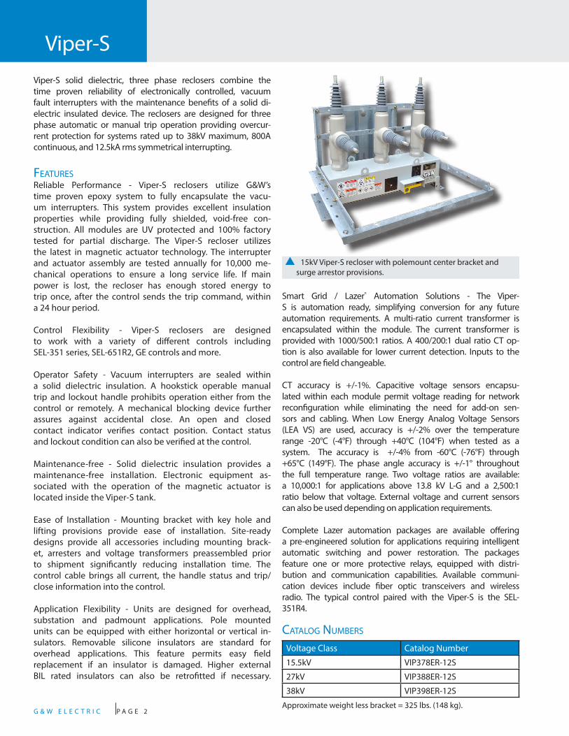
Viper-SViper-S solid dielectric, three phase reclosers combine the time proven reliability of electronically controlled, vacuum fault interrupters with the maintenance benefits of a solid di-electric insulated device. The reclosers are designed for three phase automatic or manual trip operation providing overcur-rent protection for systems rated up to 38kV maximum, 800A continuous, and 12.5kA rms symmetrical interrupting.
FeaturesReliable Performance - Viper-S reclosers utilize G&W’s time proven epoxy system to fully encapsulate the vacu-um interrupters. This system provides excellent insulation properties while providing fully shielded, void-free con-struction. All modules are UV protected and 100% factory tested for partial discharge. The Viper-S recloser utilizes the latest in magnetic actuator technology. The interrupter and actuator assembly are tested annually for 10,000 me-chanical operations to ensure a long service life. If main power is lost, the recloser has enough stored energy to trip once, after the control sends the trip command, within a 24 hour period.
Control Flexibility - Viper-S reclosers are designed to work with a variety of different controls including SEL-351 series, SEL-651R2, GE controls and more.
Operator Safety - Vacuum interrupters are sealed within a solid dielectric insulation. A hookstick operable manual trip and lockout handle prohibits operation either from the control or remotely. A mechanical blocking device further assures against accidental close. An open and closed contact indicator verifies contact position. Contact status and lockout condition can also be verified at the control.
Maintenance-free - Solid dielectric insulation provides a maintenance-free installation. Electronic equipment as-sociated with the operation of the magnetic actuator is located inside the Viper-S tank.
Ease of Installation - Mounting bracket with key hole and lifting provisions provide ease of installation. Site-ready designs provide all accessories including mounting brack-et, arresters and voltage transformers preassembled prior to shipment significantly reducing installation time. The control cable brings all current, the handle status and trip/close information into the control.
Application Flexibility - Units are designed for overhead, substation and padmount applications. Pole mounted units can be equipped with either horizontal or vertical in-sulators. Removable silicone insulators are standard for overhead applications. This feature permits easy field replacement if an insulator is damaged. Higher external BIL rated insulators can also be retrofitted if necessary.
Smart Grid / Lazer® Automation Solutions - The Viper-S is automation ready, simplifying conversion for any future automation requirements. A multi-ratio current transformer is encapsulated within the module. The current transformer is provided with 1000/500:1 ratios. A 400/200:1 dual ratio CT op-tion is also available for lower current detection. Inputs to the control are field changeable.
CT accuracy is +/-1%. Capacitive voltage sensors encapsu-lated within each module permit voltage reading for network reconfiguration while eliminating the need for add-on sen-sors and cabling. When Low Energy Analog Voltage Sensors (LEA VS) are used, accuracy is +/-2% over the temperature range -20°C (-4°F) through +40°C (104°F) when tested as a system. The accuracy is +/-4% from -60°C (-76°F) through +65°C (149°F). The phase angle accuracy is +/-1° throughout the full temperature range. Two voltage ratios are available: a 10,000:1 for applications above 13.8 kV L-G and a 2,500:1 ratio below that voltage. External voltage and current sensors can also be used depending on application requirements.
Complete Lazer automation packages are available offering a pre-engineered solution for applications requiring intelligent automatic switching and power restoration. The packages feature one or more protective relays, equipped with distri-bution and communication capabilities. Available communi-cation devices include fiber optic transceivers and wireless radio. The typical control paired with the Viper-S is the SEL-351R4.
p 15kV Viper-S recloser with polemount center bracket and surge arrestor provisions.
Catalog Numbers
Voltage Class Catalog Number
15.5kV VIP378ER-12S
27kV VIP388ER-12S
38kV VIP398ER-12S
Approximate weight less bracket = 325 lbs. (148 kg).
G & W E L E C T R I C P A G E 3
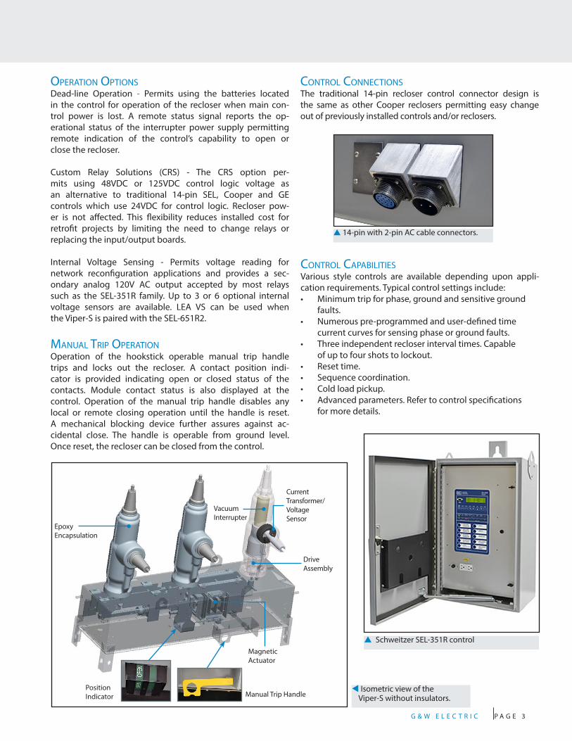
CoNtrol CoNNeCtioNsThe traditional 14-pin recloser control connector design is the same as other Cooper reclosers permitting easy change out of previously installed controls and/or reclosers.
operatioN optioNsDead-line Operation - Permits using the batteries located in the control for operation of the recloser when main con-trol power is lost. A remote status signal reports the op-erational status of the interrupter power supply permitting remote indication of the control’s capability to open or close the recloser.
Custom Relay Solutions (CRS) - The CRS option per-mits using 48VDC or 125VDC control logic voltage as an alternative to traditional 14-pin SEL, Cooper and GE controls which use 24VDC for control logic. Recloser pow-er is not affected. This flexibility reduces installed cost for retrofit projects by limiting the need to change relays or replacing the input/output boards.
Internal Voltage Sensing - Permits voltage reading for network reconfiguration applications and provides a sec-ondary analog 120V AC output accepted by most relays such as the SEL-351R family. Up to 3 or 6 optional internal voltage sensors are available. LEA VS can be used when the Viper-S is paired with the SEL-651R2.
maNual trip operatioNOperation of the hookstick operable manual trip handle trips and locks out the recloser. A contact position indi-cator is provided indicating open or closed status of the contacts. Module contact status is also displayed at the control. Operation of the manual trip handle disables any local or remote closing operation until the handle is reset. A mechanical blocking device further assures against ac-cidental close. The handle is operable from ground level. Once reset, the recloser can be closed from the control.
p Schweitzer SEL-351R control
CoNtrol CapabilitiesVarious style controls are available depending upon appli-cation requirements. Typical control settings include:• Minimum trip for phase, ground and sensitive ground
faults.• Numerous pre-programmed and user-defined time
current curves for sensing phase or ground faults.• Three independent recloser interval times. Capable
of up to four shots to lockout.• Reset time.• Sequence coordination. • Cold load pickup. • Advanced parameters. Refer to control specifications
for more details.
▲ 14-pin with 2-pin AC cable connectors.
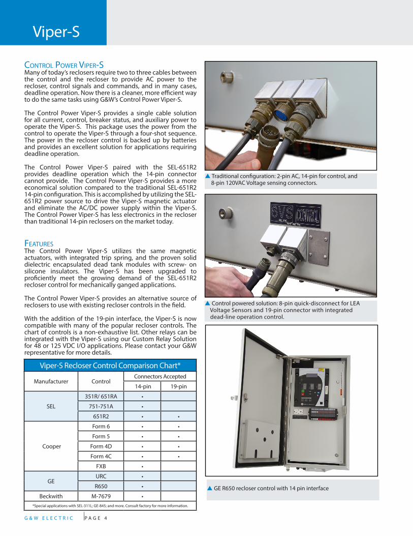
t Isometric view of the Viper-S without insulators.
Epoxy Encapsulation
Vacuum Interrupter
Drive Assembly
Magnetic Actuator
Current Transformer/ Voltage Sensor
Manual Trip HandlePosition Indicator
G & W E L E C T R I C P A G E 4
Viper-S
CoNtrol power Viper-sMany of today’s reclosers require two to three cables between the control and the recloser to provide AC power to the recloser, control signals and commands, and in many cases, deadline operation. Now there is a cleaner, more efficient way to do the same tasks using G&W’s Control Power Viper-S.
The Control Power Viper-S provides a single cable solution for all current, control, breaker status, and auxiliary power to operate the Viper-S. This package uses the power from the control to operate the Viper-S through a four-shot sequence. The power in the recloser control is backed up by batteries and provides an excellent solution for applications requiring deadline operation.
The Control Power Viper-S paired with the SEL-651R2 provides deadline operation which the 14-pin connector cannot provide. The Control Power Viper-S provides a more economical solution compared to the traditional SEL-651R2 14-pin configuration. This is accomplished by utilizing the SEL-651R2 power source to drive the Viper-S magnetic actuator and eliminate the AC/DC power supply within the Viper-S. The Control Power Viper-S has less electronics in the recloser than traditional 14-pin reclosers on the market today.
FeaturesThe Control Power Viper-S utilizes the same magnetic actuators, with integrated trip spring, and the proven solid dielectric encapsulated dead tank modules with screw- on silicone insulators. The Viper-S has been upgraded to proficiently meet the growing demand of the SEL-651R2 recloser control for mechanically ganged applications.
The Control Power Viper-S provides an alternative source of reclosers to use with existing recloser controls in the field.
With the addition of the 19-pin interface, the Viper-S is now compatible with many of the popular recloser controls. The chart of controls is a non-exhaustive list. Other relays can be integrated with the Viper-S using our Custom Relay Solution for 48 or 125 VDC I/O applications. Please contact your G&W representative for more details.
Viper-S Recloser Control Comparison Chart*
Manufacturer ControlConnectors Accepted
14-pin 19-pin
SEL
351R/ 651RA •
751-751A •
651R2 • •
Cooper
Form 6 • •
Form 5 • •
Form 4D • •
Form 4C • •
FXB •
GEURC •
R650 •
Beckwith M-7679 •*Special applications with SEL-311L; GE-845; and more. Consult factory for more information.
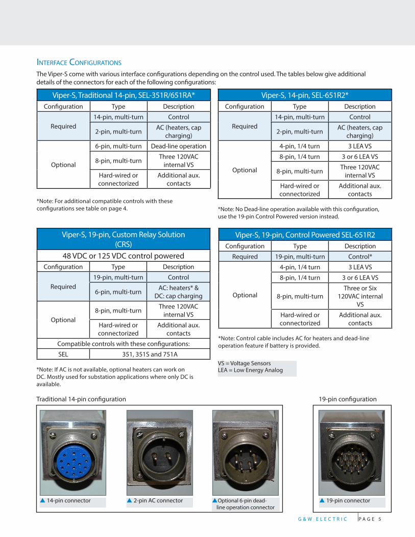
p Traditional configuration: 2-pin AC, 14-pin for control, and 8-pin 120VAC Voltage sensing connectors.
p Control powered solution: 8-pin quick-disconnect for LEA Voltage Sensors and 19-pin connector with integrated dead-line operation control.
p GE R650 recloser control with 14 pin interface
G & W E L E C T R I C P A G E 5
Viper-S, Traditional 14-pin, SEL-351R/651RA*Configuration Type Description
Required14-pin, multi-turn Control
2-pin, multi-turn AC (heaters, cap charging)
Optional
6-pin, multi-turn Dead-line operation
8-pin, multi-turn Three 120VAC internal VS
Hard-wired or connectorized
Additional aux. contacts
*Note: For additional compatible controls with these configurations see table on page 4.
iNterFaCe CoNFiguratioNs
Viper-S, 14-pin, SEL-651R2*Configuration Type Description
Required14-pin, multi-turn Control
2-pin, multi-turn AC (heaters, cap charging)
Optional
4-pin, 1/4 turn 3 LEA VS
8-pin, 1/4 turn 3 or 6 LEA VS
8-pin, multi-turn Three 120VAC internal VS
Hard-wired or connectorized
Additional aux. contacts
*Note: No Dead-line operation available with this configuration, use the 19-pin Control Powered version instead.
Viper-S, 19-pin, Custom Relay Solution (CRS)
48 VDC or 125 VDC control poweredConfiguration Type Description
Required19-pin, multi-turn Control
6-pin, multi-turn AC: heaters* & DC: cap charging
Optional8-pin, multi-turn Three 120VAC
internal VS
Hard-wired or connectorized
Additional aux. contacts
Compatible controls with these configurations:
SEL 351, 351S and 751A
*Note: If AC is not available, optional heaters can work on DC. Mostly used for substation applications where only DC is available.
Viper-S, 19-pin, Control Powered SEL-651R2Configuration Type Description
Required 19-pin, multi-turn Control*
Optional
4-pin, 1/4 turn 3 LEA VS
8-pin, 1/4 turn 3 or 6 LEA VS
8-pin, multi-turnThree or Six
120VAC internal VS
Hard-wired or connectorized
Additional aux. contacts
*Note: Control cable includes AC for heaters and dead-line operation feature if battery is provided.
p 14-pin connector p 2-pin AC connector pOptional 6-pin dead- line operation connector
p 19-pin connector
VS = Voltage SensorsLEA = Low Energy Analog
Traditional 14-pin configuration 19-pin configuration
The Viper-S come with various interface configurations depending on the control used. The tables below give additional details of the connectors for each of the following configurations:

G & W E L E C T R I C P A G E 6
Approx. Dimensions*- ins. (mm)
15.5kV 27kV 38kV
A 42 (1067) 47 (1204) 51 (1295)
B 39 (991) 44 (1118) 48 (1219)
Insulator FlexibilityPolemounted units can be equipped with either horizontal or vertical insula-tors. Removable silicone insulators are standard for overhead applications. This feature permits easy field replacement if an insulator is damaged. Higher exter-nal BIL rated insulators can also be ret-rofitted if necessary. 3 or 6 internal VS are available in either L or Z modules.
Polemount Center Bracket*
Polemount Alley-Arm*Horizontal Side Mounting Brackets with “Z” modules are ideal for overhead configurations where all three phase conductors are on one side of the pole.
Approx. Dimensions*- ins. (mm)
15.5kV 27kV 38kV
A 42 (1067) 50 (1270) 58 (1473)
35”(899mm)
p Shown with horizontal insulator configuration (Z module)
Viper-S
15.5"(394mm)
15.5"(394mm)
49"(1245mm)
A
B
Provisions for Lightning Arresters
A
* Dimensions are approximate. Do not use for construction. Galvanized steel bracket is standard. Stainless steel is available.
G & W E L E C T R I C P A G E 7
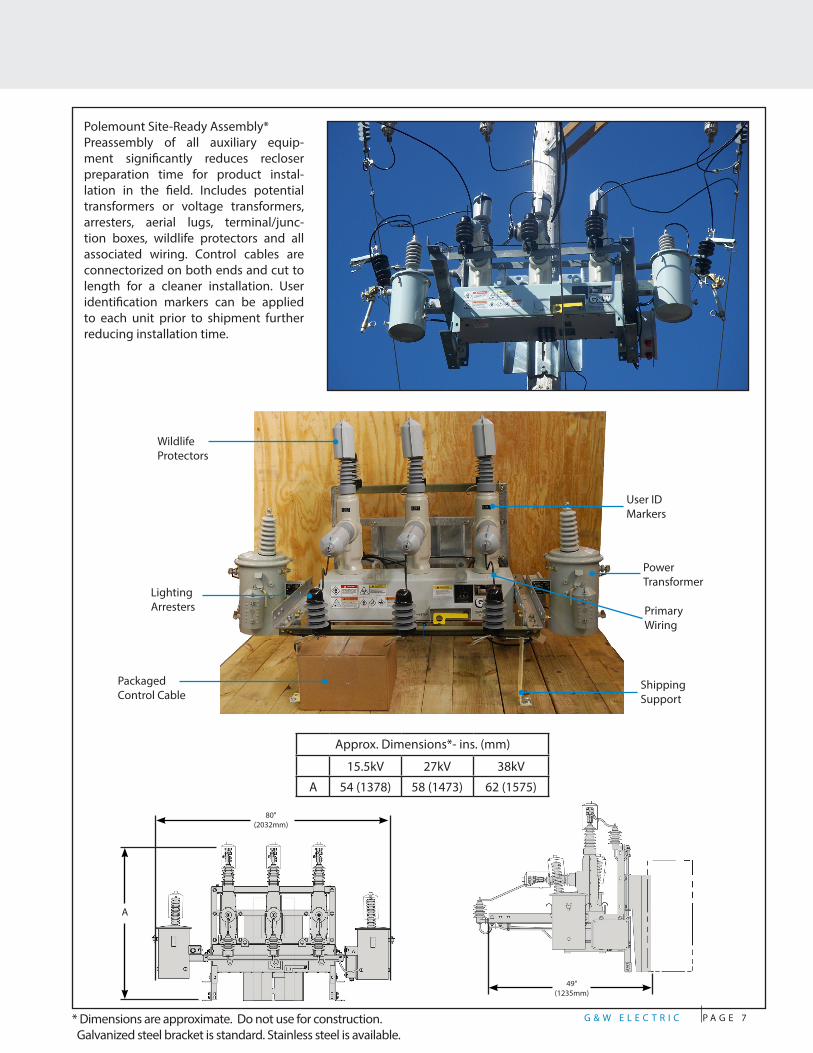
Polemount Site-Ready Assembly*Preassembly of all auxiliary equip-ment significantly reduces recloser preparation time for product instal-lation in the field. Includes potential transformers or voltage transformers, arresters, aerial lugs, terminal/junc-tion boxes, wildlife protectors and all associated wiring. Control cables are connectorized on both ends and cut to length for a cleaner installation. User identification markers can be applied to each unit prior to shipment further reducing installation time.
User ID Markers
Primary Wiring
Shipping Support
PowerTransformer
Wildlife Protectors
Packaged Control Cable
Lighting Arresters
Approx. Dimensions*- ins. (mm)
15.5kV 27kV 38kV
A 54 (1378) 58 (1473) 62 (1575)
80"(2032mm)
A
49"(1235mm)
* Dimensions are approximate. Do not use for construction. Galvanized steel bracket is standard. Stainless steel is available.
G & W E L E C T R I C P A G E 8
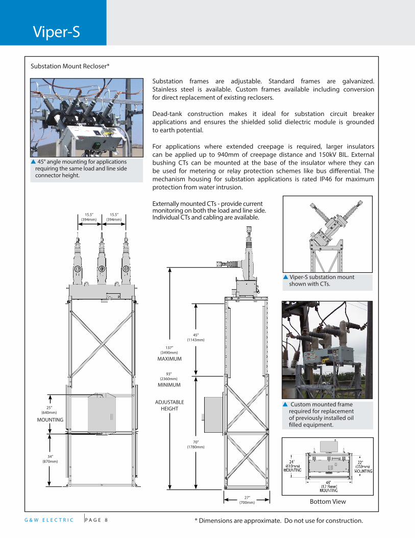
Substation Mount Recloser*
Substation frames are adjustable. Standard frames are galvanized. Stainless steel is available. Custom frames available including conversion for direct replacement of existing reclosers.
Dead-tank construction makes it ideal for substation circuit breaker applications and ensures the shielded solid dielectric module is grounded to earth potential.
For applications where extended creepage is required, larger insulators can be applied up to 940mm of creepage distance and 150kV BIL. External bushing CTs can be mounted at the base of the insulator where they can be used for metering or relay protection schemes like bus differential. The mechanism housing for substation applications is rated IP46 for maximum protection from water intrusion.
p Custom mounted frame required for replacement of previously installed oil filled equipment.
Bottom View
Viper-S
p 45° angle mounting for applications requiring the same load and line side connector height.
* Dimensions are approximate. Do not use for construction.
p Viper-S substation mount shown with CTs.
15.5”(394mm)
15.5”(394mm)
25”(640mm)
34”(870mm)
MOUNTING
137”(3490mm)
MAXIMUM
45”(1143mm)
93”(2360mm)
70”(1780mm)
27”(700mm)
MINIMUM
ADJUSTABLEHEIGHT
Externally mounted CTs - provide current monitoring on both the load and line side. Individual CTs and cabling are available.
G & W E L E C T R I C P A G E 9* Dimensions are approximate. Do not use for construction.
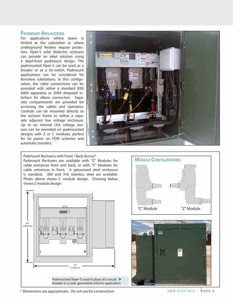
Padmount Reclosers with Front / Back Access*Padmount Reclosers are available with "Z" Modules for cable entrances front and back, or with "C" Modules for cable entrances in front. A galvanized steel enclosure is standard. 304 and 316 stainless steel are available. Photo above shows C module design. Drawing below shows Z module design.
padmouNt appliCatioNsFor applications where space is limited at the substation or where underground feeders require protec-tion, Viper-S solid dielectric reclosers can provide an ideal solution using a dead-front padmount design. The padmounted Viper-S can be used as a breaker or as a tie-switch. Padmount applications can be considered for fenceless substations. In this configu-ration, the cable connections can be provided with either a standard IEEE 600A apparatus or 200A deepwell in-terface for elbow connectors. Sepa-rate compartments are provided for accessing the cables and operators. Controls can be mounted directly to the recloser frame or within a sepa-rate adjacent low voltage enclosure. Up to six internal LEA voltage sen-sors can be provided on padmounted designs with Z or C modules, perfect for tie points on FDIR schemes and automatic transfers.
module CoNFiguratioNs
“C” Module “Z” Module
53”(1345mm)
64”(1626mm)
Padmounted Viper-S used in place of a circuit u breaker in a solar generation intertie application
G & W E L E C T R I C P A G E 1 0
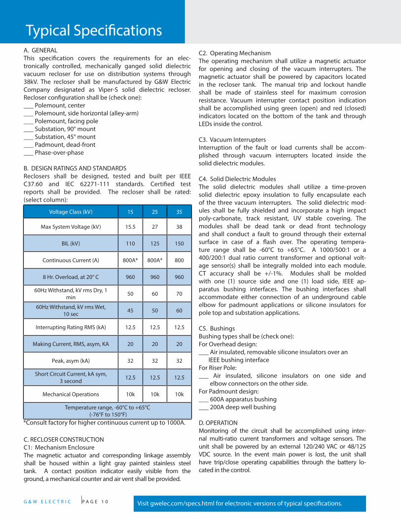
Typical SpecificationsA. GENERALThis specification covers the requirements for an elec-tronically controlled, mechanically ganged solid dielectric vacuum recloser for use on distribution systems through 38kV. The recloser shall be manufactured by G&W Electric Company designated as Viper-S solid dielectric recloser. Recloser configuration shall be (check one):___ Polemount, center___ Polemount, side horizontal (alley-arm)___ Polemount, facing pole___ Substation, 90° mount___ Substation, 45° mount___ Padmount, dead-front___ Phase-over-phase
B. DESIGN RATINGS AND STANDARDSReclosers shall be designed, tested and built per IEEE C37.60 and IEC 62271-111 standards. Certified test reports shall be provided. The recloser shall be rated: (select column):
C2. Operating MechanismThe operating mechanism shall utilize a magnetic actuator for opening and closing of the vacuum interrupters. The magnetic actuator shall be powered by capacitors located in the recloser tank. The manual trip and lockout handle shall be made of stainless steel for maximum corrosion resistance. Vacuum interrupter contact position indication shall be accomplished using green (open) and red (closed) indicators located on the bottom of the tank and through LEDs inside the control.
C3. Vacuum InterruptersInterruption of the fault or load currents shall be accom-plished through vacuum interrupters located inside the solid dielectric modules.
C4. Solid Dielectric ModulesThe solid dielectric modules shall utilize a time-proven solid dielectric epoxy insulation to fully encapsulate each of the three vacuum interrupters. The solid dielectric mod-ules shall be fully shielded and incorporate a high impact poly-carbonate, track resistant, UV stable covering. The modules shall be dead tank or dead front technology and shall conduct a fault to ground through their external surface in case of a flash over. The operating tempera-ture range shall be -60°C to +65°C. A 1000/500:1 or a 400/200:1 dual ratio current transformer and optional volt-age sensor(s) shall be integrally molded into each module. CT accuracy shall be +/-1%. Modules shall be molded with one (1) source side and one (1) load side, IEEE ap-paratus bushing interfaces. The bushing interfaces shall accommodate either connection of an underground cable elbow for padmount applications or silicone insulators for pole top and substation applications.
C5. BushingsBushing types shall be (check one):For Overhead design:___ Air insulated, removable silicone insulators over an IEEE bushing interfaceFor Riser Pole:___ Air insulated, silicone insulators on one side and elbow connectors on the other side.For Padmount design:___ 600A apparatus bushing___ 200A deep well bushing
D. OPERATIONMonitoring of the circuit shall be accomplished using inter-nal multi-ratio current transformers and voltage sensors. The unit shall be powered by an external 120/240 VAC or 48/125 VDC source. In the event main power is lost, the unit shall have trip/close operating capabilities through the battery lo-cated in the control.
Visit gwelec.com/specs.html for electronic versions of typical specifications.
C. RECLOSER CONSTRUCTIONC1: Mechanism EnclosureThe magnetic actuator and corresponding linkage assembly shall be housed within a light gray painted stainless steel tank. A contact position indicator easily visible from the ground, a mechanical counter and air vent shall be provided.
Voltage Class (kV) 15 25 35
Max System Voltage (kV) 15.5 27 38
BIL (kV) 110 125 150
Continuous Current (A) 800A* 800A* 800
8 Hr. Overload, at 20° C 960 960 960
60Hz Withstand, kV rms Dry, 1 min 50 60 70
60Hz Withstand, kV rms Wet, 10 sec 45 50 60
Interrupting Rating RMS (kA) 12.5 12.5 12.5
Making Current, RMS, asym, KA 20 20 20
Peak, asym (kA) 32 32 32
Short Circuit Current, kA sym, 3 second 12.5 12.5 12.5
Mechanical Operations 10k 10k 10k
Temperature range, -60°C to +65°C (-76°F to 150°F)
*Consult factory for higher continuous current up to 1000A.

G & W E L E C T R I C P A G E 1 1
The magnetic actuator shall use a permanent magnet to hold a solenoid plunger in the closed position while maintaining a charge on the opening spring. Trip/close operation shall be accomplished by energizing the trip coil which generates a magnetic flux in the opposite direction and releases the trip spring. The trip spring guarantees an open gap of the contacts inside the vacuum interrupter resulting in a fail-safe operation.
Recloser sequencing, tripping and overcurrent sensing, shall be an automatic function of the electronic control. Manual trip and lockout shall be provided by an external, hook-stick operable handle. Operation of the manual trip handle shall activate a mechanical block device, disabling any local or re-mote closing operation until the handle is reset.
E. SMART GRID / LAZER® AUTOMATIONThe recloser shall be automation ready simplifying conver-sion for any future automation requirements. Up to 6 op-tional LEA (Low Energy Analog) capacitive voltage sensors shall be encapsulated within each recloser module permit-ting voltage reading for network reconfiguration while elimi-nating the need for add-on external sensors and cabling. LEA voltage sensing accuracy is +/-2% over the tempera-ture range -20°C (-4°F) through +40°C (+104°F) when test-ed as a system. The accuracy is +/-4% from -40°C (-40°F) through +65°C (+149°F). The phase angle accuracy is +/-1° throughout the full temperature range. Two voltage ratios are available: a 10,000:1 for applications above 13.8 kV L-G and a 2,500:1 ratio below that voltage. External voltage and current sensors can also be used depending on appli-cation requirements.
F. PADMOUNT ENCLOSUREEnclosures shall be made of 12 gauge galvanized or stain-less steel and manufactured to IEEE C37.72 and C57.12.28 standards. The enclosure shall be mounted independently to facilitate cable installation, if desired or for future replacement. Enclosures shall be tamper-resistant incorporating hinged access door(s) with penta- head locking bolts(s) and provi-sions for padlocking. The enclosure shall be provided with lifting provisions and painted with a Munsell 7.0GY3.29/1.5 green finish. Front cable connections or front/back cable con-nections shall be available. 3 or 6 voltage sensors shall be internal to the modules.
G. ELECTRONIC CONTROLSThe standard recloser control shall be the Schweitzer model SEL-351R4, SEL-351R3 Falcon, or SEL-651RA. The 351 family of controls shall be used when up to (4) 0-300 VAC voltage inputs will be monitored. The SEL-651R2 shall be the control used for up to 6 voltage inputs. Other traditional 14-pin and 19-pin interfaces controls shall also be available upon request.
H. FACTORY PRODUCTION TESTSEach individual recloser shall undergo a mechanical opera-tion check verifying contact trip/close velocity, travel profile, timing and phase synchronicity. The recloser shall be AC hi-pot tested one minute phase-to-phase, phase-to-ground and across the open contacts. Circuit resistance shall be checked on all phases. Time overcurrent tests shall be conducted to verify minimum pick up level performance. System testing shall be performed on each Viper-S with their respective matching control and any other site-ready add-on such as lightning arrester and potential transformers.
I. STANDARD COMPONENTSThe following shall be included as standard:1. Lifting provisions2. Grounding provisions3. Mechanical counter4. Manual trip and lockout handle with true mechanical block5. SEL-351R recloser control and associated control cable6. Fail-safe mechanically ganged operations7. Dead Tank solid dielectric epoxy modules with up to six internal voltage sensors and three dual ratio CT’s8. Arrester mounting provisions (overhead applications only)9. Field changeable silicone insulators10. AC connectorized cable for heaters and power source to the magnetic actuator circuitry11. Galvanized center polemount frame
J. OPTIONSThe following options shall be supplied: (Check as necessary)___ NEMA 2-hole aerial lugs___ NEMA 4-hole aerial lugs___ Clamp style aerial lugs (#2- 500 kcmil)___ Clamp style aerial lugs (250-750 kcmil)___ 4/0 brass eyebolt ground lug___ Stainless steel polemount center bracket with arrester provisions on the load and source side. ___ Stainless steel polemount side bracket (a.k.a. alley-arm frame) with arrester provisions on the load and source side.___ Galvanized steel substation frame. ___ Polemount site-ready assembly ___ Lightning arresters ___ Dead-front padmounted design with stainless steel enclosure. ___ External 1.0 KVA oil potential transformer for 120 VAC supply power with hardware to mount on standard frame___ External 0.75 KVA solid dielectric voltage transformer (0.3% accuracy) for 120 VAC supply power with hardware to mount on standard frame___ High impact, UV stable wildlife protectors for source and load insulators___ External CTs for current monitoring ___ Six internal voltage sensors
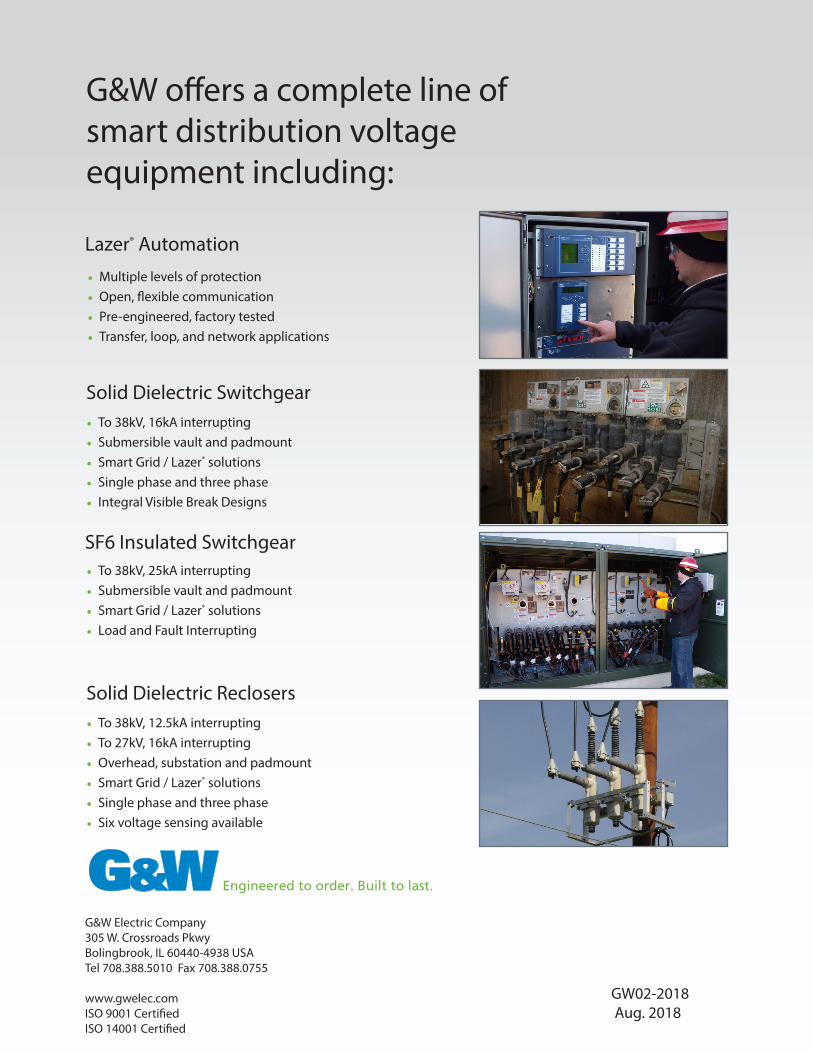
G&W offers a complete line of smart distribution voltage equipment including:
SF6 Insulated Switchgear• To 38kV, 25kA interrupting• Submersible vault and padmount• Smart Grid / Lazer® solutions• Load and Fault Interrupting
Solid Dielectric Switchgear
Solid Dielectric Reclosers• To 38kV, 12.5kA interrupting• To 27kV, 16kA interrupting• Overhead, substation and padmount• Smart Grid / Lazer® solutions• Single phase and three phase• Six voltage sensing available
Lazer® Automation
• Multiple levels of protection• Open, flexible communication• Pre-engineered, factory tested• Transfer, loop, and network applications
G&W Electric Company305 W. Crossroads PkwyBolingbrook, IL 60440-4938 USATel 708.388.5010 Fax 708.388.0755
www.gwelec.comISO 9001 CertifiedISO 14001 Certified
GW02-2018 Aug. 2018
• To 38kV, 16kA interrupting• Submersible vault and padmount• Smart Grid / Lazer® solutions• Single phase and three phase• Integral Visible Break Designs