solenoid valves series - automation-dfw. · pdf filesolenoid valves series solenoid valves 110...
TRANSCRIPT
CAD drawing data catalogis available.
292
VALVES GENERAL CATALOG
INDEX
SOLENOID VALVESSERIES
SOLE
NOID
VAL
VES
110
SERI
ES
Before use, be sure to read the “Safety Precautions” on p. 31.Caution
Features 293Basic Models and Configuration 295110 Series
Specifications 297Cylinder Operating Speed and Flow Rate 299Tandem Solenoid Valve Order Codes 300Solenoid Valve, Air-piloted Valve Order Codes 301Manifold Order Codes 302Operating Principles and Symbols, Major Parts and Materials 303Dimensions of Solenoid Valve 304Dimensions of Manifold 309Made to Order 315
Plug ConnectorDIN ConnectorLED IndicatorBuilt-in Interface UnitAir-piloted Valves 110 Series
Handling Instructions and Precautions 321PC Board Manifold 110 Series
Specifications 323Order Codes 324Dimensions 325Handling Instructions and Precautions 328
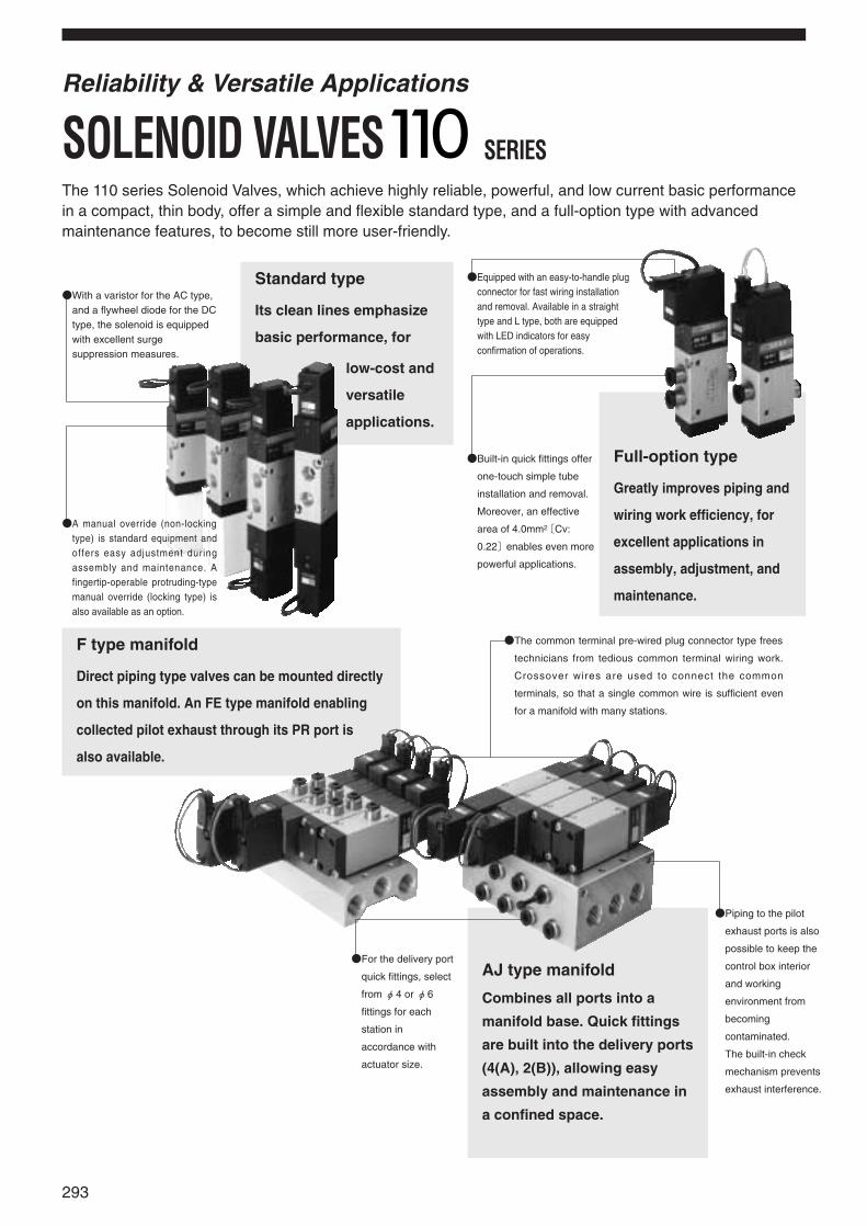
With a varistor for the AC type,and a flywheel diode for the DCtype, the solenoid is equippedwith excellent surgesuppression measures.
Standard type
Its clean lines emphasize
basic performance, for
low-cost and
versatile
applications.
F type manifold
Direct piping type valves can be mounted directly
on this manifold. An FE type manifold enabling
collected pilot exhaust through its PR port is
also available.
Equipped with an easy-to-handle plugconnector for fast wiring installationand removal. Available in a straighttype and L type, both are equippedwith LED indicators for easyconfirmation of operations.
Built-in quick fittings offer
one-touch simple tube
installation and removal.
Moreover, an effective
area of 4.0mm2〔Cv:
0.22〕enables even more
powerful applications.
Full-option type
Greatly improves piping and
wiring work efficiency, for
excellent applications in
assembly, adjustment, and
maintenance.
The common terminal pre-wired plug connector type frees
technicians from tedious common terminal wiring work.
Crossover wires are used to connect the common
terminals, so that a single common wire is sufficient even
for a manifold with many stations.
For the delivery port
quick fittings, select
from φ4 or φ6
fittings for each
station in
accordance with
actuator size.
AJ type manifold
Combines all ports into a
manifold base. Quick fittings
are built into the delivery ports
(4(A), 2(B)), allowing easy
assembly and maintenance in
a confined space.
Piping to the pilot
exhaust ports is also
possible to keep the
control box interior
and working
environment from
becoming
contaminated.
The built-in check
mechanism prevents
exhaust interference.
A manual override (non-lockingtype) is standard equipment andoffers easy adjustment duringassembly and maintenance. Afingertip-operable protruding-typemanual override (locking type) isalso available as an option.
293
The 110 series Solenoid Valves, which achieve highly reliable, powerful, and low current basic performancein a compact, thin body, offer a simple and flexible standard type, and a full-option type with advancedmaintenance features, to become still more user-friendly.
Reliability & Versatile Applications
SOLENOID VALVES SERIES
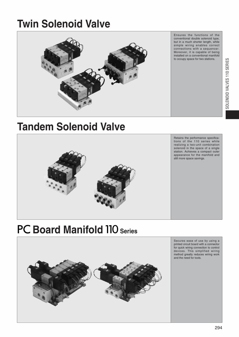
Twin Solenoid ValveEnsures the functions of theconventional double solenoid type,but in a much shorter length, whilesimple wiring enables correctconnections with a sequencer.Moreover, it is capable of beinginstalled on a conventional manifoldto occupy space for two stations.
Tandem Solenoid ValveRetains the performance specifica-tions of the 110 series whilerealizing a two-unit combinationsolenoid in the space of a singlestation. Achieves a compact outerappearance for the manifold andstill more space savings.
Secures ease of use by using aprinted circuit board with a connectorfor quick wiring connection to controldevices. This simplif ied wiringmethod greatly reduces wiring workand the need for tools.
294
SOLE
NOID
VAL
VES
110
SERI
ESBoard Manifold Series
Dire
ctpi
ping
Sub
-bas
epi
ping
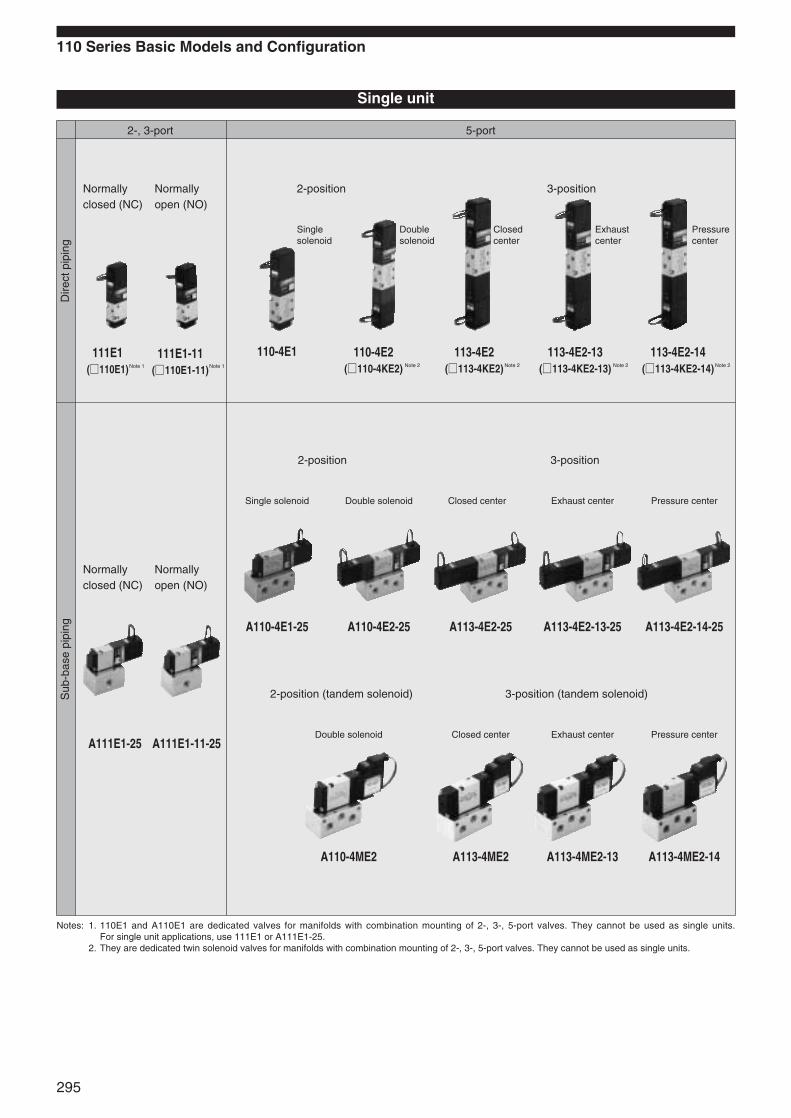
2-, 3-port 5-port
110 Series Basic Models and Configuration
Single unit
Normallyclosed (NC)
Normallyopen (NO)
Normallyclosed (NC)
Normallyopen (NO)
111E1(110E1)
111E1-11(110E1-11)
A111E1-25 A111E1-11-25
2-position 3-position
2-position 3-position
2-position (tandem solenoid) 3-position (tandem solenoid)
110-4E1 110-4E2(110-4KE2)
113-4E2(113-4KE2)
113-4E2-13(113-4KE2-13)
113-4E2-14(113-4KE2-14)
A110-4E1-25 A110-4E2-25 A113-4E2-25 A113-4E2-13-25 A113-4E2-14-25
A110-4ME2 A113-4ME2 A113-4ME2-13 A113-4ME2-14
Singlesolenoid
Doublesolenoid
Closed center
Exhaustcenter
Pressurecenter
Single solenoid Double solenoid Exhaust center Pressure centerClosed center
Double solenoid Closed center Exhaust center Pressure center
Notes: 1. 110E1 and A110E1 are dedicated valves for manifolds with combination mounting of 2-, 3-, 5-port valves. They cannot be used as single units. For single unit applications, use 111E1 or A111E1-25.
2. They are dedicated twin solenoid valves for manifolds with combination mounting of 2-, 3-, 5-port valves. They cannot be used as single units.
295
Note 1 Note 1 Note 2 Note 2 Note 2 Note 2
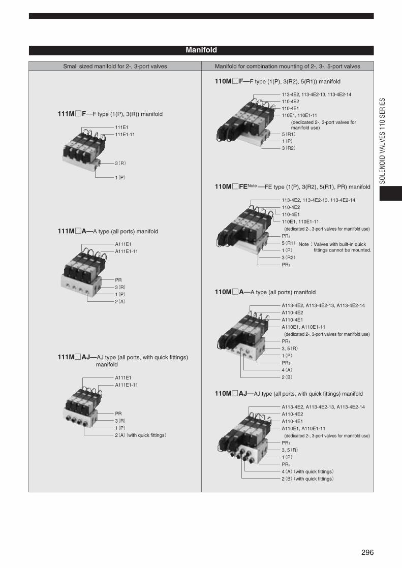
Manifold
Small sized manifold for 2-, 3-port valves Manifold for combination mounting of 2-, 3-, 5-port valves
111MF—F type (1(P), 3(R)) manifold
111E1111E1-11
3(R)
1(P)
111MA—A type (all ports) manifold
A111E1A111E1-11
PR3(R)1(P)2(A)
111MAJ—AJ type (all ports, with quick fittings) manifold
A111E1A111E1-11
PR3(R)1(P)2(A)(with quick fittings)
110MF—F type (1(P), 3(R2), 5(R1)) manifold
113-4E2, 113-4E2-13, 113-4E2-14110-4E2110-4E1110E1, 110E1-11
(dedicated 2-, 3-port valves for manifold use)
5(R1)1(P)3(R2)
110MFENote —FE type (1(P), 3(R2), 5(R1), PR) manifold
113-4E2, 113-4E2-13, 113-4E2-14110-4E2110-4E1110E1, 110E1-11
(dedicated 2-, 3-port valves for manifold use)
PR15(R1)1(P)3(R2)PR2
110MA—A type (all ports) manifold
A113-4E2, A113-4E2-13, A113-4E2-14A110-4E2A110-4E1A110E1, A110E1-11
(dedicated 2-, 3-port valves for manifold use)
PR13, 5(R)1(P)PR24(A)2(B)
110MAJ—AJ type (all ports, with quick fittings) manifold
A113-4E2, A113-4E2-13, A113-4E2-14A110-4E2A110-4E1A110E1, A110E1-11
(dedicated 2-, 3-port valves for manifold use)
PR13, 5(R)1(P)PR24(A)(with quick fittings)2(B)(with quick fittings)
Note:Valves with built-in quickfittings cannot be mounted.
296
SOLE
NOID
VAL
VES
110
SERI
ES

Red Yellow Green RedColor of LED indicator
Grommet type: 300mm [11.8in.] Plug connector type: 300mm [11.8in.]
Plug connector type: 300mm [11.8in.]Note: See made to order on p.315~316.
Wiring typeand leadwire length
Standard
Optional
2 2Allowable leakage current mA 8 4 4
Operating voltage range V 21.6~26.4(24±10%)
10.8~13.2(12±10%)
21.6~26.4(24±10%)
180~264(200 %)
90~132(100 %)
Brown(+)Black(-)
Flywheel diode Varistor Surge absorption transistor
Red(+)Black(-) Yellow White Red (SA), Black (COM)
White (SB)
Over 100
130(1.6W)140 (1.7W) with LED indicator 〔 〕
65(1.6W)75 (1.8W) with LED indicator 〔 〕
50 60 50 60
36 32 18 16
24 20 12 50(1.2W)10
Flywheel diode incorporatedfor surge suppression Shading type Built-in surge
absorption transistor
+32-10
+32-10
Color of lead wire
Surge suppression (as standard)
Starting mA (r.m.s)Current(whenratedvoltage isapplied)
Insulation resistance MΩ
Energizing mA (r.m.s)
Frequency Hz
DC12V DC24V AC100V AC200V DC24V (Tandem solenoid)Item Rated voltage
Internal pilot type
M5×0.8
Not required
0.15~0.7 1.5~7.1 [22~102]
1.05 10.7 [152]
5
5~50 [41~122]
Any
15/25 or below 15/25〔20〕or below 15 or below 15/30 or below
4.2〔0.23〕 4.0〔0.22〕 3.8〔0.21〕 3.6〔0.2〕
50(110-4E2) 50
1373.0 140.0 (Axial direction 294.2 30.0 ) 294.2 30.0
15/15 or below 15/15〔15〕or below 15/20 or below
Media
Operation type
Effective area〔Cv〕Note1 mm2
Air
Port sizeNote 2
Lubrication
Operating pressure range MPa kgf/cm2 [psi.]
Proof pressure MPa kgf/cm2 [psi.]
Maximum operating frequency Hz
Operating temperature range (atmosphere and media) °C [°F]
Mounting direction
Type
ResponsetimeNote 3 msON/OFF
DC12V, DC24V
AC100V, AC200V
Minimum time to energize for self holding ms
Shock resistance m/s2 G
2, 3 ports 5 ports
2 positions 3 positions
Normally closed (NC, standard)or
Normally open (NO, optional)
Single solenoid,Double solenoid
or Tandem solenoid
Twin solenoid
Closed center (standard), Exhaust center (optional),Pressure center (optional)
or Tandem solenoid
Closed center (standard), Exhaust center (optional),Pressure center (optional)
or Twin solenoid
110-4E1110-4E2
A110-4E1A110-4E2
A110-4ME2
110-4KE2Note
A110-4KE2Note
113-4E2
A113-4E2A113-4ME2
113-4KE2
A113-4KE2
111E1(110E1)
110-4E1110-4E2 110-4KE2 113-4E2 113-4KE2
A111E1(A110E1)
A110-4E1A110-4E2 A110-4KE2 A110-4ME2 A113-4E2 A113-4KE2 A113-4ME2
Number of ports
Number of positions
Valve function
Basic model
Item
Direct piping,F, FE typemanifoldsSub-base piping,A, AJ typemanifolds
Remark : For optional specifications and order codes, see p.300~302.Note : The 110E1, A110E1, 110-4KE2, and A110-4KE2 are dedicated valves for manifolds with combination mounting of 2-, 3-, 5-port valves. They cannot be used
as single units. When using 2-,3-port valves as single units, use 111E1 or A111E1-25.
111E1(110E1Note)
A111E1(A110E1Note)
Basic Models and Valve Functions
Basic model
Item
Direct piping,F, FE typemanifoldsSub-base piping,A, AJ typemanifolds
Notes :1. For details, see the effective area on p.298.2. For details, see the port size on p.298.3. Values when air pressure is 0.5MPa 5.1kgf/cm2 [73psi.]. Values in brackets〔 〕for 110-4E2, 110-4KE2, and 110-4ME2 are when switching from the
opposite position, while the values for 113-4E2, 113-4KE2, and A113-4ME2 are those of the closed center valve, when switching from the neutral position.
Specifications
Solenoid Specifications
297
SOLENOID VALVESSERIES

111MAJNote1
110MAJ Manifold
Rc1/8
Quick fitting for φ4 or φ6
Rc1/8 (111MAJ), Rc1/4 (110MAJ)
M5×0.8
1(P)
4(A), 2(B)
3(R), 3, 5(R)
PR
Manifold Rc1/8
Valve M5×0.8110MFE
1(P)
4(A), 2(B)
3(R2), 5(R1)Manifold
Rc1/8
M5×0.8PR
111MA (45×n)+45 [(1.59×n)+1.59]
11 [0.39]
110MFE (40×n)+50 [(1.41×n)+1.76]
110MA (60×n)+60 [(2.12×n)+2.12]
110MAJ -J4 : (67×n)+60 [(2.36×n)+2.12]-J6 : (64×n)+60 [(2.26×n)+2.12]
111MAJ -J4 : (53×n)+45 [(1.87×n)+1.59]-J6 : (50×n)+45 [(1.76×n)+1.59]
10 [0.35]
111MF (15×n)+30 [(0.53×n)+1.06] 5 [0.18]
6 [0.21]110MF (20×n)+30 [(0.71×n)+1.06]
Basic model111E1(110E1)110-4E1110-4E2110-4KE2113-4E2113-4KE2A111E1(A110E1)A110-4E1A110-4E2A110-4KE2A110-4ME2A113-4E2A113-4KE2A113-4ME2
Mass75 [2.65]
80 [2.82]
80 [2.82]
125 [4.41]
175 [6.17]
145 [5.11]
165 [5.82]
80 [2.82] (180 [6.35])
85 [3.00]
85 [3.00] (180 [6.35])
130 [4.59] (225 [7.94])
180 [6.35]
110 [3.88] (205 [7.23])
150 [5.29] (245 [8.64])
170 [6.00]
Location of piping ports
Female thread M5×0.8
-J41 Quick fitting for φ4, for 2(A) (4(A)) port only
-J42 Quick fitting for φ4, for 1(P), 2(A) ports
-J61 Quick fitting for φ6, for 2(A) (4(A)) port only
-J62 Quick fitting for φ6, for1(P), 2(A) ports
Female thread M5×0.8
-J42 Quick fitting for φ4, for 4(A), 2(B) ports only
-J43Note 3 Quick fitting for φ4, for 1(P), 4(A), 2(B) ports
-J62 Quick fitting for φ6, for 4(A), 2(B) ports only
-J43Note 3 Quick fitting for φ6, for 1(P), 4(A), 2(B) ports
Female thread Rc1/8
Female thread M5×0.8
111E1Note1
(110E1Note2)
110-4E1110-4E2110-4KE2113-4E2113-4KE2
A111E1-25Note1
A110-4E1-25A110-4E2-25A113-4E2-25A110-4ME2-25A113-4ME2-25
Standard
Optional
Standard
Optional
1(P)
4(A), 2(B)
3(R2), 5(R1)
PR
Basic model Port specification Port size
111E1Note
(110E1)110-4E1110-4E2110-4KE2
113-4E2113-4KE2
A111E1Note
(A110E1)A110-4E1A110-4E2A110-4KE2A110-4ME2
A113-4E2A113-4KE2A113-4ME2
4.2〔0.23〕
3.8〔0.21〕
4.0〔0.22〕
3.6〔0.20〕
-J4 : 3.6〔0.20〕-J6 : 4.0〔0.22〕
-J4 : 3.4〔0.19〕-J6 : 3.6〔0.20〕
-J4 : 3.6〔0.20〕-J6 : 4.0〔0.22〕
3.6〔0.20〕
When attaching TS4-M5 to the 1(P), 4(A), 2(B) ports, the value is 1.8〔0.10〕.On the F type manifold, attaching TS4-M5 to the 4(A), 2(B) ports gives the
value 2.1〔0.12〕.When large flow rates are required, we recommend the φ6 built-in quick
fitting.
When mounting on a sub-base or manifold.Attaching TS4-01 to the 1(P), 4(A), 2(B) ports on the sub-base gives the value
3.2〔0.18〕.
Basic model Standard (Single valve) Built-in quick fittings Remarks
Notes: 1. The delivery port is the 2(A) for 111E1, A111E1-25.2. Since 110E1 is for manifold use only, piping to the 1 (P) port with a fitting is not possible.3. Not available in 110-4E2, 113-4E2, 110-4KE2, and 113-4KE2.
Note: The delivery port is the 2(A) for 111E1, A111E1.
Notes: 1. The delivery port is the 2(A) for 111MF, 111MA, 111MAJ.2. When the mounting valve is a female thread specification, the ports are this size. For the built-in quick fitting types, quick fittings for φ4 or φ6 are
installed.
Remark: Figures in parentheses( )are the mass with sub-base:-25
Effective Area〔〔Cv〕〕
Solenoid Valve Port Size
Manifold Rc1/8
Valve M5×0.8 Note2
Manifold Rc1/8
111MFNote1
110MF
111MANote1
110MA
1(P)
4(A), 2(B)
3(R), 3(R2), 5(R1)
Manifold
Rc1/8
Rc1/8 (111MA), Rc1/4 (110MA)
M5×0.8
1(P)
4(A), 2(B)
3(R), 3, 5(R)
PR
Manifold model Port Port size
Manifold Connection Port Size
Solenoid Valve Mass
mm2〔Cv〕
g [oz.]
Manifold model Mass calculation of each unit(n=number of units) Block-off plate
Manifold Mass g [oz.]
120 [4.23] (215 [7.58])
298
SOLE
NOID
VAL
VES
110
SERI
ES

Cylinder Operating Speed
Flow Rate
How to obtain cylinder speedTo obtain the time required for the cylinder to complete 1 stroke, addcylinder’s delay time t1 (time between energizing of solenoid valve andactual starting of the cylinder), to the cylinder’s max. speed operatingtime t2.When a cushion is used, add the cushioning time t3, to the abovecalculation. The standard cushioning time t3 is approximately 0.2seconds.
110-4E1113-4E2Measurement conditionsAir pressure : 0.5MPa 5.1kgf/cm2 [73psi.]Piping inner diameter and length : φ2.5 [0.10in.]×
1000mm [39in.]Fitting : Quick fitting TS4-M5
LoadLoad ratio =Cylinder theoretical thrust
(%)
Cylinder stroke : 150mm [5.91in.]
Measurement conditionsAir pressure : 0.5MPa 5.1kgf/cm2 [73psi.]Piping inner diameter and length : φ4 [0.16in.]×
1000mm [39in.]Fitting : Quick fitting TS6-01
LoadLoad ratio =Cylinder theoretical thrust
(%)
Cylinder stroke : 150mm [5.91in.]
Measurement conditionsAir pressure : 0.5MPa 5.1kgf/cm2 [73psi.]Piping inner diameter and length : φ4 [0.16in.]×
1000mm [39in.]Fitting : Quick fitting TS4-01
LoadLoad ratio =Cylinder theoretical thrust
(%)
Cylinder stroke : 150mm [5.91in.]
A110-4E1-25A113-4E2-25
A110-4ME2A113-4ME2
Maximum operating speed
Delay time
How to read the graphWhen the supply pressure is 0.5MPa [73psi.]and the flow rate is 180R/min [6.35ft.3/min.](ANR), the valve outlet pressure becomes0.4MPa [58psi.].
Maximum operating speed
Delay time
Maximum operating speed
Delay time
t1 t2 t3
Cyl
inde
r st
roke
Solen
oid va
lve
ener
gized
Cylin
der s
tart
Cus
hion
ing
impa
ct
Cylin
der s
top
Time
Fitting TS4-M5
0.5MPa
Solenoid valve110-4E1113-4E2
Load
Cyl
inde
r
mm/s
10 20 30 40 50 60
400
800
1200
600
70
200
1000
φ20 [0.787in.]φ25 [0.984in.]φ32 [1.260in.]φ40 [1.575in.]
Load ratio %
Max
imum
ope
ratin
g sp
eed
0
mm/s
10 20 30 40 50 60
400
800
1200
600
70
200
1000
φ50 [1.969in.]
φ20 [0.787in.]φ25 [0.984in.]φ32 [1.260in.]φ40 [1.575in.]
Max
imum
ope
ratin
g sp
eed
Load ratio %0
mm/s
10 20 30 40 50 60
400
800
1200
600
70
200
1000
φ20 [0.787in.]φ25 [0.984in.]φ32 [1.260in.]φ40 [1.575in.]
Load ratio %
Max
imum
ope
ratin
g sp
eed
0
s
10 20 30 40 50 60
0.4
0.8
0.6
70
0.2
1.0
φ32 [1.260in.]φ40 [1.575in.]
φ25 [0.984in.]
0.9
0.7
0.5
0.3
0.1
φ20 [0.787in.]
Load ratio %
Del
ay ti
me
0
s
10 20 30 40 50 60
0.4
0.8
0.6
70
0.2
1.0
φ32 [1.260in.]φ40 [1.575in.]
φ25 [0.984in.]
0.9
0.7
0.5
0.3
0.1
φ50 [1.969in.]
φ20 [0.787in.]
Load ratio %
Del
ay ti
me
0
s
10 20 30 40 50 60
0.4
0.8
0.6
Load ratio %70
0.2
1.0
φ32 [1.260in.]φ40 [1.575in.]
φ25 [0.984in.]
0.9
0.7
0.5
0.3
0.1
φ50 [1.969in.]
φ20 [0.787in.]
Del
ay ti
me
0
0
111E1(110E1)110-4E1110-4E2110-4KE2A111E1(A110E1)A110-4E1A110-4E2A110-4KE2
MPa
0.10.2
0.3
0.4
0.50.6
0.7
0.2
0.1
0.3
0.4
0.5
0.6
0.7
400100 200 300Flow rate R/min(ANR)
Val
ve o
utle
t pre
ssur
e
Supply pressure(MPa)
0.1
0.20.3
0.40.5
0.60.7
0
113-4E2113-4KE2A113-4E2A113-4KE2
MPa
0.2
0.1
0.3
0.4
0.5
0.6
0.7
400100 200 300Flow rate R/min(ANR)
Val
ve o
utle
t pre
ssur
e
Supply pressure(MPa)
A110-4ME2A113-4ME2
MPa
0.1
0.3
0.4
0.5
0.6
0.7
0.2
0.1
0.3
0.4
0.5
0.6
0.7
0400100 200 300
0.2
Flow rate R/min(ANR)
Val
ve o
utle
t pre
ssur
e
Supply pressure(MPa)
Fitting TS6-01
0.5MPa
Solenoid valveA110-4E1-25A113-4E2-25
Load
Cyl
inde
r
Fitting TS4-01
Load
0.5MPa
Cyl
inde
r
299
1mm/s = 0.0394in./sec. 1mm/s = 0.0394in./sec.1mm/s = 0.0394in./sec.
1MPA = 145psi.
1R/min = 0.0353ft.3/min.
Sub-basepiping
5-portdoublesolenoid
5-port3-position
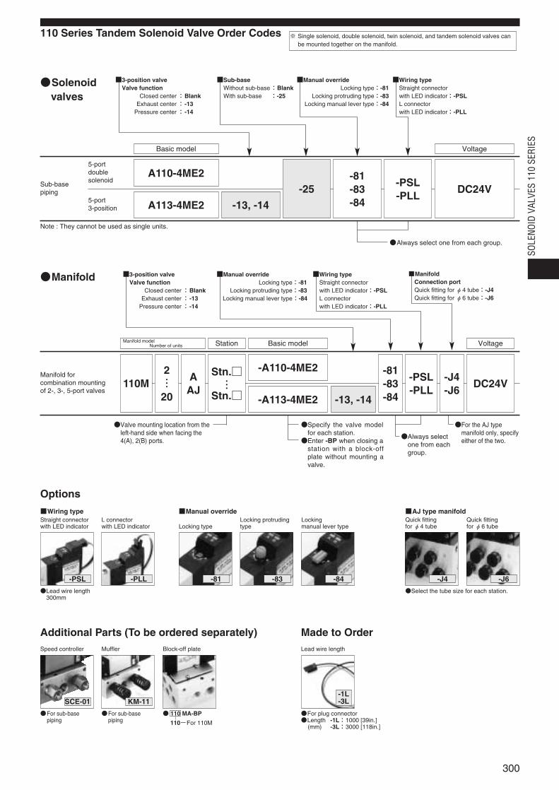
110 Series Tandem Solenoid Valve Order Codes
Options
Solenoidvalves
A110-4ME2
Basic model Voltage
A113-4ME2 -13, -14
-25-81-83-84
-PSL-PLL
DC24V
3-position valve Valve function
Closed center:BlankExhaust center: -13
Pressure center: -14
Sub-baseWithout sub-base:BlankWith sub-base :-25
Manual overrideLocking type:-81
Locking protruding type:-83Locking manual lever type:-84
Wiring typeStraight connector with LED indicator:-PSLL connectorwith LED indicator:-PLL
Always select one from each group.
Note : They cannot be used as single units.
Manifold forcombination mountingof 2-, 3-, 5-port valves
Manifold
Manifold modelNumber of units Station Basic model Voltage
110M2…20
AAJ
Stn.…
Stn.
-81-83-84
-PSL-PLL
-J4-J6
DC24V
ManifoldConnection portQuick fitting for φ4 tube:-J4Quick fitting for φ6 tube:-J6
Always selectone from eachgroup.
Valve mounting location from theleft-hand side when facing the4(A), 2(B) ports.
Specify the valve modelfor each station.Enter -BP when closing a
station with a block-offplate without mounting avalve.
For the AJ typemanifold only, specifyeither of the two.
-A110-4ME2
-A113-4ME2 -13, -14
Wiring type Manual overrideStraight connectorwith LED indicator
Lead wire length300mm
For sub-basepiping
For sub-basepiping
110 MA-BP
110-For 110M
Select the tube size for each station.
L connector with LED indicator
-PSL -PLL
Additional Parts (To be ordered separately)Speed controller Muffler
SCE-01
For plug connectorLength -1L:1000 [39in.]
(mm) -3L:3000 [118in.]
Made to OrderLead wire length
-1L-3LKM-11
Block-off plate
Locking type
-81
AJ type manifoldQuick fitting for φ4 tube
-J4
Quick fitting for φ6 tube
-J6
Locking protrudingtype
-83
Locking manual lever type
-84
3-position valve Valve function
Closed center:BlankExhaust center: -13
Pressure center: -14
Manual overrideLocking type:-81
Locking protruding type:-83Locking manual lever type:-84
Wiring typeStraight connector with LED indicator:-PSLL connector with LED indicator:-PLL
※ Single solenoid, double solenoid, twin solenoid, and tandem solenoid valves canbe mounted together on the manifold.
300
SOLE
NOID
VAL
VES
110
SERI
ES
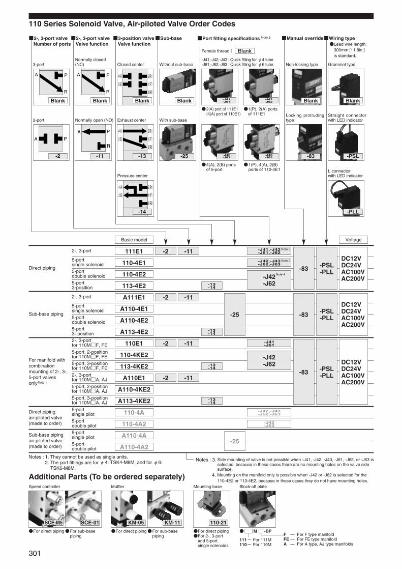
110 Series Solenoid Valve, Air-piloted Valve Order Codes
2-, 3-port valve Number of ports
2-, 3-port valve Valve function
3-position valve Valve function
Sub-base Port fitting specifications Note 2 Manual overrideWiring typeLead wire length:
300mm [11.8in.] is standard.
Direct piping
Sub-base piping
For manifold withcombinationmounting of 2-, 3-,5-port valvesonlyNote 1
Direct pipingair-piloted valve (made to order)
Sub-base pipingair-piloted valve(made to order)
2-, 3-port
5-portsingle solenoid5-portdouble solenoid5-port3-position
2-, 3-port
5-portsingle solenoid5-portdouble solenoid5-port3- position2-, 3-port for 110MF, FE5-port, 2-position for 110MF, FE5-port, 3-position for 110MF, FE2-, 3-port for 110MA, AJ5-port, 2-position for 110MA, AJ5-port, 3-position for 110MA, AJ5-portsingle pilot5-portdouble pilot5-portsingle pilot5-portdouble pilot
-83 -PSL-PLL
-83 -PSL-PLL
-83 -PSL-PLL
DC12VDC24VAC100VAC200V
DC12VDC24VAC100VAC200V
DC12VDC24VAC100VAC200V
Notes : 3. Side mounting of valve is not possible when -J41, -J42, -J43, -J61, -J62, or -J63 isselected, because in these cases there are no mounting holes on the valve sidesurface.
4. Mounting on the manifold only is possible when -J42 or -J62 is selected for the110-4E2 or 113-4E2, because in these cases they do not have mounting holes.
111E1
110-4E1
110-4E2
113-4E2
A111E1
A110-4E1
A110-4E2
A113-4E2
110E1
110-4KE2
113-4KE2
A110E1
A110-4KE2
A113-4KE2
110-4A
110-4A2
A110-4A
A110-4A2
Basic model
-13-14
-13-14
-13-14
-13-14
-11-2
-11
-25
-25
-2
-11-2
-11-2
-J42-J62
-J41,-J42-J61,-J62
-J42,-J43-J62,-J63
-J42-J62
-J41-J61
-J42,-J43-J62,-J63
-J42-J62
For direct piping For direct piping For direct pipingFor 2-, 3-port
and 5-portsingle solenoids
Additional Parts (To be ordered separately)Speed controller Muffler
SCE-M5
For sub-base piping
SCE-01
For sub-base piping
KM-11 110-21
Mounting base
M -BP
111- For 111M 110- For 110M
Block-off plate
A P
R
A P
3-port
2-port
A P
R
A P
R
Normally closed(NC)
Normally open (NO)
4(A)
2(B)
5(R1)
3(R2)
1(P)
4(A)
2(B)
5(R1)
3(R2)
1(P)
Closed center
Exhaust center
4(A)
2(B)
5(R1)
3(R2)
1(P)
Pressure center
Without sub-base
With sub-base
-J41,-J42,-J43 : Quick fitting for φ4 tube-J61,-J62,-J63 : Quick fitting for φ6 tube Non-locking type
Locking protrudingtype
Grommet type
Straight connectorwith LED indicator
L connector with LED indicator
-2 -11 -13 -25
-J41-J61
-J42-J62
-J42-J62
-J43-J63 -83 -PSL
-14 -PLL
2(A) port of 111E1 (4(A) port of 110E1)
1(P), 2(A) portsof 111E1
4(A), 2(B) portsof 5-port
1(P), 4(A), 2(B)ports of 110-4E1
Voltage
Notes : 1. They cannot be used as single units.2. The port fittings are for φ4: TSK4-M8M, and for φ6:
TSK6-M8M.
F — For F type manifold FE — For FE type manifold A — For A type, AJ type manifolds
KM-05
Blank Blank Blank Blank Blank Blank
Female thread: Blank
301
Note 3
Note 3
Note 4
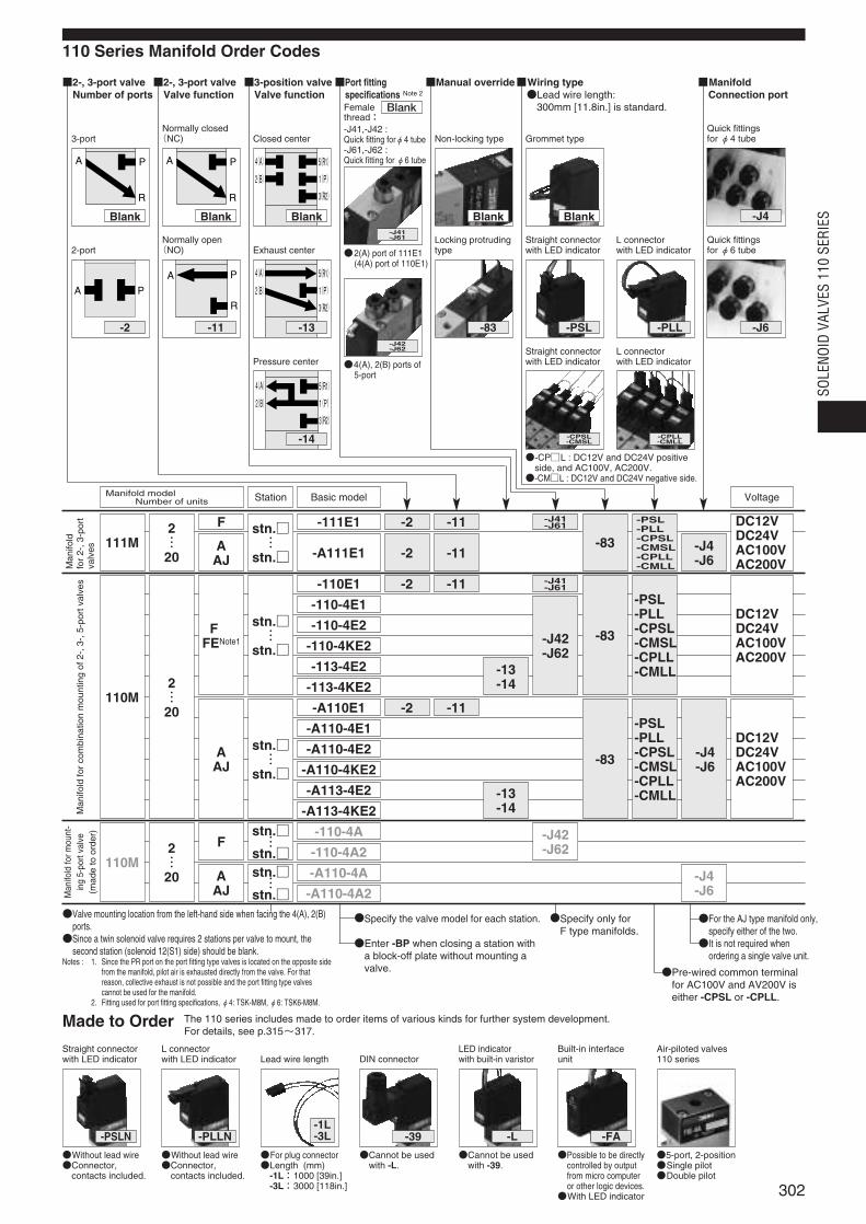
110 Series Manifold Order Codes
2-, 3-port valveNumber of ports
2-, 3-port valveValve function
3-position valveValve function
Port fitting specifications Note 2
Manual overrideWiring typeLead wire length:
300mm [11.8in.] is standard.
ManifoldConnection port
Man
ifold
for
2-,3
-por
tva
lves
Man
ifold
form
ount
-in
g5-
port
valv
e(m
ade
toor
der)
Man
ifold
for
com
bina
tion
mou
ntin
gof
2-,3
-,5-
port
valv
es
-83 -J4-J6
-PSL-PLL-CPSL-CMSL-CPLL-CMLL
DC12VDC24VAC100VAC200V
-83-J42-J62
-13-14
-PSL-PLL-CPSL-CMSL-CPLL-CMLL
DC12VDC24VAC100VAC200V
Specify the valve model for each station.
Enter -BP when closing a station witha block-off plate without mounting avalve.
-111E1stn.…
stn.
2…20
111M
stn.…
stn.
2…20
110M
F
AAJ
F注1FENote1
stn.…
stn.2…20
110M
F
stn.…
stn.AAJ
stn.…
stn.
AAJ
Basic modelStationManifold modelNumber of units
-11-2
-110E1
-110-4E1
-110-4E2
-110-4KE2
-113-4E2
-113-4KE2
-A110E1
-A110-4E1
-A110-4E2
-A110-4KE2
-A113-4E2
-A113-4KE2
-110-4A
-110-4A2
-A110-4A
-A110-4A2
-11-2
-83
-13-14
-J42-J62
-J4-J6
-PSL-PLL-CPSL-CMSL-CPLL-CMLL
-J4-J6
DC12VDC24VAC100VAC200V
-11-2
-A111E1 -11-2
-J41-J61
-J41-J61
Without lead wireConnector,
contacts included.
Made to Order
Straight connectorwith LED indicator
Without lead wireConnector,
contacts included.
L connector with LED indicator
For plug connectorLength (mm)
-1L:1000 [39in.]-3L:3000 [118in.]
Lead wire length
-PSLN
A P
R
A P
3-port
2-port
A P
R
A P
R
Normally closed(NC)
Normally open(NO)
4(A)
2(B)
5(R1)
3(R2)
1(P)
4(A)
2(B)
5(R1)
3(R2)
1(P)
Closed center
Exhaust centerLocking protrudingtype
4(A)
2(B)
5(R1)
3(R2)
1(P)
Pressure center
-J41,-J42 :Quick fitting forφ4 tube-J61,-J62 :Quick fitting for φ6 tube
Grommet typeNon-locking typeQuick fittings for φ4 tube
Quick fittings for φ6 tube
L connector with LED indicator
Straight connectorwith LED indicator
L connector with LED indicator
Straight connectorwith LED indicator
-2 -11 -13
2(A) port of 111E1 (4(A) port of 110E1)
4(A), 2(B) ports of 5-port
-CPL : DC12V and DC24V positiveside, and AC100V, AC200V.-CML : DC12V and DC24V negative side.
Voltage
Valve mounting location from the left-hand side when facing the 4(A), 2(B)ports.Since a twin solenoid valve requires 2 stations per valve to mount, the
second station (solenoid 12(S1) side) should be blank.Notes : 1. Since the PR port on the port fitting type valves is located on the opposite side
from the manifold, pilot air is exhausted directly from the valve. For thatreason, collective exhaust is not possible and the port fitting type valvescannot be used for the manifold.
2. Fitting used for port fitting specifications, φ4: TSK-M8M, φ6: TSK6-M8M.
-PLLN
Cannot be usedwith -L.
Cannot be usedwith -39.
DIN connector
-39
LED indicator with built-in varistor
-L
Possible to be directlycontrolled by outputfrom micro computeror other logic devices.With LED indicator
Built-in interfaceunit
-FA
5-port, 2-positionSingle pilotDouble pilot
Air-piloted valves110 series
-1L-3L
Specify only for F type manifolds.
For the AJ type manifold only,specify either of the two.It is not required when
ordering a single valve unit.
The 110 series includes made to order items of various kinds for further system development.For details, see p.315~317.
Pre-wired common terminalfor AC100V and AV200V iseither -CPSL or -CPLL.
Blank Blank Blank
-83
-J41-J61
-J42-J62
-CPSL-CMSL
-CPLL-CMLL
-PLL-PSL -J6
-J4
-14
Blank Blank
Femalethread:
Blank
302
SOLE
NOID
VAL
VES
110
SERI
ES
Manifold
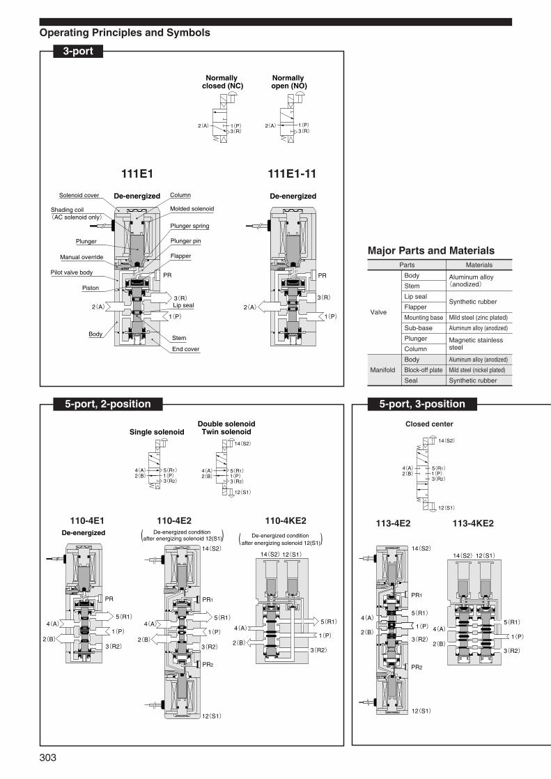
Synthetic rubber
Synthetic rubber
Magnetic stainlesssteel
Aluminum alloy (anodized)
Aluminum alloy (anodized)
Lip seal
Sub-base
Plunger
Column
Body
Block-off plate
Seal
Flapper
Body Aluminum alloy(anodized)
Mild steel (zinc plated)
Mild steel (nickel plated)
Stem
Mounting base
Parts Materials
Operating Principles and Symbols
2(A) 1(P)3(R) 3(R)
2(A) 1(P)
Normally closed (NC)
Normally open (NO)
3-port
Major Parts and Materials
111E1-11111E1
5-port, 2-position 5-port, 3-position
Valve
Closed center
110-4E1 110-4E2 110-4KE2 113-4E2 113-4KE2
2(A)
PR
3(R)
1(P)
De-energized
PR
4(A)
2(B)
5(R1)
1(P)
3(R2)
De-energized
PR1
PR2
4(A)
2(B)
5(R1)
1(P)
3(R2)
14(S2)
12(S1)
De-energized condition after energizing solenoid 12(S1)( )
12(S1)14(S2)
4(A)
2(B)
5(R1)
1(P)
3(R2)
De-energized condition after energizing solenoid 12(S1)( )
PR1
PR2
4(A)
2(B)
5(R1)
1(P)
3(R2)
14(S2)
12(S1)
4(A)
2(B)
5(R1)
1(P)
3(R2)
14(S2)12(S1)
4(A)2(B)
5(R1)1(P)3(R2)
14(S2)
12(S1)
4(A)2(B)
5(R1)1(P)3(R2)
4(A)2(B)
5(R1)1(P)3(R2)
14(S2)
12(S1)
Single solenoidDouble solenoidTwin solenoid
De-energizedSolenoid cover
Shading coil(AC solenoid only)
Plunger
Manual override
Pilot valve body
Piston
Body
2(A)
Column
Molded solenoid
Plunger spring
Plunger pin
Flapper
PR
3(R)Lip seal
1(P)
Stem
End cover
303
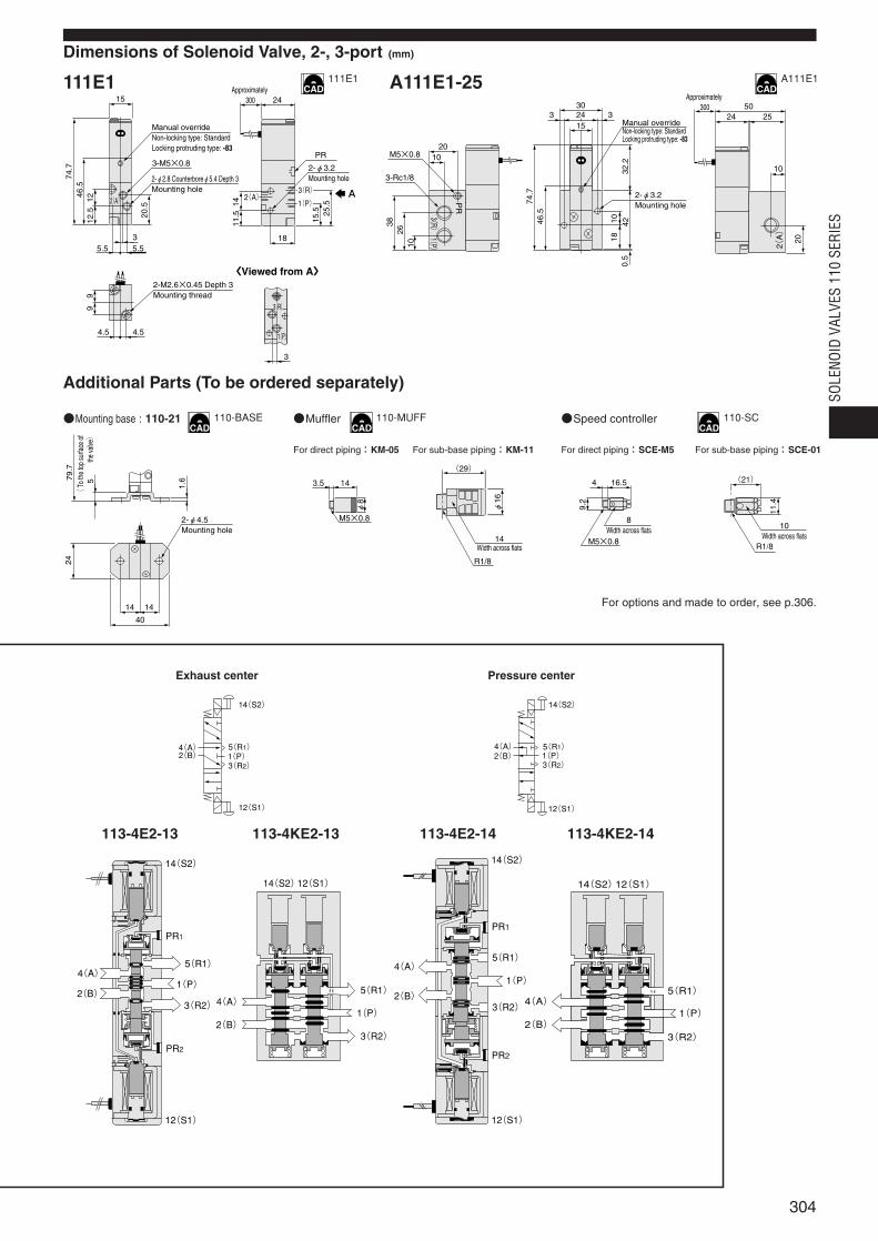
Dimensions of Solenoid Valve, 2-, 3-port (mm)
111E1 A111E1-25
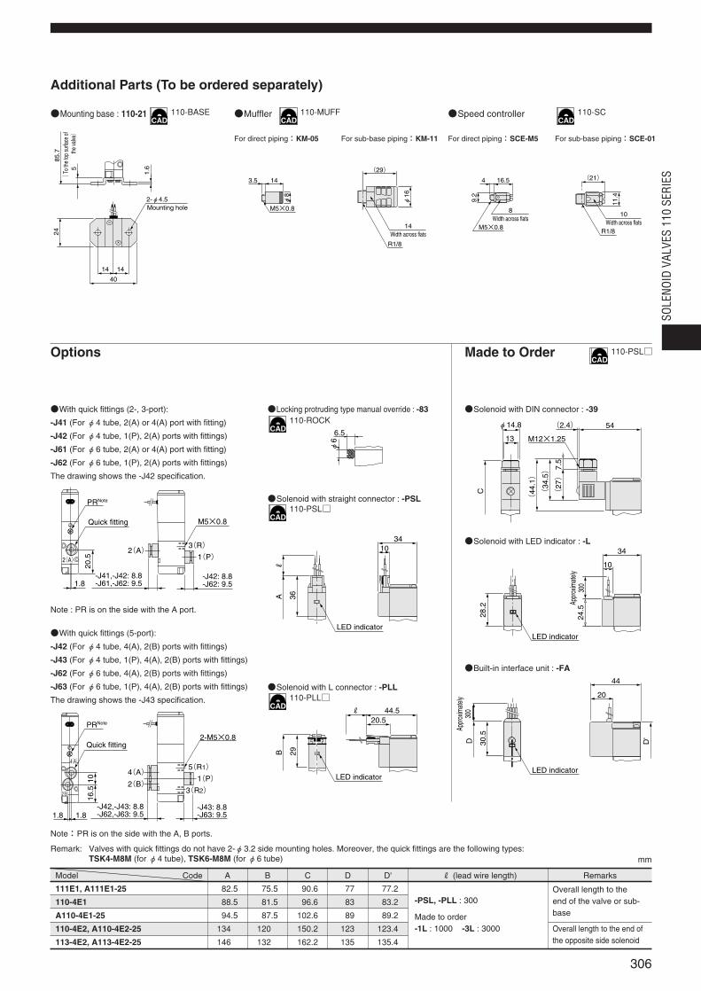
Additional Parts (To be ordered separately)
Mounting base : 110-21 Muffler
For direct piping:KM-05 For sub-base piping:KM-11 For direct piping:SCE-M5 For sub-base piping:SCE-01
Speed controller
For options and made to order, see p.306.
Exhaust center Pressure center
113-4E2-13 113-4KE2-13 113-4E2-14 113-4KE2-14
PR1
PR2
4(A)
2(B)
5(R1)
1(P)
3(R2)
14(S2)
12(S1)
4(A)
2(B)
5(R1)
1(P)
3(R2)
14(S2)12(S1)
4(A)2(B)
5(R1)1(P)3(R2)
14(S2)
12(S1)
PR1
PR2
4(A)
2(B)
5(R1)
1(P)
3(R2)
14(S2)
12(S1)
4(A)
2(B)
5(R1)
1(P)
3(R2)
14(S2)12(S1)
4(A)2(B)
5(R1)1(P)3(R2)
14(S2)
12(S1)
20
3826
10
10M5×0.8
3-Rc1/8
1
(P
)3
(R
)
PR
30
74.7
46.5
180.
510
32.2
42
2415
33Manual overrideNon-locking type: StandardLocking protruding type: -83
2-φ3.2Mounting hole
Approximately 300 50
24 25
10
20
2
(A
)
2-φ4.5Mounting hole
79.7
( T
o th
e to
p su
rface
of
the
valve)
5
24
1.6
14 14
40
143.5
M5×0.8
φ8
(29)
14Width across flats
φ16
R1/8
M5×0.8
16.54
9.2
8Width across flats
(21)
10Width across flatsR1/8
11.4
2-M2.6×0.45 Depth 3Mounting thread
4.54.5
99
5.5
74.7
46.5
12.5 20
.5 14
15.5 25
.5
11.5
12
5.53
2-φ2.8 Counterboreφ5.4 Depth 3Mounting hole
3-M5×0.8
Manual overrideNon-locking type: StandardLocking protruding type: -83
15Approximately
300 24
PR
2-φ3.2Mounting hole
18
2(A)2(A) 1(P)
1(P)
3(R)
3
3(R)
A
〈Viewed from A〉
111E1 A111E1
110-BASE 110-MUFF 110-SC
304
SOLE
NOID
VAL
VES
110
SERI
ES
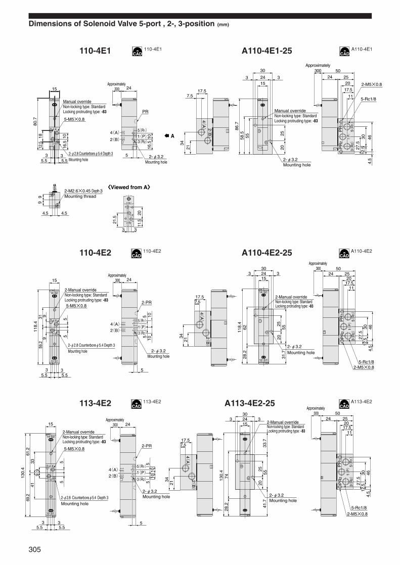
Dimensions of Solenoid Valve 5-port , 2-, 3-position (mm)
110-4E1 A110-4E1-25
110-4E2 A110-4E2-25
113-4E2 A113-4E2-25
99
15
5-M5×0.8
3 35.55.5
2-φ2.8 Counterboreφ5.4 Depth 3Mounting hole
2-M2.6×0.45 Depth 3Mounting thread
1016
.5
2-φ3.2Mounting hole
24
5
Manual overrideNon-locking type: StandardLocking protruding type: -83
80.7
12.5
18
Approximately 300
PR
4.5 4.5
21.5
2011
.5
3 3
〈Viewed from A〉
16.5
10 A4(A)
2(B)
5(R1)
1(P)
3(R2)
5(R1)1(P)3(R2)
4(A)
2(B)
2-M5×0.8
2-φ3.2Mounting hole
Manual overrideNon-locking type: StandardLocking protruding type: -83
5-Rc1/8
17.57.5
3421
4(A)
2(B)
86.7
58.5
55
30
3 32415
2025
5024 25
20
17.5
11
30 464.
5
27.5
12.5
PR
1P
R2
1(P) 5(
R1)
3(R
2)
Approximately300
15
5-M5×0.8
3 35.55.5
2-φ2.8 Counterboreφ5.4 Depth 3Mounting hole
1010
2-φ3.2Mounting hole
24
5
4(A)
2(B)
2-Manual overrideNon-locking type: StandardLocking protruding type: -83
118.4
59.2
31
Approximately 300
2-PR
5
55
5
99
12(S1)
14(S2)
4(A)2(B)
5(R1)1(P)3(R2)
2-M5×0.8
2-φ3.2Mounting hole
2-Manual overrideNon-locking type: StandardLocking protruding type: -83
5-Rc1/8
17.57.5
3421
4(A)
2(B)
118.
462
28.2
303 324
1520
5525
5024 25
2017.5
11
30 464.
5
27.5
PR
1P
R2
1(P) 5(
R1)
3(R
2)
31.7
12.5
12(S1)
14(S2)
Approximately 300
15
5-M5×0.8
3 35.55.5
2-φ2.8 Counterboreφ5.4 Depth 3Mounting hole
1010
2-φ3.2Mounting hole
24
5
4(A)
2(B)
2-Manual overrideNon-locking type: StandardLocking protruding type: -83
130.
469
.261
.2
2-PR
5
55
5
99 1(P)
4133
5(R1)
3(R2)
12(S1)
14(S2)
4(A)2(B)
Approximately 300
2-M5×0.8
2-φ3.2Mounting hole
2-Manual overrideNon-locking type: StandardLocking protruding type: -83
5-Rc1/8
17.57.5
3421
4(A)
2(B)
130.
474
28.2
303 324
15
2055
25
5024 25
2017.5
11
30 464.
5
27.5
PR
1P
R2
1(P) 5(
R1)
3(R
2)
41.7
33.7
12.5
Approximately 300
110-4E1 A110-4E1
110-4E2 A110-4E2
113-4E2 A113-4E2
305
Model Code A B C D D' R (lead wire length) Remarks
Additional Parts (To be ordered separately)
Mounting base : 110-21 Muffler
For direct piping:KM-05 For sub-base piping:KM-11 For direct piping:SCE-M5 For sub-base piping:SCE-01
Speed controller
Options Made to Order
With quick fittings (2-, 3-port):
-J41 (For φ4 tube, 2(A) or 4(A) port with fitting)
-J42 (For φ4 tube, 1(P), 2(A) ports with fittings)
-J61 (For φ6 tube, 2(A) or 4(A) port with fitting)
-J62 (For φ6 tube, 1(P), 2(A) ports with fittings)
The drawing shows the -J42 specification.
Note : PR is on the side with the A port.
With quick fittings (5-port):
-J42 (For φ4 tube, 4(A), 2(B) ports with fittings)
-J43 (For φ4 tube, 1(P), 4(A), 2(B) ports with fittings)
-J62 (For φ6 tube, 4(A), 2(B) ports with fittings)
-J63 (For φ6 tube, 1(P), 4(A), 2(B) ports with fittings)
The drawing shows the -J43 specification.
Note:PR is on the side with the A, B ports.
Locking protruding type manual override : -83
Solenoid with straight connector : -PSL
Solenoid with L connector : -PLL
Solenoid with DIN connector : -39
Solenoid with LED indicator : -L
Built-in interface unit : -FA
Remark: Valves with quick fittings do not have 2-φ3.2 side mounting holes. Moreover, the quick fittings are the following types:TSK4-M8M (for φ4 tube), TSK6-M8M (for φ6 tube)
111E1, A111E1-25 82.5 75.5 90.6 77 77.2
110-4E1 88.5 81.5 96.6 83 83.2
A110-4E1-25 94.5 87.5 102.6 89 89.2
110-4E2, A110-4E2-25 134 120 150.2 123 123.4
113-4E2, A113-4E2-25 146 132 162.2 135 135.4
-PSL, -PLL : 300
Made to order-1L : 1000 -3L : 3000
Overall length to theend of the valve or sub-base
Overall length to the end of the opposite side solenoid
mm
2-φ4.5
85.7
5
24
1.6
14 14
40
( T
o th
e to
p su
rface
of
the
valve)
Mounting hole
143.5
M5×0.8
φ8
(29)
φ16
R1/8
14Width across flats
M5×0.8
16.54
9.2
8Width across flats
(21)
R1/8
11.4
10Width across flats
20.5
2(A)3(R)
1(P)
M5×0.8
1.8
2(A)
PR
Quick fitting
-J41,-J42: 8.8-J61,-J62: 9.5
-J42: 8.8-J62: 9.5
Note
16.5
10
1.81.8
2(B)
4(A)
2-M5×0.8
4(A)
2(B)
5(R1)
1(P)
3(R2)
-J42,-J43: 8.8-J62,-J63: 9.5
-J43: 8.8-J63: 9.5
PR
Quick fitting
Note
6.5
φ6
RA 36
3410
LED indicator
C
(44
.1)
(34
.5)
(27)7
.5
φ14.8
13 M12×1.25
(2.4) 54
28.2
24.5
10
34
LED indicator
Appr
oxim
ately
300
44
20
D 30.5
D'
LED indicator
Appr
oxim
ately
300
29B
44.5R
20.5
LED indicator
110-BASE 110-MUFF 110-SC
110-ROCK
110-PSL
110-PSL
110-PLL
306
SOLE
NOID
VAL
VES
110
SERI
ES
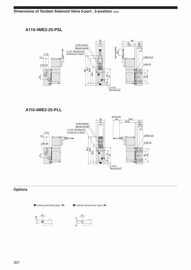
Dimensions of Tandem Solenoid Valve 5-port , 2-position (mm)
A110-4ME2-25-PSL
A110-4ME2-25-PLL
Options
Locking protruding type: -83 Locking manual lever type: -84
A
A
DC24V
B
B
1(P)
4(A)
2(B)
5(R
1)
3(R
2)
PR
1P
R2
2-M5×0.8
3-Rc1/8
684237.5
2520
17.511
30 46552520
302415
98.7 92
.784
.556
.5
17.5
7.5
2-Rc1/8
13
(Mounting hole)2-φ3.2
2-LED indicator
Manual override
2-φ2.8(Mounting hole)Counterboreφ5.4 Depth 3
App
roxi
mat
ely
300
A
A
DC24V
A C B
B
B
PR
1P
R2
78.852.8 25
2017.5
11
2-M5×0.8
3-Rc1/830 46
302415
2520
55
90.5
84.5
56.5
2-Rc1/8
7.5
17.5
13 1(P)
4(A)
2(B)
5(R
1)
3(R
2)
(Mounting hole)2-φ3.2
Approximately 300
2-LED indicatorManual override
2-φ2.8(Mounting hole)Counterboreφ5.4 Depth 3
6
φ6
4
63
307
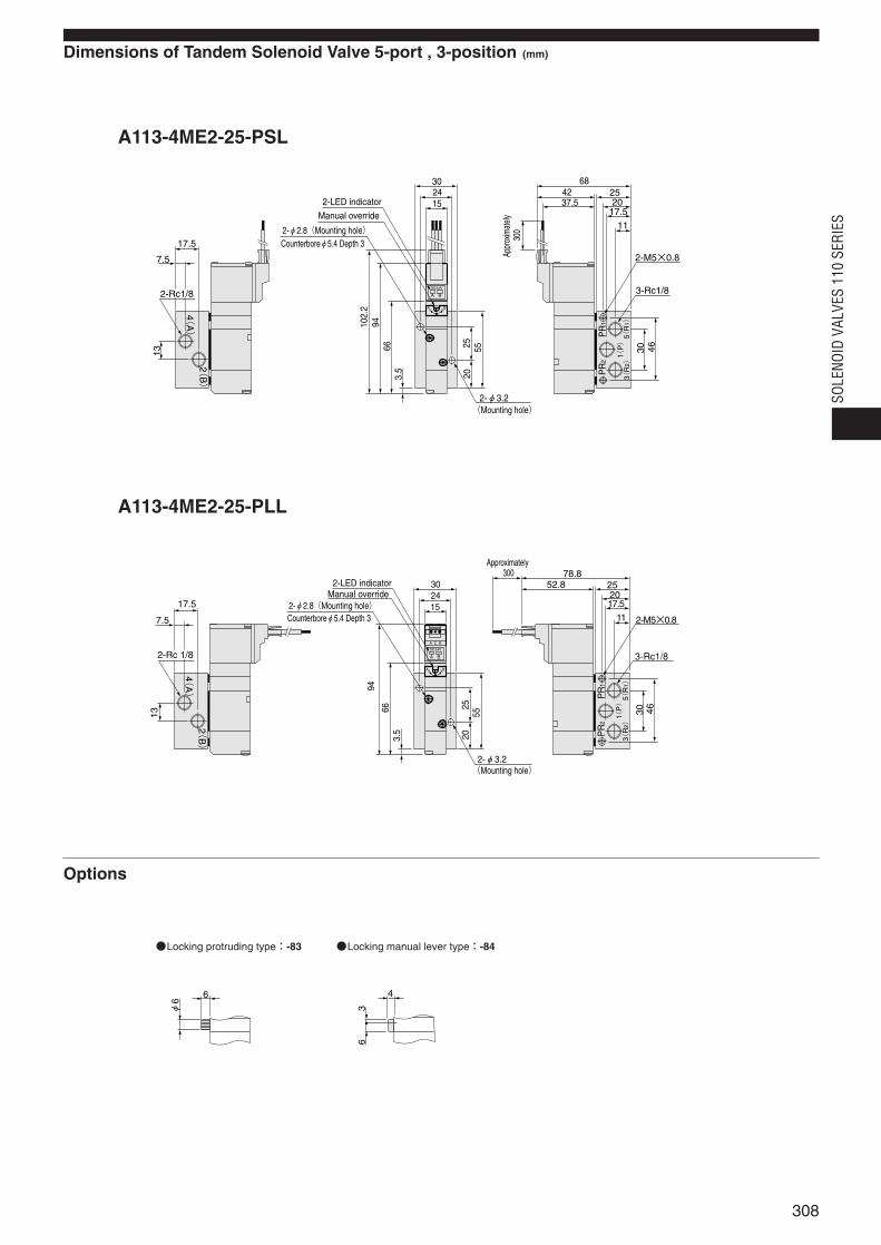
Dimensions of Tandem Solenoid Valve 5-port , 3-position (mm)
A113-4ME2-25-PSL
A113-4ME2-25-PLL
Options
Locking protruding type:-83 Locking manual lever type:-84
A
A
DC24V
B
B
PR
1P
R2
17.5
7.5
2-Rc1/8
13
302415
2-φ3.2
9466
3.5
2025 55
102.
2
2-M5×0.8
3-Rc1/8
30 46
11
17.52025
684237.5
1(P)
4(A)
2(B)
5(R
1)
3(R
2)
(Mounting hole)
2-LED indicator
Manual override
2-φ2.8(Mounting hole)
Appr
oxim
ately
30
0
Counterboreφ5.4 Depth 3
A
A
DC24V
A C B
B
B
PR
1P
R2
17.5
7.5
2-Rc 1/8
13
302415
94
663.
5
5525
20
78.852.8 25
2017.5
11 2-M5×0.8
30 463-Rc1/8
1(P)
4(A)
2(B)
5(R
1)
3(R
2)
(Mounting hole)2-φ3.2
2-LED indicatorManual override
2-φ2.8(Mounting hole)Counterboreφ5.4 Depth 3
Approximately 300
6
φ6
4
63
308
SOLE
NOID
VAL
VES
110
SERI
ES
111M2F 48 41
4F 80 73
6F 112 105
8F 144 137
10F 176 169
12F 208 201
14F 240 233
16F 272 265
18F 304 297
20F 336 329
3F 64 57
5F 96 89
7F 128 121
9F 160 153
11F 192 185
13F 224 217
15F 256 249
17F 288 281
19F 320 313
Model L P
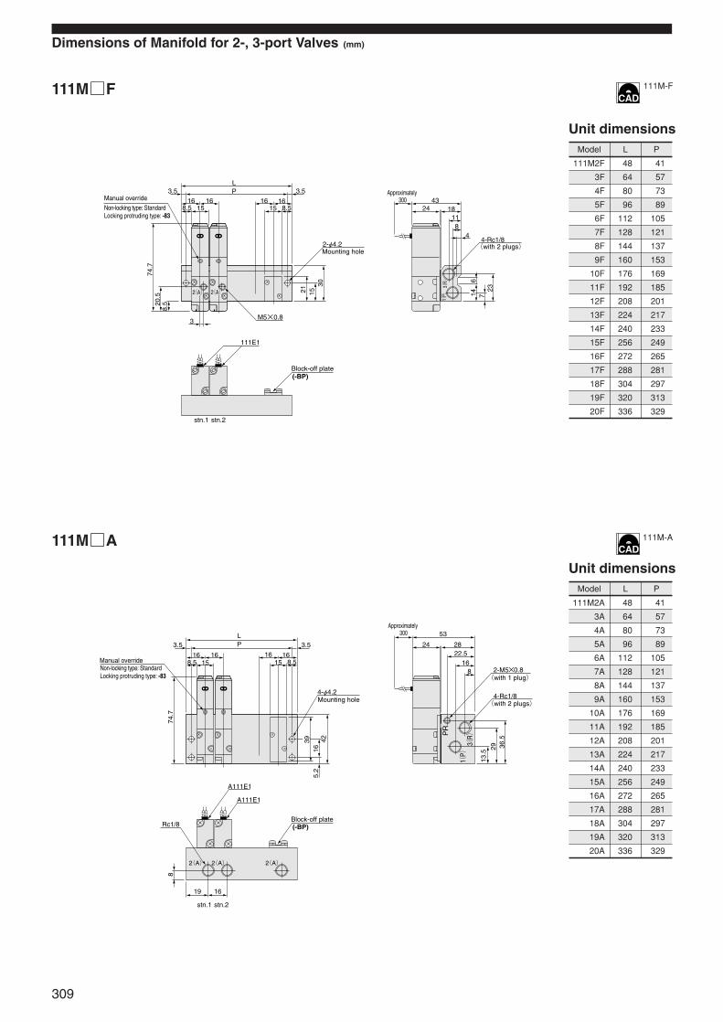
Dimensions of Manifold for 2-, 3-port Valves (mm)
Unit dimensions
111MF
111MA
111M2A 48 41
4A 80 73
6A 112 105
8A 144 137
10A 176 169
12A 208 201
14A 240 233
16A 272 265
18A 304 297
20A 336 329
3A 64 57
5A 96 89
7A 128 121
9A 160 153
11A 192 185
13A 224 217
15A 256 249
17A 288 281
19A 320 313
Model L P
Unit dimensions
1(P) 3(
R)
2(A) 2(A)
LP 3.53.5
16 16 16 168.5 8.515 15
21
8.520
.574
.7
1530
614 7
23
M5×0.83
2-φ4.2
111E1
Block-off plate(-BP)
stn.1 stn.2
4324 18
118
44-Rc1/8(with 2 plugs)
Mounting hole
Non-locking type: StandardLocking protruding type: -83
Manual overrideApproximately
300
1(P)
PR
3(R)
2(A)2(A) 2(A)
LP 3.53.5
16 16 16 168.5 8.515 15Manual override
Non-locking type: StandardLocking protruding type: -83
39
74.7
8
165.
242
29
13.5
36.5
4-φ4.2
A111E1
A111E1
Block-off plate(-BP)
stn.1 stn.2
53
24 2822.5
168 2-M5×0.8
4-Rc1/8
(with 1 plug)
(with 2 plugs)Mounting hole
1619
Rc1/8
Approximately 300
111M-F
111M-A
309

111E1, A111E1
110-4E1, 110-4KE2, 113-4KE2, A110-4E1
110-4E2, A110-4E2
113-4E2, A113-4E2
A B C D D' R(lead wire length)
82.5 75.5 90.6 77 77.2
-PSL, -PLL : 300Made to order -1L : 1000, -3L : 3000
88.5 81.5 96.6 83 83.2
134 120 150.2 123 133.4
146 132 162.2 135 135.4
111MAJ
111M2AJ 48 41
4AJ 80 73
6AJ 112 105
8AJ 144 137
10AJ 176 169
12AJ 208 201
14AJ 240 233
16AJ 272 265
18AJ 304 297
20AJ 336 329
3AJ 64 57
5AJ 96 89
7AJ 128 121
9AJ 160 153
11AJ 192 185
13AJ 224 217
15AJ 256 249
17AJ 288 281
19AJ 320 313
Model L P
Unit dimensions
Options Made to Order
Model Code
mm
Remark: Valves with quick fittings do not have 2-φ3.2 side mounting holes. Moreover, the quick fittings arethe following types:TSK4-M8M (for φ4 tube), TSK6-M8M (for φ6 tube)
With quick fitting (2-, 3-port):
-J41 (For φ4 tube, 2(A) or 4(A) port with fitting)
-J61 (For φ6 tube, 2(A) or 4(A) port with fitting)
Note : PR is on the A port side.
With quick fittings (5-port):
-J42 (For φ4 tube, 4(A), 2(B) ports with fittings)
-J62 (For φ6 tube, 4(A), 2(B) ports with fittings)
Note:PR is on the side with the 4(A), 2(B) ports.
Locking protruding type manual override: -83 Solenoid with DIN connector: -39
Solenoid with LED indicator: -L
Built-in interface unit: -FA
Solenoid with straight connector: -PSL
Solenoid with L connector: -PLL
1(P)
PR
3(R)
2(A)2(A) 2(A)
-J6:
7.5
-J4:
6.8
LP 3.53.5
16 16 16 168.5 8.515 15Manual override
Non-locking type: StandardLocking protruding type: -83
39
8
165.
242
2913
.5
36.5
4-φ4.2
A111E1
A111E1
Block-off plate(-BP)
stn.1 stn.2
53
24 2822.5
168
2-M5×0.8
4-Rc1/8
(with 1 plug)
(with 2 plugs)Mounting hole
1619
Quick fitting
74.7
Approximately 300
1(P)
20.5
1.8 43
2(A) 3(R)
2(A)
-J61: 9.5-J41: 8.8
PR
Quick fitting
Note
55
1.8
3(R2)
5(R1)
1(P)
431.8
4(A)
2(B)
4(A)
2(B)
-J62: 9.5-J42: 8.8
PR
Quick fitting
Note
6.5
φ6
RA 36
3410
LED indicator
C
(44
.1)
(34
.5)
(27)7
.5
φ14.8
13 M12×1.25
(2.4) 5428
.2
24.5
LED indicator
10
34
Appr
oxim
ately
300
44
20
D 30.5
D'
LED indicator
y30
0
29B
44.5R
20.5
LED indicator
110-ROCK
110-PSL
110-PSL
110-PLL
310
SOLE
NOID
VAL
VES
110
SERI
ES
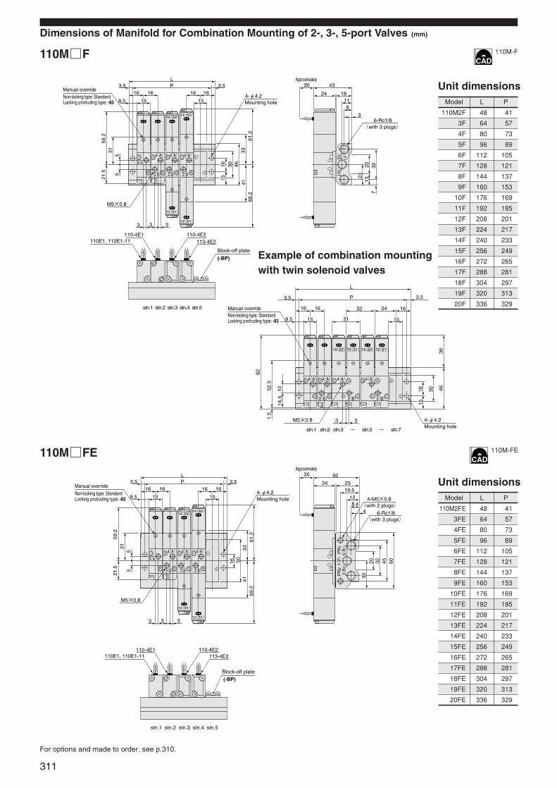
110M2F 48 41
4F 80 73
6F 112 105
8F 144 137
10F 176 169
12F 208 201
14F 240 233
16F 272 265
18F 304 297
20F 336 329
3F 64 57
5F 96 89
7F 128 121
9F 160 153
11F 192 185
13F 224 217
15F 256 249
17F 288 281
19F 320 313
Model L P
Dimensions of Manifold for Combination Mounting of 2-, 3-, 5-port Valves (mm)
Unit dimensions
110MF
110MFE
Example of combination mountingwith twin solenoid valves
For options and made to order, see p.310.
110M2FE 48 41
4FE 80 73
6FE 112 105
8FE 144 137
10FE 176 169
12FE 208 201
14FE 240 233
16FE 272 265
18FE 304 297
20FE 336 329
3FE 64 57
5FE 96 89
7FE 128 121
9FE 160 153
11FE 192 185
13FE 224 217
15FE 256 249
17FE 288 281
19FE 320 313
Model L P
Unit dimensions
1(P)
5(R1)
3(R2)
14(S2)
12(S1)
12(S1)
14(S2)
14(S2)12(S1)14(S2)12(S1)
2(B)
2(B) 2(B) 2(B)
2(B) 2(B)
4(A)4(A)4(A) 4(A)
4(A) 4(A) 4(A)
4(A)
Approximately 300
Manual overrideNon-locking type: StandardLocking protruding type: -83
LP3.5
8.5
69.2
61.2
4133
21.5
59.2
315
5
3.516 16 16 16
1515
33 3
M5×0.8
4-φ4.2Mounting hole
110-4E1110E1, 110E1-11 113-4E2
110-4E2
Block-off plate
(-BP)
stn.1 stn.2 stn.3 stn.4 stn.5
stn.1 stn.2 stn.3 - stn.5 - stn.7
43
24 18118
36-Rc1/8
⦆(with 3 plugs)
2313
207
32
Manual overrideNon-locking type: StandardLocking protruding type: -83
L
P3.5 3.5
8.5
463016
36
52.5
1.5
82
16.5
10
1616 16 32
3 3
24
1515
M5×0.8 4-φ4.2Mounting hole
31
15
1615
4630
PR
1P
R2
14(S2)14(S2)
12(S1)
12(S1)
Approximately 300
⦆(with 3 plugs)
⦆(with 2 plugs)
(-BP)Block-off plate
Manual overrideNon-locking type: StandardLocking protruding type: -83
LP3.5
8.5
69.2
4133
61.2
21.5
59.2
315
5
3.516 16 16 16
1515
33 3
M5×0.8
4-φ4.2Mounting hole
110-4E1110E1, 110E1-11 113-4E2
110-4E2
stn.1 stn.2 stn.3 stn.4 stn.5
50
24 2519.5
128.4
4
4-M5×0.8
6-Rc1/8
3220 45 60
30
16 50 1(P) 5(
R1)
3(R2)
2(B)
4(A)
2(B)
4(A)
2(B)
4(A)
4(A)
110M-F
110M-FE
311

For options and made to order, see p.310.
110MA
110MAJ
110M2A 48 41
4A 80 73
6A 112 105
8A 144 137
10A 176 169
12A 208 201
14A 240 233
16A 272 265
18A 304 297
20A 336 329
3A 64 57
5A 96 89
7A 128 121
9A 160 153
11A 192 185
13A 224 217
15A 256 249
17A 288 281
19A 320 313
Model L P
Unit dimensions
110M2AJ 48 41
4AJ 80 73
6AJ 112 105
8AJ 144 137
10AJ 176 169
12AJ 208 201
14AJ 240 233
16AJ 272 265
18AJ 304 297
20AJ 336 329
3AJ 64 57
5AJ 96 89
7AJ 128 121
9AJ 160 153
11AJ 192 185
13AJ 224 217
15AJ 256 249
17AJ 288 281
19AJ 320 313
Model L P
Unit dimensions
14(S2)14(S2)
12(S1)
12(S1)
PR
2
1(P)
PR
1
3・5(
R)
Manual overrideNon-locking type: StandardLocking protruding type: -83
LP3.5
8.5
69.2
32.5
4133
61.2
21.5
59.2
31
3.5
16 16 16 16
15152-φ4.2Mounting
hole
A110-4E1
A110E1, A110E1-11 A113-4E2
A110-4E2
stn.1 stn.2 stn.3 stn.4 stn.5
24 35
60
1513
29.5 4-M5×0.8
2-Rc1/4
2-Rc1/8
38427.
5
24.5
50 53
2-Rc1/8
357.5
19.5
2(B)2(B) 2(B)
4(A) 4(A)4(A)
Approximately300
⦆(with 2 plugs)
⦆(with 1 plug)
⦆(with 1 plug)
(-BP)Block-off plate
Plug B when mounting A110E1Plug A when mounting A110E1-11
14(S2)
12(S1)
12(S1)
14(S2)
-J6:
21.
1-J
4: 1
6.7
Approximately300
⦆(with 2 plugs)
⦆(with 1 plug)
⦆(with 1 plug)
Manual overrideNon-locking type: StandardLocking protruding type: -83
LP3.5
8.5
69.2
3361
.2
59.2
21.5
31
3.516 16 16 16
15152-φ4.2
A110-4E1
A110E1, A110E1-11 A113-4E2
A110-4E2
stn.1 stn.2 stn.3 stn.4 stn.5
60
24 3529.5
1513
4-M5×0.8
2-Rc1/4
2-Rc1/8
38427.
5
24.5
5032
.5
4153
5 36.5
20.5
PR
2P
R1
1(P)
2(B)2(B) 2(B)
4(A) 4(A)4(A)
3・5(
R)
-J6:
7.5
-J4:
6.8
Mounting hole
(-BP)
PlugFor 2-, 3-port valve mounting
2-Quick fittings (per each station)Block-off plate
Plug B when mounting A110E1Plug A when mounting A110E1-11
110M-A
110M-A
312
SOLE
NOID
VAL
VES
110
SERI
ES
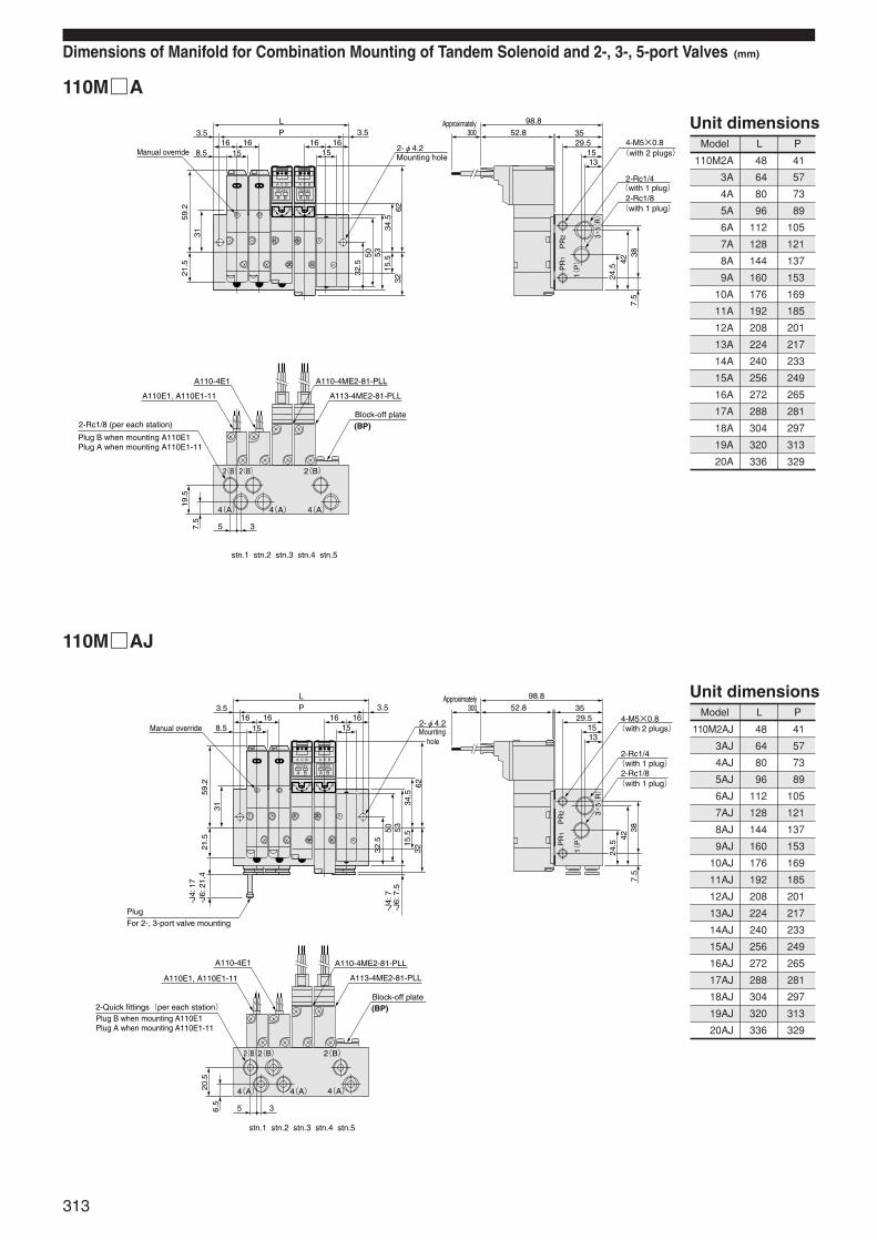
Dimensions of Manifold for Combination Mounting of Tandem Solenoid and 2-, 3-, 5-port Valves (mm)
110MA
110MAJ
Model L P
110M2A 48 41
3A 64 57
4A 80 73
5A 96 89
6A 112 105
7A 128 121
8A 144 137
9A 160 153
10A 176 169
11A 192 185
12A 208 201
13A 224 217
14A 240 233
15A 256 249
16A 272 265
17A 288 281
18A 304 297
19A 320 313
20A 336 329
Unit dimensions
Model L P
110M2AJ 48 41
3AJ 64 57
4AJ 80 73
5AJ 96 89
6AJ 112 105
7AJ 128 121
8AJ 144 137
9AJ 160 153
10AJ 176 169
11AJ 192 185
12AJ 208 201
13AJ 224 217
14AJ 240 233
15AJ 256 249
16AJ 272 265
17AJ 288 281
18AJ 304 297
19AJ 320 313
20AJ 336 329
Unit dimensions
A
A
DC24V
A C B
B
B
A
A
DC24V
A C B
B
B
Manual override
LP3.5
8.5
3234
.562
59.2
21.5
31
3.516 16 16 16
15152-φ4.2
A110-4E1
A110E1, A110E1-11
A110-4ME2-81-PLL
A113-4ME2-81-PLL
stn.1 stn.2 stn.3 stn.4 stn.5
98.8
52.8 3529.5
1513
4-M5×0.8
2-Rc1/4
2-Rc1/8
3842
7.5
24.5
5032
.5 15.5
53
5 37.5
19.5
PR
1
1(P)
PR
2
2(B)2(B) 2(B)
4(A) 4(A)4(A)
3・5(
R)
Mounting hole ⦆(with 2 plugs)
Approximately300
⦆(with 1 plug)
⦆(with 1 plug)
2-Rc1/8 (per each station)
Plug B when mounting A110E1Plug A when mounting A110E1-11
(BP)Block-off plate
A
A
DC24V
A C B
B
B
A
A
DC24V
A C B
B
B
LP3.5
8.5
3234
.562
59.2
21.5
31
3.516 16 16 16
15152-φ4.2
A110-4E1
A110E1, A110E1-11
A110-4ME2-81-PLL
A113-4ME2-81-PLL
stn.1 stn.2 stn.3 stn.4 stn.5
98.8
52.8 3529.5
1513
4-M5×0.8
2-Rc1/4
2-Rc1/8
3842
7.5
24.5
5032
.5 15.5
53
5 36.5
20.5
PR
1P
R2
1(P)
2(B)2(B) 2(B)
4(A) 4(A)4(A)
3・5(
R)
PlugFor 2-, 3-port valve mounting
-J6:
21.
4-J
4: 1
7
Manual override
-J6:
7.5
-J4:
7
Mounting hole
Approximately300
⦆(with 2 plugs)
⦆(with 1 plug)
⦆(with 1 plug)
(BP)2-Quick fittings(per each station)Block-off plate
Plug B when mounting A110E1Plug A when mounting A110E1-11
313
314
SOLE
NOID
VAL
VES
110
SERI
ES
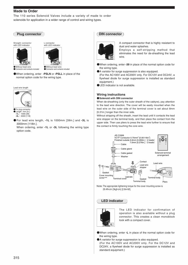
Made to OrderThe 110 series Solenoid Valves include a variety of made to ordersolenoids for application in a wider range of control and wiring types.
Straight connectorwith LED indicator
Without lead wireConnector and contacts included
When ordering, enter -PSLN or -PSLL in place of thenormal option code for the wiring type.
-PSLN
Lead wire length
For plug connectorLength mm [in.]
-1L:1000 [39]-3L:3000 [118]
For lead wire length, -1L is 1000mm [39in.] and -3L is3000mm [118in.].When ordering, enter -1L or -3L following the wiring typeoption code.
-1L-3L
L connector with LED indicator
Without lead wireConnector and contacts included
-PLLN
-39
A compact connector that is highly resistant todust and water splashes.Employs a self-stripping method thateliminates the need for de-sheathing the leadwire.
LED indicator
-L
The LED indicator for confirmation ofoperation is also available without a plugconnector. This creates a clean monoblocklook with a compact cover.
When ordering, enter -39 in place of the normal option code forthe wiring type.A varistor for surge suppression is also equipped.
(For the AC100V and AC200V only. For DC12V and DC24V, aflywheel diode for surge suppression is installed as standardequipment.)
LED indicator is not available.
When ordering, enter -L in place of the normal option code forthe wiring type.A varistor for surge suppression is also equipped.
(For the AC100V and AC200V only. For the DC12V andDC24V, a flywheel diode for surge suppression is installed asstandard equipment.)
Wiring instructionsSolenoid with DIN connectorWhen de-sheathing (only the outer sheath of the cabtyre), pay attentionto the lead wire direction. The cover will be easily mounted when thelead wire on the outer side of the terminal cover is set about 8mm[0.31in.] longer than the inner side.Without stripping off the sheath, insert the lead until it contacts the leadwire stopper on the terminal body, and then place the contact from theupper side. Then use pliers to press the lead wire further to ensure thatthe contact is firmly touching the core wire.
2
1
3+_Cable
Cable gland
Cable gasket
Washer
Gasket
Gasket
Cover mounting screw Terminal cover
Lead wire
Terminal body Pliers
Solenoid terminal arrangement
JIS C3306VCTF Conductor 0.75mm2 [0.00116in.2] Finished outside 6.6mm [0.260in.](2 leads) 7.0mm [0.276in.](3 leads)
Contact
Lead wire stopper
Note Terminal body
Lead wire
Note: The appropriate tightening torque for the cover mounting screw is29.4N•cm 3kgf•cm [2.6in• lbf].
315
Plug connector DIN connector

Built-in interface unit
Vp〔V〕 R1
12 390Ω1/4W
24 1.0KΩ1W
Wiring type and lead wire length Grommet type: 300mm [11.8in.]
50 60 50 60
36 32 18 16
24 20 12 10
50 60 50 60
0.3 0.4 0.6 0.8
Current
Leakagecurrent
Frequency Hz
Starting mA(r.m.s.)
Energizing mA(r.m.s.)
Frequency Hz
Current mA(r.m.s.)
180~250(200 %)+25
-10
90~125(100 %)Operating voltage range AC V
Rated voltage AC V 100
Shading type
200
Type
Solenoidside
Item
Input side
Rated voltage DC V 5
Voltage range DC V 4~6
Current (when 5V DC is applied) mA 18
Operating voltage DC V 4 or below
Return voltage DC V 0.8 or over
Color of lead wire Red (+), Black (-)
Color of lead wire Yellow White
Color of LED indicator (as standard)
Voltage resistance Min. AC1500V at input side and solenoid side
Zero-cross function Available
Insulation resistance MΩ Over 100
Yellow Green
Surge suppression (as standard) Built-in varistor on solenoid side
Specifications
-FA
Includes an interface unit with a photo transistor.Can be directly controlled by a microcomputerand logic chip, and is equipped with full electricnoise countermeasures and LED indicators.
When ordering, enter -FA in place of the normal option codefor the wiring type.Cannot be ordered in combination with any other solenoid
option.Rated voltages for the solenoid are AC100V and AC200V only.
Block diagram
Example of control circuits
Wiring instructions
1. Control by transistor
2. Control by TTL, IC
3. Control by relay contact
4. When input is not a DC5V power supplyInstall resistance externally to drop the input voltage to 4~6V.
The interface unit is a triac with a photo coupler. Applying DC5V to theinput terminals when AC power is applied on the solenoid side causesthe LED inside the unit to light up, turns on the triac, and energizes thesolenoid. At this time, an LED indicator turns on.When the input side voltage reaches 0V, the LED inside the unit shutsoff, the triac is turned off, and the solenoid is de-energized. At this time,the LED indicator is turned off.With a built-in zero-cross circuit, the zero-cross voltage is used to turnthe power on, and the zero-cross current to turn it off.
1. Separate the input side and solenoid side lead wires by color. Neverapply AC power/6VDC or more to the input side.
2. Ensure that voltage ripple on the input side remains within the rangeshown below.
3. Even when a wrong polarity is applied to the input side, a built-indiode for protection against reverse polarity eliminates any worryabout short circuiting. The valve will not operate, however.
4. A varistor and condensor are built-in in the solenoid power supplyside, for protection circuit against external surge voltages. As aresult, there is a 0.3mA leakage current in AC100V, and a 0.6mAleakage current in AC200V.
5. The operation and return times of the interface unit are 10ms or lesswith a 50Hz AC power supply, and 8ms or less with a 60Hz ACpower supply.
Solenoid Specifications for Valve with Built-in Interface Unit
+25-10
In the case of VCE= 0〔V〕
Example
R1=Vp-5-VCE
〔Ω〕18×10-3
VnVm
0V
Vm<6.0V(Vm:Peak voltage)Vn>4.0V(Vn:Lowest voltage)
LED<Input side> <Solenoid side>
Lead wire: Red +
Lead wire: Black -
Interface unit
Zerocrosscircuit
Condenservaristor
Lead wire color:AC100V: YellowAC200V: White
Solenoid
Vcc
Vcc
Vcc
TTL
Vp
VcE R1
Vcc
Red
Red
Black
Black
Red
Black
Red
Black
Black
AC power supply
AC power supply
AC power supply
AC power supply
AC power supply
NPN type
PNP type
Interface solenoid valve
Interface solenoid valve
Interface solenoid valve
Interface solenoid valve
Interface solenoid valve
AC100V: YellowAC200V: White
AC100V: YellowAC200V: White
Example : 7406 (able to control up to 2 interface 74LS244 solenoid valves.)
Contact
AC100V: YellowAC200V: White
AC100V: YellowAC200V: White
AC100V: YellowAC200V: White
Color of lead wireSolenoid power supply AC100V: YellowSolenoid power supply AC200V: White
Color of lead wireInput ― DC0V: Black
Color of lead wireInput + DC5V: Red
316
SOLE
NOID
VAL
VES
110
SERI
ES
( )when ratedvoltage isapplied
Between input side andsolenoid side, and betweenwhole terminals and body
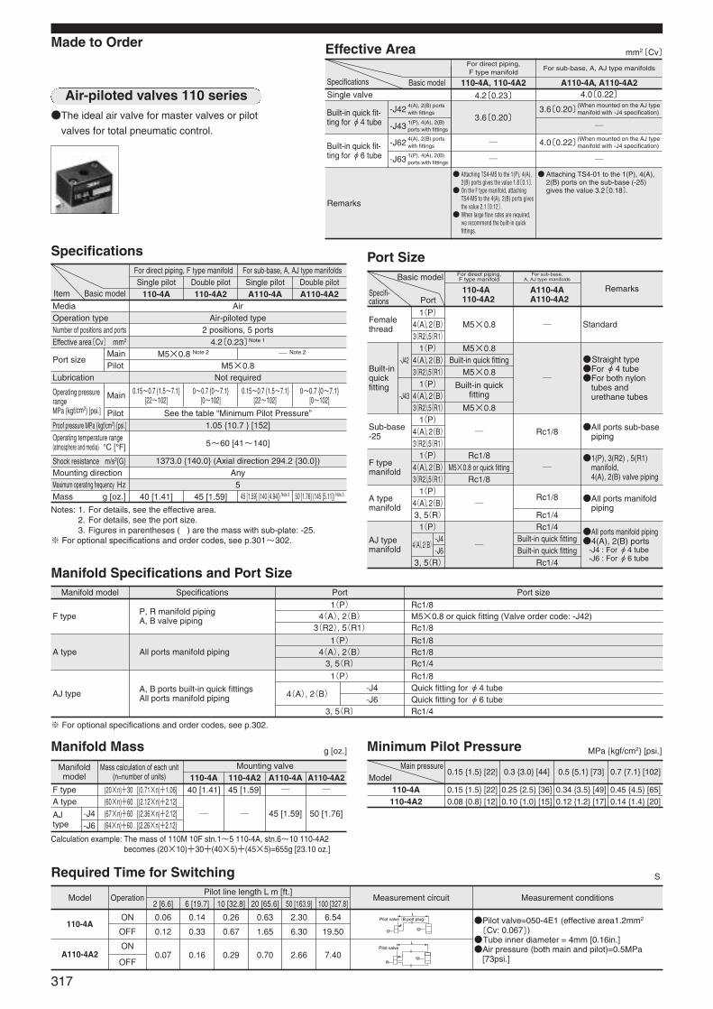
A type1(P) Rc1/8
4(A), 2(B) Rc1/83, 5(R) Rc1/4
All ports manifold piping
1(P) Rc1/8
4(A), 2(B)-J4 Quick fitting for φ4 tube-J6 Quick fitting for φ6 tube
3, 5(R) Rc1/4
Rc1/4Built-in quick fittingBuilt-in quick fitting
Rc1/4
All ports manifold piping4(A), 2(B) ports
-J4 : For φ4 tube-J6 : For φ6 tube
AJ typemanifold
Manifold model
Manifoldmodel
Model OperationPilot line length L m [ft.]
Measurement circuit Measurement conditions2 [6.6] 6 [19.7] 10 [32.8] 20 [65.6] 50 [163.9] 100 [327.8]
Mass calculation of each unit(n=number of units)
Mounting valve
40 [1.41] 45 [1.59]F type (20×n)+30 [(0.71×n)+1.06]
45 [1.59] 50 [1.76]A type (60×n)+60 [(2.12×n)+2.12]
AJtype
-J4-J6
(67×n)+60 [(2.36×n)+2.12](64×n)+60 [(2.26×n)+2.12]
110-4A A110-4A2110-4A2 A110-4A
110-4A
A110-4A2
Specifications Port Port size
1(P)
4(A),2(B)-J4-J6
3, 5(R)
Rc1/8M5×0.8 or quick fitting
Rc1/8
1(P), 3(R2) , 5(R1)manifold, 4(A), 2(B) valve piping
F typemanifold
1(P)4(A),2(B)3(R2),5(R1)
M5×0.8Built-in quick fittingM5×0.8
Built-in quickfitting
M5×0.8
Straight typeFor φ4 tubeFor both nylon
tubes andurethane tubes
Built-inquickfitting
1(P)4(A),2(B)3(R2),5(R1)1(P)4(A),2(B)3(R2),5(R1)
-J42
-J43
M5×0.8
1(P) Rc1/84(A), 2(B) M5×0.8 or quick fitting (Valve order code: -J42)3(R2), 5(R1) Rc1/8
Rc1/8
Rc1/8
Rc1/4
Standard
All ports sub-basepiping
All ports manifoldpiping
Femalethread
Sub-base-25
A typemanifold
Basic model
Port
For direct piping, F type manifold
For sub-base, A, AJ type manifolds
110-4A110-4A2
A110-4AA110-4A2
Remarks
3.6〔0.20〕3.6〔0.20〕
Remarks
Attaching TS4-M5 to the 1(P), 4(A),2(B) ports gives the value 1.8〔0.1〕.
On the F type manifold, attachingTS4-M5 to the 4(A), 2(B) ports givesthe value 2.1〔0.12〕.
When large flow rates are required,we recommend the built-in quickfittings.
Attaching TS4-01 to the 1(P), 4(A),2(B) ports on the sub-base (-25)gives the value 3.2〔0.18〕.
Built-in quick fit-ting for φ4 tube
-J42
-J43
Lubrication
Media AirOperation type Air-piloted typeNumber of positions and ports 2 positions, 5 portsEffective area〔Cv〕 mm2 4.2〔0.23〕Note 1
Port sizeMainPilot
M5×0.8 Note 2 Note 2
M5×0.8Not required
See the table “Minimum Pilot Pressure”Proof pressure MPa kgf/cm2 [psi.] 1.05 10.7 [152]Operating temperature range (atmosphere and media) °C [°F]
0.15~0.7 1.5~7.1 [22~102]
0~0.7 0~7.1[0~102]
0.15~0.7 1.5~7.1[22~102]
0~0.7 0~7.1[0~102]
5~60 [41~140]
Shock resistance m/s2G 1373.0 140.0 (Axial direction 294.2 30.0)Mounting direction AnyMaximum operating frequency Hz 5Mass g [oz.]
F type P, R manifold pipingA, B valve piping
AJ type A, B ports built-in quick fittingsAll ports manifold piping
Item Basic model
For direct piping, F type manifoldSingle pilot Double pilot Single pilot Double pilot
110-4A 110-4A2 A110-4A A110-4A2
For sub-base, A, AJ type manifolds
Made to Order
The ideal air valve for master valves or pilot
valves for total pneumatic control.
Effective Area mm2〔Cv〕
Specifications
Manifold Specifications and Port Size
Required Time for Switching
40 [1.41] 45 [1.59] 45 [1.59] (140 [4.94]) Note 3 50 [1.76] (145 [5.11]) Note 3
Operating pressure rangeMPa kgf/cm2 [psi.]
Main
Pilot
Notes: 1. For details, see the effective area. 2. For details, see the port size. 3. Figures in parentheses ( ) are the mass with sub-plate: -25.
※ For optional specifications and order codes, see p.301~302.
※ For optional specifications and order codes, see p.302.
Calculation example: The mass of 110M 10F stn.1~5 110-4A, stn.6~10 110-4A2becomes (20×10)+30+(40×5)+(45×5)=655g [23.10 oz.]
Single valve 4.2〔0.23〕 4.0〔0.22〕4(A), 2(B) portswith fittings
(When mounted on the AJ typemanifold with -J4 specification)
1(P), 4(A), 2(B)ports with fittings
-J62 4(A), 2(B) portswith fittings
-J63
1(P)4(A),2(B)3(R2),5(R1)
1(P)4(A),2(B)3(R2),5(R1)
1(P)4(A),2(B)3, 5(R)
1(P), 4(A), 2(B)ports with fittings
Built-in quick fit-ting for φ6 tube
4.0〔0.22〕
Specifications Basic model
For direct piping, F type manifold
For sub-base, A, AJ type manifolds
110-4A, 110-4A2 A110-4A, A110-4A2
Port Size
Manifold Mass g [oz.]
Main pressureModel
0.15 1.5 [22]
0.15 1.5 [22] 0.25 2.5 [36] 0.34 3.5 [49] 0.45 4.5 [65]
0.3 3.0 [44] 0.5 5.1 [73] 0.7 7.1 [102]
110-4A
Minimum Pilot Pressure MPa kgf/cm2 [psi.]
S
0.08 0.8 [12] 0.10 1.0 [15] 0.12 1.2 [17] 0.14 1.4 [20]110-4A2
ON 0.06 0.14 0.26 0.63 2.30 6.54
OFF 0.12 0.33 0.67 1.65 6.30 19.50
ON0.07 0.16 0.29 0.70 2.66 7.40
OFF
Pilot valve=050-4E1 (effective area1.2mm2
〔Cv: 0.067〕)Tube inner diameter = 4mm [0.16in.]Air pressure (both main and pilot)=0.5MPa
[73psi.]
LPilot valve(B port plug)
LPilot valve
317
Air-piloted valves 110 series
(When mounted on the AJ typemanifold with -J4 specification)
Specifi-cations

Synthetic rubber
Aluminum alloy (anodized)
Lip seal
Sub-base
Body Aluminum alloy(anodized)
Mild steel (zinc plated)
Stem
Mounting base
Parts Materials
Measurement conditionsAir pressure:0.5MPa 5.1kgf/cm2 [73psi.]Piping inner diameter and length: φ2.5 [0.10in.]×1000mm [39in.]Fitting:Quick fitting TS4-M5
LoadLoad ratio =
Cylinder theoretical thrust (%)
Cylinder stroke:150mm [5.91in.]
Maximum operating speed
Cylinder Operating Speed and Flow Rate
Operating Principles and Major Parts
110-4A
Measurement conditionsAir pressure:0.5MPa 5.1kgf/cm2 [73psi.]Piping inner diameter and length:φ4 [0.16in.]×1000mm [39in.]Fitting:Quick fitting TS6-01
LoadLoad ratio =
Cylinder theoretical thrust (%)
Cylinder stroke:150mm [5.91in.]
A110-4A-25
Maximum operating speed
Flow rate
How to read the graphWhen the supply pressure is 0.5MPa [73psi.]and the flow rate is 210R/min [7.41ft.3/min.](ANR), the valve outlet pressure becomes 0.4 MPa [58psi.].
4(A)
2(B)
4(A)
2(B)
5(R1)
1(P)
3(R2)
5(R1)
1(P)
3(R2)
Body
Spring Lip seal
End cover
Pilot connection port
Piston
StemNormal state Operating state
5-port, 2-position
Major Parts and Materials
110-4A2
(Condition with pilot air applied to 12(PB), and then released)
Air-piloted valve 110-4A
0.5MPa
Fitting TS4-M5
Load
Cyl
inde
r
KSC1464Z
mm/s
10 20 30 40 50 60
400
800
1200
0
600
70
200
1000
φ20 [0.787in.]φ25 [0.984in.]φ32 [1.260in.]φ40 [1.575in.]
Load ratio %
Max
imum
ope
ratin
g sp
eed
mm/s
10 20 30 40 50 60
400
800
1200
0
600
Load ratio %70
200
1000
φ25 [0.984in.]φ20 [0.787in.]
φ32 [1.260in.]
φ50 [1.969in.]φ40 [1.575in.]
Max
imum
ope
ratin
g sp
eed
Load
Air-piloted valve A110-4A-25
0.5MPa
Fitting TS6-01
Cyl
inde
r
MPa
0.1
0.2
0.3
0.4
0.5
0.6
0.7
0.2
0.1
0.3
0.4
0.5
0.6
0.7
0400100 300
110 series
200Flow rate R/min(ANR)
Val
ve o
utle
t pre
ssur
e
Supply pressure(MPa)
110-4A
14(PA)
12(PB)
4(A)
2(B)
5(R1)
1(P)
3(R2)
318
SOLE
NOID
VAL
VES
110
SERI
ES
1mm/s = 0.0394in./sec.
1MPa = 145psi., 1R/min = 0.0353 ft.3/min.
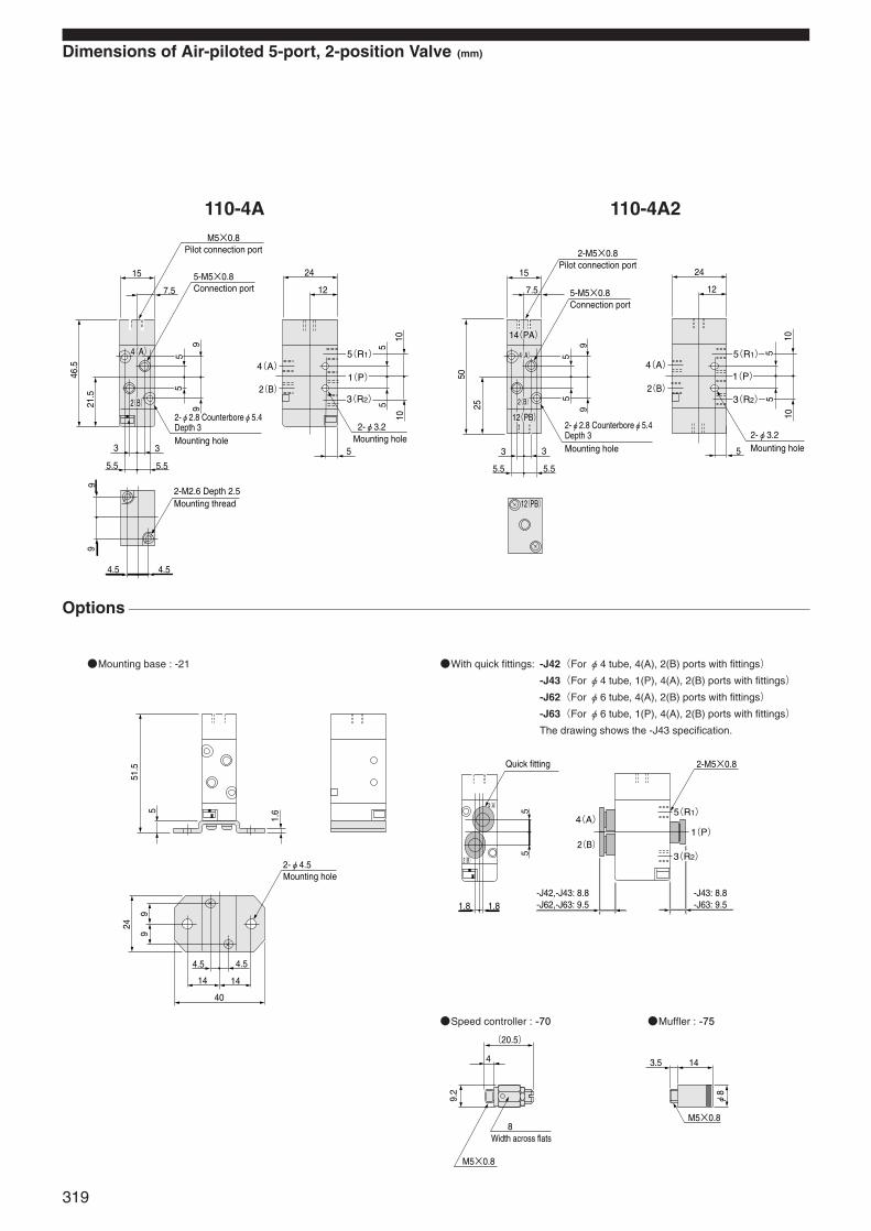
Dimensions of Air-piloted 5-port, 2-position Valve (mm)
110-4A
Options
Speed controller : -70 Muffler : -75
110-4A2
Mounting base : -21 With quick fittings: -J42(For φ4 tube, 4(A), 2(B) ports with fittings)
-J43(For φ4 tube, 1(P), 4(A), 2(B) ports with fittings)
-J62(For φ6 tube, 4(A), 2(B) ports with fittings)
-J63(For φ6 tube, 1(P), 4(A), 2(B) ports with fittings)
The drawing shows the -J43 specification.
4.5 4.5
99
15
7.5
46.5
21.5
3 3
5.55.5
99 5
55 2(B)
4(A)
5
1010
2-φ3.2
24
12
5
5(R1)
1(P)
3(R2)
4(A)
2(B)
M5×0.8Pilot connection port
5-M5×0.8Connection port
2-M2.6 Depth 2.5Mounting thread
Mounting hole
2-φ2.8 Counterboreφ5.4 Depth 3Mounting hole
15
7.5
2(B)
14(PA)
12(PB)
12(PB)
50
25
3 3
5.55.5
55
99
4(A) 55
1010
24
12
5
2(B)
4(A)5(R1)
1(P)
3(R2)
2-M5×0.8Pilot connection port
5-M5×0.8Connection port
2-φ2.8 Counterboreφ5.4 Depth 3Mounting hole
2-φ3.2Mounting hole
51.5
5
24
99
1.6
4.5
14 14
40
4.5
2-φ4.5Mounting hole
1.8 1.8
55
2-M5×0.8
2(B)
4(A)5(R1)
1(P)
4(A)
2(B) 3(R2)
Quick fitting
-J43: 8.8-J63: 9.5
-J42,-J43: 8.8-J62,-J63: 9.5
(20.5)
4
8
9.2
M5×0.8
Width across flats
3.5 14
M5×0.8
φ8
319
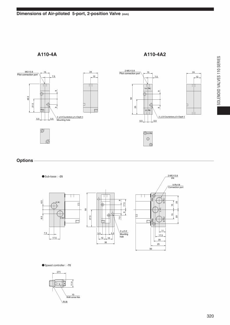
Dimensions of Air-piloted 5-port, 2-position Valve (mm)
A110-4A
Options
Sub-base : -25
A110-4A2
Speed controller : -70
M5×0.8
7.5
5.55.5
15
12
24
9
21.5
46.5
9
Pilot connection port
2-φ2.8 Counterboreφ5.4 Depth 3Mounting hole
2-M5×0.8
7.5
5.55.5
15
12
24
9
25
50
9
14(PA)
12(PB)
12(PB)
Pilot connection port
2-φ2.8 Counterboreφ5.4 Depth 3
7.5 5.5 5.5
17.5
30
12
11
17.5
20
25
50
12
6.5
6.5
55
27.5
7.5
9
917
.5
1515
PR
2
1(P)
5(R
1)
3(R
2)
PR
1
2323
5-Rc1/8
2-M5×0.8PR
2-φ3.2
2(B)
4(A)
Connection port
Mounting hole
(21)
R1/8
10
11.4
Width across flats
320
SOLE
NOID
VAL
VES
110
SERI
ES
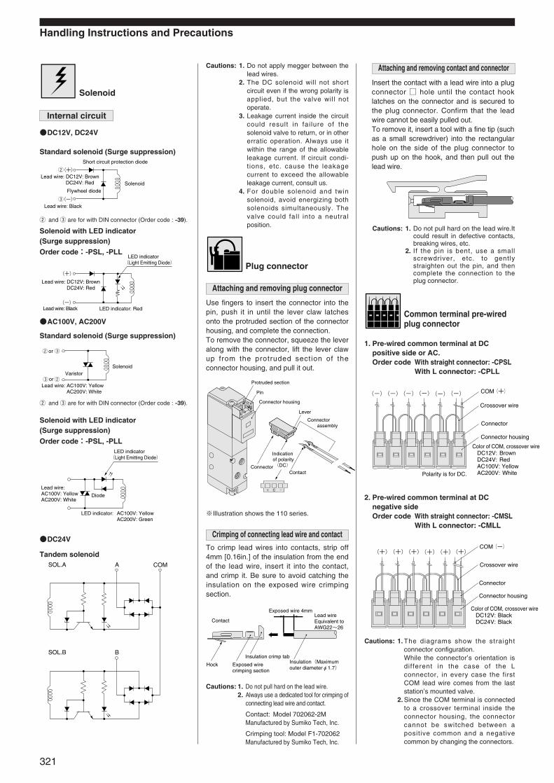
Handling Instructions and Precautions
Solenoid
DC12V, DC24V
Standard solenoid (Surge suppression)
Solenoid with LED indicator (Surge suppression)
Order code:-PSL, -PLL
AC100V, AC200V
Standard solenoid (Surge suppression)
Solenoid with LED indicator (Surge suppression)
Order code:-PSL, -PLL
Plug connector
Use fingers to insert the connector into thepin, push it in until the lever claw latchesonto the protruded section of the connectorhousing, and complete the connection.To remove the connector, squeeze the leveralong with the connector, lift the lever clawup from the protruded section of theconnector housing, and pull it out.
To crimp lead wires into contacts, strip off4mm [0.16in.] of the insulation from the endof the lead wire, insert it into the contact,and crimp it. Be sure to avoid catching theinsulation on the exposed wire crimpingsection.
Insert the contact with a lead wire into a plugconnector hole until the contact hooklatches on the connector and is secured tothe plug connector. Confirm that the leadwire cannot be easily pulled out.To remove it, insert a tool with a fine tip (suchas a small screwdriver) into the rectangularhole on the side of the plug connector topush up on the hook, and then pull out thelead wire.
Common terminal pre-wiredplug connector
1. Pre-wired common terminal at DCpositive side or AC. Order code With straight connector: -CPSL
With L connector: -CPLL
2. Pre-wired common terminal at DCnegative side Order code With straight connector: -CMSL
With L connector: -CMLL
C
Protruded section
Pin
Lever
Connector housing
Connector
Indication of polarity(DC)
Contact
Connector assembly
Hock Exposed wire crimping section
Insulation crimp tabInsulation(Maximum outer diameterφ1.7)
Lead wireEquivalent to AWG22~26
Exposed wire 4mm
Contact
※Illustration shows the 110 series.
(-)(-)(-)(-)(-)(-) COM(+)
Color of COM, crossover wire DC12V: Brown DC24V: Red AC100V: Yellow AC200V: WhitePolarity is for DC.
Crossover wire
Connector
Connector housing
(+)(+)(+)(+)(+)(+)COM(-)
Crossover wire
Connector
Connector housing
Color of COM, crossover wire DC12V: Black DC24V: Black
w and e are for with DIN connector (Order code : -39).
w and e are for with DIN connector (Order code : -39).
(+)
(-)
w
e
Short circuit protection diode
SolenoidFlywheel diode
Lead wire: DC12V: Brown
Lead wire: Black
DC24V: Red
(+)
(-)LED indicator: RedLead wire: Black
Lead wire: DC12V: Brown
LED indicator(Light Emitting Diode)
DC24V: Red
Solenoid
Lead wire: AC100V: Yellow
Varistor
orw e
e wor
AC200V: White
Lead wire:AC100V: YellowAC200V: White
AC100V: YellowAC200V: Green
LED indicator(Light Emitting Diode)
Diode
LED indicator:
321
Internal circuit
Cautions: 1. Do not apply megger between thelead wires.
2. The DC solenoid will not shortcircuit even if the wrong polarity isapplied, but the valve will notoperate.
3. Leakage current inside the circuitcould result in fai lure of thesolenoid valve to return, or in othererratic operation. Always use itwithin the range of the allowableleakage current. If circuit condi-t ions, etc. cause the leakagecurrent to exceed the allowableleakage current, consult us.
4. For double solenoid and twinsolenoid, avoid energizing bothsolenoids simultaneously. Thevalve could fal l into a neutralposition.
Attaching and removing plug connector
Crimping of connecting lead wire and contact
Cautions: 1. Do not pull hard on the lead wire.2. Always use a dedicated tool for crimping of
connecting lead wire and contact.
Contact: Model 702062-2MManufactured by Sumiko Tech, Inc.
Crimping tool: Model F1-702062Manufactured by Sumiko Tech, Inc.
Attaching and removing contact and connector
Cautions: 1. Do not pull hard on the lead wire.Itcould result in defective contacts,breaking wires, etc.
2. If the pin is bent, use a smallscrewdriver, etc. to gentlystraighten out the pin, and thencomplete the connection to theplug connector.
Cautions: 1. The diagrams show the straightconnector configuration.While the connector’s orientation isdifferent in the case of the Lconnector, in every case the firstCOM lead wire comes from the laststation’s mounted valve.
2. Since the COM terminal is connectedto a crossover terminal inside theconnector housing, the connectorcannot be switched between apositive common and a negativecommon by changing the connectors.
DC24V
Tandem solenoidA COMSOL.A
BSOL.B
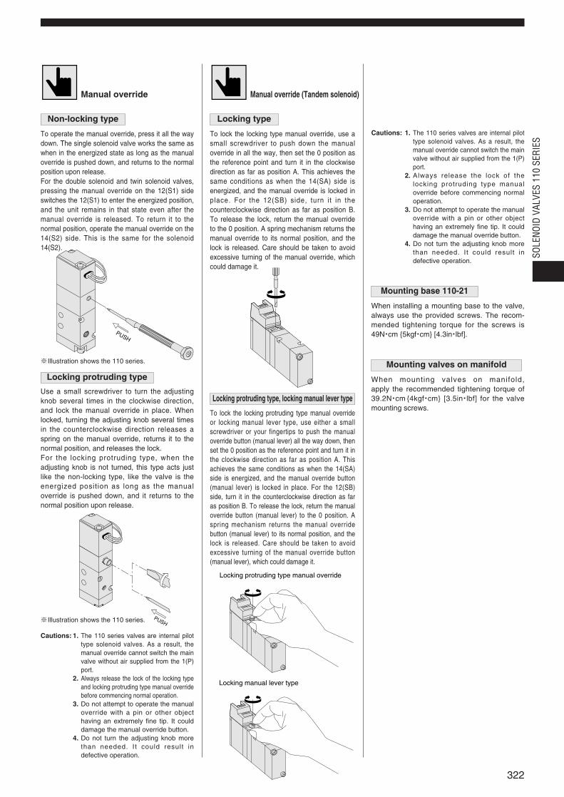
Manual override
To operate the manual override, press it all the waydown. The single solenoid valve works the same aswhen in the energized state as long as the manualoverride is pushed down, and returns to the normalposition upon release.For the double solenoid and twin solenoid valves,pressing the manual override on the 12(S1) sideswitches the 12(S1) to enter the energized position,and the unit remains in that state even after themanual override is released. To return it to thenormal position, operate the manual override on the14(S2) side. This is the same for the solenoid14(S2).
※Illustration shows the 110 series.
Use a small screwdriver to turn the adjustingknob several times in the clockwise direction,and lock the manual override in place. Whenlocked, turning the adjusting knob several timesin the counterclockwise direction releases aspring on the manual override, returns it to thenormal position, and releases the lock.For the locking protruding type, when theadjusting knob is not turned, this type acts justlike the non-locking type, like the valve is theenergized position as long as the manualoverride is pushed down, and it returns to thenormal position upon release.
※Illustration shows the 110 series.
Manual override (Tandem solenoid)
To lock the locking type manual override, use asmall screwdriver to push down the manualoverride in all the way, then set the 0 position asthe reference point and turn it in the clockwisedirection as far as position A. This achieves thesame conditions as when the 14(SA) side isenergized, and the manual override is locked inplace. For the 12(SB) side, turn it in thecounterclockwise direction as far as position B.To release the lock, return the manual overrideto the 0 position. A spring mechanism returns themanual override to its normal position, and thelock is released. Care should be taken to avoidexcessive turning of the manual override, whichcould damage it.
To lock the locking protruding type manual overrideor locking manual lever type, use either a smallscrewdriver or your fingertips to push the manualoverride button (manual lever) all the way down, thenset the 0 position as the reference point and turn it inthe clockwise direction as far as position A. Thisachieves the same conditions as when the 14(SA)side is energized, and the manual override button(manual lever) is locked in place. For the 12(SB)side, turn it in the counterclockwise direction as faras position B. To release the lock, return the manualoverride button (manual lever) to the 0 position. Aspring mechanism returns the manual overridebutton (manual lever) to its normal position, and thelock is released. Care should be taken to avoidexcessive turning of the manual override button(manual lever), which could damage it.
BA
Locking protruding type manual override
Locking manual lever type
PUSH
PUSH
322
SOLE
NOID
VAL
VES
110
SERI
ES
Locking typeNon-locking type
Locking protruding type, locking manual lever type
Locking protruding type
Cautions: 1. The 110 series valves are internal pilottype solenoid valves. As a result, themanual override cannot switch the mainvalve without air supplied from the 1(P)port.
2. Always release the lock of the locking typeand locking protruding type manual overridebefore commencing normal operation.
3. Do not attempt to operate the manualoverride with a pin or other objecthaving an extremely fine tip. It coulddamage the manual override button.
4. Do not turn the adjusting knob morethan needed. It could result indefective operation.
Mounting base 110-21
When installing a mounting base to the valve,always use the provided screws. The recom-mended tightening torque for the screws is49N・cm 5kgf・cm [4.3in・lbf].
Mounting valves on manifold
When mounting valves on manifold, apply the recommended tightening torque of39.2N・cm 4kgf・cm [3.5in・lbf] for the valvemounting screws.
Cautions: 1. The 110 series valves are internal pilottype solenoid valves. As a result, themanual override cannot switch the mainvalve without air supplied from the 1(P)port.
2. Always release the lock of thelocking protruding type manualoverride before commencing normaloperation.
3. Do not attempt to operate the manualoverride with a pin or other objecthaving an extremely fine tip. It coulddamage the manual override button.
4. Do not turn the adjusting knob morethan needed. It could result indefective operation.
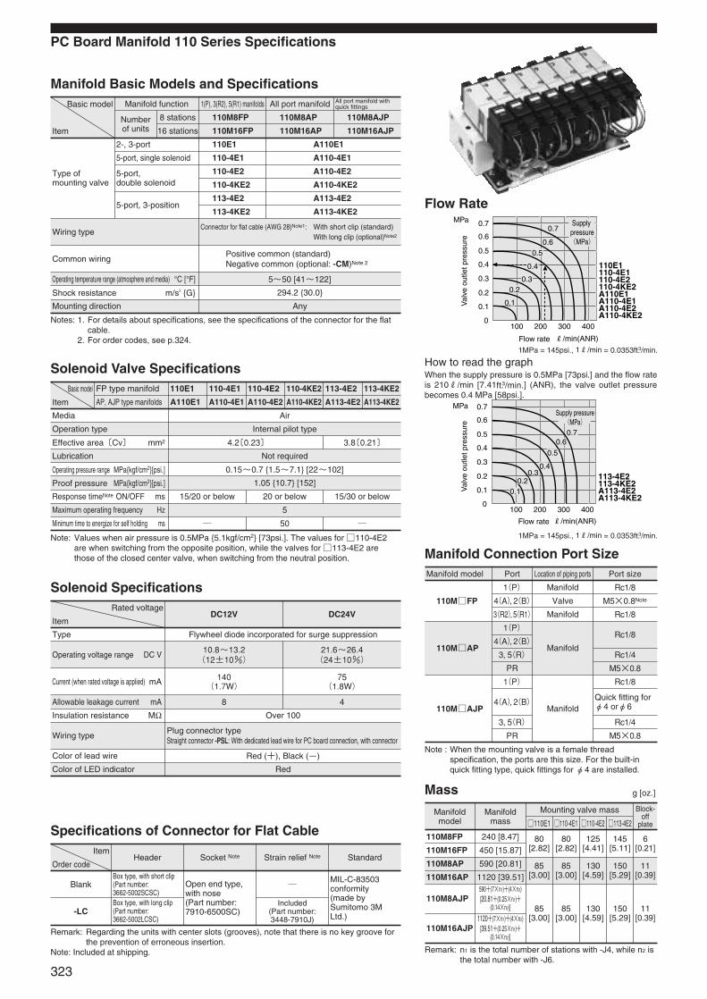
110E1110-4E1110-4E2110-4KE2A110E1A110-4E1A110-4E2A110-4KE2
0.7
0.60.5
0.4
0.30.2
0.1
0.7
0.6
0.5
0.4
0.3
0.2
0.1
0100 200 300 400
MPa
Flow rate R/min(ANR)
Supply pressure(MPa)
Val
ve o
utle
t pre
ssur
e
Manifoldmodel
Manifoldmass
Mounting valve mass
110E1 110-4E1 110-4E2 113-4E2
Block-off
plate
110M8FP 240 [8.47]
110M16FP 450 [15.87]80
[2.82]80
[2.82]125
[4.41]145
[5.11]6
[0.21]
110M8AJP590+(7×n1)+(4×n2)[20.81+(0.25×n1)+
(0.14×n2)]
110M16AJP1120+(7×n1)+(4×n2)
[39.51+(0.25×n1)+(0.14×n2)]
85[3.00]
85[3.00]
130[4.59]
150[5.29]
11[0.39]
110M8AP 590 [20.81]
110M16AP 1120 [39.51]85
[3.00]85
[3.00]130
[4.59]150
[5.29]11
[0.39]
110MFP
110MAJP
1(P) Manifold Rc1/8
M5×0.8Note
Rc1/8
Rc1/8
Quick fitting forφ4 orφ6
Rc1/4
M5×0.8
Valve
Manifold
Manifold
4(A),2(B)
3(R2),5(R1)
1(P)
4(A),2(B)
3, 5(R)
PR
110MAP
Rc1/8
Rc1/4
M5×0.8
Manifold
1(P)
4(A),2(B)
3, 5(R)
PR
Manifold model Port Location of piping ports Port size
Operating voltage range DC V10.8~13.2(12±10%)
21.6~26.4(24±10%)
Allowable leakage current mA 8
Wiring typePlug connector typeStraight connector -PSL: With dedicated lead wire for PC board connection, with connector
Color of LED indicator Red
4
Type Flywheel diode incorporated for surge suppression
Current (when rated voltage is applied) mA 140(1.7W)
75(1.8W)
Insulation resistance MΩ Over 100
Color of lead wire
Blank
-LC
Box type, with short clip(Part number:3662-5002SCSC)Box type, with long clip(Part number:3662-5002LCSC)
Open end type,with nose(Part number:7910-6500SC)
Included (Part number:3448-7910J)
MIL-C-83503conformity(made bySumitomo 3MLtd.)
Red (+), Black (-)
4.2〔0.23〕 3.8〔0.21〕
Basic model
Item
FP type manifold 110E1
DC12V DC24V
110-4E1 110-4E2 110-4KE2 113-4E2 113-4KE2
AP, AJP type manifolds A110E1 A110-4E1 A110-4E2 A110-4KE2 A113-4E2 A113-4KE2
Operation type
Lubrication
Proof pressure MPakgf/cm2[psi.]
Maximum operating frequency Hz
Not required
1.05 10.7 [152]
5
Wiring typeConnector for flat cable (AWG 28)Note1: With short clip (standard)
With long clip (optional)Note2
Positive common (standard)Negative common (optional: -CM)Note 2
5~50 [41~122]
294.2 30.0
Any
Common wiring
Operating temperature range (atmosphere and media) °C [°F]
Shock resistance m/s2 G
Air
Internal pilot type
Media
Effective area〔Cv〕 mm2
Operating pressure range MPakgf/cm2[psi.]
Response timeNote ON/OFF ms
Minimum time to energize for self holding ms
Mounting direction
A110-4E1
A110-4E2
A110-4KE2
A113-4E2
A113-4KE2
Basic model
Item
2-, 3-port
5-port, single solenoid
5-port, double solenoid
5-port, 3-position
Manifold function 1(P), 3(R2), 5(R1) manifolds
110M8FP
110M16FP
All port manifold
110M8AP
110M16AP
All port manifold withquick fittings
110M8AJP
110M16AJP
110E1
110-4E1
110-4E2
110-4KE2
113-4E2
113-4KE2
A110E1
Numberof units
8 stations
16 stations
PC Board Manifold 110 Series Specifications
Type ofmounting valve
Manifold Basic Models and Specifications
Flow Rate
Solenoid Valve Specifications
0.15~0.7 1.5~7.1 [22~102]
15/20 or below 20 or below 15/30 or below
50
Rated voltage
Item
Solenoid Specifications
Item
Order codeHeader Socket Note Strain relief Note Standard
Specifications of Connector for Flat Cable
Notes: 1. For details about specifications, see the specifications of the connector for the flatcable.
2. For order codes, see p.324.
Note: Values when air pressure is 0.5MPa 5.1kgf/cm2 [73psi.]. The values for 110-4E2are when switching from the opposite position, while the valves for 113-4E2 arethose of the closed center valve, when switching from the neutral position.
Note : When the mounting valve is a female threadspecification, the ports are this size. For the built-inquick fitting type, quick fittings for φ4 are installed.
Remark: n1 is the total number of stations with -J4, while n2 isthe total number with -J6.
Remark: Regarding the units with center slots (grooves), note that there is no key groove forthe prevention of erroneous insertion.
Note: Included at shipping.
How to read the graphWhen the supply pressure is 0.5MPa [73psi.] and the flow rateis 210R/min [7.41ft.3/min.] (ANR), the valve outlet pressurebecomes 0.4 MPa [58psi.].
Manifold Connection Port Size
Mass g [oz.]
323
1MPa = 145psi., 1R/min = 0.0353ft.3/min.
1MPa = 145psi., 1R/min = 0.0353ft.3/min.
113-4E2113-4KE2A113-4E2A113-4KE2
0.7
0.6
0.5
0.4
0.3
0.2
0.1
0100 200 300 400
Flow rate R/min(ANR)
MPa
0.70.6
0.5
0.40.3
0.20.1Val
ve o
utle
t pre
ssur
e
Supply pressure(MPa)
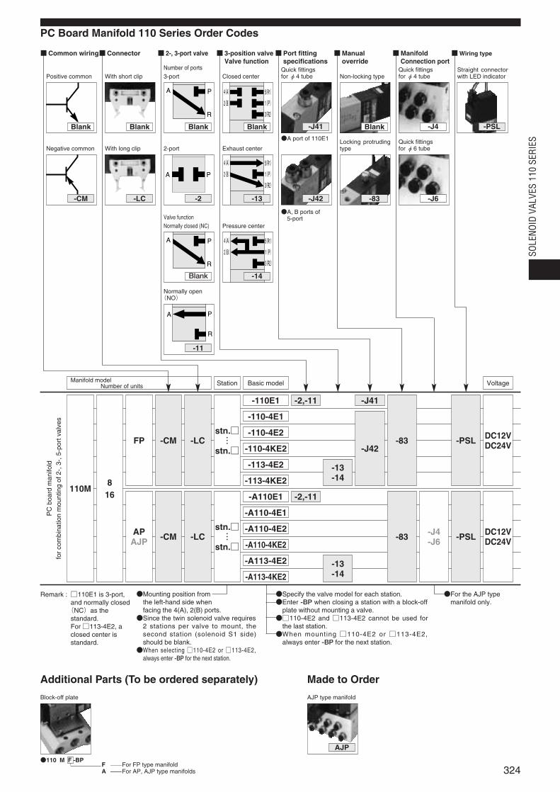
PC Board Manifold 110 Series Order Codes
Common wiring
VoltageManifold modelNumber of units Station Basic model
Positive common
Negative common
-CM
With long clip
-LC
A P
2-port
-2
4(A)
2(B)
5(R1)
3(R2)
1(P)
Exhaust center
-13 -J42
Locking protrudingtype
-83
Quick fittings for φ6 tube
Connector
With short clip
2-, 3-port valve
A P
R
Number of ports3-port
A P
R
Normally open(NO)
-11
A P
R
Valve functionNormally closed (NC)
Blank
4(A)
2(B)
5(R1)
3(R2)
1(P)
Pressure center
-14
3-position valveValve function
4(A)
2(B)
5(R1)
3(R2)
1(P)
Closed center
Port fittingspecifications
Quick fittings for φ4 tube
-J41
Manualoverride
Non-locking type
ManifoldConnection port
Quick fittings for φ4 tube
Wiring type
Straight connectorwith LED indicator
-PSL
Remark :⦆110E1 is 3-port,and normally closed(NC)as thestandard. For 113-4E2, aclosed center isstandard.
DC12V DC24V
110M
PC
boar
dm
anifo
ldfo
rco
mbi
natio
nm
ount
ing
of2-
,3-,
5-po
rtva
lves
816
FP
APAJP
-CM
-CM
-LC
-LC
stn.…
stn.
-110E1 -2,-11 -J41
-J42
-2,-11
-13-14
-13-14
-110-4E1
-110-4E2
-110-4KE2
-113-4E2
-113-4KE2
-A110E1
-A110-4E1
-A110-4E2
-A110-4KE2
-A113-4E2
-A113-4KE2
stn.…
stn.
DC12V DC24V
-PSL
-PSL-J4-J6-83
-83
A port of 110E1
A, B ports of 5-port
Specify the valve model for each station.Enter -BP when closing a station with a block-off
plate without mounting a valve.110-4E2 and 113-4E2 cannot be used for
the last station.When mounting 110-4E2 or 113-4E2,
always enter -BP for the next station.
For the AJP typemanifold only.
Mounting position from the left-hand side whenfacing the 4(A), 2(B) ports.Since the twin solenoid valve requires
2 stations per valve to mount, thesecond station (solenoid S1 side)should be blank.When selecting 110-4E2 or 113-4E2,
always enter -BP for the next station.
Additional Parts (To be ordered separately)
Block-off plate
Made to Order
AJP type manifold
AJP
110 M F -BPF For FP type manifold A For AP, AJP type manifolds
Blank
-J6
Blank Blank Blank Blank -J4
324
SOLE
NOID
VAL
VES
110
SERI
ES
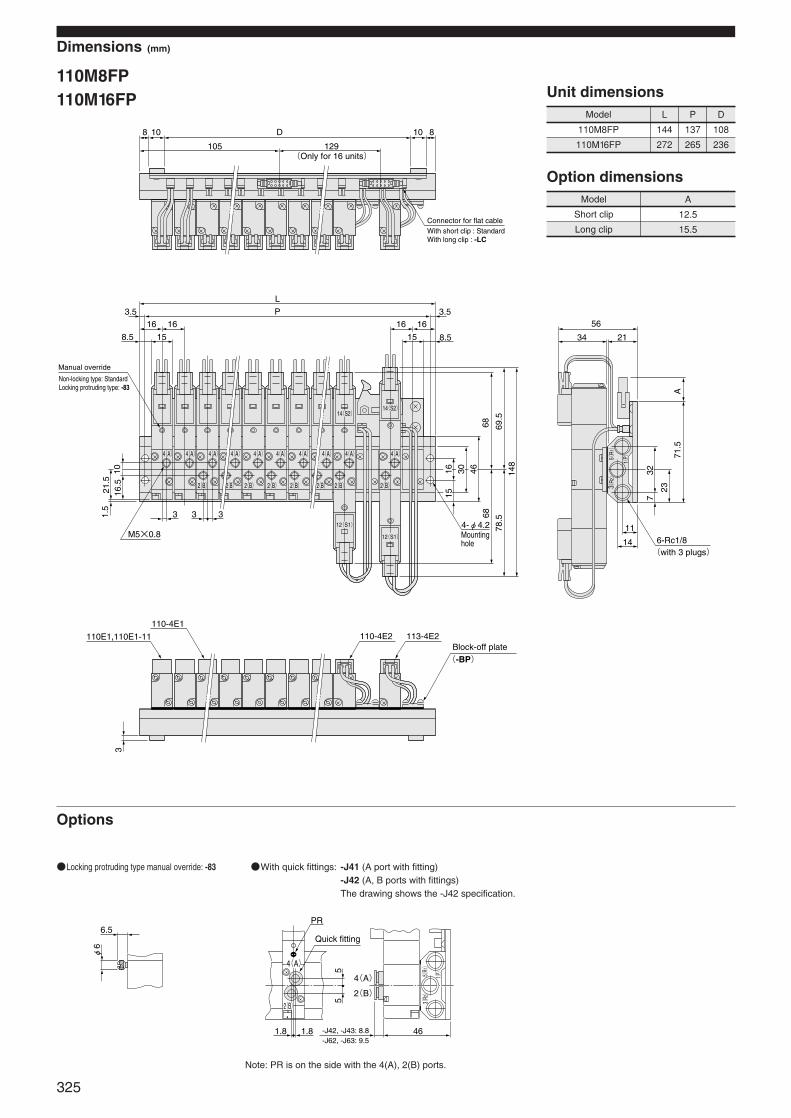
Dimensions (mm)
110M8FP110M16FP
Model L P D
110M8FP 144 137 108
110M16FP 272 265 236
Unit dimensions
Model A
Short clip 12.5
Long clip 15.5
Option dimensions
Options
Locking protruding type manual override: -83 With quick fittings: -J41 (A port with fitting)-J42 (A, B ports with fittings)The drawing shows the -J42 specification.
Note: PR is on the side with the 4(A), 2(B) ports.
D
L
P3.516 16
8.5
3 3 3
10108 8
129105
15
16 163.5
8.5
148
78.5
69.5
6868
461615 7
32
23
71.5
A
21.5
1.5
316
.510 30
15
4-φ4.2M5×0.8
4(A)4(A)4(A) 4(A) 4(A) 4(A) 4(A) 4(A) 4(A) 4(A)
2(B)2(B)2(B)2(B)2(B)2(B)2(B)2(B)
12(S1)
12(S1)
14(S2)14(S2)
113-4E2110-4E2110-4E1
110E1,110E1-11
56
34 21
11
14
1(P)
3(R2)
5(R1)
(Only for 16 units)
(-BP)
6-Rc1/8(with 3 plugs)
Manual override
Non-locking type: StandardLocking protruding type: -83
Mounting hole
Block-off plate
With short clip : StandardWith long clip : -LC
Connector for flat cable
6.5
φ6
PR
1.8 1.8 46
55
2(B)
4(A)
3(R2)
5(R1)
1(P)
4(A)
2(B)
Quick fitting
-J42, -J43: 8.8-J62, -J63: 9.5
325
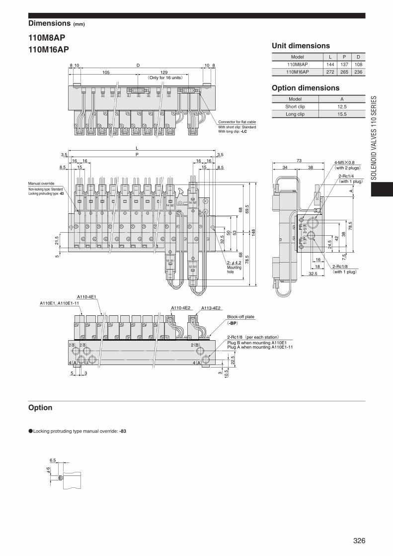
Dimensions (mm)
110M8AP110M16AP
Model L P D
110M8AP 137 108
110M16AP 272 265 236
Unit dimensions
Model A
Short clip 12.5
Long clip 15.5
Option dimensions
144
Option
Locking protruding type manual override: -83
D
L
P3.516 16
8.5
10108 8
129105
15
16 163.5
8.5
148
78.5
69.5
6868
53
32.5
7.5
42
PR
2P
R1
1(P)3・
5(R)
24.5
38
78.5
A
21.5
5
3
10.5
22.5
50
15
2-φ4.212(S1)
14(S2)
12(S1)
14(S2)
A113-4E2A110-4E2
A110-4E1
A110E1, A110E1-11
73
34 38
16
18
32.5
35
2(B)2(B) 2(B)
4(A)4(A) 4(A)
With short clip: StandardWith long clip: -LC
(Only for 16 units)
(-BP)
2-Rc1/4(with 1 plug)
2-Rc1/8(with 1 plug)
4-M5×0.8(with 2 plugs)
2-Rc1/8(per each station)
Connector for flat cable
Manual override
Non-locking type: StandardLocking protruding type: -83
Mounting hole
Block-off plate
Plug B when mounting A110E1Plug A when mounting A110E1-11
6.5
φ6
326
SOLE
NOID
VAL
VES
110
SERI
ES
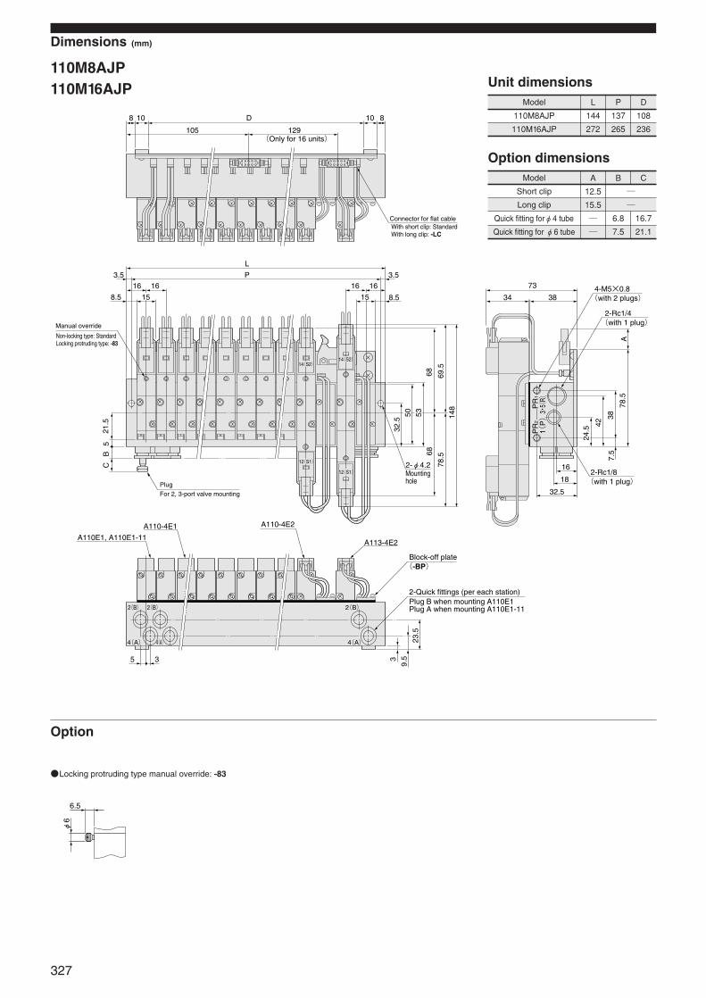
Dimensions (mm)
110M8AJP110M16AJP
Model L P D
110M8AJP 144 137 108
110M16AJP 272 265 236
Unit dimensions
Option
Locking protruding type manual override: -83
Model A B C
Short clip 12.5
Long clip 15.5
Quick fitting forφ4 tube 6.8 16.7
Quick fitting for φ6 tube 7.5 21.1
Option dimensions
2(B)2(B) 2(B)
D
L
P3.516 16
8.5
10108 8
129105
15
16 163.5
8.5
148
78.5
69.5
6868
53
32.5
7.5
42
24.5
38
78.5
A
21.5
B5
C
3
9.5
23.5
50
15
2-φ4.212(S1)
14(S2)
12(S1)
14(S2)
A113-4E2
A110-4E2A110-4E1
A110E1, A110E1-11
73
34 38
16
18
32.5
35
PR
1
1(P)3・
5(R)
PR
2
4(A) 4(A)4(A)
Connector for flat cableWith short clip: StandardWith long clip: -LC
(Only for 16 units)
Mounting hole
Manual override
Non-locking type: StandardLocking protruding type: -83
Block-off plate(-BP)
2-Rc1/4(with 1 plug)
2-Rc1/8(with 1 plug)
4-M5×0.8(with 2 plugs)
2-Quick fittings (per each station)
Plug
For 2, 3-port valve mounting
Plug B when mounting A110E1Plug A when mounting A110E1-11
6.5
φ6
327
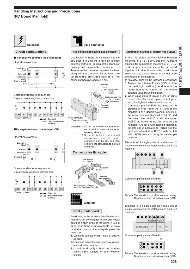
Handling Instructions and Precautions (PC Board Manifold)
Solenoid
For positive common type (standard)
Operation example
Correspondence to sequencerOutput module is negative common type.
For negative common type (optional: -CM)
Operation example
Correspondence to sequencerOutput module is positive common type.
Plug connector
Use fingers to insert the connector into thepin, push it in until the lever claw latchesonto the protruded section of the connectorhousing, and complete the connection.To remove the connector, squeeze the leveralong with the connector, lift the lever clawup from the protruded section of theconnector housing, and pull it out.
Manifold
Avoid using in the locations listed below, as itmay result in deterioration of the print circuitboard or a short circuit in the wiring. If use insuch conditions is unavoidable, alwaysprovide a cover or other adequate protectivemeasures.1. Locations subject to high levels of dust or
oil mists2. Locations subject to salt, corrosive gases,
or conductive particles3. Locations directly subject to conden-
sation, direct sunlight, or other weathereffects
In the 110 series manifold for combinationmounting of 2-, 3-, 5-port, and the PC boardmanifold for combination mounting of 2-, 3-, 5-port, single solenoids can be mountedtogether with double solenoids, or with twinsolenoids, and a total number of up to 8 or 16solenoids can be mounted.In this case, observe the following precautions:1. Always use a block-off plate (-BP) to close
the next right station (the side with thehigher numbered station) of the doublesolenoid valve mounting station.
2. When using block-off plates (-BP) for somereason other than item 1, place them togeth-er on the higher numbered stations side.
3. Connector pin numbers are allocated tostations in order from the left end of themanifold. For a double solenoid mounting,the upper pins are allocated to 14(S2) andthe lower ones to 12(S1), with the upper14(S2) numbers being the smaller pinnumbers. And for a twin solenoid mounting,the left side is allocated to 14(S2) and theright side allocated to 12(S1), with the leftside 14(S2) numbers being the smaller pinnumbers.
Example of 4 single solenoid valves and 2double solenoid valves installation on an 8 unitmanifold:
Remark: The standard is positive common wiring.Negative common wiring is optional (-CM).
Example of 3 single solenoid valves and 2double solenoid valves installation on an 8 unitmanifold:
Connector pin location of 8 units:
Remark: The standard is positive common wiring.Negative common wiring is optional (-CM).
C
ConnectorLever
Indication of polarity
Dedicated lead wire for PC board connection
Connector assembly
Connector housingProtruded section
Pin
Part numberHeader
Triangle mark(first contact indication)
Socket
Flat cable(equivalent to AWG28: MAX 10m [32.8ft.])
Clip
MIL-C-83503 conformity(made by Sumitomo 3M Ltd.)
CO
M 1357
2468
CO
M 1357
246
Connector pin location of 8 units:
1 2 8 +
+
--
080201
SolenoidLead wire:
BlackControl signal
Lead wire: Red
+
-
01~08 :~
08
8
07
7
06
6
05
5
04
4
03
3
02
2
01COM
1
81Negative common
: SolenoidSequencer outputterminal
1 2 8
+-
-
080201
-
+
Solenoid
Lead wire: Black
Control signal
Lead wire: Red
+
-
01~08 : ~
08
8
07
7
06
6
05
5
04
4
03
3
02
2
01COM
1
81Positive common : Solenoid
Sequencer output terminal
328
SOLE
NOID
VAL
VES
110
SERI
ES
Circuit configurations Attaching and removing plug connector Combination mounting for different type of valves
Connector for flat cable
Cautions: 1. Do not pull hard on the lead wire.Itcould result in defective contacts,breaking wires, etc.
2. If the pin is bent, use a smallscrewdriver, etc. to gentlystraighten out the pin, and thencomplete the connection to the plugconnector.
Print circuit board
stn.1stn.2 stn.3stn.4 stn.5stn.6 stn.7stn.8
14(S2) 14(S2)
12(S1) 12(S1)
1 2 3 4 5 7
86
stn.1stn.2 stn.3 stn.4 stn.6 stn.8
14(S2)12(S1)14(S2)12(S1)
1 2 3 4 5 76

329