solenoid valve - · pdf filedoc. no.vqc5000v-omu0002 solenoid valve product name...
TRANSCRIPT

Doc. No.VQC5000V-OMU0002
Solenoid Valve
PRODUCT NAME
VQC5000Series MODEL / Series / Product Number
No.VQC5000V-OMU0002
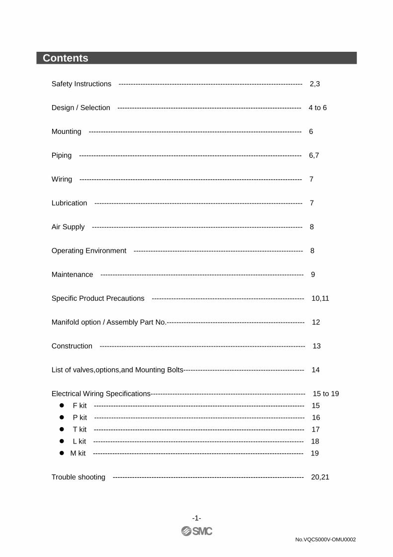
Contents
Safety Instructions ---------------------------------------------------------------------------- 2,3
Design / Selection ---------------------------------------------------------------------------- 4 to 6
Mounting ---------------------------------------------------------------------------------------- 6
Piping -------------------------------------------------------------------------------------------- 6,7
Wiring -------------------------------------------------------------------------------------------- 7
Lubrication -------------------------------------------------------------------------------------- 7
Air Supply --------------------------------------------------------------------------------------- 8
Operating Environment ---------------------------------------------------------------------- 8
Maintenance ------------------------------------------------------------------------------------ 9
Specific Product Precautions --------------------------------------------------------------- 10,11
Manifold option / Assembly Part No.--------------------------------------------------------- 12
Construction ------------------------------------------------------------------------------------- 13
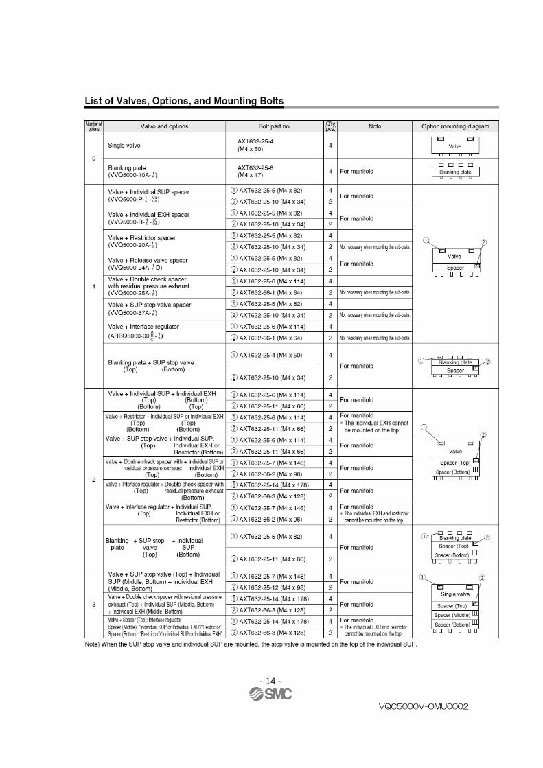
List of valves,options,and Mounting Bolts-------------------------------------------------- 14
Electrical Wiring Specifications---------------------------------------------------------------- 15 to 19
� F kit --------------------------------------------------------------------------------------- 15
� P kit --------------------------------------------------------------------------------------- 16
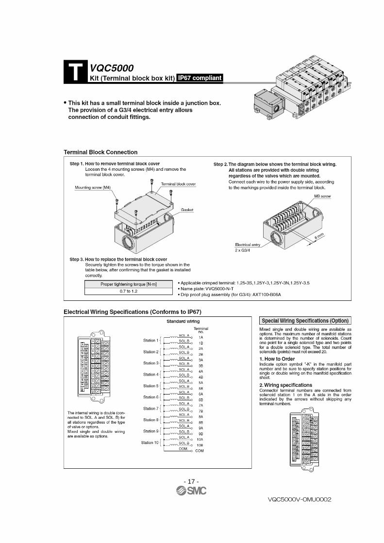
� T kit --------------------------------------------------------------------------------------- 17
� L kit --------------------------------------------------------------------------------------- 18
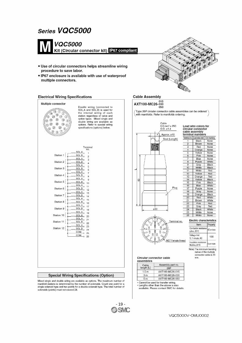
� M kit --------------------------------------------------------------------------------------- 19
Trouble shooting ------------------------------------------------------------------------------- 20,21
-1-

Safety Instructions These safety instructions are intended to prevent hazardous situations and/or equipment damage.These instructions indicate the level of potential They are all important notes for safety and must be followed in addition to International Standards(ISO/IEC)*1) , and other safety regulations*1) ISO 4414: Pneumatic fluid power -- General ISO 4413: Hydraulic fluid power -- General rules relating to systems IEC 60204-1: Safety of machinery -- ISO 10218-1992: Manipulating industrial robots etc.
Caution Cautionin minor or
Warning Warningresult in death or serious injury.
Danger Danger in death or
1. The compatibility of the product is the responsibility of the person who designs the equipment or decides its specifications. Since the product specified here is used under various operating conditions, its compatibility with specific equipment must be decided by the person who necessary analysis and test results.The expected performance and safety assurance of the equipment will be the responsibility of the person who has determined its compatibility with the productThis person should also continuously review all specifications of the product referring to its latest catalog information, with a view to giving due consideration to any possibility of equipment failure when configuring the equipment.
2. Only personnel with appropriate training should operate machinery and equipment.The product specified here may become unsafe if handled incorrectly.The assembly, operation and maintenance of machines or equipment including our products must be performed by an operator who is appropriately trained and experienced.
3. Do not service or attempt to remove product and machinery/equipment until safety is confirmed.1.The inspection and maintenance of machinery/equipment should only be performed after measures to
prevent falling or runaway of the driven objects have been confirmed.2.When the product is to be removed, confirm that the safety measures as mentioned above are implemented and the power from any appropriate source is cut, and read and understand the specific of all relevant products carefully.3. Before machinery/equipment is restarted, take measures to prevent unexpected operation and malfunction.
4. Contact SMC beforehand and take special consideration of safety measures if the product be used in any of the following conditions.1. Conditions and environments outside of the given specifications, or use outdoors or in a place exposed to direct sunlight. 2. Installation on equipment in conjunction with atomic energy, railways, air
vehicles, military, medical treatment, combustion and recreation, or equipment in contact with food and beverages, emergency stop circuits, clutch and brake circuits in press applications, safety equipment or other applications unsuitable for the standard specifications described in the product catalog.
3. An application which could have negative effects on people, property, or animals requiring special safety analysis.
4.Use in an interlock circuit, which mechanical protective function, and periodical checks to confirm proper operation.
- 2 -
Safety Instructions
These safety instructions are intended to prevent hazardous situations and/or equipment damage.These instructions indicate the level of potential hazard with the labels of “Caution,” “Warning” or “Danger.”They are all important notes for safety and must be followed in addition to International Standards
and other safety regulations. General rules relating to systems.
General rules relating to systems. Electrical equipment of machines .(Part 1: General requirements)
Manipulating industrial robots -Safety.
Caution indicates a hazard with a low level of risk which, if not avoided, could resultin minor or moderate injury.
Warning indicates a hazard with a medium level of risk which, if not avoided, coulddeath or serious injury.
indicates a hazard with a high level of risk which, if not avoided, or serious injury.
Warning product is the responsibility of the person who designs the equipment or
Since the product specified here is used under various operating conditions, its compatibility with specific equipment must be decided by the person who designs the equipment or decides its specifications based on necessary analysis and test results. The expected performance and safety assurance of the equipment will be the responsibility of the person who has determined its compatibility with the product. This person should also continuously review all specifications of the product referring to its latest catalog information, with a view to giving due consideration to any possibility of equipment failure when configuring the
with appropriate training should operate machinery and equipment.The product specified here may become unsafe if handled incorrectly. The assembly, operation and maintenance of machines or equipment including our products must be
who is appropriately trained and experienced. 3. Do not service or attempt to remove product and machinery/equipment until safety is confirmed.
The inspection and maintenance of machinery/equipment should only be performed after measures to falling or runaway of the driven objects have been confirmed.
When the product is to be removed, confirm that the safety measures as mentioned above are implementedand the power from any appropriate source is cut, and read and understand the specific of all relevant products carefully. Before machinery/equipment is restarted, take measures to prevent unexpected operation and malfunction.
4. Contact SMC beforehand and take special consideration of safety measures if the product be used in any of the following conditions.
Conditions and environments outside of the given specifications, or use outdoors or in a place exposed to
Installation on equipment in conjunction with atomic energy, railways, air navigation, space, shipping,vehicles, military, medical treatment, combustion and recreation, or equipment in contact with food andbeverages, emergency stop circuits, clutch and brake circuits in press applications, safety equipment orother applications unsuitable for the standard specifications described in the product catalog.An application which could have negative effects on people, property, or animals requiring special safety
Use in an interlock circuit, which requires the provision of double interlock for possible failure by using a mechanical protective function, and periodical checks to confirm proper operation.
No.VQC5000V-OMU0002
These safety instructions are intended to prevent hazardous situations and/or equipment damage. hazard with the labels of “Caution,” “Warning” or “Danger.”
They are all important notes for safety and must be followed in addition to International Standards
General requirements)
indicates a hazard with a low level of risk which, if not avoided, could result
level of risk which, if not avoided, could
level of risk which, if not avoided, will result
product is the responsibility of the person who designs the equipment or
Since the product specified here is used under various operating conditions, its compatibility with specific designs the equipment or decides its specifications based on
The expected performance and safety assurance of the equipment will be the responsibility of the person who
This person should also continuously review all specifications of the product referring to its latest catalog information, with a view to giving due consideration to any possibility of equipment failure when configuring the
with appropriate training should operate machinery and equipment.
The assembly, operation and maintenance of machines or equipment including our products must be
3. Do not service or attempt to remove product and machinery/equipment until safety is confirmed. The inspection and maintenance of machinery/equipment should only be performed after measures to
When the product is to be removed, confirm that the safety measures as mentioned above are implemented and the power from any appropriate source is cut, and read and understand the specific product precautions
Before machinery/equipment is restarted, take measures to prevent unexpected operation and malfunction. 4. Contact SMC beforehand and take special consideration of safety measures if the product is to
Conditions and environments outside of the given specifications, or use outdoors or in a place exposed to
navigation, space, shipping, vehicles, military, medical treatment, combustion and recreation, or equipment in contact with food and beverages, emergency stop circuits, clutch and brake circuits in press applications, safety equipment or other applications unsuitable for the standard specifications described in the product catalog. An application which could have negative effects on people, property, or animals requiring special safety
requires the provision of double interlock for possible failure by using a mechanical protective function, and periodical checks to confirm proper operation.
Safety Instructions
1.The product is provided for use in manufacturing industries.The product herein described is basically provided for peaceful use in manufacturing industries.If considering using the product in or a contract if necessary. If anything is unclear, contact your nearest sales branch.
Limited warranty and Disclaimer/Compliance RequirementsThe product used is subject to the followRequirements”. Read and accept them before using the product.
Limited warranty and Disclaimer1.The warranty period of the product is 1 year in service or 1.5 years after the product is
delivered,whichever is first.∗∗∗∗2Also, the product may have specified durability, running distance or replacement parts. Pleaseconsult your nearest sales branch.
2. For any failure or damage reported within the warranty period which is clearly our responsibility, a replacement product or necessary parts will be provided.This limited warranty applies only to our product independently, and not to any other damage
incurred due to the failure of the product. 3. Prior to using SMC products, please read and understand the warranty terms and disclaimers
noted in the specified catalog for the particular products.
∗∗∗∗2) Vacuum pads are excluded from this 1 year warranty. A vacuum pad is a consumable part, so it is warranted for a year after it is delivered.
Also, even within the warranty period, the wear of a product due to the use of the vacuumpad or failure due to the deterioration of rubber material are not covered by the limited
warranty.
Compliance Requirements1. The use of SMC products with production equipment for the manufacture of weapons of mass
destruction(WMD) or any other weapon is strictly prohibited.
2. The exports of SMC products relevant security laws and regulation of the countries involved in the transaction. Prior to the shipment of a SMC product to another country, assure that all local rules goveming that export
are known and followed.ollowed.ollowed.ollowed.
- 3 -
Safety Instructions
Caution The product is provided for use in manufacturing industries. The product herein described is basically provided for peaceful use in manufacturing industries.If considering using the product in other industries, consult SMC beforehand and exchange specifications
If anything is unclear, contact your nearest sales branch.
Limited warranty and Disclaimer/Compliance RequirementsThe product used is subject to the following “Limited warranty and Disclaimer” and “Compliance
Read and accept them before using the product.
Limited warranty and Disclaimer the product is 1 year in service or 1.5 years after the product is
2) Also, the product may have specified durability, running distance or replacement parts. Pleaseconsult your nearest sales branch.
damage reported within the warranty period which is clearly our responsibility,a replacement product or necessary parts will be provided. This limited warranty applies only to our product independently, and not to any other damage
ilure of the product.
Prior to using SMC products, please read and understand the warranty terms and disclaimers noted in the specified catalog for the particular products.
Vacuum pads are excluded from this 1 year warranty. a consumable part, so it is warranted for a year after it is delivered.
Also, even within the warranty period, the wear of a product due to the use of the vacuumpad or failure due to the deterioration of rubber material are not covered by the limited
Compliance Requirements The use of SMC products with production equipment for the manufacture of weapons of mass destruction(WMD) or any other weapon is strictly prohibited.
The exports of SMC products or technology from one country to another are govemed by the security laws and regulation of the countries involved in the transaction. Prior to the
product to another country, assure that all local rules goveming that export
No.VQC5000V-OMU0002
The product herein described is basically provided for peaceful use in manufacturing industries. other industries, consult SMC beforehand and exchange specifications
Limited warranty and Disclaimer/Compliance Requirements ing “Limited warranty and Disclaimer” and “Compliance
the product is 1 year in service or 1.5 years after the product is
Also, the product may have specified durability, running distance or replacement parts. Please
damage reported within the warranty period which is clearly our responsibility,
This limited warranty applies only to our product independently, and not to any other damage
Prior to using SMC products, please read and understand the warranty terms and disclaimers
a consumable part, so it is warranted for a year after it is delivered. Also, even within the warranty period, the wear of a product due to the use of the vacuum pad or failure due to the deterioration of rubber material are not covered by the limited
The use of SMC products with production equipment for the manufacture of weapons of mass
or technology from one country to another are govemed by the security laws and regulation of the countries involved in the transaction. Prior to the
product to another country, assure that all local rules goveming that export
- 4 -
No.VQC5000V-OMU0002
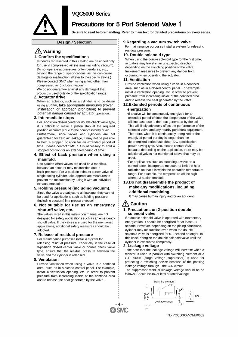
Design / Selection 1. Confirm the specifications Products represented in this catalog are designed only for use in compressed air systems (including vacuum). Do not operate at pressures or temperatures, etc., beyond the range of specifications, as this can cause damage or malfunction. (Refer to the specifications.) Please contact SMC when using a fluid other than compressed air (including vacuum). We do not guarantee against any damage if the product is used outside of the specification range.
2. Actuator drive When an actuator, such as a cylinder, is to be driven
using a valve, take appropriate measures (cover installation or approach prohibition) to prevent potential danger caused by actuator operation.
3. Intermediate stops For 3-position closed center or double check valve type,
it is difficult to make a piston stop at the required position accurately due to the compressibility of air.
Furthermore, since valves and cylinders are not guaranteed for zero air leakage, it may not be possible to hold a stopped position for an extended period of time. Please contact SMC if it is necessary to hold a stopped position for an extended period of time.
4. Effect of back pressure when using a manifold. Use caution when valves are used on a manifold, because an actuator may malfunction due to back-pressure. For 3-position exhaust center valve of single acting cylinder, take appropriate measures to prevent the malfunction by using it with an individual exhaust manifold .
5. Holding pressure (including vacuum). Since the valve are subject to air leakage, they cannot be used for applications such as holding pressure (including vacuum) in a pressure vessel.
6. Not suitable for use as an emergency shut-off valve, etc. The valves listed in this instruction manual are not designed for safety applications such as an emergency shutoff valve. If the valves are used for the mentioned applications, additional safety measures should be adopted.
7. Release of residual pressure For maintenance purposes install a system for releasing residual pressure. Especially in the case of
3-position closed center valve or double check valve type, ensure that the residual pressure between the valve and the cylinder is released.
8. Ventilation Provide ventilation when using a valve in a confined
area, such as in a closed control panel. For example, install a ventilation opening, etc. in order to prevent pressure from increasing inside of the confined area and to release the heat generated by the valve.
9.Regarding a vacuum switch valve For maintenance purposes install a system for releasing
residual pressure. 10. Double solenoid type
When using the double solenoid type for the first time, actuators may travel in an unexpected direction depending on the switching position of the valve. Implement measures to prevent any danger from occurring when operating the actuator.
11. Ventilation Provide ventilation when using a valve in a confined
area, such as in a closed control panel. For example, install a ventilation opening, etc. in order to prevent pressure from increasing inside of the confined area and to release the heat generated by the valve.
12.Extended periods of continuous energization
・If a valve will be continuously energized for an extended period of time, the temperature of the valve will increase due to the heat generated by the coil. This will likely adversely affect the performance of the solenoid valve and any nearby peripheral equipment. Therefore, when it is continuously energized or the energized period per day is longer than the de-energized period use either: DC specification, power-saving type. Also, please contact SMC because depending on the application, there may be additional valves not mentioned above that may be used.
・For applications such as mounting a valve on a control panel, incorporate measure to limit the heat radiation so that it is within the operation temperature range. For example, the temperature will be high when a 3 station manifold.
13.Do not disassemble the product of make any modifications, including
additional machining. It may cause human injury and/or an accident.
1. Precautions on 2-position double
solenoid valve If a double solenoid valve is operated with momentary
energization, it should be energized for at least 0.1 second. However, depending on the piping conditions, cylinder may malfunction even when the double solenoid valve is energized for 0.1 second or longer. In this case, energize the double solenoid valve until the cylinder is exhausted completely.
2. Leakage voltage Take note that the leakage voltage will increase when a resistor is used in parallel with switching element or a C-R circuit (surge voltage suppressor) is used for protecting a switching device because of the passing leakage voltage through the C-R circuit. The suppressor residual leakage voltage should be as follows. Should be3% or less of rated voltage.
VQC5000 Series
Precautions for 5 Port Solenoid Valve 1111
Be sure to read before handling. Refer to main text for detailed precautions on every series.
Warning
Caution

- 5 -
No.VQC5000V-OMU0002
Design / Selection
3. Surge voltage suppressor 1) A surge voltage suppressor built into the valve is
intended to protect the output contacts so that the surge generated inside valve does not adversely affect the output contacts. Therefore, if an overvoltage or overcurrent is received from an external peripheral device, the surge voltage protection element inside the valve is overloaded, causing the element to break. In the worst case, the electric circuit enters the short-circuit status by the breakage. If the energizing continues in this status, a large current flows. This may cause secondary damage to the output circuit, external peripheral device, or valve, and may also cause fire accident. So, take appropriate protective measures, such as installation of an overcurrent protection circuit in the power supply or drive circuit to maintain the sufficient safety.
2) If a surge protection circuit contains nonstandard diodes, such as Zener diodes or varistor, a residual voltage that is in proportion to the protective circuit and the rated voltage will remain. Therefore, take into consideration the surge voltage protection of the controller.In the case of diodes, the residual voltage is approximately 1 V.
4. Surge voltage intrusion With non-polar type solenoid valves, at times of sudden interruption of the loading power supply, such as emergency shutdown, surge voltage intrusion may be generated from loading equipment with a large capacity (power consumption), and the solenoid valve in a deenergized state may switch over (see Figure 1). When installing a breaker circuit for the loading power supply, consider using a solenoid valve with polarity (with polarity protection diode), or install a surge absorption diode between the loading equipment COM line and the output equipment COM line (see Figure 2).
VQC5000 Series
Precautions for 5 Port Solenoid Valve 2222
Be sure to read before handling. Refer to main text for detailed precautions on every series.
Caution

- 6 -
No.VQC5000V-OMU0002
Design / Selection
5. Operation in a low temperature
condition It is possible to operate a valve in extreme temperature, as low as -5 oC. Take appropriate measures to avoid freezing of drainage, moisture etc. in low temperature.
6. Operation for air blowing When using a solenoid valve for air blowing, use an external pilot type. Use caution because the pressure drop caused by the air blowing can have an affect on the internal pilot type valve when the internal pilot type valves and external pilot type valves are used on the same manifold. Additionally, when compressed air within the pressure range of the established specifications is supplied to the external pilot type valve’s port, and a double solenoid valve is used for air blowing, the solenoids should normally be energized when air is being blown.
7. Mounting orientation Rubber seal : Mounting orientation is free. Metal seal : Mounting orientation of a single solenoid
is universal.No specific orientation is necessary. When installing a double solenoid or a 3-position configuration, mount the valve so that spool valve is horizontal.
8. Initial lubrication of main valve The following initial lubricant has already been applied to the main valve. � Rubber seal, spool valve: Grease Please
consult with SMC, as there are some standard valve products that use fluorine grease for food processing equipment (NSF H-1).
� Metal seal, spool valve: Turbine oil Turbine oil is applied to the spool valve of a metal seal type. Therefore, turbine oil may seep out when a new product is delivered, or while the valve is stored.
Mounting
1. Operation manual Install the products and operate them only after reading the operation manual carefully and understanding its contents. Also, keep the manual where it can be referred to as necessary.
2. Ensure sufficient space for maintenance activities.
When installing the products, allow access for maintenance.
3. Tighten threads with the proper tightening torque. When installing the products, follow the listed torque specifications.
Mounting
4. If air leakage increases or equipment does not operated properly, stop operation.
Check mounting conditions when air and power supplies are connected. Initial function and leakage tests should be performed after installation.
5. Painting and coating Warnings or specifications printed or affixed to the
product should not be erased, removed or covered up. Please consult with SMC before applying paint to resinous parts, as this may have an adverse effect due to the solvent in the paint.
Piping
1. Refer to the Fittings and Tubing Precautions for handling one-touch fittings.
2. Preparation before piping Before piping is connected, it should be thoroughly
blown out with air (flushing) or washed to remove chips, cutting oil and other debris from inside the pipe.
3. Wrapping of pipe tape When screwing piping or fittings into ports, ensure that
chips from the pipe threads or sealing material do not enter the piping. Also, if pipe tape is used, leave 1 thread ridges exposed at the end of the threads.
4. Closed center For closed center, check the piping to prevent air
leakage from the piping between the valve and the cylinder.
5. Connection of fittings When screwing fittings into valves, tighten as follows.
� When using a fitting other than SMC fitting, follow the instructions given by relevant fitting manufacturer.
1) For the fitting with sealant R or NPT, first, tighten it by hand, then use a wrench appropriate for the hexagon flats of the body to tighten it a further two or three turns. For a tightening torque guide, refer to the table below.
Connection thread
size (R,NPT) Proper tightening torque
(N・・・・m)
1/8 3 to 5 1/4 8 to 12 3/8 15 to 20 1/2 20 to 25 3/4 28 to 30
Warning
Caution
VQC5000 Series
Precautions for 5 Port Solenoid Valve 3333
Be sure to read before handling. Refer to main text for detailed precautions on every series.
Caution

- 7 -
No.VQC5000V-OMU0002
Piping
3) If the fitting is tightened with excessive torque, a large
amount of sealant will seep out. Remove the excess sealant.
4) Insufficient tightening may cause seal failure, or loosen the threads.
5) Reuse (1) Normally, fittings with a sealant can be reused 2 to
3 times. (2) To prevent air leakage through the sealant, remove
any loose sealant stuck to the fitting by blowing air over the threaded portion.
(3) If the sealant no longer provides effective sealing, wrap sealing tape over the sealant before reusing. Do not use the sealant in any form other than a tape type.
(4) Once the fitting has been tightened, backing it out to its original position often causes the sealant to become defective. Air leakage will occur.
6. Uni thread fittings 1) First, tighten the threaded portion by hand, then use
a proper wrench, which could be suitable for the width across flats of the hexagon body, to tighten it further at a wrench tightening angle shown below. As a reference value for the tightening torque, refer to the table below.
Connection Female Thread: Rc, NPT, NPTF
Uni thread size
Wrench tightening angle after tightened by hand
(deg)
Tightening torque (N・m)
1/8 30 to 60 3 to 5
1/4 30 to 60 8 to 12
3/8 15 to 45 14 to 16
1/2 15 to 30 20 to 22
Connection Female Thread : G
Uni thread size
Wrench tightening angle after tightened by hand
(deg)
Tightening torque (N・m)
1/8 30 to 45 3 to 4
1/4 15 to 30 4 to 5
3/8 15 to 30 8 to 9
1/2 15 to 30 14 to 15 2) The gasket can be recycled up to 6 to 10 times. It can
be replaced easily when it has sustained damage. A broken gasket can be removed by holding it and then turning it in the same direction as loosening the thread. If gasket is difficult to remove, cut it with nippers, etc. In such a case, use caution not to scratch the seat face because the seat face of 45° gasket of fitting is t he sealing face.
7. Piping to products When piping to a product, refer to the operation manual to avoid mistakes regarding the supply port, etc.
Wiring
1. The solenoid valve is an electrical
product. For safety, install an appropriate fuse and circuit breaker before use.
1. Applied voltage When electric power is connected to a solenoid valve, be careful to apply the proper voltage. Improper voltage may cause malfunction or coil damage.
2. Check the connections. Check if the connections are correct after completing all wiring.
3. External force applied to lead wire If an excessive force is applied to the lead wire, this may cause faulty wiring. Take appropriate measures so that a force of 30 N or more is not applied to the lead wire. When instructions are given to the Specific Product Precautions, follow these specifications.
Lubrication 1. Lubrication [Rubber seal]
1) The valve has been lubricated for life by the factory and does not require any further.
2) If a lubricant is used in the system, use class 1 turbine oil (no additive), ISO VG32. For details about lubricant manufacturers’ brands, refer to SMC website. Additionally, please contact SMC for details about class 2 turbine oil (with additives) ISO VG32. Once lubricant is utilized within the system, since the original lubricant applied within the product during manufacturing will be washed away, please continue to supply lubrication to the system. Without continued lubrication, malfunctions could occur.
[Metal seal] 1) These valves can be used without lubrication. 2) If a lubricant is used in the system, use class 1
turbine oil (no additive), ISO VG32. For details about lubricant manufacturers’ brands, refer to SMC website. Additionally, please contact SMC for details about class 2 turbine oil (with additives) ISO VG32.
2. Lubrication amount If the lubrication amount is excessive, the oil may accumulate inside the pilot valve, causing malfunction or response delay. So, do not apply a large amount of oil. When a large amount of oil needs to be applied, use an external pilot type to put the supply air on the pilot valve side in the non-lube state. This prevents accumulation of oil inside the pilot valve.
VQC5000 Series
Precautions for 5 Port Solenoid Valve 4444
Be sure to read before handling. Refer to main text for detailed precautions on every series.
Caution Warning
Caution
Warning

- 8 -
No.VQC5000V-OMU0002
Air Supply
1. Type of fluids Please consult with SMC when using the product in
applications other than compressed air. 2. When there is a large amount of drainage. Compressed air containing a large amount of drainage
can cause malfunction of pneumatic equipment. An air dryer or water separator should be installed upstream from filters.
3. Drain flushing If condensation in the drain bowl is not emptied on a regular basis, the bowl will overflow and allow the condensation to enter the compressed air lines. It causes malfunction of pneumatic equipment. If the drain bowl is difficult to check and remove, installation of a drain bowl with an auto drain option is recommended.
For compressed air quality, refer to SMC’s Best Pneumatics catalog. 4. Use clean air
Do not use compressed air that contains chemicals, synthetic oils including organic solvents, salt or corrosive gasses, etc., as it can cause damage or malfunction.
1. When extremely dry air is used as the fluid, degradation of the lubrication properties in side the equipment may occur, resulting in reduced reliability (or reduced service life) of the equipment. Please consult with SMC.
2. Install an air filter. Install an air filter upstream near the valve. Select an air filter with a filtration size of 5 µm or smaller.
3. Take measures to ensure air quality, such as by installing an aftercooler, air dryer, or water separator. Compressed air that contains a large amount of drainage can cause malfunction of pneumatic equipment such as valves. Therefore, take appropriate measures to ensure air quality, such as by providing an aftercooler, air dryer, or water separator.
4. If excessive carbon powder is seen, install a mist separator on the upstream side of the valve. If excessive carbon dust is generated by the compressor, it may adhere to the inside of a valve and cause it to malfunction. For compressed air quality, refer to SMC’s Best Pneumatics catalog.
Operating Environment
1. Do not use in an atmosphere having corrosive gases, chemicals, sea water, water, water steam, or where there is direct contact with any of these .
2. Products with IP65 and IP67 enclosures (based on IEC60529) are protected against dust and water, however, these products cannot be used in water.
3. Products compliant to IP65 and IP67 satisfy the specifications through mounting. Be sure to read the Precautions for each product.
4. Do not use in an environment where flammable gas or explosive gas exists. Usage may cause a fire or explosion. The products do not have an explosion proof construction.
5. Do not use in a place subject to heavy vibration and/or shock.
6. The valve should not be exposed to prolonged sunlight. Use a protective cover.
7. Remove any sources of excessive heat. 8. If it is used in an environment where there is
possible contact with oil, weld spatter, etc., exercise preventive measures.
9. When the valve is mounted in a control panel or its energized for a long time, make sure ambient temperatures is within the specification of the valve.
1. Temperature of ambient environment Use the valve within the range of the ambient temperature specification of each valve. In addition, pay attention when using the valve in environments where the temperature changes drastically.
2. Humidity of ambient environment � When using the valve in environments with low
humidity, take measures to prevent static. � If the humidity rises, take measures to prevent the
adhesion of water droplets on the valve.
Warning
Caution
Warning
VQC5000 Series
Precautions for 5 Port Solenoid Valve 5555
Be sure to read before handling. Refer to main text for detailed precautions on every series.
Caution
- 9 -
No.VQC5000V-OMU0002
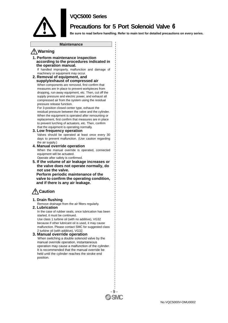
Maintenance
1. Perform maintenance inspection according to the procedures indicated in the operation manual. If handled improperly, malfunction and damage of machinery or equipment may occur.
2. Removal of equipment, and supply/exhaust of compressed air When components are removed, first confirm that measures are in place to prevent workpieces from dropping, run-away equipment, etc. Then, cut off the supply pressure and electric power, and exhaust all compressed air from the system using the residual pressure release function. For 3-position closed center type, exhaust the residual pressure between the valve and the cylinder. When the equipment is operated after remounting or replacement, first confirm that measures are in place to prevent lurching of actuators, etc. Then, confirm that the equipment is operating normally.
3. Low frequency operation Valves should be operated at least once every 30 days to prevent malfunction. (Use caution regarding the air supply.)
4. Manual override operation When the manual override is operated, connected equipment will be actuated. Operate after safety is confirmed.
5. If the volume of air leakage increases or the valve does not operate normally, do not use the valve. Perform periodic maintenance of the valve to confirm the operating condition, and if there is any air leakage.
1. Drain flushing
Remove drainage from the air filters regularly. 2. Lubrication
In the case of rubber seals, once lubrication has been started, it must be continued. Use class 1 turbine oil (with no additive), VG32 because if other lubricant oil is used, it may cause malfunction. Please contact SMC for suggested class 2 turbine oil (with additive), VG32.
3. Manual override operation When switching a double solenoid valve by the manual override operation, instantaneous operation may cause a malfunction of the cylinder. It is recommended that the manual override be held until the cylinder reaches the stroke end position.
Warning
Caution
VQC5000 Series
Precautions for 5 Port Solenoid Valve 6666
Be sure to read before handling. Refer to main text for detailed precautions on every series.

- 10 -
VQC5000V-OMU0002
Continuous Duty When the product is continuously energized for a long period of time (10 minutes or longer), select the low wattage type (DC specification). The AC type cannot be continuously energized for 10 minutes or longer. If anything is unclear, please contact SMC.
Manual Override
Since connected equipment will operate when the manual override is activated, confirm that conditions are safe prior to activation. � Push type(Tool required)
Push down the manual override button with a small screwdriver, etc., until it stops. The manual override will return when released.
� Locking type (Tool required) Push down the manual override button with a small flat head screwdriver until it stops, and turn it clockwise 90° to lock it. Turn it counterclockwise to release it.
� Locking type (Manual)
Push down the manual override button with a small flat head screwdriver or with your finger until it stops, and turn it clockwise 90° to lock it. Turn it countercl ockwise to release it.
Do not apply excessive torque when turning the manual override.[0.1 N·m or less]
After confirming that the gasket is installed correctly, securely tighten the mounting screws according to the tightening torque shown below.
Proper tightening torque [N.m] 1 to 1.8
Lead Wire Connection
Plug-in sub-plate (With terminal block) • If the junction cover ① of the sub-plate is removed, you
can see the plug-in type terminal block ② mounted inside the sub-plate.
• The terminal block is marked as follows.
Connect wiring to each of the power supply terminals.
Note 1) There is no polarity. It can also be used as –COM. Note 2) The sub-plate is double wired even for the VQC5100
1.
Applicable terminal: 1.25-3s, 1.25Y-3, 1.25Y-3N, 1.25Y-3.5
Valve Mounting
VQC5000 series Specific Product Precautions 1 Be sure to read this before handling

- 11 -
VQC5000V-OMU0002
Installation and Removal of Light Cover Installation / Removal of light cover ■■■■ Removal . To remove the pilot cover pull it straight off. If it is pulled
off at an angle, the pilot valve may be damaged or the protective O-ring may be scratched.
■■■■ Installation Place the cover straight over the pilot assembly so that the pilot valve is not touched, and push it until the cover hook locks without twisting the protective O-ring. (When pushed in, the hook opens and locks automatically.)
Replacement of Pilot Valve T • Removal 1) Remove the mounting screw that holds the pilot valve using a small screwdriver. • Installation 1) After confirming the gasket is correctly placed under the valve, securely tighten the bolts with the proper torque shown in the table below.
Proper tightening torque [N.m] 0.1 to 0.13
Plug Lead Type Attaching and detaching connectors • To attach a connector, hold the lever and connector unit between your fingers and insert straight onto the pins of the solenoid valve so that the lever’s pawl is pushed into the groove and locks. • To detach a connector, remove the pawl from the groove by pushing the lever downward with your thumb, and pull the connector straight out. Note) Do not pull on the lead wires with excessive force.
This can cause faulty and/or broken contacts.
Internal Wiring Specifications
・
How to Calculate the Flow Rate
For obtaining the flow rate, refer to the WEB catalog or the Best Pneumatics No. 1.
VQC5000 series Specific Product Precautions 2 Be sure to read this before handling
- 12 -
VQC5000V-OMU0002
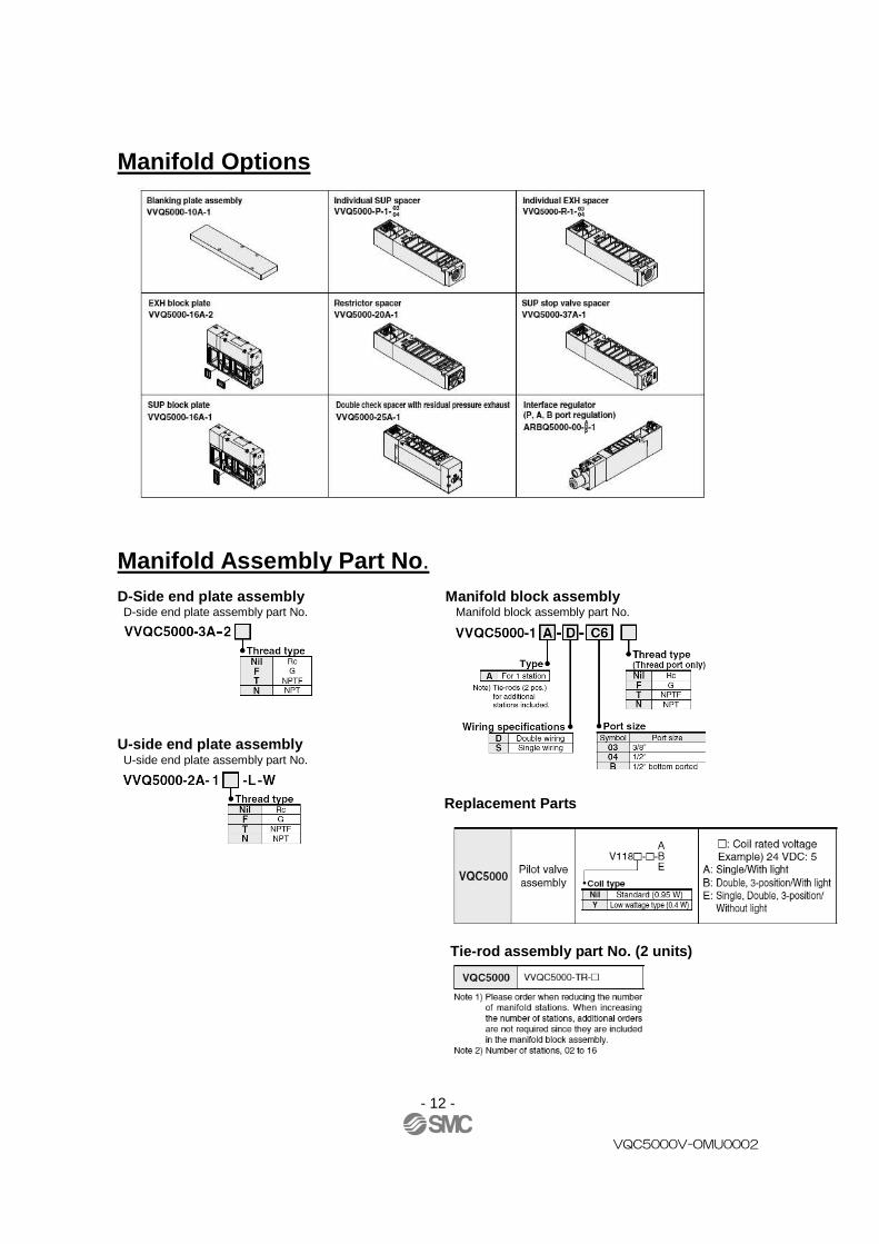
Manifold Options
Manifold Assembly Part No . D-Side end plate assembly Manifol d block assembly D-side end plate assembly part No. Manifold block assembly part No. U-side end plate assembly U-side end plate assembly part No. Replacement Parts
Tie-rod assembly part No. (2 units)

- 13 -
VQC5000V-OMU0002
Construction
- 14 -
VQC5000V-OMU0002

- 15 -
VQC5000V-OMU0002

- 16 -
VQC5000V-OMU0002
- 17 -
VQC5000V-OMU0002

- 18 -
VQC5000V-OMU0002
- 19 -
VQC5000V-OMU0002
- 20 -
No.VQC5000V-OMU0002
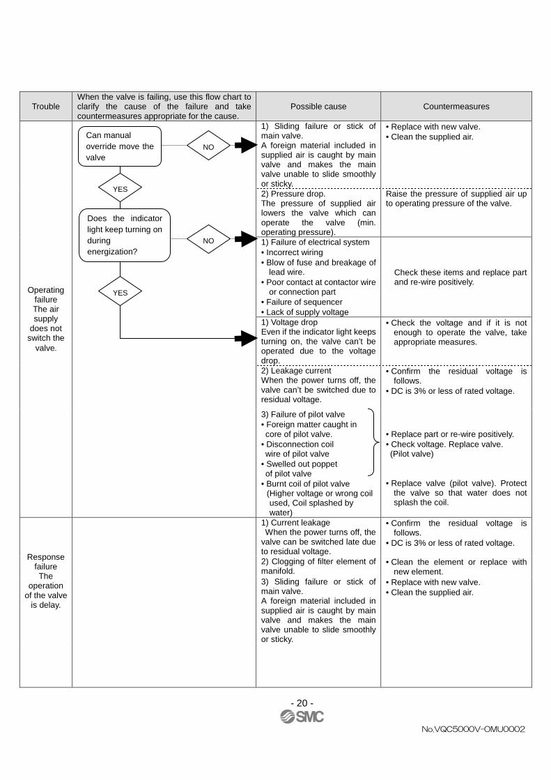
Trouble When the valve is failing, use this flow chart to clarify the cause of the failure and take countermeasures appropriate for the cause.
Possible cause Countermeasures
Operating failure The air supply
does not switch the
valve.
1) Sliding failure or stick of main valve. A foreign material included in supplied air is caught by main valve and makes the main valve unable to slide smoothly or sticky.
• Replace with new valve. • Clean the supplied air.
2) Pressure drop. The pressure of supplied air lowers the valve which can operate the valve (min. operating pressure).
Raise the pressure of supplied air up to operating pressure of the valve.
1) Failure of electrical system • Incorrect wiring • Blow of fuse and breakage of
lead wire. • Poor contact at contactor wire
or connection part • Failure of sequencer • Lack of supply voltage
Check these items and replace part and re-wire positively.
1) Voltage drop Even if the indicator light keeps turning on, the valve can’t be operated due to the voltage drop.
• Check the voltage and if it is not enough to operate the valve, take appropriate measures.
2) Leakage current When the power turns off, the valve can’t be switched due to residual voltage.
• Confirm the residual voltage is follows.
• DC is 3% or less of rated voltage.
3) Failure of pilot valve • Foreign matter caught in core of pilot valve. • Disconnection coil wire of pilot valve • Swelled out poppet of pilot valve • Burnt coil of pilot valve (Higher voltage or wrong coil
used, Coil splashed by water)
• Replace part or re-wire positively. • Check voltage. Replace valve. (Pilot valve) • Replace valve (pilot valve). Protect
the valve so that water does not splash the coil.
Response failure The
operation of the valve
is delay.
1) Current leakage When the power turns off, the valve can be switched late due to residual voltage.
• Confirm the residual voltage is follows.
• DC is 3% or less of rated voltage.
2) Clogging of filter element of manifold.
• Clean the element or replace with new element.
3) Sliding failure or stick of main valve. A foreign material included in supplied air is caught by main valve and makes the main valve unable to slide smoothly or sticky.
• Replace with new valve. • Clean the supplied air.
Can manual override move the valve
NO
YES
Does the indicator light keep turning on during energization?
NO
YES
- 21 -
No.VQC5000V-OMU0002
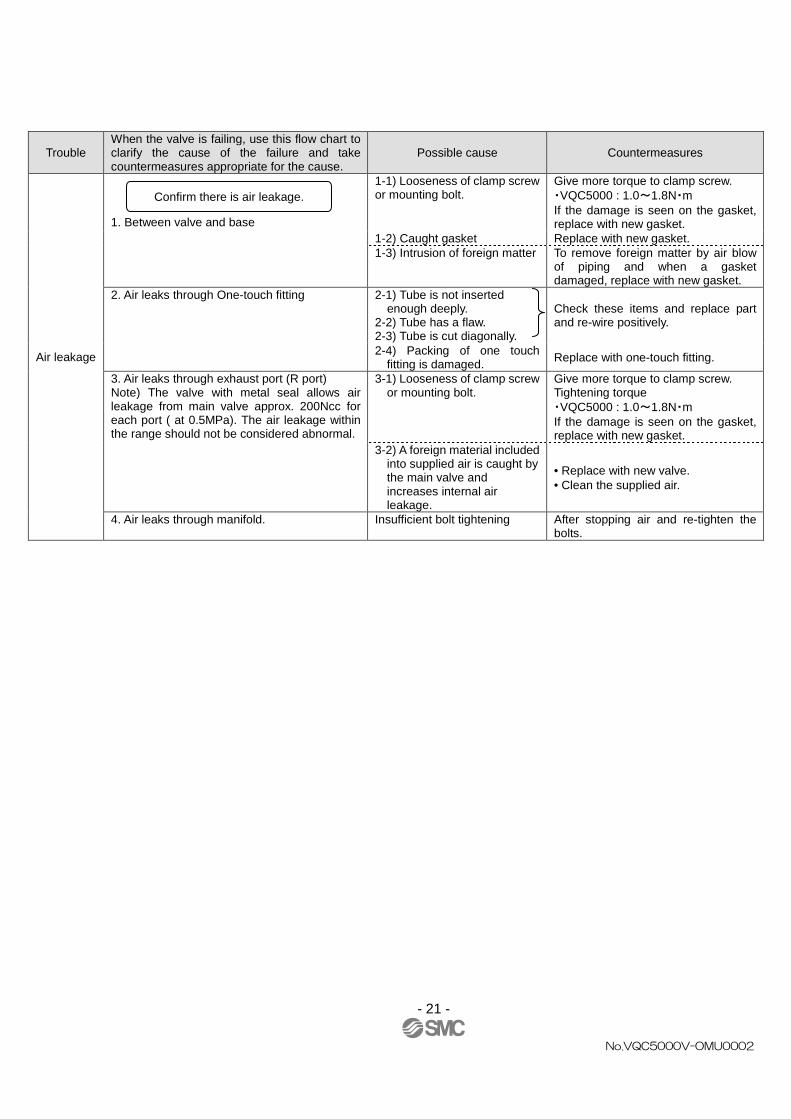
Trouble When the valve is failing, use this flow chart to clarify the cause of the failure and take countermeasures appropriate for the cause.
Possible cause Countermeasures
Air leakage
1. Between valve and base
1-1) Looseness of clamp screw or mounting bolt.
Give more torque to clamp screw. ・VQC5000 : 1.0~1.8N・m If the damage is seen on the gasket, replace with new gasket.
1-2) Caught gasket Replace with new gasket. 1-3) Intrusion of foreign matter To remove foreign matter by air blow
of piping and when a gasket damaged, replace with new gasket.
2. Air leaks through One-touch fitting 2-1) Tube is not inserted enough deeply. 2-2) Tube has a flaw. 2-3) Tube is cut diagonally.
Check these items and replace part and re-wire positively.
2-4) Packing of one touch fitting is damaged. Replace with one-touch fitting.
3. Air leaks through exhaust port (R port) Note) The valve with metal seal allows air leakage from main valve approx. 200Ncc for each port ( at 0.5MPa). The air leakage within the range should not be considered abnormal.
3-1) Looseness of clamp screw or mounting bolt.
Give more torque to clamp screw. Tightening torque ・VQC5000 : 1.0~1.8N・m If the damage is seen on the gasket, replace with new gasket.
3-2) A foreign material included into supplied air is caught by the main valve and increases internal air leakage.
• Replace with new valve. • Clean the supplied air.
4. Air leaks through manifold. Insufficient bolt tightening After stopping air and re-tighten the bolts.
Confirm there is air leakage.

No.VQC5000V-OMU0002
S
Revision history
1st printing : UT
4-14-1, Sotokanda, Chiyoda-ku, Tokyo 101-0021 JAPAN Tel: + 81 3 5207 8249 Fax: +81 3 5298 5362 URL http://www.smcworld.com Note: Specifications are subject to change without prior notice and any obligation on the part of the manufacturer. © 2011 SMC Corporation All Rights Reserved