solaris internals - maxim.int.rumaxim.int.ru/bookshelf/solarisinternals.pdf · tle matter of the...
TRANSCRIPT

SOLARIS INTERNALS
Core Kernel Components
i


SOLARIS INTERNALS
Core Kernel Components
Jim Mauro and Richard McDougall
Sun Microsystems PressA Prentice Hall Title

© 2000 Sun Microsystems, Inc. —Printed in the United States of America.901 San Antonio Road, Palo Alto, California94303 U.S.A.
All rights reserved. This product and related documentation are protected by copyright and distributedunder licenses restricting its use, copying, distribution and decompilation. No part of this product orrelated documentation may be reproduced in any form by any means without prior written authoriza-tion of Sun and its licensors, if any.
RESTRICTED RIGHTS LEGEND: Use, duplication, or disclosure by the United States Government issubject to the restrictions as set forth in DFARS 252.227-7013 (c)(1)(ii) and FAR 52.227-19.The product described in this manual may be protected by one or more U.S. patents, foreign patents, orpending applications.
TRADEMARKS—Sun, Sun Microsystems, the Sun logo, HotJava, Solaris, SunExpress, SunScreen,SunDocs, SPARC, SunOS, and SunSoft are trademarks or registered trademarks of Sun Microsystems,Inc. All other products or services mentioned in this book are the trademarks or service marks of theirrespective companies or organizations.
10 9 8 7 6 5 4 3 2 1
ISBN 0-13-022496-0
Sun Microsystems PressA Prentice Hall Title

For Traci.
.. for your love and encouragement
.......................................... Richard
For Donna, Frankie and Dominick.
All my love, always...
.......................................... Jim


ACKNOWLEDGEMENTS
It ‘s hard to thank all people that helped us with this book. As a minimum, we owe:
• Thanks to Brian Wong, Adrian Cockcroft, Paul Strong, Lisa Musgrave andFraser Gardiner for all your help and advise for the structure and content ofthis book.
• Thanks to Tony Shoumack, Phil Harman, Jim Moore, Robert Miller, MartinBraid, Robert Lane, Bert Beals, Magnus Bergman, Calum Mackay, AllanPacker, Magnus Bergman, Chris Larson, Bill Walker, Keith Bierman, DanMick and Raghunath Shenbagam for helping to review the material.
• A very special thanks to David Collier-Brown, Norm Shulman, Dominic Kay,Jarod Jenson, Bob Sneed, and Evert Hoogendoorn for painstaking page bypage reviews of the whole book.
• Our thanks to the engineers in the Solaris business unit - Jim Litchfield,Michael Shapiro, Jeff Bonwick, Wolfgang Thaler, Bryan Cantrill, RogerFaulker, Andy Tucker, Casper Dik, Tim Marsland, Andy Rudoff, Greg Onufer,Rob Gingell, Devang Shah, Deepankar Das, Dan Price and Kit Chow fortheir advise and guidance. We’re quite sure there are others, and we apolo-gize up front to those whose names we have missed.
• Thank you to the systems engineers and technical support staff at Sun for thecorrections and suggestions along the way.
• Thanks to Lou Marchant - for the endless search for engine pictures, andDwayne Schumate at Lotus Cars USA for coordinating permission to use theimages of the Lotus V8 engine.
• Thanks to the folks at Prentice Hall - Greg Doench for his patience (we didslip this thing a few times) and support.
vii

viii Acknowledgements
• Thanks to our enduring copy editor, Mary Lou Nohr for her top notch edito-rial work and style suggestions.
Without your help, this book wouldn’t be what it is today.
From Jim:
I wish to personally acknowledge Jeff Bonwick and Andy Tucker of Solaris ker-nel engineering. They demonstrated great patience in clarifying things that werecomplex to me but second nature to them. They answered innumerous emails,which contributed significantly to the accuracy of the text, as well as insuring allthe key points were made. They also provided some wonderful explanations in var-ious areas of the source code, which definitely helped.
Roger Faulkner and Jim Litchfield, also of Solaris kernel engineering, deserveand additional note of thanks for their efforts and time.
Thanks to Nobel Shelby and Casey Palowitch for reviewing sections of themanuscript and providing insightful feedback and suggestions.
I owe a debt of gratitude to Hal Stern that goes way beyond his support for thiswork. His mentoring, guidance and friendship over the years have had a profoundimpact on my development at Sun.
Last, but certainly not least, comes the family acknowledgment. This mayappear cliche’, as every technical book I’ve ever seen recognizes the writers familyin the acknowledgements section. Well, there’s a very good reason for that. Thereare only 24 hours in a day and 7 days in a week. That doesn’t change just becauseyou decide to write a book, nor do the other things that demand your time, likeyour job, your house, your lawn, etc., all of a sudden become less demanding. Sothe ones that end up getting the short end of the stick is invariably your family.Thus, my deepest gratitude goes to my wife Donna, and my sons, Frankie andDominick. Without their love, sacrifice and support, I would not have been able tocomplete this work. Thanks guys, I’m back now (of course, there is that pesky lit-tle matter of the updated version for Solaris 8...).
Jim Mauro
Green Brook, New Jersey
June, 2000

Acknowledgements ix
From Richard:
I would like to thank Adrian Cockcroft and Brian Wong for first giving me theopportunity to join their engineering group in 1995, working from my remote out-post in Australia. Their leadership and guidance has meant a lot to me during mycareer at Sun.
Thank you to our friends, visitors and family who seemingly understood for 2years when I abstained from many invites to dinners, day trips and fun events cit-ing “when the books done...”. Yes - it is done now!
And yes, a special thank you to my wife Traci, who provided a seemingly end-less amount of encouragement and personal sacrifice along the way. This projectwould have been forever unfinished without her unquestionable co-operation andsupport.
Richard McDougall
Cupertino, California
June, 2000

x Acknowledgements

PREFACE
The internals of the UNIX kernel is fairly well documented, most notably by Good-heart and Cox [10], Bach [1], McKusick et al. [19], and Vahalia [39]. These textshave become a common source of reference information for those who want to bet-ter understand the internals of UNIX. However little has been written about thespecifics of the Solaris kernel.
The paucity of Solaris specific information led us to create our own referencematerial. As we published information through white papers, magazine columns,and tutorials, the number of folks expressing interest motivated us to produce acomplete work that discussed Solaris exclusively.
About This Book
This book is about the internals of Sun’s Solaris Operating Environment. Therapid growth of Solaris has created a large number of users, software developers,systems administrators, performance analysts, and other members of the techni-cal community, all of whom require in-depth knowledge about the environment inwhich they work.
Since the focus of this book is the internals of the Solaris kernel, the book pro-vides a great deal of information on the architecture of the kernel and the majordata structures and algorithms implemented in the operating system. However,rather than approach the subject matter from a purely academic point of view, wewrote the book with an eye on the practical application of the information con-
xi

xii Preface
tained herein. Thus, we have emphasized the methods and tools that can be usedon a Solaris system to extract information that otherwise is not easily accessiblewith the standard bundled commands and utilities. We want to illustrate how youcan apply this knowledge in a meaningful way, as your job or interest dictates.
To maximize the usefulness of the text, we included specific information onSolaris versions 2.5.1, 2.6, and Solaris 7. We cover the major Solaris subsystems,including memory management, process management, threads, files, and file sys-tems. We do not cover details of low-level I/O, device drivers, STREAMS, and net-working. For reference material on these topics, see “Writing Device Drivers” [28],the “STREAMS Programming Guide” [29], and “UNIX Network Programming”[32].
The material included in this book is not necessarily presented at an introduc-tory level, although whenever possible we begin discussing a topic with some con-ceptual background information. We assume that you have some familiarity withoperating systems concepts and have used a Unix-based operating system. Someknowledge of the C programming language is useful but not required.
Because of the variety of hardware platforms on which Solaris runs, it is notpractical to discuss the low-level details of all the different processors and architec-tures, so our hardware focus, when detail is required, is admittedly UltraS-PARC-centric. This approach makes the most sense since it represents the currenttechnology and addresses the largest installed base. In general, the concepts putforth when detail is required apply to other processors and platforms supported.The differences are in the specific implementation details, such as per-processorhardware registers.
Throughout the book we refer to specific kernel functions by name as wedescribe the flow of various code segments. These routines are internal to the oper-ating system and should not be construed as, or confused with, the public inter-faces that ship as part of the Solaris product line—the systems calls and libraryinterfaces. The functions referenced throughout the text, unless explicitly noted,are private to the kernel and not callable or in any way usable by application pro-grams.
Intended Audience
We hope that this book will serve as a useful reference for a variety of technicalstaff members working with the Solaris Operating Environment.
• Application developers can find information in this book about how Solarisimplements functions behind the application programming interfaces. Thisinformation helps developers understand performance, scalability, and imple-

How This Book Is Organized xiii
mentation specifics of each interface when they develop Solaris applications.The system overview section and sections on scheduling, interprocess commu-nication, and file system behavior should be the most useful sections.
• Device driver and kernel module developers of drivers, STREAMS mod-ules, loadable system calls, etc., can find herein the general architecture andimplementation theory of the Solaris Operating Environment. The Solariskernel framework and facilities portions of the book (especially the lockingand synchronization primitives chapters) are particularly relevant.
• Systems administrators, systems analysts, database administrators,and ERP managers responsible for performance tuning and capacity plan-ning can learn about the behavioral characteristics of the major Solaris sub-systems. The file system caching and memory management chapters providea great deal of information about how Solaris behaves in real-world environ-ments. The algorithms behind Solaris tunable parameters (which are detailedin the appendix) are covered in depth throughout the book.
• Technical support staff responsible for the diagnosis, debugging and sup-port of Solaris will find a wealth of information about implementation detailsof Solaris. Major data structures and data flow diagrams are provided in eachchapter to aid debugging and navigation of Solaris Systems.
• System users who just want to know more about how the Solaris kernelworks will find high-level overviews at the start of each chapter.
In addition to the various technical staff members listed above, we also believethat members of the academic community will find the book of value in studyinghow a volume, production kernel implements major subsystems and solves theproblems inherent in operating systems development.
How This Book Is Organized
We organized Solaris Internals into several logical parts, each part grouping sev-eral chapters containing related information. Our goal was to provide a buildingblock approach to the material, where later sections build on information providedin earlier chapters. However, for readers familiar with particular aspects of operat-ing systems design and implementation, the individual parts and chapters canstand on their own in terms of the subject matter they cover.
• Part One: Introduction
• Chapter 1 — An Introduction to Solaris
• Chapter 2 — Kernel Services
• Chapter 3 — Kernel Synchronization Primitives

xiv Preface
• Chapter 4 — Kernel Bootstrap and Initialization
• Part Two: The Solaris Memory System
• Chapter 5 — Solaris Memory Architecture
• Chapter 6 — Kernel Memory
• Chapter 7 — Memory Monitoring
• Part Three: Processes, Threads, and IPC
• Chapter 8 — The Solaris Multithreaded Process Architecture
• Chapter 9 — The Solaris Kernel Dispatcher
• Chapter 10 — Interprocess Communication
• Part Four: The Solaris File I/O System
• Chapter 11 — Solaris Files and File I/O
• Chapter 12 — File System Overview
• Chapter 13 — File System Framework
• Chapter 14 — The Unix File System
• Chapter 15 — Solaris File System Cache
Solaris Source Code
In February 2000, Sun announced the availability of Solaris source. This book pro-vides the essential companion to the Solaris source and can be used as a guide tothe Solaris kernel framework and architecture.
It should also be noted that the source available from Sun is Solaris 8 source.Although this book covers Solaris versions up to and including Solaris 7, almost allof the material is relevant to Solaris 8.
Updates and Related Material
To complement this book, we created a Web site where we will place updated mate-rial, tools we refer to, and links to related material on the topics covered. The Website is available at
http://www.solarisinternals.com

Notational Conventions xv
We will regularly update the Web site with information about this text and futurework on Solaris Internals. We will place information about the differences betweenSolaris 7 and 8 at this URL, post any errors that may surface in the current edi-tion, and share reader feedback and comments and other bits of related informa-tion.
Notational Conventions
Table P-1 describes the typographic conventions used throughout the book, andTable P-2 shows the default system prompt for the utilities we describe.
Table P-1 Typographic Conventions
Typeface orSymbol
Meaning Example
AaBbCc123 Command names, filenames, and data struc-tures.
The vmstat command.
The <sys/proc.h> header file.The proc structure.
AaBbCc123() Function names. page_create_va()AaBbCc123(2) Manual pages. Please see vmstat (1M).AaBbCc123 Commands you type within
an example.$ vmstatr b w swap free re mf 0 0 0 46444018920 1 13
AaBbCc123 New terms as they areintroduced.
A major page fault occurs when…
Table P-2 Command Prompts
Shell PromptC shell prompt machine_name%C shell superuser prompt machine_name#Bourne shell and Korn shell prompt $Bourne shell and Korn shell superuser prompt #The crash utility prompt crash >

xvi Preface
A Note from the Authors
We certainly hope that you get as much out of reading Solaris Internals as we didfrom writing it. We welcome comments, suggestions, and questions from readers.We can be reached at:

CONTENTS
Acknowledgements ......................................................................... vii
Preface ................................................................................................ xi
PART ONE ........................................................ 1INTRODUCTION TO SOLARIS INTERNALS
1. An Introduction to Solaris .............................................................. 3A Brief History ....................................................................................................... 4
Key Differentiators ............................................................................................... 8
Kernel Overview ................................................................................................ 10Solaris Kernel Architecture....................................................................... 11
Modular Implementation......................................................................... 12
Processes, Threads, and Scheduling............................................................... 14Two-Level Thread Model ......................................................................... 15
Global Process Priorities and Scheduling............................................... 16
Interprocess Communication .......................................................................... 17Traditional UNIX IPC .................................................................................. 17
System V IPC ............................................................................................. 18
xvii

xviii
POSIX IPC ................................................................................................... 18
Advanced Solaris IPC............................................................................... 18
Signals ................................................................................................................. 19
Memory Management..................................................................................... 19Global Memory Allocation...................................................................... 20
Kernel Memory Management ................................................................ 21
Files and File Systems......................................................................................... 21File Descriptors and File System Calls ..................................................... 22
The Virtual File System Framework .......................................................... 23
I/O Architecture ................................................................................................ 25 2. Kernel Services ............................................................................. 27
Access to Kernel Services................................................................................. 27
Entering Kernel Mode ....................................................................................... 28Context ...................................................................................................... 29
Execution Context ........................................................................... 29
Virtual Memory Context .................................................................. 29
Threads in Kernel and Interrupt Context ................................................ 30
UltraSPARC I & II Traps .............................................................................. 31
UltraSPARC I & II Trap Types ............................................................ 32
UltraSPARC I & II Trap Priority Levels ............................................... 33
UltraSPARC I & II Trap Levels............................................................ 34
UltraSPARC I & II Trap Table Layout................................................ 34
Software Traps .................................................................................. 35
A Utility for Trap Analysis .................................................................. 36
Interrupts............................................................................................................. 38Interrupt Priorities....................................................................................... 38
Interrupts as Threads........................................................................ 39
Interrupt Thread Priorities................................................................. 41
High-Priority Interrupts ...................................................................... 41
UltraSPARC Interrupts....................................................................... 42
Interrupt Monitoring.................................................................................. 42
Interprocessor Interrupts and Cross-Calls............................................... 43
System Calls ....................................................................................................... 44Regular System Calls ................................................................................ 44
Fast Trap System Calls .............................................................................. 46
The Kernel Callout Table................................................................................... 47Solaris 2.6 and 7 Callout Tables............................................................... 47
xix
Solaris 2.5.1 Callout Tables....................................................................... 51
The System Clock .............................................................................................. 54Process Execution Time Statistics ............................................................ 55
High-Resolution Clock Interrupts ............................................................. 56
High-Resolution Timer ............................................................................... 57
Time-of-Day Clock.................................................................................... 57
3. Kernel Synchronization Primitives ............................................... 59Synchronization ................................................................................................. 59
Parallel Systems Architectures ......................................................................... 60
Hardware Considerations for Locks and Synchronization............................ 63
Introduction to Synchronization Objects ........................................................ 68Synchronization Process........................................................................... 69
Synchronization Object Operations Vector .......................................... 70
Mutex Locks ....................................................................................................... 71Overview ................................................................................................... 72
Solaris 7 Mutex Lock Implementation..................................................... 74
Solaris 2.6 Mutex Implementation Differences ............................. 78
Solaris 2.5.1 Mutex Implementation Differences .......................... 79
Why the Mutex Changes in Solaris 7.............................................. 81
Reader/Writer Locks.......................................................................................... 82Solaris 7 Reader/Writer Locks .................................................................. 83
Solaris 2.6 RW Lock Differences............................................................... 86
Solaris 2.5.1 RW Lock Differences............................................................ 86
Turnstiles and Priority Inheritance .................................................................... 89Solaris 7 Turnstiles....................................................................................... 90
Solaris 2.5.1 and 2.6 Turnstiles .................................................................. 93
Dispatcher Locks ............................................................................................... 97
Kernel Semaphores ........................................................................................... 99 4. Kernel Bootstrap and Initialization ............................................ 103
Kernel Directory Hierarchy ............................................................................. 103
Kernel Bootstrap and Initialization................................................................. 107Loading the Bootblock .......................................................................... 107
Loading ufsboot...................................................................................... 108
Locating Core Kernel Images and Linker ............................................ 109
Loading Kernel Modules ........................................................................ 109
Creating Kernel Structures, Resources, and Components ................ 110
Completing the Boot Process ............................................................... 114

xx
During the Boot Process: Creating System Kernel Threads ................ 115
Kernel Module Loading and Linking ............................................................. 116
PART TWO .................................................... 123THE SOLARIS MEMORY SYSTEM
5. Solaris Memory Architecture ..................................................... 125Why Have a Virtual Memory System?........................................................... 125
Modular Implementation ............................................................................... 128
Virtual Address Spaces ................................................................................... 130Sharing of Executables and Libraries ................................................... 132
SPARC Address Spaces.......................................................................... 132
Intel Address Space Layout................................................................... 134
Process Memory Allocation................................................................... 134
The Stack ................................................................................................. 136
Address Space Management .............................................................. 137
Virtual Memory Protection Modes........................................................ 140
Page Faults in Address Spaces ............................................................. 140
Memory Segments .......................................................................................... 143The vnode Segment: seg_vn................................................................. 147
Memory Mapped Files .................................................................. 147
Shared Mapped Files..................................................................... 150
Copy-on-Write......................................................................................... 152
Page Protection and Advice................................................................ 152
Anonymous Memory....................................................................................... 153The Anonymous Memory Layer ............................................................ 155
The swapfs Layer..................................................................................... 156
Swap Allocation............................................................................. 157
swapfs Implementation................................................................. 159
Anonymous Memory Accounting ........................................................ 161
Virtual Memory Watchpoints ......................................................................... 164
Global Page Management ........................................................................... 167Pages—The Basic Unit of Solaris Memory............................................. 167
The Page Hash List .................................................................................. 168
MMU-Specific Page Structures.............................................................. 169

xxi
Physical Page Lists .................................................................................. 170
Free List and Cache List ................................................................ 171
The Page-Level Interfaces..................................................................... 172
The Page Throttle.................................................................................... 173
Page Sizes................................................................................................ 173
Page Coloring......................................................................................... 174
The Page Scanner........................................................................................... 178Page Scanner Operation ...................................................................... 179
Page-out Algorithm and Parameters................................................... 180
Scan Rate Parameters (Assuming No Priority Paging)............... 180
Not Recently Used Time ................................................................ 182
Shared Library Optimizations................................................................. 183
The Priority Paging Algorithm ................................................................ 183
Page Scanner CPU Utilization Clamp.......................................... 185
Parameters That Limit Pages Paged Out .................................... 186
Summary of Page Scanner Parameters...................................... 186
Page Scanner Implementation ............................................................ 187
The Memory Scheduler .......................................................................... 189
Soft Swapping ................................................................................ 189
Hard Swapping .............................................................................. 190
The Hardware Address Translation Layer ..................................................... 190Virtual Memory Contexts and Address Spaces .................................. 192
Hardware Translation Acceleration............................................. 193
The UltraSPARC-I and -II HAT.................................................................. 193
Address Space Identifiers ...................................................................... 198
UltraSPARC-I and II Watchpoint Implementation ...................... 199
UltraSPARC-I and -II Protection Modes........................................ 199
UltraSPARC-I and -II MMU-Generated Traps ............................... 200
Large Pages ............................................................................................ 200
TLB Performance and Large Pages ............................................. 201
Solaris Support for Large Pages.................................................... 202
6. Kernel Memory ........................................................................... 205Kernel Virtual Memory Layout........................................................................ 205
Kernel Address Space............................................................................ 206
The Kernel Text and Data Segments .................................................... 208
Virtual Memory Data Structures............................................................ 208
The SPARC V8 and V9 Kernel Nucleus ................................................. 209
xxii
Loadable Kernel Module Text and Data ............................................. 209
The Kernel Address Space and Segments........................................... 211
Kernel Memory Allocation.............................................................................. 212The Kernel Map....................................................................................... 213
The Resource Map Allocator ................................................................ 214
The Kernel Memory Segment Driver ..................................................... 214
The Kernel Memory Slab Allocator ....................................................... 217
Slab Allocator Overview ............................................................... 217
Object Caching............................................................................. 220
General-Purpose Allocations........................................................ 223
Slab Allocator Implementation .................................................... 223
The CPU Layer ................................................................................ 225
The Depot Layer............................................................................. 225
The Global (Slab) Layer................................................................. 226
Slab Cache Parameters................................................................ 227
Slab Allocator Statistics ................................................................. 229
Slab Allocator Tracing ................................................................... 231
7. Memory Monitoring .................................................................... 235A Quick Introduction to Memory Monitoring............................................... 235
Total Physical Memory ........................................................................... 236
Kernel Memory........................................................................................ 236
Free Memory ........................................................................................... 236
File System Caching Memory................................................................ 236
Memory Shortage Detection ................................................................ 237
Swap Space............................................................................................ 238
Virtual Swap Space ....................................................................... 238
Physical Swap Space .................................................................... 238
Memory Monitoring Tools ............................................................................... 239
The vmstat Command.................................................................................... 240Free Memory ........................................................................................... 241
Swap Space............................................................................................ 241
Paging Counters..................................................................................... 242
Process Memory Usage, ps, and the pmap Command.................... 242
MemTool: Unbundled Memory Tools ............................................................ 245MemTool Utilities...................................................................................... 246
Command-Line Tools ............................................................................. 246
System Memory Summary: prtmem............................................. 246

xxiii
File System Cache Memory: memps -m ..................................... 247
The prtswap Utility .......................................................................... 248
The MemTool GUI.................................................................................... 248
File System Cache Memory .......................................................... 249
Process Memory............................................................................. 250
Process Matrix................................................................................. 252
Other Memory Tools........................................................................................ 253The Workspace Monitor Utility: WSM .................................................... 253
An Extended vmstat Command: memstat ......................................... 254
PART THREE .................................................. 259THREADS, PROCESSES, AND IPC
8. The Solaris Multithreaded Process Architecture ...................... 261Introduction to Solaris Processes ................................................................... 261
Architecture of a Process ...................................................................... 262
Process Image ........................................................................................ 267
Process Structures............................................................................................ 269The Process Structure ............................................................................. 269
The User Area .......................................................................................... 281
The Lightweight Process (LWP).............................................................. 285
The Kernel Thread (kthread).................................................................. 287
The Kernel Process Table ................................................................................ 290Process Limits........................................................................................... 291
LWP Limits................................................................................................. 293
Process Creation ............................................................................................. 293
Process Termination ........................................................................................ 302The LWP/kthread Model ........................................................................ 304
Deathrow................................................................................................. 305
Procfs — The Process File System................................................................... 306Procfs Implementation........................................................................... 309
Process Resource Usage........................................................................ 318
Microstate Accounting.......................................................................... 320
Signals ............................................................................................................... 324Signal Implementation........................................................................... 330
Synchronous Signals....................................................................... 339

xxiv
Asynchronous Signals .................................................................... 340
SIGWAITING: A Special Signal ............................................................... 342
Sessions and Process Groups ......................................................................... 342 9. The Solaris Kernel Dispatcher .................................................... 349
Overview .......................................................................................................... 350Scheduling Classes ................................................................................. 352
Dispatch Tables....................................................................................... 362
The Kernel Dispatcher..................................................................................... 368Dispatch Queues.................................................................................... 371
Thread Priorities ....................................................................................... 375
Dispatcher Functions.............................................................................. 388
Dispatcher Queue Insertion.......................................................... 388
Thread Preemption ........................................................................ 394
The Heart of the Dispatcher: swtch()........................................... 400
The Kernel Sleep/Wakeup Facility ................................................................. 404Condition Variables................................................................................ 405
Sleep Queues.......................................................................................... 407
The Sleep Process ................................................................................... 410
The Wakeup Mechanism....................................................................... 413
Scheduler Activations..................................................................................... 415User Thread Activation........................................................................... 416
LWP Pool Activation ............................................................................... 417
Kernel Processor Control and Processor Sets ............................................... 419Processor Control.................................................................................... 422
Processor Sets.......................................................................................... 425
10. Interprocess Communication ................................................. 429Generic System V IPC Support ...................................................................... 430
Module Creation .................................................................................... 430
Resource Maps ....................................................................................... 433
System V Shared Memory .............................................................................. 433Shared Memory Kernel Implementation ............................................. 438
Intimate Shared Memory (ISM) ............................................................. 440
System V Semaphores .................................................................................... 444Semaphore Kernel Resources ............................................................... 445
Kernel Implementation of System V Semaphores .............................. 448
Semaphore Operations Inside Solaris................................................... 450
System V Message Queues............................................................................ 451

xxv
Kernel Resources for Message Queues................................................ 452
Kernel Implementation of Message Queues ...................................... 457
POSIX IPC.......................................................................................................... 459POSIX Shared Memory ........................................................................... 461
POSIX Semaphores ................................................................................. 462
POSIX Message Queues......................................................................... 465
Solaris Doors ..................................................................................................... 469Doors Overview ...................................................................................... 470
Doors Implementation ........................................................................... 471
PART FOUR................................................... 479FILES AND FILE SYSTEMS
11. Solaris Files and File I/O ........................................................... 481Files in Solaris .................................................................................................... 481
Kernel File Structures............................................................................... 486
File Application Programming Interfaces (APIs) .......................................... 488Standard I/O (stdio) ............................................................................... 489
C Runtime File Handles .......................................................................... 492
Standard I/O Buffer Sizes........................................................................ 493
System File I/O.................................................................................................. 493File I/O System Calls................................................................................ 493
The open() and close() System Calls ........................................... 494
The read() and write() System Calls............................................. 494
File Open Modes and File Descriptor Flags ......................................... 495
Nonblocking I/O............................................................................. 496
Exclusive open................................................................................ 496
File Append Flag............................................................................ 497
Data Integrity and Synchronization Flags ................................... 498
Other File Flags ............................................................................... 499
The dup System Call ...................................................................... 499
The pread and pwrite System Calls ............................................. 501
The readv and writev System Calls .............................................. 502
Asynchronous I/O............................................................................................ 502File System Asynchronous I/O ............................................................... 503
Kernel Asynchronous I/O ....................................................................... 504

xxvi
Memory Mapped File I/O............................................................................... 509Mapping Options ................................................................................... 511
Mapping Files into Two or More Processes.................................. 512
Permission Options ......................................................................... 512
Providing Advice to the Memory System ............................................ 513
The MADV_DONTNEED Flag.......................................................... 513
The MADV_WILLNEED Flag ............................................................ 515
The MADV_SEQUENTIAL Flag ........................................................ 515
The MADV_RANDOM Flag ............................................................ 516
64-bit Files in Solaris.......................................................................................... 51764-bit Device Support in Solaris 2.0 ....................................................... 518
64-bit File Application Programming Interfaces in Solaris 2.5.1 ......... 518
Solaris 2.6: The Large-File OS.................................................................. 519
The Large-File Summit.................................................................... 520
Large-File Compilation Environments .......................................... 520
File System Support for Large Files ........................................................ 522
12. File System Overview ............................................................... 523Why Have a File System?................................................................................ 523
Support for Multiple File System Types .......................................................... 524
Regular (On-Disk) File Systems ....................................................................... 525Allocation and Storage Strategy.......................................................... 526
Block-Based Allocation ................................................................. 526
Extent-Based Allocation................................................................ 527
Extentlike Performance from Block Clustering............................ 528
File System Capacity.............................................................................. 529
Variable Block Size Support ................................................................... 530
Access Control Lists ................................................................................ 531
File Systems Logging (Journaling) ......................................................... 532
Metadata Logging ........................................................................ 534
Data and Metadata Logging ...................................................... 535
Log-Structured File Systems........................................................... 536
Expanding and Shrinking File Systems .................................................. 536
Direct I/O ................................................................................................. 537
Sparse Files...................................................................................... 538
Integrated Volume Management............................................... 538
Summary of File System Features ................................................. 538

xxvii
13. File System Framework ............................................................ 541Solaris File System Framework ........................................................................ 541
Unified File System Interface ................................................................. 542
File System Framework Facilities............................................................ 543
The vnode ........................................................................................................ 543vnode Types ............................................................................................ 545
Vnode Methods...................................................................................... 546
vnode Reference Count ....................................................................... 548
Interfaces for Paging vnode Cache .................................................... 548
Block I/O on vnode Pages .................................................................... 550
The vfs Object.................................................................................................. 550The File System Switch Table ................................................................. 552
The Mounted vfs List ............................................................................... 554
File System I/O.................................................................................................. 558Memory Mapped I/O............................................................................. 559
read() and write() System Calls ............................................................ 560
The seg_map Segment.......................................................................... 561
Path-Name Management ............................................................................. 565The lookupname() and lookupppn() Methods................................... 566
The vop_lookup() Method..................................................................... 566
The vop_readdir() Method .................................................................... 566
Path-Name Traversal Functions ............................................................ 568
The Directory Name Lookup Cache (DNLC) ...................................... 568
DNLC Operation ............................................................................ 569
The New Solaris DLNC Algorithm.................................................. 571
DNLC Support Functions ............................................................... 572
File System Modules................................................................................ 573
Mounting and Unmounting................................................................... 573
The File System Flush Daemon ....................................................................... 576 14. The Unix File System ................................................................. 577
UFS Development History ............................................................................... 577
UFS On-Disk Format ......................................................................................... 579UFS Inodes ............................................................................................... 579
UFS Directories......................................................................................... 579
UFS Hard Links.......................................................................................... 581
UFS Layout ............................................................................................... 581
The Boot Block................................................................................ 582

xxviii
The Superblock............................................................................... 583
Disk Block Location................................................................................. 584
UFS Block Allocation ............................................................................... 585
UFS Allocation and Parameters ............................................................ 586
UFS Implementation........................................................................................ 590Mapping of Files to Disk Blocks.............................................................. 592
Reading and Writing UFS Blocks ................................................... 592
Buffering Block Metadata............................................................. 593
Methods to Read and Write UFS Files................................................... 593
ufs_read()........................................................................................ 593
ufs_write()........................................................................................ 595
In-Core UFS Inodes.................................................................................. 597
Freeing inodes—the Inode Idle List .............................................. 598
Caching Inodes—the Inode Idle List ........................................... 598
UFS Directories and Path Names .......................................................... 600
ufs_lookup() .................................................................................... 600
ufs_readdir() ................................................................................... 600
15. Solaris File System Cache ........................................................ 601Introduction to File Caching .......................................................................... 601
Solaris Page Cache................................................................................ 602
Block Buffer Cache ................................................................................ 604
Page Cache and Virtual Memory System ................................................... 605File System Paging Optimizations ......................................................... 607
Is All That Paging Bad for My System? .......................................................... 608
Paging Parameters That Affect File System Performance.......................... 611
Bypassing the Page Cache with Direct I/O ................................................. 614UFS Direct I/O .......................................................................................... 614
Direct I/O with Veritas VxFS ................................................................... 615
Directory Name Cache.................................................................................. 615
Inode Caches.................................................................................................. 617UFS Inode Cache Size ............................................................................ 617
VxFS Inode Cache.................................................................................. 620

xxix
Appendix A Kernel Tunables, Switches, and Limits ..................... 621
Appendix B Kernel Virtual Address Maps..................................... 633
Appendix C A Sample Procfs utility............................................... 641
Bibliography...................................................................................... 647
Index ................................................................................................. 651

xxx

LIST OF FIGURES
Figure 1.1 Solaris Kernel Components ............................................................. 12 Figure 1.2 Core Kernel and Loadable Modules............................................. 13 Figure 1.3 Kernel Threads, Processes, and Lightweight Processes ............... 15 Figure 1.4 Two-Level Thread Model................................................................. 15 Figure 1.5 Global Thread Priorities.................................................................... 16 Figure 1.6 Address Spaces, Segments, and Pages........................................ 20 Figure 1.7 Files Organized in a Hierarchy of Directories ................................ 22 Figure 1.8 VFS/Vnode Architecture ................................................................. 24 Figure 1.9 The Solaris Device Tree.................................................................... 25 Figure 2.1 Switching into Kernel Mode via System Calls ............................... 28 Figure 2.2 Process, Interrupt, and Kernel Threads .......................................... 31 Figure 2.3 UltraSPARC I & II Trap Table Layout................................................ 35 Figure 2.4 Solaris Interrupt Priority Levels ......................................................... 38 Figure 2.5 Handling Interrupts with Threads .................................................... 40 Figure 2.6 Interrupt Thread Global Priorities .................................................... 41 Figure 2.7 Interrupt Table on sun4u Architectures ......................................... 42 Figure 2.8 The Kernel System Call Entry (sysent ) Table................................ 44 Figure 2.9 System Call Execution ..................................................................... 45 Figure 2.10 Solaris 2.6 and Solaris 7 Callout Tables........................................... 48 Figure 2.11 Solaris 2.5.1 Callout Tables .............................................................. 52 Figure 2.12 Time-of-Day Clock on SPARC Systems .......................................... 58 Figure 3.1 Parallel Systems Architectures ........................................................ 62 Figure 3.2 Atomic Instructions for Locks on SPARC ........................................ 65 Figure 3.3 Hardware Data Hierarchy .............................................................. 66
xxxi

xxxii
Figure 3.4 Solaris Locks — The Big Picture ....................................................... 70 Figure 3.5 Solaris 7 Adaptive and Spin Mutex ................................................ 74 Figure 3.6 Solaris 2.6 Mutex ............................................................................... 79 Figure 3.7 Solaris 2.5.1 Adaptive Mutex........................................................... 80 Figure 3.8 Solaris 2.5.1 Mutex Operations Vectoring ..................................... 80 Figure 3.9 Solaris 7 Reader/Writer Lock ........................................................... 83 Figure 3.10 Solaris 2.6 Reader/Writer Lock ........................................................ 86 Figure 3.11 Solaris 2.5.1 RW Lock Structure ....................................................... 86 Figure 3.12 Solaris 7 Turnstiles .............................................................................. 91 Figure 3.13 Solaris 2.5.1 and Solaris 2.6 Turnstiles .............................................. 93 Figure 3.14 Solaris 2.5.1 and 2.6 Turnstiles.......................................................... 94 Figure 3.15 Kernel Semaphore ........................................................................... 99 Figure 3.16 Sleep Queues in Solaris 2.5.1, 2.6, and 7 ..................................... 101 Figure 4.1 Core Kernel Directory Hierarchy .................................................. 105 Figure 4.2 Bootblock on a UFS-Based System Disk ....................................... 108 Figure 4.3 Boot Process ................................................................................... 110 Figure 4.4 Loading a Kernel Module ............................................................. 117 Figure 4.5 Module Control Structures ............................................................ 118 Figure 4.6 Module Operations Function Vectoring ..................................... 121 Figure 5.1 Solaris Virtual-to-Physical Memory Management ...................... 127 Figure 5.2 Solaris Virtual Memory Layers ....................................................... 130 Figure 5.3 Process Virtual Address Space ..................................................... 131 Figure 5.4 SPARC 32-Bit Shared Kernel/Process Address Space ................ 133 Figure 5.5 SPARC sun4u 32- and 64-Bit Process Address Space................. 134 Figure 5.6 Intel x86 Process Address Space.................................................. 135 Figure 5.7 The Address Space ........................................................................ 137 Figure 5.8 Virtual Address Space Page Fault Example ............................... 142 Figure 5.9 Segment Interface......................................................................... 144 Figure 5.10 The seg_vn Segment Driver Vnode Relationship ....................... 149 Figure 5.11 Shared Mapped Files..................................................................... 151 Figure 5.12 Anonymous Memory Data Structures ......................................... 154 Figure 5.13 Anon Slot Initialized to Virtual Swap Before Page-out............... 160 Figure 5.14 Physical Swap After a Page-out Occurs ..................................... 161 Figure 5.15 Swap Allocation States ................................................................. 163 Figure 5.16 Watchpoint Data Structures ......................................................... 167 Figure 5.17 The Page Structure ........................................................................ 168 Figure 5.18 Locating Pages by Their Vnode/Offset Identity ......................... 169 Figure 5.19 Machine-Specific Page Structures: sun4u Example .................. 170 Figure 5.20 Contiguous Physical Memory Segments..................................... 171 Figure 5.21 Physical Page Mapping into a 64-Kbyte Physical Cache......... 175 Figure 5.22 Two-Handed Clock Algorithm...................................................... 180 Figure 5.23 Page Scanner Rate, Interpolated by Number of Free Pages .. 181

xxxiii
Figure 5.24 Scan Rate Interpolation with the Priority Paging Algorithm...... 185 Figure 5.25 Page Scanner Architecture.......................................................... 188 Figure 5.26 Role of the HAT Layer in Virtual-to-Physical Translation ............. 190 Figure 5.27 UltraSPARC-I and -II MMUs ............................................................ 194 Figure 5.28 Virtual-to-Physical Translation ....................................................... 195 Figure 5.29 UltraSPARC-I and -II Translation Table Entry (TTE)........................ 196 Figure 5.30 Relationship of TLBs, TSBs, and TTEs............................................... 197 Figure 6.1 Solaris 7 64-Bit Kernel Virtual Address Space............................... 207 Figure 6.2 Kernel Address Space ................................................................... 211 Figure 6.3 Different Levels of Memory Allocation ........................................ 213 Figure 6.4 Objects, Caches, Slabs, and Pages of Memory ........................ 219 Figure 6.5 Slab Allocator Internal Implementation ...................................... 224 Figure 7.1 Process Private and Shared Mappings (/bin/sh Example) .... 244 Figure 7.2 MemTool GUI: File System Cache Memory................................. 249 Figure 7.3 MemTool GUI: Process Memory ................................................... 251 Figure 7.4 MemTool GUI: Process/File Matrix ................................................ 253 Figure 8.1 Process Execution Environment.................................................... 263 Figure 8.2 The Multithreaded Process Model ............................................... 266 Figure 8.3 ELF Object Views............................................................................ 268 Figure 8.4 Conceptual View of a Process .................................................... 269 Figure 8.5 The Process Structure and Associated Data Structures ............ 270 Figure 8.6 Process Virtual Address Space ..................................................... 271 Figure 8.7 Process State Diagram.................................................................. 275 Figure 8.8 Process Lineage Pointers............................................................... 277 Figure 8.9 PID Structure ................................................................................... 278 Figure 8.10 Process Open File Support Structures .......................................... 284 Figure 8.11 The Process, LWP, and Kernel Thread Structure Linkage........... 290 Figure 8.12 Process Creation........................................................................... 294 Figure 8.13 exec Flow....................................................................................... 299 Figure 8.14 exec Flow to Object-Specific Routine........................................ 300 Figure 8.15 Initial Process Stack Frame............................................................ 301 Figure 8.16 procfs Kernel Process Directory Entries ........................................ 310 Figure 8.17 procfs Directory Hierarchy ............................................................ 311 Figure 8.18 procfs Data Structures................................................................... 312 Figure 8.19 procfs File Open............................................................................. 313 Figure 8.20 procfs Interface Layers.................................................................. 315 Figure 8.21 Signal Representation in k_sigset_t Data Type ........................... 330 Figure 8.22 Signal-Related Structures .............................................................. 332 Figure 8.23 High-Level Signal Flow ................................................................... 339 Figure 8.24 Process Group Links ....................................................................... 344 Figure 8.25 Process and Session Structure Links.............................................. 346 Figure 9.1 Global Priority Scheme and Scheduling Classes........................ 351

xxxiv
Figure 9.2 Solaris Scheduling Classes and Priorities...................................... 354 Figure 9.3 Scheduling Class Data Structures ................................................ 362 Figure 9.4 tsproc Structure Lists .................................................................... 371 Figure 9.5 Solaris Dispatch Queues................................................................ 374 Figure 9.6 Setting RT Priorities.......................................................................... 377 Figure 9.7 Setting a Thread’s Priority Following fork() ............................... 379 Figure 9.8 Priority Adjustment with ts_slpret ............................................. 384 Figure 9.9 Kernel Thread Queue Insertion..................................................... 389 Figure 9.10 Thread Preemption Flow ............................................................... 400 Figure 9.11 Condition Variable ........................................................................ 405 Figure 9.12 Sleep/Wake Flow Diagram........................................................... 407 Figure 9.13 Solaris 2.5.1 and Solaris 2.6 Sleep Queues................................... 408 Figure 9.14 Solaris 7 Sleep Queues .................................................................. 409 Figure 9.15 Setting a Thread’s Priority in ts_sleep() ................................... 412 Figure 9.16 Two-Level Threads Model ............................................................. 415 Figure 9.17 CPU Structure and Major Links...................................................... 421 Figure 9.18 Processor Partition (Processor Set) Structures and Links ............ 427 Figure 10.1 Shared Memory: ISM versus Non-ISM........................................... 441 Figure 10.2 System V Message Queue Structures .......................................... 456 Figure 10.3 Process Address Space with mmap(2)........................................ 461 Figure 10.4 POSIX Named Semaphores .......................................................... 463 Figure 10.5 POSIX Message Queue Structures ............................................... 466 Figure 10.6 Solaris Doors .................................................................................... 470 Figure 10.7 Solaris Doors Structures .................................................................. 471 Figure 10.8 door_call() Flow with Shuttle Switching ....................................... 476 Figure 11.1 File-Related Structures ................................................................... 484 Figure 11.2 Kernel File I/O Interface Relationships ......................................... 489 Figure 11.3 File Read with read(2) ................................................................... 509 Figure 11.4 Memory Mapped File I/O ............................................................. 510 Figure 12.1 Block- and Extent-Based Allocation ............................................ 527 Figure 12.2 Traditional File Access Scheme.................................................... 531 Figure 12.3 File System Metadata Logging .................................................... 535 Figure 13.1 Solaris File System Framework....................................................... 542 Figure 13.2 The Vnode Object ......................................................................... 544 Figure 13.3 The vfs Object ................................................................................ 551 Figure 13.4 The Mounted vfs List..................................................................... 555 Figure 13.5 The read()/write() vs. mmap() Methods for File I/O.............. 558 Figure 13.6 Solaris 2.3 Name Cache................................................................ 570 Figure 13.7 Solaris 2.4 DNLC.............................................................................. 572 Figure 14.1 UFS Directory Entry Format ............................................................ 580 Figure 14.2 Unix Directory Hierarchy................................................................ 580 Figure 14.3 UFS Links........................................................................................... 581

xxxv
Figure 14.4 UFS Layout....................................................................................... 582 Figure 14.5 The UFS inode Format .................................................................... 584 Figure 0.1 Default File Allocation in 16-Mbyte Groups ................................ 586 Figure 14.6 The UFS File System......................................................................... 591 Figure 14.7 ufs_read()........................................................................................ 594 Figure 14.8 ufs_write()........................................................................................ 596 Figure 14.9 The UFS inode ................................................................................. 597 Figure 14.10 UFS Idle Queue............................................................................... 599 Figure 15.1 The Old-Style Buffer Cache .......................................................... 602 Figure 15.2 The Solaris Page Cache ................................................................ 603 Figure 15.3 VM Parameters That Affect File Systems ..................................... 613 Figure 15.4 In-Memory Inodes (Referred to as the “Inode Cache”) ........... 618 Figure B.1 Kernel Address Space and Segments ......................................... 633 Figure B.2 Solaris 7 sun4u 64-Bit Kernel Address Space ............................... 636 Figure B.3 Solaris 7 sun4u 32-Bit Kernel Address Space ............................... 637 Figure B.4 Solaris 7 sun4d 32-Bit Kernel Address Space ............................... 638 Figure B.5 Solaris 7 sun4m 32-Bit Kernel Address Space .............................. 639 Figure B.6 Solaris 7 x86 32-Bit Kernel Address Space................................ 640

xxxvi

LIST OF TABLES
Table 1-1 Solaris Release History........................................................................ 6Table 1-2 File Systems Available in Solaris File System Framework .............. 24Table 2-1 Solaris UltraSPARC I & II Traps .......................................................... 32Table 2-2 UltraSPARC Software Traps ............................................................. 36Table 2-3 System Call Latency ........................................................................ 47Table 3-1 Hardware Considerations and Solutions for Locks....................... 67Table 4-1 System Directories .......................................................................... 104Table 4-2 Module Management Interfaces ................................................ 120Table 4-3 Module Install Routines.................................................................. 122Table 5-1 Maximum Heap Sizes..................................................................... 136Table 5-2 Solaris 7 Address Space Functions ............................................... 139Table 5-3 Solaris 7 Segment Drivers............................................................... 145Table 5-4 Solaris 7 Segment Driver Methods................................................ 146Table 5-5 mmap Shared Mapped File Flags ............................................... 151Table 5-6 Anon Layer Functions .................................................................... 155Table 5-7 Swap Space Allocation States ..................................................... 157Table 5-8 Swap Accounting Information ..................................................... 164Table 5-9 Watchpoint Flags........................................................................... 165Table 5-10 Solaris 7 Page Level Interfaces ..................................................... 172Table 5-11 Page Sizes on Different Sun Platforms.......................................... 174Table 5-12 Solaris Page Coloring Algorithms ................................................. 177Table 5-13 Page Scanner Parameters............................................................ 186Table 5-14 swapfs Cluster Sizes....................................................................... 189Table 5-15 Memory Scheduler Parameters ................................................... 190Table 5-16 Machine-Independent HAT Functions ........................................ 191Table 5-17 Solaris MMU HAT Implementations............................................... 193
xxxvii

xxxviii
Table 5-18 Solaris 7 UltraSPARC-I and -II TSB Sizes .......................................... 198Table 5-19 UltraSPARC-I and -II Address Space Identifiers ........................... 198Table 5-20 UltraSPARC MMU Protection Modes............................................ 199Table 5-21 UltraSPARC-I and -II MMU Traps.................................................... 200Table 5-22 Sample TLB Miss Data from a SuperSPARC Study....................... 201Table 5-23 Large-Page Database Performance Improvements ................ 203Table 6-1 Virtual Memory Data Structures ................................................... 208Table 6-2 Kernel Loadable Module Allocation ........................................... 209Table 6-3 Solaris 7 Kernel Memory Segment Drivers ................................... 212Table 6-4 Solaris 7 Resource Map Allocator Functions from <sys/map.h>215Table 6-5 Solaris 7 segkmem Segment Driver Methods.............................. 216Table 6-6 Solaris 7 Kernel Page Level Memory Allocator ........................... 217Table 6-7 Performance Comparison of the Slab Allocator ....................... 218Table 6-8 Solaris 7 Slab Allocator Interfaces from <sys/kmem.h > ............ 222Table 6-9 Slab Allocator Callback Interfaces from <sys/kmem.h >.......... 222Table 6-10 General-Purpose Memory Allocation.......................................... 223Table 6-11 Magazine Sizes ............................................................................... 226Table 6-12 Kernel Memory Allocator Parameters ......................................... 227Table 6-13 kmastat Columns ........................................................................... 230Table 6-14 Slab Allocator Per-Cache Statistics ............................................. 230Table 6-15 Kernel Memory Debugging Parameters ..................................... 232Table 7-1 Solaris Memory Monitoring Commands ...................................... 239Table 7-2 Statistics from the vmstat Command .......................................... 242Table 7-3 MemTool Utilities............................................................................. 246Table 7-4 prtmem Rows ................................................................................. 246Table 7-5 memps Columns ............................................................................ 248Table 7-6 MemTool Buffer Cache Fields....................................................... 250Table 7-7 MemTool Process Table Field........................................................ 251Table 7-8 Statistics from the memstat Command ...................................... 255Table 8-1 Credentials Structure Members.................................................... 273Table 8-2 Kernel Thread and Process States................................................ 288Table 8-3 procfs Control Messages............................................................... 316Table 8-4 lrusage Fields .................................................................................. 318Table 8-5 Microstates ..................................................................................... 322Table 8-6 Microstate Change Calls into new_mstate() ............................ 323Table 8-7 Signals.............................................................................................. 325Table 8-8 UltraSPARC Traps and Resulting Signals ...................................... 329Table 8-9 sigqueue Structure......................................................................... 331Table 8-10 siginfo Structure.............................................................................. 333Table 9-1 Scheduling Class Priority Ranges.................................................. 351Table 9-2 Timeshare and Interactive Dispatch Table................................. 363Table 9-3 Scheduling-Class-Specific Data Structure Members ................. 370Table 9-4 Sources of Calls to swtch()............................................................ 400Table 9-5 CPU State Flags .............................................................................. 424Table 9-6 Processor Control Interfaces......................................................... 425

xxxix
Table 10-1 IPC ID Structure Names ................................................................. 431Table 10-2 ipc_perm Data Structure .............................................................. 431Table 10-3 Shared Memory APIs...................................................................... 434Table 10-4 shmid_ds Data Structure ............................................................... 435Table 10-5 Shared Memory Tunable Parameters.......................................... 436Table 10-6 Semaphore Kernel Tunables......................................................... 445Table 10-7 Message Queue Tunable Parameters......................................... 452Table 10-8 POSIX IPC Interfaces ...................................................................... 459Table 10-9 Solaris Semaphore APIs ................................................................. 462Table 10-10 Solaris Doors Interfaces.................................................................. 469Table 11-1 Solaris File Types.............................................................................. 482Table 11-2 File Descriptor Limits ....................................................................... 485Table 11-3 Standard I/O Functions ................................................................. 491Table 11-4 File Streams ..................................................................................... 493Table 11-5 File I/O System Calls ....................................................................... 494Table 11-6 File Data Integrity Flags ................................................................. 498Table 11-7 Solaris 7 mmap Flags from <sys/mman.h> .................................. 511Table 11-8 Solaris 7 mmap Protection Options from <sys/mman.h> .......... 512Table 11-9 Large File Extended 64-bit Data Types ........................................ 521Table 12-1 File Systems Available in the Solaris File System Framework...... 525Table 12-2 Third-Party File Systems Available for Solaris................................ 525Table 12-3 File System Structure and Allocation ........................................... 528Table 12-4 File System Capacities................................................................... 529Table 12-5 Space Efficiency for 1,000 Files with Different File/Block Sizes .. 530Table 12-6 File System Block Size Support ...................................................... 531Table 12-7 File System ACL Support................................................................ 532Table 12-8 File System Logging Characteristics............................................. 533Table 12-9 File System Grow/Shrink Support .................................................. 537Table 12-10 Summary of File System Features ................................................. 538Table 13-1 Solaris 7 vnode Types from sys/vnode.h...................................... 545Table 13-2 Solaris 7 Vnode Interface Methods from sys/vnode.h............... 546Table 13-3 Solaris 7 vnode Paging Functions from vm/pvn.h...................... 549Table 13-4 Solaris7 Paged I/O Functions from sys/bio.h ............................... 550Table 13-5 Solaris 7 vfs Interface Methods from sys/vfs.h ........................... 551Table 13-6 Solaris 7 vfs Support Functions from <sys/vfs.h>........................ 554Table 13-7 Solaris 7 vfs Support Functions .................................................... 555Table 13-8 seg_map Functions Used by the File Systems............................. 561Table 13-9 Architecture-Specific Sizes of Solaris 7 seg_map Segment....... 562Table 13-10 Statistics from the seg_map Segment Driver .............................. 564Table 13-11 Functions for Cached Access to Files from Within the Kernel .. 567Table 13-12 Path-Name Traversal Functions from <sys/pathname.h> ......... 568Table 13-13 Solaris DNLC Changes................................................................... 569Table 13-14 Solaris 7 DNLC Functions from sys/dnlc.h .................................... 572Table 13-15 Parameters That Affect fsflush ................................................. 576Table 14-1 Unix File System Evolution .............................................................. 578

xl
Table 15-1 Paging Counters from the memstat Command ........................ 610Table 15-2 DNLC Default Sizes......................................................................... 616Table A-1 System V IPC - Shared Memory.................................................... 623Table A-2 System V IPC - Semaphores.......................................................... 623Table A-3 System V IPC - Message Queues ................................................. 624Table A-4 Virtual Memory ............................................................................... 624Table A-5 File System and Page Flushing Parameters................................. 626Table A-6 Swapfs Parameters ........................................................................ 628Table A-7 Miscellaneous Parameters............................................................ 628Table A-8 Process and Dispatcher (Scheduler) Parameters ...................... 630Table A-9 STREAMS Parameters ..................................................................... 631

LIST OF HEADER FILES
Header File <sys/sobject.h>................................................................................. 70Header File <sys/sysconf.h>............................................................................... 111Header File <vm/as.h>....................................................................................... 138Header File <vm/seg.h>..................................................................................... 143Header File <vm/seg.h>..................................................................................... 145Header File <vm/seg_vn.h>............................................................................... 148Header File <vm/vpage.h> ............................................................................... 152Header File <vm/anon.h>.................................................................................. 155Header File <sys/anon.h> .................................................................................. 162Header File <sys/anon.h> .................................................................................. 162Header File <sys/watchpoint.h> ....................................................................... 165Header File <vm/page.h> ................................................................................. 169Header File <vm/page.h> ................................................................................. 169Header File <vm/rm.h> ...................................................................................... 214Header File <sys/proc.h> ................................................................................... 340Header File <sys/class.h> ................................................................................... 356Header File <sys/class.h> ................................................................................... 357Header File <sys/ts.h>......................................................................................... 364Header File <sys/rt.h> ......................................................................................... 368Header File <sys/sobject.h>............................................................................... 413Header File <sys/sem.h> .................................................................................... 450Header File <sys/sem.h> .................................................................................... 451Header File <sys/msg.h> .................................................................................... 455Header File <sys/msg.h> .................................................................................... 455
xli

xlii
Header File <sys/file.h>....................................................................................... 486Header File <stdio_impl.h> ................................................................................ 490Header File <unistd.h>........................................................................................ 494Header File <unistd.h>........................................................................................ 501Header File <unistd.h>........................................................................................ 502Header File <unistd.h>........................................................................................ 502Header File <sys/async.h> ................................................................................. 503Header File <sys/mman.h> ................................................................................ 510Header File <sys/mman.h> ................................................................................ 513Header File <sys/types.h> .................................................................................. 518Header File <sys/unistd.h> ................................................................................. 519Header File <sys/asynch.h>............................................................................... 519Header File <sys/vnode.h> ................................................................................ 545Header File <sys/vnode.h> ................................................................................ 545Header File <sys/vfs.h>....................................................................................... 552Header File <sys/vfs.h>....................................................................................... 553Header File <vm/seg_map.h>........................................................................... 563Header File <sys/pathname.h>......................................................................... 568Header File <sys/dnlc.h>.................................................................................... 571Header File <sys/dnlc.h>.................................................................................... 571Header File <fs/ufs_inode.h> ............................................................................. 592Header File <fs/ufs_inode.h> ............................................................................. 592Header File <fs/ufs_inode.h> ............................................................................. 598Header File <sys/fcntl.h>.................................................................................... 614

Part One
INTRODUCTION TOSOLARIS INTERNALS
• An Introduction to Solaris• Kernel Services• Kernel Synchronization Primitives• Kernel Bootstrap and Initialization
1

2

1
AN INTRODUCTION TOSOLARIS
The UNIX system is very successful. At the time of writing thereare over 3000 UNIX systems in active use throughout the world.
S.R. Bourne, The UNIX System, 1983
Sun systems have shipped with a UNIX-based operating system since the firstSun-1 workstation was introduced in 1982. Steve Bourne’s quote indicates how rel-atively small the UNIX market was at that time. Today, millions of UNIX systemsare deployed, running a variety of applications ranging from single-user systems,to real-time control systems, to mission- and business-critical environments—andSolaris represents a large percentage of these systems.
The Solaris installed base has rapidly increased its since its inception. It isavailable on SPARC processor architectures from Sun and OEMs and on standardIntel-based systems. Solaris scales from single-processor systems to the 64-proces-sor Sun Enterprise 10000 system.
3

4 An Introduction to Solaris
1.1 A Brief History
Sun’s UNIX operating environment began life as a port of BSD UNIX to the Sun-1workstation. The early versions of Sun’s UNIX were known as SunOS, which is thename used for the core operating system component of Solaris.
SunOS 1.0 was based on a port of BSD 4.1 from Berkeley labs in 1982. At thattime, SunOS was implemented on Sun’s Motorola 68000-based uniprocessor work-stations. SunOS was small and compact, and the workstations had only a fewMIPS of processor speed and around one megabyte of memory.
In the early to mid-1980s, networked UNIX systems were growing in popular-ity; networking was becoming ubiquitous and was a major part of Sun’s computingstrategy. Sun invested significant resources in developing technology that enableddistributed, network-based computing. These technologies included interfaces forbuilding distributed applications (remote procedure calls, or RPC), and operatingsystem facilities for the sharing of data over networks (Network Information Sys-tem, or NIS, and a distributed computing file system; NFS. The incorporation ofremote file sharing into SunOS required extensive operating system changes. In1984, SunOS 2 offered the virtual file system framework to implement multiplefile system types, which allowed support for the NFS file system. The network filesystem source was made openly licensable and has subsequently been ported toalmost every modern operating system platform in existence today.
The volume of applications running on the Sun platform increased steadily, witheach new application placing greater demand on the system, providing the cata-lyst for the next phase of innovation. Applications needed better facilities for thesharing of data and executable objects. The combination of the need for shared pro-gram libraries, memory mapped files, and shared memory led to a major re-archi-tecting of the SunOS virtual memory system. The new virtual memory system,introduced as SunOS version 4, abstracted various devices and objects as virtualmemory, facilitating the mapping of files, sharing of memory, and mapping of hard-ware devices into a process.
During the 1980s, the demand for processing capacity outpaced the industry’sincremental improvements in processor speed. To satisfy the demand, systemswere developed with multiple processors sharing the same system memory andInput/Output (I/O) infrastructure, an advance that required further operating sys-tem changes. An asymmetric multiprocessor implementation first appeared inSunOS 4.1—the kernel could run on only one processor at a time, while user pro-cessors could be scheduled on any of the available processors. Workloads with mul-tiple processes could often obtain greater throughput on systems with more thanone processor. The asymmetric multiprocessor implementation was a great stepforward; however, scalability declined rapidly as additional processors were added.The need for a better multiprocessor implementation was obvious.

A Brief History 5
At this time, Sun was participating in a joint development with AT&T, and theSunOS virtual file system framework and virtual memory system became the coreof UNIX System V Release 4 (SVR4). SVR4 UNIX incorporated the features fromSunOS, SVR3, BSD UNIX, and Xenix, as shown below. International ComputersLimited (ICL) ported the new SVR4 UNIX to the SPARC processor architectureand delivered the reference source for SVR4 on SPARC.
With the predicted growth in multiprocessor systems, Sun invested heavily in thedevelopment of a new operating system kernel with a primary focus on multipro-cessor scalability. The new kernel allowed multiple threads of execution and pro-vided facilities for threading at the process (application) level. Together withfine-grained locking, the new kernel provided the foundation for the scalabilityfound in Solaris today. The new kernel and the SVR4 operating environmentbecame the basis for Solaris 2.0.
This change in the base operating system was accompanied by a new namingconvention; the Solaris name was introduced to describe the operating environ-ment, of which SunOS, the base operating system, is a subset. Thus, the olderSunOS retained the SunOS 4.X versioning and adopted Solaris 1.X as the operat-ing environment version. The SVR4-based environment adopted a SunOS 5.X ver-sioning (SunOS 5.0 being the first release) with the Solaris 2.X operatingenvironment. The naming convention has resulted in most people referring to thepre-SVR4 releases as SunOS, and the SVR4-based releases as Solaris. Table 1-1traces the development of Solaris from its roots to Solaris 7.
The new Solaris 2.0 operating environment was built in a modular fashion,which made possible its implementation on multiple platforms with differentinstruction set architectures. In 1993, Solaris was made available for IntelPC-based architectures, greatly expanding the platforms on which Solaris is avail-able. In October 1999, Sun announced support for Solaris on the Intel Itanium pro-cessor.
The next major milestone was the introduction of a 64-bit implementation, inSolaris 7. Full 64-bit support allows the kernel and processes to access largeaddress spaces and to use extended 64-bit data types. Solaris 7 also provides fullcompatibility for existing 32-bit applications, supporting concurrent execution of32-bit and 64-bit applications.
SVR4
SunOS
BSD Xenix
SVR3

6 An Introduction to Solaris
Table 1-1 Solaris Release History
Date Release Notes1982 Sun UNIX 0.7 • First version of Sun’s UNIX, based on 4.BSD
from UniSoft.
• Bundled with the Sun-1, Sun’s first workstationbased on the Motorola 68000 processor; SunWin-dows GUI.
1983 SunOS 1.0 • Sun-2 workstation, 68010 based.1985 SunOS 2.0 • Virtual file system (VFS) and vnode framework
allows multiple concurrent file system types.
• NFS implemented with the VFS/vnode frame-work.
1988 SunOS 4.0 • New virtual memory system integrates the filesystem cache with the memory system.
• Dynamic linking added.
• The first SPARC-based Sun workstation, theSun-4. Support for the Intel-based Sun 386i.
1990 SunOS 4.1 • Supports the SPARCstation1+, IPC, SLC.
• OpenWindows graphics environment1992 SunOS 4.1.3 • Asymmetric multiprocessing (ASMP) for sun4m
systems (SPARCstation-10 and -600 series MP(multiprocessor) servers).
1992 Solaris 2.0 • Solaris 2.x is born, based on a port of System VRelease 4.0.
• VFS/vnode , VM system, intimate shared mem-ory brought forward from SunOS.
• Uniprocessor only.
• First release of Solaris 2, version 2.0, is a desk-top-only developers release.
1992 Solaris 2.1 • Four-way symmetric multiprocessing (SMP).1993 Solaris 2.2 • Large (> 2 Gbyte) file system support.
• SPARCserver 1000 and SPARCcenter 2000(sun4d architecture).
1993 Solaris 2.1-x86 • Solaris ported to the Intel i386 architecture.1993 Solaris 2.3 • 8-way SMP.
• Device power management and system sus-pend/resume functionality added.
• New directory name lookup cache.

A Brief History 7
The information in Table 1-1 shows the significant features incorporated in eachmajor release of Solaris. Details of all of the features can be found in the Solarisrelease What’s New document, which is part of the documentation supplied withSolaris.
1994 Solaris 2.4 • 20-way SMP.
• New kernel memory allocator (slab allocator)replaces SVR4 buddy allocator.
• Caching file system (cachefs).
• CDE windowing system.1995 Solaris 2.5 • Large-page support for kernel and System V
shared memory.
• Fast local interprocess communication (Doors)added.
• NFS Version 3.
• Supports sun4u (UltraSPARC) architecture.UltraSPARC-I-based products introduced—theUltra-1 workstation.
1996 Solaris 2.5.1 • First release supporting multiprocessor Ultra-SPARC-based systems.
• 64-way SMP.
• Ultra-Enterprise 3000–6000 servers introduced.1996 Solaris 2.6 • Added support for large (> 2 Gbyte files).
• Dynamic processor sets.
• Kernel-based TCP sockets.
• Locking statistics.
• UFS direct I/O.
• Dynamic reconfiguration.1998 Solaris 7 • 64-bit kernel and process address space.
• Logging UFS integrated.
• Priority Paging memory algorithm.
Table 1-1 Solaris Release History (Continued)
Date Release Notes

8 An Introduction to Solaris
1.2 Key Differentiators
Solaris development has continued aggressively throughout the 1990s. Several keyfeatures distinguish Solaris from earlier UNIX implementations.
• Symmetric multiprocessing — Solaris is implemented on systems rang-ing from single-processor systems to 64-processor symmetric multiprocessorservers. Solaris provides linear scalability up to the currently supported max-imum of 64 processors.
• 64-bit kernel and process address space — A 64-bit kernel for 64-bitplatforms provides an LP64 execution environment. (LP64 refers to the datamodel: long and pointer data types are 64 bits wide.) A 32-bit applicationenvironment is also provided so that 32-bit binaries execute on a 64-bitSolaris kernel alongside 64-bit applications.
• Multiple platform support — Solaris supports a wide range of SPARC andIntel x86 microprocessor-based architectures. A layered architecture meansthat over 90 percent of the Solaris source is platform independent.
• Modular binary kernel — The Solaris kernel uses dynamic linking anddynamic modules to divide the kernel into modular binaries. A core kernelbinary contains central facilities; device drivers, file systems, schedulers, andsome system calls are implemented as dynamically loadable modules. Conse-quently, the Solaris kernel is delivered as a binary rather than source andobject, and kernel compiles are not required upon a change of parameters oraddition of new functionality.
• Multithreaded process execution — A process can have more than onethread of execution, and these threads can run concurrently on one or moreprocessors. Thus, a single process can use multiple processors for concurrentthread execution, thereby using multiprocessor platforms more efficiently.
• Multithreaded kernel — The Solaris kernel uses threads as the entity forscheduling and execution: the kernel schedules interrupts and kernel ser-vices as regular kernel threads. This key feature provides interrupt scalabil-ity and low-latency interrupt response.
Previous UNIX implementations manipulated processor priority levels toensure exclusive access to critical interrupt data structures. As a result, theinability of interrupt code to block led to poor scalability. Solaris providesgreater parallelism by scheduling interrupts as threads, which can then useregular kernel locks to ensure exclusive access to data structures.
• Fully preemptable kernel — The Solaris kernel is fully preemptable anddoes not require manipulation of hardware interrupt levels to protect criticaldata—locks synchronize access to kernel data. This means threads that needto run can interrupt another, lower-priority thread; hence, low latency sched-uling and low latency interrupt dispatch become possible. For example, a pro-cess waking up after sleeping for a disk I/O can be scheduled immediately,

Key Differentiators 9
rather than waiting until the scheduler runs. Additionally, by not raising pri-ority levels and blocking interrupts, the system need not periodically sus-pend activity during interrupt handling, so system resources are used moreefficiently.
• Support for multiple schedulers — Solaris provides a configurable sched-uler environment. Multiple schedulers can operate concurrently, each with itsown scheduling algorithms and priority levels. Schedulers are supplied askernel modules and are dynamically loaded into the operating system. Solarisoffers a table-driven, usage-decayed, timesharing user scheduler (TS); a win-dow system optimized timeshare scheduler (IA); and a real-time fixed prior-ity scheduler (RT). An optional fair-share scheduler class can be loaded withthe Solaris Resource Manager package.
• Support for multiple file systems — Solaris provides a virtual file system(VFS) framework that allows multiple file systems to be configured into thesystem. The framework implements several disk-based file systems (UNIXFile System, MS-DOS file system, CD-ROM file system, etc.) and the net-work file system (NFS V2 and V3). The virtual file system framework alsoimplements pseudo file systems, including the process file system, procfs, afile system that abstracts processes as files. The virtual file system frame-work is integrated with the virtual memory system to provide dynamic filesystem caching that uses available free memory as a file system cache.
• Processor partitioning and binding — Special facilities allowfine-grained processor control, including binding processes to processors. Pro-cessors can be configured into scheduling groups to partition systemresources.
• Demand-paged virtual memory system — This feature allows systems toload applications on demand, rather than loading whole executables orlibrary images into memory. Demand-paging speeds up application startupand potentially reduces memory footprint.
• Modular virtual memory system — The virtual memory system sepa-rates virtual memory functions into distinct layers; the address space layer,segment drivers, and hardware-specific components are consolidated into ahardware address translation (HAT) layer. Segment drivers can abstractmemory as files, and files can be memory-mapped into an address space. Seg-ment drivers enable different abstractions, including physical memory anddevices, to appear in an address space.
• Modular device I/O system — Dynamically loadable device and bus driv-ers allow a hierarchy of buses and devices to be installed and configured. Adevice driver interface (DDI) shields device drivers from platform-specificinfrastructure, thus maximizing portability of device drivers.
• Integrated networking — With the data link provider interface (DLPI),multiple concurrent network interfaces can be configured, and a variety ofdifferent protocols—including Ethernet, X.25, SDLC, ISDN, FDDI, token bus,bi-sync, and other datalink-level protocols—can be configured upon them.

10 An Introduction to Solaris
• Integrated Internet protocol — Solaris implements TCP/IP by use of theDLPI interfaces.
• Real-time architecture — The Solaris kernel was designed and imple-mented to provide real-time capabilities. The combination of the preemptivekernel, kernel interrupts as threads, fixed priority scheduling, high-resolu-tion timers, and fine-grained processor control makes Solaris an ideal envi-ronment for real-time applications.
The differentiators listed above represent many innovative features integrated inthe Solaris kernel. In the remaining chapters, we closely examine the core mod-ules and major subsystems of the kernel.
1.3 Kernel Overview
The Solaris kernel is the core of Solaris. It manages the system hardwareresources and provides an execution environment for user programs. The Solariskernel supports an environment in which multiple programs can execute simulta-neously. The primary functions of the kernel can be divided into two major catego-ries: managing the hardware by allocating its resources among the programsrunning on it; and supplying a set of system services for those programs to use.
The Solaris kernel, like that of other operating systems implementations, pro-vides a virtual machine environment that shields programs from the underlyinghardware and allows multiple programs to execute concurrently on the hardwareplatform. Each program has its own virtual machine environment, with an execu-tion context and state.
The basic unit that provides a program’s environment is known as a process; itcontains a virtual memory environment that is insulated from other processes onthe system. Each Solaris process can have one or more threads of execution thatshare the virtual memory environment of the process, and each thread in effectexecutes concurrently within the process’s environment. The Solaris kernel sched-uler manages the execution of these threads (as opposed to management by sched-uling processes) by transparently time-slicing them onto one or more processors.The threads of execution start and stop executing as they are moved on and off theprocessors, but the user program is unaware of this. Each time a thread is movedoff a processor, its complete execution environment (program counter, stack point-ers, registers, etc.) is saved, so when it is later rescheduled onto a processor, itsenvironment can be restored and execution can resume. Processes and schedulingare covered in detail in Part 3 of this book.
The kernel provides mechanisms to access operating system services, such asfile I/O, networking, process and thread creation and termination, process controland signaling, process memory management, and interprocess communication. Aprocess accesses these kernel services through the use of system calls. System calls

Kernel Overview 11
are programming interfaces through which the operating system is entered so thatthe kernel can perform work on behalf of the calling thread.
1.3.1 Solaris Kernel Architecture
The Solaris kernel is grouped into several key components and is implemented in amodular fashion. The key components of the Solaris kernel are described in the fol-lowing list and illustrated in Figure 1.1.
• System Call Interface — The system call interface allows user processes toaccess kernel facilities. The system call layer consists of a common systemcall handler, which vectors system calls into the appropriate kernel modules.
• Process execution and scheduling — Process management provides facil-ities for process creation, execution, management, and termination. Thescheduler implements the functions that divide the machine’s processorresources among threads on the system. The scheduler allows different sched-uling classes to be loaded for different behavior and scheduling requirements.
• Memory Management — The virtual memory system manages mapping ofphysical memory to user processes and the kernel. The Solaris memory man-agement layer is divided into two layers: the common memory managementfunctions and the hardware-specific components. The hardware-specific com-ponents are located in the hardware address translation (HAT) layer.
• File Systems — Solaris implements a virtual file system framework, bywhich multiple types of file system can be configured into the Solaris kernelat the same time. Regular disk-based file systems, network file systems, andpseudo file systems are implemented in the file system layer.
• I/O Bus and Device Management — The Solaris I/O framework imple-ments bus nexus node drivers (bus-specific architectural dependencies, e.g., aPCI bus) and device drivers (a specific device on a bus, e.g., an Ethernet card)as a hierarchy of modules, reflecting the physical layout of the bus/deviceinterconnect.
• Kernel Facilities (Clocks, timers, etc.) — Central kernel facilities, includ-ing regular clock interrupts, system timers, synchronization primitives, andloadable module support.
• Networking — TCP/IP protocol support and related facilities. The Solarisnetworking subsystem is implemented as streams-based device drivers andstreams modules.

12 An Introduction to Solaris
Figure 1.1 Solaris Kernel Components
1.3.2 Modular Implementation
The Solaris kernel is implemented as a core set of operating system functions, withadditional kernel subsystems and services linked in as dynamically loadable mod-ules. This implementation is facilitated by a module loading and kernel runtimelinker infrastructure, which allows kernel modules to be added to the operatingsystem either during boot or on demand while the system is running.
The Solaris 7 module framework supports seven types of loadable kernel mod-ules: scheduler classes, file systems, loadable system calls, loaders for executablefile formats, streams modules, bus or device drivers, and miscellaneous modules.Figure 1.2 shows the facilities contained in the core kernel and the various types ofkernel modules that implement the remainder of the Solaris kernel.
System Call Interface
HARDWARE
SchedulingandProcessManagement
Thread
TS
RT
IA
Virtual File SystemFramework
VirtualMemorySystem
Hardware AddressTranslation (HAT)
Bus and Device Drivers
KernelServices
Clocks &TimersCallouts
UFS NFS
Networking
TCPIPSockets
SD SSD
SHR SPECFS

Kernel Overview 13
SchedulerClasses
FileSystems
LoadableSystemCalls
ExecutableFormats
StreamsModules
MiscModules
DeviceandBusDrivers
TS –Time Share
RT – Real Time
IA – Interactive Class
SRM – Resource Manager Class
UFS – UNIX File System
NFS – Network File System
PROCFS – Process File System
Etc.…
shmsys – System V Shared Memory
semsys – Semaphores
msgsys – Messages
Other loadable system calls …
ELF – SVR4 Binary Format
COFF – BSD Binary Format
pipemod – Streams Pipes
ldterm – Terminal Line Disciplines
Other loadable streams modules …
NFSSRV – NFS Server
IPC – Interprocess Communication
Other loadable kernel code …
SBus – SBus Bus Controller
PCI – PCI Bus Controller
sd – SCSI I/O Devices
Many other devices …
SchedulerMemory MgmtProc MgmtVFS Framework
System Calls
Kernel LockingClock & TimersInterrupt MgmtBoot & StartupTrap MgmtCPU Mgmt
Core Kernel ModuleTypes
Module Examples
Figure 1.2 Core Kernel and Loadable Modules

14 An Introduction to Solaris
1.4 Processes, Threads, and Scheduling
The Solaris kernel is multithreaded; that is, it is implemented with multiplethreads of execution to allow concurrency across multiple processors. This archi-tecture is a major departure from the traditional UNIX scheduling model. InSolaris, threads in the kernel, or kernel threads, are the fundamental unit that isscheduled and dispatched onto processors. Threads allow multiple streams of exe-cution within a single virtual memory environment; consequently, switching execu-tion between threads is inexpensive because no virtual memory context switch isrequired.
Threads are used for kernel-related tasks, for process execution, and for inter-rupt handling. Within the kernel, multiple threads of execution share the kernel’senvironment. Processes also contain one or more threads, which share the virtualmemory environment of the process.
A process is an abstraction that contains the environment for a user program. Itconsists of a virtual memory environment, resources for the program such as anopen file list, and at least one thread of execution. The virtual memory environ-ment, open file list, and other components of the process environment are sharedby the threads within each process.
Within each process is a lightweight process, a virtual execution environment foreach kernel thread within a process. The lightweight process allows each kernelthread within a process to make system calls independently of other kernelthreads within the same process. Without a lightweight process, only one systemcall could be made at a time. Each time a system call is made by a thread, its reg-isters are placed on a stack within the lightweight process. Upon return from asystem call, the system call return codes are placed in the lightweight process. Fig-ure 1.3 shows the relationship between kernel threads, processes, and lightweightprocesses.

Processes, Threads, and Scheduling 15
1.4.1 Two-Level Thread Model
Although it is relatively inexpensive to switch between multiple threads within aprocess, it is still relatively expensive to create and destroy threads. In addition,each kernel thread within a process requires a lightweight process containing astack; that consumes kernel resources. For these reasons, an additional level ofthread management is implemented within each process to manage user threads,as shown in Figure 1.4.
LWP
kernelthread
LWP
kernelthread
The kernel dispatcher managesrun queues of runnable kernelthreads, and it schedules kernelthreads onto available processorsaccording to priority and schedulingclass.
A mulithreaded process
Kernel
ProcessLWP
kernelthread
Kernel ManagementThreads/Daemonse.g., Memory Mgmt Thread
Figure 1.3 Kernel Threads, Processes, and Lightweight Processes
LWP
kernelthread
LWP
kernelthreadKernel
ProcessLWP
kernelthread
User threads are scheduledonto LWPs so that they canexecute.
Figure 1.4 Two-Level Thread Model
User Threads
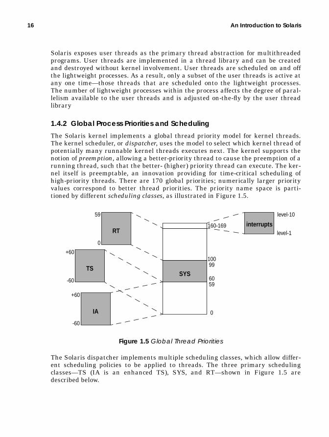
16 An Introduction to Solaris
Solaris exposes user threads as the primary thread abstraction for multithreadedprograms. User threads are implemented in a thread library and can be createdand destroyed without kernel involvement. User threads are scheduled on and offthe lightweight processes. As a result, only a subset of the user threads is active atany one time—those threads that are scheduled onto the lightweight processes.The number of lightweight processes within the process affects the degree of paral-lelism available to the user threads and is adjusted on-the-fly by the user threadlibrary
1.4.2 Global Process Priorities and Scheduling
The Solaris kernel implements a global thread priority model for kernel threads.The kernel scheduler, or dispatcher, uses the model to select which kernel thread ofpotentially many runnable kernel threads executes next. The kernel supports thenotion of preemption, allowing a better-priority thread to cause the preemption of arunning thread, such that the better- (higher) priority thread can execute. The ker-nel itself is preemptable, an innovation providing for time-critical scheduling ofhigh-priority threads. There are 170 global priorities; numerically larger priorityvalues correspond to better thread priorities. The priority name space is parti-tioned by different scheduling classes, as illustrated in Figure 1.5.
The Solaris dispatcher implements multiple scheduling classes, which allow differ-ent scheduling policies to be applied to threads. The three primary schedulingclasses—TS (IA is an enhanced TS), SYS, and RT—shown in Figure 1.5 aredescribed below.
160-169
level-10
level-1
10099
6059
0
TS
+60
-60
IA
+60
-60
RT
59
0
SYS
interrupts
Figure 1.5 Global Thread Priorities

Interprocess Communication 17
• TS — The timeshare scheduling class is the default class for processes andall the kernel threads within the process. It changes process prioritiesdynamically according to recent processor usage in an attempt to evenly allo-cate processor resources among the kernel threads in the system. Process pri-orities and time quantums are calculated according to a timeshare schedulingtable at each clock tick, or during wakeup after sleeping for an I/O. The TSclass uses priority ranges 0 to 59.
• IA — The interactive class is an enhanced TS class used by the desktop win-dowing system to boost priority of threads within the window under focus. IAshares the priority numeric range with the TS class.
• SYS — The system class is used by the kernel for kernel threads. Threads inthe system class are bound threads, that is, there is no time quantum—theyrun until they block. The system class uses priorities 60 to 99.
• RT — The realtime class implements fixed priority, fixed time quantumscheduling. The realtime class uses priorities 100 to 159. Note that threads inthe RT class have a higher priority over kernel threads in the SYS class.
The interrupt priority levels shown in Figure 1.5 are not available for use byanything other than interrupt threads. The intent of their positioning in the prior-ity scheme is to guarantee that interrupts threads have priority over all otherthreads in the system.
1.5 Interprocess Communication
Processes can communicate with each other by using one of several types of inter-process communication (IPC). IPC allows information transfer or synchronizationto occur between processes. Solaris supports four different groups of interprocesscommunication: basic IPC, System V IPC, POSIX IPC, and advanced Solaris IPC.
1.5.1 Traditional UNIX IPC
Solaris implements traditional IPC facilities such as local sockets and pipes. Alocal socket is a network-like connection using the socket(2) system call todirectly connect two processes.
A pipe directly channels data flow from one process to another through an objectthat operates like a file. Data is inserted at one end of the pipe and travels to thereceiving processes in a first-in, first-out order. Data is read and written on a pipewith the standard file I/O system calls. Pipes are created with the pipe(2) sys-tem call or by a special pipe device created in the file system with mknod(1) andthe standard file open(2) system call.

18 An Introduction to Solaris
1.5.2 System V IPC
Three types of IPC originally developed for System V UNIX have become standardacross all UNIX implementations: shared memory, message passing, and sema-phores. These facilities provide the common IPC mechanism used by the majorityof applications today.
• System V Shared Memory — Processes can create a segment of sharedmemory. Changes within the area of shared memory are immediately avail-able to other processes that attach to the same shared memory segment.
• System V Message Queues — A message queue is a list of messages with ahead and a tail. Messages are placed on the tail of the queue and are receivedon the head. Each messages contains a 32-bit type value, followed by a datapayload.
• System V Semaphores — Semaphores are integer-valued objects that sup-port two atomic operations: increment or decrement the value of the integer.Processes can sleep on semaphores that are greater than zero, then can beawakened when the value reaches zero.
1.5.3 POSIX IPC
The POSIX IPC facilities are similar in functionality to System V IPC but areabstracted on top of memory mapped files. The POSIX library routines are calledby a program to create a new semaphore, shared memory segment, or messagequeue using the Solaris file I/O system calls (open (2), read (2), mmap(2), etc.).Internally in the POSIX library, the IPC objects exist as files. The object typeexported to the program through the POSIX interfaces is handled within thelibrary routines.
1.5.4 Advanced Solaris IPC
A new, fast, lightweight mechanism for calling procedures between processes isavailable in Solaris: doors. Doors are a low-latency method of invoking a proce-dure in local process. A door server contains a thread that sleeps, waiting for aninvocation from the door client. A client makes a call to the server through thedoor, along with a small (16 Kbyte) payload. When the call is made from a door cli-ent to a door server, scheduling control is passed directly to the thread in the doorserver. Once a door server has finished handling the request, it passes control andresponse back to the calling thread. The scheduling control allowsultra-low-latency turnaround because the client does not need to wait for theserver thread to be scheduled to complete the request.

Signals 19
1.6 Signals
UNIX systems have provided a process signalling mechanism from the earliestimplementations. The signal facility provides a means to interrupt a process orthread within a process as a result of a specific event. The events that trigger sig-nals can be directly related to the current instruction stream. Such signals,referred to as synchronous signals, originate as hardware trap conditions arisingfrom illegal address references (segmentation violation), illegal math operations(floating point exceptions), and the like.
The system also implements asynchronous signals, which result from an exter-nal event not necessarily related to the current instruction stream. Examples ofasynchronous signals include job control signals and the sending of a signal fromone process or thread to another, for example, sending a kill signal to terminate aprocess.
For each possible signal, a process can establish one of three possible signal dis-positions, which define what action, if any, will be taken when the signal isreceived. Most signals can be ignored, a signal can be caught and a process-spe-cific signal handler invoked, or a process can permit the default action to be taken.Every signal has a predefined default action, for example, terminate the process.Solaris provides a set of programming interfaces that allow signals to be maskedor a specific signal handler to be installed.
The traditional signal model was built on the concept of a process having a sin-gle execution stream at any time. The Solaris kernel’s multithreaded processarchitecture allows for multiple threads of execution within a process, meaningthat a signal can be directed to specific thread. The disposition and handlers forsignals are process-wide; every thread in a multithreaded process has the samesignal disposition and handlers. However, the Solaris model allows for signals to bemasked at the thread level, so different threads within the process can have differ-ent signals masked. (Masking is a means of blocking a signal from being deliv-ered.)
1.7 Memory Management
The Solaris virtual memory (VM) system can be considered to be the core of theoperating system—it manages the system’s memory on behalf of the kernel andprocesses. The main task of the VM system is to manage efficient allocation of thesystem’s physical memory to the processes and kernel subsystems running withinthe operating system. The VM system uses slower storage media (usually disk) tostore data that does not fit within the physical memory of the system, thus accom-modating programs larger than the size of physical memory. The VM system is to

20 An Introduction to Solaris
keeps the most frequently used portions within physical memory and thelesser-used portions on the slower secondary storage.
For processes, the VM system presents a simple linear range of memory, knownas an address space. Each address space is broken into several segments that rep-resent mappings of the executable, heap space (general-purpose, process-allocatedmemory), shared libraries, and a program stack. Each segment is divided intoequal-sized pieces of virtual memory, known as pages, and a hardware memorymanagement unit (MMU) manages the mapping of page-sized pieces of virtualmemory to physical memory. Figure 1.6 shows the relationship between an addressspace, segments, the memory management unit, and physical memory.
The virtual memory system is implemented in a modular fashion. The compo-nents that deal with physical memory management are mostly hardware platformspecific. The platform-dependent portions are implemented in the hardwareaddress translation (HAT) layer.
1.7.1 Global Memory Allocation
The VM system implements demand paging. Pages of memory are allocated ondemand, as they are referenced, and hence portions of an executable or sharedlibrary are allocated on demand. Loading pages of memory on demand dramati-cally lowers the memory footprint and startup time of a process. When an area of
V P
0000
ProcessBinary
ProcessScratchMemory
Process’sLinear VirtualAddress Space
VirtualMemorySegments Virtual
Memory
MMU
Virtual-to-PhysicalTranslationTables
PhysicalMemory
(Heap)
PhysicalMemoryPagesPage-sized
Pieces of
Figure 1.6 Address Spaces, Segments, and Pages

Files and File Systems 21
virtual memory is accessed, the hardware MMU raises an event to tell the kernelthat an access has occurred to an area of memory that does not have physicalmemory mapped to it. This event is a page fault. The heap of a process is also allo-cated in a similar way: initially, only virtual memory space is allocated to the pro-cess. When memory is first referenced, a page fault occurs and memory is allocatedone page at a time.
The virtual memory system uses a global paging model that implements a sin-gle global policy to manage the allocation of memory between processes. A scan-ning algorithm calculates the least used portion of the physical memory. A kernelthread (the page scanner) scans memory in physical page order when the amountof free memory falls below a preconfigured threshold. Pages that have not beenused recently are stolen and placed onto a free list for use by other processes.
1.7.2 Kernel Memory Management
The Solaris kernel requires memory for kernel instructions, data structures, andcaches. Most of the kernel’s memory is not pageable, that is, it is allocated fromphysical memory which cannot be stolen by the page scanner. This characteristicavoids deadlocks that could occur within the kernel if a kernel memory manage-ment function caused a page fault while holding a lock for another criticalresource. The kernel cannot rely on the global paging used by processes, so itimplements its own memory allocation systems.
A core kernel memory allocator—the slab allocator—allocates memory for ker-nel data structures. As the name suggests, the allocator subdivides large contigu-ous areas of memory (slabs) into smaller chunks for data structures. Allocationpools are organized so that like-sized objects are allocated from the same continu-ous segments, thereby dramatically reducing fragmentation that could result fromcontinuous allocation and deallocation.
1.8 Files and File Systems
Solaris provides facilities for storage and management of data, as illustrated inFigure 1.7. A file provides a container for data, a directory contains a number of
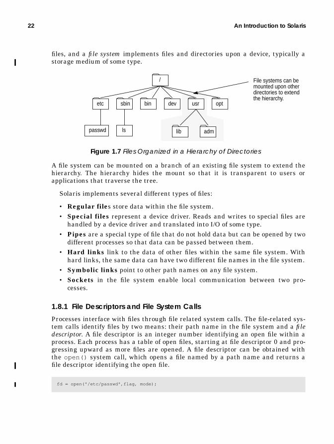
22 An Introduction to Solaris
files, and a file system implements files and directories upon a device, typically astorage medium of some type.
A file system can be mounted on a branch of an existing file system to extend thehierarchy. The hierarchy hides the mount so that it is transparent to users orapplications that traverse the tree.
Solaris implements several different types of files:
• Regular files store data within the file system.• Special files represent a device driver. Reads and writes to special files are
handled by a device driver and translated into I/O of some type.• Pipes are a special type of file that do not hold data but can be opened by two
different processes so that data can be passed between them.• Hard links link to the data of other files within the same file system. With
hard links, the same data can have two different file names in the file system.• Symbolic links point to other path names on any file system.• Sockets in the file system enable local communication between two pro-
cesses.
1.8.1 File Descriptors and File System Calls
Processes interface with files through file related system calls. The file-related sys-tem calls identify files by two means: their path name in the file system and a filedescriptor. A file descriptor is an integer number identifying an open file within aprocess. Each process has a table of open files, starting at file descriptor 0 and pro-gressing upward as more files are opened. A file descriptor can be obtained withthe open() system call, which opens a file named by a path name and returns afile descriptor identifying the open file.
fd = open("/etc/passwd",flag, mode);
etc sbin bin dev usr
/
opt
passwd ls lib adm
Figure 1.7 Files Organized in a Hierarchy of Directories
File systems can bemounted upon otherdirectories to extendthe hierarchy.

Files and File Systems 23
Once a file has been opened, a file descriptor can be used for operations on the file.The read (2) and write (2) operations provide basic file I/O, along with severalother advanced mechanisms for performing more complex operations. A filedescriptor is eventually closed by the close (2) system call or by the process’s exit.By default, file descriptors 0, 1, and 2 are opened automatically by the C runtimelibrary and represent the standard input, standard output, and standard errorstreams for a process.
1.8.2 The Virtual File System Framework
Solaris provides a framework under which multiple file system types are imple-mented: the virtual file system framework. Earlier implementations of UNIX useda single file system type for all of the mounted file systems; typically, the UFS filesystem from BSD UNIX. The virtual file system framework, developed to enablethe network file system (NFS) to coexist with the UFS file system in SunOS 2.0,became a standard part of System V in SVR4 and Solaris.
Each file system provides file abstractions in the standard hierarchical manner,providing standard file access interfaces even if the underlying file system imple-mentation varies. The file system framework allows almost any objects to beabstracted as files and file systems. Some file systems store file data on stor-age-based media, whereas other implementations abstract objects other than stor-age as files. For example, the procfs file system abstracts the process tree, whereeach file in the file system represents a process in the process tree. We can catego-rize Solaris file systems into the following groups:
• Storage Based — Regular file systems that provide facilities for persistentstorage and management of data. The Solaris UFS and PC/DOS file systemsare examples.
• Network File Systems — File systems that provide files which appear to bein a local directory structure but are stored on a remote network server; forexample, Sun’s network file system (NFS).
• Pseudo File Systems — File systems that present various abstractions asfiles in a file system. The /proc pseudo file system represents the addressspace of a process as a series of files.
The framework provides a single set of well-defined interfaces that are file systemindependent; the implementation details of each file system are hidden behindthese interfaces. Two key objects represent these interfaces: the virtual file, orvnode, and the virtual file system, or vfs objects. The vnode interfaces implementfile-related functions, and the vfs interfaces implement file system managementfunctions. The vnode and vfs interfaces call appropriate file system functionsdepending on the type of file system being operated on. Figure 1.8 shows the filesystem layers. File-related functions are initiated through a system call or from

24 An Introduction to Solaris
another kernel subsystem and are directed to the appropriate file system via thevnode/vfs layer.
Table 1-2 summarizes the major file system types that are implemented in Solaris.
Table 1-2 File Systems Available in Solaris File System Framework
FileSystem
Type Device Description
ufs Regular Disk UNIX Fast File system, default inSolaris
pcfs Regular Disk MS-DOS file systemhsfs Regular Disk High Sierra file system (CD-ROM)tmpfs Regular Memory Uses memory and swapnfs Pseudo Network Network file systemcachefs Pseudo File system Uses a local disk as cache for another
NFS file systemautofs Pseudo File system Uses a dynamic layout to mount
other file systemsspecfs Pseudo Device Drivers File system for the /dev devices
System Call Interface
VFS: File-System-Independent Layer (VFS & VNODE INTERFACES)
UFS PCFS HSFS VxFS NFS PROCFS
rea
d()
write
()
op
en
()
clo
se()
mkd
ir()
rmd
ir()
ren
am
e()
link(
)
un
link(
)
see
k()
fsyn
c()
ioct
l()
cre
at(
)
mo
un
t()
um
ou
nt(
)
sta
tfs(
)
syn
c()
VNODE OPERATIONS VFS OPERATIONS
QFS
Figure 1.8 VFS/Vnode Architecture

I/O Architecture 25
1.9 I/O Architecture
Traditional UNIX implements kernel-resident device drivers to interface withhardware devices. The device driver manages data transfer and register I/O andhandles device hardware interrupts. A device driver typically has to know inti-mate details about the hardware device and the layout of buses to which the deviceis connected. Solaris extends traditional device driver management functions byusing separate drivers for devices and buses: a device driver controls a device’shardware, and a bus nexus driver controls and translates data between two differ-ent types of buses.
Solaris organizes I/O devices in a hierarchy of bus nexus and instances ofdevices, according to the physical connection hierarchy of the devices. The hierar-chy shown in Figure 1.9 represents a typical Solaris device tree.
procfs Pseudo Kernel /proc file system representing pro-cesses
sockfs Pseudo Network File system of socket connectionsfdfs Pseudo File Descriptors Allows a process to see its open files
in /dev/fdfifofs Pseudo Files FIFO file system
Table 1-2 File Systems Available in Solaris File System Framework (Continued)
FileSystem
Type Device Description
rootnexus node
pcinexus node
eisanexus node
pcmcianexus node
scsi ctlrnexus node
sd 0device node
sd 0device node
ethernet ctlrdevice node
Figure 1.9 The Solaris Device Tree
PCI Busserial modem
device node
System Bus
SCSI Bus
SCSI Device Driver (sd)
SCSI Host AdapterNexus Driver

26 An Introduction to Solaris
Each bus connects to another bus though a bus nexus. In our example, nexusdrivers are represented by the PCI, EISA, PCMCIA, and SCSI nodes. The SCSIhost adapter is a bus nexus bridging the PCI and SCSI bus it controls, underneathwhich the SCSI disk (sd ) device driver implements device nodes for each disk onthe SCSI chain.
The Solaris device driver interface (DDI) hides the implementation specifics ofthe platform and bus hierarchy from the device drivers. The DDI provides inter-faces for registering interrupts, mapping registers, and accessing DMA memory. Inthat way, the kernel can interface with the device.
Device drivers are implemented as loadable modules, that is, as separate bina-ries containing driver code. Device drivers are loaded automatically the first timetheir device is accessed.

2
KERNEL SERVICES
The Solaris kernel manages operating system resources and provides facilitiesto user processes. In this chapter we explore how the kernel implements these ser-vices. We begin by discussing the boundary between user programs and kernelmode, then discuss the mechanisms used to switch between user and kernel mode,including system calls, traps, and interrupts.
2.1 Access to Kernel Services
The Solaris kernel insulates processes from kernel data structures and hardwareby using two distinct processor execution modes: nonprivileged mode and privi-leged mode. Privileged mode is often referred to as kernel mode; nonprivilegedmode is referred to as user mode.
In nonprivileged mode, a process can access only its own memory, whereas inprivileged mode, access is available to all of the kernel’s data structures and theunderlying hardware. The kernel executes processes in nonprivileged mode to pre-vent user processes from accessing data structures or hardware registers that mayaffect other processes or the operating environment. Because only Solaris kernelinstructions can execute in privileged mode, the kernel can mediate access to ker-nel data structures and hardware devices.
27
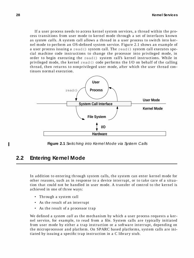
28 Kernel Services
If a user process needs to access kernel system services, a thread within the pro-cess transitions from user mode to kernel mode through a set of interfaces knownas system calls. A system call allows a thread in a user process to switch into ker-nel mode to perform an OS-defined system service. Figure 2.1 shows an example ofa user process issuing a read() system call. The read() system call executes spe-cial machine code instructions to change the processor into privileged mode, inorder to begin executing the read() system call’s kernel instructions. While inprivileged mode, the kernel read() code performs the I/O on behalf of the callingthread, then returns to nonprivileged user mode, after which the user thread con-tinues normal execution.
Figure 2.1 Switching into Kernel Mode via System Calls
2.2 Entering Kernel Mode
In addition to entering through system calls, the system can enter kernel mode forother reasons, such as in response to a device interrupt, or to take care of a situa-tion that could not be handled in user mode. A transfer of control to the kernel isachieved in one of three ways:
• Through a system call• As the result of an interrupt• As the result of a processor trap
We defined a system call as the mechanism by which a user process requests a ker-nel service, for example, to read from a file. System calls are typically initiatedfrom user mode by either a trap instruction or a software interrupt, depending onthe microprocessor and platform. On SPARC based platforms, system calls are ini-tiated by issuing a specific trap instruction in a C library stub.
User Mode
Kernel Mode
User
Process
System Call Interface
File System
read()
I/O
Hardware

Entering Kernel Mode 29
An interrupt is a vectored transfer of control into the kernel, typically initiatedby a hardware device, for example, a disk controller signalling the completion of anI/O. Interrupts can also be initiated from software. Hardware interrupts typicallyoccur asynchronously to the currently executing thread, and they occur in inter-rupt context.
A trap is also a vectored transfer of control into the kernel, initiated by the pro-cessor. The primary distinction between traps and interrupts is this: Traps typi-cally occur as a result of the current executing thread, for example, adivide-by-zero error or a memory page fault; interrupts are asynchronous events,that is, the source of the interrupt is something unrelated to the currently execut-ing thread. On SPARC processors, the distinction is somewhat blurred, since atrap is also the mechanism used to initiate interrupt handlers.
2.2.1 Context
A context describes the environment for a thread of execution. We often refer totwo distinct types of context: an execution context (thread stacks, open file lists,resource accounting, etc.) and a virtual memory context (the virtual-to-physicaladdress mappings).
2.2.1.1 Execution Context
Threads in the kernel can execute in process, interrupt, or kernel context.
• Process Context — In the process context, the kernel thread acts on behalfof the user process and has access to the process’s user area (uarea), and pro-cess structures for resource accounting. The uarea (struct u ) is a specialarea within the process that contains process information of interest to thekernel: typically, the process’s open file list, process identification informa-tion, etc. For example, when a process executes a system call, a thread withinthe process transitions into kernel mode and then has access to the uarea ofthe process’s data structures, so that it can pass arguments, update systemtime usage, etc.
• Interrupt Context — Interrupt threads execute in an interrupt context.They do not have access to the data structures of the process or thread theyinterrupted. Interrupts have their own stack and can access only kernel datastructures.
• Kernel Context — Kernel management threads run in the kernel context.In kernel context, system management threads share the kernel’s environ-ment with each other. Kernel management threads typically cannot accessprocess-related data. Examples of kernel management threads are the pagescanner and the NFS server.
2.2.1.2 Virtual Memory Context
A virtual memory context is the set of virtual-to-physical address translations thatconstruct a memory environment. Each process has its own virtual memory con-
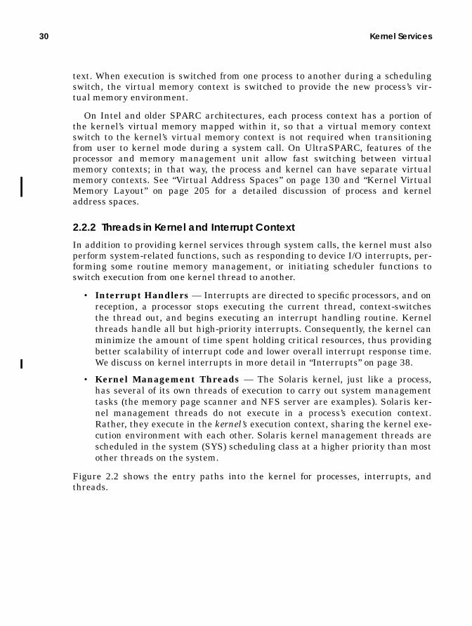
30 Kernel Services
text. When execution is switched from one process to another during a schedulingswitch, the virtual memory context is switched to provide the new process’s vir-tual memory environment.
On Intel and older SPARC architectures, each process context has a portion ofthe kernel’s virtual memory mapped within it, so that a virtual memory contextswitch to the kernel’s virtual memory context is not required when transitioningfrom user to kernel mode during a system call. On UltraSPARC, features of theprocessor and memory management unit allow fast switching between virtualmemory contexts; in that way, the process and kernel can have separate virtualmemory contexts. See “Virtual Address Spaces” on page 130 and “Kernel VirtualMemory Layout” on page 205 for a detailed discussion of process and kerneladdress spaces.
2.2.2 Threads in Kernel and Interrupt Context
In addition to providing kernel services through system calls, the kernel must alsoperform system-related functions, such as responding to device I/O interrupts, per-forming some routine memory management, or initiating scheduler functions toswitch execution from one kernel thread to another.
• Interrupt Handlers — Interrupts are directed to specific processors, and onreception, a processor stops executing the current thread, context-switchesthe thread out, and begins executing an interrupt handling routine. Kernelthreads handle all but high-priority interrupts. Consequently, the kernel canminimize the amount of time spent holding critical resources, thus providingbetter scalability of interrupt code and lower overall interrupt response time.We discuss on kernel interrupts in more detail in “Interrupts” on page 38.
• Kernel Management Threads — The Solaris kernel, just like a process,has several of its own threads of execution to carry out system managementtasks (the memory page scanner and NFS server are examples). Solaris ker-nel management threads do not execute in a process’s execution context.Rather, they execute in the kernel’s execution context, sharing the kernel exe-cution environment with each other. Solaris kernel management threads arescheduled in the system (SYS) scheduling class at a higher priority than mostother threads on the system.
Figure 2.2 shows the entry paths into the kernel for processes, interrupts, andthreads.

Entering Kernel Mode 31
Figure 2.2 Process, Interrupt, and Kernel Threads
2.2.3 UltraSPARC I & II Traps
The SPARC processor architecture uses traps as a unified mechanism to handlesystem calls, processor exceptions, and interrupts. A SPARC trap is a procedurecall initiated by the microprocessor as a result of a synchronous processor excep-tion, an asynchronous processor exception, a software-initiated trap instruction, ora device interrupt.
Upon receipt of a trap, the UltraSPARC I & II processor enters privileged modeand transfers control to the instructions, starting at a predetermined location in atrap table. The trap handler for the type of trap received is executed, and once theinterrupt handler has finished, control is returned to the interrupted thread. Atrap causes the hardware to do the following:
• Save certain processor state (program counters, condition code registers, traptype etc.)
• Enter privileged execution mode• Begin executing code in the corresponding trap table slot
When an UltraSPARC trap handler processing is complete, it issues a SPARC DONEor RETRY instruction to return to the interrupted thread.
User Mode
Kernel Mode
User
Process
System Call Interface
InterruptThread
Virtual
ManagerMemory
Interrupt
KernelThreads
Interrupts are light-weight and do mostof their work byscheduling an inter-rupt thread.
SystemCall
Hardware

32 Kernel Services
The UltraSPARC I & II trap table is an in-memory table that contains the firsteight instructions for each type of trap. The trap table is located in memory at theaddress stored in the trap table base address register (TBA), which is initializedduring boot. Solaris places the trap table at the base of the kernel (known as ker-nelbase ) in a locked-down (non-pageable) 4-Mbyte page so that no mem-ory-related traps (page faults or TLB misses) will occur during execution ofinstructions in the trap table. (For a detailed kernel memory map, see Appendix B,“Kernel Virtual Address Maps”.")
2.2.3.1 UltraSPARC I & II Trap Types
The trap table contains one entry for each type of trap and provides a specific han-dler for each trap type. The UltraSPARC I & II traps can be categorized into thefollowing broad types:
• Processor resets — Power-on reset, machine resets, software-initiatedresets
• Memory management exceptions — MMU page faults, page protectionviolations, memory errors, misaligned accesses, etc.
• Instruction exceptions — Attempts to execute privileged instructions fromnonprivileged mode, illegal instructions, etc.
• Floating-point exceptions — Floating-point exceptions, floating-pointmode instruction attempted when floating point unit disabled, etc.
• SPARC register management — Traps for SPARC register window spill-ing, filling, or cleaning.
• Software-initiated traps — Traps initiated by the SPARC trap instruction(Tcc); primarily used for system call entry in Solaris.
Table 2-1 shows the UltraSPARC I & II trap types, as implemented in Solaris.
Table 2-1 Solaris UltraSPARC I & II Traps
Trap Definition Trap Type PriorityPower-on reset 001 0Watchdog reset 002 1Externally initiated reset 003 1Software-initiated reset 004 1RED state exception 005 1Reserved 006...007 n/aInstruction access exception 008 5Instruction access MMU miss 009 2Instruction access error 00A 3Reserved 00B…00F n/aIllegal instruction 010 7

Entering Kernel Mode 33
2.2.3.2 UltraSPARC I & II Trap Priority Levels
Each UltraSPARC I & II trap has an associated priority level. The processor’s traphardware uses the level to decide which trap takes precedence when more thanone trap occurs on a processor at a given time. When two or more traps are pend-ing, the highest-priority trap is taken first (0 is the highest priority).
Interrupt traps are subject to trap priority precedence. In addition, interrupttraps are compared against the processor interrupt level (PIL). The UltraSPARC I& II processor will only take an interrupt trap that has an interrupt request level
Attempt to execute privileged instruction 011 6Unimplemented load instruction 012 6Unimplmeneted store instruction 013 6Reserved 014…01F n/aFloating-point unit disabled 020 8Floating-point exception ieee754 021 11Floating-point exception – other 022 11Tag overflow 023 14SPARC register window clean 024…027 10Division by zero 028 15Internal processor error 029 4Data access exception 030 12Data access MMU miss 031 12Data access error 032 12Data access protection 033 12Memory address not aligned 034 10Load double memory address not aligned 035 10Store double memory address not aligned 036 10Privileged action 037 11Load quad memory address not aligned 038 10Store quad memory address not aligned 039 10Reserved 03A…03F n/aAsynchronous data error 040 2Interrupt level n, where n=1...15 041…04F 32-nReserved 050…05F n/aVectored interrupts 060…07F Int. SpecificSPARC register window overflows 080…0BF 9SPARC register window underflows 0C0…0FF 9Trap instructions Tcc 100…17F 16Reserved 180…1FF n/a
Table 2-1 Solaris UltraSPARC I & II Traps (Continued)
Trap Definition Trap Type Priority

34 Kernel Services
greater than that stored in the processor’s PIL register. We discuss this behavior inmore detail in “Interrupts” on page 38.
2.2.3.3 UltraSPARC I & II Trap Levels
The UltraSPARC I & II processor introduced nested traps, that is, a trap can bereceived while another trap is being handled. Prior SPARC implementations couldnot handle nested traps (a “watchdog reset” occurs on pre-UltraSPARC processorsif a trap occurs while the processor is executing a trap handler). Also introducedwas the notion of trap levels to describe the level of trap nesting. The nested trapshave five levels, starting at trap level 0 (normal execution, no trap) through traplevel 4 (trap level 4 is actually an error handling state and should not be reachedduring normal processing).
When an UltraSPARC I & II trap occurs, the CPU increments the trap level(TL). The most recent processor state is saved on the trap stack, and the trap han-dler is entered. On exit from the handler, the trap level is decremented.
UltraSPARC I & II also implements an alternate set of global registers for eachtrap level. Those registers remove most of the overhead associated with savingstate, making it very efficient to move between trap levels.
2.2.3.4 UltraSPARC I & II Trap Table Layout
The UltraSPARC I & II trap table is halved: the lower half contains trap handlersfor traps taken at trap level 0, and the upper half contains handlers for trapstaken when the trap level is 1 or greater. We implement separate trap handlers fortraps taken at trap level greater than zero (i.e., we are already handling a trap)because not all facilities are available when a trap is taken within a trap.
For example, if a trap handler at trap level 0 takes a memory-related trap (suchas a translation miss), the trap handler can assume a higher-level trap handlerwill take care of the trap; but a higher-level trap handler cannot always make thesame assumption. Each half of the trap table contains 512 trap handler slots, onefor each trap type shown in Table 2-1.
Each half of the trap table is further divided into two sections, each of whichcontains 256 hardware traps in the lower section, followed by 256 software traps inthe upper section (for the SPARC Tcc software trap instructions). Upon receipt ofa trap, the UltraSPARC I & II processor jumps to the instructions located in thetrap table at the trap table base address (set in the TBA register) plus the offset ofthe trap level and trap type. There are 8 instructions (32 bytes) at each slot in thetable; hence, the trap handler address is calculated as follows:
TL = 0: trap handler address = TBA + (trap type x 32)
TL > 0: trap handler address = TBA + 512 + (trap type x 32)
As a side note, space is reserved in the trap table so that trap handlers for SPARCregister clean, spill, and fill (register window operations) can actually be longer

Entering Kernel Mode 35
than 8 instructions. This allows branchless inline handlers to be implemented suchthat the entire handler fits within the trap table slot.
Figure 2.3 shows the UltraSPARC I & II trap table layout.
Figure 2.3 UltraSPARC I & II Trap Table Layout
2.2.3.5 Software TrapsSoftware traps are initiated by the SPARC trap instruction, Tcc . The opcode forthe trap instruction includes a 6-bit software trap number, which indexes into thesoftware portion of the trap table. Software traps are used primarily for systemcalls in the Solaris kernel.
There are three software traps for system calls: one for native system calls, onefor 32-bit system calls (when 32-bit applications are run on a 64-bit kernel), andone for SunOS 4.x binary compatibility system calls. System calls vector through acommon trap by setting the system call number in a global register and then issu-ing a trap instruction. We discuss regular systems calls in more detail in “SystemCalls” on page 44.
There are also several ultra-fast system calls implemented as their own trap.These system calls pass their simple arguments back and forth via registers.Because the system calls don’t pass arguments on the stack, much less of the pro-cess state needs to be saved during transition into kernel mode, resulting in amuch faster system call implementation. The fast system calls (e.g.,get_hrestime ) are time-related calls.
Table 2-2 lists UltraSPARC software traps, including ultra-fast system calls.
Hardware Traps
Spill/Fill Traps
Software Traps
Reserved
Hardware Traps
Spill/Fill Traps
Software Traps
Reserved
Trap Level = 0
Trap Level > 0
Trap Table Contents Trap Types
000...07F
080...0FF
100...17F
180...1FF
000...07F
080...0FF
100...17F
180...1FF

36 Kernel Services
2.2.3.6 A Utility for Trap Analysis
An unbundled tool, trapstat , dynamically monitors trap activity. The tool moni-tors counts of each type of trap for each processor in the system during an intervalspecified as the argument. It is currently implemented on UltraSPARC and Intelx86 processor architectures, on Solaris 7 and later releases.
You can download trapstat from the website for this book:http://www.solarisinternals.com . Simply untar the archive and install thedriver with the add_drv command.
Note: trapstat is not supported by Sun. Do not use it on production machinesbecause it dynamically loads code into the kernel.
Table 2-2 UltraSPARC Software Traps
Trap Definition Trap TypeValue
Priority
Trap instruction (SunOS 4.x syscalls) 100 16Trap instruction (user breakpoints) 101 16Trap instruction (divide by zero) 102 16Trap instruction (flush windows) 103 16Trap instruction (clean windows) 104 16Trap instruction (do unaligned references) 106 16Trap instruction (32-bit system call) 108 16Trap instruction (set trap0) 109 16Trap instructions (user traps) 110 – 123 16Trap instructions (get_hrtime ) 124 16Trap instructions (get_hrvtime ) 125 16Trap instructions (self_xcall ) 126 16Trap instructions (get_hrestime ) 127 16Trap instructions (trace) 130-137 16Trap instructions (64-bit system call) 140 16
# tar xvf trapstat28.tar-r-xr-xr-x 0/2 5268 Jan 31 03:57 2000 /usr/bin/trapstat-rwxrwxr-x 0/1 33452 Feb 10 23:17 2000 /usr/bin/sparcv7/trapstat-rwxrwxr-x 0/1 40432 Feb 10 23:16 2000 /usr/bin/sparcv9/trapstat-rw-rw-r-- 0/1 21224 Sep 8 17:28 1999 /usr/kernel/drv/trapstat-rw-r--r-- 0/1 188 Aug 31 10:06 1999 /usr/kernel/drv/trapstat.conf-rw-rw-r-- 0/1 37328 Sep 8 17:28 1999 /usr/kernel/drv/sparcv9/trapstat# add_drv trapstat

Entering Kernel Mode 37
Once trapstat is installed, use it to analyze the traps taken on each processorinstalled in the system.
The example above shows the traps taken on a two-processor Ultra-SPARC-II-based system. The first column shows the trap type, followed by anASCII description of the trap type. The remaining columns are the trap counts foreach processor.
We can see that most trap activities in the SPARC are register clean, spill, andfill traps—they perform SPARC register window management. The level-1 throughlevel 14 and int-vec rows are the interrupt traps. The iltb-miss, dtlb-miss, anddtlb-prot rows are the UltraSPARC memory management traps, which occur eachtime a TLB miss or protection fault occurs. (More on UltraSPARC memory man-agement in “The UltraSPARC-I and -II HAT” on page 193). At the bottom of theoutput we can see the system call trap for 32-bit systems calls and two specialultra-fast system calls (getts and gethrtime ), which each use their own trap.
The SPARC V9 Architecture Manual [30] provides a full reference for the imple-mentation of UltraSPARC traps. We highly recommend this text for specific imple-mentation details on the SPARC V9 processor architecture.
# trapstat 3vct name | cpu0 cpu1---------------------+-------------- 24 cleanwin | 3636 4285 41 level-1 | 99 1 45 level-5 | 1 0 46 level-6 | 60 0 47 level-7 | 23 0 4a level-10 | 100 0 4d level-13 | 31 67 4e level-14 | 100 0 60 int-vec | 161 90 64 itlb-miss | 5329 11128 68 dtlb-miss | 39130 82077 6c dtlb-prot | 3 2 84 spill-1-normal | 1210 992 8c spill-3-normal | 136 286 98 spill-6-normal | 5752 20286 a4 spill-1-other | 476 1116 ac spill-3-other | 4782 9010 c4 fill-1-normal | 1218 752 cc fill-3-normal | 3725 7972 d8 fill-6-normal | 5576 20273103 flush-wins | 31 0108 syscall-32 | 2809 3813124 getts | 1009 2523127 gethrtime | 1004 477---------------------+--------------ttl | 76401 165150

38 Kernel Services
2.3 Interrupts
An interrupt is the mechanism that a device uses to signal the kernel that it needsattention and some immediate processing is required on behalf of that device.Solaris services interrupts by context-switching out the current thread running ona processor and executing an interrupt handler for the interrupting device. Forexample, when a packet is received on a network interface, the network controllerinitiates an interrupt to begin processing the packet.
2.3.1 Interrupt Priorities
Solaris assigns priorities to interrupts to allow overlapping interrupts to be han-dled with the correct precedence; for example, a network interrupt can be config-ured to have a higher priority than a disk interrupt.
The kernel implements 15 interrupt priority levels: level 1 through level 15,where level 15 is the highest priority level. On each processor, the kernel can maskinterrupts below a given priority level by setting the processor’s interrupt level.Setting the interrupt level blocks all interrupts at the specified level and lower.That way, when the processor is executing a level 9 interrupt handler, it does notreceive interrupts at level 9 or below; it handles only higher-priority interrupts.
Interrupts that occur with a priority level at or lower than the processor’s inter-rupt level are temporarily ignored. An interrupt will not be acknowledged by a pro-cessor until the processor’s interrupt level is less than the level of the pending
151413121110987654321Low Interrupt Priority Level
High Interrupt Priority Level
Clock Interrupt
Network Interrupts
Disk Interrupts
PIO Serial Interrupts
Interrupts at level10 or below arehandled by interruptthreads. Clockinterrupts are handledby a specific clockinterrupt handlerkernel thread. Thereis one clock interruptthread systemwide.
Figure 2.4 Solaris Interrupt Priority Levels

Interrupts 39
interrupt. More important interrupts have a higher priority level to give them abetter chance to be serviced than lower priority interrupts.
Figure 2.4 illustrates interrupt priority levels.
2.3.1.1 Interrupts as Threads
Interrupt priority levels can be used to synchronize access to critical sections usedby interrupt handlers. By raising the interrupt level, a handler can ensure exclu-sive access to data structures for the specific processor that has elevated its prior-ity level. This is in fact what early, uniprocessor implementations of UNIX systemsdid for synchronization purposes.
But masking out interrupts to ensure exclusive access is expensive; it blocksother interrupt handlers from running for a potentially long time, which could leadto data loss if interrupts are lost because of overrun. (An overrun condition is onein which the volume of interrupts awaiting service exceeds the system’s ability toqueue the interrupts.) In addition, interrupt handlers using priority levels alonecannot block, since a deadlock could occur if they are waiting on a resource held bya lower-priority interrupt.
For these reasons, the Solaris kernel implements most interrupts as asynchro-nously created and dispatched high-priority threads. This implementation allowsthe kernel to overcome the scaling limitations imposed by interrupt blocking forsynchronizing data access and thus provides low-latency interrupt response times.
Interrupts at priority 10 and below are handled by Solaris threads. These inter-rupt handlers can then block if necessary, using regular synchronization primi-tives such as mutex locks. Interrupts, however, must be efficient, and it is tooexpensive to create a new thread each time an interrupt is received. For this rea-son, each processor maintains a pool of partially initialized interrupt threads, onefor each of the lower 9 priority levels plus a systemwide thread for the clock inter-rupt. When an interrupt is taken, the interrupt uses the interrupt thread’s stack,and only if it blocks on a synchronization object is the thread completely initial-

40 Kernel Services
ized. This approach, exemplified in Figure 2.5, allows simple, fast allocation ofthreads at the time of interrupt dispatch.
Figure 2.5 Handling Interrupts with Threads
Figure 2.5 depicts a typical scenario when an interrupt with priority 9 or lessoccurs (level 10 clock interrupts are handled slightly differently). When an inter-rupt occurs, the interrupt level is raised to the level of the interrupt to block subse-quent interrupts at this level (and lower levels). The currently executing thread isinterrupted and pinned to the processor. A thread for the priority level of the inter-rupt is taken from the pool of interrupt threads for the processor and is con-text-switched in to handle the interrupt.
The term pinned refers to a mechanism employed by the kernel that avoids con-text switching out the interrupted thread. The executing thread is pinned underthe interrupt thread. The interrupt thread “borrows” the LWP from the executingthread. While the interrupt handler is running, the interrupted thread is pinned toavoid the overhead of having to completely save its context; it cannot run on anyprocessor until the interrupt handler completes or blocks on a synchronizationobject. Once the handler is complete, the original thread is unpinned and resched-uled.
If the interrupt handler thread blocks on a synchronization object (e.g., a mutexor condition variable) while handling the interrupt, it is converted into a completekernel thread capable of being scheduled. Control is passed back to the inter-rupted thread, and the interrupt thread remains blocked on the synchronizationobject. When the synchronization object is unblocked, the thread becomes runna-ble and may preempt lower-priority threads to be rescheduled.
The processor interrupt level remains at the level of the interrupt, blockinglower-priority interrupts, even while the interrupt handler thread is blocked. Thisprevents lower-priority interrupt threads from interrupting the processing ofhigher-level interrupts. While interrupt threads are blocked, they are pinned to
CPUInterruptThreads
Executing Thread1
2Thread is interrupted.
Interrupt thread fromCPU thread pool for thepriority of the interrupt
3
Thread is resumed.
4
987654321
handles the interrupt.

Interrupts 41
the processor they initiated on, guaranteeing that each processor will always havean interrupt thread available for incoming interrupts.
Level 10 clock interrupts are handled in a similar way, but since there is onlyone source of clock interrupt, there is a single, systemwide clock thread. Clockinterrupts are discussed further in “The System Clock” on page 54.
2.3.1.2 Interrupt Thread Priorities
Interrupts that are scheduled as threads share global dispatcher priorities withother threads. See Chapter 9, “The Solaris Kernel Dispatcher”” for a full descrip-tion of the Solaris dispatcher. Interrupt threads use the top ten global dispatcherpriorities, 160 to 169. Figure 2.6 shows the relationship of the interrupt dis-patcher priorities with the real-time, system (kernel) threads and the timeshareand interactive class threads.
Figure 2.6 Interrupt Thread Global Priorities
2.3.1.3 High-Priority Interrupts
Interrupts above priority 10 block out all lower-priority interrupts until they com-plete. For this reason, high-priority interrupts need to have an extremely shortcode path to prevent them from affecting the latency of other interrupt handlersand the performance and scalability of the system. High-priority interrupt threadsalso cannot block; they can use only the spin variety of synchronization objects.This is due to the priority level the dispatcher uses for synchronization. The dis-patcher runs at level 10, thus code running at higher interrupt levels can not enterthe dispatcher. High-priority threads typically service the minimal requirements ofthe hardware device (the source of the interrupt), then post down a lower-prioritysoftware interrupt to complete the required processing.
160-169
level 10
level 1
10099
6059
0
TS
+60
-60
IA
+60
-60
RT
59
0
SYS
interrupts

42 Kernel Services
2.3.1.4 UltraSPARC Interrupts
On UltraSPARC systems (sun4u), the intr_vector[] array is a single, system-wide interrupt table for all hardware and software interrupts, as shown in Figure2.7.
Figure 2.7 Interrupt Table on sun4u Architectures
Interrupts are added to the array through an add_ivintr() function. (Otherplatforms have a similar function for registering interrupts.) Each interrupt regis-tered with the kernel has a unique interrupt number that locates the handlerinformation in the interrupt table when the interrupt is delivered. The interruptnumber is passed as an argument to add_ivintr() , along with a function pointer(the interrupt handler, iv_handler ), an argument list for the handler (iv_arg ),and the priority level of the interrupt (iv_pil ).
Solaris 2.5.1 and Solaris 2.6 allow for unsafe device drivers—drivers that havenot been made multiprocessor safe through the use of locking primitives. Forunsafe drivers, a mutex lock locks the interrupt entry to prevent multiple threadsfrom entering the driver’s interrupt handler.
Solaris 7 requires that all drivers be minimally MP safe, dropping the require-ment for a lock on the interrupt table entry. The iv_pending field is used as partof the queueing process; generated interrupts are placed on a per-processor list ofinterrupts waiting to be processed. The pending field is set until a processor pre-pares to field the interrupt, at which point the pending field is cleared.
A kernel add_softintr() function adds software-generated interrupts to thetable. The process is the same for both functions: use the interrupt number passedas an argument as an index to the intr_vector[] array, and add the entry. Thesize of the array is large enough that running out of array slots is unlikely.
2.3.2 Interrupt Monitoring
You can use the mpstat (1M) and vmstat (1M) commands to monitor interruptactivity on a Solaris system. mpstat (1M) provides interrupts-per-second for each
intr_vectoriv_handleriv_argiv_piliv_pendingiv_mutex
Solaris 2.5.1& 2.6 only
intr_vector

Interrupts 43
CPU in the intr column, and interrupts handled on an interrupt thread (low-levelinterrupts) in the ithr column.
2.3.3 Interprocessor Interrupts and Cross-Calls
The kernel can send an interrupt or trap to another processor when it requiresanother processor to do some immediate work on its behalf. Interprocessor inter-rupts are delivered through the poke_cpu() function; they are used for the fol-lowing purposes:
• Preempting the dispatcher — A thread may need to signal a thread run-ning on another processor to enter kernel mode when a preemption isrequired (initiated by a clock or timer event) or when a synchronization objectis released. Chapter 9, “The Dispatcher” further discusses preemption.
• Delivering a signal — The delivery of a signal may require interrupting athread on another processor.
• Starting/stopping /proc threads — The /proc infrastructure uses inter-processor interrupts to start and stop threads on different processors.
Using a similar mechanism, the kernel can also instruct a processor to execute aspecific low-level function by issuing a processor-to-processor cross-call. Cross-callsare typically part of the processor-dependent implementation. UltraSPARC ker-nels use cross-calls for two purposes:
• Implementing interprocessor interrupts — As discussed above.• Maintaining virtual memory translation consistency — Implementing
cache consistency on SMP platforms requires the translation entries to beremoved from the MMU of each CPU that a thread has run on when a vir-tual address is unmapped. On UltraSPARC, user processes issuing an unmapoperation make a cross-call to each CPU on which the thread has run, toremove the TLB entries from each processor’s MMU. Address space unmapoperations within the kernel address space make a cross-call to all proces-sors for each unmap operation.
Both cross-calls and interprocessor interrupts are reported by mpstat(1M) in thexcal column as cross-calls per second.
# mpstat 3CPU minf mjf xcal intr ithr csw icsw migr smtx srw syscl usr sys wt idl 0 5 0 7 39 12 250 17 9 18 0 725 4 2 0 94 1 4 0 10 278 83 275 40 9 40 0 941 4 2 0 93
# mpstat 3CPU minf mjf xcal intr ithr csw icsw migr smtx srw syscl usr sys wt idl 0 0 0 6 607 246 1100 174 82 84 0 2907 28 5 0 66 1 0 0 2 218 0 1037 212 83 80 0 3438 33 4 0 62

44 Kernel Services
High numbers of reported cross-calls can result from either of the activities men-tioned in the preceding section—most commonly, from kernel address space unmapactivity caused by file system activity.
2.4 System Calls
Recall from “Access to Kernel Services” on page 27, system calls are interfaces call-able by user programs in order to have the kernel perform a specific function (e.g.,opening a file) on behalf of the calling thread. System calls are part of the applica-tion programming interfaces (APIs) that ship with the operating system; they aredocumented in Section 2 of the manual pages. The invocation of a system callcauses the processor to change from user mode to kernel mode. This change isaccomplished on SPARC systems by means of the trap mechanism previously dis-cussed.
2.4.1 Regular System Calls
System calls are referenced in the system through the kernel sysent table, whichcontains an entry for every system call supported on the system. The sysent tableis an array populated with sysent structures, each structure representing onesystem call, as illustrated in Figure 2.8.
Figure 2.8 The Kernel System Call Entry (sysent ) Table
The array is indexed by the system call number, which is established in the/etc/name_to_sysnum file. Using an editable system file provides for adding sys-tem calls to Solaris without requiring kernel source and a complete kernel build.Many system calls are implemented as dynamically loadable modules that areloaded into the system when the system call is invoked for the first time. Loadablesystem calls are stored in the /kernel/sys and /usr/kernel/sys directories.
The system call entry in the table provides the number of arguments the sys-tem call takes (sy_narg ), a flag field (sy_flag ), and a reader/writer lock
sysentsy_nargsy_flags(sy_call())sy_lock(sy_callc())

System Calls 45
(sy_lock ) for loadable system calls. The system call itself is referenced through afunction pointer: sy_call or sy_callc .
sy_call represents an entry for system calls and uses the older uap pointer con-vention, maintained here for binary compatibility with older version of Solaris.sy_callc is the function pointer for the more recent argument-passing implemen-tation. The newer C style argument passing has shown significant overall perfor-mance improvements in system call execution—on the order of 30 percent in somecases.
Historical Aside: The fact that there are two entries for the system call func-tions is the result of a rewriting of the system call argument-passing imple-mentation, an effort that first appeared in Solaris 2.4. Earlier Solaris versionspassed system call arguments in the traditional Unix way: bundling the argu-ments into a structure and passing the structure pointer (uap is the historicalname in Unix implementations and texts; it refers to a user argument pointer).Most of the system calls in Solaris have been rewritten to use the C languageargument-passing convention implemented for function calls. Using that con-vention provided better overall system call performance because the code cantake advantage of the argument-passing features inherent in the register win-dow implementation of SPARC processors (using the in registers for argumentpassing—refer to [31] for a description of SPARC register windows).
main()int fd;int bytes;fd=open(“file”, O_RDWR);
if (fd == -1) {perror(“open”);exit(-1);
} else {bytes=read(fd,buf,.
}}
user mode
system call trap
exec
utio
n flo
w
trap into kernelenter system call trap handler
Save CPU structure pointerSave return addressIncrement CPU sysinfo syscall countSave args in LWPif (t_pre_sys)
do syscall preprocessingLoad syscall number in t_sysnumInvoke syscall
open()return
Any signals posted?if (t_post_sys)
do post processingSet return value from syscallreturn
Figure 2.9 System Call Execution

46 Kernel Services
The execution of a system call results in the software issuing a trap instruction,which is how the kernel is entered to process the system call. The trap handler forthe system call is entered, any necessary preprocessing is done, and the systemcall is executed on behalf of the calling thread. The flow is illustrated in Figure 2.9.
When the trap handler is entered, the trap code saves a pointer to the CPUstructure of the CPU on which the system call will execute, saves the returnaddress, and increments a system call counter maintained on a per-CPU basis. Thenumber of system calls per second is reported by mpstat (1M) (syscl column) forper-CPU data; systemwide, the number is reported by vmstat (1M) (sy column).
Two flags in the kernel thread structure indicate that pre-system call orpost-system call processing is required. The t_pre_sys flag (preprocessing) is setfor things like truss (1) command support (system call execution is being traced)or microstate accounting being enabled. Post-system-call work (t_post_sys ) maybe the result of /proc process tracing, profiling enabled for the process, a pendingsignal, or an exigent preemption. In the interim between pre- and postprocessing,the system call itself is executed.
2.4.2 Fast Trap System Calls
The overhead of the system call framework is nontrivial, that is, there is someinherent latency with all system calls because of the system call setup process wejust discussed. In some cases, we want to be able to have fast, low-latency access toinformation, such as high-resolution time, that can only be obtained in kernelmode. The Solaris kernel provides a fast system call framework so that user pro-cesses can jump into protected kernel mode to do minimal processing and thenreturn, without the overhead of the full system call framework. This frameworkcan only be used when the processing required in the kernel does not significantlyinterfere with registers and stacks. Hence, the fast system call does not need tosave all the state that a regular system call does before it executes the requiredfunctions.
Only a few fast system calls are implemented in Solaris versions up to Solaris 7:gethrtime() , gethrvtime() , and gettimeofday() . These functions returntime of day and processor cpu time. They simply trap into the kernel to read a sin-gle hardware register or memory location and then return to user mode.
Table 2-3 compares the average latency for the getpid() /time() system callsand two fast system calls. For reference, the latency of a standard function call isalso shown. Times were measured on a 300 MHz Ultra2. Note that the latency ofthe fast system calls is about five times lower than that of an equivalent regularsystem call.
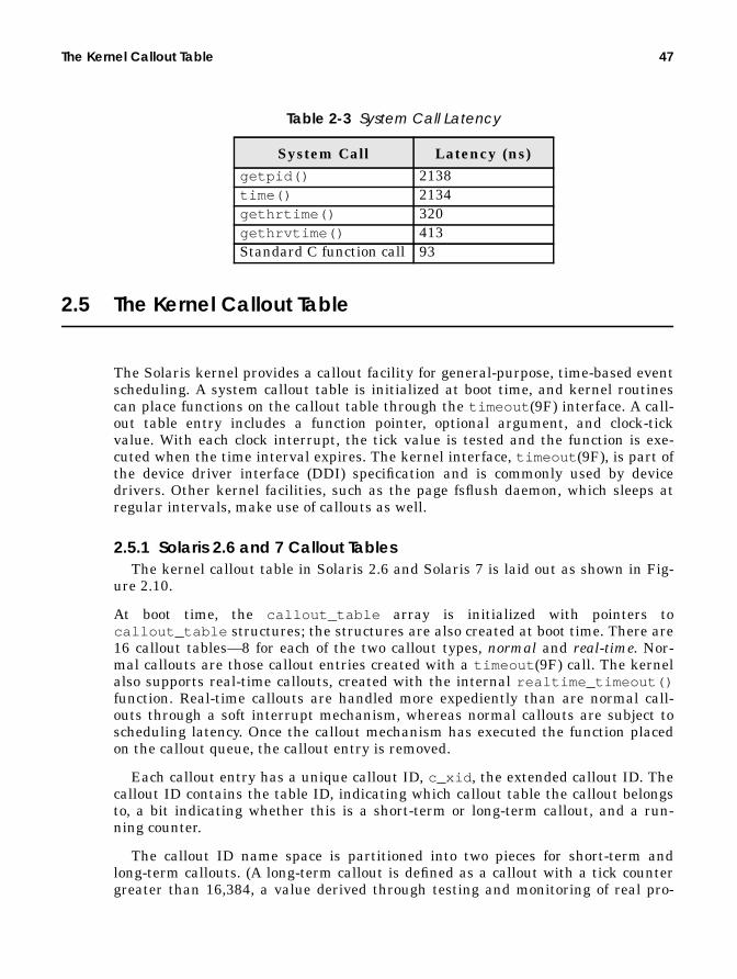
The Kernel Callout Table 47
2.5 The Kernel Callout Table
The Solaris kernel provides a callout facility for general-purpose, time-based eventscheduling. A system callout table is initialized at boot time, and kernel routinescan place functions on the callout table through the timeout (9F) interface. A call-out table entry includes a function pointer, optional argument, and clock-tickvalue. With each clock interrupt, the tick value is tested and the function is exe-cuted when the time interval expires. The kernel interface, timeout (9F), is part ofthe device driver interface (DDI) specification and is commonly used by devicedrivers. Other kernel facilities, such as the page fsflush daemon, which sleeps atregular intervals, make use of callouts as well.
2.5.1 Solaris 2.6 and 7 Callout TablesThe kernel callout table in Solaris 2.6 and Solaris 7 is laid out as shown in Fig-
ure 2.10.
At boot time, the callout_table array is initialized with pointers tocallout_table structures; the structures are also created at boot time. There are16 callout tables—8 for each of the two callout types, normal and real-time. Nor-mal callouts are those callout entries created with a timeout (9F) call. The kernelalso supports real-time callouts, created with the internal realtime_timeout()function. Real-time callouts are handled more expediently than are normal call-outs through a soft interrupt mechanism, whereas normal callouts are subject toscheduling latency. Once the callout mechanism has executed the function placedon the callout queue, the callout entry is removed.
Each callout entry has a unique callout ID, c_xid , the extended callout ID. Thecallout ID contains the table ID, indicating which callout table the callout belongsto, a bit indicating whether this is a short-term or long-term callout, and a run-ning counter.
The callout ID name space is partitioned into two pieces for short-term andlong-term callouts. (A long-term callout is defined as a callout with a tick countergreater than 16,384, a value derived through testing and monitoring of real pro-
Table 2-3 System Call Latency
System Call Latency (ns)getpid() 2138time() 2134gethrtime() 320gethrvtime() 413Standard C function call 93

48 Kernel Services
duction systems.) This partitioning prevents collisions on the callout ID, which canresult from the high volume of timeout (9f) calls typically generated by a runningsystem. It’s possible to run out of unique callout IDs, so IDs can be recycled. Forshort-term callouts, ID recycling is not a problem; a particular callout will likelyhave been removed from the callout table before its ID gets reused. A long-termcallout could collide with a new callout entry reusing its ID.
High-volume, short-term callout traffic is handled on a callout table withshort-term callouts, and the relatively few long-term callouts are maintained ontheir own callout table. The callout table maintains a ct_short_id andct_long_id , to determine if a callout table is supporting long-term or short-termcallout entries.
The short and long IDs are set to an initial value at boot time in each callout tablestructure, with short IDs ranging from 0x10000000 to 0x1000000f and long IDs
callout_tablect_lockct_freelistct_curtimect_runtimect_threadpoolct_typect_short_idct_long_idct_idhash[]ct_lbhashp[]
ct_lockct_freelistct_curtimect_runtimect_threadpoolct_typect_short_idct_long_idct_idhash[]ct_lbhashp[]
callout_table_t
*c_idnext*c_idprev*c_lbnext*c_lbprevc_xidc_runtime(*c_func)*c_argc_executorc_done
*c_idnext*c_idprev*c_lbnext*c_lbprevc_xidc_runtime(*c_func)*c_argc_executorc_done
*c_idnext*c_idprev*c_lbnext*c_lbprevc_xidc_runtime(*c_func)*c_argc_executorc_done
*c_idnext*c_idprev*c_lbnext*c_lbprevc_xidc_runtime(*c_func)*c_argc_executorc_done
*c_idnext*c_idprev*c_lbnext*c_lbprevc_xidc_runtime(*c_func)*c_argc_executorc_done
callout structures
callout freelist
callout ID hashlist
callout lbolt value hashlist
short-term callouts
long-term callouts
callout_table_t
normalcallouts,0 - 7.
real-timecallouts,8 -15.
Figure 2.10 Solaris 2.6 and Solaris 7 Callout Tables
*c_idnext*c_idprev*c_lbnext*c_lbprevc_xidc_runtime(*c_func)*c_argc_executorc_done

The Kernel Callout Table 49
ranging from 0x30000000 to 0x3000000f. The other callout table structure fieldsset at boot time are the ct_type field (eight each of normal or real-time) and thect_runtime and ct_curtime , both set to the current lbolt value when the ini-tialization occurs.
The callout entries, each represented by a callout structure, are linked to a call-out table through the ct_idhash[] and ct_lbhash[] arrays, where each arrayelement is either null or a pointer to a callout structure. The callout entries arestored on each array; one hashes on the callout ID, the other hashes on the lboltvalue. At initialization, the kernel also creates two callout threads with each call-out table. The callout threads are signalled through a condition variable when thecallout_schedule() function executes (called from the clock handler) if thereare functions with expired timers that need to execute.
As we alluded to, the insertion and removal of callout table entries by the time-out (9F) function is a regular and frequent occurrence on a running Solaris sys-tem. The algorithm for placing an entry on the callout queue goes as follows (thetimeout (9F) flow).
• timeout(function_pointer , argument_pointer , time value (delta))enters timeout_common() , with all the arguments passed to timeout (9F),along with an index into the callout_table array. The index derivation isbased on the CPU cpu_seqid (sequential ID) field and on the callout type,where normal callouts are placed on tables indexed between array locations 8through 15 (real-time callouts, 0 through 7).Basically, the algorithm causes callout entries to cycle through indexes 8through 15 as CPU IDs increment; the same CPU will reference the sameindex location every time.
• timeout_common() grabs a callout structure from the ct_freelist if oneis available, or the kernel memory allocator allocates a new one.
• The c_func and c_arg fields are set in the callout structure, and thec_runtime field is set to the sum of the current lbolt value and the passedtimer value.
• timeout_common() establishes the ID in the callout table structure, settingeither the ct_short_id or ct_long_id (if the timer is larger than 16,384,it’s a long ID).We saw earlier that the ID fields are initialized at boot time. As calloutentries are added, the algorithm essentially counts up until it wraps aroundand starts over again. This process leads to the reuse problem we just dis-cussed, which is why we have short-term and long-term IDs.
• The c_xid in the callout structure is set to the same ID value as the callouttable ID.

50 Kernel Services
• The algorithm inserts a callout entry (callout structure) into the callout tableby adding the entry to both the ct_idhash[] and ct_lbhash[] arrays inthe callout table. It derives the array index by hashing on the ID forct_idhash[] placement and hashing on the c_runtime value set in thecallout structure for the entry for ct_lbhash[] . If the array index alreadyhas a pointer, the algorithm links the callout structure by means of the nextand prev pointers.
The callout entry is now established on the callout table, and timeout (9F) returnsthe ID to the calling function. The sequence of events for realtime_timeout() isthe same.
The work done when callout_schedule() is called from the clock interrupthandler essentially happens through multiple loops. The outer loop hits all thecallout tables, and the inner loop hits the callout entries in the table.
• A local function variable set to the current lbolt value is used for entry tothe inner loop, and the callout entries’ c_runtime values determine whetherthe callouts are due for execution.
• If the callout is not due or is already running, the code moves on to the nextentry. Otherwise, it’s time for the function in the callout entry to run.
• For normal callout types, a condition variable signal function is set to wakeup one of the callout threads to execute the function. For real-time callouts,the kernel softcall() function is invoked to generate a soft interrupt,which will interrupt a processor, resulting in the function executing withoutgoing through the dispatcher.
• Once the callout table is processed in the inner loop, the outer loop moves thecode on to the next callout table. A mutex lock (ct_lock ) is acquired in theinner loop to prevent another processor from processing the same callouttable at the same time. The mutex is released when the inner loop throughthe callout table is completed.
• The callout threads created at initialization (two per callout table) then loop,waiting for the ct_threadpool condition variable. They’re signalled throughthe condition variable when a normal callout entry is due to execute (asabove), at which point they call the callout_execute() function.callout_execute() is also invoked through the softcall() interruptfunction to run a function placed on a callout table byrealtime_timeout() .To reiterate, a normal callout can be exposed to some additional latency forthe callout threads to be scheduled once they are signalled by the conditionvariable. The softcall() method will force a processor into thecallout_execute() function sooner through the interrupt facility.

The Kernel Callout Table 51
• callout_execute() will loop again through the callout table, testing theconditions for function execution. It’s possible that another processor tookcare of things in the interim between function calls and lock releases, so thekernel tests the time values and running flag for the entries in the tablebefore actually executing the function.
• Assuming that it is time to run, callout_execute() sets theCALLOUT_EXECUTINGflag in the callout entry’s c_xid field, and the functionis invoked.
• The callout entry is then removed from the callout table, the callout struc-ture is placed on the freelist (ct_freelist ), and a condition variable isbroadcasted if any threads are sleeping on the c_done condition variable.This condition variable is part of the callout entry and provides a method ofgenerating a notification that a function placed on the callout table has exe-cuted.
The kernel also provides an untimeout (9F) interface, which will remove a call-out. untimeout (9F) is passed the ID (which was returned from timeout (9F)when the function was placed on the callout table). The entry is located by meansof the ct_idhash[] array and removed, with the callout structure being added tothe freelist. Callout entries added by realtime_timeout (9F) can also be removedwith untimeout (9F). There is no separate function for the removal of real-timecallouts.
2.5.2 Solaris 2.5.1 Callout Tables
Callout tables in Solaris 2.5.1 are functionally identical to those we described forSolaris 2.6 and Solaris 7; the implementation is different. Solaris 2.5.1 maintainstwo callout tables—one for normal callouts and one for real-time callouts—whichare initialized at boot time. The overall structure of callout tables in Solaris 2.5.1is illustrated in Figure 2.11.
As you can see, many of the structure fields are identical in name (and func-tion) to those described previously. The link to each callout table is made with acallout_state pointer (normal callout table) and an rt_callout_statepointer (real-time callout table, not shown in the figure, but identical). The tablesimplement an array of 256 buckets; each bucket links to a callout structure andmaintains the ID for the entry.
The initialization process happens at boot time, with two distinct setup phases:one for the normal callout table and one for the real-time callout table. Thecs_bucket[] array of the callout_state structure (the callout table, really) isimplemented as a circular, singly linked list. At initialization, the b_first pointeris set to point back to itself, and as callouts are added to the bucket, the last call-out’s c_next will reference the first entry on the bucket. The ID fields represent along and a short ID name space, as in the Solaris 2.6 and 7 implementation. Thesefields are set to initial values in each bucket head during the init phase.
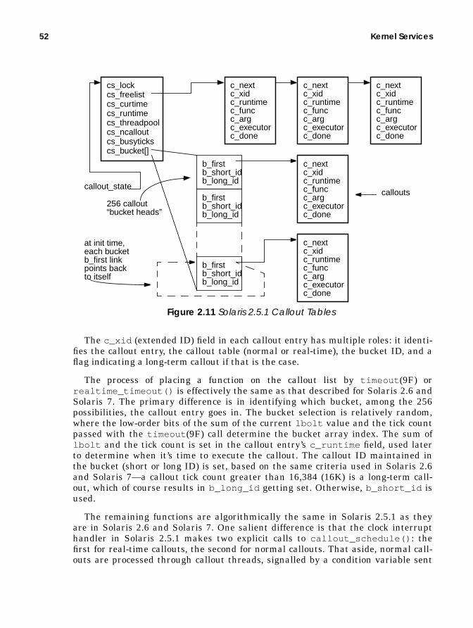
52 Kernel Services
The c_xid (extended ID) field in each callout entry has multiple roles: it identi-fies the callout entry, the callout table (normal or real-time), the bucket ID, and aflag indicating a long-term callout if that is the case.
The process of placing a function on the callout list by timeout (9F) orrealtime_timeout() is effectively the same as that described for Solaris 2.6 andSolaris 7. The primary difference is in identifying which bucket, among the 256possibilities, the callout entry goes in. The bucket selection is relatively random,where the low-order bits of the sum of the current lbolt value and the tick countpassed with the timeout (9F) call determine the bucket array index. The sum oflbolt and the tick count is set in the callout entry’s c_runtime field, used laterto determine when it’s time to execute the callout. The callout ID maintained inthe bucket (short or long ID) is set, based on the same criteria used in Solaris 2.6and Solaris 7—a callout tick count greater than 16,384 (16K) is a long-term call-out, which of course results in b_long_id getting set. Otherwise, b_short_id isused.
The remaining functions are algorithmically the same in Solaris 2.5.1 as theyare in Solaris 2.6 and Solaris 7. One salient difference is that the clock interrupthandler in Solaris 2.5.1 makes two explicit calls to callout_schedule() : thefirst for real-time callouts, the second for normal callouts. That aside, normal call-outs are processed through callout threads, signalled by a condition variable sent
cs_lockcs_freelistcs_curtimecs_runtimecs_threadpoolcs_ncalloutcs_busytickscs_bucket[]
c_nextc_xidc_runtimec_funcc_argc_executorc_done
c_nextc_xidc_runtimec_funcc_argc_executorc_done
c_nextc_xidc_runtimec_funcc_argc_executorc_done
b_firstb_short_idb_long_id
b_firstb_short_idb_long_id
b_firstb_short_idb_long_id
c_nextc_xidc_runtimec_funcc_argc_executorc_done
c_nextc_xidc_runtimec_funcc_argc_executorc_done
256 callout“bucket heads”
callout_statecallouts
at init time,each bucketb_first linkpoints backto itself
Figure 2.11 Solaris 2.5.1 Callout Tables

The Kernel Callout Table 53
from the callout schedule loop; real-time callouts are handled through the inter-rupt facility by the softint() interface.
You can examine the callout table on a running system (all releases) with thecallout function in the crash (1M) utility.
Note that the example output from the callout function in crash (1M) is not a com-plete listing. Note, too, that the output is from a 64-bit Solaris 7 system, which iswhy the ARGUMENT, TIME, and ID columns are 8-byte (64-bit) data types. On a32-bit kernel, they are 32-bit data types.
Some of the kernel functions that you will consistently find on the callout tableof a running Solaris system include the following.
• polltime — A real-time callout. Set from the poll (2) system call and basedon the poll interval. polltime() wakes up a thread waiting on a poll event.
• realitexpire — A real-time callout. Used in the real-time interval timersupport when a timer is set. Callout ticks are derived from timer value.realitexpire() generates the SIGALRM to the process.
• setrun — A real-time callout. Placed on the callout queue by sleep/wakeupcode (condition variables) to force a thread wakeup when the sleep event hasa timeout value; for example, an aiowait (2) call can specify a maximum tickcount to wait for the I/O to complete. aiowait (2) with a timeout specificityuses a timed condition variable, which in turn places a setrun() event onthe callout queue to force a thread wakeup if the time expires before the I/Ohas completed.
• schedpaging — A normal callout. Part of the pageout subsystem in the VMsystem, used to manage the pageout rate.
• mi_timer_fire — A normal callout. Part of the STREAMS-based TCP/IPprotocol support. mi_timer_fire() generates regular message block pro-cessing through a STREAMS queue.
# /etc/crashdumpfile = /dev/mem, namelist = /dev/ksyms, outfile = stdout> calloutFUNCTION ARGUMENT TIME IDpolltime 00000300008df260 00000000006a4971 7ffffffffff761f0realitexpire 000003000090ed80 00000000006adf39 7ffffffffff79890setrun 000002a10034fd60 000000000069bd97 3fffffffff925a31schedpaging 0000000000000000 000000000069bd0f 3fffffffffb7c618mi_timer_fire 0000030000a36820 000000000069bd20 3fffffffffb7c628sigalarm2proc 0000030000974ac0 000000000069be19 3fffffffffb7c648ts_update 0000000000000000 000000000069bd4c 3fffffffffb7c658seg_pupdate 0000000000000000 000000000069c139 3fffffffffb7cb88kmem_update 0000000000000000 000000000069c139 3fffffffffcb3069..

54 Kernel Services
• sigalarm2proc — A normal callout. The alarm (2) system call placessigalarm2proc on the callout queue to generate a SIGALRMwhen the timerexpires.
• ts_update — A normal callout. Checks a list of timeshare and interactiveclass threads and updates their priority as needed.
• seg_pupdate — A normal callout. Used by the address space segmentreclaim thread to find pagelocked pages that have not been used in a whileand reclaim them.
• kmem_update — A normal callout. Performs low-level kernel memory alloca-tor management.
This is by no means a complete list of all the kernel functions placed on the calloutqueue, and of course you will typically see several of the same functions on thecallout queue at the same time, with different IDs and timeout values.
2.6 The System Clock
The Solaris kernel relies on hardware timer interrupts for general housekeepingchores that need to be done at regular intervals. For example, the system clocktriggers the dispatcher to recalculate process priorities at regular intervals andalso initiates callout queue processing.
The kernel (software) sets up the programmable interrupt generator (hard-ware) to generate a clock interrupt at regular intervals, by default 100 times persecond. The clock interrupts at interrupt level 10 (SPARC); nothing else on the sys-tem generates interrupts at this level. With each clock interrupt, a handler isentered. It performs the following functions:
• Sets available kernel anon space (anon_free ) value, for tracking and report-ing.
• Sets free memory (freemem ) value, for tracking and reporting.
• Adjusts the time of day clock for possible jitter.
• Calculates CPU usage (user, system, idle, and wait I/O) and system dispatch(run queue) queue size.
• Does clock-tick processing for the thread running on the CPU (except theCPU running the clock interrupt thread) and threads that are exiting. Notethat kernel threads that do not have an associated LWP—kernel servicethreads that are an integral part of the operating system—are not subject totick processing.

The System Clock 55
• Updates the lbolt counter. lbolt counts the number of clock ticks sinceboot.
• Processes the kernel callout table (described in the next section).
• If on a one-second interval, calculates kernel swap parameters (free,reserved, and allocated swap) and adjusts systemwide run queue size andswap queue size.
Once the clock interrupt handling is completed, the clock interrupt thread is con-text-switched off the processor, and the thread that was executing when the inter-rupt occurred resumes.
2.6.1 Process Execution Time Statistics
The CPU usage work and thread tick processing is done on a per-CPU basis; thecode loops through the list of online processors and does the work for each CPU.Usage information is maintained in the cpu[] array in each CPU’s sysinfostructure. The four-member cpu[] array stores an integer value, one for each ofUSER, SYSTEM, IDLE , and WAIT—the four possible states that the CPU will be in.A CPU in the QUIESCEDstate is charged with idle time. A CPU running an inter-rupt thread is charged with system time. A CPU running its idle thread is chargedwith idle time unless the cpu_syswait.iowait value is set; in that case, theCPU is charged wait I/O time.
cpu_syswait.iowait is set in the biowait() routine, which is called fromthe file system support code when a buffered I/O is issued (see Part III, The SolarisFile I/O System for specifics on buffered I/O). biowait() is also called from thedisk drivers in the kernel; thus, wait I/O time reflects I/O through the file systemas well as raw disk I/O; wait I/O reflects disk I/O only, and network I/O is notreflected. The algorithm for calculating wait I/O was flawed in releases prior toSolaris 7, and CPUs that were idle may be charged incorrectly with wait I/O time.Finally, if a thread that is not the idle thread or an interrupt thread is running ona CPU, the state of the thread is checked to determine if the CPU should becharged with user time (the thread is executing in user mode) or system time.
The last bullet item in the previous section indicates that some of the clockinterrupt processing is not done in every clock interrupt (100 times a second), butrather at one-second intervals. For the services indicated, one-second granularityis sufficient.
Tick processing is done for each kernel thread (if that thread is not an interrupthandler or an operating system kernel thread) running on a CPU. Each kernelthread maintains a t_pctcpu (percent of CPU time) and t_lbolt value, wheret_pctcpu is used for per-thread usage information (e.g., accounting) and t_lboltprovides a point of reference for tick processing. The kernel determines whether it

56 Kernel Services
is necessary to do tick processing for the thread by comparing t_lbolt againstlbolt .
The clock_tick() code is passed the kernel thread ID and invokes the schedul-ing-class-specific clock-tick function, that is, ts_tick() for timeshare and interac-tive class threads and rt_tick() for real-time class threads. These functions arediscussed in Chapter 4, “The Kernel Dispatcher.” Briefly, the functions determine ifthe thread has used up its time quantum, and they take the thread off the proces-sor if it has. Back in the clock_tick() function, the following actions are per-formed.
• The user or system time values in the process and the LWP are incremented,based on the mode the thread is in (system or user). Note that if a thread isexecuting in short bursts between clock samples, not all CPU time will beaccounted for.
• The per-thread interval timers are tested (profiling and virtual timer, enabledwith the setitimer (2) system call), and the appropriate signal—SIGPROForSIGVTALRM—is sent if either timer has expired.
• The per-process CPU resource limit is checked (maximum CPU seconds theprocess can consume), and if that threshold has been reached, a SIGXCPUissent.
• The process memory usage is updated in the uarea u_mem , which reflects thetotal address space size of the process.
The update completes the clock-tick processing for the thread.
2.6.2 High-Resolution Clock Interrupts
By default, a system clock interval of 10 milliseconds (100 interrupts per second) isused. You can set a kernel parameter, hires_tick , in the /etc/system file toincrease the clock interrupt frequency to 1000 interrupts per second (sethires_tick = 1 in /etc/system ). Increasing the clock frequency results in thesystem entering the dispatcher (among other things) more frequently. Exercisegreat care if you are considering setting high-resolution ticks—they can reducesystem performance dramatically. As with any system tunable, this setting shouldnever, ever be made on a production system without extensive testing first.
if (lbolt - t_lbolt) = 0 no need to do tick processingelse set t_pctcpu t_lbolt = lbolt call clock_tick(current thread)

The System Clock 57
2.6.3 High-Resolution Timer
The kernel also maintains a high-resolution timer for nanosecond-level timingfunctions. On UltraSPARC-based systems, the hardware TICK register is used; it isincremented with every processor clock tick, that is, every 2.5 nanoseconds on a400 MHz processor. An internal gethrestime() (get high-resolution time) func-tion is used in a few areas of the kernel where fine-grained time is needed, such asthe support for real-time interval timers (the setitimer (2) system call with theITIMER_REAL flag). A gethrtime (3C) interface provides programs with nanosec-ond-level granularity for timing. The gethrtime (3C) function has an optimizedcode path to read the TICK register and return a normalized (converted to nanosec-onds) value to the calling program.
2.6.4 Time-of-Day Clock
All computer systems—from desktop PCs to high-end multiprocessor systems—have a clock circuit of some sort. SPARC-based systems include clock circuitry inthe EEPROM area of the hardware (e.g., the Mostek 48T59 clock chip is used onUltraSPARC-based systems). This Time-of-Day (TOD) clock chip is addressable bythe kernel as part of the firmware address space and has a hardware register spec-ification; a kernel interface to the TOD hardware is implemented as a TOD devicedriver.
The chip itself implements several registers, readable and writable by the ker-nel through the device driver, that provide multiple counters for the numeric com-ponents that make up the date and time (e.g., minute-of-the-hour, hour-of-the-day,day-of-the-week, month-of-the-year, etc.).

58 Kernel Services
Figure 2.12 illustrates the hardware and software hierarchy for the TOD.
Figure 2.12 Time-of-Day Clock on SPARC Systems
Each component of a day and time value is stored as a separate counter value inthe clock chip, and each counter increments the next logical value when it reachesits top value, for example, seconds count values 0–59, then increment minutes andrestart at 0. Executing the date (1) command to set the date calls the stime (2)system call, which in turn calls the tod_set() device driver interface that setsthe values in the TOD clock hardware.
To comply with industry-standard interfaces (system calls and library rou-tines), the kernel provides functions for converting the date values read from theclock hardware to the Unix convention of the number of seconds since the epoch,and vice versa.
commands — date(1)
EEPROM
clk_alm_secsclk_alm_minsclk_alm_hoursclk_alm_days..clk_sec [0 - 59]clk_min [0 - 59]clk_hour [0 - 23]clk_day [1 - 31]clk_weekday [1 - 7]clk_month [1 - 12]clk_year [0 - 99]
TODcircuitry
TOD KERNEL DRIVER
time and datesystem calls —time(2) & stime(2)
hardware
Kernelcontext
time & date library functions —ctime(3c), asctime(3c), gmtime(3c),localtime(3c)
regi
ster
s
Processcontext

3
KERNELSYNCHRONIZATION
PRIMITIVES
In this chapter, we continue our discussion of core kernel facilities, with anexamination of the synchronization objects implemented in the Solaris kernel.
3.1 Synchronization
Solaris runs on a variety of different hardware platforms, including multiproces-sor systems based on both the SPARC and Intel processors. Several multiproces-sor architectures in existence today offer various trade-offs in performance andengineering complexity in both hardware and software. The current multiproces-sor architecture that Solaris supports is the symmetric multiprocessor (SMP) andshared memory architecture, which implements a single kernel shared by all theprocessors and a single, uniform memory address space. To support such an archi-tecture, the kernel must synchronize access to critical data to maintain data integ-rity, coherency, and state. The kernel synchronizes access by defining a lock for aparticular kernel data structure or variable and requiring that code reading orwriting the data must first acquire the appropriate lock. The holder of the lock isrequired to release the lock once the data operation has been completed.
The synchronization primitives and associated interfaces are used by virtuallyall kernel subsystems: device drivers, the dispatcher, process and thread supportcode, file systems, etc. Insight into what the synchronization objects are and howthey are implemented is key to understanding one of the core strengths of theSolaris kernel—scalable performance on multiprocessor systems. An equallyimportant component to the scalability equation is the avoidance of locks alto-
59

60 Kernel Synchronization Primitives
gether whenever possible. The use of synchronization locks in the kernel is con-stantly being scrutinized as part of the development process in kernel engineering,with an eye to minimizing the number of locks required without compromisingdata integrity.
Several alternative methods of building parallel multiprocessor systems haveemerged in the industry over the years. So, in the interest of conveying the issuessurrounding the implementation, we need to put things in context. First, we take abrief look at the different parallel systems architectures that are commerciallyavailable today, and then we turn to the specifics of support for multiprocessorarchitectures by the Solaris kernel.
3.2 Parallel Systems Architectures
Multiprocessor (MP) systems from Sun (SPARC-processor-based), as well as sev-eral Intel-based MP platforms, are implemented as symmetric multiprocessor(SMP) systems. Symmetric multiprocessor describes a system in which apeer-to-peer relationship exists among all the processors (CPUs) on the system. Amaster processor, defined as the only CPU on the system that can execute operat-ing system code and field interrupts, does not exist. All processors are equal. TheSMP acronym can also be extended to mean Shared Memory Multiprocessor, whichdefines an architecture in which all the processors in the system share a uniformview of the system’s physical address space and the operating system’s virtualaddress space. That is, all processors share a single image of the operating systemkernel. Sun’s multiprocessor systems meet the criteria for both definitions.
Alternative MP architectures alter the kernel’s view of addressable memory indifferent ways. Massively parallel processor (MPP) systems are built on nodes thatcontain a relatively small number of processors, some local memory, and I/O. Eachnode contains its own copy of the operating system; thus, each node addresses itsown physical and virtual address space. The address space of one node is not visi-ble to the other nodes on the system. The nodes are connected by a high-speed,low-latency interconnect, and node-to-node communication is done through anoptimized message passing interface. MPP architectures require a new program-ming model to achieve parallelism across nodes.
The shared memory model does not work since the system’s total address spaceis not visible across nodes, so memory pages cannot be shared by threads runningon different nodes. Thus, an API that provides an interface into the message pass-ing path in the kernel must be used by code that needs to scale across the variousnodes in the system.
Other issues arise from the nonuniform nature of the architecture with respectto I/O processing, since the I/O controllers on each node are not easily made visi-ble to all the nodes on the system. Some MPP platforms attempt to provide the
Parallel Systems Architectures 61
illusion of a uniform I/O space across all the nodes by using kernel software, butthe nonuniformity of the access times to nonlocal I/O devices still exists.
NUMA and ccNUMA (nonuniform memory access and cache coherent NUMA)architectures attempt to address the programming model issue inherent in MPPsystems. From a hardware architecture point of view, NUMA systems resembleMPPs—small nodes with few processors, a node-to-node interconnect, local mem-ory, and I/O on each node. Note it is not required that NUMA/ccNUMA or MPPsystems implement small nodes (nodes with four or fewer processors). Many imple-mentations are built that way, but there is no architectural restriction on the nodesize.
On NUMA/ccNUMA systems, the operating system software provides a singlesystem image, where each node has a view of the entire system’s memory addressspace. In this way, the shared memory model is preserved. However, the nonuni-form nature of speed of memory access (latency) is a factor in the performance andpotential scalability of the platform. When a thread executing on a processor nodeon a NUMA or ccNUMA system incurs a page fault (references an unmapped mem-ory address), the latency involved in resolving the page fault varies according towhether the physical memory page is on the same node of the executing thread oron a node somewhere across the interconnect. The latency variance can be sub-stantial. As the level of memory page sharing increases across threads executingon different nodes, a potentially higher volume of page faults needs to be resolvedfrom a nonlocal memory segment. This problem adversely affects performance andscalability.
The three different parallel architectures can be summarized as follows.
• SMP — Symmetric multiprocessor with a shared memory model; single ker-nel image.
• MPP — Message-based model; multiple kernel images.
• NUMA/ccNUMA — Shared memory model; single kernel image.
Figure 3.1 illustrates the different architectures.
The challenge in building an operating system that provides scalable perfor-mance when multiple processors are sharing a single image of the kernel andwhen every processor can run kernel code, handle interrupts, etc., is to synchro-nize access to critical data and state information. Scalable performance, or scal-ability, generally refers to accomplishing an increasing amount of work as morehardware resources are added to the system. If more processors are added to amultiprocessor system, an incremental increase in work is expected, assuming suf-ficient resources in other areas of the system (memory, I/O, network).
To achieve scalable performance, the system must be able to support multipleprocessors executing operating system code concurrently. Whether that executionis in device drivers, interrupt handlers, the threads dispatcher, file system code,

62 Kernel Synchronization Primitives
virtual memory code, etc., is, to a degree, load dependent. Concurrency is key toscalability.
The preceding discussion on parallel architectures only scratched the surface ofa very complex topic. Entire texts discuss parallel architectures exclusively, youshould refer to them for additional information. See, for example, [11], [21] and[23].
Figure 3.1 Parallel Systems Architectures
The difficulty is maintaining data integrity of data structures, kernel variables,data links (pointers), and state information in the kernel. We cannot, for example,allow threads running on multiple processors to manipulate pointers to the samedata structure on the same linked list all at the same time. We should prevent oneprocessor from reading a bit of critical state information (e.g., is a processoronline?) while a thread executing on another processor is changing the same state
System Interconnect, either bus or
Shared memory, symmetric (SMP)system with uniform memory andI/O access. Single kernel imageshared by all processors — singleaddress space view.
A single multiprocessor system
cross-bar design. Cache-coherent
A single multiprocessor (oruniprocessor) node
This hardware architecture couldbe an MPP or NUMA/ccNUMAsystem.MPP — multiple OS images, multipleaddress space views, nonunifomI/O access.NUMA/ccNUMA — single OS image,single addess space view, non-uniform memory, nonuniform I/Owhen interconnect is traversed.
Interconnect is message-basedon MPP platforms; memory-based, cache-coherent onNUMA/ccNUMA.
protocol for data transfers to/frommemory, processors, and I/O. Veryhigh, sustainable bandwidth withuniform access times (latency).
Mem
ory
I/O
Mem
ory
I/O
Mem
ory
I/O
Mem
ory
I/O
Mem
ory
I/O
Mem
ory
I/O
Mem
ory
I/O
Mem
ory
I/O
Mem
ory
I/O
Mem
ory
I/O
Mem
ory
I/O
Mem
ory
I/O
CPU
(s)
CPU
(s)
CPU
(s)
CPU
(s)
CPU
(s)
CPU
(s)
CPU
(s)
CPU
(s)
CPU
(s)
CPU
(s)
CPU
(s)
CPU
(s)

Hardware Considerations for Locks and Synchronization 63
data (e.g., in the process of bringing online a processor that is still in a state tran-sition).
To solve the problem of data integrity on such systems, the kernel implementslocking mechanisms. It requires that all operating system code be aware of thenumber and type of locks that exist in the kernel and comply with the locking hier-archy and rules for acquiring locks before writing or reading kernel data. It isworth noting that the architectural issues of building a scalable kernel are notvery different from those of developing a multithreaded application to run on ashared memory system. Multithreaded applications must also synchronize accessto shared data, using the same basic locking primitives and techniques that areused in the kernel. Other synchronization problems, such as dealing with inter-rupts and trap events, exist in kernel code and make the problem significantlymore complex for operating systems development, but the fundamental problemsare the same.
3.3 Hardware Considerations for Locks and Synchronization
Hardware-specific considerations must enter into the implementation of lock prim-itives on a system. The first consideration has to do with the processor’s instruc-tion set and the availability of machine instructions suitable for locking code. Thesecond deals with the visibility of a lock’s state when it is examined by executingkernel threads.
To understand how these considerations apply to lock primitives, keep in mindthat a lock is a piece of data at a specific location in the system’s memory. In itssimplest form, a lock is a single byte location in RAM. A lock that is set, or held(has been acquired), is represented by all the bits in the lock byte being 1’s (lockvalue 0xFF). A lock that is available (not being held) is the same byte with all 0’s(lock value 0x00). This explanation may seem quite rudimentary, but is crucial tounderstanding the text that follows.
Most modern processors shipping today provide some form of byte-leveltest-and-set instruction that is guaranteed to be atomic in nature. The instructionsequence is often described as read-modify-write, that is, the referenced memorylocation (the memory address of the lock) is read, modified, and written back inone atomic operation. In RISC processors (such as Sun SPARC), reads are loadoperations and writes are store operations. An atomic operation is required for con-sistency. An instruction that has atomic properties means that no other store oper-ation is allowed between the load and store of the executing instruction. Mutexand RW lock operations must be atomic, such that when the instruction executionto get the lock is complete, we either have the lock or have the information we needto determine that the lock is already being held. Consider what could happen with-out an instruction that has atomic properties. A thread executing on one processorcould issue a load (read) of the lock, and while it is doing a test operation to deter-
64 Kernel Synchronization Primitives
mine if the lock is held or not, another thread executing on another processorissues a lock call to get the same lock at the same time. If the lock is not held, boththreads would assume the lock is available and would issue a store to hold thelock. Obviously, more than one thread cannot own the same lock at the same time,but that would be the result of such a sequence of events. Atomic instructions pre-vent such things from happening.
SPARC processors implement memory access instructions that provide atomictest-and-set semantics for mutual exclusion primitives, as well as instructions thatcan force a particular ordering of memory operations (more on the latter feature ina moment). UltraSPARC processors (the SPARC V9 instruction set) provide threememory access instructions that guarantee atomic behaviour: ldstub (load andstore unsigned byte), cas (compare and swap), and swap (swap byte locations).These instructions differ slightly in their behavior and the size of the datum theyoperate on.
Figure 3.2 illustrates the ldstub and cas instructions. The swap instruction(not shown) simply swaps a 32-bit value between a hardware register and a mem-ory location, similar to what cas does if the compare phase of the instructionsequence is equal.
The implementation of locking code with the assembly language test-and-setstyle of instructions requires a subsequent test instruction on the lock value, whichis retrieved with either a cas or ldstub instruction.
For example, the ldstub instruction retrieves the byte value (the lock) frommemory and stores it in the specified hardware register. Locking code must testthe value of the register to determine if the lock was held or available when theldstub executed. If the register value is all 1’s, the lock was held, so the code mustbranch off and deal with that condition. If the register value is all 0’s, the lock wasnot held and the code can progress as being the current lock holder. Note that inboth cases, the lock value in memory is set to all 1’s, by virtue of the behavior ofthe ldstub instruction (store 0xFF at designated address). If the lock was alreadyheld, the value simply didn’t change. If the lock was 0 (available), it will nowreflect that the lock is held (all 1’s). The code that releases a lock sets the lockvalue to all 0’s, indicating the lock is no longer being held.

Hardware Considerations for Locks and Synchronization 65
Figure 3.2 Atomic Instructions for Locks on SPARC
The Solaris lock code uses assembly language instructions when the lock code isentered. The basic design is such that the entry point to acquire a lock enters anassembly language routine, which uses either ldstub or cas to grab the lock. Theassembly code is designed to deal with the simple case, meaning that the desiredlock is available. If the lock is being held, a C language code path is entered to dealwith this situation. We describe what happens in detail in the next few sectionsthat discuss specific lock types.
The second hardware consideration referred to earlier has to do with the visibil-ity of the lock state to the running processors when the lock value is changed. It iscritically important on multiprocessor systems that all processors have a consis-tent view of data in memory, especially in the implementation of sychronizationprimitives—mutex locks and reader/writer (RW) locks. In other words, if a threadacquires a lock, any processor that executes a load instruction (read) of that mem-ory location must retrieve the data following the last store (write) that was issued.The most recent state of the lock must be globally visible to all processors on thesystem.
Modern processors implement hardware buffering to provide optimal perfor-mance. In addition to the hardware caches, processors also use load and store buff-
memory
load from memoryto register
store value FF (hex)in addressed memory
hardware register The ldstub (load-store unsigned byte)instruction operates on a byte (8 bits).It loads a byte value from memory toa register and stores all 1’s (FF hex)into the byte location atomically.
location
memory
compare value inregister with valuein memory.
if the values are equal, swapvalue in memory with value insecond hardware register
The cas (compare and swap) instructionoperates on words (32 bits) ordouble words (64 bits). If the valuecontained in the first processorregister is equal to the value in thememory location, the memory datais swapped with the value in a second reg.
processor hardware registers
a processor’s

66 Kernel Synchronization Primitives
ers to hold data being read from (load) or written to (store) memory, in order tokeep the instruction pipeline running and not have the processor stall waiting fordata or a data write-to-memory cycle. The data hierarchy is illustrated in Figure3.3.
Figure 3.3 Hardware Data Hierarchy
The illustration in Figure 3.3 does not depict a specific processor; it is a genericrepresentation of the various levels of data flow in a typical modern high-endmicroprocessor. It is intended to show the flow of data to and from physical mem-ory from a processor’s main execution units (integer units, floating point units,etc.).
The sizes of the load/store buffers vary across processor implementations, butthey are typically several words in size. The load and store buffers on each proces-sor are visible only to the processor they reside on, so a load issued by a processorthat issued the store fetches the data from the store buffer if it is still there. How-ever, it is theoretically possible for other processors that issue a load for that datato read their hardware cache or main memory before the store buffer in thestore-issuing processor was flushed. Note that the store buffer we are referring tohere is not the same thing as a level 1 or level 2 hardware instruction and datacache. Caches are beyond the store buffer; the store buffer is closer to the execu-tion units of the processor. Physical memory and hardware caches are kept consis-tent on SMP platforms by a hardware bus protocol. Also, many caches areimplemented as write-through caches (as is the case with the level 1 cache in SunUltraSPARC), so data written to cache causes memory to be updated.
The implementation of a store buffer is part of the memory model implementedby the hardware. The memory model defines the constraints that can be imposedon the order of memory operations (loads and stores) by the system. Many proces-sors implement a sequential consistency model, where loads and stores to memoryare executed in the same order in which they were issued by the processor. This
physical memory
level 2cache
load/storebuffers
level 1cache
executionunits
level 2cache
load/storebuffers
level 1cache
executionunits
level 2cache
load/storebuffers
level 1cache
executionunits Processors
load
s
stor
es

Hardware Considerations for Locks and Synchronization 67
model has advantages in terms of memory consistency, but there are performancetrade-offs with such a model because the hardware cannot optimize cache andmemory operations for speed. The SPARC architecture specification ([41]) pro-vides for building SPARC-based processors that support multiple memory models,the choice being left up to the implementors as to which memory models they wishto support. All current SPARC processors implement a Total Store Ordering (TSO)model, which requires compliance with the following rules for loads and stores.
• Loads (reads from memory) are blocking and are ordered with respect toother loads.
• Stores (writes to memory) are ordered with respect to other stores. Storescannot bypass earlier loads.
• Atomic load-stores (ldstub and cas instructions) are ordered with respect toloads.
The TSO model is not quite as strict as the sequential consistency model but not asrelaxed as two additional memory models defined by the SPARC architecture.SPARC-based processors also support Relaxed Memory Order (RMO) and PartialStore Order (PSO), but these are not currently supported by the kernel and notimplemented by any Sun systems shipping today.
A final consideration in data visibility applies also to the memory model andconcerns instruction ordering. The execution unit in modern processors can reor-der the incoming instruction stream for processing through the execution units.The goals again are performance and creation of a sequence of instructions thatwill keep the processor pipeline full.
The hardware considerations described in this section are summarized in Table3-1, along with the solution or implementation detail that applies to the particularissue.
The issues of consistent memory views in the face of processor’s load and storebuffers, relaxed memory models, and atomic test-and-set capability for locks are
Table 3-1 Hardware Considerations and Solutions for Locks
Consideration SolutionNeed for an atomic test-and-setinstruction for locking primitives.
Use of native machine instructions.ldstub and cas on SPARC, cmpx-chgl (compare/exchange long) onx86.
Data global visibility issue becauseof the use of hardware load andstore buffers and instruction reor-dering, as defined by the memorymodel.
Use of memory barrier instructions.
68 Kernel Synchronization Primitives
addressed at the processor instruction-set level. The mutex lock and RW lock prim-itives implemented in the Solaris kernel use the ldstub and cas instructions forlock testing and acquisition on UltraSPARC-based systems and use the cmpxchgl(compare/exchange long) instruction on Intel x86. The lock primitive routines arepart of the architecture-dependent segment of the kernel code.
SPARC processors provide various forms of memory barrier (membar) instruc-tions, which, depending on options that are set in the instruction, impose specificconstraints on the ordering of memory access operations (loads and stores) rela-tive to the sequence with which they were issued. To ensure a consistent memoryview when a mutex or RW lock operation has been issued, the Solaris kernel issuesthe appropriate membar instruction after the lock bits have changed.
As we move from the strongest consistency model (sequential consistency) to theweakest model (RMO), we can build a system with potentially better performance.We can optimize memory operations by playing with the ordering of memoryaccess instructions that enable designers to minimize access latency and to maxi-mize interconnect bandwidth. The trade-off is consistency, since the more relaxedmodels provide fewer and fewer constraints on the system to issue memory accessoperations in the same order in which the instruction stream issued them. So, pro-cessor architectures provide memory barrier controls that kernel developers canuse to address the consistency issues where necessary, with some level of controlon which consistency level is required to meet the system requirements. The typesof membar instructions available, the options they support, and how they fit intothe different memory models described would make for a highly technical andlengthy chapter on its own. Readers interested in this topic should read [4] and[23].
3.4 Introduction to Synchronization Objects
The Solaris kernel implements several types of synchronization objects. Locks pro-vide mutual exclusion semantics for synchronized access to shared data. Lockscome in several forms and are the primary focus of this chapter. The most com-monly used lock in the Solaris kernel is the mutual exclusion, or mutex lock, whichprovides exclusive read and write access to data. Also implemented arereader/writer (RW) locks, for situations where multiple readers are allowable butonly one writer is allowed at a time. Kernel semaphores are also employed in someareas of the kernel, where access to a finite number of resources must be man-aged. A special type of mutex lock, called a dispatcher lock, is used by the kerneldispatcher where synchronization requires access protection through a lockingmechanism, as well as protection from interrupts.
Condition variables, which are not a type of lock, are used for thread synchroni-zation and are an integral part of the kernel sleep/wakeup facility. Condition vari-

Introduction to Synchronization Objects 69
ables are introduced here and covered in detail in Chapter 5, “The KernelDispatcher.”
The actual number of locks that exist in a running system at any time isdynamic and scales with the size of the system. Several hundred locks are definedin the kernel source code, but a lock count based on static source code is not accu-rate because locks are created dynamically during normal system activity—whenkernel threads and processes are created, file systems are mounted, files are cre-ated and opened, network connections are made, etc. Many of the locks are embed-ded in the kernel data structures that provide the abstractions (processes, files)provided by the kernel, and thus the number of kernel locks will scale up linearlyas resources are created dynamically.
This design speaks to one of the core strengths of the Solaris kernel: scalabilityand scaling synchronization primitives dynamically with the size of the kernel.Dynamic lock creation has several advantages over static allocations. First, thekernel is not wasting time and space managing a large pool of unused locks whenrunning on a smaller system, such as a desktop or workgroup server. On a largesystem, a sufficient number of locks are available to sustain concurrency for scal-able performance. It is possible to have literally thousands of locks in existence ona large, busy system.
3.4.1 Synchronization Process
When an executing kernel thread attempts to acquire a lock, it will encounter oneof two possible lock states: free (available) or not free (owned, held). A requestingthread gets ownership of an available lock when the lock-specific get lock functionis invoked. If the lock is not available, the thread most likely needs to block andwait for it to come available, although, as we will see shortly, the code does notalways block (sleep), waiting for a lock. For those situations in which a thread willsleep while waiting for a lock, the kernel implements a sleep queue facility, knownas turnstiles, for managing threads blocking on locks.
When a kernel thread has completed the operation on the shared data pro-tected by the lock, it must release the lock. When a thread releases a lock, the codemust deal with one of two possible conditions: threads are waiting for the lock(such threads are termed waiters), or there are no waiters. With no waiters, thelock can simply be released. With waiters, the code has several options. It canrelease the lock and wake up the blocking threads. In that case, the first thread toexecute acquires the lock. Alternatively, the code could select a thread from theturnstile (sleep queue), based on priority or sleep time, and wake up only thatthread. Finally, the code could select which thread should get the lock next, andthe lock owner could hand the lock off to the selected thread. As we will see in thefollowing sections, no one solution is suitable for all situations, and the Solaris ker-nel uses all three methods, depending on the lock type. Figure 3.4 provides the bigpicture.

70 Kernel Synchronization Primitives
Figure 3.4 Solaris Locks — The Big Picture
Figure 3.4 provides a generic representation of the execution flow. Later we willsee the results of a considerable amount of engineering effort that has gone intothe lock code: improved efficiency and speed with short code paths, optimizationsfor the hot path (frequently hit code path) with well-tuned assembly code, and thebest algorithms for lock release as determined by extensive analysis.
3.4.2 Synchronization Object Operations Vector
Each of the synchronization objects discussed in this section—mutex locks,reader/writer locks, and semaphores—defines an operations vector that is linked tokernel threads that are blocking on the object. Specifically, the object’s operationsvector is a data structure that exports a subset of object functions required forkthreads sleeping on the lock. The generic structure is defined in/usr/include/sys/sobject.h .
/* * The following data structure is used to map * synchronization object type numbers to the * synchronization object’s sleep queue number * or the synch. object’s owner function. */typedef struct _sobj_ops { syncobj_t sobj_type; kthread_t *(*sobj_owner)(); void (*sobj_unsleep)(kthread_t *); void (*sobj_change_pri)(kthread_t *, pri_t, pri_t *);} sobj_ops_t;
Header File <sys/sobject.h>
Kernelthreadattemptsto geta lock.
Lock is free
lock is held
kernel thread placed on turnstile (sleep queue)
Kernel thread gets lock.
kthread holdinglock calls lockrelease functions.
Are therewaiters?
Yes. Select from sleep queueand make runnable, or
turnstile (sleep queue)
No. Freethe lock.hand off, or wake all waiters.

Mutex Locks 71
The structure shown above provides for the object type declaration. For eachsynchronization object type, a type-specific structure is defined: mutex_sobj_opsfor mutex locks, rw_sobj_ops for reader/writer locks, and sema_sobj_ops forsemaphores.
The structure also provides three functions that may be called on behalf of akthread sleeping on a synchronization object:
• An owner function, which returns the ID of the kernel thread that owns theobject
• An unsleep function, which transitions a kernel thread from a sleep state• A change_pri function, which changes the priority of a kernel thread, used for
priority inheritance. (See “Turnstiles and Priority Inheritance” on page 89.).
We will see how references to the lock’s operations structure is implemented as wemove through specifics on lock implementations in the following sections.
It is useful to note at this point that our examination of Solaris kernel locksoffers a good example of some of the design trade-offs involved in kernel softwareengineering. Building the various software components that make up the Solariskernel is a series of design decisions, when performance needs are measuredagainst complexity. In areas of the kernel where optimal performance is a top pri-ority, simplicity might be sacrificed in favor of performance. The locking facilitiesin the Solaris kernel are an area where such trade-offs are made—much of the lockcode is written in assembly language, for speed, rather than in the C language; thelatter is easier to code with and maintain but is potentially slower. In some cases,when the code path is not performance critical, a simpler design will be favoredover cryptic assembly code or complexity in the algorithms. The behavior of a par-ticular design is examined through exhaustive testing, to ensure that the best pos-sible design decisions were made.
3.5 Mutex Locks
Mutual exclusion, or mutex locks, are the most common type of synchronizationprimitive used in the kernel. Mutex locks serialize access to critical data, when akernel thread must acquire the mutex specific to the data region being protectedbefore it can read or write the data. The thread is the lock owner while it is hold-ing the lock, and the thread must release the lock when it has finished working inthe protected region so other threads can acquire the lock for access to the pro-tected data.

72 Kernel Synchronization Primitives
3.5.1 Overview
If a thread attempts to acquire a mutex lock that is being held, it can basically doone of two things: it can spin or it can block. Spinning means the thread enters atight loop, attempting to acquire the lock in each pass through the loop. The termspin lock is often used to describe this type of mutex. Blocking means the thread isplaced on a sleep queue while the lock is being held and the kernel sends a wakeupto the thread when the lock is released. There are pros and cons to bothapproaches.
The spin approach has the benefit of not incurring the overhead of contextswitching, required when a thread is put to sleep, and also has the advantage of arelatively fast acquisition when the lock is released, since there is no con-text-switch operation. It has the downside of consuming CPU cycles while thethread is in the spin loop—the CPU is executing a kernel thread (the thread in thespin loop) but not really doing any useful work.
The blocking approach has the advantage of freeing the processor to executeother threads while the lock is being held; it has the disadvantage of requiring con-text switching to get the waiting thread off the processor and a new runnablethread onto the processor. There’s also a little more lock acquisition latency, since awakeup and context switch are required before the blocking thread can become theowner of the lock it was waiting for.
In addition to the issue of what to do if a requested lock is being held, the ques-tion of lock granularity needs to be resolved. Let’s take a simple example. The ker-nel maintains a process table, which is a linked list of process structures, one foreach of the processes running on the system. A simple table-level mutex could beimplemented, such that if a thread needs to manipulate a process structure, itmust first acquire the process table mutex. This level of locking is very coarse. Ithas the advantages of simplicity and minimal lock overhead. It has the obviousdisadvantage of potentially poor scalability, since only one thread at a time canmanipulate objects on the process table. Such a lock is likely to have a great deal ofcontention (become a hot lock).
The alternative is to implement a finer level of granularity: a lock-per-processtable entry versus one table-level lock. With a lock on each process table entry,multiple threads can be manipulating different process structures at the sametime, providing concurrency. The disadvantages are that such an implementationis more complex, increases the chances of deadlock situations, and necessitatesmore overhead because there are more locks to manage.
In general, the Solaris kernel implements relatively fine-grained locking when-ever possible, largely due to the dynamic nature of scaling locks with kernel struc-tures as needed.
The kernel implements two types of mutex locks: spin locks and adaptive locks.Spin locks, as we discussed, spin in a tight loop if a desired lock is being held whena thread attempts to acquire the lock. Adaptive locks are the most common type of

Mutex Locks 73
lock used and are designed to dynamically either spin or block when a lock is beingheld, depending on the state of the holder. We already discussed the trade-offs ofspinning versus blocking. Implementing a locking scheme that only does one or theother can severely impact scalability and performance. It is much better to use anadaptive locking scheme, which is precisely what we do.
The mechanics of adaptive locks are straightforward. When a thread attemptsto acquire a lock and the lock is being held, the kernel examines the state of thethread that is holding the lock. If the lock holder (owner) is running on a proces-sor, the thread attempting to get the lock will spin. If the thread holding the lock isnot running, the thread attempting to get the lock will block. This policy worksquite well because the code is such that mutex hold times are very short (bydesign, the goal is to minimize the amount of code to be executed while a lock isheld). So, if a thread is holding a lock and running, the lock will likely be releasedvery soon, probably in less time than it takes to context-switch off and on again, soit’s worth spinning.
On the other hand, if a lock holder is not running, then we know that mini-mally one context switch is involved before the holder will release the lock (gettingthe holder back on a processor to run), and it makes sense to simply block and freeup the processor to do something else. The kernel will place the blocking thread ona turnstile (sleep queue) designed specifically for synchronization primitives andwill wake the thread when the lock is released by the holder. (See “Turnstiles andPriority Inheritance” on page 89.)
The other distinction between adaptive locks and spin locks has to do with inter-rupts, the dispatcher, and context switching. The kernel dispatcher is the code thatselects threads for scheduling and does context switches. It runs at an elevatedPriority Interrupt Level (PIL) to block interrupts (the dispatcher runs at prioritylevel 10 on SPARC systems). High-level interrupts (interrupt levels 11–15 onSPARC systems) can interrupt the dispatcher. High-level interrupt handlers arenot allowed to do anything that could require a context switch or to enter the dis-patcher (we discuss this further in “Dispatcher Locks” on page 97). Adaptive lockscan block, and blocking means context switching, so only spin locks can be used inhigh-level interrupt handlers. Also, spin locks can raise the interrupt level of the

74 Kernel Synchronization Primitives
processor when the lock is acquired. Interrupts are covered in more detail in “Ker-nel Traps and Exceptions” later in this chapter.
The preceding block of pseudocode illustrates the general mechanics of mutexlocks. A lock is declared in the code; in this case, it is embedded in the data struc-ture it is designed to protect. Once declared, the lock is initialized with the kernelmutex_init() function. Any subsequent reference to the kdata structurerequires that the klock mutex be acquired with mutex_enter() . Once the workis done, the lock is released with mutex_exit() . The lock type, spin or adaptive,is determined in the mutex_init() code by the kernel. Assuming an adaptivemutex in this example, any kernel threads that make a mutex_enter() call onklock will either block or spin, depending on the state of the kernel thread thatowns klock when the mutex_enter() is called.
3.5.2 Solaris 7 Mutex Lock Implementation
The implementation description in this section is based on Solaris 7. Algorithmi-cally, Solaris 2.5.1 and Solaris 2.6 are very similar but have some implementationdifferences, which we cover in the sections that follow.
The kernel defines different data structures for the two types of mutex locks,adaptive and spin, as shown in Figure 3.5.
struct kernel_data { kmutex_t klock; char *forw_ptr; char *back_ptr; long data1; int data2;} kdata;
void function() . mutex_init(&kdata.klock); . mutex_enter(&kdata.klock); klock.data1 = 1; mutex_exit(&kdata.klock);
m_owner Bit 0 is the“waiters” bit.
m_fillerm_spinlockm_dummylockm_oldsplm_minspl
Adaptive
Spin
Figure 3.5 Solaris 7 Adaptive and Spin Mutex

Mutex Locks 75
In Figure 3.5, the m_owner field in the adaptive lock, which holds the address ofthe kernel thread that owns the lock (the kthread pointer), plays a double role, inthat it also serves as the actual lock; successful lock acquisition for a thread meansit has its kthread pointer set in the m_owner field of the target lock. If threadsattempt to get the lock while it is held (waiters) the low-order bit (bit 0) ofm_owner is set to reflect that case. We ensure that kthread pointer values do notrequire bit 0 to make this work.
The spin mutex, as we pointed out earlier, is used at high interrupt levels,where context switching is not allowed. Spin locks block interrupts while in thespin loop, so the kernel needs to maintain the priority level the processor was run-ning at prior to entering the spin loop, which raises the processor’s priority level.(Elevating the priority level is how interrupts are blocked.) The m_minspl fieldstores the priority level of the interrupt handler when the lock is initialized, andm_oldspl gets set to the priority level the processor was running at when the lockcode is called. The m_spinlock field are the actual mutex lock bits.
Each kernel module and subsystem implementing one or more mutex locks callsinto a common set of mutex functions. All locks must first be initialized by themutex_init() function, where the lock type is determined on the basis of anargument passed in the mutex_init() call. The most common type passed intomutex_init() is MUTEX_DEFAULT, which results in the init code determiningwhat type of lock, adaptive or spin, should be used. It is possible for a caller ofmutex_init() to be specific about a lock type (e.g., MUTEX_SPIN), but that israrely done.
If the init code is called from a device driver or any kernel module that regis-ters and generates interrupts, then an interrupt block cookie is added to the argu-ment list. An interrupt block cookie is an abstraction used by device drivers whenthey set their interrupt vector and parameters. The mutex_init() code checksthe argument list for an interrupt block cookie. If mutex_init() is being calledfrom a device driver to initialize a mutex to be used in a high-level interrupt han-dler, the lock type is set to spin. Otherwise, an adaptive lock is initialized. The testis the interrupt level in the passed interrupt block; levels above 10 (On SPARCsystems) are considered high-level interrupts and thus require spin locks. Theinit code clears most of the fields in the mutex lock structure as appropriate forthe lock type. The m_dummylock field in spin locks is set to all 1’s (0xFF). We’ll seewhy in a minute.
The primary mutex functions called, aside from mutex_init() (which is onlycalled once for each lock at initialization time), are mutex_enter() to get a lockand mutex_exit() to release it. mutex_enter() assumes an available, adaptivelock. If the lock is held or is a spin lock, mutex_vector_enter() is entered toreconcile what should happen. This is a performance optimization.mutex_enter() is implemented in assembly code, and because the entry point isdesigned for the simple case (adaptive lock, not held), the amount of code that getsexecuted to acquire a lock when those conditions are true is minimal. Also, thereare significantly more adaptive mutex locks than spin locks in the kernel, making

76 Kernel Synchronization Primitives
the quick test case effective most of the time. The test for a lock held or spin lock isvery fast. Here is where the m_dummylock field comes into play. mutex_enter()executes a compare-and-swap instruction on the first byte of the mutex, testing fora zero value. On a spin lock, the m_dummylock field is tested because of its posi-tioning in the data structure and the endianness of SPARC processors. Sincem_dummylock is always set (it is set to all 1’s in mutex_init() ), the test will failfor spin locks. The test will also fail for a held adaptive lock since such a lock willhave a nonzero value in the byte field being tested. That is, the m_owner field willhave a kthread pointer value for a held, adaptive lock.
If the lock is an adaptive mutex and is not being held, the caller ofmutex_enter() gets ownership of the lock. If the two conditions are not true, thatis, either the lock is held or the lock is a spin lock, the code enters themutex_vector_enter() function to sort things out. Themutex_vector_enter() code first tests the lock type. For spin locks, them_oldspl field is set, based on the current Priority Interrupt Level (PIL) of theprocessor, and the lock is tested. If it’s not being held, the lock is set (m_spinlock )and the code returns to the caller. A held lock forces the caller into a spin loop,where a loop counter is incremented (for statistical purposes; the lockstat (1M)data), and the code checks whether the lock is still held in each pass through theloop. Once the lock is released, the code breaks out of the loop, grabs the lock, andreturns to the caller.
Adaptive locks require a little more work. When the code enters the adaptivecode path (in mutex_vector_enter() ), it increments thecpu_sysinfo.mutex_adenters (adaptive lock enters) field, as is reflected in thesmtx column in mpstat (1M). mutex_vector_enter() then tests again to deter-mine if the lock is owned (held), since the lock may have been released in the timeinterval between the call to mutex_enter() and the current point in themutex_vector_enter() code. If the adaptive lock is not being held,mutex_vector_enter() attempts to acquire the lock. If successful, the codereturns.
If the lock is held, mutex_vector_enter() determines whether or not the lockowner is running by looping through the CPU structures and testing the lockm_owner against the cpu_thread field of the CPU structure. (cpu_thread con-tains the kernel thread address of the thread currently executing on the CPU.) Amatch indicates the holder is running, which means the adaptive lock will spin. Nomatch means the owner is not running, in which case the caller must block. In theblocking case, the kernel turnstile code is entered to locate or acquire a turnstile,in preparation for placement of the kernel thread on a sleep queue associated withthe turnstile.
The turnstile placement happens in two phases. Aftermutex_vector_enter() determines that the lock holder is not running, it makesa turnstile call to look up the turnstile sets the waiters bit in the lock, andretests to see if the owner is running. If yes, the code releases the turnstile andenters the adaptive lock spin loop, which attempts to acquire the lock. Otherwise,

Mutex Locks 77
the code places the kernel thread on a turnstile (sleep queue) and changes thethread’s state to sleep. That effectively concludes the sequence of events inmutex_vector_enter() .
Dropping out of mutex_vector_enter() , either the caller ended up with thelock it was attempting to acquire, or the calling thread is on a turnstile sleepqueue associated with the lock. In either case, the lockstat (1M) data is updated,reflecting the lock type, spin time, or sleep time as the last bit of work done inmutex_vector_enter() .
lockstat (1M) is a kernel lock statistics command that was introduced inSolaris 2.6. It provides detailed information on kernel mutex and reader/writerlocks.
The algorithm described in the previous paragraphs is summarized inpseudocode below.
When a thread has finished working in a lock-protected data area, it calls themutex_exit() code to release the lock. The entry point is implemented in assem-bly language and handles the simple case of freeing an adaptive lock with no wait-ers. With no threads waiting for the lock, it’s a simple matter of clearing the lockfields (m_owner) and returning. The C language function mutex_vector_exit()is entered from mutex_exit() for anything but the simple case.
In the case of a spin lock, the lock field is cleared and the processor is returnedto the PIL level it was running at prior to entering the lock code. For adaptivelocks, a waiter must be selected from the turnstile (if there is more than onewaiter), have its state changed from sleeping to runnable, and be placed on a dis-patch queue so it can execute and get the lock. If the thread releasing the lock was
mutex_vector_enter() if (lock is a spin lock) lock_set_spl() /* enter spin-lock specific code path */ increment cpu_sysinfo.ademters.spin_loop: if (lock is not owned) mutex_trylock() /* try to acquire the lock */ if (lock acquired) goto bottom else continue /* lock being held */ if (lock owner is running on a processor) goto spin_loop else lookup turnstile for the lock set waiters bit if (lock owner is running on a processor) drop turnstile goto spin_loop else block /* the sleep queue associated with the turnstile */
bottom: update lockstat statistics

78 Kernel Synchronization Primitives
the beneficiary of priority inheritance, meaning that it had its priority improvedwhen a calling thread with a better priority was not able to get the lock, then thethread releasing the lock will have its priority reset to what it was prior to theinheritance. Priority inheritance is discussed in “Turnstiles and Priority Inherit-ance” on page 89.
When an adaptive lock is released, the code clears the waiters bit in m_ownerand calls the turnstile function to wake up all the waiters. Readers familiar withsleep/wakeup mechanisms of operating systems have likely heard of a particularbehavior known as the “thundering herd problem,” a situation where many threadsthat have been blocking for the same resource are all woken up at the same timeand make a mad dash for the resource (a mutex in this case)—like a herd of large,four-legged beasts running toward the same object. System behavior tends to gofrom a relatively small run queue to a large run queue (all the threads have beenwoken up and made runnable) and high CPU utilization until a thread gets theresource, at which point a bunch of threads are sleeping again, the run queue nor-malizes, and CPU utilization flattens out. This is a generic behaviour that canoccur on any operating system.
The wakeup mechanism used when mutex_vector_exit() is called in Solaris7 may seem like an open invitation to thundering herds, but in practice it turnsout not to be a problem. The main reason is that the blocking case for threadswaiting for a mutex is rare; most of the time the threads will spin. If a blocking sit-uation does arise, it typically does not reach a point where very many threads areblocked on the mutex—one of the characteristics of the thundering herd problem isresource contention resulting in a lot of sleeping threads. The kernel code seg-ments that implement mutex locks are, by design, short and fast, so locks are notheld for long. Code that requires longer lock-hold times uses a reader/writer writelock, which provides mutual exclusion semantics with a selective wakeup algo-rithm. There are, of course, other reasons for choosing reader/writer locks overmutex locks, the most obvious being to allow multiple readers to see the protecteddata.
In the following sections, we differentiate the implementation of mutexes inSolaris 2.5.1 and 2.6. As we said, Solaris 2.5.1 and 2.6 are similar to the previ-ously described Solaris 7 behavior, especially in the area of lock acquisition(mutex_enter() ). The more salient differences exist in the lock release algo-rithm, and associated wakeup behavior.
3.5.2.1 Solaris 2.6 Mutex Implementation Differences
First, an examination of the lock structures, as illustrated in Figure 3.6.

Mutex Locks 79
Figure 3.6 Solaris 2.6 Mutex
Solaris 2.6 defines all possible mutex lock types within the same structure. Thespin lock is the same as for Solaris 7, with the addition of a type field. The adap-tive mutex has more fields, which are fairly self-descriptive. m_owner_lock is thesame as m_owner is Solaris 7; it is the lock itself, and the value represents thekthread ID of the holder when the lock is held. m_waiters stores the turnstile IDof a waiting kernel thread, and m_wlock is a dispatcher lock (see “DispatcherLocks” on page 97) that synchronizes access to the m_waiters field in the mutex.m_type describes the lock type (adaptive or spin).
The structure differences aside, the basic algorithm and implementation ofassembly and C code are essentially the same in Solaris 2.6 for lock acquisition(mutex_enter() ). The differences exist in the sleep mechanism—the turnstileimplementation has been improved in Solaris 7. These differences are in the inter-faces and subroutines called to facilitate turnstile allocation and priority inherit-ance. (See “Turnstiles and Priority Inheritance” on page 89.)
On the lock release side, Solaris 2.6 implements separate routines for releasingspin locks and adaptive locks: mutex_vector_exit() andmutex_adaptive_release() , respectively. When an adaptive lock with waitingthreads is released, the 2.6 code wakes only the thread with the highest priority. Ifmultiple threads of the same (highest) priority are waiting for the same lock, thethread waiting longest is selected.
3.5.2.2 Solaris 2.5.1 Mutex Implementation Differences
The data structure of Solaris 2.5.1 looks very much like that of Solaris 2.6. It hasanother possible instantiation of an adaptive lock, m_adaptive2 , which combinesthe lock owner and lock bits in the same field of the adaptive mutex data struc-ture, as illustrated in Figure 3.7.
m_owner_lockm_waitersm_wlockm_type
m_lockfillerm_type
m_generic
m_adaptive
m_spin
m_fillerm_spinlockm_dummylockm_oldsplm_minsplm_type
mutex_impl_t

80 Kernel Synchronization Primitives
Figure 3.7 Solaris 2.5.1 Adaptive Mutex
The implementation of the mutex code in Solaris 2.5.1 is quite different from theother releases, although algorithmically the behaviour is essentially the same.Solaris 2.5.1 defines a mutex operations vector array. Each element in the array isa mutex_ops structure, one structure for each type of mutex defined in Solaris2.5.1. The array is indexed according to the lock type and the function call. Thedesign is such that specific functions handle lock operations for each of the differ-ent types of mutex locks. Common entry points into the mutex code pass control tothe lock-specific functions by switching through the operations array, as deter-mined by the lock type and function offset. This is illustrated in Figure 3.8.
Figure 3.8 Solaris 2.5.1 Mutex Operations Vectoring
Solaris 2.5.1 implements a wakeup method similar to that of Solaris 2.6 when anadaptive mutex is released with waiting threads; the highest priority waiter is
m_generic
m_adaptive
m_adaptive2
m_lockfillerm_type
m_lockm_ownerm_waitersm_wlockm_type
m_owner_lockm_waitersm_wlockm_type
m_fillerm_spinlockm_dummylockm_oldsplm_minsplm_type
m_spin
mutex_impl_t
mutex_opsmutex_adaptive_initmutex_adaptive_exitmutex_adaptive_tryenter
mutex_spin_initmutex_spin_entermutex_spin_exit
mutex_init(..., SPIN,...)
Calculate arrayoffset based onlock type and functionin generic mutex_init()entry point.
Lock-type-specificfunctiondoes theactual work.

Mutex Locks 81
selected for wakeup and should get ownership of the lock. It is, of course, possiblefor another thread to come along and acquire the lock before the wakeup is com-pleted, so the newly awakened thread is not guaranteed to get the lock.
Finally, note that the lockstat utility was first implemented in Solaris 2.6 andthus is not part of the 2.5.1 release.
3.5.2.3 Why the Mutex Changes in Solaris 7
We wanted to avoid getting mired in subtle differences that would not add realvalue to the text, but at the same time we want to point out relevant differences inimplementations. The subsections describing the implementation differencesacross releases serve two purposes. The first and most obvious is completeness, tomeet our goal of covering multiple Solaris releases. Second, and even more compel-ling, we show the evolution and refinements that have gone into the lock code fromrelease to release. What we see is something that is functionally similar but signif-icantly scaled down in size. The actual lock manipulation and turnstiles code fol-low the same trend shown in the data structures—scaled down, leaner, and moreefficient.
The rationale for changing the wakeup behaviour in Solaris 7 stems fromexhaustive testing and examination of all possible options; then, the designersselected what works best most of the time.
To summarize, when a mutex lock is being released with waiters, there areessentially three options.
• Choose a waiting thread from the turnstile and give it lock ownership beforewaking it. This approach is known as direct handoff of ownership.This approach has a downside when there is even moderate lock contention,in that it defeats the logic of adaptive locks. If direct handoff is used, there isa window between the time the thread was given ownership and the time thenew owner is running on a processor (it must go through a state change andget context-switched on). If, during that window, other threads come alongtrying to get the lock, they will enter the blocking code path, since the “is thelock owner running” test will fail. A lock with some contention will result inmost threads taking the blocking path instead of the spin path.
• Free the lock and wake one waiter, as Solaris 2.5.1 and Solaris 2.6 do.This option has a much more subtle complication because of the potential fora lock to have no owner, but multiple waiters. Consider a lock having multi-ple waiters. If the lock is released and the code issues a wakeup on onewaiter, the lock will have no owner (it was just released). On a busy system, itcould take several seconds for the selected thread to be context-switched andtake ownership of the lock. If another thread comes along and grabs the lock,the mutex_enter() code must examine the blocking chain (all the threadssitting on a turnstile waiting for the lock) to determine if it should inherit ahigher priority from a sleeping thread. This complicates the mutex_enter()code, putting an unnecessary burden on a hot code path.

82 Kernel Synchronization Primitives
• Wake all the waiters, which is what we do in Solaris 7.This option has the benefit of not having to preserve the waiters bit—sincewe’re waking all the waiters, the action can simply be cleared in one opera-tion. The approach simplifies the code and is more efficient. Extensive test-ing has shown that the blocking case is relatively rare, so this algorithmworks quite well.
Statistical information on mutex locks is readily available, but not in Solaris 2.5.1.Releases 2.6 and 7 include a lockstat (1M) utility, which collects and displaysinformation on mutex and reader/writer lock activity. lockstat (1M) is imple-mented with a pseudodevice, /dev/lockstat , and associated pseudo devicedriver. The interfaces are not public, meaning there are no open, read, write, etc.,calls into the lockstat driver. The lockstat (1M) manual page provides informa-tion on how to use lockstat (1M) and how to interpret the displayed data. Sev-eral options enable you to select particular events to watch, data collectionmethods (statistics, stack tracing, etc.), and the method by which to display data,so go through the manual page carefully.
3.6 Reader/Writer Locks
Reader/writer (RW) locks provide mutual exclusion semantics on write locks. Onlyone thread at a time is allowed to own the write lock, but there is concurrentaccess for readers. These locks are designed for scenarios where it is acceptable tohave multiple threads reading the data at the same time, but only one writer.While a writer is holding the lock, no readers are allowed. Also, because of thewakeup mechanism, a writer lock is a better solution for kernel code segments thatrequire relatively long hold times, as we will see shortly.
The basic mechanics of RW locks are similar to mutexes, in that RW locks havean initialization function (rw_init( )), an entry function to acquire the lock(rw_enter() ), and an exit function to release the lock (rw_exit() ). The entryand exit points are optimized in assembly code to deal with the simple cases, andthey call into C language functions if anything beyond the simplest case must bedealt with. As with mutex locks, the simple case is that the requested lock is avail-able on an entry (acquire) call and no threads are waiting for the lock on the exit(release) call.
The implementation of RW locks is almost identical in Solaris 7 and Solaris 2.6.The Solaris 2.5.1 code is somewhat different. As we did with mutex locks, we’ll dis-cuss the Solaris 7 implementation first and point out differences in the otherreleases later.

Reader/Writer Locks 83
3.6.1 Solaris 7 Reader/Writer Locks
In Solaris 7, RW locks are implemented as a single-word data structure in the ker-nel, either 32 bits or 64 bits wide, depending on the data model of the running ker-nel, as depicted in Figure 3.9.
Figure 3.9 Solaris 7 Reader/Writer Lock
The Solaris 7 RW lock defines bit 0, the wait bit, set to signify that threads arewaiting for the lock. The wrwant bit (write wanted, bit 1) indicates that at leastone thread is waiting for a write lock. Bit 2, wrlock , is the actual write lock, and itdetermines the meaning of the high-order bits. If the write lock is held (bit 2 set),then the upper bits contain a pointer to the kernel thread holding the write lock. Ifbit 2 is clear, then the upper bits contain a count of the number of threads holdingthe lock as a read lock.
The simple cases for lock acquisition through rw_enter() are the circum-stances listed below:
• The write lock is wanted and is available.
• The read lock is wanted, the write lock is not held, and no threads are wait-ing for the write lock (wrwant is clear).
The acquisition of the write lock results in bit 2 getting set and the kernel threadpointer getting loaded in the upper bits. For a reader, the hold count (upper bits) isincremented. Conditions where the write lock is being held, causing a lock requestto fail, or where a thread is waiting for a write lock, causing a read lock request tofail, result in a call to the rw_enter_sleep() function.
Important to note is that the rw_enter() code sets a flag in the kernel threadused by the dispatcher code when establishing a kernel thread’s priority prior topreemption or changing state to sleep. We cover this in more detail in Chapter 6,“The Solaris Kernel Dispatcher.” Briefly, the kernel thread structure contains at_kpri_req (kernel priority request) field that is checked in the dispatcher codewhen a thread is about to be preempted (forced off the processor on which it is exe-cuting because a higher priority thread becomes runnable) or when the thread isabout to have its state changed to sleep. If the t_kpri_req flag is set, the dis-patcher assigns a kernel priority to the thread, such that when the thread resumesexecution, it will run before threads in scheduling classes of lower priority (time-share and interactive class threads). More succinctly, the priority of a thread hold-ing a write lock is set to a better priority to minimize the hold time of the lock.
waitwrwantwrlockOWNER (writer) or COUNT OF READER THREADS (reader)
01263 - 3 (LP64), or 31 - 3 (ILP32)
The number of upper bits is determined by the data model of thebooted kernel (64-bit or 32-bit) in Solaris 7.

84 Kernel Synchronization Primitives
Getting back to the rw_enter() flow: If the code falls through the simple case,we need to set up the kernel thread requesting the RW lock to block.
• rw_enter_sleep() establishes whether the calling thread is requesting aread or write lock and does another test to see if the lock is available. If it is,the caller gets the lock, the lockstat (1M) statistics are updated, and thecode returns. If the lock is not available, then the turnstile code is called tolook up a turnstile in preparation for putting the calling thread to sleep.
• With a turnstile now available, another test is made on the lock availability.(On today’s fast processors, and especially multiprocessor systems, it’s quitepossible that the thread holding the lock finished what it was doing and thelock became available.) Assuming the lock is still held, the thread is set to asleep state and placed on a turnstile.
• The RW lock structure will have the wait bit set for a reader waiting (forcedto block because a writer has the lock) or the wrwant bit set to signify that athread wanting the write lock is blocking.
• The cpu_sysinfo structure for the processor maintains two counters forfailures to get a read lock or write lock on the first pass: rw_rdfails andrw_wrfails . The appropriate counter is incremented just prior to the turn-stile call; this action places the thread on a turnstile sleep queue.mpstat (1M) sums the counters and displays the fails-per-second in the srwcolumn of its output.
The acquisition of a RW lock and subsequent behavior if the lock is held arestraightforward and similar in many ways to what happens in the mutex case.Things get interesting when a thread calls rw_exit() to release a lock it is hold-ing—there are several potential solutions to the problem of determining whichthread gets the lock next. We saw with mutex locks that a change was made fromSolaris 2.6 (and previous releases) to Solaris 7 in the wakeup mechanism. Awakeup is issued on all threads that are sleeping, waiting for the mutex in Solaris7, and we know from empirical data that this solution works well for reasons pre-viously discussed. With RW locks, we’re dealing with potentially longer hold times,which could result in more sleepers, a desire to give writers priority over readers(why let a reader in when a thread is apparently waiting to change the data?), andthe potential for the priority inversion problem described in “Turnstiles and Prior-ity Inheritance” on page 89.
For rw_exit() , which is called by the lock holder when it is ready to releasethe lock, the simple case is that there are no waiters. In this case, the wrlock bitis cleared if the holder was a writer, or the hold count field is decremented toreflect one less reader. The more complex case of the system having waiters whenthe lock is released is dealt with in the following manner.

Reader/Writer Locks 85
• The kernel does a direct transfer of ownership of the lock to one or more ofthe threads waiting for the lock when the lock is released, either to the nextwriter or to a group of readers if more than one reader is blocking and nowriters are blocking.This situation is very different from the case of the mutex implementation,where the wakeup is issued and a thread must obtain lock ownership in theusual fashion. Here, a thread or threads wake up owning the lock they wereblocking on.The algorithm used to figure out who gets the lock next addresses severalrequirements that provide for generally balanced system performance. Thekernel needs to minimize the possibility of starvation (a thread never gettingthe resource it needs to continue executing) while allowing writers to takeprecedence whenever possible.
• rw_exit_wakeup() retests for the simple case and drops the lock if thereare no waiters (clear wrlock or decrement the hold count).
• When waiters are present, the code grabs the turnstile (sleep queue) associ-ated with the lock and saves the pointer to the kernel thread of the next writewaiter that was on the turnstile’s sleep queue (if one exists).The turnstile sleep queues are organized as a FIFO (First In, First Out)queue, so the queue management (turnstile code) makes sure that the threadthat was waiting the longest (the first in) is the thread that is selected as thenext writer (first out). Thus, part of the fairness policy we want to enforce iscovered.
The remaining bits of the algorithm go as follows.
• If a writer is releasing the write lock and there are waiting readers and writ-ers, readers of the same or higher priority than the highest-priority blockedwriter are granted the read lock.
• The readers are handed ownership, and then woken up by theturnstile_wakeup() kernel function in Solaris 7.These readers also inherit the priority of the writer that released the lock ifthe reader thread is of a lower priority (inheritance is done on a per-readerthread basis when more than one thread is being woken up). Lock ownershiphandoff is a relatively simple operation. For read locks, there is no notion of alock owner, so it’s a matter of setting the hold count in the lock to reflect thenumber of readers coming off the turnstile, then issuing the wakeup of eachreader.
• An exiting reader always grants the lock to a waiting writer, even if there arehigher-priority readers blocked.It is possible for a reader freeing the lock to have waiting readers, although itmay not be intuitive, given the multiple reader design of the lock. If a readeris holding the lock and a writer comes along, the wrwant bit is set to signifythat a writer is waiting for the lock. With wrwant set, subsequent readers

86 Kernel Synchronization Primitives
cannot get the lock—we want the holding readers to finish so the writer canget the lock. Therefore, it is possible for a reader to executerw_exit_wakeup() with waiting writers and readers.
The “let’s favor writers but be fair to readers” policy described above was firstimplemented in Solaris 2.6.
3.6.2 Solaris 2.6 RW Lock Differences
Figure 3.10 shows what the RW lock in Solaris 2.6 looks like.
Figure 3.10 Solaris 2.6 Reader/Writer Lock
Note that the lock fields are functionally identical to those in Solaris 7, just imple-mented differently. rw_wwwh provides a waiter bit, a write-wanted bit, and acount of readers holding the lock. rw_waiters points to the turnstile holding thewaiters if any exist. The rw_wlock field serves as the actual write lock (bit 2) anda dispatcher lock to synchronize access to the waiters and write-wanted bits. (Dis-patcher locks are described in “Dispatcher Locks” on page 97.)
3.6.3 Solaris 2.5.1 RW Lock Differences
The RW lock structure in Solaris 2.5.1 is depicted in Figure 3.11.
Figure 3.11 Solaris 2.5.1 RW Lock Structure
Solaris 2.5.1 defines several RW lock types, stored in the type field when the lock isinitialized. In practice, the RW_DEFAULTtype is used almost all the time, exceptthat some device drivers specify a RW_DRIVERlock type. Other types include locksdesigned to gather statistics. Such locks are only used internally in engineering
rw_wwwh
rw_waiters
rw_wlock
rw_type
waiters, write wanted, and reader lockholder count
pointer to the turnstile if there arewaiters
write lock (bit 2) and lock to synchronize access towaiters field and write wanted bit (bit 1)
typerw_wlockwaiters
owner
stats structure pointer
writewantedholdcnt

Reader/Writer Locks 87
and are not implemented on production releases. Their enablement requires that aspecific compile-time flag be set.
The rw_wlock field is essentially the same as that of the Solaris 2.6 implemen-tation, serving as a dispatcher lock to synchronize access to waiters andwritewanted bits and the actual write lock. The owner field contains the addressof the kernel thread that owns the write lock. writewanted , when set, signifiesthat a thread is waiting for a write lock, and holdcnt either represents the num-ber of kernel threads holding the read lock or is set to -1 to signify that the writelock is currently held. Solaris 2.5.1 implements a separate union in the RW lockstructure for writewanted and holdcnt .
The RW lock code in Solaris 2.5.1 implements an operations vector array,rwlock_ops , similar to the mutex ops vector array shown in Figure 3.8. The arrayis populated with rwlock_ops structures that point to lock-type specific func-tions. As with the mutex array, the rwlock_ops array is indexed, based on thelock type and the offset to the requested function (e.g., init, enter, exit). Entrypoints into the RW lock functions rw_init() , rw_enter( ), and rw_exit() trans-fer control to the lock-specific function by indexing through the array.
The next most salient differences in the Solaris 2.5.1 RW lock implementationare that the code in Solaris 2.5.1 is written entirely in C (no assembly languageentry points), and mutex locks are used to protect the internal data in the RW lockcode.
An array of mutex locks, rw_mutex[] , is initialized at system boot time with afixed number (32) of mutex locks. During execution, a hash function indexes intothe array, hashing on the address of the RW lock being requested (or released).When the various RW lock functions are entered, a mutex is retrieved from therw_mutex[] array, based on the address of the RW lock passed in the calling func-tion. The mutex_enter() call is made to acquire the mutex to do a RW lock oper-ation before the code executes, and the mutex is released when the function isready to exit.
Kernel threads call rw_enter() to acquire a RW lock, passing the address of thelock and a flag that tells whether a reader or writer is required.
Here’s the sequence for a read lock request.
• If a read lock is requested, the mutex lock is acquired to protect the RW lockcode and a test for either the write lock being held (holdcnt is -1 ) or awriter waiting (writewanted is set) is made. If neither condition is true, thecaller can obtain a read lock.
• The holdcnt is incremented, and the calling thread has its t_kpri_req flagset to tell the dispatcher that a kernel (SYS) priority is requested.Setting this flag boosts the priority of the thread holding the lock if it’s atimeshare or interactive class thread, with the intent to expedite the thread’sexecution while it’s holding a lock and to minimize the hold time.

88 Kernel Synchronization Primitives
• The mutex is released and the code returns to the caller.
• If a writer is holding the lock or a write lock request is pending, the thread isset to block. The mutex is released, and the cpu_sysinfo.rw_rdfailscounter is incremented.You can examine this counter with mpstat (1M). The srw column displays thesum of the failed reader and failed writer lock attempts.
• The code tests the lock’s waiters field, which contains the ID of a turnstile ifthere are already waiters. No waiters means we must allocate a turnstilefrom the free pool; one or more waiters means we just need to locate the turn-stile holding the other waiters and put the lock on that sleep queue.
• Before putting the thread on the turnstile and changing the thread state tosleep, the code tests the lock again (it may have been released by now). If it’savailable, the path previously described for an available lock is taken. Other-wise, the turnstile block code is called to place the thread on the sleep queue.
• The priority inversion condition is tested for with the pi_willto() code, andthe swtch() function is called for entry to the dispatcher.
The code flow for a writer lock request is similar.
• If the lock is not available, the writewanted bit is set.• An existing turnstile is fetched if there are already waiters; otherwise, a new
one is allocated, and the thread is placed on a sleep queue after the lock isrechecked to make sure it’s still unavailable. If it is available or was avail-able when the code was first entered, the holdcnt field is set to -1 (the writelock), the owner field is set to the kernel thread ID of the caller, and themutex is released (we grabbed that early on when the write code path wasentered).
• An RW lock is released by a call to rw_exit() , which acquires the mutexwhen the function is entered. If a writer is releasing the lock, the owner fieldand holdcnt fields in the lock are cleared and we check for any waiters.
• If there are threads sleeping on the lock, the turnstile is retrieved and the priorityof the caller is reset if it was the beneficiary of priority inheritance.
• If a writer is waiting (writewanted is set), the writer thread is woken up. If thereis more than one writer, the highest-priority writer gets the wakeup. Otherwise,with no writers waiting, all the readers are woken up.This always-favor-the-writer policy was changed in Solaris 2.6 and Solaris 7. Forwriters, only one thread gets the wakeup, whereas for readers, all waiting readersare woken up. This makes sense because with no writers, all the readers can getthe lock (that’s how RW locks work, by design). Only one writer at a time can havethe lock, so it only makes sense to wake one writer.

Turnstiles and Priority Inheritance 89
• If a reader is releasing the lock, the holdcnt field is decremented (one lessreader) and writers are again favored for wakeup over readers if both exist.The code first checks to ensure that no other readers are holding the lock(holdcnt is 0), as it’s certainly possible for other readers to still have a readlock when one thread is releasing it.
Solaris 2.5.1 and earlier releases use a different wakeup policy, which wasdesigned as an “always favor writers” policy. The code path when a thread wasreleasing a RW lock would basically look for waiting writers first and always grantthe lock to a waiting writer, regardless of whether a reader or writer was releasingthe lock and regardless of the priority of the readers versus the writers if bothwere waiting on the lock.
The final point to make here is that not only did the policy change in Solaris 2.6and 7 with respect to the wakeup selection, but so did the method with whichthreads coming off the turnstile acquire the lock. In Solaris 2.5.1, the threads, oncewoken up, are scheduled, executed, and resumed in the rw_enter() to get thelock. Solaris 2.6 and Solaris 7 implement a direct handoff mechanism, wherethreads are given ownership of the lock before sleep queue removal and statechange.
3.7 Turnstiles and Priority Inheritance
A turnstile is a data abstraction that encapsulates sleep queues and priority inher-itance information associated with mutex locks and reader/writer locks. The mutexand RW lock code use a turnstile when a kernel thread needs to block on arequested lock. The sleep queues implemented for other resource waits do not pro-vide an elegant method of dealing with the priority inversion problem through pri-ority inheritance. Turnstiles were created to address that problem.
Priority inversion describes a scenario in which a higher-priority thread isunable to run because a lower priority thread is holding a resource it needs, suchas a lock. The Solaris kernel addresses the priority inversion problem in its turn-stile implementation, providing a priority inheritance mechanism, where thehigher-priority thread can will its priority to the lower-priority thread holding theresource it requires. The beneficiary of the inheritance, the thread holding theresource, will now have a higher scheduling priority and thus get scheduled to runsooner so it can finish its work and release the resource, at which point the origi-nal priority is returned to the thread.
In this section, we assume you have some level of knowledge of kernel thread pri-orities, which are covered in Chapter 6, “The Kernel Dispatcher.” Because turn-stiles and priority inheritance are an integral part of the implementation of mutexand RW locks, we thought it best to discuss them here rather than later. For thisdiscussion, it is important to be aware of these points:

90 Kernel Synchronization Primitives
• The Solaris kernel assigns a global priority to kernel threads, based on thescheduling class they belong to.
• Kernel threads in the timeshare and interactive scheduling classes will havetheir priorities adjusted over time, based on three things: the amount of timethe threads spend running on a processor, sleep time (blocking), and the casewhen they are preempted. Threads in the real-time class are fixed priority;the priorities are never changed regardless of runtime or sleep time unlessexplicitly changed through programming interfaces or commands.
The Solaris kernel implements sleep queues for the placement of kernel threadsblocking on (waiting for) a resource or event. For most resource waits, such asthose for a disk or network I/O, sleep queues, in conjunction with condition vari-ables, manage the systemwide queue of sleeping threads. These sleep queues arecovered in Chapter 6, “The Kernel Dispatcher.” This set of sleep queues is sepa-rate and distinct from turnstile sleep queues.
The implementation of turnstiles was changed substantially in Solaris 7,although the underlying premise and concepts are the same. We will begin with alook at the turnstile implementation in Solaris 7.
3.7.1 Solaris 7 Turnstiles
Figure 3.12 illustrates the Solaris 7 turnstiles. The rewrite of turnstiles in Solaris7 resulted in a significant amount of code being removed, and some new, more effi-cient functions developed.
Turnstiles are maintained in a systemwide hash table, turnstile_table[] ,which is an array of turnstile_chain structures, each entry in the array (eachturnstile_chain structure) is the beginning of a linked list of turnstiles. Thearray is indexed via a hash function on the address of the synchronization object(the mutex or reader/writer lock), so locks that hash to the same array location willhave a turnstile on the same linked list. The turnstile_table[] array is stati-cally initialized at boot time.

Turnstiles and Priority Inheritance 91
Figure 3.12 Solaris 7 Turnstiles
Each entry in the chain has its own lock, tc_lock , so chains can be traversed con-currently. The turnstile itself has a different lock; each chain has an active list(ts_next ) and a free list (ts_free ). There are also a count of threads waiting onthe sync object (waiters ), a pointer to the synchronization object (ts_sobj ), athread pointer linking to a kernel thread that had a priority boost through prior-ity inheritance, and the sleep queues. Each turnstile has two sleep queues, one forreaders and one for writers (threads blocking on a read/write lock are maintainedon separate sleep queues). The priority inheritance data is integrated into theturnstile, as opposed to being maintained in a separate data structure (which iswhat Solaris 2.6 and 2.5.1 do).
In Solaris 7, every kernel thread is born with an attached turnstile. That is,when a kernel thread is created (by the kernel thread_create() routine), aturnstile is allocated for the kthread and linked to kthread’s t_ts pointer. Akthread can block on only one lock at a time, so one turnstile is sufficient.
We know from the previous sections on mutex and RW locks that a turnstile isrequired if a thread needs to block on a synchronization object. Solaris 7 callsturnstile_lookup() to look up the turnstile for the synchronization object inthe turnstile_table[] . Since we index the array by hashing on the address ofthe lock, if a turnstile already exists (there are already waiters), then we get thecorrect turnstile. If no kthreads are currently waiting for the lock,turnstile_lookup() simply returns a null value. If the blocking code must becalled (recall from the previous sections that subsequent tests are made on lockavailability before it is determined that the kthread must block), then
tc_firsttc_lock
tc_firsttc_lock
tc_firsttc_lock
tc_firsttc_lock
ts_nextts_freets_sobjts_waitersts_eprits_inheritorts_prioinvts_sleepq
sq_firstsq_first
ts_nextts_freets_sobjts_waitersts_eprits_inheritorts_prioinvts_sleepq
sq_firstsq_first
ts_nextts_freets_sobjts_waitersts_eprits_inheritorts_prioinvts_sleepq
sq_firstsq_first
turnstile_table
free list
kthread
kthread
kthreadLOCK sl
eep
queu
e
92 Kernel Synchronization Primitives
turnstile_block() is entered to place the kernel thread on a sleep queue asso-ciated with the turnstile for the lock.
Kernel threads lend their attached turnstile to the lock when a kthread becomesthe first to block (the lock acquisition attempt fails, and there are no waiters). Thethread’s turnstile is added to the appropriate turnstile chain, based on the result ofa hashing function on the address of the lock. The lock now has a turnstile, so sub-sequent threads that block on the same lock will donate their turnstiles to the freelist on the chain (the ts_free link off the active turnstile).
In turnstile_block() , the pointers are set up as determined by the returnfrom turnstile_lookup() . If the turnstile pointer is null, we link up to theturnstile pointed to by the kernel thread’s t_ts pointer. If the pointer returnedfrom the lookup is not null, there’s already at least one kthread waiting on thelock, so the code sets up the pointer links appropriately and places the kthread’sturnstile on the free list.
The thread is then put into a sleep state through the scheduling-class-specificsleep routine (e.g., ts_sleep() ). The ts_waiters field in the turnstile is incre-mented, the threads t_wchan is set to the address of the lock, and t_sobj_ops inthe thread is set to the address of the lock’s operations vectors: the owner ,unsleep , and change_priority functions. The kernel sleepq_insert() func-tion actually places the thread on the sleep queue associated with the turnstile.
The code does the priority inversion check (now called out of theturnstile_block() code), builds the priority inversion links, and applies thenecessary priority changes. The priority inheritance rules apply; that is, if the pri-ority of the lock holder is less (worse) than the priority of the requesting thread,the requesting thread’s priority is “willed” to the holder. The holder’s t_epri fieldis set to the new priority, and the inheritor pointer in the turnstile is linked to thekernel thread. All the threads on the blocking chain are potential inheritors, basedon their priority relative to the calling thread.
At this point, the dispatcher is entered through a call to swtch() , and anotherkernel thread is removed from a dispatch queue and context-switched onto a pro-cessor.
The wakeup mechanics are initiated as previously described, where a call to thelock exit routine results in a turnstile_wakeup() call if threads are blocking onthe lock. turnstile_wakeup() does essentially the reverse ofturnstile_block() ; threads that inherited a better priority have that prioritywaived, and the thread is removed from the sleep queue and given a turnstile fromthe chain’s free list. Recall that a thread donated its turnstile to the free list if itwas not the first thread placed on the blocking chain for the lock; coming off theturnstile, threads get a turnstile back. Once the thread is unlinked from the sleepqueue, the scheduling class wakeup code is entered, and the thread is put back ona processor’s dispatch queue.

Turnstiles and Priority Inheritance 93
3.7.2 Solaris 2.5.1 and 2.6 Turnstiles
Figure 3.13 illustrates the turnstile structures and links in Solaris 2.5.1 and 2.6.
Figure 3.13 Solaris 2.5.1 and Solaris 2.6 Turnstiles
The tstile_mod structure is where it all begins. There is one tstile_mod sys-temwide, and it maintains the links to the turnstiles. It also maintains variousfields required to support the implementation, such as the number of turnstiles inthe pool (pool_size ), number of active rows in the tsm_chunk array (active ), alink to the pool of turnstiles, and an array of pointers to turnstiles(tsm_chunk[] —these are the active turnstiles).
The tsm_mutex lock is used to protect tstile_mod only when more turnstilesneed to be allocated. Other turnstile support functions do not need to acquiretsm_mutex .
pool_sizerow_countcolumn_sizeactivetsm_mutextsm_lockinit_flag
*tsp_listtsp_lock
tstile_mod
tsm_chunk
*ts_forw
ts_sleepq[]ts_idts_flagsts_wlockts_sobj_priv_data
turnstile
*sq_first
*sq_first
linked list of free turnstiles
ts_prioinv
ts_sleepq[]ts_idts_flagsts_wlockts_sobj_priv_data
turnstile *forw*backbenefepri_hi
pirec
*sq_first
*sq_first
t_prioinvt_tst_sobj_ops
kthread
t_prioinvt_tst_sobj_ops
kthread
sync objectprivate data
syncobjectopsvector
tsm_pool
Free (available)turnstiles
An allocatedturnstile
The kernelthreadssitting ontheturnstile
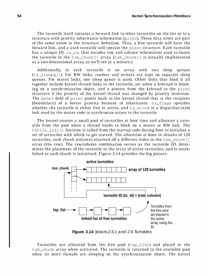
94 Kernel Synchronization Primitives
The turnstile itself contains a forward link to other turnstiles on the list or to astructure with priority inheritance information (pirec ). These data items are partof the same union in the structure definition. Thus, a free turnstile will have theforward link, and a used turnstile will contain the pirec structure. Each turnstilehas a unique ID, ts_id , that encodes row and column information used to locatethe turnstile in the tsm_chunk[] array. (tsm_chunk[] is actually implementedas a two-dimensional array, as we’ll see in a minute.)
Additionally, in each turnstile is an array with two sleep queues(ts_sleepq[] ). For RW locks, readers and writers are kept on separate sleepqueues. For mutex locks, one sleep queue is used. Other links that bind it alltogether include kernel thread links to the turnstile, set when a kthread is block-ing on a synchronization object, and a pointer from the kthread to the pirecstructure if the priority of the kernel thread was changed by priority inversion.The benef field of pirec points back to the kernel thread that is the recipient(beneficiary) of a better priority because of inheritance. ts_flags specifieswhether the turnstile is either free or active, and ts_wlock is a dispatcher-stylelock used by the mutex code to synchronize access to the turnstile.
The kernel creates a small pool of turnstiles at boot time and allocates a turn-stile from the pool when a thread needs to block on a mutex or RW lock. Thetstile_init() function is called from the startup code during boot to initialize aset of turnstiles with which to get started. The allocation is done in chunks of 128turnstiles, each chunk (column) attached off a different index in the tsm_chunk[]array (the row). The row/column combination serves as the turnstile ID, deter-mines the placement of the turnstile in the array of active turnstiles, and is estab-lished as each chunk is initialized. Figure 3.14 provides the big picture.
Turnstiles are allocated from the free pool (tsp_list ) and placed in thetsm_chunk array when activated. The turnstile is returned to the available poolwhen no more threads are sleeping on the synchronization object. The kernel
tsm_chunk array of 128 turnstiles
tsp_list
linked list of free turnstiles
active turnstiles
turnstile ID (ts_id) = (row, column)
Turnstiles fromthe free poolare placed inthe activearray, using theID.
Figure 3.14 Solaris 2.5.1 and 2.6 Turnstiles
Turnstiles and Priority Inheritance 95
attempts to maintain a pool of turnstiles that keeps pace with the number of ker-nel threads on the system by looking at the turnstile pool every time the internalthread_create() function is called to create a new kernel thread. If the numberof kernel threads is greater than the number of turnstiles in the pool when a ker-nel thread is created, then the code dynamically allocates another chunk of turn-stiles. This is somewhat different from the Solaris 7 implementation, where aturnstile is created and linked to every kernel thread when the kernel thread iscreated. Conceptually, it addresses the same problem of having a sufficient num-ber of turnstiles available at all times.
The turnstile functions called by the mutex and RW lock code to put a thread tosleep work as follows. The mutex and RW locks each contain a reference to a turn-stile for the synchronization object, which we’ll refer to generically as waiters inthis discussion.
• If the waiters field in the lock is 0 (no waiters), then a turnstile is allocatedfrom the pool by tstile_alloc() , which simply allocates a turnstile off thetsp_list pointer (the free pool link) after setting the pool lock, tsp_lock .
• The active counter is incremented, the pool lock is released, and the pirecstructure associated with the new turnstile is cleared.
• The waiters field in the lock is set to the turnstile ID of the turnstile justallocated, and the turnstile’s ts_sobj_priv_data (turnstile synchroniza-tion object private data) field is set to point to the address of the lock struc-ture.
• If threads (at least one other) are already waiting for the mutex, then a turn-stile already exists, so the address of the turnstile that has already been allo-cated for the mutex is retrieved with the tstile_pointer() function, whichuses the turnstile ID in the waiters field of the lock to locate the turnstile inthe tsm_chunk array.
With a turnstile for the lock now ready, we can proceed with changing the threadstate to sleep and setting up the sleep queue associated with the turnstile.
• The kernel t_block() function is called and invokes the CL_SLEEP macro.• Scheduling-class-specific functions are invoked by macros that resolve to the
proper function, based on the scheduling class of the kernel thread. In thecase of a timeshare or interactive class thread, the ts_sleep() function iscalled to set the thread’s priority to a SYSpriority (a priority boost for when itwakes up—it will run before other timeshare and interactive class threads)and to set the thread state to TS_SLEEP.
• The kernel thread’s t_wchan field (wait channel) is set to the address of thelock the thread is waiting for, and the thread’s t_sobj_ops pointer is set tothe lock’s synchronization object operations vector. (See “SynchronizationObject Operations Vector” on page 70.)
• Finally, the threads t_ts field is set to the address of the turnstile, and thethread is inserted on the turnstile’s sleep queue.

96 Kernel Synchronization Primitives
The generic kernel sleep queue functions are invoked indirectly through mac-ros defined in the turnstile header file; for example, insertion of the thread ona sleep queue is done through the TSTILE_INSERT macro, which calls thekernel sleepq_insert() function.
• When sleepq_insert() completes, the kernel thread resides in the sleepqueue associated with the turnstile. A kernel thread can be blocked only onone, and no more than one, sychronization object at any time, so t_ts willeither be a NULL pointer or a pointer to one turnstile.
All that remains to be done is the priority inheritance check to determine if thethread holding the lock is at a lower (worse) priority than the thread requestingthe lock (the one that was just placed on a turnstile sleep queue).
• The kernel pi_willto() function is called to check the priority of the lockowner against the thread waiting.
• If the owner priority is greater than the waiter priority, we do not have a priorityinversion condition and the code just bails out.
• If the waiter priority is greater (a better priority) than the owner, we do have a pri-ority inversion condition; then, the priority of the lock owner is set to the priorityof the waiter.
• The t_epri field of the kernel thread is used for inherited priorities. Anon-null value in t_epri results in the inherited priority of the thread beingused the next time the lock owner’s priority is adjusted (when we enter thedispatcher through an explicit call to the swtch() function).
At this point, the turnstile has been set, with the waiting thread on the turnstile’ssleep queue, and a potential priority inversion problem has been checked for a pri-ority inheritance if needed.
• The kernel now enters the dispatcher through the swtch() function toresume scheduling threads.
• When a thread has finished working in the protected data region, it calls theappropriate lock exit routine (mutex_exit() or rw_exit() ) to free the lock,which in turn triggers the wakeup mechanism if threads are waiting for thelock.
• The release function checks the waiters field maintained in the synchroni-zation object.As with mutex and RW locks, the decision on which thread to wake up orwhether to wake all the waiting threads varies depending on the synchroni-zation object and the version of the Solaris kernel. We examined what hap-pens in each circumstance in the sections on mutex and RW locks.
The turnstile support functions used in Solaris 2.5.1 are t_release() for wakinga single thread and t_release_all() for waking all the threads. Solaris 2.6 usesmacros instead (e.g., TSTILE_WAKEONE), which have the same net effect. That is,the macros result in entering the generic sleep queue code, which has a corre-

Dispatcher Locks 97
sponding function for removing either one thread or all threads from a sleep queue(e.g., sleepq_wakeone() to wake one thread). Prior to issuing the wakeup, thelock code checks for priority inheritance. If the thread releasing the lock was a ben-eficiary of priority inheritance, then the pi_waive() function is called to changethe thread’s priority back to what it was before the inheritance.
The wakeup code unlinks the kernel thread (or threads) from the sleep queueand calls the scheduling-class-specific wakeup code (e.g., ts_wakeup() for time-share and interactive threads). If the thread has been given a SYS class priority(kernel mode priority), the thread is immediately placed on a dispatch queue in theclass wakeup function. If not, the thread’s global priority is recalculated before thethread is placed on a dispatch queue.
3.8 Dispatcher Locks
The kernel defines lock types that are specific to the kernel dispatcher (threadsscheduler), referred to as dispatcher locks. Two lock types are implemented for thedispatcher: simple spin locks and locks that raise the interrupt priority level of theprocessor. These locks are acquired and released by interfaces specific to the locktypes (not the previously discussed mutex interfaces). They are also used in a fewother areas of the kernel where the requirements for locking warrant the seman-tics and behavior defined by these locks. We first discuss why the second type oflock, a lock that blocks interrupts, is necessary and then discuss the implementa-tion.
When an interrupt is generated and sent to a processor, the processor must stopwhat it’s doing and execute an interrupt handler. For low-level interrupts (belowlevel 10 on SPARC systems), interrupts are handled on an interrupt thread. What-ever thread was executing when the interrupt is received is pinned, such that theinterrupt thread can borrow the running thread’s LWP; the interrupt thread exe-cutes using its own stack. When the handler is done, the interrupted kernel threadis unpinned and can resume execution. Once executing the interrupt handler, it ispossible that the interrupt code could block. If this happens, the dispatcherswtch() function is entered, to determine whether the thread is running as apinned (interrupt) thread. If it is, the pinned thread is unpinned and selected toresume execution. The kernel implements a resume function,resume_from_intr() , specifically to deal with the special case of restarting apinned thread when an interrupt thread blocks.
High-level interrupts (interrupts above level 10 on SPARC), on the other hand,are not handled on an interrupt thread. When an interrupt above level 10 isreceived by a processor, the processor is vectored directly into a handler and exe-cutes in the context of the thread that was running when the interrupt arrived.The key point here is that low-level interrupts may require a thread contextswitch; high-level interrupts do not.

98 Kernel Synchronization Primitives
A processor will execute at any one of the architecturally defined interrupt lev-els, and different processors on a multiprocessor system can be executing at differ-ent interrupt levels. The interrupt level at which a processor is executing isestablished by the level set in an internal hardware register. On UltraSPARC pro-cessors, the PIL field of the PSTATEregister reflects the interrupt level at whichthe processor is running. The kernel code writes a new PIL value to the hardwarePSTATE register to change the interrupt level of the processor. A processor willonly receive interrupts that are at a level higher than the level at which it is cur-rently executing. For example, a processor running at PIL 4 will take an interruptat PIL 5 or higher, but not interrupts at levels 1, 2, or 3. Thus, processors are ableto mask or block interrupts by setting the PIL to the appropriate level, dependingon what level of interrupts the processor needs to block.
The kernel dispatcher (threads scheduler) does the selection and context switch-ing of threads and manipulates the dispatch queues. Hence, a protection mecha-nism is required to prevent the dispatcher from being interrupted while doingqueue insertion or removal. Since low-level interrupts may require a contextswitch, allowing a processor executing in the dispatcher code to take an interruptand switch to an interrupt handler could result in corruption of the thread stateand queue pointers. For this reason, a type of dispatcher lock is implemented. Thelock code is called from various places by the dispatcher that not only acquires aspin lock (typically, a lock protecting the dispatch queue) but that also raises thePIL to 10, effectively blocking low-level interrupts. Only high-level interrupts,which are not permitted to require or cause a context switch, are fielded.
The implementation does not define two different lock structures for spin locksand locks that block interrupts. In both cases, the lock definition is a 1-byte dataitem. The code either acquires a basic spin lock or acquires a lock and raises thePIL, based on which interface it calls. A simple lock_set() interface is called toacquire a dispatcher spin lock. The code is implemented in assembly language andfollows the fundamental algorithm for spin locks.
If the lock is held when an attempt to get the lock is made, a spin loop is used,checking the lock and attempting to acquire it in each pass through the loop. Forinterrupt protection, the lock_set_spl() interface is called. lock_set_spl()raises the PIL of the calling processor to 10 and essentially uses the same spinalgorithm as the basic spin lock. The PIL of the processor remains elevated untilthe lock is released. The lock_set_spl() code saves the current PIL of the call-ing process so that when the lock is released, the calling process can be restored tothe level at which it was executing.
Areas of the kernel that use dispatcher locks, aside from the dispatcher itself,are the other kernel synchronization primitives: that is, mutex locks, reader/writerlocks, turnstiles, and semaphores. The synchronization primitive kernel modulesuse dispatcher locks when manipulating threads on turnstiles or sleep queues orwhen protecting access to a particular data item in a lock structure.
As the Solaris releases evolve, improvements are continually made, and the useof dispatcher locks has been reduced with each successive release. For example,
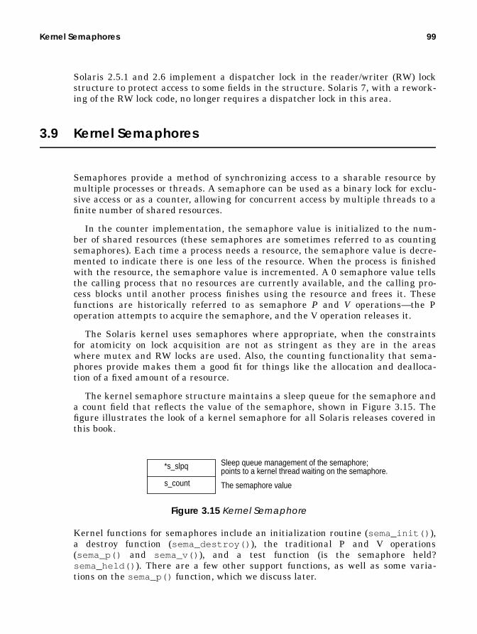
Kernel Semaphores 99
Solaris 2.5.1 and 2.6 implement a dispatcher lock in the reader/writer (RW) lockstructure to protect access to some fields in the structure. Solaris 7, with a rework-ing of the RW lock code, no longer requires a dispatcher lock in this area.
3.9 Kernel Semaphores
Semaphores provide a method of synchronizing access to a sharable resource bymultiple processes or threads. A semaphore can be used as a binary lock for exclu-sive access or as a counter, allowing for concurrent access by multiple threads to afinite number of shared resources.
In the counter implementation, the semaphore value is initialized to the num-ber of shared resources (these semaphores are sometimes referred to as countingsemaphores). Each time a process needs a resource, the semaphore value is decre-mented to indicate there is one less of the resource. When the process is finishedwith the resource, the semaphore value is incremented. A 0 semaphore value tellsthe calling process that no resources are currently available, and the calling pro-cess blocks until another process finishes using the resource and frees it. Thesefunctions are historically referred to as semaphore P and V operations—the Poperation attempts to acquire the semaphore, and the V operation releases it.
The Solaris kernel uses semaphores where appropriate, when the constraintsfor atomicity on lock acquisition are not as stringent as they are in the areaswhere mutex and RW locks are used. Also, the counting functionality that sema-phores provide makes them a good fit for things like the allocation and dealloca-tion of a fixed amount of a resource.
The kernel semaphore structure maintains a sleep queue for the semaphore anda count field that reflects the value of the semaphore, shown in Figure 3.15. Thefigure illustrates the look of a kernel semaphore for all Solaris releases covered inthis book.
Figure 3.15 Kernel Semaphore
Kernel functions for semaphores include an initialization routine (sema_init() ),a destroy function (sema_destroy() ), the traditional P and V operations(sema_p() and sema_v() ), and a test function (is the semaphore held?sema_held() ). There are a few other support functions, as well as some varia-tions on the sema_p() function, which we discuss later.
*s_slpq
s_count
Sleep queue management of the semaphore;points to a kernel thread waiting on the semaphore.
The semaphore value

100 Kernel Synchronization Primitives
The init function simply sets the count value in the semaphore, based on thevalue passed as an argument to the sema_init() routine. The s_slpq pointer isset to NULL, and the semaphore is initialized. The sema_destroy() function isused when the semaphore is an integral part of a resource that is dynamically cre-ated and destroyed as the resource gets used and subsequently released. For exam-ple, the bio (block I/O) subsystem in the kernel, which manages buf structures forpage I/O support through the file system, uses semaphores on a per-buf structurebasis. Each buffer has two semaphores, which are initialized when a buffer is allo-cated by sema_init() . Once the I/O is completed and the buffer is released,sema_destroy() is called as part of the buffer release code. (sema_destroy()just nulls the s_slpq pointer.)
Kernel threads that must access a resource controlled by a semphore call thesema_p() function, which requires that the semaphore count value be greaterthan 0 in order to return success. If the count is 0, then the semaphore is not avail-able and the calling thread must block. If the count is greater than 0, then thecount is decremented in the semaphore and the code returns to the caller. Other-wise, a sleep queue is located from the systemwide array of sleep queues, thethread state is changed to sleep, and the thread is placed on the sleep queue. Notethat turnstiles are not used for semaphores—turnstiles are an implementation ofsleep queues specifically for mutex and RW locks. Kernel threads blocked on any-thing other than mutexes and RW locks are placed on sleep queues.
Sleep queues are discussed in more detail in Chapter 6, “The Solaris Dis-patcher.” Briefly though, sleep queues are organized as a linked list of kernelthreads, and each linked list is rooted in an array referenced through asleepq_head kernel pointer. Some changes were made in Solaris 7 to facilitatefaster sleep queue operations: insertion, removal, and queue traversal. In Solarisreleases prior to Solaris 7, an entry in the sleepq_head array begins a linked listof kernel threads waiting on the same object. The list is singly linked by the ker-nel threads t_link pointer. In Solaris 7, several additional pointers were added tothe kernel thread to support a doubly linked sublist of threads at the same prior-ity. Figure 3.16 illustrates how sleep queues are organized.

Kernel Semaphores 101
Figure 3.16 Sleep Queues in Solaris 2.5.1, 2.6, and 7
In all pre- and post-Solaris 7 implementations, a hashing function indexes thesleepq_head array, hashing on the address of the object. In the pre-Solaris 7implementation, kernel threads are inserted on the list in descending order basedon their priority. In Solaris 7, the singly linked list that establishes the beginningof the doubly linked sublists of kthreads at the same priority is also in ascendingorder based on priority. The sublist is implemented with a t_priforw (forwardpointer) and t_priback (previous pointer) in the kernel thread. Also, a t_sleepqpointer added in Solaris 7 points back to the array entry in sleepq_head , identi-fying which sleep queue the thread is on and providing a quick method to deter-mine if a thread is on a sleep queue at all; if the threads t_sleepq pointer isNULL, then the thread is not on a sleep queue).
Inside the sema_p() function, if we have a semaphore count value of 0, thesemaphore is not available and the calling kernel thread needs to be placed on asleep queue. A sleep queue is located through a hash function into thesleep_head array, which hashes on the address of the object the thread is block-ing, in this case, the address of the semaphore. The code also grabs the sleep queuelock, sq_lock (see Figure 3.16) to block any further inserts or removals from thesleep queue until the insertion of the current kernel thread has been completed(that’s what locks are for!).
sq_locksq_firstsq_locksq_firstsq_locksq_firstsq_locksq_first
t_link
sleepq_head
t_link
t_link
t_linkt_link
t_link
t_link
kernel threads
Kernel threads along this link are waiting on the same object.
Sleep Queues in Solaris 2.5.1 and 2.6
sq_locksq_firstsq_locksq_firstsq_locksq_firstsq_locksq_first
Sleep Queues in Solaris 7
t_linkt_priforwt_pribackt_sleepq
t_linkt_priforwt_pribackt_sleepq
t_linkt_priforwt_pribackt_sleepq
t_linkt_priforwt_pribackt_sleepq
t_linkt_priforwt_pribackt_sleepq
sleepq_head
Kernel threads alignedvertically are of the samepriority. Threads alignedhorizontally are waitingon the same object.

102 Kernel Synchronization Primitives
The scheduling-class-specific sleep function is called to set the thread wakeuppriority and to change the thread state from ONPROC(running on a processor) toSLEEP. The kernel thread’s t_wchan (wait channel) pointer is set to the address ofthe semaphore it’s blocking on, and the thread’s t_sobj_ops pointer is set to ref-erence the sema_sobj_ops structure. The thread is now in a sleep state on asleep queue.
A semaphore is released by the sema_v() function, which has the exact oppo-site effect of sema_p() and behaves very much like the lock release functionswe’ve examined up to this point. The semaphore value is incremented, and if anythreads are sleeping on the semaphore, the one that has been sitting on the sleepqueue longest will be woken up. Semaphore wakeups always involve waking onewaiter at a time.
Semaphores are used in relatively few areas of the operating system: the bufferI/O (bio ) module, the dynamically loadable kernel module code, and a couple ofdevice drivers.

4
KERNEL BOOTSTRAPAND INITIALIZATION
In the previous chapters, we provided a description of the Solaris kernel and anoverview of the key features and facilities of the operating system. We emphasizedthe modular and dynamic nature of the kernel because the Solaris kernel does notoriginate on disk as a single, monolithic binary object. Rather, the kernel is con-structed in memory, during system bootstrap, as major operating system compo-nents are loaded.
Kernel objects load both at boot time and while the system is running. In thischapter, we take a look at the directory hierarchy that stores binary kernel objects.We then discuss the kernel bootstrap and initialization process, the dynamic mod-ule loading facility, and the kernel runtime linker.
4.1 Kernel Directory Hierarchy
The binary object modules that make up the Solaris kernel exist in a well-defineddirectory name space in the root and usr file systems. The system directorynames are described in Table 4-1.
103

104 Kernel Bootstrap and Initialization
The core modules that make up the minimum required for a usable system aresplit across multiple directories. All kernel modules will be in one of three possiblecategories that determine their placement in the directory hierarchy: platform andhardware independent, platform dependent, or hardware class dependent. The/kernel directory tree contains operating system modules that are platform inde-pendent, including the genunix executable object that is loaded initially at boottime.
The two remaining directory trees are categorized as hardware-class dependentand platform dependent. The hardware-class is derived from the processor type, inconjunction with the processor-to-memory bus architecture. UltraSPARC-basedsystems have a sun4u hardware class; all such systems use the Ultra Port Archi-tecture (UPA) as the primary processor interconnect. Hardware classes sun4m andsun4d are systems based on the SuperSPARC (SPARC Version 8), which uses theMbus (sun4m) interconnect on smaller systems and the XDBus on the largerserver systems. You can determine the hardware-class of a system by using theuname(1) command with the -m option.
The platform category is the specific machine type: the type of system, precededby a SUNW for Sun-based platforms. Examples include SUNW,Ultra-2 andSUNW,Ultra Enterprise-10000. Kernel modules that deal specifically with “box”dependencies, such as environmental controls and interconnect-specific support,
Table 4-1 System Directories
DirectoryName
Description
root (/ ) Beginning of the system directory name space/kernel Subdirectory tree with platform-independent loadable
kernel modules/platform Subdirectory tree with platform-dependent loadable
kernel modulesThe following directories are not subdirectories under root (/). Rather,they are directory names that hold specific types of kernel objects andexist as subdirectories under several top-level directories, such as /ker-nel , /platform/ <arch >) and /usr/kernel . Refer to Figure 4.1.sparcv9 Solaris 7 and later. The directory name space uses the
sparcv9 subdirectory name to store all 64-bit kernelobjects
drv Device driversexec Executable object file routinesfs File system modulesmisc Miscellaneous modulessched Scheduling classesstrmod STREAMS module supportsys System calls

Kernel Directory Hierarchy 105
reside in the directory tree beginning with /platform/< platform-name >. Fig-ure 4.1 shows the directory hierarchy.
Figure 4.1 Core Kernel Directory Hierarchy
For illustration, we use a specific platform (SUNW,UltraEnterprise) and hardwareclass (sun4u, which is all UltraSPARC processors) in the example directory tree inFigure 4.1. The modules in these directories make up all the components that areloaded at boot time and are required for a fully functional system.
Other loadable kernel modules are located under the /usr directory tree, whichalso contains a kernel (/usr/kernel ) and platform (/usr/platform ) set of sub-directories. The modules under these directories are kernel modules that areloaded as needed: either on demand, as a result of a user or application processrequesting a service that requires the loading of one of the modules, or manuallywith the modload (1M) command. For example, the kernel exec support for execut-ing code written in the Java programming language is in /usr/kernel/exec andhas the file name javaexec . This module is loaded by the kernel the first time aJava program is started on the system. Note that you can instruct the system toload optional modules at boot time by using the forceload directive in the/etc/system kernel configuration file.
The full path names of the core executable files that form the nucleus of the ker-nel are listed below.
/kernel /platform
genunix
drv exec fs misc sched strmod sys
<hardware-class><platform name>
sun4u SUNW,Ultra Enterprise
kernelcprbootcprbooterkadbufsboot
unixgenunixcpu drv misc strmod
kernel
misc
platmod
root
sparcv9
sparcv9
unixgenunix
sparcv9sparcv9
platmod
hardware-independentkernel objects
hardware-dependentkernel objects

106 Kernel Bootstrap and Initialization
• /platform/<arch>/kernel/unix — The platform-dependent component ofthe core kernel.
• /platform/sun4u/kernel/genunix — A genunix binary optimized forUltraSPARC, but independent of the system (box) type. Only Ultra-SPARC-based systems load this particular binary.
• /kernel/genunix — Platform-independent (generic) core kernel code. Onlynon-UltraSPARC-based systems load this file.
Note that only one genunix binary gets loaded at boot time: either the Ultra-SPARC version on sun4u hardware or the /kernel/genunix image on all otherSPARC systems. These objects contain all the low-level kernel services and otherfacilities that need to be memory resident to properly initialize the system andsupport the dynamic load environment.
Included within the unix and genunix images are the memory managementroutines, callback and callout facilities, clock and timer support, kernel memoryallocator, module load facility, the kernel runtime linker, synchronization primi-tives, kernel thread and lightweight process code, and device driver interfaces.
The remaining bits load as modules from the directories described in Table 4-1on page 104. For a listing of the modules currently loaded in a running system, usethe modinfo (1M) command.
The sample output above is a partial listing from a running Solaris 7 system. mod-info (1M) provides the name of the kernel object and a brief description. Each ker-nel module has a unique identifier, shown in the Id column. The kernel virtualaddress (Loadaddr ) and size of the module are also displayed, along with mod-ule-specific data in the Info column.
# modinfo Id Loadaddr Size Info Rev Module Name 4 f5b28000 3b30 1 1 specfs (filesystem for specfs) 6 f5b2bb30 2bc8 1 1 TS (time sharing sched class) 7 f5b2e6f8 4a4 - 1 TS_DPTBL (Time sharing dispatch table) 8 f5c0e000 23548 2 1 ufs (filesystem for ufs) 11 f5b63d08 b30 1 1 rootnex (sun4m root nexus) 13 f5b649c0 530 62 1 dma (Direct Memory Access driver) 14 f5b64ef0 aeb 59 1 sbus (SBus nexus driver) 16 f5b67388 14e8 12 1 sad (Streams Administrative driver’s) 44 f5bc2d58 1eed 0 1 elfexec (exec module for elf) 57 f5eb3000 bb40 8 1 sockfs (filesystem for sockfs) 63 f5bd7da0 3586 201 1 doorfs (doors) 64 f5bdb328 c3c 12 1 fdfs (filesystem for fd) 65 f5f18000 f05 38 1 openeepr (OPENPROM/NVRAM Driver) 72 f5bdbf68 6c6 90 1 kstat (kernel statistics driver) 73 f6003000 d3ef 11 1 tmpfs (filesystem for tmpfs) 91 f625f000 1ce0 52 1 shmsys (System V shared memory) 92 f5bdefa0 268 - 1 ipc (common ipc code) 93 f625bac0 1512 - 1 bootdev (bootdev misc module)106 f6a19000 587a 40 1 le (Lance Ethernet Driver v1.120)107 f5ff1aa8 4d1 78 1 ledma (le dma driver)

Kernel Bootstrap and Initialization 107
It is from the binary kernel modules that reside within these directories thatthe in-memory Solaris kernel is constructed.
4.2 Kernel Bootstrap and Initialization
The boot process loads the binary kernel objects that make up the Solaris kernelfrom a bootable system disk into physical memory, initializes the kernel struc-tures, sets system tuneable parameters, starts system processes (daemons), andbrings the system to a known, usable state. The basic steps involved in booting canbe summarized as follows.
1. The boot (1M) command reads and loads the bootblock into memory.2. The bootblock locates and loads the secondary boot program, ufsboot , into
memory and passes control to it.3. ufsboot locates and loads the core kernel images and the required kernel
runtime linker into memory and passes control to the loaded kernel.4. The core kernel locates and loads mandatory kernel modules from the root
disk directory tree and executes the main startup code.5. The kernel startup code executes, creating and initializing kernel structures,
resources, and software components.6. The system executes shell scripts from system directories, bringing the
system up to the init state specified in the /etc/inittab file.
The preliminary steps shown above are based on a local disk boot. A network bootuses a different secondary boot program: inetboot instead of ufsboot . Our con-tinuing discussion is based on a local disk boot.
4.2.1 Loading the Bootblock
The initial stage of the boot process requires support from system firmware, typi-cally loaded in a PROM, such that a bootable device can be addressed and thatsome minimal I/O functionality exists for the reading of a primary bootblock.
Sun SPARC-based systems implement system firmware, known as the Open-Boot PROM (OBP), in the Forth programming language. The OBP firmware pro-vides Power-On Self-Test (POST) functionality for hardware integrity testing,provides a Non-Volatile RAM (NVRAM) space for setting system parameters (e.g.,the default boot device), builds a device tree that reflects the hardware configura-tion of the system, and provides bootstrap support. Intel-based systems useBIOS-based firmware that provides similar functionality. Our coverage herefocuses on SPARC-based systems, although much of the initialization process ishardware independent once the secondary boot phase has completed and the ker-nel is loaded.

108 Kernel Bootstrap and Initialization
On a system that has completed its POST tests, the boot process is initiatedeither with an explicit boot (1M) command at the OBP prompt or, if theauto-boot? NVRAM variable is set to true , initiating an automatic boot whenthe system is powered up. The boot (1M) command supports several options,including specifying a boot device and bootfile on the command line (somethingother than the default), flagging a boot into the kernel debugger (kadb ), runningthe boot in a more verbose mode for more output, etc. Refer to the manual page onboot (1M) for specifics.
On SPARC systems using the default Unix file system (UFS) for the root filesystem (a.k.a. the system disk), the bootblock is located on physical disk sectors 1–15, as shown in Figure 4.2. The blocks are labeled as sectors 0 through 16 to dis-tinguish them from file system blocks. Physical sectors on a disk are 512 bytes insize, whereas file system blocks are typically a grouping of some number of physi-cal disk sectors (16 in UFS, for a default file system block size of 8 Kbytes).
Figure 4.2 Bootblock on a UFS-Based System Disk
Sector 0, the Virtual Table Of Contents (VTOC), contains the disk partition infor-mation: the starting and ending block numbers for each of eight possible on-diskpartitions. Sector 16 is where a UFS puts the primary superblock (file systemmetadata).
The Solaris environment provides an installboot (1M) command, which addsor restores a bootblock to a system partition. The bootblock code is maintained inthe /usr/platform/< arch >/lib/fs/ufs/bootblk file. The install-boot (1M) utility just uses dd(1) to copy this file to the specified disk partition. Thesize of the bootblock is constrained (it cannot be larger than 7,680 bytes—15 sec-tors at 512 bytes each), so it is the bare minimum amount of code required to reada directory in a UFS, locate a file, and load it into memory.
4.2.2 Loading ufsboot
The secondary bootfile name, ufsboot , is hardcoded into the bootblock code for aUFS boot; the full path name for ufsboot is /platform/< arch >/ufsboot . (Inearly Solaris versions, up to and including Solaris 2.4, ufsboot was located in theroot directory, /ufsboot .)
Note that the references to <arch > indicate that for this field in the path name,you should substitute the output from uname -m, which displays the hardwareclass of the system (e.g., sun4u, sun4m, x86, etc.).
ufs bootblock
VTOC
sector-0 sector-1 sector-15 sector-16
begin UFSsuperblock
. . . . . . .

Kernel Bootstrap and Initialization 109
4.2.3 Locating Core Kernel Images and Linker
ufsboot , once loaded, locates the kernel image, unix , and the required runtimelinker, krtld . The full path name of the first kernel binary loaded by ufsboot is/platform/< arch >/kernel/unix (e.g., /platform/sun4u/kernel/unix on UltraSPARC-based systems). The unix file is an Executable and Link-ing Format (ELF) binary file, the industry-standard file format for executablebinary files on Unix systems. In an ELF file, specific bits of header informationneed to be examined to determine things like the execution dependencies. ufs-boot knows about ELF files—how to interpret the header information and how toextract the dependencies. Based on information in the unix ELF headers, ufs-boot loads the required kernel runtime linker, /kernel/misc/krtld .
4.2.4 Loading Kernel Modules
Control is passed to krtld , which notes dependencies on additional binary objectfiles. Below is the partial output of the dump(1) command on the /plat-form/sun4u/kernel/unix file, illustrating the dependency listing of the unixbinary.
The dump(1M) flags shown dump the.dynamic section of an ELF object file. Notlisted is the PT_INTERP entry, which in this case is misc/krtld .
First is the genunix binary, located in /kernel/genunix for all non-UltraS-PARC-based platforms, or /platform/sun4u/kernel/genunix for all UltraS-PARC (sun4u) platforms. The remaining dependencies are/platform/< arch >/kernel/misc/platmod and /platform/< arch >/ker-nel/cpu/$CPU , which are platform- and processor-specific binaries that are partof the core kernel. The $CPUsymbol is set to the specific processor type by the OBPfirmware and expands properly when krtld resolves the symbol. krtld uses amodule search path variable, which is similar to the traditional Unix shell PATHvariable; the module search path specifies the directory names to be searched fordynamically loadable kernel modules. The module search path variable is set bythe OBP firmware and differs slightly across different hardware platforms (thesearch path can be specified by being booted with boot -a ). As krtld encounters
# pwd/platform/sun4u/kernel# /usr/ccs/bin/dump -Lv unix
unix:
**** DYNAMIC SECTION INFORMATION ****.dynamic:[INDEX] Tag Value[1] NEEDED genunix[2] NEEDED misc/platmod[3] NEEDED cpu/$CPU[4] HASH 0x114...

110 Kernel Bootstrap and Initialization
binary object dependencies, it searches directories specified in the module searchpath.
Figure 4.3 illustrates the boot flow up to this point, using the sun4u (Ultra-SPARC) directory hierarchy for the example.
Figure 4.3 Boot Process
4.2.5 Creating Kernel Structures, Resources, andComponents
With all the core binary objects (unix , krtld , genunix , platmod , and the $CPUmodule) loaded into memory and linked, krtld passes control to unix , which isloaded near the top of physical memory space, to take over execution. The Solariskernel is now running, the Memory Management Unit (MMU) is enabled (the codeis generating virtual addresses and working in virtual address space), and the first16 megabytes of memory are mapped. unix does some low-level setup of processorregisters, begins hand-crafting kernel thread 0, and calls an architecture-specificstartup function, mlsetup() . mlsetup() completes the initialization of kernelthread 0 and LWP 0, builds the first process (p0), and begins mapping systemdevices according to device information in the OBP space.
The EEPROM on SPARC systems, which holds the OBP code, is one of the earlydevices mapped. That is, the eeprom occupies a part of the system’s physicaladdress space, much like a physical device. A kernel software layer is initialized,very similar to a device driver, allowing other areas of the kernel to call into thePROM. Calls into the PROM are required during the boot process for a variety ofreasons, such as the retrieval of hardware and version information.
With the mlsetup() work done, the kernel main() function is entered, whichis where the code begins a sequence of function calls into the higher-level areas ofthe kernel to continue the initialization process. The main() function is part of thekernel hardware-independent code. It immediately calls into hardware-specific
OBP
PhysicalMemory(RAM)
system (root) disk
platformkernelsun4u
kernel ufsboot
unixgenunix
misc cpu drv strmod
genunix
drv exec fs misc sched strmod sys
bootblock
boot(1M)
bootblock loads ufsboot
ufsboot loadsunix, krtld.krtld loadsgenunix, cpuand platformmodules.

Kernel Bootstrap and Initialization 111
routines for specific initialization steps, then returns to the common code to com-plete the boot process.
The platform-specific startup() function does some preliminary memory ini-tialization: determining available physical memory after the core kernel is loaded,setting up of the kernel address space symbols, and allocating memory page struc-ture. The kernel memory allocation (KVM) subsystem and the kernel kstat (ker-nel statisitics) framework. are initialized Once these steps are completed, theoperating system banner is displayed on the console;
Additional platform-specific checking is done on processor types, firmware ver-sions, etc., and the kernel mod_read_system_file() function is called to readthe /etc/system file and populate internal data structures with the parametersand values set in /etc/system .
The kernel creates a linked list of sysparam data structures, such that each entryon the /etc/system file has a corresponding data structure in the list. The sys-param structure is defined in /usr/include/sys/sysconf.h , and is shownbelow.
The fields in the sysparam structure are generally self-explanatory. Space isdefined for parameter-specific information, the parameter type (e.g., a module loadentry or an entry to set a value), and the necessary pointer to maintain the linkedlist. The mod_read_sys_file() code walks through each line on /etc/system ,doing the necessary parsing to determine the entry types and setting the appropri-ate values in the sysparam structure that corresponds to the line entry in/etc/system . When mod_read_sys_file() is finished, a linked list of popu-lated sysparam structures is established in kernel memory.
Before mod_read_sys_file() returns, the code sets the maxusers value. Themaxusers parameter is calculated on the basis of the amount of physical memory
SunOS Release 5.7 Version Generic 64-bit [UNIX(R) System V Release 4.0]Copyright (c) 1983-1998, Sun Microsystems, Inc.
/* * For each entry in /etc/system a sysparam record is created. */struct sysparam { struct sysparam *sys_next; /* pointer to next */ int sys_type; /* type of record */ int sys_op; /* operation */ char *sys_modnam; /* module name (null if param in kernel) */ char *sys_ptr; /* string pointer to device, etc. */ u_longlong_t sys_info; /* additional information */ char *sys_config; /* configuration data */ int sys_len; /* len of config data */ u_long *addrp; /* pointer to valloced config addresses */};
Header File <sys/sysconf.h>

112 Kernel Bootstrap and Initialization
installed on the system, where maxusers equals the number of megabytes ofRAM, to a maximum value of 1024 (which equates to 1 gigabyte of RAM—on sys-tems with greater than 1 gigabyte of physical memory, maxusers will be 1024). Ifmaxusers is set in /etc/system , that value is used, up to a maximum value of2048; any /etc/system maxusers value larger than 2048 results in maxusersgetting set to 2048. Once maxusers is established, the startup code sets other ker-nel limits, based on maxusers in the kernel param_calc() function.
• maxpid — Maximum process ID value. If pidmax is set in /etc/system , thepidmax value will be tested against a minimum reserved_procs value (5in Solaris 2.5.1, 2.6, and 7) and a maximum value (30,000 in all threereleases). If pidmax is less than reserved_procs or greater than 30,000, itis set to 30,000. Otherwise, the user-defined value is set.
• max_nprocs — Maximum number of processes, systemwide, set as (10 +16 * maxusers) .
• maxuprc — Maximum processes per non-root user, set as (max_nprocs -reservered_procs) . reserved_procs has a default value of 5.
• ufs_ninode and ncsize — High limits for the UFS inode cache and direc-tory name cache. (See “The Directory Name Lookup Cache (DNLC)” onpage 568.) Both of these caches are set to the same value, (4 *(max_nprocs + maxusers) + 320) .
• ndquot — The number of UFS disk quota structures, systemwide, set as((maxusers * 40) / 4) + max_nprocs) .
As you can see, maxusers is not really the maximum number of users the systemwill support. It’s simply a parameter that can be set to drive the number of sev-eral configurable kernel resources that indirectly affect the load or volume of usersthe system can handle. Many things factor in to the user load capabilities of thesystem, not the least of which are what constitutes a user, what a user does, andhow a user connects to the system.
Other kernel parameters that are related to the STREAMS subsystem and mis-cellaneous areas of the system are also set at this time. These parameters usehard-coded default values that are not driven by the maxusers parameter unless avalue has been set in /etc/system .
• nstrpush — Number of STREAMS modules that can be contained (pushed)on a single STREAM; set to 9.
• strmsgsz — Maximum size of a STREAMS message; set to 64 Kbytes.
• strctlsz — Maximum size of a STREAMS control message.
• ngroups_max — Maximum number of groups a user can belong to; set to 16.
• rstchown — A boolean that forces POSIX chown (1) behavior, where a pro-cess must have an effective UID of 0 (root) to change file ownership; set to 1(true) by default.
Kernel Bootstrap and Initialization 113
• hz , hires_hz , hires_tick — Clock frequency controls. hz is set to 100,hires_hz to 1000, and hires_tick to 0. hz and hires_hz should not bealtered. You can set hires_tick to 1 in /etc/system . Doing so results inan hz value of 1000, causing the system clock to generate a clock interrupt1000 times a second (every millisecond) versus the default of 100 times a sec-ond (every 10 milliseconds).
• autoup — Age in seconds of a dirty page before fsflush will write it to disk;set to 30.
• rlimits — Per-process resource limits. Default values are set. Per-processfile descriptor limits can be set through /etc/system , with rlim_fd_maxfor the maximum value and rlim_fd_cur for the current value (current cannever exceed the maximum).
For a complete listing of kernel tunable parameters, see [5]. See also Appendix A,“Kernel Tunables, Switches, and Limits”.”
Moving along with the system initialization process: The system device namespace is established in the /devices directory, based on the device tree created bythe OBP firmware. The system call table is initialized, and the kernel loads thedevice driver classes file, /etc/driver_classes . System parameters are set inthe var data structure; most of these parameters are values that we have previ-ously discussed (e.g., max_nprocs ), and others are not used in the Solaris kernel(var is a somewhat outdated SVR4 holdover). You can examine the relevant datastored in the var structure with the sysdef (1M) command or with the var func-tion in crash (1M).
Kernel module loading occurs at various points in the boot process. During theplatform-specific startup, several core modules, such as the swap, specfs , procfsand tod (time-of-day clock driver), are loaded. Other module loading occurs whena specific kernel subsystem is initialized. For example, the scheduling classes areloaded during the dispinit() function, which initializes the kernel dispatchersubsystem. These module loads (and dispinit() ) occur before the platform-spe-cific startup returns to the kernel main() function. Other loadable modules thatare platform specific are loaded a little later in the process. Examples here includemodules specific to the UltraEnterprise E3500 (E6500 servers that support envi-ronmental monitoring and specific control functions).
Additional virtual memory support is initialized (the HAT layer and segmentdrivers), the specfs and swapfs file system support modules are loaded and ini-tialized, the root, swap and dump devices are configured, any kernel modules setfor forceload in the /etc/system file are loaded, and the kernel trap table isset (traps were handled through the trap table set in the OBP up to this point).The system displays the memory values for actual, installed physical memory and

114 Kernel Bootstrap and Initialization
available memory, that is, what’s left after the kernel consumes whatever pages itrequires.
Some additional housekeeping, such as creating the interrupt threads and idlethread, is done for the boot processor, clock interrupts are enabled, and the deviceconfiguration process is completed. The code walks through the device tree, read-ing data from the dev_info structures created for each device and displaying thedevice information on the console. Several kernel initialization functions for spe-cific subsystems, such as the callout table, buffer I/O subsystem, credentials andfile cache, pseudoterminal and STREAMS support, etc., are invoked through an inittable array. Several kernel daemon threads are created, the init , pageout , andfsflush processes are created, and any additional processors (MP system) are ini-tialized.
The process creation of init , pageout , and fsflush is done by means of aninternal newproc() kernel function, which gets the process table slot and processID and does some initialization of the proc structure members. An LWP and ker-nel thread are also created from the newproc() function. The pageout andfsflush processes are actually part of the kernel and execute as kernel threadswithin the kernel’s address space. The process table entries for these processes aresimply placeholders, providing a user-visible view of process execution time (theTIME column from the ps (1) command).
The init process, also created with a call to newproc() from the kernelmain() function, is the first real user process Solaris creates. Additional work isdone by the code path entered when the initial process creation phase (new-proc() ) is completed. First and foremost, a user address space is allocated for theinit process; it does not attach to or execute in the kernel’s address space. Sec-ond, an on-disk binary file—/sbin/init —is exec’d once the process initializationis completed. The pageout and fsflush processes do not have a distinct useraddress space; instead, they attach to the kernel’s address space. Neither is anexplicit exec() function called to overlay the newly created process with a newbinary image. pageout and fsflush exist as kernel functions.
Thus, init is the first genuine user process created by the system and the lastprocess the kernel must effectively craft piece-by-piece. All further process cre-ation to get to a running system is done by forking init , and exec ’ing the appro-priate binary image from disk
4.2.6 Completing the Boot Process
The remaining phases of the boot process take place under control of the init pro-cess, which references the /etc/inittab file to determine the default init level(typically, 3) and controls the serial execution of several shell scripts in the /sbin
mem = 262144K (0x10000000)avail mem = 257785856

Kernel Bootstrap and Initialization 115
and /etc directories. The init control and script execution sequence managedthrough the inittab file is not unique to Solaris and has been used in many Sys-tem V-based Unix variants for several years. As such, it is generally well under-stood and documented in many places.
4.2.7 During the Boot Process: Creating System KernelThreads
During the boot process, the system creates several kernel threads that are notvisible outside the operating system; they cannot be seen by examination of the/proc directory hierarchy or through the ps (1) command. They show up on thesystemwide linked list of kernel threads and behave as daemon threads, called bydifferent areas of the operating system when appropriate. These threads are onlypart of the multithreaded design of the Solaris kernel, and they perform very spe-cific functions. They all execute in the SYSscheduling class and are unique in thatthey are the only kernel threads in the system that do not have a correspondingLWP. The kernel thread structure provides the necessary support for context infor-mation and a stack. Following is a list of the kernel threads created at boot time.
• thread_reaper — Cleans up exited (zombie) kernel threads placed on deathrow.
• mod_uninstall_daemon — For checkpoint/resume (CPR) support; unloadskernel modules when the system checkpoints.
• hotplug_daemon — Device hotplug support. Adds the dev_info node for anadded device to the system device tree.
• kmem_async_thread — Garbage collector thread for the kernel slab alloca-tor.
• seg_pasync_thread — Reclaims pagelocked pages that have not been refer-enced for a while.
• ksyms_update_thread — Updates the dynamic kernel symbol table,/dev/ksyms , as kernel modules are loaded.
• callout_thread — Processes the kernel callout queue by means of the clockinterrupt handler.
• cpu_pause — Per-processor; for CPU state changes.
• modload_thread — Supports dynamic loading of kernel modules.
• background — STREAMS based; services STREAMS queues. One of thesethreads is created for every CPU on a system at boot time.
• freebs — STREAMS based; manages list of free STREAMS blocks. One ofthese threads is created for every CPU on a system at boot time.

116 Kernel Bootstrap and Initialization
• qwriter_outer_thread — STREAMS based; processes outer STREAMSsyncq messages. One of these threads is created for every CPU on a systemat boot time.
All kernel threads, even those threads listed above that are part of the operatingsystem, need a process context to execute, in order to have the required softwarecontext state (for example, an address space). Kernel threads created by the oper-ating system are linked to process 0 (PID 0) for contextual information. Processcontext is discussed in detail in Chapter 5.
4.3 Kernel Module Loading and Linking
Much of the kernel architecture is layered architecture, and many of the kernel’smajor subsystems call into a common set of lower-level services. In some respects,the kernel architecture is similar to that of a client/server application, except thatthe interfaces in this case are, for the most part, private to the kernel. That is,many of the callable routines are not public interfaces available for use for generalapplication software development. The other obvious distinction is that the usersof the services, or clients, in this context, are other kernel subsystems, as opposedto application code. Exceptions to the private interface generalization are thoseinterfaces defined for device drivers and kernel STREAMS modules, which are doc-umented as the Solaris Device Driver Interface (DDI) specifications, found in sec-tion 9 of the manual pages.
The kernel module loading facility serves as a good example of one such service.Several phases are involved in dynamic module loading.
1. Load the module (a binary object file) into memory.2. Establish kernel address space mappings for module segments.3. Link the module’s segments into the kernel.4. Perform the module-type-specific install function.
The loadable module types are defined in /usr/include/sys/modctl.h ; theyare device drivers, systems calls, file systems, miscellaneous modules, streamsmodules, scheduling classes, and exec modules (exec support for executableobjects). For each of these module types, some specific kernel installation steps arerequired to complete the loading process. We will take a look at these shortly.
The steps involved in loading a module into the kernel are similar conceptuallyto what happens when a dynamically linked program is started under Solaris.That is, shared objects to which a binary is linked are dynamically loaded intomemory and linked into the process’s address space during execution. The kernelexists in memory as a large, dynamically linked executable, with essentially thesame address space segments that exist in any process running on the system:

Kernel Module Loading and Linking 117
memory mappings for text (instructions), data (initialized and uninitialized), and astack. Thus, loading a kernel module involves reading the target module intomemory and creating the address space mappings in the kernel’s address space forthe module’s text and data. This process is illustrated in Figure 4.4.
Figure 4.4 Loading a Kernel Module
The illustration in Figure 4.4 is not a precise depiction of the kernel address spaceor binary object segments but provides a conceptual view. Subsequent chaptersdescribe executable objects and address space mappings in detail.
The system loads the modules required for a functional system at boot time. Apath variable that defines the module search path (which directories to search forloadable modules) guides the boot code in locating the appropriate kernel objects.The kernel modload() function is the entry point in the code that begins the mod-ule load process. The primary data structures used in support of module loadingare the modctl (module control) structure and module structure. You can find thestructure definitions for modctl and module in /usr/include/sys/modctl.hand /usr/include/sys/kobj.h , respectively.
physical memory
kernel
kerneldata
stack
text
/kernel/<directory>/<object>
on-disk kernel object(kernel module)
executablebinary objectsegments
modload;- Read the object into memory.- Create kernel addressspace mappings.- Map the object’s segmentsinto the kernel- The new mod.ule is nowpart of “the kernel.”
kern
el a
ddre
ss s
pace

118 Kernel Bootstrap and Initialization
The kernel maintains a linked list of modctl structures for all modules in thekernel, as shown in Figure 4.5.
Figure 4.5 Module Control Structures
The kernel modules pointer marks the beginning of the doubly linked list of mod-ule control structures. Not every structure member is shown in the figure. In addi-tion to the structure links (next and previous pointers), the module identification(mod_id ) is maintained, along with links to a mod_modinfo structure andmod_linkage structure. mod_mplinks to a module structure, defined in the ker-nel object linker code (/usr/include/sys/kobj.h ), and used by the kernel run-time linker and the module load facility. Other interesting bits include characterstring pointers to the directory name, mod_filename , that holds the module andthe module file name, mod_modname.
A given kernel module may depend on the existence of other kernel modules inorder to function or may have other kernel modules depend on it. For example, theSystem V Interprocess Communication (IPC) modules for shared memory, sema-phores, and message queues all depend on the kernel ipc module to function.Such dependencies are defined in the module code and maintained in the modctlstructure by pointers in mod_requisites (other modules this module depends on)and mod_dependents (modules that depend on this one).
The kernel module loading facility is threaded. That is, when the kernel mod-load() function is called (during bootstrap or by the modload (1M) command), itcreates a kernel thread to perform the module load function. The benefit here isthat concurrent module loads are possible on multiprocessor systems and so pro-vide faster system boot and initialization. Once the kernel thread is created, thefollowing series of events is executed to complete the loading and linking of themodule.
1. Create and allocate a modctl structure. First, search the linked list ofmodctl structures, looking for a match to the module name (mod_modname).If a match is found, return address of existing structure; otherwise, create anew one. Add a new modctl structure to the linked list.
2. Enter the kernel runtime linker, krtld , to create address space segments
modules mod_nextmod_prevmod_idmod_mpmod_modinfomod_linkage...mod_requisitesmod_dependents
mod_modinfo
mod_linkage
mod
ctl s
truct
ures
ELF infosymsizetext_sizedata_sizetextdatasymtbl...
mod_nextmod_prevmod_idmod_mpmod_modinfomod_linkage...mod_requisitesmod_dependents
modulestructure
mod_modnamemod_filename
mod_modnamemod_filename

Kernel Module Loading and Linking 119
and bindings, and load the object into memory.a) Allocate module structure() .
b) Allocate space for the module’s symbols in the kernel’s kobj_map resourcemap.
c) Loop through the segments of the module being loaded, and allocate and mapspace for text and data.
d) Load kernel object into memory, linking the object’s segments into the appropri-ate kernel address space segments.
3. Set the mod_loaded bit in the module’s modctl structure, and increment themod_loadcnt .
4. Create a link to module’s mod_linkage structure.5. Execute the module’s mod_install function indirectly by looking up the
module _init() routine and calling it.
As the preceding steps indicate, the major kernel subsystems involved in moduleloading are the module facility and the kernel’s runtime linker, krtld , which isloaded very early in the bootstrap procedure. The module subsystem does not freea modctl structure when a module in unloaded. The structure remains on thelinked list, and the mod_loaded bit is cleared. This is why step 1 searched the listfirst; in case the module was loaded and subsequently unloaded, the modctl struc-ture would already exist. This is also why a mod_loaded status bit is main-tained—the existence of a modctl structure does not necessarily mean that themodule is loaded.
The facts that the Solaris kernel is dynamic in nature and that kernel objectscan be loaded and unloaded during the life of a running system require that thekernel’s symbol table (step 2) exist as a dynamic entity. All executable object fileshave a symbol table that holds information required to resolve an object’s sym-bolic references. A symbolic reference is the correlation of the virtual address of afunction or variable, and its name. The Solaris kernel’s symbol table is main-tained through a pseudodevice, /dev/ksyms , and corresponding device driver,/usr/kernel/drv/ksyms . In Solaris 7, the kernel symbol table is updated by akernel thread created specifically for that purpose. The kernel runtime linkerissues a wakeup to the ksyms_update_thread() when a module is loaded (orunloaded), and the kernel symbol table is updated to reflect the current state ofloaded kernel objects.
In Solaris 2.5.1 and 2.6, a different update mechanism is used. A kernel vari-able is updated when a module is loaded or unloaded. Inside the ksyms driverksyms_open() code, the variable is tested to determine whether a new symboltable image needs to be created. The implication here is that if an open has beenissued in the ksyms driver, meaning that a user (or program) is examining the ker-nel symbol table, and a kernel module is loaded or unloaded, then the currentlyopened version will not reflect the change. A close and subsequent open must be

120 Kernel Bootstrap and Initialization
issued for an updated view. You can use the nm(1) command to examine an object’ssymbol table; use /dev/ksyms to examine the kernel’s table.
The preceding example searches the symbol table of the running kernel for mod-load , a kernel function we discussed earlier. The command returned severalmatches that contain the modload string, including the desired modload functionsymbol. (For more information on symbol tables and specific information on thecolumns listed, see the nm(1), a.out (4), and elf (3E) manual pages. Also, refer toany number of texts that describe the Executable and Linking Format (ELF) file,which is discussed in more detail in Chapter 4.)
In step 5, we indicate that the module install code is invoked indirectly throughthe module’s _init() function. Several functions must be included in any load-able kernel module to facilitate dynamic loading. Device drivers and STREAMSmodules must be coded for dynamic loading. As such, a loadable driver interface isdefined. In general, the required routines and data structures that are docu-mented apply to all loadable kernel modules—not just to drivers and STREAMSmodules (although there are components that are specific to drivers)—and do notapply to objects such as loadable system calls, file systems, or scheduling classes.
Within a loadable kernel object, an initialization, information, and finish rou-tine must be coded, as per the definitions in the _init (9E), _info (9E), and_fini (9E) manual pages. A module’s _init() routine is called to complete theprocess of making the module usable after it has been loaded. The module’s_info() and _fini() routines also invoke corresponding kernel module manage-ment interfaces, as shown in Table 4-2.
Module installation is abstracted to define a generic set of structures and inter-faces within the kernel. Module operations function pointers for installing, remov-ing, and information gathering (the generic interfaces shown in Table 4-2) aremaintained in a mod_ops structure, which is extended to provide a definition foreach type of loadable module. For example, there is a mod_installsys() func-
# nm -x /dev/ksyms | grep modload[1953] |0xf011086c|0x000000ac|FUNC |LOCL |0 |ABS |modctl_modload[10072] |0xf011113c|0x000000a0|FUNC |GLOB |0 |ABS |modload[1973] |0xf0111398|0x000000b8|FUNC |LOCL |0 |ABS |modload_now[1972] |0xf01111dc|0x000000c8|FUNC |LOCL |0 |ABS |modload_thread[9926] |0xf0111450|0x000000a4|FUNC |GLOB |0 |ABS |modloadonly
Table 4-2 Module Management Interfaces
KernelModuleRoutine
ModuleFacility
Interface
Description
_init() mod_install() Loads a kernel module._info() mod_info() Retrieves module information._fini() mod_remove() Unloads a kernel module.
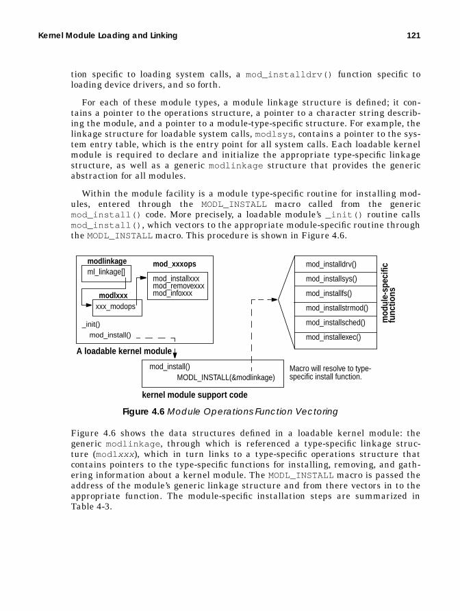
Kernel Module Loading and Linking 121
tion specific to loading system calls, a mod_installdrv() function specific toloading device drivers, and so forth.
For each of these module types, a module linkage structure is defined; it con-tains a pointer to the operations structure, a pointer to a character string describ-ing the module, and a pointer to a module-type-specific structure. For example, thelinkage structure for loadable system calls, modlsys , contains a pointer to the sys-tem entry table, which is the entry point for all system calls. Each loadable kernelmodule is required to declare and initialize the appropriate type-specific linkagestructure, as well as a generic modlinkage structure that provides the genericabstraction for all modules.
Within the module facility is a module type-specific routine for installing mod-ules, entered through the MODL_INSTALL macro called from the genericmod_install() code. More precisely, a loadable module’s _init() routine callsmod_install() , which vectors to the appropriate module-specific routine throughthe MODL_INSTALL macro. This procedure is shown in Figure 4.6.
Figure 4.6 Module Operations Function Vectoring
Figure 4.6 shows the data structures defined in a loadable kernel module: thegeneric modlinkage , through which is referenced a type-specific linkage struc-ture (modl xxx ), which in turn links to a type-specific operations structure thatcontains pointers to the type-specific functions for installing, removing, and gath-ering information about a kernel module. The MODL_INSTALLmacro is passed theaddress of the module’s generic linkage structure and from there vectors in to theappropriate function. The module-specific installation steps are summarized inTable 4-3.
_init()
mod_install()
MODL_INSTALL(&modlinkage)
mod_installdrv()
mod_installsys()
mod_installfs()
mod_installstrmod()
mod_installsched()
mod_installexec()
A loadable kernel module
Macro will resolve to type-specific install function.
modlinkageml_linkage[]
modlxxxxxx_modops
mod_install()
kernel module support code
mod_xxxops
mod_installxxxmod_removexxxmod_infoxxx
mod
ule-
spec
ific
func
tions

122 Kernel Bootstrap and Initialization
The summary column in Table 4-3 shows a definite pattern to the module installa-tion functions. In many subsystems, the kernel implements a switch table mecha-nism to vector to the correct kernel functions for a specific file system, schedulingclass, exec function, etc. The details of each implementation are covered in subse-quent areas of the book, as applicable to a particular chapter or heading.
As we’ve seen, the dynamic loading of a kernel module is facilitated through twomajor kernel subsystems: the module management code and the kernel runtimelinker. These kernel components make use of other kernel services, such as thekernel memory allocator, kernel locking primitives, and the kernel ksyms driver,taking advantage of the modular design of the system and providing a good exam-ple of the layered model discussed earlier.
Table 4-3 Module Install Routines
ModuleType
Install Function Summary
Device driver mod_installdrv Wrapper for ddi_installdrv() .Install the driver entry in the ker-nel devops table.
System call mod_installsys Install the system call’s sysenttable entry in the kernel sysenttable.
File system mod_installfs Installs the file system Virtual FileSystem (VFS) switch table entry.
STREAMSmodules
mod_installstrmod Install the STREAMS entry in thekernel fmodsw switch table.
Schedulingclass
mod_installsched Install the scheduling class in thekernel sclass array.
Exec module mod_installexec Install the exec entry in the kernelexecsw switch table.
Part Two
THE SOLARISMEMORY SYSTEM
• Solaris Memory Architecture• Kernel Memory• Memory Monitoring
123

124

5
SOLARIS MEMORYARCHITECTURE
The virtual memory system can be considered the core of a Solaris system, andthe implementation of Solaris virtual memory affects just about every other sub-system in the operating system. In this chapter, we’ll take a look at some of thememory management basics and then step into a more detailed analysis of howSolaris implements virtual memory management. Subsequent chapters in PartTwo discuss kernel memory management and that can be used to monitor andmanage virtual memory.
5.1 Why Have a Virtual Memory System?
A virtual memory system offers the following benefits:
• It presents a simple memory programming model to applications so thatapplication developers need not know how the underlying memory hardwareis arranged.
• It allows processes to see linear ranges of bytes in their address space,regardless of the physical layout or fragmentation of the real memory.
• It gives us a programming model with a larger memory size than availablephysical storage (e.g., RAM) and enables us to use slower but larger second-ary storage (e.g., disk) as a backing store to hold the pieces of memory thatdon’t fit in physical memory.
125

126 Solaris Memory Architecture
A virtual view of memory storage, known as an address space, is presented to theapplication while the VM system transparently manages the virtual storagebetween RAM and secondary storage. Because RAM is significantly faster thandisk, (100 ns versus 10 ms, or approximately 100,000 times faster), the job of theVM system is to keep the most frequently referenced portions of memory in thefaster primary storage. In the event of a RAM shortage, the VM system is requiredto free RAM by transferring infrequently used memory out to the backing store. Byso doing, the VM system optimizes performance and removes the need for users tomanage the allocation of their own memory.
Multiple users’ processes can share memory within the VM system. In a mul-tiuser environment, multiple processes can be running the same process execut-able binaries; in older Unix implementations, each process had its own copy of thebinary—a vast waste of memory resources. The Solaris virtual memory systemoptimizes memory use by sharing program binaries and application data amongprocesses, so memory is not wasted when multiple instances of a process are exe-cuted. The Solaris kernel extended this concept further when it introduced dynam-ically linked libraries in SunOS, allowing C libraries to be shared amongprocesses.
To properly support multiple users, the VM system implements memory protec-tion. For example, a user’s process must not be able access the memory of anotherprocess, otherwise security could be compromised or a program fault in one pro-gram could cause another program (or the entire operating system) to fail. Hard-ware facilities in the memory management unit perform the memory protectionfunction by preventing a process from accessing memory outside its legal addressspace (except for memory that is explicitly shared between processes).
Physical memory (RAM) is divided into fixed-sized pieces called pages. The sizeof a page can vary across different platforms; the common size for a page of mem-ory on an UltraSPARC Solaris system is 8 Kbytes. Each page of physical memoryis associated with a file and offset; the file and offset identify the backing store forthe page. The backing store is the location to which the physical page contents willbe migrated (known as a page-out) should the page need to be taken for anotheruse; it’s also the location the file will be read back in from if it’s migrated in(known as a page-in). Pages used for regular process heap and stack, known asanonymous memory, have the swap file as their backing store. A page can also be acache of a page-sized piece of a regular file. In that case, the backing store is sim-ply the file it’s caching—this is how Solaris uses the memory system to cache files.
If the virtual memory system needs to take a dirty page (a page that has had itscontents modified), its contents are migrated to the backing store. Anonymousmemory is paged out to the swap device when the page is freed. If a file page needsto be freed and the page size piece of the file hasn’t been modified, then the pagecan simply be freed; if the piece has been modified, then it is first written back outto the file (the backing store in this case), then freed.
Rather than managing every byte of memory, we use page-sized pieces of mem-ory to minimize the amount of work the virtual memory system has to do to main-

Why Have a Virtual Memory System? 127
tain virtual to physical memory mappings. Figure 5.1 shows how the managementand translation of the virtual view of memory (the address space) to physical mem-ory is performed by hardware, known as the virtual memory management unit(MMU).
Figure 5.1 Solaris Virtual-to-Physical Memory Management
The Solaris kernel breaks up the linear virtual address space into segments, onefor each type of memory area in the address space. For example, a simple processhas a memory segment for the process binary and one for the scratch memory(known as heap space). Each segment manages the mapping for the virtualaddress range mapped by that segment and converts that mapping into MMUpages. The hardware MMU maps those pages into physical memory by using aplatform-specific set of translation tables. Each entry in the table has the physicaladdress of the page of memory in RAM, so that memory accesses can be convertedon-the-fly in hardware. We cover more on how the MMU works later in the chap-ter when we discuss the platform-specific implementations of memory manage-ment.
Recall that we can have more virtual address space than physical address spacebecause the operating system can overflow memory onto a slower medium, like adisk. The slower medium in Unix is known as swap space. Two basic types of mem-ory management manage the allocation and migration of physical pages of mem-ory to and from swap space: swapping and demand paging.
V P
0000
ProcessBinary
ProcessScratchMemory
Process’sLinear VirtualAddress Space
VirtualMemorySegments Virtual
Memory
MMU
Virtual-to-PhysicalTranslationTables
PhysicalMemory
(Heap)
PhysicalMemoryPagesPage size
Pieces of

128 Solaris Memory Architecture
The swapping algorithm for memory management uses a user process as thegranularity for managing memory. If there is a shortage of memory, then all of thepages of memory of the least active process are swapped out to the swap device,freeing memory for other processes. This method is easy to implement, but perfor-mance suffers badly during a memory shortage because a process cannot resumeexecution until all of its pages have been brought back from secondary storage.The demand-paged model uses a page as the granularity for memory manage-ment. Rather than swapping out a whole process, the memory system just swapsout small, least used chunks, allowing processes to continue while an inactive partof the process is swapped out.
The Solaris kernel uses a combined demand-paged and swapping model.Demand paging is used under normal circumstances, and swapping is used only asa last resort when the system is desperate for memory. We cover swapping andpaging in more detail in “The Page Scanner” on page 178.
The Solaris VM system implements many more functions than just manage-ment of application memory. In fact, the Solaris virtual memory system is respon-sible for managing most objects related to I/O and memory, including the kernel,user applications, shared libraries, and file systems. This strategy differs signifi-cantly from other operating systems like earlier versions of System V Unix, wherefile system I/O used a separate buffer cache
One of the major advantages of using the VM system to manage file systembuffering is that all free memory in the system is used for file buffering, providingsignificant performance improvements for applications that use the file system andremoving the need for tuning the size of the buffer cache. The VM system can allo-cate all free memory for file system buffers, meaning that on a typical system withfile system I/O, the amount of free memory available is almost zero. This numbercan often be misleading and has resulted in numerous, bogus, memory-leak bugsbeing logged over the years. Don’t worry, “almost zero” is normal. (Note that freememory is no longer always low with Solaris 8.)
In summary, a VM system performs these major functions:
• It manages virtual-to-physical mapping of memory• It manages the swapping of memory between primary and secondary storage
to optimize performance• It handles requirements of shared images between multiple users and pro-
cesses
5.2 Modular Implementation
Early SunOS versions (SunOS 3 and earlier) were based on the old BSD-stylememory system, which was not modularlized, and thus it was difficult to move the

Modular Implementation 129
memory system to different platforms. The virtual memory system was completelyredesigned at that time, with the new memory system targeted at SunOS 4.0. Thenew SunOS 4.0 virtual memory system was built with the following goals in mind:
• Use of a new object-oriented memory management framework• Support for shared and private memory (copy-on-write)• Page-based virtual memory management
The VM system that resulted from these design goals provides an open frameworkthat now supports many different memory objects. The most important objects ofthe memory system are segments, vnodes , and pages. For example, all of the fol-lowing have been implemented as abstractions of the new memory objects:
• Physical memory, in chunks called pages• A new virtual file object, known as the vnode
• File systems as hierarchies of vnodes
• Process address spaces as segments of mapped vnodes
• Kernel address space as segments of mapped vnodes
• Mapped hardware devices, such as frame buffers, as segments of hard-ware-mapped pages
The Solaris virtual memory system we use today is implemented according to theframework of the SunOS 4.0 rewrite. It has been significantly enhanced to providescalable performance on multiprocessor platforms and has been ported to manyplatforms. Figure 5.2 shows the layers of the Solaris virtual memory implementa-tion.
Physical memory management is done by the hardware MMU and a hard-ware-specific address translation layer known as the Hardware Address Transla-tion (HAT) layer. Each memory management type has its own specific HATimplementation. Thus, we can separate the common machine-independent mem-ory management layers from the hardware-specific components to minimize theamount of platform-specific code that must be written for each new platform.
The next layer is the address space management layer. Address spaces are map-pings of segments, which are created with segment device drivers. Each segmentdriver manages the mapping of a linear virtual address space into memory pagesfor different device types (for example, a device such as a graphics frame buffercan be mapped into an address space). The segment layers manage virtual mem-ory as an abstraction of a file. The segment drivers call into the HAT layer to cre-ate the translations between the address space they are managing and theunderlying physical pages.

130 Solaris Memory Architecture
5.3 Virtual Address Spaces
The virtual address space of a process is the range of memory addresses that arepresented to the process as its environment; some addresses are mapped to physi-cal memory, some are not. A process’s virtual address space skeleton is created bythe kernel at the time the fork() system call creates the process. (See “ProcessCreation” on page 293.) The virtual address layout within a process is set up bythe dynamic linker and sometimes varies across different hardware platforms. Aswe saw in Figure 5.1 on page 127, virtual address spaces are assembled from aseries of memory segments. Each process has at least four segments:
sun4-mmusun4msr-mmu
sun4mHAT layer
sun4dsr-mmu
sun4dHAT layer
sun4usf-mmu
sun4uHAT layer
x86i386 mmu
x86HAT layer
sun4c
sun4cHAT layer
Hardware Address Translation (HAT) Layer
segkmem
Kernel MemorySegment
segmap
File Cache MemorySegment
segvn
Process MemorySegment
Address Space Management
32/32-bit 32/36-bit 32/36-bit 64/64-bit 32/36-bit4K pages 4K pages 4K pages 8K/4M pages 4K pages
Global Page Replacement Manager — Page Scanner
Figure 5.2 Solaris Virtual Memory Layers

Virtual Address Spaces 131
• Executable text — The executable instructions in the binary reside in thetext segment. The text segment is mapped from the on-disk binary and ismapped read-only, with execute permissions.
• Executable data — The initialized variables in the executable reside in thedata segment. The data segment is mapped from the on-disk binary and ismapped read/write/private. The private mapping ensures that changes madeto memory within this mapping are not reflected out to the file or to otherprocesses mapping the same executable.
• Heap space — Scratch, or memory allocated by malloc() , is allocated fromanonymous memory and is mapped read/write.
• Process stack — The stack is allocated from anonymous memory and ismapped read/write.
Figure 5.3 illustrates a process’s virtual address space.
Figure 5.3 Process Virtual Address Space
Figure 5.3 shows how the /sbin/sh process has its executable mapped in near thebottom address, with the heap adjoining it, the stack at the top, and a holebetween the heap and the stack. The heap grows upward as more memory is allo-cated through malloc() , and the stack grows downward as more frames areplaced on the stack. Not all of the virtual address space within a process ismapped, and the process can legally access memory only within the areas mappedby segments; a process’s attempt to access memory outside of the mapped seg-ments causes a page fault. A more sophisticated process may have more segments;those that make use of shared libraries or mapped files will have additional seg-ments between the heap and stack.
Binary (Text)
Variables (Data)
Heap
Stack
Executable
Malloc’d Memory
/sbin/sh
malloc()
Stack FrameTop of Virtual Address Space
Virtual Address 0x0

132 Solaris Memory Architecture
5.3.1 Sharing of Executables and Libraries
The Solaris kernel supports sharing of memory, files, libraries, and executables.For example, the Solaris kernel shares libraries by dynamically mapping thelibrary file into the address space during program startup. The libraries aremapped into the address space between the stack and the heap, at different posi-tions on different platforms.
When a library file is mapped into a process’s address space, it can be mappedshared so that all processes share the same physical memory pages. Executabletext and data are shared in the same manner, by simply mapping the same execut-able file into every address space.
We’ll see more about how mapping of files and sharing of memory occur whenwe explore the vnode segment driver, which is responsible for mapping files intoaddress spaces.
5.3.2 SPARC Address Spaces
The process address space on SPARC system varies across different SPARC plat-forms according to the MMU on that platform. SPARC has three different addressspace layouts:
• The SPARC V7 combined 32-bit kernel and process address space, found onsun4c, sun4d, and sun4m machines
• The SPARC V9 32-bit separated kernel and process address space model,found on sun4u machines
• The SPARC V9 64-bit separated kernel and process address space model,found on sun4u machines.
The SPARC V7 systems use a shared address space between the kernel and pro-cess and use the processor’s privilege levels to prevent user processes from access-ing the kernel’s address space. The kernel occupies the top virtual memoryaddresses, and the process occupies the lower memory addresses. This means thatpart of the virtual address space available to the process is consumed by the ker-nel, limiting the size of usable process virtual memory to between 3.5 and 3.75Gbytes, depending on the size of the kernel’s virtual address space. This alsomeans that the kernel has a limited size, ranging between 128 and 512 Mbytes.

Virtual Address Spaces 133
The SPARC V7 combined 32-bit kernel and process address space is shown in Fig-ure 5.4.
Figure 5.4 SPARC 32-Bit Shared Kernel/Process Address Space
The SPARC V9 (UltraSPARC, sun4u) microprocessor allows the kernel to operatein an address space separate from user processes, so the process can use almost allof the 32-bit address space (a tiny bit is reserved at the top for the Open BootPROM) and also allows the kernel to have a similar large address space. Thisdesign removes the 512-Mbyte limit for kernel address space, which was a majorproblem for large machines such as the older SPARCcenter 2000 machines. Theprocess address space looks similar to the shared kernel/process address space,except that the kernel area is missing and the stack and libraries are moved to thetop of memory.
The UltraSPARC process also supports the SPARC V9 64-bit mode, whichallows a process to have a virtual address space that spans 64 bits. The Ultra-SPARC-I and -II implementations, however, support only 44 bits of the addressspace, which means that there is a virtual address space hole in the middle of theaddress space. This area of memory creates a special type of UltraSPARC trapwhen accessed. Some future generations of SPARC V9 processors will not have thesame hole in the address space.
The UltraSPARC V9 32-bit and 64-bit address spaces are shown in Figure 5.5.
Executable – TEXT
Executable – DATA
HEAP– malloc(), sbrk()
Stack
Libraries
0x00010000
0xEF7EA000
0xEFFFC000
Executable – TEXT
Executable – DATA
HEAP – malloc(), sbrk()
Stack
Libraries
0x00010000
0xDF7F9000
0xDFFFE000
0xFFFFFFFF 0xFFFFFFFF256-MB Kernel Context
512-MB Kernel Context
sun4c, sun4m sun4d

134 Solaris Memory Architecture
Figure 5.5 SPARC sun4u 32- and 64-Bit Process Address Space
On all SPARC platforms, the bottom of the virtual address space is not mapped.Null pointer references will cause a segmentation fault rather than return spuri-ous contents of whatever was at the bottom of the address space.
5.3.3 Intel Address Space Layout
The Intel x86 address space, like the 32-bit SPARCV7 shared process/kerneladdress space, shares the same address space for user and kernel. The main differ-ence with the Intel address space is that the stack is mapped underneath the exe-cutable binary and grows down toward the bottom. The Intel address space isshown in Figure 5.6.
5.3.4 Process Memory Allocation
Process virtual memory for user data structures is allocated from the heap seg-ment, which resides above the executable data segment. The heap starts out smalland then grows as virtual memory is allocated. The heap grows in units of pagesand is simply a large area of virtual memory available for reading and writing. Asingle, large, virtual memory area is difficult to program to, so a general-purpose
Executable – TEXT
Executable – DATA
HEAP – malloc(),
Stack
Libraries
0x00010000
0xFF3DC000
0xFFBEC000
32-bit sun4u
0x0000001.000000000
0xFFFFFFFF.7F7F0000
0xFFFFFFFF.7FFFC000
64-bit sun4u
Executable – TEXT
Executable – DATA
HEAP -– malloc(),
Stack
Libraries
VA Hole0x00000800.00000000
0xFFFFF7FF.FFFFFFFF
sbrk() sbrk()

Virtual Address Spaces 135
memory allocator manages the heap area; thus, arbitrarily sized memory objectscan be allocated and freed. The general-purpose memory allocator is implementedwith malloc() and related library calls.
A process grows its heap space by making the sbrk() system call. The sbrk()system call grows the heap segment by the amount requested each time it iscalled. A user program does not need to call sbrk() directly because the mal-loc() library calls sbrk() when it needs more space to allocate from. Thesbrk() system call is shown below.
The heap segment is virtual memory, so requesting memory with malloc andsbrk does not allocate physical memory, it merely allocates the virtual addressspace. Only when the first reference is made to a page within the allocated virtualmemory is physical memory allocated—one page at a time. The memory systemtransparently achieves this “zero fill on demand” allocation because a page faultoccurs the first time a page is referenced in the heap, and then the segment driverrecognizes the first memory access and simply creates a page at that locationon-the-fly.
void *sbrk(intptr_t incr);
Executable – TEXT
Executable – DATA
HEAP– malloc(), sbrk()
Stack
Libraries
0xE0000000
0x8048000
0xFFFFFFFF256-MB Kernel Context
Intel x86
0x0
Figure 5.6 Intel x86 Process Address Space

136 Solaris Memory Architecture
Memory pages are allocated to the process heap by zero-fill-on-demand and thenremain in the heap segment until the process exits or until they are stolen by thepage scanner. Calls to the memory allocator free() function do not return physi-cal memory to the free memory pool; free() simply marks the area within theheap space as free for later use. For this reason, it is typical to see the amount ofphysical memory allocated to a process grow, but unless there is a memory short-age, it will not shrink, even if free() has been called.
The heap can grow until it collides with the memory area occupied by theshared libraries. The maximum size of the heap depends on the platform virtualmemory layout and differs on each platform. In addition, on 64-bit platforms, pro-cesses may execute in either 32- or 64-bit mode. As shown in Figure 5.5 onpage 134, the size of the heap can be much larger in processes executing in 64-bitmode. Table 5-1 shows the maximum heap sizes and the operating system require-ments that affect the maximum size.
5.3.5 The Stack
The process stack is mapped into the address space with an initial allocation andthen grows downward. The stack, like the heap, grows on demand, but no librarygrows the stack; instead, a different mechanism triggers this growth.
Initially, a single page is allocated for the stack, and as the process executes andcalls functions, it pushes the program counter, arguments, and local variables ontothe stack. When the stack grows larger than one page, the process causes a pagefault, and the kernel notices that this is a stack segment page fault and grows thestack segment.
Table 5-1 Maximum Heap Sizes
Solaris Version Maximum HeapSize
Notes
Solaris 2.5 2 GbytesSolaris 2.5.1 2 GbytesSolaris 2.5.1 with patch103640-08 or greater
3.75 Gbytes Need to be root toincrease limit above 2GB with ulimit (1M).
Solaris 2.5.1 with patch103640-23 or greater
3.75 Gbytes Do not need to be root toincrease limit.
Solaris 2.6 3.75 Gbytes Need to increase beyond2 GB with ulimit (1M).
Solaris 2.7 32 bit mode 3.75 Gbytes3.90 Gbytes
(Non-sun4u platform)(sun4u platforms)
Solaris 2.7 64 bit mode 16 Tbytes onUltraSPARC-I and -II
Virtually unlimited.

Virtual Address Spaces 137
5.3.6 Address Space Management
The Solaris kernel is implemented with a central address management subsystemthat other parts of the kernel call into. The address space module is a wrapperaround the segment drivers, so that subsystems need not know what segmentdriver is used for a memory range. The address space object shown in Figure 5.7 islinked from the process’s address space and contains pointers to the segments thatconstitute the address space.
The address space subsystem manages the following functions:
• Duplication of address spaces, for fork()
• Destruction of address spaces, for exit()
• Creation of new segments within an address space• Removal of segments from an address space• Setting and management of page protection for an address space• Page fault routing for an address space
a_segs
struct as
a_sizea_nsegsa_flagsa_hata_tail
p_as
struct proc s_base
struct seg
s_sizes_ass_prevs_nexts_ops
s_base
struct seg
s_sizes_ass_prevs_nexts_ops
s_base
struct seg
s_sizes_ass_prevs_nexts_ops
Executable – TEXT
Executable – DATA
HEAP– malloc(), sbrk()
Stack
Libraries
256-MB Kernel Context
a_watchp
Figure 5.7 The Address Space

138 Solaris Memory Architecture
• Page locking and advice for an address space• Management of watchpoints for an address space
Recall that the process and kernel subsystems call into the address space sub-system to manage their address spaces. The address space subsystem consists of aseries of functions, grouped to perform the functions listed above. Although thesubsystem has a lot of entry points, the implementation is fairly simple becausemost of the functions simply look up which segment the operation needs to oper-ate on and then route the request to the appropriate segment driver.
A call to the as_alloc() function creates an address space, but as_alloc() isinvoked only once—when the system boots and the init process is created. Afterthe init process is created, all address spaces are created by duplication of the initprocess’s address space with fork() . The fork() system call in turn calls theas_dup() function to duplicate the address space of current process as it creates anew process, and the entire address space configuration, including the stack andheap, is replicated at this point.
The behavior of vfork() at this point is somewhat different. Rather than callingas_dup() to replicate the address space, vfork() creates a new process by bor-rowing the parent’s existing address space. The vfork function is useful if the forkis going to call exec() since it saves all the effort of duplicating the address spacethat would otherwise have been discarded once exec() is called. The parent pro-cess is suspended while the child is using its address space, until exec() is called.Once the process is created, the address space object is allocated and set up. TheSolaris 7 data structure for the address space object is shown below.
struct as { kmutex_t a_contents; /* protect certain fields in the structure */ uchar_t a_flags; /* as attributes */ uchar_t a_vbits; /* used for collecting statistics */ kcondvar_t a_cv; /* used by as_rangelock */ struct hat *a_hat; /* hat structure */ struct hrmstat *a_hrm; /* ref and mod bits */ caddr_t a_userlimit; /* highest allowable address in this as */ union { struct seg *seglast; /* last segment hit on the addr space */ ssl_spath *spath; /* last search path in seg skiplist */ } a_cache; krwlock_t a_lock; /* protects fields below + a_cache */ int a_nwpage; /* number of watched pages */ struct watched_page *a_wpage; /* list of watched pages (procfs) */ seg_next a_segs; /* segments in this address space. */ size_t a_size; /* size of address space */ struct seg *a_tail; /* last element in the segment list. */ uint_t a_nsegs; /* number of elements in segment list */ uchar_t a_lrep; /* representation of a_segs: see #defines */ uchar_t a_hilevel; /* highest level in the a_segs skiplist */ uchar_t a_unused; uchar_t a_updatedir; /* mappings changed, rebuild as_objectdir */ vnode_t **a_objectdir; /* object directory (procfs) */ size_t a_sizedir; /* size of object directory */};
Header File <vm/as.h>
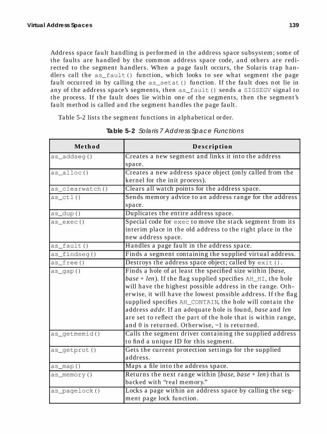
Virtual Address Spaces 139
Address space fault handling is performed in the address space subsystem; some ofthe faults are handled by the common address space code, and others are redi-rected to the segment handlers. When a page fault occurs, the Solaris trap han-dlers call the as_fault() function, which looks to see what segment the pagefault occurred in by calling the as_setat() function. If the fault does not lie inany of the address space’s segments, then as_fault() sends a SIGSEGVsignal tothe process. If the fault does lie within one of the segments, then the segment’sfault method is called and the segment handles the page fault.
Table 5-2 lists the segment functions in alphabetical order.
Table 5-2 Solaris 7 Address Space Functions
Method Descriptionas_addseg() Creates a new segment and links it into the address
space.as_alloc() Creates a new address space object (only called from the
kernel for the init process).as_clearwatch() Clears all watch points for the address space.as_ctl() Sends memory advice to an address range for the address
space.as_dup() Duplicates the entire address space.as_exec() Special code for exec to move the stack segment from its
interim place in the old address to the right place in thenew address space.
as_fault() Handles a page fault in the address space.as_findseg() Finds a segment containing the supplied virtual address.as_free() Destroys the address space object; called by exit() .as_gap() Finds a hole of at least the specified size within [base,
base + len). If the flag supplied specifies AH_HI, the holewill have the highest possible address in the range. Oth-erwise, it will have the lowest possible address. If the flagsupplied specifies AH_CONTAIN, the hole will contain theaddress addr. If an adequate hole is found, base and lenare set to reflect the part of the hole that is within range,and 0 is returned. Otherwise, −1 is returned.
as_getmemid() Calls the segment driver containing the supplied addressto find a unique ID for this segment.
as_getprot() Gets the current protection settings for the suppliedaddress.
as_map() Maps a file into the address space.as_memory() Returns the next range within [base, base + len) that is
backed with “real memory.”as_pagelock() Locks a page within an address space by calling the seg-
ment page lock function.

140 Solaris Memory Architecture
5.3.7 Virtual Memory Protection Modes
We break each process into segments so that we can treat each part of the addressspace differently. For example, the kernel maps the machine code portion of theexecutable binary into the process as read-only to prevent the process from modify-ing its machine code instructions. The virtual memory subsystem does this by tak-ing advantage of the hardware MMU’s virtual memory protection capabilities.Solaris relies on the MMU having the following protection modes:
• Read — The mapping is allowed to be read from.• Write — The mapping is allowed to be written to.
• Executable — The mapping is allowed to have machine codes executed withinits address range.
The implementation of protection modes is done in the segment and HAT layers.
5.3.8 Page Faults in Address Spaces
The Solaris virtual memory system uses the hardware MMU’s memory manage-ment capabilities. MMU-generated exceptions tell the operating system when amemory access cannot continue without the kernel’s intervention, by interrupting
as_pagereclaim() Retrieves a page from the free list for the address sup-plied.
as_pageunlock() Unlocks a page within the address space.as_rangebroadcast () Wakes up all threads waiting on the address space condi-
tion variable.as_rangelock() Locks the pages for the supplied address range.as_rangeunlock() Unlocks the pages for the supplied address range.as_rangewait() Waits for virtual addresses to become available in the
specified address space. AS_CLAIMGAP must be held bythe caller and is reacquired before returning to the caller.
as_setat() Finds a segment containing the supplied address.as_setprot() Sets the virtual mapping for the interval from [addr :
addr + size) in address space as to have the specified pro-tection.
as_setwatch() Sets a watchpoint for the address. On a system withoutwatchpoint support, does nothing.
as_swapout() Swaps the pages associated with the address space to sec-ondary storage, returning the number of bytes actuallyswapped.
as_unmap() Unmaps a segment from the address space.
Table 5-2 Solaris 7 Address Space Functions (Continued)
Method Description

Virtual Address Spaces 141
the executing process with a trap (see “Entering Kernel Mode” on page 28) andthen invoking the appropriate piece of memory management code. Three majortypes of memory-related hardware exceptions can occur: major page faults, minorpage faults, and protection faults.
A major page fault occurs when an attempt to access a virtual memory locationthat is mapped by a segment does not have a physical page of memory mapped toit and the page does not exist in physical memory. The page fault allows the vir-tual memory system to hide the management of physical memory allocation fromthe process. The virtual memory system traps accesses to memory that the pro-cess believes is accessible and arranges to have either a new page created for thataddress (in the case of the first access) or copies in the page from the swap device.Once the memory system places a real page behind the memory address, the pro-cess can continue normal execution. If a reference is made to a memory addressthat is not mapped by any segment, then a segmentation violation signal (SIG-SEGV) is sent to the process. The signal is sent as a result of a hardware exceptioncaught by the processor and translated to a signal by the address space layer.
A minor page fault occurs when an attempt is made to access a virtual memorylocation that resides within a segment and the page is in physical memory, but nocurrent MMU translation is established from the physical page to the addressspace that caused the fault. For example, a process maps in the libc.so libraryand makes a reference to a page within it. A page fault occurs, but the physicalpage of memory is already present and the process simply needs to establish amapping to the existing physical page. Minor faults are also referred to asattaches.
A page protection fault occurs when a program attempts to access a memoryaddress in a manner that violates the preconfigured access protection for a mem-ory segment. Protection modes can enable any of read, write, or execute access. Forexample, the text portion of a binary is mapped read-only, and if we attempt towrite to any memory address within that segment, we will cause a memory protec-tion fault. The memory protection fault is also initiated by the hardware MMU asa trap that is then handled by the segment page fault handling routine.

142 Solaris Memory Architecture
Figure 5.8 shows the relationship between a virtual address space, its segments,and the hardware MMU.
Figure 5.8 Virtual Address Space Page Fault Example
In the figure, we see what happens when a process accesses a memory locationwithin its heap space that does not have physical memory mapped to it. This hasmost likely occurred because the page of physical memory has previously been sto-len by the page scanner as a result of a memory shortage.
1. A reference is made to a memory address that does not map to a physicalpage of memory. In this example, the page has been paged out and nowresides on the swap device.
2. When the process accesses the address with no physical memory behind it,the MMU detects the invalid reference and causes a trap to occur on the pro-cessor executing the code of the running thread. The fault handler recognizesthis as a memory page fault and establishes which segment the fault occurredin by comparing the address of the fault to the addresses mapped by eachsegment.
3. The address space as_fault() routine compares the address of the faultwith the addresses mapped by each segment and then calls the page_fault
Vnode Segment Driver
Segment Size
Virtual Base Address
.
.
TEXT
DATA
HEAP
Stack
Libraries
sun4usf-mmu
sun4uhat layerPage Fault
seg_fault()
Address Space
segvn_fault()
vop_getpage()
swapfs
SwapSpace
segvn
Page The page is
(points to vnode segmentdriver)
(trap)
1
2
4
5
6A byte is touched in
The segment driver
copied fromswap to memory.
the heap space, causingan MMU page fault.
fault handler is calledto handle the fault bybringing it in fromswap.
3The address space determinesfrom the address of the faultwhich segment the fault occurredin and calls the segment driver.

Memory Segments 143
routine of the segment driver for this segment (in this case, the vnode seg-ment driver).
4. The segment driver allocates and maps page of memory by calling into theHAT layer and then copies the contents of the page from the swap device.
5. The segment driver then reads the page in from the backing store by callingthe getpage() function of the backing store’s vnode .
6. The backing store for this segment is the swap device, so the swap devicegetpage() function is called to read in the page from the swap device.
Once this process is completed, the process can continue execution.
5.4 Memory Segments
Another example of the object-oriented approach to memory management is thememory “segment” object. Memory segments manage the mapping of a linearrange of virtual memory into an address space. The mapping is between theaddress space and some type of device. The objective of the memory segment is toallow both memory and devices to be mapped into an address space. Traditionally,this required hard-coding memory and device information into the address spacehandlers for each device. The object architecture allows different behaviors for dif-ferent segments.
For example, one segment might be a mapping of a file into an address space(with mmap), and another segment might be the mapping of a hardware device intothe process’s address space (a graphics framebuffer). In this case, the segmentdriver provides a similar view of linear address space, even though the file map-ping operation with mmapuses pages of memory to cache the file data, whereas theframebuffer device maps the hardware device into the address space.
The flexibility of the segment object allows us to use virtually any abstraction torepresent a linear address space that is visible to a process, regardless of the realfacilities behind the scenes.
struct seg { caddr_t s_base; /* base virtual address */ size_t s_size; /* size in bytes */ struct as *s_as; /* containing address space */ seg_next s_next; /* next seg in this address space */ struct seg *s_prev; /* prev seg in this address space */ struct seg_ops *s_ops; /* ops vector: see below */ void *s_data; /* private data for instance */};
Header File <vm/seg.h>

144 Solaris Memory Architecture
To implement an address space, a segment driver implementation is required toprovide at least the following: functions to create a mapping for a linear addressrange, page fault handling routines to deal with machine exceptions within thatlinear address range, and a function to destroy the mapping. These functions arepackaged together into a segment driver, which is an instantiation of the segmentobject interface. Figure 5.9 illustrates the relationship between an address spaceand a segment and shows a segment mapping the heap space of a process.
A segment driver implements a subset of the methods described in Table 5-4 onpage 146, as well as a constructor function to create the first instance of the object.Functions in the segment operations structure, s_ops , point to functions withinthe vnode segment driver and are prefixed with segvn . A segment object is cre-ated when another subsystem wants to create a mapping by calling as_map() tocreate a mapping at a specific address. The segment’s create routine is passed asan argument to as_map() , a segment object is created, and a segment objectpointer is returned. Once the segment is created, other parts of the virtual mem-ory system can call into the segment for different address space operations with-out knowing what the underlying segment driver is using the segment methodoperations for.
For example, when a file is mapped into an address space with mmap() , theaddress space map routine as_map() is called with segvn_create() (the vnode
Executable – TEXT
Executable – DATA
HEAP
Stack
Libraries
256-MB Kernel Context
s_base
struct seg
s_sizes_ass_prevs_nexts_ops
segvn_free()segvn_fault()segvn_getprot()segvn_setprot()segvn_incore()
..
s_data
Figure 5.9 Segment Interface

Memory Segments 145
segment driver constructor) as an argument, which in turn calls into the seg_vnsegment driver to create the mapping. The segment object is created and insertedinto the segment list for the address space (struct as ), and from that point on, theaddress space can perform operations on the mapping without knowing what theunderlying segment is.
The address space routines can operate on the segment without knowing whattype of segment is underlying by calling the segment operation macros. For exam-ple, if the address space layer wants to call the fault handler for a segment, it callsSEGOP_FAULT(), which invokes the segment-specific page fault method, as shownbelow.
The Solaris kernel is implemented with a range of segment drivers for variousfunctions. The different types of drivers are shown in Table 5-3. Most of the pro-cess address space mapping—including executable text, data, heap, stack andmemory mapped files—is performed with the vnode segment driver, seg_vn .Other types of mappings that don’t have vnodes associated with them require dif-ferent segment drivers. The other segment drivers are typically associated withkernel memory mappings or hardware devices, such as graphics adapters.
#define SEGOP_FAULT(h, s, a, l, t, rw) \ (*(s)->s_ops->fault)((h), (s), (a), (l), (t), (rw))
Header File <vm/seg.h>
Table 5-3 Solaris 7 Segment Drivers
Segment Functionseg_vn The vnode mappings into process address spaces are managed
with the seg_vn device driver. Executable text and data, sharedlibraries, mapped files, heap and stack (heap and stack are anony-mous memory) are all mapped with seg_vn .
seg_kmem The segment from which the bulk of nonpageable kernel memoryis allocated. (See Chapter 6, “Kernel Memory”.").
seg_kp The segment from which pageable kernel memory is allocated.Only a very small amount of the kernel is pageable; kernel threadstacks and TNF buffers are the main consumers of pageable ker-nel memory.
seg_spt Shared page table segment driver. Fast System V shared memoryis mapped into process address space from this segment driver.Memory allocated from this driver is also known as IntimateShared Memory (ISM).
seg_map The kernel uses the seg_map driver to map files (vnodes ) into thekernel’s address space, to implement file system caching.
seg_dev Mapped hardware devices.
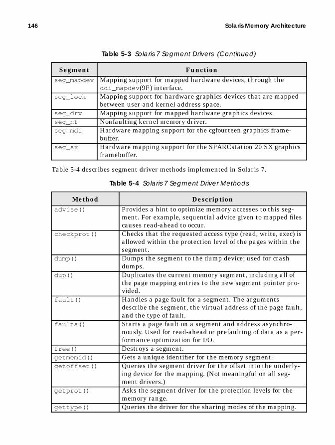
146 Solaris Memory Architecture
Table 5-4 describes segment driver methods implemented in Solaris 7.
seg_mapdev Mapping support for mapped hardware devices, through theddi_mapdev (9F) interface.
seg_lock Mapping support for hardware graphics devices that are mappedbetween user and kernel address space.
seg_drv Mapping support for mapped hardware graphics devices.seg_nf Nonfaulting kernel memory driver.seg_mdi Hardware mapping support for the cgfourteen graphics frame-
buffer.seg_sx Hardware mapping support for the SPARCstation 20 SX graphics
framebuffer.
Table 5-4 Solaris 7 Segment Driver Methods
Method Descriptionadvise() Provides a hint to optimize memory accesses to this seg-
ment. For example, sequential advice given to mapped filescauses read-ahead to occur.
checkprot() Checks that the requested access type (read, write, exec) isallowed within the protection level of the pages within thesegment.
dump() Dumps the segment to the dump device; used for crashdumps.
dup() Duplicates the current memory segment, including all ofthe page mapping entries to the new segment pointer pro-vided.
fault() Handles a page fault for a segment. The argumentsdescribe the segment, the virtual address of the page fault,and the type of fault.
faulta() Starts a page fault on a segment and address asynchro-nously. Used for read-ahead or prefaulting of data as a per-formance optimization for I/O.
free() Destroys a segment.getmemid() Gets a unique identifier for the memory segment.getoffset() Queries the segment driver for the offset into the underly-
ing device for the mapping. (Not meaningful on all seg-ment drivers.)
getprot() Asks the segment driver for the protection levels for thememory range.
gettype() Queries the driver for the sharing modes of the mapping.
Table 5-3 Solaris 7 Segment Drivers (Continued)
Segment Function

Memory Segments 147
5.4.1 The vnode Segment: seg_vn
The most widely used segment driver is the vnode segment driver, seg_vn . Theseg_vn driver maps files (or vnodes ) into a process address space, using physicalmemory as a cache. The seg_vn segment driver also creates anonymous memorywithin the process address space for the heap and stack and provides support forSystem V shared memory. (See “System V Shared Memory” on page 433.)
The seg_vn segment driver manages the following mappings into processaddress space:
• Executable text• Executable data• Heap and stack (anonymous memory)• Shared libraries• Mapped files
5.4.1.1 Memory Mapped Files
We can map a file into a process’s address space with the mmapsystem call. (See asdiscussed in “Memory Mapped File I/O” on page 509.) When we map a file into ouraddress space, we call into the address space routines to create a new segment, avnode segment. A vnode segment handles memory address translation and pagefaults for the memory range requested in the mmapsystem call, and the new seg-ment is added to the list of segments in the process’s address space. When the seg-ment is created, the seg_vn driver initializes the segment structure with the
getvp() Gets the vnode pointer for the vnode , if there is one,behind this mapping.
incore() Queries to find out how many pages are in physical mem-ory for a segment.
kluster() Asks the segment driver if it is OK to cluster I/O opera-tions for pages within this segment.
lockop() Locks or unlocks the pages for a range of memory mappedby a segment.
pagelock() Locks a single page within the segment.setprot() Sets the protection level of the pages with the address
range supplied.swapout() Attempts to swap out as many pages to secondary storage
as possible.sync() Syncs up any dirty pages within the segment to the back-
ing store.unmap() Unmaps the address space range within a segment.
Table 5-4 Solaris 7 Segment Driver Methods (Continued)
Method Description

148 Solaris Memory Architecture
address and length of the mapping, then creates a seg_vn -specific data structurewithin the segment structure’s s_data field. The seg_vn- specific data structureholds all of the information the seg_vn driver needs to handle the address map-pings for the segment.
The seg_vn -specific data structure (struct segvn_data ) contains pointers tothe vnode that is mapped and to any anonymous memory that has been allocatedfor this segment. The file system does most of the work of mapped files once themapping is created. As a result, the seg_vn driver is fairly simple—most of theseg_vn work is done during creation and deletion of the mapping.
The more complex part of the seg_vn driver implementation is its handling ofanonymous memory pages within the segment, which we discuss in the sectionsthat follow. When we create a file mapping, we put the vnode and offset of the filebeing mapped into the segvn_data structure members, vp and offset . Theseg_vn data structure is shown below; Figure 5.10 illustrates the seg_vn seg-ment driver vnode relationship.
Creating a mapping for a file is done with the mmap() system call, which calls themap method for the file system that contains the file. For example, calling mmap()for a file on a UFS file system will call ufs_map() , which in turn calls into theseg_vn driver to create a mapped file segment in the address space with thesegvn_create() function.
At this point we create an actual virtual memory mapping by talking to thehardware through the hardware address translation functions by using thehat_map() function. The hat_map() function is the central function for creatingaddress space mappings. It calls into the hardware-specific memory implementa-tion for the platform to program the hardware MMU, so that memory address ref-erences within the supplied address range will trigger the page fault handler inthe segment driver until a valid physical memory page has been placed at the
struct segvn_data { krwlock_t lock; /* protect segvn_data and vpage array */ uchar_t pageprot; /* true if per page protections present */ uchar_t prot; /* current segment prot if pageprot == 0 */ uchar_t maxprot; /* maximum segment protections */ uchar_t type; /* type of sharing done */ u_offset_t offset; /* starting offset of vnode for mapping */ struct vnode *vp; /* vnode that segment mapping is to */ ulong_t anon_index; /* starting index into anon_map anon array */ struct anon_map *amp; /* pointer to anon share structure, if needed */ struct vpage *vpage; /* per-page information, if needed */ struct cred *cred; /* mapping credentials */ size_t swresv; /* swap space reserved for this segment */ uchar_t advice; /* madvise flags for segment */ uchar_t pageadvice; /* true if per page advice set */ ushort_t flags; /* flags - from sys/mman.h */ ssize_t softlockcnt; /* # of pages SOFTLOCKED in seg */};
Header File <vm/seg_vn.h>

Memory Segments 149
accessed location. Once the hardware MMU mapping is established, the seg_vndriver can begin handling page faults within that segment.
Having established a valid hardware mapping for our file, we can look at howour mapped file is effectively read into the address space. The hardware MMU cangenerate traps for memory accesses to the memory within that segment. Thesetraps will be routed to our seg_vn driver through the as_fault() routine. (See“Page Faults in Address Spaces” on page 140.) The first time we access a memorylocation within our segment, the segvn_fault() page fault handling routine iscalled. This fault handler recognizes our segment as a mapped file (by looking inthe segvn_data structure) and simply calls into the vnode’s file system (in thiscase, with ufs_getpage() ) to read in a page-sized chunk from the file system.The subsequent access to memory that is now backed by physical memory simply
Executable – TEXT
Executable – DATA
HEAP
Stack
Libraries
256-MB Kernel Context
s_base
struct seg
s_sizes_ass_prevs_nexts_ops
segvn_free()segvn_fault()segvn_getprot()segvn_setprot()segvn_incore()
..
s_data
vp
struct
offsetanon_indexanon_mapflags..
segvn_data
struct vnode
MAPPEDFILE
Mapped File
Figure 5.10 The seg_vn Segment Driver Vnode Relationship

150 Solaris Memory Architecture
results in a normal memory access. It’s not until a page is stolen from behind thesegment (the page scanner can do this) that a page fault will occur again.
Writing to a mapped file is done by updating the contents of memory within themapped segment. The file is not updated instantly, since there is no software- orhardware-initiated event to trigger any such write. Updates occur when the filesystem flush daemon finds that the page of memory has been modified and thenpushes the page to the file system with the file systems putpage routine, in thiscase, ufs_putpage() .
5.4.1.2 Shared Mapped Files
The address space segment architecture makes it easy for two or more processes tomap the same file into their address space. When we map files into two or moreprocesses, we create seg_vn segments in each process that point to the samevnode . Each process has its own virtual memory mapping to the file, but they allshare the same physical memory pages for the files. The first segment to cause apage fault reads a page into physical memory, and then the second and subse-quent segments simply create a reference to the existing physical memory page—as attaching.
Figure 5.11shows how two processes can map the same file. Each process cre-ates its own segment object, but both segments point to the same file and aremapped to the same physical pages. Notice that the second process need not haveall of the pages attached to the segment, even if both segments map the sameparts of the file. In this case, the second process would attach to these pages whenthey are referenced. A minor fault is used to describe this event. You can see minorfaults by using vmstat . (See “Statistics from the vmstat Command” on page 242.)
Several options govern how a file is shared when it is mapped between two or moreprocesses. These options control how changes are propagated across the sharedfile. For example, if one process wants to modify one of the pages mapped into theprocess, should the other process see exactly the same change or should the changeremain private to the process that made the change? The options allow us tochoose which behavior we desire. The options are those that can be passed to theprotection and flags argument of mmap() when the file is mapped. The behavior forthe different flags is listed in Table 5-5.
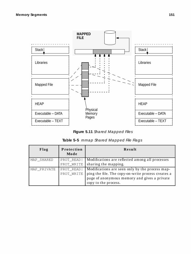
Memory Segments 151
Table 5-5 mmap Shared Mapped File Flags
Flag ProtectionMode
Result
MAP_SHARED PROT_READ|PROT_WRITE
Modifications are reflected among all processessharing the mapping.
MAP_PRIVATE PROT_READ|PROT_WRITE
Modifications are seen only by the process map-ping the file. The copy-on-write process creates apage of anonymous memory and gives a privatecopy to the process.
PhysicalMemoryPages
Executable – TEXT
Executable – DATA
HEAP
Stack
Libraries
Mapped File
Executable – TEXT
Executable – DATA
HEAP
Stack
Libraries
Mapped File
MAPPEDFILE
Figure 5.11 Shared Mapped Files
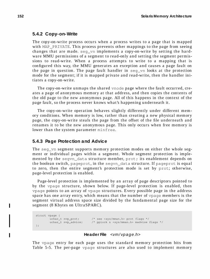
152 Solaris Memory Architecture
5.4.2 Copy-on-Write
The copy-on-write process occurs when a process writes to a page that is mappedwith MAP_PRIVATE. This process prevents other mappings to the page from seeingchanges that are made. seg_vn implements a copy-on-write by setting the hard-ware MMU permissions of a segment to read-only and setting the segment permis-sions to read-write. When a process attempts to write to a mapping that isconfigured this way, the MMU generates an exception and causes a page fault onthe page in question. The page fault handler in seg_vn looks at the protectionmode for the segment; if it is mapped private and read-write, then the handler ini-tiates a copy-on-write.
The copy-on-write unmaps the shared vnode page where the fault occurred, cre-ates a page of anonymous memory at that address, and then copies the contents ofthe old page to the new anonymous page. All of this happens in the context of thepage fault, so the process never knows what’s happening underneath it.
The copy-on-write operation behaves slightly differently under different mem-ory conditions. When memory is low, rather than creating a new physical memorypage, the copy-on-write steals the page from the offset of the file underneath andrenames it to be the new anonymous page. This only occurs when free memory islower than the system parameter minfree .
5.4.3 Page Protection and Advice
The seg_vn segment supports memory protection modes on either the whole seg-ment or individual pages within a segment. Whole segment protection is imple-mented by the segvn_data structure member, prot; its enablement depends onthe boolean switch, pageprot , in the segvn_data structure. If pageprot is equalto zero, then the entire segment’s protection mode is set by prot ; otherwise,page-level protection is enabled.
Page-level protection is implemented by an array of page descriptors pointed toby the vpage structure, shown below. If page-level protection is enabled, thenvpage points to an array of vpage structures. Every possible page in the addressspace has one array entry, which means that the number of vpage members is thesegment virtual address space size divided by the fundamental page size for thesegment (8 Kbytes on UltraSPARC).
The vpage entry for each page uses the standard memory protection bits fromTable 5-5. The per-page vpage structures are also used to implement memory
struct vpage { uchar_t nvp_prot; /* see <sys/mman.h> prot flags */ uchar_t nvp_advice; /* pplock & <sys/mman.h> madvise flags */};
Header File <vm/vpage.h>

Anonymous Memory 153
advice for memory mapped files in the seg_vn segment. (See “Providing Advice tothe Memory System” on page 513.)
5.5 Anonymous Memory
At many points we have mentioned anonymous memory. Anonymous memoryrefers to pages that are not directly associated with a vnode . Such pages are usedfor a process’s heap space, its stack, and copy-on-write pages. In the Solaris ker-nel, two subsystems are dedicated to managing anonymous memory: the anonlayer and the swapfs file system.
The anonymous memory allocated to the heap of a process is a result of azero-fill-on-demand operation (ZFOD). The ZFOD operation is how we allocate newpages. A ZFOD occurs when we touch a memory address for the first time, and anew page of memory is dynamically allocated at that address. ZFOD is the alloca-tion method used for the heap space and segments created as a map of /dev/zerowith segment protection of MAP_PRIVATE. A page fault on a segment of this typewill be recognized as ZFOD, and a new zeroed anonymous memory page is createdat the fault location. The seg_vn segment fault handler, segvn_fault , handlesthe fault and creates ZFOD pages.
The seg_vn segment driver allocates anonymous memory to the segment bycalling into the anonymous memory layer interfaces and attaching anonymousmaps to the amp (anonymous map pointer) member in the segvn_data structure.Figure 5.12 shows a seg_vn segment with the anonymous map structures allo-cated to it.
Every allocated page-sized piece of virtual memory in the segment is assigned ananonymous map slot. For example, when a segment is first created, there are noanonymous map slots allocated, but the first time a zero fill-on-demand page faultoccurs, a slot is allocated for a page, corresponding to the address within the seg-ment where the fault occurred. At that time, a physical page is attached to theslot. Later, the page may be stolen and no page is associated any more, but anempty slot remains.

154 Solaris Memory Architecture
struct as
a_segs
struct
p_as
procstruct seg
s_data
struct
vp
segvn_data
offsetampindexcredvpage
struct
ahp
anon_map
size (bytes)
struct vnode
struct anon[]
struct anon
an_vpan_offsetp_vpp_offset
struct
array_chunk
anon_hdr
size (slots)
struct vnode
struct vnode
SwapSpace SWAPFS
ANONLAYER
MAPPEDFILE
struct cred
struct vpage[]
struct vpage
nvp_protnvp_advise
PER-PAGEPROTECTION& ADVICE
void *[]
single indirection
double indirection
Figure 5.12 Anonymous Memory Data Structures

Anonymous Memory 155
5.5.1 The Anonymous Memory Layer
Anonymous pages are created through the anon layer interfaces. The first time asegment receives a page fault, it allocates an anon map structure (which describeswhere to find the anon header) and puts a pointer to the anon header into the ampfield of the anonymous map. It then allocates the slot array, big enough to hold thenumber of potential pages in the segment. The slot array is either a single or dou-ble indirection list, depending on how many slots are required.
32-bit systems require double indirection for segments larger than 16 Mbytes;64-bit systems, because of larger pointer sizes, require double indirection for seg-ments larger than 8 Mbytes. When we use single indirection, the anon headerarray_chunk directly references the anon slot array. When we use double indirec-tion, the array is broken into chunks: 2048 slot chunks for 32-bit systems and 1024slot chunks for 64-bit systems. An additional array of pointers is referenced by thearray_chunk field pointing to each chunk. Figure 5.12 shows the single and dou-ble indirection arrays. This allocation process is handled by the anon layer inter-face, anonmap_create . The anon slot is shown below.
Each anon slot points to an anon structure, which describes the virtual page ofmemory corresponding to the page-sized area in the address space. SVR4 imple-mentations simply had a page structure for each slot that had a physical pageassociated with it, or NULL if there was no physical page in memory. However, theSolaris implementation does things differently. Recall that all physical pages havea vnode and offset. The Solaris kernel identifies that physical page which points tothe swap vnode and offset assigned to the page. Note that this is not the swapdevice actual vnode and offset; rather, it’s a vnode and offset pointing to theswapfs file system (which we’ll discuss shortly). The anon structure also containsspace for other information of interest to swapfs .
The anon layer functions are listed alphabetically in Table 5-6.
struct anon { struct vnode *an_vp; /* vnode of anon page */ struct vnode *an_pvp; /* vnode of physical backing store */ anoff_t an_off; /* offset of anon page */ anoff_t an_poff; /* offset in vnode */ struct anon *an_hash; /* hash table of anon slots */ int an_refcnt; /* # of people sharing slot */};
Header File <vm/anon.h>
Table 5-6 Anon Layer Functions
Flag Protection Modeanon_alloc() Allocates an anon slot and returns it with the lock
held.anon_copy_ptr() Copies anon array into a given new anon array.anon_create() Creates the list of pointers.

156 Solaris Memory Architecture
5.5.2 The swapfs Layer
Each physical page of memory is identified by its vnode and offset. The vnode andoffset identify a backing store that tells where to find the page when it’s not inphysical memory. For a regular file, the physical page caching the file has a vnodeand offset that are simply the file’s vnode and offset. Swap space is used as a back-
anon_decref() Decrements the reference count of an anon page.If the reference count goes to zero, frees it and its asso-ciated page (if any).
anon_dup() Duplicates references to size bytes worth of anonpages. Used when duplicating a segment that containsprivate anon pages.
anon_free() Frees a group of size anon pages, size in bytes, andclears the pointers to the anon entries.
anon_get_next_ptr() Returns the anon pointer for the first valid entry in theanon list, starting from the given index.
anon_getpage() Returns the kept page(s) and protections to the seg-ment driver.
anon_get_ptr() Returns the pointer from the list for a specified anonindex.
anon_pages() Returns a count of the number of existing anon pagesin the anon array in the range.
anon_private() Turns a reference to an object or shared anon page intoa private page with a copy of the data from the originalpage.
anon_release() Frees the array of pointers.anon_resvmem() Reserves anon space.anon_set_ptr() Sets list entry with a given pointer for a specified off-
set.anon_unresv() Gives back an anon reservation.anon_zero() Allocates a private zero-filled anon page.anonmap_alloc() Allocates and initializes an anon_map structure for
segment associating the given swap reservation withthe new anon_map.
anonmap_free() Frees an anon map structure.anon_map_getpages() Allocates array of private zero-filled anon pages for
empty slots and kept pages for nonempty slots withingiven range.
non_anon() Returns true if the array has some empty slots.set_anoninfo() Called from clock handler to sync ani_free value.
Table 5-6 Anon Layer Functions (Continued) (Continued)
Flag Protection Mode

Anonymous Memory 157
ing store for anonymous pages of memory, so that when we are short of memory,we can copy a page out to disk and free up a page of memory.
Because swap space is used as the backing store for anonymous memory, weneed to ensure we have enough swap space for the pages we may need to swap out.We do that by reserving space up-front when we create writable mappings backedby anonymous memory for heap space, stack, and writable mapped files withMAP_PRIVATE set.
The Solaris kernel allows us to allocate anonymous memory without reservingphysical swap space when sufficient memory is available to hold the virtual con-tents of a process. This means that under some circumstances a system can runwith little or no swap.
Traditional Unix implementations need a page-sized unit of swap space forevery page-sized unit of writable virtual memory. For example, a malloc requestof 8 Mbytes on a traditional Unix system would require us to reserve 8 Mbytes ofswap disk space, even if that space was never used. This requirement led to the oldrule of swap space = 2 × memory size—the rough assumption was that processeswould, on average, have a virtual size about twice that of the physical pages theyconsumed. The swapfs layer allows Solaris to be much more conservative; youonly need swap space for the amount of virtual memory that is larger than thepageable physical memory available in the machine.
The Solaris swap implementation uses swapfs to implement space-efficientswap allocation. The swapfs file system is a pseudo file system between the anonlayer and the physical swap devices. The swapfs file system acts as if there is realswap space behind the page, even if no physical swap space was allocated.
5.5.2.1 Swap Allocation
Let’s step back for a minute and look at how swap is allocated, and as we movethrough the process, we can look at how swapfs is implemented. We’ll refer toswap space as seen by the segment drivers as virtual swap space, and real (disk orfile) swap space as physical swap space.
Swap space allocation goes through distinct stages: reserve, allocate, andswap-out. When we first create a segment, we reserve virtual swap space; when wefirst touch and allocate a page, we “allocate” virtual swap space for that page; then,if we have a memory shortage, we can “swap out” a page to swap space. Table 5-7summarizes the swap states.
Table 5-7 Swap Space Allocation States
State DescriptionReserved Virtual swap space is reserved for an entire segment. Res-
ervation occurs when a segment is created with pri-vate/read/write access. The reservation represents thevirtual size of the area being created.

158 Solaris Memory Architecture
Swap space is reserved each time a heap segment is created. The amount of swapspace reserved is the entire size of the segment being created. Swap space is alsoreserved if there is a possibility of anonymous memory being created. For exam-ple, mapped file segments that are mapped MAP_PRIVATE (e.g., the executabledata segment) reserve swap space because at any time they could create anony-mous memory during a copy-on-write operation.
We reserve virtual swap space up-front so that swap space allocation assign-ment is done at the time of request, rather than at the time of need. That way, anout-of-swap-space error can be reported synchronously during a system call. If weallocated swap space on demand during program execution rather than when wecalled malloc() , we could run out of swap space during execution and have nosimple way to detect the out-of-swap-space condition. For example, in the Solariskernel, we fail a malloc() request for memory as it is requested rather thanwhen it is needed later, to prevent processes from failing during seemingly normalexecution. (This strategy differs from that of operating systems such as IBM’s AIX,where lazy allocation is done. If the resource is exhausted during program execu-tion, then the process is sent a SIGDANGER signal.)
The swapfs file system includes all available pageable memory as virtual swapspace in addition to the physical swap space. This allows us to “reserve” virtualswap space and “allocate” swap space when we first touch a page. When we reserveswap, rather than reserving disk space, we reserve virtual swap space from theswapfs file system. Disk swap pages are only allocated once a page is paged out.
With swapfs , the amount of virtual swap space available is the amount of avail-able unlocked, pageable physical memory plus the amount of physical (disk) swapspace available. If we were to run without swap space, then we would be able toreserve as much virtual memory as there is unlocked pageable physical memoryavailable on the system. This would be fine, except that often our virtual memoryrequirements are bigger than our physical memory requirements, and this casewould prevent us from using all of the available physical memory on the system.
For example, a process may reserve 100 Mbytes of memory and then allocateonly 10 Mbytes of physical memory. The process’s physical memory requirementwould be 10 Mbytes, but it had to reserve 100 Mbytes of virtual swap, thus using100 Mbytes of virtual swap allocated from our available real memory. If we ran
Allocated Virtual swap space is allocated when the first physicalpage is assigned to it. At that point, a swapfs vnode andoffset are assigned against the anon slot.
Swapped out(used swap)
When a memory shortage occurs, a page may be swappedout by the page scanner. Swap-out happens when the pagescanner calls swapfs_putpage for the page in question.The page is migrated to physical (disk or file) swap.
Table 5-7 Swap Space Allocation States (Continued)
State Description

Anonymous Memory 159
such a process on a 128-Mbyte system, we would likely start only one of these pro-cesses before we exhausted our swap space. If we added more virtual swap spaceby adding a disk swap device, then we could reserve against the additional space,and we would likely get 10 or so of the equivalent processes in the same physicalmemory.
Another good example of a larger virtual than physical memory requirement isthe process data segment. It’s mapped MAP_PRIVATE, which means that we needto reserve virtual swap for the whole segment, but we only allocate physical mem-ory for the few pages that we write to within the segment. The amount of virtualswap required is far greater than the physical memory allocated to it, so if weneeded to swap pages out to the swap device, we would need only a small amountof physical swap space.
If we had the ideal process that had all of its virtual memory backed by physi-cal memory, then we could run with no physical swap space. Usually, we needsomething like 0.5 to 1.5 times memory size for physical swap space. It varies, ofcourse, depending on the virtual-to-physical memory ratio of the application.
5.5.2.2 swapfs Implementation
The swapfs file system uses a system global variable, availrmem , to keep track ofthe available pageable physical memory in the system and adds it to the totalamount of swap space available. When we reserve virtual swap, we simply decre-ment the amount of virtual memory available from the pool. As long as enoughavailable memory and physical swap space are available, then the swap alloca-tions succeed. It’s not until later that physical swap space is assigned.
When we create a private segment, we reserve swap and allocate anon struc-tures. At this stage, that’s all that happens until a real memory page is created asa result of a ZFOD or copy-on-write (COW). When a physical page is faulted in, it isidentified by vnode /offset, which for anonymous memory is the virtual swap devicefor the page.
Anonymous pages in Solaris are assigned swapfs vnode and offsets when thesegment driver calls anon_alloc() to get a new anonymous page. Theanon_alloc() function calls into swapfs through swapfs_getvp() and thencalls swapfs_getpage() to create a new page with swapfs vnode /offset. Theanon structure members, an_vp and an_offset , which identify the backing storefor this page, are initialized to reference the vnode and offset within the swapfsvirtual swap device.
Figure 5.13 shows how the anon slot points into swapfs . At this stage, we stilldon’t need any physical swap space—the amount of virtual swap space availablewas decremented when the segment reserved virtual swap space—but because wehaven’t had to swap the pages out to physical swap, no physical swap space hasbeen allocated.

160 Solaris Memory Architecture
Figure 5.13 Anon Slot Initialized to Virtual Swap Before Page-out
It’s not until the first page-out request occurs—because the page scanner needswanting to push a page to swap—that real swap is assigned. At this time, the pagescanner looks up the vnode for the page and then calls its putpage() method.The page’s vnode is a swapfs vnode , and hence swapfs_putpage() is called toswap this page out to the swap device. The swapfs_putpage() routine allocates apage-sized block of physical swap and then sets the physical vnode p_vp andp_offset fields in the anon slot to point to the physical swap device. The page ispushed to the swap device. At this point we allocate physical swap space. Figure5.14 shows the anon slot after the page has been swapped out.
struct anon
an_vpan_offsetp_vpp_offset
struct vnode
v_opsv_type
SWAPFS
NULL

Anonymous Memory 161
Figure 5.14 Physical Swap After a Page-out Occurs
When we exhaust physical swap space, we simply ignore the putpage() requestfor a page, resulting in memory performance problems that are very hard to ana-lyze. A failure does not occur when physical swap space fills; during reservation,we ensured that we had sufficient available virtual swap space, comprising bothphysical memory and physical swap space. In this case, the swapfs_putpage()simply leaves the page in memory and does not push a page to physical swap. Thismeans that once physical swap is 100 percent allocated, we begin effectively lock-ing down the remaining pages in physical memory. For this reason, it’s often a badidea to run with 100 percent physical swap allocation (swap −1 shows 0 blocksfree) because we might start locking down the wrong pages in memory and ourworking set might not correctly match the pages we really want in memory.
5.5.3 Anonymous Memory Accounting
The amount of anonymous memory in the system is recorded by the anon account-ing structures. The anon layer keeps track of how anonymous pages are allocated
struct anon
an_vpan_offsetp_vpp_offset
struct vnode
v_opsv_type
SWAPFSstruct vnode
v_opsv_type
SwapSpace
SPECFS

162 Solaris Memory Architecture
in the kanon_info structure, shown below, which is defined in the include filevm/anon.h .
The k_anoninfo structure keeps count of the number of slots reserved on physi-cal swap space and against memory. This information is used to populate the dataused for the swapctl system call. The swapctl() system provides the data forthe swap command. The swap system call uses a slightly different data structure,the anoninfo structure, shown below.
The anoninfo structure exports the swap allocation information in a plat-form-independent manner. The swap command output, shown below, summarizesinformation from the anoninfo structure.
The output of swap -s can be a little misleading because it confuses the termsused for swap definition. The output is really telling us that 122,192 Kbytes of vir-tual swap space have been used, 108,504 Kbytes of swap space are allocated topages that have been touched, and 114,880 Kbytes are free. This informationreflects the stages of swap allocation, shown in Figure 5.15. Remember, we reserveswap as we create virtual memory, and then part of that swap is allocated whenreal pages are assigned to the address space. The balance of swap space remainsunused.
struct k_anoninfo { pgcnt_t ani_max; /* total reservable slots on phys disk swap */ pgcnt_t ani_free; /* # of unallocated phys and mem slots */ pgcnt_t ani_phys_resv; /* # of reserved phys (disk) slots */ pgcnt_t ani_mem_resv; /* # of reserved mem slots */ pgcnt_t ani_locked_swap; /* # of swap slots locked in reserved */ /* mem swap */};
Header File <sys/anon.h>
struct anoninfo { pgcnt_t ani_max; pgcnt_t ani_free; pgcnt_t ani_resv;};
Header File <sys/anon.h>
# swap -stotal: 108504k bytes allocated + 13688k reserved = 122192k used, 114880k available

Anonymous Memory 163
Figure 5.15 Swap Allocation States
You can use the prtswap script in MemTool 3.8.1 (see “MemTool: UnbundledMemory Tools” on page 245) to list the states of swap and to find out where theswap is allocated from, as shown below. For just the Swap Allocations summary,use the prtswap command.
# prtswap -lSwap Reservations:--------------------------------------------------------------------------Total Virtual Swap Configured: 767MB =RAM Swap Configured: 255MBPhysical Swap Configured: + 512MB
Total Virtual Swap Reserved Against: 513MB =RAM Swap Reserved Against: 1MBPhysical Swap Reserved Against: + 512MB
Total Virtual Swap Unresv. & Avail. for Reservation: 253MB =Physical Swap Unresv. & Avail. for Reservations: 0MBRAM Swap Unresv. & Avail. for Reservations: + 253MB
Swap Allocations: (Reserved and Phys pages allocated)--------------------------------------------------------------------------Total Virtual Swap Configured: 767MBTotal Virtual Swap Allocated Against: 467MB
Physical Swap Utilization: (pages swapped out)--------------------------------------------------------------------------Physical Swap Free (should not be zero!): 232MB =Physical Swap Configured: 512MBPhysical Swap Used (pages swapped out): - 279MB
AllocatedVirtual Swap
UnallocatedVirtual Swap
Free Virtual
ReservedSwap
Swap that is not yetreserved.
Swap that has beenreserved but is not yetallocated (virtual memory
Swap that has beenreserved and allocated
Swap that has beenreserved.
that does not yet have realphysical pages)
Swap
UsedPhysical Swap Pages that have been
paged out and physical swapspace used.

164 Solaris Memory Architecture
The prtswap script uses the anonymous accounting structure members to estab-lish how swap space is allocated and uses the availrmem counter, theswapfsminfree reserve, and the swap -l command to find out how much swapis used. Table 5-8 shows the anonymous accounting information stored in the ker-nel.
5.6 Virtual Memory Watchpoints
The Solaris kernel implements virtual memory watchpoints within address spaces.A watchpoint is similar to a breakpoint, except that a watchpoint stops executionwhen an address location is read or modified whereas a breakpoint stops execu-tion when an instruction is executed at a specified location. Watchpoints also pro-vide the ability to implement breakpoints through the watchpoint interface.
You set and clear watchpoints through the /proc file system interface, by open-ing the control file for a process and then sending a PCWATCHcommand. The
# prtswap
Virtual Swap:---------------------------------------------------------------Total Virtual Swap Configured: 767MBTotal Virtual Swap Reserved: 513MBTotal Virtual Swap Free: (programs will fail if 0) 253MB
Physical Swap Utilization: (pages swapped out)---------------------------------------------------------------Physical Swap Configured: 512MBPhysical Swap Free (programs will be locked in if 0): 232MB
Table 5-8 Swap Accounting Information
Field Descriptionk_anoninfo.ani_max The total number of reservable slots on
physical (disk-backed) swap.k_anoninfo.ani_phys_resv The number of physical (disk-backed)
reserved slots.k_anoninfo.ani_mem_resv The number of memory reserved slots.k_anoninfo.ani_free Total number of unallocated physical slots
+ the number of reserved but unallocatedmemory slots.
availrmem The amount of unreserved memory.swapfsminfree The swapfs reserve that won’t be used for
memory reservations.

Virtual Memory Watchpoints 165
PCWATCHcommand is accompanied by a prwatch structure, which contains theaddress, the length of the area to be affected, and the type of watchpoint.
The pr_vaddr field specifies the virtual address of an area of memory to bewatched in the controlled process, pr_size specifies the size of the area, in bytes,and pr_wflags specifies the type of memory access to be monitored as a bit-maskof the flags shown in Table 5-9.
If pr_wflags is nonzero, then a watched area is established for the virtualaddress range specified by pr_vaddr and pr_size . If pr_wflags is zero, thenany previously established watched area starting at the specified virtual address iscleared; pr_size is ignored.
A watchpoint is triggered when an LWP in the traced process makes a memoryreference that covers at least one byte of a watched area and the memory refer-ence is as specified in pr_wflags . When an LWP triggers a watchpoint, it incurs awatchpoint trap. If FLTWATCHis being traced, the LWP stops; otherwise, it is senta SIGTRAP signal. If SIGTRAP is being traced and is not blocked, then the LWPstops.
The watchpoint trap occurs before the instruction completes unlessWA_TRAPAFTERwas specified, in which case it occurs after the instruction com-pletes. If the trap occurs before completion, the memory is not modified. If it occursafter completion, the memory is modified (if the access is a write access). A mini-mal example of how a watchpoint is established is shown below. The program cre-
typedef struct prwatch { uintptr_t pr_vaddr; /* virtual address of watched area */ size_t pr_size; /* size of watched area in bytes */ int pr_wflags; /* watch type flags */} prwatch_t;
Header File <sys/watchpoint.h>
Table 5-9 Watchpoint Flags
Flag DescriptionWA_READ Read accessWA_WRITE Write accessWA_EXEC Execution accessWA_TRAPAFTER Trap after the instruction completes

166 Solaris Memory Architecture
ates a watchpoint for read and write access to the bytes occupied by the integer,test .
When we attempt to write to the integer test , we trigger a watchpoint and, bydefault, the process core dumps.
The /proc process information file, prinfo , contains information pertinent to thewatchpoint trap and can be read into a struct pr_info . In particular, the si_addrfield contains the virtual address of the memory reference that triggered thewatchpoint, and the si_code field contains one of TRAP_RWATCH, TRAP_WWATCH,or TRAP_XWATCH, indicating read, write, or execute access, respectively. Thesi_trapafter field is zero unless WA_TRAPAFTERis in effect for this watchedarea; nonzero indicates that the current instruction is not the instruction thatincurred the watchpoint trap. The si_pc field contains the virtual address of theinstruction that incurred the trap. Figure 5.16 illustrates watchpoint data struc-tures.
#include <sys/types.h>#include <sys/fcntl.h>#include <procfs.h>
typedef struct { long cmd; prwatch_t prwatch;} ctl_t;
main(int argc, char **argv){ int ctlfd; ctl_t ctl; int test;
if ((ctlfd = open("/proc/self/ctl", O_WRONLY)) < 0) { perror("open /proc"); exit (1); }
ctl.cmd = PCWATCH; ctl.prwatch.pr_vaddr = (uintptr_t)&test; ctl.prwatch.pr_size = sizeof(int); ctl.prwatch.pr_wflags = WA_READ|WA_WRITE;
if (write(ctlfd, &ctl, sizeof (ctl)) != sizeof (ctl)) { perror("Set PCWATCH"); exit (1); }
test = 0;}
$ ./watchpointTrace/Breakpoint Trap(coredump)
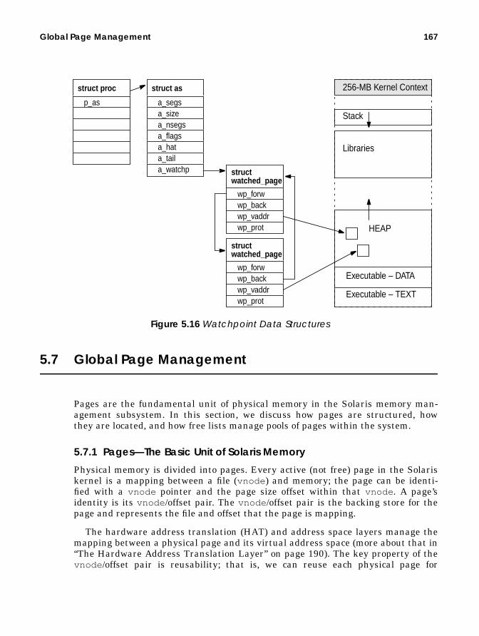
Global Page Management 167
Figure 5.16 Watchpoint Data Structures
5.7 Global Page Management
Pages are the fundamental unit of physical memory in the Solaris memory man-agement subsystem. In this section, we discuss how pages are structured, howthey are located, and how free lists manage pools of pages within the system.
5.7.1 Pages—The Basic Unit of Solaris Memory
Physical memory is divided into pages. Every active (not free) page in the Solariskernel is a mapping between a file (vnode ) and memory; the page can be identi-fied with a vnode pointer and the page size offset within that vnode . A page’sidentity is its vnode /offset pair. The vnode /offset pair is the backing store for thepage and represents the file and offset that the page is mapping.
The hardware address translation (HAT) and address space layers manage themapping between a physical page and its virtual address space (more about that in“The Hardware Address Translation Layer” on page 190). The key property of thevnode /offset pair is reusability; that is, we can reuse each physical page for
a_segs
struct as
a_sizea_nsegsa_flagsa_hata_tail
p_as
struct proc
a_watchp
wp_forw
struct
wp_backwp_vaddrwp_prot
watched_page
wp_forw
struct
wp_backwp_vaddrwp_prot
watched_page
Executable – TEXT
Executable – DATA
HEAP
Stack
Libraries
256-MB Kernel Context

168 Solaris Memory Architecture
another task by simply synchronizing its contents in RAM with its backing store(the vnode and offset) before the page is reused.
For example, we can reuse a page of heap memory from a process by simplycopying the contents to its vnode and offset, which in this case will copy the con-tents to the swap device. The same mechanism is used for caching files, and wesimply use the vnode /offset pair to reference the file that the page is caching. If wewere to reuse a page of memory that was caching a regular file, then we simplysynchronize the page with its backing store (if the page has been modified) or justreuse the page if it is not modified and does not need resyncing with its backingstore.
Figure 5.17 The Page Structure
5.7.2 The Page Hash List
The VM system hashes pages with identity (a valid vnode /offset pair) onto a glo-bal hash list so that they can be located by vnode and offset. Three page functionssearch the global page hash list: page_find() , page_lookup() , andpage_lookup_nowait() . These functions take a vnode and offset as argumentsand return a pointer to a page structure if found.
The global hash list is an array of pointers to linked lists of pages. The func-tions use a hash to index into the page_hash array to locate the list of pages thatcontains the page with the matching vnode /offset pair. Figure 5.18 shows how thepage_find() function indexes into the page_hash array to locate a page match-ing a given vnode /offset.
struct vnode
Vnode’s Page List
vnode offset
backing store
Free list or I/O List
Global Hash List
Flags to lock page in memory
v_pages
p_vnode
struct page
p_offsetp_hashp_vpnextp_vpprevp_nextp_prevp_lckcntp_cowcntp_selock

Global Page Management 169
page_find() locates a page as follows:
1. It calculates the slot in the page_hash array containing a list of potentialpages by using the PAGE_HASH_FUNC macro, shown below.
2. It uses the PAGE_HASH_SEARCH macro, shown below, to search the list ref-erenced by the slot for a page matching vnode /offset. The macro traversesthe linked list of pages until it finds such a page.
5.7.3 MMU-Specific Page Structures
The defined page structure is the same across different platforms and hence con-tains no machine-specific structures. We do, however, need to keep machine-spe-cific data about every page, for example, the HAT information that describes howthe page is mapped by the MMU. The kernel wraps the machine-independent pagestructure with a machine-specific page structure, struct machpage . The contents
#define PAGE_HASHSZ page_hashsz#define PAGE_HASHAVELEN 4#define PAGE_HASHVPSHIFT 6#define PAGE_HASH_FUNC(vp, off) \ ((((uintptr_t)(off) >> PAGESHIFT) + \ ((uintptr_t)(vp) >> PAGE_HASHVPSHIFT)) & \ (PAGE_HASHSZ - 1))
Header File <vm/page.h>
ine PAGE_HASH_SEARCH(index, pp, vp, off) { \ for ((pp) = page_hash[(index)]; (pp); (pp) = (pp)->p_hash) { \ if ((pp)->p_vnode == (vp) && (pp)->p_offset == (off)) \ break; \ } \
Header File <vm/page.h>
struct page * page_hash[]
page_find(vnode,offset) {
index = PAGE_HASH_FUNC(vnode,offset)
struct page
page = PAGE_HASH_SEARCH \(index, vnode, offset)
}
Figure 5.18 Locating Pages by Their Vnode/Offset Identity

170 Solaris Memory Architecture
of the machine-specific page structure are hidden from the generic kernel—onlythe HAT machine-specific layer can see or manipulate its contents. Figure 5.19shows how each page structure is embedded in a machine-dependent structmachpage .
The machine-specific page contains a pointer to the HAT-specific mapping informa-tion, and information about the page’s HAT state is stored in the machine-specificmachpage . The store information includes bits that indicate whether the page hasbeen referenced or modified, for use in the page scanner (covered later in the chap-ter). Both the machine-independent and machine-dependent page structures sharethe same start address in memory, so a pointer to a page structure can be cast to apointer to a machine-specific page structure (see Figure 5.19). Macros for convert-ing between machine-independent pages and machine-dependent page structuresmake the cast.
5.7.4 Physical Page Lists
The Solaris kernel uses a segmented global physical page list, consisting of seg-ments of contiguous physical memory. (Many hardware platforms now presentmemory in noncontiguous groups.) Contiguous physical memory segments areadded during system boot. They are also added and deleted dynamically when
p_paget
struct
p_mappingp_pagenump_nrmp_vcolorp_indexp_share
machpage
p_vnode
struct page
p_offsetp_hashp_vpnextp_vpprevp_nextp_prevp_lckcntp_cowcntp_selock
HAT information about this page’stranslation to physical memory
Software copies of page refer-ence and modified bits
Figure 5.19 Machine-Specific Page Structures: sun4u Example

Global Page Management 171
physical memory is added and removed while the system is running. Figure 5.20shows the arrangement of the physical page lists into contiguous segments.
5.7.4.1 Free List and Cache List
The free list and the cache list hold pages that are not mapped into any addressspace and that have been freed by page_free() . The sum of these lists isreported in the free column in vmstat . Even though vmstat reports these pagesas free, they can still contain a valid page from a vnode /offset and hence are stillpart of the global page cache. Pages that are caching files in the page cache canappear on the free list. Memory on the cache list is not really free, it is a validcache of a page from a file. The cache list exemplifies how the file systems usememory as a file system cache.
The free list contains pages that no longer have a vnode and offset associatedwith them—which can only occur if the page has been destroyed and removed froma vnode ’s hash list. The free list is generally very small, since most pages that areno longer used by a process or the kernel still keep their vnode /offset informationintact. Pages are put on the free list when a process exits, at which point all of theanonymous memory pages (heap, stack, and copy-on-write pages) are freed.
The cache list is a hashed list of pages that still have mappings to valid vnodeand offset. Recall that pages can be obtained from the cache list by the
struct memseg
Physical Page Listpagesepagespages_basepages_end
next
struct memseg
Physical Page Listpagesepagespages_basepages_end
next
memsegs
Figure 5.20 Contiguous Physical Memory Segments

172 Solaris Memory Architecture
page_lookup() routine. This function accepts a vnode and offset as the argu-ment and returns a page structure. If the page is found on the cache list, then thepage is removed from the cache list and returned to the caller. When we find andremove pages from the cache list, we are reclaiming a page. Page reclaims arereported by vmstat in the “re” column.
5.7.5 The Page-Level Interfaces
The Solaris virtual memory system implementation has grouped page manage-ment and manipulation into a central group of functions. These functions are usedby the segment drivers and file systems to create, delete, and modify pages. Themajor page-level interfaces are shown in Table 5-10.
Table 5-10 Solaris 7 Page Level Interfaces
Method Descriptionpage_create() Creates pages. Page coloring is based on a hash of
the vnode offset. page_create() is provided forbackward compatibility only. Don’t use it if you don’thave to. Instead, use the page_create_va() func-tion so that pages are correctly colored.
page_create_va() Creates pages, taking into account the virtualaddress they will be mapped to. The address is usedto calculate page coloring.
page_exists() Tests that a page for vnode /offset exists.page_find() Searches the hash list for a page with the specified
vnode and offset that is known to exist and isalready locked.
page_first() Finds the first page on the global page hash list.page_free() Frees a page. Pages with vnode /offset go onto the
cache list; other pages go onto the free list.page_isfree() Checks whether a page is on the free listpage_ismod() Checks whether a page is modified. This function
checks only the software bit in the page structure. Tosync the MMU bits with the page structure, you mayneed to call hat_pagesync() before callingpage_ismod() .
page_isref() Checks whether a page has been referenced; checksonly the software bit in the page structure. To syncthe MMU bits with the page structure, you may needto call hat_pagesync() before callingpage_isref() .
page_isshared() Checks whether a page is shared across more thanone address space.

Global Page Management 173
The page_create_va() function allocates pages. It takes the number of pages toallocate as an argument and returns a page list linked with the pages that havebeen taken from the free list. page_create_va() also takes a virtual address asan argument so that it can implement page coloring (discussed in Section 5.7.8,“Page Coloring,” on page 174). The new page_create_va() function subsumesthe older page_create() function and should be used by all newly developed sub-systems because page_create() may not correctly color the allocated pages.
5.7.6 The Page Throttle
Solaris implements a page creation throttle so a small core of memory is availablefor consumption by critical parts of the kernel. The page throttle, implemented inthe page_create() and page_create_va() functions, causes page creates toblock when the PG_WAITflag is specified, that is, when available is less than thesystem global, throttlefree . By default, the system global parameter, throt-tlefree , is set to the same value as the system global parameter minfree . Bydefault, memory allocated through the kernel memory allocator specifies PG_WAITand is subject to the page-created throttle. (See Section 6.2, “Kernel Memory Allo-cation,” on page 212 for more information on kernel memory allocation.)
5.7.7 Page Sizes
The Solaris kernel uses a fundamental page size that varies according to theunderlying hardware. On UltraSPARC and beyond, the fundamental page size is 8Kbytes. The hardware on which Solaris runs has several different types of mem-ory management units, which support a variety of page sizes, as listed in Table5-11.
page_lookup() Finds a page representing the specified vnode /offset.If the page is found on a free list, then it will beremoved from the free list.
page_lookup_nowait() Finds a page representing the specified vnode /offsetthat is not locked or on the free list.
page_needfree() Informs the VM system we need some pages freedup. Calls to page_needfree () must be symmetric,that is they must be followed by anotherpage_needfree () with the same amount of memorymultiplied by -1,after the task is complete.
page_next() Finds the next page on the global page hash list.
Table 5-10 Solaris 7 Page Level Interfaces (Continued)
Method Description

174 Solaris Memory Architecture
The optimal MMU page size is a trade-off between performance and memory sizeefficiency. A larger page size has less memory management overhead and hencebetter performance, but a smaller page size wastes less memory (memory iswasted when a page is not completely filled). (See “Large Pages” on page 200 forfurther information on large pages.)
5.7.8 Page Coloring
Some interesting effects result from the organization of pages within the proces-sor caches, and as a result, the page placement policy within these caches can dra-matically affect processor performance. When pages overlay other pages in thecache, they can displace cache data that we might not want overlaid, resulting inless cache utilization and “hot spots.”
The optimal placement of pages in the cache often depends on the memoryaccess patterns of the application; that is, is the application accessing memory in arandom order, or is it doing some sort of strided ordered access? Several differentalgorithms can be selected in the Solaris kernel to implement page placement; thedefault attempts to provide the best overall performance.
To understand how page placement can affect performance, let’s look at thecache configuration and see when page overlaying and displacement can occur. TheUltraSPARC-I and -II implementations use virtually addressed L1 caches andphysically addressed L2 caches. The L2 cache is arranged in lines of 64 bytes, andtransfers are done to and from physical memory in 64-byte units. Figure 5.27 onpage 194 shows the architecture of the UltraSPARC-I and -II CPU modules withtheir caches. The L1 cache is 16 Kbytes, and the L2 (external) cache can varybetween 512 Kbytes and 8 Mbytes. We can query the operating system with adb tosee the size of the caches reported to the operating system. The L1 cache sizes are
Table 5-11 Page Sizes on Different Sun Platforms
System Type SystemType
MMU PageSize
Capability
Solaris 2.xPage Size
Early SPARC systems sun4c 4K 4KmicroSPARC-I, -II sun4m 4K 4KSuperSPARC-I, -II sun4m 4K, 4M 4K, 4MUltraSPARC-I, -II sun4u 4K, 64K, 512K, 4M 8K, 4MIntel x86 architecture i86pc 4K, 4M 4K, 4M

Global Page Management 175
recorded in the vac_size parameter, and the L2 cache size is recorded in theecache_size parameter.
We’ll start by using the L2 cache as an example of how page placement can affectperformance. The physical addressing of the L2 cache means that the cache isorganized in page-sized multiples of the physical address space, which means thatthe cache effectively has only a limited number of page-aligned slots. The numberof effective page slots in the cache is the cache size divided by the page size. Tosimplify our examples, let’s assume we have a 32-Kbyte L2 cache (much smallerthan reality), which means that if we have a page size of 8 Kbytes, there are fourpage-sized slots on the L2 cache. The cache does not necessarily read and write8-Kbyte units from memory; it does that in 64-byte chunks, so in reality our32-Kbyte cache has 1024 addressable slots. Figure 5.21 shows how our cachewould look if we laid it out linearly.
Figure 5.21 Physical Page Mapping into a 64-Kbyte Physical Cache
The L2 cache is direct-mapped from physical memory. If we were to access physi-cal addresses on a 32-Kbyte boundary, for example, offsets 0 and 32678, then bothmemory locations would map to the same cache line. If we were now to accessthese two addresses, we cause the cache lines for the offset 0 address to be read,then flushed (cleared), the cache line for the offset 32768 address to be read in, andthen flushed, then the first reloaded, etc. This ping-pong effect in the cache isknown as cache flushing (or cache ping-ponging), and it effectively reduces our per-formance to that of real-memory speed, rather than cache speed. By accessing
# adb -kphysmem 7a97vac_size/Dvac_size:vac_size: 16384ecache_size/Decache_size:ecache_size: 1048576
0 8k 16k 24k
0 8k 16k 24k32k 40k 48k 56k64k 72k 80k 88k
64-byteCacheLine
Physical Address Offset Mapping
eCache Offset

176 Solaris Memory Architecture
memory on our 32-Kbyte cache-size boundary, we have effectively used only 64bytes of the cache (a cache line size), rather than the full cache size. Memory isoften up to 10–20 times slower than cache and so can have a dramatic effect onperformance.
Our simple example was based on the assumption that we were accessing physi-cal memory in a regular pattern, but we don’t program to physical memory; rather,we program to virtual memory. Therefore, the operating system must provide asensible mapping between virtual memory and physical memory; otherwise, effectssuch as our example can occur.
By default, physical pages are assigned to an address space from the order inwhich they appear in the free list. In general, the first time a machine boots, thefree list may have physical memory in a linear order, and we may end up with thebehavior described in our “ping pong” example. Once a machine has been running,the physical page free list will become randomly ordered, and subsequent reruns ofan identical application could get very different physical page placement and, as aresult, very different performance. On early Solaris implementations, this isexactly what customers saw—differing performance for identical runs, as much as30 percent difference.
To provide better and consistent performance, the Solaris kernel uses a page col-oring algorithm when pages are allocated to a virtual address space. Rather thanbeing randomly allocated, the pages are allocated with a specific predeterminedrelationship between the virtual address to which they are being mapped and theirunderlying physical address. The virtual-to-physical relationship is predeter-mined as follows: the free list of physical pages is organized into specifically col-ored bins, one color bin for each slot in the physical cache; the number of color binsis determined by the ecache size divided by the page size. (In our example, therewould be exactly four colored bins.)
When a page is put on the free list, the page_free () algorithms assign it to acolor bin. When a page is consumed from the free list, the virtual-to-physical algo-rithm takes the page from a physical color bin, chosen as a function of the virtualaddress which to which the page will be mapped. The algorithm requires thatwhen allocating pages from the free list, the page create function must know thevirtual address to which a page will be mapped.
New pages are allocated by calling the page_create_va() function. Thepage_create_va () function accepts the virtual address of the location that thepage is going to be mapped as an argument; then, the virtual-to-physical color binalgorithm can decide which color bin to take physical pages from. The

Global Page Management 177
page_create_va () function is described with the page management functions inTable 5-10 on page 204.
No one algorithm suits all applications because different applications have differ-ent memory access patterns. Over time, the page coloring algorithms used in theSolaris kernel have been refined as a result of extensive simulation, benchmarks,and customer feedback. The kernel supports a default algorithm and two optionalalgorithms. The default algorithm was chosen according to the following criteria:
• Fairly consistent, repeatable results• Good overall performance for the majority of applications• Acceptable performance across a wide range of applications
The default algorithm uses a hashing algorithm to distribute pages as evenly aspossible throughout the cache. The default and three other available page coloringalgorithms are shown in Table 5-12.
Note: The page_create_va() function deprecates the older page_create()function. We chose to add a new function rather than adding an additionalargument the existing page_create() function so that existing third party load-able kernel modules which call page_create() remain functional. However,because page_create() does not know about virtual addresses, it has to picka color at random - which can cause significant performance degredation. Thepage_create_va() function should always be used for new code.
Table 5-12 Solaris Page Coloring Algorithms
Algorithm Description Solaris Availability
No. Name 2.5.1 2.6 70 Hashed VA The physical page color bin
is chosen on a hashed algo-rithm to ensure even distri-bution of virtual addressesacross the cache.
Default Default Default
1 P. Addr =V. Addr
The physical page color ischosen so that physicaladdresses map directly tothe virtual addresses (as inour example).
Yes Yes Yes
2 Bin Hop-ping
Physical pages are allo-cated with a round-robinmethod.
Yes Yes Yes

178 Solaris Memory Architecture
The Ultra Enterprise 10000 has a different default algorithm, which tries toevenly distribute colors for each process’s address space so that no one color ismore used than another. This algorithm is correct most of the time, but in somecases, the hashed or direct (0 or 1) algorithms can be better.
You can change the default algorithm by setting the system parameterconsistent_coloring , either on-the-fly with adb or permanently in /etc/sys-tem .
So, which algorithm is best? Well, your mileage will vary, depending on your appli-cation. Page coloring usually only makes a difference on memory-intensive scien-tific applications, and the defaults are usually fine for commercial or databasesystems. If you have a time-critical scientific application, then we recommend thatyou experiment with the different algorithms and see which is best. Rememberthat some algorithms will produce different results for each run, so aggregate asmany runs as possible.
5.8 The Page Scanner
The page scanner is the memory management daemon that manages systemwidephysical memory. The page scanner and the virtual memory page fault mecha-nism are the core of the demand-paged memory allocation system used to manageSolaris memory. When there is a memory shortage, the page scanner runs, to stealmemory from address spaces by taking pages that haven’t been used recently,syncing them up with their backing store (swap space if they are anonymouspages), and freeing them. If paged-out virtual memory is required again by an
6 Kessler’sBest Bin
Kessler best bin algorithm.Keeps history per process ofused colors and choosesleast used color; if multi-ple, use largest bin.
E10000Only(Default)
E10000Only(Default)
NotAvailable
# adb -kwphysmem 7a97consistent_coloring/Dconsistent_coloring:consistent_coloring: 0consistent_coloring/W 1consistent_coloring: 0x0 = 0x1
Table 5-12 Solaris Page Coloring Algorithms
Algorithm Description Solaris Availability
No. Name 2.5.1 2.6 7

The Page Scanner 179
address space, then a memory page fault occurs when the virtual address is refer-enced and the pages are recreated and copied back from their backing store.
The balancing of page stealing and page faults determines which parts of vir-tual memory will be backed by real physical memory and which will be moved outto swap. The page scanner does not understand the memory usage patterns orworking sets of processes; it only knows reference information on a physicalpage-by-page basis. This policy is often referred to as global page replacement; thealternative process-based page management, is known as local page replacement.
The subtleties of which pages are stolen govern the memory allocation policiesand can affect different workloads in different ways. During the life of the Solariskernel, only two significant changes in memory replacement policies haveoccurred:
• Enhancements to minimize page stealing from extensively shared librariesand executables
• Priority paging to prevent application, shared library, and executable pagingon systems with ample memory
We discuss these changes in more detail when we describe page scanner imple-mentation.
5.8.1 Page Scanner Operation
The page scanner tracks page usage by reading a per-page hardware bit from thehardware MMU for each page. Two bits are kept for each page; they indicatewhether the page has been modified or referenced since the bits were last cleared.The page scanner uses the bits as the fundamental data to decide which pages ofmemory have been used recently and which have not.
The page scanner is a kernel thread, which is awakened when the amount ofmemory on the free-page list falls below a system threshhold, typically 1/64th oftotal physical memory. The page scanner scans through pages in physical pageorder, looking for pages that haven’t been used recently to page out to the swapdevice and free. The algorithm that determines whether pages have been usedresembles a clock face and is known as the two-handed clock algorithm. This algo-rithm views the entire physical page list as a circular list, where the last physical
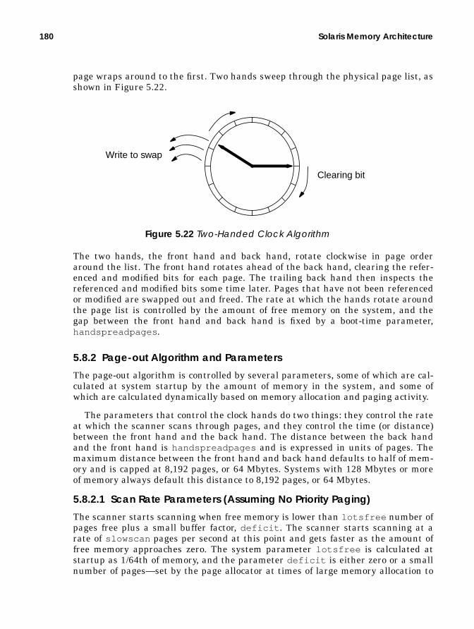
180 Solaris Memory Architecture
page wraps around to the first. Two hands sweep through the physical page list, asshown in Figure 5.22.
Figure 5.22 Two-Handed Clock Algorithm
The two hands, the front hand and back hand, rotate clockwise in page orderaround the list. The front hand rotates ahead of the back hand, clearing the refer-enced and modified bits for each page. The trailing back hand then inspects thereferenced and modified bits some time later. Pages that have not been referencedor modified are swapped out and freed. The rate at which the hands rotate aroundthe page list is controlled by the amount of free memory on the system, and thegap between the front hand and back hand is fixed by a boot-time parameter,handspreadpages .
5.8.2 Page-out Algorithm and Parameters
The page-out algorithm is controlled by several parameters, some of which are cal-culated at system startup by the amount of memory in the system, and some ofwhich are calculated dynamically based on memory allocation and paging activity.
The parameters that control the clock hands do two things: they control the rateat which the scanner scans through pages, and they control the time (or distance)between the front hand and the back hand. The distance between the back handand the front hand is handspreadpages and is expressed in units of pages. Themaximum distance between the front hand and back hand defaults to half of mem-ory and is capped at 8,192 pages, or 64 Mbytes. Systems with 128 Mbytes or moreof memory always default this distance to 8,192 pages, or 64 Mbytes.
5.8.2.1 Scan Rate Parameters (Assuming No Priority Paging)
The scanner starts scanning when free memory is lower than lotsfree number ofpages free plus a small buffer factor, deficit . The scanner starts scanning at arate of slowscan pages per second at this point and gets faster as the amount offree memory approaches zero. The system parameter lotsfree is calculated atstartup as 1/64th of memory, and the parameter deficit is either zero or a smallnumber of pages—set by the page allocator at times of large memory allocation to
Clearing bit
Write to swap

The Page Scanner 181
let the scanner free a few more pages above lotsfree in anticipation of morememory requests.
Figure 5.23 shows the rate at which the scanner scans increases linearly as freememory ranges between lotsfree and zero. The scanner starts scanning at theminimum rate set by slowscan when memory falls below lotsfree and thenincreases to fastscan if memory falls low enough.
The number of pages scanned increases from the slowest rate (set by slowscanwhen lotsfree pages are free) to a maximum determined by the system parame-ter fastscan . Free memory never actually reaches zero, but for simplicity thealgorithm calculates the maximum interpolated rate against the free memoryranging between lotsfree and zero. In our example system with 1 Gbyte of phys-ical memory (shown in Figure 5.24 on page 185), we can see that the scannerstarts scanning when free memory falls to 16 Mbytes plus the short-term memorydeficit.
slow-
fast-
lotsfreeminfreethrottle-
free
Sca
n R
ate
lotsfree+deficit
desfree
8192
100
4 M
B
4 M
B
8 M
B
16 M
B
(1GB Example)
scan
scan
0 M
B
0
Amount of Free Memory
Num
ber
of
Pag
es S
cann
ed P
er S
econ
d
Figure 5.23 Page Scanner Rate, Interpolated by Number of Free Pages

182 Solaris Memory Architecture
For this example, we’ll assume that the deficit is zero. When free memory fallsto 16 Mbytes, the scanner will wake up and start examining 100 pages per second,according to the system parameter slowscan . The slowscan parameter is 100 bydefault on Solaris systems, and fastscan is set to total , cappedat 8192 pages per second. If free memory falls to 12 Mbytes (1536 pages), the scan-ner scans at a higher rate, according to the page scanner interpolation shown inthe following equation:
If we convert free memory and lotsfree to numbers of pages (free memory of 12Mbytes is 1536 pages, and lotsfree is set to 16 Mbytes, or 2048 pages), then wescan at 2123 pages per second.
By default, the scanner is run four times per second when there is a memory short-age. If the amount of free memory falls below the system parameter desfree , thescanner is run at every clock cycle or, by default, 100 times a second. This schemehelps the scanner try to keep at least desfree pages on the free list.
5.8.2.2 Not Recently Used Time
The time between the front hand and back hand varies according to the number ofpages between the front hand and back hand and the rate at which the scanner isscanning. The time between the front hand clearing the reference bit and the backhand checking the reference bit is a significant factor that affects the behavior ofthe scanner because it controls the amount of time that a page can be left alonebefore it is potentially stolen by the page scanner. A short time between the refer-ence bit being cleared and checked means that all but the most active pagesremain intact; a long time means that only the largely unused pages are stolen.The ideal behavior is the latter because we want only the least recently used pagesstolen, which means we want a long time between the front and back hands.
The time between clearing and checking of the reference bit can vary from just afew seconds to several hours, depending on the scan rate. The scan rate on today’sbusy systems can often grow to several thousand, which means that a very smalltime exists between the front hand and back hand. For example, a system with ascan rate of 2,000 pages per second and the default hand spread of 8,192 pages hasa clear/check time of only 4 seconds. High scan rates are quite normal on systemsbecause of the memory pressure induced by the file system. (We discuss this topicfurther in “Is All That Paging Bad for My System?” on page 608.)
physicalmemory2⁄
scanratelotsfree freememory–
lotsfree----------------------------------------------------------- fastscan×
= slowscanfreememlotsfree-----------------------×
+
scanrate2048 1536–
2048------------------------------ 8192×
= 10015362048------------×
2123=+

The Page Scanner 183
5.8.3 Shared Library Optimizations
A subtle optimization added to the page scanner prevents it from stealing pagesfrom extensively shared libraries. The page scanner looks at the share referencecount for each page; if the page is shared more than a certain amount, then it isskipped during the page scan operation. An internal parameter, po_share , setsthe threshold for the amount of shares a page can have before it is skipped. If thepage has more than po_share mappings (i.e., it’s shared by more than po_shareprocesses), then it is skipped. By default, po_share starts at 8; each time around,it is decremented unless the scan around the clock does not find any page to free,in which case po_share is incremented. The po_share parameter can floatbetween 8 and 134217728.
5.8.4 The Priority Paging Algorithm
Solaris 7 shipped with a new optional paging algorithm—a page-stealing algo-rithm that results in much better system response and throughput for systemsmaking use of the file systems. The algorithm is also available on older Solarisreleases (from 2.5.1 onwards) with the addition of a kernel patch. You enable thenew algorithm by setting the priority_paging variable to 1 in /etc/system .
The new algorithm was introduced to overcome adverse behavior that results fromthe memory pressure caused by the file system. Back in SunOS 4.0, when the vir-tual memory system was rewritten, the file system cache and virtual memory sys-tem were integrated to allow the entire memory system to be used as a file systemcache; that is, the file system uses pages of memory from the free memory pool,just as do processes when they request memory.
The demand paging algorithm allows the file system cache to grow and shrinkdynamically as required, by stealing pages which have not been recently used byother subsystems. However, back when this work was done, the memory pressurefrom the file system was relatively low, as were the memory requests from the pro-cesses on the system. Both were in the order of tens to hundreds of pages per sec-ond, so memory allocation could be based on who was using the pages the most.When processes accessed their memory pages frequently, the scanner was biasedto steal from the file system, and the file system cache would shrink accordingly.
Today, systems are capable of sustaining much higher I/O rates, which meansthat the file system can put enormous memory pressure on the memory system—so much so that the amount of memory pressure from the file system can com-pletely destroy application performance by causing the page scanner to steal manyprocess pages.
** Enable the Priority Paging Algorithm*set priority_paging = 1

184 Solaris Memory Architecture
We like to think of the early SunOS 4.0 case as being like a finely balanced setof scales, where the process and file system requests sit on each side of the scaleand are reasonably balanced. But on today’s system, the scales are completelyweighted on the file system side because of the enormous paging rates required todo I/O through the file system. For example, even a small system can do 20 mega-bytes of I/O per second, which causes the file system to use 2,560 pages per sec-ond. To keep up with this request, the scanner must scan at least at this rate,usually higher because the scanner will not steal every page it finds. This typi-cally means a scan rate of 3,000 or higher, just to do some regular I/O.
As we saw earlier, when we scan at this rate, we have as little as a few secondsbetween the time we clear and the time we check for activity. As a result, we stealprocess memory that hasn’t been used in the last few seconds. The noticeable effectis that everything appears to grind to a halt when we start using the file systemfor significant I/O and free memory falls below lotsfree . It is important to notethat this effect can result even with ample memory in the system—adding morememory doesn’t make the situation any better.
To overcome this effect, the page scanner has a new algorithm that puts ahigher priority on a process’s pages, namely, its heap, stack, shared libraries, andexecutables. The algorithm permits the scanner to pick file system cache pagesonly when ample memory is available and hence only steal application pages whenthere is a true memory shortage.
The new algorithm introduces a new paging parameter, cachefree . When theamount of free memory lies between cachefree and lotsfree , the page scannersteals only file system cache pages. The scanner also now wakes up when memoryfalls below cachefree rather than below lotsfree , and the scan rate algorithmis changed accordingly.
scanratecachefree freememory–
cachefree---------------------------------------------------------------- fastscan×
= slowscanfreemem
cachefree--------------------------×
+

The Page Scanner 185
The scan rate is now interpolated between cachefree and zero, rather thanbetween lotsfree and zero, as shown in Figure 5.24.
Figure 5.24 Scan Rate Interpolation with the Priority Paging Algorithm
The algorithm pages only against the file system cache when memory is betweencachefree and lotsfree by skipping pages that are associated with the swapdevice (heap, stack, copy-on-write pages) and by skipping file pages that aremapped into an address space with execute permission (binaries, shared libraries).
The new algorithm has no side effects and should always be enabled on Solarisversions up to Solaris 7. (Note: The algorithm has been replaced in Solaris 8 by anew cache architecture, and priority paging should not be enabled on Solaris 8.) Itwas not enabled by default in Solaris 7 only because it was introduced very late inthe Solaris release cycle.
5.8.4.1 Page Scanner CPU Utilization Clamp
A CPU utilization clamp on the scan rate prevents the page-out daemon fromusing too much processor time. Two internal limits govern the desired and maxi-mum CPU time that the scanner should use. Two parameters, min_percent_cpuand max_percent_cpu , govern the amount of CPU that the scanner can use. Likethe scan rate, the actual amount of CPU that can be used at any given time isinterpolated by the amount of free memory. It ranges from min_percent_cpu
slow-
fast-
lotsfree cachefreeminfreethrottle-free
Sca
n R
ate
cachefree+deficit
desfree
8192
100
4 M
B
4 M
B
8 M
B
16 M
B
32 M
B
(1GB Example)
scan
scan
0 M
B
0
Amount of Free Memory
Num
ber
of
Pag
es S
cann
ed P
er S
econ
d

186 Solaris Memory Architecture
when free memory is at lotsfree (cachefree with priority paging enabled) tomax_percent_cpu if free memory were to fall to zero. The defaults formin_percent_cpu and max_percent_cpu are 4% and 80% of a single CPU,respectively (the scanner is single threaded).
5.8.4.2 Parameters That Limit Pages Paged Out
Another parameter, maxpgio , limits the rate at which I/O is queued to the swapdevices. It is set low to prevent saturation of the swap devices. The parameterdefaults to 40 I/Os per second on sun4c, sun4m, and sun4u architectures and to 60I/Os per second on the sun4d architecture. The default setting is often inadequatefor modern systems and should be set to 100 times the number of swap spindles.
Because the page-out daemon also pages out dirty file system pages that it findsduring scanning, this parameter can also indirectly limit file system throughput.File system I/O requests are normally queued and written by user processes andhence are not subject to maxpgio . However, when a lot of file system write activityis going on and many dirty file system pages are in memory, the page-out scannertrips over these and queues these I/Os; as a result, the maxpgio limit can some-times affect file system write throughput. Please refer to the memory parameterappendix for further recommendations.
5.8.4.3 Summary of Page Scanner Parameters
Table 5-13 describes the parameters that control the page-out process in the cur-rent Solaris and patch releases.
Table 5-13 Page Scanner Parameters
Parameter Description Min 2.7 Defaultcachefree If free memory falls below cache-
free , then the page-out scannerstarts 4 times/second, at a rate ofslowscan pages/second. Only filesystem pages are stolen and freed.
The cachefree parameter is setindirectly by the priority_pagingparameter. Whenpriority_paging is set to 1,cachefree is automatically set attwice the value of lotsfree duringboot.
lots-free
lotsfreeor2 x lotsfree(with pp.)
lotsfree The scanner starts stealing anony-mous memory pages when freememory falls below lotsfree .
512K 1/64th of mem-ory

The Page Scanner 187
5.8.5 Page Scanner Implementation
The page scanner is implemented as two kernel threads, both of which use processnumber 2, “pageout.” One thread scans pages, and the other thread pushes thedirty pages queued for I/O to the swap device. In addition, the kernel callout mech-anism wakes the page scanner thread when memory is insufficient. (The kernelcallout scheduling mechanism is discussed in detail in Section 2.5, “The KernelCallout Table,” on page 47.)
The scanner schedpaging() function is called four times per second by a call-out placed in the callout table. The schedpaging() function checks whether freememory is below the threshold (lotsfree or cachefree ) and, if required, pre-pares to trigger the scanner thread. The page scanner is not only awakened by thecallout thread, it is also triggered by the clock() thread if memory falls belowminfree or by the page allocator if memory falls below throttlefree .
desfree If free memory falls below des-free , then the page-out scanner isstarted 100 times/second.
min-free
lotsfree/2
minfree If free memory falls below min-free , then the page scanner is sig-naled to start every time a new pageis created.
desfree/2
throttlefree The number at which point thepage_create routines make thecaller wait until free pages areavailable.
— minfree
fastscan The rate of pages scanned per sec-ond when free memory = minfree .Measured in pages.
slow-scan
Minimum of 64MB/s or1/2 memorysize
slowscan The rate of pages scanned per sec-ond when free memory = lotsfree .
— 100
maxpgio A throttle for the maximum num-ber of pages per second that theswap device can handle.
~60 60 or 90pages/s
hand-spreadpages
The number of pages between thefront hand clearing the reference bitand the back hand checking the ref-erence bit.
1 fastscan
Table 5-13 Page Scanner Parameters (Continued)
Parameter Description Min 2.7 Default
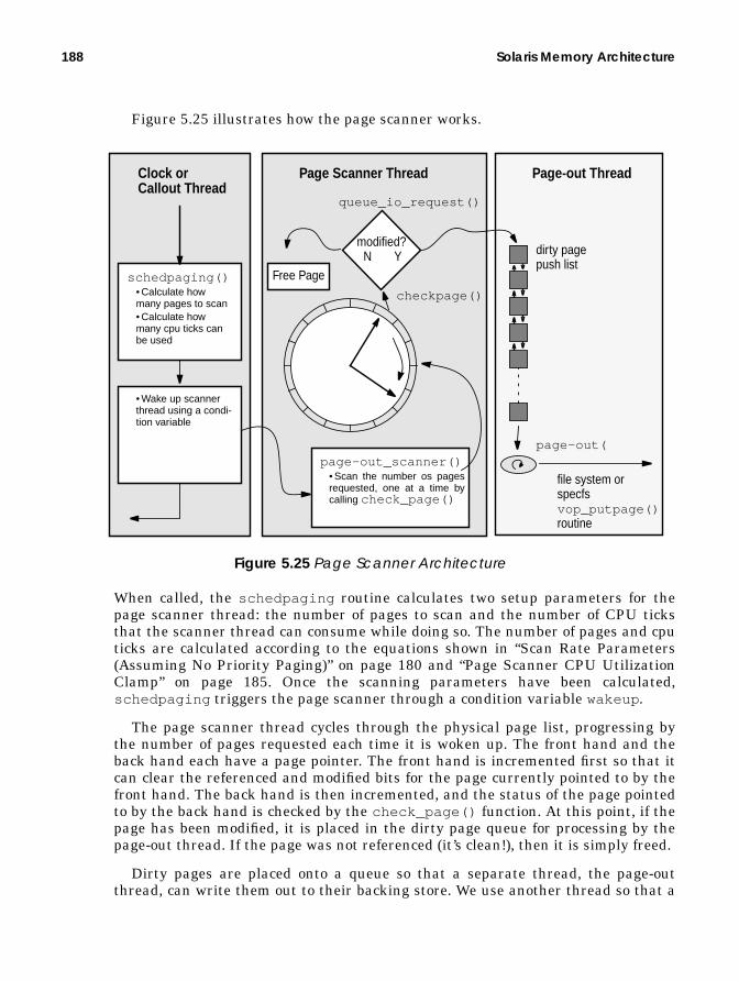
188 Solaris Memory Architecture
Figure 5.25 illustrates how the page scanner works.
Figure 5.25 Page Scanner Architecture
When called, the schedpaging routine calculates two setup parameters for thepage scanner thread: the number of pages to scan and the number of CPU ticksthat the scanner thread can consume while doing so. The number of pages and cputicks are calculated according to the equations shown in “Scan Rate Parameters(Assuming No Priority Paging)” on page 180 and “Page Scanner CPU UtilizationClamp” on page 185. Once the scanning parameters have been calculated,schedpaging triggers the page scanner through a condition variable wakeup .
The page scanner thread cycles through the physical page list, progressing bythe number of pages requested each time it is woken up. The front hand and theback hand each have a page pointer. The front hand is incremented first so that itcan clear the referenced and modified bits for the page currently pointed to by thefront hand. The back hand is then incremented, and the status of the page pointedto by the back hand is checked by the check_page() function. At this point, if thepage has been modified, it is placed in the dirty page queue for processing by thepage-out thread. If the page was not referenced (it’s clean!), then it is simply freed.
Dirty pages are placed onto a queue so that a separate thread, the page-outthread, can write them out to their backing store. We use another thread so that a
dirty page
file system orspecfsvop_putpage()routine
Page-out ThreadPage Scanner ThreadClock or
• Wake up scannerthread using a condi-tion variable
schedpaging()• Calculate howmany pages to scan• Calculate howmany cpu ticks canbe used
page-out_scanner()• Scan the number os pagesrequested, one at a time bycalling check_page()
checkpage()
queue_io_request()
page-out(
push list
Callout Thread
Free Page
modified?N Y
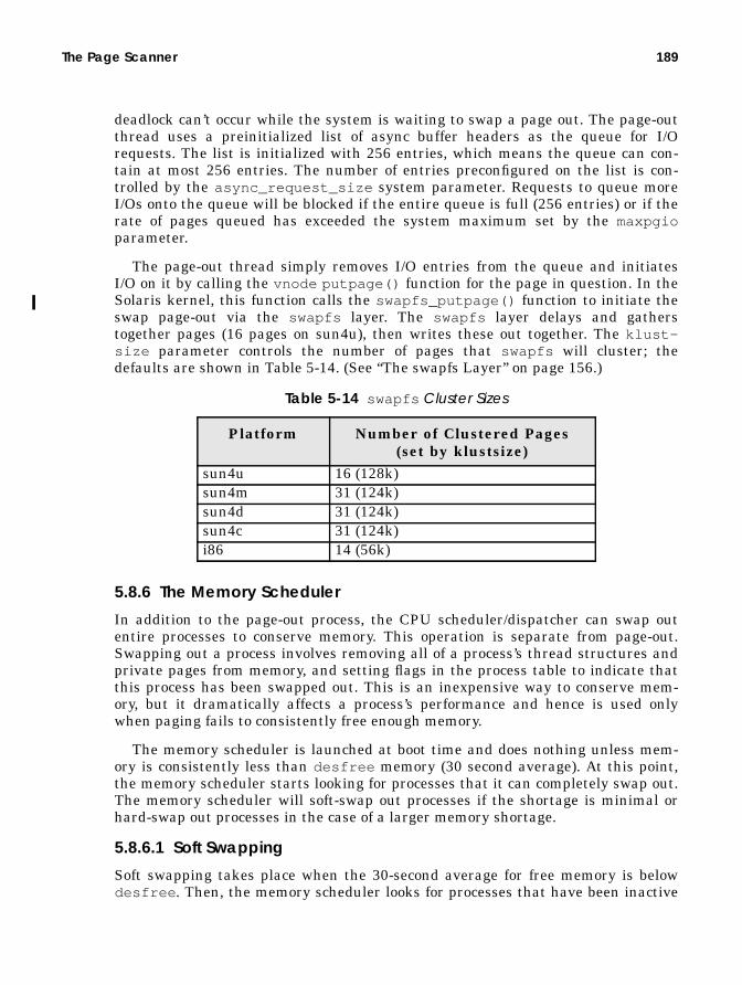
The Page Scanner 189
deadlock can’t occur while the system is waiting to swap a page out. The page-outthread uses a preinitialized list of async buffer headers as the queue for I/Orequests. The list is initialized with 256 entries, which means the queue can con-tain at most 256 entries. The number of entries preconfigured on the list is con-trolled by the async_request_size system parameter. Requests to queue moreI/Os onto the queue will be blocked if the entire queue is full (256 entries) or if therate of pages queued has exceeded the system maximum set by the maxpgioparameter.
The page-out thread simply removes I/O entries from the queue and initiatesI/O on it by calling the vnode putpage() function for the page in question. In theSolaris kernel, this function calls the swapfs_putpage() function to initiate theswap page-out via the swapfs layer. The swapfs layer delays and gatherstogether pages (16 pages on sun4u), then writes these out together. The klust-size parameter controls the number of pages that swapfs will cluster; thedefaults are shown in Table 5-14. (See “The swapfs Layer” on page 156.)
5.8.6 The Memory Scheduler
In addition to the page-out process, the CPU scheduler/dispatcher can swap outentire processes to conserve memory. This operation is separate from page-out.Swapping out a process involves removing all of a process’s thread structures andprivate pages from memory, and setting flags in the process table to indicate thatthis process has been swapped out. This is an inexpensive way to conserve mem-ory, but it dramatically affects a process’s performance and hence is used onlywhen paging fails to consistently free enough memory.
The memory scheduler is launched at boot time and does nothing unless mem-ory is consistently less than desfree memory (30 second average). At this point,the memory scheduler starts looking for processes that it can completely swap out.The memory scheduler will soft-swap out processes if the shortage is minimal orhard-swap out processes in the case of a larger memory shortage.
5.8.6.1 Soft Swapping
Soft swapping takes place when the 30-second average for free memory is belowdesfree . Then, the memory scheduler looks for processes that have been inactive
Table 5-14 swapfs Cluster Sizes
Platform Number of Clustered Pages(set by klustsize)
sun4u 16 (128k)sun4m 31 (124k)sun4d 31 (124k)sun4c 31 (124k)i86 14 (56k)

190 Solaris Memory Architecture
for at least maxslp seconds. When the memory scheduler find a process that hasbeen sleeping for maxslp seconds, it swaps out the thread structures for eachthread, then pages out all of the private pages of memory for that process.
5.8.6.2 Hard Swapping
Hard swapping takes place when all of the following are true:
• At least two processes are on the run queue, waiting for CPU.• The average free memory over 30 seconds is consistently less than desfree .• Excessive paging (determined to be true if page-out + page-in > maxpgio ) is
going on.
When hard swapping is invoked, a much more aggressive approach is used to findmemory. First, the kernel is requested to unload all modules and cache memorythat are not currently active, then processes are sequentially swapped out untilthe desired amount of free memory is returned. Parameters that affect the Mem-ory Scheduler are shown in Table 5-15.
5.9 The Hardware Address Translation Layer
The hardware address translation (HAT) layer controls the hardware that man-ages mapping of virtual to physical memory. The HAT layer provides interfacesthat implement the creation and destruction of mappings between virtual andphysical memory and provides a set of interfaces to probe and control the MMU.The HAT layer also implements all of the low-level trap handlers to manage pagefaults and memory exceptions. Figure 5.26 shows the logical demarcation betweenelements of the HAT layer.
Figure 5.26 Role of the HAT Layer in Virtual-to-Physical Translation
Table 5-15 Memory Scheduler Parameters
Parameter Affect on Memory Schedulerdesfree If the average amount of free memory falls below des-
free for 30 seconds, then the memory scheduler isinvoked.
maxslp When soft-swapping, the memory scheduler starts swap-ping processes that have slept for at least maxslp sec-onds. The default for maxslp is 20 seconds and is tunable.
maxpgio When the run queue is greater than 2, free memory isbelow desfree , and the paging rate is greater than maxp-gio , then hard swapping occurs, unloading kernel mod-ules and process memory.
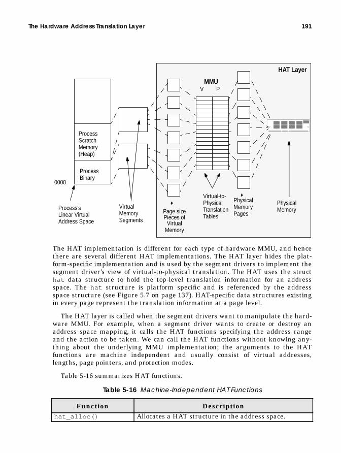
The Hardware Address Translation Layer 191
The HAT implementation is different for each type of hardware MMU, and hencethere are several different HAT implementations. The HAT layer hides the plat-form-specific implementation and is used by the segment drivers to implement thesegment driver’s view of virtual-to-physical translation. The HAT uses the structhat data structure to hold the top-level translation information for an addressspace. The hat structure is platform specific and is referenced by the addressspace structure (see Figure 5.7 on page 137). HAT-specific data structures existingin every page represent the translation information at a page level.
The HAT layer is called when the segment drivers want to manipulate the hard-ware MMU. For example, when a segment driver wants to create or destroy anaddress space mapping, it calls the HAT functions specifying the address rangeand the action to be taken. We can call the HAT functions without knowing any-thing about the underlying MMU implementation; the arguments to the HATfunctions are machine independent and usually consist of virtual addresses,lengths, page pointers, and protection modes.
Table 5-16 summarizes HAT functions.
Table 5-16 Machine-Independent HAT Functions
Function Descriptionhat_alloc() Allocates a HAT structure in the address space.
HAT Layer
V P
0000
ProcessBinary
ProcessScratchMemory
Process’sLinear VirtualAddress Space
VirtualMemorySegments Virtual
Memory
MMU
Virtual-to-PhysicalTranslationTables
PhysicalMemory
(Heap)
PhysicalMemoryPagesPage size
Pieces of

192 Solaris Memory Architecture
5.9.1 Virtual Memory Contexts and Address Spaces
A virtual memory context is a set of virtual-to-physical translations that maps anaddress space. We change virtual memory contexts when the scheduler wants toswitch execution from one process to another or when a trap or interrupt from usermode to kernel occurs. The Solaris kernel always uses virtual memory context zeroto indicate the kernel context. The machine-specific HAT layer implements func-tions required to create, delete, and switch virtual memory contexts. Differenthardware MMUs support different numbers of concurrent virtual memory con-texts.
When the number of concurrent address spaces (processes) exceeds the numberof concurrent contexts supported by the hardware, the kernel has to steal contextsfrom peer processes at the time of context switch. Stealing contexts from otheraddress spaces has an indirect effect on performance. However, this issue was onlya concern on older systems such as the SPARCstation 1 and 2.
hat_chgattr() Changes the protections for the supplied virtualaddress range.
hat_clrattr() Clears the protections for the supplied virtual addressrange.
hat_free_end() Informs the HAT layer that a process has exited.hat_free_start() Informs the HAT layer that a process is exiting.hat_get_mapped_size() Returns the number of bytes that have valid mappings.hat_getattr() Gets the protections for the supplied virtual address
range.hat_memload() Creates a mapping for the supplied page at the sup-
plied virtual address. Used to create mappings.hat_setattr() Sets the protections for the supplied virtual address
range.hat_stats_disable() Finishes collecting stats on an address space.hat_stats_enable() Starts collecting page reference and modification stats
on an address space.hat_swapin() Allocates resources for a process that is about to be
swapped in.hat_swapout() Allocates resources for a process that is about to be
swapped out.hat_sync() Synchronizes the struct_page software referenced
and modified bits with the hardware MMU.hat_unload() Unloads a mapping for the given page at the given
address.
Table 5-16 Machine-Independent HAT Functions (Continued)
Function Description

The Hardware Address Translation Layer 193
5.9.1.1 Hardware Translation Acceleration
The hardware MMUs convert from virtual-to-physical addresses by looking upentries in a page translation table. All of the platforms on which Solaris runs havea hardware cache of recent translations, known as the translation lookaside buffer(TLB). The number of entries in the TLB is typically 64 on SPARC systems. Someplatforms (such as Intel and older SPARC implementations) use hardware to popu-late the TLB, and others (like the UltraSPARC architecture) use software algo-rithms.
The characteristics of the MMU hardware for the different Solaris platforms isshown in Table 5-17.
5.9.2 The UltraSPARC-I and -II HAT
The UltraSPARC-I and -II MMUs do the following:
• Implement mapping between a 44-bit virtual address and a 41-bit physicaladdress
• Support page sizes of 8 Kbytes, 64 Kbytes, 512 bytes, and 4 Mbytes• Share their implementation with the entire range of UltraSPARC-based
desktop and server machines, from the Ultra 1 to the Enterprise Server10000
The MMU is an integral part of the UltraSPARC chip, which hosts two MMUs: onefor instructions and one for data. Figure 5.27 illustrates the topology of the CPUand MMU.
Table 5-17 Solaris MMU HAT Implementations
Platform No. ofContexts
Size ofTLB
TLBFill
VirtualBits
PhysicalBits
SPARC 1,2 8 64 Hardware 32 32MicroSPARC 65536 64 Hardware 32 32SuperSPARC 65536 64 Hardware 32 36UltraSPARC-I and -II 8192 64 x 2 Software 44 41Intel Pentium Hardware 32 36

194 Solaris Memory Architecture
Figure 5.27 UltraSPARC-I and -II MMUs
The UltraSPARC-I and -II MMU supports 44-bit virtual addresses (64 bits with avirtual address hole) and 41-bit physical addresses. During memory access, theMMU translates virtual address to physical addresses by translating a virtualpage number into a physical page number and using a common page offsetbetween the virtual and physical pages. The page number of a page is thehigh-order bits of the address, excluding the page offset. For 8-Kbyte pages, thepage number is bits 13 through 63 of the virtual address and bits 13 through 40 ofthe physical address. For 4-Mbyte pages, the page number is bits 22 through 63 ofthe virtual address and bits 22 through 40 of the physical address.
Figure 5.28 illustrates the relationship between virtual and physical addresses.
UltraSPARCProcessor
Instr. DataMMU MMU
Instr. DataCache Cache
ExternalCache
44-Bit VirtualAddresses
41-Bit PhysicalAddresses
16K Virtually Indexed,Physically TaggedDirect Mapped Cache
16K Physically Indexed,Physically TaggedSet AssociativeCache
0.5–8 MB, PhysicallyIndexed, PhysicallyTagged Direct MappedCache

The Hardware Address Translation Layer 195
Figure 5.28 Virtual-to-Physical Translation
We traditionally use page tables to map virtual-to-physical addresses, so that forany given virtual address, the MMU hardware looks up and translates the appro-priate physical address. microSPARC and SuperSPARC processors use page tablesfor address translation to convert virtual page numbers to physical page numbers.The microSPARC and SuperSPARC page table comprises mapping entries, one perpage, known as page table entries, that map each virtual page to a physical page.
In UltraSPARC-I and -II, we use a translation table to describe the vir-tual-to-physical translation. A translation table is the functional equivalent of apage table, with some significant differences. For example, unlike the older pagetable implementation (like that on SuperSPARC), the UltraSPARC-I and -II MMUuses a software-based translation mechanism to fill the hardware TLB translationcache.
The UltraSPARC-I and -II software page table entries are known as translationtable entries (TTEs), one TTE for each page. The TTE is a translation map entrythat contains a virtual address tag and the high bits of the physical address foreach page (the physical page number) so that the hardware MMU can convert thevirtual page address into a physical address by finding entries matching the vir-tual page number.
The TTE virtual page tag contains the virtual page number of the virtualaddress it maps and the address space context number to identify the context towhich each TTE belongs. The context information in the TTE allows the MMU to
13 1263 0
Virt. Address8-Kbyte Virtual Page Number
13 1240 0
Phys. Address8-Kbyte Physical Page Number
MMU
Page Offset
Page Offset
22 2163 0
Virt. Address4-Mbyte Virtual Page Number
22 2140 0
Phys. Address4-Mbyte Phys. Pg. No.
MMU
Page Offset
Page Offset
4-Mbyte Page
8-Kbyte Page

196 Solaris Memory Architecture
find a TTE specific to an address space context, which allows multiple contexts tobe simultaneously active in the TLB. This behavior offers a major performancebenefit because traditionally we need to flush all the TTEs for an address spacewhen we context-switch. Having multiple TTE contexts in the TLB dramaticallydecreases the time taken for a context switch because translations do not need tobe reloaded into the TLB each time we context-switch.
The TTEs found in the page structure are a software representation of the vir-tual-to-physical mapping and must be loaded into the TLB to enable the MMU toperform a hardware translation. Once a TTE is loaded, the hardware MMU cantranslate addresses for that TTE without further interaction. The hardware MMUrelies on the hardware copies of the TTEs in the TLB to do the real translation.The TLB contains the 64 most recent TTEs and is used directly by the hardware toassemble the physical addresses of each page as virtual addresses are accessed.
The MMU finds the TTE entry that matches the virtual page number and cur-rent context. When it finds the match, it retrieves the physical page information.The physical page information contains the physical page number (which is thehigh 13 or 22 bits of the physical address), the size of the page, a bit to indicatewhether the page can be written to, and a bit to indicate whether the page canonly be accessed in privileged mode.
Figure 5.29 illustrates how TTEs are used.
Figure 5.29 UltraSPARC-I and -II Translation Table Entry (TTE)
Software populates the TLB entries from the hment structures in themachine-specific page structure. Since the process of converting a software TTEinto a TLB entry is fairly expensive, an intermediate software cache of TTEs isarranged as a direct-mapped cache of the TLB. The software cache of TTEs is thetranslation software buffer (TSB) and is simply an array of TTEs in regular physi-cal memory. Figure 5.30 shows the relationship between software TTEs, the TSB,and the TLB.
Virtual Page NumberContext Number (0–8191)
Physical Address (Bits 40:13)Page SizeValid BitProtected Page BitWritable Page Bit
Virtual Page Tag Physical Page

The Hardware Address Translation Layer 197
Figure 5.30 Relationship of TLBs, TSBs, and TTEs
The TLB on UltraSPARC-I and -II has 64 entries, and the TSB has between 2,048and 262,144 entries, depending on the amount of memory in the system. Unlikethe previous generation SPARC MMU, the UltraSPARC-I and -II MMU does notuse a hardware page tablewalk to access the TSB entries, but it still provides aform of hardware assistance to speed up TSB access: hardware precomputes TSBtable offsets to help the software handler find TTEs in the TSB. When the CPUneeds to access a virtual address, the system takes the following steps:
1. The MMU first looks in the TLB for a valid TTE for the requested virtualaddress.
2. If a valid TTE is not found, then the MMU automatically generates a pointerfor the location of the TSB TTE entry and generates a TLB miss trap.
3. The trap handler reads the hardware-constructed pointer, retrieves the entryfrom the TSB, and places it in the appropriate TLB slot with an atomic writeinto the TLB.
4. If the TTE is not found in the TSB, then the TLB miss handler jumps to amore complex, but slower, TSB miss handler, which retrieves the TTE fromthe page structure by using a software hashed index structure.
UltraSPARC-I and -II also provide a separate set of global registers to processMMU traps. This approach dramatically reduces the time taken for the TLB misshandler to locate TSB entries since the CPU does not need to save process stateduring the trap—it simply locates the entry, atomically stores the entry, andreturns to execution of the running process.
HardwareMMU
structsf_hment
structtte
SW copyofTTE
TSB (32K TTEs)TLB (64 TTEs)
HW copyofTTE
structmachpage
hme_tte
p_mapping

198 Solaris Memory Architecture
To optimize performance, the TSB is sized according to the amount of memoryin the system. In addition, if memory is sufficient, a separate TSB is allocated forthe kernel context. The maximum size of a TSB on UltraSPARC-I and -II is 512Kbytes, so to provide a large TSB, multiple 512-Kbyte TSBs are allocated. Whenmultiple TSBs are allocated, they are divided by a mask of the context number,where multiple contexts share the same TSB. An array of TSB base addresses,indexed by the context number, implements the concept. When a context switch isperformed, the new TSB base address is looked up in the tsbbase address arrayand loaded into the MMU TSB base address register.
The memory sizes and the corresponding TSB sizes are shown in Table 5-18.
5.9.3 Address Space Identifiers
SPARC systems use an address space identifier (ASI) to describe the MMU modeand hardware used to access pages in the current environment. UltraSPARC usesan 8-bit ASI that is derived from the instruction being executed and the currenttrap level. Most of the 50+ different ASIs can be grouped into three differentmodes of physical memory access, shown in Table 5-19. The MMU translation con-text used to index TLB entries is derived from the ASI.
Table 5-18 Solaris 7 UltraSPARC-I and -II TSB Sizes
Memory Size KernelTSB
Entries
KernelTSBSize
UserTSB
Entries
UserTSBSize
< 32 Mbytes — — 2048 128 Kbytes32 Mbytes–64 Mbytes 4096 256 Kbytes 8192–
16383512 Kbytes–1 Mbyte
32 Mbytes–2 Gbytes 4096–262,144
512 Kbytes–16 Mbytes
16384–524,287
1 Mbyte–32 Mbytes
2 Gbytes–8 Gbytes 262,144 16 Mbytes 524,288–2,097,511
32 Mbytes–128 Mbytes
8 Gbytes -> 262,144 16 Mbytes 2,097,512 128 Mbytes
Table 5-19 UltraSPARC-I and -II Address Space Identifiers
ASI Description DerivedContext
Primary The default address transla-tion; used for regular SPARCinstructions.
The address space transla-tion is done through TLBentries that match the con-text number in the MMUprimary context register.

The Hardware Address Translation Layer 199
The three UltraSPARC ASIs allow an instruction stream to access up to three dif-ferent address space contexts without actually having to perform a context switch.This feature is used in the Solaris kernel to help place the kernel into a com-pletely separate address space, by allowing very fast access to user space from ker-nel mode. The kernel can access user space by using SPARC instructions thatallow an ASI to be specified with the address of a load/store, and the user space isalways available from the kernel in the secondary ASI.
Other SPARC ASIs access hardware registers in the MMU itself, and specialASIs access I/O space. For further details on UltraSPARC ASIs, see the Ultra-SPARC-I and -II Users Manual [30].
5.9.3.1 UltraSPARC-I and II Watchpoint Implementation
The UltraSPARC-I and -II MMU implementation provides support for watch-points. Virtual address and physical address watchpoint registers, when enabled,describe the address of watchpoints for the address space. Watchpoint traps aregenerated when watchpoints are enabled and the data MMU detects a load orstore to the virtual or physical address specified by the virtual address data watch-point register or the physical data watchpoint register, respectively. (See “VirtualMemory Watchpoints” on page 164 for further information.)
5.9.3.2 UltraSPARC-I and -II Protection Modes
Protection modes are implemented by the instruction and data TTEs. Table 5-20shows the resultant protection modes.
Secondary A secondary address spacecontext; used for accessinganother address space con-text without requiring a con-text switch.
The address space transla-tion is done through TLBentries that match the con-text number in the MMUsecondary context register.
Nucleus The address translation; usedfor TLB miss handlers, sys-tem calls, and interrupts.
The nucleus context isalways zero (the kernel’scontext).
Table 5-20 UltraSPARC MMU Protection Modes
ConditionResultant
Protection ModeTTE inD-MMU
TTE inI-MMU
WritableAttribute Bit
Yes No 0 Read-only
Table 5-19 UltraSPARC-I and -II Address Space Identifiers (Continued)
ASI Description DerivedContext

200 Solaris Memory Architecture
5.9.3.3 UltraSPARC-I and -II MMU-Generated Traps
The UltraSPARC MMU generates traps to implement the software handlers forevents that the hardware MMU cannot handle. Such events occur when the MMUencounters an MMU-related instruction exception or when the MMU cannot find aTTE in the TSB for a virtual address. Table 5-21 describes UltraSPARC-I and -IItraps.
5.9.4 Large Pages
Large pages, typically 4 Mbytes in size, optimize the effectiveness of the hardwareTLB. They were introduced in Solaris 2.5 to map core kernel text and data andhave continued to develop into other areas of the operating system. Let’s take alook at why large pages help optimize TLB performance.
No Yes Don’t Care Execute-onlyYes No 1 Read/WriteYes Yes 0 Read-only/ExecuteYes Yes 1 Read/Write/Execute
Table 5-21 UltraSPARC-I and -II MMU Traps
Trap DescriptionInstruction_access_miss A TTE for the virtual address of an
instruction was not found in theinstruction TLB.
Instruction_access_exception An instruction privilege violation orinvalid instruction address occurred.
Data_access_MMU_miss A TTE for the virtual address of aload was not found in the data TLB.
Data_access_exception A data access privilege violation orinvalid data address occurred.
Data_access_protection A data write was attempted to aread-only page.
Privileged_action An attempt was made to access a priv-ileged address space.
Watchpoint Watchpoints were enabled and theCPU attempted to load or store at theaddress equivalent to that stored inthe watchpoint register.
Mem_address_not_aligned An attempt was made to load or storefrom an address that is not correctlyword aligned.
Table 5-20 UltraSPARC MMU Protection Modes (Continued)

The Hardware Address Translation Layer 201
5.9.4.1 TLB Performance and Large Pages
The memory performance of a modern system is largely influenced by the effective-ness of the TLB because of the time spent servicing TLB misses. The objective ofthe TLB is to cache as many recent page translations in hardware as possible, sothat it can satisfy a process’s or thread’s memory accesses by performing all of thevirtual-to-physical translations on-the-fly. If we don’t find a translation in the TLB,then we need to look up the translation from a larger table, either in software(UltraSPARC) or with lengthy hardware steps (Intel or SuperSPARC).
Most TLBs are limited in size because of the amount of transistor space avail-able on the CPU die. For example, the UltraSPARC-I and -II TLBs are only 64entries. This means that the TLB can at most address 64 pages of translations atany time; on UltraSPARC, 64 x 8 Kbytes, or 512 Kbytes.
The amount of memory the TLB can address concurrently is known as the TLBreach, so we can say the UltraSPARC-I and -II have a TLB reach of 512 Kbytes. Ifan application makes heavy use of less than 512 Kbytes of memory, then the TLBwill be able to cache the entire set of translations. But if the application were tomake heavy use of more than 512 Kbytes of memory, then the TLB will begin tomiss, and translations will have to be loaded from the larger translation table.
Table 5-22 shows the TLB miss rate and the amount of time spent servicingTLB misses from a study done by Madu Talluri [36] on older SPARC architec-tures. We can see from the table that only a small range of compute-bound applica-tions fit well in the SuperSPARC TLB (gcc , ML, and pthor ), whereas the othersspend a significant amount of their time in the TLB miss handlers.
TLB effectiveness has become a larger issue in the past few years because theaverage amount of memory used by applications has grown significantly—by as
Table 5-22 Sample TLB Miss Data from a SuperSPARC Study
Workload TotalTime(secs)
UserTime(secs)
# UserTLB
Misses
% UserTime in
TLB MissHandling
CacheMisses(‘000s)
PeakMemoryUsage(MB)
coral 177 172 85974 50 71053 19.9nasa7 387 385 152357 40 64213 3.5compress 99 77 21347 28 21567 1.4fftpde 55 53 11280 21 14472 14.7wave5 110 107 14510 14 4583 14.3mp3d 37 36 4050 11 5457 4.8spice 620 617 41923 7 81949 3.6pthor 48 35 2580 7 6957 15.4ML 945 917 38423 4 314137 32.0gcc 118 105 2440 2 9980 5.6

202 Solaris Memory Architecture
much as double per year according to recent statistical data. The easiest way toincrease the effectiveness of the TLB is to increase the TLB reach so that theworking set of the application fits within the TLBs reach. You can increase TLBreach in two ways:
• Increase the number of entries in the TLB. This approach adds complexity tothe TLB hardware and increases the number of transistors required, takingup valuable CPU die space.
• Increase the page size that each entry reflects. This approach increases theTLB reach without the need to increase the size of the TLB.
A trade-off to increasing the page size is this: If we increase the page size, we mayboost the performance of some applications at the expense of slower performanceelsewhere, and because of larger-size memory fragmentation, we would almost cer-tainly increase the memory usage of many applications. Luckily, a solution is athand: Some of the newer processor architectures allow us to use two or more dif-ferent page sizes at the same time. For example, the UltraSPARC microprocessorprovides hardware support to concurrently select 8-Kbyte, 64-Kbyte, 512-Kbyte. or4-Mbyte pages. If we were to use 4-Mbyte pages to map all memory, then the TLBwould have a theoretical reach of 64 x 4 Mbytes, or 256 Mbytes. We do, however,need operating system support to take advantage of large pages.
5.9.4.2 Solaris Support for Large Pages
Prior to the introduction of the first UltraSPARC processor, the Solaris kernel didnot support multiple page sizes, so significant kernel development effort wasrequired before the kernel could take advantage of the underlying hardware’s sup-port for multiple page sizes. This development was phased over several Solarisreleases, starting with Solaris 2.5 (the Solaris release with which UltraSPARC wasfirst released).
The page size for Solaris on UltraSPARC is 8 Kbytes, chosen to give a good mixof performance across the range of smaller machines (32 Mbytes) to largermachines (several gigabytes). The 8-Kbyte page size is appropriate for many appli-cations, but those with a larger working set spend a lot of their time in TLB misshandling, and as a result, the 8-Kbyte page size hurts a class of applications,mainly large-memory scientific applications and large-memory databases. The8-Kbyte page size also hurts kernel performance, since the kernel’s working set isin the order of 2 to 3 megabytes.
At Solaris 2.5, the first 4 Mbytes of kernel text and data are mapped with two4-Mbyte pages at system boot time. This page size significantly reduces the num-ber of TLB entries required to satisfy kernel memory translations, speeding up thekernel code path and freeing up valuable TLB slots for hungry applications. Inaddition, the Ultra Creator graphics adapter makes use of a large translation toaccelerate graphics performance.
However, user applications had no way to take advantage of the large-page sup-port until Solaris 2.6. With that release, Sun enabled the use of 4-Mbyte pages for

The Hardware Address Translation Layer 203
shared memory segments. This capability primarily benefits databases, since data-bases typically use extremely large shared memory segments for database datastructures and shared file buffers. Shared memory segments ranging from severalhundred megabytes to several gigabytes are typical on most database installa-tions, and the 8-Kbyte page size means that very few 8-Kbyte shared memory pagetranslations fit into the TLB. The 4-Mbyte pages allow large contiguous memory tobe mapped by just a few pages.
Starting with Solaris 2.6, System V shared memory created with the intimateshared memory flag, SHM_SHARE_MMU, is created with as many large 4-Mbytepages as possible, greatly increasing the performance of database applications.Table 5-23 shows a sample of the performance gains from adding large-pageshared memory support.
Table 5-23 Large-Page Database Performance Improvements
Database Performance ImprovementOracle TPC-C 12%Informix TPC-C 1%Informix TPC-D 6%

204 Solaris Memory Architecture
6
KERNEL MEMORY
In the last chapter, we looked mostly at process address space and process mem-ory, but the kernel also needs memory to run the operating system. Kernel mem-ory is required for the kernel text, kernel data, and kernel data structures. In thischapter, we look at what kernel memory is used for, what the kernel virtualaddress space looks like, and how kernel memory is allocated and managed.
6.1 Kernel Virtual Memory Layout
The kernel, just like a process, uses virtual memory and uses the memory manage-ment unit to translate its virtual memory addresses into physical pages. The ker-nel has its own address space and corresponding virtual memory layout. Thekernel’s address space is constructed of address space segments, using the stan-dard Solaris memory architecture framework.
Most of the kernel’s memory is nonpageable, or “wired down.” The reason is thatthe kernel requires its memory to complete operating system tasks that couldaffect other memory-related data structures and, if the kernel had to take a pagefault while performing a memory management task (or any other task thataffected pages of memory), a deadlock could occur. Solaris does, however, allowsome deadlock-safe parts of the Solaris kernel to be allocated from pageable mem-ory, which is used mostly for the lightweight process thread stacks.
Kernel memory consists of a variety of mappings from physical memory (physi-cal memory pages) to the kernel’s virtual address space, and memory is allocated
205

206 Kernel Memory
by a layered series of kernel memory allocators. Two segment drivers handle thecreation and management of the majority of kernel mappings. Nonpageable ker-nel memory is mapped with the segkmem kernel segment driver and pageable ker-nel memory with the segkp segment driver. On platforms that support it, thecritical and frequently used portions of the kernel are mapped from large(4-Mbyte) pages to maximize the efficiency of the hardware TLB.
6.1.1 Kernel Address Space
The kernel virtual memory layout differs from platform to platform, mostly basedon the platform’s MMU architecture. On all platforms except the sun4u, the ker-nel uses the top 256 Mbytes or 512 Mbytes of a common virtual address space,shared by the process and kernel (see “Virtual Address Spaces” on page 130). Shar-ing the kernel address space with the process address space limits the amount ofusable kernel virtual address space to 256 Mbytes and 512 Mbytes, respectively,which is a substantial limitation on some of the older platforms (e.g., the SPARC-center 2000). On sun4u platforms, the kernel has its own virtual address spacecontext and consequently can be much larger. The sun4u kernel address space is 4Gbytes on 32-bit kernels and spans the full 64 bit address range on 64-bit kernels.
The kernel virtual address space contains the following major mappings:
• The kernel text and data (mappings of the kernel binary)• The kernel map space (data structures, caches, etc.)• A 32-bit kernel map, for module text and data (64-bit kernels only)• The trap table• Critical virtual memory data structures (TSB, etc.)• A place for mapping the file system cache (segmap)
The layout of the kernel’s virtual memory address space is mostly platform spe-cific, and as a result, the placement of each mapping is different on each platform.For reference, we show the sun4u 64-bit kernel address space map in Figure 6.1.
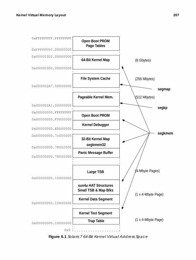
Kernel Virtual Memory Layout 207
Figure 6.1 Solaris 7 64-Bit Kernel Virtual Address Space
0xFFFFFFFF.FFFFFFFF
0x0
Open Boot PROMPage Tables
64-Bit Kernel Map
segkmem
File System Cache
segmap
Pageable Kernel Mem.
segkp
Open Boot PROM
Kernel Debugger
32-Bit Kernel Map
segkmem32
Panic Message Buffer
Large TSB
sun4u HAT StructuresSmall TSB & Map Blks
Kernel Data Segment
Kernel Text Segment
Trap Table0x00000000.10000000
0x00000000.10400000
0x00000000.10400000
0x00000000.78000000
0x00000000.78002000
0x00000000.7c000000
0x00000000.EDD00000
0x00000000.F0000000
0x00000000.FFFFFFFF
0x000002A1.00000000
0x000002A7.50000000
0x00000300.00000000
0x00000302.00000000
0xFFFFFFFC.00000000
(8 Gbytes)
(256 Mbytes)
(512 Mbytes)
(4-Mbyte Pages)
(1 x 4-Mbyte Page)
(1 x 4-Mbyte Page)

208 Kernel Memory
6.1.2 The Kernel Text and Data Segments
The kernel text and data segments are created when the kernel core is loaded andexecuted. The text segments contain the instructions, and the data segment con-tains the initialized variables from the kernel/unix image file, which is loaded atboot time by the kernel bootstrap loader.
The kernel text and data are mapped into the kernel address space by the OpenBoot PROM, prior to general startup of the kernel, to allow the base kernel code tobe loaded and executed. Shortly after the kernel loads, the kernel then creates thekernel address space and the segkmem kernel memory driver creates segments forkernel text and kernel data.
On systems that support large pages, the kernel creates a large translationmapping for the first four megabytes of the kernel text and data segments andthen locks that mapping into the MMU’s TLB. Mapping the kernel into large pagesgreatly reduces the number of TLB entries required for the kernel’s working setand has a dramatic impact on general system performance. Performance wasincreased by as much as 10 percent, for two reasons:
1.The time spent in TLB miss handlers for kernel code was reduced to almostzero.
2. The number of TLB entries used by the kernel was dramatically reduced,leaving more TLB entries for user code and reducing the amount of timespent in TLB miss handlers for user code.
On SPARC platforms, we also put the trap table at the start of the kernel text(which resides on one large page).
6.1.3 Virtual Memory Data Structures
The kernel keeps most of the virtual memory data structures required for the plat-form’s HAT implementation in a portion of the kernel data segment and a sepa-rate memory segment. The data structures and allocation location are typicallythose summarized in Table 6-1.
Table 6-1 Virtual Memory Data Structures
Platform Data Structures Locationsun4u The Translation Storage Buffer
(TSB).The HAT mapping blocks (HME),one for every page-sized virtualaddress mapping. (See “The UltraS-PARC-I and -II HAT” on page 193.)
Allocated initially from thekernel data-segment largepage, and overflows intoanother large-page, mappedsegment, just above the ker-nel data segment.
sun4m Page Tables, Page Structures Allocated in the kerneldata-segment large page.

Kernel Virtual Memory Layout 209
d with-enta-
all of“Theased to
LBecialkernel
6.1.4 The SPARC V8 and V9 Kernel Nucleus
Required on sun4u kernel implementations is a core area of memory that can be accesseout missing in the TLB. This memory area is necessary because the sun4u SPARC implemtion uses a software TLB replacement mechanism to fill the TLB, and hence we requirethe TLB miss handler data structures to be available during a TLB miss. As we discuss inUltraSPARC-I and -II HAT” on page 193, the TLB is filled from a software buffer, knownthe translation storage buffer (TSB), of the TLB entries, and all of the data structures needhandle a TLB miss and to fill the TLB from the TSB must be available with wired-down Tmappings. To accommodate this requirement, SPARC V8 and SPARC V9 implement a spcore of memory, known as the nucleus. On sun4u systems, the nucleus is the kernel text,data, and the additional “large TSB” area, all of which are allocated from large pages.
6.1.5 Loadable Kernel Module Text and Data
The kernel loadable modules require memory for their executable text and data.On sun4u, up to 256 Kbytes of module text and data are allocated from the samesegment as the kernel text and data, and after the module text and data areloaded from the general kernel allocation area, the kernel map segment. The loca-tion of kernel module text and data is shown in Table 6-2.
sun4d Page Tables, Page Structures Allocated in the kerneldata-segment large page.
x86 Page Tables, Page Structures Allocated from a separateVM data structure’s segment.
Table 6-2 Kernel Loadable Module Allocation
Platform Module Kernel and Text Allocationsun4u64 bit
Up to 256 Kbytes of kernel module are loaded from the samelarge pages as the kernel text and data. The remainder areloaded from the 32-bit kernel map segment, a segment that isspecifically for module text and data.
sun4u32 bit
Up to 256 Kbytes of kernel module are loaded from the samelarge pages as the kernel text and data. The remainder areloaded from the general kernel memory allocation segment, thekernel map segment.
sun4m Loadable module text and data are loaded from the generalkernel memory allocation segment, the kernelmap segment.
sun4d Loadable module text and data are loaded from the generalkernel memory allocation segment, the kernelmap segment.
Table 6-1 Virtual Memory Data Structures (Continued)
Platform Data Structures Location

210 Kernel Memory
We can see which modules fitted into the kernel text and data by looking at themodule load addresses with the modinfo command.
Using the modinfo command, we can see on a sun4u system that the initial mod-ules are loaded from the kernel-text large page. (Address 0x1030bc90 lies withinthe kernel-ext large page, which starts at 0x10000000.)
On 64-bit sun4u platforms, we have an additional segment for the spillover ker-nel text and data. The reason for having the segment is that the address at whichthe module text is loaded must be within a 32-bit offset from the kernel text.That’s because the 64-bit kernel is compiled with the ABS32 flag so that the ker-nel can fit all instruction addresses within a 32-bit register. The ABS32 instruc-tion mode provides a significant performance increase and allows the 64-bit kernelto provide similar performance to the 32-bit kernel. Because of that, a separatekernel map segment (segkmem32) within a 32-bit offset of the kernel text is usedfor spillover module text and data.
Solaris does allow some portions of the kernel to be allocated from pageable mem-ory. That way, data structures directly related to process context can be swappedout with the process during a process swap-out operation. Pageable memory isrestricted to those structures that are not required by the kernel when the processis swapped out:
• Lightweight process stacks• The TNF Trace buffers
x86 Up to 256 Kbytes of kernel module are loaded from the samelarge pages as the kernel text and data. The remainder areloaded from an additional segment, shared by HAT data struc-tures and module text/data.
# modinfo Id Loadaddr Size Info Rev Module Name 5 1010c000 4b63 1 1 specfs (filesystem for specfs) 7 10111654 3724 1 1 TS (time sharing sched class) 8 1011416c 5c0 - 1 TS_DPTBL (Time sharing dispatch table) 9 101141c0 29680 2 1 ufs (filesystem for ufs)
.
.
.
. 97 10309b38 28e0 52 1 shmsys (System V shared memory) 97 10309b38 28e0 52 1 shmsys (32-bit System V shared memory) 98 1030bc90 43c - 1 ipc (common ipc code) 99 78096000 3723 18 1 ffb (ffb.c 6.42 Aug 11 1998 11:20:45)100 7809c000 f5ee - 1 xfb (xfb driver 1.2 Aug 11 1998 11:2)102 780c2000 1eca - 1 bootdev (bootdev misc module)
Table 6-2 Kernel Loadable Module Allocation (Continued)
Platform Module Kernel and Text Allocation

Kernel Virtual Memory Layout 211
• Special pages, such as the page of memory that is shared between user andkernel for scheduler preemption control
Pageable memory is allocated and swapped by the seg_kp segment and is onlyswapped out to its backing store when the memory scheduler (swapper) is acti-vated. (See “The Memory Scheduler” on page 189.)
6.1.6 The Kernel Address Space and Segments
The kernel address space is represented by the address space pointed to by thesystem object, kas . The segment drivers manage the manipulation of the seg-ments within the kernel address space (see Figure 6.2).
The full list of segment drivers the kernel uses to create and manage kernel map-pings is shown in Table 6-3. The majority of the kernel segments are manually cal-culated and placed for each platform, with the base address and offset hard-codedinto a platform-specific header file. See Appendix B, “Kernel Virtual Address
a_segs
struct as
a_sizea_nsegsa_flagsa_hata_tail
s_base
struct seg
s_sizes_ass_prevs_nexts_ops
s_base
struct seg
s_sizes_ass_prevs_nexts_ops
s_base
struct seg
s_sizes_ass_prevs_nexts_ops
a_watchp
kas
Open Boot PROMPage Tables
64-Bit Kernel Map
File System Cache
Pageable Kernel Mem.
Open Boot PROM
Kernel Debugger
32-Bit Kernel Mapsegkmem32
Panic Message Buffer
Large TSB
sun4u HAT StructuresSmall TSB & Map Blks
Kernel Data Segment
Kernel Text SegmentTrap Table
Figure 6.2 Kernel Address Space

212 Kernel Memory
Maps” for a complete reference of platform-specific kernel allocation and addressmaps.
6.2 Kernel Memory Allocation
Kernel memory is allocated at different levels, depending on the desired allocationcharacteristics. At the lowest level is the page allocator, which allocates unmappedpages from the free lists so the pages can then be mapped into the kernel’s addressspace for use by the kernel.
Allocating memory in pages works well for memory allocations that requirepage-sized chunks, but there are many places where we need memory allocationssmaller than one page; for example, an in-kernel inode requires only a few hun-dred bytes per inode, and allocating one whole page (8 Kbytes) would be wasteful.For this reason, Solaris has an object-level kernel memory allocator in addition tothe page-level allocator to allocate arbitrarily sized requests, stacked on top of thepage-level allocator. The kernel also needs to manage where pages are mapped, afunction that is provided by the resource map allocator. The high-level interactionbetween the allocators is shown in Figure 6.3.
Table 6-3 Solaris 7 Kernel Memory Segment Drivers
Segment Functionseg_kmem Allocates and maps nonpageable kernel memory pages.seg_kp Allocates, maps, and handles page faults for pageable
kernel memory.seg_nf Nonfaulting kernel memory driver.seg_map Maps the file system cache into the kernel address
space.

Kernel Memory Allocation 213
Figure 6.3 Different Levels of Memory Allocation
6.2.1 The Kernel Map
We access memory in the kernel by acquiring a section of the kernel’s virtualaddress space and then mapping physical pages to that address. We can acquirethe physical pages one at a time from the page allocator by callingpage_create_va() , but to use these pages, we first need to map them. A sectionof the kernel’s address space, known as the kernel map, is set aside for gen-eral-purpose mappingsp. (See Figure 6.1 for the location of the sun4u kernelmap;see also Appendix B, “Kernel Virtual Address Maps” for kernel maps on otherplatforms.)
The kernel map is a separate kernel memory segment containing a large area ofvirtual address space that is available to kernel consumers who require virtualaddress space for their mappings. Each time a consumer uses a piece of the kernelmap, we must record some information about which parts of the kernel map are
Raw Page
Allocator
Kernel
AllocatorMemory (Slab)
segkmemProcess
Driver
seg_vn
Process
(malloc)
Memory
inodes,proc structs
stream,buffers, etc.
drivers
page-levelrequests
kmem_alloc()kmem_cache_alloc()
page_create_va() page_create_va()
processes
kernelmap
rmalloc()
segkmem_getpages()

214 Kernel Memory
free and which parts are allocated, so that we know where to satisfy new requests.To record the information, we use a general-purpose allocator to keep track of thestart and length of the mappings that are allocated from the kernel map area. Theallocator we use is the resource map allocator, which is used almost exclusively formanaging the kernel map virtual address space.
The kernel map area is large, up to 8 Gbytes on 64-bit sun4u systems, and canquickly become fragmented if it accommodates many consumers with differ-ent-sized requests. It is up to the resource map allocator to try to keep the kernelmap area as unfragmented as possible.
6.2.2 The Resource Map Allocator
Solaris uses the resource map allocator to manage the kernel map. To keep trackof the areas of free memory within the map, the resource map allocator uses a sim-ple algorithm to keep a list of start/length pairs that point to each area of freememory within the map. The map entries are sorted in ascending order to make itquicker to find entries, allowing faster allocation. The map entries are shown inthe following map structure, which can be found in the <sys/map.h> header file.
The area managed by the resource map allocator is initially described by just onemap entry representing the whole area as one contiguous free chunk. As more allo-cations are made from the area, more map entries are used to describe the area,and as a result, the map becomes ever more fragmented over time.
The resource map allocator uses a first-fit algorithm to find space in the map tosatisfy new requests, which means that it attempts to find the first available slotin the map that fits the request. The first-fit algorithm provides a fast find alloca-tion at the expense of map fragmentation after time. For this reason, it is impor-tant to ensure that kernel subsystems do not perform an excessive amount of mapallocation and freeing. The kernel slab allocator (discussed next) should be used forthese types of requests.
Map resource requests are made with the rmalloc() call, and resources arereturned to the map by rmfree() . Resource maps are created with the rmalloc-map() function and destroyed with the rmfreemap() function. The functions thatimplement the resource map allocator are shown in Table 6-4.
6.2.3 The Kernel Memory Segment Driver
The segkmem segment driver performs two major functions: it manages the cre-ation of general-purpose memory segments in the kernel address space, and it also
struct map { size_t m_size; /* size of this segment of the map */ ulong_t m_addr; /* resource-space addr of start of segment */};
Header File <vm/rm.h>

Kernel Memory Allocation 215
provides functions that implement a page-level memory allocator by using one ofthose segments—the kernel map segment.
Table 6-4 Solaris 7 Resource Map Allocator Functions from <sys/map.h>
Function Descriptionrmallocmap() Dynamically allocates a map. Does not sleep.
Driver-defined basic locks, read/write locks, andsleep locks can be held across calls to this func-tion.DDI-/DKI-conforming drivers may only use mapstructures that have been allocated and initial-ized with rmallocmap() .
rmallocmap_wait() Dynamically allocates a map. It does sleep.DDI-/DKI-conforming drivers can only use mapstructures that have been allocated and initial-ized with rmallocmap() andrmallocmap_wait() .
rmfreemap() Frees a dynamically allocated map. Does notsleep.Driver-defined basic locks, read/write locks, andsleep locks can be held across calls to this func-tion.Before freeing the map, the caller must ensurethat nothing is using space managed by the mapand that nothing is waiting for space in the map.
rmalloc() Allocates size units from the given map. Returnsthe base of the allocated space. In a map, theaddresses are increasing and the list is termi-nated by a 0 size.Algorithm is first-fit.
rmalloc_wait() Like rmalloc , but waits if necessary until spaceis available.
rmalloc_locked() Like rmalloc , but called with lock on map held.rmfree() Frees the previously allocated space at addr of
size units into the specified map.Sorts addr into map and combines on one or bothends if possible.
rmget() Allocates size units from the given map, start-ing at address addr . Returns addr if successful, 0if not. This may cause the creation or destructionof a resource map segment.This routine returns failure status if there is notenough room for a required additional map seg-ment.

216 Kernel Memory
The segkmem segment driver implements the segment driver methods describedin Section 5.4, “Memory Segments,” on page 143, to create general-purpose, non-pageable memory segments in the kernel address space. The segment driver doeslittle more than implement the segkmem_create method to simply link segmentsinto the kernel’s address space. It also implements protection manipulation meth-ods, which load the correct protection modes via the HAT layer for segkmem seg-ments. The set of methods implemented by the segkmem driver is shown in Table6-5.
The second function of the segkmem driver is to implement a page-level memoryallocator by combined use of the resource map allocator and page allocator. Thepage-level memory allocator within the segkmem driver is implemented with thefunction kmem_getpages() . The kmem_getpages() function is the kernel’s cen-tral allocator for wired-down, page-sized memory requests. Its main client is thesecond-level memory allocator, the slab allocator, which uses large memory areasallocated from the page-level allocator to allocate arbitrarily sized memory objects.We’ll cover more on the slab allocator further in this chapter.
The kmem_getpages() function allocates page-sized chunks of virtual addressspace from the kernelmap segment. The kernelmap segment is only one of manysegments created by the segkmem driver, but it is the only one from which the seg-kmem driver allocates memory.
The resource map allocator allocates portions of virtual address space withinthe kernelmap segment but on its own does not allocate any physical memoryresources. It is used together with the page allocator, page_create_va() , and thehat_memload() functions to allocate physical mapped memory. The resource mapallocator allocates some virtual address space, the page allocator allocates pages,and the hat_memload() function maps those pages into the virtual address spaceprovided by the resource map. A client of the segkmem memory allocator canacquire pages with kmem_getpages and then return them to the map withkmem_freepages , as shown in Table 6-6.
Pages allocated through kmem_getpages are not pageable and are one of the fewexceptions in the Solaris environment where a mapped page has no logically asso-ciated vnode . To accommodate that case, a special vnode , kvp , is used. All pagescreated through the segkmem segment have kvp as the vnode in their identity—this allows the kernel to identify wired-down kernel pages.
Table 6-5 Solaris 7 segkmem Segment Driver Methods
Function Descriptionsegkmem_create() Creates a new kernel memory segment.segkmem_setprot() Sets the protection mode for the supplied segment.segkmem_checkprot() Checks the protection mode for the supplied segment.segkmem_getprot() Gets the protection mode for the current segment.

Kernel Memory Allocation 217
6.2.4 The Kernel Memory Slab Allocator
In this section, we introduce the general-purpose memory allocator, known as theslab allocator. We begin with a quick walk-through of the slab allocator features,then look at how the allocator implements object caching, and follow up with amore detailed discussion on the internal implementation.
6.2.4.1 Slab Allocator Overview
Solaris provides a general-purpose memory allocator that provides arbitrarilysized memory allocations. We refer to this allocator as the slab allocator because itconsumes large slabs of memory and then allocates smaller requests with portionsof each slab. We use the slab allocator for memory requests that are:
• Smaller than a page size• Not an even multiple of a page size• Frequently going to be allocated and freed, so would otherwise fragment the
kernel map
The slab allocator was introduced in Solaris 2.4, replacing the buddy allocator thatwas part of the original SVR4 Unix. The reasons for introducing the slab allocatorwere as follows:
• The SVR4 allocator was slow to satisfy allocation requests.• Significant fragmentation problems arose with use of the SVR4 allocator.• The allocator footprint was large, wasting a lot of memory.
• With no clean interfaces for memory allocation, code was duplicated in manyplaces.
The slab allocator solves those problems and dramatically reduces overall systemcomplexity. In fact, when the slab allocator was integrated into Solaris, it resultedin a net reduction of 3,000 lines of code because we could centralize a great deal ofthe memory allocation code and could remove a lot of the duplicated memory allo-cator functions from the clients of the memory allocator.
Table 6-6 Solaris 7 Kernel Page Level Memory Allocator
Function Descriptionkmem_getpages() Allocates npages pages worth of system virtual
address space, and allocates wired-down pageframes to back them.
If flag is KM_NOSLEEP, blocks until addressspace and page frames are available.
kmem_freepages() Frees npages (MMU) pages allocated withkmem_getpages() .

218 Kernel Memory
The slab allocator is significantly faster than the SVR4 allocator it replaced.Table 6-7 shows some of the performance measurements that were made when theslab allocator was first introduced.
The slab allocator provides substantial additional functionality, including the fol-lowing:
• General-purpose, variable-sized memory object allocation
• A central interface for memory allocation, which simplifies clients of the allo-cator and reduces duplicated allocation code
• Very fast allocation/deallocation of objects
• Low fragmentation / small allocator footprint• Full debugging and auditing capability• Coloring to optimize use of CPU caches• Per-processor caching of memory objects to reduce contention• A configurable back-end memory allocator to allocate objects other than regu-
lar wired-down memory
The slab allocator uses the term object to describe a single memory allocation unit,cache to refer to a pool of like objects, and slab to refer to a group of objects thatreside within the cache. Each object type has one cache, which is constructed fromone or more slabs. Figure 6.4 shows the relationship between objects, slabs, andthe cache. The example shows 3-Kbyte memory objects within a cache, backed by8-Kbyte pages.
Table 6-7 Performance Comparison of the Slab Allocator
Operation SVR4 SlabAverage time to allocate and free 9.4 µs 3.8 µsTotal fragmentation (wasted memory) 46% 14%Kenbus benchmark performance(number of scripts executed per second)
199 233

Kernel Memory Allocation 219
Figure 6.4 Objects, Caches, Slabs, and Pages of Memory
The slab allocator solves many of the fragmentation issues by grouping differ-ent-sized memory objects into separate caches, where each object cache has its ownobject size and characteristics. Grouping the memory objects into caches of similarsize allows the allocator to minimize the amount of free space within each cache byneatly packing objects into slabs, where each slab in the cache represents a contig-uous group of pages. Since we have one cache per object type, we would expect tosee many caches active at once in the Solaris kernel. For example, we shouldexpect to see one cache with 440 byte objects for UFS inodes, another cache of 56byte objects for file structures, another cache of 872 bytes for LWP structures, andseveral other caches.
The allocator has a logical front end and back end. Objects are allocated fromthe front end, and slabs are allocated from pages supplied by the back-end pageallocator. This approach allows the slab allocator to be used for more than regularwired-down memory; in fact, the allocator can allocate almost any type of memoryobject. The allocator is, however, primarily used to allocate memory objects fromphysical pages by using kmem_getpages as the back-end allocator.
Caches are created with kmem_cache_create() , once for each type of memoryobject. Caches are generally created during subsystem initialization, for example,in the init routine of a loadable driver. Similarly, caches are destroyed with thekmem_cache_destroy() function. Caches are named by a string provided as anargument, to allow friendlier statistics and tags for debugging. Once a cache is cre-ated, objects can be created within the cache with kmem_cache_alloc() , which
Cache (for 3-Kbyte objects)
Objects (3-Kbyte)
Slabs
Contiguous8-Kbyte Pagesof Memory
Back
-end
Allo
cato
r: km
em_g
etpa
ges(
)
Mem
ory
Req
uest
sC
lient

220 Kernel Memory
creates one object of the size associated with the cache from which the object is cre-ated. Objects are returned to the cache with kmem_cache_free() .
6.2.4.2 Object Caching
The slab allocator makes use of the fact that most of the time objects are heavilyallocated and deallocated, and many of the slab allocator’s benefits arise fromresolving the issues surrounding allocation and deallocation. The allocator tries todefer most of the real work associated with allocation and deallocation until it isreally necessary, by keeping the objects alive until memory needs to be returned tothe back end. It does this by telling the allocator what the object is being used for,so that the allocator remains in control of the object’s true state.
So, what do we really mean by keeping the object alive? If we look at what asubsystem uses memory objects for, we find that a memory object typically con-sists of two common components: the header or description of what resides withinthe object and associated locks; and the actual payload that resides within theobject. A subsystem typically allocates memory for the object, constructs the objectin some way (writes a header inside the object or adds it to a list), and then cre-ates any locks required to synchronize access to the object. The subsystem thenuses the object. When finished with the object, the subsystem must deconstruct theobject, release locks, and then return the memory to the allocator. In short, a sub-system typically allocates, constructs, uses, deallocates, and then frees the object.
If the object is being created and destroyed often, then a great deal of work isexpended constructing and deconstructing the object. The slab allocator does awaywith this extra work by caching the object in its constructed form. When the clientasks for a new object, the allocator simply creates or finds an available con-structed object. When the client returns an object, the allocator does nothing otherthan mark the object as free, leaving all of the constructed data (header informa-tion and locks) intact. The object can be reused by the client subsystem withoutthe allocator needing to construct or deconstruct—the construction and decon-struction is only done when the cache needs to grow or shrink. Deconstruction isdeferred until the allocator needs to free memory back to the back-end allocator.
To allow the slab allocator to take ownership of constructing and deconstruct-ing objects, the client subsystem must provide a constructor and destructormethod. This service allows the allocator to construct new objects as required andthen to deconstruct objects later, asynchronously to the client’s memory requests.The kmem_cache_create() interface supports this feature by providing a con-structor and destructor function as part of the create request.
The slab allocator also allows slab caches to be created with no constructor ordestructor, to allow simple allocation and deallocation of simple raw memoryobjects.
The slab allocator moves a lot of the complexity out of the clients and central-izes memory allocation and deallocation policies. At some points, the allocator mayneed to shrink a cache as a result of being notified of a memory shortage by the

Kernel Memory Allocation 221
VM system. At this time, the allocator can free all unused objects by calling thedestructor for each object that is marked free and then returning unused slabs tothe back-end allocator. A further callback interface is provided in each cache sothat the allocator can let the client subsystem know about the memory pressure.This callback is optionally supplied when the cache is created and is simply a func-tion that the client implements to return, by means of kmem_cache_free() , asmany objects to the cache as possible.
A good example is a file system, which uses objects to store the inodes. The slaballocator manages inode objects; the cache management, construction, and decon-struction of inodes are handed over to the slab allocator. The file system simplyasks the slab allocator for a “new inode” each time it requires one. For example, afile system could call the slab allocator to create a slab cache, as shown below.
The example shows that we create a cache named inode_cache , with objects ofthe size of an inode, no alignment enforcement, a constructor and a destructorfunction, and a reclaim function. The back-end memory allocator is specified asNULL, which by default allocates physical pages from the segkmem page allocator.
We can see from the statistics exported by the slab allocator that the UFS filesystem uses a similar mechanism to allocate its inodes. We use the netstat -kfunction to dump the statistics. (We discuss allocator statistics in more detail in“Slab Allocator Statistics” on page 229.)
inode_cache = kmem_cache_create("inode_cache",sizeof (struct inode), 0, inode_cache_constructor,inode_cache_destructor, inode_cache_reclaim,NULL, NULL, 0);
struct inode *inode = kmem_cache_alloc(inode_cache, 0);
# netstat -k ufs_inode_cacheufs_inode_cache:buf_size 440 align 8 chunk_size 440 slab_size 8192 alloc 20248589alloc_fail 0 free 20770500 depot_alloc 657344 depot_free 678433depot_contention 85 global_alloc 602986 global_free 578089buf_constructed 0 buf_avail 7971 buf_inuse 24897 buf_total 32868buf_max 41076 slab_create 2802 slab_destroy 976 memory_class 0hash_size 0 hash_lookup_depth 0 hash_rescale 0 full_magazines 0empty_magazines 0 magazine_size 31 alloc_from_cpu0 9583811free_to_cpu0 10344474 buf_avail_cpu0 0 alloc_from_cpu1 9404448free_to_cpu1 9169504 buf_avail_cpu1 0

222 Kernel Memory
The allocator interfaces are shown in Table 6-8.
Caches are created with the kmem_cache_create() function, which can option-ally supply callbacks for construction, deletion, and cache reclaim notifications.The callback functions are described in Table 6-9.
Table 6-8 Solaris 7 Slab Allocator Interfaces from <sys/kmem.h >
Function Descriptionkmem_cache_create() Creates a new slab cache with the supplied
name, aligning objects on the boundary suppliedwith alignment.The constructor, destructor, and reclaim func-tions are optional and can be supplied as NULL.An argument can be provided to the constructorwith arg .The back-end memory allocator can also be spec-ified or supplied as NULL. If a NULL back-endallocator is supplied, then the default allocator,kmem_getpages() , is used.Flags can supplied as be KMC_NOTOUCH,KMC_NODEBUG, KMC_NOMAGAZINE, andKMC_NOHASH.
kmem_cache_destroy() Destroys the cache referenced by cp .kmem_cache_alloc() Allocates one object from the cache referenced
by cp . Flags can be supplied as either KM_SLEEPor KM_NOSLEEP.
kmem_cache_free() Returns the buffer buf to the cache referencedby cp .
kmem_cache_stat() Returns a named statistic about a particularcache that matches the string name. Finds aname by looking at the kstat slab cache nameswith netstat -k .
Table 6-9 Slab Allocator Callback Interfaces from <sys/kmem.h >
Function Descriptionconstructor() Initializes the object buf . The arguments arg and
flag are those provided duringkmem_cache_create() .
destructor() Destroys the object buf . The argument arg isthat provided during kmem_cache_create() .
reclaim() Where possible, returns objects to the cache. Theargument is that provided duringkmem_cache_create() .

Kernel Memory Allocation 223
6.2.4.3 General-Purpose Allocations
In addition to object-based memory allocation, the slab allocator provides back-ward-compatible, general-purpose memory allocation routines. These routines allo-cate arbitrary-length memory by providing a method to malloc() . The slaballocator maintains a list of various-sized slabs to accommodate kmem_alloc()requests and simply converts the kmem_alloc() request into a request for anobject from the nearest-sized cache. The sizes of the caches used forkmem_alloc() are named kmem_alloc_ n, where n is the size of the objectswithin the cache (see Section 6.2.4.9, “Slab Allocator Statistics,” on page 229). Thefunctions are shown in Table 6-10.
6.2.4.4 Slab Allocator Implementation
The slab allocator implements the allocation and management of objects to thefront-end clients, using memory provided by the back-end allocator. In our intro-duction to the slab allocator, we discussed in some detail the virtual allocationunits: the object and the slab. The slab allocator implements several internal lay-ers to provide efficient allocation of objects from slabs. The extra internal layersreduce the amount of contention between allocation requests from multiplethreads, which ultimately allows the allocator to provide good scalability on largeSMP systems.
Figure 6.5 shows the internal layers of the slab allocator. The additional layersprovide a cache of allocated objects for each CPU, so a thread can allocate an objectfrom a local per-CPU object cache without having to hold a lock on the global slabcache. For example, if two threads both want to allocate an inode object from theinode cache, then the first thread’s allocation request would hold a lock on theinode cache and would block the second thread until the first thread has its objectallocated. The per-cpu cache layers overcome this blocking with an object cache perCPU to try to avoid the contention between two concurrent requests. Each CPUhas its own short-term cache of objects, which reduces the amount of time thateach request needs to go down into the global slab cache.
Table 6-10 General-Purpose Memory Allocation
Function Descriptionkmem_alloc() Allocates size bytes of memory. Flags can be
either KM_SLEEP or KM_NOSLEEP.kmem_zalloc() Allocates size bytes of zeroed memory. Flags can
be either KM_SLEEP or KM_NOSLEEP.kmem_free() Returns to the allocator the buffer pointed to by
buf and size .

224 Kernel Memory
Color Buffer Tag Buffer Tag Buffer Tag
bufctl bufctl bufctl
Slab
FullMagazines
EmptyMagazines
FullEmpty FullEmptyCPU 0Cache
CPU 1Cache
Global (Slab) Layer
Depot Layer
CPU Layer
kmem_cache_alloc() / kmem_cache_free()
Back-end Page Allocator
Figure 6.5 Slab Allocator Internal Implementation

Kernel Memory Allocation 225
The layers shown in Figure 6.5 are separated into the slab layer, the depot layer,and the CPU layer. The upper two layers (which together are known as the maga-zine layer) are caches of allocated groups of objects and use a military analogy ofallocating rifle rounds from magazines. Each per-CPU cache has magazines of allo-cated objects and can allocate objects (rounds) from its own magazines withouthaving to bother the lower layers. The CPU layer needs to allocate objects from thelower (depot) layer only when its magazines are empty. The depot layer refills mag-azines from the slab layer by assembling objects, which may reside in many differ-ent slabs, into full magazines.
6.2.4.5 The CPU Layer
The CPU layer caches groups of objects to minimize the number of times that anallocation will need to go down to the lower layers. This means that we can satisfythe majority of allocation requests without having to hold any global locks, thusdramatically improving the scalability of the allocator.
Continuing the military analogy: three magazines of objects are kept in theCPU layer to satisfy allocation and deallocation requests—a full, a half-allocated,and an empty magazine are on hand. Objects are allocated from the half-emptymagazine, and until the magazine is empty, all allocations are simply satisfiedfrom the magazine. When the magazine empties, an empty magazine is returnedto the magazine layer, and objects are allocated from the full magazine that wasalready available at the CPU layer. The CPU layer keeps the empty and full maga-zine on hand to prevent the magazine layer from having to construct and decon-struct magazines when on a full or empty magazine boundary. If a client rapidlyallocates and deallocates objects when the magazine is on a boundary, then theCPU layer can simply use its full and empty magazines to service the requests,rather than having the magazine layer deconstruct and reconstruct new maga-zines at each request. The magazine model allows the allocator to guarantee thatit can satisfy at least a magazine size of rounds without having to go to the depotlayer.
6.2.4.6 The Depot Layer
The depot layer assembles groups of objects into magazines. Unlike a slab, a maga-zine’s objects are not necessarily allocated from contiguous memory; rather, a mag-azine contains a series of pointers to objects within slabs.
The number of rounds per magazine for each cache changes dynamically,depending on the amount of contention that occurs at the depot layer. The morerounds per magazine, the lower the depot contention, but more memory is con-sumed. Each range of object sizes has an upper and lower magazine size. Table6-11 shows the magazine size range for each object size.

226 Kernel Memory
A slab allocator maintenance thread is scheduled every 15 seconds (controlled bythe tunable kmem_update_interval ) to recalculate the magazine sizes. If signifi-cant contention has occurred at the depot level, then the magazine size is bumpedup. Refer to Table 6-12 on page 227 for the parameters that control magazineresizing.
6.2.4.7 The Global (Slab) Layer
The global slab layer allocates slabs of objects from contiguous pages of physicalmemory and hands them up to the magazine layer for allocation. The global slablayer is used only when the upper layers need to allocate or deallocate entire slabsof objects to refill their magazines.
The slab is the primary unit of allocation in the slab layer. When the allocatorneeds to grow a cache, it acquires an entire slab of objects. When the allocatorwants to shrink a cache, it returns unused memory to the back end by deallocat-ing a complete slab. A slab consists of one or more pages of virtually contiguousmemory carved up into equal-sized chunks, with a reference count indicating howmany of those chunks have been allocated.
The contents of each slab are managed by a kmem_slab data structure thatmaintains the slab’s linkage in the cache, its reference count, and its list of freebuffers. In turn, each buffer in the slab is managed by a kmem_bufctl structurethat holds the freelist linkage, the buffer address, and a back-pointer to the con-trolling slab.
For objects smaller than 1/8th of a page, the slab allocator builds a slab by allo-cating a page, placing the slab data at the end, and dividing the rest intoequal-sized buffers. Each buffer serves as its own kmem_bufctl while on thefreelist. Only the linkage is actually needed, since everything else is computable.These are essential optimizations for small buffers; otherwise, we would end upallocating almost as much memory for kmem_bufctl as for the buffers them-selves. The free-list linkage resides at the end of the buffer, rather than the begin-ning, to facilitate debugging. This location is driven by the empirical observation
Table 6-11 Magazine Sizes
Object SizeRange
MinimumMagazine Size
MaximumMagazine Size
0–63 15 14364–127 7 95128–255 3 47256–511 1 31512–1023 1 151024–2047 1 72048–16383 1 316384– 1 1
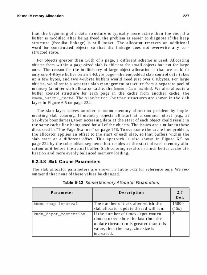
Kernel Memory Allocation 227
that the beginning of a data structure is typically more active than the end. If abuffer is modified after being freed, the problem is easier to diagnose if the heapstructure (free-list linkage) is still intact. The allocator reserves an additionalword for constructed objects so that the linkage does not overwrite any con-structed state.
For objects greater than 1/8th of a page, a different scheme is used. Allocatingobjects from within a page-sized slab is efficient for small objects but not for largeones. The reason for the inefficiency of large-object allocation is that we could fitonly one 4-Kbyte buffer on an 8-Kbyte page—the embedded slab control data takesup a few bytes, and two 4-Kbyte buffers would need just over 8 Kbytes. For largeobjects, we allocate a separate slab management structure from a separate pool ofmemory (another slab allocator cache, the kmem_slab_cache ). We also allocate abuffer control structure for each page in the cache from another cache, thekmem_bufctl_cache . The slab /bufctl /buffer structures are shown in the slablayer in Figure 6.5 on page 224.
The slab layer solves another common memory allocation problem by imple-menting slab coloring. If memory objects all start at a common offset (e.g., at512-byte boundaries), then accessing data at the start of each object could result inthe same cache line being used for all of the objects. The issues are similar to thosediscussed in “The Page Scanner” on page 178. To overcome the cache line problem,the allocator applies an offset to the start of each slab, so that buffers within theslab start at a different offset. This approach is also shown in Figure 6.5 onpage 224 by the color offset segment that resides at the start of each memory allo-cation unit before the actual buffer. Slab coloring results in much better cache uti-lization and more evenly balanced memory loading.
6.2.4.8 Slab Cache Parameters
The slab allocator parameters are shown in Table 6-12 for reference only. We rec-ommend that none of these values be changed.
Table 6-12 Kernel Memory Allocator Parameters
Parameter Description 2.7Def.
kmem_reap_interval The number of ticks after which theslab allocator update thread will run.
15000(15s)
kmem_depot_contention If the number of times depot conten-tion occurred since the last time theupdate thread ran is greater than thisvalue, then the magazine size isincreased.
3

228 Kernel Memory
kmem_reapahead If the amount of free memory fallsbelow cachefree +kmem_reapahead , then the slab alloca-tor will give back as many slabs as pos-sible to the back-end page allocator.
0
Table 6-12 Kernel Memory Allocator Parameters (Continued)
Parameter Description 2.7Def.

Kernel Memory Allocation 229
6.2.4.9 Slab Allocator Statistics
Two forms of slab allocator statistics are available: global statistics and per-cachestatistics. The global statistics are available through the crash utility and displaya summary of the entire cache list managed by the allocator.
# crashdumpfile = /dev/mem, namelist = /dev/ksyms, outfile = stdout> kmastat buf buf buf memory #allocationscache name size avail total in use succeed fail---------- ----- ----- ----- -------- ------- ----kmem_magazine_1 16 483 508 8192 6664 0kmem_magazine_3 32 1123 1270 40960 55225 0kmem_magazine_7 64 584 762 49152 62794 0kmem_magazine_15 128 709 945 122880 194764 0kmem_magazine_31 256 58 62 16384 24915 0kmem_magazine_47 384 0 0 0 0 0kmem_magazine_63 512 0 0 0 0 0kmem_magazine_95 768 0 0 0 0 0kmem_magazine_143 1152 0 0 0 0 0kmem_slab_cache 56 308 2159 139264 22146 0kmem_bufctl_cache 32 2129 6096 196608 54870 0kmem_bufctl_audit_cache 184 24 16464 3211264 16440 0kmem_pagectl_cache 32 102 254 8192 406134 0kmem_alloc_8 8 9888 31527 253952 115432346 0kmem_alloc_16 16 7642 18288 294912 374733170 0kmem_alloc_24 24 4432 11187 270336 30957233 0
.
.kmem_alloc_12288 12288 2 4 49152 660 0kmem_alloc_16384 16384 0 42 688128 1845 0
.
.streams_mblk 64 3988 5969 385024 31405446 0streams_dblk_32 128 795 1134 147456 72553829 0streams_dblk_64 160 716 1650 270336 196660790 0
.
.streams_dblk_8096 8192 17 17 139264 356266482 0streams_dblk_12192 12288 8 8 98304 14848223 0streams_dblk_esb 96 0 0 0 406326 0stream_head_cache 328 68 648 221184 492256 0queue_cache 456 109 1513 729088 1237000 0syncq_cache 120 48 67 8192 373 0qband_cache 64 125 635 40960 1303 0linkinfo_cache 48 156 169 8192 90 0strevent_cache 48 153 169 8192 5442622 0as_cache 120 45 201 24576 158778 0seg_skiplist_cache 32 540 1524 49152 1151455 0anon_cache 48 1055 71825 3481600 7926946 0anonmap_cache 48 551 4563 221184 5805027 0segvn_cache 88 686 6992 622592 9969087 0flk_edges 48 0 0 0 1 0physio_buf_cache 224 0 0 0 98535107 0snode_cache 240 39 594 147456 1457746 0ufs_inode_cache 440 8304 32868 14958592 20249920 0
.
.---------- ----- ----- ----- -------- ------- ----permanent - - - 98304 501 0oversize - - - 9904128 406024 0---------- ----- ----- ----- -------- ------- ----Total - - - 58753024 2753193059 0

230 Kernel Memory
The kmastat command shows summary information for each statistic and a sys-temwide summary at the end. The columns are shown in Table 6-13.
A more detailed version of the per-cache statistics is exported by the kstat mecha-nism. You can use the netstat -k command to display the cache statistics, whichare described in Table 6-14.
Table 6-13 kmastat Columns
Parameter DescriptionCache name The name of the cache, as supplied during
kmem_cache_create() .buf_size The size of each object within the cache in
bytes.buf_avail The number of free objects in the cache.buf_total The total number of objects in the cache.Memory in use The amount of physical memory consumed by
the cache in bytes.Allocations succeeded The number of allocations that succeeded.Allocations failed The number of allocations that failed. These
are likely to be allocations that specifiedKM_NOSLEEP during memory pressure.
# netstat -k ufs_inode_cacheufs_inode_cache:buf_size 440 align 8 chunk_size 440 slab_size 8192 alloc 20248589alloc_fail 0 free 20770500 depot_alloc 657344 depot_free 678433depot_contention 85 global_alloc 602986 global_free 578089buf_constructed 0 buf_avail 7971 buf_inuse 24897 buf_total 32868buf_max 41076 slab_create 2802 slab_destroy 976 memory_class 0hash_size 0 hash_lookup_depth 0 hash_rescale 0 full_magazines 0empty_magazines 0 magazine_size 31 alloc_from_cpu0 9583811free_to_cpu0 10344474 buf_avail_cpu0 0 alloc_from_cpu1 9404448free_to_cpu1 9169504 buf_avail_cpu1 0
Table 6-14 Slab Allocator Per-Cache Statistics
Parameter Descriptionbuf_size The size of each object within the cache in
bytes.align The alignment boundary for objects within the
cache.chunk_size The allocation unit for the cache in bytes.

Kernel Memory Allocation 231
6.2.4.10 Slab Allocator Tracing
The slab allocator includes a general-purpose allocation tracing facility that tracksthe allocation history of objects. The facility is switched off by default and can beenabled by setting of the system variable kmem_flags . The tracing facility cap-
slab_size The size of each slab within the cache in bytes.alloc The number of object allocations that suc-
ceeded.alloc_fail The number of object allocations that failed.
(Should be zero!).free The number of objects that were freed.depot_alloc The number of times a magazine was allo-
cated in the depot layer.depot_free The number of times a magazine was freed to
the depot layer.depot_contention The number of times a depot layer allocation
was blocked because another thread was inthe depot layer.
global_alloc The number of times an allocation was madeat the global layer.
global_free The number of times an allocation was freedat the global layer.
buf_constructed Zero or the same as buf_avail .buf_avail The number of free objects in the cache.buf_inuse The number of objects used by the client.buf_total The total number of objects in the cache.buf_max The maximum number of objects the cache
has reached.slab_create The number of slabs created.slab_destroy The number of slabs destroyed.memory_class The ID of the back-end memory allocator.hash_size Buffer hash lookup statistics.hash_lookup_depth Buffer hash lookup statistics.hash_rescale Buffer hash lookup statistics.full_magazines The number of full magazines.empty_magazines The number of empty magazines.magazine_size The size of the magazine.alloc_from_cp uN Object allocations from CPU N.free_to_cpu N Objects freed to CPU N.buf_avail_cpu N Objects available to CPU N.
Table 6-14 Slab Allocator Per-Cache Statistics (Continued)
Parameter Description

232 Kernel Memory
tures the stack and history of allocations into a slab cache, named as the name ofthe cache being traced, with .DEBUGappended to it. Audit tracing can be enabledby the following:
• Setting kmem_flags to indicate the type of tracing desired, usually 0x1F toindicate all tracing
• Booting the system with kadb -d and setting kmem_flags before startup
The following simple example shows how to trace a cache that is created on alarge system, after the flags have been set. To enable tracing on all caches, the sys-tem must be booted with kadb and the kmem_flags variable set. The steps forsuch booting are shown below.
Note that the total number of allocations traced will be limited by the size of theaudit cache parameters, shown in Table 6-12 on page 227. Table 6-15 shows theparameters that control kernel memory debugging.
ok boot kadb -dResetting ...
Sun Ultra 1 UPA/SBus (UltraSPARC 167MHz), No KeyboardOpenBoot 3.1, 128 MB memory installed, Serial #8788108.Ethernet address 8:0:20:86:18:8c, Host ID: 8086188c.
Rebooting with command: boot kadb -dBoot device: /sbus/SUNW,fas@e,8800000/sd@0,0 File and args: kadb -dkadb: <return>kadb[0]: kmem_flags/Dkmem_flags:kmem_flags: 0kadb[0]: kmem_flags/W 0x1fkmem_flags: 0x0 = 0x1fkadb[0]: :c
SunOS Release 5.7 Version Generic 64-bitCopyright 1983-2000 Sun Microsystems, Inc. All rights reserved.\
Table 6-15 Kernel Memory Debugging Parameters
Parameter Description 2.7Def.
kmem_flags Set this to select the mode of kernelmemory debugging. Set to 0x1F toenable all debugging, or set the logicalAND of the following:0x1 Transaction auditing0x2 deadbeef checking0x4 red-zone checking0x8 freed buffer content logging
0

Kernel Memory Allocation 233
kmem_log_size Maximum amount of memory to use forslab allocator audit tracing.
2% ofmem.
kmem_content_maxsave The maximum number of bytes to login each entry.
256
Table 6-15 Kernel Memory Debugging Parameters (Continued)
Parameter Description 2.7Def.

234 Kernel Memory

7
MEMORYMONITORING
In the preceding chapters we covered design and implementation of the Solarisvirtual memory system. This chapter is more practical in nature and covers thetools available to monitor the VM system.
7.1 A Quick Introduction to Memory Monitoring
In Chapter 5, “Solaris Memory Architecture” we saw that Solaris memory is usedfor several major functions, including the kernel, processes, and the file systemcache. The first step to understanding Solaris memory utilization is to summarize,at the global level, the following categories:
• Total physical memory available• Memory allocated internally within the Solaris kernel• Memory used for the file system page cache• Memory used by processes• Memory free
Several different Solaris utilities are required for derivation of the global sum-mary, and we will see how we can use these tools to build our summary. We laterdiscuss MemTool, a downloadable toolset you can load into the Solaris kernel toprovide even more detailed information.
235

236 Memory Monitoring
7.1.1 Total Physical Memory
From the output of the Solaris prtconf command, we can ascertain the amount oftotal physical memory.
7.1.2 Kernel Memory
We find the amount of kernel memory by using the Solaris sar command and sum-ming the three pool columns. The output is in bytes; in this example, the kernel isusing 55, 361, 536 bytes of memory.
7.1.3 Free Memory
Free memory is almost always zero because the buffer cache grows to consume freememory. Use the vmstat command to measure free memory. The first line of out-put from vmstat is an average since boot, so the real free memory figure is avail-able on the second line. The output is in kilobytes. Note that in this has changed inSolaris 8 - free memory now contains the majority of the file system cache.
7.1.4 File System Caching Memory
The file system cache uses available free memory to cache files on the file system.On most systems, the amount of free memory is almost zero because the file sys-tem cache is occupying all of the memory not being used by processes. We typicallysee free memory (reported in vmstat ) start high when a system is booted, thenslowly drop to almost zero after time. Free memory typically stays at or almost atzero until either a file system is unmounted or the system is rebooted. This behav-
# prtconf
System Configuration: Sun Microsystems sun4uMemory size: 384 MegabytesSystem Peripherals (Software Nodes):
# sar -k 1 1
SunOS devhome 5.7 SunOS_Development sun4u 02/07/00
18:12:28 sml_mem alloc fail lg_mem alloc fail ovsz_alloc fail18:12:31 8732672 7658792 0 37380096 30195320 0 9248768 0
# vmstat 3 procs memory page disk faults cpu r b w swap free re mf pi po fr de sr f0 s6 sd sd in sy cs us sy id 1 0 0 29008 38456 1 4 17 0 6 0 0 0 0 0 0 209 1755 399 5 1 94 0 0 0 514952 12720 0 8 0 0 0 0 0 0 0 0 0 232 482 330 1 0 98 0 0 0 514952 12720 0 0 0 0 0 0 0 0 0 0 0 214 432 307 0 0 100 1 0 0 514952 12720 0 0 0 0 0 0 0 0 0 0 0 192 409 271 0 0 100

A Quick Introduction to Memory Monitoring 237
ior is completely normal. In Solaris 8, the file system cache is included in freememory, so the free memory value is interpreted differently.
To look at the amount of file buffer cache, use the MemTool package. We can usethe MemTool mempscommand to dump the contents of the buffer cache, and wecan get a summary of the buffer cache memory with the MemTool prtmem com-mand.
7.1.5 Memory Shortage Detection
A critical component of performance analysis is ascertaining where the bottle-necks are. Detecting memory bottlenecks is not quite as straightforward as mea-suring processor and disk bottlenecks and requires a few more steps to arrive at aconclusion. To determine if there is a memory shortage, we need to determine thefollowing:
• Whether the applications are paging excessively because of a memory short-age
• Whether the system could benefit by making more memory available for filebuffering
The paging activity reported by the Solaris vmstat command includes both filesystem activity and application paging and is not a fail-safe method of identifyingmemory shortages. We can, however, use vmstat to rule out any question of amemory shortage in some circumstances. We recommend the following steps:
• Use vmstat to see if the system is paging. If it is not, then there is no chanceof a memory shortage. Excessive paging activity is evident by activity in thescan-rate (sr) and page-out (po) columns, where values are constantly non-zero. However, if the system is paging heavily, this is not necessarily a sign ofa memory shortage.
• Look at the activity reported for the swap device. If application paging isoccurring, then the swap device will have I/Os queued to it. Any significantI/O to the swap device is a sure sign of memory shortage.
• Use the MemTool to measure the distribution of memory in the system. If anapplication memory shortage exists, then the file system buffer cache size willbe very small (i.e., less than 10 percent of the total memory available).
# prtmem
Total memory: 241 MegabytesKernel Memory: 39 MegabytesApplication: 106 MegabytesExecutable & libs: 36 MegabytesFile Cache: 59 MegabytesFree, file cache: 3 MegabytesFree, free: 0 Megabytes
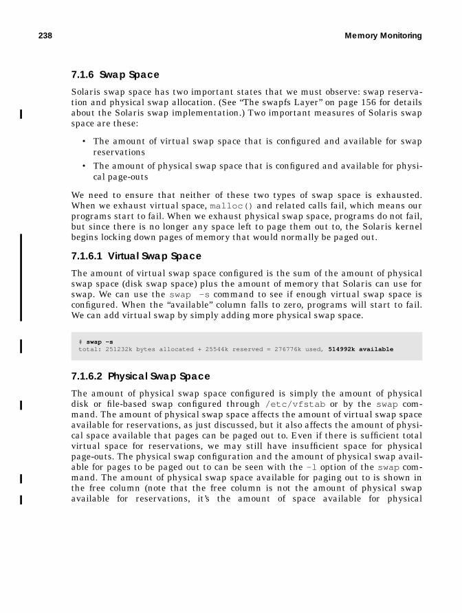
238 Memory Monitoring
7.1.6 Swap Space
Solaris swap space has two important states that we must observe: swap reserva-tion and physical swap allocation. (See “The swapfs Layer” on page 156 for detailsabout the Solaris swap implementation.) Two important measures of Solaris swapspace are these:
• The amount of virtual swap space that is configured and available for swapreservations
• The amount of physical swap space that is configured and available for physi-cal page-outs
We need to ensure that neither of these two types of swap space is exhausted.When we exhaust virtual space, malloc() and related calls fail, which means ourprograms start to fail. When we exhaust physical swap space, programs do not fail,but since there is no longer any space left to page them out to, the Solaris kernelbegins locking down pages of memory that would normally be paged out.
7.1.6.1 Virtual Swap Space
The amount of virtual swap space configured is the sum of the amount of physicalswap space (disk swap space) plus the amount of memory that Solaris can use forswap. We can use the swap -s command to see if enough virtual swap space isconfigured. When the “available” column falls to zero, programs will start to fail.We can add virtual swap by simply adding more physical swap space.
7.1.6.2 Physical Swap Space
The amount of physical swap space configured is simply the amount of physicaldisk or file-based swap configured through /etc/vfstab or by the swap com-mand. The amount of physical swap space affects the amount of virtual swap spaceavailable for reservations, as just discussed, but it also affects the amount of physi-cal space available that pages can be paged out to. Even if there is sufficient totalvirtual space for reservations, we may still have insufficient space for physicalpage-outs. The physical swap configuration and the amount of physical swap avail-able for pages to be paged out to can be seen with the -l option of the swap com-mand. The amount of physical swap space available for paging out to is shown inthe free column (note that the free column is not the amount of physical swapavailable for reservations, it’s the amount of space available for physical
# swap -stotal: 251232k bytes allocated + 25544k reserved = 276776k used, 514992k available

Memory Monitoring Tools 239
page-outs). If free physical swap is zero, then pages will no longer be paged out toswap and memory will effectively start being locked down.
Ensure that both swap -s “available” and swap -l “free” are nonzero.
7.2 Memory Monitoring Tools
To understand the memory behavior and requirements of a particular system, weneed to be able to measure the activity and operation of the virtual memory sys-tem. In this section, we look at the current tools bundled with the Solaris kernel,and we discuss some other unbundled tools that allow us to look a little deeperinto the virtual memory system.
We have two basic objectives in looking at Solaris memory: to find out where allof the memory is allocated and to look at memory (or paging) activity. Table 7-1lists the tools we discuss and the capabilities of each.
# swap -lswapfile dev swaplo blocks free/dev/dsk/c1t2d3s1 118,105 16 1048784 47024
Table 7-1 Solaris Memory Monitoring Commands
Tool Location of Tool Capabilities forMemory
UtilizationReporting
Paging ActivityReporting
vmstat /usr/bin Basic Systemwide onlyps /usr/bin Process size —swap /usr/bin Swap allocation —wsm Engineering/free Working set size —ipcs /usr/bin SysV shared memory —MemTool Engineering/down-
loadProcess/file systemcache
—
memstat Engineering/down-load
Same as vmstat Breakout of pagingfor file systems,applications, andlibraries
pmap /usr/proc/bin Process address map —
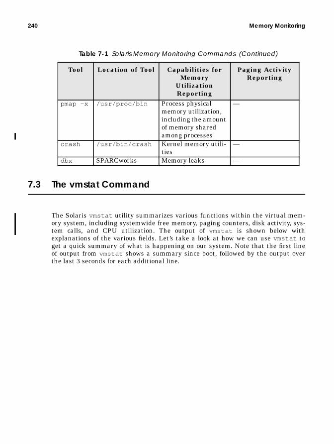
240 Memory Monitoring
7.3 The vmstat Command
The Solaris vmstat utility summarizes various functions within the virtual mem-ory system, including systemwide free memory, paging counters, disk activity, sys-tem calls, and CPU utilization. The output of vmstat is shown below withexplanations of the various fields. Let’s take a look at how we can use vmstat toget a quick summary of what is happening on our system. Note that the first lineof output from vmstat shows a summary since boot, followed by the output overthe last 3 seconds for each additional line.
pmap -x /usr/proc/bin Process physicalmemory utilization,including the amountof memory sharedamong processes
—
crash /usr/bin/crash Kernel memory utili-ties
—
dbx SPARCworks Memory leaks —
Table 7-1 Solaris Memory Monitoring Commands (Continued)
Tool Location of Tool Capabilities forMemory
UtilizationReporting
Paging ActivityReporting

The vmstat Command 241
7.3.1 Free Memory
Our vmstat example shows that we have 2,096 Kbytes of memory free, whichseems low for a system with 128 Mbytes. Recall from the introduction that freememory is low because the VM system has used all of it for file system caching,which means that free memory has fallen to approximately the value of lots-free . (See “The Page Scanner” on page 178 for the meaning of lotsfree .)Although free memory is almost zero, plenty of memory may still be available forapplications. We will look at how to observe how much of our memory is being usedfor file system caching when we later discuss MemTool in detail.
7.3.2 Swap Space
The vmstat command reports the amount of virtual swap space that is free andavailable for reservation. This is the sum of the total amount of physical swap
# vmstat 3 procs memory page disk faults cpu r b w swap free re mf pi po fr de sr f0 s2 s3 s4 in sy cs us sy id 0 0 0 42200 5312 0 12 126 40 135 0 0 0 2 2 2 242 4373 285 12 9 80 0 0 0 400952 3168 0 1 5 0 0 0 0 0 0 0 0 318 6584 319 11 3 86 0 1 0 401064 2616 4 74 466 168 210 0 0 0 0 0 0 545 6124 623 12 10 78 0 0 0 401096 2000 5 21 125 5 32 0 0 0 0 0 0 448 6521 375 18 8 74 0 0 0 400944 2096 0 6 0 45 82 0 0 0 0 0 0 252 6814 346 11 3 86
r = run queue lengthb = processes blocked waiting for I/Ow = idle processes that have been swapped at some time
swap = free and unreserved swap available, in Kbytesfree = free memory measured in pages
re = pages reclaimed from the free listmf = minor faults – the page was in memory but was not mappedpi = pages paged in from file system or swap devicepo = pages paged out to file system or swap devicefr = pages that have been destroyed or freedde = pages freed after writes
s0-s3 = disk I/Os per second for disk 0-3
in = interrupts/secondsy = system calls/secondcs = process context swtiches/second
us = user cpu timesy = kernel cpu timeid = idle+wait cpu time

242 Memory Monitoring
space available plus the amount of memory swap space. It is equivalent to the“available” column in swap -s .
7.3.3 Paging Counters
The vmstat paging counters show us the systemwide virtual memory pagingactivity. The counters include paging activity to/from program memory (anony-mous memory) and to/from file systems. The fields are shown in Table 7-2.
7.3.4 Process Memory Usage, ps, and the pmap Command
The memory usage of a process can be categorized into two classes: its virtualmemory usage and its physical memory usage. The virtual memory size is theamount of virtual address space that has been allocated to the process, and thephysical memory is the amount of real memory pages that has been allocated to aprocess. We refer to the physical memory usage of a process as its resident set size,
Table 7-2 Statistics from the vmstat Command
Counter Descriptionre Page reclaims — The number of pages reclaimed since the last
sample. Some of the file system cache is in the free list, andwhen a file page is reused and removed from the free list, areclaim occurs. File pages in the free list can be either regularfiles or executable/library pages.
mf Minor faults — The number of pages attached to an addressspace since the last sample. If the page is already in memory,then a minor fault simply reestablishes the mapping to it.
pi Page-ins — The number of pages paged in since the last sam-ple. A page-in occurs whenever a page is brought back in fromthe swap device or brought from a file system into the file sys-tem cache.
po Page-outs — The number of pages paged out and freed. Apage-out is counted whenever a page is written and freed.Often, this is as a result of the pageout scanner, fsflush, or fileclose.
fr Page frees — The number of pages that have been freed byeither the page scanner or by the file system (free behind).
de The precalculated, anticipated, short-term memory shortfall.Used by the page scanner to free ahead enough pages to sat-isfy requests.
sr The number of pages scanned by the page scanner per second.

The vmstat Command 243
often abbreviated RSS. We can use the ps command to display a process’s virtualand physical memory usage.
From the ps example, we can see that the /bin/sh shell uses 1,032 Kbytes of vir-tual memory, 768 Kbytes of which have been allocated from physical memory. Wecan also see that two shells are running. ps reports that both shells are using 768Kbytes of memory each, but in fact, because each shell uses dynamic shared librar-ies, the total amount of physical memory used by both shells is much less than768K x 2.
To ascertain how much memory is really being used by both shells, we need tolook more closely at the address space within each process. Figure 7.1 shows howthe two shells share both the /bin/sh binary and their shared libraries. The fig-ure shows each segment of memory within the shell’s address space. We’ve sepa-rated the memory use into three categories:
• Private — Memory that is mapped into each process and that is not sharedby any other processes.
• Shared — Memory that is shared with all other processes on the system,including read-only portions of the binary and libraries, otherwise known asthe “text” segments.
• Partially shared — A segment that is partly shared with other processes.The data segments of the binary and libraries are shared this way becausethey are shared but writable and within each process are private copies ofpages that have been modified. For example, the /bin/sh data segment ismapped shared between all instances of /bin/sh but is mapped read/writebecause it contains initialized variables that may be updated during the exe-cution of the process. Variable updates must be kept private to the process, soa private page is created by a “copy on write” operation. (See “Copy-on-Write”on page 152 for further information.)
# ps -e -opid,vsz,rss,args PID VSZ RSS COMMAND11896 1040 736 ps -a -opid,vsz,rss,args11892 1032 768 sh 3603 1032 768 sh 2695 1896 1432 telnet donan 2693 1920 1456 telnet donan 2433 1920 1440 telnet firefly 3143 1920 1456 telnet devnull 2429 1920 1440 telnet firefly.eng 2134 1920 1440 telnet devnull

244 Memory Monitoring
Figure 7.1 Process Private and Shared Mappings (/bin/sh Example)
/bin/sh – data
Heap
Stack
/bin/sh – text
libc_psr.so – text
libc.so – text
libc.so – data
libgen.so – text
libgen.so – data
libc_ut.so – text
libc_ut.so – data
libdl.so – text
libdl.so – private heap
ld.so – text
ld.so –data
/bin/sh – data
Heap
Stack
/bin/sh – text
libc_psr.so – text
libc.so – text
libc.so – data
libgen.so – text
libgen.so – data
libc_ut.so – text
libc_ut.so – data
libdl.so – text
libdl.so – private heap
ld.so – text
ld.so – data/usr/lib/ld.so
/usr/lib/dl.so
/usr/lib/libc_ut.so
/usr/lib/libgen.so
/usr/lib/libc.so
/usr/platform/../libc.so
/bin/sh
Private
PartiallyShared
Shared

MemTool: Unbundled Memory Tools 245
The pmap command provides a mechanism for a detailed look at a process’s mem-ory utilization. The pmap command can show how much memory is resident, howmuch of that is shared, and how much private memory a process has.
The example output from pmap shows the memory map of the /bin/sh command.At the top of the output are the executable text and data segments. All of the exe-cutable binary is shared with other processes because it is mapped read-only intoeach process. A small portion of the data segment is shared; some is privatebecause of copy-on-write (COW) operations.
The next segment in the address space is the heap space, or user applicationdata. This segment is 100 percent private to a process.
Following the heap space are the shared libraries. Each shared library has atext and data segment, which are like the executable text and data. Library text is100 percent shared, and library data is partially shared. At the bottom of the pro-cess dump is the stack, which, like the heap, is 100 percent private. A summary ofthe total virtual size, resident portion, and private memory is printed at the bot-tom.
7.4 MemTool: Unbundled Memory Tools
MemTool was developed to provide a more in-depth look at where memory hasbeen allocated on a Solaris system. Using these tools, we can find out where everypage of memory is, and in what proportions. MemTool is available as a download-able, unsupported package from Sun Engineering. Note that these tools are not
# /usr/proc/bin/pmap -x 1069
pmap -x $$4285: shAddress Kbytes Resident Shared Private Permissions Mapped File00010000 88 88 88 - read/exec sh00034000 16 16 - 16 read/write/exec sh00038000 8 8 - 8 read/write/exec [ heap ]FF270000 16 16 16 - read/exec libc_psr.so.1FF280000 656 608 600 8 read/exec libc.so.1FF332000 32 32 - 32 read/write/exec libc.so.1FF350000 24 24 24 - read/exec libgen.so.1FF364000 16 16 - 16 read/write/exec libgen.so.1FF370000 8 8 - 8 read/exec libc_ut.soFF380000 8 8 - 8 read/write/exec libc_ut.soFF390000 8 8 8 - read/exec libdl.so.1FF3A0000 8 8 - 8 read/write/exec [ anon ]FF3B0000 120 120 120 - read/exec ld.so.1FF3DC000 8 8 - 8 read/write/exec ld.so.1FFBEC000 16 16 - 16 read/write/exec [ stack ]-------- ------ ------ ------ ------total Kb 1032 984 856 128

246 Memory Monitoring
supported by the normal Sun support channels. The latest version of MemTool canbe found at http://www.solarisinternals.com .
7.4.1 MemTool Utilities
The MemTool package provides command-line, GUI, and character tools, as listedin Table 7-3.
7.4.2 Command-Line Tools
MemTool provides three command-line tools: prtmem , memps, and prtswap .
7.4.2.1 System Memory Summary: prtmem
The prtmem command shows a systemwide summary of memory utilization, cate-gorized into seven major groups. The output from the prtmem command is shownbelow; the rows are described in Table 7-4.
Table 7-3 MemTool Utilities
Tool Interface Descriptionmemps CLI Dumps process summary and file system cache
memory (-m).prtmem CLI Displays a systemwide summary of memory alloca-
tion.prtswap CLI Displays a systemwide detailed description of swap
allocation. Both virtual and physical swap alloca-tion are shown.
memtool GUI Is a comprehensive GUI for UFS and process mem-ory.
mem CUI Is a Curses interface for UFS and process memory.
# prtmem
Total memory: 241 MegabytesKernel Memory: 39 MegabytesApplication: 106 MegabytesExecutable & libs: 36 MegabytesFile Cache: 3 MegabytesFree, file cache: 58 MegabytesFree, free: 0 Megabytes
Table 7-4 prtmem Rows
Row DescriptionTotal memory The total amount of usable memory in the system minus
that used for low-level memory management.

MemTool: Unbundled Memory Tools 247
7.4.2.2 File System Cache Memory: memps -m
Memtool provides a list showing where the pool of filesystem cache memory hasbeen allocated, sorted by vnode . The list summarizes the size of each vnode in thefile system cache and, if possible, gives the real file name. If the real file name can-not be determined, then the device and inode number are printed for that vnode .
We can display the list of vnodes in file system cache with the memps -mcom-mand. Table 7-5 describes the columns.
Kernel Memory Memory used for the kernel executable, data structures,and kernel allocations, internal to the operating system.
Application Anonymous memory used by processes, typically heap,stack, and copy-on-write pages.
Executable & libs Executable and shared library pages that are mappedinto process address space.
File Cache File cache that is not on the free list.Free, file cache File system cache that has been placed on the free list.
This file cache memory still contains valid cache but willbe consumed from the free list when memory is needed.
Free, free Memory that is free and not associated with any files.
# memps -m
SunOS devhome 5.7 SunOS_Development sun4u 02/08/100
00:23:12 Size E/F Filename 10232k E /export/ws/local/netscape/netscape 5648k E /export/ws/dist/share/framemaker,v5.5.3/bin/sunxm.s5.sparc/maker5X.e 2944k F /home/rmc/.netscape/history.dat 2888k E /ws/on998-tools/SUNWspro/SC5.x/contrib/XEmacs20.3-b91/bin/sparc-sun- 2000k E /export/ws/dist/share/acroread,v3.01/Reader/sparcsolaris/lib/libXm.s 1648k E /usr/dt/lib/libXm.so.4 1400k E /usr/dt/lib/libXm.so.3 1392k E /usr/openwin/server/lib/libserverdps.so.5 928k E /export/ws/dist/share/acroread,v3.01/Reader/sparcsolaris/lib/libread 824k E /export/ws/dist/share/acroread,v3.01/Reader/sparcsolaris/bin/acrorea . . .
Table 7-4 prtmem Rows (Continued)
Row Description

248 Memory Monitoring
7.4.2.3 The prtswap Utility
The prtswap utility shows the three main states of swap and the way in whichthat state affects the virtual and physical swap configured.
7.4.3 The MemTool GUI
The MemTool GUI provides an easy method for invoking most of the functionalityof the MemTool command line interfaces. Invoke the GUI as the root user to see allof the process and file information.
Table 7-5 memps Columns
Column DescriptionSize The amount of physical memory in the file system cache
for this file.E/F If the VM system sees this file as an executable or
library, then E for executable is shown; otherwise, F forfile is shown.
Filename The file name if known; otherwise, the file systemmount point and inode number are shown.
# prtswap -l
Swap Reservations:--------------------------------------------------------------------------Total Virtual Swap Configured: 336MB =RAM Swap Configured: 159MBPhysical Swap Configured: + 177MB
Total Virtual Swap Reserved Against: 289MB =RAM Swap Reserved Against: 111MBPhysical Swap Reserved Against: + 177MB
Total Virtual Swap Unresv. & Avail. for Reservation: 47MB =Physical Swap Unresv. & Avail. for Reservations: 0MBRAM Swap Unresv. & Avail. for Reservations: + 47MB
Swap Allocations: (Reserved and Phys pages allocated)--------------------------------------------------------------------------Total Virtual Swap Configured: 336MBTotal Virtual Swap Allocated Against: 254MB
Physical Swap Utilization: (pages swapped out)--------------------------------------------------------------------------Physical Swap Free (should not be zero!): 42MB =Physical Swap Configured: 177MBPhysical Swap Used (pages swapped out): - 135MB
# /opt/RMCmem/bin/memtool &

MemTool: Unbundled Memory Tools 249
The MemTool GUI offers three basic modes: buffer cache memory, process mem-ory, and a process/buffer cache mapping matrix.
7.4.3.1 File System Cache Memory
The initial screen shows the contents of the file system cache. The file systemcache display shows each entry in the UFS file system cache. Figure 7.2 shows thefields; Table 7-6 describes them.
Figure 7.2 MemTool GUI: File System Cache Memory
The GUI displays only the largest 250 files. A status panel at the top of the dis-play shows the total amount of files and the number that have been displayed.

250 Memory Monitoring
7.4.3.2 Process Memory
The second mode of the MemTool GUI is the process memory display. Click on theProcess Memory checkbox at the left of the GUI to select this mode. The processmemory display shows the process table with a memory summary for each pro-cess. Each line of the process table is the same as the per-process summary fromthe pmap command. Figure 7.3 shows the fields; Table 7-7 describes them.
Table 7-6 MemTool Buffer Cache Fields
Field DescriptionResident The amount of physical memory that this file has associ-
ated with it.Used The amount of physical memory that this file has
mapped into a process segment or SEGMAP. Generally,the difference between this and the resident figure iswhat is on the free list associated with this file.
Shared The amount of memory that this file has in memory thatis shared with more than one process.
Pageins The amount of minor and major page-ins for this file.Pageouts The amount of page-outs for this file.Filename The file name if known; otherwise, the file system
mount point and inode number are shown.

MemTool: Unbundled Memory Tools 251
Table 7-7 MemTool Process Table Field
Field DescriptionPID Process ID of process.Virtual The virtual size of the process, including swapped-out
and unallocated memory.Resident The amount of physical memory that this process has,
including shared binaries, libraries, etc.
Figure 7.3 MemTool GUI: Process Memory

252 Memory Monitoring
To select the individual process map for a process, click on one of the processentries.
7.4.3.3 Process Matrix
The process matrix, Figure 7.4, shows the relationship between processes andmapped files. Across the top of the display is the list of processes that we viewed inthe process memory display, and down the side is a list of the files that are mappedinto these processes. Each column of the matrix shows the amount of memorymapped into that process for each file, with an extra row for the private memoryassociated with that process.
The matrix can be used to show the total memory usage of a group of processes.By default, the summary box at the top right-hand corner shows the memory usedby all of the processes displayed. We can select a group of processes with the leftmouse button and then summarize by pressing the Selection button at thetop-middle of the display. Selecting the All/Filt button returns the full display.
Shared The amount of memory that this process is sharing withanother process, that is, shared libraries, shared mem-ory, etc.
Private The amount of resident memory this process has that isnot shared with other processes. This figure is essen-tially Resident - Shared.
Process The full process name and arguments.
Table 7-7 MemTool Process Table Field (Continued)
Field Description

Other Memory Tools 253
Figure 7.4 MemTool GUI: Process/File Matrix
7.5 Other Memory Tools
Two other memory tools—Workspace Monitor (wsm) and memstat (an extendedvmstat )—provide additional information.
7.5.1 The Workspace Monitor Utility: WSM
Another good utility for monitor memory usage is the workspace monitor. It showsa live status of a processes memory map and lists the amount of memory that hasbeen read or written to in the sampled interval. This information is particularly

254 Memory Monitoring
useful for determining how much memory a process is using at any given instant.The wsm command is invoked against a single process.
The counters in the wsm utility are in units of pages.
7.5.2 An Extended vmstat Command: memstat
Additional paging statistics are provided in the Solaris 7 kernel. Later, in Solaris8, a new vmstat option (-p ) was added to examine these statistics. The statisticscan be observed on Solaris 7 with a simple command-line utility: memstat .
memstat shows the paging activity, page-ins, page-outs, and page-frees sepa-rated into three classes: file system paging, anonymous memory paging, and exe-cutable/shared library paging.
# wsm -p 732 -t 10
Read Write Mapped PROT Segment maker5X.exe(pid 683) Mon Jul 21 15:44:10 1997 235 0 782 (R-X) maker 10 11 36 (RWX) maker 207 384 2690 (RWX) Bss & Heap 14 0 74 (R-X) /usr/lib/libc.so.1 2 1 3 (RWX) /usr/lib/libc.so.1 0 1 1 (RWX) /dev/zero <or other device> 0 0 1 (R-X) /usr/lib/straddr.so 0 0 1 (RWX) /usr/lib/straddr.so 1 0 2 (R-X) /usr/platform/SUNW,Ultra-2/lib/libc_psr.so.1 1 0 1 (RWX) /dev/zero <or other device> 0 0 56 (R-X) /usr/lib/libnsl.so.1 0 0 4 (RWX) /usr/lib/libnsl.so.1 0 0 3 (RWX) /dev/zero <or other device> 0 0 2 (R-X) /usr/lib/libmp.so.2 0 0 1 (RWX) /usr/lib/libmp.so.2 0 0 9 (R-X) /usr/openwin/lib/libXext.so.0 0 0 1 (RWX) /usr/openwin/lib/libXext.so.0 26 0 54 (R-X) /usr/openwin/lib/libX11.so.4 2 1 3 (RWX) /usr/openwin/lib/libX11.so.4 0 0 4 (R-X) /usr/lib/libsocket.so.1 0 0 1 (RWX) /usr/lib/libsocket.so.1 0 0 1 (RWX) /dev/zero <or other device> 0 0 1 (R-X) /usr/lib/libdl.so.1 0 0 14 (R-X) /usr/lib/ld.so.1 2 0 2 (RWX) /usr/lib/ld.so.1 0 3 6 (RWX) Stack 500 401 3753 Totals

Other Memory Tools 255
The columns for the memstat command are described in Table 7-8.
Table 7-8 Statistics from the memstat Command
Counter Descriptionfree The amount of free memory as reported by vmstat , which
reports the combined size of the cache list and free list. Freememory on Solaris 7 may contain some of the file system cache.
# memstat 3
memory ---------- paging ----------- - executable - - anonymous - -- filesys -- --- cpu---
free re mf pi po fr de sr epi epo epf api apo apf fpi fpo fpf us sy wt id16128 8 0 341 1629 1677 0 18 0 0 0 0 0 0 341 1629 1677 4 35 34 2715184 12 0 354 1720 2434 0 437 0 0 2 0 85 88 354 1634 2344 1 19 35 4515152 6 0 160 1522 2541 0 490 0 0 16 0 85 114 160 1437 2410 2 20 40 3814968 19 0 162 1688 3285 0 698 0 0 18 0 168 181 162 1520 3085 1 29 34 3615184 23 192 242 2232 3573 0 595 0 0 16 0 128 149 242 2104 3408 2 27 33 3815704 8 0 194 480 581 0 53 0 0 0 0 0 0 194 480 581 1 16 46 3816192 16 15 202 189 189 0 0 0 0 0 0 0 0 202 189 189 1 11 41 4716976 4 54 200 40 40 0 0 0 0 0 0 0 0 200 40 40 1 16 37 4617376 1 83 194 2 2 0 0 0 0 0 0 0 0 194 2 2 2 14 39 44
free = free memory measured in pages
re = pages reclaimed from the free listmf = minor faults – the page was in memory but was not mappedpi = pages paged in from file system or swap devicepo = pages paged out to file system or swap devicefr = pages that have been destroyed or freedde = pages freed after writes
us = user cpu timesy = kernel cpu timewt = wait cpu time
Global Paging Counters
id = idle cpu time
epi = executable and library pages that are paged inepo = executable and library pages that are paged out (should be zero)epf = executable and library pages that are freed
Executable Paging Counters
api = anonymous pages that are paged in from swapapo = anonymous pages that are paged out to swapapf = anonymous pages that are freed
Anonymous Paging Counters
File Paging Counters
api = file pages that are paged inapo = file pages that are paged outapf = file pages that are freed
CPU Summary

256 Memory Monitoring
re Page reclaims — The number of pages reclaimed since the lastsample. Some of the file system cache is in the free list, andwhen a file page is reused and removed from the free list, areclaim occurs. File pages in the free list can be either regularfiles or executable/library pages.
mf Minor faults — The number of pages attached to an addressspace since the last sample. If the page is already in memory,then a minor fault simply reestablishes the mapping to it
pi Page-ins — The number of pages paged in since the last sam-ple. A page-in occurs whenever a page is brought back in fromthe swap device or brought from a file system into the file sys-tem cache.
po Page-outs — The number of pages paged out and freed. Apage-out will be counted whenever a page is written and freed,often as a result of the pageout scanner, fsflush, or file close.
fr Page-frees — The number of pages that have been freed byeither the page scanner or by the file system (free-behind).
de The precalculated anticipated short-term memory shortfall.Used by the page scanner to free ahead enough pages to satisfyrequests.
sr The number of pages scanned by the page scanner per second.epi Executable and library page-ins — The number of pages from
executable or shared library files paged in since the last sam-ple. An executable/library page-in occurs whenever a page forthe executable binary or shared library is brought back in fromthe file system.
epo Executable and library page-outs. Should be zero.epf Executable and library page-frees — The number of executable
and library pages that have been freed by the page scanner.api Anonymous memory page-ins — The number of anonymous
(application heap and stack) pages paged in from the swapdevice since the last sample.
apo Anonymous memory page-outs — The number of anonymous(application heap and stack) pages paged out to the swap devicesince the last sample.
apf Anonymous memory page-frees — The number of anonymous(application heap and stack) pages that have been freed, afterthey have been paged out.
Table 7-8 Statistics from the memstat Command (Continued)
Counter Description

Other Memory Tools 257
fpi Regular file page-ins — The number of pages from regular filespaged in since the last sample. A file page-in occurs whenever apage for a regular file is read in from the file system (part of thenormal file system read process).
fpo Regular file page-outs — The number of regular file pages thatwere paged out and freed, usually as a result of being paged outby the page scanner or by write free-behind (when free memoryis less than lotsfree + pages_before_pager ).
fpf Regular file page-frees — The number of regular file pages thatwere freed, usually as a result of being paged out by the pagescanner or by write free-behind (when free memory is less thanlotsfree + pages_before_pager ).
Table 7-8 Statistics from the memstat Command (Continued)
Counter Description

258 Memory Monitoring

Part Three
THREADS, PROCESSES,AND IPC
• The Solaris Multi-threaded Process Architecture• The Solaris Kernel Dispatcher• Interprocess Communication
259

260

8
THE SOLARISMULTITHREADED
PROCESSARCHITECTURE
The process was one of the two fundamental abstractions on which the origi-nal Unix system was built (the other was the file). Processes were the basic unit ofscheduling and execution on Unix systems. Traditional implementations providedfacilities for the creation, prioritization, scheduling, managing, and termination ofprocesses. Some primitive commands and utilities existed for process monitoring(e.g., the ps (1) command), and cryptic debugging facilities allowed for settingbreakpoints and stepping through process execution.
In this chapter, we discuss the Solaris process model, the process execution envi-ronment, and the multithreaded process architecture, including processes, light-weight processes, and kernel threads. We also cover other topics directly related tothe kernel’s process model: procfs, signals, process groups, and session manage-ment.
8.1 Introduction to Solaris Processes
The Solaris kernel provides support for an entity known as a process, and the ker-nel maintains a systemwide process table, whereby each process is uniquely identi-fied by a positive integer called the process identification number (PID). The ps (1)command provides a point-in-time snapshot, taken as specified by the ps (1) com-mand options, of the kernel’s process table, providing process names, PIDs, andother relevant data about the processes.
261

262 The Solaris Multithreaded Process Architecture
The Solaris process model is in some ways similar to the traditional Unix pro-cess model. At a high level, processes include the basic abstractions required forexecution, such as a hardware state and operating-system-maintained softwarecontext. The Solaris kernel considerably extends the traditional implementation ofoperating system process support by providing support for multiple threads of exe-cution within a single process, and each thread shares much of the process stateand can be scheduled and run on a processor independently of other threads in thesame process.
The current model is a two-level threads model that provides thread abstrac-tions at the kernel and user level. The goal of this two-level model is to allow forthe creation of hundreds or thousands of user threads within a single process witha minimum of overhead in the kernel. On multiprocessor hardware, this approachprovides the potential for fine-grained application concurrency that previouslyrequired multiple processes, which incur considerably more operating system over-head.
The process priority scheme and scheduling have been completely redesignedfrom prior implementations. The original Unix model provided a timesharingscheduling policy that essentially applied a round-robin approach to schedulingprocesses on processors so that there was a fairly even distribution of CPU time forall processes. The Solaris environment, however, implements scheduling classes,which define the policies and algorithms that the kernel applies to scheduling andexecution. For each scheduling class, there exists a table of values and parametersthe dispatcher code uses for selecting a thread to run on a processor; these tables,known as the dispatch tables, are discussed further in Chapter 9, “The Solaris Ker-nel Dispatcher”
In addition to the architectural changes, the level of sophistication of utilitiesand tools related to process management, monitoring, and debugging have evolvedconsiderably, due largely to the implementation and evolution of the process filesystem, procfs. Procfs is a pseudo file system that emerged with AT&T UNIX Sys-tem V Release 4 (SVR4). Procfs exports the kernel’s process model and underlyingabstractions to users, providing a file-like interface for the extraction of processdata, and facilities for process control and debugging. Procfs is covered in “Procfs— The Process File System” on page 306.
8.1.1 Architecture of a Process
Each process has a context and various items of state information that define theexecution environment of the process. All processes require memory in order tostore instructions (text), data, temporary processing space (heap), and stack. Thus,every process has an address space, which is a kernel abstraction for managing thememory pages allocated to the process. A process’s context can be further dividedinto a hardware and software context. The hardware context comprises the plat-form-specific components that define the process execution environment, such asthe hardware registers (general registers, stack pointer, stack frame pointer, etc.).The software context includes the process’s credentials (owner, group), opened files,

Introduction to Solaris Processes 263
identifiers, the address space, signal dispositions, signal handlers, and so forth.The basic process execution environment, minus the thread abstractions, is shownin Figure 8.1.
Figure 8.1 Process Execution Environment
Figure 8.1 shows the major components that establish the execution environmentfor a process. We introduce these abstractions here and discuss them in detail laterin the chapter.
The address space defines the mapped memory pages for a process’s variousaddress space segments. The identifiers maintained for each process include theprocess’s PID, the PID of its parent process, and the ID of the process group theprocess belongs to. Process groups provide a linkage for processes under control ofthe same terminal and facilitate things like job control signal delivery and man-agement, which are part of the session management abstraction.
Most processes have at least three opened files—commonly referred to as stan-dard input (stdin), standard output (stdout), and standard error (stderr)—thatdefine the source and destination of input and output character streams for theprocess. These file descriptors may link to device information for a controlling ter-minal or window or may represent a file in a file system. Signals provide a meansby which a process can be notified of an event or condition that may alter the exe-cution environment. All processes maintain signal masks, can alter the disposi-tion of one or more signals, and can define signal handlers for particular signals.Finally, there exists a means by which processes are assigned an execution prior-ity and scheduling class, which determine how much processor time the processwill get relative to other processes executing on the system.
kern
el p
roce
ss ta
ble
process
addressspace
process ID (PID)process group IDparent process ID
processlineage(parents,children)
hardwarecontext(registers,stack)
process state
sessioninformation(controlterminal,job controlstate)
signals,handlers,disposition
open files
scheduling class and priority
CPU(s)
Memory
I/O
credentials (UID, GID)

264 The Solaris Multithreaded Process Architecture
The process we show in Figure 8.1 is single threaded. In the Solaris kernel, sucha process has exactly one lightweight process (LWP) and kernel thread (kthread) inits address space. These are the kernel-level thread abstractions that are part ofthe two-level threads model. We didn’t show these structures in the figure becausewe wanted to illustrate the core abstractions that define the execution environ-ment, and the LWP and kthread are effectively transparent in a nonthreaded pro-cess. Now, we’ll add the additional components that are an integral part of thekernel’s multithreaded process architecture.
The actual implementation of lightweight processes and kernel threads are inthe form of kernel data structures that are linked to the process structure, form-ing the foundation for the threads design. This model isolates the kernel from userthreads, which are separate and distinct from kernel threads and LWPs. Userthreads are not visible to the kernel. More specifically, user threads are not visibleto the kernel as an executable entity that can be scheduled.
User threads are threads created explicitly as a result of a program calling thethr_create (3T) or pthread_create (3T) library routines (Solaris ships with 2thread’s libraries; libthread.so for Solaris threads, and libpthread.so for POSIXthreads). User threads have their own priority scheme that is separate and dis-tinct from the priority mechanism implemented by the kernel scheduler. Userthreads essentially schedule themselves by calling into the thread library dis-patcher and switch routines periodically at pre-defined preemption points. A userthread is scheduled from the thread library’s point of view by getting linked on toan available LWP. Recognizing this behavior is essential to understanding thepotential level of concurrency in a multithreaded program: The availability of anLWP is required for a user thread to execute, and LWPs are not created automati-cally when user threads are created. Instead the thread create call must explicitlyask the kernel to create an LWP.
In some texts, the LWP is referred to as a “virtual CPU,” by way of describingthe relationship of the LWP and the user thread. From a user thread’s point ofview, getting an LWP is as good as getting a CPU (which is not exactly the case,but it is one step closer).
The LWP and kernel thread are visible to the kernel; every LWP has a corre-sponding kernel thread. The reverse, however, is not always so; not every kernelthread has a corresponding LWP. The kernel itself is multithreaded and will cre-ate kernel threads that perform various operating-system-specific tasks—memorymanagement, STREAMS queue processing, scheduling, etc.—that execute as ker-nel threads not bound to a user process. However, all user and application pro-cesses (any process seen by means of the ps (1) command), that is not a system(kernel) created process, have the one-to-one relationship between kthreads andLWPs, without exception. Hence, some authors use “LWP” and “kthread” inter-changeably. More frequently, the term LWP is used to describe the LWP/kthreadcomponent of the process model, for brevity and simplicity. However, in this book,we differentiate the terms.

Introduction to Solaris Processes 265
Programmers can drive the ratio of LWPs to user threads in a couple of differ-ent ways. First, they can have the operating system create an LWP when thethread is created, by setting the appropriate flag, THR_NEW_LWP, in thethr_create (3T) call. Programmers can also bind the user thread to an LWP byusing the THR_BOUND flag, as follows.
The POSIX pthread_create (3T) equivalent is to set the contentionscopeattribute to PTHREAD_SCOPE_SYSTEM. A bound user thread retains its binding tothe LWP for its entire existence, in such a way that the LWP is not available to theuser threads scheduler for linking to a different user thread. Binding user threadsto LWPs offers a more predictable execution model for multithreaded programsbecause the user thread is linked to the kernel-level resource (an LWP) it requiresfor execution. The downside to the binding approach is longer thread create times,since the kernel creates an LWP/kthread along with the user thread in the threadcreate call. Moreover, the kernel has a larger pool of LWPs and kthreads to man-age. For threaded processes with a great many threads, creating all bound threadsmay have a negative performance impact.
The Solaris threads interface also provides a thr_setconcurrency (3T) rou-tine, which advises the kernel as to the number of concurrent threads the pro-grammer wishes to be executed. The POSIX library provides an equivalentpthread_setconcurrency (3T) interface. In the absence of the explicit creationof LWPs or concurrency advice from the programmer, the threads library attemptsto maintain a reasonable number of LWPs such that user threads have theresources they need to execute. The system attempts to maintain a balancebetween keeping too many idle LWPs around and not having enough LWPs. Theformer requires additional kernel overhead to manage; the latter results in runna-ble user threads waiting for a resource so they can execute. Solaris 2.5.1 (and priorreleases) used a signal mechanism to manage the LWP pool and create more LWPsfor a process with runnable user threads (more on this in “Signals” on page 324).Beginning in Solaris 2.6, a facility known as scheduler activations provides abidirectional communication channel between the user threads library and thekernel; this facility greatly improves the management of the LWP-to-user threadproblem.
Processes that are not explicitly multithreaded, meaning the code does not callone of the thread create interfaces, have a single LWP/kthread as part of theiraddress space, created by the kernel when the process is created. Users and devel-opers need not necessarily be aware of the multithreaded architecture of theSolaris environment and the additional kernel abstractions. The system providesthe traditional process model view in which the standard interfaces are used forprocess creation: the fork /exec model. In fact, all processes on a Solaris systemtoday are created through the fork and exec interfaces. The kernel silently cre-ates the LWP and kthread in new processes to support the low-level infrastruc-ture for process scheduling and management.
In the multithreaded process model, most of the process state and context isshared by all threads within a process. That is, the address space (mapped mem-

266 The Solaris Multithreaded Process Architecture
ory pages), credentials, open files, signal handlers, etc., are shared. However, eachthread has its own hardware context or machine state. The general registers, stackpointer, program counter, and frame pointer are specific to the thread of execution.Specifically, the LWP maintains a control structure that stores the hardware con-text (the registers) when a thread is context-switched off a processor, and providesthe register state loaded into the hardware registers when a thread is con-text-switched onto a processor for execution. Figure 8.2 illustrates the multi-threaded model.
Figure 8.2 The Multithreaded Process Model
The key point to be derived from examining Figure 8.2 is that the two-levelthreads design in the Solaris kernel offers thread abstractions at two levels. Userthreads are created with specific programming interfaces and are scheduled by aper-process scheduling thread in the threads library. The kernel dispatcher (sched-uler) schedules kernel threads. The linking of a user thread to a kernel thread(LWP—in this context, they can be thought of as a single entity) is required beforethe user thread becomes an executable entity that the kernel can schedule. Whenthe kernel thread/LWP the user thread is linked to is scheduled, the user threadexecutes.
proc
ess
proc
ess
software context:open files, credentials,address space,process group,session control,...
user
thre
ad
user
thre
ad
user
thre
ad
kernel dispatcherview
CPU
kthr
ead
LWP
mac
hine
stat
e
kthr
ead
LWP
mac
hine
stat
e
LWP
LWP
user
thre
ad
user
thre
ad
user
thre
ad
software context:open files, credentials,address space,process group,session control,...
Unbound user threadsare scheduled withinthe threads library,where the selecteduser thread is linkedto an available LWP.
kthr
ead
LWP
mac
hine
stat
e
kthr
ead
LWP
mac
hine
stat
e
LWP
LWP

Introduction to Solaris Processes 267
8.1.2 Process Image
We discuss the process image briefly before we dive into the discussion of datastructures and other kernel process-related topics, to provide a foundation that thesubsequent topics build on and to help keep the big picture in focus. The processimage, in this context, is the definition of what a process looks like when it isloaded in memory and ready for execution on a Solaris system. We also talk aboutthe format of the binary object file, the file’s on-disk image.
All processes begin life as programs, and programs are simply text files writtenin a computer programming language (that statement may seem something of anoversimplification these days, but it’s generally accurate). The program is com-piled and linked by the appropriate language-specific compiler. A successful compi-lation process results in the creation of an executable binary file on disk. This filebecomes a process in the Solaris environment through invocation of the exec (2)system call.
Once an executable object file is exec ’d, the runtime linker, ld.so.1 (1), isinvoked to manage linking to other shared objects required for execution, typicallya shared object library such as libc.so.1 . This sequence of events is known asdynamic linking, where references in the program to shared object library func-tions (e.g., printf (3), read (2), etc.) are resolved at runtime by ld.so.1 . It is pos-sible to build statically linked executables through a compilation flag (-B staticon the compile command line); this flag forces the inclusion of all referencedlibrary functions in the executable object at build time. This technique requiresthat an archive version of the library be available (e.g., libc.a for static linkingand libc.so.1 for dynamic linking). The building of applications using staticlinking is discouraged; in fact, it is not possible to build 64-bit executables inSolaris 7 that statically link to system libraries because no archive versions (.afiles) of the 64-bit objects ship with the release.
The format of the object file complies with the ELF file format, or Executableand Linking Format. There are two class definitions for the ELF file format, onefor 32-bit and one for 64-bit executables (ELFCLASS32and ELFCLASS64); Solaris 7provides support for both types of executables. Prior Solaris versions support32-bit executables only.
ELF provides format definitions for both the on-disk and execution (in-memory)image, shown in Figure 8.3. The ELF format is an industry standard, part of theSystem V Application Binary Interface (ABI) that defines an operating systeminterface for compiled, executable programs. Since the ABI defines the binaryinterface for several implementations of Unix System V across a variety of differ-ent hardware platforms, the ELF definition must be divided into two components:a platform-independent piece and a specification that is specific to a processor (e.g.,Sun SPARC V8, Sun SPARC V9, Intel x86, etc.). Areas of the ABI that are proces-sor specific include the definition of the function-calling sequence (system calls,stack management, etc.) and the operating system interface (signals, process ini-tialization). Our focus for the remainder of this section is on the object file format,
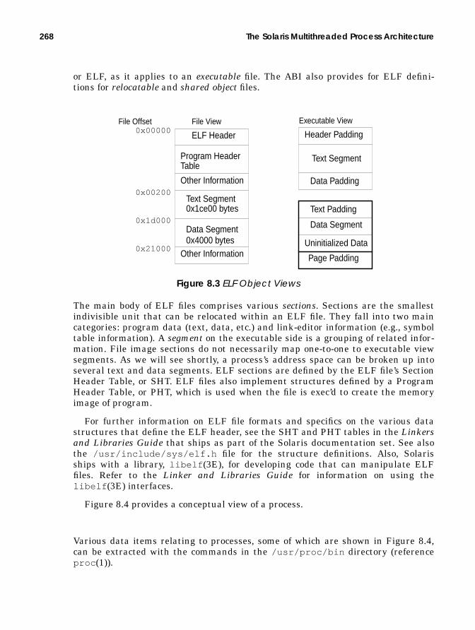
268 The Solaris Multithreaded Process Architecture
or ELF, as it applies to an executable file. The ABI also provides for ELF defini-tions for relocatable and shared object files.
Figure 8.3 ELF Object Views
The main body of ELF files comprises various sections. Sections are the smallestindivisible unit that can be relocated within an ELF file. They fall into two maincategories: program data (text, data, etc.) and link-editor information (e.g., symboltable information). A segment on the executable side is a grouping of related infor-mation. File image sections do not necessarily map one-to-one to executable viewsegments. As we will see shortly, a process’s address space can be broken up intoseveral text and data segments. ELF sections are defined by the ELF file’s SectionHeader Table, or SHT. ELF files also implement structures defined by a ProgramHeader Table, or PHT, which is used when the file is exec’d to create the memoryimage of program.
For further information on ELF file formats and specifics on the various datastructures that define the ELF header, see the SHT and PHT tables in the Linkersand Libraries Guide that ships as part of the Solaris documentation set. See alsothe /usr/include/sys/elf.h file for the structure definitions. Also, Solarisships with a library, libelf (3E), for developing code that can manipulate ELFfiles. Refer to the Linker and Libraries Guide for information on using thelibelf (3E) interfaces.
Figure 8.4 provides a conceptual view of a process.
Various data items relating to processes, some of which are shown in Figure 8.4,can be extracted with the commands in the /usr/proc/bin directory (referenceproc (1)).
File ViewFile Offset
ELF Header
Program HeaderTable
Other Information
Text Segment0x1ce00 bytes
Data Segment0x4000 bytes
Other Information
0x00000
0x00200
0x1d000
0x21000
Executable View
Header Padding
Text Segment
Data Segment
Data Padding
Text Padding
Uninitialized Data
Page Padding

Process Structures 269
To summarize the previous paragraphs: It is through the ELF file definition andformat that the kernel and associated tools (compiler and linker) create a disk filethat is an executable object which can be properly loaded into memory and turnedinto a process for scheduling and execution.
All of the process context, both hardware and software, is maintained in thedata structures described in the sections that follow.
8.2 Process Structures
In this section, we take a look at the major data structures that make up the mul-tithreaded process model in the Solaris kernel.
8.2.1 The Process Structure
The process structure, or proc structure, provides the framework for the creationand management of processes and threads in the Solaris environment. Figure 8.5illustrates the big picture, showing the process structure with most of the struc-ture members, along with all the other components that provide the entire processexecution environment.
addr
ess
spac
e virtual address0001000000022000ef7a2000ef7a8000ef7d0000effed000
mappinga.out fileheap spacelibc shared objanon spacelink editorstack
physical memory
memorypages
disk
Some processmemory pagesoriginate asdisk files.
proc
ess
hardwareregisters
Processor
hardwarecontextsaved in& restoredfrom structsin the LWP(mcontext)
virtual-to-physicaladdresstranslation
LWP
kthread
open filessignalscredentials...
Figure 8.4 Conceptual View of a Process

270 The Solaris Multithreaded Process Architecture
Figure 8.5 The Process Structure and Associated Data Structures
*p_exec*p_as*p_lockpp_crlock*p_credp_swapcntp_statp_wcodep_ppid*p_parent*p_child*p_pidp*p_pgidpp_utimep_stimep_cutimep_cstimep_brkbasep_brksizep_sig*p_sigqueue*p_sigqhdr
p_lwptotalp_zombcnt*p_tlist*p_zomblist*p_trace*p_plist
p_user
*p_aio*p_itimer*p_door_list*p_sc_door
vnodeplock
credentials
kthread
kthread
kthread
LWP
LWP
LWP
tsproc
tsproc
tsproc
hat
pid
proc group ID
inodethe on-diskbinary objectexecutablefile
the process structure
hardware addresstranslation.
Linked list of kernelthreads and LWPs. Eachkernel thread links to ascheduling class specificdata structure (e.g., tsproc).
segment
u_flist
file structuresvnodes
inodes
user
are
a
aio structure
*p_aslwptp
signal queuesignalheaders.
cpucpu structure of the cpu
segment
segment
segvn_data
segvn_data
segvn_data
anon_map
vnode pointersto vnode segmentis mapping tothe “aslwp”
thread forsignals
vnodescheduler activations door vnode.
door_node
vnodevnode vnode links to /proc
for primary vnode and/proc entry list
.
the thread last ran on
scheduling-class-specificdatastructures(cl_data)
addressspace
kernelthread

Process Structures 271
Like any kernel data structure, the members of the proc structure cover the fullrange of data types, including a great many pointers to support structures that, intotal, make up the entire process picture in the Solaris environment. In the follow-ing pages, we describe the major structure members and associated links. See alsothe header file /usr/include/sys/proc.h .
• p_exec — Pointer to a vnode . A process is often referred to as the execut-able form of a program. As such, all processes originate as binary files in a filesystem. When the file is exec’d, the kernel loads the binary ELF file intomemory. The p_exec pointer points to a vnode that ultimately links to theon-disk image of the file. The vnode structure is defined in/usr/include/sys/vnode.h .
• p_as — Address space structure pointer. All of the memory pages mapped toa process make up that process’s address space. The as structure, a kernelabstraction for managing the memory pages allocated to a process, definesthe process’s virtual address space (see Figure 8.6). You can dump theaddress space mappings of a process by using /usr/proc/bin/pmap .
Figure 8.6 Process Virtual Address Space
Below is sample output of the /usr/proc/bin/pmap command (with the -xflag), which dumps all the segments that make up a process’s virtual addressspace. The pmap(1) display provides the virtual address of the mapping(Address), the size of the mapping in Kbytes, how much of the mapping is res-ident in physical memory, how much is mapped shared, how much is mappedprivate, the permissions to the mapping, and the mapped file name. Note thatthe stack is mapped read/write/exec, as required for compliance with theSPARC V8 Application Binary Interface.There is a security exposure to mapping stack pages with exec permissionsbecause a system is subject to buffer overflow attacks, where rogue code posi-tions itself on a process’s stack, sets the program counter, and begins execut-ing instructions. You can set an /etc/system variable, called
text
heap
shared libs
stack
program text; the
memory work space
mapping for shared
mappings for stack
0x00000000
0xffffffff
data initialized data
0xffffffffffffffffff
0x0000000000000000
32-bit Solaris 64-bit Solaris 7
text
data
heap
shared libs
stack
reserved
libraries
executable code

272 The Solaris Multithreaded Process Architecture
no_exec_user_stack , to prevent the mapping of stack pages with executepermissions on Solaris 2.6 and Solaris 7. The entry in the /etc/system filewill look like:
set no_exec_user_stack = 1
Note that Solaris 2.5.1 does not include this tunable parameter. Here is anaddress space dump of a process on Solaris 2.6.
Here’s a pmap(1) dump of a 64-bit executable on a Solaris 7 system, completewith 64-bit addresses. For 64 bits, the SPARC V9 Application Binary Inter-face defines stack pages as read/write only, to block buffer overflow attacks.
• p_lockp — Process lock structure pointer. The p_lock is a kernel mutex(mutual exclusion) lock that synchronizes access to specific fields in the pro-cess structure (see Chapter 2, “Kernel Synchronization Primitives”). Thislevel of granularity of kernel lock increases parallelism because there is not a
$ /usr/proc/bin/pmap -x 2563925639: tpAddress Kbytes Resident Shared Private Permissions Mapped File00010000 8 8 8 - read/exec dev:193,2 ino:108916200020000 8 8 8 - read/write/exec dev:193,2 ino:108916200022000 1032 1032 - 1032 read/write/exec [ heap ]EF580000 1024 1024 - 1024 read/write/exec/shared [shmid=0x12d]EF6E0000 8 8 - 8 read/write/exec [anon]EF6F0000 16 16 16 - read/exec libc_psr.so.1EF700000 592 552 544 8 read/exec libc.so.1EF7A2000 24 24 8 16 read/write/exec libc.so.1EF7A8000 8 8 - 8 read/write/exec [anon]EF7A8000 8 8 - 8 read/write/exec [anon]EF7F8000 8 8 8 - read/write/exec ld.so.1EF7D0000 104 104 104 - read/exec ld.so.1EF7F8000 8 8 8 - read/write/exec ld.so.1EFBFE000 4104 4104 - 4104 read/write/exec [stack]-------- ------ ------ ------ ------total Kb 6944 6904 704 6200
$ /usr/proc/bin/pmap -x 99649964: mem 1048576Address Kbytes Resident Shared Private Permissions Mapped File0000000100000000 8 8 8 - read/exec mem0000000100100000 8 8 - 8 read/write/exec mem0000000100102000 1040 1032 - 1032 read/write/exec [ heap ]FFFFFFFF7F400000 696 576 416 160 read/exec libc.so.1FFFFFFFF7F5AC000 64 64 - 64 read/write/exec libc.so.1FFFFFFFF7F5BC000 8 8 - 8 read/write/exec [ anon ]FFFFFFFF7F680000 112 112 112 - read/exec ld.so.1FFFFFFFF7F79A000 16 16 - 16 read/write/exec ld.so.1FFFFFFFF7F7C0000 16 8 8 - read/exec libc_psr.so.1FFFFFFFF7F7E0000 8 8 - 8 read/write/exec [ anon ]FFFFFFFF7F7F0000 8 8 8 - read/exec libdl.so.1FFFFFFFF7FFFC000 16 16 - 16 read/write [ stack ]---------------- ------ ------ ------ ------ total Kb 2000 1864 552 1312
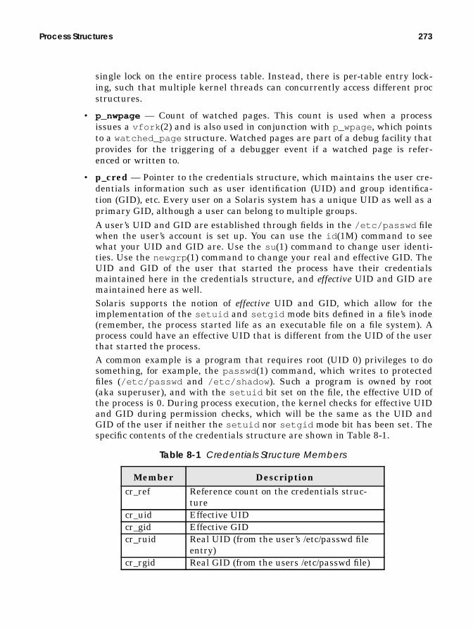
Process Structures 273
single lock on the entire process table. Instead, there is per-table entry lock-ing, such that multiple kernel threads can concurrently access different procstructures.
• p_nwpage — Count of watched pages. This count is used when a processissues a vfork (2) and is also used in conjunction with p_wpage , which pointsto a watched_page structure. Watched pages are part of a debug facility thatprovides for the triggering of a debugger event if a watched page is refer-enced or written to.
• p_cred — Pointer to the credentials structure, which maintains the user cre-dentials information such as user identification (UID) and group identifica-tion (GID), etc. Every user on a Solaris system has a unique UID as well as aprimary GID, although a user can belong to multiple groups.A user’s UID and GID are established through fields in the /etc/passwd filewhen the user’s account is set up. You can use the id (1M) command to seewhat your UID and GID are. Use the su (1) command to change user identi-ties. Use the newgrp (1) command to change your real and effective GID. TheUID and GID of the user that started the process have their credentialsmaintained here in the credentials structure, and effective UID and GID aremaintained here as well.Solaris supports the notion of effective UID and GID, which allow for theimplementation of the setuid and setgid mode bits defined in a file’s inode(remember, the process started life as an executable file on a file system). Aprocess could have an effective UID that is different from the UID of the userthat started the process.A common example is a program that requires root (UID 0) privileges to dosomething, for example, the passwd (1) command, which writes to protectedfiles (/etc/passwd and /etc/shadow ). Such a program is owned by root(aka superuser), and with the setuid bit set on the file, the effective UID ofthe process is 0. During process execution, the kernel checks for effective UIDand GID during permission checks, which will be the same as the UID andGID of the user if neither the setuid nor setgid mode bit has been set. Thespecific contents of the credentials structure are shown in Table 8-1.
Table 8-1 Credentials Structure Members
Member Descriptioncr_ref Reference count on the credentials struc-
turecr_uid Effective UIDcr_gid Effective GIDcr_ruid Real UID (from the user’s /etc/passwd file
entry)cr_rgid Real GID (from the users /etc/passwd file)

274 The Solaris Multithreaded Process Architecture
• p_crlock — Kernel mutex to synchronize access to the credentials structure.
• p_swpcnt — Counter of LWPs linked to the process that have been swappedout. Under severe memory shortfalls, the memory scheduler (PID 0, thesched process) will swap out entire LWPs to free up some memory pages.
• p_stat — The process status, or state. The notion of process states is some-what misleading in the Solaris environment, since the kernel thread, not theprocess, is the entity that gets a scheduling class, is prioritized, and is put ona dispatch queue for scheduling. Kernel threads change state in the Solarisenvironment much more frequently than do processes. For a nonthreadedprocess, the process state is essentially whatever the state of the kthread is.For multithreaded processes, several kthreads that belong to the same pro-cess can be in different states (e.g., running, sleeping, runnable, zombie, etc.).In a few areas in the kernel, the process state (p_stat ) is used explicitly. Inthe fork() code, during process creation, the SIDL state is set, and later infork , p_stat is set to SRUN—the process has been created and is runnable.In the exit() code, pstat is set to ZOMBwhen a process is terminated.Those three exceptions aside, all other state changes during the lifetime of aprocess occur in the kthread and are reflected in the state field in thekthread structure. In fact, the state (S) column from the ps (1) command isderived from the kthread state field, not the process p_stat data. If a pro-cess has more than one LWP and the -L flag has not been specified on theps (1) command line, then the state field is derived from LWP 1 (the -L flagto ps (1) will print information about each LWP in each selected process). Aprocess can be in one of the following possible states:
• SLEEP — Process is sleeping (waiting for an event)
• RUN — Process is runnable, waiting to be scheduled
• ZOMB— Process is a zombie, that is, it has exited but a wait has not yetexecuted on its behalf
• STOP — Process is stopped, typically because of debugger activity
cr_suid Saved UID (in case UID changes acrossexec)
cr_sgid Saved GID, as abovecr_ngroups Number of supplementary groupscr_groups[] Array of supplementary groups; the size of
the array is maintained in cr_ngroups ,and the maximum number of groups a usercan belong is limited to 16
Table 8-1 Credentials Structure Members
Member Description

Process Structures 275
• SIDL — Process is being created and is assigned this interim state
• ONPROC — Process is running on a processor
Process states and state transitions are shown in Figure 8.7.
Figure 8.7 Process State Diagram
• p_wcode — Defined as current wait code. A synchronization field that con-tains data to support SIGCLD (child signal) information. A process is sent aSIGCLD signal when the status of one of its child processes has changed. Thep_wcode holds a status bit that identifies the reason for the status change(e.g., child has exited, stopped, coredumped, was killed, or has continued).
• p_pidflag — Another field used to support synchronization via signals. Sta-tus bits to indicate a SIGCLD signal is pending or a SIGCLD was sent to notifythe parent that the child process has continued (see “Signals” on page 324).
• p_wdata — Also used for process synchronization with signals and used inconjunction with p_wcode ; contains status bits that provide a reason for anevent. For example, if a process is killed by a SIGKILL signal, the p_wcodewill indicate the child was killed and the p_wdata will indicate a SIGKILLsignal was the reason (see “Signals” on page 324).
• p_ppid — The process’s parent process ID.
Many of the process structure fields defined above are covered in more detail as wemove through other process-related information in the remainder of this chapter.
The process model in the Solaris kernel maintains a lineage for all the pro-cesses running on the system. That is, every process has a parent process and mayhave child processes. The process creation model, in which a new process beginslife as the result of an existing process issuing some variant of the fork (2) systemcall, means that, by definition, there will minimally be a parent process to thenewly created process. Not only will a process have a parent, but it may also havesiblings—processes that have been created by the same parent. Every process inthe Solaris environment can reside on as many as a dozen or so linked lists main-
SSTOP
SSLEEP
SIDL SRUN SONPROC
SZOMB
fork()
wait()
debugger
syscall
preempted or time quantum used
exit, fall through main, signal, etc.
fork complete
wakeup
or job control

276 The Solaris Multithreaded Process Architecture
tained by the kernel; the proc structure stores the various pointers required. All ofthe process structure members described below are pointers to a process structure.
• p_parent — Pointer to the parent process.
• p_child — Pointer to the first child process. Subsequent children are linkedby means of the sibling pointers in the child processes.
• p_sibling — Pointer to the first sibling (next child created by parent).
• p_psibling — Pointer to previous sibling. Back pointer in support of a dou-bly linked list of related processes.
• p_sibling_ns — Pointer to a sibling process that has changed state.
• p_child_ns — Pointer to a child process that has changed state.
• p_next — Next process in the active process list. The kernel maintains adoubly linked list of active processes in the system, pointed to by the kernelpractive pointer.
• p_prev — Previous process in the active process list (see above).
• p_nextofkin — Link maintained back to parent process. Used in processexit code to gather accounting information (accumulated user time and sys-tem time). Also used to set orphan pointers when a process exits. The orphanlinks of an exiting process are linked to the nextofkin process, which is theparent.
• p_orphan — Orphan pointer. An orphan process lost its parent; that is, anorphan process continues executing after its parent has exited. In the forkcode, the p_orphan pointer in the parent is set to point to the newly createdchild. Processes without children have a NULL p_orphan pointer. If child pro-cesses spawn other child processes, p_orphan will link to the “grandchil-dren” should the parent terminate.
• p_nextorph — Next orphan pointer. In fork , the newly created child pro-cess’s p_nextorph pointer is set to the p_orphan pointer in the parent.Essentially, p_nextorph links siblings.
• p_pglink — Process group link. Forward link to a hash chain of processes inthe same process group. Processes are linked in a group when they are con-trolled by the same controlling terminal. See “Sessions and Process Groups”on page 342.
• p_ppglink — Previous process group link. Back link to hash chain of pro-cesses in the same process group.
Figure 8.8 illustrates how the process lineage pointers are set up with a test pro-gram, bd, written for that purpose. The processes shown depict process bd, whichfork/execs three child processes, c1, c2, and c3. The c2 process fork/execs its ownchild (process cc2), as does the c3 process (child name cc3). The cc3 child process

Process Structures 277
also fork/execs a child, ccc3. So, we end up with a reasonably realistic process hier-archy that we can use for illustration.
Figure 8.8 Process Lineage Pointers
In Figure 8.8, pointers without connecting lines are NULL. The linked pointers canbe summarized as follows. The parent and child pointers are (we hope) straightfor-ward. The bd process parent pointer links to the shell that spawned it (notshown), the child pointer links to c3, the last child created (chronologically),nextofkin links to the parent, and orphan links to the last child created, c3. Thethree children, c1, c2, and c3, of the bd process link to each other through the sib-ling and psibling pointers, forming a linked list of all the children spawned by
parentchildsiblingpsiblingnextofkinorphannextorph
parentchildsiblingpsiblingnextofkinorphannextorph
parentchildsiblingpsiblingnextofkinorphannextorph
parentchildsiblingpsiblingnextofkinorphannextorph
parentchildsiblingpsiblingnextofkinorphannextorph
parentchildsiblingpsiblingnextofkinorphannextorph
parentchildsiblingpsiblingnextofkinorphannextorph
bd
c1 c2 c3
cc2 cc3
ccc3
links backto the shellprocess
bd (fork/exec)
c1
c2 (fork/exec) -> cc2
c3 (fork/exec) -> cc3 (f/e) -> ccc3
next
-of-k
in p
oint
ers,
refe
renc
ing
the
pare
nt

278 The Solaris Multithreaded Process Architecture
the same parent (bd). The nextofkin pointer in all three child processes links tothe parent, bd.
The cc2, cc3, and ccc3 processes have no siblings: thus, the sibling pointersare NULL. They link back to the parent through the parent and nextofkin point-ers. And of course, the parent/child links between the cc3 and ccc3 processes roundout the picture.
The way the picture changes if a process dies is due in part to how the code isconstructed. In this example, the bd process was blocking in a waitpid (2) call,waiting on the PID of the c3 process. We killed process c3, which resulted in bdand c3 both terminating, leaving c1, c2, cc2, cc3, and ccc3. The parent andnextofkin pointers in c1, c2, and cc3 linked to the init process, which inheritsorphan processes. The sibling pointers in c1 and c2 changed, where sibling inc1 linked to c2, and psibling in c2 linked back to c1.
Additional pointers maintained in the proc structure include the following:
• p_sessp — Pointer to a session structure, which contains information formanaging the process’s control terminal. See “Sessions and Process Groups”on page 342.
• p_pidp — Pointer to a pid structure, for process ID (PID) information. Theprocess’s actual PID is stored in one of the fields in the pid structure.
• p_pgpidp — Another pid structure pointer, for process group information(process group ID).
The Solaris kernel maintains a data structure for managing PIDs and processgroup IDs (Figure 8.9).
Figure 8.9 PID Structure
The first 4 bytes of the PID structure store 2 status bits, pid_prinactive andpid_pgorphaned , followed by 6 pad bits (unused bits) and 24 bits to store the slotnumber of the /proc table entry for the process, pid_prslot . Since we use 24bits to store the unique /proc table entry for processes, we have a limit of 16 mil-lion possible /proc table entries. This limit will never actually be reached in
pid_prinactive:1pid_pgorphaned:1pid_padding:6
pid_prslot:24pidt_t pid_id;struct proc *pid_pglink;struct pid * pid_link;u_int pid_ref;

Process Structures 279
Solaris versions up to and including Solaris 7 because the kernel defines a MAXPIDvalue of 30,000. The limit of 30,000 processes is imposed by the use of a 2-bytedata type in the utmp structure.
The kernel maintains a /var/adm/utmp and /var/adm/wtmp file for the stor-age of user information used by the who(1), write (1), and login (1) commands(the accounting software and commands use utmp and wtmp as well). The PIDdata is maintained in a signed short data type, which has a maximum value of32,000. This “limit” should in no way be construed as a problem; 30,000 is a greatmany processes and our largest installations today do not have anywhere nearthat many processes running. See “The Kernel Process Table” on page 290 for adescription of how the actual systemwide process limits are established.
The PID structure links to other PID structures in the kernel throughpid_link , which maintains a hashed list of active PIDs in the kernel, andpid_pglink , which links back to the process structure. Finally, the prinactivebit flags the structure as being free or used, and pgorphaned indicates whetherthe process is orphaned (the parent has exited or died—orphaned processes areadopted by the init process).
Several condition variables are maintained in the proc structure. Conditionvariables are a kernel synchronization mechanism used to notify a process orthread if a specific event, such as the completion of an I/O, has occurred. Condi-tion variables are used in the Solaris environment to implement sleep andwakeup. One such condition variable is p_holdlwps, a special condition variable forholding process LWPs. In a fork() , the LWPs must be suspended at some point sotheir kernel stacks can be cloned for the new process.
In the process structure, the kernel maintains time totals that reflect the amountof user time and system time the process accumulated, as well as summations forall the child processes system time and user time. The child information issummed when a child process exits. The p_utime and p_stime fields maintainthe process’s user and system time, respectively; the p_cutime and p_cstimefields maintain the child process’s user and system time.
The process maintains several bits of information on LWPs and kernel threads,including a total of all LWPs linked to the process (p_lwpcnt ) and all LWPs cre-ated, p_lwptotal . The latter may be different from p_lwpcnt because the kernelmay have allocated LWPs to the process from the systemwide pool. Such LWPs willnot have been explicitly created by the process. Counters are maintained for thenumber of blocked LWPs (p_lwpblocked ), runnable LWPs (p_lwprcnt ), andzombie LWPs (p_zombcnt ). A pointer rooted in the proc structure references alinked list of kernel threads (p_tlist) and a linked list of zombie threads(p_zomblist ). (A zombie process is a process that has exited but whose parentprocess did not issue a wait call to retrieve the exit status.)
The remaining members of the process structure can be grouped into several cate-gories. Per-process signal handling support involves linking to signal queue struc-tures, supporting the signal mask and signal posting structures. The Solaris signal
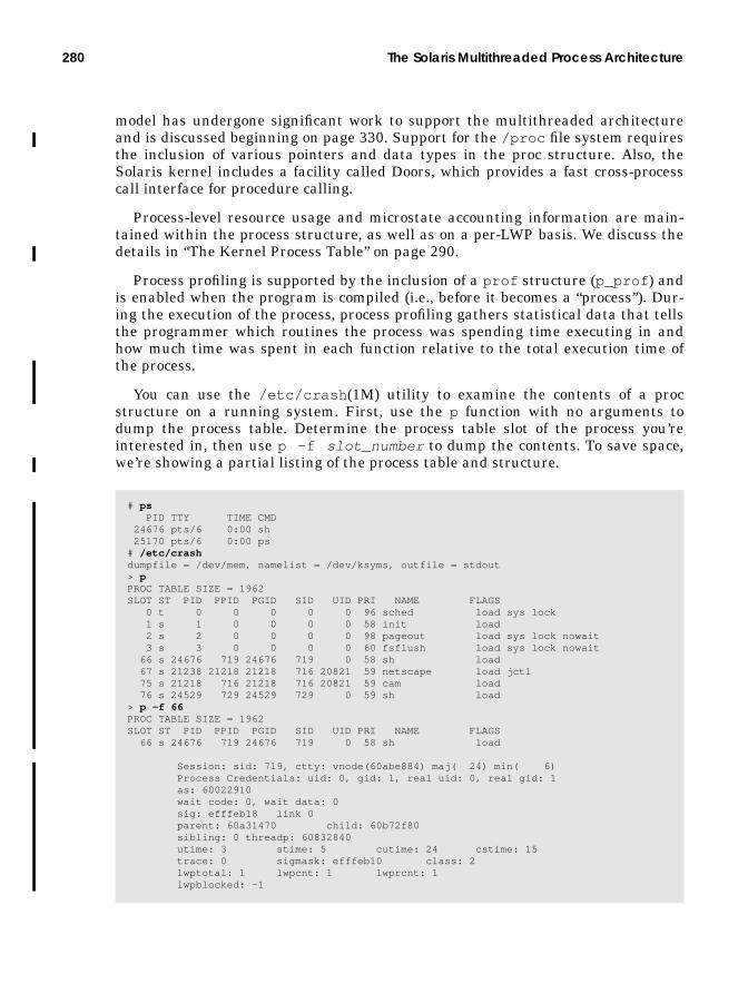
280 The Solaris Multithreaded Process Architecture
model has undergone significant work to support the multithreaded architectureand is discussed beginning on page 330. Support for the /proc file system requiresthe inclusion of various pointers and data types in the proc structure. Also, theSolaris kernel includes a facility called Doors, which provides a fast cross-processcall interface for procedure calling.
Process-level resource usage and microstate accounting information are main-tained within the process structure, as well as on a per-LWP basis. We discuss thedetails in “The Kernel Process Table” on page 290.
Process profiling is supported by the inclusion of a prof structure (p_prof ) andis enabled when the program is compiled (i.e., before it becomes a “process”). Dur-ing the execution of the process, process profiling gathers statistical data that tellsthe programmer which routines the process was spending time executing in andhow much time was spent in each function relative to the total execution time ofthe process.
You can use the /etc/crash (1M) utility to examine the contents of a procstructure on a running system. First, use the p function with no arguments todump the process table. Determine the process table slot of the process you’reinterested in, then use p -f slot_number to dump the contents. To save space,we’re showing a partial listing of the process table and structure.
# ps PID TTY TIME CMD 24676 pts/6 0:00 sh 25170 pts/6 0:00 ps# /etc/crashdumpfile = /dev/mem, namelist = /dev/ksyms, outfile = stdout> pPROC TABLE SIZE = 1962SLOT ST PID PPID PGID SID UID PRI NAME FLAGS 0 t 0 0 0 0 0 96 sched load sys lock 1 s 1 0 0 0 0 58 init load 2 s 2 0 0 0 0 98 pageout load sys lock nowait 3 s 3 0 0 0 0 60 fsflush load sys lock nowait 66 s 24676 719 24676 719 0 58 sh load 67 s 21238 21218 21218 716 20821 59 netscape load jctl 75 s 21218 716 21218 716 20821 59 cam load 76 s 24529 729 24529 729 0 59 sh load> p -f 66PROC TABLE SIZE = 1962SLOT ST PID PPID PGID SID UID PRI NAME FLAGS 66 s 24676 719 24676 719 0 58 sh load
Session: sid: 719, ctty: vnode(60abe884) maj( 24) min( 6) Process Credentials: uid: 0, gid: 1, real uid: 0, real gid: 1 as: 60022910 wait code: 0, wait data: 0 sig: efffeb18 link 0 parent: 60a31470 child: 60b72f80 sibling: 0 threadp: 60832840 utime: 3 stime: 5 cutime: 24 cstime: 15 trace: 0 sigmask: efffeb10 class: 2 lwptotal: 1 lwpcnt: 1 lwprcnt: 1 lwpblocked: -1

Process Structures 281
In the above example, we used ps (1), determined the PID of our shell process,invoked the crash utility, and used the p function to get the process table slot (66,in this case). Then, to dump the proc structure for process PID 24676, we againused the p utility, with the -f flag and the process table slot number.
8.2.2 The User Area
The role of the user area (traditionally referred to as the uarea), has changedsomewhat in the Solaris environment when compared with traditional implemen-tations of Unix. The uarea was linked to the proc structure through a pointer andthus was a separate data structure. The uarea was swappable if the process wasnot executing and memory space was tight. Today, the uarea is embedded in theprocess structure—it is not maintained as a separate structure. The process ker-nel stack, which was traditionally maintained in the uarea , is now implementedin the LWP (see “The Lightweight Process (LWP)” on page 285). The interestingbits in the uarea are listed below in the relative order in which they appear in the/usr/include/sys/user.h ).
• u_execid — The magic number (file type) of the on-disk executable that wasloaded with an exec (2) system call.
• u_execsz — The size of the executable file.
• u_tsize — Size of the text segment of the process address space.
• u_dsize — Size of the data segment of the process address space.
• u_start — Time when the process started, set when the process is first cre-ated, just after the start time is set in p_mstart .
• u_ticks — Total execution time in clock ticks of the process. When account-ing is turned on, written to the accounting file on exit. A clock tick variesacross processor types. On UltraSPARC-based systems, there are 100 ticksper second.
• u_exdata — Embedded exdata structure. Executable file information, suchas text, data, heap, shared library size, magic number, etc.
• u_psargs[] — Array of arguments passed to exec .
• u_comm[] — User command string when process was invoked.
• u_argc , u_argv , u_envp — The number of command-line arguments(u_argc ), a pointer to the array of command-line arguments (u_argv ), and apointer to the array of environmental variables (u_envp ). These are the vari-ables passed to the main() program function; they must be declared in everyprogram written to execute on the Solaris system, as set up by the compilerwhen code is generated to run.
• u_cdir — Pointer to the vnode for the current directory.
• u_rdir — Pointer to the root vnode . Not used unless chroot (2) is called.
• u_ttyvp — Pointer to vnode for controlling tty.

282 The Solaris Multithreaded Process Architecture
• u_cmask — File creation mask. Defines default file modes when files are cre-ated.
• u_mem— Memory usage. Updated in the clock handler for the active threadon each processor.
• u_nshmseg — Number of attached shared memory segments.
• u_rlimit[] — Array of rlimit structures that defines the resource limitsfor the process. The system imposes a total of seven resource limits. Eachresource limit has a current value and maximum value (also referred to as asoft limit and a hard limit), maintained as rlim_cur and rlim_max in therlimit structure. In Solaris releases up to and including Solaris 2.5.1,rlim_cur and rlim_max are 32-bit data types. Beginning in Solaris 2.6,there’s a 64-bit version of the rlimit structure, and rlim_cur andrlim_max are 64-bit data types.
The system defines a maximum value for each type, which is effectively themaximum attainable value for the data types. The actual value isn’t reallysignificant in most cases because the value is sufficiently large that an “infi-nite” resource limit is implied, which is essentially no limit. When we use theterm “infinite” in describing resource limits below, we mean the maximumvalue for a 64-bit data type. (In case you’re interested, the max value for asigned 64-bit data type is 9,223,372,036,854,775,807, or 9 exabytes. Anunsigned 64-bit data type has a maximum value of18,446,744,073,709,551,615, or 18 exabytes. Now you know why we considerlimits set at these values “virtually unlimited”!)In Solaris releases up to and including Solaris 2.6, a process’s resource limitswere changed with limit (1) or ulimit (2), which affected only the runningprocess (a shell, typically) and whatever children were spawned. In Solaris 7,a plimit (1) command was added, which allows you to change resource lim-its in other processes by specifying a PID on the command line. The followinglist describes each of the resource limits.
• CPU – Maximum CPU time in seconds. Default soft and hard limit isthe same; 4 billion for pre-2.6 releases, infinite for release 2.6 andbeyond. The clock interrupt handler tests for this limit, and sends aSIGXCPU signal if the limit is reached.
• FSIZE – Maximum file size, in 512 byte blocks. Same default values asCPU. The file system write code (the wrip() function in UFS) tests forthis limit and sends a SIGXFSZ signal to the process if the limit isreached.
• DATA – Maximum size of the process data segment. Default soft limitis 2 Gbytes, hard limit is 4 billion for pre-2.6 releases. In Solaris 2.7,infinite for soft and hard limit. Hitting this limit can cause a ENOMEMerror if a memory allocation routine (e.g., malloc() ) is called.
• STACK – Maximum size of the process stack segment. Default soft limit

Process Structures 283
is 8 Mbytes, hard limit is 2 Gbytes in Solaris 2.6. In Solaris 2.7, thehard limit is infinite on UltraSPARC-based systems, 2 Gbytes on allothers.
• CORE – Maximum core file size. Soft and hard limit is infinite. A valueof 0 here prevents the creation of a core file.
• NOFILE – Maximum number of open files. Default soft limit is 64, hardlimit is 1024.
• VMEM – Maximum address space. Infinite soft and hard limit. In real-ity, 4 Gbytes is the maximum virtual address space attainable on allSolaris releases up to and including Solaris 2.6. Solaris 7 provides a64-bit address space when booted as a 64-bit kernel, running a 64-bitbinary. The Sun UltraSPARC-I and UltraSPARC-II 64-bit processorsimplement a 44-bit virtual address, allowing for a maximum virtualaddress space of 16 terabytes.
The uarea is where process open file information is maintained, in the form of anarray of uf_entry structures. Each structure contains three elements: a pointer(uf_ofile ) to the file’s file structure, a 2-byte member for file flag bits(uf_pofile ), and a reference count (uf_refcnt ). A pointer, u_flist , is set topoint to the first element in the array (the first uf_entry structure), and thearray is indexed with the file descriptor number, or fd . An open file in a process isuniquely identified with an fd , which is a positive integer value returned by a suc-cessful call to open (2). Allocations of uf_entry structures are done in groups of24 (the NFPCHUNK variable in /usr/include/sys/user.h ).
Solaris 7 (SunOS 5.7) adds a structure pointer to the uf_entry structure:uf_fpollinfo , which is a pointer to an fpollinfo structure. Solaris 7 also addsnew functionality in the form of a poll cache to enhance support of the poll (2) sys-tem call. The kernel uses the poll cache to track process file descriptors that arebeing polled. The fpollinfo structure supports the poll cache implementation.
The following members of the uarea support management of the process’s openfile table:
• u_flock — A kernel mutex lock to synchronize access to the process open filelist.
• u_nofiles — Number of open file slots (i.e., number of open files in the pro-cess).
• u_flist — Pointer to the first uf_entry structure. Structure storage isimplemented as an array, indexed by the fd (file descriptor) number.
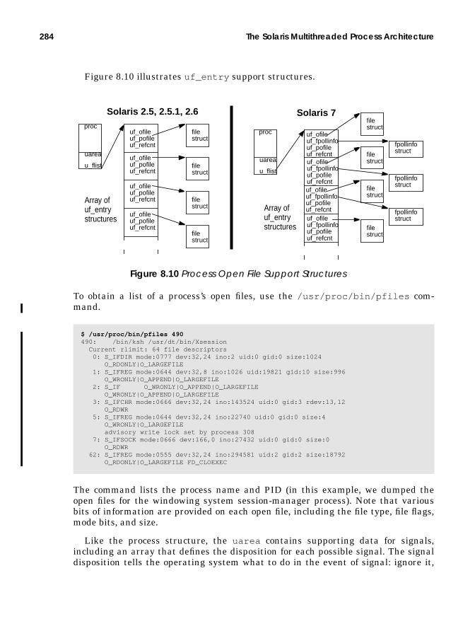
284 The Solaris Multithreaded Process Architecture
Figure 8.10 illustrates uf_entry support structures.
Figure 8.10 Process Open File Support Structures
To obtain a list of a process’s open files, use the /usr/proc/bin/pfiles com-mand.
The command lists the process name and PID (in this example, we dumped theopen files for the windowing system session-manager process). Note that variousbits of information are provided on each open file, including the file type, file flags,mode bits, and size.
Like the process structure, the uarea contains supporting data for signals,including an array that defines the disposition for each possible signal. The signaldisposition tells the operating system what to do in the event of signal: ignore it,
$ /usr/proc/bin/pfiles 490490: /bin/ksh /usr/dt/bin/Xsession Current rlimit: 64 file descriptors 0: S_IFDIR mode:0777 dev:32,24 ino:2 uid:0 gid:0 size:1024 O_RDONLY|O_LARGEFILE 1: S_IFREG mode:0644 dev:32,8 ino:1026 uid:19821 gid:10 size:996 O_WRONLY|O_APPEND|O_LARGEFILE 2: S_IF O_WRONLY|O_APPEND|O_LARGEFILE O_WRONLY|O_APPEND|O_LARGEFILE 3: S_IFCHR mode:0666 dev:32,24 ino:143524 uid:0 gid:3 rdev:13,12 O_RDWR 5: S_IFREG mode:0644 dev:32,24 ino:22740 uid:0 gid:0 size:4 O_WRONLY|O_LARGEFILE advisory write lock set by process 308 7: S_IFSOCK mode:0666 dev:166,0 ino:27432 uid:0 gid:0 size:0 O_RDWR 62: S_IFREG mode:0555 dev:32,24 ino:294581 uid:2 gid:2 size:18792 O_RDONLY|O_LARGEFILE FD_CLOEXEC
proc
uarea
u_flist
uf_ofileuf_pofileuf_refcnt
uf_ofileuf_pofileuf_refcnt
uf_ofileuf_pofileuf_refcnt
uf_ofileuf_pofileuf_refcnt
filestruct
proc
uarea
u_flist filestruct
filestruct
filestruct
Solaris 2.5, 2.5.1, 2.6 Solaris 7
uf_ofileuf_fpollinfouf_pofileuf_refcntuf_ofileuf_fpollinfouf_pofileuf_refcntuf_ofileuf_fpollinfouf_pofileuf_refcntuf_ofileuf_fpollinfouf_pofileuf_refcnt
filestruct
filestruct
filestruct
filestruct
fpollinfostruct
fpollinfostruct
fpollinfostruct
Array ofuf_entrystructures
Array ofuf_entrystructures

Process Structures 285
catch it and invoke a user-defined signal handler, or take the default action. See“Signals” on page 324.
The /etc/crash utility provides a function, shown below, for dumping a pro-cess’s uarea .
In the preceding example, we omitted the up-front dumping of the process table(the p function) to select a process’s uarea to dump. The u function takes a pro-cess table slot number as an argument, slot 19 in this case (the Xsession process,the same one we used in the previous pfiles example). Note the rather large val-ues in the resource limits. This example was done on a Solaris 2.6 system, whichincluded 64-bit data types for the rlimits.
8.2.3 The Lightweight Process (LWP)
The LWP structure is defined in /usr/include/sys/klwp.h . The kernel main-tains resource utilization counters and microstate accounting information forevery LWP. The sum total of all LWPs resource usage is stored in the process whenthe LWP exits. See “The Kernel Process Table” on page 290.
# /etc/crashdumpfile = /dev/mem, namelist = /dev/ksyms, outfile = stdout> u 67PER PROCESS USER AREA FOR PROCESS 67PROCESS MISC: command: crash, psargs: /etc/crash start: Fri May 5 21:37:41 2000 mem: 4cf9, type: exec vnode of current directory: f64769c0OPEN FILES, POFILE FLAGS, AND THREAD REFCNT: [0]: F 0xf6407cd0, 0, 0 [1]: F 0xf6407cd0, 0, 0 [2]: F 0xf6407cd0, 0, 0 [3]: F 0xf65695a8, 0, 0 [4]: F 0xf65696c0, 0, 0 [5]: F 0xf6569300, 0, 1 [6]: F 0xf6569b98, 0, 0 cmask: 0022RESOURCE LIMITS: cpu time: 18446744073709551613/18446744073709551613 file size: 18446744073709551613/18446744073709551613 swap size: 2147479552/18446744073709551613 stack size: 8388608/2147479552 coredump size: 18446744073709551613/18446744073709551613 file descriptors: 64/1024 address space: 18446744073709551613/18446744073709551613SIGNAL DISPOSITION: 1: default 2: ef638914 3: default 4: default 5: default 6: default 7: default 8: default 9: default 10: default 11: default 12: default 13: default 14: default 15: default 16: default 17: default 18: default 19: default 20: default 21: default 22: default 23: default 24: default 25: default 26: default 27: ignore 28: default 29: default 30: default 31: default 32: default 33: default 34: default 35: default 36: default 37: default 38: default 39: default 40: default 41: default 42: default 43: default 44: default 45: default

286 The Solaris Multithreaded Process Architecture
Other interesting information maintained in the LWP include the following:
• lwp_pcb — The hardware context data for the LWP, called a process controlblock (pcb). It contains various bits of machine state information that aresaved when the LWP is switched out and restored when it is switched backin. This is the machine state represented in Figure 8.2.
• lwp_ap — Pointer to the arglist passed in a system call.• lwp_errno — Error number for current system call.• lwp_error — Return value for current system call.• lwp_eosys — End-of-syscall action. Used for post-system-call handling and
for special conditions, such as profiling and process tracing.• lwp_watchtrap — Supports debugger single-step operations.• lwp_regs — Pointer to registers saved on the stack.• lwp_fpu — Pointer to floating point unit (fpu) registers.
Most of the above LWP structure members exist to support system calls and tomaintain hardware context information. Remember, system calls are function callsinto the kernel—a process’s way of asking the operating system to do something onits behalf (e.g., open/read/write a file, get my PID, etc). Since LWPs can be sched-uled on processors (along with their corresponding kernel thread) independently ofother LWPs in the same process, they need to be able to execute system calls onbehalf of the thread they’re bound to. An LWP blocked on a system call does notcause the entire process to block (as long as it’s a multithreaded process). SeeChapter 2 for details on system call processing.
The following LWP fields handle signals and debugging through the /procinterfaces.
• lwp_cursig — Current signal.• lwp_asleep — LWP sleeping in system call.• lwp_sigaltstack — Alternate signal stack specified.• lwp_curinfo — Pointer to a sigqueue , signal information for current sig-
nal.• lwp_siginfo — Signal information for stop-on-fault.• lwp_sigoldmask — Snapshot of signal mask for sig-suspend .• lwp_scall_start — Start time of system call.• lwp_utime — Time LWP spent running in user mode.• lwp_stime — Time LWP spent running in system (kernel) mode.• lwp_thread — Pointer to the associated kernel thread. Every LWP has a
corresponding kernel thread.• lwp_procp — Pointer to the proc structure.
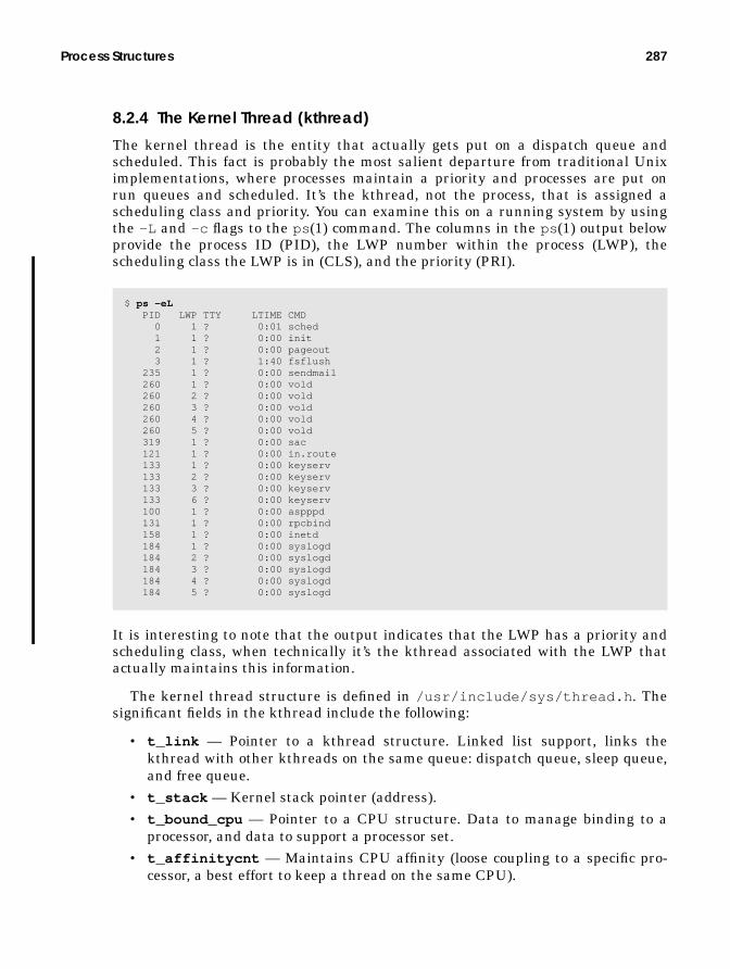
Process Structures 287
8.2.4 The Kernel Thread (kthread)
The kernel thread is the entity that actually gets put on a dispatch queue andscheduled. This fact is probably the most salient departure from traditional Uniximplementations, where processes maintain a priority and processes are put onrun queues and scheduled. It’s the kthread, not the process, that is assigned ascheduling class and priority. You can examine this on a running system by usingthe -L and -c flags to the ps (1) command. The columns in the ps (1) output belowprovide the process ID (PID), the LWP number within the process (LWP), thescheduling class the LWP is in (CLS), and the priority (PRI).
It is interesting to note that the output indicates that the LWP has a priority andscheduling class, when technically it’s the kthread associated with the LWP thatactually maintains this information.
The kernel thread structure is defined in /usr/include/sys/thread.h . Thesignificant fields in the kthread include the following:
• t_link — Pointer to a kthread structure. Linked list support, links thekthread with other kthreads on the same queue: dispatch queue, sleep queue,and free queue.
• t_stack — Kernel stack pointer (address).• t_bound_cpu — Pointer to a CPU structure. Data to manage binding to a
processor, and data to support a processor set.• t_affinitycnt — Maintains CPU affinity (loose coupling to a specific pro-
cessor, a best effort to keep a thread on the same CPU).
$ ps -eL PID LWP TTY LTIME CMD 0 1 ? 0:01 sched 1 1 ? 0:00 init 2 1 ? 0:00 pageout 3 1 ? 1:40 fsflush 235 1 ? 0:00 sendmail 260 1 ? 0:00 vold 260 2 ? 0:00 vold 260 3 ? 0:00 vold 260 4 ? 0:00 vold 260 5 ? 0:00 vold 319 1 ? 0:00 sac 121 1 ? 0:00 in.route 133 1 ? 0:00 keyserv 133 2 ? 0:00 keyserv 133 3 ? 0:00 keyserv 133 6 ? 0:00 keyserv 100 1 ? 0:00 aspppd 131 1 ? 0:00 rpcbind 158 1 ? 0:00 inetd 184 1 ? 0:00 syslogd 184 2 ? 0:00 syslogd 184 3 ? 0:00 syslogd 184 4 ? 0:00 syslogd 184 5 ? 0:00 syslogd

288 The Solaris Multithreaded Process Architecture
• t_bind_cpu — User-specified CPU binding (i.e., pbind (2)).• t_flag — Thread flag bits. Thread flags provide the kernel with a method of
setting and tracking necessary bits of information about the thread, such aswhether the thread is an interrupt thread, whether it is blocking, whether itscorresponding LWP is in a zombie state, etc.
• t_proc_flag — Additional thread flag bits. The distinction between thesebits and the ones in t_flag above are locking requirements. Only theT_WAKEABLEflag in t_flag requires a synchronization lock for setting orchecking since it must coincide with the thread state. The bits int_proc_flag are set and checked under protection of the p_lock , the ker-nel mutex that synchronizes access to the proc structure.
• t_schedflag — Flags the dispatcher uses for scheduling. They indicate con-ditions such as the thread is in memory, the thread should not be swapped,the thread is on a swap queue. The dispatcher also uses these flags to changethe thread’s state to runnable.
• t_preempt — Flag used to specify that thread should not be preempted.• t_state — Thread state. Any one of the following:
• TS_FREE – Free thread structure.
• TS_SLEEP – Sleeping on an event.
• TS_RUN – Runnable, waiting for a processor.
• TS_ONPROC – Thread is running on a processor.
• TS_ZOMB – Thread has exited, but not yet been reaped.
• TS_STOPPED – Thread is stopped. Initial thread state, possiblethrough a debugger as well.
The description of the process table showed that a process state field is main-tained in the process structure along with the kernel thread. The kernelthread, not the process, changes during execution. There is, for the most part,a correlation between states defined for the process and kernel thread states,as shown in Table 8-2.
Table 8-2 Kernel Thread and Process States
Process Kernel Thread DescriptionSIDL State during fork (2) (creation).SRUN TS_RUN Runnable.SONPROC TS_ONPROC Running on a processor.SSLEEP TS_SLEEP Sleeping (blocked).SSTOP TS_STOPPED Stopped.SZOMB TS_ZOMB Kthread/process has terminated.
TS_FREE Thread is waiting to be reaped.

Process Structures 289
The disparities in the state of a process and kernel thread have to do withprocess creation (process SIDL state) and the state of a kernel thread follow-ing termination (TS_FREE). We discuss this subject in the sections on processcreation and termination.
• t_pri — The thread’s scheduling priority.• t_epri — The thread’s inherited priority. Used for the implementation of
priority inheritance, which addresses the priority inversion problem.• t_wchan0 , t_wchan — Wait channel. What the thread is blocking on.• t_cid — Scheduling class ID (e.g., TS, RT).• t_cldata — Pointer to a scheduling-class-specific data structure.• t_clfuncs — Pointer to scheduling-class operations vector.• t_cpu — Pointer to a CPU structure for the CPU that the thread last ran on.• t_sigqueue — Pointer to a siginfo structure. Root pointer of siginfo
queue.• t_sig — Signals pending to this thread.• t_hold — Signal hold bit mask.• t_forw — Kthread pointer, forward link for linked list, processwide.• t_back — Kthread pointer, backward pointer for above.• t_lwp — Pointer to the LWP structure.• t_procp — Pointer to the proc structure.• t_next — Forward pointer for systemwide linked list of kernel threads.• t_prev — Back pointer for above.• t_cred — Pointer to current credentials structure.• t_sysnum — System call number.
The following kernel thread members are used by the dispatcher code for threadscheduling.
• t_lockp — Pointer to dispatcher lock.• t_oldspl — The previous priority level.• t_pre_sys — Flag for system call preprocessing.• t_disp_queue — Pointer to the thread’s dispatch queue.• t_disp_time — Last time this thread was running.• t_kpri_req — Kernel priority required for this thread.
The next group of kthread members deals with post-system-call or post-trap han-dling. The kthread members are embedded in the kthread structure as a union. Abit set in any of these members prevents a direct return to user mode of the threaduntil the condition has been satisfied.

290 The Solaris Multithreaded Process Architecture
• _t_astflag — Flag to indicate post-trap processing required, such as signalhandling or a preemption.
• _t_sig_check — Signal pending.• _t_post_syscall — Some post-system-call processing is required.• _t_trapret — Invokes the scheduling class-specific trap return code.
Figure 8.11 provides the big picture. Obviously, not every pointer implemented isshown. We wanted to provide a visual representation of how the major data struc-tures link together and in general to illustrate what a subsection of a typical pro-cess/lwp/kthread list looks like from a coarse-grained view.
Figure 8.11 The Process, LWP, and Kernel Thread Structure Linkage
8.3 The Kernel Process Table
Every process occupies a slot in the kernel process table, which maintains a pro-cess structure (commonly abbreviated as proc structure) for the process. The pro-cess structure is relatively large, about 900 bytes in size, and contains all theinformation the kernel needs to manage the process and schedule the LWPs andkthreads for execution. As processes are created, kernel memory space for the pro-cess table is allocated dynamically by the kmem cache allocation and managementroutines.
uarea
proc
uarea
proc
uarea
proc
uarea
proc
uarea
procpractive
LWP
kthr
ead
the kernel process table
LWP
kthr
ead
LWPkt
hrea
dLWP
kthr
ead
LWP
kthr
ead
LWP
kthr
ead
LWP
kthr
ead
LWP
kthr
ead
user threads

The Kernel Process Table 291
8.3.1 Process Limits
At system boot time, the kernel initializes a process_cache , which begins theallocation of kernel memory for storing the process table. Initially, space is allo-cated for one proc structure. The table itself is implemented as a doubly linked list,such that each proc structure contains a pointer to the next process and previousprocesses on the list. The maximum size of the process table is based on theamount of physical memory (RAM) in the system and is established at boot time.During startup, the kernel sets a tunable parameter, maxusers , to the number ofmegabytes of memory installed on the system, up to a maximum of 2,048. Thus,systems with more than 2 Gbytes of physical memory will have a maxusers valueof 2048. Systems with less than 2 Gbytes set maxusers to the amount of physicalmemory in megabytes; for example, a system with 512 Mbytes of RAM will have amaxusers value of 512. The maxusers value subsequently determines the amountof several major kernel resources, such as the maximum process table size and themaximum number of processes per user.
The formula is quite simple:
The max_nprocs value is the maximum number of processes systemwide, andmaxuprc determines the maximum number of processes a non-root user can haveoccupying a process table slot at any time. The system actually uses a data struc-ture, the var structure, which holds generic system configuration information, tostore these values in. There are three related values:
• v_proc , which is set equal to max_nprocs .• v_maxupttl , which is the maximum number of process slots that can be
used by all non-root users on the system. It is set to max_nprocs minus somenumber of reserved process slots (currently reserved_procs is 5).
• v_maxup , the maximum number of process slots a non-root user can occupy.It is set to the maxuprc value. Note that v_maxup (an individual non-rootuser) and v_maxupttl (total of all non-root users on the system) end upbeing set to the same value, which is max_nprocs minus 5.
max_nprocs = (10 + 16 * maxusers)maxuprc = (max_nprocs - 5)
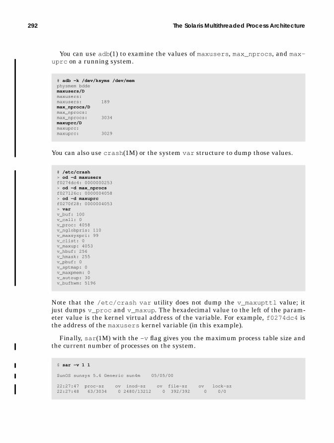
292 The Solaris Multithreaded Process Architecture
You can use adb (1) to examine the values of maxusers , max_nprocs , and max-uprc on a running system.
You can also use crash (1M) or the system var structure to dump those values.
Note that the /etc/crash var utility does not dump the v_maxupttl value; itjust dumps v_proc and v_maxup . The hexadecimal value to the left of the param-eter value is the kernel virtual address of the variable. For example, f0274dc4 isthe address of the maxusers kernel variable (in this example).
Finally, sar (1M) with the -v flag gives you the maximum process table size andthe current number of processes on the system.
# adb -k /dev/ksyms /dev/memphysmem bddemaxusers/Dmaxusers:maxusers: 189max_nprocs/Dmax_nprocs:max_nprocs: 3034maxuprc/Dmaxuprc:maxuprc: 3029
# /etc/crash> od -d maxusersf0274dc4: 0000000253> od -d max_nprocsf027126c: 0000004058> od -d maxuprcf0270f28: 0000004053> varv_buf: 100v_call: 0v_proc: 4058v_nglobpris: 110v_maxsyspri: 99v_clist: 0v_maxup: 4053v_hbuf: 256v_hmask: 255v_pbuf: 0v_sptmap: 0v_maxpmem: 0v_autoup: 30v_bufhwm: 5196
$ sar -v 1 1
SunOS sunsys 5.6 Generic sun4m 05/05/00
22:27:47 proc-sz ov inod-sz ov file-sz ov lock-sz22:27:48 63/3034 0 2480/13212 0 392/392 0 0/0

Process Creation 293
Under the proc-sz column, the 72/1962 values represent the current number ofprocesses (72) and the maximum number of processes (1962).
The kernel does impose a maximum value in case max_nprocs is set in/etc/system to something beyond what is reasonable, even for a large system. InSolaris releases 2.4, 2.5, 2.5.1, 2.6, and 7, the maximum is 30,000, which is deter-mined by the MAXPID macro in the param.h header file (available in/usr/include/sys ).
In the kernel fork code, the current number of processes is checked against thev_proc parameter. If the limit is reached, the system produces an “out of pro-cesses” message on the console and increments the proc table overflow countermaintained in the cpu_sysinfo structure. This value is reflected in the ov col-umn to the right of proc-sz in the sar (1M) output. For non-root users, a check ismade against the v_maxup parameter, and an “out of per-user processes for uid(UID)” message is logged. In both cases, the calling program would get a -1 returnvalue from fork (2), signifying an error.
8.3.2 LWP Limits
Now that we’ve examined the limits the kernel imposes on the number of pro-cesses systemwide, let’s look at the limits on the maximum number ofLWP/kthread pairs that can exist in the system at any one time.
Each LWP has a kernel stack, allocated out of the segkp kernel address spacesegment. The size of the kernel segkp segment and the space allocated for LWPkernel stacks vary according to the kernel release and the hardware platform. OnUltraSPARC (sun4u)-based systems running a 32-bit kernel, the segkp size is lim-ited to 512 Mbytes and the kernel stacks are 16 Kbytes. Thus, the maximum num-ber of LWPs systemwide is 32,768 (32K) (512-Mbyte segkp segment size and16-Kbyte stack size). On 64-bit Solaris 7, the larger (24-Kbyte) LWP kernel stackallocation reduces the total number of LWPs on an UltraSPARC-based system to21,845.
On non-UltraSPARC-based systems, the stack allocation is slightly smaller—12Kbytes. The kernel segkp segment is also smaller; the total size is based on thehardware architecture and amount of physical memory on the system.
8.4 Process Creation
All processes in Solaris are created with the traditional fork/exec Unix processcreation model that was part of the original Unix design and is still implementedin virtually every version of Unix in existence today. The only exceptions in theSolaris environment are the creation of four system daemons at startup, PIDs 0through 3: the memory scheduler (sched, PID 0), init (PID 1), the pageout dae-

294 The Solaris Multithreaded Process Architecture
mon (PID 2), and fsflush (PID 3). These processes are created by an internalkernel newproc() function. The mechanics of process creation are illustrated inFigure 8.12.
Figure 8.12 Process Creation
The fork (2) and exec (2) system calls are used extensively in the various softwarecomponents that come bundled with Solaris as well as in hundreds of applicationsthat run on Solaris. (However, more and more Solaris daemons and applicationsare being threaded with each release, which means that the programs use threadsas an alternative to multiple processes.)
The fork (2) system call creates a new process. The newly created process isassigned a unique process identification (PID) and is a child of the process thatcalled fork ; the calling process is the parent. The exec (2) system call overlays theprocess with an executable specified as a path name in the first argument to theexec (2) call. The model, in pseudocode format, looks like this:
The pseudocode above calls fork (2) and checks the return value from fork (2)(pid). Remember, once fork (2) executes successfully, there are two processes: forkreturns a value of 0 to the child process and returns the PID of the child to theparent process. In the example, we called exec (2) to execute new_binary once in
main(int argc, char *argv[], char *envp[]){ pid_t child_pid; child_pid = fork(); if (child_pid == -1) perror(RforkS); /* fork system call failed */ else if (child_pid == 0) execv(R/path/new_binaryS,argv); /* in the child, so exec */ else wait() /* pid > 0, weUre in the parent */}
main(){
pid_t pid;pid=fork()if (pid == 0)
exec(program)else if (pid > 0)
wait()..
}
parent process child process
disk blockswith executable
exec loads objectinto child procaddress space.new
programtext,data,etc.
Process Creation 295
the child. Back in the parent, we simply wait for the child to complete (we’ll getback later to this notion of “waiting”).
A couple of different flavors of fork (2) that are available take different codepaths in the process creation flow. The traditional fork (2) call duplicates theentire parent process, including all the threads and LWPs that exist within theprocess when the fork (2) is executed.
With Solaris 2.X and threads support came a variant of fork (2): fork1 (2). Inthe fork1 (2) call, only the thread that issues the fork1 (2) call and its associatedsupport structures are replicated. This call is extremely useful for multithreadedprograms that also do process creation because it reduces the overhead of replicat-ing potentially tens or hundreds of threads in the child process. If an exec (2) callis planned following the fork (2), as is typically the case, the exec (2) code will freeall but one LWP/kthread, which makes the use of fork (2) somewhat superfluousin a multithreaded process. Note that linking fork to a particular threads librarymodifies fork ’s behavior. Linking with the Solaris threads library (-lthread com-pilation flag) results in the described replicate-all fork (2) behavior. Linking withthe POSIX threads library (-lpthread ) results in a call to fork (2) replicatingonly the calling thread. In other words, linking with -lpthread (POSIX threadslibrary) and calling fork (2) results in fork1 (2) behavior.
Finally, there’s vfork (2), which is described as a “virtual memory efficient” ver-sion of fork . A call to vfork (2) results in the child process “borrowing” theaddress space of the parent, rather than the kernel duplicating the parent’saddress space for the child, as it does in fork (2) and fork1 (2). The child’s addressspace following a vfork (2) is the same address space as that of the parent. Moreprecisely, the physical memory pages of the new process’s (the child) address spaceare the same memory pages as for the parent. The implication here is that thechild must not change any state while executing in the parent’s address spaceuntil the child either exits or executes an exec (2) system call—once an exec (2)call is executed, the child gets its own address space. In fork (2) and fork1 (2), theaddress space of the parent is copied for the child by means of the kernel addressspace duplicate routine (the kernel as_dup() ).
For some applications, the use of vfork (2) instead of fork (2) can improve appli-cation efficiency noticeably. Applications that fork/exec a lot of processes (e.g., mailservers, Web servers) do not incur the overhead of having the kernel create and setup a new address space and all the underlying segments with each fork (2) call.Rather, address spaces are built as needed following the exec (2) call.
The kernel code flow for process creation is represented in the followingpseudocode.

296 The Solaris Multithreaded Process Architecture
fork() or fork1() or vfork()cfork()getproc() Get proc structure (via kmem_cache_alloc(process_cache)). Set process state (p_stat) to SIDL. Set process start time (p_mstart). Call pid_assign() to get PID. pid_assign(). Get a pid structure. Get a /proc directory slot. Get an available PID. init the PID structure. Set reference count. Set PID. Set proc slot number. Return pid to getproc().Check for process table overflow (procs > v.v_nprocs).Check for per-user process limit reached.Put new process on process table linked list.Set new process p_ignore and p_signal from parent.Set the following fields in new (child) process from parent. Session stucture pointer p_sessp. Executable vnode pointer p_exec. Address space fields p_brkbase, p_brksize, p_stksize. Set child parent PID. Set parent-child-sibling pointers. Copy profile state from parent to child, p_prof.Increment reference counts in open file list(child inherits these).Copy parent’s uarea to child (includes copying open file list).if (child inherits /proc tracing flag (SPRFORK set in p_flag) Set p_sigmask in child from parent. Set p_fltmask in child from parent.else Clear p_sigmask and p_fltmask in child (set to emtpy).if (inherit microstate accounting flag in parent) Enable microstate accounting in childReturn from getproc() to cfork().if (vfork()) Set child address space to parent (child p_as = parent p_as). Set child SVFORK in p_flag.else (not a vfork()) Duplicate copy of parent’s address space for child (as_dup()) Duplicate parent’s shared memory for child.Duplicate parent LWPs and kthreads. if (fork1()) Just duplicate the current thread. forklwp() lwp_create() else (walk the process thread list - p_tlist; for each thread) forklwp() lwp_create() - create an LWP Replicate scheduling class from parent thread_create() - create a kernel threadAdd the child to the parent’s process group (pgjoin())Set the child process state (p_stat) to SRUNif (vfork()) Increment cpu_sysinfo vfork count (cpu_sysinfo.sysvfork) Call continuelwps() for child execution before parentelse Increment cpu_sysinfo fork count (cpu_sysinfo.sysfork) Place child in front of parent on dispatch queue (so it runs first).Set return values: PID to parent, 0 to child

Process Creation 297
As the preceding pseudocode flow indicates, when the fork (2) system call isentered, a process table slot is allocated in kernel memory: the process_cache,which was first implemented in Solaris 2.6. (In prior Solaris versions, the kernelsimply grabbed a chunk of kernel memory for a process structure.) The processstart-time field (p_mstart ) is set, and the process state is set to SIDL , which is astate flag to indicate the process is in an intermediate “creation” state. The kernelthen assigns a PID to the process and allocates an available slot in the /procdirectory for the procfs entry. The kernel copies the process session data to thechild, in the form of the session structure; this procedure maintains the sessionleader process and controlling terminal information. The kernel also establishes heprocess structure pointer linkage between the parent and child, and the uarea ofthe parent process is copied into the newly created child process structure.
The Solaris kernel implements an interesting throttle here in the event of a pro-cess forking out of control and thus consuming an inordinate amount of systemresources. A failure by the kernel pid_assign() code, which is where the newprocess PID is acquired, or a lack of an available process table slot indicates alarge amount of process creation activity. In this circumstance, the kernel imple-ments a delay mechanism by which the process that issued the fork call is forcedto sleep for an extra clock tick (a tick is every 10 milliseconds). By implementingthis mechanism, the kernel ensures that no more than one fork can fail per CPUper clock tick.
The throttle also scales up, in such a manner that an increased rate of fork fail-ures results in an increased delay before the code returns the failure and the issu-ing process can try again. In that situation, you’ll see the console message “out ofprocesses,” and the ov (overflow) column in the sar -v output will have a non-zero value. You can also look at the kernel fork_fail_pending variable withadb . If this value is nonzero, the system has entered the fork throttle code seg-ment. Below is an example of examining the fork_fail_pending kernel vari-able with adb (1).
When a vfork (2) is issued and the child is using the parent’s address space, thekernel takes some extra steps to prevent the parent from executing until the childhas either exited or issued an exec (2) call to overlay the new process space with anew program. The kernel uses the t_post_syscall flag in the thread structure,causing the post_syscall() kernel routine to be invoked when the callingthread returns from the vfork (2) call. The post_syscall() code checks thet_sysnum in the thread structure, which holds the system call type issued (set bythe kernel in the pre-system-call handling). In this case, t_sysnum reflectsSYS_vfork and causes the thread to issue a vfwait() call; that action keeps theparent waiting until the child has issued an exit (2) or exec (2) call. At that point,
# adb -k /dev/ksyms /dev/memphysmem bddefork_fail_pending/Dfork_fail_pending:fork_fail_pending: 0

298 The Solaris Multithreaded Process Architecture
the virtual memory the child was holding can be released (relvm() ) and the par-ent can safely resume execution.
The final important point to make about process creation and fork concernsinheritance. Specifically, the bits of the parent process that are inherited by thechild are the credentials structure (real and effective UID and GID), open files, theparent’s environment (the environment list includes typical environmental vari-ables such as HOME, PATH, LOGNAME, etc.), mode bits for set UID or set GID, thescheduling class, the nice value, attached shared memory segments, currentworking and root directories, and the file mode creation mask (umask).
With a newly created process/LWP/kthread infrastructure in place, most appli-cations will invoke exec (2). The exec (2) system call overlays the calling programwith a new executable image. (Not following a fork (2) with an exec (2) results intwo processes executing the same code; the parent and child will execute whatevercode exists after the fork (2) call.)
There are several flavors of the exec (2) call; the basic differences are in whatthey take as arguments. The exec (2) calls vary in whether they take a path nameor file name as the first argument (which specifies the new executable program tostart), whether they require a comma-separated list of arguments or an argv[]array, and whether the existing environment is used or an envp[] array is passed.
Because Solaris supports the execution of several different file types, the kernelexec code is split into object file format-dependent and object file format-indepen-dent code segments. Most common is the previously discussed ELF format. Amongother supported files is a.out , which is included to provide a degree of binary com-patibility that enables executables created on SunOS 4.X system to run on SunOS5.X. Other inclusions are a format-specific exec routine for programs that rununder an interpreter, such as shell scripts and awk programs, and an exec rou-tine for COFF (Common Object File Format) under x86 architectures. Lastly, sup-port code for programs in the Java programming language is included in Solarisreleases since 2.5, with a Java-specific exec code segment.
Calls into the object-specific exec code are done through a switch table mecha-nism. During system startup, an execsw[] array is initialized with the magicnumber of the supported object file types. (Magic numbers uniquely identify differ-ent object file types on Unix systems. See /etc/magic and the magic (4) manualpage.) Each array member is an execsw structure, and each structure contains thefollowing four structure members:
• exec_magic — A pointer to the magic number that uniquely identifies thetype of object file.
• exec_func — A function pointer; points to the exec function for the objectfile type.
• exec_core — A function pointer; points to the object-file-specific core dumproutine.

Process Creation 299
• exec_lock — A pointer to a kernel read/write lock, to synchronize access tothe exec switch array.
The object file exec code is implemented as dynamically loadable kernel modules,found in the /kernel/exec directory (aoutexec , elfexec , intpexec ) and/usr/kernel/exec (javaexec ). The elf and intp modules will load throughthe normal boot process, since these two modules are used minimally by the ker-nel startup processes and startup shell scripts. The a.out and java modules willload automatically when needed as a result of exec ’ing a SunOS 4.X binary or aJava program. When each module loads into RAM (kernel address space in mem-ory), the mod_install() support code loads the execsw structure informationinto the execsw[] array.
Figure 8.13 illustrates the flow of exec , with ELF file-type functions illustrat-ing object-file-specific calls.
Figure 8.13 exec Flow
All variants of the exec (2) system call resolve in the kernel to a common routine,exec_common() , where some initial processing is done. The path name for theexecutable file is retrieved, exitlwps() is called to force all but the calling LWPto exit, any POSIX4 interval timers in the process are cleared (p_itimer field inthe proc structure), and the sysexec counter in the cpu_sysinfo structure isincremented (counts exec system calls, readable with sar (1M)). If scheduler acti-vations have been set up for the process, the door interface used for such purposesis closed (i.e., scheduler activations are not inherited), and any other doors thatexist within the process are closed. The SPREXECflag is set in p_flags (proc
exec(path, args)
exec_common()
gexec()
execpermissions()
elfexec()
getelfhead()
mapelfexec()
common exec code for anyvariant of the exec(2) system call
generic exec kernel code
object file permissions
object file format-specific exec code
read the ELF header
loop through the PHTand map executableobjects into addressspace
return afterexecutableis loaded
map runtimelinker ld.so.1
return after loading runtime linker
return afterobject-file-specificexec workis done
exec(2) onlyreturns if anerror occurred

300 The Solaris Multithreaded Process Architecture
structure field), indicating an exec is in the works for the process. The SPREXECflag blocks any subsequent process operations until exec() has completed, atwhich point the flag is cleared.
The kernel generic exec code, gexec() is now called; here is where we switchout to the object-file-specific exec routine through the execsw[] array. The correctarray entry for the type of file being exec ’d is determined by a call to the kernelvn_rdwr() (vnode read/write) routine and a read of the first four bytes of the file,which is where the file’s magic number is stored. Once the magic number has beenretrieved, the code looks for a match in each entry in the execsw[] array by com-paring the magic number of the exec ’d file to the exec_magic field in each struc-ture in the array. Prior to entering the exec switch table, the code checkspermissions against the credentials of the process and the permissions of theobject file being exec ’d. If the object file is not executable or the caller does nothave execute permissions, exec fails with an EACCESSerror. If the object file hasthe setuid or setgid bits set, the effective UID or GID is set in the new processcredentials at this time.
Figure 8.14 illustrates the basic flow of an exec call through the switch table.
Figure 8.14 exec Flow to Object-Specific Routine
Note that Solaris 7 implements two ELF entries, one for each data model sup-ported: 32-bit ILP32 ELF files and 64-bit LP64 ELF files. Let’s examine the flow ofthe elfexec() function, since that is the most common type of executable run onSolaris systems.
Upon entry to the elfexec() code, the kernel reads the ELF header and pro-gram header (PHT) sections of the object file (see “The Multithreaded ProcessModel” on page 266 for an overview of the ELF header and PHT). These two mainheader sections of the object file provide the system with the information it needsto proceed with mapping the binary to the address space of the newly forked pro-cess. The kernel next gets the argument and environment arrays from the exec (2)call and places both on the user stack of the process, using the exec_args() func-
exece() gexec()
elfexec()
aoutexec()
intpexec()
coffexec()
execsw[]
#!/path
0x7fELF
0413
magicnumbersshown
javaexec()cafe
0410/0413

Process Creation 301
tion. The arguments are also copied into the process uarea ’s u_psargs[] array atthis time.
Figure 8.15 Initial Process Stack Frame
A quick Solaris 7 implementation note. Before actually setting up the user stackwith the argv[] and envp[] arrays, Solaris 7, if booted as a 64-bit kernel, mustfirst determine if a 32-bit or 64-bit binary is being exec ’d (a 32-bit Solaris 7 sys-tem can only run 32-bit binaries). This information is maintained in the ELFheader, where the system checks the e_ident[] array for either an ELFCLASS32or ELFCLASS64file identity. With the data model established, the kernel sets theinitial size of the exec file sections to 4 Kbytes for the stack, 4 Kbytes for stackgrowth (stack increment), and 1 Mbyte for the argument list (ELF32) or 2-Mbyteargument list size for an ELF64.
Once the kernel has established the process user stack and argument list, itcalls the mapelfexec() function to map the various program segments into theprocess address space. mapelfexec() walks through the Program Header Table(PHT), and for each PT_LOADtype (a loadable segment), mapelfexec() maps thesegment into the process’s address space. mapelfexec() bases the mapping onthe p_filesz and p_memsz sections of the header that define the segment, usingthe lower-level, kernel address space support code. Once the program loadable seg-ments have been mapped into the address space, the dynamic linker (for dynami-cally linked executables), referenced through the PHT, is also mapped into theprocess’s address space. The elfexec code checks the process resource limitRLIMIT_VMEM (max virtual memory size) against the size required to map theobject file and runtime linker. An ENOMEMerror is returned in the event of anaddress space requirement that exceeds the limit.
All that remains for exec(2) to complete is some additional housekeeping andstructure initialization, which is done when the code returns to gexec() . This lastpart deals with clearing the signal stack and setting the signal disposition to
%sp+BIAS+0 Low address
High address
%sp+BIAS+128Window save area
Argument count
Argument pointers
Environment pointers
Auxiliary vector
Information blockargument stringsenvironment stringsauxiliary information
%sp+BIAS+136
%sp+0
%sp+64
64-bit binary stack offsets32-bit binary stack offsets

302 The Solaris Multithreaded Process Architecture
default for any signals that have had a handler installed by the parent process.The kernel thread ID is set to 1, and the p_lwptotal is set to 1 in the new pro-cess. Finally, all open files with the close-on-exec flag set are closed, and the exec iscomplete. A call made into procfs clears the SPREXECflag and unlocks access tothe process by means of /proc .
As we’ll see in the next chapter, threads inherit their scheduling class and prior-ity from the parent. Some scheduling-class-specific fork code executes at the tailend of the fork process that takes care of placement of the newly created kthreadon a dispatch queue. This practice gets the child executing before the parent inanticipation that the child will immediately execute an exec(2) call to load in thenew object file. In the case of a vfork (2), where the child is mapped to the addressspace of the parent, the parent is forced to wait until the child executes and getsits own address space.
8.5 Process Termination
The termination of a process results from one of three possible events. First, theprocess explicitly calling exit (2) or _exit (2) causes all the threads in a multi-threaded process to exit. (The threads libraries include thr_exit (3T) andpthread_exit (3T) interfaces for programmatically terminating an individualuser thread without causing the entire process to exit.) Second, the process simplycompletes execution and falls through to the end of the main() function—which isessentially an implicit exit. Third, a signal is delivered, and the disposition for thesignal is to terminate the process. This disposition is the default for some signals(see “Signals” on page 324). There is actually one other possibility: a process canexplicitly call the abort (3C) function and cause a SIGABRTsignal to be sent to theprocess. The default disposition for SIGABRT is to terminate the process and cre-ate a core file.
Regardless of which event causes the process to terminate, the kernel exit func-tion is ultimately executed, freeing whatever resources have been allocated to theprocess, such as the address space mappings, open files, etc., and setting the pro-cess state to SZOMB, or the zombie state. A zombie process is one that has exitedand that requires the parent process to issue a wait (2) system call to gather theexit status. The only kernel resource that a process in the zombie state is holdingis the process table slot. Successful execution of a wait (2) call frees the processtable slot. Orphaned processes are inherited by the init process solely for this pur-pose.
An exception to the above scenario is possible if a parent process uses thesigaction (2) system call to establish a signal handler for the SIGCLD signal andsets the SA_NOCLDWAITflag (no child wait) in the sa_flags field of the sigac-tion structure. A process is sent a SIGCLD signal by the kernel when one of itschild processes terminates. If a process installs a SIGCLD handler as described, the
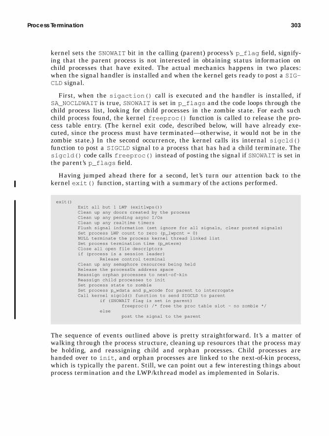
Process Termination 303
kernel sets the SNOWAITbit in the calling (parent) process’s p_flag field, signify-ing that the parent process is not interested in obtaining status information onchild processes that have exited. The actual mechanics happens in two places:when the signal handler is installed and when the kernel gets ready to post a SIG-CLD signal.
First, when the sigaction() call is executed and the handler is installed, ifSA_NOCLDWAITis true, SNOWAITis set in p_flags and the code loops through thechild process list, looking for child processes in the zombie state. For each suchchild process found, the kernel freeproc() function is called to release the pro-cess table entry. (The kernel exit code, described below, will have already exe-cuted, since the process must have terminated—otherwise, it would not be in thezombie state.) In the second occurrence, the kernel calls its internal sigcld()function to post a SIGCLD signal to a process that has had a child terminate. Thesigcld() code calls freeproc() instead of posting the signal if SNOWAITis set inthe parent’s p_flags field.
Having jumped ahead there for a second, let’s turn our attention back to thekernel exit() function, starting with a summary of the actions performed.
The sequence of events outlined above is pretty straightforward. It’s a matter ofwalking through the process structure, cleaning up resources that the process maybe holding, and reassigning child and orphan processes. Child processes arehanded over to init , and orphan processes are linked to the next-of-kin process,which is typically the parent. Still, we can point out a few interesting things aboutprocess termination and the LWP/kthread model as implemented in Solaris.
exit() Exit all but 1 LWP (exitlwps()) Clean up any doors created by the process Clean up any pending async I/Os Clean up any realtime timers Flush signal information (set ignore for all signals, clear posted signals) Set process LWP count to zero (p_lwpcnt = 0) NULL terminate the process kernel thread linked list Set process termination time (p_mterm) Close all open file descriptors if (process is a session leader) Release control terminal Clean up any semaphore resources being held Release the processUs address space Reassign orphan processes to next-of-kin Reassign child processes to init Set process state to zombie Set process p_wdata and p_wcode for parent to interrogate Call kernel sigcld() function to send SIGCLD to parent if (SNOWAIT flag is set in parent) freeproc() /* free the proc table slot - no zombie */ else post the signal to the parent

304 The Solaris Multithreaded Process Architecture
8.5.1 The LWP/kthread Model
The exitlwps() code is called immediately upon entry to the kernel exit()function, which, as the name implies, is responsible for terminating all but oneLWP in the process. If the number of LWPs in the process is 1 (the p_lwpcnt fieldin the proc structure) and there are no zombie LWPs (p_zombcnt is 0), thenexitlwps() will simply turn off the SIGWAITING signal and return. SIGWAIT-ING is used to create more LWPs in the process if runnable user threads are wait-ing for a resource. We certainly do not want to catch SIGWAITING signals andcreate LWPs when we’re terminating.
If the process has more than one LWP, the LWPs must be stopped (quiesced) sothey are not actively changing state or attempting to grab resources (file opens,stack/address space growth, etc.). Essentially what happens is this:
1. The kernel loops through the list of LWP/kthreads in the process, setting thet_astflag in the kernel thread. If the LWP/kthread is running on a proces-sor, the processor is forced to enter the kernel through the cross-call inter-rupt mechanism.
2. Inside the trap handler, which is entered as a result of the cross-call, the ker-nel tests the t_astflag (which is set) and tests for what condition it is thatrequires post-trap processing. The t_astflag specifically instructs the ker-nel that some additional processing is required following a trap.
3. The trap handler tests the process HOLDFORK flag and if it is set in p_flags(which it will be in this case), calls a holdlwp() function that, under differ-ent circumstances, would suspend the LWP/kthread.
4. During an exit, with EXITLWPS set in p_flags , the lwp_exit() functionis called to terminate the LWP. If the LWP/kthread is in a sleep or stoppedstate, then it is set to run so it can ultimately be quiecsed as described.
The kernel lwp_exit() function does per-LWP/kthread cleanup, such as timers,doors, signals, and scheduler activations. Finally, the LWP/kthread is placed on theprocess’s linked list of zombie LWPs, p_zomblist . Once all but one of theLWP/kthreads in the process have been terminated and placed on the process zom-bie list, the exit() code moves on to execute the functions summarized on theprevious page.

Process Termination 305
The pseudocode below summarizes the exitlwps() function.
Once the exit() code has completed, the process is in a zombie state, occupyingonly a process table entry and PID structure. When a wait() call is issued on thezombie, the kernel freeproc() function is called to free the process and PIDstructures.
8.5.2 Deathrow
exitlwps() does one last bit of work before it returns to exit() . It places a zom-bie’s kernel threads on deathrow.
The kernel maintains a list, called deathrow, of LWPs and kernel threads thathave exited, in order to reap a terminated LWP/kthread when a new one needs tobe created (fork() ). If an LWP/kthread is available on the list of zombies, the ker-nel does not need to allocate the data structures and stack for a new kthread; itsimply uses the structures and stack from the zombie kthread and links thekthread to the process that issued the fork (2) (or thread_create() ).
In the process creation flow, when the forklwp() code calls lwp_create() ,lwp_create() first looks on deathrow for a zombie thread. If one exists, the LWP,kthread, and stack are linked to the process, and the kernel is spared the need toallocate new kthread, LWP, and stack space during the fork() process. The ker-nel simply grabs the structures from the deathrow list, links the pointers appropri-ately, and moves on. thread_create() (kernel thread create, not the user threadAPI), called from lwp_create() , is passed the LWP data and stack and thusavoids doing any kernel memory allocations.
A kernel thread, thread_reaper() , runs periodically and cleans up zombiethreads that are sitting on deathrow. The list of zombie threads on deathrow is notallowed to grow without bounds (no more than 32 zombies), and the zombies arenot left on deathrow forever.
exitlwps() if (process LWP count == 1) nuke SIGWAITING return else for (each LWP/kthread on the process linked list) if (LWP/kthread is sleeping or stopped) make it runnable if (LWP/kthread is running on a processor) t_astflag = 1; poke_cpu() /* cross-call, to trap into the kernel */ holdlwp() lwp_exit() place kthread/LWP on zombie list done (loop) place zombie threads on deathrow return to kernel exit()
306 The Solaris Multithreaded Process Architecture
8.6 Procfs — The Process File System
The process file system, procfs, is a pseudo file system. Pseudo file systems pro-vide file-like abstractions and file I/O interfaces to something that is not a file inthe traditional sense. Procfs abstracts the Solaris kernel’s process architecturesuch that all processes running on the system appear in the root directory namespace under the /proc directory; every process in the system exists as a file under/proc , with the process’s PID serving as the file name. The PID file name under/proc is actually a directory, containing other files and subdirectories that, com-bined, make up the complete /proc directory space. The many kernel data struc-tures that provide process data and control points appear as files within the/proc/<PID> directory hierarchy, and multithreaded processes have a subdirec-tory for each LWP in the process. Per-LWP data and control structures exist asfiles under the /proc/<PID>/lwp/<LWP_ID> . The objects that appear under/proc are not on-disk files; they are objects that exist in kernel memory. When auser executes an ls (1) command in /proc or any /proc subdirectory, the systemis reading kernel memory.
This file-like abstraction for processes provides a simple and elegant means ofextracting information about processes, their execution environment, and kernelresource utilization. Simple things, such as opening a /proc file object to read bitsof information about a process, are relatively easy to do with procfs. Process con-trol is powerful and relatively straightforward; processes can be stopped andstarted, and event-driven stops can be established for things like signals, traps,and system calls. In general, process management and debugging is greatly simpli-fied. It is worth noting that the original design goal of procfs was to provide a set ofinterfaces for writing debuggers; it has evolved considerably since the originalimplementation.
The Solaris system ships with several commands that implement /proc forextracting information and issuing control directives. These commands reside inthe /usr/proc/bin directory and are described in the proc (1) manual page. Weuse some of these commands throughout the book to provide examples of differentkernel abstractions, such as opened files or a process’s address space. The processstatus command, ps (1), is also built on top of the procfs interfaces.
The control and informational data made available through the /proc file sys-tem is maintained in a hierarchy of files and subdirectories. The files and subdirec-tories implemented in /proc are listed below. See the proc (4) manual page foradditional information on these files and their use.
• /proc — The top-level directory for procfs.
• / proc/<pid> — The top-level directory for a specific process, where the pro-cess’s PID is the directory name.

Procfs — The Process File System 307
• /proc/<pid>/as — The process’s address space, as defined by the p_as linkto an address space structure (struct as ) in the process’s proc structure. Inother words, the process’s address space as represented by the/proc/<pid>/as file is not a /proc -specific representation of the addressspace. Rather, /proc provides a path to address space mappings through theproc structure’s p_as pointer.
• /proc/<pid>/ctl — A process control file. Can be opened for write-only,and can be used to send control messages to a process to initiate a specificevent or to enable a particular behaviour. Examples include stopping or start-ing a process, setting stops on specific events, or turning on microstateaccounting.This file exemplifies the power and elegance of procfs; you can accomplishprocess control and event tracing by opening the control file for the targetprocess and writing a control message (or multiple control messages) to injectdesired behavior. See the proc (4) man page for a detailed list of control mes-sages and functions.
• /proc/<pid>/status — General state and status information about theprocess. The specific contents are defined in the pstatus structure, definedin /usr/include/sys/procfs.h . pstatus is also described in proc (4).Note that pstatus embeds an lwpstatus structure (the pr_lwp field ofpstatus ). This structure is described as a representative LWP. A non-threaded process has only one LWP, so selecting a representative LWP is sim-ple. For threaded processes with multiple LWPs, an internal kernel routineloops through all the LWPs in the process and selects one on the basis of itsstate. First choice is an executing LWP. If an executing LWP is not available,selection criteria look for runnable, sleeping, or stopped.
• /proc/<pid>/lstatus — An array of lwpstatus structures, one for eachLWP in the process.
• /proc/<pid>/psinfo — Process information as provided by the ps (1) com-mand. Similar to the status data as described above, in that a representativeLWP is included with an embedded lwpsinfo structure.
• /proc/<pid>/lpsinfo — Per-LWP ps (1) information.
• /proc/<pid>/map — Address space map information. The data displayed bythe pmap(1) command.
• /proc/<pid>/rmap — Reserved address space segments of the process.
• /proc/<pid>/xmap — Extended address space map information. The datadisplayed when the pmap(1) command is run with the -x flag.
• /proc/<pid>/cred — Process credentials, as described in the prcredstructure (/usr/include/sys/procfs.h ).

308 The Solaris Multithreaded Process Architecture
• /proc/<pid>/sigact — Array of sigaction structures, each representingthe signal disposition for all signals associated with the process.
• /proc/<pid>/auxv — An array of auxv (auxiliary vector, defined in/usr/include/sys/auxv.h ) structures, with the initial values as passed tothe dynamic linker when the process was exec’d.
• /proc/<pid>/ldt — Local descriptor table. Intel x86 architecture only.
• /proc/<pid>/usage — Process resource usage data. See “Process ResourceUsage” on page 318.
• /proc/<pid>/lusage — Array of LWP resource usage data. See “ProcessResource Usage” on page 318.
• /proc/<pid>/pagedata — Another representation of the process’s addressspace. Provides page-level reference and modification tracking.
• /proc/<pid>/watch — An array of prwatch structures (defined in/usr/include/sys/procfs.h ), as created when the kernel sets a PCWATCHoperation by writing to the control file. Allows for monitoring (watching) oneor more address space ranges, such that a trap is generated when a memoryreference is made to a watched page.
• /proc/<pid>/cwd — Symbolic link to the process’s current working direc-tory.
• /proc/<pid>/root — Symbolic link to the process’s root directory.
• /proc/<pid>/fd — Directory that contains references to the process’s openfiles.
• /proc/<pid>/fd/nn — The process’s open file descriptors. Directory filesare represented as symbolic links.
• /proc/<pid>/object — Subdirectory containing binary shared object filesthe process is linked to.
• /proc/<pid>/object/nn — Binary object files. The process’s executablebinary (a.out ), along with shared object files the process is linked to.
In addition to the file objects and subdirectories maintained at the process level,each /proc/<pid>/ directory has an lwp subdirectory, which contains several fileobjects that contain per-LWP data. Subdirectories are described below.
• /proc/<pid>/lwp — Subdirectory containing files that represent all theLWPs in the process.
• /proc/<pid>/lwp/<lwpid> — Subdirectory containing the procfs files spe-cific to an LWP.
• /proc/<pid>/lwp/<lwpid>/lwpctl — Control file for issuing control oper-ations on a per-LWP basis.

Procfs — The Process File System 309
• /proc/<pid>/lwp/<lwpid>/lwpstatus — LWP state and status informa-tion, as defined in the lwpstatus structure in/usr/include/sys/procfs.h .
• /proc/<pid>/lwp/<lwpid>/lwpsinfo — LWP ps (1) command informa-tion, as defined in lwpsinfo , also in /usr/include/sys/procfs.h .
• /proc/<pid>/lwp/<lwpid>/lwpusage — LWP resource usage data. See“Process Resource Usage” on page 318.
• /proc/<pid>/lwp/<lwpid>/xregs — Extra general state registers — Thisfile is processor-architecture specific and may not be present on some plat-forms. On SPARC-based systems, the data contained in this file is defined inthe prxregset structure, in /usr/include/sys/procfs_isa.h .
• /proc/<pid>/lwp/<lwpid>/gwindow s — General register windows. Thisfile exists on SPARC-based systems only and represents the general registerset of the LWP (part of the hardware context), as defined in the gwindowsstructure in /usr/include/sys/regset.h .
• /proc/<pid>/lwp/<lwpid>/asrs — Ancillary register set. SPARC V9architecture (UltraSPARC) only. An additional set of hardware registersdefined by the SPARC V9 architecture. This file, representing the ancillaryregisters, is present only on sun4u based systems running a 64-bit kernel(Solaris 7 or later), and only for 64-bit processes. (Remember, a 64-bit kernelcan run 32-bit processes. A 32-bit process will not have this file in its lwp sub-directory space.)
That completes the listing of files and subdirectories in the procfs directory space.Once again, please refer to the proc (4) manual page for more detailed informa-tion on the various files in /proc and for a complete description of the control mes-sages available.
8.6.1 Procfs Implementation
Procfs is implemented as a dynamically loadable kernel module, /ker-nel/fs/procfs , and is loaded automatically by the system at boot time. /proc ismounted during system startup by virtue of the default /proc entry in the/etc/vfstab file. The mount phase causes the invocation of the procfs prinit()(initialize) and prmount() file-system-specific functions, which initialize the vfsstructure for procfs and create and initialize a vnode for the top-level directoryfile, /proc .
The kernel memory space for the /proc files is, for the most part, allocateddynamically, with an initial static allocation for the number of directory slotsrequired to support the maximum number of processes the system is configured tosupport (see “The Kernel Process Table” on page 290).

310 The Solaris Multithreaded Process Architecture
A kernel procdir (procfs directory) pointer is initialized as a pointer to anarray of procent (procfs directory entry) structures. The size of this array isderived from the v.v_proc variable established at boot time, representing themaximum number of processes the system can support. The entry in procdirmaintains a pointer to the process structure and maintains a link to the next entryin the array. The procdir array is indexed through the pr_slot field in the pro-cess’s pid structure. The procdir slot is allocated to the process from the arrayand initialized at process creation time (fork() ), as shown in Figure 8.16.
Figure 8.16 procfs Kernel Process Directory Entries
The specific format of the procfs directory entries is described in the procfs kernelcode. It is modeled after a typical on-disk file system: each directory entry in thekernel is described with a directory name, offset into the directory, a length field,and an inode number. The inode number for a /proc file object is derived inter-nally from the file object type and process PID. Note that /proc directory entriesare not cached in the directory name lookup cache (dnlc); by definition they arealready in physical memory.
Because procfs is a file system, it is built on the Virtual File System (VFS) andvnode framework. In Solaris, an instance of a file system is described by a vfsobject, and the underlying files are each described by a vnode . The vfs/vnodearchitecture is described in “Solaris File System Framework” on page 541. Procfsbuilds the vfs and vnode structures, which are used to reference the file-sys-tem-specific functions for operations on the file systems (e.g., mount, unmount),and file system specific functions on the /proc directories and file objects (e.g.,open, read, write).
Beyond the vfs and vnode structures, the procfs implementation defines twoprimary data structures used to describe file objects in the /proc file system. Thefirst, prnode , is the file-system-specific data linked to the vnode . Just as the ker-nel UFS implementation defines an inode as a file-system-specific structure thatdescribes a UFS file, procfs defines a prnode to describe a procfs file. Every file inthe /proc directory has a vnode and prnode . A second structure, prcommon,exists at the directory level for /proc directory files. That is, the /proc/<pid>and /proc/<pid>/lwp/<lwpid> directories each have a link to a prcommon
pe_procpe_next
pe_procpe_next
pe_procpe_next
0
v.v_proc
procdirproc
p_pidp pid_prslotpid_id
The process’s PID structurepid_prslot pointer indexesthe procdir array.
proc
p_pidp
proc
p_pidp
kern
el p
roce
ss ta
ble
pid_prslotpid_id
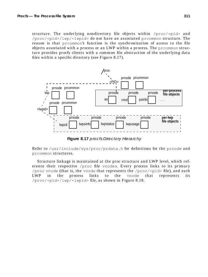
Procfs — The Process File System 311
structure. The underlying nondirectory file objects within /proc/<pid> and/proc/<pid>/lwp/<lwpid> do not have an associated prcommon structure. Thereason is that prcommon ’s function is the synchronization of access to the fileobjects associated with a process or an LWP within a process. The prcommon struc-ture provides procfs clients with a common file abstraction of the underlying datafiles within a specific directory (see Figure 8.17).
Figure 8.17 procfs Directory Hierarchy
Refer to /usr/include/sys/proc/prdata.h for definitions for the prnode andprcommon structures.
Structure linkage is maintained at the proc structure and LWP level, which ref-erence their respective /proc file vnodes . Every process links to its primary/proc vnode (that is, the vnode that represents the /proc/<pid> file), and eachLWP in the process links to the vnode that represents its/proc/<pid>/lwp/<lwpid> file, as shown in Figure 8.18.
proc
<PID>prcommon
lwpprnode prcommon
as
prnode prnode
prnode
cred psinfo . . .
prnodeper-processfile objects
<lwpid>
prnode prcommon
lwpctl
prnode prnode prnode prnode
lwpsinfo lwpstatus lwpusage
per-lwpfile objects

312 The Solaris Multithreaded Process Architecture
Figure 8.18 procfs Data Structures
Figure 8.18 provides a partial view of what the procfs data structures and relatedlinks look like when a procfs file is opened for reading or writing. Note that all ofthe vnodes associated with a process are linked through the pr_next pointer inthe prnode . When a reference is made to a procfs directory and underlying fileobject, the kernel dynamically creates the necessary structures to service a clientrequest for file I/O. More succinctly, the procfs structures and links are created andtorn down dynamically. They are not created when the process is created (asidefrom the procdir procfs directory entry and directory slot allocation). Theyappear to be always present because the files are available whenever an open (2)request is made or a lookup is done on a procfs directory or data file object. (It issomething like the light in your refrigerator—it’s always on when you look, but notwhen the door is closed.)
The data made available through procfs is, of course, always present in the ker-nel proc structures and other data structures that, combined, form the completeprocess model in the Solaris kernel. This model, shown in Figure 8.5 on page 270,represents the true source of the data extracted and exported by procfs. By hidingthe low-level details of the kernel process model and abstracting the interestinginformation and control channels in a relatively generic way, procfs provides a ser-
procstructure
kthread LWP
kthread LWP
A m
ultit
hrea
ded
proc
ess
p_trace
p_plist
t_trace
t_trace
vnodestructure
prnode
v_data
pr_common
prcommonpr_next
pr_v
node
/proc/<PID>vnode
vnodestructure
prnode
v_data
pr_common
prcommonpr_next
pr_v
node
/proc/<PID>/lwp/<LWPID>vnode
vnodestructure
prnode
v_data
pr_common
prcommonpr_next
pr_v
node
/proc/<PID>/lwp/<LWPID>vnode
pe_procpe_next
pe_procpe_next
pe_procpe_next
procdir
prc_slot
pointsback tothe procstructurepr_files
pr_files
pr_files
array ofpointersto vnodesfor all fileswithin thedirectory

Procfs — The Process File System 313
vice to client programs interested in extracting bits of data about a process orsomehow controlling the execution flow. The abstractions are created whenrequested and are maintained as long as necessary to support file access andmanipulation requests for a particular file.
File I/O operations through procfs follow the conventional methods of first open-ing a file to obtain a file descriptor, then performing subsequent read/write opera-tions and closing the file when completed. The creation and initialization of theprnode and prcommon structures occur when the procfs-specific vnode opera-tions are entered through the vnode switch table mechanism as a result of a cli-ent (application program) request. The actual procfs vnode operations havespecific functions for the lookup and read operations on the directory and data fileswithin the /proc directory.
The implementation in procfs of lookup and read requests through an array offunction pointers that resolve to the procfs file-type-specific routine is accom-plished through the use of a lookup table and corresponding lookup functions. Thefile type is maintained at two levels. At the vnode level, procfs files are defined asVPROCfile types (v_type field in the vnode ). The prnode includes a type field(pr_type ) that defines the specific procfs file type being described by the pnode.The procfs file types correspond directly to the description of /proc files and direc-tories that are listed at the beginning of this section (“Procfs — The Process FileSystem” on page 306). Examples include the various directory types (a process PIDdirectory, an LWPID directory, etc.) and data files (status, psinfo, address space,etc.).
The basic execution flow of a procfs file open is shown in Figure 8.19.
Figure 8.19 procfs File Open
The function flow in Figure 8.19 starts at the application program level, where anopen (2) system call is issued on a procfs file. The vnode kernel layer is entered
open("/proc/<PID>/<dataf i le>",O_RDONLY);
vn_open()
lookupxxx()VOP_LOOKUP() -> prlookup()
pr_lookup_functionpr_lookup_piddir()
pr_lookup_lwpdir()
pr_lookup_objectdir()
index based on type
prgetnode ()Construct full path name,looking up each elementin the path.
VOP_OPEN() -> propen()
Specific procfs directory objectlookup functions are invokedthrough the pr_lookup_function[]array.
code
flow

314 The Solaris Multithreaded Process Architecture
(vn_open() ), and a series of lookups is performed to construct the full path nameof the desired /proc file. Macros in the vnode layer invoke file-system-specificoperations. In this example, VOP_LOOKUP() will resolve to the procfspr_lookup() function. pr_lookup() will do an access permissions check andvector to the appropriate procfs function based on the directory file type, for exam-ple, pr_lookup_piddir() to perform a lookup on a /proc/<PID> directory. Eachof the pr_lookup_xxx() directory lookup functions does some directory-type-spe-cific work and calls prgetnode() to fetch the prnode .
prgetnode() creates the prnode (which includes the embedded vnode ) for the/proc file and initializes several of the prnode and vnode fields. For /proc PIDand LWPID directories (/proc/<PID> , /proc/<PID>/lwp/<LWPID> ), theprcommon structure is created, linked to the prnode, and partially initialized. Notethat for /proc directory files, the vnode type will be changed from VPROC(set ini-tially) to VDIR, to correctly reflect the file type as a directory (it is a procfs direc-tory, but a directory file nonetheless).
Once the path name is fully constructed, the VOP_OPEN() macro invokes thefile-system-specific open() function. The procfs propen() code does some addi-tional prnode and vnode field initialization and file access testing for specific filetypes. Once propen() completes, control is returned to vn_open() and ulti-mately a file descriptor representing a procfs file is returned to the caller.
The reading of a procfs data file object is similar in flow to the open scenario,where the execution of a read system call on a procfs file will ultimately cause thecode to enter the procfs prread() function. The procfs implementation defines adata-file-object-specific read function for each of the file objects (data structures)available: pr_read_psinfo() , pr_read_pstatus() , pr_read_lwpsinfo() ,etc. The specific function is entered from prread() through an array of functionpointers indexed by the file type—the same method employed for the previouslydescribed lookup operations.
The Solaris 7 implementation of procfs, where both 32-bit and 64-bit binary exe-cutables can run on a 64-bit kernel, provides 32-bit versions of the data files avail-able in the /proc hierarchy. For each data structure that describes the contents ofa /proc file object, a 32-bit equivalent is available in a 64-bit Solaris 7 kernel (e.g.,lwpstatus and lwpstatus32 , psinfo and psinfo32 ). In addition to the 32-bitstructure definitions, each of the pr_read_ xxx () functions has a 32-bit equiva-lent in the procfs kernel module, more precisely, a function that deals specificallywith the 32-bit data model of the calling program. Procfs users are not exposed tothe multiple data model implementation in the 64-bit kernel. When prread() isentered, it checks the data model of the calling program and invokes the correctfunction as required by the data model of the caller. An exception to this is a readof the address space (/proc/<PID>/as ) file; the caller must be the same datamodel. A 32-bit binary cannot read the as file of a 64-bit process. A 32-bit processcan read the as file of another 32-bit process running on a 64-bit kernel.
The pr_read_ xxxx () functions essentially read the data from its originalsource in the kernel and write it to the corresponding procfs data structure fields,
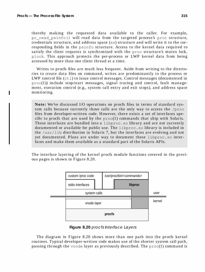
Procfs — The Process File System 315
thereby making the requested data available to the caller. For example,pr_read_psinfo() will read data from the targeted process’s proc structure,credentials structure, and address space (as ) structure and will write it to the cor-responding fields in the psinfo structure. Access to the kernel data required tosatisfy the client requests is synchronized with the proc structure’s mutex lock,plock . This approach protects the per-process or LWP kernel data from beingaccessed by more than one client thread at a time.
Writes to procfs files are much less frequent. Aside from writing to the directo-ries to create data files on command, writes are predominantly to the process orLWP control file (ctl ) to issue control messages. Control messages (documented inproc (1)) include stop/start messages, signal tracing and control, fault manage-ment, execution control (e.g., system call entry and exit stops), and address spacemonitoring.
The interface layering of the kernel procfs module functions covered in the previ-ous pages is shown in Figure 8.20.
Figure 8.20 procfs Interface Layers
The diagram in Figure 8.20 shows more than one path into the procfs kernelroutines. Typical developer-written code makes use of the shorter system call path,passing through the vnode layer as previously described. The proc (1) command is
Note: We’ve discussed I/O operations on procfs files in terms of standard sys-tem calls because currently those calls are the only way to access the /procfiles from developer-written code. However, there exists a set of interfaces spe-cific to procfs that are used by the proc (1) commands that ship with Solaris.These interfaces are bundled into a libproc.so library and are not currentlydocumented or available for public use. The libproc.so library is included inthe /usr/lib distribution in Solaris 7, but the interfaces are evolving and notyet documented. Plans are under way to document these libproc.so inter-faces and make them available as a standard part of the Solaris APIs.
stdio interfaces
system calls
vnode layer
libproc
procfs
user
kernel
/usr/proc/bin/<commands>custom /proc code
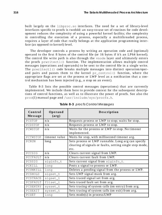
316 The Solaris Multithreaded Process Architecture
built largely on the libproc.so interfaces. The need for a set of library-levelinterfaces specific to procfs is twofold: an easy-to-use set of routines for code devel-opment reduces the complexity of using a powerful kernel facility; the complexityin controlling the execution of a process, especially a multithreaded process,requires a layer of code that really belongs at the application programming inter-face (as opposed to kernel) level.
The developer controls a process by writing an operation code and (optional)operand to the first 8 bytes of the control file (or 16 bytes if it’s an LP64 kernel).The control file write path is also through the vnode layer and ultimately entersthe procfs prwritectl() function. The implementation allows multiple controlmessages (operations and operands) to be sent to the control file in a single write.The prwritectl() code breaks multiple messages into distinct operation/oper-and pairs and passes them to the kernel pr_control() function, where theappropriate flags are set at the process or LWP level as a notification that a con-trol mechanism has been injected (e.g., a stop on an event).
Table 8-3 lists the possible control messages (operations) that are currentlyimplemented. We include them here to provide context for the subsequent descrip-tions of control functions, as well as to illustrate the power of procfs. See also theproc (1) manual page and /usr/include/sys/procfs.h .
Table 8-3 procfs Control Messages
ControlMessage
Operand(arg)
Description
PCSTOP n/a Requests process or LWP to stop; waits for stop.PCDSTOP n/a Requests process or LWP to stop.PCWSTOP n/a Waits for the process or LWP to stop. No timeout
implemented.PCTWSTOP timeout value Waits for stop, with millisecond timeout arg.PCRUN long Sets process or LWP runnable. Long arg can specify
clearing of signals or faults, setting single step mode,etc.
PCCSIG n/a Clears current signal from LWP.PCCFAULT n/a Clears current fault from LWP.PCSSIG siginfo_t Sets current signal from siginfo_t .PCKILL long Posts a signal to process or LWP.PCUNKILL long Deletes a pending signal from the process or LWP.PCSHOLD sigset_t Sets LWP signal mask from arg.PCSTRACE sigset_t Sets traced signal set from arg.PCSFAULT fltset_t Sets traced fault set from arg.PCSENTRY sysset_t Sets tracing of system calls (on entry) from arg.PCSEXIT sysset_t Sets tracing of system calls (on exit) from arg.PCSET long Sets mode(s) in process/LWP

Procfs — The Process File System 317
As you can see from the variety of control messages provided, the implementationof process/LWP control is tightly integrated with the kernel process/LWP sub-system. Various fields in the process, user (uarea ), LWP, and kernel thread struc-tures facilitate process management and control with procfs. Establishing processcontrol involves setting flags and bit mask fields to track events that cause a pro-cess or thread to enter or exit the kernel. These events are signals, system calls,and fault conditions. The entry and exit points for these events are well definedand thus provide a natural inflection point for control mechanisms.
The system call, signals, and faults are set through the use of a set data type,where sigset_t , sysset_t , and fltset_t operands have values set by the call-ing (controlling) program to specify the signal, system call, or fault condition ofinterest. A stop on a system call entry occurs when the kernel is first entered (thesystem call trap), before the argument list for the system call is read from the pro-cess. System call exit stops have the process stop after the return value from thesystem call has been saved. Fault stops also occur when the kernel is first entered;fault conditions generate traps, which force the code into a kernel trap handler.Signal stops are tested for at all the points where a signal is detected, on a returnfrom a system call or trap, and on a wakeup (see “Signals” on page 324).
Address space watch directives allow a controlling process to specify a virtualaddress, range (in bytes), and access type (e.g., read or write access) for a segmentof a process’s virtual address space. When a watched event occurs, a watchpointtrap is generated, which typically causes the process or LWP to stop, eitherthrough a trace of a FLTWATCH fault or by an unblocked SIGTRAP signal.
In some cases, the extraction of process information and process control requiresthe controlling process to have the target process perform specific instructions on
PCUNSET long Unsets mode(s) in process/LWPPCSREG prgregset_t Sets LWP’s general registers from arg.PCSFPREG prfpregset_
tSets LWP’s floating-point registers from arg.
PCSXREG prxregset_t Sets LWP’s extra registers from arg.PCNICE long Sets nice value from arg.PCSVADDR long Sets PC (program counter) to virtual address in arg.PCWATCH prwatch_t Sets or clears watched memory area from arg.PCAGENT prgregset_t Creates agent LWP with register values from arg.PCREAD priovec_t Reads from the process address space through arg.PCWRITE priovec_t Writes to process address space through arg.PCSCRED prcred_t Sets process credentials from arg.PCSASRS asrset_t Sets ancillary state registers from arg.
Table 8-3 procfs Control Messages (Continued)
ControlMessage
Operand(arg)
Description

318 The Solaris Multithreaded Process Architecture
its behalf. For example, the pfiles (1) command, which lists the open files of aprocess and provides information about each opened file, requires the target pro-cess to issue a stat (2) system call on each of its open file descriptors. Since thetypical process running on a Solaris system spends a fair amount of its time block-ing on a system call (not related to procfs), getting control of the target process toperform a specific task requires grabbing the process while it is blocked and pre-serving the system call state, so it can be restored and resume properly when thecontrolling process has had its request satisfied.
Procfs implements an agent LWP for this purpose. Rather than complicatingstate preservation and restoration by using an existing LWP in the target process,procfs provides a facility for creating an agent LWP (note the PCAGENTcontrolmessage). When an agent LWP is created, it remains the only runnable LWP in theprocess for the duration of its existence. The agent LWP controls the execution ofthe target process as required to satisfy the controlling process’s request (e.g., exe-cutes system calls within the target process). When completed, the agent LWP isdestroyed and the process/LWP state is restored. The proc structure maintains apointer, p_agenttp , that is linked to the agent LWP when one is created. A test onthis pointer in various areas of the kernel determines whether an agent LWPexists for the process.
The finer details of the process control directives, how to use them, and the sub-tleties of the behavior they create are well documented in the proc (4) manualpage.
Among its many benefits, procfs enables us to track and extract informationabout process resource utilization and state changes—the subject of the next sec-tion.
8.6.2 Process Resource Usage
The kernel supports the gathering of relatively fine-grained resource-utilizationinformation in the process framework. Resource usage data is a collection ofcounters, embedded in a structure called lrusage . Both the process and LWP con-tain an lrusage structure. Data is collected (the counters incremented) duringLWP execution. When an LWP terminates, the lrusage data is copied from theLWP to the process-level lrusage structure. Thus, the data reflected at the pro-cess level represents the sum total for all the LWPs in the process. Table 8-4describes the lrusage counters.
Table 8-4 lrusage Fields
Field Descriptionminflt Minor page faults (a page fault resolved without a disk I/O).majflt Major page faults (disk I/O required). Incremented in the ker-
nel block I/O pageio_setup() routine, which sets up a bufstruct for a page.

Procfs — The Process File System 319
The resource utilization counters do not require enabling microstate accounting forthe process or LWP. They are accessible through the usage structure maintainedby procfs, where /proc/<PID>/usage represents the process level usage and/proc/<PID>/lwp/<LWP_ID>/lwpusage represents the per-LWP usage data.See the source code in Appendix C, “A Sample Procfs utility”.
Within the process, the operating system maintains a high-resolution time-stamp that marks process start and terminate times. A p_mstart field, the pro-cess start time, is set in the kernel fork() code when the process is created, andthe process termination time, p_mterm , is set in the kernel exit() code. Start andtermination times are also maintained in the LWP when microstate accounting isenabled. The associated process’s p_mlreal field contains a sum of the LWP’selapsed time, as derived from the start and terminate times.
The system uses an internal gethrtime() routine,get_high_resolution_time (there is an equivalent gethrtime (3C) API).When get_high_resolution_time is called, it returns a 64-bit value expressedin nanoseconds. The value is not related to current time and thus is only usefulwhen used in conjunction with a subsequent call to gethrtime() . In that case,
nswap Number of times the LWP was swapped out. Incremented inthe LWP swapout() code.
inblock Number of input blocks. Incremented in the kernel block I/Osubsystem (bio.c ) for block device reads.
outblock Number of output blocks. As above, incremented in bio.c forblock device writes.
msgsnd STREAMS messages sent. Incremented in the STREAMScommon code for putmsg() .
msgrcv STREAMS messages received. Incremented in the STREAMScommon code for getmsg() .
nsignals Number of signals received. Incremented in the kernelpsig() code, where the LWP is set up to run the signal han-dler.
nvcsw Number of voluntary context switches. Incremented when anLWP blocks (is put to sleep), waiting for an I/O or synchroniza-tion primitive.
nivcsw Number of involuntary context switches. Incremented whenan LWP is context-switched because it uses up its alloted timequantum or is preempted by a higher-priority kthread.
sysc Number of system calls. Incremented in the system call traphandler.
ioch Characters read and written. Incremented in the read/writesystem call code.
Table 8-4 lrusage Fields (Continued)
Field Description
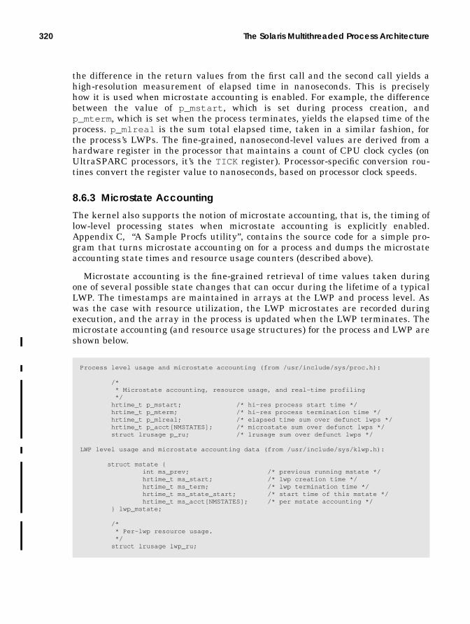
320 The Solaris Multithreaded Process Architecture
the difference in the return values from the first call and the second call yields ahigh-resolution measurement of elapsed time in nanoseconds. This is preciselyhow it is used when microstate accounting is enabled. For example, the differencebetween the value of p_mstart , which is set during process creation, andp_mterm , which is set when the process terminates, yields the elapsed time of theprocess. p_mlreal is the sum total elapsed time, taken in a similar fashion, forthe process’s LWPs. The fine-grained, nanosecond-level values are derived from ahardware register in the processor that maintains a count of CPU clock cycles (onUltraSPARC processors, it’s the TICK register). Processor-specific conversion rou-tines convert the register value to nanoseconds, based on processor clock speeds.
8.6.3 Microstate Accounting
The kernel also supports the notion of microstate accounting, that is, the timing oflow-level processing states when microstate accounting is explicitly enabled.Appendix C, “A Sample Procfs utility”, contains the source code for a simple pro-gram that turns microstate accounting on for a process and dumps the microstateaccounting state times and resource usage counters (described above).
Microstate accounting is the fine-grained retrieval of time values taken duringone of several possible state changes that can occur during the lifetime of a typicalLWP. The timestamps are maintained in arrays at the LWP and process level. Aswas the case with resource utilization, the LWP microstates are recorded duringexecution, and the array in the process is updated when the LWP terminates. Themicrostate accounting (and resource usage structures) for the process and LWP areshown below.
Process level usage and microstate accounting (from /usr/include/sys/proc.h):
/* * Microstate accounting, resource usage, and real-time profiling */ hrtime_t p_mstart; /* hi-res process start time */ hrtime_t p_mterm; /* hi-res process termination time */ hrtime_t p_mlreal; /* elapsed time sum over defunct lwps */ hrtime_t p_acct[NMSTATES]; /* microstate sum over defunct lwps */ struct lrusage p_ru; /* lrusage sum over defunct lwps */
LWP level usage and microstate accounting data (from /usr/include/sys/klwp.h):
struct mstate { int ms_prev; /* previous running mstate */ hrtime_t ms_start; /* lwp creation time */ hrtime_t ms_term; /* lwp termination time */ hrtime_t ms_state_start; /* start time of this mstate */ hrtime_t ms_acct[NMSTATES]; /* per mstate accounting */ } lwp_mstate;
/* * Per-lwp resource usage. */ struct lrusage lwp_ru;

Procfs — The Process File System 321
By default, microstate accounting is disabled to keep overhead down to a mini-mum. Turning microstate accounting on must be done programmatically by meansof /proc . The process control file, /proc/<pid>/ctl , must be opened and a con-trol message sent in the form of a write (2) to the control file, which requires anoperator (PCSET) and an operand (PR_MSACCT). Here is a partial code example ofhow to enable microstate accounting in a process.
Once microstate accounting is enabled, it is reflected in a flag at the process level(SMSACCTin the proc structure’s p_flag field) and at the LWP/kthread level(TP_MSACCTin the t_proc_flag field). The kernel lwp_create() code tests theprocess level SMSACCTflag to determine if microstate accounting has been enabled.If it has, then lwp_create() sets the TP_MSACCTflag in the kernel thread. Alsolwp_create() initializes the microstate accounting structure, lwp_mstate ,regardless of the state of the SMSACCTflag. This allows the kernel to set the starttime (ms_start in the LWP’s lwp_mstate structure) and initialize thems_acct[] array.
The kernel implementation of microstate accounting requires only four kernelfunctions:
• The initialization function init_mstate()
• An update function, new_mstate() , called during state changes• A function, term_mstate() , to update the process-level data when an LWP
terminates• A function, restore_mstate() , called from the dispatcher code when an
LWP/kthread has been selected for execution
At various points, the kernel code tests the TP_MSACCTflag to determine ifmicrostate accounting is enabled; if it is, the code updates the current microstateby a call into the new_mstate() function, which is passed as an argument a flagindicating the new microstate.
The microstates defined by the kernel can be found in/usr/include/sys/msacct.h . They reflect the basic execution states of anLWP/kthread: running, sleeping, or stopped. What they provide is finer-grainedinformation about a particular state, such as why an LWP/kthread was sleeping,what mode it was running in, etc. Table 8-5 describes the microstates, as main-tained in the procfs process prusage structure.
int control[2];int cfd; /* control_file_descriptor */control[0] = PCSET;control[1] = PR_MSACCT;cfd=open(“/proc/<pid>/ctl”,O_WRONLY);write(cfd, control, sizeof(control));

322 The Solaris Multithreaded Process Architecture
The microstate measurements are taken as follows. init_mstate() initializesthe microstate date of a new LWP/kthread when the LWP/kthread is created. Theinit_mstate() function performs the following actions (see the previous page).
• Set the previous microstate, ms_prev , to LMS_SYSTEM.
• Set ms_start to return value of the gethrtime() call.
• Set ms_state_start to return the value of gethrtime() call.
• Set t_mstate in the kernel thread to LMS_STOPPED.
• Set t_waitrq in the kernel thread to zero.• Zero the msacct[] array.
The LWP/kthread microstate data is thus initialized prior to executing for thefirst time. The above initialization steps show two additional microstate-relatedfields not yet discussed. In the kernel thread structure, the current microstate ismaintained in t_mstate , and t_waitrq calculates CPU wait time. We will seewhere this comes into play in a moment.
During execution if TP_MSACCTis set, calls are made to the new_mstate() rou-tine when a state transition occurs. The caller passes new_mstate() a state flag(LMS_USER, LMS_SYSTEM, etc.) that stipulates the new state. The system calcu-lates the time spent in the previous state by finding the difference between thecurrent return value of gethrtime() and the ms_state_start field, which was
Table 8-5 Microstates
prusageField
Flag Description
pr_utime LMS_USER User mode execution time.pr_stime LMS_SYSTEM System (kernel) mode execution time.pr_ttime LMS_TRAP Other system trap time (other meaning aside
from system call traps, which are accounted forin pr_stime ).
pr_tftime LMS_TFAULT Time sleeping while waiting for a page fault ona text page to be resolved.
pr_dftime LMS_DFAULT Time sleeping while waiting for a page fault ona data page to be resolved.
pr_kftime LMS_KFAULT Time sleeping while waiting for a kernel pagefault to be resolved.
pr_ltime LMS_USER_LOCK Time sleeping while waiting for a user lock(e.g., user-defined mutex lock).
pr_slptime LMS_SLEEP Any sleep time not accounted for in the abovefields.
pr_wtime LMS_WAIT_CPU Time spent waiting for an available CPU.pr_stoptime LMS_STOPPED Time spent stopped (e.g., job control or debug).
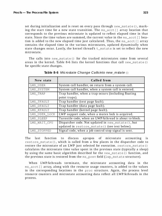
Procfs — The Process File System 323
set during initialization and is reset on every pass through new_mstate() , mark-ing the start time for a new state transition. The ms_acct[] array location thatcorresponds to the previous microstate is updated to reflect elapsed time in thatstate. Since the time values are summed, the current value in the ms_acct[] loca-tion is added to the new elapsed time just calculated. Thus, the ms_acct[] arraycontains the elapsed time in the various microstates, updated dynamically whenstate changes occur. Lastly, the kernel thread’s t_mstate is set to reflect the newmicrostate.
The calls into new_mstate() for the tracked microstates come from severalareas in the kernel. Table 8-6 lists the kernel functions that call new_mstate()for specific state changes.
The last function to discuss apropos of microstate accounting isrestore_mstate() , which is called from a few places in the dispatcher code torestore the microstate of an LWP just selected for execution. restore_mstate()calculates the microstate time value spent in the previous state (typically a sleep)by using the same basic algorithm described for the new_mstate() function, andthe previous state is restored from the ms_prev field (lwp_mstate structure).
When LWP/kthreads terminate, the microstate accounting data in thems_acct[] array, along with the resource usage counters, is added to the valuesin the corresponding locations in the proc structure. Again, the process levelresource counters and microstate accounting data reflect all LWP/kthreads in theprocess.
Table 8-6 Microstate Change Calls into new_mstate()
New state Called fromLMS_USER System call handler, on return from a system call.LMS_SYSTEM System call handler, when a system call is entered.LMS_TRAP Trap handler, when a trap occurs (including floating
point traps).LMS_TFAULT Trap handler (text page fault).LMS_DFAULT Trap handler (data page fault).LMS_KFAULT Trap handler (kernel page fault).LMS_USER_LOCK LWP support code, when a mutex lock is acquired.LMS_SLEEP Turnstile code, when an LWP/kthread is about to block.LMS_WAIT_CPU Dispatcher code. Not updated in new_mstate() , but
updated in restore_mstate() (see text below).LMS_STOPPED Signal code, when a job control stop signal is sent.

324 The Solaris Multithreaded Process Architecture
8.7 Signals
Signals are a means by which a process or thread can be notified of a particularevent. Signals are often compared with hardware interrupts, when a hardwaresubsystem, such as a disk I/O interface (e.g., a SCSI host adapter), generates aninterrupt to a processor as a result of an I/O being completed. The interrupt causesthe processor to enter an interrupt handler, so subsequent processing, based on thesource and cause of the interrupt, can be done in the operating system. The hard-ware interrupt analogy maps pretty well to what signals are all about. Similarly,when a signal is sent to a process or thread, a signal handler may be entered(depending on the current disposition of the signal), analogous to the system enter-ing an interrupt handler as the result of receiving an interrupt.
Quite a bit of history attaches to signals and design changes in the signal codeacross various implementations of Unix. These changes in the implementation andinterfaces to signals were due in part to some deficiencies in the early implementa-tion of signals, as well as the parallel development work done on different ver-sions of Unix, primarily BSD Unix and AT&T System V. This history issummarized in [25] and [10] and is not repeated here.
What does warrant mention here is that early implementations of signals weredeemed unreliable. The unreliability stemmed from the fact that, in the old days,the kernel would reset the signal handler to its default if a process caught a signaland invoked its own handler but the kernel’s reset occurred before the process’shandler was invoked. Attempts to address this issue in user code by having thesignal handler first reinstall itself did not always solve the problem, because suc-cessive occurrences of the same signal resulted in race conditions, where thedefault action was invoked before the user-defined handler was reinstalled. Forsignals that had a default action of terminating the process, this behavior createdsome severe problems. This problem (and some others) were addressed in themid-1980s in 4.3BSD Unix and SVR3. The implementation of reliable signals—where an installed signal handler remains persistent and is not reset by the ker-nel—has been in place for many years now. The POSIX standards provide a fairlywell defined set of interfaces for using signals in code, and today the Solaris imple-mentation of signals is fully POSIX compliant. Note that reliable signals requirethe use of the newer sigaction (2) interface, as opposed to the traditional sig-nal (3C) call. The signal (3C) library does not keep the handler persistent, result-ing in the unreliable signal behavior.
The occurrence of a signal may be synchronous or asynchronous to the process orthread, depending on the source of the signal and the underlying reason or cause.Synchronous signals occur as a direct result of the executing instruction stream,where an unrecoverable error such as an illegal instruction or illegal address refer-ence requires an immediate termination of the process. Such signals are directedto the thread whose execution stream caused the error. Because an error of this

Signals 325
type causes a trap into a kernel trap handler, synchronous signals are sometimesreferred to as traps.
Asynchronous signals are, as the term implies, external (and in some casesunrelated) to the current execution context. An obvious example is a process orthread sending a signal to another process by means of a kill (2), _lwp_kill (2),or sigsend (2) system call or by invocation of the thr_kill (3T),pthread_kill (3T), or sigqueue (3R) library. Asynchronous signals are alsoreferred to as interrupts.
Every signal has a unique signal name: an abbreviation that begins with SIG,such as SIGINT (interrupt signal), SIGILL (illegal instruction signal), etc., and acorresponding signal number. For all possible signals, the system defines a defaultdisposition, or action to take, when a signal occurs. There are four possible defaultdispositions.
• Exit — Terminate the process.• Core — Create a core image of the process and terminate.• Stop — Suspend process execution (typically, job control or debug).• Ignore — Discard the signal and take no action, even if the signal is blocked.
A signal’s disposition within a process’s context defines what action the system willtake on behalf of the process when a signal is delivered. All threads and LWPswithin a process share the signal disposition—it is processwide and cannot beunique among threads within the same process. (This is generally true; however,[14] provides an example of setting up a per-thread signal handler based on theprocess handler. We do not explore that subject in this text). In the process uarea ,a u_signal[MAXSIG] array is maintained, with an array entry for every possiblesignal that defines the signal’s disposition for the process. The array will containeither a 0, indicating a default disposition, a 1, which means ignore the signal, or afunction pointer if a user-defined handler has been installed.
Table 8-7 describes all signals and their default action.
Table 8-7 Signals
Name Number Defaultaction
Description
SIGHUP 1 Exit Hang up (ref termio (7I))SIGINT 2 Exit Interrupt (ref termio (7I))SIGQUIT 3 Core Quit (ref termio (7I))SIGILL 4 Core Illegal instructionSIGTRAP 5 Core Trace or breakpoint trapSIGABRT 6 Core AbortSIGEMT 7 Core Emulation trapSIGFPE 8 Core Floating-point arithmetic exception

326 The Solaris Multithreaded Process Architecture
SIGKILL 9 Exit Kill (cannot be caught or ignored)SIGBUS 10 Core Bus error; actually, a misaligned address
errorSIGSEGV 11 Core Segmentation fault; typically, an
out-of-bounds address referenceSIGSYS 12 Core Bad system callSIGPIPE 13 Exit Broken pipeSIGALRM 14 Exit Alarm clock – setitimer (2), ITIMER_REAL,
alarm (2)SIGTERM 15 Exit TerminatedSIGUSR1 16 Exit User-defined signal 1SIGUSR2 17 Exit User-defined signal 2SIGCHLD 18 Ignore Child process status changedSIGPWR 19 Ignore Power fail or restartSIGWINCH 20 Ignore Window size changeSIGURG 21 Ignore Urgent socket conditionSIGPOLL 22 Exit Pollable event (ref streamio (7I))SIGIO 22 Exit aioread /aiowrite completionSIGSTOP 23 Stop Stop (cannot be caught/ignored)SIGTSTP 24 Stop Stop (job control, e.g., ^z))SIGCONT 25 Ignore ContinuedSIGTTIN 26 Stop Stopped – tty input (ref termio (7I))SIGTTOU 27 Stop Stopped – tty output (ref termio (7I))SIGVTALRM 28 Exit Alarm clock – setitimer (2),
ITIMER_VIRTUALSIGPROF 29 Exit Profiling alarm – setitimer (2),
ITIMER_PROF, and ITIMER_REALPROFSIGXCPU 30 Core CPU time limit exceeded (ref getrlimit (2)SIGXFSZ 31 Core File size limit exceeded (ref getrlimit (2))SIGWAITING 32 Ignore Concurrency signal used by threads librarySIGLWP 33 Ignore Inter-LWP signal used by threads librarySIGFREEZE 34 Ignore Checkpoint suspendSIGTHAW 35 Ignore Checkpoint resumeSIGCANCEL 36 Ignore Cancellation signal used by threads librarySIGLOST 37 Ignore Resource lostSIGRTMIN 38 Exit Highest-priority real-time signalSIGRTMAX 45 Exit Lowest-priority real-time signal
Table 8-7 Signals (Continued)
Name Number Defaultaction
Description

Signals 327
SIGLOST first appeared in Solaris release 2.6. Releases 2.5. and 2.5.1 do not definethis signal and have SIGRTMIN and SIGRTMAXat signal numbers 37 and 44,respectively. The kernel defines MAXSIG (available for user code in/usr/include/sys/signal.h ) as a symbolic constant used in various places inkernel signal support code. MAXSIGis 44 in Solaris 2.5 and 2.5.1, and 45 in Solaris2.6 and Solaris 7. Also, SIGPOLL and SIGIO are both defined as signal number 22.SIGIO is generated as a result of a process issuing an asynchronous read or writethrough aioread (3) or aiowrite (3) (or the POSIX equivalent aio_read (3R) oraio_write (3R)), to notify the process that the I/O is complete or that an erroroccurred. SIGPOLL is a more generic indicator that a pollable event has occurred.
The disposition of a signal can be changed from its default, and a process canarrange to catch a signal and invoke a signal handling routine of its own or canignore a signal that may not have a default disposition of ignore. The only excep-tions to this are SIGKILL and SIGSTOP—the default disposition of these two sig-nals cannot be changed. The interfaces for defining and changing signaldisposition are the signal (3C) and sigset (3C) libraries and the sigaction (2)system call.
Signals can also be blocked, which means the process or thread has temporarilyprevented delivery of a signal. The generation of a signal that has been blockedresults in the signal remaining pending to the process until it is explicitlyunblocked or until the disposition is changed to ignore. Signal masks for blockingsignals exist within the kthread and at the user thread level; the t_hold struc-ture member (the same name is used in both the kernel and user thread) is asigset_t data type, using set bits to represent signal that are blocked. The sig-procmask (2) system call sets or gets a signal mask for the calling kthread. A non-threaded process has one LWP/kthread pair; thus, t_hold in the kthread becomesthe processwide signal mask. An equivalent interface—thr_setsigmask (3T) andpthread_sigmask (3T)—sets and retrieves the signal mask at the user-threadslevel (t_hold in the user thread structure).

328 The Solaris Multithreaded Process Architecture
The psig (1) command lists the signal actions for a process. The example belowdumps the signal actions for our ksh process; we omitted lines to save space.
Recall that a signal can originate from several different places, for a variety of rea-sons. SIGHUP, SIGINT , and SIGQUIT, are typically generated by a keyboard entryfrom the controlling terminal (SIGINT and SIGQUIT) or if the control terminal isdisconnected, which generates a SIGHUP. Note that use of the nohup (1) commandmakes processes “immune” from hangups by setting the disposition of SIGHUP toignore. Other terminal I/O-related signals include SIGSTOP, SIGTTIN , SIGTTOU,and SIGTSTP. For those signals that originate from a keyboard command, theactual key sequence that results in the generation of these signals is definedwithin the parameters of the terminal session, typically, by stty (1). For example,^c [Control-C] is usually the interrupt key sequence and results in a SIGINT beingsent to a process, which has a default disposition of forcing the process to exit.
Signals generated as a direct result of an error encountered during instructionexecution start with a hardware trap on the system. Different processor architec-tures define various traps that result in an immediate vectored transfer of controlto a kernel trap-handling function. The Solaris kernel builds a trap table andinserts trap handling routines in the appropriate locations, based on the architec-ture specification of the processors that the Solaris environment supports: SPARCV7 (early sun4 architectures), SPARC V8 (SuperSPARC— sun4m and sun4d archi-tectures), SPARC V9 (UltraSPARC—sun4u architectures), and Intel x86. (In Intelparlance the routines are called Interrupt Descriptor Tables, or IDTs. On SPARC,they’re called trap tables). The kernel-installed trap handler ultimately generatesa signal to the thread that caused the trap. The signals that result from hardwaretraps are SIGILL , SIGFPE, SIGSEGV, SIGTRAP, SIGBUS, and SIGEMT. Table 8-8lists traps and signals for UltraSPARC.
$ /usr/proc/bin/psig 448448: -kshHUP caught RESTARTINT caught RESTARTQUIT caught RESTARTILL caught RESTARTTRAP caught RESTARTABRT caught RESTARTEMT caught RESTARTFPE caught RESTARTKILL defaultBUS caught RESTARTSEGV defaultSYS caught RESTARTPIPE caught RESTARTALRM caught RESTARTTERM ignoredUSR1 caught RESTARTUSR2 caught RESTARTCLD default NOCLDSTOPPWR default . . .RTMAX default
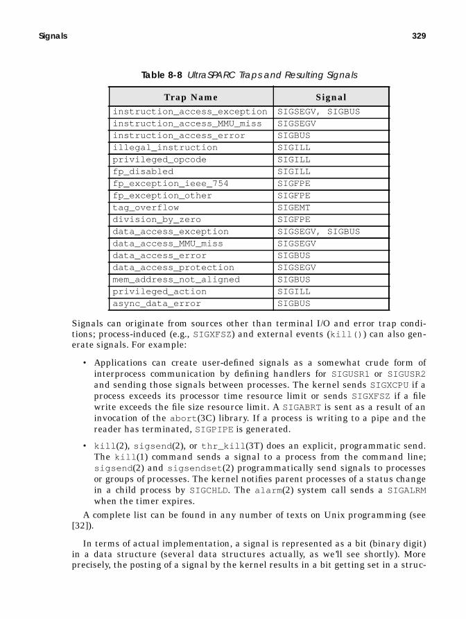
Signals 329
Signals can originate from sources other than terminal I/O and error trap condi-tions; process-induced (e.g., SIGXFSZ) and external events (kill() ) can also gen-erate signals. For example:
• Applications can create user-defined signals as a somewhat crude form ofinterprocess communication by defining handlers for SIGUSR1 or SIGUSR2and sending those signals between processes. The kernel sends SIGXCPUif aprocess exceeds its processor time resource limit or sends SIGXFSZ if a filewrite exceeds the file size resource limit. A SIGABRT is sent as a result of aninvocation of the abort (3C) library. If a process is writing to a pipe and thereader has terminated, SIGPIPE is generated.
• kill (2), sigsend (2), or thr_kill (3T) does an explicit, programmatic send.The kill (1) command sends a signal to a process from the command line;sigsend (2) and sigsendset (2) programmatically send signals to processesor groups of processes. The kernel notifies parent processes of a status changein a child process by SIGCHLD. The alarm (2) system call sends a SIGALRMwhen the timer expires.
A complete list can be found in any number of texts on Unix programming (see[32]).
In terms of actual implementation, a signal is represented as a bit (binary digit)in a data structure (several data structures actually, as we’ll see shortly). Moreprecisely, the posting of a signal by the kernel results in a bit getting set in a struc-
Table 8-8 UltraSPARC Traps and Resulting Signals
Trap Name Signalinstruction_access_exception SIGSEGV, SIGBUSinstruction_access_MMU_miss SIGSEGVinstruction_access_error SIGBUSillegal_instruction SIGILLprivileged_opcode SIGILLfp_disabled SIGILLfp_exception_ieee_754 SIGFPEfp_exception_other SIGFPEtag_overflow SIGEMTdivision_by_zero SIGFPEdata_access_exception SIGSEGV, SIGBUSdata_access_MMU_miss SIGSEGVdata_access_error SIGBUSdata_access_protection SIGSEGVmem_address_not_aligned SIGBUSprivileged_action SIGILLasync_data_error SIGBUS

330 The Solaris Multithreaded Process Architecture
ture member at either the process or thread level. Because each signal has aunique signal number, we use a structure member of sufficient width, such that wecan represent every signal by simply setting the bit that corresponds to the signalnumber of the signal we wish to post. For example, set the 17th bit to post signal17, SIGUSR1 (which is actually bit number 16, because they start with 0, and thesignal numbers start with 1).
Since more than 32 signals are now possible in the Solaris environment, a longor int data type is not wide enough to represent each possible signal as a uniquebit, so we need a data structure. (In 64-bit Solaris 7, a long is a 64-bit data type,but the signal code was developed prior to the implementation of 64-bit datatypes.) Several of the process data structures use the k_sigset_t data structure,defined in /usr/include/signal.h , to store the posted signal bits. k_sigset_tis an array of two unsigned long data types (array members 0 and 1), providing abit width of 64 bits, as shown in Figure 8.21. sigset_t , defined in signal.h , isessentially the same thing as a k_sigset_t , except that it is twice the size (fourarrays in sigset_t as opposed to two in k_sigset_t ).
Figure 8.21 Signal Representation in k_sigset_t Data Type
8.7.1 Signal Implementation
Our discussion of the signal implementation in Solaris reflects code that firstappeared in Solaris 2.5. The discussion is applicable to all releases from Solaris 2.5up to and including Solaris 7.
The multithreaded architecture of the Solaris environment made for some inter-esting challenges in developing a means of supporting signals that comply with theUnix signal semantics as defined by industry standards such as POSIX. Signalstraditionally go through two well-defined stages: generation and delivery. Signalgeneration is the point of origin of the signal—the sending phase. A signal is saidto be delivered when whatever disposition has been established for the signal isinvoked, even if it is to be ignored. If a signal is being blocked, thus postponingdelivery, it is considered pending.
User threads in the Solaris environment, created by explicit calls to eitherthr_create (3T) or pthread_create (3T), each have their own signal mask.Threads can choose to block signals independently of other threads executing inthe same process; thus, different threads may be available to take delivery of dif-ferent signals at various times during process execution. The threads libraries
typedef struct {unsigned long __sigbits[2];
} k_sigset_t;
__sigbits[0]__sigbits[1]
0313263
signals posted by setting bitnumber that corresponds to signalnumber

Signals 331
(POSIX and Solaris threads) provide the thr_sigsetmask (3T) andpthread_sigmask (3T) interfaces for establishing per-user thread signal masks.The disposition and handlers for all signals are shared by all the threads in a pro-cess, such that a SIGINT (for example), with the default disposition in place, willcause the entire process to exit. Signals generated as a result of a trap (SIGFPE,SIGILL , etc.) are sent to the thread that caused the trap. Asynchronous signals,which are all signals not defined as traps, are delivered to the first thread that isfound not blocking the signal.
The difficulty in implementing semantically correct signals in the Solaris envi-ronment arises from the fact that user-level threads are not visible to the kernel;thus, the low-level kernel signal code has no way of knowing which threads havewhich signals blocked and, therefore, no way of knowing which thread a signalshould be sent to. Some sort of intermediary phase needed to be implemented:something that had visibility both to the user thread signal masks and to the ker-nel. The solution came in the form of a special LWP that the threads library cre-ates for programs that are linked to libthread ; this LWP is called the aslwp (it’sactually an LWP/kthread pair, remember, they always travel in pairs). The imple-mentation of the aslwp extends the traditional signal generation and deliveryphases, by adding two additional steps: notification and redirection.
Generation -> Notification -> Redirection -> Delivery
Sending a signal (generation) to a process causes the aslwp to be notified, atwhich point the aslwp looks for a thread that can take delivery of the signal. Oncesuch a thread is located, the signal is redirected to that thread and can then bedelivered. The exception to this rule is the sending of synchronous or trap signals(listed in Table 8-8). A trap signal, such as a SIGSEGV, is not channeled throughthe aslwp, but rather is delivered to the LWP/kthread that caused the trap, andfrom there up to the user thread.
Before we delve into the mechanics of signal delivery, we should look at the datatypes used to support signals in the process, LWP/kthread, and user thread struc-tures.
Figure 8.22 illustrates all the structures, data types, and linked lists required tosupport signals in Solaris. There are, of course, differences between a multi-threaded process and a nonthreaded process. The figure shows a multithreadedprocess (with only one user thread, for simplicity). Nonthreaded processes are a lit-tle easier to deal with because they do not require the use of the aslwp for signalredirection. The major data structures shown in Figure 8.22 are described in Table8-9 and Table 8-10.
Table 8-9 sigqueue Structure
Field Name Data Type Descriptionsq_next pointer Pointer to sigqueue structure for linked listsq_info siginfo struct Embedded siginfo structure (see below)
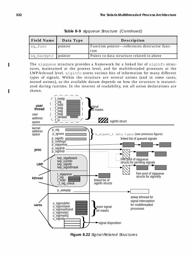
332 The Solaris Multithreaded Process Architecture
The sigqueue structure provides a framework for a linked list of siginfo struc-tures, maintained at the process level, and for multithreaded processes at theLWP/kthread level. siginfo stores various bits of information for many differenttypes of signals. Within the structure are several unions (and in some cases,nested unions), so the available datum depends on how the structure is instanti-ated during runtime. In the interest of readability, not all union declarations areshown.
sq_func pointer Function pointer—references destructor func-tion
sq_backptr pointer Points to data structure related to above
Table 8-9 sigqueue Structure (Continued)
Field Name Data Type Description
proc
userthread
LWP
kthread
p_sigp_ignorep_siginfo
p_sigqhdrp_signhdr
}
lwp_sigaltstacklwp_curinfolwp_siginfolwp_sigoldmask
t_sigqueuet_sigt_hold_t_sig_check
p_aslwptp
k_sigset_t data types (see previous figure)
uarea u_signodeferu_sigonstacku_sigresethandu_sigrestartu_sigmask[]u_signal } signal disposition
aslwp kthread forsignal interception
linked list of queued signals
free pool of sigqueuestructs for pending signals
free pool of sigqueuestructs for signotify
siginfo struct
t_nosigt_sigt_holdt_psigt_ssigt_bsigt_olmaskt_si
}signalbit masks
useraddressspace
kerneladdressspace
linked list ofsiginfo structs
for multithreadedprocesses}more signal
bit masks
p_notifsigsp_sigqueue
Figure 8.22 Signal-Related Structures

Signals 333
The siginfo data is available to processes (well, programs really) that need toknow more about the reason a signal was generated. The sigaction (2) systemcall programmatically provides this information. An optional SA_SIGINFO flag (inthe sa_flags field of the sigaction structure) results in two additional argu-ments being passed to the signal handler (assuming of course that the signal dis-position has been set up to be caught). The first argument is always the signalnumber. A non-NULL second argument is a pointer to a siginfo structure(described in Table 8-10), and a third argument is a pointer to a ucontext_t datastructure, which contains hardware context information (stack pointer, signalmask, and general register contents) about the receiving process when the signalwas delivered. The siginfo data can be useful for debugging when a trap signalis generated; for example, in the case of a SIGILL or SIGFPE, more specific infor-mation about the underlying reason for the trap can be gleaned from the data thekernel plugs into siginfo when getting ready to send a signal. (See the sigac-tion (2), siginfo (5), and ucontext (5) manual pages.)
Table 8-10 siginfo Structure
Structure orUnion
FieldName
Data Type Description
struct siginfo si_signo integer Signal numbersi_code integer A code related to the signalsi_errno integer System call errno
union _proc Proc union datum instantiated inkill (2), SIGCLD, and sigqueue()
pid pid_t PIDstatus int SIGCLD –child exit statusstime clock_t child system timeutime clock_t child user timeuid uid_t UID, killvalue int
union _fault Fault union for SEGV, BUS, ILL ,TRAP, FPE
addr caddr_t fault addresstrapno int trap numberpc caddr_t program counter
union _file File union for POLL, XFSZfd int file descriptorband int band
union _proffaddr caddr_t last fault addresststamp timestruct timestampsyscall short system call number
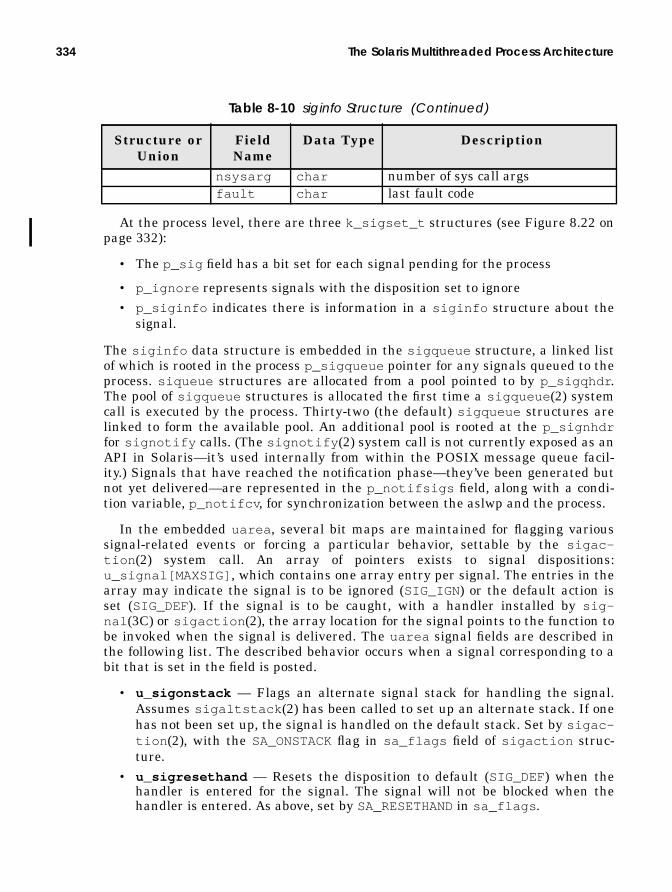
334 The Solaris Multithreaded Process Architecture
At the process level, there are three k_sigset_t structures (see Figure 8.22 onpage 332):
• The p_sig field has a bit set for each signal pending for the process
• p_ignore represents signals with the disposition set to ignore• p_siginfo indicates there is information in a siginfo structure about the
signal.
The siginfo data structure is embedded in the sigqueue structure, a linked listof which is rooted in the process p_sigqueue pointer for any signals queued to theprocess. siqueue structures are allocated from a pool pointed to by p_sigqhdr .The pool of sigqueue structures is allocated the first time a sigqueue (2) systemcall is executed by the process. Thirty-two (the default) sigqueue structures arelinked to form the available pool. An additional pool is rooted at the p_signhdrfor signotify calls. (The signotify (2) system call is not currently exposed as anAPI in Solaris—it’s used internally from within the POSIX message queue facil-ity.) Signals that have reached the notification phase—they’ve been generated butnot yet delivered—are represented in the p_notifsigs field, along with a condi-tion variable, p_notifcv , for synchronization between the aslwp and the process.
In the embedded uarea , several bit maps are maintained for flagging varioussignal-related events or forcing a particular behavior, settable by the sigac-tion (2) system call. An array of pointers exists to signal dispositions:u_signal[MAXSIG] , which contains one array entry per signal. The entries in thearray may indicate the signal is to be ignored (SIG_IGN ) or the default action isset (SIG_DEF). If the signal is to be caught, with a handler installed by sig-nal (3C) or sigaction (2), the array location for the signal points to the function tobe invoked when the signal is delivered. The uarea signal fields are described inthe following list. The described behavior occurs when a signal corresponding to abit that is set in the field is posted.
• u_sigonstack — Flags an alternate signal stack for handling the signal.Assumes sigaltstack (2) has been called to set up an alternate stack. If onehas not been set up, the signal is handled on the default stack. Set by sigac-tion (2), with the SA_ONSTACKflag in sa_flags field of sigaction struc-ture.
• u_sigresethand — Resets the disposition to default (SIG_DEF) when thehandler is entered for the signal. The signal will not be blocked when thehandler is entered. As above, set by SA_RESETHAND in sa_flags .
nsysarg char number of sys call argsfault char last fault code
Table 8-10 siginfo Structure (Continued)
Structure orUnion
FieldName
Data Type Description

Signals 335
• u_sigrestart — If inside a system call when the signal is received, restartsthe system call. This behavior does not work for all system calls, only thosethat are potentially “slow” (e.g., I/O-oriented system calls—read (2),write (2), etc). Interrupted system calls typically result in an error, with theerrno being set to EINTR. Set by SA_RESTART in sa_flags .
• u_signodefer — Does not block subsequent occurrences of the signal whenit is caught. Normally, a signal is blocked when it has been delivered and ahandler is executed. Set by SA_NODEFER in sa_flags .
• u_sigmask[] — Signals that have been caught and are being held while ahandler is executing.
• u_signal[] — Signal dispositions.
The LWP stores the current signal in lwp_cursig and stores a pointer to a sig-queue struct with the siginfo data for the current signal in lwp_curinfo ,which is used in the signal delivery phase.
Other fields include a stack pointer if an alternate signal stack,lwp_sigaltstack , is set up by a call to sigaltstack (2). It is sometimes desir-able for programs that do their own stack management to handle signals on analternate stack, as opposed to the default use of the thread’s runtime stack(SA_ONSTACKthrough sigaction (2) when the handler is set). The kernel threadmaintains two k_sigset_t members: t_sig and t_hold . t_sig has the samemeaning as p_sig at the process level, that is, a mask of pending signals; t_holdis a bit mask of signals to block.
In addition, t_sigqueue points to a sigqueue for siginfo data. A signal’ssiginfo structure will be placed either on the process p_sigqueue or thekthread’s t_sigqueue . The kthread t_sigqueue is used in the case where anon-NULL kthread pointer has been passed in the kernel signal code, indicating adirected signal, for example, a multithreaded process with more than one LWP.
Finally, for multithreaded processes, the user thread (not to be confused withthe kernel thread) maintains signal masks for pending signals (t_psig ), sent sig-nals (t_ssig ), bounced signals (t_bsig —more on bounced signals later), and sig-nals to be blocked (t_hold ). There is also a siginfo structure for deferredsignals, referenced as t_si .
Clearly, there appears to be more than a little redundancy in the signal supportstructure members spread throughout the various entities that exist within thecontext of a process. This redundancy is due to the requirements for support of themultithreaded model and the fact that different signals get posted to differentplaces, depending on the signal itself and the source. Earlier in the discussion, weprovided several examples of why some signals are sent and where they originate.Asynchronous signals could originate from a user or from various places in thekernel. Signals that are sent from userland (e.g., kill (1), kill (2), sigqueue (2))are sent to the process. Some signals that originate in the kernel are directed to aparticular LWP/kthread; for example, the kernel clock interrupt handler may send

336 The Solaris Multithreaded Process Architecture
a SIGPROFor SIGVTALRMdirectly to a LWP/kthread. The pthread_kill (3T) andthr_kill (3T) threads library interfaces provide for sending asynchronous signalsto a specific user thread. The STREAMS subsystem sends SIGPOLL and SIGURGtothe process when appropriate (e.g., polled event occurs or urgent out-of-band mes-sage is received).
Regardless of the source of the signal, the ultimate delivery mechanism throughthe operating system is the kernel sigtoproc() function, which takes up to fourarguments: a process pointer, a kernel thread pointer, the signal number, and anoptional flag, fromuser , which indicates whether the source of the signal was thekernel or user. Signals that should be directed to a kthread/LWP call sigto-

Signals 337
proc() with a valid kthread pointer. A NULL kthread pointer indicates the signalshould be posted to the process. Let’s take a look at the code flow of sigtoproc() .
Before moving on, we want to reiterate a few key points: a refresher on what theforest looks like before we examine the trees.
First, a high-level view of what sigtoproc() does. The sigtoproc() kernelfunction posts a signal to a process or kthread, which simply means “set the bit inthe process’s p_sig field that corresponds to the signal.” If sigtoproc() is passeda non-NULL kernel thread pointer and the signal is directed, the signal is posted tothe LWP/kthread, meaning the correct bit gets set in the kthread t_sig field. Non-
sigtoproc(proc pointer, kthread pointer, int signal, fromuser flag) if (signal == SIGKILL) /* kill signal */ Set SKILLED in p_flags Set kthread pointer to NULL else if (signal == SIGCONT) /* continue - job control */ Delete queued siginfo structs for pending STOP signals (SIGSTOP, SIGTSTP, SIGTTOU, SIGTTIN) if (process has an aslwp thread) /* multithreaded processes */ Clear SIGSTOP, SIGTSTP, SIGTTOU, SIGTTIN in aslwp t_sig Clear SIGSTOP, SIGTSTP, SIGTTOU, SIGTIN in p_notifsigs if (process has more than one kthread) Loop through kthread linked list Delete siginfo structs for STOP, TSTP, TTOU, TTIN End loop else /* process has one kthread */ Clear STOP, TSTP, TTOU, TTIN in p_sig Clear p_stopsig if (process is multithreaded) Loop through kthread linked list if (thread is stopped due to job control) Set kthread t_schedflag to TS_XSTART Call setrun /* get the thread running */ End loop if (signal is STOP or TSTOP or TTOU or TTIN) Set kthread pointer to the process aslwp thread Delete any siginfo structures for queued SIGCONT if (process is multithreaded) Clear pending SIGCONT in aslwp Clear pending SIGCONT in p_notifsigs Loop through linked list of kernel threads Delete queued SIGCONT siginfo structures Clear pending SIGCONT in t_sig End loop else /* process is not multithreaded */ Clear pending SIGCONT in p_sig if (signal is discardable) return if (process has an aslwp kernel thread) Set signal bit in aslwp t_sig Call eat_signal() else if (process is multithreaded) Set the signal bit in process p_sig Loop through linked list of kernel threads if (eat signal) break out of loop if (signal is SIGKILL) Try to run a kthread so signal can be delivered End LoopEnd sigtoproc

338 The Solaris Multithreaded Process Architecture
directed asynchronous signals are channeled through the aslwp for redirection tothe first user thread it can find that’s not masking the signal. Clearly, that’s anoversimplification, as the previous pseudocode flow of the function indicates, butit’s a good place to start.
The second key point to keep in mind is the different phases involved in process-ing signals. We mentioned earlier how the Solaris implementation extends the tra-ditional Unix model of signal generation and delivery by imposing a notificationand redirection phase, to support the multithreaded model while maintaining asemantically correct signal implementation. Once a signal has reached its finaldestination—meaning that the siginfo structure has been placed on the queueand the correct bit has been set in the process, LWP/kthread, or user thread—theexistence of a signal must be made known to the process/thread so action can betaken. When you consider that a signal is represented by the setting of a bit in adata structure, it seems intuitive that the kernel must periodically check for setbits (i.e., pending signals). This is, in fact, precisely how delivery is done. The ker-nel checks for posted signals at several points during the typical execution flow ofa process:
• Return from a system call
• Return from a trap
• Wake up from a sleep
In essence, the determination of the existence of a signal is a polling process,where the signal fields in the process p_sig and kthread t_sig fields are exam-ined frequently for the presence of a set bit. Once it is determined that a signal isposted, the kernel can take appropriate action, based on the signal’s current dispo-sition in the context of the process that received it.
Figure 8.23 illustrates the process.
sigtoproc()
kill(2)
sigqueue(2)
variousplaces inthe kernel
uare
a
process
LWPkthread
userthread
Generation Notification Redirection Delivery
ISSIG checks
aslw
p
user modeexecution
syscall/trap
signalpending?
ISSIG
psig()
action
retu
rnSynchronous signals(e.g., SIGILL) are notchanneled throughthe aslwp.
Asynchronoussignals are postedfirst to the aslwpfor redirection.
p_sig (process)and t_sig inkthread.

Signals 339
Figure 8.23 High-Level Signal Flow
This signal flow explains why zombie processes cannot be killed (any horrormovie fan knows you can’t kill a zombie). A process must be executing in order totake delivery of a signal. A zombie process is, by definition, a process that has ter-minated. It exists only as a process table entry, with all of its execution state hav-ing been freed by the kernel.
A lot of the up-front work in sigtoproc() deals with job control and the termi-nal I/O signals. In compliance with the POSIX specifications, this behavior is docu-mented in the signal (5) manual page, which we summarize here: Any pendingSIGCONTsignals are discarded upon receipt of a SIGSTOP, SIGTSTP, SIGTTIN , orSIGTTOU signal, regardless of the disposition. The inverse is also true; if any ofthose four signals are pending when a SIGCONTis received, they are discarded,again regardless of the disposition. In both cases, the posted signal will be deliv-ered following the flow described in “Synchronous Signals,” below.
8.7.1.1 Synchronous Signals
Synchronous signals, or trap signals, originate from within the kernel trap han-dler. When an executing instruction stream causes one of the events described inTable 4.2, it is detected by the hardware and execution is redirected to a kerneltrap handler. The trap handler code populates a siginfo structure with theappropriate information about the trap and invokes the trap_cleanup() func-tion, where the function determines whether to stop the kthread/LWP because of adebugger “stop on fault” flag. The entry point into the kernel signal subsystem isthrough the trapsig() function, which is executed next. If the signal is maskedor the disposition has been set to ignore, then trapsig() unmasks the signal andsets the disposition to default. The siginfo structure is placed on the kthread’st_sigqueue list, and sigtoproc() is called to post the signal.
With reference to the sigtoproc() pseudocode flow on page 337, the postingof a trap signal occurs at the segment shown below.
The signal will be added to the t_sig field in the kthread, and the eat_signal()function is invoked. The job of eat_signal() is to make sure the kthread is goingto take delivery of the signal quickly—a sleeping thread is made runnable, takenoff the sleep queue, and put on a dispatch queue, and the t_astflag in thekthread structure is set. The t_astflag will force the thread to check for a signalwhen execution resumes. With the signal now posted, sigtoproc() is done, andthe code returns to trap_cleanup() . The cleanup code invokes theISSIG_PENDING macro, which will determine from the bit set in the t_sig field
/* sigtoproc was passed a non-NULL kthread pointer, * indicating a directed signal */Set signal bit in aslwp kernel threadUs t_sig (sigaddset())Call eat_signal()

340 The Solaris Multithreaded Process Architecture
that a signal has been posted. Once the macro establishes the presence of the sig-nal, it invokes the kernel psig() function to handle actual delivery.
The system defines several macros for speeding up the examination of the procp_sig and kthread t_sig fields for the presence of a posted signal. The defini-tions below are from /usr/include/sys/proc.h .
As you can see, ISSIG and ISSIG_FAST resolve to ISSIG_PENDING, which per-forms a logical OR on the p_sig and t_sig fields, logically ANDing that resultwith the return value of issig(why) .
The issig() function is the last bit of work the kernel does before actual sig-nal delivery. The “why” argument passed to issig will be one of JUSTLOOKINGorFORREAL. The, JUSTLOOKINGflag causes issig() to return if a signal is pendingbut does not stop the process if a debugger requests a stop. In the case of a trapsignal, issig() is passed FORREAL, which causes the process to be stopped if astop has been requested or a traced signal is pending. Assuming no special debug-ger flags or signal tracing, the kernel invokes the psig() signal delivery functionto carry out the delivery phase, based on the current disposition of the signal.
8.7.1.2 Asynchronous Signals
Asynchronously generated (interrupt) signals can originate from a user commandor program or from somewhere inside the kernel. Such signals are channeledthrough the aslwp in multithreaded programs. For nonthreaded code, the signal isdelivered to the kernel thread within the process.
The aslwp essentially loops forever in an internal call to a function similar tothe sigwait (2) system call. When a signal is generated by kill (1), kill (2),thr_kill (3T), sigqueue (2), etc., or from within the kernel, the sigtoproc()
#define ISSIG(t, why)ISSIG_FAST(t, ttolwp(t), ttoproc(t), why)
/* * Fast version of ISSIG. *1. uses register pointers to lwp and proc instead of reloading them. *2. uses bitwise OR of tests, since the usual case is that none of them * are true; this saves orcc’s and branches. * are true; this saves orcc’s and branches. *3. loads the signal flags instead of using sigisempty() macro which does * a branch to convert to boolean. */#define ISSIG_FAST(t, lwp, p, why)\(ISSIG_PENDING(t, lwp, p) && issig(why))
#define ISSIG_PENDING(t, lwp, p)\((lwp)->lwp_cursig |\ (p)->p_sig.__sigbits[0] |\ (p)->p_sig.__sigbits[1] |\ (t)->t_sig.__sigbits[0] |\ (t)->t_sig.__sigbits[1] |\ (p)->p_stopsig |\ ((t)->t_proc_flag & (TP_PRSTOP|TP_HOLDLWP|TP_CHKPT|TP_PAUSE)) | \ ((p)->p_flag & (EXITLWPS|SKILLED|HOLDFORK1|HOLDWATCH)))
Header File <sys/proc.h>

Signals 341
function is invoked to post the signal. After sigtoproc() completes the up-frontwork for dealing with the tty and job control signals, it determines whether anaslwp exists within the process and sets the correct signal bit in the aslwp’s t_sigsignal mask.
This action wakes up the aslwp, which is looping on an internal sigwait func-tion. When the aslwp first enters its wait function, it unmasks all signals (clearsall the bits in the kernel-thread signal mask t_hold ). It checks for any pendingsignals in the notification mask, maintained at the process level in p_notifsigs .Recall that notification follows signal generation and precedes redirection anddelivery. Once the aslwp detects the posted signal, it adds it to the notificationmask, signifying that it has been notified but that the signal has not yet beendelivered. The internal sigwait code moves a new signal from the t_sig field inthe aslwp’s kernel thread to the p_notifsigs bit mask.
With the signal set in the notification mask, it’s time for the aslwp to look for athread that isn’t masking the signal so it can be delivered. An internalthr_sigredirect function conducts this procedure by adding the signal to theuser thread’s t_bsig field (a “bounced” signal; it was bounced from the aslwp tothe user thread).
That done, the signal must be moved to the kthread/LWP to be detected by theISSIG macro. Remember, the kernel examines the kthread t_sig and the processp_sig fields for a posted signal. The kernel cannot “see” user threads, so an addi-tional function call is invoked to move the signal to the kthread’s t_sig field. Thefunction itself is a kernel-level redirect routine; it redirects the signal based on thelwpid, which is maintained in the user thread structure. If the user thread isn’tcurrently running on an LWP/kthread, then the signal remains pending in theuser thread’s t_bsig mask. The user-level threads library scheduler detects thepending signal when the user thread is scheduled on an LWP/kthread and invokesthe redirect function to post the signal at the LWP/kthread level.
Summarizing the sequence of events, we have a thread (aslwp) looping in afunction waiting for signals. Signal generation causes the wait function to movethe signal to a notification set, which completes the notification phase. The signalis then redirected, first at the user-thread level to the thread’s t_bsig field, andthen down to the LWP/kthread through a couple of redirect functions. Once postedat the kthread level, the signal is detected by means of the ISSIG macro calls,which are invoked on returns from system calls, traps, and on wakeups from asleep. If a signal is present, the macro calls the kernel psig() function, which iswhere signal delivery takes place.
psig() sets up the correct state (stack, registers) for the handling of the signalin two cases: if a handler has been set up by sigaction (2) or signal (3) or if thedefault disposition of the signal requires something other than ignoring the signal(like stopping the process, terminating the process, or terminating and generatinga core file). Remember, signal disposition is processwide—whatever signal handlercode runs potentially affects all the threads in a multithreaded process.

342 The Solaris Multithreaded Process Architecture
8.7.2 SIGWAITING: A Special Signal
The execution of a user-level thread requires the availability of an LWP/kthreadfor the user thread to get scheduled onto. That part is done by a dedicated schedul-ing thread in the threads library. (User threads have their own priority schemeand a threads library dispatcher that selects the next user thread to execute.There are quite a few similarities architecturally between the threads library dis-patcher and the kernel dispatcher.) Threads do not need to be bound to an LWPwhen created, and it is not uncommon in multithreaded programs to have manyunbound threads scheduled onto a smaller pool of LWPs. Deciding on the optimalratio of LWPs to user threads is not always straightforward, and suboptimal per-formance can result from having either too many or too few LWPs. Excess LWPsare more work for the kernel to manage; not enough LWPs can result in runnableuser threads hanging around waiting for an LWP to become available, slowingoverall execution.
The thr_setconcurrency (3T) interface enables a programmer to providehints to the operating system as to how many LWPs it should make available forthe process. LWPs can also be created in the thr_create (3T) call (THR_NEW_LWPflag), and a user thread can be bound to an LWP with the THR_BOUND flag set.
8.8 Sessions and Process Groups
The kernel creates several groupings of processes representing different abstrac-tions by which it manages various aspects of process control. In addition to thefamily hierarchy of process parent/child, the kernel implements process groups andlinks processes associated with the same terminal session. Both sessions and pro-cess groups are collections of one or more processes that have a common relation-ship or ancestry. The two abstractions, sessions and process groups, are intimatelyrelated to each other and tied closely to the signal and terminal (tty) subsystems.
Historically, process groups and sessions arose from the desire to increase thepower and flexibility available to Unix users: developers, systems administrators,and end users. The groups and sessions enable users to run multiple, concurrentjobs from a single login session, to place jobs in the background, bring them intothe foreground, suspend and continue jobs, and toggle which job is actively con-nected to the control terminal (the foreground job).
The kernel maintains process groups and session links to establish an eventnotification chain in support of job control shells. The signal facility starts andstops processes (or jobs in this context), puts processes in the background, andbrings them into the foreground. Using the process group linkage makes signaldelivery to multiple, related processes much easier to implement. Adding the ses-sions abstraction puts a boundary between the process group jobs and the interac-tive login session.

Sessions and Process Groups 343
Every process belongs to a process group, identified by the p_pgidp pointer inthe process structure, and is established in the kernel fork code when the processis created. Thus, processes in the same parent/child/sibling chain, by defaultbelong to the same process group. The process group ID (PGID) is the process PIDof the process group leader. That is, every process group has a process groupleader, where the PID and PGID are the same. Sibling processes are assigned thePGID of the parent process; thus, the PGID of siblings will be the PID of the pro-cess group leader.
When a stand-alone process is started from a shell, it is placed in its own pro-cess group with the setpgid (2) system call, invoked from the shell code after theprocess is created with fork (2). Processes grouped on a command line (e.g., a pipe-line) will all be part of the same process group. The first process created becomesthe process group leader of the new process group, and subsequent processes in thepipeline are added to the group. Here’s a quick example.
ksh> cat report_file | sort -1 +2 | lp &
The shell in the above example is the Korn shell. Three processes will be cre-ated, one each for cat (1), sort (1), and lp (1), and all placed in the same processgroup. That group will be put in the background, where the above job crunchesaway while an interactive user session continues. In this context, a job refers toprocesses in the same process group working toward a common goal and con-nected by pipes. The proper job control keystrokes (Control-Z in /bin/ksh ) couldstop all the processes in the group, sending a SIGTSTP signal to all the processesin the process group. The setpgid (2) system call places the processes in the sameprocess group. Although process groups are most commonly created from the user’sshell, an application program can use the setpgid (2) or setpgrp (2) system callsto create new process groups.
Process groups can be in the foreground or the background. The foreground pro-cess group is the process group that has access to the controlling terminal, mean-ing that input characters are sent to the foreground process group and outputcharacters (writes to stdout and stderr) are sent to the controlling terminal. Back-ground process groups cannot read from or write to the controlling terminal. Anattempt to read from or write to the controlling terminal by a process in a back-ground process group results in a SIGTTIN (read) or SIGTTOU (write) signal fromthe kernel to the processes in the background process group. The default disposi-tion for these signals is to stop the processes.
Processes belonging to the same process group are linked on a doubly linked listby pointers in the process structure: p_pglink (points to the next process in theprocess group), and p_ppglink (points to the previous process). Figure 8.24 illus-trates the process group links and the ID name space links (pointers to the PIDstructures).

344 The Solaris Multithreaded Process Architecture
Figure 8.24 Process Group Links
Figure 8.24 illustrates a process as the only member of a process group (upper dia-gram), and three processes in the same process group (lower diagram). The pro-cesses in the lower diagram that are not the process group leader obtain theirPGID by linking to the PID structure of the process group leader.
Process groups are a subset of sessions; a session has one or more processgroups associated with it. A session abstracts a process and the process’s controlterminal and extends the abstraction to include process groups. All the processgroups within a session have a common controlling terminal. Thus, all processesbelong to a process group and are associated with a session. Sessions areabstracted by the session data structure, which the process links to through itsp_sessp pointer. As with process groups, sessions are inherited through thefork() code.
The control terminal is typically the login terminal the user connects to whenlogging in to a Solaris system. The phrase control terminal is more an abstraction
p_pglinkp_ppglinkp_pidpp_pgidp
pid_slot:orphaned:inactivepid_idpid_pglinkpid_linkpid_ref
p_pglinkp_ppglinkp_pidpp_pgidp
p_pglinkp_ppglinkp_pidpp_pgidp
pid_slot:orphaned:inactivepid_idpid_pglinkpid_linkpid_ref
pid_slot:orphaned:inactivepid_idpid_pglinkpid_linkpid_ref
process structures
pid_structure
A process that is the leaderand only member of itsprocess group links bothp_pidp and p_pgidp tothe PID structure.
PID
has
h ch
ain
pid_slot:orphaned:inactivepid_idpid_pglinkpid_linkpid_ref
pid_slot:orphaned:inactivepid_idpid_pglinkpid_linkpid_ref
p_pglinkp_ppglinkp_pidpp_pgidp
PID hash chain
Processes in the same process group link to the PID structure of theprocess group leader for the PGID. process
groupleader

Sessions and Process Groups 345
these days (as opposed to an actual, physical terminal) because most login ses-sions are network based and the terminal is a window on the screen of a worksta-tion, implemented by one of many terminal emulation utilities (xterm, dtterm,shelltool, cmdtool, etc.). Network logins (rlogin (1), telnet (1), etc.) are sup-ported through the use of pseudoterminals, which are software abstractions thatprovide terminal I/O semantics over a network link or through a window managerrunning under the X Window System. (X windows is the network-transparent win-dowing system that virtually all Unix vendors on the planet use for their Graphi-cal User Interface (GUI)-based workstation environments).
A control terminal is associated with a session, and a session can have only onecontrol terminal associated with it. A control terminal can be associated with onlyone session. We sometimes refer to a session leader, which is the foreground pro-cess or process group that has established a connection to the control terminal.The session leader is usually the login shell of the user. It is the session leader thatdirects certain input sequences (job control keystrokes and commands) from thecontrol terminal to generate signals to process groups in the session associatedwith the controlling terminal. Every session has a session ID, which is the PGID ofthe session leader.
The session abstraction is implemented as a data structure, the session struc-ture, and some support code in the kernel for creating sessions and managing thecontrol terminal. The session structure includes the following:
• The device number of the control terminal device special file• A pointer to the vnode for the control terminal device, which links to the
snode, since it’s a device• UID and GID of the process that initiated the session
• A pointer to a credentials structure, which describes the credentials of theprocess that initiated the session
• A reference count
• A link to a PID structure
The session ID is derived in the same way as the PGID for a process. That is, thesession structure will link to the PID structure of the process that is attached tothe control terminal, the login shell in most cases. Note that daemon processes,which do not have a control terminal, will have a NULL vnode pointer in the ses-sion structure. All processes will thus link to a session structure, but processeswithout control terminals will not have the vnode link, that is, they have no con-nection to a control device driver.
Figure 8.25 provides the big picture, illustrating a login session with a processgroup and showing the links to the related data structures.

346 The Solaris Multithreaded Process Architecture
Figure 8.25 Process and Session Structure Links
Figure 8.25 provides two illustrations. The top diagram shows some detail of thedata structures and links for a simple case of a login session with two processgroups. One process group has only one process, the login shell. The other processgroup has three processes. They all link to the session structure, which connects tothe device and device driver through the s_vp vnode pointer. The session leader isthe login shell, and the session ID is the PID of the login shell.
The lower illustration is a broader view, encapsulating a login session (a ses-sion) with a shell process in its own process group, plus three additional processgroups. One process group is in the foreground, thus attached to the control termi-
p_pglinkp_ppglinkp_pidpp_pgidpp_sessp
p_pglinkp_ppglinkp_pidpp_pgidpp_sessp
p_pglinkp_ppglinkp_pidpp_pgidpp_sessp
p_pglinkp_ppglinkp_pidpp_pgidpp_sessp
PID structsessionstruct
s_vps_sidp
process group
procstructs
login shell process
vnode snode links to device driver
login session
controlterminal
sessionstructure
loginshell
foregroundprocessgroup
backgroundprocessgroups
^z or bg put thisgroup in thebackgroundfg job # brings
another groupinto the foreground
processes
processgroups

Sessions and Process Groups 347
nal, receiving characters typed and able to write to the terminal screen. Job con-trol shells use a ^Z (Control-Z) key sequence to place a foreground process/processgroup in the background. A SIGTSTP signal is sent to all the processes in thegroup, and the processes are stopped. If a process sets up a signal handler andcatches SIGTSTP, the handler is invoked and governs the process behavior.
The session leader (e.g., the shell) handles the communication link to the con-trol terminal by using library calls that translate to ioctl() routines into theSTREAMS subsystem. (The character device drivers in Solaris for serial terminalsand pseudoterminals are STREAMS based.) The standard C library includestcsetpgrp (3) and tcgetpgrp (3) interfaces for setting and getting the processgroup ID for a control terminal.
When processes or process groups are moved from the background into the fore-ground, the session leader issues a tcsetpgrp (3) call to direct the control termi-nal to the new foreground process. The tcsetpgrp (3) call results in an ioctl()call into the tty/pty driver code with the TIOCSPGRPflag, which in turn enters theSTREAMS subsystem, calling the strsetpgrp() function (STREAM set processgroup). The data structures associated with the control terminal include aSTREAM header structure, stdata , which contains a pointer to a PID structure forthe foreground process group. When a new process or process group is placed intothe foreground, the sd_pgidp pointer is set to reference the PID structure of theprocess group leader in the new foreground process group. In this way, the controlterminal is dynamically attached to different process groups running under thesame session.
The signal mechanism in the kernel that delivers signals to groups of processesis the same code used for other signal delivery. A pgsignal() (process group sig-nal) interface is implemented in the kernel. The function follows the pointers thatlink processes in a process group and calls the generic sigtoproc() function ineach pass through the loop, causing the signal to be posted to each process in theprocess group.

348 The Solaris Multithreaded Process Architecture

9
THE SOLARIS KERNELDISPATCHER
In the previous chapter, we discussed (among other things) the creation and ter-mination of processes and the LWPs and kernel threads within the process. Nowwe’ll talk about what happens in between creation and termination: the schedul-ing and execution phase, managed by the Solaris kernel dispatcher (a.k.a. sched-uler).
The framework on which the Solaris 2.X scheduler is built is rooted in the UnixSVR4 scheduler, which represents a complete rework of the traditional Unix sched-uler. The rework incorporated the notion of a scheduling class, which defines thescheduling policies and systemwide priority range for kernel threads in a particu-lar scheduling class. The implementation of dispatcher tables for storing theparameters used by the scheduler code was introduced. For each scheduling class,there exists a table of values and parameters the dispatcher code uses for estab-lishing the priority of a kernel thread, which ultimately drives the thread’s place-ment on a dispatch queue—the Solaris queues of runnable threads waiting for anavailable processor.
In this chapter, we examine the implementation of the kernel scheduler, or dis-patcher, in Solaris. We discuss the scheduling classes, the dispatch tables, and thekernel functions that provide the dispatcher infrastructure, including the kernelthread priority scheme and priority algorithms. We take a look at sleep queues andthe kernel sleep/wakeup facilities. Finally, we discuss innovative features in thekernel, such as scheduler activations.
349

350 The Solaris Kernel Dispatcher
9.1 Overview
The Solaris kernel scheduler provides a rich set of features and innovations thatcontribute significantly to the speed and scalability of the operating system. TheSolaris kernel is preemptive; that is, the execution of an operating system kernelthread, or user thread, can be preempted if a higher priority thread becomes run-nable. This feature minimizes dispatch latency and is a key component to theimplementation of the real-time scheduling class. The preemption mechanism isapplied across the entire range of system priorities. In general, if a thread of ahigher (better) priority than all threads currently executing becomes runnable, apreemption will occur, forcing the executing thread to relinquish the processor sothe higher priority thread can run.
The process of moving a kernel thread on and off a processor (CPU) is referredto as context switching, and the Solaris kernel tracks both involuntary contextswitches and voluntary context switches. An involuntary context switch occurswhen a thread is preempted (because a better priority thread has transitioned tothe runnable state) or when an executing kernel thread uses up its allotted timequantum. Voluntary context switches result from a thread executing a blockingsystem call, such as a file read, where the thread will be context-switched off theprocessor and placed on a sleep queue. When the event a thread is sleeping (block-ing) for occurs, a wakeup mechanism notifies the thread and places it back on arun queue, where it will be scheduled onto a processor, based on its global priorityas compared to other runnable threads.
Additionally, a scalable queueing mechanism is employed for runnable threads.Rather than implementing a single, monolithic queue to hold all runnable threadssystemwide, the Solaris kernel creates a set of dispatch queues for every processoron a system. Access to the per-processor queues is synchronized by means of locksthat exist at the queue level (as opposed to a single dispatch queue lock), provid-ing concurrency on queue manipulation functions.
The Solaris kernel dispatcher implements additional features that enhance theoverall usability and flexibility of the operating system:
• Scheduling classes. Kernel threads have a scheduling class and priority.Different scheduling classes provide different scheduling policies and priorityboundaries.
• Intuitive priority scheme. Higher priorities are better priorities (the tradi-tional Unix implementation was so designed that lower priorities were betterpriorities). The kernel defines a range of global priorities, 0–169. Within thatglobal priority range, a given scheduling class is assigned a subset of the totalnumber of global priorities, as shown in Figure 9.1.

Overview 351
Figure 9.1 Global Priority Scheme and Scheduling Classes
The priority assignments for each scheduling class are shown in Table 9-1.
• Real-time support. Solaris now provides support for real-time applications,which require a predictable, bounded dispatch latency (the elapsed timebetween the time when a thread needs to run and the time when it actuallybegins executing on a processor).
• Table-driven scheduler parameters. You can now “tune” the dispatcherfor specific application requirements by altering the values in the dispatchtable for a particular scheduling class. Note that the altering of the dispatchtable values can dramatically affect the behavior of an application, some-
Table 9-1 Scheduling Class Priority Ranges
ClassPriorityRange
GlobalPriorityRange
Scheduling Class
0 – 59 000 – 059 Timeshare (TS) and Interactive (IA )0 – 39 060 – 099 System (SYS)0 – 9 100 – 109 Interrupt threads (not really a sched-
uling class) if the RT class is notloaded
0 – 59 100 – 159 Realtime (RT)0-9 160 – 169 Interrupt threads if the RT class is
loaded
0
169
glob
al p
riorit
y ra
nge
timeshare
realtime
0
59
-60
+60
user priority range
interactive
-60
+60
user priority rangesystem
interruptuser priority rangeints
10
1

352 The Solaris Kernel Dispatcher
times for the worse if the user or administrator does not understand wellwhat the values mean. The SYS class is not implemented by a dispatchtable—it exists to allow user threads to execute at a higher priority undercertain conditions and to enable execution of non-user-related kernel threads.There is no tuning to be done because SYS class execution does not do timeslicing; there is no time quantum.
• Object-like implementation with loadable module support. Additionalscheduling classes can be created and added to the system without the needfor a complete kernel build (e.g., a batch scheduling class was created by SunCustomer Engineering for specific use).
• Scheduler activations. Innovative design features address several areas ofkernel scheduling, including improved communication between the user-levelthreads library and the kernel. Much more on this in “Scheduler Activations”on page 415.
• Priority inversion addressed. The issue of a higher-priority thread beingblocked from execution because a lower-priority thread is holding a resource(e.g., a lock) needed to run is described as priority inversion. The Solaris dis-patcher addresses this problem through priority inheritance.
• Scalable design. The major areas of the dispatcher and related data struc-tures implement fine-grained locking, providing excellent scalability on mul-tiprocessor platforms. For example, the kernel implements per-processordispatcher queues (run queues—queues of runnable kernel threads) withper-queue locking.
9.1.1 Scheduling Classes
Beginning with Solaris 2.0, the system shipped with three scheduling classes bydefault: system (SYS), timesharing (TS), and realtime (RT). Somewhere around theSolaris 2.4 time frame, the Interactive (IA ) scheduling class was added to providesnappier interactive desktop performance. The TS class provides the traditionalresource sharing behavior, such that all kernel threads on the system get theirshare of execution time, based on priority, time spent running, and time spentwaiting to run. Priorities are recalculated regularly, so threads that have had moreprocessor time have their priorities worsened and threads that have waited long-est have their priorities improved. The IA class implements the same basic sched-uling policies as TS (the same dispatch table is used, and most of the same code).IA -class threads are kernel threads that are created under a windowing system(e.g., CDE or OpenWindows) and get a priority boost advantage over TS classthreads.
The SYS class exists mostly for operating system kernel threads, such as thethreads created at boot time to provide various operating systems services(STREAMS processing, the thread reaper, etc.). SYS class threads are not timesliced and the priorities are fixed. A kernel thread in the SYS class runs until it

Overview 353
voluntarily surrenders the processor or is preempted when a higher-prioritythread becomes runnable. TS/IA threads can also be placed in the SYS class for ashort time if the thread is holding a critical resource; a RW lock, or a page lock ona memory page.
The RT class provides realtime scheduling behavior through a fixed priorityscheduling policy that has kernel preemption capabilities. RT class threads have ahigher global priority than that of TS and SYS threads. Real-time applicationsrequire a minimum, consistent, and deterministic dispatch latency, so when anevent occurs that a real-time thread needs to process, the thread gets priority overmost other threads (all but interrupt threads) on the system for execution on a pro-cessor.
Other kernel enhancements were needed to provide real-time application sup-port. The kernel had to be made preemptable, such that a real-time thread thatneeded a processor could cause the kernel to be preempted from what it was doingin order to allow the real-time thread to run. Most of the kernel is preemptable; afew critical code paths are non-preemptable, for example, when critical state infor-mation is saved or manipulated, as during a context switch.
The second thing that needed to be addressed was memory locking. A real-timethread cannot usually afford to be exposed to the latency involved in resolving apage fault, which causes thread execution to be suspended. This problem wasaddressed by addition of a memory locking facility, so that the developer of areal-time application can use the memcntl (2) system call or mlock (3C) libraryfunction to lock a range of pages in physical memory, thus keeping the memorypages resident in RAM.
These features, combined with processor sets, exclusive thread-to-processor setbinding (see Chapter 1, “System Overview”), and the ability to take a processor outof the interrupt pool, combine to make Solaris an outstanding choice for a greatmany real-time applications. A properly configured system, that is, a system withsufficient number of processors and memory, can provide a dispatch latency on theorder of 1 millisecond or less. For absolute minimum dispatch latency for areal-time process or thread, we recommend that you take the following steps.
• Size the system appropriately so the Solaris processor requirements for run-ning kernel threads for memory management, STREAMS processing, net-work and disk I/O, etc., can be met without impeding system performance.Remember, such processing is done by the kernel on behalf of the applica-tions it is running, which determine the load.
• Configure a processor set (Solaris 2.6 or later). The processor set can have oneprocessor if that meets the real-time application requirements.
• Disable interrupts to the processor set dedicated to running the RT pro-cess(es).
• Place your process or processes in the RT scheduling class, and bind them tothe processor set.

354 The Solaris Kernel Dispatcher
• If you have more than one RT thread or process, consider whether it needs tobe prioritized in terms of one thread or process getting processor time overanother, and use priocntl (1) to adjust RT priorities accordingly.
The preceding recommendations give your RT application exclusive access to aprocessor, or processors, depending on requirements and how many are configuredinto the processor set. You can add and remove processors from a processor setdynamically while the system and application are running.
Figure 9.2 shows the various scheduling classes supported by Solaris, in theirrelative positions with respect to global (systemwide) priorities. The range of inter-rupt priorities depends on whether or not the realtime class has been loaded.
Figure 9.2 Solaris Scheduling Classes and Priorities
The TS, IA , and RT scheduling classes are implemented as dynamically loadablekernel modules. The kernel binaries for the TS class are located in the /ker-nel/sched directory; the IA and RT classes reside in the /usr/kernel/scheddirectory. Note that most of the support functions for IA class threads are handledby the TS class code. There are only a few IA -class-specific routines. The SYSclassis an integral part of the kernel and thus is not built as a dynamically loadablemodule. The core dispatcher code is also an integral part of the kernel and isloaded with the initial unix and genunix objects at boot time.
From an architectural perspective, the scheduling class implementation followsan object-oriented design similar to the vfs/vnode architecture described inChapter 10. Just as the vfs/vnod e implementation defined file-system-dependentand file-system-independent routines and used macro calls that resolved to thefile-system-specific code (e.g., VFS_OPEN() -> ufs_open() for a UFS file), thekernel dispatcher comprises scheduling-class-specific and scheduling-class-inde-pendent functions; it also uses system-defined macros to resolve to a class-specificroutine.
0
5960
99100
159160
169
timesharing
system
realtime
interrupt Interrupt threadpriorities sit above system;if realtime class isnot loaded, priorities 100–109.
lowest (worst)priority
highest (best)priority
/ interactiveglob
al d
ispa
tch
prio
ritie
s

Overview 355
In Solaris, a system class array is initialized at boot time, where each entry inthe array is an sclass structure, one for each of the loaded scheduling classes.The sclass structure, shown in Figure 9.3 on page 362, contains the followingstructure members:
• cl_name — Pointer to the class name (e.g., TS for timeshare).• cl_init — Pointer to the class-specific initialization function (e.g.,
ts_init() for initialization of the timesharing class).• cl_funcs — Pointer to a class functions structure; a kernel structure con-
taining pointers to the class-specific functions (e.g., fork, stop, sleep, pre-empt, etc.).
• cl_lock — A kernel lock for synchronized access to the class structure.• cl_count — A counter maintaining a count of the number of threads
attempting to load the class.• cl_size — The size in bytes of the class data maintained on a per-thread
basis. The size of the structure referenced through the kernel threadst_cldata pointer.
The class init routine is called at boot time for all the preloaded scheduling classes.By default, the timeshare and system classes are loaded. The interactive class isdynamically loaded when an X server and Window Manager are started. Only therealtime class is not loaded in a default environment. When a thread is set to therealtime class, with the priocntl (1) command or priocntl (2) system call, therealtime class module is dynamically loaded by the operating system. You canexamine which scheduling classes are currently loaded on the running system withthe dispadmin (1M) command, as shown below.
Or, for a bit more information, there’s a class function in the crash (1M) utility.
# dispadmin -lCONFIGURED CLASSES==================
SYS (System Class)TS (Time Sharing)IA (Interactive)
# /etc/crashdumpfile = /dev/mem, namelist = /dev/ksyms, outfile = stdout> classSLOT CLASS INIT FUNCTION CLASS FUNCTION
0 SYS 100fdd10 1042c5a01 TS 10137c2c 1045ef902 IA 10137d0c 1045f080

356 The Solaris Kernel Dispatcher
Now, let’s put a process in the realtime scheduling class; process PID 833 is a testprogram which just sleeps for a minute, then exits.
Then, we’ll take another look at which scheduling classes are loaded on the sys-tem:
The class function in crash (1M) provides the class name, the kernel virtualaddress of the init function for that class, and the address of the class operationstable, also known as the class functions structure or class operations vector table.(Operations vector table is a generic term that describes an array of pointers tofunctions, which is precisely what the class functions [cl_funcs] structure is.)
The class functions structure bundles together function pointers for all of theclass-specific (scheduling-class-dependent) kernel routines. They essentially fallinto one of two categories: class management and thread control. The kernelswitches in to the appropriate routine for a specific scheduling class, using essen-tially the same method used in the vfs/vnode subsection. A set of macros isdefined; the macros resolve to the class-specific function by indexing througheither the current kernel thread pointer or the system class array. Both the sys-tem class array and kthread structure maintain a pointer to the class functionsstructure. For example, the class-specific enterclass and exitclass functionsare indexed through the system class array. (The functions must be called toenable a thread to enter or exit the scheduling class because the kernel thread linkto the class operations table would not yet be in place.) The macro for the enter-class function is shown below.
# priocntl -s -c RT -i pid 833
# dispadmin -lCONFIGURED CLASSES==================
SYS (System Class)TS (Time Sharing)IA (Interactive)RT (Real Time)# /etc/crashdumpfile = /dev/mem, namelist = /dev/ksyms, outfile = stdout> classSLOT CLASS INIT FUNCTION CLASS FUNCTION
0 SYS 100fdd10 1042c5a01 TS 10137c2c 1045ef902 IA 10137d0c 1045f0803 RT 102045b8 7802f6e8
#define CL_ENTERCLASS(t, cid, clparmsp, credp, bufp) \ (sclass[cid].cl_funcs->thread.cl_enterclass) (t, cid, \ (void *)clparmsp, credp, bufp)
Header File <sys/class.h>

Overview 357
The argument list for the enterclass routine follows the macro nameCL_ENTERCLASS. On the second line, the system class array, sclass[] , isindexed, using the class ID (cid : each loaded scheduling class has a unique classID). From there, the pointer to the class functions table, cl_funcs , gets us to theclass-specific cl_enterclass code. An example of a macro that uses the kernelthread clfuncs pointer is the preempt routine.
Here, tp is a pointer to the current kernel thread, and the cl_preempt code isentered through the thread’s t_clfuncs pointer to the class functions table.
Below is a complete list of the kernel scheduling-class-specific routines and adescription of what they do. More details on many of the functions described belowfollow in the subsequent discussions on thread priorities and the dispatcher algo-rithms. Each routine name is listed to indicate which scheduling class providescode for a given function. The first five functions fall into the class managementcategory and, in general, support the priocntl (2) system call, which is invokedfrom the priocntl (1) and dispadmin (1M) commands. priocntl (2) can, ofcourse, be called from an application program as well.
• ts_admin , rt_admin — Retrieve or alter values in the dispatch table for theclass.
• ts_getclinfo , ia_getclinfo , rt_getclinfo — Get information aboutthe scheduling class. Currently, only the max user priority (xx _maxupri )value is returned.
• ts_parmsin , ia_parmsin , rt_parmsin — Validate user-supplied priorityvalues to ensure they fall within range. Also check permissions of caller toensure the requested operation is allowed. For the TS and IA classes, a limitcheck is done against the max user priority (maxupri ). For the RT class, thenotion of a user priority does not exist, so a range check is made against themax RT priority. The functions support the PC_SETPARMScommand in prio-cntl (2).
• ts_parmsout , rt_parmsout — Support PC_GETPARMScommand in prio-cntl (2). Retrieve the class-specific scheduling parameters of a kthread.
• ts_getclpri , rt_getclpri , sys_getclpri — Get class priority ranges.For each scheduling class, return the minimum (lowest) and maximum (high-est) global priority.
The following functions are for thread support and management.
• ts_enterclass , rt_enterclass , sys_enterclass — Allocate theresources needed for a thread to enter a scheduling class. For the TS class, atsproc structure is allocated. If the requested class ID is IA (remember, IAclass threads use a tsproc structure and most of the TS support code), make
#define CL_PREEMPT(tp) (*(tp)->t_clfuncs->cl_preempt)(tp)
Header File <sys/class.h>

358 The Solaris Kernel Dispatcher
sure the caller is either root or a member of the windowing system processgroup. Initialize the tsproc structure members with either user-suppliedvalues (after validating values and permissions) or default values, and add itto the linked list of tsproc structures. Follow the same procedures as for RTclass. The SYSclass routine is just a stub that returns 0; since there is no sys-tem-class-specific data structure, there’s nothing to allocate or initialize.
• ts_exitclass , rt_exitclass — Remove the class-specific data structure(tsproc or rtproc ) from the linked list and free it.
• ts_fork , rt_fork , sys_fork — Process fork support code. Allocate aclass-specific data structure (tsproc or rtproc ), initialize it with valuesfrom the parent thread, and add it to the linked list. The SYS fork is a no-op.It is called from the lwpcreate() and lwpfork() kernel functions as partof the fork (2) system call kernel code when a new process is created.
• ts_forkret , rt_forkret , sys_forkret — Called from the kernelcfork() (common fork) code in support of a fork (2) system call. It is the lastthing done before the fork (2) returns to the calling parent and the newly cre-ated child process. The xx _forkret functions resolve the run order of theparent and child, since it is desired that the child run first so the new objectcan be exec ’d and can set up its own address space mappings to prevent thekernel from needlessly having to duplicate copy-on-write pages. In the TSclass, the child is placed at the back of the dispatch queue and the parentgives up the processor. This is handled in another class routine, ts_setrun .
• ts_parmsget , ia_parmsget , rt_parmsget — Get the current priority andmax user priority for a thread. The functions are called from the prio-cntl (2) system call. ts_upri and ts_uprilim from the class-specific struc-ture (tsproc , iaproc ) are returned. IA class threads also return theia_nice field. For RT threads, the rt_pri and rt_pquantum from thertproc structure are returned.
• ts_parmsset , ia_parmsset , rt_parmsset — Set the priority of a threadon the basis of passed input arguments. A user parameter data structure isdefined for each scheduling class: iaparms , tsparms , and rtparms . For theIA and TS class, a user priority limit and user priority value can be set. Thesupport code checks the user priority or priority limit when a priocntl() isexecuted to ensure the values fall within the boundary values for the classand also checks credentials to ensure the caller has permission to alter thethread’s priority. Valid user-supplied priorities for TS/IA class threads are setin the ts_upri field in the tsproc structure and factor in to priority adjust-ments on the thread.RT class threads do not support the notion of user-supplied priorities in thesame manner as do TS/IA class threads. Where user-supplied priorities forTS/IA threads nudge the actual thread priority in one direction or another, auser-supplied priority for RT class threads directly maps to the RT thread’sglobal priority. Details are provided in “Thread Priorities” on page 375.

Overview 359
• ts_swapin — Calculate the effective priority of a thread to determine theeligibility of its associated LWP for swapping in. (Kernel threads are notswappable; LWPs are.) ts_swapin is called by the memory scheduler(sched() ). The sched() function might be called from the clock interrupthandler if memory is tight.Basically, the scheduler (which should really be called the swapper) loopsthrough all the active processes and, for each active process, executes aninner loop, which walks the linked list of kernel threads, calling swapin foreach thread. The effective priority for each kernel thread is based on theamount of time the thread has been swapped out, the user mode priority ofthe thread, and the address space size. Smaller address spaces are moredesirable to swap in, since, if we’re running the memory scheduler at all,memory must be tight. The address space is based on the process p_swrss(resident set size before last swap), which is, of course, processwide.ts_swapin returns the effective priority of the thread back to the caller,sched() , which then sets a process-level priority that is based on the bestkthread effective priority in the list. Note that RT and SYS class threads donot get swapped out, so there’s no need for a swap-in function.
• ts_swapout — Calculate the effective priority of a thread for swapping outof its associated LWP. Called by the memory scheduler (sched() ), theswapout function is passed a pointer to a kthread and a flag to indicatewhether the memory scheduler is in hardswap or softswap mode (calledfrom a similar loop in sched() , as described above). Softswap means avefree< desfree, (average free memory is less than desired free), so only threadssleeping longer than maxslp (20) seconds are marked for swapout. Hard-swap mode means avefree has been less than minfree and desfree for anextended period of time (30 seconds), an average of two runnable threads areon the dispatch queues, and the paging (pagein + pageout) rate is high. (SeeChapter 12 for discussions about avefree, minfree, desfree, etc.)The code is relatively simple; if in softswap mode, set effective priority to 0.If in hardswap mode, calculate an effective priority in a similar fashion as forswap-in, such that threads with a small address space that have been inmemory for a relatively long amount of time are swapped out first. A timefield in the kthread structure, t_stime , is set by the swapper when a threadis marked for swap-out, as well as swap-in. The timestamp maintained inthis field is compared to the current time in both ts_swapin andts_swapout to determine how long a thread has been either swapped in orswapped out.
• rt_swapri , sys_swappri — Stub functions, designed to establish an effec-tive swap priority for RT and SYSclass threads. They are not called from any-where in the kernel.
• ts_trapret — Trap return code, called on return to user mode from a sys-tem call or trap and designed to readjust the thread’s priority.
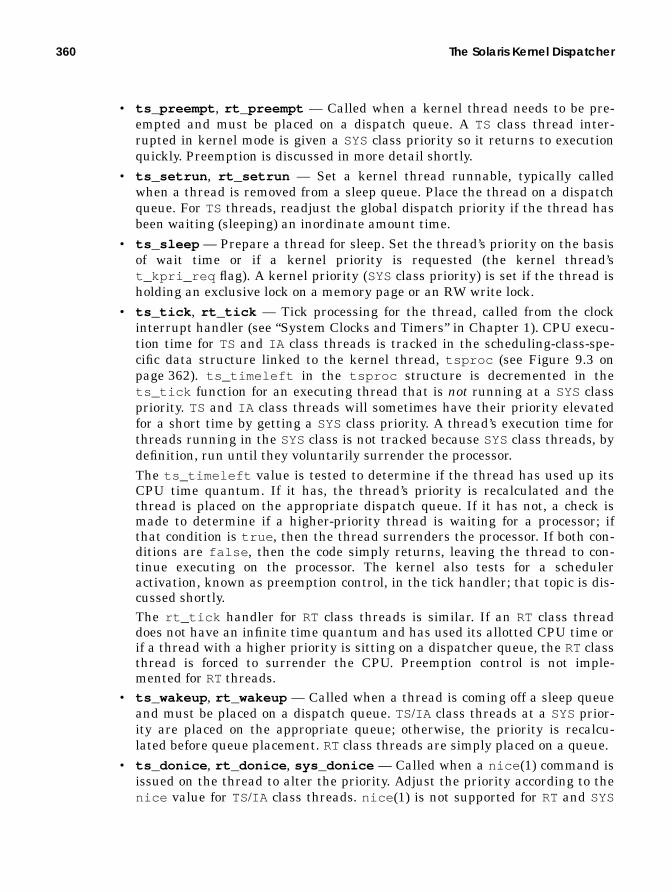
360 The Solaris Kernel Dispatcher
• ts_preempt , rt_preempt — Called when a kernel thread needs to be pre-empted and must be placed on a dispatch queue. A TS class thread inter-rupted in kernel mode is given a SYS class priority so it returns to executionquickly. Preemption is discussed in more detail shortly.
• ts_setrun , rt_setrun — Set a kernel thread runnable, typically calledwhen a thread is removed from a sleep queue. Place the thread on a dispatchqueue. For TS threads, readjust the global dispatch priority if the thread hasbeen waiting (sleeping) an inordinate amount time.
• ts_sleep — Prepare a thread for sleep. Set the thread’s priority on the basisof wait time or if a kernel priority is requested (the kernel thread’st_kpri_req flag). A kernel priority (SYSclass priority) is set if the thread isholding an exclusive lock on a memory page or an RW write lock.
• ts_tick , rt_tick — Tick processing for the thread, called from the clockinterrupt handler (see “System Clocks and Timers” in Chapter 1). CPU execu-tion time for TS and IA class threads is tracked in the scheduling-class-spe-cific data structure linked to the kernel thread, tsproc (see Figure 9.3 onpage 362). ts_timeleft in the tsproc structure is decremented in thets_tick function for an executing thread that is not running at a SYS classpriority. TS and IA class threads will sometimes have their priority elevatedfor a short time by getting a SYS class priority. A thread’s execution time forthreads running in the SYSclass is not tracked because SYSclass threads, bydefinition, run until they voluntarily surrender the processor.The ts_timeleft value is tested to determine if the thread has used up itsCPU time quantum. If it has, the thread’s priority is recalculated and thethread is placed on the appropriate dispatch queue. If it has not, a check ismade to determine if a higher-priority thread is waiting for a processor; ifthat condition is true , then the thread surrenders the processor. If both con-ditions are false , then the code simply returns, leaving the thread to con-tinue executing on the processor. The kernel also tests for a scheduleractivation, known as preemption control, in the tick handler; that topic is dis-cussed shortly.The rt_tick handler for RT class threads is similar. If an RT class threaddoes not have an infinite time quantum and has used its allotted CPU time orif a thread with a higher priority is sitting on a dispatcher queue, the RT classthread is forced to surrender the CPU. Preemption control is not imple-mented for RT threads.
• ts_wakeup , rt_wakeup — Called when a thread is coming off a sleep queueand must be placed on a dispatch queue. TS/IA class threads at a SYS prior-ity are placed on the appropriate queue; otherwise, the priority is recalcu-lated before queue placement. RT class threads are simply placed on a queue.
• ts_donice , rt_donice , sys_donice — Called when a nice (1) command isissued on the thread to alter the priority. Adjust the priority according to thenice value for TS/IA class threads. nice (1) is not supported for RT and SYS

Overview 361
class threads; the kernel functions for SYS and RT return an invalid opera-tion error. The nice (1) command exists in Solaris for compatibility. Threadpriority adjustments should be done with priocntl (1).
• ts_globpri , rt_globpri — Return the global dispatch priority that athread would be assigned, for a given user mode priority. The calculation ofthe actual dispatch priority of a thread is based on several factors, includingthe notion of a user priority. See “Thread Priorities” on page 375 for details.
• ia_set_process_group — Establish the process group associated with thewindow session for IA class threads.
• ts_yield , rt_yield — Called from the yield (2) system call when a threadis yielding (surrendering) the processor. The kernel thread is placed at theback of a dispatch queue.
The scheduling-class-related structures are depicted in Figure 9.3. The systemclass array is shown, with pointers to the class operations vector array, the classname, and class-specific init routine. Also shown is a coarse-grained view of thesystemwide linked list of kernel threads, each of which is linked to its ownclass-specific data structure. That structure maintains bits of information used bythe dispatcher to manage the execution time and scheduling of the kthread; thestructure also maintains a pointer to the class operations array.
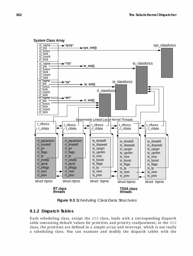
362 The Solaris Kernel Dispatcher
Figure 9.3 Scheduling Class Data Structures
9.1.2 Dispatch Tables
Each scheduling class, except the SYS class, loads with a corresponding dispatchtable containing default values for priorities and priority readjustment; in the SYSclass, the priorities are defined in a simple array and interrupt, which is not reallya scheduling class. You can examine and modify the dispatch tables with the
ts_timeleftts_dispwaitts_cpuprits_uprilimts_nicets_boostts_flagsts_tpts_nextts_prev
t_cldata t_cldata t_cldata t_cldatat_cldata
struct tsproc
ts_timeleftts_dispwaitts_cpuprits_uprilimts_nicets_boostts_flagsts_tpts_nextts_prev
struct tsproc
ts_timeleftts_dispwaitts_cpuprits_uprilimts_nicets_boostts_flagsts_tpts_nextts_prev
struct tsproc
System Class Arraycl_namecl_initcl_funcscl_lockcl_countcl_sizecl_namecl_initcl_funcscl_lockcl_countcl_size
cl_namecl_initcl_funcscl_lockcl_countcl_size
cl_namecl_initcl_funcscl_lockcl_countcl_size
t_clfuncs t_clfuncs t_clfuncs t_clfuncs t_clfuncs
“SYS”sys_init()
“TS”ts_init()
“IA”ia_init()
“RT”rt_init()
ts_classfuncs
ia_classfuncs
rt_classfuncs
rt_pquantumrt_timeleftrt_prirt_flagsrt_tprt_pstatprt_ppriprt_pflagprt_nextrt_prev
struct rtproc
rt_pquantumrt_timeleftrt_prirt_flagsrt_tprt_pstatprt_ppriprt_pflagprt_nextrt_prev
struct rtproc
Systemwide Linked List of Kernel Threads
RT classthreads
TS/IA classthreads
sys_classfuncs

Overview 363
disp_admin (1M) command, for example, dispadmin -c TS -g will dump thecurrent timeshare (TS) and interactive (IA ) class dispatch table on your Solarissystem. (TS and IA use the same dispatch table.)
Table 9-2 shows the default values for a selected group of timeshare/interactivepriorities. In the interest of space and readability, we don’t list all 60 (0–59) priori-ties since we only need a representative sample for this discussion.
# dispadmin -g -c TS# Time Sharing Dispatcher ConfigurationRES=1000
# ts_quantum ts_tqexp ts_slpret ts_maxwait ts_lwait PRIORITY LEVEL 200 0 50 0 50 # 0 200 0 50 0 50 # 1
...........................................................
40 48 58 0 59 # 58 20 49 59 32000 59 # 59
Table 9-2 Timeshare and Interactive Dispatch Table
RES ts_globpri ts_quantum ts_tqexp ts_slpret ts_maxwait ts_lwait PRI
1000 0 200 0 50 0 50 05 200 0 50 0 50 510 160 0 51 0 51 1011 160 1 51 0 51 1115 160 5 51 0 51 1520 120 10 52 0 52 2025 120 15 52 0 52 2530 80 20 53 0 53 3035 80 25 54 0 54 3540 40 30 55 0 55 4045 40 35 56 0 56 4550 40 40 58 0 59 5055 40 45 58 0 59 5559 20 49 59 32000 59 59

364 The Solaris Kernel Dispatcher
Each entry in the TS/IA dispatch table (each row) is defined by the tsdpent (time-share dispatch entry) data structure (from /usr/include/sys/ts.h ), as shownbelow.
The RESand PRI columns are not defined in tsdpent . Those fields, along with thedefined members in the structure table, are described below.
• RES— (resolution value) Interprets the ts_quantum column in the dispatchtable. The reciprocal of RESdetermines the level of granularity in which thets_quantum field will be displayed. As the value of RES increases, thets_quantum column values also increase by the same order of magnitude.See ts_quantum below for more information.
• PRI — The class-dependent priority, not the systemwide global priority. ThePRI column is derived as the row number in the dispatch table. The dispatchtable is like any other generic table—it has rows and columns. Every row cor-responds to a unique priority level within the scheduling class, and each col-umn in the row contains values that determine the priority adjustmentsmade on the thread running at that particular priority. This is not the sameas ts_globpri .
• ts_globpri — The only table parameter (tsdpent structure member) thatis not displayed in the output of the dispadmin (1M) command and also theonly value that is not tunable. ts_globpri is the class-independent globalpriority that corresponds to the timeshare priority (column farthest to theright).A given scheduling class within Solaris has a range of priorities beginningwith 0, which represents the lowest priority for that class. The TS and IAclasses have 60 priorities, range 0–59. The kernel implements a global prior-ity scheme, such that every priority level available in every scheduling classcan be uniquely identified with an integer value. Refer to Figure 9.2 onpage 354 for a list of global priorities when all the bundled scheduling classesare loaded.Since TS/IA is the lowest class, the kernel global priorities 0–59 correspond tothe TS/IA class priorities 0–59. The kernel computes global priorities at boot
* time-sharing dispatcher parameter table entry */typedef struct tsdpent { pri_t ts_globpri; /* global (class independent) priority */ int ts_quantum; /* time quantum given to procs at this level */ pri_t ts_tqexp; /* ts_umdpri assigned when proc at this level */ /* exceeds its time quantum */ pri_t ts_slpret; /* ts_umdpri assigned when proc at this level */ /* returns to user mode after sleeping */ short ts_maxwait; /* bumped to ts_lwait if more than ts_maxwait */ /* secs elapse before receiving full quantum */ short ts_lwait; /* ts_umdpri assigned if ts_dispwait exceeds */ /* ts_maxwait */} tsdpent_t;
Header File <sys/ts.h>

Overview 365
time and will recompute if necessary if a new class is loaded into a runningsystem. For example, referring again to Figure 9.2, if the RT class is notloaded, global priorities for interrupt threads will be 100–109, just above sys-tem (SYS). If the RT class gets loaded, the global priorities for RT become 100–159, and interrupts are bumped up to 160–169. ts_globpri sets the t_prifield for a timeshare kernel thread when priorities are set and readjusted.
• ts_quantum — The time quantum; the amount of time that a thread at thispriority is allowed to run before it must relinquish the processor. Be awarethat the ts_dptbl (4) manual page, as well as other references, indicate thatthe value in the ts_quantum field is in ticks. A tick is a unit of time that canvary from platform to platform. On all UltraSPARC based systems, there are100 ticks per second, so a tick occurs every 10 milliseconds. The value ints_quantum is in ticks only if RES is 100. If RES is any other value, includ-ing the default value of 1000, then ts_quantum represents some fraction of asecond, the fractional value determined by the reciprocal value of RES. With adefault value of RES = 1000, the reciprocal of 1000 is.001, or milliseconds.Thus, by default, the ts_quantum field represents the time quantum for agiven priority in milliseconds.From Table 9-2 on page 363, we see that priority 0 kthreads get 200 millisec-onds (20 ticks), priority 10 kthreads get 160 milliseconds, etc. As a kthread’spriority gets better (higher global priority integer value), its time quantum isless. Lower (worse) priorities get larger time quantums, since they are sched-uled to run less frequently. Changing the RESvalue by using the -r flag withdispadmin (1M)dispadmin -c TS -g -r 100
causes the values in the ts_quantum column to change. For example, at pri-ority 0, instead of a quantum of 200 with a RESof 1000, we have a quantumof 20 with a RESof 100. The fractional unit is different. Instead of 200 milli-seconds with a RESvalue of 1000, we get 20 tenths-of-a-second, which is thesame amount of time, just represented differently [20 ×.010 = 200 ×.001]. Ingeneral, it makes sense to simply leave the RESvalue at the default of 1000,which makes it easy to interpret the ts_quantum field as milliseconds.
• ts_tqexp — Time quantum expired. The new priority a thread is set towhen it has exceeded its time quantum. From the default values in the TSdispatch table, threads at priorities 0–10 will have their priority set to 0 ifthey burn through their allotted time quantum of 200 milliseconds (160 milli-seconds for priority 10 threads). As another example, threads at priority 50have a 40 millisecond time quantum and will have their priority set to 40 ifthey use up their time.
• ts_slpret — The sleep return priority value. A thread that has been sleep-ing has its priority set to this value when it is woken up. These are set suchthat the thread will be placed at a higher priority (in some cases, substan-tially higher) so the thread gets some processor time after having slept(waited for an event, which typically is a disk or network I/O).

366 The Solaris Kernel Dispatcher
• ts_maxwait — Used in conjunction with ts_lwait . They attempt to com-pensate threads that have been preempted and have waited a (relatively)long time before using up their time quantum. When a thread begins execu-tion, a field, called ts_dispwait , in the class-specific structure linked to thethread (Figure 9.3 on page 362) counts the number of seconds that haveelapsed since the thread began executing. This value is not reset if the threadis preempted (must involuntarily relinquish the processor). Once a second, akernel routine executes to increment the ts_dispwait field for all TS and IAclass threads. If the value of the ts_dispwait for the thread is greater thanthat of ts_maxwait , the thread priority is set to the value of ts_lwait , ahigher priority for the thread since in this circumstance it must have beenpreempted and never had a chance to use its time quantum.
• ts_lwait — The new priority for a thread that has waited longer thants_maxwait to use its time quantum. Interesting to note is that the defaultvalues in the TS and IA dispatch tables inject a 0 value in ts_maxwait forevery priority except the highest priority (59). So, just one increment in thets_dispwait field will cause the thread priority to be readjusted tots_lwait , except for priority 59 threads. The net effect is that all but thehighest-priority (59) timeshare threads have their priority bumped to the 50–59 range (ts_lwait ) every second.This process has the desirable effect of not penalizing a thread that isCPU-bound for an extended period of time. Threads that are CPU hogs will,over time, end up in the low 0–9 priority range as they keep using up theirtime quantum because of priority readjustments by ts_tqexp . Once a sec-ond, they’ll get bumped back up to the 50–59 range and will only migrateback down if they sustain their cpu-bound behavior.Priority 59 threads are handled differently. These threads are already at themaximum (highest/best) priority for a timeshare thread, so there’s no way tobump their priority with ts_maxwait and make it better. The ts_update()routine, which is the kernel code segment that increments the ts_dispwaitvalue and readjusts thread priorities by means of ts_lwait , reorders thelinked list of threads on the dispatch queues after adjusting the priority. Thereordering after the priority adjustment puts threads at the front of their newdispatch queue for that priority. The threads on the priority 59 linked listwould end up reordered but still at the same priority.Experimentation has shown that this approach has two results: some per-centage of priority 59 threads never get processor time, and the threads thatts_update() puts on the front of the dispatch queue following adjustmentget scheduled more frequently. When the ts_maxwait value is set to 32000for priority 59, the queue is never reordered by ts_update() and everythread has a fair shot at getting scheduled.
You can apply user-supplied values to the dispatch tables by using the dispad-min (1M) command or by compiling a new /kernel/sched/TS_DPTBL loadablemodule and replacing the default module. The ts_dptbl (4) manual page providesthe source and the instructions for doing this. Either way, any changes to the dis-

Overview 367
patch tables should be done with extreme caution and should be tested exten-sively before going into production—we’ve seen dispatch table “tweaks” drasticallyaffect the performance of a system, not always for the better.
The interactive class (IA ) uses the timeshare dispatch table. This is not neces-sarily intuitive; you can specify the TS or IA table to the dispadmin (1M) com-mand, and the command output header will indicate either “Interactive DispatcherConfiguration” or “Time Sharing Dispatcher Configuration,” depending on whatwas specified on the command line. Both classes use the same dispatch table; thus,any changes made for one class affects the other. The IA class was added to makethe Solaris window-based desktop environment provide snappier performance. Toenhance performance, all processes that started under the windowing system(either OpenWindows or CDE) are put in the IA class, and the priority of pro-cesses attached to the window that has the current input focus (the active win-dow—the one being used by the user) is boosted. The procedure uses most of theTS class infrastructure with just a few IA -specific routines, which we discuss in thenext section.
For the SYS class (kernel mode priorities), an array is built within the TS classframework to define the kernel mode priorities available to TS/IA class threadswhen they warrant a priority boost into the SYS class. Theconfig_ts_kmdpris[] array is an array of 40 priorities, values 60–99, and isdefined in the tsdptbl (timeshare dispatch table) loadable module that can bemodified, compiled, and loaded into the system. (See ts_dptbl (4) for instructionsand the module template.) The array is referenced through a ts_kmdpris pointerthat points to the first element in the array.
The realtime (RT) dispatch table is quite simple, since RT threads run at fixed pri-orities. The kernel does not change the priority of an RT thread unless explicitlyinstructed to do so as a result of a priocntl (1) command or priocntl (2) system
/* Array of global priorities used by ts procs sleeping or * running in kernel mode after sleep. Must have at least * 40 values. */
pri_t config_ts_kmdpris[] = { 60,61,62,63,64,65,66,67,68,69, 70,71,72,73,74,75,76,77,78,79, 80,81,82,83,84,85,86,87,88,89, 90,91,92,93,94,95,96,97,98,99};

368 The Solaris Kernel Dispatcher
call. Each entry in the RT dispatch table is defined by the rtdpent data structurein /usr/include/sys/rt.h .
The RT dispatch table contains two columns: the rt_quantum field, which is thetime quantum for processor execution time, and rt_globpri , which is the system-wide global priority, calculated dynamically when the RT scheduling class isloaded. The rt_quantum field has the same meaning as the ts_quantum field inthe TS table, that is, the amount of time a thread at this priority is allowed to runbefore being scheduled off the processor. Also, just as with the TS table, when thedispatch table is dumped by means of the dispadmin (1M) command, the value isdependent on the RESvalue. With a default RESvalue of 1000, rt_quantum is inmilliseconds. Also as with the TS table, the PRIORITY column produced by dis-padmin (1M) equates to the row number of the dispatch table entry, which is thesame as the class-specific priority level and is not the same as rt_globpri , theglobal priority.
9.2 The Kernel Dispatcher
The dispatcher is the kernel code segment that manages queues of runnable ker-nel threads, called dispatch queues, places the highest-priority runnable thread ona processor for execution, and manages the recalculation of thread priorities thatare based on execution time, sleep time, and time spent on the queue waiting for aprocessor. The context switching of threads on and off processors is driven by thedispatcher code.
* Real-time dispatcher parameter table entry */typedef struct rtdpent { pri_t rt_globpri; /* global (class independent) priority */ int rt_quantum; /* default quantum associated with this level */} rtdpent_t;
Header File <sys/rt.h>
# dispadmin -g -c RT# Real Time Dispatcher ConfigurationRES=1000
# TIME QUANTUM PRIORITY# (rt_quantum) LEVEL 1000 # 0 1000 # 1
...............................
100 # 58 100 # 59
The Kernel Dispatcher 369
Early versions of Solaris 2 implemented a simple, global dispatch queue thatwas shared by all processors on a multiprocessor system. Scalability and dispatchlatency, especially for real-time threads, was less than optimal because of thecoarse-grained locking. A single scheduling lock for the dispatch queue needed tobe acquired for a processor to insert or remove a kthread from the queue, whichbecame a point of contention on busy multiprocessor systems. A new design wasdone for Solaris 2.3, and since that release, Solaris implements multiple dispatchqueues, one for each processor, and a global queue for threads that run at a prior-ity high enough to cause kernel preemption. Such threads are real-time and inter-rupt threads (although interrupt threads are not placed on a dispatch queue—theylive on a linked list off every CPU structure). Solaris 2.5 saw an algorithmicchange to the thread selection process (which thread gets execution time next). Wego through the select and ratify process of thread selection in our discussion of thedispatcher algorithm.
Another change came with the introduction of processor sets in Solaris 2.6. Pro-cessor sets can be configured through psrset (1M), where some number of proces-sors are configured into the set, and processes and kernel threads can be bound toa processor set. The bound processes and threads are scheduled only on processorsin the set; other threads and processes running on the system that are not boundto the processor set will not be scheduled on processors in the set. Multiple proces-sor sets can be configured, with multiple bindings. (Processor sets are also dis-cussed in Chapter 1, “System Overview.”) The addition of processor sets added anew data structure, cpupart , and a modification to the kernel preempt dispatchqueues. Prior to Solaris 2.6, only one kernel preempt queue maintained runnableRT class threads. Beginning in Solaris 2.6, there is a kernel preempt queue foreach processor set or one queue systemwide if processor sets have not been config-ured.
The dispatcher uses data stored in different areas of the kernel to maintainscheduling information such as priorities, thread execution time, dispatch queueutilization and state, thread wait and sleep time, per-processor queue data andstate, etc. The dispatch tables described in the previous section are just one area ofthe kernel where scheduling-specific information is stored. In addition to thetables, a scheduling-class-specific data structure is linked to every kthread on thesystem. These structures, illustrated in Figure 9.3 on page 362, are used by thedispatcher for maintaining bits of information on each thread’s execution time,state, and priority.
The class-specific data structures are linked not only to the kthread but also toeach other. That is, the class-specific structures are linked on a linked list main-tained by the dispatcher code. Many of the fields in the class-specific structureshave the same name and meaning across all three scheduling classes (TS, IA , andRT; there is no structure for the SYS class). Hence, we describe each structure inTable 9-3 by using a single row where a structure member has a common nameand meaning for more than one scheduling class. The structures take the name ofxxproc, where xx is ts, rt, or ia.

370 The Solaris Kernel Dispatcher
As we mentioned earlier, the kernel maintains doubly linked lists of the class-spe-cific structures—separate lists for each class. Current implementations of Solaris,up to and including Solaris 7, do not actually use the iaproc for interactive classthreads (it’s declared in the sys/ia.h header file but not defined anywhere in thekernel code). Threads in the IA class link to a tsproc structure, and most of theclass supporting code for interactive threads is handled by the TS routines. IAthreads are distinguished from TS threads by a flag in the ts_flags field, theTSIA flag.
Maintaining the linked lists for the class structures greatly simplifies the dis-patcher supporting code that updates different fields in the structures (such astime quantum) during the clock-driven dispatcher code. Since most Solaris sys-tems have considerably more TS threads than any other scheduling class, thetsproc lists are managed differently from the RT list.
The kernel builds an array of 16 tsproc structures (array namets_plisthead ) that anchor up to 16 doubly linked lists of the tsproc structuressystemwide. The code implements a hash function, based on the thread pointer, todetermine which list to place a thread on, and each list is protected by its own ker-nel mutex (ts_list_lock is an array of 16 kernel mutexes). Implementing multi-ple linked lists in this way makes for faster traversal of all the tsproc structures
Table 9-3 Scheduling-Class-Specific Data Structure Members
tsproc iaproc rtproc Meaningts_timeleft ia_timeleft rt_timeleft Time remaining in thread’s time
quantumts_dispwait ia_dispwait N/A Wall clock elapsed time since
quantum began. Not reset ifthread is preempted
ts_cpupri ia_cpupri N/A Priorityts_uprilim ia_uprilim N/A User priority limitts_upri ia_upri N/A User priorityts_umdpri ia_umdpri N/A User priority within classts_nice ia_nice N/A Nice valueN/A N/A rt_pquantum Time quantum for the threadN/A N/A rt_pri Priority within RT classts_flags ia_flags rt_flags State flagsts_boost N/A N/A Priority boost valueN/A ia_pstatp rt_pstatp Pointer to pstat
N/A ia_pprip rt_pprip Pointer to thread priorityN/A ia_pflagp rt_pflagp Pointer to p_flag
N/A ia_mode N/A IA on/off flagts_tp ia_tp rt_tp Pointer back to kthreadts_next ia_next rt_next Forward linkts_prev ia_prev rt_prev Backward link

The Kernel Dispatcher 371
in a running system, and the use of a lock per list allows multiple kernel routinesto traverse different lists at the same time (see Figure 9.4).
Figure 9.4 tsproc Structure Lists
9.2.1 Dispatch Queues
Every processor on the system has its own dispatch queue (actually, a queue ofqueues), and per-processor scheduling information is maintained in the data struc-tures that describe the processors in the kernel (the CPU structures). Data struc-tures make up the actual dispatch queues, which provide the linkage to the lists ofrunnable kthreads on the system and state information for each queue. Threads inthe TS, IA , and SYS classes are placed on the per-processor dispatch queues.
A separate queue is maintained for threads that are runnable at a priority highenough to cause a kernel preemption. The Solaris kernel is, for the most part, pre-emptable, such that a processor executing in kernel (system) mode can be pre-empted so a higher-priority thread can run. Currently, the global dispatchpriorities for RT class threads and interrupt threads are above SYSand can gener-ate a kernel preemption. Since interrupt threads do not actually go on a dispatchqueue, only unbound RT class threads are placed on the kernel preempt(kp_preempt ) queue. There is one such queue systemwide on systems that do nothave processor sets configured. A kernel preempt queue is created when a proces-sor set is configured, so there is a per-processor set kp_preempt queue, plus onefor the default processor set. Since the kernel will not allow every available proces-sor on a system to be placed in a processor set, the number of kernel preemptqueues on a system will always be the number of processor sets configured, plus 1.Without processor sets configured, there is one kp_preempt queue systemwide.We discuss preemption later in more detail.
The creation of the dispatch queues occurs at boot time during the Solaris sys-tem initialization. A kernel dispatcher initialization routine, dispinit() , iscalled from the architecture-specific startup code, which builds the kernel preemp-tion queue and the per-cpu dispatch queues. The kernel data structures that makeup the complete dispatch queue picture are the cpu , disp_queue_info , _disp ,and dispq structures, as shown in Figure 9.5 on page 374. It is during the dis-patcher initialization that the default processor partition is created, which iswhere the kernel preempt queue (cp_kp_queue ) is maintained. In Solaris 2.5.1,
mutexmutexmutex
tsproctsproctsproc
ts_plistheadts_list_locktsproc tsproc
tsproc tsproc tsproctsproc tsproc tsproc

372 The Solaris Kernel Dispatcher
which does not have processor sets, the global kernel preempt queue was main-tained in a separate disp_t structure, disp_kp_queue .
A quick note on terminology before we proceed. A processor partition is essen-tially the same thing as a processor set. A user’s view of a processor set is what thekernel references as a processor partition. A different abstraction exists for a pos-sible future implementation, where some processor partitions are visible to thekernel but not visible to the user, so what users see as available processor sets maybe different from the kernel’s view of usable processor partitions. A default proces-sor partition, which includes all available processors on the system, is created atboot time. As processor sets are created, processors configured into a user proces-sor set are removed from the default partition and added to the configured set.(Processor sets are discussed in “Kernel Processor Control and Processor Sets” onpage 419.)
The kernel retains at least one processor for the default partition and does notallow all available processors to be configured into user-created processor sets.Kernel threads that are part of the operating system, such as the daemon threadscreated at boot time (Chapter 2), pageout, NFS server threads, etc., will not run ona user processor set. That’s why a default partition is created at boot time and atleast one processor is retained for the default partition. In practice, it is alwaysprudent to assess processor requirements before allocating processor resources bymeans of processor sets. A system with sufficient processing power for bound appli-cation processes may run poorly if CPU resources for the kernel are inadequate.
Several dispatcher-related variables are embedded in each cpu structure.
• cpu_disp — An embedded _disp structure; the dispatch queue data for theprocessor, which contains the link to the actual per-processor queues.
• cpu_runrun — A preemption flag indicating that the thread currently run-ning on the CPU will be preempted before switching back to user mode. Theuser preemption flag.
• cpu_kprunrun — Another preemption flag, kernel preemption, indicatingthat the thread should be preempted immediately or as soon as possible (e.g.,return from an interrupt). The kernel preemption flag.
• cpu_chosen_level — The priority at which the CPU was chosen for sched-uling a kthread. Used by the dispatcher when selecting the next thread forexecution.
• cpu_dispthread — A pointer to the kthread selected for execution on theCPU.
• cpu_thread_lock — A dispatcher lock on the current thread.• cpu_last_switch — A time value: the last time the CPU switched execu-
tion to a new thread.
The dispatcher queue structure embedded in the cpu structure is where theper-CPU dispatch queue is rooted. It links to the per-priority dispatch queues

The Kernel Dispatcher 373
maintained for each processor. Within each processor dispatch queue, separatelinked lists of runnable kthreads are maintained for every priority level, exceptrealtime lists. Unbound realtime threads are maintained on the global kp_queue .If processor sets are configured, then a kernel preempt queue is configured for eachprocessor set.
Other data the dispatcher needs for queue management and thread schedulingmaintained in the dispatch queue structure includes the following.
• disp_lock — A synchronization lock to protect fields in the structure.• disp_npri — The number of priority levels in the queue.• disp_q — The pointer to the dispatch queue (pointer to a dispq_t struc-
ture).• disp_q_limit — Another pointer to a dispq_t structure, set to point to the
end of the queue.• disp_qactmap — A bitmap indicating which queues actually have runnable
threads in them. Using the bitmap in conjunction with disp_maxrunpri anddisp_nrunnable , the dispatcher code can traverse the queues with extremespeed and efficiency, searching for the best runnable thread.
• disp_maxrunpri — The priority of the highest-priority thread on the queue.• disp_max_unbound_pri — The priority of the highest-priority unbound
thread on the queue.• disp_nrunnable — Total number of runnable threads on the queue.• disp_cpu — A pointer back to the cpu structure that owns this queue.
The dispatch queue entry itself is a small, three-member data structure, defined asa dispq_t structure. It contains a pointer to the first kthread on the queue(dq_first ), a pointer to the last kthread on the queue (dq_last ), and a count ofkthreads on the queue (dq_sruncnt ). Each per-priority queue maintains a countof threads on the queue, and the sum of all per-priority queues is represented indisp_nrunnable .
Finally, there’s the disp_queue_info structure. An array of these structures iscreated at boot time, one for each processor on the system. Each array member(disp_queue_info structure) contains a pointer to one per-process dispatchqueue (disp_t ) embedded in the cpu structure. There are two additional disp_tpointers, olddispq and newdispq , and storage space for an old and new queuebitmap field, oldqactmap and newqactmap , for queue manipulation and mainte-nance. The number of global priorities in the queue is also maintained in old-nglobpris . As we move through the algorithmic flow of the dispatcher code, we’llsee how these structures and members are used. Figure 9.5 provides the big pic-ture.

374 The Solaris Kernel Dispatcher
Figure 9.5 Solaris Dispatch Queues
disp_memAr
ray
of d
isp_
queu
e_in
fo s
truct
ures
,1
per p
roce
ssor
.*dp*olddispq*newdispq*olddqactmap*newdqactmapoldnglobpris
*dp*olddispq*newdispq*olddqactmap*newdqactmapoldnglobpris
*dp*olddispq*newdispq*olddqactmap*newdqactmapoldnglobpris
cpu_runruncpu_kprunruncpu_chosen_levelcpu_dispthreadcpu_thread_lockcpu_last_switch
disp_lockdisp_npridisp_qdisp_q_limitdisp_qactmapdisp_maxrunpridisp_max_unbound_pridisp_nrunnabledisp_cpu
cpu_nextcpu_prev
cpu_runruncpu_kprunruncpu_chosen_levelcpu_dispthreadcpu_thread_lockcpu_last_switch
disp_lockdisp_npridisp_qdisp_q_limitdisp_qactmapdisp_maxrunpridisp_max_unbound_pridisp_nrunnabledisp_cpu
cpu_nextcpu_prev dq_first
dq_lastdq_sruncnt
dq_firstdq_lastdq_sruncnt
dq_firstdq_lastdq_sruncnt
dq_firstdq_lastdq_sruncnt
dq_firstdq_lastdq_sruncnt
dq_firstdq_lastdq_sruncnt
cpu structures
kthread
kthread
kthread
kthread
kthread
Arra
y of
dis
patc
her q
ueue
s, 1
for e
ach
prio
rity
leve
lLinked listsof kthreads,1 list for eachpriority. TS, IA,
Dispatch queuefor another CPU
cpu_part
cpu_part
disp_lockdisp_npridisp_qdisp_q_limitdisp_qactmapdisp_maxrunpridisp_max_unbound_pridisp_nrunnabledisp_cpu
cpupart structure
cp_k
p_qu
eue
cp_idcp_ncpus...
dq_firstdq_lastdq_sruncntdq_firstdq_lastdq_sruncntdq_firstdq_lastdq_sruncnt
kthread kthread
kthread
Kernel Preempt Queue
Per-processor queues
RT classrunnablethreads
and SYS class
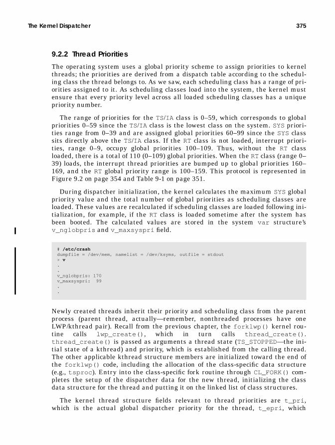
The Kernel Dispatcher 375
9.2.2 Thread Priorities
The operating system uses a global priority scheme to assign priorities to kernelthreads; the priorities are derived from a dispatch table according to the schedul-ing class the thread belongs to. As we saw, each scheduling class has a range of pri-orities assigned to it. As scheduling classes load into the system, the kernel mustensure that every priority level across all loaded scheduling classes has a uniquepriority number.
The range of priorities for the TS/IA class is 0–59, which corresponds to globalpriorities 0–59 since the TS/IA class is the lowest class on the system. SYS priori-ties range from 0–39 and are assigned global priorities 60–99 since the SYS classsits directly above the TS/IA class. If the RT class is not loaded, interrupt priori-ties, range 0–9, occupy global priorities 100–109. Thus, without the RT classloaded, there is a total of 110 (0–109) global priorities. When the RT class (range 0–39) loads, the interrupt thread priorities are bumped up to global priorities 160–169, and the RT global priority range is 100–159. This protocol is represented inFigure 9.2 on page 354 and Table 9-1 on page 351.
During dispatcher initialization, the kernel calculates the maximum SYSglobalpriority value and the total number of global priorities as scheduling classes areloaded. These values are recalculated if scheduling classes are loaded following ini-tialization, for example, if the RT class is loaded sometime after the system hasbeen booted. The calculated values are stored in the system var structure’sv_nglobpris and v_maxsyspri field.
Newly created threads inherit their priority and scheduling class from the parentprocess (parent thread, actually—remember, nonthreaded processes have oneLWP/kthread pair). Recall from the previous chapter, the forklwp() kernel rou-tine calls lwp_create() , which in turn calls thread_create() .thread_create() is passed as arguments a thread state (TS_STOPPED—the ini-tial state of a kthread) and priority, which is established from the calling thread.The other applicable kthread structure members are initialized toward the end ofthe forklwp() code, including the allocation of the class-specific data structure(e.g., tsproc ). Entry into the class-specific fork routine through CL_FORK() com-pletes the setup of the dispatcher data for the new thread, initializing the classdata structure for the thread and putting it on the linked list of class structures.
The kernel thread structure fields relevant to thread priorities are t_pri ,which is the actual global dispatcher priority for the thread, t_epri , which
# /etc/crashdumpfile = /dev/mem, namelist = /dev/ksyms, outfile = stdout> v..v_nglobpris: 170v_maxsyspri: 99..

376 The Solaris Kernel Dispatcher
reflects an inherited priority, and t_kpri_req , which is a flag to indicate to thedispatcher that a SYSpriority is requested for the thread. Other per-thread prior-ity-related data is maintained in the class-specific data structure linked to thekthread: tsproc for TS/IA threads, rtproc for RT threads. For TS/IA threads, thekernel provides a facility for user-level priority adjustments, similar in concept tothe traditional nice (1) command. Unix systems provided a nice (1) command thatallowed users to adjust the priority of the processes they owned. Non-root userscould only make their own process priorities worse (they could be nice to the otherusers of the system), and root could make priorities better with nice (1). Solarissupports nice (1) today for compatibility, but the proper way to apply user-levelpriorities to threads is to use the priocntl (1) command. Issuing priocntl (1)with the -l (lowercase l) flag displays the range of user priorities.
The user priority ranges shown in the preceding priocntl (1) command outputclearly do not reflect the range of priorities for the TS/IA class from a kernel per-spective. The user priority facility allows a user to move a process or thread prior-ity in a positive (better) or negative (worse) direction. The priority value specifiedon the command line can be as high as 60 (maximum potential priority) or as lowas −60 (lowest possible priority). A priority value specified on a priocntl (1) com-mand line does not become the process’s or thread’s actual global dispatch priority(as seen with ps (1), e.g., ps -Lc ), but rather is used by the dispatcher code toadjust a kernel thread’s priority. A user-supplied priority will alter the global dis-patcher priority of the thread in one direction or another, depending on the valuespecified.
For RT class threads or processes, the valid range of priorities is 0–59; the pri-ocntl (1) output shown above indicates a maximum value of 59. The RT class doesnot support the notion of user mode priorities. Priority tweaking of RT threadsinvolves simply specifying a priority value in the RT class range; then, that valuewill be directly reflected in the global dispatch priority of the process. For exam-ple, the global priority range for RT is 100–159, where global priority 100 corre-sponds to RT priority 0, global priority 120 corresponds to RT priority 19, and so on.
# priocntl -lCONFIGURED CLASSES==================
SYS (System Class)
TS (Time Sharing) Configured TS User Priority Range: -60 through 60
IA (Interactive) Configured IA User Priority Range: -60 through 60
RT (Real Time) Maximum Configured RT Priority: 59

The Kernel Dispatcher 377
So, below, we used priocntl (1) to start a program in real time and specified a pri-ority.
We specified a priority value of 59 on the command line. Note the actual global dis-patch priority of the process we started is 159. This value results from the kernelturning the specified priority into a global dispatch priority. In the case of RT pro-cesses and threads, the kernel uses the user-supplied RT priority value as an indexinto the RT dispatch table to retrieve the corresponding global dispatch priority, asillustrated in Figure 9.6.
Figure 9.6 Setting RT Priorities
An invocation of the priocntl (1) command to execute a process as a real-timeprocess defaults to the base RT class priority, which is 0, resulting in a global dis-patch priority of 100—the value in the 0th entry in the real-time dispatch table(rt_dptbl ). The example in Figure 9.6 specifies a value of 59, which the kernelwill plug into the rt_pri field of the thread’s rtproc structure and use as anindex in the dispatch table, rt_dbtbl . The corresponding value is used to set thethread’s actual global dispatch priority, 159, in this example. A kernelthread_change_pri() function is called to set the dispatcher priority in thekthread’s t_pri field.
User-settable priorities for RT threads is the easy case, which is why we talkedabout that first. The SYS class is even easier: user-level tweaking of SYS classthread priorities does not exist, period. Which brings us back to TS/IA classthreads. First, a quick note before we move on. Kernel threads in the same pro-cess can run at different scheduling classes and priorities. A multithreaded pro-cess can have LWP/kthread pairs in the TS, IA , SYS, and RT class. The
# priocntl -e -c RT -p 59 ./hog &1016# ps -Lc PID LWP CLS PRI TTY LTIME CMD 1016 1 RT 159 pts/2 0:03 hog 1015 1 TS 48 pts/2 0:00 sh 1017 1 TS 48 pts/2 0:00 ps
100101102103104105
rt_dptbl#priocntl -e -c RT -p 59 program
proc
kthr
ead/
LWP
rtproc
rt_pri
t_pri
time
quan
tum
s
159

378 The Solaris Kernel Dispatcher
priocntl (1) command, however, does not provide that level of granularity for con-trol. priocntl (1) provides for scheduling class and priority control only on aper-process level, not per LWP/kthread. The priocntl (2) system call has facili-ties for specifying an LWP ID versus a PID, so code can alter scheduling classesand priorities at the LWP/kthread level.
Several fields in the tsproc structure support the implementation of user modepriorities for TS threads: ts_umdpri , the user priority within the TS class range;ts_upri , the user priority value; ts_uprilim , a boundary (limit) on user prior-ity values; and ts_cpupri , the kernel component of user priorities. ts_cpupriexists essentially to give the kernel some control over user-adjusted priorities(think of it as a throttle). It is used in conjunction with the user priority,ts_umdpri , to index into the TS dispatch table to set new values for bothts_cpupri and the thread’s actual priority, t_pri . The ts_uprilim field existsto enable users to place their own throttle on user mode priorities.
The dispatcher uses these values in the kernel for boundary checking onuser-supplied priorities and for adjusting a thread’s priority as a result of the pri-ocntl() call. Once user priorities are set, they remain in use for subsequentthread priority adjustments. ts_cpupri is set to 29 when the LWP/kthread is ini-tialized; ts_upri and ts_uprilim are initialized to 0. Without an explicit prio-cntl (1) or priocntl (2) command issued on a process or kthread, the user modepriorities do not factor in to the normal priority adjustments done during the exe-cution life of a kernel thread. If an LWP/kthread has a user priority set and issuesa fork() , then the new process LWP/kthread inherits the user-supplied valuesfrom the parent thread.
RT class thread priorities are fixed, as oppsed to TS/IA thread priorities, whichare adjusted in many places during the life of a thread: after initialization onreturn from a fork() , when a thread is made runnable by ts_setrun() , uponsleep and wakeup, upon return from a trap, during clock tick processing, prior to acontext switch, and during a regular thread update that is executed through thecallout queue feature from the clock interrupt handler. The actual priority adjust-ment is, in some cases, contingent on a conditional test in the code, for example,has a thread been waiting to get on a dispatch queue for an inordinate amount oftime? We’ll look at some examples to illustrate the mechanics of establishing athread’s priority, starting with TS and IA class threads.
Refer to Figure 9.7, which illustrates the following sequence.
1. After the creation and initialization of the LWP/kthread (fork() ), a forkreturn function is called to set the kthread’s priority and place it on a dis-patch queue. The inherited ts_cpupri value indexes into the TS dispatchtable (1).
2. It creates a new ts_cpupri value that is based on the ts_tqexp value inthe indexed table location.
3. The ts_timeleft value is set on the basis of the allotted time quantum forthe priority level.

The Kernel Dispatcher 379
4. ts_dispwait is set to 0. A user mode priority is calculated, setting thets_umdpri value, which is then used as an index into the TS/IA dispatchtable o establish the thread’s actual dispatch priority,
5. t_pri is determined by the ts_globpri (global priority) value in theindexed table location (5).
Figure 9.7 Setting a Thread’s Priority Following fork()
The calculation of the user mode priority (between steps 2 and 3), which is donewhenever a TS/IA thread priority adjustment is required, is simple arithmetic,summing the ts_cpupri , ts_upri , and ts_boost values. ts_boost is used forIA class threads as a means of boosting the priority by a value of 10. ts_umdpri isset to the sum of ts_cpupri , ts_upri , and ts_boost and is tested against someboundary values; it cannot be greater than the maximum TS/IA class priority, 59,or less than 0.
The other relevant step taken in the fork return code is the setting of thets_timeleft and ts_dispwait fields in the kthread’s tsproc structure.ts_timeleft tracks execution time when the kthread is running on a processorand is decremented in the clock tick handler (if the thread is actually running on aprocessor, of course). When ts_timeleft counts down to 0, the kthread has usedits time quantum and is context-switched off the processor. ts_dispwait trackshow much time the thread has spent sitting on a dispatch queue, waiting to getcontext-switched onto a processor for execution. For all threads on a dispatchqueue, ts_dispwait is updated once a second by the ts_update() thread, whichis run out of the callout queue from the clock interrupt handler (more on this in aminute).
When the priority work has been done and t_pri in the kernel thread has avalid dispatch priority, the thread is ready to be placed on a dispatch queue; suchplacement is ultimately done by one of the dispatcher queue management func-tions, setfrontdq() or setbackdq() . How these functions work and whether a
t_pri
ts_cpuprits_umdpri
kthread
tsproc
ts_g
lobp
ri
ts_q
uant
um
ts_t
qexp
ts_s
lpre
t
ts_m
axw
ait
ts_l
wai
t
1
2
3
4
ts_dptbl
ts_timeleftts_dispwait
5
..
.

380 The Solaris Kernel Dispatcher
kthread ends up at the front or back of a queue are matters we’ll get into in just abit.
Once a kthread is off and running, it can go through potentially many statechanges that determine how and where priority adjustments are made. A typicalthread spends time executing, gets interrupted, gets preempted, issues a blockingsystem call causing the thread to be placed on a sleep queue, and so forth.Class-specific functions are called and act appropriately as dictated by the transi-tion and the dispatcher-related values in the thread’s tsproc structure for prior-ity adjustment. For example, if a thread burns through its allotted time quantum(as set from the ts_quantum value in the dispatch table, Figure 9.7, step 3), thekthread is switched off the processor and given a new dispatch priority.
The scheduling-class-specific clock tick handler is called from the system clockinterrupt handler for each CPU that has a noninterrupt thread running on it.When the ts_tick() function is entered, the ts_timeleft value is decrementedand tested. If ts_timeleft reaches 0, the time quantum has expired for thekthread. This is the case for TS/IA threads that are not at a SYS class priority—threads running at a SYS class priority are not time sliced. Assuming an expiredtime quantum, the code tests to see if a scheduler activation has been turned on forthe thread, in the form of preemption control.
Solaris provides an innovative facility, called preemption control, for stretchinga thread’s time quantum for a short time. Preemption control does not requirealtering priorities or dispatcher table values. Using a simple API—schedctl_init (3X), schedctl_start (3X), schedctl_stop (3X)—program-mers can develop code that initializes and turns on a preemption control for akthread. What this does is effectively give the kthread a few extra clock ticks ofexecution time on a processor, beyond its time quantum, before it is switched off.This feature addresses situations where a thread is holding a critical resource,such as a mutex lock (an application-level mutex lock, not a kernel mutex lock)and a few extra ticks of execution time will allow the kthread to complete its taskand free the lock. Otherwise, if the thread is taken off the processor before releas-ing the resource, other threads that need the same resource will begin to block,waiting for the resource to be freed. This behavior requires that the thread hold-ing the resource work its way up the dispatch queue for rescheduling.

The Kernel Dispatcher 381
The use of preemption control in application code is illustrated in the followingpseudocode, showing preemption control being turned on and then off around theacquisition and freeing of a mutex lock.
Without the activation turned on to enable preemption control, there’s a greaterpossibility that the kthread will be forced to surrender the processor before it isable to free the lock. Think of preemption control as a means of telling the dis-patcher “I’m about to grab a critical resource, so grant me a little extra executiontime.”
Getting back to the ts_tick() code, we’ve entered the main processing seg-ment of ts_tick() because the kthread was not running at a SYS class priorityand its time quantum has expired. If preemption control has been turned on forthe kthread, it is allowed an extra couple of clock ticks to execute, no prioritytweaks are done, and ts_tick() is finished with the thread. There is a limit tohow many additional clock ticks a kthread with preemption control turned on willbe given. If that limit has been exceeded, the kernel sets a flag such that thethread will get one more time slice and on the next pass through ts_tick() , thepreemption control test will fail and normal tick processing will be done. In thisway, the kernel does not allow the scheduler activation to keep the thread runningindefinitely. If the requirement is that the thread must stay on the processor indef-initely, the RT class should be used.
Regular TS/IA tick processing involves adjusting the thread priority in the sameway the priority is set in the fork return code (Figure 9.7 on page 379). ts_cpupriis used as an index into the TS dispatch table and is assigned a new value that isbased on ts_tqexp from the indexed location. The user mode priority is calcu-lated, ts_dispwait is set to 0, and a new dispatcher priority is derived from theTS/IA dispatch table. The new priority is based on the global priority value in thetable row corresponding to ts_umdpri , which is used as the dispatch table arrayindex. What’s different between the ts_tick() handler and the fork return sce-nario is that the thread’s priority is not set directly in ts_tick() , but rather in athread_change_pri() kernel function. A change in a thread’s priority may war-rant a change in its position on a queue; thread_change_pri() handles such acase. In the fork return, we are dealing with a new thread that has not yet been ona queue, so it’s not an issue.
mutex_t mylock;mutex_init(&mylock);schedctl_init();..schedctl_start();mutex_lock(&mylock);
do work while holding the mutex
mutex_unlock(&mylock);schedctl_stop();

382 The Solaris Kernel Dispatcher
By design for TS/IA class threads, the adjusted priority in the preceding sce-nario will end up being something worse than the thread had previously. If athread consumed its entire time quantum, it gets a worse priority to allow otherthreads a better opportunity to obtain processor time. You can test this behavior byplugging in some actual values, walking through the adjustment sequence as wedescribed it, and figuring out where the thread’s priority lands after the threaduses a full time quantum.
Here’s a quick example, assuming a simple case of no user mode priority.
• A kthread starts with a ts_cpupri value of 29, which puts its right in themiddle of the TS/IA priority range (which we’re assuming is why the defaultvalue of 29 was chosen). The ts_tqexp value at table location 29 (the 28throw, because the count starts at 0) is 18.
• Thus, the new ts_cpupri value is 18, which also becomes the ts_umdprivalue when the user mode priority is calculated—since ts_upri andts_boost are zero values (no user priority, and it’s a TS class thread, so nopriority boost).
• The global dispatch priority at index location 18 is 17, so the kthread’s initialpriority (t_pri ) is 17, with a 120 clock tick time quantum (derived by usingts_cpupri as an index).
• When 120 ticks are gone and ts_timeleft has clicked down to 0, we’llessentially repeat the steps to get the new priority.
• ts_cpupri is now 18, the ts_tqexp value at the corresponding table loca-tion is 7, so the new ts_cpupri value is 7, which again becomes ts_umdpriafter the user mode priority is calculated.
• The global dispatch priority at the 7th array location is 6, so the kthread’spriority after the kthread uses its time quantum will go from 17 to 6, a worsepriority. Its time quantum is larger, at 160 clock ticks, so it will wait longer torun but will get more clock ticks when it does execute. The behavior is consis-tent with the targeted behavior of timeshare class threads. As threads getmore execution time, their priority is worsened; as threads spend more timewaiting to run, their priority is improved.
The second case we’ll look at centers around kthread sleep and wakeup. Specificsof the sleep queue implementation and wakeup mechanism are discussed in thenext section, but we can still examine the priority component of those statechanges without detracting from either discussion.
• The ts_sleep() function handles the preparation of a TS/IA class thread forsleep. The code tests the t_kpri_req flag (kernel priority requested), whichwill be set if the thread is holding a kernel RW lock or an exclusive page lockon a memory page when the sleep function is invoked. If t_kpri_req is set,the thread priority, t_pri , is set to 100, the lowest SYS class priority, whichputs it above all TS/IA class priorities.
• The kthreads TSKPRI flag is set to indicate that thread is at a SYS priority.

The Kernel Dispatcher 383
If a kernel priority has not been requested for the thread, the ts_sleep()code tests the ts_dispwait value (how long the thread has been waiting ona dispatcher queue) against the ts_maxwait value in the dispatch table, asindexed by ts_umdpri , which will index the same row used to retrieve theglobal priority the last time it was set. The test looks something like this.
That condition is true if the thread has been waiting a relatively long timefor processor cycles.
• The priority is recomputed, as previously described, with one significant dif-ference. The ts_cpupri value is set from the ts_slpret (sleep return prior-ity) column in the TS/IA dispatch table, not the ts_tqexp column, as was thecase in the previous example. The ts_slpret priorities give the thread ahigh priority so they are scheduled sooner than most other TS/IA threads sit-ting on the dispatch queues.
• The final scenario in the ts_sleep() code is entered if the thread has nothad a kernel priority requested and if the thread has not been waiting longerthan ts_maxwait (the first two scenarios just described).If those two conditions are not true and if the thread is already at a SYSpri-ority, the thread’s priority is set back to a TS/IA class priority, withts_umdpri used as an index into the TS/IA dispatch table and t_pri set tothe corresponding global priority.If none of the three conditions is true—which means the thread is not at aSYS priority, is not required to be assigned a SYS priority, and has not beenwaiting an inordinate amount of time—then the ts_sleep() code essen-tially does nothing and simply returns to the caller without having alteredany of the thread’s dispatcher properties. The thread will get another shot athaving its priority tweaked in the wakeup code.
• The wakeup function places the kthread on a dispatch queue and adjusts thethread priority only if the thread wait test described previously is true ; thatis, the thread’s ts_dispwait value was greater than ts_maxwait , againusing ts_umdpri to retrieve the ts_maxwait value from the dispatch table.The wakeup code also resets the ts_dispwait value back to 0 after adjust-ing the thread’s priority, before calling the dispatcher queue functions forqueue insertion. The actual priority adjustment is done by use of thets_slpret dispatch table value to set ts_cpupri , as was the case in thets_sleep() code for a long-waiting thread.ts_timeleft is set to ts_quantum , and t_pri is assigned a dispatch prior-ity after the user priority arithmetic is done, with the ts_umdpri valuedetermining from which row the dispatch table the global priority isretrieved, as shown in the sequence in Figure 9.8.
if (kthread->tsproc.ts_dispwait > ts_dptbl[ts_umdpri].ts_maxwait)

384 The Solaris Kernel Dispatcher
Figure 9.8 Priority Adjustment with ts_slpret
• The kernel runs a ts_update() routine once per second with the calloutfacility. ts_update() walks through a linked list of kernel threads andupdates the thread’s ts_dispwait value for TS/IA class threads (RT and SYSclass threads are not updated).The update code alternates across the multiple linked lists of tsproc struc-tures (see Figure 9.4 on page 371), starting at ts_listhead , traversing onelist at a time. If the thread’s updated ts_dispwait is greater thants_maxwait , the thread’s priority is bumped by the methods alreadydescribed but with a different column in the dispatch table to resetts_cpupri .ts_lwait in the dispatch table is fetched from the indexed row to set thenew ts_cpupri value, the user mode priority is calculated, andts_dispwait is reset to 0.The ts_update() function calls ts_change_pri() , which does a littleextra work on behalf of the update process.
• If the thread is currently running on a processor (thread state is ONPROC), then anew global priority is set in t_pri: the new ts_umdpri value derived in thets_update() function grabs the global priority from the dispatch table.
• If the thread’s new priority is greater than the highest-priority thread sitting onthe processor’s dispatch queue (the dispatcher structure disp_maxrunpri , whichis always updated when a thread in placed on a dispatch queue, is used for thetest), then the thread has its ts_timeleft parameter reset from ts_quantum (inthe dispatch table) and continues to run.
• If a higher-priority thread is sitting on the dispatch queue, the thread is forced tosurrender the processor.
t_pri
ts_cpuprits_umdpri
kthread
tsproc
ts_g
lobp
ri
ts_q
uant
um
ts_t
qexp
ts_s
lpre
t
ts_m
axw
ait
ts_l
wai
t
1
2
3
4
ts_dptbl
ts_timeleftts_dispwait
..
.5

The Kernel Dispatcher 385
• The other possible condition in ts_change_pri is that the thread is not run-ning on a processor, in which case thread_change_pri() is called to set thenew priority. A thread in the SLEEPstate (sitting on a sleep queue) will haveits priority changed by a synchronization object-specific function.For example, if the thread is sleeping on a mutex lock, themutex_change_pri() code is invoked to change the priority and repositionthe thread on the sleep queue if necessary (more on this in “The KernelSleep/Wakeup Facility” on page 404). Otherwise, the thread must be sittingon a dispatch queue. The priority is set, and one of the dispatcher queueinsertion functions is called to set the thread’s position on the dispatch queue.
This entire process is illustrated in the pseudocode listed below.
Having examined a couple TS/IA-specific functions that occur at regular inter-vals—ts_tick() and ts_update() , both driven from the clock interrupt han-dler—we need to ensure that the distinction is clear between what each function is
ts_update() set list from ts_plisthead[] /* lists of tsproc structures */ ts_update_list() while (not at the end of the current list) if (thread is not in TS or IA class) bail out if (thread has preemption control turned on) bail out if (thread is not sitting on a dispatch queue) set thread flags for post trap processing bail out kthread->tsproc.ts_cpupri = ts_dptbl[ts_cpupri].ts_lwait calculate new user mode priority (ts_umdpri) kthread->tsproc.ts_dispwait = 0 if (the threadUs priority will change based on new ts_umdpri) ts_change_priority() end while loopts_change_priority() if (thread is running on a processor) /* state is ONPROC */ kthread.t_pri = ts_dptbl[ts_umdpri].ts_globpri if (threadUs priority > max runnable priority on dispatch queue) kthread->tsproc.ts_timeleft = ts_dptlb[ts_umdpri].ts_quantum else set flag for back of dispatch queue surrender cpu else /* thread is not running */ set front dispatch queue flag if IA class thread thread_change_pri() if (thread was on a run queue) kthread->tsproc.ts_timeleft = ts_dptbl[ts_umdpri].ts_quantum else set dispatch back queue flagthread_change_pri() if (thread is not on a sleep queue or run queue) set new priority and return if (thread is on a sleep queue) call synchronization object specific priority change code else take the thread of the dispatch queue set the new priority call a dispatcher queue insertion function /* put it back on a queue */

386 The Solaris Kernel Dispatcher
intended to do. ts_tick() is designed to process threads running on a processor.ts_update() is designed to process threads that are not running on a processorbut rather are sitting on a dispatch queue or sleep queue. In case you got lost insome of the detail of the preceding discussions, we thought it a good idea to drivethis salient point home.
As we pointed out earlier, IA class threads are, for the most part, processed bythe TS class functions just described. The class-specific functions defined for the IAclass include code to initialize the IA class and retrieve class-specific informationand support code for setting and fetching class parameters. The ia_init() code isminimal, as most of the IA class work is done in the TA class code. ia_init() setsits scheduling class ID, a pointer to its class functions table, and its maximum glo-bal priority (which is 59, same as with TS). The user mode priority support func-tions, ia_parmsin() , ia_parmsset() , and ia_parmsget() , track theequivalent TS support code in flow and function.
Processes are put in the IA class by an IA class-specific routine,ia_set_process_group() , which is called from a STREAMS ioctl() (strio-ctl() —ioctls are I/O control calls, supported by all character device drivers) whena TTY is taken over by a new process group. It is rooted in the STREAMS-basedterminal driver code in the kernel. If you were to boot your Solaris desktop systemand not start a windowing system, you would not have any IA processes running(just TS and the SYSclass Solaris daemons). When the windowing system starts, ittakes over control of the “terminal,” which in the case of a desktop is a keyboard,mouse, and the graphics card interface to the monitor.
The takeover generates the set-process-group ioctl call, which ultimately callsthe CL_SET_PROCESS_GROUPmacro. This macro resolves to theia_set_process_group() IA -class-specific function since the caller is an inter-active process (the windowing system software sees to that). All the processes asso-ciated with the windowing system are put in the IA class. And since processes andthreads inherit their scheduling class from the parent, newly created processes(terminal windows, applications) are also put in the IA class. IA class threads aregiven a priority boost value of 10, which is factored in to the thread’s user modepriority when that calculation is done, that is, every time a thread’s priority isadjusted. Recall that the user priority is the sum of ts_cpupri , ts_upri , andts_boost. (ts_boost has a fixed value of 10 for IA class threads.)
Processing for an RT class thread is much simpler; since RT priorities are fixed,they do not get better or worse during the execution life of the thread. The onlyway the priority of an RT class thread changes is if it is explicitly changed as theresult of a priocntl() command or system call. When a thread enters the RTscheduling class (rt_enterclass() ) through priocntl() , the thread RT classpriority, rt_pri in the rtproc structure, is set to the default of 0 unless a prior-ity has been specified; in that case, rt_pri will reflect the requested priority (pro-vided it falls within the valid range for the class). rt_pquantum (also in rtproc )is set to the rt_quantum value from the RT dispatch table corresponding to therow number, as indexed by the priority. For example, the default RT class priority

The Kernel Dispatcher 387
of 0 defines a time quantum of 1000, which translates to 1000 milliseconds, or 100clock ticks (see the description of RES in “Dispatch Tables” on page 362).
If the thread is currently running on a processor, the thread’s global priority isset in t_pri , and the code looks at the dispatch queue to determine whether thecurrent thread has a priority greater than the highest-priority thread sitting on adispatch queue. If it does, rt_timeleft is set to rt_pquantum , and the thread isallowed to continue to run; otherwise, it is forced to surrender the processor. If thethread is not currently running, the thread_change_pri() code is called (thesame function described in the TS/IA examples), and the thread is placed on theappropriate dispatch queue. The following pseudocode illustrates this sequence ofevents.
Other housekeeping work—initializing the other members of rtproc and settingthe pointers in rtproc and the kthread structure—done in rt_enterclass() isnot shown above.
A thread will also enter the RT class if it is forked from another RT thread,because child threads inherit their scheduling class from the parent. The childthread inherits the parent priority and time quantum in the rt_fork() code. Theexecution order of parent and child threads in the RT class is different from that ofTS/IA class threads. The child executes first, by design, when a TS/IA class threadis forked (this is especially true in the case of vfork() , as discussed in the previ-ous chapter). RT child threads end up on the dispatch while the parent continuesto run, unless, of course, the application code is written explicitly to do otherwise.
The rt_tick() code, called from the clock tick handler for an RT class thread,determines if the thread’s time quantum has expired. If it has, the thread is forcedto surrender the processor; otherwise, it continues. RT class threads decrement atime counter, rt_timeleft , in the rtproc structure to track processor time clicks(as is the case with TS threads). A zero rt_timeleft means the time quantumhas been used. It’s possible to set an infinite time quantum for RT class threads.
rt_enterclass() if (not superuser) return /* must be root to use RT class */ if (no user-supplied priority) rtproc->rt_pri = 0; rtproc->rt_pqunatum = rt_dbtbl[0].rt_qunatum; else rtproc->rt_pri = user-supplied priority; if (user-supplied time quantum) /* -t flag in priocntl */ rtproc->rt_pqunatum = user-supplied time quantum else rtproc->rt_pquantum = rt_dptbl[rt_pri].rt_quantum; if (thread is running) kthread->t_pri = rt_dptbl[rt_pri].rt_globpri; if (thread priority > highest-priority thread on a queue) rtproc->rt_timeleft = rtproc->rt_pquantum else surrender the processor else /* thread is not running */ thread_change_pri(new_priority)

388 The Solaris Kernel Dispatcher
An rt_quantum value of −2 in the RT dispatch table is interpreted by the kernelas an infinite time quantum, in which case an RT class thread will continue to rununless it voluntarily surrenders the processor as a result of a sleep (e.g., issuing ablocking system call).
The RT code does not index the RT dispatch table to fetch the rt_quantum dataevery time a test is necessary. Once the RT thread is established, the time quan-tum from the RT table is stored in rt_pquantum in the thread’s rtproc struc-ture. Subsequent tests are done with rt_pquantum , which will get a new valueshould a priocntl() be issued on the thread, giving it a new priority and timequantum. Once an RT thread is initialized and begins execution, the priority neverchanges unless explicitly changed with priocntl() .
9.2.3 Dispatcher Functions
The dispatcher’s primary functions are to decide which runnable thread gets exe-cuted next, to manage the context switching of threads on and off processors, andto provide a mechanism for inserting kthreads that become runnable into a dis-patch queue. Support code for the initialization process (loading schedulingclasses, setting up dispatch queues, etc.) and support of the dispadmin (1M) andpriocntl (1) commands are also defined within the dispatcher subsystem.
The heart of the dispatcher is the disp() function, which selects the nextthread for execution. disp() is called primarily from the context-switching func-tion, swtch() , which is the main entry point into the dispatcher and which iscalled from many areas of the kernel. Queue insertion is handled by the set-frontdq() and setbackdq() code, which place a kthread on a dispatch queueaccording to the thread’s priority. Whether the kthread is placed at the front or theback of the queue is determined before the queue insertion function is called; we’lltake a look at how that is decided as we move through the function descriptions.
9.2.3.1 Dispatcher Queue Insertion
In the previous section on thread priorities, we mentioned queue insertion follow-ing the priority setting from several class-specific routines. When a thread is cre-ated, the fork return code calls the class-specific setrun() function after settingthe thread’s priority. The queue insertion code is invoked from setrun() as thefinal step in the thread creation process. The class wakeup functions call into thedispatcher to insert a newly awakened kernel thread, moving it from a sleep queueto a dispatch queue. The preemption code must have the preempted thread placedon a dispatch queue, and thread_change_pri() also calls setfrontdq() orsetbackdq() . Figure 9.9 illustrates the execution phases of a typical kernelthread as it is moved to and from dispatch queues and sleep queues.

The Kernel Dispatcher 389
Figure 9.9 Kernel Thread Queue Insertion
The thread yield (xx _yield ) scenario occurs only when a yield call is issued pro-grammatically in application code through thr_yield (3T). Preemption, as wementioned earlier, means a thread is involuntarily context-switched off a proces-sor in favor of a higher-priority thread. Once the code segments shown in Figure9.9 have completed the priority work, it’s time for queue selection and insertion.Basically, four possible scenarios drive queue selection:
• An unbound thread whose priority is less than kpreemptpri
• An unbound thread whose priority is greater than or equal to kpreemptpri
• A bound thread whose priority is less than kpreemptpri
• A bound thread whose priority is greater than or equal to kpreemptpri
kpreemptpri , kernel preemption priority, is a global variable set by the kernelduring initialization. The kernel sets the kpreemptpri value as schedulingclasses are loaded, either during boot or when a class is loaded at some point whilethe system is running. By default, kpreemptpri is set to a value of 100, which isthe maximum system priority (99) plus 1. Any thread with priority equal to orgreater than kpreemptpri will cause a kernel preemption.
The basic, simplified logic of queue selection goes like this.
if (unbound AND priority < kpreemptpri) insert on dispatcher queue for t_cpu processorif (unbound AND priority >= kpreemtppri) insert in cp_kp_queue /* systemwide kernel preempt queue */if (bound AND priority < kpreemptpri) insert in dispatch queue of CPU thread is bound toif (bound AND priority >- kpreemptpri) insert in dispatch queue of CPU thread is bound to
Dis
patc
h (r
un)
queu
es
Sle
ep Q
ueue
s
CP
U
kthread
fork()/lwpcreate()/thread_create()
swtch()
xx_setrun()
xx_preempt() orxx_yield() orxx_tick()
syscall
wakeup
LWP
PROC

390 The Solaris Kernel Dispatcher
When a thread is switched onto a processor for execution, the thread’s t_cpupointer points to the CPU structure of the selected processor. Unbound TS/IAthreads are placed on the dispatch queue of the processor they ran on last, in thehopes of hitting a warm processor cache and thus maximizing performance. Thisloose affinity maintained by the dispatcher has a time limit in the form of the ker-nel rechoose_interval parameter, which by default is 3 clock ticks. If morethan rechoose_interval ticks have transpired since the thread ran last, thelikelihood of the thread getting a cache hit has diminished, and the next availableprocessor is selected. rechoose_interval can be set to a higher value in/etc/system and for some loads can provide some measurable improvement inperformance, especially on loads that have a lot of threads with short executiontimes and processors with relatively large caches. However, as with anything else,you must take great care if you alter the default value. Never do such a thing on aproduction system without having first tested extensively.
Unbound RT threads are placed on the systemwide kernel preempt queue,cp_kp_queue . If processor sets are configured and the thread has been bound to aprocessor set, the cp_kp_queue for the processor set is used. If processor setshave been configured and the thread has not been bound to a set, thecp_kp_queue for the default partition is selected. Bound threads in any schedul-ing class, even RT class threads, are placed on the dispatch queue or the processorthey’ve been bound to.
The insertion of a thread on a dispatch queue is accomplished with the set-frontdq() and setbackdq() routines for the per-processor dispatch queues, andsetkpdq() for the kernel preemption queue (or queues). The algorithm for set-

The Kernel Dispatcher 391
frontdq() , whose job it is to place a thread at the front of a dispatch queue, isrepresented in the following pseudocode.
The selection of a dispatch queue for a TS/IA thread is essentially the selection of aprocessor, since each processor has its own dispatch queue. That is why we refer-ence selected_cpu in the preceding pseudocode. For a uniprocessor system or amultiprocessor system with one online processor, processor selection becomes triv-ial, which is why the code tests for those conditions up-front, immediately follow-ing the swapped thread test. A thread that is either swapped out or sitting on theswap queue needs to be reloaded before it can be placed on a dispatch queue.
To nudge the memory scheduler (PID 0), disp_swapped_setrun() will setone of two possible flags: either wake_sched or wake_sched_sec , depending onthe priority of the thread. These flags are tested in the clock interrupt handler,where wake_sched is tested every clock interrupt and wake_sched_sec is testedevery 100 clock interrupts, or once every second. Threads at a priority greater than99 (highest SYS class priority) wake up the scheduler right away—the next clockinterrupt (wake_sched ); lower-priority threads result in wake_sched_sec get-ting set and thus wait a little longer.
The next test in setfrontdq() is for bound threads and uses t_bound_cpu inthe thread structure. A bound thread will have its t_bound_cpu pointer pointingto the processor it is bound to. If the thread is not bound and its priority is greaterthan kpreemptpri , call setkpri() to place the thread on the kernel preemptqueue and return. Otherwise (not bound, priority less than kpreemptpri ), a cpuis selected initially from the threads t_cpu pointers (the loose affinity discussed
setfrontdq()if (thread is swapped out or on swap queue) call disp_swapped_setrun() returnif (uniprocessor system) selected_cpu = t_cpuif (MP system with 1 online CPU) selected_cpu = t_cpuelse if (thread is not bound) if (thread priority >= kpreemptpri) call setkpdq() return selected_cpu = t_cpu if (thread was running on the same partition that selected CPU belongs to) if (thread priority < highest-priority thread sitting on the queue) selected_cpu = cpu_choose() else selected_cpu = disp_lowpri_cpu()/** at this point, the processor and associated dispatch queue have been selected*/set thread state to TS_RUN /* thread is runnable */increment runnable thread count on dispatch queue structure - disp_nrunnableplace thread on the processorUs dispatch queueset the disp_qactmap queue bitmap to reflect added threadif (priority of thread placed on queue > disp_maxrunpri) dispatch_queue->disp_maxrunpri = threadUs priority call cpu_resched();

392 The Solaris Kernel Dispatcher
earlier) and the processor partition test is done. Intuitively, it would seem that aprocessor set from the thread’s t_cpu structure would belong to the processor par-tition referenced by the same thread’s t_cpupart pointer, but it’s possible someprocessor set configuration changes were made since they last ran, so the test isnecessary.
If the selected processor is in the same partition on which the thread last ran,and if the thread’s priority is greater than or equal to the highest-priority threadsitting on the processor’s dispatch queue, stick with the selected processor. Other-wise, call cpu_choose() and find another processor queue in the same partitionon which to place the thread. If the partition test fails, meaning the partition thatthe selected processor belongs to is different from the partition on which thethread last ran, then setfrontdq() calls disp_lowpri_cpu() to find a proces-sor in the thread’s t_cpupart partition. This code deals with situations whereprocessor set configuration changes were made since the thread was last placed ona dispatch queue.
The cpu_choose() routine looks for the best processor on which to put thethread. In cpu_choose() , the kernel compares the amount of time (clock ticks)that has transpired since the thread last ran against rechoose_interval . Thethread’s t_disp_time field is incremented (by the ts_update thread) in the clocktick handler if the thread is not on a queue, and the kernel compares this valueagainst rechoose_interval . If t_disp_time is less than rechoose_interval ,the thread is kept on the processor it ran on last. Otherwise, disp_lowpri_cpu()is called to find a processor. disp_lowpri_cpu() searches the linked list of onlineprocessors in the partition for the processor with the lowest-priority thread. Oncefound, the thread is inserted in the selected processor’s dispatch queue.
Bound threads, as we mentioned earlier, are placed on the queue of the proces-sor they are bound to; or, if bound to a processor set, a processor within the set isselected, applying the loose affinity rule with rechoose_interval . Once the pro-cessor dispatch queue has been selected, the thread’s priority is used to determinethe correct priority queue. Recall that the per-processor queues are a queue ofqueues, and within each processor queue are linked lists of threads on individualqueues, one for each priority. The disp_nrunnable counter in the processorqueue is incremented, as is the dq_sruncnt counter for the priority queue onwhich the thread is placed. The thread is inserted at the front of the selected prior-ity queue (remember, we are going through setfrontdq() ), and thedisp_qactmap (dispatcher queue active map) bitmap is updated. The priority ofthe newly inserted thread is tested against the queue’s disp_maxrunpri value. Ifit is greater, disp_maxrunpri is set to the thread’s priority to reflect the high-est-priority thread sitting on the queue, and cpu_resched() is called to deter-mine if a preemption condition exists.
cpu_resched() checks the priority of the thread currently executing on theprocessor against the priority of the thread just inserted onto the processor dis-patch queue and also tests for a user or kernel preemption. A user preemptionmeans the thread has a greater priority than the currently running thread, but not
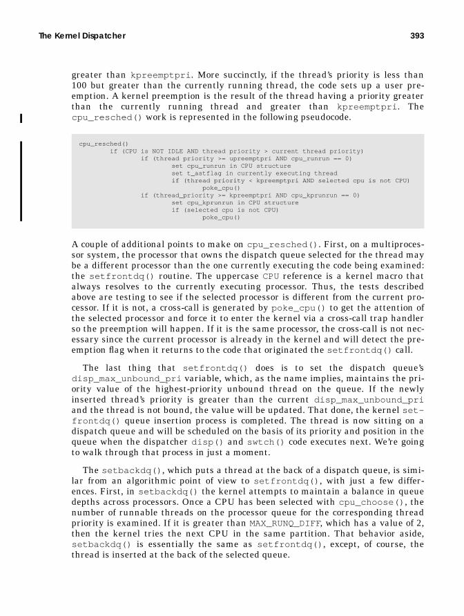
The Kernel Dispatcher 393
greater than kpreemptpri . More succinctly, if the thread’s priority is less than100 but greater than the currently running thread, the code sets up a user pre-emption. A kernel preemption is the result of the thread having a priority greaterthan the currently running thread and greater than kpreemptpri . Thecpu_resched() work is represented in the following pseudocode.
A couple of additional points to make on cpu_resched() . First, on a multiproces-sor system, the processor that owns the dispatch queue selected for the thread maybe a different processor than the one currently executing the code being examined:the setfrontdq() routine. The uppercase CPUreference is a kernel macro thatalways resolves to the currently executing processor. Thus, the tests describedabove are testing to see if the selected processor is different from the current pro-cessor. If it is not, a cross-call is generated by poke_cpu() to get the attention ofthe selected processor and force it to enter the kernel via a cross-call trap handlerso the preemption will happen. If it is the same processor, the cross-call is not nec-essary since the current processor is already in the kernel and will detect the pre-emption flag when it returns to the code that originated the setfrontdq() call.
The last thing that setfrontdq() does is to set the dispatch queue’sdisp_max_unbound_pri variable, which, as the name implies, maintains the pri-ority value of the highest-priority unbound thread on the queue. If the newlyinserted thread’s priority is greater than the current disp_max_unbound_priand the thread is not bound, the value will be updated. That done, the kernel set-frontdq() queue insertion process is completed. The thread is now sitting on adispatch queue and will be scheduled on the basis of its priority and position in thequeue when the dispatcher disp() and swtch() code executes next. We’re goingto walk through that process in just a moment.
The setbackdq() , which puts a thread at the back of a dispatch queue, is simi-lar from an algorithmic point of view to setfrontdq() , with just a few differ-ences. First, in setbackdq() the kernel attempts to maintain a balance in queuedepths across processors. Once a CPU has been selected with cpu_choose() , thenumber of runnable threads on the processor queue for the corresponding threadpriority is examined. If it is greater than MAX_RUNQ_DIFF, which has a value of 2,then the kernel tries the next CPU in the same partition. That behavior aside,setbackdq() is essentially the same as setfrontdq() , except, of course, thethread is inserted at the back of the selected queue.
cpu_resched() if (CPU is NOT IDLE AND thread priority > current thread priority) if (thread priority >= upreemptpri AND cpu_runrun == 0) set cpu_runrun in CPU structure set t_astflag in currently executing thread if (thread priority < kpreemptpri AND selected cpu is not CPU) poke_cpu() if (thread_priority >= kpreemptpri AND cpu_kprunrun == 0) set cpu_kprunrun in CPU structure if (selected cpu is not CPU) poke_cpu()

394 The Solaris Kernel Dispatcher
The decision as to whether setfrontdq() or setbackdq() is called from thevarious points in the kernel where queue insertion is called is driven by factorssuch as how long a thread has been waiting to run, whether or not the thread is inthe IA class, etc. IA class threads are put on the front of a dispatch queue, for anadditional edge on getting scheduled. A preempted thread with a scheduler activa-tion is always placed at the front of a queue. RT class threads are always placed atthe back of the kernel preempt queue. Threads that have waited a while (rela-tively speaking) to run (as determined by the thread’s t_disp_time value) areplaced at the front of a queue.
9.2.3.2 Thread Preemption
We talked a bit about thread preemption in the setfrontdq() code descriptionand referred to it in the thread priority section. To complete the picture, we’ll tieup some loose ends on the subject here. First, a quick review of what preemptionis.
The kernel will preempt a thread running on a processor when a higher-prior-ity thread is inserted onto a dispatch queue. The thread is effectively forced toreschedule itself and surrender the processor before having used up its time quan-tum. Two types of preemption conditions are implemented—a user preemption anda kernel preemption—distinguished by the priority level of the preempted thread,which drives how quickly the preemption will take place.
A user preemption occurs if a thread is placed on a dispatch queue and thethread has a higher priority than the thread currently running on the processorassociated with the queue but has a lower priority than the minimum required fora kernel preemption. A kernel preemption occurs when a thread is placed on a dis-patch queue with a priority higher than kpreemptpri , which is set to 100, repre-senting the lowest global dispatch priority for an RT class thread. RT and interruptthreads have global priorities greater than kpreemptpri .
User preemption provides for higher-priority TS/IA threads getting processortime expediently. Kernel preemption is necessary for support of real-time threads.Traditional real-time support in Unix systems was built on a kernel with variouspreemption points, allowing a real-time thread to displace the kernel at a fewwell-defined preemptable places. The Solaris implementation goes the next stepand implements a preemptable kernel with a few non-preemption points. In criti-cal code paths, Solaris will temporarily disable kernel preemption for a shortperiod and reenable it when the critical path has completed. Kernel preemption isdisabled for very short periods in the thread_create() code, during thepause_cpus() routine, and in a few memory management (MMU) code paths,such as when a hardware address translation (HAT) is being set up.
Preemptions are flagged through fields in the per-processor cpu structure:cpu_runrun and cpu_kprunrun . cpu_runrun flags a user preemption; it is setwhen a thread inserted into a dispatch queue is a higher priority than the one run-ning but a lower priority than kpreemptpri . cpu_kprunrun flags a kernel pre-

The Kernel Dispatcher 395
emption. We saw in the cpu_resched() code one example of where these flags getset. The runrun flags can also get set in the following kernel routines.
• cpupart_move_cpu() . When a processor set configuration is changed and aprocessor is moved from a processor set, the runrun flags are set to force apreemption so the threads running on the processor being moved can bemoved to another processor in the set they’ve been bound to. Note that if onlyone processor is left in the set and there are bound threads, the processor setcannot be destroyed until any bound threads are first unbound.
• cpu_surrender() . A thread is surrendering the processor it’s running on,called from the TS/IA clock tick handler, sleep code, and trap return code. TheRT class routines for enterclass , setting parameters, and clock tick handlercan also call cpu_surrender() . Recall from the section on thread prioritiesthat cpu_surrender() is called following a thread’s priority change and atest to determine if preemption conditions exist. Entering cpu_surrender()means a preemption condition has been detected and is the first step in akthread giving up a processor in favor of a higher-priority thread.Two other areas of the kernel that potentially call cpu_surrender() are thepriority inheritance code and the processor support code that handles thebinding of a thread to a processor. The conditions under which the priorityinheritance code calls cpu_surrender() are the same as previouslydescribed, that is, a priority test determined that a preemption is warranted.The thread binding code will force a preemption through cpu_surrender()when a thread is bound to a processor in a processor set and the processor thethread is currently executing on is not part of the processor set the threadwas just bound to. This is the only case when a preemption is forced that isnot the result of a priority test.cpu_surrender() will set the cpu_runrun flag and will set cpu_kprunrunif the preemption priority is greater than kpreemptpri . On a multiproces-sor system, if the processor executing the cpu_surrender() code is differ-ent from the processor that needs to preempt its thread, then a cross-call issent to the processor that needs to be preempted, forcing it into a trap han-dler. At that point the runrun flags are tested. The other possible condition isone in which the processor executing the cpu_surrender() code is the sameprocessor that must preempt the current thread, in which case it will test therunrun flags before returning to user mode; thus, the cross-call is not needed.In other words, the processor is already in the kernel by virtue of the factthat it is running the cpu_surrender() kernel routine, so a cross-call wouldbe superfluous.
Once the preemption condition has been detected and the appropriate runrun flaghas been set in the processor’s CPU structure, the kernel must enter a code paththat tests the runrun flags before the actual preemption occurs. This happens indifferent areas of the kernel for user versus kernel preemptions. User preemp-tions are tested for (cpu_runrun ) when the kernel returns from a trap or inter-

396 The Solaris Kernel Dispatcher
rupt handler. Kernel preemptions are tested for (cpu_kprunrun ) when adispatcher lock is released.
The trap code that executes after the main trap or interrupt handler has com-pleted tests cpu_runrun , and if it is set, calls the kernel preempt() function.preempt() tests two conditions initially. If the thread is not running on a proces-sor (thread state is not ONPROC) or if the thread’s dispatch queue pointer is refer-encing a queue for a processor other than the processor currently executing, thenno preemption is necessary and the code falls through and simply clears a dis-patcher lock.
Consider the two test conditions. If the thread is not running (the first test),then obviously it does not need to be preempted. If the thread’s t_disp_queuepointer is referencing a dispatch queue for a different processor (different from theprocessor currently executing the preempt() code), then clearly the thread hasalready been placed on another processor’s queue, so that condition also obviatesthe need for a preemption.
If the conditions just described are not true, preempt() increments the LWP’slrusage structure nicsw counter, which counts the number of involuntary con-text switches. The processor’s inv_switch counter is also incremented in thecpu_sysinfo structure, which counts involuntary context switches proces-sor-wide, and the scheduling-class-specific preempt code is called. The per-proces-sor counters are available with mpstat (1M), reflected in the icsw column. TheLWP lrusage data is not readily available with a bundled command, but you candevelop code that uses procfs and reads the data by means of/proc/<PID>/lwp/<LWPID>/lwpusage .
The class-specific code for TS/IA threads prepares the thread for placement on adispatch queue and calls either setfrontdq() or setbackdq() for actual queueinsertion. ts_preempt() checks whether the thread is in kernel mode andwhether the kernel-priority-requested flag (t_kpri_req ) in the thread structureis set. If it is set, the thread’s priority is set to the lowest SYS class priority (typi-cally 60). The t_trapret and t_astflag kthread flags are set, causing thets_trapret() function to run when the thread returns to user mode (from ker-nel mode). At that point, the thread’s priority is set back to something in the TS/IApriority range. ts_preempt() tests for a scheduler activation on the thread. If anactivation has been enabled and the thread has not avoided preemption beyondthe threshold of two clock ticks and the thread is not in kernel mode, then thethread’s priority is set to the highest user mode priority (59) and is placed at thefront of a dispatch queue with setfrontdq() .
If the thread’s TSBACKQflag is set, indicating the thread should be placed in theback of a dispatch queue with setbackdq() , the thread preemption is due totime-slice expiration. (Recall that ts_tick() will call cpu_surrender() .) Thethread’s t_dispwait field is zeroed, and a new time quantum is set ints_timeleft from the dispatch table (indexed with ts_cpupri , as previouslydiscussed) prior to setbackdq() being called. Otherwise, if TSBACKQis not set, a

The Kernel Dispatcher 397
real preemption occurred (higher-priority thread became runnable) and the threadis placed at the front of a dispatch queue.
The rt_preempt() code is much less complex. If RTBACKQis true, the preemp-tion was due to a time quantum expiration (as was the case previously), and set-backdq() is called to place the thread at the back of a queue after setting thert_timeleft value from rt_pquantum . Otherwise, the thread is placed at thefront of a dispatch queue with setfrontdq() .
The class-specific preempt code, once completed, returns to the generic pre-empt() routine, which then enters the dispatcher by calling swtch() . We look atthe swtch() code in the next section.
Kernel preemption, as we said earlier, is detected when a dispatcher lock isreleased. It is also tested for in kpreempt_enable() , which reenables kernel pre-emption after kpreempt_disable() blocked preemptions for a short time. Thegoal is to have kernel preemptions detected and handled more expediently (withless latency) than user preemptions. A dispatcher lock is a special type of mutexlock that not only provides mutual exclusion semantics for access to a specific dis-patch queue, but does so at a raised priority level, protecting the queue from accessfrom an interrupt handler for a low-priority interrupt. Dispatcher locks areacquired and held at priority level 10 on SPARC systems, blocking all low-priorityinterrupts. Interrupts above level 10 are high priority, and handlers for high-prior-ity interrupts are not permitted to execute code that may require entering the dis-patcher (e.g., causing a sleep and context switch). Every dispatch queue has adisp_lock , maintained in the dispatch queue structure that describes the queue(see Figure 9.5 on page 374).
Because the test for a kernel preemption, cpu_kprunrun , is put in thedisp_lock_exit() code, the detection happens synchronously with respect toother thread scheduling and queue activity. The dispatcher locks are acquired andfreed at various points in the dispatcher code, either directly through the dis-patcher lock interfaces or indirectly through macro calls. For example, each kernelthread maintains a pointer to a dispatcher lock, which serves to lock the threadand the queue during dispatcher functions. The THREAD_LOCK andTHREAD_UNLOCKmacros use the dispatcher lock entry and exit functions. The keypoint is that a kernel preemption will be detected before a processor running athread flagged for preemption completes a pass through the dispatcher.
When disp_lock_exit() is entered, it tests whether cpu_kprunrun is set; ifso, then disp_lock_exit() calls kpreempt() . A clear cpu_kprunrun flag indi-cates a kernel preemption is not pending, so there is no need to call kpreempt() .

398 The Solaris Kernel Dispatcher
Kernel preemptions are handled by the kpreempt() code, represented here inpseudocode.
The preceding pseudocode basically summarizes at a high level what happens inkpreempt() . Kernel threads have a t_preempt flag, which, if set, signifies thethread is not to be preempted. This flag is set in some privileged threads, such as aprocessor’s idle and interrupt threads. Kernel preemption is disabled by incre-menting t_preempt in the current thread and is reenabled by decrementingt_preempt . kpreempt() tests t_preempt in the current thread; if t_preempt isset, kpreempt() increments some statistics counters and returns. If t_preemptis set, the code will not perform a kernel preemption.
The second test is similar in logic to what happens in the preempt() code pre-viously described. If the thread is not running or is not on the current processor’sdispatch queue, there’s no need to preempt. The third test checks the priority levelof the processor. If we’re running at a high PIL, we cannot preempt the thread,since it may be holding a spin lock. Preempting a thread holding a lock couldresult in a deadlock situation.
Any of the first three test conditions evaluating true will cause kpreempt() toreturn without actually doing a preemption. Assuming the kernel goes ahead withthe preemption, kernel preemptions are disabled (to prevent nested kernel pre-emptions) and the preempt() function is called. Once preempt() completes, ker-nel preemption is enabled and kpreempt() is done.
The kernel statistical data maintained for kernel preemption events is notaccessible with a currently available Solaris command. The data is maintained in
kpreempt() if (current_thread->t_preempt) do statistics return if (current_thread NOT running) OR (current_thread NOT on this CPUs queue) return if (current PIL >= LOCK_LEVEL) return block kernel preemption (increment current_thread->t_preempt) call preempt() enable kernel preemption (decrement current_thread->t_preempt)

The Kernel Dispatcher 399
a kpreempt_cnts (kernel preemption counts) data structure and can be interro-gated with adb (1).
In the example, we inserted a short description of the event each counter corre-lates to. Most of the descriptions are comprehensible when examined in conjunc-tion with the preceding text. The last two counters, async preempts and syncpreempts, count each of the possible methods of kernel preemption. The kpre-empt() function is passed one argument, asyncspl . For async preempts, async-spl is a priority-level argument, and the kpreempt() code will raise the PIL, asdictated by the value passed. Sync preempts pass a −1 argument and do notchange the processor’s priority level.
Thread preemption is a relatively simple concept to understand, but as withmany other things, it’s easy to get lost in the details of implementation. Figure9.10 summarizes thread preemption at a high level.
# adb -k /dev/ksyms /dev/memphysmem fddekpreempt_cnts/Dkpreempt_cnts:kpreempt_cnts: 0 <- Idle threadkpreempt_cnts+4: 3 <- Interrupt threadkpreempt_cnts+8: 0 <- Clock threadkpreempt_cnts+0xc: 37<- Blocked *t_preempt is set)kpreempt_cnts+0x10: 32<- Not on Prockpreempt_cnts+0x14: 0<- Inv Switchkpreempt_cnts+0x18: 15<- Priority to Highkpreempt_cnts+0x1c: 35<- Async Preemptskpreempt_cnts+0x20: 593759<- Sync Preempts
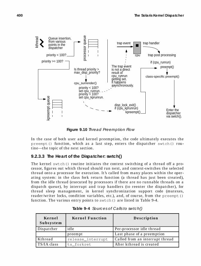
400 The Solaris Kernel Dispatcher
Figure 9.10 Thread Preemption Flow
In the case of both user and kernel preemption, the code ultimately executes thepreempt() function, which as a last step, enters the dispatcher swtch() rou-tine—the topic of the next section.
9.2.3.3 The Heart of the Dispatcher: swtch()
The kernel swtch() routine initiates the context switching of a thread off a pro-cessor, figures out which thread should run next, and context-switches the selectedthread onto a processor for execution. It’s called from many places within the oper-ating system: in the class fork return function (a thread has just been created),from the idle thread (executed by processors if there are no runnable threads on adispatch queue), by interrupt and trap handlers (to reenter the dispatcher), forthread sleep management, in kernel synchronization support code (mutexes,reader/writer locks, condition variables, etc.), and, of course, from the preempt()function. The various entry points to swtch() are listed in Table 9-4.
Table 9-4 Sources of Calls to swtch()
KernelSubsystem
Kernel Function Description
Dispatcher idle Per-processor idle threadpreempt Last phase of a preemption
Kthread release_interrupt Called from an interrupt threadTS/IA class ts_forkret After kthread is created
proc
esso
r que
ue
kpre
empt
que
ue
priority < 100?
priority >= 100?
Is thread priority >max_disp_priority?
cpu_surrender()
priority < 100?set cpu_runrun.priority > 100?set cpu_kprunrun.
cpu
trap event trap handler
trap post processing
if (cpu_runrun)preempt()
class-specific preempt()
Enter thedispatchervia swtch().
kthr
ead
disp_lock_exit()if (cpu_kprunrun)
kpreempt()
Queue insertion,from variouspoints in thedispatcher
The trap eventis not a directresult ofcpu_runrungetting set.It happensasynchronously.

The Kernel Dispatcher 401
Entering the swtch() routine causes the cpu_sysinfo.pswtch counter to beincremented, as reported in mpstat (1M) in the csw column, and reflects the num-ber of context switches per second, on a per-processor basis.
The swtch() function first checks to see if the current thread is an interruptthread. When interrupts happen, the thread stack is switched to that of an inter-rupt thread, from the linked list of interrupt threads in the processor’s cpu struc-ture. If swtch() was entered with an interrupt thread as the current thread, thekernel must restore the interrupted thread’s state so it can be resumed. The inter-rupted thread is unpinned (a thread that has been preempted for an interrupt isconsidered pinned), and the kernel resume_from_interrupt() assembly rou-tine is called to restore the state of the interrupted thread.
If the thread is not an interrupt thread, the code tests the handoff pointer in thekernel thread (t_handoff ). A non-NULL t_handoff pointer indicates the proces-sor should be handed off to another thread, in support of scheduler activations.(Scheduler activations were first introduced in Solaris 2.6 and are discussed in“Scheduler Activations” on page 415.)
Briefly, one of the goals of scheduler activations is to provide a framework forcommunication between the kernel dispatcher and the user-level threads library.Such communication improves the scheduling of user threads and reduces thelatency of a runnable user thread getting an LWP if all the LWPs in a process areblocked. Recall from an earlier discussion that a user-level thread, that is, a threadcreated through a thr_create (3T) or pthread_create (3T) call, is mapped ontoan LWP by the user thread’s scheduler. If all the LWPs in a process are blockedand there are runnable user threads, the user thread’s scheduler does not have theresource it needs, an LWP, to schedule a user thread. Prior to Solaris 2.6, the ker-
Sleep/wakeup cv_ xxxx Various conditional variable func-tions
CPU force_migrate Thread migration to another pro-cessor
cpu_pause Processor state change to pauseMutex mutex_vector_enter Mutex lock acquisitionRWlock rw_enter_sleep RW lock acquisitionMemoryscheduler
sched PID 0
Semaphore sema_p Semaphore “p” operationSignal stop Thread stop functionSleep/wakeup slp_cv_wait Thread to sleep stateInterrupt intr_thread_exit Exit of an interrupt handler
Table 9-4 Sources of Calls to swtch() (Continued)
KernelSubsystem
Kernel Function Description

402 The Solaris Kernel Dispatcher
nel implemented a signal mechanism, using SIGWAITING in conjunction with asignal handler for SIGWAITING, to increase the pool of available LWPs for the pro-cess.
With scheduler activations, a communication path is established between thekernel and the user threads library. If an activation has been established for theprocess, a pool of LWPs might be readily available, in which case the t_handoffpointer would be non-NULL. If that is the case, a kernel handoff function is called,and ultimately the kernel resume() code is entered to context-switch the kernelthread referenced with t_handoff onto the processor.
If the current thread is not an interrupt thread and a handoff is not required,swtch() calls the disp() function, which is the code segment that looks for thehighest-priority thread to run, sets the thread’s state to running (TS_ONPROC), andarranges for it to be switched onto a processor. At a high level, the disp() func-tion searches the dispatch queues for the best-priority kernel thread, starting withthe kernel preempt queue and then searching the queue of the current processor—that is, the processor executing the disp() code. If those searches come up blank,then the code searches the dispatch queues of other processors on a multiproces-sor system, looking for a runnable kernel thread. If no threads are found on thedispatch queues, the processor executes its idle thread, which executes a tight loop,testing for runnable threads on each pass through the loop and entering swtch()if the run count is greater than 0.
The search for the highest-priority thread begins with the kernel preemptqueue, as referenced by the current processor through its cpu_part structure,where the preempt queue is linked to cp_kp_queue . In this case, on a system withmultiple processor partitions (user processor sets—recall there is a kernel pre-empt queue per processor set), the preempt queue for the processor partition thatthe executing processor belongs to is searched first. The cp_kp_queue search isrepresented in the following pseudocode.
The preceding queue search loop validates the priority value according to thequeue’s disp_maxrunpri , which reflects the highest-priority thread sitting on thequeue, makes sure the current processor is not offline, and calls the dispatcherdisp_getbest() code to fetch the best-priority thread from the kernel preemptqueue. disp_getbest() finds the highest-priority unbound thread, calls disp-
kpq = pointer to kernel preempt queuedq = pointer to processor’s dispatch queuewhile ( priority = kpq->dispmaxrunpri >= 0 ) AND ( priority >= dq->dispmaxrunpri) AND ( the current CPU is NOT offline) AND ( thread_pointer = disp_getbest(kpq) != NULL ) if (disp_ratify(thread_pointer, kpq) != NULL) return(thread_pointer)

The Kernel Dispatcher 403
deq() to have the thread removed from the dispatch queue, and returns thethread pointer back to disp() . If nothing is found, a NULL value is returned.
If an unbound thread is found in disp_getbest() , the thread is dequeued withdispdeq() , the thread’s t_disp_queue pointer is set to reference the processor’scpu structure cpu_disp queue pointer, the processor’s cpu_dispthread pointeris set to the selected thread pointer, and the thread state is set to ONPROC.
dispdeq() deals with updating the dispatch queue data structures with theselected thread removed from the queue. It decrements disp_nrunnable , whichis the total count for all the queues, and dq_sruncnt , which maintains the countof runnable threads at the same priority (refer to Figure 9.5 on page 374). If theper-priority queue count, dq_sruncnt , is 0, then the queue bitmap is updated toreflect an empty queue. The disp_qactmap bitmap uses a set bit to reflect thepresence of runnable threads on a per-priority queue; thus, the bit that corre-sponds to the zeroed queue is cleared. The disp_maxrunpri anddisp_max_unbound_pri fields are also updated to reflect the new highest-prior-ity thread on the queue if it is different from the thread that has just beenremoved from the queue.
Once the thread selection has been made and the thread dequeued, the codereturns to disp() , which calls disp_ratify() to ensure that the selected threadwas, in fact, the best candidate to run next. The fine-grained locking used withinthe dispatcher routines allows for simultaneous changes to be made to the queuesand the queue state by potentially many processors. For this reason, aselect-and-ratify algorithm was chosen for implementation. The select phase of thealgorithm now completed, disp_ratify() is entered to complete the ratify phase.The ratify code simply compares the priority of the selected thread to thedisp_maxrunpri values of the processor and kernel preempt queue. If theselected thread priority is greater than maxrunpri , the selection is ratified andthe context switch is done. If not, we reenter the code loop to find the best runna-ble thread. More precisely, if a higher-priority thread appears on the queue whendisp_ratify() executes, the selected thread is placed back on the dispatchqueue with a call to setfrontdq() and disp_ratify() returns NULLto disp() .
disp_getbest() dpq = dispatch queue pointer (cp_kp_queue in this example) priority = dpq->disp_max_unbound_pri if (priority == -1) return(NULL) queue = dpq->disp_q[pri]; thread_pointer = queue->dq_first; loop through linked list of threads on queue, skip bound threads if (no unbound threads) return NULL else thread_pointer = thread found dispdeq(thread_pointer) set thread t_disp_queue, processorUs cpu_dispthread, thread state to ONPROC return (thread_pointer)

404 The Solaris Kernel Dispatcher
If a thread is not found on the kernel preempt queue, then the per-processorqueue disp_maxrunpri is tested. A value of −1 means that nothing is on thequeue. In that case, the code searches the queues of the other processors on thesystem, beginning with the disp_getwork( ) code, which finds a processor withthe highest-priority thread. Then, the code uses the disp_getbest() anddisp_ratify() functions previously described.
If the current processor’s disp_maxrunpri indicates runnable threads, the firstthread from the highest priority queue is removed, the queue data is updated(disp_nrunnable , dq_nruncnt , disp_qactmap , disp_max_unbound_pri , anddisp_maxrunpri ), the selection is ratified, and disp() returns the threadpointer to swtch() .
If no work is found on any of the dispatch queues, the processor’s idle thread isselected by setting the thread pointer to the cpu_idle_thread , referenced fromthe processor’s cpu structure. The pointer to the idle thread is returned to theswtch() code.
Back in swtch() , with a thread pointer for the selected thread (or idle thread),the kernel resume() code is called to handle the switching of the thread on theprocessor. resume() is implemented in assembly language because the process ofcontext switching requires low-level contact with processor hardware, for two rea-sons: to save the hardware context of the thread being switched off; and to set upthe hardware registers and other context information so the new thread can beginexecution.
9.3 The Kernel Sleep/Wakeup Facility
The typical lifetime of a kernel thread includes not only execution time on a pro-cessor but also time spent waiting for requested resources to become available. Anobvious example is a read or write from disk, when the kernel thread will issue theread (2) or write (2) system call, then sleep so another thread can make use of theprocessor while the I/O is being processed by the kernel. Once the I/O has beencompleted, the kernel will wake up the thread so it can continue its work.
Kernel threads that are runnable and waiting for a processor reside on dispatchqueues. Kernel threads that must block, waiting for an event or resource, areplaced on sleep queues. A kernel thread is placed on a sleep queue when it needsto sleep, awaiting availability of a resource (e.g., a mutex lock, reader/writer lock,etc.) or awaiting some service by the kernel (e.g., a system call). A few sleep queuesimplemented in the kernel vary somewhat, although they all use the same under-lying sleep queue structures. Turnstiles are implemented with sleep queues andare used specifically for sleep/wakeup support in the context of priority inherit-ance, mutex locks, and reader/writer locks. Kernel threads put to sleep for some-thing other than a mutex or reader/writer lock are placed on the system’s sleep

The Kernel Sleep/Wakeup Facility 405
queues. Turnstiles and priority inheritance are discussed in Chapter 2, “KernelSynchronization Primitives.”
9.3.1 Condition Variables
The underlying synchronization primitive used for sleep/wakeup in Solaris is thecondition variable. Condition variables are always used in conjunction with mutexlocks. A condition variable call is issued on the basis of a specific condition beingeither true or false. The mutex ensures that the tested condition cannot be alteredduring the test and maintains state while the kernel thread is being set up toblock on the condition. Once the condition variable code is entered and the threadis safely on a sleep queue, the mutex can be released. This is why all entry pointsto the condition variable code are passed the address of the condition variable andthe address of the associated mutex lock.
In implementation, condition variables are data structures that identify anevent or a resource for which a kernel thread may need to block and are used inmany places around the operating system. The structure itself is quite small (seeFigure 9.11) and can be examined in /usr/include/sys/condvar.h and/usr/include/sys/condvar_impl.h .
Figure 9.11 Condition Variable
The condition variable itself is simply a 2-byte (16-bit) data type with one definedfield, cv_waiters , that stores the number of threads waiting on the specificresource the condition variable has been initialized for. The implementation issuch that the various kernel subsystems that use condition variables declare acondition variable data type with a unique name either as a standalone data itemor embedded in a data structure. Try doing a grep (1) command on kcondvar_t inthe /usr/include/sys directory, and you’ll see dozens of examples of conditionvariables. A generic kernel cv_init() function sets the condition variable to allzeros during the initialization phase of a kernel module. Other kernel-level condi-tion variable interfaces are defined and called by different areas of the operatingsystem to set up a thread to block a particular event and to insert the kernelthread on a sleep queue.
At a high level, the sleep/wakeup facility works as follows. At various points inthe operating system code, conditional tests are performed to determine if a spe-cific resource is available. If it is not, the code calls any one of several conditionvariable interfaces, such as cv_wait() , cv_wait_sig() , cv_timedwait() ,
015cv_waiters
condvar_impl_t

406 The Solaris Kernel Dispatcher
cv_wait_stop() , etc., passing a pointer to the condition variable and mutex.This sequence is represented in the following small pseudocode segment.
These interfaces provide some flexibility in altering behavior as determined by thecondition the kernel thread must wait for. Ultimately, the cv_block() interface iscalled; the interface is the kernel routine that actually sets the t_wchan value inthe kernel thread and calls sleepq_insert() to place the thread on a sleepqueue. The t_wchan , or wait channel, contains the address of the conditional vari-able that the thread is blocking on. This address is listed in the output of a ps-efl command, in the WCHAN column.
The notion of a wait channel or wchan is something that’s familiar to folks thathave been around Unix for a while. Traditional implementations of Unix main-tained a wchan field in the process structure, and it was always related to an eventor resource the process was waiting for (why the process was sleeping). Naturally,in the Solaris multithreaded model, we moved the wait channel into the kernelthread, since kernel threads execute independently of other kernel threads in thesame process and can execute system calls and block.
When the event or resource that the thread was sleeping on is made available,the kernel uses the condition variable facility to alert the sleeping thread (orthreads) and to initiate a wakeup, which involves moving the thread from a sleepqueue to a processor’s dispatch queue.
Figure 9.12 illustrates the sleep/wake process.
kernel_function() mutex_init(resource_mutex); cv_init(resource_cv); mutex_enter(resource_mutex); if (resource is not available) cv_wait(&resource_cv, &resource_mutex); consume resource mutex_exit(resource_mutex);
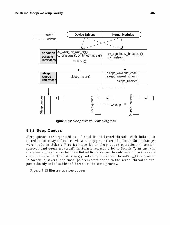
The Kernel Sleep/Wakeup Facility 407
Figure 9.12 Sleep/Wake Flow Diagram
9.3.2 Sleep Queues
Sleep queues are organized as a linked list of kernel threads, each linked listrooted in an array referenced via a sleepq_head kernel pointer. Some changeswere made in Solaris 7 to facilitate faster sleep queue operations (insertion,removal, and queue traversal). In Solaris releases prior to Solaris 7, an entry inthe sleepq_head array begins a linked list of kernel threads waiting on the samecondition variable. The list is singly linked by the kernel thread’s t_link pointer.In Solaris 7, several additional pointers were added to the kernel thread to sup-port a doubly linked sublist of threads at the same priority.
Figure 9.13 illustrates sleep queues.
conditionvariableinterfaces
Device Drivers Kernel Modules
Sle
ep q
ueue
s
Sle
ep q
ueue
s
Dis
patc
h qu
eues
wakeup
sleepwakeup
sleepqueueinterfaces
cv_wait(), cv_wait_sig(),cv_timedwait(), cv_timedwait_sig()
cv_block()
cv_signal(), cv_broadcast(),cv_unsleep()
sleepq_insert()sleepq_wakeone_chan(),sleepq_wakeall_chan()
sleepq_unsleep()

408 The Solaris Kernel Dispatcher
Figure 9.13 Solaris 2.5.1 and Solaris 2.6 Sleep Queues
In all implementations (pre- and post-Solaris 7, that is), a hashing functionindexes the sleepq_head array, hashing on the address of the condition variable.In the pre-Solaris 7 implementation, kernel threads are inserted on the list inorder of descending priority. In Solaris 7, the singly linked list that establishes thebeginning of the doubly linked sublists of kthreads at the same priority is also inascending order of priority. The sublist is implemented by t_priforw (forwardpointer) and t_priback (previous pointer) in the kernel thread. Also, a t_sleepqpointer was added to point back to the array entry in sleepq_head , identifyingwhich sleep queue the thread is on and also providing a quick method to deter-mine if a thread is on a sleep queue at all. (If t_sleepq == NULL , the thread isnot on a sleep queue.)
Figure 9.14 illustrates priority order on sleep queues.
sq_locksq_first
sq_locksq_first
sq_locksq_first
sq_locksq_first
t_link
t_link
t_link
t_link
t_link
t_linkt_linksleepq_head
Kernel threads linked together aresleeping on the same condition variable.
slee
p qu
eues
kernel threads

The Kernel Sleep/Wakeup Facility 409
Figure 9.14 Solaris 7 Sleep Queues
The number of kernel interfaces to the sleep queue facility is minimal. Only a fewoperations that are performed on sleep queues: the insertion of a kernel thread ona sleep queue (putting a thread to sleep), the removal of a thread from a sleepqueue (waking a thread up), and traversing the sleep queue in search of a kernelthread. There are interfaces that provide for waking up only one thread or allthreads sleeping on the same condition variable.
Insertion of a kthread simply involves indexing into the sleepq_head array tofind the appropriate sleep queue specified by the condition variable address, thentraversing the list, checking thread priorities along the way to determine theproper insertion point. Once the appropriate sublist has been found (at least onekernel thread at the same priority) or it has been determined that no otherthreads on the sleep queue have the same priority, a new sublist is started, thekernel thread is inserted, and the pointers are set up properly.
The removal of a kthread either involves searching for and removing a specificthread that has been specified by the code calling into sleepq_dequeue() orsleepq_unsleep() , or waking up all the threads blocking on a particular condi-tion variable. Waking up all threads or a specified thread is relatively straightfor-ward: hash into the sleepq_head array specified by the address of the conditionvariable, and walk the list, either waking each thread up or searching for a partic-ular kthread and waking the targeted thread. In case a single, unspecified kthreadneeds to be removed, the code implements the list as a FIFO (First In, First Out),so the kthread that has been sleeping the longest on a condition variable will beselected for wakeup first.
sq_locksq_first
sq_locksq_first
sq_locksq_first
sq_locksq_first
sleepq_head
slee
p qu
eues
t_linkt_priforwt_pribackt_sleepq
t_linkt_priforwt_pribackt_sleepq
t_linkt_priforwt_pribackt_sleepq
t_linkt_priforwt_pribackt_sleepq
t_linkt_priforwt_pribackt_sleepq
Kthreads along this list are sleeping on the same CV. List is in descending priority order.
Kthr
eads
alo
ng th
is li
st a
re a
t the
sam
e pr
iorit
y.

410 The Solaris Kernel Dispatcher
9.3.3 The Sleep Process
Now that we’ve introduced condition variables and sleep queues, let’s tie themtogether to form the complete sleep/wakeup picture in Solaris. The interfaces tothe sleep queue (sleepq_insert() , etc.) are, for the most part, called only fromthe condition variables and turnstiles subsystems. From a hierarchical perspec-tive, you could view the sleep/wakeup implementation, as depicted in Figure 9.12on page 407, where a well-defined and limited set of interfaces manipulate kernelthreads on the sleep queues.
The process of putting a thread to sleep begins with a call into the conditionvariable code wait functions, one of cv_wait() , cv_wait_sig() ,cv_wait_sig_swap() , cv_timedwait() , or cv_timedwait_sig() . Each ofthese functions is passed the condition variable and a mutex lock. They all ulti-mately call cv_block() to prepare the thread for sleep queue insertion.cv_wait() is the simplest condition variable sleep interface; it grabs the dis-patcher lock for the kthread and invokes the class-specific sleep routine (e.g.,ts_sleep() ). The timed variants of the cv_wait() routines take an additionaltime argument, ensuring that the thread will be woken up when the time valueexpires if it has not yet been removed from the sleep queue. cv_timedwait() andcv_timedwait_sig() use the kernel callout facility for handling the timer expi-ration. The realtime_timeout() interface is used and places a high-prioritytimeout on the kernel callout queue. The setrun() function is placed on the call-out queue, along with the kernel thread address and time value. When the timerexpires, setrun() , followed by the class-specific setrun function (e.g.,rt_setrun() ), executes on the sleeping thread, making it runnable and placing iton a dispatch queue.
The sig variants of the condition variable code, cv_wait_sig() ,cv_timedwait_sig() , etc., are designed for potentially longer-term waits, whereit is desirable to test for pending signals before the actual wakeup event. Theyreturn 0 to the caller if a signal has been posted to the kthread. The swap variant,cv_wait_sig_swap() , can be used if it is safe to swap out the sleeping threadwhile it’s sleeping. The various condition variable routines are summarized below.Note that all functions described below release the mutex lock after cv_block()returns, and they reacquire the mutex before the function itself returns.
• cv_wait() — Calls cv_block() . Then, cv_wait() enters the dispatcherwith swtch() when cv_block() returns.
• cv_wait_sig() — Checks for SC_BLOCKscheduler activation (last LWP inthe process is blocking). If false , cv_wait_sig() calls cv_block_sig() .On return from cv_block_sig() , it tests for a pending signal. If a signal ispending, cv_wait_sig() calls setrun() ; otherwise, it calls swtch() . If anSC_BLOCKactivation is true , cv_wait_sig() removes the thread timeoutand returns −1, unless a signal is pending; then, it returns 0.
• cv_wait_sig_swap() — Essentially the same as cv_wait_sig() but flagsthe thread as swappable.

The Kernel Sleep/Wakeup Facility 411
• cv_timedwait() — Tests for timer expiration on entry. If the timer hasexpired, cv_timedwait() returns −1. It calls realtime_timeout() to setcallout queue entry, calls cv_block() , and checks the timer on return fromcv_block() . If the timer has expired, cv_timedwait() calls setrun() ;otherwise, it calls swtch() .
• cv_timedwait_sig() — Tests for time expiration. If the timer has expired,cv_timedwait_sig() returns −1 unless a signal is pending; then, it returns0. If neither condition is true , then cv_timedwait_sig() callsrealtime_timeout() to set the callout queue entry and tests for anSC_BLOCK activation. If false , cv_timedwait_sig() callscv_block_sig() . On return from cv_block_sig() , it tests for a pendingsignal. If a signal is pending, cv_timedwait_sig() calls setrun() ; other-wise, it calls swtch() . If an SC_BLOCK activation is true ,cv_timedwait_sig() removes the thread timeout and returns −1 unless asignal is pending; then, it returns 0.
All of the above entry points into the condition variable code call cv_block() orcv_block_sig() , which just sets the T_WAKEABLEflag in the kernel thread andthen calls cv_block() . cv_block() does some additional checking of variousstate flags and invokes the scheduling-class-specific sleep function through theCL_SLEEP() macro, which resolves to ts_sleep() for a TS or IA class thread.The intention of the ts_sleep() code is to boost the priority of the sleepingthread to a SYSpriority if such a boost is flagged. As a result, the kthread is placedin an optimal position on the sleep queue for early wakeup and quick reschedulingwhen the wakeup occurs. Otherwise, the priority is reset according to how long thethread has been waiting to run.
The assignment of a SYS priority to the kernel thread is not guaranteed everytime ts_sleep() is entered. Flags in the kthread structure, along with thekthread’s class-specific data (ts_data in the case of a TS class thread), specifywhether a kernel mode (SYS) priority is required. A SYSclass priority is flagged ifthe thread is holding either a reader/writer lock or a page lock on a memory page.For most other cases, a SYS class priority is not required and thus will not beassigned to the thread. RT class threads do not have a class sleep routine; because

412 The Solaris Kernel Dispatcher
they are fixed-priority threads, there’s no priority adjustment work to do. Thets_sleep() function is represented in the following pseudocode.
The thread priority setting in ts_sleep() in the second code segment above isentered if the thread has been waiting an inordinate amount of time to run, asdetermined by ts_dispwait in the ts_data structure, and by the ts_maxwaitvalue from the dispatch table, as indexed by the current user mode priority,ts_umdpri . The sequence is represented graphically in Figure 9.15.
Figure 9.15 Setting a Thread’s Priority in ts_sleep()
The code will return to cv_block() from ts_sleep() , where the kthreadst_wchan is set to the address of the condition variable and the kthreadst_sobj_ops is set to the address of the condition variable’s operations structure.
ts_sleep() if (SYS priority requested) /* t)_kpri_req flag */ set TSKPRI flag in kthread set t_pri to requested SYS priority /* tpri = ts_kmdpris[arg] */ set kthread trap return flag /* t_trapret */ set thread ast flag /* t_astflag */ else if (ts_dispwait > ts_maxwait) /* has the thread been waiting long */ calculate new user mode priority set ts_timeleft = ts_dptbl[ts_cpupri].ts_quantum set ts_dispwait = 0 set new global priority in thread (t_pri) if (thread priority < max priority on dispatch queue) call cpu_surrender() /* preemption time */ else if (thread is already at a SYS priority) set thread priority to TS class priority clear TSKPRI flag in kthread if (thread priority < max priority on dispatch queue) call cpu_surrender() /* preemption time */
t_pri
ts_cpuprits_umdpri
kthread
tsproc
ts_g
lobp
ri
ts_q
uant
um
ts_t
qexp
ts_s
lpre
t
ts_m
axw
ait
ts_l
wai
t
1
2
34
ts_dptbl
ts_timeleftts_dispwait
...
5
if (tsproc.ts_dispwait > ts_dptbl[ts_umdpri].ts_maxwait)
.6

The Kernel Sleep/Wakeup Facility 413
If you take a look at /usr/include/sys/sobject.h , you’ll find a definition for asynchronization object operations structure.
This is a generic structure that is used for all types of synchronization objects sup-ported by the operating system. Note the enumerated types in the same headerfile; they describe mutex locks, reader/writer locks, semaphores, condition vari-ables, etc. Essentially, this object provides a placeholder for a few routines specificto the synchronization object that may require invocation while the kernel threadis sleeping. In the case of condition variables (our example), the sobj_ops struc-ture is populated with the address of the cv_owner() , cv_unsleep() , andcv_change_pri() functions, with the sobj_type field set to SOBJ_CV. Theaddress of this structure is what the kthread’s t_sobj_ops field is set to in thecv_block() code.
With the kthread’s wait channel and synchronization object operations pointersset appropriately, the correct sleep queue is located by use of the hashing functionon the condition variable address to index into the sleepq_head array. Next, thecv_waiters field in the condition variable is incremented to reflect another ker-nel thread blocking on the object, and the thread state is set to TS_SLEEP. Finally,the sleepq_insert() function is called to insert the kernel thread into the cor-rect position (based on priority) in the sleep queue. The kthread is now on a sleepqueue in a TS_SLEEP state, waiting for a wakeup.
9.3.4 The Wakeup Mechanism
For every cv_wait() (or variant) call on a condition variable, a correspondingwakeup call uses cv_signal() , cv_broadcast() , or cv_unsleep() . In prac-tice, cv_unsleep() is not called in current versions of Solaris. cv_signal()wakes up one thread, and cv_broadcast() wakes up all threads sleeping on thesame condition variable. Here is the sequence of wakeup events.
• The cv_broadcast() function simply locates the address of the sleep queueby invoking the hash function on the address of the condition variable, whichwas passed to cv_broadcast() as an argument, clears the cv_waitersfield in the condition variable (all the threads are getting a wakeup, so thecondition variable should reflect zero threads waiting on the condition vari-able), and calls sleepq_wakeall_chan() .
typedef struct _sobj_ops { syncobj_t sobj_type; kthread_t *(*sobj_owner)(); void (*sobj_unsleep)(kthread_t *); void (*sobj_change_pri)(kthread_t *, pri_t, pri_t *);} sobj_ops_t;
Header File <sys/sobject.h>

414 The Solaris Kernel Dispatcher
• In Solaris 7, sleepq_wakeall_chan() traverses the linked list of kernelthreads waiting on that particular condition variable and, for each kthread,calls sleepq_unlink() . sleepq_unlink() removes the kthread from thesleep queue linked list, adjusts the pointers (the t_priforw , t_pribackpointers) and returns to sleepq_wakeall_chan() .
• On the return to sleepq_wakeall_chan() , the kthread’s t_wchan andt_sobj_ops fields are cleared, and the scheduling-class-specific wakeup codeis called.
For TS/IA threads, the code is ts_wakeup() ; for RT class threads, it isrt_wakeup() . In Solaris 2.5.1 and Solaris 2.6, the queue is a singly linkedlist, linked with the t_link pointer in the kthread.Solaris 2.5.1 and Solaris 2.6 do not have a sleepq_unlink() function, sosleep_wakeall_chan() removes each thread from the list and sets thethread’s t_link , t_wchan , and t_sobj_ops fields to NULL.
• cv_signal() locates the correct index into the sleepq_head array by hash-ing on the address of the condition variable, decrements the cv_waitersfield in the condition variable by 1, since only one thread is getting a wakeup,and calls sleepq_wakeone_chan() .
• The ts_wakeup() code puts the kernel thread back on a dispatch queue so itcan be scheduled for execution on a processor.Threads that have a kernel mode priority (as indicated by the TSKPRI flag inthe class-specific data structure, which is set in ts_sleep() if a SYSpriorityis assigned) are placed on the front of the appropriate dispatch queue. IAclass threads will also result in setfrontdq() being called; otherwise, set-backdq() is called to place the kernel thread at the back of the dispatchqueue.
• Threads that are not at a SYS priority are tested to see if they’ve waitedlonger for a shot at getting scheduled than the time value set in thets_maxwait field in the dispatch table for the thread’s priority level.
If the thread has been waiting an inordinate amount of time to run (if disp-wait > dispatch_table[priority]dispwait ), then the thread’s priorityis recalculated, using the ts_slpret value from the dispatch table. This isessentially the same logic used in ts_sleep() and gives a priority boost tothreads that have spent an inordinate amount of time on the sleep queue.
It is in the dispatcher queue insertion code (setfrontdq() , setbackdq() ) thatthe thread state is switched from TS_SLEEPto TS_RUN. It’s also in these functionsthat we determine if the thread we just placed on a queue is of a higher prioritythan the currently running thread and if so, force a preemption. At this point, thekthread has been woken up, is sitting on a dispatch queue, ready to get con-text-switched onto a processor when the dispatcher swtch() function runs againand the newly inserted thread is selected for execution.

Scheduler Activations 415
9.4 Scheduler Activations
We made several references to scheduler activations in the preceding text andhighlighted the preemption control feature in the thread priority descriptions.Scheduler activations were added to Solaris 2.6 to address several deficiencies inthe two-level threads architecture of Solaris and to provide a facility for short-termpreemption control by a process. (This section and any previous references toscheduler activations do not apply to Solaris 2.5.1; they apply only to Solaris 2.6and Solaris 7).
The two levels in the design refer to user-level threads and the underlyingkthread/LWP. We use the term LWP from this point forward when discussing thekernel level, and we use threads to refer to a user thread created from the threadslibrary. User-level threads are scheduled within the framework of the threadslibrary—the user threads actually participate in their own scheduling through pre-emption points and internal threads library routines. User threads are, by design,not visible to the kernel. The priority of a user thread has no bearing on the sched-uling or priority of an LWP linked to the thread for execution.
Prior to Solaris 2.6, there was no facility for communication between the userthreads scheduler and the kernel dispatcher (see Figure 9.16), and thus no correla-tion between the priority of a user thread and the priority of the underlying LWP.This problem could be circumvented to some extent by the use of bound threads,where every user thread was bound to an LWP, and priority control facilities (pri-ocntl (1M)) managed execution priorities at the LWP level.
Figure 9.16 Two-Level Threads Model
user threads
LWP
LWP/
Kthr
ead
process Kernel dispatcherschedules theseonto processors.Kernel globalpriority scheme.processor
user
kernel
LWP/
Kthr
ead
LWP no communication
User threads schedulethemselves ontoavailable LWPs.

416 The Solaris Kernel Dispatcher
Other problems existed in the area of synchronization primitives used by threadedprograms. At the user threads level, the use of mutex locks and other synchroniza-tion mechanisms were prone to priority inversion problems. We described how pri-ority inheritance addressed this problem in the kernel for kernel synchronizationprimitives. There was no means by which an inheritance scheme could be imple-mented at the user threads level, since the priority information of the LWP wasnot readily available to the library code. This lack of LWP state information at thethreads library level also made the implementation of adaptive locks impossible.
Finally, keeping a sufficient pool of LWPs available to a threaded process suchthat runnable user threads would have the resource they needed to execute whenthey needed it was not easily solved. Solaris 2.5.1 and previous releases use a spe-cial SIGWAITING signal generated by the kernel when all the LWPs in a processare blocked and a special signal handler creates more LWPs for the process. InSolaris 2.5.1 (and previous releases), the sleep/wakeup subsystem calls asigwaiting_check() routine, which compares the total number of LWPs in theprocess, p_lwpcnt , with the total number of blocked LWPs, p_lwpblocked . If thevalues are the same, all the LWPs in the process are blocked. The kernel gener-ates a SIGWAITING signal, caught by a special signal handler in the threadslibrary, and the SIGWAITING handler creates a new LWP for the process. Thissolution works reasonably well for many applications, but the management ofkeeping the correct number of LWPs available for a threaded process in generalrequired improvement.
9.4.1 User Thread Activation
Scheduler activations provide a very fast communication facility between the ker-nel and user-level threads library, based on shared memory pages (not System VIPC Shared Memory, but the same conceptually) and the kernel Doors framework.State information can be shared between the threads library and the kernelthrough the shared memory pages, and the kernel can generate an upcall into thethreads library when an event of interest to the threads scheduler occurs. Notethat the use of scheduler activations for multithreaded programs does not changethe API—the activations are done by the library and the kernel and do not requirecode changes.
The preemption control component of scheduler activations (discussed earlier)has an associated API, schedctl_init (3X), for initializing, turning on, and turn-ing off preemption control. These interfaces can be used with nonthreaded andmultithreaded applications, but threaded applications require that the calling userthread be bound to an LWP. Because the preemption control code works at thekthread/LWP level, the only way a user thread can be assured of predictableresults is through LWP binding. Calling the preemption control interfaces fromunbound threads is not supported.
The primary infrastructure for scheduler-activations support in the kernel is thecreation and management of shared memory pages for the kernel’s threads library,and the upcall mechanism, which is built on Solaris Doors. You may recall from

Scheduler Activations 417
Chapter 1 that Doors provides a process-to-process procedure call facility, where aserver process can establish a door to a function in the process and client pro-cesses can make door calls into the server door. Essentially, a process can execute afunction call to a function that is part of another process’s address space, pass thefunction arguments, and get a return value as if the function was part of the call-ing process. Doors provide a very fast and efficient method of interprocess commu-nication, making them ideal for use in scheduler activations as a facility for thekernel calling up into the user threads library (upcall).
These facilities are put in place when a multithreaded process first begins exe-cution. The initialization of a multithreaded process begins with the creation of theprimordial thread, t0 (thread zero), which triggers the creation of several threadsrequired to support threaded processes, such as the SIGWAITING signal handler,dynamiclwps() . The t0 initialization code calls an sc_init() routine that setsup the shared memory pages and the upcall door. sc_init() callsdoor_create() to establish a door for kernel-to-user upcalls, then callssc_setup() to complete the initialization of the scheduler-activations supportstructures.
Most of the setup work and support for scheduler activations in the kernel isdone in the lwp_schedctl() system call, a new system call created specificallyfor scheduler activations. Note that lwp_schedctl() is not a public interface; theinvocation of lwp_schedctl() by an application program is not supported. Thecall itself is not documented in the section 2 manual pages for that reason. Wheninvoked from sc_setup() , lwp_schedctl() creates the shared memory pages,which are mapped to the kernel and the user process and locked in memory sothey cannot be paged out.
9.4.2 LWP Pool Activation
LWP pool activation refers to the fast and efficient replenishing of LWPs to athreaded process that has all LWPs in a blocking or sleeping state, potentiallyleaving runnable user threads without an execution resource. This condition istested for and handled when the condition variables code is entered to put anLWP/kthread to sleep. The cv_wait_sig() , cv_timedwait() , andcv_wait_sig_swap() routines issue a call to schedctl_check() , with theSC_BLOCKflag set as an argument, to determine if an activation exists for theLWP/kthread. This is done in conjunction with a subsequent call toschedctl_block() , which determines if all LWPs in the process are blocked.
schedctl_check() tests the kernel thread’s t_schedctl pointer and thepassed flag, SC_BLOCKin this case. If an activation has been established, thekthread’s t_schedctl pointer references an sc_data structure, which containslinks to the shared memory page pool and state flags. For a threaded application,t_schedctl will have been set during the initialization process, and sc_flags(in sc_data as referenced by t_schedctl ) will have the SC_BLOCK flag set.

418 The Solaris Kernel Dispatcher
The schedctl_block() code will determine if this LWP/kthread is the last onein the process. At the process level, p_sc_unblocked in the proc structure main-tains a count of unblocked LWPs in the process. That count is decremented sinceanother LWP is about to block. If p_sc_unblocked drops to zero after being dec-remented, schedctl_block() looks in the activations door pool for an LWP thatit can hand off to the dispatcher and issues a door_get_activation() call.door_get_activation() returns a pointer to an LWP/kthread and plugs it intothe t_handoff field of the calling kthread if an LWP is available in the pool. If anLWP is not available in the pool, schedctl_block() uses the old-fashionedmethod and calls sigwaiting_send() to send a SIGWAITING signal, whichresults in a new LWP being created through the SIGWAITING signal handler in thethreads library.
If we retrieved an LWP/kthread from the activations pool, the calling kernelthread’s t_handoff field will be pointing to the LWP/kthread fetched from thepool. Recall from our discussion of the swtch() code in the dispatcher that anearly test in swtch() is for a non-NULL t_handoff pointer. Thus, when the dis-patcher is entered from the condition variable code, it will find a validLWP/kthread pointer in t_handoff . The presence of a valid pointer causesswtch() to call a shuttle routine to prepare the LWP/kthread from the pool forexecution and ultimately calls resume() to context-switch the LWP/kthread ontothe processor. The switched-in LWP from the door pool executes a short code seg-ment that essentially tests for any runnable user threads in the process. If runna-ble user threads exist, the user threads dispatcher is entered so a user thread canbe scheduled on the new LWP.
To summarize: an activation for blocked LWPs is initialized when a threadedprocess begins execution. When an LWP is about to be put to sleep (block), the ker-nel tests for an activation enabled and an available LWP from a pool created at ini-tialization time. If an LWP is found from the pool, the dispatcher hands off theprocessor to the new LWP, effectively keeping the process running on the proces-sor.
The preemption control feature of scheduler activations was discussed in thedispatcher section in this chapter. Scheduler activations provide the infrastruc-ture to support other very useful facilities in the Solaris kernel, such as adaptivelocks at the user threads level, better priority management and control for userthreads, and affinity scheduling for better hardware cache utilization. These fea-tures will be added to future versions of Solaris.
Kernel thread execution, context switching and affinity (binding to a specificprocessor) is tied very closely with the processor support mechanism implementedin the operating system. In the next section, we discuss how the Solaris kernelmanages processors and how processor sets, a feature added in Solaris 2.6, areimplemented.

Kernel Processor Control and Processor Sets 419
9.5 Kernel Processor Control and Processor Sets
Every operating system requires intimate knowledge of the hardware processors itsupports and has low-level kernel code to manage things like processor state, trapand interrupt handling, clock tick processing, thread context switching, memorymanagement, stack management, etc. The Solaris kernel extends the notion of pro-cessor control considerably beyond traditional implementations. The current modelin the Solaris kernel was driven by several requirements of two goals:
• Multiprocessor system efficiency. Sun leads the industry in building scal-able multiprocessor server systems based on the Symmetric Memory Proces-sor (SMP) architecture. This architecture is defined as some number ofprocessors that share a single image of the operating system, the system’sphysical address space (physical memory and I/O space), and the kernel’s vir-tual address space. Building an operating system that manages processorresources effectively and efficiently is key to system scalability and manage-ment.
• Resource management and control. The ability to manage the hardwareresources of a system effectively, such that applications or groups of users canbe guaranteed some percentage of available processor resources, has becomea mainstream requirement in all facets of computing. Other control mecha-nisms such as dynamically taking processors offline without affecting theentire system, bringing processors online, redirecting interrupts, and evenpowering processors down are also features that are much in demand.
The Solaris kernel delivers on these requirements with a kernel implementationbuilt around per-processor data structures and kernel code functions for processormanagement and integration into related areas of the operating system, primarilythe kernel threads scheduler, or dispatcher.
Every processor on a Solaris system has a corresponding data structure, the cpustructure, which maintains various bits of information, such as the state of theprocessor, and links to resources used by the processor, such as its dispatch queues,an idle thread, and interrupt threads. The cpu structure members can be catego-rized by function.
• General information — The CPU identification number, a sequential IDnumber, and state flags.
• Kernel thread pointers — Pointers to the currently executing kernelthread, an idle kernel thread, and a pause kernel thread; a pointer to the cur-rent LWP.

420 The Solaris Kernel Dispatcher
• CPU structure linked lists — A CPU appears on one or more linked listsmaintained in the kernel; a list of existing (installed and configured) CPUs, alist of online CPUs, and a list of other CPUs in the same processor set; apointer to a cpupart structure (CPU partition) for processor set support.
• Scheduling variables — The per-processor dispatch queue (queue of runna-ble kernel threads), scheduling flags to manage thread preemption, andper-kernel thread scheduling information.
• Interrupt information — The CPU’s interrupt stack, a pointer to a linkedlist of interrupt threads, a flag to indicate the CPU in running on the inter-rupt stack, and interrupt-level information.
• Statistics — Statistical data, mostly in the form of counters, on CPU activ-ity (used by sar (1M), vmstat (1M), and mpstat (1M)).
• Configuration and control data — Processor information such as the CPUtype, Floating Point Unit (FPU) information, and clock speed; control forstate changes and checkpoint/resume support.
• Architecture-specific data — Processor architecture-specific control andinformation, such as fine-grained clock tick data, architecture-specific inter-rupt data, and processor control block for saving hardware state (general reg-isters, floating-point registers, etc.).
The structure, defined in /usr/include/sys/cpuvar.h , is illustrated in Figure9.17.

Kernel Processor Control and Processor Sets 421
Figure 9.17 CPU Structure and Major Links
Most of the fields in the CPU structure are machine independent and thus apply toall platforms supported by the Solaris environment. As we indicated earlier, thedata that is architecture specific is referenced through the cpu_m field in the struc-ture, which contains the machine-dependent data and links to the processor-spe-cific processor control block (PCB). The cpu_stat field is an embedded datastructure that combines most of the kernel-maintained counters defined in/usr/include/sys/sysinfo.h . Per-processor statistical information is main-tained and reported by utilities like mpstat (1M). Other bundled tools,vmstat (1M) and sar (1M), provide systemwide statistics by summing the per-pro-cessor data.
The linked lists of CPU structures are all doubly linked, with a forward andbackward pointer. The diagram in Figure 9.17 shows only the forward pointer
cpu_flags
cpu_thread
cpu_idle_thread
cpu_pause_threadkernelthread
kernelthread
kernelthread
cpustructure
cpustructure
cpustructure
cpu_next
cpu_next_onln cpustructure
cpustructure
cpustructure
cpu_next_part cpustructure
cpustructure
cpustructure
cpu structure
cpu_disp
cpu_stat
cpu_type_info
cpu_m
configuredCPUs
onlineCPUs
CPUs in thesame partition(processor set)
cpu_intr_thread kernelthread
kernelthread
kernelthread
linked list of kthreadsto handle interrupts
CPU typeclock freq.
mpcbprocessorcontrolblock
other platformand processor-specific data
kernel threadcurrently on theCPU
idle kernel thread
pause kernel thread
cpu_disp (disp structure)
dispq
cpu_runruncpu_kprunrun
per-processor dispatch queues

422 The Solaris Kernel Dispatcher
names (e.g., cpu_next_ xxx ), but every forward link also has a correspondingcpu_prev_ xxx back pointer. The primary linked list is all configured processors,linked by cpu_next /cpu_prev . All online processors are linked bycpu_next_onln /cpu_prev_onln . A processor taken offline by the psradm (1M)command or p_online (2) system call is removed from the online linked list andtaken out of the dispatcher—kernel threads will not be placed on an offline proces-sor’s dispatch queues. Offline processors can still field interrupts.
9.5.1 Processor Control
The system creates several kernel threads that serve a specific purpose for CPUcontrol or general operating system activity. The interrupt threads are designed tofacilitate fast switching to and from an interrupt handler by having a thread readyto execute interrupt handling code. The linked list is created at boot time, onethread for each interrupt level—10 on the Ultra Enterprise Server systems. (Thereare actually 15 interrupt levels, but levels above 10 do not require an interruptthread.) The idle thread is executed if there are no runnable threads on any of thedispatch queues when the scheduler runs. The idle thread essentially loops, call-ing the dispatcher function to examine the queues, looking for the highest (best)priority runnable thread. The pause thread exists as part of the processor controlfacilities and keeps the CPU in a safe place in the interim between state changes(e.g., online to offline).
A CPU in Solaris can be in one of several possible states, as defined by the bitsset in the cpu_flags field.
• CPU_RUNNING. The CPU is running, able to execute kernel threads, handleinterrupts, etc.
• CPU_READY. The CPU will take cross-calls and directed interrupts.• CPU_QUIESCED. The CPU is not running kernel threads or interrupt threads.• CPU_EXISTS. All installed CPUs when the system initializes (boots) will min-
imally be in the EXISTS state.• CPU_ENABLE. The CPU is enabled to take interrupts, but it is not part of the
dispatcher’s pool of online CPUs to schedule kernel threads. With this flag off,the CPU may still take directed interrupts and cross-calls, but not interruptsthat can be directed to another CPU.
• CPU_OFFLINE. The processor was taken offline by psradm (1M) orp_online (2) and is no longer scheduling kernel threads. The CPU will stilltake interrupts. (That’s the difference between the offline state and quiescedstate—a CPU in the quiesced state will not take interrupts.) A CPU withbound threads cannot be taken offline.
• CPU_POWEROFF. (Solaris 2.6 and Solaris 7 only) The CPU has been poweredoff.
You can examine the CPU structures on a running system by using an availableadb macro, cpu . (adb macros can be found in the /usr/lib/adb directory.) The

Kernel Processor Control and Processor Sets 423
kernel maintains the address of the first CPU structure in the linked list in a ker-nel variable called cpu_list .
To look at structures for the remaining processors, feed the next value into theadb cpu macro.
Note the flags field, which is the cpu_flags member. This example repre-sents the state after bootstrap of a CPU that has not had its state altered explic-itly. Following initialization, the set cpu_flags bits are CPU_RUNNING,
# adb -kphysmem 3b5fcpu_list/Kcpu_list:cpu_list: 1041ad201041ad20$<cpu
cpu0:cpu0: id seqid flags 0 0 1bcpu0+0x10: thread idle_thread pause_thread 30000ab8fe0 2a10001fd40 2a10000fd40cpu0+0x28: lwp fpowner part 30000a70070 0 1041bc88cpu0+0x48: next prev next_onln 300003d2010 300003d2010 300003d2010cpu0+0x60: prev_onln next_part prev_part 300003d2010 300003d2010 300003d2010cpu0+0x78: disp
cpu0+0x78: lock npri queue 0 170 3000048a000cpu0+0x88: limit actmap maxrunpri 3000048aff0 30000a40840 -1cpu0+0x9a: max_unb_pri nrunnable -1 0
cpu0+0xa8: runrun kprunrun chosen_level 0 0 -1cpu0+0xb0: dispthread thread_lock last_swtch 30000ab8fe0 0 12e9f54cpu0+0xc8: intr_stack on_intr intr_thread 2a10001bf50 0 2a10007dd40cpu0+0xe0: intr_actv base_spl profile_cyclic_id 0 0 0cpu0+0x278: profile_pc profile_pil profile_when syscall_trap+0x28 0 0cpu0+0x290: profile_ilate cyc_cpu 53 300000678c8

424 The Solaris Kernel Dispatcher
CPU_READY, CPU_EXISTS, and CPU_ENABLE. Below is an example of the use ofpsrinfo (1M) and psradm (1M) to display CPU status and take a CPU offline.
Another look at the CPU structures with adb (1), specifically the structure for CPUID 2 (the CPU taken offline), shows that the CPU states (cpu_flags ) areCPU_RUNNING, CPU_READY, CPU_QUIESCED, CPU_EXISTS, and CPU_OFFLINE.Taking the CPU offline results in the CPU_QUIESCEDand CPU_OFFLINEflags get-ting set and the CPU_ENABLEflag getting cleared. This example demonstrates thatthe CPU state flags may not always appear as expected if examined online or witha kernel debugger. You might expect that taking the CPU offline would result inCPU_RUNNINGor CPU_READYto be cleared, but they are not cleared. The macrothe kernel uses to determine if a CPU is active tests for the CPU_OFFLINEstate,and the dispatcher looks at CPU_QUIESCEDand CPU_OFFLINEbits to determine ifa CPU should participate in running kernel threads.
Solaris 7 added the ability to remove a CPU from the interrupt pool, meaningthat an administrator can issue a psradm (1M) command that tells the kernel notto send the specified processor interrupts; instead, the kernel should keep the pro-cessor online so it will continue to schedule kernel threads. This functionality ismostly useful when used in conjunction with processor binding (binding a processor kernel thread to processor) for real-time applications that require some predict-able, bounded dispatch latency for thread scheduling. Using psradm (1M) to dis-able interrupts on a processor results in the CPU_ENABLEflag being cleared; theother flags set during initialization remain set. Table 9-5 summarizes the CPUstate flags following some state changes.
Note that there is no difference in the CPU state if the CPU is taken offline(psradm -f ) or if the CPU is taken offline and interrupts are disabled (psradm-f , and -i ). Offline implies that interrupts are disabled for a CPU.
Processor control can happen at one of several levels. Under normal circum-stances, the kernel initializes existing processors at boot time, and those proces-
# psrinfo0 on-line since 04/26/00 14:39:271 on-line since 04/26/00 14:39:31# psradm -f 1# psrinfo0 on-line since 04/26/00 14:39:271 off-line since 04/28/00 21:48:51
Table 9-5 CPU State Flags
State Flags SetAfter boot/initialization RUNNING, READY, EXISTS, ENABLEInterrupts disabled RUNNING, READY, EXISTSOffline RUNNING, READY, QUIESCED, EXISTS, OFFLINEOffline and interrupts disabled RUNNING, READY, QUIESCED, EXISTS, OFFLINE

Kernel Processor Control and Processor Sets 425
sors participate in interrupt handling, cross-call activity, and kernel threadscheduling and execution. Processor state changes, online-to-offline and interruptenable/disable, are driven by a command set or can be done programmatically bysystem calls. Additionally, processor management, the creation and managementof processor sets, thread-to-processor binding, etc., are also done at either the com-mand or programming level. The commands and APIs used for processor controland management are summarized in Table 9-6.
The commands listed in Table 9-6 are built on the system calls created for proces-sor control and management, listed in the same table. The state changes dis-cussed in the previous pages are driven by psradm (1M) or the p_online (2)system call.
9.5.2 Processor Sets
The Solaris kernel enables processor sets to be configured, where some number ofprocessors (one or more) are grouped into a processor set for resource manage-ment and application binding. Processes can be bound to a processor set or to asingle processor. Internally, processor sets are referred to as CPU partitions. Somefuture release may possibly distinguish between a processor partition in the ker-nel and a processor set as seen by users of the system. As of right now (up to andincluding Solaris 7), processor sets and processor partitions are the same thing.
Table 9-6 Processor Control Interfaces
Command (1M) orInterface (2)
Description
psrinfo (1M) Displays processor status and information.processor_info (2) Gets processor type and status.psradm (1M) Changes processor state (offline/online, dis-
able/enable interrupt processing).p_online (2) Programmatically changes processor state
(online/offline, disable/enable interrupts).pbind (1M) Binds (or unbinds) a process to a CPU.processor_bind (2) Binds (or unbinds) a process to a CPU from
a program.psrset (1M) Creates, manages processor sets.
Binds/unbinds processes to/from a proces-sor set.
pset_bind (2) Binds/unbinds a process or LWP to/from aprocessor set.
pset_info (2) Gathers information about a processor set.pset_create (2),pset_destroy (2),pset_assign (2)
Creates or destroys a processor set. Assignsa CPU to a processor set.
426 The Solaris Kernel Dispatcher
Processor binding can happen in two ways: using the traditional bind com-mands or interfaces for processors that have not been configured into a processorset, or using processor sets and the associated bind methods specific to processorsets.
The original (and still supported) method of binding a process to a CPU wasthrough the pbind (1M) command and processor_bind (2) system call. Bindingscreated with either method result in all the LWPs of the process getting scheduledonly on the CPU that the process is bound to. It is not an exclusive binding; otherLWPs in the system may get scheduled on the CPU. It is also possible that otherCPUs will do some processing on behalf of the bound LWPs. If an LWP issues anI/O, the I/O may be processed on another CPU, including the interrupt processingwhen the I/O is complete. Using the command interface, pbind (1M), we can onlybind at the process level. The kernel supports LWP-level binding, where differentLWPs in the same process could be bound to different CPUs. This binding can bedone programmatically with processor_bind (2), by which you can specify anLWP ID.
Solaris 2.6 added processor sets, and with processor sets comes another methodof binding processes to CPUs. Recall that a processor set is a user-level abstrac-tion of a grouping of processors. In the kernel, all processors in the same set arepart of the same CPU partition. Once a processor set is created (psrset -ccpu_id ), the processors in the set are no longer available for running all kernelthreads systemwide. Rather, they will only run kernel threads (LWPs) that havebeen bound to the processor set with psrset (1M) or pset_bind (2). Once a pro-cess is bound, the binding is exclusive—only threads bound to the processor set arescheduled and executed on CPUs in the set. CPUs in a processor set are not avail-able as targets of pbind (1M) requests—you cannot use pbind (1M) (orprocessor_bind (2)) to bind processes or LWPs to a CPU that is part of a userprocessor set. If a process has been bound to a CPU with pbind (1M), that proces-sor cannot be placed in a processor set until the binding is undone.
Not every processor on a system can be placed in a processor set. The kernel willnot allow all the processors to be configured into a user processor set; at least oneCPU must remain in the default system partition (created at boot time). Supportfor processor binding, either to a single processor or to a processor set, exists at thekernel thread level (or LWP, as it is referred to in the reference manual pages; inthis context, the kernel thread and LWP can be thought of as the same thing). Afew kernel thread structure fields link to CPU structures if the thread is bound, orthey reference the processor set in the case of a partition binding. These fields arediscussed further in Chapters 3 and 4.
The implementation of processor sets is built on the cpupart data structure(/usr/include/sys/cpupart.h ) and support code in the kernel. The cpupartstructure has links to processors in the partition, maintains links to other parti-tions in the system, and maintains some general housekeeping data, such as thepartition ID, the type of partition (public or private), number of online CPUs in thepartition, and a kernel priority dispatch queue.

Kernel Processor Control and Processor Sets 427
Figure 9.18 shows two partitions, glued together by the cpupart structure. Thelist of CPUs that are part of the partition are linked by cp_cpulist and fromthere are linked through the cpu_next_part/cpu_prev_part links in the cpustructure (see Figure 9.17 on page 421). All partitions configured in the system arelinked through the cp_next and cp_prev links (doubly linked list), and a pointerto the base or “parent” partition is maintained in cp_base . The cp_list_headpointer is set up in the kernel to point to the first cpupart structure in the sys-tem.
Figure 9.18 Processor Partition (Processor Set) Structures and Links
We alluded earlier to a default partition, created at system initialization (boot)time. All installed processors are placed in this default partition during the initial-ization process, and if no other partitions (processor sets) are explicitly created bypsrset (1M) or pset_create (2), the system simply maintains the internal defaultset, which is not made visible to users. psrset (1M) will show all processors on thesystem as unassigned: available to be configured into a processor set. The kerneldefines three possible levels for partitions (cp_level ): CP_DEFAULT, CP_SYSTEM,CP_PRIVATE. The default partition created at boot time is, of course, CP_DEFAULTand will be the only default partition systemwide (only one such partition isallowed). Additional partitions created on the system are set to CP_PRIVATE. TheCP_PRIVATE level is not currently used but will likely be implemented in thefuture as a means of creating internal (kernel only) partitions.
We show a dispatch queue for each partition. To summarize our earlier discus-sion of dispatch queues: the Solaris kernel maintains several dispatch queues:queues of runnable kernel threads waiting for a processor. Every CPU has its own
cp_idcp_level*cp_next*cp_prev*cp_base*cp_cpulistcp_ncpus
cp_kp_queue
disp_q
cpupart structure
cp_idcp_level*cp_next*cp_prev*cp_base*cp_cpulistcp_ncpus
cp_kp_queue
disp_q
cpupart structure
cpu structurecpu_next_partcpu_prev_part
cpu structurecpu_next_partcpu_prev_part
cpu structurecpu_next_partcpu_prev_part
cpu structurecpu_next_partcpu_prev_part
cp_list_head next partition onsystem (or NULL)
disp structure
*disp_q
dispq structure
kthread
kthread
disp structure
*disp_q
dispq structure
kthread
kthread

428 The Solaris Kernel Dispatcher
set of dispatch queues for runnable threads below real-time priorities. Forreal-time threads, a systemwide queue, known as the kernel preempt queue, ismaintained. Threads placed on this queue are at a high enough priority to force akernel preemption, hence the name. If processor sets are created, then each proces-sor set (partition) manages its own kernel preempt queue. This per-partition queueis part of the cpupart structure, which integrates a disp structure (dispatcher—the cp_kp_queue member of cpupart ). This is where the queue link is main-tained, by a disp_q pointer.
Kernel support functions for CPU control are split between CPU partition man-agement functions and per-CPU control functions, several of which are executedduring system boot to build and initialize the required kernel data structures, plugin all the links, and bring all the processors online. Once the system is up and run-ning, any subsequent state changes to a CPU will likely be the result of a user-ini-tiated procedure, such as a dynamic reconfiguration operation, thread binding, orprocessor set management.

10
INTERPROCESSCOMMUNICATION
Interprocess communication (IPC) encompasses facilities provided by the operat-ing system to enable the sharing of data (shared memory segments), the exchangeof information and data (message queues), and synchronization of access to sharedresources (semaphores) between processes and threads on the same system. Con-trast IPC to networking-based facilities, such as sockets and RPC interfaces, whichenable communication over a network link between distributed systems. Early IPCfacilities originated in AT&T Unix System V, which added support for sharedmemory, semaphores, and message queues around 1983. This original set of threeIPC facilities is generally known as System V IPC. Over time, a similar set of IPCfeatures evolved from the POSIX standards, and we now have POSIX semaphores,shared memory, and message queues. The System V and POSIX IPCs use differ-ent APIs and are implemented differently in the kernel, although for applicationsthey provide similar functionality.
Other facilities for interprocess communication include memory mapped files(mmap(2)), named pipes (also known as FIFOs), Unix domain sockets, and recentlyadded Solaris Doors, which provides an RPC-like facility for threads running onthe same system. Each method by which an application can do interprocess com-munication offers specific features and functionality which may or may not be use-ful for a given application. It’s up to the application developer to determine whatthe requirements are and which facility best meets those requirements.
Our goal here is not to provide a tutorial on programming with these interfaces,although some mention of the APIs is necessary when we describe a feature orfunctional component. Several texts discuss programming and interprocess com-munication, most notably, UNIX Network Programming—Interprocess Communi-cation, 2nd edition, Volume II, by W. Richard Stevens.
429

430 Interprocess Communication
10.1 Generic System V IPC Support
Several data structures and low-level kernel routines are common to all three Sys-tem V IPC facilities. In this section, we cover those common areas, and then we getinto the specifics of each IPC implementation. Common interfaces and structuresinclude:
• xxxid_ds data structures. Each facility has a data structure that containsvarious bits of information about the resource. The naming convention usedfor the data structure is the same across all three sets of interfaces (see Table10-1).
• Keys and identifiers. To share IPC resources across processes (which is thewhole point of interprocess communication), a process must be able touniquely identify a resource when it issues a get call. The IPC facilitiesrequire a key value in the xxx get (2) call and return an identifier based onthe passed key value.
• ipcget() and ipcaccess() . These common kernel routines are used bythe IPC facilities to get the identifier and to check access permissions.
10.1.1 Module Creation
The System V IPC kernel modules are implemented as dynamically loadable mod-ules. Each facility has a corresponding loadable module in the /kernel/sys direc-tory (shmsys , semsys , and msgsys ). In addition, all three methods of IPC requireloading of the /kernel/misc/ipc module, which provides two low-level routinesshared by all three facilities. The ipcaccess() routine is called to verify accesspermissions to a particular IPC resource, for example, a shared memory segment,a semaphore, or a message queue. The ipcget() code fetches a data structureassociated with a particular IPC resource that generated the call, based on a keyvalue that is passed as an argument in the shmget (2), msgget (2), and semget (2)system calls.
When an IPC resource is initially created, a positive integer, known as an iden-tifier, is assigned to identify the IPC object. The identifier is derived from a keyvalue. The kernel IPC xxx get (2) system call will return the same identifier to pro-cesses or threads, using the same key value, which is how different processes canbe sure to access the desired message queue, semaphore, or shared memory seg-ment. An ftok (3C), file-to-key, interface is the most common method of having dif-ferent processes obtain the correct key before they call one of the IPC xxx get()routines.
Associated with each IPC resource is an id data structure, which the kernel allo-cates and initializes the first time an xxx get (2) system call is invoked with theappropriate flags set. The xxx get (2) system call for each facility returns the iden-

Generic System V IPC Support 431
tifier to the calling application, again based on arguments passed in the call andpermissions. The structures are similar in name and are defined in the header filefor each facility (see Table 10-1).
The number of xxx id_ds structures available in the kernel is static and is deter-mined by each facility’s xxx mni kernel tunable parameter, that is, msgmni , sem-mni , and shmmni determine the maximum number of msgid_ds , semid_ds , andshmid_ds structures available, respectively. Kernel memory for these structures isallocated during the initialization phase of the IPC facility, based on the structuresize and xx xmni value.
Most fields in the ID structures are unique for each IPC type, but they allinclude as the first structure member a pointer to an ipcperm data structure,which defines the access permissions for that resource, much as access to files isdefined by permissions maintained in each file’s inode. The ipcperm structure isdefined in /usr/include/sys/ipc.h ; it contains the members listed in Table10-2.
For each IPC resource, the UID and GID of the owner and creator will be thesame. Ownership could subsequently be changed through a control system call,but the creator’s IDs never change. The access mode bits are similar to file accessmodes, differing in that there is no execute mode for IPC objects; thus, the modebits define read/write permissions for the owner, group, and all others. The seqfield, described as the slot usage sequence number, is used by the kernel to estab-lish the unique identifier of the IPC resource when it is first created.
Table 10-1 IPC ID Structure Names
Facility Type xxx get (2) ID StructureName
semaphores semget (2) semid_dsshared memory shmget (2) shmid_dsmessage queues msgget (2) msgid_ds
Table 10-2 ipc_perm Data Structure
MemberName
Data Type Description
uid uid_t Owner’s user IDgid gid_t Owner’s group IDcuid uid_t Creator’s user IDcgid gid_t Creator’s group IDmode mode_t Access modes (permission bits)seq ulong Slot usage sequence numberkey key_t IPC key value

432 Interprocess Communication
The kernel ipcget() routine is invoked from each of the IPC xxx get (2) sys-tem calls; its behavior is determined by whether the object already exists and byflags set by the programmer making the xxx get (2) call. It’s up to the programmerto pass a key value along as one of the arguments to the xxx get (2) system call.The key value provides a means by which different processes can access the IPCobject they wish to share; callers using the same key value will have the same IPCobject identifier returned to them (assuming permissions allow access). The follow-ing pseudocode illustrates how the process works.
Summarizing the preceding pseudocode flow: a new xxxid_ds structure (wherexxx is sem, shm, or msg) is initialized on behalf of the caller if there is a free slotand if there is no entry with a matching key, and if the caller specifiedIPC_CREATEor IPC_EXCL (or both). A pointer to an existing object is returned ifthe key does match and if the mode bits grant permission and if it’s not an exclu-sive object (i.e., it was not created with IPC_EXCL).
The ipcaccess() code is called at various points by the IPC support code inthe kernel to verify access permissions to the IPC resource being requested. Thecode is straightforward: it verifies access permissions set for the UID and GID ofthe caller against the mode bits in the ipc_perm structure. The initial mode of anIPC object is determined when the object is first created by an IPC get call, speci-fied by the flag argument in the call, which represents access mode permissionexpressed in numeric form, similar to file access modes, as in:
ipcget(...,args,...) if (key == IPC_PRIVATE) loop through each xxxid_ds structure if (allocated) continue through loop if (not allocated) init xxxid_ds structure and return reached end of loop and all are allocated, return ENOSPC else (key is not IPC_PRIVATE) loop through each xxxid_ds structure if (allocated) if (key passed matches key in ipc_perm structure) if (IPC_EXCL /* exclusive flag */) return error EEXIST if (access not allowed) return error EACCESS
else (it’s allocated, key matches, not exclusive, access allowed) else /* it’s allocated but key does not match */ continue through loop else (not allocated) set pointer if (IPC_CREATE is NOT set) return error ENOENT /* there is no corresponding entry */ if (end of loop, everything is allocated and no key match) return error ENOSPC
shmget(key, size, IPC_CREAT | 0644);

System V Shared Memory 433
The preceding example shows a shmget (2) system call, with the third argumentsetting the CREATEflag and setting the access modes to read/write for the ownerand read-only for group and other. With no access mode bits specified in the getcall, no mode bits is set, disallowing access for everyone accept root. The kernelreturns an EACCESS error if the permission test fails on an xxx get (2) call.
10.1.2 Resource Maps
Two of the three IPC facilities—message queues and semaphores—use a low-levelkernel memory allocation scheme known as resource maps. Resource maps are ameans by which small units of kernel memory can be allocated and freed from alarger pool of kernel pages that have been preallocated. Message queues and sema-phores are relatively dynamic in nature since applications tend to move messageson and off a queue frequently, and messages can vary in size from a few bytes toseveral Kbytes (or more). System V IPC supports the notion of semaphore sets,and the number of semaphores per set can vary during execution. For this reason,the kernel code is called upon to allocate space for new messages or semaphoresand to free the space when a message is removed or a semaphore deleted. Becausethese objects are stored in kernel memory, this approach would result in poten-tially frequent calls to the kernel memory allocator. It makes more sense to allo-cate a large chunk up-front and use a lighter-weight interface to manage thepreallocated space. Resource maps fill that function and are used in Solaris tomanage kernel space for storing semaphores and the data portion of messages.
The amount of space allocated for resource maps for the IPC facilities is deter-mined by kernel tunable parameters, one parameter each for message queues andsemaphores. The semmap parameter (default value of 10) and msgmap parameter(default value of 100) can be tuned in the /etc/system according to applicationrequirements. Setting the values larger results in more kernel memory allocatedup-front. Each facility uses its own resource map, meaning that the resource mapspace allocated for semaphores is not available for use by message queues, andvice versa. Shared memory does not use resource maps—shared memory seg-ments are part of the process’s address space. Only the shdmid_ds structure is inthe kernel, and space for those structures is allocated up-front as specified by theshmmni tunable parameter.
10.2 System V Shared Memory
Shared memory provides an extremely efficient means of sharing data betweenmultiple processes on a Solaris system, since the data need not actually be movedfrom one process’s address space to another. As the name implies, shared memoryis exactly that: the sharing of the same physical memory (RAM) pages by multipleprocesses, such that each process has mappings to the same physical pages andcan access the memory through pointer dereferencing in code. The use of shared
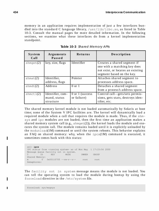
434 Interprocess Communication
memory in an application requires implementation of just a few interfaces bun-dled into the standard C language library, /usr/lib/libc.so , as listed in Table10-3. Consult the manual pages for more detailed information. In the followingsections, we examine what these interfaces do from a kernel implementationstandpoint.
The shared memory kernel module is not loaded automatically by Solaris at boottime; none of the System V IPC facilities are. The kernel will dynamically load arequired module when a call that requires the module is made. Thus, if the shm-sys and ipc modules are not loaded, then the first time an application makes ashared memory system call (e.g., shmget (2)), the kernel loads the module and exe-cutes the system call. The module remains loaded until it is explicitly unloaded bythe modunload (1M) command or until the system reboots. This behavior explainsan FAQ on shared memory: why, when the ipcs (1M) command is executed, itsometimes comes back with this status:
The facility not in system message means the module is not loaded. Youcan tell the operating system to load the module during bootup by using theforceload directive in the /etc/system file.
Table 10-3 Shared Memory APIs
SystemCall
ArgumentsPassed
Returns Description
shmget (2) key, size, flags Identifier Creates a shared segment ifone with a matching key doesnot exist, or locates an existingsegment based on the key.
shmat (2) Identifier,address, flags
Pointer Attaches shared segment toprocesses address space.
shmdt (2) Address 0 or 1 Detaches a shared segmentfrom a process’s address space.
shmctl (2) Identifier, com-mand, statusstructure
0 or 1 (successor failure)
Control call—gets/sets permis-sions, gets stats, destroys iden-tifier, etc.
se1> ipcsIPC status from <running system> as of Mon May 1 17:15:56 2000Message Queue facility not in system.T ID KEY MODE OWNER GROUPShared Memory:m 0 0x50110705 --rw-r--r-- root rootSemaphores:
forceload: sys/msgsys
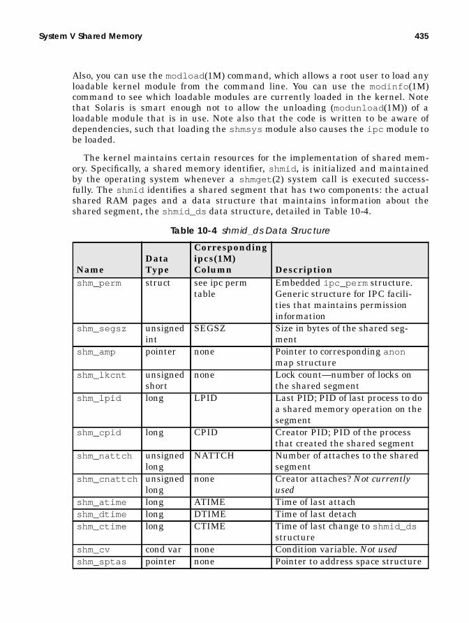
System V Shared Memory 435
Also, you can use the modload (1M) command, which allows a root user to load anyloadable kernel module from the command line. You can use the modinfo (1M)command to see which loadable modules are currently loaded in the kernel. Notethat Solaris is smart enough not to allow the unloading (modunload (1M)) of aloadable module that is in use. Note also that the code is written to be aware ofdependencies, such that loading the shmsys module also causes the ipc module tobe loaded.
The kernel maintains certain resources for the implementation of shared mem-ory. Specifically, a shared memory identifier, shmid , is initialized and maintainedby the operating system whenever a shmget (2) system call is executed success-fully. The shmid identifies a shared segment that has two components: the actualshared RAM pages and a data structure that maintains information about theshared segment, the shmid_ds data structure, detailed in Table 10-4.
Table 10-4 shmid_ds Data Structure
NameDataType
Correspondingipcs(1M)Column Description
shm_perm struct see ipc permtable
Embedded ipc_perm structure.Generic structure for IPC facili-ties that maintains permissioninformation
shm_segsz unsignedint
SEGSZ Size in bytes of the shared seg-ment
shm_amp pointer none Pointer to corresponding anonmap structure
shm_lkcnt unsignedshort
none Lock count—number of locks onthe shared segment
shm_lpid long LPID Last PID; PID of last process to doa shared memory operation on thesegment
shm_cpid long CPID Creator PID; PID of the processthat created the shared segment
shm_nattch unsignedlong
NATTCH Number of attaches to the sharedsegment
shm_cnattch unsignedlong
none Creator attaches? Not currentlyused
shm_atime long ATIME Time of last attachshm_dtime long DTIME Time of last detachshm_ctime long CTIME Time of last change to shmid_ds
structureshm_cv cond var none Condition variable. Not usedshm_sptas pointer none Pointer to address space structure

436 Interprocess Communication
The system allocates kernel memory for some number of shmid_ds structures atboot time, as determined from the shared memory tunable parameter shmmni . Alltogether, only four tunable parameters are associated with shared memory. Theyare described in Table 10-5.
When the system first loads the shared memory module, it allocates kernel mem-ory to support the shmid_ds structures and other required kernel support struc-tures. Each shmid_ds structure is 112 bytes in size and has a correspondingkernel mutex lock, which is an additional 8 bytes. Thus, the amount of kernelmemory required by the system to support shared memory can be calculated as((shmmni * 112) + (shmmni * 8)) . The default value of 100 for shmmnirequires the system to allocate 112.8 Kbytes of kernel memory for shared memorysupport. The system makes some attempt to protect itself against allocating toomuch kernel memory for shared memory support by checking for the maximumavailable kernel memory, dividing that value by 4, and using the resulting value asa limit for allocating resources for shared memory. Simply put, the system will notallow more than 25 percent of available kernel memory be allocated.
The preceding description applies to Solaris 2.5, 2.5.1, and 2.6. Prior releases,up to and including Solaris 2.4, did not impose a 25 percent limit check. Nor didthey require the additional 8 bytes per shmid_ds for a kernel mutex lock, sinceshared memory used very coarse grained locking in the earlier releases and onlyimplemented one kernel mutex in the shared memory code. Beginning in Solaris2.5, finer-grained locking was implemented, allowing for greater potential parallel-ism of applications using shared memory.
It should be clear that one should not set shmmni to an arbitrarily large valuesimply to ensure sufficient resources. There are limits as to how much kernelmemory the system supports. On sun4m-based platforms, the limits are on theorder of 128 Mbytes for releases prior to Solaris 2.5, and 256 Mbytes for Solaris2.5, 2.5.1, and 2.6. On sun4d systems (SS1000 and SC2000), the limits are about576 Mbytes in Solaris 2.5 and later. On UltraSPARC- (sun4u) based systems, the
Table 10-5 Shared Memory Tunable Parameters
NameDefaultValue
Minimum Value
MaximumValue
DataType Description
shmmax 1048576 1 4,294,967,295(4 GB)
unsignedint
Maximum size inbytes of a sharedmemory segment
shmmin 1 1 4,294,967,295(4 GB)
unsignedint
Minimum size for ashared segment
shmmni 100 1 2147483648(2 GB)
int Maximum number ofshmid_ds structures,systemwide.
shmseg 6 1 32767 (32K) short Max segments perprocess

System V Shared Memory 437
kernel has its own 4-Gbyte address space, so it is much less constrained. Still, keepin mind that the kernel is not pageable, and thus whatever kernel memory isneeded remains resident in RAM, reducing available memory for user processes.Given that Sun ships systems today with very large RAM capacities, this charac-teristic of the kernel may not be an issue, but it should be considered nonetheless.
Note that the maximum value for shmmni listed in Table 10-5 is 2 Gbytes. Thisis a theoretical limit, based on the data type (a signed integer), and should not beconstrued as something configurable today. Applying the math from above, you seethat 2 billion shared memory identifiers would require over 200 Gbytes of kernelmemory! Assess to the best of your ability the number of shared memory identifi-ers required by the application, and set shmmni to that value plus 10 percent or sofor headroom.
The remaining three shared memory tunable parameters are defined quite sim-ply.
shmmax defines the maximum size a shared segment can be. The size of ashared memory segment is determined by the second argument to the shmget (2)system call. When the call is executed, the kernel checks to ensure that the sizeargument is not greater than shmmax. If it is, an error is returned. Setting shm-max to its maximum value does not affect the kernel size—no kernel resources areallocated on the basis of shmmax, so this variable can be tuned to its maximumvalue of 4 Gbytes (0xffffffff) on a 32-bit Solaris system, and larger on a 64-bitSolaris 7 system. The /etc/system entry examples that follow illustrate twoways of setting the 4-Gbyte limit for a 32-bit system and setting something largeron a 64-bit Solaris 7 system, in this case, a 10-Gbyte maximum shared segment.
The shmmin tunable defines the smallest possible size a shared segment can be, asper the size argument passed in the shmget (2) call. There’s no compelling reasonto set this tunable from the default value of 1.
Lastly, shmseg defines the number of shared segments a process can attach(map pages) to. Processes can attach to multiple shared memory segments forapplication purposes, and this tunable determines how many mapped shared seg-ments a process can have attached at any one time. Again, the 32-Kbyte limit(maximum size) in Table 10-5 is based on the data type (short) and does not neces-sarily reflect a value that will provide application performance that meets busi-ness requirements if some number of processes attach to 32,000 shared memorysegments. Things like shared segment size, system size (amount of RAM, numberand speed of processors, etc.) all factor in to determining the extent to which youcan push the boundaries of this facility.
set shmsys:shminfo_shmmax=0xffffffff /* hexadecimal - 4GB limit */set shmsys:shminfo_shmmax=4294967295 /* decimal - 4GB limit */set shmsys:shminfo_shmmax=10000000000 /* decimal - 10GB, 64-bit example */

438 Interprocess Communication
10.2.1 Shared Memory Kernel Implementation
In this section we look at the flow of kernel code that executes when the sharedmemory system calls are called.
Applications first call shmget (2), to get a shared memory identifier. The kerneluses a key value passed in the call to locate (or create) a shared segment.
shmget() , when entered, calls ipcget() to fetch the shmid_ds data structure.Remember, all possible shmid_ds structures are allocated up-front when /ker-nel/sys/shmsys loads, so we need to either find an existing one that matches thekey value or initialize an unallocated one if the flags indicate we should and astructure is available. The final init phase of ipcget() sets the mode bits, creatorUID, and creator GID. When ipcget() returns to shmget() , the anon page map-pings are initialized for a new segment or a simple size check is done. (The size
[application code]shmget(key, size, flags [PRIVATE or CREATE])
[kernel]shmget() ipcget() /* get an identifier - shmid_ds */ if (new shared segment) check size against min and max tunables get anon_map and anon array structures initialize anon structures initialize shmid_ds structure else /* existing segment */ check size against existing segment size return shmid (or error) back to applicationipcget() if (key == IPC_PRIVATE) loop through shmid_ds structures, looking for a free one if (found) goto init else return ENOSPC /* tough cookies */ else /* key is NOT IPC_PRIVATE */ loop through shmid_ds structures, for each one if (structure is allocated) if (the key matches) if (CREATE or EXCLUSIVE flags set as passed args)
return EEXIST error /* segment with matching keyexists */ if (permissions do NOT allow access) return EACCESS error set status set base address of shmid_ds return 0 /* that’s a good thing */
set base address of shmid_ds /* if we reach this, we have an unallocated shmid_dsstructure */ if (do not CREATE) return ENOENT error /*we’re through them all, and didn’t match keys */ if (CREATE and no space) return ENOSPC error do init return 0 /* goodness */

System V Shared Memory 439
argument is the argument passed in the shmget (2) call, not the size of the exist-ing segment.)
Once a shmget (2) call returns success to an application, the code has a validshared memory identifier. The program must call shmat (2) to create the mappings(attach) to the shared segment.
Much of the work done in shmat() requires calls into the lower-level addressspace support code and related memory management routines. The details on aprocess’s address space mappings are covered in Chapter 10. Remember, attach-ing to a shared memory segment is essentially just another extension to a pro-cess’s address space mappings.
At this point, applications have a pointer to the shared segment that they use intheir code to read or write data. The shmdt (2) interface allows a process to unmapthe shared pages from its address space (detach itself). Unmapping does not causethe system to remove the shared segment, even if all attached processes havedetached themselves. A shared segment must be explicitly removed by the shm-ctl (2) call with the IPC_RMID flag set or from the command line with theipcrm (1) command. Obviously, permissions must allow for the removal of theshared segment.
We should point out that the kernel makes no attempt at coordinating concur-rent access to shared segments. The software developer must coordinate thisaccess by using shared memory to prevent multiple processes attached to the sameshared pages from writing to the same locations at the same time. Coordinationcan be done in several ways, the most common of which is the use of another IPCfacility, semaphores, or mutex locks.
[application]shmat(shmid, address, flags)
[kernel]shmat() ipc_access() /* check permissions */ /* ipc_access() will return EACCESS if permission tests fail */ /* and cause shmat() to bail out */ if (kernel has ISM disabled) clear SHM_SHARE_MMU flag if (ISM and SHM_SHARE_MMU flag) calculate number pages find a range of pages in the address space and set address if (user-supplied address) check alignment and range map segment to address create shared mapping tables if (NOT ISM) if (no user-supplied address) find a range of pages in the address space and set address else check alignment and rangereturn pointer to shared segment, or error
440 Interprocess Communication
The shmctl (2) interface can also be used to get information about the sharedsegment (returns a populated shmid_ds structure), to set permissions, and to lockthe segment in memory (processes attempting to lock shared pages must have aneffective UID of root).
You can use the ipcs (1) command to look at active IPC facilities in the system.When shared segments are created, the system maintains permission flags simi-lar to the permission bits used by the file system. They determine who can readand write the shared segment, as specified by the user ID (UID) and group ID(GID) of the process attempting the operation. You can see extended informationon the shared segment by using the -a flag with the ipcs (1) command. The infor-mation is fairly intuitive and is documented in the ipcs (1) manual page. We alsolisted in Table 10-4 on page 435 the members of the shmid_ds structures that aredisplayed by ipcs (1) output and the corresponding column name. The permis-sions (mode) and key data for the shared structure are maintained in theipc_perm data structure, which is embedded (a member of) the shmid_ds struc-ture and described in Table 10-2 on page 431.
10.2.2 Intimate Shared Memory (ISM)
Intimate shared memory (ISM) is an optimization introduced first in Solaris 2.2. Itallows for the sharing of the translation tables involved in the virtual-to-physicaladdress translation for shared memory pages, as opposed to just sharing the actualphysical memory pages. Typically, non-ISM systems maintain a per-process map-ping for the shared memory pages. With many processes attaching to shared mem-ory, this scheme creates a lot of redundant mappings to the same physical pagesthat the kernel must maintain.
Additionally, all modern processors implement some form of a TranslationLookaside Buffer (TLB), which is (essentially) a hardware cache of address trans-lation information. SPARC processors are no exception, and the TLB, just like aninstruction and data cache, has limits as to how many translations it can main-tain at any one time. As processes are context-switched in and out, we can reducethe effectiveness of the TLB. If those processes are sharing memory and we canshare the memory mappings also, we can make more effective use of the hardwareTLB.
Figure 10.1 illustrates the difference between ISM and non-ISM shared seg-ments.

System V Shared Memory 441
Figure 10.1 Shared Memory: ISM versus Non-ISM
The actual mapping structures differ across processors. UltraSPARC (SPARC V9)processors implement Translation Tables, consisting of Translation Table Entries(TTEs). SuperSPARC (SPARC V8) systems implement Page Tables, which containPage Table Entries (PTE). They both do essentially the same thing: provide ameans of mapping virtual to physical addresses. However, the two SPARC archi-tectures differ substantially in MMU (Memory Management Unit) implementa-tion. (The MMU is the part of the processor chip dedicated to the addresstranslation process.) SPARC V8 defines the SPARC Reference MMU (SRMMU)and provides implementation details. SPARC V9 does not define an MMU imple-mentation, but rather provides some guidelines and boundaries for chip designersto follow. The actual MMU implementation is left to the chip design folks. Addi-tionally, a significant amount of kernel code (such as the creation and manage-ment of the translation tables) is dedicated to the address translation process.
physicalmemory
shared segmentmemory pages
process A
process B
process C
translationtables
translationtables
translationtables
shar
ed m
emor
y re
fere
nces
.vi
rtua
l add
ress
gen
erat
ed
physical memoryaddresses
physicalmemory
shared segmentmemory pages
process A
process B
process C
translationtables
physical memoryaddresses
A non-ISM shared segment
An ISM shared segment
shared translationtables

442 Interprocess Communication
Let’s consider just one simple example. A database system uses shared memoryfor caching various database objects, such as data, stored procedures, indexes, etc.All commercial database products implement a caching mechanism that usesshared memory. Assume a large, 2-Gbyte shared segment is configured and thereare 400 database processes, each attaching to the shared segment. Two gigabytesof RAM equates to 262,144 eight-kilobyte pages. Assuming that the kernel needsto maintain 8 bytes of information for each page mapping (two 4-byte pointers),that’s about 2 Mbytes of kernel space needed to hold the translation informationfor one process. Without ISM, those mappings are replicated for each process, somultiply the number times 400, and we now need 800 Mbytes of kernel space justfor those mappings. With ISM, the mappings are shared, so we only need the 2Mbytes of space, regardless of how many processes attach.
In addition to the translation table sharing, ISM provides another useful fea-ture: when ISM is used, the shared pages are locked down in memory and willnever be paged out. This feature was added for the RDBMS vendors. As we saidearlier, shared memory is used extensively by commercial RDBMS systems tocache data (among other things, such as stored procedures). Non-ISM implementa-tions treat shared memory just like any other chunk of anonymous memory—itgets backing store allocated from the swap device, and the pages themselves arefair game to be paged out if memory contention becomes an issue. The effects ofpaging out shared memory pages that are part of a database cache would be disas-trous from a performance standpoint—RAM shortages are never good for perfor-mance. Since a vast majority of customers that purchase Sun servers use them fordatabase applications and since database applications make extensive use ofshared memory, addressing this issue with ISM was an easy decision.
Solaris implements memory page locking by setting some bits in the memorypage’s page structure. Every page of memory has a corresponding page structurethat contains information about the memory page. Page sizes vary across differenthardware platforms. UltraSPARC based systems implement an 8-Kbyte memorypage size, which means that 8 Kbytes is the smallest unit of memory that can beallocated and mapped to a process’s address space.
The page structure contains several fields, among which are two fields calledp_cowcnt and p_lckcnt , that is, page copy-on-write count and page lock count.Copy-on-write tells the system that this page can be shared as long as it’s beingread, but once a write to the page is executed, the system is to make a copy of thepage and map it to the process that is doing the write. Lock count maintains acount of how any times page locking was done for this page. Since many processescan share mappings to the same physical page, the page can be locked from sev-eral sources. The system maintains a count to ensure that processes that completeand exit will not result in the unlocking of a page that has mappings from otherprocesses. The system’s pageout code, which runs if free memory gets low, checksthe status to the pages p_cowcnt and p_lckcnt fields. If either of these fields isnonzero, the page is considered locked in memory and thus not marked as a candi-date for freeing. Shared memory pages using the ISM facility do not use the

System V Shared Memory 443
copy-on-write lock (that would make for a nonshared page after a write). Pageslocked through ISM implement the p_lckcnt page structure field.
Even though ISM locks pages in memory so that they’ll never be paged out,Solaris still treats ISM shared segments the same way it treats non-ISM sharedsegments and other anonymous memory pages: it ensures that there is sufficientbacking store in swap before completing the page mapping on behalf of therequesting process. While this seems superfluous for ISM pages (allocating diskswap space for pages that can’t be swapped out), it made the implementationcleaner. Solaris 2.6 changes this somewhat, and in Solaris 2.6 swap is not allo-cated for ISM pages. The net effect is that allocation of shared segments using ISMrequires sufficient available swap space for the allocation to succeed, at least untilSolaris 2.6. Using ISM requires setting a flag in the shmat (2) system call. Specifi-cally, the SHM_SHARE_MMUflag must be set in the shmflg argument passed in theshmat (2) call, to instruct the system to set up the shared segment as intimateshared memory. Otherwise, the system will create the shared segment as anon-ISM shared segment.
In Solaris releases up to and including Solaris 7, there is not an easy way to tellwhether or not a shared segment is an ISM shared segment. It can be done butrequires root permission and use of the crash (1M) utility.
In the example below, we start a program called shm1, which creates andattaches to a 1-Mbyte shared segment, and we use a key value of 10 (the com-mand-line arguments). The program prints the process virtual address of theshared segment and touches all the pages in the shared segment, printing a mes-sage indicating how many bytes have been touched. The test program then justsits in a loop, doing nothing.
The PID of the test process is 20179. The crash (1M) utility is started, and the pfunction dumps the process table (most of the table output is deleted). The processis located in table slot 73, as verified with the p 73 command. Finally, a full list-ing of the address space is dumped with the as -f command.
Looking at the address space listing, matching the address of the shared seg-ment, ed000000, we can determine which segment driver is used for that addressspace segment. In this case, the segment driver is the segspt_shm driver, which isa driver specifically for ISM shared memory. Any address space segment mappedthat shows this segment driver is an ISM segment. If the mapping represents a

444 Interprocess Communication
shared segment that is not an ISM segment, the segment driver will be the stan-dard segvn_ops driver.
10.3 System V Semaphores
A semaphore, as defined in the dictionary, is a mechanical signalling device or ameans of doing visual signalling. The analogy typically used is the railroad mecha-nism of signalling trains, where mechanical arms would swing down to block atrain from a section of track that another train was currently using. When thetrack was free, the arm would swing up, and the waiting train could then proceed.
The notion of using semaphores as a means of synchronization in computer soft-ware was originated by a Dutch mathematician, E. W. Dijkstra, in 1965. Dijkstra’s
# shm1 1048576 10 &[1] 20179sunsys>Attached, shmptr: ed000000touching pagesbytes touched: 1048576sunsys> su# /etc/crashdumpfile = /dev/mem, namelist = /dev/ksyms, outfile = stdout> pPROC TABLE SIZE = 4058SLOT ST PID PPID PGID SID UID PRI NAME FLAGS 0 t 0 0 0 0 0 96 sched load sys lock 1 s 1 0 0 0 0 58 init load . . . 72 z 19821 5234 19821 19821 0 99 zombie load 73 r 20179 533 20179 533 19821 0 shm1 load 74 s 17199 490 17199 490 0 45 sh load 75 z 19809 5234 19809 19809 0 99 zombie load 79 s 20180 533 20180 533 0 54 sh load> p 73PROC TABLE SIZE = 4058SLOT ST PID PPID PGID SID UID PRI NAME FLAGS 73 p 20179 533 20179 533 19821 0 shm1 load> as -f 73
PROC PAGLCK CLGAP VBITS HAT HRM RSS SEGLST LOCK SEGS SIZE LREP TAIL NSEGS 73 0 0 0x0 0xf59cfb58 0x00xf69af3c0 0xefffed58 0xf69775a0 17563648 0 0xf69afb20 11 BASE SIZE AS NEXT PREV OPS DATA 0x00010000 2000 0xf591eba0 0xf65d4500 0x00000000 segvn_ops 0xf69b9d68 0x00021000 1000 0xf591eba0 0xf69aff20 0xf69775a0 segvn_ops 0xf65f1288 0xed000000 1000000 0xf591eba0 0xf69af3c0 0xf65d4500 segspt_shm 0xf653a480 0xef700000 93000 0xf591eba0 0xf69afb40 0xf69aff20 segvn_ops 0xf65d1a60 . . . 0xefffe000 2000 0xf591eba0 0x00000000 0xf69aff00 segvn_ops 0xf69a4dd0

System V Semaphores 445
original work defined two semaphore operations, wait and signal (which correlatenicely to the railroad example). The operations were referred to as P and V opera-tions. The P operation was the wait, which decremented the value of the sema-phore if it was greater than zero, and the V operation was the signal, whichincremented the semaphore value. The terms P and V originate from the Dutchterms for try and increase. P is from Probeer, which means try or attempt, and V isfrom Verhoog, which means increase. P(robeer) decreases the semaphore count andV(erhoog) increases the count. (Thanks to [email protected] for sharing that bit of trivia with us.)
Semaphores provide a method of synchronizing access to a sharable resource bymultiple processes. They can be used as a binary lock for exclusive access or as acounter; they manage access to a finite number of shared resources, where thesemaphore value is initialized to the number of shared resources. Each time a pro-cess needs a resource, the semaphore value is decremented. When the process isdone with the resource, the semaphore value is incremented. A zero semaphorevalue conveys to the calling process that no resources are currently available, andthe calling process blocks until another process finishes using the resource andfrees it.
The semaphore implementation in Solaris (System V semaphores) allows forsemaphore sets, meaning that a unique semaphore identifier can contain multiplesemaphores. Whether a semaphore indentifier contains one semaphore or a set ofsemaphores is determined when the semget (2) system call creates the sema-phore. The second argument to semget (2) determines the number of semaphoresthat will be associated with the semaphore identifier returned by semget (2). Thesemaphore system calls allow for some operations on the semaphore set, such thatthe programmer can make one semctl (2) or semop(2) system call and touch allthe semaphores in the semaphore set. This approach makes dealing with sema-phore sets programmatically a little easier.
10.3.1 Semaphore Kernel Resources
The tunable kernel parameters that apply to semaphores are summarized in Table10-6. We next take a closer look at each one and discuss how kernel resources areallocated.
Table 10-6 Semaphore Kernel Tunables
NameDefaultValue
MaximumValue
DataType Description
semmap 10 2 billion signedint
Size of semaphore resourcemap
semmni 10 65536 signedint
Number of semaphore iden-tifiers
semmns 60 2 billion signedint
Total semaphores, system-wide

446 Interprocess Communication
• semmap— Determines the maximum number of entries in a semaphore map.The memory space given to the creation of semaphores is taken from thesemmap, which is initialized with the number of map entries fixed by thevalue of semmap. The implementation of allocation maps is generic withinUNIX SVR4 and Solaris, supported with a standard set of kernel routines(rmalloc() , rmfree() , etc.).The use of allocation maps by the semaphore subsystem is just one exampleof their implementation. They basically prevent the kernel from having todeal with allocating and deallocating additional kernel memory as sema-phores are initialized and freed. By initialization and use of allocation maps,kernel memory is allocated up-front, and map entries are allocated and freeddynamically from the semmapallocation maps. Given that semmns limits thetotal number of semaphores systemwide and that semaphore space is allo-cated from the resource map, it makes sense to set semmap equal to semmns.
• semmni — Establishes the maximum number of systemwide semaphore sets.Every semaphore set in the system has a unique identifier and control struc-ture, the semid_ds data structure. During init, the system allocates kernelmemory for semid_ds control structures as determined from the semmnitunable. Each control structure is 84 bytes, so as with the shared memoryshmmni tunable, you should avoid making this value arbitrarily large.
• semmns — Defines the maximum number of semaphores in the system. Asemaphore set can have more than one semaphore associated with it, andeach semaphore has a corresponding sem data structure. Each sem structureis only 16 bytes, but you still shouldn’t go over the edge with this (do not
semmnu 30 2 billion signedint
Total undo structures, sys-temwide
semmsl 25 65536 unsigned short
Maximum number sema-phores per identifier
semopm 10 2 billion signedint
Maximum operations persemop(2) call
semume 10 2 billion signedint
Maximum undo entries perprocess
semusz 96 2 billion signedint
Total bytes required forundo structures, system-wide
semvmx 32767 65536 unsigned short
Maximum value of a sema-phore
semaem 16384 32767 signedshort
Maximum adjust on exitvalue
Table 10-6 Semaphore Kernel Tunables (Continued)
NameDefaultValue
MaximumValue
DataType Description

System V Semaphores 447
make it arbitrarily a very large value). Actually, this number should really becalculated as semmns = semmni × semmsl . Since semmsl defines the maxi-mum number of semaphores per semaphore set and semmni defines the max-imum number of semaphore sets, the total number of semaphoressystemwide can never be greater than the product of semmni and semmsl .semmns and semmap should be the same value.
• semmnu — Defines the systemwide maximum number of semaphore undostructures. Semaphore undo structures are maintained in the event of termi-nation of a process that has made some semaphore value adjustments. If theSEM_UNDObit is true in the semaphore flag value (sem_flg ) when the sema-phore operation is done (the semop(2) system call), then the kernel undoeschanges made to the semaphore(s) when the process terminates. Seems intui-tive to make this equal to semmni , which would provide for an undo struc-ture for every semaphore set. Each semaphore undo structure is 16 bytes.
• semmsl — Maximum number of semaphores per semaphore set. Each sema-phore set can have one or more semaphores associated with it; this tunabledefines the maximum number per set.
• semopm — Maximum number of semaphore operations that can be per-formed per semop(2) call. This tunable takes us back to the notion of sema-phore sets and the ability to do operations on multiple semaphores by meansof the semop(2) system call. The semaphores in the set will all be associatedwith the same semaphore ID (semid_ds structure). You should probably setthis value equal to semmsl so you’ll always be able to do an operation onevery semaphore in a semaphore set.When a semop(2) call is executed, the kernel checks to ensure that the thirdargument to semop(2), which is the size of the semaphore set array, is notlarger than the semopm tunable. If it is, an error is returned to the callingcode.
• semume— Determines the maximum allowable per process undo structures,or, put another way, the maximum number of semaphore undo operationsthat can be performed per process. The kernel maintains information onchanges that processes make to semaphores (semaphore value adjustments).In the event of a process exiting prematurely, the kernel can set the sema-phore values back to what they were before the process changed them. This iswhat undo structures are used for: to undo semaphore alterations in theevent of abnormal process termination.
• semusz — Size in bytes for undo structures. We don’t know why this is evendocumented as a tunable. During initialization of the semaphore code, thekernel sets semusz to (sizeof(undo) + (semume × sizeof(undo)) , sosetting it in /etc/system is pointless. Leave it alone; it should be removedas a tunable.
448 Interprocess Communication
• semvmx — Maximum value of a semaphore. Because of the interaction withundo structures and semaem (more details below), this tunable should notexceed a maximum of its default value of 32767 unless you can guaranteethat SEM_UNDOis never being used. The actual value of a semaphore is storedas an unsigned short (2 bytes) in its semaphore structure, implying that themaximum semaphore value can be 65535 (64 Kbytes), the maximum value ofan unsigned short data type. The next bullet explains why the limit shouldreally be 32767.
• semaem— Maximum adjust-on-exit value. This value is stored as an integerin the seminfo structure that the kernel uses to maintain the tunable val-ues, but it is implemented as a signed short in the undo structure. It needs tobe signed because semaphore operations can increment or decrement thevalue of a semaphore, and thus the system might need to apply a negative orpositive adjustment value to the semaphore to do a successful adjust-on-exitoperation.The actual value of a semaphore can never be negative. The maximum valuefor a signed short, which is 2 bytes (16 bits), is 32767 (32 Kbytes). If semvmxwere set to 65535 and the application actually set semaphore values thathigh, the system would not be able to undo the entire range of semaphorevalue changes, because semaemcan never be greater than 32767. This is whysemvmx should never be greater than 32767, unless you don’t care about undooperations.
10.3.2 Kernel Implementation of System V Semaphores
During initialization of the semaphore code, when /kernel/sys/semsys is firstloaded, the value of semmni is checked to ensure it is not greater than the maxi-mum allowable value of 65536 (64 Kbytes). If it is, it gets set to 65536 and a con-sole message is printed stating that the value of semmni was too large. Followingthat, the tunable parameters, with the exception of semusz , from the /etc/sys-tem file are plugged into the internal seminfo data structure.
Just as with shared memory, the system checks for the maximum amount ofavailable kernel memory and divides that number by 4, to prevent semaphorerequirements from taking more than 25 percent of available kernel memory.Actual memory requirements for semaphores are calculated as follows.
The structure sizes are given in the previous section. Pointers and integers are 4bytes, and a kernel mutex is 8 bytes. The maximum process value is determined
total_kernel_memory_required = (semmns * (sem structure size)) + (semmni * (semid_ds structure size)) + (semmni * (kernel mutex size)) + (max_nprocs * (undo structure size)) + (semusz * semmnu * (integer size))

System V Semaphores 449
during startup and is based on the amount of RAM in the system. You can deter-mine the actual value on your system with the sysdef (1M) command.
Doing the actual arithmetic is left as an exercise for the reader. If the requiredmemory is more than 25 percent of available kernel memory, a message so statingis displayed on the console.
Assuming everything fits, kernel memory is allocated as follows. Resource mapallocation is done, based on semmap, and a kernel semmappointer is set. Space isallocated for the following:
• All the sem structures (one for every semaphore); based on semmns
• All the semaphore identifiers (semid_ds ); based on the size of that structure
• All the undo structure pointers; based on the max processes and pointer size
• All the undo structures themselves; based on semmnuand the size of an undostructure
• All the kernel mutex locks required, one for every unique semaphore identi-fier; based on semmni and the size of a kernel mutex
A kernel mutex lock is created for each semaphore set. This practice results infairly fine grained parallelism on multiprocessor hardware, since it means thatmultiple processes can do operations on different semaphore sets concurrently. Foroperations on semaphores in the same set, the kernel needs to ensure atomicity forthe application. Atomicity guarantees that a semaphore operation initiated by aprocess will complete without interference from another process, whether the oper-ation is on a single semaphore or multiple semaphores in the same set.
# sysdef | grep v_proc1962 maximum number of processes (v.v_proc)

450 Interprocess Communication
10.3.3 Semaphore Operations Inside Solaris
The creation of a semaphore set by an application requires a call to semget (2).Every semaphore set in the system is described by a semds_id data structure,which contains the following elements.
The system checks to see if a semaphore already exists by looking at the key valuepassed to semget (2) and checks permissions by using the ipc support routine,ipcaccess() . Semaphore permissions differ slightly from permission modeswe’re used to seeing in things like Solaris files. They’re defined as READ andALTER, such that processes can either read the current semaphore value or alter it(increment/decrement). Permissions are established with arguments passed to thesemget (2) call, following the owner, group, and other conventions used for Solarisfile permissions.
Assuming a new semaphore, space is allocated from the resource map pool asneeded for the number of semaphores in the set requested, and the elements in thesemid_ds data structure are initialized, with the sem_base pointer being set topoint to the first semaphore in the set.
Once the semaphore is created, typically the next step is initializing the sema-phore values. Initialization is done with the semctl (2) call, using either SETVALtoset the value of each semaphore in the set one at a time (or if there is but onesemaphore in the set) or SETALL to set the value of all the semaphores in the setin one operation. The actual kernel flow is relatively straightforward, with theexpected permission and value checks against the maximum allowable values, andthe setting of the user-defined values if everything checks out.
Actual semaphore use by application code involves the semop(2) system call.semop(2) takes the semaphore ID (returned by semget (2)), a pointer to a sembuf
/* * There is one semaphore id data structure (semid_ds) for each set of * semaphores in the system. */
struct semid_ds { struct ipc_perm sem_perm; /* operation permission struct */ struct sem *sem_base; /* ptr to first semaphore in set */ ushort_t sem_nsems; /* # of semaphores in set */ time_t sem_otime; /* last semop time */ long sem_pad1; /* reserved for time_t expansion */ time_t sem_ctime; /* last change time */ long sem_pad2; /* time_t expansion */ long sem_binary; /* flag indicating semaphore type */ long sem_pad3[3]; /* reserve area */};
Header File <sys/sem.h>

System V Message Queues 451
structure, and the number of semaphore operations as call arguments. The sem-buf structure contains the following elements.
The programmer must create and initialize the sembuf structure, setting thesemaphore number (specifying which semaphore in the set), the operation (moreon that in a minute), and the flag. The value of sem_op determines whether thesemphore operation will alter or read the value of a semaphore. A nonzero sem_opvalue either negatively or positively alters the semaphore value. A zero sem_opvalue will simply do a read of the current semaphore value.
The semop(2) manual page contains a fairly detailed flow in the DESCRIPTIONsection on what the operation will be for a given sem_op value and a given flagvalue.
10.4 System V Message Queues
Message queues provide a means for processes to send and receive messages ofvarious size in an asynchronous fashion on a Solaris system. As with the other IPCfacilities, the initial call when message queues are used is an ipcget call, in thiscase, msgget (2). The msgget (2) system call takes a key value and some flags asarguments and returns an identifier for the message queue. Once the messagequeue has been established, it’s simply a matter of sending and receiving mes-sages. Applications use msgsnd(2) and msgrcv (2) for those purposes. The sendersimply constructs the message, assigns a message type, and calls msgsnd(2). Thesystem will place the message on the appropriate message queue until amsgrcv (2) is successfully executed. Sent messages are placed at the back of thequeue, and messages are received from the front of the queue; thus the queue isimplemented as a FIFO (First In, First Out).
The message queue facility implements a message type field, which is user (pro-grammer) defined. So, programmers have some flexibility, since the kernel has noembedded or predefined knowledge of different message types. Programmers typi-cally use the type field for priority messaging or directing a message to a particu-lar recipient.
Lastly, applications use the msgctl (2) system call to get or set permissions onthe message queue and to remove the message queue from the system when theapplication is finished with it. For example, msgct (2) offers a clean way to imple-
struct sembuf { ushort_t sem_num; /* semaphore # */ short sem_op; /* semaphore operation */ short sem_flg; /* operation flags */};
Header File <sys/sem.h>

452 Interprocess Communication
ment an application shutdown procedure, because the system will not remove anempty and unused message queue unless it is explicitly instructed to do so or thesystem is rebooted.
10.4.1 Kernel Resources for Message Queues
Like the IPC facilities previously discussed, the message queue facility comes inthe form of a dynamically loadable kernel module, /kernel/sys/msgsys , anddepends on the IPC support module, /kernel/misc/ipc , to be loaded in memory.
The number of resources that the kernel allocates for message queues is tun-able. Values for various message queue tunable parameters can be increased fromtheir default values so more resources are made available for systems runningapplications that make heavy use of message queues. Table 10-7 summarizes thetunable parameters and lists their default and maximum values.
• msgmap — Number of entries in the message map; essentially the same asthe semmapparameter used for semaphores. Both IPC facilities use resourceallocation maps in the kernel. A kernel resource map is simply an array ofmap structures used for the allocation and deallocation of segments of anaddress space. They provide a convenient means of managing small seg-ments of kernel memory where there is frequent allocation and deallocation,such as the case with message queues (and semaphores). The system grabsmessage map entries when it needs space to store new messages to place on amessage queue.
Table 10-7 Message Queue Tunable Parameters
Name Default MaxDataType Description
msgmap 100 2 billion signedint
Number of message map entries
msgmni 50 2 billion signedint
Maximum number of messagequeue identifiers
msgmax 2048 2 billion signedint
Maximum message size
msgmnb 4096 2 billion signedint
Maximum number of bytes on amessage queue
msgtql 40 2 billion signedint
Maximum number of messageheaders
msgssz 8 2 billion signedint
Maximum message segment size
msgseg 1024 32Kbytes
unsignedshort
Maximum number of messagesegments
System V Message Queues 453
• msgmni — Number of message queue identifiers. Like shared memory seg-ments and semaphores, message queues have an identifier associated withthem, with a corresponding ID data structure, the msqid_ds structure. Thevalue of msgmni determines the maximum number of message queues thekernel can maintain. As we’ll see below, the system allocates kernel memorybased on the value of msgmni , so don’t set this value arbitrarily high. Withluck, the system software engineers will have a sense for how many messagequeues are needed by the application and can set msgmni appropriately, add-ing 10 percent or so for headroom.
• msgmax — Maximum size a message can be, in bytes. The kernel does notallocate resources up-front on the basis of msgmax, but it is something thatthe application developer needs to be aware of. The the system will not allowmessages that have a size larger than msgmaxon the message queue and willreturn an error to the calling code, stating the message is too large.Even with a theoretical size limit of 2 Gbytes for the maximum message size,message queues are probably not the most efficient way to move large blocksof data between processes. If the data requirements are relatively large, soft-ware engineers should consider using shared memory instead of messagequeues for data sharing among processes. Or, programmers could use one ofthe more recent additions to Unix, such as a FIFO (named pipe). By morerecent, we mean recent relative to message queues—FIFOs have actuallybeen around for quite a while, but not as long as message queues.
• msgmnb — Maximum number of bytes on a message queue. Rephrased, thesum total of all the bytes of all the messages on the queue cannot exceedmsgmnb. When the message queue is initialized (the first msgget (2) call exe-cuted with the IPC_CREAT flag set), the kernel sets a member of themsgid_ds structure, the msg_qbytes field, to the value of msgmnb. Thisvalue makes the information available to programmers, who can usemsgctl (2) to retrieve the msgid_ds data. More importantly, code executedwith an effective UID of root (typically 0), can programmatically increase thisvariable, in case the queue needs to hold more message bytes than originallyallocated at boot time.If an application attempts to put a new message on a message queue that willresult in the total bytes being greater then msgmnb, the msgsnd(2) call eitherreturns an error or the process blocks, waiting for message to be pulled off thequeue, depending on whether the IPC_WAIT flag is true .
• msgtql — Maximum number of message headers. Each message on a mes-sage queue requires a message header, which is defined in the kernel by themsg structure (more on that in the next section). Basically, this tunableshould reflect the maximum number of messages (message queues times mes-sages per queue) the application will need, plus a little headroom.

454 Interprocess Communication
• msgssz — Maximum message segment size. Determines the maximum num-ber of message segments. msgseg is stored as a signed short data type in thekernel and thus cannot be greater then 32768 (32 Kbytes) bytes in size. Thekernel creates a pool of memory to hold the message data, and the size of thatpool is the product of msgssz and msgseg parameters. Described moreclearly: the number of units of allocation from the data space is msgseg, andthe size of each allocation unit from the space is msgssz .
• msgseg — As above, the number of units of space that can be allocated fromthe memory map segment described previously.
When the /kernel/sys/msgsys module is first loaded, an initialization routineexecutes. The routine does much the same sort of work that is done for sharedmemory and semaphore initialization. That is, it checks the amount of kernelmemory that will be required for resources, as determined by the tunable parame-ters. Then, provided the required amount is no greater than 25 percent of avail-able kernel memory, the system allocates the resources.
The amount of kernel memory required is calculated as follows.
In the next few paragraphs, we give you the sizes of the structures in bytes, andonce again the arithmetic with either the default or custom values is left as anexercise for the reader. The char data type on SPARC/Solaris systems is 1 byte insize.
The kernel sets several pointers in the message queue that will be referenced inthe subsequent text when the resources are initialized. An msg pointer is set topoint to the beginning of the pool of memory used to store message data, describedearlier. msgmap points to the beginning of the map structures used for maintain-ing resource allocation maps. A map structure is 8 bytes in size and contains thesize of the mapped segment and the base address.
kernel_memory_required = ((msgseg * msgssz) * sizeof char data type) + (msgmap * sizeof map structure) + (msgmni * sizeof msqds_id structure) + (msgtql * sizeof msg structure) + (msgmni * sizeof msglock structure)

System V Message Queues 455
The kernel data structure that describes each message queue is the msqid_dsstructure.
The preceding structure field descriptions are basically self-explanatory. The per-missions are established by the process that creates the shared segment, and theycan be changed with the msgctl (2) system call. The kernel pointer msgque pointsto the beginning of the kernel space allocated to hold all the system msqid_dsstructures. It is simply an array of msqid_ds structures, with msgque pointing tothe first structure in the array; the total number of structures in the array is equalto the msgmni tunable. Each structure is 112 bytes in size.
The messages in a message queue are maintained in a linked list, with the rootof the list in the msqid_ds data structure (the msg_first pointer), which pointsto the message header for the message. The kernel also maintains a linked list ofmessage headers, rooted in the kernel pointer.
The kernel message structure (actually, message header structure would be a moreaccurate name) is 12 bytes in size, an, as we said, one exists for every message onevery message queue (the msgtql tunable). The last chunk of kernel memory allo-cated is for the message queue synchronization locks. The method of synchroniza-tion is a condition variable protected by a mutex (mutual exclusion) lock, definedin the msglock structure, created for every message queue (one per messagequeue identifier).
struct msqid_ds { struct ipc_perm msg_perm; /* operation permission struct */ struct msg *msg_first; /* ptr to first message on q */ struct msg *msg_last; /* ptr to last message on q */ ulong msg_cbytes; /* current # bytes on q */ ulong msg_qnum; /* # of messages on q */ ulong msg_qbytes; /* max # of bytes on q */ pid_t msg_lspid; /* pid of last msgsnd */ pid_t msg_lrpid; /* pid of last msgrcv */ time_t msg_stime; /* last msgsnd time */ long msg_pad1; /* reserved for time_t expansion */ time_t msg_rtime; /* last msgrcv time */ long msg_pad2; /* time_t expansion */ time_t msg_ctime; /* last change time */ long msg_pad3; /* time expansion */ kcondvar_t msg_cv; kcondvar_t msg_qnum_cv; long msg_pad4[3]; /* reserve area */};
Header File <sys/msg.h>
struct msg { struct msg *msg_next; /* ptr to next message on q */ long msg_type; /* message type */ ushort_t msg_ts; /* message text size */ short msg_spot; /* message text map address */};
Header File <sys/msg.h>

456 Interprocess Communication
Condition variables are a means of allowing a process (thread) to test whether aparticular condition is true under the protection of a mutex lock. The mutexensures that the condition can be checked for atomically, and no other thread canchange the condition while the first thread is testing the condition. The thread willblock, holding the mutex until the condition changes state (becomes true ), atwhich point the thread can continue execution. A good example is a message on aqueue. If none exists, the thread blocks (sleeps) on the condition variable. When amessage appears on the queue, the system sends a broadcast and the thread isawakened, ready to pull the message off the queue.
A final note on kernel locking. All versions of the Solaris, up to and includingSolaris 2.5.1, do very coarse grained locking in the kernel message queue module.Specifically, one kernel mutex is initialized to protect the message queue kernelcode and data. As a result, applications running on multiprocessor platforms usingmessage queues do not scale well. This situation is changed in Solaris 2.6, whichimplements a finer-grained locking mechanism, allowing for greater concurrency.The improved message queue kernel module has been backported and is availableas a patch for Solaris 2.5 and 2.5.1.
Figure 10.2 illustrates the general layout of things after initialization of themessage queue module is complete, along with the kernel pointers describedabove.
Figure 10.2 System V Message Queue Structures
msg_permmsg_firstmsg_last
msg_permmsg_firstmsg_last
msg_permmsg_firstmsg_last
msg_permmsg_firstmsg_last
msgque
msg_nextmsg_spot
msg_nextmsg_spot
msg_nextmsg_spot
msg_nextmsg_spot
m_sizem_addr
m_sizem_addr
m_sizem_addr
m_sizem_addr
msg_nextmsg_spot
msg_nextmsg_spot
msg_nextmsg_spot
msgh
. . . . . . . . . . .
activ
e m
essa
ge h
eade
rs
pool of kernelmemory formessages
msgmap
free pool ofmessage headers
array ofmsqds_idstructures
msg_nextmsg_spot
m_sizem_addr

System V Message Queues 457
10.4.2 Kernel Implementation of Message Queues
We’ll walk through the kernel flow involved in the creation of a message queue andthe sending and receiving of messages, since these represent the vast majority ofmessage queue activities.
• The creation of a message on behalf of an application calling the msgget (2)system call starts with a call to the kernel ipcget() routine. An ipc_permstructure will be available for every message queue identifier (msgmni).
• Once a structure has been allocated, the system initializes the structuremembers as specified by the UID and GID of the calling process and the per-mission mode bits passed by the calling code, then sets the IPC_ALLOC bit tosignify the ipc_perm structure has been allocated. (The ipcget() code isthe same as illustrated previously—it’s the same function!—so we won’trevisit it here.)If ipcget() returns successfully, the application code has a valid messagequeue identifier, can send and receive messages, and can run message con-trol (msgctl (2)) operations.
A message send (msgsnd(2)) call requires the application to construct a message,setting a message type field and creating the body of the message (e.g., a text mes-sage).
• When the code path for the message send kernel support code is first entered,the code does some general housekeeping—such as incrementing the proces-sor statistics to announce a message queue system call is being executed. Thecpu_sysinfo structure maintains a msg counter that reflects the total num-ber of message queue system calls executed.
• The code verifies the calling process’s access permissions to the messagequeue and tests the message size against the msgmax tunable.
• Next, the code copies the message type field from the user address space to adesignated area in the kernel.

458 Interprocess Communication
The rest of the message send flow is best represented in pseudocode.
The msgrcv support code is a little less painful, since now we’re looking for a mes-sage on the queue (as opposed to putting one on the queue). Kernel resources donot need to be allocated for a msgrcv . The general flow of the kernel code path forreceiving messages involves checking permissions for operation in a loop throughall the messages on the queue.
• If the requested message type matches a message on the queue, the code cop-ies the message type to the user-supplied location and copies the messagedata to the user-supplied location.
• Next, the code updates the msqid_ds structure fields, subtracts the messagesize from msg_cbytes , sets PID in msg_lrpid , sets time in msg_rtime ,frees the message resources, frees the message header (msg structure), andfrees the resource map entry.
• If the code looped through all messages and found no matching type, itreturns a No Message error.
When the sequence is completed, the application code will have the message typeand data in a buffer area supplied in the msgrcv (2) system call.
The only remaining callable routine for applications to use is the msgctl (2) sys-tem call. The control functions are straightforward; they typically involve eitherretrieving or setting values in a message queue’s ipc_perm structure.
if (message queue no longer exists) return EIDRM errorif (current bytes on queue + bytes in new msg > msgmax) if (IPC_NOWAIT is set) return EAGAIN else set MSGWAIT flag in msqid_ds.msg_perm.mode call cv_wait_sig() /* put the caller to sleep until space is available on the queue *//* on wakeup, code will validate msqid, and set EDIRM if itUs been removed */ allocate space for message from resource map (msgmap) if (space not available) if (IPC_NOWAIT) return EAGAIN error else call cv_wait_sig() /* sleep waiting for space *//* once the wakeup is issued, the necessary resources are available for putting the message on the queue */ copy message data from user space to kernel space (map area) increment msqid_ds.qnum msqid_ds.msg_cbytes += new message size msqid_ds.mds_lspid = PID of caller msqid_ds.msg_stime = current time
update message header msg_type, msg_ts (text size) and msg_spot (map locationpointer) adjust the queue pointers (msg_first, msg_next, msg_last)return success to calling program

POSIX IPC 459
• When msgctl (2) is invoked with the IPC_RMID flag, meaning the callerwishes to remove the message queue from the system, the kernel walks thelinked list of messages on the queue, freeing up the kernel resources associ-ated with each message.
• The kernel sends a wakeup signal to processes (threads) sleeping on the mes-sage queue. The processes ultimately end up with an EIDRM error (IDremoved).
• The system simply marks the msqid_ds structure as being available, andreturns.
10.5 POSIX IPC
The evolution of the POSIX standard and associated application programminginterfaces (APIs) resulted in a set of industry-standard interfaces that provide thesame types of facilities as the System V IPC set: shared memory, semaphores, andmessage queues. They are quite similar in form and function to their System Vequivalents but very different in implementation.
The POSIX implementation of all three IPC facilities is built on the notion ofPOSIX IPC names, which essentially look like file names but need not be actualfiles in a file system. This POSIX name convention provides the necessary abstrac-tion, a file descriptor, to use the Solaris file memory mapping interface, mmap(2), onwhich all the POSIX IPC mechanisms are built. This is very different from theSystem V IPC functions, where a key value was required to fetch the proper identi-fier of the desired IPC resource. In System V IPC, a common method used for gen-erating key values was the ftok (3C) (file-to-key) function, where a key value wasgenerated based on the path name of a file. POSIX eliminates the use of the key,and processes acquire the desired resource by using a file-name convention.
No kernel tunable parameters are required (or available) for the POSIX IPCcode. The per-process limits of the number of open files and memory address spaceare the only potentially limiting factors in POSIX IPC.
Table 10-8 lists the POSIX APIs for the three IPC facilities.
Table 10-8 POSIX IPC Interfaces
SemaphoresMessageQueues
SharedMemory
sem_open mq_open shm_opensem_close mq_close shm_unlinksem_unlink mq_unlinksem_init mq_getattrsem_destroy mq_setattr

460 Interprocess Communication
The POSIX interfaces require linking with the libposix4.so shared objectlibrary when building and running code that uses any of the POSIX IPC facilitieson Solaris. Within the POSIX library are several common routines that are calledby the public interfaces to support the POSIX IPC object name convention. Theseroutines are not public interfaces and must not be called directly by an applicationprogram.
• __pos4obj_open() . Opens/creates a POSIX named object. If the O_CREATflag was set in the xxx _open (3R) call, creates the file if it does not exist. IfO_EXCLis set along with O_CREAT, the open will fail if the object name exists.
• __pos4obj_name() . Qualifies the path name of a POSIX object name. ThePOSIX standard requires that the name argument to the xx _open (3R) rou-tines begin with a / (slash) character and that no other slash characters existin the path name. This routine ensures that the passed argument follows therules and then strips off the slash. It is called by __pos4obj_open() andreturns the path string minus the slash to the open code.
• __open_nc() . Called from __pos4obj_open() , defined as noncancel open.Essentially, __open_nc() is the POSIX library wrapper around the open (2)system call, with thread cancellation protection set before open (2) is calledand cleared when open (2) returns.
• __close_nc() . Closes a POSIX named object. Similar to __open_nc()above, __close_nc() calls the close (2) system call, disabling thread can-cellation before calling close (2).
• __pos4obj_lock() . Locks a POSIX named object for exclusive access. Usesthe lockf (3C) interface and advisory (versus mandatory) locks.
• __pos4obj_unlock() . Unlocks a POSIX named object. Calls lockf (3C)with the F_UNLOCK flag and closes the file.
All of the POSIX IPC functions are either directly or indirectly based on memorymapped files. The message queue and semaphore functions make direct calls tommap(2), creating a memory mapped file based on the file descriptor returned fromthe xx _open (3R) call. Using POSIX shared memory requires the programmer tomake the mmap(2) call explicitly from the application code.
sem_wait mq_sendsem_trywait mq_receivesem_post mq_notifysem_getvalue mq_getvalue
Table 10-8 POSIX IPC Interfaces (Continued)
SemaphoresMessageQueues
SharedMemory

POSIX IPC 461
The details of mmap(2) and memory mapped files are covered in subsequentchapters, but, briefly, the mmap(2) system call maps a file or some other namedobject into a process’s address space, as shown in Figure 10.3.
Figure 10.3 Process Address Space with mmap(2)
As shown in Figure 10.3, the address space mapping created by mmap(2) can be pri-vate or shared. It is the shared mapping capability that the POSIX IPC implemen-tation relies on.
10.5.1 POSIX Shared Memory
The POSIX shared memory interfaces provide an API for support of the POSIXIPC name abstraction. The interfaces, shm_open (3R) and shm_unlink (3R), do notallocate or map memory into a calling process’s address space. The programmerusing POSIX shared memory must create the address space mapping with anexplicit call to mmap(2). Different processes that wish to access the same sharedsegment will execute shm_open (2) on the same object, for example,shm_open (“/tmp/seg1”,..., ), and then execute mmap(2) on the file descriptorreturned from shm_open (3R). Any writes to the shared segment are directed tothe underlying file and thus made visible to processes that run mmap(2) on thesame file descriptor or, in this case, POSIX object name.
Process address space mappings beforecalling mmap(2)
.
.fd = open(filepath, O_RDWR);ptr=mmap(0,nbytes,PROT_READ,MAP_SHARED,fd,..);..
stack
anon (heap)
shared object libraries
mapping for exec’d file
Executable opens afile and mmaps it.
stack
anon (heap)
shared object libraries
mapping for exec’d file
mmap’d file segment
Size of mapping is based on numberof bytes specified in mmap(2) call.
Protection flags defineread or read/write formapping.
Segment can bemapped sharedor private.
Process address space mappingsafter calling mmap(2)

462 Interprocess Communication
Under the covers, the shm_open (3R) call directly invokes __pos4obj_open() ,which uses __pos4obj_name() to qualify the name and __open_nc() to openthe named object (file). shm_unlink (3R) also uses __pos4obj_name() and issuesthe unlink (2) system call to remove the directory entry. That is, the file (object) isremoved.
10.5.2 POSIX Semaphores
The POSIX specification provides for two types of semaphores that can be used forthe same purposes as System V semaphores, but are implemented differently.POSIX named semaphores follow the POSIX IPC name convention discussed ear-lier and are created with the sem_open (3R) call. POSIX also defines unnamedsemaphores, which do not have a name in the file system space and are memorybased. Additionally, a set of semaphore interfaces that are part of the Solaristhreads library provides the same level of functionality as POSIX unnamed sema-phores but uses a different API. Table 10-9 lists the different semaphore inter-faces that currently ship with Solaris.
Note the common functions for named and unnamed POSIX semaphores: theactual semaphore operations—sem_wait (3R), sem_trywait (3R), sem_post (3R)
Table 10-9 Solaris Semaphore APIs
Origin orType Interfaces Library
ManualSection
System V semget() ,semctl() ,semop()
libc section (2)
POSIX named sem_open() ,sem_close() ,sem_unlink() ,sem_wait() ,sem_trywait() ,sem_post() ,sem_getvalue()
libposix4 section (3R)
POSIXunnamed
sem_init() ,sem_destroy() ,sem_wait() ,sem_trywait() ,sem_post() ,sem_getvalue()
libposix4 section (3R)
Solaris threads sema_init() ,sema_destroy() ,sema_wait() ,sema_trywait() ,sema_post()
libthread section (3T)

POSIX IPC 463
and sem_getvalue (3R)—are used for both types of semaphores. The creation anddestruction interfaces are different. The Solaris implementation of the POSIXsem_init (3R), sem_destroy (3R), sem_wait (3R), sem_trywait (3R), andsem_post (3R) functions actually invokes the Solaris threads library functions ofthe same name through a jump-table mechanism in the Solaris POSIX library. Thejump table is a data structure that contains function pointers to semaphore rou-tines in the Solaris threads library, libthread.so.1 .
POSIX defines two system-imposed limits specific to POSIX semaphores:SEM_NSEMS_MAX, the maximum number of semaphores per process; andSEM_VALUE_MAX, the maximum value of a semaphore. In Solaris 2.6 and Solaris 7,both of these limits are set to 2147483647 (2 billion). This does not mean thatapplications will work well (or at all) opening 2 billion semaphores (the usual cave-ats apply with respect to limits on resources). The sem_open (3R) code requires anavailable file descriptor for a very short period, but the file descriptor is closed oncethe semaphore is acquired, so file descriptor limits should not be an issue.
The use of POSIX named semaphores begins with a call to sem_open (3R),which returns a pointer to an object defined in the /usr/include/semaphore.hheader file, sem_t . The sem_t structure defines what a POSIX semaphore lookslike, and subsequent semaphore operations reference the sem_t object. The fieldsin the sem_t structure include a count (sem_count ), a semaphore type(sem_type ), and magic number (sem_magic ). sem_count reflects the actualsemaphore value. sem_type defines the scope or visibility of the semaphore, eitherUSYNC_THREAD, which means the semaphore is only visible to other threads in thesame process, or USYNC_PROCESS, which means the semaphore is visible to otherprocesses running on the same system. sem_magic is simply a value that uniquelyidentifies the synchronization object type as a semaphore rather than a conditionvariable, mutex lock, or reader/writer lock (see /usr/include/synch.h ).
Semaphores within the same process are maintained by the POSIX library codeon a linked list of semaddr structures. The structure fields and linkage are illus-trated in Figure 10.4.
Figure 10.4 POSIX Named Semaphores
sad_nextsad_name[]sad_addrsad_inode
semheadp
sem_countsem_typesem_magic
semaddr structure
sem_t
sad_nextsad_name[]sad_addrsad_inode
sad_nextsad_name[]sad_addrsad_inode
sem_countsem_typesem_magic

464 Interprocess Communication
The linked list exists within the process’s address space, not in the kernel. sem-headp points to the first semaddr structure on the list, and sad_next providesthe pointer for support of a singly linked list. The character array sad_name[]holds the object name (file name), sad_addr points to the actual semaphore, andsad_inode contains the inode number of the file that was passed in thesem_open (3R) call. Here is the sequence of events.
• When entered, sem_open (3R) obtains a file lock on the passed file argument,using the pos4obj_lock() internal interface.
• Once the lock is acquired, pos4obj_open() and underlying routines openthe file and return a file descriptor.
• If this is a new semaphore, the file is truncated with ftruncate (3C) tothe size of a sem_t structure (it does not need to be any larger thanthat).
• If it’s not a new semaphore and the process is opening an existingsemaphore, then the linked list is searched, beginning at semheadp ,until the inode number of the file argument to sem_open (3R) matchesthe sad_inode field of one of the semaddr structures, which meansthe code found the desired semaphore.
Once the semaphore is found, the code returns sad_addr , a pointer to the sema-phore, to the calling program.
The POSIX semaphore code uses the /tmp file system for the creation and storageof the files that the code memory maps based on the name argument passed in thesem_open (3R) call. For each semaphore, a lock file and a data file are created in/tmp , with the file name prefix of .SEML for the lock file, and .SEMD for the datafile. The full file name is prefix plus the strings passed as an argument tosem_open (3R), without the leading slash character. For example, if asem_open (3R) call was issued with “/sem1” and the first argument, the resultingfile names in /tmp would be .SEMLsem1 and .SEMDsem1. This file name conven-tion is used in the message queue code as well, as we’ll see shortly.
If a new semaphore is being created, the following events occur.
• Memory for a semaddr structure is malloc ’d, the passed file descriptor ismmap’d, the semaphore (sem_t ) fields and semaddr fields are initialized, andthe file descriptor is closed.Part of the initialization process is done with the jump table and a call tosema_init() . (sema_init() is used for semaphore calls from the Solaristhreads library, libthread , and also used for POSIX unamed semaphores.)sema_init() is passed a pointer to a sem_t (either from the user code orwhen invoked from sem_open (3R), as is the case here), an initial semaphorevalue, and a type.
• The fields in sem_t are set according to the passed arguments, and the codereturns. If a type is not specified, the type is set to USYNC_PROCESS.

POSIX IPC 465
The sem_t structure contains two additional fields not shown in the diagram. Insemaphore.h , they are initialized as extra space in the structure (padding). Thespace stores a mutex lock and condition variable used by the library code to syn-chronize access to the semaphore and to manage blocking on a semaphore that’snot available to a calling thread.
The remaining semaphore operations follow the expected, documented behaviorfor using semaphores in code.
• sema_close (3R) frees the allocated space for the semaddr structure andunmaps the mmap’d file.Once closed, the semaphore is no longer accessible to the process, but it stillexists in the system—similar to what happens in a file
• close. sem_unlink (3R) removes the semaphore from the system.
10.5.3 POSIX Message Queues
POSIX message queues are constructed on a linked list built by the internallibposix4 library code. Several data structures are defined in the implementa-tion, as shown in Figure 10.5. We opted not to show every member of the messagequeue structure, in the interests of space and readability.
The essential interfaces for using message queues are mq_open(3R) whichopens, or creates and opens, a queue, making it available to the calling process,mq_send(3R) and mq_receive (3R), for sending and receiving messages. Otherinterfaces (see Table 10-8 on page 459) manage queues and set attributes, but ourdiscussion focuses on the message queue infrastructure, built on the open, send,and receive functions.
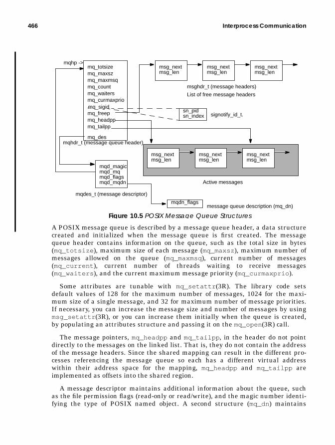
466 Interprocess Communication
A POSIX message queue is described by a message queue header, a data structurecreated and initialized when the message queue is first created. The messagequeue header contains information on the queue, such as the total size in bytes(mq_totsize ), maximum size of each message (mq_maxsz), maximum number ofmessages allowed on the queue (mq_maxmsq), current number of messages(mq_current ), current number of threads waiting to receive messages(mq_waiters ), and the current maximum message priority (mq_curmaxprio ).
Some attributes are tunable with mq_setattr (3R). The library code setsdefault values of 128 for the maximum number of messages, 1024 for the maxi-mum size of a single message, and 32 for maximum number of message priorities.If necessary, you can increase the message size and number of messages by usingmsg_setattr (3R), or you can increase them initially when the queue is created,by populating an attributes structure and passing it on the mq_open(3R) call.
The message pointers, mq_headpp and mq_tailpp , in the header do not pointdirectly to the messages on the linked list. That is, they do not contain the addressof the message headers. Since the shared mapping can result in the different pro-cesses referencing the message queue so each has a different virtual addresswithin their address space for the mapping, mq_headpp and mq_tailpp areimplemented as offsets into the shared region.
A message descriptor maintains additional information about the queue, suchas the file permission flags (read-only or read/write), and the magic number identi-fying the type of POSIX named object. A second structure (mq_dn) maintains
mq_totsizemq_maxszmq_maxmsqmq_countmq_waitersmq_curmaxprio
mq_freepmq_headppmq_tailpp
mqhdr_t (message queue header)
mqhp ->
mq_des
msg_nextmsg_len
mqd_magicmqd_mqmqd_flagsmqd_mqdn
msghdr_t (message headers)
mqdes_t (message descriptor)
msg_nextmsg_len
msg_nextmsg_len
List of free message headers
Active messages
msg_nextmsg_len
msg_nextmsg_len
msg_nextmsg_len
msg_nextmsg_len
msg_nextmsg_len
msg_nextmsg_len
mqdn_flagsmessage queue description (mq_dn)
_sn_pidsn_index
mq_sigid
signotify_id_t.
Figure 10.5 POSIX Message Queue Structures

POSIX IPC 467
per-process flags on the message, allowing different processes to specify eitherblocking or nonblocking behavior on the message queue files. This is analogous toregular file flags, where a file descriptor for an open file is maintained at the pro-cess level, and different processes can have different flags set on the same file. (Forexample, one process could have the file opened for read/write and another processcould have the same file opened read-only.)
With the big picture in place (Figure 10.5), let’s take a look at what happenswhen a message queue is created and opened.
• When mq_open() is entered, it creates the lock file and acquires a file lock.All the message queue files use the /tmp directory and follow a file name con-vention similar to that described in the semaphore section. That is, file namesbegin with a prefix—.MQD (data file), .MQL (lock file), .MQP (permission file),or .MQN(description file)—and end with the appended file name passed as anargument to mq_open(3R) minus the slash character.
• If a new message queue is being created, the maximum message size andmessages per queue sizes are set, either with the default values or from apassed attributes structure in the mq_open(3R) call.
• The permission file is opened, permissions are verified, and the file isclosed.
• The total amount of space needed for messages, based on the limitsand structure size, is calculated, and the data file is created, opened,and set to the appropriate size with ftruncate (3C).
• If a new message queue is not being created, then an existing queue is beingopened, in which case the permission test is done and the queue data file istested to ensure the queue has been initialized.
The steps described next apply to a new or existing message queue; the latter caseis a queue being opened by another process.
• Space for a message queue descriptor is malloc ’d (mqdes_t ), and the datafile is mmap’d into a shared address space, setting the mqhp pointer (Figure10.5) as the return address from the mmap(2) call.
• The message queue descriptor file is created, opened, mmap’d (also into ashared address space), and closed.
• For new message queues, the mq_init() function (not part of the API) iscalled to complete the initialization process. Each message queue header hasseveral semaphores (not shown in Figure 10.5) used to synchronize access tothe messages, the header structure, and other areas of the queue infrastruc-ture.mq_init() initializes the semaphores with calls to sem_init() , which ispart of the libposix4.so library.

468 Interprocess Communication
• The queue head (mq_headpp ), tail (mq_tailpp ), and free (mq_freep ) point-ers are set on the message header structure, and mq_init() returns tomq_open() , completing the open process.
Once a queue is established, processes insert and remove messages by usingmq_send(3R) and mq_receive (3R).
• mq_send(3R) does some up-front tests on the file type (mqd_magic ) and teststhe mq_notfull semaphore for space on the queue.
• If the process’s queue flag is set for nonblocking mode,sem_trywait() is called and returns to the process if the semaphoreis not available, meaning there’s no space on the queue.
• Otherwise, sem_wait() is called, causing the process to block untilspace is available.
• Once space is available, sem_wait() is called to acquire the mq_exclusivemutex, which protects the queue during message insertions and removals.
POSIX message queues offer an interesting feature that is not available with Sys-tem V message queues: automatic notification to a process or thread when a mes-sage has been added to a queue. An mq_notify (3R) interface can be issued by aprocess that needs to be notified of the arrival of a signal. To continue with thesequence for the next code segment:
• mq_send() checks to determine if a notification has been set up by testingthe mq_sigid structure’s sn_pid field. If it is non-NULL, the process hasrequested notification, and a notification signal is sent if no other processesare already blocked, waiting for a message.
• Finally, the library’s internal mq_putmsg() function is called to locate thenext free message block of the free list (mq_freep ) and to place the messageon the queue.
For receiving messages:
• mq_receive() issues a sem_trywait() call on the mq_notempty sema-phore.
• If the queue is empty and the descriptor has been set to nonblock,sem_trywait() returns with an EAGAIN error to the caller.
• Otherwise, the mq_rblocked semaphore is incremented (sem_post ),and sem_wait() is called.
• Once a message shows up on the queue, the mq_exclusive semaphore isacquired, and the internal mq_getmsg() function is called.
• The next message is pulled off the head of the queue, and the pointers areappropriately adjusted.

Solaris Doors 469
Our description omits some subtle details, mostly around the priority mechanismavailable for POSIX message queues. A message priority can be specified in themq_send(3R) and mq_receive (3R) calls. Messages with better priorities (largernumeric values) are inserted into the queue before messages of lower priority, sohigher-priority messages are kept at the front of the queue and will be removedfirst. The use and behavior of message priorities is well documented in the man-ual pages, as well as in Steven’s UNIX Network Programming—Interprocess Com-munication [25].
10.6 Solaris Doors
Doors provide a facility for processes to issue procedure calls to functions in otherprocesses running on the same system. Using the APIs, a process can become adoor server, exporting a function through a door it creates by using thedoor_create (3X) interface. Other processes can then invoke the procedure byissuing a door_call (3X), specifying the correct door descriptor. Our goal here isnot to provide a programmer’s guide to doors but rather to focus on the kernelimplementation, data structures, and algorithms. Some discussion of the APIs is,of course, necessary to keep things in context, but we suggest that you refer to themanual pages and to Steven’s book [25] to understand how to develop applicationswith doors.
The door APIs were available in Solaris 2.5.1 but not documented and, at thatpoint, subject to change. Solaris 2.6 was the first Solaris release that included arelatively stable set of interfaces (stable in the sense that they were less likely tochange). The Solaris kernel ships with a shared object library, libdoor.so , thatmust be linked to applications using the doors APIs. Table 10-10 describes the doorAPIs available in Solaris 2.6 and Solaris 7. During the course of our coverage ofdoors, we refer to the interfaces as necessary for clarity.
Table 10-10 Solaris Doors Interfaces
Interface Descriptiondoor_create (3X) Creates a door. Called from a door server to
associate a procedure within the program witha door descriptor. The door descriptor, returnedby door_create (3X), is used by client pro-grams that wish to invoke the procedure.
door_revoke (3X) Revokes client access to the door. Can only becalled by the server.
door_call (3X) Invokes a function exported as a door. Calledfrom a client process.

470 Interprocess Communication
10.6.1 Doors OverviewFigure 10.6 illustrates broadly how doors provide an interprocess communica-
tion mechanism.
Figure 10.6 Solaris Doors
The file abstraction used by doors is the means by which client kernel threadsretrieve the proper door handle required to issue a door_call (3X). It is similar tothe methodology employed when POSIX IPC facilities are used; a path name in thefile system name space is opened, and the returned file descriptor is passed as anargument in the door_call (3X) to call into the desired door. An argument struc-ture, door_arg_t , is declared by the client code and used for passing argumentsto the door server function being called. The address of the door_arg_t structureis passed as the second argument by the client in door_call (3X).
On the server side, a function defined in the process can be made available toexternal client processes by creation of a door (door_create (3X)). The servermust also bind the door to a file in the file system name space. This is done withfattach (3C), which binds a STREAMS-based or door file descriptor to a file sys-tem path name. Once the binding has been established, a client can issue an opento the path name and use the returned file descriptor in door_call (3X).
door_return (3X) Returns from a door function. Typically usedas the last function call in a routine exportedas a door.
door_info (3X) Fetches information about a door.door_server_create (3X) Specifies a door thread create function.door_cred (3X) Fetches client credential information.door_bind (3X)
door_unbind (3X)
Associates the calling thread with a doorthread pool.Removes current thread from door pool.
Table 10-10 Solaris Doors Interfaces
Interface Description
door_call()
function()door_return();
door_create(function,...,...)main()main()
client process
door server process

Solaris Doors 471
10.6.2 Doors Implementation
Doors are implemented in the kernel as a pseudofile system, doorfs , which isloaded from the /kernel/sys directory during boot. Within a process, a door isreferenced through its door descriptor, which is similar in form and function to afile descriptor, and, in fact, the allocation of a door descriptor in a process uses anavailable file descriptor slot.
The major data structures required for doors support are illustrated in Figure10.7
Figure 10.7 Solaris Doors Structures
The two main structures are door_node , linked to the process structure with thep_door_list pointer, and door_data , linked to the door_node with thedoor_data pointer. A process can be a door server for multiple functions (multi-ple doors). Each call to door_create (3X) creates another door_node , which linksto an existing door_node (if one already exists) through the door_list .door_data is created as part of the setup of a server thread during the create pro-cess, which we’re about to walk through. door_data includes a door_arg struc-ture, which manages the argument list passed in door_call (3X), and a link to a
door_vnode
door_targetdoor_listdoor_ulist(*door_pc)()door_datadoor_indexdoor_flagsdoor_activedoor_servers
door_node
process structure
embeddedvnodestructure
p_door_list
p_server_threadsp_unref_listp_server_cvp_unref_thread
additionaldoor nodesin this process
kthread
d_args
d_callerd_serversd_actived_poold_spd_bufd_bufsized_errord_fpp_sized_fppd_upcalld_noresultsd_overflowd_flagd_kerneld_cv
door_data
kthread
thread thatissueddoor_call()
t_door
data_ptrdata_sizedesc_ptrdesc_numrbufrsizedoor_arg
d_attributesd_datadoor_desc

472 Interprocess Communication
door descriptor (door_desc ), used for passing door descriptors when a door func-tion is called.
To continue: A call to door_create (3X) enters the libdoor.so librarydoor_create() entry point (as is the case with any library call).
• The kernel door_create() is invoked from the library and performs the fol-lowing actions:
• Allocates kernel memory for door_node and initializes several fieldsof door_node and the door vnode (part of the door_node structure).
• Links the door_target field to the process structure of the callingkernel thread
• Sets door_pc , a function pointer, to the address of the function beingserved by the door (the code that will execute when a client callsdoor_call (3X))
• Sets door_flags as directed by the attributes passed by the caller.
• Initializes the vnode mutex lock (v_lock) and condition variable(v_cv ). Initializes several other fields in the vnode to specify thevnode type (VDOOR) and references to the vnode operations and vir-tual file system (VFS) switch table entries of the doorfs file system.
• Adds the door_node to the process’s door list (p_door_list ) and allo-cates a file descriptor for the door descriptor by means of the kernelfalloc() function, which allocates a file structure and user filedescriptor.
• The kernel door_create() now completed, the code returns to the lib-door.so door_create() code.
• The library code makes sure that the calling process has been linked with theSolaris threads library, libthread.so and returns an error if the link hasnot been made.A door server requires linking with libthread.so because the door codeuses the threads library interfaces to create and manage a pool of door serverthreads.
• The last thing the library-level door_create() code does is callthr_create (3T) to create a server thread for the door server, as an execu-tion resource for calls into the function being exported by the door server.
• thr_create (3T) creates a detached, bound thread that executes the librarydoor_create_func() routine, which disables cancellation of the currentthread (pthread_setcancelstate (3T)) and enters the kerneldoor_return() code.

Solaris Doors 473
door_return (3X) is part of the doors API and is typically called at the end of thefunction being exported by the door_create (3X) call.
• door_return (3X) returns processor control to the thread that issueddoor_call (3X) and causes the server thread to sleep, waiting for anotherinvocation of the door function.
• When entered (remember, we’re in the kernel now, not in the doors library),door_return() allocates a door_data structure for the calling thread andlinks it to the kernel thread’s t_door pointer.This sequence is done if the current thread’s t_door pointer is NULL, signify-ing a door_data structure has not yet been allocated.
The next bit of code in door_return() applies to argument handling, returndata, and other conditions that need to be dealt with when a kernel thread issuesdoor_call (3X). We’re still in the door create phase, so a bit later we’ll revisitwhat happens in door_return() as a result of door_call (3X).
Continuing with the door create in the door_return() kernel function:
• The kernel door_release_server() code is called to place the currentthread on the list of threads available to execute on behalf of door calls intothe server.
• The kernel thread is linked to the process’s p_server_thread link, andcv_broadcast() is done on the door condition variable, door_cv , causingany threads blocked in door_call (3X) to wake up.At this point, the door create is essentially completed.
• A call into the shuttle code to place the kernel thread to sleep on a shuttlesynchronization object is made (shuttle_swtch() ); the thread is thusplaced in a sleep state and enters the dispatcher through swtch() .
We now digress slightly to explain shuttle synchronization objects. Typically, exe-cution control flow is managed by the kernel dispatcher (Chapter 5), using condi-tion variables and sleep queues. Other synchronization primitives, mutex locks,and reader/writer locks are managed by turnstiles, an implementation of sleepqueues that provides a priority inheritance mechanism.
Shuttle objects are a relatively new (introduced in Solaris 2.5, when doors firstshipped) synchronization object that essentially allows very fast transfer of con-trol of a processor from one kernel thread to another without incurring the over-head of the dispatcher queue searching and normal kernel thread processing. Inthe case of a door_call() , control can be transferred directly from the caller (orclient in this case), to a thread in the door server pool, which executes the doorfunction on behalf of the caller. When the door function has completed, control istransferred directly back to the client (caller), all using the kernel shuttle inter-faces to set thread state and to enter the dispatcher at the appropriate places. Thisdirect transfer of processor control contributes significantly to the IPC perfor-

474 Interprocess Communication
mance attainable with doors. Shuttle objects are currently used only by the doorssubsystem in Solaris.
Kernel threads sleeping on shuttle objects have a 0 value in their wait channelfield (t_wchan ) and a value of 1 in t_wchan0 . The thread’s t_sobj_ops (synchro-nization object operations table) pointer is set to the shuttle object’s operationsstructure (shuttle_sops ); the thread’s state is, of course, TS_SLEEP, and thethread’s T_WAKEABLE flag is set.
Getting back to door creation:
• A default of one server thread is created unless there are concurrent invoca-tions, in which case a thread will be created for each door call. The API allowsfor programs creating their own separate, private pool of door threads thathave different characteristics than the default thread properties.
• The doors library will create a bound, detached thread with the defaultthread stack size and signal disposition by default.This completes the creation of a door server. A server thread in the door poolis left sleeping on a shuttle object (the call to shuttle_swtch() ), ready toexecute the door function.
Application code that creates a door to a function (becomes a door server) typicallycreates a file in the file system to which the door descriptor can be attached, usingthe standard open (2) and fattach (3C) APIs, to make the door more easily acces-sible to other processes.
The fattach (3C) API has traditionally been used for STREAMS code, where itis desirable to associate a STREAM or STREAMS-based pipe with a file in the filesystem name space, for precisely the same reason one would wish to associate adoor descriptor with a file name; that is, to make the descriptor easily accessible toother processes on the system so application software can take advantage of theIPC mechanism. The door code can leverage from the fact that the binding of anobject to a file name, when that object does not meet the traditional definition ofwhat a file is, has already been solved.
fattach (3C) is implemented with a pseudo file system called namefs , the namefile system. namefs allows the mounting of file systems on nondirectory mountpoints, as opposed to the traditional mounting of a file system that requires theselected mount point to be a directory file. Currently, fattach (3C) is the only cli-ent application of namefs ; it calls the mount (2) system call, passing namefs as thefile system name character string and a pointer to a namefs file descriptor. Themount (2) system call enters the VFS switch table through the VFS_MOUNTmacroand enters the namefs mount code, nm_mount() .
With the door server in place, client processes are free to issue a door_call (3X)to invoke the exported server function.

Solaris Doors 475
• The kernel door_call() code (nothing happens at the doors library level indoor_call() ) allocates a door_data structure from kernel memory andlinks it to the t_door pointer in the calling kernel thread.
• If a pointer to an argument structure (door_arg ) was passed in thedoor_call (3X), the arguments are copied from the passed structurein user space to the door_arg structure embedded in door_data.
• If no arguments were passed, the door_arg fields are zeroed and thed_noresults flag in door_data is set to indicate no results can bereturned.
The door_call (3X) API defines that a NULL argument pointer means noresults can be returned. A lookup is performed on the passed door descriptorand returns a pointer to the door_node . Typically, file descriptor lookupsreturn a vnode pointer. In this case, the vnode pointer and the door_nodepointer are one and the same because the vnode is embedded in thedoor_node , located at the top of the structure.
• The kernel door_get_server() function retrieves a server kernel threadfrom the pool to execute the function.
• The thread is removed from the list of available server threads(p_server_threads ) and changed from TS_SLEEP to TS_ONPROCstate (this kernel thread was sleeping on a shuttle object, not sitting ona sleep queue).
• The arguments from the caller are copied to the server thread returnedfrom door_get_server() . The door_active counter in thedoor_node is incremented, the calling (client) thread’s d_error field(in door_data ) is set to DOOR_WAIT, the door server thread’sd_caller field (door_data structure for the server thread) is set tothe client (caller), and a pointer to the door_node is set in the serverthread’s door_data d_active field.
With the necessary data fields set up, control can now be transferred to theserver thread; this transfer is done with a call to shuttle_resume() .
• shuttle_resume() is passed a pointer to the server thread removed fromthe door pool.
Just to get back to the forest for a moment (in case you’re lost among the trees),we’re into shuttle_resume() as a result of a kernel thread issuingdoor_call (3X). The door_call() kernel code up to this point essentially allo-cated or initialized the necessary data structures for the server thread to have theexported function executed on behalf of the caller. The shuttle_resume() func-tion is entered from door_call() , so the kernel thread now executing inshuttle_resume() is the door client. So, what needs to happen is really prettysimple (relatively speaking)—the server thread, which was passed toshuttle_resume() as an argument, needs to get control of the processor, and the

476 Interprocess Communication
current thread executing the shuttle_resume() code needs to be put to sleep ona shuttle object, since the current thread and the door client thread are one andthe same. So:
• shuttle_resume() sets up the current thread to sleep on a shuttle object inthe same manner described previously (t_wchan0 set to 1, state set toTS_SLEEP, etc.); the server thread has its T_WAKEABLEflag, t_wchan0 field,and t_sobj_ops field cleared.
• The code tests for any interesting events that may require attention, such asa hold condition on the thread, and checks for posted signals. If any signalsare posted, setrun() is called with the current (client) thread.
• Finally, the dispatcher swtch_to() function is called and is passed theserver thread address. swtch_to() updates the per-processor con-text-switch counter in the cpu_sysinfo structure (pswitch ) and callsresume() to have the server thread context-switched onto the processor. Thegeneral flow is illustrated in Figure 10.8.
Figure 10.8 door_call() Flow with Shuttle Switching
• The server thread executes the function associated with the door_node , asspecified by the first argument passed when the server executeddoor_create (3X).
• The last call made by the server function is door_return (3X), which returnsresults and control to the calling thread (client) and blocks in the server, wait-ing for another door_call (3X).
door_call() = door_get_server()
currentthread
serverthread
shuttle_resume(server_thread)
current thread set toTS_SLEEP onshuttle object
swtch_to(server_thread)
resume(server_thread)
client threadsleeping
CPU
CPU
serverthreadnow runningon CPU

Solaris Doors 477
• The kernel door_return() code copies the return data back to the callerand places the server thread back in the door server pool. The calling (client)thread, which we left in a sleep state back in door_call() , is set back to anT_ONPROCstate, and the shuttle code (shuttle_resume() ) is called to givethe processor back to the caller and have it resume execution.
Some final points to make regarding doors. There’s a fair amount of code in thekernel doorfs module designed to deal with error conditions and the prematuretermination of the calling thread or server thread. In general, if the calling threadis awakened early, that is, before door_call() has completed, the code figuresout why the wakeup occurred (signal, exit call, etc.) and sends a cancel signal(SIGCANCEL) to the server thread. If a server thread is interrupted because of asignal, exit, error condition, etc., the door_call() code bails out. In the client, anEINTR (interrupted system call) error will be set, signifying that door_call()terminated prematurely.

478 Interprocess Communication

Part Four
FILES AND FILESYSTEMS
• Files and File I/O• File System Overview• File System Framework• The UFS File System• File System Caching
479

480
read()
write() fread()fwrite()
mmap()aioread()
aiowrite()
/dev/rdsk/.../dev/rdsk/...
DataDisks
Swap Disk
Regular File Systems
Directory Structures File System Blocks
Directory NameLookup Cache
Old Buffer Cache(BUFHWM)
Stdio Libraries Async IO Library
Special
Volume Manager Layer - Disk Suite, VxVM
File Segment
Paged VNODE VM Core
(File System Cache & Page Cache)
NFS
Ser
ver
Meta Data (Inode)Cache
VNODE Segment
ApplicationMemory(HEAP)
Block I/O Interface
directI/O
driver (seg_map) driver (seg_vn)
read / write aio Binary (Text)Binary (Data)
Stack
Heap
File Sys.(specfs)
( ufs, vxfs, pcfs etc )
SCSI/Device Driver Framework
seg_drv
The Solaris File I/O System

11
SOLARIS FILES ANDFILE I/O
From its inception, Unix has been built around two fundamental entities: pro-cesses and files. Everything that is executed on the system is a process, and all pro-cess I/O is done to a file. We saw in previous chapters how the process model hasevolved and how the kernel thread is the unit of execution in the Solaris kernel.The implementation of files and file I/O facilities has also seen some changes sincethe early versions of UNIX. The notion of a file now includes more abstract types,and the interfaces available for doing file I/O have expanded.
In this chapter, we look at the implementation of files in Solaris and discusssome of the abstract file types and the file I/O facilities.
11.1 Files in Solaris
Generically defined, a file is an entity that stores data as an array of bytes, begin-ning at byte zero and extending to the end of the file. The contents of the file (thedata) can take any number of forms: a simple text file, a binary executable file, adirectory file, etc. Solaris supports many types of files, several of which are definedat the kernel level, meaning that some component of the kernel has intimateknowledge of the file’s format by virtue of the file type. An example is a directoryfile on a UFS file system—directory files have a specific format that is known tothe UFS kernel routines designed for directory I/O.
The number of file types in the kernel has increased over the last several yearswith the addition new kernel abstractions in the form of pseudofiles. Pseudofiles
481

482 Solaris Files and File I/O
provide a means by which the kernel can abstract as a file a binary object, like adata structure in memory. Users and programmers view the object as a file, in thatthe traditional file I/O operations are supported on it (for the most part). It’s apseudofile because it is not an on-disk file; it’s not a real file in the traditionalsense.
Under the covers, the operations performed on the object are managed by thefile system on which the file resides. A specific file type often belongs to an under-lying file system that manages the storage and retrieval of the file and defines thekernel functions for I/O and control operations on the file. ( See Chapter 14, “TheUnix File System”," for details about file systems.) Table 11-1 lists the varioustypes of files implemented in Solaris.
Table 11-1 Solaris File Types
File Type FileSystem
CharacterDesignation
Description
Regular UFS — A traditional on-disk file. Can be atext file, binary shared object, orexecutable file.
Directory UFS d A file that stores the names of otherfiles and directories. Other file sys-tems can implement directorieswithin their own file hierarchy.
SymbolicLink
UFS l A file that represents a link toanother file, potentially in anotherdirectory or on another file system.
CharacterSpecial
specfs c A device special file for devicescapable of character mode I/O.Device files represent I/O deviceson the system and provide a meansof indexing into the device driverand uniquely identifying a specificdevice.
Block Spe-cial
specfs b As above, a device special file fordevices capable of block-mode I/O,such as disk and tape devices
Named Pipe(FIFO)
fifofs p A file that provides a bidirectionalcommunication path between pro-cesses running on the same system.
Door doorfs D Part of the door interprocess com-munication facility. Doors provide ameans of doing very fast interpro-cess procedure calling and messageand data passing.
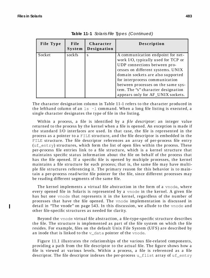
Files in Solaris 483
The character designation column in Table 11-1 refers to the character produced inthe lefthand column of an ls -l command. When a long file listing is executed, asingle character designates the type of file in the listing.
Within a process, a file is identified by a file descriptor: an integer valuereturned to the process by the kernel when a file is opened. An exception is made ifthe standard I/O interfaces are used. In that case, the file is represented in theprocess as a pointer to a FILE structure, and the file descriptor is embedded in theFILE structure. The file descriptor references an array of per-process file entry(uf_entry ) structures, which form the list of open files within the process. Theseper-process file entries link to a file structure, which is a kernel structure thatmaintains specific status information about the file on behalf of the process thathas the file opened. If a specific file is opened by multiple processes, the kernelmaintains a file structure for each process; that is, the same file may have multi-ple file structures referencing it. The primary reason for this behavior is to main-tain a per-process read/write file pointer for the file, since different processes maybe reading different segments of the same file.
The kernel implements a virtual file abstraction in the form of a vnode , whereevery opened file in Solaris is represented by a vnode in the kernel. A given filehas but one vnode that represents it in the kernel, regardless of the number ofprocesses that have the file opened. The vnode implementation is discussed indetail in “The vnode” on page 543. In this discussion, we allude to the vnode andother file-specific structures as needed for clarity.
Beyond the vnode virtual file abstraction, a file-type-specific structure describesthe file. The structure is implemented as part of the file system on which the fileresides. For example, files on the default Unix File System (UFS) are described byan inode that is linked to the v_data pointer of the vnode .
Figure 11.1 illustrates the relationships of the various file-related components,providing a path from the file descriptor to the actual file. The figure shows how afile is viewed at various levels. Within a process, a file is referenced as a filedescriptor. The file descriptor indexes the per-process u_flist array of uf_entry
Socket sockfs s A communication endpoint for net-work I/O, typically used for TCP orUDP connections between pro-cesses on different systems. UNIXdomain sockets are also supportedfor interprocess communicationbetween processes on the same sys-tem. The “s” character designationappears only for AF_UNIX sockets.
Table 11-1 Solaris File Types (Continued)
File Type FileSystem
CharacterDesignation
Description

484 Solaris Files and File I/O
structures, which link to the kernel file structure. The file is abstracted in the ker-nel as a virtual file through the vnode , which links to the file-specific structures(based on the file type) through the v_data pointer in the vnode .
Figure 11.1 File-Related Structures
The process-level uf_entry structures are allocated dynamically in groups of 24as files are opened, up to the per-process open file limit. The uf_entry structurecontains a pointer to the file structure (uf_ofile ) and a uf_pofile flag fieldused by the kernel to maintain file state information. The possible flags are FRE-SERVED, to indicate that the slot has been allocated, FCLOSING, to indicate that afile-close is in progress, and FCLOSEXEC, a user-settable close-on-exec flag, whichinstructs the kernel to close the file descriptor if an exec (2) call is executed.uf_entry also maintains a reference count in the uf_refcnt member. This countprovides a means of tracking multiple references to the file in multithreaded pro-cesses.
The kernel establishes a default hard and soft limit for the number of files aprocess can have opened at any time. rlim_fd_max is the hard limit, andrlim_fd_cur is the current limit (or soft limit). A process can have up torlim_fd_cur file descriptors and can increase the number up to rlim_fd_max .You can set these parameters systemwide by placing entries in the /etc/systemfile:
set rlim_fd_max=8192set rlim_fd_cur=1024
f_vnodef_offsetf_credf_count
kernel filestructures
v_flagsv_typev_countv_data
kernelvnodes
inode
disk blocks
filedescriptor
uf_ofileuf_pofileuf_refcntuf_ofileuf_pofileuf_refcntuf_ofileuf_pofileuf_refcnt
u_flist
process
Virtual file abstractionFile-type-specificstructures and linksProcess view of an opened file
rnode
networkfile
pnodekernelobject
...
uf_entry {

Files in Solaris 485
You can alter the per-process limits either directly from the command line with thelimit (1) or ulimit (1) shell commands or programmatically with setrlimit (2).The actual number of open files that a process can maintain is driven largely bythe file APIs used. For 32-bit systems, if the stdio (3S) interfaces are used, thelimit is 256 open files. This limit results from the data type used in the FILE struc-ture for the actual file descriptor. An unsigned 8-bit data type, which has a rangeof values of 0–255, is used. Thus, the maximum number of file descriptors is lim-ited to 256 for 32-bit stdio (3S)-based programs. For 64-bit systems (and 64-bitprocesses), the stdio (3S) limit is 64 Kbytes.
The select (3C) interface, which provides a mechanism for file polling, imposesanother API limit. select (3C) limits the number of open files to 1 Kbyte on 32-bitsystems, with the exception of 32-bit Solaris 7. In 32-bit Solaris 7, select (3C) canpoll up to 64-Kbyte file descriptors. If you use file descriptors greater than 1-Kbytewith select (3C) on 32-bit Solaris 7, then you must declare FD_SETSIZE in theprogram code. On 64-bit Solaris 7, a 64-bit process has a default file descriptor setsize (FD_SETSIZE) of 64 Kbytes. Table 11-2 summarizes file descriptor limitations.
Those limitations aside, there remain only the practical limits that govern thenumber of files that can be opened on a per-process and systemwide basis. A prac-tical limit from a per-process perspective really comes down to two things: how theapplication software is designed; and what constitutes a manageable number offile descriptors within a single process, such that the maintenance, performance,portability, and availability requirements of the software can be met. The filedescriptors and uf_entry structures do not require a significant amount of mem-ory space, even in large numbers, so per-process address space limitations are typi-cally not an issue when it comes to the number of open files.
Table 11-2 File Descriptor Limits
Interface (API) Limit Notesstdio (3S) 256 All 32-bit systems.stdio (3S) 64K
(65536)64-bit programs only (Solaris 7 andlater).
select (3C) 1K(1024)
All 32-bit systems. Default value for32-bit Solaris 7.
select (3C) 64K(65536)
Attainable value on 32-bit Solaris 7.Requires you to add:#define FD_SETSIZE 65536to program code before inclusion on addi-tional system header files.
select (3C) 64K(65536)
Default for 64-bit Solaris 7 (and beyond).

486 Solaris Files and File I/O
11.1.1 Kernel File Structures
The Solaris kernel does not implement a system file table in the traditional sense.That is, the systemwide list of file structures is not maintained in an array or as alinked list. A kernel object cache segment is allocated to hold file structures, andthey are simply allocated and linked to the process and vnode as files are createdand opened.
We can see in Figure 11.1 that each process uses file descriptors to reference afile. The file descriptors ultimately link to the kernel file structure, defined as afile_t data type, shown below.
The fields maintained in the file structure are, for the most part, self-explanatory.The f_tlock kernel mutex lock protects the various structure members. Theseinclude the f_count reference count, which lists how many threads have the fileopened, and the f_flag file flags, described in “File Open Modes and File Descrip-tor Flags” on page 495.
Solaris allocates file structures for opened files as needed, growing the open filecount dynamically to meet the requirements of the system load. Therefore, themaximum number of files that can be opened systemwide at any time is limited byavailable kernel address space, and nothing more. The actual size to which thekernel can grow depends on the hardware architecture of the system and theSolaris version the system is running. The key point is that a fixed kernel limit ona maximum number of file structures does not exist.
The system initializes space for file structures during startup by callingfile_cache() , a routine in the kernel memory allocator code that creates a ker-nel object cache. The initial allocation simply sets up the file_cache pointer withspace for one file structure. However, the kernel will have allocated several filestructures by the time the system has completed the boot process and is availablefor users, as all of the system processes that get started have some opened files. Asfiles are opened/created, the system either reuses a freed cache object for the file
typedef struct file { kmutex_t f_tlock; /* short-term lock */ ushort_t f_flag; ushort_t f_pad; /* Explicit pad to 4-byte boundary */ struct vnode *f_vnode; /* pointer to vnode structure */ offset_t f_offset; /* read/write character pointer */ struct cred *f_cred; /* credentials of user who opened it */ caddr_t f_audit_data; /* file audit data */ int f_count; /* reference count */} file_t;
Header File <sys/file.h>

Files in Solaris 487
entry or creates a new one if needed. You can use /etc/crash as root to examinethe file structures.
The ADDRESS column is the kernel virtual memory address of the file structure.RCNT is the reference count field (f_count ). TYPE is the type of file, and ADDR isthe kernel virtual address of the vnode . OFFSET is the current file pointer, andFLAGS are the flags bits currently set for the file.
You can use sar (1M) for a quick look at how many files are opened systemwide.
This example shows 603 opened files. The format of the sar output is a holdoverfrom the early days of static tables, which is why it is displayed as 603/603. Origi-nally, the value on the left represented the current number of occupied table slots,and the value on the right represented the maximum number of slots. Since filestructure allocation is completely dynamic in nature, both values will always bethe same.
# crashdumpfile = /dev/mem, namelist = /dev/ksyms, outfile = stdout> fileADDRESS RCNT TYPE/ADDR OFFSET FLAGS3000009e008 1 FIFO/300009027e0 0 read write3000009e040 1 UFS /3000117dc68 535 write appen3000009e078 1 SPEC/300008ed698 3216 write appen3000009e0b0 1 UFS /300010d8c98 0 write3000009e0e8 1 UFS /30001047ca0 4 read write3000009e120 2 DOOR/30000929348 0 read write3000009e158 1 SPEC/30000fb45d0 0 read3000009e1c8 1 UFS /300014c6c98 106 read write3000009e200 1 SPEC/30000c376a0 0 write3000009e238 2 DOOR/30000929298 0 read write3000009e270 3 SPEC/300008ecf18 0 read3000009e2a8 1 UFS /30000f5e0f0 0 read3000009e2e0 1 SPEC/30000fb46c0 0 read write3000009e318 1 UFS /300001f9dd0 0 read3000009e350 1 FIFO/30000902c80 0 read write
# sar -v 3 3
SunOS devhome 5.7 Generic sun4u 08/01/99
11:38:09 proc-sz ov inod-sz ov file-sz ov lock-sz11:38:12 100/5930 0 37181/37181 0 603/603 0 0/011:38:15 100/5930 0 37181/37181 0 603/603 0 0/011:38:18 101/5930 0 37181/37181 0 607/607 0 0/0

488 Solaris Files and File I/O
For a specific process, you can use the pfiles (1) command to create a list of allthe files opened.
In the preceding example, the pfiles command is executed on PID 585. The PIDand process name are dumped, followed by a listing of the process’s opened files.For each file, we see a listing of the file descriptor (the number to the left of thecolon), the file type, file mode bits, the device from which the file originated, theinode number, file UID and GID, and the file size.
11.2 File Application Programming Interfaces (APIs)
Several different APIs perform file I/O in Solaris. These include standard I/O—thegeneric C buffered I/O mechanism—and several flavors of low-level operating sys-tem file I/O.
The traditional C buffered interfaces are known as the Standard I/O functions,abbreviated as stdio . They are the buffered I/O interfaces that were added toUnix V6 by Bell Laboratories in 1976; they appear as a standard file I/O mecha-nism in nearly all C runtime environments. These stdio library interfaces existas a layer above the lower-level system calls.
Of the several different types of system I/O, the most basic are the read andwrite system calls. The more advanced (and more recent) are POSIX I/O through
$ pfiles 585585: /space1/framemaker,v5.5.3/bin/sunxm.s5.sparc/maker -xrm *iconX:0 -xrm Current rlimit: 64 file descriptors 0: S_IFCHR mode:0666 dev:32,24 ino:143523 uid:0 gid:3 rdev:13,2 O_RDONLY|O_LARGEFILE 1: S_IFCHR mode:0666 dev:32,24 ino:143523 uid:0 gid:3 rdev:13,2 O_WRONLY|O_APPEND|O_LARGEFILE 2: S_IFCHR mode:0666 dev:32,24 ino:143523 uid:0 gid:3 rdev:13,2 O_WRONLY|O_APPEND|O_LARGEFILE 3: S_IFIFO mode:0666 dev:176,0 ino:4132162568 uid:0 gid:0 size:0 O_RDWR|O_NONBLOCK FD_CLOEXEC 4: S_IFDOOR mode:0444 dev:176,0 ino:4127633624 uid:0 gid:0 size:0 O_RDONLY|O_LARGEFILE FD_CLOEXEC door to nscd[202] 5: S_IFREG mode:0644 dev:32,9 ino:3643 uid:19821 gid:10 size:297984 O_RDONLY FD_CLOEXEC 6: S_IFREG mode:0644 dev:32,8 ino:566 uid:19821 gid:10 size:29696 O_RDWR FD_CLOEXEC 7: S_IFREG mode:0644 dev:32,8 ino:612 uid:19821 gid:10 size:0 O_RDWR FD_CLOEXEC 8: S_IFREG mode:0644 dev:32,8 ino:666 uid:19821 gid:10 size:0 O_RDWR FD_CLOEXEC 9: S_IFCHR mode:0000 dev:32,24 ino:360 uid:0 gid:0 rdev:41,104 O_RDWR FD_CLOEXEC 10: S_IFREG mode:0644 dev:32,9 ino:38607 uid:19821 gid:10 size:65083 O_RDONLY 11: S_IFREG mode:0644 dev:32,8 ino:667 uid:19821 gid:10 size:4096 O_RDWR

File Application Programming Interfaces (APIs) 489
pread and pwrite system calls and scatter/gather I/O through the readv andwritev system calls. Asynchronous I/O is done through either the aio_read (3R)and aio_write (3R) interfaces, which are part of the posix4 library, or aio-read (3) and aiowrite (3), which are part of the libaio library. Both sets of asyn-chronous I/O interfaces provide similar functionality; they differ in how they areused in application code.
Figure 11.2 shows the general relationships among the various file-related APIsand the underlying kernel subsystems.
Figure 11.2 Kernel File I/O Interface Relationships
11.2.1 Standard I/O (stdio)
The standard I/O functions allow a file to be opened as a “stream” of bytes, knownas a file stream. This approach allows a C program to access the file by readingand writing characters and arbitrary length strings, while the underlying librar-ies deal with the system calls necessary to implement the real I/O operations. Thisdesign has the advantage that it is completely portable, even across different oper-ating systems, and the programmer does not need to consider any underlying
File Systems / File System Cache
Standard I/O Buffer
read() / write()fread() fwrite()
User Process
pread() /pwrite()
Raw Devices (/dev/rdsk...)
aioread()aiowrite()
Async I/O
(via Threads)
KernelAsync I/O
(via Drivers)
readv()/writev()
(libc.so)
(libaio or libposix4)
aio_read()aio_write()
KAIO

490 Solaris Files and File I/O
machine-dependent characteristics, such as alignment with the file system blocksize.
For example, a C program can read a file one byte at a time, and rather thanreading from disk in 1-byte I/Os, the standard I/O library will buffer the I/O sothat the file system and I/O subsystem can read in large efficient sizes. StandardI/O file buffering does come at the cost of additional processing overhead for eachI/O.
The basic handle for a standard I/O file stream is the FILE handle, which isacquired by a call to fopen . Once a file handle is established, a suite of standardI/O routines is available to perform stream I/O on the handle.
The traditional Unix definition for a file handle defines the FILE structure in<stdio.h> , which is also true for Solaris versions up to and including Solaris 2.6.Beginning with Solaris 7, the FILE structure is defined in stdio_impl.h , a formof the standard I/O header. There are now different definitions for the FILE struc-ture for 32- and 64-bit implementations.
The members of the 32-bit FILE structure are defined as follows:
• _cnt — Count of the number of characters in the buffer.
• _ptr — Pointer to the current character position in the buffer.
• _base — Pointer to the buffer (a char * array).
#ifdef _LP64
struct __FILE_TAG { long __pad[16];};
#else
struct __FILE_TAG /* needs to be binary-compatible with old versions */{#ifdef _STDIO_REVERSE unsigned char *_ptr; /* next character from/to here in buffer */ ssize_t _cnt;/* number of available characters in buffer */#else ssize_t _cnt;/* number of available characters in buffer */ unsigned char *_ptr; /* next character from/to here in buffer */#endif unsigned char *_base; /* the buffer */ unsigned char _flag; /* the state of the stream */ unsigned char _file; /* UNIX System file descriptor */ unsigned __orientation:2; /* the orientation of the stream */ unsigned __filler:6;};
#endif /* _LP64 */
Header File <stdio_impl.h>

File Application Programming Interfaces (APIs) 491
• _flag — Flag field that stores status bits about the state of the file. Exam-ples of flag bits are indications that the file is currently being read or writ-ten, the file pointer is at EOF (end-of-file), or an I/O error occurred on the file.
• _file — The file descriptor itself is stored as an unsigned char data type inthis member. The file descriptor is, as we said, the data member that limitsthe number of open files to 256 for 32-bit programs using stdio (3S).
The 64-bit definition for the FILE structure is similarly defined internally, but it ispublicly defined as an array of long to prevent users of the standard I/O interfacefrom accessing the internal members, so that binary compatibility can be retainedif the internal members change. The only differences in the 64-bit FILE structureare 64-bit pointers and the use of an integer for the file descriptor.
The 64-bit Solaris 7 implementation effectively makes the FILE structureopaque to application code. Programs that made explicit references to the FILEstructure members in code (e.g., to read the _cnt field to determine the number ofbytes in the buffer) can use a portable set of routines created to provide access tothe stdio (3C) FILE structure members. These interfaces are documented in the__fbufsize (3C) manual page.
Table 11-3 describes the standard I/O functions.
Table 11-3 Standard I/O Functions
Function Definitionclearerr() Resets the error indicator and EOF indicator to 0 on the
named stream.fclose() Closes a FILE stream.feof() Returns a nonzero value when EOF has previously been
detected during reading from the named input stream.Otherwise, returns 0.
ferror() Returns a nonzero value when an error has previouslyoccurred during reading from or writing to the namedstream. Otherwise, returns 0.
fflush() Flushes the contents of the file stream to the operatingsystem for writing asynchronously. Note that the filestream contents are not immediately flushed to disk.
fgetc() Gets a single character from a file stream.fgetpos() Gets the position within a file stream.fgets() Gets a string from a file streamfileno() Returns the integer file descriptor associated with the
named stream.flockfile() Locks the file stream, and blocks other file stream opera-
tions until funlockfile is called.

492 Solaris Files and File I/O
For more information on each standard I/O function, see the Solaris stdio (3S)manual page.
11.2.2 C Runtime File Handles
The standard I/O environment is part of the C runtime environment shipped withSolaris. By default, each C program that is linked to the default C library(libc.so ) is started with three open file streams, corresponding to the terminalinput and output. These file streams can be used to write characters and readcharacters to and from the controlling terminal for the C program. Table 11-4describes the file streams.
fopen() Opens the file path name and returns a file stream han-dle.
fprintf() Prints formatted strings to the file stream.fputc() Puts a single character onto the file stream.fputs() Puts a string onto the file stream.fread() Reads a given number of bytes from a file stream.freopen() Flushes a file stream, closes the file, and reopens a new
file on the given file stream handle.fscanf() Interprets bytes specified by the given format on the file
stream.fseek() Seeks to a given position in the file stream.fsetpos() Seeks to a position given by fgetpos .ftrylockfile() Locks the file stream only if it is unlocked; otherwise,
returns 0.funlockfile() Unlocks the file stream.fwrite() Writes the given number of bytes onto the stream.getc() Gets a single character from the stream.getc_unlocked() Gets a single character from the file stream without lock-
ing the file stream. Use flockfile to lock the filestream.
getw() Gets a word from the file steam.pclose() Closes a pipe on the given file stream.popen() Forks and executes a new process, and redirects its input
and output to a file stream.putc() Puts a single character onto the file stream.rewind() Rewinds the file stream to the beginning.setbuf() Sets the buffer size used for the stream.setvbuf() Sets the buffer type and size used for the stream.ungetc() Returns a character to the file stream.
Table 11-3 Standard I/O Functions (Continued)
Function Definition

System File I/O 493
By default, the standard I/O library functions such as printf and scanf write tostdout and read from stdin .
11.2.3 Standard I/O Buffer Sizes
Standard I/O buffers are configured by default when the file is first opened withfopen (3C). The buffer size is chosen according to the characteristics of the under-lying file and the following criteria:
• If the file is a terminal, then a buffer of 128 bytes is chosen.
• If the file is a regular file, then the standard I/O library queries the file sys-tem for the suggested I/O size for this file and sets the standard I/O buffer tothat size.
• If the underlying file system does not indicate a preferred I/O size, then a1024-byte size is chosen.
11.3 System File I/O
System file I/O involves the use of systems calls and some library routines forreading and writing files and doing control functions such as file locking or alter-ing file flags. These I/O interfaces do not abstract the target of the I/O as a filestream, nor do they provide the extra level of buffering as the standard I/O(stdio ) interfaces. From a layering perspective, the stdio interfaces sit above thefile I/O system calls. The fopen (3S) library interface ultimately calls the open (2)system call, fread (3S) calls read (2), fwrite (3S) calls write (2), and so on.
11.3.1 File I/O System Calls
Once a file descriptor is established, a number of system calls can operate on theopen file descriptor. The most basic system calls are the open() , close() ,read() , and write() calls. These provide the basic mechanics to performlow-level I/O to a file. For implementation specifics of the file system calls, see “Thevnode” on page 543.
Table 11-4 File Streams
File Stream Descriptionstdin Terminal input stream.stdout Terminal output stream.stderr Terminal error output stream.

494 Solaris Files and File I/O
11.3.1.1 The open() and close() System Calls
The open system call does the work of converting a path name into an open filedescriptor. The target file can be opened with a variety of flags, controlling how theunderlying file system will perform I/O for that file descriptor. We discuss the flagscontrolling open modes in “File Open Modes and File Descriptor Flags” on page495.
11.3.1.2 The read() and write() System Calls
The read() and write() system calls allow us to do I/O on a file by reading andwriting data to and from a user process’s address space, as shown below. See“read() and write() System Calls” on page 560 for details.
How data is read or written is implemented by the underlying file system, whetherit be a regular disk-based file system (such as UFS) or a special file system (suchas specfs for the device of a terminal). Table 11-5 lists all the file I/O systemcalls.
ssize_t read(int fildes, void *buf, size_t nbyte);
ssize_t write(int fildes, const void *buf, size_t nbyte);
Header File <unistd.h>
Table 11-5 File I/O System Calls
Function Definitionclose() Closes the given file descriptor.creat() Creates a file of a name given by the supplied path
name.dup() Duplicates the given file descriptor handle.fcntl() Performs control functions on a file, such as file lock-
ing.fstat() Retrieves file attributes for the file corresponding to
the given file descriptor.lseek() Seeks to a given location within a file. The offset may
be relative to the start, end, or current position withinthe file.
lstat() Retrieves file attributes for the symbolic link corre-sponding to the given path name.
open() Opens a file of a given path name and returns a filedescriptor.
poll() Polls the file descriptor for an event.pread() Reads a fixed number of bytes from the given file
descriptor, starting at the given offset, into a bytearray.

System File I/O 495
11.3.2 File Open Modes and File Descriptor Flags
The Solaris kernel maintains several file flags at different layers in the file code.Within the file structure, flags can be set when the file is opened (open (2) systemcall). Subsequent file operations using the fcntl (2) (file control) system call allowfor setting and clearing file flags after the file has been opened. Some of these flagsget pushed down to the file’s vnode , so that file manipulation at the vnode layerhas the information available without referencing the file structure. Finally, someflags maintained in the inode are not exported to the process (application) level.
The system begins looking at file flags in the very early stages of opening a file.When the open system call is entered, the system checks to ensure that either theread or write flag is set, and the kernel looks at the O_NDELAYand O_NONBLOCKflags, which the programmer can set (see open (2)). O_NDELAYand O_NONBLOCKhave the same meaning—they specify nonblocking I/O. Two flags exist because ofevolving standards: the O_NDELAYflag emerged as a Unix SVR4 standard, and theO_NONBLOCKflag comes from the POSIX.1 specification. The Solaris environmentsupports both standards for compatibility. New applications should use thePOSIX.1 standard (NONBLOCK), which is what the system chooses if both are set.
To see which flags are set, use the fcntl (2) system call with the F_GETFDflag,which retrieves the flags from the file descriptor.
pwrite() Writes a fixed number of bytes to the given file descrip-tor, starting at the given offset from a byte array.
read() Reads a fixed number of bytes from the given filedescriptor into the given byte array
readv() Equivalent to read() but places the input data intothe buffers specified by the members of the suppliedarray of pointers. This is a way of initiating multiplereads from a single system call.
select() From an array of file descriptors, selects the next filedescriptor that has pending I/O.
stat() Retrieves file attributes for the file corresponding tothe given path name
write() Writes a fixed number of bytes to the given file descrip-tor from the given byte array.
writev() Equivalent to write() but writes data from the buff-ers specified by the members of the supplied array ofpointers. Provides a way of initiating multiple writeoperations from a single system call.
Table 11-5 File I/O System Calls (Continued)
Function Definition

496 Solaris Files and File I/O
11.3.2.1 Nonblocking I/O
Nonblocking I/O, as the term implies, instructs the system to prevent a read orwrite to the file from blocking if the operation cannot be done right away. The spe-cific conditions under which the kernel implements this functionality vary, depend-ing on the file type.
For regular files, nonblocking I/O is possible when used in conjunction withmandatory file locking. If a read or write is attempted on a regular file and arecord lock exists on the section of the file (the “record”) to be read or written, thenthe read or write blocks until the I/O can be completed. However, if the O_NDELAYor O_NONBLOCKflag is set, then the read or write fails and the kernel sets theerrno (error number) to EAGAIN (a hint to the programmer to try again later).Blocking simply means that the kernel puts the process or thread to sleep. Whenan event occurs that the process or thread is waiting for, in this case, a file lockbeing released, the kernel issues a wakeup and places the process on a dispatchqueue so the scheduler can schedule it for execution on a processor.
For other file types, such as sockets, FIFOs, and device-special files, data maynot be available for a read (e.g., read from a named pipe or socket when data hasnot been written yet). Without the O_NONBLOCKor O_NDELAYflag set, the read orwrite would simply block until data becomes available as a result of a write to aFIFO or socket.
As documented in the open (2) man page, if both flags are set in the open (2)call, the O_NONBLOCKflag takes precedence and the O_NDELAYflag is cleared inthe kernel open code. To maintain the blocking (or nonblocking) requirements forread/write operations to the file, the FNDELAY flag is set in the file structure. TheNONBLOCK/NDELAYflags do not have corresponding flags at the vnode or inode lay-ers because there is no need for the kernel to push this information down to thosestructures.
11.3.2.2 Exclusive open
The O_EXCLflag, exclusive open , can be used in conjunction with the O_CREATflag to request that the system return an error if the file already exists. If the filedoes not already exist and both flags are set, the file creation and return of a filedescriptor to the calling process are guaranteed to be atomic. Atomic means thatthe steps involved are guaranteed to complete entirely or not at all. The systemdoes not allow an operation to partially complete and have its state altered bysomething else. Atomicity enables applications to reliably create lock files, whichare often implemented by applications as a means of persistent synchronization.For example, some applications create a lock file during startup to ensure anotherinstance of the application is not running.
The O_CREATflag instructs the system to create the file if it does not alreadyexist. The following pseudocode demonstrates the results of a file open under dif-ferent conditions. The information below assumes all other permission conditions

System File I/O 497
are such that they would not result in an error, for example, read/write permissionto the working directory is good.
The O_CREATand O_EXCLflags have no meaning beyond the open operation andare not preserved in any of the underlying file support structures.
File modes are established as a result of the (optional) mode bits that can bepassed in the open system call, along with the process file creation mask. The filecreation mask is set with the umask(1) command or programmatically with theumask(2) system call. It allows users to define default permissions for files theycreate. Once set, the value is stored in the user area of the process structure, in thevariable u_cmask . See the umask(1) manual page for specifics. Briefly, the umaskvalue represents the file-mode bits the user wants unset when a file is created. Putanother way, the umask value determines which file permission bits will be turnedoff by default. The kernel simply uses standard C language bitwise operators toturn off whatever bits are defined in the u_cmask value for the file’s permissionmodes when a file is created. Note that u_cmask applies only to newly createdfiles.
An open (2) can, of course, be issued on an existing file, in which case the per-mission checks are done to ensure that the calling process has proper permissions.If the open (2) has a mode value defined as an optional third argument, the per-mission bits of an existing file are not changed. Such a change requires use ofchmod(1) or chmod(2).
11.3.2.3 File Append Flag
If the file is opened with the O_APPENDflag set in the open (2) call, the kernel setsthe corresponding FAPPENDflag in the file structure. This flag instructs the sys-tem to position the file pointer (offset) to the end of the file prior to every write.This positioning is implemented fairly simply—inside the file-system-specific write
if (file exists) if (O_CREAT is clear and O_EXCL is clear) return file descriptor (open succeeds) if (O_CREAT is clear and O_EXCL is set) return file descriptor (open succeeds) if (O_CREAT is set and O_EXCL is clear) return file descriptor (open succeeds) if (O_CREAT is set and O_EXCL is set) return "file exists" error (open fails)if (file does not exist) if (O_CREAT is clear and O_EXCL is clear) return "no such file" error (open fails) if (O_CREAT is clear and O_EXCL is set) return "no such file" error (open fails) if (O_CREAT is set and O_EXCL is clear) create file return file descriptor (open succeeds) if (O_CREAT is set and O_EXCL is set) create file return file descriptor (open succeeds)

498 Solaris Files and File I/O
code (e.g., ufs_write() for UFS files); the kernel sets the file offset to the file sizevalue maintained in the file’s inode before doing the write.
11.3.2.4 Data Integrity and Synchronization Flags
Solaris provides file flags that set different levels of data synchronization and fileintegrity. Thus, application developers have some flexibility when designing appli-cations that read and write files, albeit at increasing cost as the level of integrity isincreased.
Three applicable flags can be set in the open system call: O_SYNC, O_RSYNC, andO_DSYNC. The file structure that is allocated when the file is opened has three cor-responding flags that will be set in the structure’s f_flag field, based on what ispassed in the open (2) call. Table 11-6 defines the flags. Any of these flags can beset on an open file by a fcntl (2) system call on the file descriptor with the appro-priate arguments.
The O_SYNCflag tells the operating system that file data and inode integrity mustbe maintained. That is, when the O_SYNCflag is set on a file descriptor and a writeis done to the file, the write system call does not return to the calling process orthread until the data has been written to the disk and the file inode data has beenupdated. Without the O_SYNCflag, the write will return when the data has beencommitted to a page into the buffer cache (physical memory), with the inode infor-mation being cached as well. This is the default behavior, which is essentiallyasynchronous in nature. Better overall file I/O throughput is achieved with thedefault because nonsynchronous writes take advantage of the caching mecha-nisms implemented in the Solaris environment. The O_SYNCflag provides optionalfunctionality for applications that require file integrity (e.g., to commit file data tononvolatile storage—either the disk platters or a nonvolatile disk I/O cache) forevery write.
The O_DSYNCflag also provides synchronous write functionality, meaning thatthe write system call does not return to the calling process until the write data hasbeen committed to the disk storage. Unlike O_SYNC, however, O_DSYNCdoes notrequire that the file inode data be committed to the disk. The data-only synchroni-zation implementation comes as part of support for POSIX.4, which is why theSolaris system defines two levels of integrity—synchronized I/O file integrity andsynchronized I/O data integrity—for file I/O operations. File integrity has to dowith data and inode information; data integrity covers just file data. For each of
Table 11-6 File Data Integrity Flags
Flag inopen (2)
Correcspondingflag in filestructure
Definition
O_SYNC FSYNC Data and inode integrity when writingO_DSYNC FDSYNC Data integrity when writingO_RSYNC FRSYNC Read data synchronization

System File I/O 499
the flags available, one or the other level of synchronized I/O integrity is guaran-teed. See the fcntl (5) manual page for the documented definitions of file and dataintegrity.
The O_RSYNCflag provides for read synchronization and is used in conjunctionwith the O_SYNCor O_DSYNCflag. With the O_SYNCflag, file integrity (data andinode) is enforced. With the O_DSYNCflag, data integrity is enforced, meaning thatany pending writes to the file are completed before the read is done. If O_RSYNCand O_SYNCare both set, then pending write I/Os are completed and the inodeinformation is updated before the kernel processes the read request. Note that allread operations are guaranteed not to return stale data. A read issued on a filewithout any of the O_SYNCflags set simply implies that a read from a buffer maybe reading data that has not yet been written to the disks. The open (2) andfcntl (2) manual pages do not state explicitly that O_RSYNCmust be used alongwith either O_SYNC or O_DSYNC, though it is somewhat implied.
The various data integrity flags have no corresponding flags at the vnode layer.The inode maintains flags to indicate synchronous inode operations. These flagsare set in the read/write code path in the kernel file system code (e.g.,ufs_read() , ufs_write() ), based on the status of the O_SYNCflags in the filestructure for the file. They’re used by the kernel in the lower-level I/O routines.Solaris also provides two library routines—fdatasync (3R) and fsync (3C)—thatapplications can call, for file or data integrity synchronization, before issuing aread or write. These calls allow for per-file synchronization of data to disk, andthey return only when the write to nonvolatile storage has been completed.
11.3.2.5 Other File Flags
Other flags are maintained in the per-process file descriptor and are not pusheddown to the file structure. The flags that are used at the file descriptor level aremostly for the operating system to use—they are not user settable.
One such flag is FCLOEXEC: the close-on-exec flag. This flag notifies the operat-ing system to close the file descriptor in the new process if a process executes anexec (2) call. Normally, all open files are inherited by child processes, which is notalways the desired behavior. The kernel implements FCLOEXECwith a simpleclose_exec() kernel routine called from exec (2). close_exec() walks throughthe file descriptor array and closes any file with the FCLOEXECflag set. Thefcntl (2) call sets, clears, and examines the file descriptor’s flag field. Currently,FCLOEXEC is the only flag that can be set, cleared, or examined.
11.3.2.6 The dup System Call
The dup(2) system call allows us to duplicate a file descriptor, such that two filedescriptors point to the same file structure entry. We indicated earlier that anopen (2) call will fetch a new file descriptor and result in a new file structure get-ting allocated, even if the process already has the same file opened. dup (2) dupli-cates a file descriptor and will result in a new uf_entry structure for the filedescriptor. The difference is that the uf_ofile pointer, which points to file struc-

500 Solaris Files and File I/O
ture, will point to the same file structure as the dup ’ed file descriptor. A new filestructure is not created, as would be the case with a second open (2) of the samefile.
dup (2) is useful for situations where the programmer wants multiple referencesto the same file to share the same view of the current file offset. Since the currentfile pointer (byte offset) is maintained in the file structure, dup’d file descriptorsshare a common view of the file’s offset.
Consider a test program, ofd (code not shown), that does two opens of the samefile. The second open sets the O_SYNCflag (which we added only to demonstratehow these file structure flags can be examined). After the two opens, a dup (2) isexecuted to duplicate the second file descriptor. Below is some output and anexample of using /usr/proc/bin/pfiles to look at a process’s open files.
On the first line, we can see that the test program prints the three open filedescriptor values after the open (2) and dup (2) calls have executed. Every processalready has file descriptors 0, 1, and 2 allocated, and as a result, the two open filesand dup ’ed file are file descriptors 3, 4, and 5. The pfiles command dumps someinformation on process open files, and we see that fd 4 and fd 5 have the O_SYNCflag set, which is logical because they’re both referencing the same file structure.
$ ofd &[1] 24788fawlty>fd1: 3, fd2: 4,dfd: 5$ /usr/proc/bin/pfiles 2478824788: ofd Current rlimit: 64 file descriptors 0: S_IFCHR mode:0620 dev:32,0 ino:324208 uid:20821 gid:7 rdev:24,1 O_RDWR 1: S_IFCHR mode:0620 dev:32,0 ino:324208 uid:20821 gid:7 rdev:24,1 O_RDWR 2: S_IFCHR mode:0620 dev:32,0 ino:324208 uid:20821 gid:7 rdev:24,1 O_RDWR 3: S_IFREG mode:0755 dev:32,8 ino:18 uid:20821 gid:30 size:0 O_RDWR 4: S_IFREG mode:0755 dev:32,8 ino:18 uid:20821 gid:30 size:0 O_RDWR|O_SYNC 5: S_IFREG mode:0755 dev:32,8 ino:18 uid:20821 gid:30 size:0 O_RDWR|O_SYNC

System File I/O 501
Now, we use crash (1M) to illustrate the file structure sharing in our test pro-gram.
The u utility in crash dumps the uarea of a process. For each open file, crashprovides the address of the corresponding file structure. As you can see, fd 3 and 4reference different file structures, even though we opened the same file in thesame process. File descriptors 4 and 5 show the same file structure address(60824870), because 5 is a dup of 4. Finally, the f (file) utility dumps file structureinformation. We first dump the file structure for fd 3 (f 60824c58) and then for fd 4(f 60824870). You can see that the file structure has a reference count of 2, becausetwo file descriptors are referencing it, and you can also see that the sync flag is setin the file structure, as set in the original open (2) system call. The TYPE/ADDR col-umn in the f utility output provides the file type and kernel address of the vnode .Note that the vnode is the same, as any open file in the system will have one andonly one vnode , despite the number of opens and file structures.
11.3.2.7 The pread and pwrite System Calls
The POSIX standard provides two more interfaces, shown below, for performingbasic read and write I/O. These interfaces are similar to the read() and write()system calls but allow a file offset to be specified as part of the system call.
# /etc/crashdumpfile = /dev/mem, namelist = /dev/ksyms, outfile = stdout> p 59PROC TABLE SIZE = 1962SLOT ST PID PPID PGID SID UID PRI NAME FLAGS 59 r 24774 24716 24774 24716 20821 0 ofd load> u 59PER PROCESS USER AREA FOR PROCESS 59PROCESS MISC: command: ofd, psargs: ofd start: Tue Apr 21 21:55:51 1998 mem: 43449, type: exec vnode of current directory: 60025394OPEN FILES, POFILE FLAGS, AND THREAD REFCNT: [0]: F 0x60b6eca8, 0, 0 [1]: F 0x60b6eca8, 0, 0 [2]: F 0x60b6eca8, 0, 0 [3]: F 0x60824c58, 0, 0 [4]: F 0x60824870, 0, 0 [5]: F 0x60824870, 0, 0> f 60824c58ADDRESS RCNT TYPE/ADDR OFFSET FLAGS60824c58 1 UFS /608ba0e8 0 read write> f 60824870ADDRESS RCNT TYPE/ADDR OFFSET FLAGS60824870 2 UFS /608ba0e8 0 read write sync
ssize_t pread(int fildes, void *buf, size_t nbyte, off_t offset);
ssize_t pwrite(int fildes, const void *buf, size_t nbyte, off_t offset);
Header File <unistd.h>

502 Solaris Files and File I/O
With pread (2) and pwrite (2), a read or write can be initiated at a specific offsetwith only one system call, rather than the traditional method that uses both thelseek() and read() system calls.
11.3.2.8 The readv and writev System Calls
The readv() and writev() system calls, shown below, are similar to the read()and write() system calls, but allow the transfer to occur to and from a range ofmemory addresses, rather than from a single memory buffer. This technique isoften referred to as scatter/gather I/O.
Each I/O request supplies an array of iovec structures and a count of the numberof iovec structures. The total size of the I/O is the sum of the size of all of theiovec structures. The iovec structure is shown below.
Each iovec structure provides the base address of the memory buffer and thelength in bytes of the buffer. As a result, the I/O transfer is read or written to theprocess’s memory address space in the specified pattern and to or from the file in asequential manner.
11.4 Asynchronous I/O
Asynchronous I/O interfaces have been available in Solaris for some time. A spe-cific set of interfaces in the Solaris libraries provides a means by which applica-tions can issue I/O requests and not have to block or cease working until the I/Ohas completed. (Don’t confuse that behavior with the behavior of an I/O request ifthe file data integrity flags are not set in the file descriptor. See “Data Integrityand Synchronization Flags” on page 498.)
Two sets of interfaces do asynchronous I/O in Solaris: the aioread (3) and aio-write (3) routines; and the POSIX-equivalent routines, aio_read (3R) andaio_write (3R), which are based on the POSIX standards for real-time exten-sions. Real-time applications must, by definition, deal with an unpredictable flowof external interrupt conditions that require predictable, bounded response times.
ssize_t readv(int fildes, const struct iovec *iov, int iovcnt);
ssize_t writev(int fildes, const struct iovec *iov, int iovcnt);
Header File <unistd.h>
struct iovec { caddr_t iov_base; int iov_len;};
Header File <unistd.h>

Asynchronous I/O 503
Hence, they need a complete nonblocking I/O facility is needed. Asynchronous I/Ointerfaces meet the requirements of most real-time applications.
The POSIX and Solaris asynchronous I/O interfaces are functionally identical.The real differences exist in the semantics of using one interface or the other, andthe system libraries that must be linked in. Using the Solaris asynchronous I/Ointerfaces requires linking to libaio , whereas using the POSIX asynchronous I/Ointerfaces requires linking to libposix4 .
The Solaris interface definitions are shown below.
The routines enable the calling process or thread to continue processing after itissues a read or write. The thread that issues the asynchronous read or writereceives notification through a signal (SIGIO ) either upon completion of the I/Ooperation or upon occurrence of an error condition. The implementation is basedon the calling thread passing a data structure to the asynchronous I/O read orwrite call. The call result is set in one of the structure members; the calling pro-gram must test the result to determine if the I/O was successful or if an error wasencountered. The passed structure provides space for storing the error number inthe event of an error.
11.4.1 File System Asynchronous I/O
Asynchronous I/O is implemented by means of a user-land thread library for regu-lar file systems and a private kernel interface (kernel asynchronous I/O) for someraw disk devices. The implementation of the aioread (3) and aiowrite (3) rou-tines creates a queue of I/O requests and processes them through user-levelthreads. When the aioread (3) or aiowrite (3) is entered, the system puts the I/Oin a queue and creates an LWP (a thread) to do the I/O. The LWP returns when theI/O is complete (or when an error occurs), and the calling process is notified by aspecial signal, SIGIO . The programmer must put a signal handler in place toreceive the SIGIO and take appropriate action. Such action must minimallyinclude checking the return status of the read or write by reading the appropriatestructure members (the structures are different between the libaio andlibposix4 interfaces).
As an alternative to the signal-based SIGIO notification, you can call aio-wait (3) after issuing an aioread (3) or aiowrite (3). This call causes the callingthread to block until the pending async I/O has completed. You can set a
int aioread(int fildes, char *bufp, int bufs, off_t offset, int whence, aio_result_t *resultp);
int aiowrite(int fildes, const char *bufp, int bufs, off_t offset, int whence, aio_result_t *resultp);
Header File <sys/async.h>

504 Solaris Files and File I/O
time-value and pass it as an argument to aiowait (3) so that the system onlywaits for a specified amount of time, as shown below.
11.4.2 Kernel Asynchronous I/O
Although the threads library implementation of asynchronous I/O worked wellenough for many applications, it didn’t necessarily provide optimal performancefor applications that made heavy use of the async I/O facilities. Commercial rela-tional database systems, for example, use the async I/O interfaces extensively.Overhead associated with the creation, management, and scheduling of userthreads motivated the design of an implementation that required less overheadand provided better performance and scalability. A review of the existing async I/Oarchitecture and subsequent engineering effort resulted in an implementationcalled kernel asynchronous I/O, or kaio.
Kaio first appeared in Solaris 2.4 (with a handful of required patches) and hasbeen available, with some restrictions, in every Solaris release since. The restric-tions have to do with which devices and software include kaio support and whichones do not. The good news for applications is that the presence or absence of kaiosupport for a given combination of storage devices, volume managers, and file sys-tems is transparent. If kaio support exists, it will be used. If it doesn’t, the origi-nal library-based async I/O will be used. Applications do not change in order totake advantage of kaio. The system figures out what is available and enters theappropriate code path.
What kaio does, as the name implies, is implement async I/O inside the kernelrather than in user-land with user threads. The I/O queue is created and managedin the operating system. The basic sequence of events is as follows:
• When an application calls aioread (3) or aiowrite (3), the correspondinglibrary routine is entered.
• Once entered, the library routine first tries to process the request with kaio.A kaio initialization routine is executed and creates a “cleanup” thread,which is intended to ensure that no remaining memory segments have beenallocated but not freed during the async I/O process.
• Once that is complete, kaio is called, at which point a test is made to deter-mine if kaio is supported for the requested I/O.
Support for kaio requires specific async I/O read and write routines at thedevice-driver level. The Solaris kernel provides this support in the SCSI driver forall currently shipping Sun storage products and the Solstice DiskSuite (SDS)device drivers. These products include the fiber-based storage products, whichimplement the SCSI protocol over the Fibre Channel connect.
aio_result_t *aiowait(const struct timeval *timeout);

Asynchronous I/O 505
Kaio only works when the target of the async I/O is a character device-specialfile. In other words, kaio works only on raw disk device I/O. Additional support hasbeen added with the host-based volume management software used for creatingRAID volumes on SPARC/Solaris servers: Sun Enterprise Volume Manager, basedon Veritas, and Solstice DiskSuite. RAID devices created with either Veritas orDiskSuite have raw device entry points through the /dev/vx/rdsk and/dev/md/rdsk device-special files, and the pseudodrivers implemented for thesevolume managers include async I/O routines for kaio support. You can also use thekaio test described below to establish whether your underlying device supportskaio.
If kaio support is available, here’s what happens:
• The kernel allocates an aio_req structure from the queue (or creates a newone in kernel memory with kmem_alloc ) and calls the async I/O routine inthe appropriate device driver.
• Inside the driver, the required kernel data structures are set up to supportthe I/O, and an async-I/O-specific physical I/O routine, aphysio , is entered.
• Synchronous raw device I/O uses the kernel physio function, whereby ker-nel buffers are set up, and the driver strategy routine is called to do theactual device I/O.
• The physio routine waits for the driver strategy routine to complete throughthe buffer I/O biowait() kernel code.
• The aphysio routine sets up the async I/O support structures and signalmechanism, then calls the driver strategy routine without waiting for the I/Oto complete.
The presence of an ENOTSUPerror signals that kaio support is unavailable. That is,when the libaio routine (or libposix4 if the POSIX interfaces are used) makesa kaio system call, the kaio call returns an ENOTSUPerror if kaio is not sup-ported. If kaio support isn’t available, the code path taken is very different.
• Basically, the original user-thread async I/O facility puts the I/O in an asyncI/O queue and hands off the aioread or aiowrite to a worker thread thatwas created when the libaio library was initialized (more on this after theexample below).
• The thread assigned to do the I/O on behalf of the calling process uses thepread (2) and pwrite (2) system calls to enter the kernel.
Essentially, the user-thread implementation of async I/O makes the I/Oappear asynchronous to the calling process by creating a thread to do the I/Oand allowing the caller to return to do other work without waiting. The imple-mentation actually uses the traditional synchronous Solaris system calls(pread (2) and pwrite (2)) to do the I/O.
In either case (kaio or non-kaio), the underlying mechanics of doing the actualphysical I/O are no different than if the I/O was initiated through a simple read (2)

506 Solaris Files and File I/O
or write (2) system call. Once the read or write has been completed, the result(error or success) is set in a data structure that was passed by the code that initi-ated the I/O, and a signal (SIGIO ) is sent to the calling process to indicate the I/Ohas either completed or cannot be completed because of an error condition. It is upto the programmer to write a signal handler for the SIGIO signal and deal withthe condition as required by the application.
Internal benchmarking and testing at Sun have shown that the implementa-tion of kaio was truly a worthwhile effort. The reductions in overhead and dedi-cated device driver-level support yield overall faster and more efficient async I/Ooperations. On relatively small, lightly loaded systems, the improvement is lessdramatic, with typical performance improvements on the order of 5 to 6 percent.As the size of the system (number of processors and amount of RAM) increases andthe number of async I/O requests (load) grows, the kaio approach delivers muchmore scalable performance, with improvements measuring up to 30 percent undersome benchmarks. Your mileage will, of course, vary.
Kaio is implemented as a loadable kernel module, /kernel/sys/kaio , and isloaded the first time an async I/O is called. You can determine if the module isloaded with modinfo (1M).
If the preceding command returns nothing, it simply means the kaio kernel mod-ule hasn’t yet been loaded. The system loads it automatically as needed.
There’s a relatively simple test you can run to determine whether or not youhave kaio support available for a given file. It involves compiling and running a
# modinfo | grep kaio105 608c4000 2efd 178 1 kaio (kernel Async I/O)

Asynchronous I/O 507
small program that calls aioread (3) and then using truss (1) on the program towatch the system-call activity. First, here’s the C language source code.
Once you have the test program compiled, use the truss (1) command to do a sys-tem-call trace of the execution path.
Note that you run this test as root because it’s reading directly from a rawdevice-special file. On the command line, the -t flag is specified with truss toinstruct truss to trace only the kaio and lwp_create system calls.
The example used a raw device-special file as the argument to the aio pro-gram. (You have to specify a full path name for a file when you invoke aio .) Thetruss (1) output shows a kaio system call, followed by two lwp_create calls, andfinally two more entries into the kaio routine to do the actual read, followed by
/** Quick kaio test. Read 1k bytes from a file using async I/O.* To compile:* cc -o aio aio.c -laio** To run:* aio file_name*/#include <sys/stdio.h>#include <sys/types.h>#include <sys/fcntl.h>#include (sys/aio.h>
#define BSIZE 1024
main(int argc, char *argv[]){ aio_result_t res; char buf[BSIZE]; int fd;
if ((fd = open(argv[1], O_RDONLY)) == -1) { perror("open"); exit(-1); } aioread(fd, buf, BSIZE, 0L, SEEK_SET, &res); aiowait(0); if (res.aio_return == BSIZE) { printf("aio succeeded\n"); close(fd); exit(0); } perror("aio");}
# truss -t kaio,lwp_create aio /dev/rdsk/c0t3d0s0kaio(5, 0xFFFFFFE8, 0xFFFFFFFF, 0xEF68FB50, 0x00000000, 0x00000000, 0x00000000) = 0lwp_create(0xEFFFEE10, 0, 0xEF68FF44) = 2lwp_create(0x00000000, 0, 0x00000000) = 0kaio(AIOREAD, 3, 0xEFFFF190, 1024, 0, 0xEFFFF590) = 0kaio(AIOWAIT, 0x00000000) = -268438128aio succeeded

508 Solaris Files and File I/O
the aiowait . The last line is the output from the aio program (aio succeeded). Inthis example, kaio is in fact a supported facility for this I/O operation—the kaiocall with the AIOREAD flag did not return an error.
In the example below, kaio is not supported for the I/O.
In this example, we are reading a file in the file system. The trace shows that ourexample entered the kernel with a kaio system call, created a couple of LWPs, andattempted to do the async I/O through the kaio facility. The second kaio call failedwith the ENOTSUP(not supported) error, and the system dropped back to thelibrary implementation, resulting in the creation of a bunch of threads (LWPs) upto the completion of the I/O. Note that the last line from the program output, aiosucceeded , indicates that the aioread (3) was indeed successful—we just didn’tuse the kaio facility to do it.
It’s clear that the user-threads implementation results in a lot more thread/LWPcreation and management, which adds overhead and reduces efficiency. So whydoes the Solaris environment create 11 LWPs for a single async I/O request? Theanswer has to do with the initialization of the async I/O library.
The first time an aioread (3) or aiowrite (3) is called, an async I/O library ini-tialization routine is called and creates several worker threads to do async I/Os.The system is simply getting ready to process several async I/Os and thus createsfour reader LWPs and four writer LWPs, along with one thread to do file syncs.That accounts for the nine successful lwp_create calls you see above. If you wereto add a second aioread (3) or aiowrite (3) to the test program and rerun it withthe truss (1) command, you wouldn’t see all the lwp_create s for the second
# truss -t kaio,lwp_create aio /junkfilekaio(5, 0xFFFFFFE8, 0xFFFFFFFF, 0xEF68FB50, 0x00000000, 0x00000000, 0x00000000) = 0lwp_create(0xEFFFEE08, 0, 0xEF68FF44) = 2lwp_create(0x00000000, 0, 0x00000000) = 0kaio(AIOREAD, 3, 0xEFFFF188, 1024, 0, 0xEFFFF588) Err#48 ENOTSUPlwp_create(0xEFFFEDA8, 0, 0xEF686F44) = 3lwp_create(0x00000000, 0, 0x00000000) = -278369456lwp_create(0xEFFFEDA8, 0, 0xEF67DF44) = 4lwp_create(0x00000000, 0, 0x00000000) = -278406320lwp_create(0xEFFFEDA8, 0, 0xEF674F44) = 5lwp_create(0x00000000, 0, 0x00000000) = -278443184lwp_create(0xEFFFEDA8, 0, 0xEF66BF44) = 6lwp_create(0x00000000, 0, 0x00000000) = -278480048lwp_create(0xEFFFEDA8, 0, 0xEF662F44) = 7lwp_create(0x00000000, 0, 0x00000000) = -278516912lwp_create(0xEFFFEDA8, 0, 0xEF659F44) = 8lwp_create(0x00000000, 0, 0x00000000) = -278553776lwp_create(0xEFFFEDA8, 0, 0xEF650F44) = 9lwp_create(0x00000000, 0, 0x00000000) = -278590640lwp_create(0xEFFFEDA8, 0, 0xEF647F44) = 10lwp_create(0x00000000, 0, 0x00000000) = -278627504lwp_create(0xEFFFEDA8, 0, 0xEF63EF44) = 11lwp_create(0x00000000, 0, 0x00000000) = -278664368kaio(AIOWAIT, 0x00000000) Err#22 EINVALkaio(AIOWAIT, 0x00000000) Err#22 EINVALkaio(AIONOTIFY, 170560) = 0aio succeeded

Memory Mapped File I/O 509
async I/O. The library handles subsequent async I/O requests with the workerthreads created during initialization (though it will, of course, create more workerthreads to keep up with the level of incoming async I/O requests).
Although the creation of a pool of worker threads up-front helps provide betterscalability for the user-threads async I/O facility, it still involves more overheadand a longer code path than does kernel async I/O.
11.5 Memory Mapped File I/O
File I/O discussed so far is done with the read , write , and lseek system calls toperform I/O on behalf of a process and to copy the data to or from the process’saddress space. The I/O is performed into a kernel buffer and then copied to or fromthe process’s address space, as illustrated in Figure 11.3.
Figure 11.3 File Read with read(2)
The new memory architecture first introduced with SunOS 3.2 allows a new way ofdoing file I/O, that is, by mapping a file directly into the process’s address space.The mmapsystem call allows us to map a range of a file into a process’s addressspace; then, the file can be accessed by references to memory locations with Cpointers. This approach allows us to do I/O on the file without the overhead of theread and write system calls and without the overhead of handling the data twice.Figure 11.4 illustrates the process.
Binary (Text)Binary (Data)
Stack
Process AddressSpace
Heap Space
Kernel AddressSpace
Data is copied fromdisk to a kernel buffer.
The kernelbuffer is thencopied into theprocess’s heap.

510 Solaris Files and File I/O
Figure 11.4 Memory Mapped File I/O
The function definition for the mmap(2) system call is shown below.
The mmapsystem call is called with an open file handle, the offset and length of thefile being mapped, the address and length at which the file should be mapped in aprocess’s address space, a flag for options, and a protection type indicating whatmemory protection should be used for the mapping, as shown below.
void *mmap(void *addr, size_t len, int prot, int flags, int fildes, off_t off);
Header File <sys/mman.h>
if ((addr = mmap64((caddr_t)0, length, PROT_READ, MAP_SHARED, fd, offset)) == NULL) { perror("mmap failed"); exit(1);}
Binary (Text)Binary (Data)
Stack
Process AddressSpace
Heap Space
Data is copied fromdisk straight into theprocess’s address space,into the segment wherethe file is mapped.
addr
addr + len

Memory Mapped File I/O 511
The operating system uses the memory map function to map executable files andshared libraries into a process’s address space. You can list the mappings for a pro-cess with the pmap(1) command.
The pmap command shows us the size and protections for each segment and, wherepossible, the name of the file mapped into the process. In this example, we can seethe binary (/usr/bin/ksh ) and the libraries mapped into the Korn shell.
11.5.1 Mapping Options
Certain flags allow different options to be passed to mmapto control the way a fileis mapped into the process’s address space (see Table 11-7). These are passed inthrough the flags argument.
The MAP_FIXED option requests that the file range be mapped exactly at theaddress supplied by addr. If MAP_FIXEDis not set, the system uses addr to derivean address used to map the file. The address chosen will be an area of the addressspace that the system deems suitable for a mapping of len bytes to the file. IfMAP_FIXEDis not set and addr is 0, then the system chooses the address to mapthe file range into.
# /usr/proc/bin/pmap 25888
1197: /bin/ksh00010000 192K read/exec /usr/bin/ksh0004E000 8K read/write/exec /usr/bin/ksh00050000 40K read/write/exec [ heap ]FF180000 656K read/exec /usr/lib/libc.so.1FF232000 32K read/write/exec /usr/lib/libc.so.1FF280000 512K read/exec /usr/lib/libnsl.so.1FF30E000 40K read/write/exec /usr/lib/libnsl.so.1FF318000 32K read/write/exec [ anon ]FF330000 16K read/exec /usr/platform/sun4u/lib/libc_psr.so.1FF340000 16K read/exec /usr/lib/libmp.so.2FF352000 8K read/write/exec /usr/lib/libmp.so.2FF370000 32K read/exec /usr/lib/libsocket.so.1FF386000 16K read/write/exec /usr/lib/libsocket.so.1FF390000 8K read/exec /usr/lib/libdl.so.1FF3A0000 8K read/write/exec [ anon ]FF3B0000 120K read/exec /usr/lib/ld.so.1FF3DC000 8K read/write/exec /usr/lib/ld.so.1FFBEC000 16K read/write/exec [ stack ] total 1760K
Table 11-7 Solaris 7 mmap Flags from <sys/mman.h>
Type Description
MAP_FIXED Maps at the address supplied.MAP_NORESERVE Does not reserve swap space for this mapping.MAP_SHARED Changes are reflected across all mappings.MAP_PRIVATE Changes are not reflected; a copy of the page is
made so that the changes are local only.

512 Solaris Files and File I/O
If the MAP_NORESERVEoption is specified, no swap space is reserved for a map-ping. Without this flag, the creation of a writable MAP_PRIVATEmapping reservesswap space equal to the size of the mapping. When writing into a MAP_NORESERVEsegment, if space is available, the write succeeds and a private copy of the writtenpage is created; if space is not available, the write fails and a SIGBUS or SIGSEGVsignal is delivered to the writing process.
11.5.1.1 Mapping Files into Two or More Processes
A file can be mapped into more than one process when another process calls mmapon the same file with an overlapping range. The system does this by mapping thesame pages of memory into each address space. When this mapping occurs, thememory is shared between the processes, and by default, each process sees allmodifications made by another process. This behavior can be used as an alterna-tive method of sharing memory to System V shared memory. In fact, the POSIXinterprocess communication facility for shared memory is built on shared memorymapped files. The options MAP_SHAREDand MAP_PRIVATEcan be passed to mmapto allow different sharing semantics, rather than the default of sharing everything.
If MAP_SHAREDis specified, write references will change the memory that isbeing shared by all processes with mappings to the file range. If MAP_PRIVATEisspecified, the initial write reference creates a private copy of the memory page, andfrom this point on, the process will have a private copy of that page of the map-ping.
11.5.1.2 Permission Options
The memory address range is created in the process’s address space with the per-missions provided with the prot argument. The permissions control whether aprocess can read, write, or execute memory within the memory range of the map-ping. The protection/permission options are shown in Table 11-8.
If we examine the mappings for ksh from our previous pmap example, we can seethat the first portion of ksh is mapped read-only/execute, and the second half ismapped read /write /execute .
Table 11-8 Solaris 7 mmap Protection Options from <sys/mman.h>
Type DescriptionPROT_READ Data can be read.PROT_WRITE Data can be written.PROT_EXEC Data can be executed.PROT_NONE Data cannot be accessed.
00010000 192K read/exec /usr/bin/ksh0004E000 8K read/write/exec /usr/bin/ksh

Memory Mapped File I/O 513
If a process were to attempt to write to the memory range between 0x010000 and0x04e000, a SIGSEGVsignal would be sent to the process to notify it that a seg-mentation violation had occurred. Incidentally, the first segment is the text por-tion of the process, which is always read-only, and the second mapping is the datasection for uninitialized variables, both of which are shared among processes. Thesecond segment is mapped read/write with MAP_PRIVATE; so, if a process updatesan initialized variable (say, i = 1 ), that variable does not change across all ksh pro-cesses. Rather, a copy-on-write operation creates a local page, which is then used tohold a page-length mapping for the file at that location, private to the process.
11.5.2 Providing Advice to the Memory System
We can provide advice to the memory system about the pages of memory withinthe range of the mapping by using the madvise system call. The madvise systemcall allows us to tell the memory system if we need or don’t need a range of mem-ory or if we are going to access the memory in a sequential or random order. Thisinformation allows the memory system and file systems to proactively read in por-tions of the file with the range of memory.
The advice is given for a memory range and is specified with the advice argu-ment. The arguments may be one of MADV_DONTNEED, MADV_WILLNEEDMADV_SEQUENTIAL, or MADV_RANDOM.
11.5.2.1 The MADV_DONTNEED Flag
When we map a file into a process’s address space and read the file by touchingmemory locations, we allocate physical memory for that range and fill the memorywith the respective range of the file. Once we are done with that range of the file,we may never want it again, in which case we can let the operating system knowthat this memory range is no longer needed. This notification is especially impor-tant since the memory is not freed, even when we unmap the memory segment.
int madvise(caddr_t addr, size_t len, int advice);
Header File <sys/mman.h>

514 Solaris Files and File I/O
The MADV_DONTNEEDflag allows us to give back memory for a given range. The fol-lowing example shows how this can be done.
We can execute the preceding program to free the range of a file back to the mem-ory system. We can observe what happens when we run the program by looking at
#include <stdio.h>#include <unistd.h>#include <stdlib.h>#include <sys/sysmacros.h>#include <sys/types.h>#include <fcntl.h>#include <sys/mman.h>
voidmain(int argc, char ** argv){ int fd; caddr_t addr; off_t size; off_t length; off_t offset; off_t chunk = 1<<30;
if (argc != 2) { (void) fprintf(stderr, "Usage: mmap_dontneed filename\n"); exit(1); }
if ((fd = open(argv[1], O_RDONLY)) < 0) { perror("Open failed"); exit(1); }
size = lseek64(fd, (off_t)0, SEEK_END);
/* * mmap a chunksize segment and issue madvise(DONTNEED) * against it. */ for (offset = 0; offset < size; offset += chunk) {
length = MIN(size - offset, chunk);
if ((addr = mmap64((caddr_t)0, length, PROT_READ, MAP_SHARED, fd, offset)) == NULL) { perror("mmap failed"); exit(1); }
(void) madvise(addr, length, MADV_DONTNEED); (void) munmap(addr, length); }
}

Memory Mapped File I/O 515
the amount of free memory on the system with the vmstat command. An exampleis shown below.
11.5.2.2 The MADV_WILLNEED Flag
The pages of a file are read, one at a time, the first time we access the location of afile that is not already in memory. This approach may be suboptimal if we know wewill be reading most or all of a given file range, and we can use theMADV_WILLNEED flag to read ahead all of a given range, as shown below.
The range requested by MADV_WILLNEEDis read in synchronously, so the mad-vise system call will wait until the entire range is read in before returning. A sim-ple test program demonstrates how free memory falls as a file is read in after aMADV_WILLNEED. The output of the test program is shown below.
11.5.2.3 The MADV_SEQUENTIAL Flag
By default, the memory system reads in a file as it is allocated and then leaves itin memory. The MADV_SEQUENTIALflag can tell the memory system that a rangeis being accessed sequentially and can free memory behind that which is being
# vmstat 3procs memory page disk faults cpu r b w swap free re mf pi po fr de sr f0 s2 s3 s5 in sy cs us sy id 0 0 0 155868 2992 0 92 0 0 12 0 2 0 0 0 1 23 172 96 0 2 98 0 0 0 155868 3020 0 33 1 0 0 0 0 0 1 0 0 20 187 95 1 2 98 0 0 0 155868 3012 0 50 2 0 0 0 0 0 1 0 0 22 181 97 0 1 99 0 0 0 155868 3012 0 50 0 0 0 0 0 0 0 0 0 18 123 92 0 1 99 0 0 0 155868 3012 0 50 0 0 0 0 0 0 0 0 0 21 126 95 0 1 99 0 0 0 155804 17244 186 112 78 0 98 0 27 0 13 0 0 86 223 131 0 12 88 0 0 0 155868 45840 0 50 0 0 0 0 0 0 0 0 0 7 119 50 0 1 99 0 0 0 155868 45840 0 50 0 0 0 0 0 0 0 0 0 15 130 55 0 1 99 0 0 0 155868 45840 0 50 0 0 0 0 0 0 0 0 0 14 122 52 0 1 99
if ((addr = mmap64((caddr_t)0, length, PROT_READ, MAP_SHARED, fd, offset)) == NULL) { perror("mmap failed"); exit(1);}
(void) madvise(addr, length, MADV_WILLNEED);(void) munmap(addr, length);
# ./mmmap_willneed testfile&# vmstat 3procs memory page disk faults cpu r b w swap free re mf pi po fr de sr f0 s2 s3 s5 in sy cs us sy id 0 0 0 155908 45760 0 50 0 0 0 0 0 0 0 0 0 7 121 53 0 1 99 0 0 0 155864 3100 1 53 0 336 342 0 27 0 0 0 41 205 131 57 0 1 99 0 0 0 155864 3964 2 54 0 0 0 0 0 0 0 0 0 15 122 53 0 1 99 0 0 0 155864 3944 1 53 0 0 0 0 0 0 0 0 0 9 131 54 0 1 99

516 Solaris Files and File I/O
read. An example of how MADV_SEQUENTIALcan be used on a range is shownbelow.
If we run a simple process that reads sequentially through a process, we can see bylooking at the output of the vmstat command that memory is freed as it is read.
Another benefit of MADV_SEQUENTIALis that files are read in advance, in groupsof 64 kilobytes. You can see this by looking at the I/O sizes with the iostat com-mand. Our iostat example, below, shows that 98 I/Os per second are being read,and a total of 6272 kilobytes per second is being read, with an average I/O size of64 kilobytes.
11.5.2.4 The MADV_RANDOM Flag
By default, read-ahead is implemented on file reads (as described for theMADV_SEQUENTIALflag). In some cases, we may know that our access pattern willbe completely random. In such cases, read-ahead offers no benefit and may, in fact,add additional overhead, since I/Os will be done in 64-kilobyte chunks rather than
if ((addr = mmap64((caddr_t)0, length, PROT_READ, MAP_SHARED, fd, offset)) == NULL) { perror("mmap failed"); exit(1);}
(void) madvise(addr, length, MADV_SEQUENTIAL);(void) munmap(addr, length);
# ./mmmap_seqread testfile&# vmstat 3procs memory page disk faults cpu r b w swap free re mf pi po fr de sr f0 s2 s3 s5 in sy cs us sy id 0 0 0 155864 3100 1 53 336 0 336 0 0 0 0 0 41 205 131 57 0 1 99 0 0 0 155864 3100 1 53 339 0 339 0 0 0 0 0 41 205 131 57 0 1 99 0 0 0 155864 3100 1 53 332 0 332 0 0 0 0 0 41 205 131 57 0 1 99 0 0 0 155864 3100 1 53 338 0 338 0 0 0 0 0 41 205 131 57 0 1 99
# iostat -x 5
device r/s w/s kr/s kw/s wait actv svc_t %w %bfd0 0.0 0.0 0.0 0.0 0.0 0.0 0.0 0 0sd6 0.0 0.0 0.0 0.0 0.0 0.0 0.0 0 0ssd11 0.0 0.0 0.0 0.0 0.0 0.0 0.0 0 0ssd12 0.0 0.0 0.0 0.0 0.0 0.0 0.0 0 0ssd13 98.0 0.0 6272.0 0.0 0.0 3.7 73.7 0 93ssd15 0.0 0.0 0.0 0.0 0.0 0.0 0.0 0 0ssd16 0.0 0.0 0.0 0.0 0.0 0.0 0.0 0 0ssd17 0.0 0.0 0.0 0.0 0.0 0.0 0.0 0 0

64-bit Files in Solaris 517
page-sized chunks (usually 8 kilobytes). We can disable read-ahead by specifyingthe MADV_RANDOM flag, as shown in the following example.
A simple test program shows that we are now reading 151 I/Os per second, with anI/O rate of 1,198 kilobytes per second, an average I/O size of 8 kilobytes, as shownbelow.
11.6 64-bit Files in Solaris
For many years Sun shipped systems with a maximum file system and file size of 2gigabytes. This size was a constraint imposed by the number of bits in the offsetdata types in the kernel. The size limitation occurred in three main places: thedisk address type, daddr_t ; the file system interface, off_t data type; and theuio structure used for device drivers and some file system interfaces. Thepre-Solaris 2.0 types are both 32 bits, as shown below.
if ((addr = mmap64((caddr_t)0, length, PROT_READ, MAP_SHARED, fd, offset)) == NULL) { perror("mmap failed"); exit(1);}
(void) madvise(addr, length, MADV_RANDOM);(void) munmap(addr, length);
# iostat -x 5
device r/s w/s kr/s kw/s wait actv svc_t %w %bfd0 0.0 0.0 0.0 0.0 0.0 0.0 0.0 0 0sd6 0.0 0.0 0.0 0.0 0.0 0.0 0.0 0 0ssd11 0.0 0.0 0.0 0.0 0.0 0.0 0.0 0 0ssd12 0.0 0.0 0.0 0.0 0.0 0.0 0.0 0 0ssd13 151.0 0.0 1198.0 0.0 0.0 10.2 150.2 0 100ssd15 0.0 0.0 0.0 0.0 0.0 0.0 0.0 0 0ssd16 0.0 0.0 0.0 0.0 0.0 0.0 0.0 0 0ssd17 0.0 0.0 0.0 0.0 0.0 0.0 0.0 0 0
typedef long daddr_t;typedef long off_t;
struct uio { struct iovec *uio_iov; int uio_iovcnt; off_t uio_offset; short uio_segflg; short uio_fmode; int uio_resid;};

518 Solaris Files and File I/O
The daddr_t and uio_t structures are used by device drivers and by some of thefile system interfaces in the kernel, and the off_t data type is used extensivelythroughout the kernel and user-land application programming interfaces.
11.6.1 64-bit Device Support in Solaris 2.0
Solaris 2.0 was implemented with partial 64-bit device support, with the aid of the64-bit data type, longlong_t . Solaris 2.0 shipped with an additional disk addresstype (lldaddr_t ), an additional offset type (lloff_t ), and a 64-bit-capable uiostructure. The expanded disk addresses and uio structure allow device supportbeyond 2 Gbytes and allow file systems to span past the 2-Gbyte limit, to a theoret-ical maximum of 263−1. The UFS file system in Solaris 2.x is expandable to 1 ter-abyte, which is a UFS-specific limitation.
No user interfaces in Solaris 2.0 accessed large devices, which limited deviceaccess and file sizes to 2 gigabytes.
11.6.2 64-bit File Application Programming Interfaces inSolaris 2.5.1
With databases growing to over one terabyte in size and single disk devices grow-ing past 2 gigabytes, application vendors required a mechanism to access datasizes beyond 2 gigabytes. Full, large-file support was destined to appear in Solaris2.6, but in Solaris 2.5., two interfaces were added to provide large-device support
typedef long daddr_t; /* <disk address> type */typedef long off_t; /* ?<offset> type */
typedef longlong_t offset_t;typedef longlong_t diskaddr_t;
/* * Partial support for 64-bit file offset enclosed herein, * specifically used to access devices greater than 2 GB. * However, support for devices greater than 2 GB requires compiler * support for long long. * XXX These assume big-endian machines XXX */typedef union lloff { offset_t _f; /* Full 64-bit offset value */ struct { long _u; /* upper 32 bits of offset value */ off_t _l; /* lower 32 bits of offset value */ } _p;} lloff_t;
typedef union lldaddr { diskaddr_t _f; /* Full 64-bit disk address value */ struct { long _u; /* upper 32 bits of disk address value */ daddr_t _l; /* lower 32 bits of disk address value */ } _p;} lldaddr_t;
Header File <sys/types.h>

64-bit Files in Solaris 519
for raw devices. While this may not have seemed like a significant addition, manydatabase vendors use raw devices for storage for database tables. The large-deviceinterfaces enable database vendors to address more than 2 gigabytes of space onraw devices.
Since the read and write system calls do not contain disk offset addresses,large-device interfacing was possible by the mere addition of an interface to seek toa 64-bit address. The new interface added was llseek , appropriately named as along lseek . Note the use of the new offset type, offset_t , rather than the oldoff_t .
The new llseek interface allowed a process to seek across a 64-bit file offset inany device that supports large access. Only raw disk devices permit large access.Since the llseek interface was added primarily for database vendors, and sincemany database vendors take advantage of asynchronous I/O, two new interfaceswere created for asynchronous I/O on large (greater than 2 Gbyte) files.
Note that all of the Solaris 2.5.1 large-device interfaces require applicationchanges.
11.6.3 Solaris 2.6: The Large-File OS
Solaris 2.6 was the first Solaris release to provide support for files greater than 2gigabytes. The file systems were enhanced to deal with files crossing the2-gigabyte boundary, and a 64-bit file API was introduced to allow applications toaccess large files.
Since the existing API had been using 32-bit offsets in all of the file seek inter-faces, the existing APIs could not change without breaking Unix 95, POSIX, andbinary compatibility. For this reason, a transitional large-file interface was pro-vided in Solaris 2.6.
typedef longlong_t offset_t;
offset_t llseek(int fdes, offset_t off, int sbase)
Header File <sys/unistd.h>
typedef longlong_t offset_t;
int aioread64(int fd, caddr_t *buf, int bufsz, offset_t offset, int whence, aio_result_t *resultp)
int aiowrite64(int fd, caddr_t *buf, int bufsz, offset_t offset, int whence, aio_result_t *resultp)
Header File <sys/asynch.h>
520 Solaris Files and File I/O
11.6.3.1 The Large-File Summit
Sun was not the only vendor to have to address the large-file compatibility issues,and an industry summit was called to specify a common set of large-file applica-tion interfaces for 32-bit environments. (See the large-file summit documentationat http://www.sas.com/standard/large.file/ ) The large-file summit speci-fied a new set of interfaces, similar to the Unix 95/POSIX interfaces, but with anextension of 64 added to the name of the interface. For example, the 32-bitlseek() has an equivalent 64-bit interface, lseek64() . In addition to the newinterfaces, all of the existing interfaces are made large-file safe, so that appropri-ate error conditions are returned if a large file is accessed (or a file grows beyondthe 2-Gbyte limit). Within the context of large-file support, a program is consid-ered to be in one of two possible states:
• Large-file safe. The program will detect an operation being performed on alarge file and handle the errors without causing data loss or corruption.
• Large-file aware. The program can properly process large files.
The following changes in Solaris 2.6 provide large-file support:
• Appropriate error handling and checking in the 32-bit interfaces for largefiles. The open system call will fail to open a large file in a non-large-fileapplication, and all 32-bit file APIs return E_OVERFLOWwhen they encountera regular file whose size is greater than or equal to 2 Gbytes.
• A new set of large-file summit APIs to access large files.
• File systems capable of large files, limited initially to UFS.• Solaris commands enhanced to be large-file aware and large-file safe.
• An NFS implementation that is large-file compatible and safe.
11.6.3.2 Large-File Compilation Environments
Two compilation environments implement large-file support in Solaris 2.6 and32-bit Solaris 7:
• The transitional compilation environment. The transitional compilationenvironment simply adds the new 64-bit interfaces by using the 64() exten-sion. You enable it by setting _LARGEFILE64_SOURCEto 1 before includingany system headers.
• The large-file compilation environment. The large-file compilation envi-ronment uses the same interface names, with large offset types (off_tbecomes a longlong_t ). You enable it by setting _FILE_OFFSET_BITS to 64before including any system headers.
Converting an application to use large files requires cleaning up code that con-tains undetected type clashes. Frequently, a fundamental type of similar size has

64-bit Files in Solaris 521
been used instead of the variable’s defined type. Also, much code has never beenupdated to reflect standards such as POSIX.
Data types that have been extended to include the 64-bit version are listed inTable 11-9.
You should also inspect code for incorrect casts and assignments and for correctreturn types. lint is our friend here. Consider the example in the code segmentbelow.
In a large-file environment, this code would truncate the returned 64-bit offset to32 bits, which might lead to data corruption later on. The code should be changedto:
Any output or in-memory formatting strings used in reference to the large-file siz-ing entities must be converted. In the current environment, a formatting string foran offset can look like %ld . In the new environment, it must be converted to %lldto accommodate values of type long long . Additionally, if any byte count infor-mation accompanies the format, it, too, must be modified to accommodate largerpotential values.
For example,
Table 11-9 Large File Extended 64-bit Data Types
Type Descriptionino_t File serial numberoff_t Relative file pointer offsets and file sizesfpos_t Unique file positionsrlim_t Resource limit valuesblkcnt_t Number of disk blocksfsblkcnt_t File system block countsfsfilecnt_t File system inode counts
long curpos;curpos = lseek(fd, 0L, SEEK_CUR);
off_t curpos;curpos = lseek(fd, (off_t)0, SEEK_CUR);
off_t offset;printf(" %7ld", offset);

522 Solaris Files and File I/O
should be modified to:
If the compilation environment can be set for either small files or large files, it issafest to place #ifdef around the format string, such as:
You can find more information on the transitional and large-file interfaces in thesystem manual pages, under interface64 (5), lf64 (5), and lfcompile (64).
Note that the transitional interfaces exist for 32-bit Solaris. Beginning with64-bit Solaris 7, the file interfaces use the 64-bit data types for file offsets.
11.6.4 File System Support for Large Files
Starting with Solaris 2.6, large-file support was added to the UFS, CACHEFS, andNFSV3 file systems. Each of these file systems can contain files larger than 2gigabytes and can provide support to seek within the large offsets.
The UFS provides a mount option to control how it handles large files. Bydefault, it supports large files. Support for large files was also added to swapfs ,which allows us to add swap devices and swap files of sizes up to 1 terabyte. Notethat the tmpfs in Solaris 2.6 has a maximum file size of 2 gigabytes. The maxi-mum file size is unlimited with Solaris 7 in 64-bit mode.
off_t offset;printf(" %7lld", offset);
off_t offset;#if _FILE_OFFSET_BITS - 0 == 64printf(" %7lld", offset);#elseprintf(" %7ld", offset);#endif

12
FILE SYSTEMOVERVIEW
In the last chapter, we explored how an application accesses files and we exam-ined the different interfaces that are available to access the data stored within afile. In this chapter, we discuss how the file system provides the facilities thatallow us to do file I/O and how the file system manages files. Different types of filesystems are available within Solaris, and in this chapter we look at those differenttypes and explain some of the important file system features.
12.1 Why Have a File System?
The file system is an essential component of all Unix environments; it provides themechanism for the storage and retrieval of files and a hierarchical directory struc-ture for naming of multiple files. A single Unix file system can hold thousands offiles, and the task of organizing the storage structures required to store files anddirectories is insulated from the application.
A basic Unix file system enables the operating system to do the following:
• Create and delete files• Open files for reading and writing• Seek within a file• Close files• Create directories to hold groups of files
523

524 File System Overview
• List the contents of a directory• Remove files from a directory
These functions have grown into what we have become accustomed to today as thecomplex file manipulation facilities offered in the modern Unix environment. Thecapabilities of the file systems have grown immensely, and the data managementinterfaces they provide are much more extensive.
An application uses the file as an abstraction to address a linear range of bytes,which are to be stored on some form of input/output medium, typically a storagedevice such as a SCSI disk. To access a file, the operating system provides filemanipulation interfaces to open, close, read, and write the data within each file. Inaddition to read and write, the operating system provides facilities to seek withineach file to allow random access to the data.
The storage devices also provide access to a linear series of data bytes, orga-nized into groups of bytes known as blocks, for example, a 1-Gbyte disk stores 230
(1,073,741,824) bytes of data that can be accessed in 512-byte blocks. Each block ofdata is individually addressable and can be accessed in a random order. By usingthe basic file interfaces, an application can access all of the data in a storage deviceby seeking to individual locations and retrieving the data. However, without anyorganized storage of multiple files, each storage device appears to the applicationas a single file. The job of the file system is to provide a layer between the applica-tion’s notion of files and the storage device, so that multiple files can reside on asingle storage device, with the file system managing the storage of each file. Thefile system presents each storage device as a series of directories, each of whichholds several files.
12.2 Support for Multiple File System Types
Solaris provides a flexible framework that allows multiple and different file sys-tem types within the environment. The most common file system is the Unix filesystem (UFS), which is used by default to hold all of the files in the root directoryhierarchy of the Unix file system. UFS is known as an “on disk” or “regular” filesystem, which means that it uses a storage device to hold real file data.
In contrast, there are also file systems that look like regular file systems butrepresent virtual devices. These are known as pseudo file systems. For example, inSolaris the list of processes can be mounted as a file system and each processappears as a file. The Solaris pseudo file systems represent processes, networksockets, character device drivers, and some other virtual file abstractions. Table12-1 summarizes the different file systems available in the Solaris environment.

Regular (On-Disk) File Systems 525
In addition to the file systems provided with Solaris, a number of third-party filesystems provide an additional set of features to the regular UFS file system, aslisted in Table 12-2.
12.3 Regular (On-Disk) File Systems
Regular file systems are those that allow storage of files and data on some form ofstorage media and are the most commonly known type of file system. Regular filesystems implement the basic operating system facilities, which include the follow-ing:
• Facilities to read and write file data• Facilities for creating and deleting files themselves• Facilities for creating and deleting directories to manage files
Table 12-1 File Systems Available in the Solaris File System Framework
FileSystem
Type Device Description
ufs Regular Disk Unix Fast File system, default inSolaris
pcfs Regular Disk MS-DOS file systemhsfs Regular Disk High Sierra file system (CD-ROM)tmpfs Regular Memory Uses memory and swapnfs Pseudo Network Network file systemcachefs Pseudo File system Uses a local disk as cache for another
NFS file systemautofs Pseudo File system Uses a dynamic layout to mount other
file systemsspecfs Pseudo Device drivers File system for the /dev devicesprocfs Pseudo Kernel /proc file system representing pro-
cessessockfs Pseudo Network File system of socket connectionsfifofs Pseudo Files FIFO file system
Table 12-2 Third-Party File Systems Available for Solaris
File System Type Device Descriptionvxfs Regular Disk Veritas file systemqfs Regular Disk QFS file system from LSC Inc.samfs Regular Disk Veritas file system

526 File System Overview
• Implementation of a hierarchical directory structure• File access control and authentication• File locking
File systems that are implemented on local storage are known as “on disk” file sys-tems and use a rigid file system structure on the storage media. In this chapter, weexplore three disk-based file systems for Solaris:
• Solaris UFS — Blocked, allocated, logging file system with extentlike perfor-mance
• VxFS — Extent-based logging file system from Veritas Corp.• QFS — Extent-based file system from LSC Corp.
12.3.1 Allocation and Storage Strategy
A file system stores data on the storage device by managing the allocation of eachfile’s blocks within the file system. The file system maintains the location of eachblock for each file in an on-disk structure. Each file system uses a different methodfor allocation and retrieval of file blocks.
There are two common types of file system space allocation strategies: blockallocation and extent allocation. Block-based allocation creates incremental diskspace for a file each time it is extended, whereas extent-based allocation creates alarge series of contiguous blocks each time the file exhausts the space available inits last extent.
12.3.1.1 Block-Based Allocation
The block-based allocation mechanism is used by the traditional Unix file system,such as UFS, and provides a flexible and efficient block allocation policy. Diskblocks are allocated as they are used, which means that a minimal number of filesystem blocks are allocated to a file in an attempt to conserve storage space.
When a file is extended, blocks are allocated from a free block map, so thatblocks are sometimes allocated in a random order. This random allocation cancause excessive disk seeking, and subsequent reads from the file system will resultin the disk mechanism seeking to all of the random block locations that were allo-cated during the extension of the file. Random block allocation can be avoided byoptimization of the block allocation policy so that it attempts to allocate a sequen-tial series of blocks.
A smarter block allocation achieves large sequential allocations, resulting ingreatly reduced disk seeking. Continuous file system block allocation will, how-ever, eventually end up with file blocks fragmented across the file system, and filesystem access will eventually revert to a random nature.
The block allocation scheme also stores information about where each new blockis allocated every time the file is extended and whether the file is being extended a

Regular (On-Disk) File Systems 527
block at a time. Extra disk I/O is required to read and write the file system blockstructure information. File system block structure information is known as meta-data. File system metadata is always written synchronously to the storage device,which means operations that change the size of a file need to wait for each meta-data operation to complete. As a result, metadata operations can significantly slowoverall file system performance.
12.3.1.2 Extent-Based Allocation
Extent-based file systems allocate disk blocks in large groups at a time, thus forc-ing sequential allocation. As a file is written, a large number of blocks are allo-cated when the file is first created; then, writes can occur in large groups orclusters of sequential blocks. File system metadata is written when the file is firstcreated; subsequent writes within the first allocation extent of blocks do notrequire additional metadata writes until the next extent is allocated.
This approach optimizes the disk seek pattern, and the grouping of block writesinto clusters allows the file system to issue larger physical disk writes to the stor-age device, saving the overhead of many small SCSI transfers. Figure 12.1 com-pares block-based and extent-based allocation. We can see that the block addressnumber is required for every logical block in a file on a block-allocated file, result-ing in a lot of metadata for each file. In the extent-based allocation method, onlythe start block number and length are required for each contiguous extent of datablocks. A file with only a few very large extents requires only a small amount ofmetadata.
Figure 12.1 Block- and Extent-Based Allocation
Extent-based file systems provide good performance for sequential file accessthanks to the sequential allocation policy and block clustering into larger writes.However, many of the benefits of extent-based file systems may not be realizedwhen the file system is being used for random I/O.
For example, if we want to read sequentially through an extent-based file, weonly need to read the start block number and the length; then, we can continue to
.
.
Block Nos.
.
Data
Data
Data
.
.
Block Nos.
.
Block Allocation Extent Allocation
Data Blocks

528 File System Overview
read all of the data blocks in that extent, which means there is very little meta-data read overhead in reading sequentially. In contrast, if we were to read a file ina random manner, we would need to look up the block address for the block wewant for every data block read, which is similar to what we would have to do witha block-based file system.
Table 12-3 summarizes the allocation format for third-party file systems.
12.3.1.3 Extentlike Performance from Block Clustering
The sequential access performance of the block-allocated file systems quicklybecame a major limiting factor for overall system performance. That was the moti-vation for several enhancements to block allocation of file systems. In 1991, Kle-iman and McVoy at Sun showed that when UFS was modified to allocate largesequential series of disk blocks, and reads and writes were grouped into largerclusters, UFS performed at rates similar to those of an extent-based file system.The UFS file system allocator was enhanced so that UFS can allocate up to16-Mbyte extents at a time when a file is sequentially written. This rate lays thefoundation to perform reads and writes larger than the block size when a file isaccessed sequentially, since the file system blocks are now in adjacent order on thestorage device.
Other enhancements to the UFS write code delay writes long enough so that onelarge write can be performed instead of several smaller writes.
Similarly, the UFS read paths were changed so that if sequential access is beingmade to a file, a whole group of blocks is read in at a time, effectively readingahead into the file being accessed. The read enhancements also enabled UFS togenerate large read requests of the storage device in place of smaller requests,which eliminated the need to wait for many small individual disk I/Os for eachread.
The size of the groups or “block clusters” read and written is controlled by thefile system maxcontig parameter; it defaults to either 128 Kbytes or 1 Mbyte. Wetalk more about cluster sizes in the following chapter.
The initial tests showed an increase in throughput of 100 percent, with a reduc-tion of CPU overhead of 25 percent. Today, block clustering allows sequential readsof single files at over 100 MB/s with some configurations. To make best use of theblock clustering and sequential allocation, you should preallocate a file when possi-
Table 12-3 File System Structure and Allocation
File System AllocationFormat
UFS BlockVxFS ExtentQFS Extent

Regular (On-Disk) File Systems 529
ble. Doing so provides proper sequential allocation of the disk blocks, so that futuredisk I/O can take advantage of the block clustering capability for extended perfor-mance.
12.3.2 File System Capacity
File system capacity has become more important as a limiting factor in recentyears because of the rapid growth of storage capacity. This growth is the result oftwo important factors: disk capacity has grown from average sizes of 50 Mbytes toover 36 Gbytes per spindle, and the introduction of logical storage (RAID) hasmeant that storage device article size is now a function of the number of drives inthe storage device. Storage devices provide virtual disk representation of multipledisks, and often 10 or more disks will be combined into a single virtual disk, withsizes now exceeding the 1-Tbyte mark.
Many Unix file systems were designed in the early 80s to use disk sizes on theorder of 50 megabytes, and at the time, sizes of 1 terabyte sounded unrealistic; bycontrast, today’s storage devices are often configured with several terabytes ofcapacity.
The mechanism by which devices are addressed in many Unix implementationsis a function of 32-bit addressing, which limits file and file system addresses to 2gigabytes. As a result, early file systems were limited to a maximum file systemsize of 2 gigabytes. When Solaris implemented 64-bit file offset pointers in the diskdevice drivers, it enabled a file system to grow beyond the 2-gigabyte limit. The filesystem could provide support beyond that limit because Solaris divides the file sys-tem addresses into 512-byte sectors, which translates into a maximum file and filesystem size of 2 31 * 512 = 1 Tbyte.
Solaris 2.6 added support to the operating system to allow logical file sizes up to263 bytes, which means that a file on UFS may be as large as the file system, 1 ter-abyte.
The Veritas VxFS and LSC QFS file systems provide support beyond 1 tera-byte; in fact, file system sizes up to 263 bytes are supported.
Table 12-4 summarizes file system capacities.
Table 12-4 File System Capacities
File System Max Capacity Max File SizeSunOS 4.x UFS 2 GB 2 GBSolaris UFS 1 TB 1 TBVxFS 1 TB 1 TBQFS 1 PB 1 PB

530 File System Overview
12.3.3 Variable Block Size Support
The block size used by each file system often differs with the type of file system,and in many cases each file system can support a range of different block sizes.The block size of a file system is typically configured by a tunable parameter at thetime the file system is created.
The block size of a file system affects the performance and efficiency of the filesystem in different ways. When a file is allocated, the last block in the file is partlywasted. If the file is small, then the amount of overhead in the file system can belarge in proportion to the amount of disk space used by the files. A small block sizeprovides efficient space utilization since the space wasted in the last block of eachfile is minimal; however, small block sizes increase the amount of informationrequired to describe the location and allocation of each disk block, which meansthat sequential performance of large files can be adversely affected. A large blocksize provides greater file system performance at the penalty of efficiency, sincemore space is wasted at the end of each file.
Table 12-5 shows the amount of space wasted for 1,000 files of two differentsizes on file systems with various block sizes. The efficiency trade-off is clearly onlyapplicable for file systems containing many small files. File systems with file sizesan order of magnitude higher than the block size have no significant space over-head from the different block sizes, and since disk space is so cheap, the efficiencyoverhead is rarely an issue.
Another important factor for block sizes is the data access size. Although the aver-age file system size has mushroomed over the years, the average size of data thatis accessed is often still very small. For example, an OLTP database with tablescontaining customer information such as name, address, zip occupies only a fewhundred bytes, and the read/write operations to the file systems will be very small.Databases typically access the file systems in 2-, 4-, 8-, or 16-Kbyte sizes. Here, thesmaller block size may well be better suited to the size of the database access size.A larger block size may provide better sequential performance, but the small and
Table 12-5 Space Efficiency for 1,000 Files with Different File/Block Sizes
Space Used % Waste File Size and File System BlockSize
2 MB 0 2-KB files on 512-byte blocks2 MB 0 2-KB files on 1024-byte blocks4 MB 50 2-KB files on 4096-byte blocks8 MB 75 2-KB files on 8192-byte blocks1 GB 0 1-MB files on 512-byte blocks1 GB 0 1-MB files on 1024-byte blocks1 GB 0 1-MB files on 4096-byte blocks1 GB 0 1-MB files on 8192-byte blocks1 GB 6 1-MB files on 64-Kbyte blocks

Regular (On-Disk) File Systems 531
random access from a database will not benefit from having to retrieve a largerblock, since they are only using a small portion of the block.
A block size of 4 or 8 Kbytes is often optimal for databases, where the largestpossible block size is optimal for large sequential file access. At this time, theSolaris UFS only supports a 4- or 8-Kbyte block size. Table 12-6 shows the differ-ent block sizes supported on different file systems.
The UFS file system provides an additional allocation unit known as a fragment,which is smaller than the file system block size. A fragment can be allocated in thelast block of a file to provide more space efficiency when many small files are beingstored. The UFS fragment can be configured between 512 bytes and the block sizeof the file system; it defaults to 1 Kbyte.
12.3.4 Access Control Lists
The traditional Unix file system provides a simple file access scheme based onusers, groups, and world, where each file is assigned an owner and a Unix group,and then a bit map of permissions for user, group, and world is assigned, as illus-trated in Figure 12.2.
Figure 12.2 Traditional File Access Scheme
This scheme is flexible when file access permissions align with users and groups ofusers, but it does not provide any mechanism to assign access to lists of users thatdo not coincide with a Unix group. For example, if we want to give read access tofile1 to Mark and Chuck, and then read access to file2 to Chuck and Barb, then wewould need to create two Unix groups, and Chuck would need to switch groupswith the chgrp command to gain access to either file.
Table 12-6 File System Block Size Support
File System Block Size Support Sub-Block SupportSolaris UFS 4 or 8 Kbytes 512-byte – 8-Kbyte fragmentsVxFS 512 bytes to 8 Kbytes N/AQFS 1 Kbyte to 32 Mbytes N/A
# -rw-rw---- 1 rmc staff 1883 Mar 1 16:43 memtool.c
User can read,write, or exec-ute the file.
Any user in theusers group canread and writethe file.
Users outside theuser group cannotread the file.
Unix user id
Unix group

532 File System Overview
To overcome this drawback, some operating systems use an access control list(ACL), where lists of users with different permissions can be assigned to a file.Solaris introduced the notion of access control lists in the B1 secure version,known as Trusted Solaris, in 1993. Trusted Solaris ACLs were later integratedwith the commercial Solaris version in 1995 with Solaris 2.5.
Solaris ACLs allow the administrator to assign a list of Unix user IDs andgroups to a file by using the setfacl command and to review the ACLs by usingthe getfacl command, as shown below.
For example, we can assign access to a file for a specific user by using the set-facl command. Note that the Unix permissions on the file now contain a +, signi-fying that an access control list is assigned to this file.
Multiple users and groups can be assigned to a file, offering a flexible mecha-nism for assigning access rights. ACLs can be assigned to directories as well. Notethat unlike the case with some other operating systems, access control lists are notinherited from a parent, so a new directory created under a directory with an ACLwill not have an ACL assigned by default. Table 12-7 lists file system support forACLs.
12.3.5 File Systems Logging (Journaling)
Important criteria for commercial systems are reliability and availability, both ofwhich may be compromised if the file system does not provide the required level ofrobustness. We have become familiar with the term journaling to mean just one
# setfacl -m user:jon:rw- memtool.c# getfacl memtool.c
# file: memtool.c# owner: rmc# group: staffuser::r--user:jon:rw- #effective:r--group::r-- #effective:r--mask:r--other:r--
# ls -l memtool.c-r--r--r--+ 1 rmc staff 638 Mar 30 11:32 memtool.c
Table 12-7 File System ACL Support
File System ACL Support?Solaris 2.0-2.4 UFS NoSolaris 2.5 UFS YesVxFS YesQFS No

Regular (On-Disk) File Systems 533
thing, but, in fact, file system logging can be implemented in several ways. Thethree most common forms of journaling are:
• Metadata logging — Logs only file system structure changes• File and metadata logging — Logs all changes to the file system• Log-structured file system — The entire file system is implemented as a log
A file system must be able to deliver reliable storage to the hosted applications,and in the event of a failure, it must also be able to provide rapid recovery to aknown state.
The original implementations of Unix file systems did not meet these criteria.They left the file system in an unknown state in the event of a system crash orpower outage, and often took a very long time (30+ hours for a 50-Gbyte file sys-tem) for consistency checking at boot time.
We can dramatically increase the robustness of a file system by using logging toprevent the file system structure from becoming corrupted during a power outageor a system failure. The term journaling describes a file system that logs changesto on-disk data in a separate, sequential, rolling log. The primary reason for usingthis procedure is that it maintains an accurate picture of file system state, so thatin the event of a power outage or system crash, the state of the file system isknown. Then, rather than scanning the entire file system with fsck , we can checkthe file system log and correct the last few updates as necessary. A logging file sys-tem can mean the difference between mounting a heavily populated file system in20 seconds versus 30+ hours without a log.
Logging does not come for free and incurs a significant performance overhead.Logging does require more slow synchronous writes, and the most popular imple-mentation of logging (metadata logging) requires at least three writes per fileupdate, which is significantly more than would be required without logging.
Because of those costs, we should evaluate our requirements. Do we want thefile system to go fast, or do we need maximum reliability? For example, if we areusing a file system for a high-performance HPC task that creates a lot of outputfiles, we want absolute performance but may not care about file system robustnessif a power outage occurred, and in this case we should choose not to use logging.On the other hand, if we are building a clustered database system, we absolutelyrequire file system reliability, and logging is mandatory, even considering the per-formance overhead.
Table 12-8 shows the types of logging used in different file systems.
Table 12-8 File System Logging Characteristics
File System Logging Characteristics CommentsUFS (2.6 & earlier) No logging without SDS

534 File System Overview
12.3.5.1 Metadata Logging
The most common form of file system logging is metadata logging. When a file sys-tem makes changes to its on-disk structure, it uses several disconnected synchro-nous writes to make the changes. If an outage occurs halfway through anoperation, the state of the file system is unknown, and the whole file system mustbe consistency checked.
For example, if one block is appended to the end of a file, the on-disk map thattells the file system the location of each block for the file needs to be read, modi-fied, and rewritten to the disk before the data block is written. When a failureoccurs, the file system must be checked before it is mounted at boot, and the filesystem doesn’t know if the block map is correct and also doesn’t know which filewas being modified during the crash. This situation means a full file system scan,often taking minutes or hours.
A metadata logging file system has a cyclic, append-only log area on the diskthat it can use to record the state of each disk transaction. Before any on-diskstructures are changed, an intent-to-change record is written to the log. The direc-tory structure is then updated, and when complete, the log entry is marked com-plete. Since every change to the file system structure is in the log, we can check theconsistency of the file system by looking in the log, and we need not do a full filesystem scan. At mount time, if an intent-to-change entry is found but not markedcomplete, then the file structure for that block is checked and adjusted where nec-essary. Figure 12.3 illustrates how metadata logging works.
Solaris 2.4-2.5.1 UFSwith SDS 3.0-4.x
Metadata logging with log-ging of small sync data
Can have separate LOGdevice
Solaris 2.6 with SDS3.0-4.x
Metadata logging only Can have separate LOGdevice
Solaris 7 UFS Metadata logging Log is embedded in filesystem
VxFS Data and metadata logging Default is metadatalogging only
VxFS with NFS Acc. Data and metadata logging Log is placed on a sepa-rate device
QFS Logging not necessary Can do quick mount onreboot without fsckafter crash
Table 12-8 File System Logging Characteristics (Continued)
File System Logging Characteristics Comments

Regular (On-Disk) File Systems 535
Figure 12.3 File System Metadata Logging
This method of logging has been implemented successfully on several file systemsand is the basis for the logging UFS file system used in Solaris. It retains theon-disk file system structure for UFS and can be enabled or disabled at any timewithout the need to change on-disk data. The Veritas VxFS file system also usesmetadata logging.
Some file systems have the log embedded in the same partition as the file sys-tem data, whereas others allow separation of the log from the file system. Theunbundled UFS logging in Solstice DiskSuite allows a separate log and data; thebundled logging UFS in Solaris 7 does not. Veritas allows the log to be separatedonly when the Veritas NFS Accelerator option is purchased to enable this feature.
12.3.5.2 Data and Metadata Logging
Some file systems provide an option to put file data into the log in conjunction withthe metadata. This approach can be particularly useful for small synchronouswrites, which would require two or more writes to different parts of the disk forevery application write (one for the data and one for the log write). By putting thedata into the log, we can avoid the second seek and write. The data is first writtento the log and then replayed into the file system. This technique does two things: itensures data integrity up to but not including the last block written, and it canhelp performance for small synchronous writes. The Veritas VxFS file system hasan option to log both data and metadata.
1
2
3
Log is updatedto indicate startof transaction.
File systemis modified.
Log transactionis marked completeand deleted.
LOG DATA

536 File System Overview
12.3.5.3 Log-Structured File Systems
Traditional file systems are block allocated, and device blocks are allocated from amap of free blocks. An alternative file system format is a log-structured file sys-tem that implements the entire file system as a log. The log-structured file systemappends data blocks to the end of the log each time blocks are written to a file,invalidating earlier-written blocks as it goes. This approach allows every file to bewritten to sequentially, regardless of the block order of the writes and thus pro-vides very fast write performance.
The log-structured file system provides extremely high write performance at thecost of read performance and increased complexity. Read performance is oftenmuch slower since blocks are allocated in the order they are written, which maymean that files are fragmented across the disk in an arbitrary order. Complexityincreases because a separate garbage collector or cleaner process is needed to scanthe file system and remove invalidated blocks. Moreover, a and a complex cach-ing/lookup mechanism is required to enable efficient lookup because blocks areallocated in a random order, and the location of the blocks for each file must bemaintained.
Log-structured file systems prove to be efficient in metadata-intensive environ-ments but have yet to be proven more efficient for data-intensive workloads. It isimportant to note the difference between log-structured and logging file systems.Log-structured file systems are also known as “write anywhere file system layout”(WAFL).
No log-structured file systems are currently available for Solaris.
12.3.6 Expanding and Shrinking File Systems
A common requirement for on-line storage management is the ability to grow andshrink file systems. Early file systems did not support this requirement, since adisk was fixed in size. Now that we have virtual disks by means of volume manag-ers, we can change the size of the underlying device. Without the ability to grow afile system, we would need to back up the file system, make the file system againwith mkfs /newfs , and then restore all the file system data. A file system that cangrow in size online removes the need for this disruptive process. A Solaris UFS filesystem can be extended by the mkfs command with the -M option for a mountedfile system and the -G option for an unmounted file system. We show examples inthe following sections.
In addition to growing a file system, we sometimes need to do the reverse. Forexample, if we want to reclaim some space from one device to assign to another, wewould need to shrink the file system first, so that any allocated file blocks aremoved away from the end of the file system that is being shrunk.
Table 12-9 lists the support for expanding and shrinking in different file sys-tems.

Regular (On-Disk) File Systems 537
12.3.7 Direct I/O
To provide near-device performance, many file systems offer the option to bypassthe file system cache through a mechanism known as direct I/O. This optionreduces the overhead of managing cache allocation and completely removes allinteraction between the file system and the memory system. In many cases, theresulting performance can be many times worse, since there is no cache to bufferreads and writes, but when caching is done in the application, direct I/O can be abenefit. Another important use of direct I/O is backups, where we don’t want toread a file into the cache during a backup.
Applications such as databases do their own caching, and direct I/O offers amechanism to avoid the double caching that would occur if applications were touse a regular file system. Without direct I/O, an application reads a file block intothe Solaris file system cache, and then reads it into the database shared buffer(e.g., Oracle’s block cache), so the block exists in two places. However, with directI/O, the block is read directly into the database cache without passing through theregular file system cache.
Because direct I/O bypasses the file system cache, it also disables file systemread-ahead. This means that small reads and writes result in many I/O requests tothe storage device that would have otherwise been clustered into larger requestsby the file system; hence, direct I/O should only be used for random I/O orlarge-block sequential I/O.
Another side effect of direct I/O is that it does not put a load on the Solarismemory system and removes the typical paging that can be seen when a regularfile system is used. This effect is a frequent motivator for the use of direct I/O, butnote that the new Priority Paging feature of Solaris provides similar separationbetween the file systems and applications. Refer to “Is All That Paging Bad for MySystem?” on page 608 for details on how Priority Paging improves file systembehavior.
Direct I/O was initially implemented in the UFS, and VxFS has subsequentlybeen enhanced to provide a wide range of direct I/O facilities. The UFS direct I/Ofacility provides a mechanism to enable direct I/O per file or per file system. TheVxFS file system implements direct I/O automatically for I/O sizes larger than 256Kbytes by default (this size can be tuned) and also provides a mechanism to createa raw device that represents direct access to the file. QFS has options similar tothose for UFS to allow direct I/O on a per-file basis.
Table 12-9 File System Grow/Shrink Support
File System Grow ShrinkBasic UFS Yes, with mkfs -M NoVxFS Yes, with fsadm Yes, with fsadmQFS Yes, with growqfs No

538 File System Overview
12.3.7.1 Sparse Files
Some file systems allow the creation of files without allocation of disk blocks. Forexample, you can create a 1-Gbyte file by opening a file, seeking to 1 Gbyte, andthen writing a few bytes of data. The file is essentially created with a hole in themiddle, and although the file size is reported as 1 Gbyte, only one disk block wouldbe used to hold such a file.
Files with allocation holes are known as sparse files. Accesses to locations witha sparse file that has no blocks allocated simply return a series of zeros, and blocksare not allocated until that location within the file is written to. Sparse files areparticularly useful when memory mapped files or files for databases are used,since they remove the need for complex file allocation algorithms within an appli-cation. For example, a simple database application can store records in a file byseeking to the required offset and storing the record; then the file will only use asmuch space as there are records in the file and will leave holes where there areempty records.
12.3.7.2 Integrated Volume Management
Volume management allows multiple physical disks to be used as a single volumeto provide larger aggregate volume sizes, better performance, and simpler manage-ment. Volume managers are typically implemented as a separate layer betweenthe physical disks and present themselves as a virtual disk device. Databases andfile systems can be mounted on these larger virtual disk devices, and the samemanagement techniques can be used to manage data within each virtual volume.
Some file systems provide volume management capabilities within the file sys-tem. The QFS file system from LSC provides integrated volume management andallows striping and concatenation of files within the file system. The file system isconfigured on multiple devices, rather than on the traditional single device. Eachfile within the file system can be concatenated or striped with different interlacesizes, on a file-by-file basis.
12.3.7.3 Summary of File System Features
In this section, we have explored the most common file system features and drawnsome comparisons between some different file systems. Table 12-10 summarizesthe file system features we have covered so far.
Table 12-10 Summary of File System Features
Feature UFS VxFS QFS NotesMax file size 1TB 263 263 Maximum file size.Max file sys-tem size
1TB 263 263 Maximum size of file system.
Logging Yes Yes No Greater data integrity, faster reboot,faster fsck .

Regular (On-Disk) File Systems 539
Separate log Yes,withSDS
Yes,withNFSAcc.
No A separate log device can be attachedto the file system to avoid seekingbackward and forward from the log tothe data.
Extent based No Yes Yes Fewer disk seeks due to simpler blockallocation schemes.
Direct I/O Yes,2.6
Yes Yes Direct I/O options allow bypassing ofthe page cache based on mount optionsand runtime directives.
Expandable Yes Yes No The file system size can be expandedonline.
Shrinkable No Yes No The file system size can be shrunkonline.
Snapshot, bylocking filesystem
Yes Yes No The file system can be locked and fro-zen for a backup snapshot. Lockingsuspends all file system activity dur-ing the backup.
Online snap-shot
No Yes No A frozen version of the file system canbe mounted while the main file sys-tem is online. This version can be usedfor online backup.
Quotas Yes Yes No Disk space quotas can be enforced.ACLs Yes Yes No Enhanced file permissions via Access
Control Lists.HSM capable No Yes Yes Automatic hierarchical storage man-
agement options available.Page cachefriendly
Yes No Yes UFS will not cause memory shortagewhen used in sequential mode. VxFSmust be used in direct or sequentialadvise mode to avoid causing a mem-ory shortage.
Stripe align-ment
No Yes Yes Ability to align clustered writes withstorage stripe to allow whole stripewrites. Provides superior RAID-5 per-formance.
Integrated Vol-ume Manager
No No Yes Striping and concatenation acrossmultiple storage devices possible fromfile system.
Table 12-10 Summary of File System Features (Continued)
Feature UFS VxFS QFS Notes

540 File System Overview

13
FILE SYSTEMFRAMEWORK
In this chapter, we introduce the kernel file system framework and discuss theimplementation of the kernel file system architecture.
13.1 Solaris File System Framework
Solaris includes a framework, the virtual file system framework, under which mul-tiple file system types are implemented. Earlier implementations of Unix used asingle file system type for all of the mounted file systems, typically, the UFS filesystem from BSD Unix. The virtual file system framework was developed to allowSun’s distributed computing file system (NFS) to coexist with the UFS file systemin SunOS 2.0; it became a standard part of System V in SVR4 and Solaris.
Each file system provides file abstractions, arranged in a hierarchical directorystructure. We can categorize Solaris file systems into the following types:
• Storage based — Regular file systems that provide facilities for persistentstorage and management of data. The Solaris UFS and PC/DOS file systemsare examples.
• Network file systems — File systems that provide files which appear as ifthey are in a local directory structure, but are stored on a remote networkserver; for example, NFS.
541
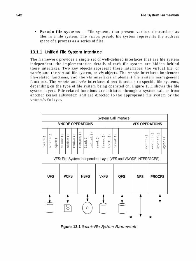
542 File System Framework
• Pseudo file systems — File systems that present various abstractions asfiles in a file system. The /proc pseudo file system represents the addressspace of a process as a series of files.
13.1.1 Unified File System Interface
The framework provides a single set of well-defined interfaces that are file systemindependent; the implementation details of each file system are hidden behindthese interfaces. Two key objects represent these interfaces: the virtual file, orvnode, and the virtual file system, or vfs objects. The vnode interfaces implementfile-related functions, and the vfs interfaces implement file system managementfunctions. The vnode and vfs interfaces direct functions to specific file systems,depending on the type of file system being operated on. Figure 13.1 shows the filesystem layers. File-related functions are initiated through a system call or fromanother kernel subsystem and are directed to the appropriate file system by thevnode/vfs layer.
Figure 13.1 Solaris File System Framework
System Call Interface
VFS: File-System-Independent Layer (VFS and VNODE INTERFACES)
UFS PCFS HSFS VxFS NFS PROCFS
rea
d()
write
()
op
en
()
clo
se()
mkd
ir()
rmd
ir()
ren
am
e()
link(
)
un
link(
)
see
k()
fsyn
c()
ioct
l()
cre
at(
)
mo
un
t()
um
ou
nt(
)
sta
tfs(
)
syn
c()
VNODE OPERATIONS VFS OPERATIONS
QFS

The vnode 543
13.1.2 File System Framework Facilities
The vnode/vfs interfaces—the “top end” of the file system module—implementvnode and vfs objects. The “bottom end” of the file system uses other kernel inter-faces to access, store, and cache the data they represent. Disk-based file systemsinterface to device drivers to provide persistent storage of their data, and theyinterface to network file systems access the networking subsystem to transmit andreceive data to remote systems. Pseudo file systems typically access local kernelfunctions and structures to gather the information they represent.
• Loadable file system modules — A dynamically loadable module type isprovided for Solaris file systems. File system modules are dynamically loadedat the time each file system type is first mounted (except for the root file sys-tem, which is mounted explicitly at boot).
• The vnode/vfs framework — As discussed, a unified interface frame-work that uses the vnode and vfs interfaces allows file functions and file sys-tem management functions to be implemented.
• File system caching — File systems that implement caching interface withthe HAT layer of the virtual memory system to map, unmap, and manage thememory used for caching. File systems use physical memory pages and theHAT layer of the virtual memory system to cache files. The kernel’s seg_mapdriver maps file system cache into the kernel’s address space when accessingthe file system through the read() and write() system calls.
• Path-name management — Files are accessed by means of path names,which are assembled as a series of directory names and file names. The filesystem framework provides routines that resolve and manipulate path namesby calling into the file system’s lookup() function to convert paths intovnode pointers.
• Directory name caching — A central directory name lookup cache (DNLC)provides a mechanism to cache pathname-to-vnode mappings, so that thedirectory components need not be read from disk each time they are needed.
13.2 The vnode
A vnode is a representation of a file in the Solaris kernel. The vnode is said to beobjectlike because it is an encapsulation of a file’s state and the methods that canbe used to perform operations on that file. A vnode represents a file within a filesystem; the vnode hides the implementation of the file system it resides in andexposes file system-independent data and methods for that file to the rest of thekernel.
A vnode object contains three important items (see Figure 13.2):

544 File System Framework
• File-system-independent data — Information about the vnode , such asthe type of vnode (file, directory, character device, etc.), flags that representstate, pointers to the file system that contains the vnode , and a referencecount that keeps track of how many subsystems have references to thevnode .
• Functions to implement file methods — A structure of pointers tofile-system-dependent functions to implement file functions such as open() ,close() , read() , and write() .
• File-system-specific data — Data that is used internally by each file sys-tem implementation; typically the in-memory inode that represents thevnode on the underlying file system. UFS uses an inode, NFS uses an rnode ,and tmpfs uses a tmpnode .
The kernel uses macros to call vnode functions. In that way, it can perform vnodeoperations (e.g., read() , write() , open() , close() ) without knowing what the
v_flags
struct vnode
v_typev_op..v_data
.
.
vop_link()
.
.
f_flag
struct inode
f_vnodef_offset
.
.
Figure 13.2 The Vnode Object
vop_open()
struct
vop_read()
vop_write()
vop_close()
vop_ioctl()
vop_create()
vnodeops
• VREG – Regu-lar File
• VDIR – Directory• VBLK – Block
Device• VCHR – Charac-
ter Device
(UFS inode shownin this example)

The vnode 545
underlying file system containing the vnode is. For example, to read from a filewithout knowing that it resides on a UFS file system, the kernel would simply callthe file-system-independent macro for read() , VOP_READ(), which would call thevop_read() method of the vnode , which in turn calls the UFS function,ufs_read() . A sample of a vnode macro from sys/vnode.h is shown below.
The structure of a vnode in Solaris can be found in sys/vnode.h and is shownbelow. It defines the basic interface elements and provides other information con-tained in the vnode .
13.2.1 vnode Types
Solaris has specific vnode types for files. The v_type field in the vnode structureindicates the type of vnode , as described in Table 13-1.
#define VOP_READ(vpp, mode, cr) \ (*(*(vpp))->v_op->vop_read)(vpp, mode, cr)
Header File <sys/vnode.h>
typedef struct vnode { kmutex_t v_lock; /* protects vnode fields */ ushort_t v_flag; /* vnode flags (see below) */ uint_t v_count; /* reference count */ struct vfs *v_vfsmountedhere; /* ptr to vfs mounted here */ struct vnodeops *v_op; /* vnode operations */ struct vfs *v_vfsp; /* ptr to containing VFS */ struct stdata *v_stream; /* associated stream */ struct page *v_pages; /* vnode pages list */ enum vtype v_type; /* vnode type */ dev_t v_rdev; /* device (VCHR, VBLK) */ caddr_t v_data; /* private data for fs */ struct filock *v_filocks; /* ptr to filock list */ struct shrlocklist *v_shrlocks; /* ptr to shrlock list */ kcondvar_t v_cv; /* synchronize locking */} vnode_t;
Header File <sys/vnode.h>
Table 13-1 Solaris 7 vnode Types from sys/vnode.h
Type DescriptionVNON No typeVREG Regular fileVDIR DirectoryVBLK Block deviceVCHR Character deviceVLNK Hard linkVFIFO Named pipeVDOOR Doors interfaceVPROC procfs node

546 File System Framework
13.2.2 Vnode Methods
The vnode interface provides the set of file system object methods, some of whichwe saw in Figure 13.1 on page 542. The file systems implement these methods toperform all file-system-specific file operations. Table 13-2 shows the vnode inter-face methods in Solaris.
VSOCK sockfs node (socket)VBAD Bad vnode
Table 13-2 Solaris 7 Vnode Interface Methods from sys/vnode.h
Method Descriptionvop_access() Checks access to the supplied vnode .vop_addmap() Increments the map count.vop_close() Closes the file given by the supplied vnode . When this is
the last close, some files systems use vop_close() toinitiate a writeback of outstanding dirty pages by check-ing the reference count in the vnode .
vop_cmp() Compares two vnode s.vop_create() Creates the supplied path name.vop_delmap() Decrements the map count.vop_dispose() Frees the given page from the vnode .vop_dump() Dumps data when the kernel is in a frozen state.vop_dumpctl() Prepares the file system before and after a dump.vop_frlock() Does file and record locking for the supplied vnode .vop_fsync() Flushes out any dirty pages for the supplied vnode .vop_getattr() Gets the attributes for the supplied vnode .vop_getpage() Gets pages in the range offset and length for the vnode
from the backing store of the file system. Does the realwork of reading a vnode . This method is often called as aresult of read() , which causes a page fault in seg_map,which calls vop_getpage .
vop_getsecattr() Gets security access control list attributes.vop_inactive() Frees resources and releases the supplied vnode . The file
system can choose to destroy the vnode or put it onto aninactive list, which is managed by the file system imple-mentation
vop_ioctl() Performs an I/O control on the supplied vnode .vop_fid() Gets a unique file ID for the supplied vnode . Used for
NFS client consistency.
Table 13-1 Solaris 7 vnode Types from sys/vnode.h (Continued)
Type Description

The vnode 547
vop_link() Creates a hard link to the supplied vnode .vop_lookup() Looks up the path name for the supplied vnode . The
vop_lookup() does file-name translation for the open ,stat system calls.
vop_map() Maps a range of pages into an address space by doing theappropriate checks and calling as_map() .
vop_mkdir() Makes a directory of the given name.vop_open() Opens a file referenced by the supplied vnode . The
open() system call has already done a vop_lookup()on the path name, which returned a vnode pointer andthen calls to vop_open() . This function typically doesvery little, since most of the real work was performed byvop_lookup() .
vop_pageio() Paged I/O support for file system swap files.vop_pathconf() Establishes file system parameters with the pathconf
system call.vop_poll() File system support for the poll() system call.vop_putpage() Writes pages in the range offset and length for the vnode
to the backing store of the file system. Does the real workof reading a vnode .
vop_read() Reads the range supplied for the given vnode .vop_read() typically maps the requested range of a fileinto kernel memory and then uses vop_getpage() to dothe real work.
vop_readdir() Reads the contents of a directory.vop_readlink() Follows the symlink in the supplied vnode .vop_realvp() Gets the real vnode from the supplied vnode .vop_remove() Removes the file for the supplied vnode .vop_rename() Renames the file to the new name.vop_rmdir() Removes a directory pointed to by the supplied vnode .vop_rwlock() Holds the reader/writer lock for the supplied vnode . This
method is called for each vnode , with the rwflag set to 0inside a read() system call and the rwflag set to 1inside a write() system call. POSIX semantics requireonly one writer inside write() at a time. Some file sys-tem implementations have options to ignore the writerlock inside vop_rwlock() .
vop_rwunlock() Releases the reader/writer lock for the supplied vnode .vop_seek() Seeks within the supplied vnode .vop_setattr() Sets the attributes for the supplied vnode .
Table 13-2 Solaris 7 Vnode Interface Methods from sys/vnode.h
Method Description

548 File System Framework
13.2.3 vnode Reference Count
A vnode is created by the file system at the time a file is first opened or createdand stays active until the file system decides the vnode is no longer needed. Thevnode framework provides an infrastructure that keeps track of the number of ref-erences to a vnode . The kernel maintains the reference count by means of theVN_HOLD() and VN_RELE() macros, which increment and decrement the v_countfield of the vnode . A vnode stays valid while its reference count is greater thanzero, so a subsystem can rely on a vnode ’s contents staying valid by callingVN_HOLD() before it references a vnode ’s contents. It is important to distinquish avnode reference from a lock; a lock ensures exclusive access to the data, and thereference count ensures persistence of the object.
When a vnode ’s reference count drops to zero, VN_RELE() invokes theVOP_INACTIVE() method for that file system. Every subsystem that references avnode is required to call VN_HOLD() at the start of the reference and to callVN_RELE() at the end of each reference. Some file systems deconstruct a vnodewhen its reference count falls to zero; others hold on to the vnode for a while sothat if it is required again, it is available in its constructed state. The UFS file sys-tem, for example, holds on to the vnode for a while after the last release so thatthe virtual memory system can keep the inode and cache for a file, whereas thePCFS file system frees the vnode and all of the cache associated with the vnode atthe time VOP_INACTIVE() is called.
13.2.4 Interfaces for Paging vnode Cache
Solaris unifies file and memory management by using a vnode to represent thebacking store for virtual memory. A page of memory represents a particular vnodeand offset. The file system uses the memory relationship to implement caching forvnode s within a file system. To cache a vnode , the file system has the memorysystem create a page of physical memory that represents the vnode and offset.
The virtual memory system provides a set of functions for cache managementand I/O for vnodes . These functions allow the file systems to cluster pages for I/O
vop_setfl() Sets file locks on the supplied vnode .vop_setsecattr() Sets security access control list attributes.vop_shrlock() ONC shared lock support.vop_space() Frees space for the supplied vnode .vop_symlink() Creates a symbolic link between the two path names.vop_write() Writes the range supplied for the given vnode . The
write system call typically maps the requested range ofa file into kernel memory and then uses vop_putpage()to do the real work.
Table 13-2 Solaris 7 Vnode Interface Methods from sys/vnode.h
Method Description

The vnode 549
and handle the setup and checking required for syncing dirty pages with theirbacking store. The functions, described in Table 13-3, set up pages so that they canbe passed to device driver block I/O handlers.
Table 13-3 Solaris 7 vnode Paging Functions from vm/pvn.h
Function Descriptionpvn_getdirty() Queries whether a page is dirty. Returns 1 if the
page should be written back (the iolock is held inthis case), or 0 if the page has been dealt with orhas been unlocked.
pvn_plist_init() Releases the iolock on each page and downgradesthe page lock to shared after new pages have beencreated or read.
pvn_read_done() Unlocks the pages after read is complete. The func-tion is normally called automatically bypageio_done() but may need to be called if anerror was encountered during a read.
pvn_read_kluster() Finds the range of contiguous pages within thesupplied address / length that fit within the pro-vided vnode offset / length that do not alreadyexist. Returns a list of newly created, exclusivelylocked pages ready for I/O. Checks that clusteringis enabled by calling the segop_kluster()method for the given segment.On return from pvn_read_kluster , the callertypically zeroes any parts of the last page that arenot going to be read from disk, sets up the readwith pageio_setup for the returned offset andlength, and then initiates the read withbdev_strategy() . Once the read is complete,pvn_plist_init( ) can release the I/O lock oneach page that was created.
pvn_write_done() Unlocks the pages after write is complete. Forasynchronous writes, the function is normallycalled automatically by pageio_done() when anasynchronous write completes. For synchronouswrites, pvn_write_done() is called afterpageio_done to unlock written pages. It may alsoneed to be called if an error was encountered dur-ing a write.

550 File System Framework
13.2.5 Block I/O on vnode Pages
The block I/O subsystem provides support for initiating I/O to and from vnodepages. Three functions, shown in Table 13-4, initiate I/O between a physical pageand a device.
13.3 The vfs Object
The vfs layer provides an administrative interface into the file system to supportcommands like mount and umount in a file-system-independent manner. The
pvn_write_kluster() Finds the contiguous range of dirty pages withinthe supplied offset and length. Returns a list ofdirty locked pages ready to be written back.On return from pvn_write_kluster() , the callertypically sets up the write with pageio_setup forthe returned offset and length, then initiates thewrite with bdev_strategy() . If the write is syn-chronous, then the caller should callpvn_write_done() to unlock the pages. If thewrite is asynchronous, then the io_done routinecalls pvn_write_done when the write is complete.
pvn_vplist_dirty() Finds all dirty pages in the page cache that havean offset greater than the supplied offset and callsthe supplied putapage() routine.pvn_vplist_dirty() is often used to synchro-nize all dirty pages for a vnode whenvop_putpage is called with a zero length.
Table 13-4 Solaris7 Paged I/O Functions from sys/bio.h
Function Descriptionbdev_strategy() Initiates an I/O on a page, using the block I/O
device.pageio_done() Waits for the block device I/O to complete.pageio_setup() Sets up a block buffer for I/O on a page of memory
so that it bypasses the block buffer cache by set-ting the B_PAGEIOflag and putting the page list onthe b_pages field.
Table 13-3 Solaris 7 vnode Paging Functions from vm/pvn.h (Continued)
Function Description

The vfs Object 551
interface achieves independence by means of a virtual file system (vfs ) object. Thevfs object represents an encapsulation of a file system’s state and a set of meth-ods for each of the file system administrative interfaces. Each file system type pro-vides its own implementation of the object. Figure 13.3 illustrates the vfs object.
Table 13-5 lists all the vfs interface methods.
Table 13-5 Solaris 7 vfs Interface Methods from sys/vfs.h
Method Descriptionvfs_mount() Mounts a file system on the supplied vnode .vfs_unmount() Unmounts the file system.vfs_root() Finds the root vnode for a file system.vfs_statvfs() Queries statistics on a file system.vfs_sync() Flushes the file system cache.vfs_vget() Finds a vnode that matches a unique file ID.vfs_mountroot() Mounts the file system on the root directory.vfs_swapvp() Not used.
vfs_next
struct vfs
vfs_fstypevfs_op..v_data
vfs_mountroot()
.
.
Figure 13.3 The vfs Object
vfs_mount()
struct
vfs_umount()
vfs_root()
vfs_statvfs()
vfs_sync()
vfs_vget()
vfsops
File-System-DependentData

552 File System Framework
The vfs interface, with the relevant data structures from sys/vfs.h , is shownbelow.
13.3.1 The File System Switch Table
The file system switch table, shown below, is a systemwide table of file systemtypes. Each file system type that is loaded on the system can be found in the vir-tual file system switch table. The file system switch table provides an ASCII list offile system names (e.g., ufs , nfs ), the initialization routines, and vfs object meth-
/ * Structure per mounted file system. Each mounted file system has * an array of operations and an instance record. * * The file systems are kept on a singly linked list headed by "rootvfs" and * terminated by NULL. File system implementations should not access this * list; it's intended for use only in the kernel's vfs layer. */typedef struct vfs { struct vfs *vfs_next; /* next VFS in VFS list */ struct vfsops *vfs_op; /* operations on VFS */ struct vnode *vfs_vnodecovered; /* vnode mounted on */ uint_t vfs_flag; /* flags */ uint_t vfs_bsize; /* native block size */ int vfs_fstype; /* file system type index */ fsid_t vfs_fsid; /* file system id */ caddr_t vfs_data; /* private data */ dev_t vfs_dev; /* device of mounted VFS */ ulong_t vfs_bcount; /* I/O count (accounting) */ ushort_t vfs_nsubmounts; /* immediate sub-mount count */ struct vfs *vfs_list; /* sync list pointer */ struct vfs *vfs_hash; /* hash list pointer */ ksema_t vfs_reflock; /* mount/unmount/sync lock */}
/* * Operations supported on virtual file system. */
typedef struct vfsops { int (*vfs_mount)(struct vfs *, struct vnode *, struct mounta *, struct cred *); int (*vfs_unmount)(struct vfs *, struct cred *); int (*vfs_root)(struct vfs *, struct vnode **); int (*vfs_statvfs)(struct vfs *, struct statvfs64 *); int (*vfs_sync)(struct vfs *, short, struct cred *); int (*vfs_vget)(struct vfs *, struct vnode **, struct fid *); int (*vfs_mountroot)(struct vfs *, enum whymountroot); int (*vfs_swapvp)(struct vfs *, struct vnode **, char *);}
Header File <sys/vfs.h>

The vfs Object 553
ods for that file system. The vfs_fstype field of the vfs object is an index intothe file system switch table.
File systems install entries into the file system switch table when they are firstloaded, usually during their initialization function. There is only one entry foreach type of file system, regardless of how many mounts exist for that type of filesystem. An example of the virtual file system switch table is shown below. Eachslot lists the name of the file system and tells where to find the relative functionsfor that file system.
To dump the vfs switch table, issue the crash command, as shown below.
The file system framework provides functions for accessing file systems in the filesystem switch table. These functions, described in Table 13-6, find file system
/* * File system type switch table. */typedef struct vfssw { char *vsw_name; /* type name string */ int (*vsw_init)(struct vfssw *, int); /* init routine */ struct vfsops *vsw_vfsops; /* file system operations vector */ int vsw_flag; /* flags */} vfssw_t;
Header File <sys/vfs.h>
struct vfssw vfssw[] = { "BADVFS", NULL, &vfs_strayops, 0, /* invalid */ "specfs", specinit, NULL, 0, /* SPECFS */ "ufs", ufsinit, &ufs_vfsops, 0, /* UFS */ "fifofs", fifoinit, &fifo_vfsops, 0, /* FIFOFS */ "namefs", namefsinit, &name_vfsops, 0, /* NAMEFS */ "proc", proc, &proc_vfsops, 0, /* PROCFS */ "s5fs", s5fsinit, &s5_vfsops, 0, /* S5FS */ "nfs", nfsinit, &nfs_vfsops, 0, /* NFS Ver 2 */ "hsfs", hsfsinit, &hs_vfsops, 0, /* HSFS */ "lofs", lofsinit, &lo_vfsops, 0, /* LOFS */ "tmpfs", tmpfsinit, &tmp_vfsops, 0, /* TMPFS */ "fd", fdinit, &fd_vfsops, 0, /* FDFS */ "pcfs", pcfsinit, &pc_vfsops, 0, /* PCFS */ "swapfs", swapinit, &swap_vfsops, 0, /* SWAPFS */};
# crashdumpfile = /dev/mem, namelist = /dev/ksyms, outfile = stdout> vfsswFILE SYSTEM SWITCH TABLE SIZE = 29SLOT NAME FLAGS 1 specfs 0 2 ufs 0 3 fifofs 0 4 namefs 0 5 proc 0 6 s5fs 0

554 File System Framework
entries, locate and load the file system modules for given types, and allocate newentries in the file system switch table.
13.3.2 The Mounted vfs List
The system starts with only one vfs object, the root file system, which is identi-fied by the rootvfs kernel pointer. You can subsequently mount file systems bylooking up the vfsops structure in the switch table and calling the mount opera-tion for that file system. The mount operation initializes a new vfs object andlinks it to the rootvfs object by using the vfs_next structure in the object. Eachtime a new file system is mounted, its vfs structure is linked onto the chain. You
Table 13-6 Solaris 7 vfs Support Functions from <sys/vfs.h>
Method Descriptiongetvfs() Gets a pointer to the vfs that matches the supplied
fsid . Used by the nfs server.vfs_getvfssw() Finds a vfssw entry by file system type name. Tries
to autoload the file system if entry is not found.allocate_vfssw() Allocates an entry in the file system switch table for
a given file type.

The vfs Object 555
can obtain a list of mounted file systems by starting at rootvfs and following thevfs -> vfs_next chain , as shown in Figure 13.4.
The file system framework provides functions, described in Table 13-7, for search-ing, adding, and removing file systems from the mounted file system list.
Table 13-7 Solaris 7 vfs Support Functions
Method Descriptionvfs_add() Called by a file system mount function to mount over
an existing mount point. For example, thevfs_mountroot() method uses this call to mountand unmount root.
vfs_remove() Removes a vfs object from the chain. Usually calledonly when unmounting a root overlay.
vfs_lock() Locks the entire file system.vfs_unlock() Unlocks the entire file system.
vfs_next
struct vfs
vfs_fstypevfs_op..v_data
ufs_mountroot()
.
.
Figure 13.4 The Mounted vfs List
ufs_mount()
struct
ufs_umount()
ufs_root()
ufs_statvfs()
ufs_sync()
ufs_vget()
vfsops * ufs_vfsops
vfs_next
struct vfs
vfs_fstypevfs_op..v_data
rootvfs
vfs_next
struct vfs
vfs_fstypevfs_op..v_data
nfs_mountroot()
.
.
nfs_mount()
struct
nfs_umount()
nfs_root()
nfs_statvfs()
nfs_sync()
nfs_vget()
vfsops * nfs_vfsops

556 File System Framework
vfs_make_fsid() Called by a file system to generate the file system IDfrom the device.
getvfs() Gets a pointer to the vfs that matches the suppliedfsid . Used only by the nfs server.
vf_to_stf() Maps vfs flags to statfs flags.
Table 13-7 Solaris 7 vfs Support Functions
Method Description

The vfs Object 557
To display the list of file system vfs objects, issue the crash or adb command, asshown below.
# crashdumpfile = /dev/mem, namelist = /dev/ksyms, outfile = stdout> vfs FSTYP BSZ MAJ/MIN FSID VNCOVERED PDATA BCOUNT FLAGS ufs 8192 118,104 1d80068 0 30000067888 0 notr lofs 8192 65,5 1040005 300032b99f8 300029265e0 0namefs 1024 179,0 2cc0000 300011ff5a0 300011ff440 0 nolnk lofs 8192 65,7 1040007 30002b0fb70 30002932978 0 lofs 8192 65,5 1040005 30000070958 30002932918 0 nfs 3276 175,2 2bc0002 30002b0e670 30002ecfe00 0 nosu hsfs 2048 91,1 31ba36b3 300013780a0 30001335e20 0 rd nfs 8192 175,1 2bc0001 30001378af0 300012e2200 0namefs 1024 179,0 2cc0000 30001139710 30000dde670 0 nolnk lofs 8192 65,57000 104dea8 30000070dd8 300001a8720 0 ufs 8192 65,57000 104dea8 30000d5fcd8 30000067348 0 notr tmpfs 8192 0,1 1 30000960ec0 300001260b0 0 notr fd 1024 172,0 2b00000 300009715d0 0 0 proc 512 168,0 2a00000 30000adb290 300009550c0 0> q# adb -k
$<vfslist
vfs 10458730root:root: next op vnodecovered 300031b2e90 ufs_vfsops 0root+0x18: flag bsize fstype 20 8192 2root+0x24: fsid data dev 1d8006800000002 30000067888 7600000068root+0x40: bcount nsubmounts list 0 19 0root+0x58: hash 0root+0x60: reflock
root+0x60: sleepq count 0 1
vfs 300031b2e90300031b2e90: next op vnodecovered 30001260cc8 lo_vfsops 300032b99f8300031b2ea8: flag bsize fstype 0 8192 10300031b2eb4: fsid data dev 104000500000002 300029265e0 4100000005300031b2ed0: bcount nsubmounts list 0 0 138b13500000000300031b2ee8: hash 0300031b2ef0: reflock
300031b2ef0: sleepq count 0 1

558 File System Framework
13.4 File System I/O
Two distinct methods perform file system I/O:
• read() , write() , and related system calls• Memory-mapping of a file into the process’s address space
Both methods are implemented the same way: a file is mapped into an addressspace and then paged I/O is performed on the pages within the mapped addressspace. Although it may be obvious that memory mapping is done when we mem-ory-map a file into a process’s address space, it is less obvious that the read() andwrite() system calls also map a file before reading or writing it. The major differ-ences between these two methods are where the file is mapped and who does themapping; a process calls mmap() to map the file into its address space for memorymapped I/O, and the kernel maps the file into the kernel’s address space for readand write. The two methods are contrasted in Figure 13.5.
mmap()
write()
File Segment
Paged VNODE VM Core
(File System Cache and Page Cache)
VNODE SegmentDriver (seg_map) Driver (seg_vn)
Binary (Text)
Stack
read()
Kernel AddressSpace
FileSystemseg_map
Process AddressSpace
Figure 13.5 The read()/write() vs. mmap() Methods for File I/O
Binary (Text)

File System I/O 559
13.4.1 Memory Mapped I/O
A request to memory-map a file into an address space is handled by the file sys-tem vnode method vop_map() and the seg_vn memory segment driver (see “Theseg_map Segment” on page 561). A process requests that a file be mapped into itsaddress space. Once the mapping is established, the address space represented bythe file appears as regular memory and the file system can perform I/O by simplyaccessing that memory.
Memory mapping of files hides the real work of reading and writing the filebecause the seg_vn memory segment driver quietly works with the file system toperform the I/Os without the need for process-initiated system calls. I/O is per-formed, in units of pages, upon reference to the pages mapped into the addressspace; reads are initiated by a memory access; writes are initiated as the VM sys-tem finds dirty pages in the mapped address space.
The system call mmap() calls the file system for the requested file with thevop_map() vnode method. In turn, the file system calls the address space mapfunction for the current address space, and the mapping is created. The protectionflags passed into the mmap() system call are reduced to the subset allowed by thefile permissions. If mandatory locking is set for the file, then mmap() returns anerror.
Once the file mapping is created in the process’s address space, file pages areread when a fault occurs in the address space. A fault occurs the first time a mem-ory address within the mapped segment is accessed because at this point, no phys-ical page of memory is at that location. The memory management unit causes ahardware trap for that memory segment; the memory segment calls its fault func-tion to handle the I/O for that address. The segvn_fault() routine handles a
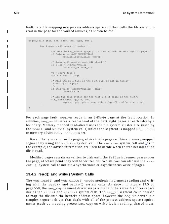
560 File System Framework
fault for a file mapping in a process address space and then calls the file system toread in the page for the faulted address, as shown below.
For each page fault, seg_vn reads in an 8-Kbyte page at the fault location. Inaddition, seg_vn initiates a read-ahead of the next eight pages at each 64-Kbyteboundary. Memory mapped read-ahead uses the file system cluster size (used bythe read() and write() system calls) unless the segment is mapped MA_SHAREDor memory advice MADV_RANDOM is set.
Recall that you can provide paging advice to the pages within a memory mappedsegment by using the madvise system call. The madvise system call and (as inthe example) the advise information are used to decide when to free behind as thefile is read.
Modified pages remain unwritten to disk until the fsflush daemon passes overthe page, at which point they will be written out to disk. You can also use the mem-cntl() system call to initiate a synchronous or asynchronous write of pages.
13.4.2 read() and write() System Calls
The vop_read() and vop_write() vnode methods implement reading and writ-ing with the read() and write() system calls. As shown in Figure 13.5 onpage 558, the seg_map segment driver maps a file into the kernel’s address spaceduring the read() and write() system calls. The seg_vn segment could be usedto map the file into the kernel’s address space; however, the seg_vn driver is acomplex segment driver that deals with all of the process address space require-ments (such as mapping protections, copy-on-write fault handling, shared mem-
segvn_fault (hat, seg, addr, len, type, rw) {
for ( page = all pages in region ) {
advise = lookup_advise (page); /* Look up madvise settings for page */ if (advise == MADV_SEQUENTIAL) free_all_pages_up_to (page);
/* Segvn will read at most 64k ahead */ if ( len > PVN_GETPAGE_SZ) len = PVN_GETPAGE_SZ;
vp = segvp (seg); vpoff = segoff (seg);
/* Read 64k at a time if the next page is not in memory, * else just a page */ if (hat_probe (addr+PAGESIZE)==TRUE) len=PAGESIZE;
/* Ask the file system for the next 64k of pages if the next*/ VOP_GETPAGE(vp, vp_off, len, &vpprot, plp, plsz, seg, addr + (vp_off - off), arw, cred) }}

File System I/O 561
ory, etc.), so a lighter-weight driver (seg_map) performs the mapping. The readand write file system calls require only a few basic mapping functions since theydo not map files into a process’s address space. Instead, they copy data to or fromthe process during a system call to a portion of the file that is mapped into the ker-nel’s address space by seg_map. The lighter-weight seg_map driver enhances per-formance by virtue of a shorter code path and reduced locking complexities.
13.4.3 The seg_map Segment
The seg_map segment maintains mappings of pieces of files into the kerneladdress space and is used only by the file systems. Every time a read or writesystem call occurs, the seg_map segment driver locates or creates a virtualaddress space where the page of the file can be mapped. Then, the system call cancopy the data to or from the user address space.
The seg_map segment provides a full set of segment driver interfaces (see“Memory Segments” on page 143); however, the file system directly uses a smallsubset of these interfaces without going through the generic segment interface.The subset handles the bulk of the work that is done by the seg_map segment forfile read and write operations. The functions used by the file systems are shown inTable 13-8.
At any time, the seg_map segment has some portion of the total file system cachemapped into the kernel address space. The maximum size of the seg_map seg-ment differs among hardware architectures, is often only a fraction of the totalphysical memory size, and contains only a small proportion of the total file systemcache. Note that even though the size of the seg_map segment is fixed, the pageswhich it references can be stolen by the page scanner, and as a result, only a por-tion of the seg_map segment may be resident (especially on machines where theseg_map segment is close to the size of physical memory).
A single seg_map segment is created at boot time. The segment is sized accord-ing to a table of machine types (see Table 13-9) and is capped at the amount of free
Table 13-8 seg_map Functions Used by the File Systems
Function Name Descriptionsegmap_getmap()segmap_getmapfault()
Retrieves or creates a mapping for a range ofthe file at the given offset and length.
segmap_release() Releases the mapping for a given file at agiven address.
segmap_pagecreate() Creates new page(s) of memory and slots inthe seg_map segment for a given file. Usedfor extending files or writing to holes during awrite.
segmap_pageunlock() Unlocks pages in the segment that was lockedduring segmap_pagecreate() .

562 File System Framework
memory just after the kernel has booted. For example, if the machine is an Ultra-1or sun4u architecture, the maximum size of the seg_map is 256 Mbytes. A64-Mbyte machine booting the Solaris kernel will most likely end up with aseg_map segment about 50 Mbytes in size, as 50 Mbytes was the free memorywhen the system was being booted. A 512-Mbyte sun4u system will have aseg_map size of 256 Mbytes, since free memory will be much larger than 256Mbytes while it is booting.
We can take a look at the seg_map segment on a running system by using adbwith the $seg macro, as shown below.
We can see that on this system, the segkmap segment has been created at boot as0x7432000 bytes, or 121,839,616 bytes. This system was a 128-Mbyte Ultra-1, andwe can see that free memory was smaller than the 256-Mbyte maximum segmentsize for the sun4u architecture. Hence, the segment was created at whatever thesize of free memory was at that point. Once segkmap is created, the segment inter-faces are called directly from the file system code during the read and write opera-tions.
The seg_map segment driver divides the segment into block-sized slots thatrepresent blocks in the files it maps. The seg_map block size for the Solaris kernelis 8,192 bytes. A 128-Mbyte segkmap segment would, for example, be divided into128-MB/8-KB slots, or 16,384 slots. The seg_map segment driver maintains a hashlist of its page mappings so that it can easily locate existing blocks. The list isbased on file and offsets. One list entry exists for each slot in the segkmap seg-
Table 13-9 Architecture-Specific Sizes of Solaris 7 seg_map Segment
Architecture Systems Maximum Size ofseg_map
sun4c SPARC 1, 2 4 Mbytessun4m SPARC 5, 10, 20 16 Mbytessun4d SPARC 1000,2000 32 Mbytessun4u UltraSPARC 256 Mbytes
# adb -k /dev/ksyms /dev/memphysmem 3b73
segkmap/Jsegkmap:segkmap: 3000022df50
3000022df50$<seg
3000022df50: base size as 2a750000000 7432000 104236e03000022df68: next prev ops 104234a0 3000022df88 segmap_ops3000022df80: data 300001b1d68

File System I/O 563
ment. The structure for each slot in a seg_map segment is defined in the<vm/segmap.h > header file, shown below.
The smap structures are:
• sm_vp — The file (vnode ) this slot represents (if slot not empty)• sm_hash , sm_next , sm_prev — Hash list reference pointers• sm_off — The file (vnode ) offset for a block-sized chunk in this slot in the
file• sm_bitmap — Bitmap to maintain translation locking• sm_refcnt — The number of references to this mapping caused by concur-
rent reads
The important fields in the smap structure are the file and offset fields, sm_vp andsm_off . These fields identify which page of a file is represented by each slot in thesegment.
/* * Each smap struct represents a MAXBSIZE-sized mapping to the * <sm_vp, sm_off> given in the structure. The location of * the structure in the array gives the virtual address of the * mapping. Structure rearranged for 64-bit sm_off. */struct smap { struct vnode *sm_vp; /* vnode pointer (if mapped) */
/* * These next 3 entries can be coded as * ushort_t’s if we are tight on memory. */ struct smap *sm_hash; /* hash pointer */ struct smap *sm_next; /* next pointer */ struct smap *sm_prev; /* previous pointer */ u_offset_t sm_off; /* file offset for mapping */
ushort_t sm_bitmap; /* bitmap for locked translations */ ushort_t sm_refcnt; /* reference count for uses */};
struct smfree { struct smap *sm_free; /* free list array pointer */
kmutex_t sm_mtx; /* protects smap data of this color */ kcondvar_t sm_free_cv; ushort_t sm_want; /* someone wants a slot of this color */};
Header File <vm/seg_map.h>

564 File System Framework
We can observe the seg_map slot activity with the kstat statistics that are col-lected for the seg_map segment driver. These statistics are visible with the net-stat command, as shown below.
Table 13-10 describes the segmap statistics.
# netstat -k segmapsegmap:fault 8366623 faulta 0 getmap 16109564 get_use 11723 get_reclaim 15257790 get_reuse825178get_unused 0 get_nofree 0 rel_async 710244 rel_write 749677 rel_free 16370rel_abort 0 rel_dontneed 709733 release 15343517 pagecreate 1009281
Table 13-10 Statistics from the seg_map Segment Driver
Field Name Descriptionfault The number of times segmap_fault was called, usually
as a result of a read or write system call.faulta The number of times the segmap_faulta function was
called. It is called to initiate asynchronous paged I/O on afile.
getmap The number of times the segmap_getmap function wascalled. It is called by the read and write system calls eachtime a read or write call is started. It sets up a slot in theseg_map segment for the requested range on the file.
get_use The number of times getmap found an empty slot in thesegment and used it.
get_reclaim The number of times getmap found a valid mapping forthe file and offset already in the seg_map segment.
get_reuse The number of times getmap deleted the mapping in anonempty slot and created a new mapping for the file andoffset requested.
get_unused Not used—always zero.get_nofree The number of times a request for a slot was made and
none was available on the internal free list of slots. Thisnumber is usually zero because each slot is put on the freelist when release is called at the end of each I/O. Hence,ample free slots are usually available.
rel_async The slot was released with a delayed I/O on it.rel_write The slot was released as a result of a write system call.rel_free The slot was released, and the VM system was told that
the page may be needed again but to free it and retain itsfile/offset information. These pages are placed on thecache list tail so that they are not the first to be reused.
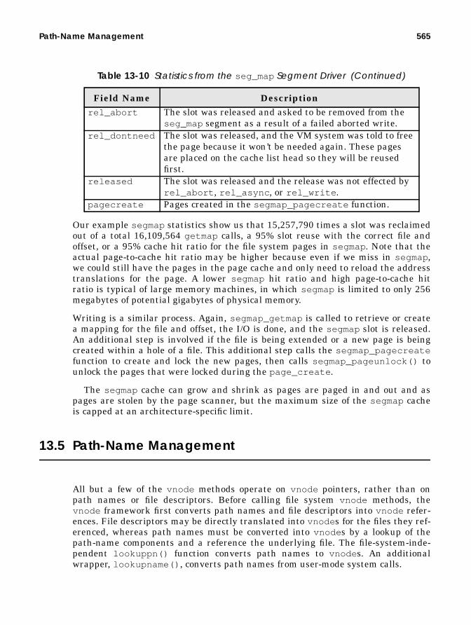
Path-Name Management 565
Our example segmap statistics show us that 15,257,790 times a slot was reclaimedout of a total 16,109,564 getmap calls, a 95% slot reuse with the correct file andoffset, or a 95% cache hit ratio for the file system pages in segmap. Note that theactual page-to-cache hit ratio may be higher because even if we miss in segmap,we could still have the pages in the page cache and only need to reload the addresstranslations for the page. A lower segmap hit ratio and high page-to-cache hitratio is typical of large memory machines, in which segmap is limited to only 256megabytes of potential gigabytes of physical memory.
Writing is a similar process. Again, segmap_getmap is called to retrieve or createa mapping for the file and offset, the I/O is done, and the segmap slot is released.An additional step is involved if the file is being extended or a new page is beingcreated within a hole of a file. This additional step calls the segmap_pagecreatefunction to create and lock the new pages, then calls segmap_pageunlock() tounlock the pages that were locked during the page_create .
The segmap cache can grow and shrink as pages are paged in and out and aspages are stolen by the page scanner, but the maximum size of the segmap cacheis capped at an architecture-specific limit.
13.5 Path-Name Management
All but a few of the vnode methods operate on vnode pointers, rather than onpath names or file descriptors. Before calling file system vnode methods, thevnode framework first converts path names and file descriptors into vnode refer-ences. File descriptors may be directly translated into vnode s for the files they ref-erenced, whereas path names must be converted into vnode s by a lookup of thepath-name components and a reference the underlying file. The file-system-inde-pendent lookuppn() function converts path names to vnode s. An additionalwrapper, lookupname() , converts path names from user-mode system calls.
rel_abort The slot was released and asked to be removed from theseg_map segment as a result of a failed aborted write.
rel_dontneed The slot was released, and the VM system was told to freethe page because it won’t be needed again. These pagesare placed on the cache list head so they will be reusedfirst.
released The slot was released and the release was not effected byrel_abort , rel_async , or rel_write .
pagecreate Pages created in the segmap_pagecreate function.
Table 13-10 Statistics from the seg_map Segment Driver (Continued)
Field Name Description
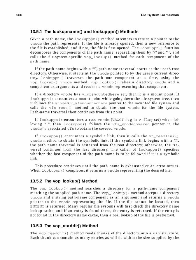
566 File System Framework
13.5.1 The lookupname() and lookupppn() Methods
Given a path name, the lookupppn() method attempts to return a pointer to thevnode the path represents. If the file is already opened, then a new reference tothe file is established, and if not, the file is first opened. The lookuppn() functiondecomposes the components of the path name, separating them by “/” and “.”, andcalls the file-system-specific vop_lookup() method for each component of thepath name.
If the path name begins with a “/”, path-name traversal starts at the user’s rootdirectory. Otherwise, it starts at the vnode pointed to by the user’s current direc-tory. lookuppn() traverses the path one component at a time, using thevop_lookup() vnode method. vop_lookup() takes a directory vnode and acomponent as arguments and returns a vnode representing that component.
If a directory vnode has v_vfsmountedhere set, then it is a mount point. Iflookuppn() encounters a mount point while going down the file system tree, thenit follows the vnode ’s v_vfsmountedhere pointer to the mounted file system andcalls the vfs_root() method to obtain the root vnode for the file system.Path-name traversal then continues from this point.
If lookuppn() encounters a root vnode (VROOTflag in v_flag set) when fol-lowing “..”, then lookuppn() follows the vfs_vnodecovered pointer in thevnode’s associated vfs to obtain the covered vnode .
If lookuppn() encounters a symbolic link, then it calls the vn_readlink()vnode method to obtain the symbolic link. If the symbolic link begins with a “/”,the path name traversal is restarted from the root directory; otherwise, the tra-versal continues from the last directory. The caller of lookuppn() specifieswhether the last component of the path name is to be followed if it is a symboliclink.
This procedure continues until the path name is exhausted or an error occurs.When lookuppn() completes, it returns a vnode representing the desired file.
13.5.2 The vop_lookup() Method
The vop_lookup() method searches a directory for a path-name componentmatching the supplied path name. The vop_lookup() method accepts a directoryvnode and a string path-name component as an argument and returns a vnodepointer to the vnode representing the file. If the file cannot be located, thenENOENTis returned. Many regular file systems will first check the directory namelookup cache, and if an entry is found there, the entry is returned. If the entry isnot found in the directory name cache, then a real lookup of the file is performed.
13.5.3 The vop_readdir() Method
The vop_readdir() method reads chunks of the directory into a uio structure.Each chunk can contain as many entries as will fit within the size supplied by the

Path-Name Management 567
uio structure. The uio_resid structure member shows the size of the getdentsrequest in bytes, which is divided by the size of the directory entry made by thevop_readdir() method to calculate how many directory entries to return.
Directories are read from disk with the buffered kernel file functions fbreadand fbwrite . These functions, described in Table 13-11, are provided as part ofthe generic file system infrastructure.
Table 13-11 Functions for Cached Access to Files from Within the Kernel
Function Name Descriptionfbread() Returns a pointer to locked kernel virtual address
for the given <vp , off > for len bytes. The readmay not cross a boundary of MAXBSIZE (8192)bytes.
fbzero() Similar to fbread() , but callssegmap_pagecreate() , not segmap_fault()so that SOFTLOCK can create the pages withoutusing VOP_GETPAGE(). Then, fbzero() zeroesup to the length rounded to a page boundary.
fbwrite() Direct write.fbwritei() Writes directly and invalidates pages.fbdwrite() Delayed write.fbrelse() Releases fbp .fbrelsei() Releases fbp and invalidate pages.

568 File System Framework
13.5.4 Path-Name Traversal Functions
Several path-name manipulation functions assist with decomposition of pathnames. The path-name functions use a path-name structure, shown below, to passaround path-name components.
The path-name functions are shown in Table 13-12.
13.5.5 The Directory Name Lookup Cache (DNLC)
The directory name lookup cache is based on BSD 4.2 code. It was ported to Solaris2.0 and threaded and has undergone some significant revisions. Most of theenhancements to the DNLC have been performance and threading, but a few visi-
/* * Path-name structure. * System calls that operate on path names gather the path name * from the system call into this structure and reduce it by * peeling off translated components. If a symbolic link is * encountered, the new path name to be translated is also * assembled in this structure. * * By convention pn_buf is not changed once it’s been set to point * to the underlying storage; routines which manipulate the path name * do so by changing pn_path and pn_pathlen. pn_pathlen is redundant * since the path name is null-terminated but is provided to make * some computations faster. */typedef struct pathname { char *pn_buf; /* underlying storage */ char *pn_path; /* remaining pathname */ size_t pn_pathlen; /* remaining length */ size_t pn_bufsize; /* total size of pn_buf */} pathname_t;
Header File <sys/pathname.h>
Table 13-12 Path-Name Traversal Functions from <sys/pathname.h>
Method Descriptionpn_alloc() Allocates a new path-name buffer.pn_get() Copies path-name string from user and mounts argu-
ments into a struct path name.pn_set() Sets a path name to the supplied string.pn_insert() Combines two path names.pn_getsymlink() Follows a symbolic link for a path name.pn_getcomponent() Extracts the next delimited path-name component.pn_setlast() Appends a component to a path name.pn_skipslash() Skips over consecutive slashes in the path name.pn_fixslash() Eliminates any trailing slashes in the path name.pn_free() Frees a struct path name.

Path-Name Management 569
ble changes are noteworthy. Table 13-13 summarizes the important changes to theDNLC.
13.5.5.1 DNLC Operation
Each time we open a file, we call the open() system call with a path name. Thatpath name must be translated to a vnode by the process of reading the directoryand finding the corresponding name that matches the requested name. No place inthe vnode stores the name of the file; so, to prevent us from having to reread thedirectory every time we translate the path name, we cache pathname-to-vnodemappings in the directory name lookup cache. The cache is managed as an LRUcache, so that most frequently used directory entries are kept in the cache. The
Table 13-13 Solaris DNLC Changes
Year OS Rev Comment1984 BSD 4.2 14-character name maximum1990 SunOS 2.0 31-character name maximum1994 SunOS 5.4 Performance (new locking/search algorithm)1998 SunOS 5.7 Variable name length

570 File System Framework
early-style DNLC in Solaris uses a fixed name length in the cache entries. Hence,if a file name is opened with a name larger than can fit, it will not be entered intothe DNLC. The old-style (pre-SunOS 5.4) DNLC is shown in Figure 13.6.
The number of entries in the DNLC is controlled by the ncsize parameter, whichis initialized to 4 * (max_nprocs + maxusers ) + 320 at system boot.
Most of the DNLC work is done with two functions: dnlc_enter() anddnlc_lookup() . When a file system wants to look up the name of a file, it firstchecks the DNLC with the dnlc_lookup() function, which queries the DNLC foran entry that matches the specified file name and directory vnode . If no entry isfound, dnlc_lookup fails and the file system reads the directory from disk. Whenthe file name is found, it is entered into the DNLC with the dnlc_enter() func-tion. The DNLC stores entries on a hashed list (nc_hash[] ) by file name anddirectory vnode pointer. Once the correct nc_hash chain is identified, the chain issearched linearly until the correct entry is found.
The original BSD DNLC had 8 nc_hash entries, which was increased to 64 inSunOS 4.x. Solaris 2.0 sized the nc_hash list at boot, attempting to make theaverage length of each chain no more than 4 entries. It used the total DNLC size,ncsize , divided by the average length to establish the number of nc_hashentries. Solaris 2.3 had the average length of the chain dropped to 2 in an attemptto increase DNLC performance; however, other problems, related to the LRU listlocking and described below, adversely affected performance.
nc_hash[]
dnlc_enter takesoldest nc’s from LRUdnlc_lookup
finds nc’s byhash lookup
newpath name
LRU List
vnodedir. vnode
char[31]
struct ncache
name
Figure 13.6 Solaris 2.3 Name Cache
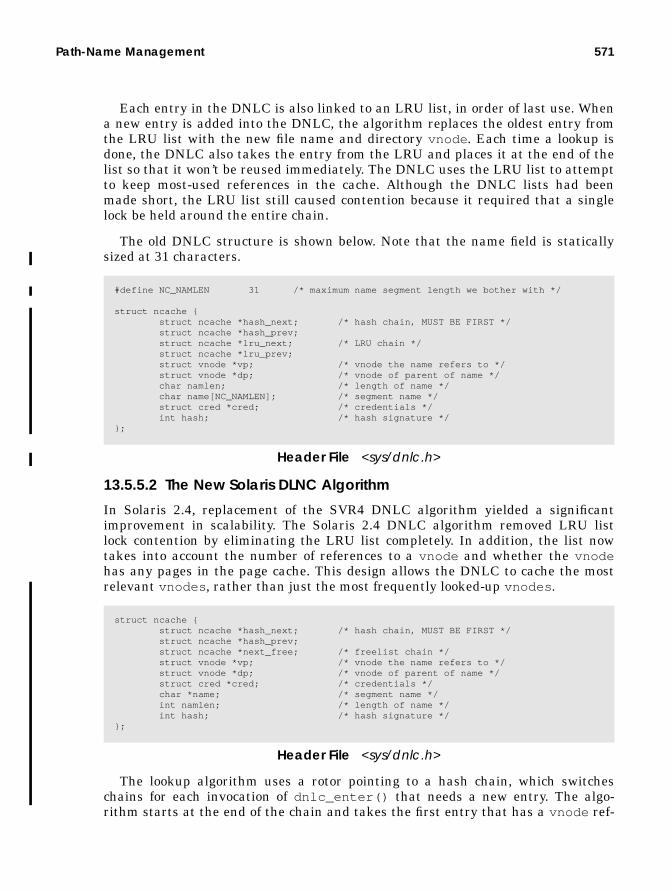
Path-Name Management 571
Each entry in the DNLC is also linked to an LRU list, in order of last use. Whena new entry is added into the DNLC, the algorithm replaces the oldest entry fromthe LRU list with the new file name and directory vnode . Each time a lookup isdone, the DNLC also takes the entry from the LRU and places it at the end of thelist so that it won’t be reused immediately. The DNLC uses the LRU list to attemptto keep most-used references in the cache. Although the DNLC lists had beenmade short, the LRU list still caused contention because it required that a singlelock be held around the entire chain.
The old DNLC structure is shown below. Note that the name field is staticallysized at 31 characters.
13.5.5.2 The New Solaris DLNC Algorithm
In Solaris 2.4, replacement of the SVR4 DNLC algorithm yielded a significantimprovement in scalability. The Solaris 2.4 DNLC algorithm removed LRU listlock contention by eliminating the LRU list completely. In addition, the list nowtakes into account the number of references to a vnode and whether the vnodehas any pages in the page cache. This design allows the DNLC to cache the mostrelevant vnodes , rather than just the most frequently looked-up vnodes .
The lookup algorithm uses a rotor pointing to a hash chain, which switcheschains for each invocation of dnlc_enter() that needs a new entry. The algo-rithm starts at the end of the chain and takes the first entry that has a vnode ref-
#define NC_NAMLEN 31 /* maximum name segment length we bother with */
struct ncache { struct ncache *hash_next; /* hash chain, MUST BE FIRST */ struct ncache *hash_prev; struct ncache *lru_next; /* LRU chain */ struct ncache *lru_prev; struct vnode *vp; /* vnode the name refers to */ struct vnode *dp; /* vnode of parent of name */ char namlen; /* length of name */ char name[NC_NAMLEN]; /* segment name */ struct cred *cred; /* credentials */ int hash; /* hash signature */};
Header File <sys/dnlc.h>
struct ncache { struct ncache *hash_next; /* hash chain, MUST BE FIRST */ struct ncache *hash_prev; struct ncache *next_free; /* freelist chain */ struct vnode *vp; /* vnode the name refers to */ struct vnode *dp; /* vnode of parent of name */ struct cred *cred; /* credentials */ char *name; /* segment name */ int namlen; /* length of name */ int hash; /* hash signature */};
Header File <sys/dnlc.h>

572 File System Framework
erence count of 1 or no pages in the page cache. In addition, during lookup, entriesare moved to the front of the chain so that each chain is sorted in LRU order. Fig-ure 13.7 illustrates the Solaris 2.4 DNLC.
The Solaris 7 DNLC was enhanced to use the kernel memory allocator to allocate avariable length string for the name; this change removed the 31-character limit. Inthe Solaris 7 DNLC structure, shown below, note that the name field has changedfrom a static structure to a pointer.
13.5.5.3 DNLC Support Functions
Table 13-14 lists the DNLC support functions.
Table 13-14 Solaris 7 DNLC Functions from sys/dnlc.h
Function Descriptiondnlc_lookup() Locates an ncache entry that matches the supplied
name and directory vnode pointer. Returns a pointerto the vnode for that entry or returns NULL.
dnlc_update() Enters a new ncache entry into the DNLC for thegiven name and directory vnode pointer. If an entryalready exists for the name and directory pointer butthe vnode is different, then the entry is overwritten.Otherwise, the function returns with no action.
nc_hash[]
dnlc_lookupfinds nc’s byhash lookup
vnodedir. vnode
char*
struct ncache
name
freelist rotor
DNLC entries aretaken from thefirst entry witha reference count=1,starting from the endof the chain
Figure 13.7 Solaris 2.4 DNLC
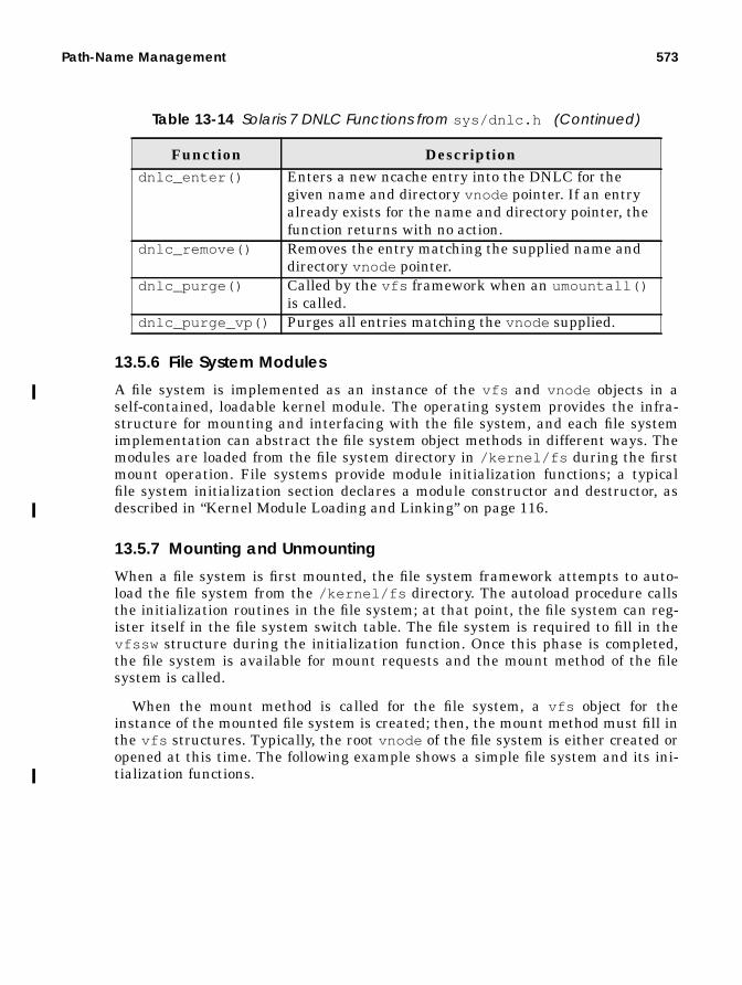
Path-Name Management 573
13.5.6 File System Modules
A file system is implemented as an instance of the vfs and vnode objects in aself-contained, loadable kernel module. The operating system provides the infra-structure for mounting and interfacing with the file system, and each file systemimplementation can abstract the file system object methods in different ways. Themodules are loaded from the file system directory in /kernel/fs during the firstmount operation. File systems provide module initialization functions; a typicalfile system initialization section declares a module constructor and destructor, asdescribed in “Kernel Module Loading and Linking” on page 116.
13.5.7 Mounting and Unmounting
When a file system is first mounted, the file system framework attempts to auto-load the file system from the /kernel/fs directory. The autoload procedure callsthe initialization routines in the file system; at that point, the file system can reg-ister itself in the file system switch table. The file system is required to fill in thevfssw structure during the initialization function. Once this phase is completed,the file system is available for mount requests and the mount method of the filesystem is called.
When the mount method is called for the file system, a vfs object for theinstance of the mounted file system is created; then, the mount method must fill inthe vfs structures. Typically, the root vnode of the file system is either created oropened at this time. The following example shows a simple file system and its ini-tialization functions.
dnlc_enter() Enters a new ncache entry into the DNLC for thegiven name and directory vnode pointer. If an entryalready exists for the name and directory pointer, thefunction returns with no action.
dnlc_remove() Removes the entry matching the supplied name anddirectory vnode pointer.
dnlc_purge() Called by the vfs framework when an umountall()is called.
dnlc_purge_vp() Purges all entries matching the vnode supplied.
Table 13-14 Solaris 7 DNLC Functions from sys/dnlc.h (Continued)
Function Description

574 File System Framework

Path-Name Management 575
extern struct mod_ops mod_fsops;static struct modlfs modlfs = { &mod_fsops, "vnode file pseudo file system", &vfw};
static struct modlinkage modlinkage = { MODREV_1, &modlfs, NULL};
int_init(void){ int error;
mutex_init(&vnfslock, NULL, MUTEX_DEFAULT, NULL); rw_init(&vnfsnodes_lock, NULL, RW_DEFAULT, NULL); error = mod_install(&modlinkage); if (error) { mutex_destroy(&vnfslock); rw_destroy(&vnfsnodes_lock); } myfs_init_otherstuff(); return (error);}
int_fini(void){ int error;
vnfs_vnlist_destroy(); error = mod_remove(&modlinkage); if (error) return (error); mutex_destroy(&vnfslock); rw_destroy(&vnfsnodes_lock); return (0);}
int_info(struct modinfo *modinfop){ return (mod_info(&modlinkage, modinfop));}
static struct vfssw vfw = { "myfs", myfsinit, &myfs_vfsops, 0};
static intmyfsinit(struct vfssw *vswp, int fstype){ vswp->vsw_vfsops = &myfs_vfsops; myfstype = fstype; (void) myfs_init(); return (0);}

576 File System Framework
13.6 The File System Flush Daemon
The fsflush process writes modified pages to disk at regular intervals. Thefsflush process scans through physical memory looking for dirty pages. When itfinds one, it initiates a write (or putpage ) operation on that page.
The fsflush process is launched by default every 5 seconds and looks for pagesthat have been modified (the modified bit is set in the page structure) more than30 seconds ago. If a page has been modified, then a page-out is scheduled for thatpage, but without the free flag so the page remains in memory. The fsflush dae-mon flushes both data pages and inodes by default. Table 13-15 describes theparameters that affect the behavior of fsflush .
Table 13-15 Parameters That Affect fsflush
Parameter Description Min Solaris 2.7Default
tune_t_fsflushr The number of seconds betweenfsflush scans.
1 5
autoup Pages older than autoup in sec-onds are written to disk.
1 30
doiflush By default, fsflush flushes bothinode and data pages. Set to 0 tosuppress inode updates.
0 1
dopageflush Set to 0 to suppress page flushes. 0 1

14
THE UNIX FILE SYSTEM
The Unix File System (UFS) is the general-purpose, disk-based file system thatis shipped with Solaris. It has been the standard disk-based file system since earlyversions of SunOS 4.x. Over the life of Solaris, UFS has undergone extensivechanges to keep pace with the required application performance, security, and reli-ability constraints.
14.1 UFS Development History
The original version of UFS is derived from the Berkeley Fast File System (FFS)work from BSD Unix, architected by Kirk McKusick and Bill Joy in the late eight-ies. The Berkeley FFS was the second major file system available for Unix and wasa leap forward from the original System V file system. The System V file systemwas lightweight and simple but had significant shortcomings: poor performance,unreliability, and lack of functionality.
During the development of SunOS 2.0, a file-system-independent interface wasintroduced to provide support for concurrent, different file systems within an oper-ating system instance. This interface, known today as the vnode /vfs interface, isthe mechanism all file systems use to interface with the file-related system calls.(The vnode /vfs architecture is discussed further in “The vnode” on page 543.) Atthat time, UFS was modified so that it could be used within the vnode /vfs frame-work. Since then, UFS has been the focus of much of the file system developmenteffort in Solaris.
577
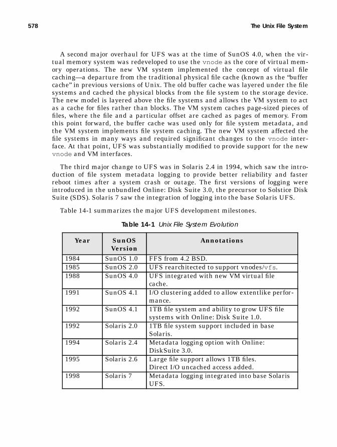
578 The Unix File System
A second major overhaul for UFS was at the time of SunOS 4.0, when the vir-tual memory system was redeveloped to use the vnode as the core of virtual mem-ory operations. The new VM system implemented the concept of virtual filecaching—a departure from the traditional physical file cache (known as the “buffercache” in previous versions of Unix. The old buffer cache was layered under the filesystems and cached the physical blocks from the file system to the storage device.The new model is layered above the file systems and allows the VM system to actas a cache for files rather than blocks. The VM system caches page-sized pieces offiles, where the file and a particular offset are cached as pages of memory. Fromthis point forward, the buffer cache was used only for file system metadata, andthe VM system implements file system caching. The new VM system affected thefile systems in many ways and required significant changes to the vnode inter-face. At that point, UFS was substantially modified to provide support for the newvnode and VM interfaces.
The third major change to UFS was in Solaris 2.4 in 1994, which saw the intro-duction of file system metadata logging to provide better reliability and fasterreboot times after a system crash or outage. The first versions of logging wereintroduced in the unbundled Online: Disk Suite 3.0, the precursor to Solstice DiskSuite (SDS). Solaris 7 saw the integration of logging into the base Solaris UFS.
Table 14-1 summarizes the major UFS development milestones.
Table 14-1 Unix File System Evolution
Year SunOSVersion
Annotations
1984 SunOS 1.0 FFS from 4.2 BSD.1985 SunOS 2.0 UFS rearchitected to support vnodes/vfs .1988 SunOS 4.0 UFS integrated with new VM virtual file
cache.1991 SunOS 4.1 I/O clustering added to allow extentlike perfor-
mance.1992 SunOS 4.1 1TB file system and ability to grow UFS file
systems with Online: Disk Suite 1.0.1992 Solaris 2.0 1TB file system support included in base
Solaris.1994 Solaris 2.4 Metadata logging option with Online:
DiskSuite 3.0.1995 Solaris 2.6 Large file support allows 1TB files.
Direct I/O uncached access added.1998 Solaris 7 Metadata logging integrated into base Solaris
UFS.

UFS On-Disk Format 579
14.2 UFS On-Disk Format
The on-disk format of the UFS file system has largely remained unchanged withthe introduction of new features, maintaining forward compatibility across allreleases. This allows Solaris to be upgraded without the need to back up andrestore file systems.
14.2.1 UFS Inodes
Information about which data blocks relate to each file are stored in a special fileindex node: the inode. The inode contains all of the information about the file,except for the file name, which is stored in the directory. Inode informationincludes:
• File type (regular, special, fifo, link, etc.)• Owner of file (uid )
• Group of file (gid )• File size• Attributes (read, execute, modify)• Timestamps (last modified, etc.)• Number of references to the file (links)
• Arrays of disk block addresses that contain the file’s data
14.2.2 UFS Directories
The file-name information and hierarchy information that constitute the directorystructure of UFS are stored in directories. Each directory stores a list of file namesand the inode number for each file; this information allows the directory structureto relate file names to real disk files.
The directory itself is stored in a file as a series of chunks, which are groups ofthe directory entries. Each directory entry in the chunk contains the followinginformation (see Figure 14.1):
• Inode number• Size of the file-name entry• Length of the directory entry• File-name string (null terminated)
Earlier file systems like the System V file system had a fixed directory recordlength, which meant that a lot of space would be wasted if provision was made forlong file names. In the UFS, each directory entry can be of variable length, thus

580 The Unix File System
providing a mechanism for long file names without wasting a lot of space. UFS filenames can be up to 255 characters long.
The group of directory chunks that constitute a directory is stored as a special typeof file. The notion of a directory as a type of file allows UFS to implement a hierar-chical directory structure: directories can contain files which are directories. Forexample, the root directory / has a name “/ ” and an inode number, 2, which holdsa chunk of directory entries holding a number of files and directories. One of thesedirectory entries, named etc , is another directory containing more files and direc-tories. For traversal up and down the file system, the chdir system call opens thedirectory file in question and then sets the current working directory to point tothe new directory file. Figure 14.2 illustrates the directory hierarchy.
2345 file15 1761 5 file216 16
inode
record
number(4 bytes)
length file-namestringlength(2 bytes)
file-namestring(null terminated)
rounded up to4 bytes(2 bytes)
Figure 14.1 UFS Directory Entry Format
inode = 2
etc optvar usr proc dev sbin tmp
passwd group hosts
inode=33
inode=154
inode=155
inode=205
..
/
Figure 14.2 Unix Directory Hierarchy

UFS On-Disk Format 581
Each directory contains two special files. The file named “.” is a link to the direc-tory itself; the file named “.. ” is a link to the parent directory. Thus, a change ofdirectory to .. leads to the parent directory.
14.2.3 UFS Hard Links
There is one inode for each file on disk; however, with hard links, each file canhave multiple file names. With hard links, file names in multiple directories pointto the same on-disk inode. The inode reference count field reflects the number ofhard links to the inode. Figure 14.3 illustrates inode 1423 describing a file; twoseparate directory entries with different names both point to the same inode num-ber. Note that the reference count, refcnt , has been incremented to 2.
Figure 14.3 UFS Links
14.2.4 UFS Layout
To avoid excessive seeking between data and inode information, UFS tries to placeinodes in close proximity to the data blocks for each file. The inodes are grouped atevenly spaced points across the file system in areas known as cylinder groups.Information about the location of each cylinder group is stored in the superblock,which is at the start of the file system. The on-disk layout of the UFS file system isshown in Figure 14.4.
/home/file1
/home/file2
size
atime
mtime
refcnt=2
.
.
inode=1423

582 The Unix File System
14.2.4.1 The Boot Block
At the start of the file system is the boot block. This is a spare sector reserved forthe boot program when UFS is used as a root file system. At boot time, the bootfirmware loads the first sector from the boot device and then starts executing coderesiding in that block. The firmware boot is file system independent, which meansthe boot firmware has no knowledge about the file system. We rely on code in thefile system boot block to do the mount of the root file system. When the systemstarts, the UFS boot block is loaded and executed, which, in turn, mounts the UFSroot file system. The boot program then passes control to a larger kernel loader, in/platform/sun4[mud]/ufsboot , to load the Unix kernel.
The boot program is loaded onto the first sector of the file system at install timewith the installboot (1M) command. The 512-byte install boot image resides in/usr/platform/sun4[mud]/lib/fs/ufs/bootblk in the platform-dependentdirectories.
Superblock
Cylinder Group
Boot Block
Data Block
Data Block
Data Block
Data Block
Superblock
Cylinder Group
Data Block
Data Block
Data Block
Data Block
Inodes contains blockdisk address pointers
Disk addresses are31-bit units of filesystem fragments. Theaddress is limited to2^31 x 1K for the default
Figure 14.4 UFS Layout
file system configuration,yielding a maximum filesize of 2 TB.
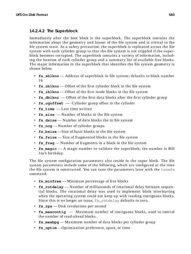
UFS On-Disk Format 583
14.2.4.2 The Superblock
Immediately after the boot block is the superblock. The superblock contains theinformation about the geometry and layout of the file system and is critical to thefile system state. As a safety precaution, the superblock is replicated across the filesystem with each cylinder group so that the file system is not crippled if the super-block becomes corrupted. The superblock contains a variety of information, includ-ing the location of each cylinder group and a summary list of available free blocks.The major information in the superblock that identifies the file system geometry isshown below.
• fs_sblkno — Address of superblock in file system; defaults to block number16
• fs_cblkno — Offset of the first cylinder block in the file system• fs_iblkno — Offset of the first inode blocks in the file system• fs_dblkno — Offset of the first data blocks after the first cylinder group• fs_cgoffset — Cylinder group offset in the cylinder• fs_time — Last time written• fs_size — Number of blocks in the file system• fs_dsize — Number of data blocks the in file system• fs_ncg — Number of cylinder groups• fs_bsize —Size of basic blocks in the file system• fs_fsize — Size of fragmented blocks in the file system• fs_frag — Number of fragments in a block in the file system• fs_magic — A magic number to validate the superblock; the number is Bill
Joy’s birthday.
The file system configuration parameters also reside in the super block. The filesystem parameters include some of the following, which are configured at the timethe file system is constructed. You can tune the parameters later with the tunefscommand.
• fs_minfree — Minimum percentage of free blocks• fs_rotdelay — Number of milliseconds of rotational delay between sequen-
tial blocks. The rotational delay was used to implement block interleavingwhen the operating system could not keep up with reading contiguous blocks.Since this is no longer an issue, fs_rotdelay defaults to zero.
• fs_rps — Disk revolutions per second• fs_maxcontig — Maximum number of contiguous blocks, used to control
the number of read-ahead blocks.• fs_maxbpg — Maximum number of data blocks per cylinder group• fs_optim —Optimization preference, space, or time

584 The Unix File System
14.2.5 Disk Block Location
The disk blocks for a file are represented by disk address pointers in the inode forthe file. Each inode has space for 12 disk block addresses, which, when used ontheir own, limit the maximum size of a file to 12 * 8K = 96K. To allow for largerfiles, indirect blocks provide more space for disk address blocks. With one level ofindirection, one of the disk addresses points to a file system block containing fur-ther disk addresses, greatly increasing the number of data blocks per file. A sec-ond level of indirection can also be used, allowing even more data blocks. The inodecontains a slot for triple indirect pointers, although triple indirection is currentlynot implemented within UFS. Figure 14.5 illustrates the inode format.
UFS allocates space, known as fragments, in file system blocks and subblocks.Assuming 8-Kbyte file system blocks:
.
.
2048 Slots
.
.
.
2048 Slots
.
.
.
2048 Slots
.
.
.
2048 Slots
.
Data
Data
Data Data
Data
Data
Data
Data
Data
Data
Data
Data
INODE
Mode, TimeOwnersetc...
12 Direct Blocks
Indirect BlocksDouble Indirect
Figure 14.5 The UFS inode Format

UFS On-Disk Format 585
• The first 12 direct blocks allow 12 blocks, or 98,304 bytes• The first level of indirection allows a full file system block of disk addresses,
which means that an 8-Kbyte block can hold 2,048 32-bit disk addresses; 12 +2048 blocks, or (12 + 2048) × 8 = 1,687,520 bytes.
• The second level of indirection (double indirect) allows 12 + 2048 + (2048 ×2048) × 8KB = 34,376,613,888 bytes.
There is, however, a limit to the maximum offset in each disk address, which isexpressed as a number of file system fragments; using the default fragments sizeof 1 Kbyte, the maximum offset for each block is 2^31 × 1KB = 2 terabytes.
14.2.6 UFS Block Allocation
UFS uses block sizes of 4 and 8 Kbytes, which provides significantly higher perfor-mance than the 512-byte blocks used in the System V file system. The downside oflarger blocks was that when partially allocated blocks occurred, several kilobytesof disk space for each partly filled file system block were wasted. To overcome thisdisadvantage, UFS uses the notion of file system fragments. Fragments allow asingle block to be broken up into 2, 4, or 8 fragments when necessary.
UFS block allocation tries to prevent excessive disk seeking by attempting toco-locate inodes within a directory and by attempting to co-locate a file’s inode andits data blocks. Where possible, all of the inodes in a directory are allocated in thesame cylinder group. This scheme helps reduce disk seeking when directories aretraversed; for example, executing a simple ls -l of a directory will access all ofthe inodes in that directory. If all the inodes reside in the same cylinder group,most of the data will be cached after the first few files are accessed. A directorywill be placed in a cylinder group different from that of its parent.
Blocks are allocated to a file sequentially, starting with the first 96 Kbytes (thefirst 12 direct blocks), skipping to the next cylinder group and allocating blocks upto the limit set by the file system parameter maxbpg, maximum-blocks-per-cylin-der-group. After that, blocks are allocated from the next available cylinder group.
By default, on a file system greater than 1 Gbyte, the algorithm allocates 96Kbytes in the first cylinder group, 16 Mbytes in the next available cylinder group,16 Mbytes from the next, and so on. The maximum cylinder group size is 54Mbytes, and the allocation algorithm only allows one-third of that space to be allo-cated to each section of a single file when it is extended. The maxbpg parameter isset to 2,048 8-Kbyte blocks by default at the time the file system is created; it isalso tunable but can only be tuned downward, since the maximum cylinder groupsize is 16-Mybte allocation per cylinder group.
Selection of a new cylinder group for the next segment of a file is governed by arotor and free-space algorithm. A per-file-system allocation rotor points to one ofthe cylinder groups; each time new disk space is allocated, it starts with the cylin-der group pointed to by the rotor. If the cylinder group has less than average free

586 The Unix File System
space, then it is skipped and the next cylinder group is tried. This algorithmmakes the file system attempt to balance the allocation across the cylinder groups.
14.2.7 UFS Allocation and Parameters
Figure 0.1 shows the default allocation that is used if a file is created on a largeUFS. The first 96 Kbytes of file 1 are allocated from the first cylinder group. Then,allocation skips to the second cylinder group and another 16 Mbytes of file 1 areallocated, and so on. When another file is created, we can see that it consumes theholes in the allocated blocks alongside file 1. There is room for a third file to do thesame.
Cyl
inde
r Gro
up
Cyl
inde
r Gro
up
54 MB 62 MB 78 MB 110 MB
file1file1 file1
file2file2
file3file3
Cyl
inde
r Gro
up
Figure 0.1 Default File Allocation in 16-Mbyte Groups

UFS On-Disk Format 587
The actual on-disk layout will not be quite as simple as the example shown butdoes reflect the allocation policies discussed. We can use an add-on tool, filestat ,to view the on-disk layout of a file, as shown below.
The filestat output shows that the first segment of the file occupies 192(512-byte) blocks, followed by the next 16 Mbytes, which start in a different cylin-der group. This particular file system was not empty when the file was created,which is why the next cylinder group chosen is a long way from the first.
We can observe the file system parameters of an existing file system with thefstyp command. The fstyp command simply dumps the superblock informationfor the file, revealing all of the cylinder group and allocation information. The fol-lowing example shows the output for a 4-Gbyte file system with default parame-ters. We can see that the file system has 8,247,421 blocks and has 167 cylinder
# /usr/local/bin/filestat testfileInodes per cyl group: 128Inodes per block: 64Cylinder Group no: 0Cylinder Group blk: 64File System Block Size: 8192Block Size: 512Number of 512b Blocks: 262288
Start Block End Block Length (512 byte Blocks)----------- ----------- ------------------------ 144 -> 335 192 400 -> 33167 32768 110800 -> 143567 32768 221264 -> 221343 80 221216 -> 221263 48 221456 -> 254095 32640 331856 -> 331999 144 331808 -> 331855 48 332112 -> 364687 32576 442448 -> 442655 208 442400 -> 442447 48 442768 -> 475279 32512

588 The Unix File System
groups spaced evenly at 6,272 (51-Mbyte) intervals. The maximum blocks to allo-cate for each group is set to the default of 2,048 8-Kbyte, 16 Mbytes.
# fstyp -v /dev/vx/dsk/homevol |moreufsmagic 11954 format dynamic time Sat Mar 6 18:19:59 1999sblkno 16 cblkno 24 iblkno 32 dblkno 800sbsize 2048 cgsize 8192 cgoffset 32 cgmask 0xffffffe0ncg 167 size 8378368 blocks 8247421bsize 8192 shift 13 mask 0xffffe000fsize 1024 shift 10 mask 0xfffffc00frag 8 shift 3 fsbtodb 1minfree 1% maxbpg 2048 optim timemaxcontig 32 rotdelay 0ms rps 120csaddr 800 cssize 3072 shift 9 mask 0xfffffe00ntrak 32 nsect 64 spc 2048 ncyl 8182cpg 49 bpg 6272 fpg 50176 ipg 6144nindir 2048 inopb 64 nspf 2nbfree 176719 ndir 10241 nifree 956753 nffree 21495cgrotor 152 fmod 0 ronly 0 logbno 0

UFS On-Disk Format 589
The UFS-specific version of the fstyp command dumps the superblock of a UFSfile system, as shown below.
# fstyp -v /dev/vx/dsk/homevol |moreufsmagic 11954 format dynamic time Sat Mar 6 18:19:59 1999sblkno 16 cblkno 24 iblkno 32 dblkno 800sbsize 2048 cgsize 8192 cgoffset 32 cgmask 0xffffffe0ncg 167 size 8378368 blocks 8247421bsize 8192 shift 13 mask 0xffffe000fsize 1024 shift 10 mask 0xfffffc00frag 8 shift 3 fsbtodb 1minfree 1% maxbpg 2048 optim timemaxcontig 32 rotdelay 0ms rps 120csaddr 800 cssize 3072 shift 9 mask 0xfffffe00ntrak 32 nsect 64 spc 2048 ncyl 8182cpg 49 bpg 6272 fpg 50176 ipg 6144nindir 2048 inopb 64 nspf 2nbfree 176719 ndir 10241 nifree 956753 nffree 21495cgrotor 152 fmod 0 ronly 0 logbno 0fs_reclaim is not setfile system state is valid, fsclean is 0blocks available in each rotational positioncylinder number 0: position 0: 0 4 8 12 16 20 24 28 32 36 40 44 48 52 56 60 64 68 72 76 80 84 88 92 96 100 104 108 112 116 120 124 position 2: 1 5 9 13 17 21 25 29 33 37 41 45 49 53 57 61 65 69 73 77 81 85 89 93 97 101 105 109 113 117 121 125 position 4: 2 6 10 14 18 22 26 30 34 38 42 46 50 54 58 62 66 70 74 78 82 86 90 94 98 102 106 110 114 118 122 126 position 6: 3 7 11 15 19 23 27 31 35 39 43 47 51 55 59 63 67 71 75 79 83 87 91 95 99 103 107 111 115 119 123 127cs[].cs_(nbfree,ndir,nifree,nffree): (23,26,5708,102) (142,26,5724,244) (87,20,5725,132) (390,69,5737,80) (72,87,5815,148) (3,87,5761,110) (267,87,5784,4) (0,66,5434,4) (217,46,5606,94) (537,87,5789,70) (0,87,5901,68) (0,87,5752,20)
.
.cylinders in last group 48blocks in last group 6144
cg 0:magic 90255 tell 6000 time Sat Feb 27 22:53:11 1999cgx 0 ncyl 49 niblk 6144 ndblk 50176nbfree 23 ndir 26 nifree 5708 nffree 102rotor 1224 irotor 144 frotor 1224frsum 7 7 3 1 1 0 9sum of frsum: 102iused: 0-143, 145-436free: 1224-1295, 1304-1311, 1328-1343, 4054-4055, 4126-4127, 4446-4447, 4455,4637-4638,

590 The Unix File System
14.3 UFS Implementation
UFS is implemented as a loadable file system module containing instances of thevfs and vnode objects. The UFS vnode interfaces implement file operations, andthe UFS vfs interfaces implement file system administration.
The UFS file system implementation can be divided into five major components:
• An instance of the vfs object and methods for mounting and unmounting afile system and gathering file system statistics
• An implementation of the vnode methods for file operations• A directory implementation that uses the standard directory name lookup
cache• A block map algorithm to map files to disk blocks on the storage device• An inode cache to keep vnodes in memory after they are no longer referenced
Figure 14.6 shows the relationship between the components of the UFS file sys-tem. UFS implements the vnode interface for file access and the vfs interface forfile system management. UFS interfaces with device drivers for persistent stor-age, the block buffer cache to store and retrieve metadata, the directory namelookup cache for caching path names, and the virtual memory system for cachingof file data.
In the following paragraphs, we discuss the implementation of each of theblocks within the UFS file system.
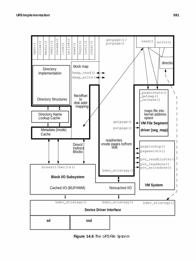
UFS Implementation 591
Directory NameLookup Cache
Block I/O Subsystem
VM File Segment
Device Driver Interface
driver (seg_map)
Directory Structures
Metadata (Inode)Cache
_pagecreate()
getpage()
bread()/bwrite()
read()
directio
write()
pagelookup()
pageexists()
bmap_read()
sd ssd
bdev_strategy()bdev_strategy()
bmap_write()
getpage()/
putpage()
file/offset
maps file intokernel addressspace
VM System
read/writesvnode pages to/from
disk
disk addrmapping
to
pvn_readdone()pvn_writedone()
pvn_readkluster()
Direct/IndirectBlocks
_getmap()_release()
Cached I/O (BUFHWM) Noncached I/O
op
en
()
clo
se()
mkd
ir()
rmd
ir()
ren
am
e()
link(
)
un
link(
)
see
k()
fsyn
c()
ioct
l()
cre
at(
)
block map
bdev_strategy()
DirectoryImplementation
putpage()
bdev_strategy()
Figure 14.6 The UFS File System

592 The Unix File System
14.3.1 Mapping of Files to Disk Blocks
At the heart of a disk-based file system are the block map algorithms, which imple-ment the on-disk file system format. These algorithms map UFS file and offsetspairs into disk addresses on the underlying storage. For UFS, two main func-tions—bmap_read() and bmap_write() —implement the on-disk format. Thesefunctions are called to do the following:
• bmap_read() queries the file system as to which physical disk sector a fileblock resides on; that is, requests a lookup of the direct/indirect blocks thatcontain the disk address(es) of the required blocks.
• bmap_write() allocates new disk blocks when extending or allocating blocksfor a file.
The bmap_read() function is used for both reading and writing to locate diskblocks; it accepts an inode and offset as input arguments, and a pointer to a diskaddress and length as output arguments.
The bmap_read() function is used for both file reads and writes. In both cases,the file system uses the bmap_read() algorithm to locate the physical blocks forthe file being read or written. The bmap_read() function searches though thedirect, indirect, and double indirect blocks of the inode to locate the disk address ofthe disk blocks that map to the supplied offset. The function also searches forwardfrom the offset, looking for disk blocks that continue to map contiguous portions ofthe inode, and returns the length of the contiguous segment in the length pointerargument. The length and the file system block clustering parameters are usedwithin the file system as bounds for clustering contiguous blocks to provide betterperformance by reading larger parts of a file from disk at a time.
The bmap_write() function allocates file space in the file system when a file isextended or a file with holes has blocks written for the first time. bmap_write()searches though the block free lists, using the rotor algorithm (discussed in “UFSBlock Allocation” on page 585), and updates the local, direct, and indirect blocks inthe inode for the file being extended.
14.3.1.1 Reading and Writing UFS Blocks
A file system read calls bmap_read() to find the location of the underlying physi-cal blocks for the file being read. UFS then calls the device driver’s strategy rou-
intbmap_read(struct inode *ip, u_offset_t off, daddr_t *dap, int *lenp)
Header File <fs/ufs_inode.h>
intbmap_write(struct inode *ip, u_offset_t off, int size, int alloc_only, struct cred *cr);
Header File <fs/ufs_inode.h>

UFS Implementation 593
tine for the device containing the file system to initiate the read operation bycalling bdev_strategy() .
A file system write operation that extends a file first calls bmap_write() to allo-cate the new blocks and then calls bmap_read() to obtain the block location forthe write. UFS then calls the device driver’s strategy routine, by means ofbdev_strategy() , to initiate the file write.
14.3.1.2 Buffering Block Metadata
The block map functions access metadata (local/direct and double indirect blocks)on the device media through the buffer cache, using the bread() and bwrite()buffered block I/O kernel functions. The block I/O functions read and write deviceblocks in 512-byte chunks, and they cache physical disk blocks in the block buffercache (note: this cache is different from the page cache, used for file data). TheUFS file system requires 1 Mbyte of metadata for every 2 Gbytes of file space. Thisrelationship can be used as a rule to calculate the size of the block buffer cache, setby the bufhwm kernel parameter.
14.3.2 Methods to Read and Write UFS Files
Files can be read or written in two ways: by the read() or write() system calls,or by mapped file I/O. The read() and write() system calls call the file system’svop_read() and vop_write() method. These methods map files into the ker-nel’s address space and then use the file system’s vop_getpage() andvop_putpage() methods to transfer data to and from the physical media.
14.3.2.1 ufs_read()
An example of the steps taken by a UFS read system call is shown in Figure 14.7.A read system call invokes the file-system-dependent read function, which turnsthe read request into a series of vop_getpage() calls by mapping the file into thekernel’s address space with the segmap driver, as described in “File System I/O” onpage 558.
The vop_read method calls into the seg_map segment to create a virtual addressin the kernel address space for the file and offset requested with thesegmap_getmap() function. The seg_map driver determines whether it alreadyhas a slot for the page of the file at the given offset by looking into its hashed list ofmapping slots. Once a slot is located or created, an address for the page is created,and a page fault for the page that is mapping the file is initiated to read in page atthe virtual address of the seg_map slot. The page fault is initiated while we arestill in the segmap_getmap() routine, by a call to segmap_fault() , which inturn calls back into the file system with vop_getpage() , which callsufs_getpage() .
The ufs_getpage() routine handles the task of bringing the requested rangeof the file (vnode , offset, and length) from disk into the virtual address and lengthpassed into the ufs_getpage() function. The ufs_getpage() function locates

594 The Unix File System
read(myfile, 16384)
16K of heap spacein process
User Process Address Space Kernel Address Space
read() ufs_read
1. ufs_read asks seg_map
16K of file inkernel addressspace
3a. If seg_map finds the pages
6. UFS copies the 16K offile data from the kerneladdress space to useraddress space.
2. seg_map checks to see if
for a kernel mapping forthe requested range.
the requested range is alreadymapped into the kernelseg_map segment.
already mapped into kernel,then it simply returns theaddress.
3b. If seg_map does not findthat the pages are mapped,it creates a mapping and thencalls ufs_getpage to bring inthe pages.
4. The page cache is checked tosee if it has the requested pages.
5a. If ufs_getpage finds thepages in page cache, then itsimply returns to seg_map.
5b. If ufs_getpage does nothave the pages, then it asksufs_bmap for the disk addressof the pages and brings themin from storage.
7. seg_map releases thevirtual address space onto itsfree-list.
First-level page cache,256 MB on Ultra
Second-level page cache,(dynamic)
Figure 14.7 ufs_read()
UFS Implementation 595
the file’s blocks (through the block map functions discussed in “Mapping of Files toDisk Blocks” on page 592) and reads them by calling the underlying device’s strat-egy routine.
Once the page is read by the file system, the requested range is copied back tothe user by the uio_move() function. Then, the file system releases the slot asso-ciated with that block of the file with the segmap_release() function. At thispoint, the slot is not removed from the segment because we may need the same fileand offset later (effectively caching the virtual address mapping); instead, it isadded onto a seg_map free list so it can be reclaimed or reused later.
14.3.2.2 ufs_write()
Writing to the file system is performed in a similar manner, although it is morecomplex because of some of the file system write performance enhancements, suchas delayed writes and write clustering. Writing to the file system follows the stepsshown in Figure 14.8.
The write system call calls the file-system-independent write, which in ourexample calls ufs_write() . UFS breaks the write into 8-Kbyte chunks and thenprocesses each chunk. For each 8-Kbyte chunk, the following steps are performed.
• UFS asks the segmap driver for an 8-Kbyte mapping of the file in the ker-nel’s virtual address space. The page for the file and offset is mapped here sothat the data can be copied in and then written out with paged I/O.
• The segmap segment looks in its cache of mappings. If a mapping exists, it isreturned. If there is no mapping for this file and offset, then a new one is cre-ated by replacement of one of the existing mappings.
• If the write is to a whole file system block, then a new zeroed page is createdwith segmap_pagecreate() . In the case of a partial block write, the blockmust first be read in so the partial block contents can be replaced.
• The new page is returned, locked, to UFS. The buffer that is passed into thewrite system call is copied from user address space into kernel address space.
• The ufs_write throttle first checks to see if too many bytes are outstandingfor this file as a result of previous delayed writes. If more than the kernelparameter ufs_HW bytes are outstanding, the write is put to sleep until theamount of outstanding bytes drops below the kernel parameter ufs_LW .
• The file system calls the seg_map driver to map in the portion of the file weare going to write. The data is copied from the process’s user address spaceinto the kernel address space allocated by seg_map, then seg_map is calledto release the address space containing the dirty pages to be written. This iswhen the real work of write starts, because seg_map calls ufs_putpage()when it realizes there are dirty pages in the address space it is releasing.

596 The Unix File System
write(myfile, 16384)
16K of heap spacein process
User Process Address Space Kernel Address Space
write() ufs_write()
1. UFS write maps the fileinto kernel address spacevia seg_map.
16K of file inkernel addressspace
3. UFS copies the 16K offile data from the useraddress space to kerneladdress space.
4.UFS then releases the16K of kernel address spaceonto the seg_map freelist. At this point, seg_mapcalls ufs_putpage to writethe data out.
5a. ufs_putpage puts thepage into a cluster. If thecluster is full (cluster sizeis determined by maxcontig),then ufs_putpage pushes the cluster;otherwise, it leaves the pagethere for a delayed write.
5b. ufs_putpage writesthe page to disk (waits
AsyncWrite
SyncWrite
6. segmap_releasereturns control tothe caller.
for I/O to complete).
2.UFS write throttle: If thereare more than ufs_HW bytesoutstanding, then the writeis throttled.
Figure 14.8 ufs_write()

UFS Implementation 597
14.3.3 In-Core UFS Inodes
Each file system has two forms of an inode: the in-core (in-memory) inode and theon-disk inode. The on-disk inode resides on the physical medium and representsthe on-disk format and layout of the file; the in-core inode contains resides in mem-ory and contains the file-system-dependent information, kernel locks, and state.
The vnode is typically contained in an in-core inode, so that when an inode iscreated, a vnode is automatically created. In that way, simple macros can convertfrom a file-system-dependent inode to a file-system-independent vnode . Thein-core UFS inode contains an embedded vnode , as shown in Figure 14.9.
Embedding the vnode in the inode also allows file systems to easily convertbetween inode and vnode references. File systems use macros to convert a vnodereference to an inode reference, and vice versa. UFS uses the macro VTOI to con-
.
.
i_chain[2]
struct inode
i_ic
Figure 14.9 The UFS inode
v_flags
struct vnode
v_typev_opv_data..
i_devvpi_devi_diroffi_ufsvfs..
i_vnode
struct ufsvfs

598 The Unix File System
vert a vnode pointer to an inode pointer, and the macro ITOV to convert an inodepointer to a vnode pointer.
14.3.3.1 Freeing inodes—the Inode Idle List
When the last reference to a vnode is released, the vop_inactive() routine forthe file system is called. (See vnode reference counts in “vnode Reference Count”on page 548.) UFS uses vop_inactive() to free the inode when it is no longerrequired. UFS implements an idle list because if we were to destroy each vnodewhen the last reference to a vnode is relinquished, we would throw away all thedata relating to that vnode , including all of the file pages cached in the pagecache. This practice could mean that if a file is closed and then reopened, none ofthe file data that was cached would be available after the second open and wouldneed to be reread from disk.
14.3.3.2 Caching Inodes—the Inode Idle List
Each time the last reference to a file is made, the vop_inactive() method for thefile system is called to handle the last reference to the vnode . UFS implements anidle queue to cache recently closed inodes in their constructed state, to keep theirin-kernel state and file system cache pages intact.
For idling inodes, UFS implements a thread that maintains a list of idle inodeson a queue. The ufs_inactive() routine puts UFS inodes into the idle queue.The ufs_inactive() routine is passed a vnode , and the UFS uses the VTOImacro to convert an inode reference, which is then placed onto the idle queue. Theinodes on the idle queue retain all of their state, keeping any pages in the pagecache in memory. The inodes stay on the idle queue until the idle queue reaches ahigh watermark, at which point the UFS idle thread is awakened to free half of theinode idle queue. Figure 14.10 illustrates the process.
/* * Convert between inode pointers and vnode pointers */#define VTOI(VP) ((struct inode *)(VP)->v_data)#define ITOV(IP) ((struct vnode *)&(IP)->i_vnode)
Header File <fs/ufs_inode.h>

UFS Implementation 599
Figure 14.10 UFS Idle Queue
The ufs_inactive() routine attempts to free inodes with no pages in the pagecache in preference to inodes that still have pages in the page cache. The goal—tokeep as many file pages in the page cache as possible—is realized by the followingprocedure: inodes that have pages associated with them are placed at the tail ofthe idle queue, and inodes with no pages are placed at the head of the inode queue.When inodes are removed from the idle queue, they are removed from the tail ofthe queue, that is, the inodes without pages are taken first.
The UFS idle thread is awakened when the size of the idle queue exceedsone-fourth of the system-tunable parameter ufs_ninode . When the thread wakesup, it attempts to remove half the inodes from the idle queue, to discard all of thepages associated with the inode, and to free the kernel memory used to store thein-memory inode. Inodes that are removed from the idle queue update kernel sta-
# sar -g 3 3333
SunOS devhome 5.7 Generic sun4u 08/01/99
09:42:52 pgout/s ppgout/s pgfree/s pgscan/s %ufs_ipf09:42:55 0.00 0.00 30.90 0.00 0.0009:42:58 0.00 0.00 34.55 0.00 0.0009:43:01 0.00 0.00 45.15 0.00 0.0009:43:04 0.00 0.00 64.00 0.00 0.0009:43:07 0.00 0.00 69.44 0.00 0.0009:43:10 0.00 0.00 84.95 0.00 1.2109:43:13 0.00 0.00 86.67 0.00 0.0009:43:16 0.00 0.00 35.88 0.00 0.0009:43:19 0.00 0.00 71.33 0.00 0.00
ufs_inactive()
inodes with pagesinodes without pages
UFS idle queue (tail)
(head)
free inode resources
queue size target isufs_ninode / 4
UFS idle thread wakes up whenqueue size is ufs_ninode / 4 andfrees 1/2 of queue

600 The Unix File System
tistics in the virtual memory system; you can obtain the statistics with sar . Thestatistics show how many inodes that have pages associated with them in the pagecache were freed. Note that the %ufs_ipf column in the sar output for this exam-ple shows that almost no inodes that are freed had associated pages.
14.3.4 UFS Directories and Path Names
The file system directory and path-name code are responsible for managing theon-disk directory format and translating file-name lookups into vnode references.Four vnode methods implement directory and path-name services:vop_lookup() , vop_readdir() , vop_mkdir() , and vop_rmdir() .
Path names are converted to vnode references by the file-system-independentlookuppn() function. The lookuppn() function calls into the file system’svop_lookup() method. Directories are traversed by means of thevop_readdir() method; they are created and deleted with the vop_mkdir() andvop_rmdir() methods.
14.3.4.1 ufs_lookup()
The ufs_lookup() function traverses the directory to find a file matching thesupplied path name and returns a reference to a vnode for the file. For example,the open system call for a UFS file translates the path name of the file into avnode by calling lookuppn() , which calls ufs_lookup() for each component ofthe path name. Opening /etc/passwd causes vop_lookup() to be called for theroot directory / , the etc subdirectory, and the password file passwd .
The ufs_lookup() implementation first searches the directory name lookupcache (DNLC), using dnlc_lookup() , to check if an entry exists in the DNLC. Ifnot, the directory is read in and searched for the path name. Once located, thepath name is entered into the DNLC with dnlc_enter() , and an open vnode isreturned to the caller.
14.3.4.2 ufs_readdir()
The ufs_readdir() method reads chunks of UFS directories from disk andreturns them to the caller. The ufs_readdir() method is typically called as aresult of the readdir() system call. The raw UFS directory data is cached in thefile system cache (compared with the DNLC, which caches the inode and pathname information for individual files).

15
SOLARIS FILE SYSTEMCACHE
One of the most important features of a file system is its ability to cache filedata, but, ironically, the file system cache is not implemented in the file system. InSolaris, the file system cache is implemented in the virtual memory system. In thissection, we explain how Solaris file caching works, and we explore the interactionsbetween the file system cache and the virtual memory system.
15.1 Introduction to File Caching
Traditional Unix implements file system caching in the I/O subsystem by keepingcopies of recently read or written blocks in a block cache. This block cache sits justabove the disks, and it caches data corresponding to physical disk sectors.
Figure 15.1 shows an example in which a process reads a piece of a file. The pro-cess reads a segment of a file by issuing a read system call into the operating sys-tem. The file system must then look up the corresponding disk block for the file bylooking up the block number in the direct/indirect blocks for that file, after whichthe files system requests that block from the I/O system. The I/O system retrievesthe block from disk the first time; then, the file systems satisfies subsequent readsby reading the disk block from the block buffer cache. Note that even though thedisk block is cached in memory—because this is a physical block cache—we haveto invoke the file system and look up the physical block number for every cachedread.
601

602 Solaris File System Cache
Typically, the old buffer cache is sized statically by a kernel configuration parame-ter. Changing the size of the buffer cache requires a kernel rebuild and a reboot.
15.1.1 Solaris Page Cache
Solaris has a new method, the page cache, of caching file system data. The pagecache was developed at Sun as part of the virtual memory rewrite in SunOS 4 in1985 and is used by System V Release 4 Unix. Page cache derivatives are now alsoused in Linux and Windows NT. The page cache has two major differences fromthe old caching method. First, it’s dynamically sized and can use all memory thatis not being used by applications. Second, it caches file blocks rather than diskblocks. The key difference is that the page cache is a virtual file cache rather thana physical block cache. A virtual file cache allows the operating system to retrievefile data by simply looking up the file reference and seek offset. The old way, theoperating system invoked the file system, which looked up the physical disk blocknumber corresponding to the file and retrieved that block from the physical blockcache. The virtual file cache is far more efficient.
File System
Read (file, offset)
Disk
Logical
Process
Physical Read (device, sector #)
Block Buffer Cache
Disk Block (device, sector #)
User Process
Kernel
Figure 15.1 The Old-Style Buffer Cache
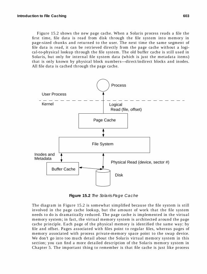
Introduction to File Caching 603
Figure 15.2 shows the new page cache. When a Solaris process reads a file thefirst time, file data is read from disk through the file system into memory inpage-sized chunks and returned to the user. The next time the same segment offile data is read, it can be retrieved directly from the page cache without a logi-cal-to-physical lookup through the file system. The old buffer cache is still used inSolaris, but only for internal file system data (which is just the metadata items)that is only known by physical block numbers—direct/indirect blocks and inodes.All file data is cached through the page cache.
Figure 15.2 The Solaris Page Cache
The diagram in Figure 15.2 is somewhat simplified because the file system is stillinvolved in the page cache lookup, but the amount of work that the file systemneeds to do is dramatically reduced. The page cache is implemented in the virtualmemory system; in fact, the virtual memory system is architected around the pagecache principle. Each page of the physical memory is identified the same way: byfile and offset. Pages associated with files point to regular files, whereas pages ofmemory associated with process private-memory space point to the swap device.We don’t go into too much detail about the Solaris virtual memory system in thissection; you can find a more detailed description of the Solaris memory system inChapter 5. The important thing to remember is that file cache is just like process
File System
Read (file, offset)
Disk
Logical
Process
Physical Read (device, sector #)
User Process
Kernel
Page Cache
Buffer Cache
Inodes andMetadata

604 Solaris File System Cache
memory, and as we will see, file caching shares the same paging dynamics as therest of the memory system.
15.1.2 Block Buffer Cache
The old buffer cache is used in Solaris for caching of inodes and file metadata andis now also dynamically sized. In old versions of Unix, the buffer cache was fixed insize by the nbuf kernel parameter, which specified the number of 512-byte buff-ers. We now allow the buffer cache to grow by nbuf , as needed, until it reaches aceiling specified by the bufhwm kernel parameter. By default, the buffer cache isallowed to grow until it uses 2 percent of physical memory. We can look at theupper limit for the buffer cache by using the sysdef command.
Now that we only keep inode and metadata in the buffer cache, we don’t need avery large buffer. In fact, we only need 300 bytes per inode and about 1 megabyteper 2 gigabytes of files that we expect to be accessed concurrently (note that thisrule of thumb is for UFS file systems).
For example, if we have a database system with 100 files totaling 100 gigabytesof storage space and we estimate that we will access only 50 gigabytes of thosefiles at the same time, then at most we would need 100 × 300 bytes = 30 kilobytesfor the inodes, and about 50 / 2 * 1 megabyte = 25 megabytes for the metadata(direct and indirect blocks). On a system with 5 gigabytes of physical memory, thedefaults for bufhwm would provide us with a bufhwm of 102 megabytes, which ismore than sufficient for the buffer cache. If we are really memory misers, we couldlimit bufhwm to 30 megabytes (specified in kilobytes) by setting the bufhwmparameter in the /etc/system file. To set bufhwm smaller for this example, wewould put the following line into the /etc/system file.
You can monitor the buffer cache hit statistics by using sar -b . The statistics forthe buffer cache show the number of logical reads and writes into the buffer cache,
# sysdef** Tunable Parameters* 7757824 maximum memory allowed in buffer cache (bufhwm) 5930 maximum number of processes (v.v_proc) 99 maximum global priority in sys class (MAXCLSYSPRI) 5925 maximum processes per user id (v.v_maxup) 30 auto update time limit in seconds (NAUTOUP) 25 page stealing low water mark (GPGSLO) 5 fsflush run rate (FSFLUSHR) 25 minimum resident memory for avoiding deadlock (MINARMEM) 25 minimum swapable memory for avoiding deadlock (MINASMEM)
** Limit size of bufhwm*set bufhwm=30000
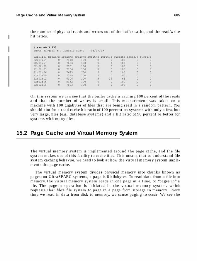
Page Cache and Virtual Memory System 605
the number of physical reads and writes out of the buffer cache, and the read/writehit ratios.
On this system we can see that the buffer cache is caching 100 percent of the readsand that the number of writes is small. This measurement was taken on amachine with 100 gigabytes of files that are being read in a random pattern. Youshould aim for a read cache hit ratio of 100 percent on systems with only a few, butvery large, files (e.g., database systems) and a hit ratio of 90 percent or better forsystems with many files.
15.2 Page Cache and Virtual Memory System
The virtual memory system is implemented around the page cache, and the filesystem makes use of this facility to cache files. This means that to understand filesystem caching behavior, we need to look at how the virtual memory system imple-ments the page cache.
The virtual memory system divides physical memory into chunks known aspages; on UltraSPARC systems, a page is 8 kilobytes. To read data from a file intomemory, the virtual memory system reads in one page at a time, or “pages in” afile. The page-in operation is initiated in the virtual memory system, whichrequests that file’s file system to page in a page from storage to memory. Everytime we read in data from disk to memory, we cause paging to occur. We see the
# sar -b 3 333SunOS zangief 5.7 Generic sun4u 06/27/99
22:01:51 bread/s lread/s %rcache bwrit/s lwrit/s %wcache pread/s pwrit/s22:01:54 0 7118 100 0 0 100 0 022:01:57 0 7863 100 0 0 100 0 022:02:00 0 7931 100 0 0 100 0 022:02:03 0 7736 100 0 0 100 0 022:02:06 0 7643 100 0 0 100 0 022:02:09 0 7165 100 0 0 100 0 022:02:12 0 6306 100 8 25 68 0 022:02:15 0 8152 100 0 0 100 0 022:02:18 0 7893 100 0 0 100 0 0

606 Solaris File System Cache
tally when we look at the virtual memory statistics. For example, reading a filewill be reflected in vmstat as page-ins.
In our example, we can see that by starting a program that does random reads of afile, we cause a number of page-ins to occur, as indicated by the numbers in the picolumn of vmstat . Note that the free memory column in vmstat has dropped to alow value; in fact, the amount of free memory is almost zero. This situation occursbecause the file system consumes a page of physical memory every time it pages ina page-sized chunk of a file. Have you ever noticed that when you boot yourmachine there is a lot of free memory, and as the machine is used, memory contin-ues to fall to zero, then just hangs there? Here is why: the file system is using allavailable memory to cache the reads and writes to each file—and it’s completelynormal.
Memory is put back on the free list by the page scanner, which looks for mem-ory pages that have not been used recently. The page scanner runs when memoryfalls to a system parameter known as lotsfree . In this example, we can see fromthe scan rate (sr) column that the page scanner is scanning about 50 pages per sec-ond to replace the memory used by the file system.
There is no parameter equivalent to bufhwm for the page cache. The page cachesimply grows to consume all available memory, which includes all process memorythat has not been used recently by applications. The rate at which the systempages and the rate at which the page scanner runs are proportional to the rate atwhich the file system is reading or writing pages to disk. On large systems, youshould expect to see large paging values—it’s completely normal.
Consider a system that is reading 10 megabytes per second through the file sys-tem; this translates to 1,280 page-ins per second and means that the page scannermust scan enough memory to be able to free 1,280 pages per second. The pagescanner must actually scan faster than 1,280 pages per second, since not all mem-ory the page scanner comes across will be eligible for freeing (the page scanneronly frees memory that hasn’t been used recently). If the page scanner finds onlyone out of three pages eligible for freeing, then it would need to run at 3,840 pagesper second. Don’t worry about high scan rates; if you are using the file systemheavily, then they are normal. There are many myths about high scan rates mean-
# ./rreadtest testfile&
# vmstat procs memory page disk faults cpu r b w swap free re mf pi po fr de sr s0 -- -- -- in sy cs us sy id 0 0 0 50436 2064 5 0 81 0 0 0 0 15 0 0 0 168 361 69 1 25 74 0 0 0 50508 1336 14 0 222 0 0 0 0 35 0 0 0 210 902 130 2 51 47 0 0 0 50508 648 10 0 177 0 0 0 0 27 0 0 0 168 850 121 1 60 39 0 0 0 50508 584 29 57 88 109 0 0 6 14 0 0 0 108 5284 120 7 72 20 0 0 0 50508 484 0 50 249 96 0 0 18 33 0 0 0 199 542 124 0 50 50 0 0 0 50508 492 0 41 260 70 0 0 56 34 0 0 0 209 649 128 1 49 50 0 0 0 50508 472 0 58 253 116 0 0 45 33 0 0 0 198 566 122 1 46 53

Page Cache and Virtual Memory System 607
ing you have a shortage of memory; perhaps this explanation reassures you thathigh scan rates can be normal in many circumstances.
Having all of free memory used for a cache makes it harder to observe howmuch memory is really free and also makes it hard to see how much memory isbeing used as a file system cache. The MemTool package (see “File System Cach-ing Memory” on page 236) can display the amount of memory that is being used asa file system cache.
15.2.1 File System Paging Optimizations
Some file systems try to reduce the amount of memory pressure by doing twothings: invoking free-behind with sequential access and freeing pages when freememory falls to lotsfree . Free-behind is invoked on UFS when a file is accessedsequentially so that the cache is not polluted when we do a sequential scanthrough a large file. This means that when we create or sequentially read a file, wedon’t see high scan rates.
Also, some checks in some file systems limit the file system’s use of the pagecache when memory falls to lotsfree . An additional parameter,pages_before_pager , used by the UFS, reflects the amount of memory above thepoint where the page scanner starts; by default pages_before_pager is 200pages. This means that when memory falls to 1.6 megabytes (on UltraSPARC)above lotsfree , the file system throttles back the use of the page cache. To bespecific, when memory falls to lotsfree + pages_before_pager , the followinghappens:
• Solaris file systems free all pages after they are written• UFS and NFS enable free-behind on sequential access• NFS disables read-ahead• NFS writes synchronously, rather than asynchronously• VxFS enables free-behind (some versions only)
# prtmem
Total memory: 242 MegabytesKernel Memory: 35 MegabytesApplication memory: 139 MegabytesExecutable memory: 50 MegabytesBuffercache memory: 7 MegabytesFree memory:

608 Solaris File System Cache
15.3 Is All That Paging Bad for My System?
Although we stated earlier that it may be normal to have high paging and scanrates, it is likely that the page scanner will be putting too much pressure on yourapplication’s private process memory. If we scan at a rate of several hundred pagesor more per second, then the amount of time that the page scanner takes to checkwhether a page has been accessed falls to a few seconds. This means that anypages that have not been used in the last few seconds will be taken by the pagescanner when you are using the file system. This behavior can negatively affectapplication performance and is the reason why priority paging was introduced.
If your system seems slow while file system I/O is going on, it’s because yourapplications are being paged in and out as a direct result of the file system activity.
For example, consider an OLTP application that makes heavy use of the file sys-tem. The database is generating file system I/O, making the page scanner activelysteal pages from the system. The user of the OLTP application has paused for 15seconds to read the contents of a screen from the last transaction. During thistime, the page scanner has found that those pages associated with the user appli-cation have not been referenced and makes them available for stealing. The pagesare stolen, and when the user types the next keystroke, the user is forced to waituntil the application is paged back in—usually several seconds. Our user is forcedto wait for an application to page in from the swap device, even though the applica-tion is running on a system with sufficient memory to keep all of the application inphysical memory!
The priority paging algorithm effectively places a boundary around the filecache so that file system I/O does not cause unnecessary paging of applications.The algorithm prioritizes the different types of pages in the page cache, in order ofimportance:
• Highest — Pages associated with executables and shared libraries, includingapplication process memory (anonymous memory)
• Lowest — Regular file cache pages
When the dynamic page cache grows to the point where free memory falls toalmost zero, the page scanner wakes up and begins scanning, but as long as thesystem has sufficient memory, the scanner only steals pages associated with regu-lar files. The file system effectively pages against itself rather than against every-thing else on the system.
Should there be a real memory shortage where there is insufficient memory forthe applications and kernel, the scanner is again allowed to steal pages from theapplications. By default, priority paging is disabled. It is likely to be enabled bydefault in a Solaris release subsequent to Solaris 7. To use priority paging, you will
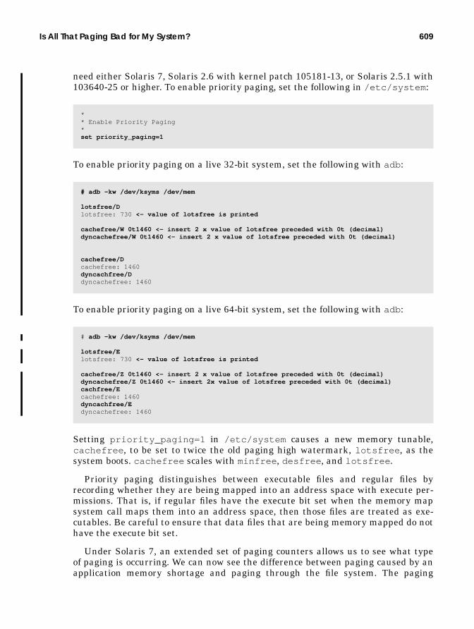
Is All That Paging Bad for My System? 609
need either Solaris 7, Solaris 2.6 with kernel patch 105181-13, or Solaris 2.5.1 with103640-25 or higher. To enable priority paging, set the following in /etc/system :
To enable priority paging on a live 32-bit system, set the following with adb :
To enable priority paging on a live 64-bit system, set the following with adb :
Setting priority_paging=1 in /etc/system causes a new memory tunable,cachefree , to be set to twice the old paging high watermark, lotsfree , as thesystem boots. cachefree scales with minfree , desfree , and lotsfree .
Priority paging distinguishes between executable files and regular files byrecording whether they are being mapped into an address space with execute per-missions. That is, if regular files have the execute bit set when the memory mapsystem call maps them into an address space, then those files are treated as exe-cutables. Be careful to ensure that data files that are being memory mapped do nothave the execute bit set.
Under Solaris 7, an extended set of paging counters allows us to see what typeof paging is occurring. We can now see the difference between paging caused by anapplication memory shortage and paging through the file system. The paging
** Enable Priority Paging*set priority_paging=1
# adb -kw /dev/ksyms /dev/mem
lotsfree/Dlotsfree: 730 <- value of lotsfree is printed
cachefree/W 0t1460 <- insert 2 x value of lotsfree preceded with 0t (decimal)dyncachefree/W 0t1460 <- insert 2 x value of lotsfree preceded with 0t (decimal)
cachefree/Dcachefree: 1460dyncachfree/Ddyncachefree: 1460
# adb -kw /dev/ksyms /dev/mem
lotsfree/Elotsfree: 730 <- value of lotsfree is printed
cachefree/Z 0t1460 <- insert 2 x value of lotsfree preceded with 0t (decimal)dyncachefree/Z 0t1460 <- insert 2x value of lotsfree preceded with 0t (decimal)cachfree/Ecachefree: 1460dyncachfree/Edyncachefree: 1460
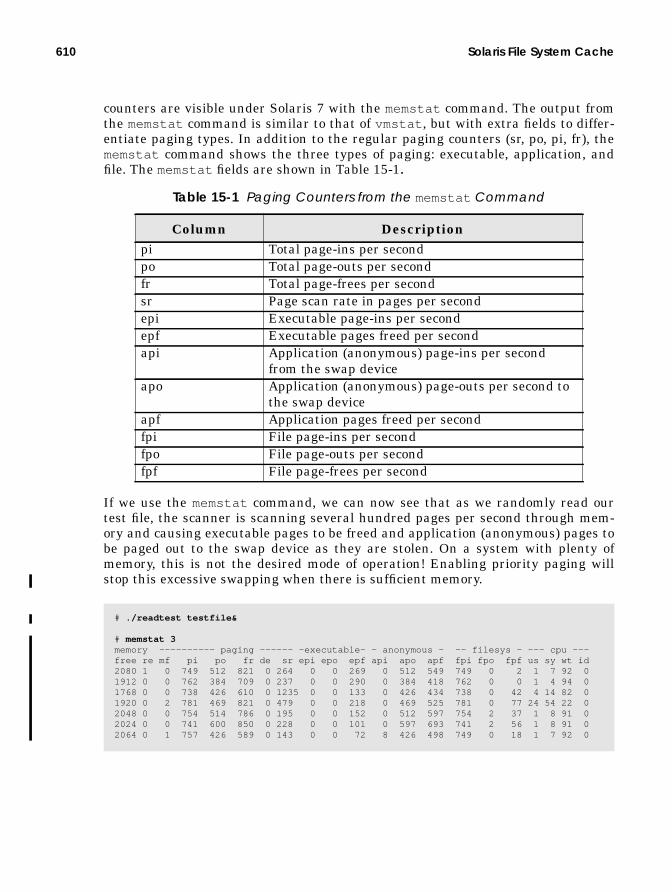
610 Solaris File System Cache
counters are visible under Solaris 7 with the memstat command. The output fromthe memstat command is similar to that of vmstat , but with extra fields to differ-entiate paging types. In addition to the regular paging counters (sr, po, pi, fr), thememstat command shows the three types of paging: executable, application, andfile. The memstat fields are shown in Table 15-1.
If we use the memstat command, we can now see that as we randomly read ourtest file, the scanner is scanning several hundred pages per second through mem-ory and causing executable pages to be freed and application (anonymous) pages tobe paged out to the swap device as they are stolen. On a system with plenty ofmemory, this is not the desired mode of operation! Enabling priority paging willstop this excessive swapping when there is sufficient memory.
Table 15-1 Paging Counters from the memstat Command
Column Descriptionpi Total page-ins per secondpo Total page-outs per secondfr Total page-frees per secondsr Page scan rate in pages per secondepi Executable page-ins per secondepf Executable pages freed per secondapi Application (anonymous) page-ins per second
from the swap deviceapo Application (anonymous) page-outs per second to
the swap deviceapf Application pages freed per secondfpi File page-ins per secondfpo File page-outs per secondfpf File page-frees per second
# ./readtest testfile&
# memstat 3memory ---------- paging ------ -executable- - anonymous - -- filesys - --- cpu ---free re mf pi po fr de sr epi epo epf api apo apf fpi fpo fpf us sy wt id2080 1 0 749 512 821 0 264 0 0 269 0 512 549 749 0 2 1 7 92 01912 0 0 762 384 709 0 237 0 0 290 0 384 418 762 0 0 1 4 94 01768 0 0 738 426 610 0 1235 0 0 133 0 426 434 738 0 42 4 14 82 01920 0 2 781 469 821 0 479 0 0 218 0 469 525 781 0 77 24 54 22 02048 0 0 754 514 786 0 195 0 0 152 0 512 597 754 2 37 1 8 91 02024 0 0 741 600 850 0 228 0 0 101 0 597 693 741 2 56 1 8 91 02064 0 1 757 426 589 0 143 0 0 72 8 426 498 749 0 18 1 7 92 0

Paging Parameters That Affect File System Performance 611
With priority paging enabled, we can see the different behavior of the virtualmemory system.
With the same test program, random reads on the file system again cause the sys-tem to page, and the scanner is actively involved in managing the pages, but nowthe scanner is freeing only file pages. The zeros in the executable and anonymousmemory columns clearly show that the scanner is choosing file pages first. Theactivity shown in the fpi and fpf columns means that file pages are being read inand an equal number are freed by the page scanner to make room for more reads.
15.4 Paging Parameters That Affect File System Performance
When priority paging is enabled, you will notice that the file system scan rate ishigher. Because the page scanner must skip over process private memory and exe-cutables, it needs to scan more pages before it finds file pages that it can steal.High scan rates are always found on systems that make heavy use of the file sys-tem and so should not be used as a factor for determining memory shortage. If youhave Solaris 7, then the memstat command will reveal if you are paging to theswap device; such paging suggests that you are short of memory.
If you have high file system activity, then you will find that the scanner parame-ters are insufficient and will limit file system performance. To compensate, youmust set the scanner parameters fastscan and maxpgio to allow the scanner toscan at a high enough rate to keep up with the file system.
By default, the scanner is limited by the fastscan parameter, which reflectsthe number of pages per second that the scanner can scan. It defaults to scanone-fourth of memory every second and is limited to 64 megabytes per second. Thescanner runs at half of fastscan when memory is at lotsfree , which limits it to32 megabytes per second. If only one in three physical memory pages is a file page,then the scanner will only be able to put 32 / 3 = 11 megabytes per second of mem-ory on the free list, limiting file system throughput. So, to allow the page scanner
# ./readtest testfile&
# memstat 3memory ---------- paging ----------- - executable - - anonymous - -- filesys -- --- cpu --- free re mf pi po fr de sr epi epo epf api apo apf fpi fpo fpf us sy wt id 3616 6 0 760 0 752 0 673 0 0 0 0 0 0 760 0 752 2 3 95 0 3328 2 198 816 0 925 0 1265 0 0 0 0 0 0 816 0 925 2 10 88 0 3656 4 195 765 0 792 0 263 0 0 0 2 0 0 762 0 792 7 11 83 0 3712 4 0 757 0 792 0 186 0 0 0 0 0 0 757 0 792 1 9 91 0 3704 3 0 770 0 789 0 203 0 0 0 0 0 0 770 0 789 0 5 95 0 3704 4 0 757 0 805 0 205 0 0 0 0 0 0 757 0 805 2 6 92 0 3704 4 0 778 0 805 0 266 0 0 0 0 0 0 778 0 805 1 6 93 0

612 Solaris File System Cache
to scan fast enough, increase fastscan to, say, one-fourth of memory, with anupper limit of 1 gigabyte per second. That upper limit translates to 131072 for thefastscan parameter.
The maxpgio parameter is the maximum number of pages the page scanner canpush. maxpgio can also limit the number of file system pages that are pushed,thus limiting the write performance of the file system. If your system has suffi-cient memory, then we recommend setting maxpgio to something large, say, 1024.On the E10000 systems, this is the default for maxpgio . For example, on a4-gigabyte machine, one-fourth of memory is 1 gigabyte, so we would setfastscan to 131072. Our parameters, set in /etc/system , for this machine areshown below.
In summary, we have seen the a strong relationship between the VM system andfile system behavior. The parameters that control the paging system have the mostinfluence on file system performance, since they govern the way pages are madeavailable to the file system. Figure 15.3 depicts the paging parameters that affectfile systems and the memory parameters that control paging as the amount of freememory falls to the point where it hits these parameters.
** Parameters to allow better file system throughput*set fastscan=131072set handspreadpages=131072set maxpgio=1024

Paging Parameters That Affect File System Performance 613
Figure 15.3 VM Parameters That Affect File Systems
0
throttlefree
minfree
desfree
lotsfree
lotsfree +
When free memory falls below thisthreshold, the file system starts freeingall writes and UFS read-ahead is dis-abled.
When free memory falls below lots-free , the scanner starts freeing anon-ymous (application heap) andexecutable pages in addition to file pag-es. This only happens when the scan-ner is not able to keep up with the rateof file system I/O.
If free memory falls to desfree , thennfs version 3 stops writing asynchro-nously, kernel async I/O stalls, and idleprocesses are swapped out.
When free memory falls below cache-free , pages that are not mapped exe-cutable are freed. The scanner startsscanning at a rate governed by slow-scan .
Noncritical memory requests areblocked.
All memory requests are blocked.
When free memory falls below cache-free , file pages (which are notmapped executable) are freed. Thescanner starts scanning at a rate ofslowscan .
cachefree
The earth stops rotating if freemem==0
(Parameters are measured inunits of pages.)
pages_before_pager
slowscan
fastscan
The rate at whichpages are madeavailable to thefile system var-ies with the scanrate and iscapped byfastscan or95% of 1 CPU.
pageout_reserve(60)

614 Solaris File System Cache
15.5 Bypassing the Page Cache with Direct I/O
In some cases we may want to do completely unbuffered I/O to a file. A direct I/Ofacility in most file systems allows a direct file read or write to completely bypassthe file system page cache.
15.5.1 UFS Direct I/O
Support for direct I/O was added to UFS starting with Solaris 2.6. Direct I/Oallows reads and writes to files in a regular file system to bypass the page cacheand access the file at near raw disk performance. Direct I/O can be advantageouswhen you are accessing a file in a manner where caching is of no benefit. For exam-ple, if you are copying a very large file from one disk to another, then it is likelythat the file will not fit in memory and you will just cause the system to pageheavily. By using direct I/O, you can copy the file through the file system withoutreading through the page cache and eliminate the memory pressure caused by thefile system and the additional CPU cost of the layers of cache.
Direct I/O also eliminates the double copy that is performed when the read andwrite system calls are used. When we read a file through normal buffered I/O, thefile system (1) uses a DMA transfer from the disk controller into the kernel’saddress space and (2) copies the data into the buffer supplied by the user in theread system call. Direct I/O eliminates the second step by arranging for the DMAtransfer to occur directly into the user’s address space.
Direct I/O will only bypass the buffer cache if all of the following are true:
• The file is not memory mapped.• The file is not on a logging file system.
• The file does not have holes.• The read/write is sector aligned (512 byte).You enable direct I/O by mounting an entire file system with the force-
directio mount option, as shown below.
You can also enable direct I/O with the directio system call, on a per-file basis.Note that the change is file based, and every reader and writer of the file will beforced to use directio once it’s enabled.
# mount -o forcedirectio /dev/dsk/c0t0d0s6 /u1
int directio(int fildes, DIRECTIO_ON | DIRECTIO_OFF);
Header File <sys/fcntl.h>

Directory Name Cache 615
Direct I/O can provide extremely fast transfers when moving data with big blocksizes (>64 kilobytes), but it can be a significant performance limitation for smallersizes. If an application reads and writes in small sizes, then its performance maysuffer since there is no read-ahead or write clustering and no caching.
Databases are a good candidate for direct I/O since they cache their own blocksin a shared global buffer and can arrange to do their own clustering of reads andwrites into larger operations.
A set of direct I/O statistics is provided with the ufs implementation by meansof the kstat interface. The structure exported by ufs_directio_kstats isshown below. Note that this structure may change, and performance tools shouldnot rely on the format of the direct I/O statistics.
You can inspect the direct I/O statistics with an engineering utility from our web-site at http://www.solarisinternals.com.
15.5.2 Direct I/O with Veritas VxFS
VxFS also provides a direct I/O implementation, which by default switches onwhenever the read or write size is 256 kilobytes or greater. This VxFS feature isknown as discovered direct I/O.
15.6 Directory Name Cache
The directory name cache caches path names for vnodes , so that when we open afile that has been opened recently, we don’t need to rescan the directory to find thefile name again. Each time we find the path name for a vnode , we store it in thedirectory name cache. (See “The Directory Name Lookup Cache (DNLC)” on
struct ufs_directio_kstats { uint_t logical_reads; /* Number of fs read operations */ uint_t phys_reads; /* Number of physical reads */ uint_t hole_reads; /* Number of reads from holes */ uint_t nread; /* Physical bytes read */ uint_t logical_writes; /* Number of fs write operations */ uint_t phys_writes; /* Number of physical writes */ uint_t nwritten; /* Physical bytes written */ uint_t nflushes; /* Number of times cache was cleared */} ufs_directio_kstats;
# directiostat 3 lreads lwrites preads pwrites Krd Kwr holdrds nflush 0 0 0 0 0 0 0 0 0 0 0 0 0 0 0 0 0 0 0 0 0 0 0 0

616 Solaris File System Cache
page 568 for further information on the DNLC operation.) The number of entriesin the DNLC is set by the system-tunable parameter, ncsize , which is set at boottime by the calculations shown in Table 15-2. The ncsize parameter is calculatedin proportion to the maxusers parameter, which is equal to the number of mega-bytes of memory installed in the system, capped by a maximum of 1024. The max-users parameter can also be overridden in /etc/system to a maximum of 2048.
The size of the DNLC rarely needs to be adjusted because the size scales with theamount of memory installed in the system. Earlier Solaris versions had a defaultmaximum of 17498 (34906 with maxusers set to 2048), and later Solaris versionshave a maximum of 69992 (139624 with maxusers set to 2048).
Use adb to determine the size of the DNLC.
The hit rate of the directory name cache shows the number of times a name waslooked up and found in the name cache. A high hit rate (>90%) shows that theDNLC is working well. A low hit rate does not necessarily mean that the DNLC isundersized; it simply means that we are not always finding the names we want inthe name cache. This situation can occur if we are creating a large number of files.
Table 15-2 DNLC Default Sizes
Solaris Version Default ncsize CalculationSolaris 2.4, 2.5, 2.5.1 ncsize = (17 * maxusers ) + 90Solaris 2.6, 2.7 ncsize = (68 * maxusers ) + 360
# adb -kphysmem b919ncsize/Dncsize:ncsize: 25520

Inode Caches 617
The reason is that a create operation checks to see if a file exists before it createsthe file, causing a large number of cache misses.
15.7 Inode Caches
Disk-based file systems attempt to keep a number of inodes in memory, even if thefile for that inode is not open or referenced. This is done for two reasons: to mini-mize disk inode reads by caching the inode in memory and to keep the inode’svnode in memory so that file pages remain in the page cache. The number ofinodes that the system will attempt to keep in memory is indirectly controlled by asystem parameter: ufs_ninode .
15.7.1 UFS Inode Cache Size
The UFS uses the ufs_ninode parameter to size the file system tables for theexpected number of inodes. To understand how the ufs_ninode parameter affectsthe number of inodes in memory, we need to look at how the UFS maintainsinodes. Inodes are created when a file is first referenced. They remain in memorymuch longer than when the file is last referenced because inodes can be in one of
# vmstat -s 0 swap ins 0 swap outs 0 pages swapped in 0 pages swapped out 405332 total address trans. faults taken 1015894 page ins 353 page outs 4156331 pages paged in 1579 pages paged out 3600535 total reclaims 3600510 reclaims from free list 0 micro (hat) faults 405332 minor (as) faults 645073 major faults 85298 copy-on-write faults 117161 zero fill page faults 0 pages examined by the clock daemon 0 revolutions of the clock hand 4492478 pages freed by the clock daemon 3205 forks 88 vforks 3203 execs 33830316 cpu context switches 58808541 device interrupts 928719 traps214191600 system calls 14408382 total name lookups (cache hits 90%) 263756 user cpu 462843 system cpu 14728521 idle cpu 2335699 wait cpu

618 Solaris File System Cache
two states: either the inode is referenced, or the inode is no longer referenced butis on an idle queue. Inodes are eventually destroyed when they are pushed off theend of the inode idle queue. Refer to “Freeing inodes—the Inode Idle List” onpage 598 for a description of how ufs inodes are maintained on the idle queue.
The number of inodes in memory is dynamic. Inodes will continue to be allo-cated as new files are referenced. There is no upper bound to the number of inodesopen at a time; if one million inodes are opened concurrently, then a little over onemillion inodes will be in memory at that point. A file is referenced when its refer-ence count is nonzero, which means either the file is open for a process or anothersubsystem such as the directory name lookup cache is referring to the file.
When inodes are no longer referenced (the file is closed and no other subsystemis referring to the file), the inode is placed on the idle queue and eventually freed.The size of the idle queue is controlled by the ufs_ninode parameter and is lim-ited to one-fourth of ufs_ninode . The maximum number of inodes in memory at agiven point is the number of active referenced inodes plus the size of the idle queue(typically, one-fourth of ufs_ninode ). Figure 15.4 illustrates the inode cache.
We can use the sar command and inode kernel memory statistics to determine thenumber of inodes currently in memory. sar shows us the number of inodes cur-rently in memory and the maximum reached. We can find similar information by
Open Files
Files in the Name Cache (DNLC) Inodes in the idle queue
inodes
(number <= ncsize) (number <= ufs_ninode/4)
Figure 15.4 In-Memory Inodes (Referred to as the “Inode Cache”)

Inode Caches 619
looking at the buf_inuse and buf_total parameters in the inode kernel mem-ory statistics.
The inode memory statistics show us how many inodes are allocated by thebuf_inuse field. We can also see from the ufs inode memory statistics that thesize of each inode is 440 bytes. We can use this value to calculate the amount ofkernel memory required for desired number of inodes when setting ufs_ninodeand the directory name cache size.
The ufs_ninode parameter controls the size of the hash table that is used tolook up inodes and indirectly sizes the inode idle queue (ufs_ninode / 4). Theinode hash table is ideally sized to match the total number of inodes expected to bein memory—a number that is influenced by the size of the directory name cache.By default, ufs_ninode is set to the size of the directory name cache, which pro-vides approximately the correct size for the inode hash table. In an ideal world, wecould set ufs_ninode to four-thirds the size of the DNLC, to take into account thesize of the idle queue, but practice has shown this unnecessary.
We typically set ufs_ninode indirectly by setting the directory name cache size(ncsize ) to the expected number of files accessed concurrently, but it is possible toset ufs_ninode separately in /etc/system .
# sar -v 3 3
SunOS devhome 5.7 Generic sun4u 08/01/99
11:38:09 proc-sz ov inod-sz ov file-sz ov lock-sz11:38:12 100/5930 0 37181/37181 0 603/603 0 0/011:38:15 100/5930 0 37181/37181 0 603/603 0 0/011:38:18 101/5930 0 37181/37181 0 607/607 0 0/0
# netstat -k ufs_inode_cacheufs_inode_cache:buf_size 440 align 8 chunk_size 440 slab_size 8192 alloc 1221573 alloc_fail 0free 1188468 depot_alloc 19957 depot_free 21230 depot_contention 18 global_alloc 48330global_free 7823 buf_constructed 3325 buf_avail 3678 buf_inuse 37182buf_total 40860 buf_max 40860 slab_create 2270 slab_destroy 0 memory_class 0hash_size 0 hash_lookup_depth 0 hash_rescale 0 full_magazines 219empty_magazines 332 magazine_size 15 alloc_from_cpu0 579706 free_to_cpu0 588106buf_avail_cpu0 15 alloc_from_cpu1 573580 free_to_cpu1 571309 buf_avail_cpu1 25
* Set number of inodes stored in UFS inode cache*set ufs_ninode = new_value

620 Solaris File System Cache
15.7.2 VxFS Inode Cache
The Veritas file system uses a similar parameter, vxfs_ninode , to control the sizeof the inode cache. It also attempts to keep one-fourth of the vxfs_ninode param-eter number of inodes on the inode idle queue.
* Set number of inodes stored in VxFS inode cache*set vxfs:vxfs_ninode = new_value
A
KERNEL TUNABLES,SWITCHES, AND LIMITS
In this appendix, we provide several tables showing the various kernel settableparameters. The variables listed here do not represent every kernel variable thatcan be altered. Almost any kernel variable that is visible to the kernel linker canbe altered with an entry in the /etc/system file or with a debugger like adb (1).Certainly, it was never intended that each and every kernel variable, along with itsmeaning and possible values, be documented as user settable. Most have neverbeen intended for public use, but rather exist for debugging or experimentation.Here we list what we consider the mainstream variables—those that have alwaysbeen intended to be user settable—and several that are not as well known but thathave proved to be useful for some installations.
A.1 Setting Kernel Parameters
You establish settable kernel tunable parameters by adding an entry to the/etc/system file, in the form of:
set parameter = value
or
set kernel_module:parameter = value
The second example applies to those kernel variables that are part of a loadablekernel module, where the module name is separated by a colon from the variable
621

622 Kernel Tunables, Switches, and Limits
name in the entry. The values in the /etc/system file are read at boot time, soany changes made to this file require a reboot to take effect.
These settable kernel variables are traditionally referred to as kernel tunableparameters. The settable kernel variables can be more accurately categorized intoone of three groups:
• Switches — Refers to a kernel parameter that simply turns on or off a par-ticular behavior or functional component, which, of course, affects systembehavior and performance. An example of a switch is the priority_pagingparameter, which is either on (value of 1) or off (value of 0).
• Limits — Refers to kernel variables that impose hard limits on a particularresource. The System V IPC tunables fall into the limit category. Several oth-ers do as well.
• Tunables — Refers to kernel variables that will alter performance or behav-ior. Think of these as a tuning knob that has a range of values (0 to N, whereN represents that maximum allowable value).
Kernel parameters can be further divided into those parameters that are set ontypical installations and impose minimal risk, and those that are less well knownand not well understood. Changing the value of any kernel parameter imposessome level of risk. However, many of the kernel limit parameters, such as those setfor System V IPC resources, are set on many installations and are generally wellunderstood. Others can alter system behavior and performance, and sometimes itis not easy (or even possible) to predict which direction performance will move in(better or worse) as a result of changing a particular value.
In the tables that follow, we list the various kernel settable parameters, indicat-ing their category (switch, limit, tunable) and whether or not we believe that theparameter is something that may impact system behavior in an unpredictable way,where such a warning is applicable. We also provide a reference to the page num-ber in the book where more information about the kernel variable can be found.
As a practice, you should never change a kernel settable parameter in aproduction system without first trying the value in a lab environment andthen testing extensively.
A.2 System V IPC - Shared Memory Parameters
Table A-1 describes shared memory parameters. For more information, refer to“System V Shared Memory” on page 433.

System V IPC - Shared Memory Parameters 623
Table A-2 lists System V IPC semaphores. For more information, refer to “SystemV Semaphores” on page 444.
Table A-3 describes message queues. For more information, refer to “System VMessage Queues” on page 451.
Table A-1 System V IPC - Shared Memory
Parameter Default Category Description / Notesshmmax 1048576 Limit System V IPC shared memory. Maximum
shared memory segment size, in bytes.shmmin 1 Limit System V IPC shared memory. Minimum
shared memory segment size, in bytes.shmmni 100 Limit System V IPC shared memory. Maximum
number of shared memory segments, sys-temwide.
shmseg 6 Limit System V IPC shared memory. Maximumnumber of shared segments, per process.
segspt_minfree 5% of availablememory
Limit Number of pages of physical memory notavailable for allocation as ISM shared seg-ments. Default value translates to allowingup to 95% of available memory get allocatedto ISM shared segments.
Table A-2 System V IPC - Semaphores
Parameter Default Category Description / Notessemmap 10 Limit Size of the semaphore map.semmni 10 Limit Maximum number of semaphore identifiers,
systemwide.semmns 60 Limit Maximum number of semaphores, system-
wide. Should be the product of semmni andsemmsl .
semmnu 30 Limit Maximum number of semaphore undo struc-tures, systemwide.
semmsl 25 Limit Maximum number of semaphores per sema-phore ID.
semopm 10 Limit Maximum number of semaphore operationsper semop() call.
semume 10 Limit Maximum per-process undo structures.semvmx 32767 Limit Maximum value of a semaphore.semaem 16384 Limit Maximum adjust-on-exit value.

624 Kernel Tunables, Switches, and Limits
A.3 Virtual Memory Parameters
Table A-4 lists parameters that relate to the virtual memory system and pagingactivity. Such activity is closely tied to file system I/O because of the buffer cach-ing done by file systems such as UFS and VxFS.
You can read more about the memory paging parameters in “Summary of PageScanner Parameters” on page 186, “Solaris File System Cache” on page 601, “PageCache and Virtual Memory System” on page 605, and “In summary, we have seenthe a strong relationship between the VM system and file system behavior. Theparameters that control the paging system have the most influence on file systemperformance, since they govern the way pages are made available to the file sys-tem. Figure 15.3 depicts the paging parameters that affect file systems and thememory parameters that control paging as the amount of free memory falls to thepoint where it hits these parameters.” on page 612.
Table A-3 System V IPC - Message Queues
Parameter Default Category Description/Notesmsgmap 100 Limit Maximum size of resource map for messages.msgmax 2048 Limit Maximum size, in bytes, of a message.msgmnb 4096 Limit Maximum number of bytes on a message
queue.msgmni 50 Limit Maximum number message queue identifi-
ers, systemwide.msgssz 8 Limit Message segment size.msgtql 40 Limit Maximum number of message headers, sys-
temwide.msgseg 1024 Limit Maximum number of message segments.
Table A-4 Virtual Memory
Parameter Default Category Description/Notesfastscan 1/4th of physi-
cal memory, or64 MB, which-ever is larger.
Tunable The maximum number of pages per secondthe page scanner will scan.
slowscan 100 Tunable Initial page scan rate, in pages per second.lotsfree 1/64th of physi-
cal memory, or512 KB, which-ever is larger.
Tunable Desired size of the memory free list (numberof free pages). When the free list drops belowlotsfree , the page scanner runs.

Virtual Memory Parameters 625
desfree lotsfree / 2. Tunable Free memory desperation threshold. Whenfreemem drops below desfree , the pagescan rate increases and the system will alterits default behavior for specific events. des-free must be less than lotsfree .
minfree desfree / 2. Tunable Minimum acceptable amount of free mem-ory. minfree must be less than desfree .
throttlefree minfree Tunable Memory threshold at which the kernel willblock memory allocation requests. Must beless than minfree .
pageout_reserve throttle-free / 2
Tunable Memory pages reserved for pageout andmemory scheduler threads. When freememdrops below pageout_reserve , memoryallocations are denied for anything otherthan pageout and sched.
priority_paging 0 Switch Enables priority paging when set to 1. Prior-ity paging relieves memory pressure on exe-cutable pages due to cached file systemactivity. Priority paging is available forSolaris 2.6 with kernel jumbo patch105181-10 or greater. It is in Solaris 7.
cachefree * Tunable The memory page threshold that triggers thepriority paging behavior, where file systemcache pages are marked for pageout only aslong as freemem is below cachefree butabove lotsfree . cachefree must begreater than lotsfree .
* If priority_paging is 0, then cache-free = lotsfree . If priority_paging is1 (enabled), then cachefree = (lotsfree *2)
pages_pp_maximum * Limit Number of pages the system requires remainunlocked.
* 200, or tune_t_minarmem , or 10% ofavailable memory, whichever is greater.
tune_t_minarmem 25 Limit Minimum number of memory pages reservedfor the kernel. A safeguard to ensure that aminimum amount of nonswappable memoryis available to the kernel.
min_percent_cpu 4 Tunable Minimum percentage of CPU time pageoutcan consume.
Table A-4 Virtual Memory
Parameter Default Category Description/Notes

626 Kernel Tunables, Switches, and Limits
A.4 File System Parameters
The file system and page flushing parameters in Table A-5 provide for tuning filesystem performance and manage the flushing of dirty pages from memory to disk.
You can read more about the fsflush and associated parameters in “Bypassingthe Page Cache with Direct I/O” on page 614. “Directory Name Cache” on page 615and “Inode Caches” on page 617 have more information on the file system parame-ters directory and inode caches.
handspreadpages fastscan Tunable Number of pages between the first and sec-ond hand of the page scanner.
pages_before_pager 200 Tunable Used in conjunction with lotsfree to estab-lish the point at which the kernel will freefile system pages after an I/O. If availablememory is less than lotsfree +pages_before_pager , then the kernel willfree pages after an I/O (rather than keepthem in the page cache for reuse).
maxpgio 40 Tunable Maximum number of pageout operations persecond the kernel will schedule. Set to 100times the number of disks with swap files orswap partitions.
Table A-5 File System and Page Flushing Parameters
Parameter Default Category Description/Notestune_t_flushr 5 Tunable fsflush interval; the fsflush daemon runs
every tune_t_flushr seconds.autoup 30 Tunable Age in seconds of dirty pages. Used in con-
junction with tune_t_fsflushr ; modifiedpages that are older than autoup are writ-ten to disk.
dopageflush 1 Switch When set, enables dirty page flushing byfsflush . Can be set to zero to disable pageflushing.
doiflush 1 Switch Flag to control flushing of inode cache dur-ing fsflush syncs. Set to 0 to disable inodecache flushing.
Table A-4 Virtual Memory
Parameter Default Category Description/Notes

File System Parameters 627
ncsize * Limit Size of the directory name lookup cache(DNLC); a kernel cache that caches pathnames for vnodes for UFS and NFS files.
* ncsize defaults to (17 * maxusers ) + 90 on2.5.1, and (68 * maxusers ) + 360 on Solaris2.6 and 7.
bufhwm 2% of physicalmemory
Limit Maximum amount of memory (in Kbytes)allocated to the I/O buffer cache, whichcaches file system inodes, superblocks, indi-rect blocks, and directories.
ndquot ((maxusers *40) / 4) +max_nprocs
Limit Number of UFS quota structures to allocate.Applies only if quotas are enabled for UFS.
maxphys 126976 (sun4mand sun4d),131072 (sun4u),57344 (x86)
Limit Maximum physical I/O size, in bytes. Forsome devices, the maximum physical I/O sizeis set dynamically when the driver loads.
ufs_ninode ncsize Limit Number of inodes to cache in memory.ufs:ufs_WRITES 1 Switch Enables UFS per-file write throttle. See
below.ufs:ufs_LW 256 Kbytes Tunable UFS write throttle low watermark. See
below.ufs:ufs_HW 384 Kbytes Tunable UFS write throttle high watermark. If the
number of outstanding bytes to be written toa file exceeds ufs_HW, then writes aredeferred until ufs_LW or less is pending.
nrnode ncsize Limit Maximum number of rnodes allocated.rnodes apply to NFS files, and are the NFSequivalent of a UFS inode.
tmpfs_maxkmem Set dynami-cally whentmpfs is firstused.
Limit Maximum amount of kernel memory fortmpfs data structures. The value is set thefirst time tmpfs is used, to a range some-where between the memory page size of theplatform, to 25% of the amount of availablekernel memory.
tmpfs_minfree 256 pages Limit Minimum amount of swap space tmpfs willleave for non-tmpfs use (i.e., the rest of thesystem).
Table A-5 File System and Page Flushing Parameters
Parameter Default Category Description/Notes

628 Kernel Tunables, Switches, and Limits
Table A-6 lists parameters related to swapfs —the pseudofile that is a key com-ponent in the management of kernel anonymous memory pages. These parame-ters are generally not changed from their defaults.
A.5 Miscelaneous Parameters
Table A-7 lists miscellaneous kernel parameters. You can read more about many ofthe tunable parameters in “Kernel Bootstrap and Initialization” on page 107.
Table A-6 Swapfs Parameters
Parameter Default Category Description/Notesswapfs_reserve 4 MB or 1/16th
of memory,whichever issmaller
Limit The amount of swap reserved for system pro-cesses. Those processes owned by root (UID0).
swapfs_minfree 2 MB or 1/8 ofphysical mem-ory, whicheveris larger.
Limit Amount of memory the kernel keeps avail-able for the rest of the systems (all pro-cesses).
Table A-7 Miscellaneous Parameters
Parameter Default Category Description/Notesmaxusers MB of RAM Limit Generic tunable for sizing various kernel
resources.ngroups_max 16 Limit Maximum number of supplementary groups
a user can belong to.npty 48 Limit Number of pseudodevices, /dev/pts
slave devices, and /dev/pty controllerdevices.
pt_cnt 48 Limit Number of pseudodevices, /dev/pts slavedevices, and /dev/ptm master devices.
rstchown 1 Switch Enables POSIX_CHOWN_RESTRICTED behav-ior. Only a root process can change file own-ership. A process must be a current memberof the group to which it wishes to change afiles group, unless it is root.
rlim_fd_cur 64 Limit Maximum per-process open files.rlim_fd_max 1024 Limit Per process open files hard limit.
rlim_fd_cur can never be larger thanrlim_fd_max .

Miscelaneous Parameters 629
physmem number ofpages of RAM
Limit Can be set to reduce the effective amount ofusable physical memory. Values are in pages.
kobj_map_space_len 1 MB Limit Amount of kernel memory allocated to storesymbol table information. In Solaris 2.6, itdefines to total space for the kernel symboltable. In Solaris 7, space is dynamically allo-cated as needed, in units ofkobj_map_space_len .
kmem_flags 0 Switch Solaris 2.6 and later. Enable some level ofdebug of kernel memory allocation. Values:0x1 – AUDIT: maintain an activity audit log.0x2 – TEST: Allocator tests memory prior toallocation.0x3 – REDZONE: Allocator adds extra mem-ory to the end of an allocated buffer, andtests to determine if the extra memory waswritten into when the buffer is freed.0x4 – CONTENTS: Logs up to 256 bytes ofbuffer contents when buffer is freed.Requires AUDIT also be set.
kmem_debug_enable 0 Switch Kernel memory allocator debug flag. Allowskma debug information for any or all kmemcaches. Value of −1 in all caches. Solaris 2.6and 7 only. Removed in Solaris 7, 3/99.
moddebug 0 Switch Turn on kernel module debugging messages.The many possible values for moddebug canbe found in /usr/include/sys/modctl.h .Some useful values are:0x80000000 – print loading/unloading mes-sages.0x40000000 – print detailed error messages.
timer_max 32 Limit Number of POSIX timers (timer_create (2)system call) available.
consistent_coloring
0 Switch sun4u (UltraSPARC) only. Establishes thepage placement policy for physical pages andL2 cache blocks. Possible values are:0 – page coloring1 – virtual address = physical address2 – bin-hopping
Table A-7 Miscellaneous Parameters
Parameter Default Category Description/Notes

630 Kernel Tunables, Switches, and Limits
A.6 Process and Dispatcher (Scheduler) Parameters
The parameters listed in Table A-8 relate to the process and scheduler subsystemin Solaris. For more information, refer to “The Kernel Process Table” on page 290".
A.7 STREAMS Parameters
Table A-9 lists tunable parameters available for the kernel STREAMS subsystem.STREAMS are not covered in this version of the book.
Table A-8 Process and Dispatcher (Scheduler) Parameters
Parameter Default Category Description/Notesreserved_procs 5 Limit The number of process table slots reserved
for system processes.maxpid 30,000 Limit Maximum value for a PID, and the maxi-
mum number of processes that can exist onthe system at any one time.
max_nprocs (10 + 16 * max-users )
Limit Maximum number of process that can existon the system. Will be set to maxpid if it isset to a value greater than maxpid .
maxuprc max_nprocs −reserved_procs
Limit Maximum number of processes a non-rootuser can create.
noexec_user_stack 0 Switch If set to 1, stack pages are mapped noexec ,providing protection against buffer overflowattacks. 64-bit Solaris 7 maps stack pagesno-exec by default.
rechoose_interval 3 Tunable Clock tick count for thread-to-processoraffinity scheduling. The dispatcher attemptsto place a thread on the same processor itlast ran on, for optimal hardware cache hits.After rechoose_interval ticks, the nextavailable processor is chosen.
hires_tick 0 Tunable Default of 0 has the system generate 100clock interrupts per second (10 ms interval).Setting this value to 1 results in a 1 msinterval (1000 clock interrupts per second).

STREAMS Parameters 631
Table A-9 STREAMS Parameters
Parameter Default Category Description/Notesnstrpush 9 Limit Number of modules that can be pushed onto
a STREAM.strmsgsz 65536 Limit Maximum size (in bytes) of a STREAMS
data message.strctlsz 1024 Limit Maximum size (in bytes) of a STREAMS con-
trol message.sadcnt 16 Limit Number of STREAMS administrative driver
(sad ) devices.nautopush 32 Limit Number of sad autopush structures.

632 Kernel Tunables, Switches, and Limits

B
KERNEL VIRTUALADDRESS MAPS
In this appendix, we illustrate the allocation- and location-specific information forthe segments that constitute the Solaris 7 kernel address space.
The kernel address space is represented by the address space pointed to by thesystem object, kas . The segment drivers manage the manipulation of the seg-ments within the kernel address space. Figure B.1 illustrates the architecture.
Figure B.1 Kernel Address Space and Segments
struct seg
struct seg
struct segHardwareTranslation Information
kas struct as
a_size
a_nsegs
a_segs
a_flags
a_hat
a_tail
633
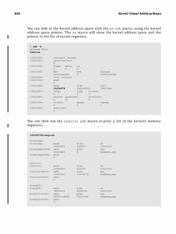
634 Kernel Virtual Address Maps
You can look at the kernel address space with the as adb macro, using the kerneladdress space pointer. The as macro will show the kernel address space and thepointer to the list of kernel segments.
You can then use the seglist adb macro to print a list of the kernel’s memorysegments.
# adb -kphysmem b91akas$<as
10423320: contents (mutex)10423320: owner/waiters 010423328: flags vbits cv 0 0 010423330: hat hrm seglast 300000ebf88 0 300002a9f8810423350: lock (rwlock)10423350: wwwh 010423368: segs size tail
10434678 2052c0000 104230e010423380: nsegs lrep hilevel 6 0 010423386: unused updatedir objectdir 0 01 010423390: sizedir wpage nwpage 0 0 010423340: userlimit 0
10434678$<seglist
ktextseg:ktextseg: base size as 10000000 4a0000 10423320ktextseg+0x18: next prev ops 1041fd60 0 segkmem_opsktextseg+0x30: data 0
kvalloc:kvalloc: base size as 104a0000 e20000 10423320kvalloc+0x18: next prev ops 104233a0 10434678 segkmem_opskvalloc+0x30: data 0
kvseg32:kvseg32: base size as 78000000 4000000 10423320kvseg32+0x18: next prev ops 300002a9f88 1041fd60 segkmem_opskvseg32+0x30: data 0
635
The next figures illustrate Solaris 7 address space, as follows:
• Figure B.2 Solaris 7 sun4u 64-Bit Kernel Address Space• Figure B.3 Solaris 7 sun4u 32-Bit Kernel Address Space• Figure B.4 Solaris 7 sun4d 32-Bit Kernel Address Space• Figure B.5 Solaris 7 sun4m 32-Bit Kernel Address Space• Figure B.6 Solaris 7 x86 32-Bit Kernel Address Space

636 Kernel Virtual Address Maps
0xFFFFFFFF.FFFFFFFF
0x0
Open Boot PromPage Tables
64-Bit Kernel Heapsegkmem
File System Cache
Pageable Kernel Mem.segkp
Open Boot Prom
Kernel Debugger
32-Bit Kernel Heapsegkmem32
Panic Message Buffer
Large TSB
sun4u HAT StructuresSmall TSB & Map Blks
Kernel Data Segment
Kernel Text Segment
Trap Table0x00000000.10000000
0x00000000.10400000
0x00000000.10400000
0x00000000.78000000
0x00000000.78002000
0x00000000.7c000000
0x00000000.EDD00000
0x00000000.F0000000
0x00000000.FFFFFFFF
0x000002A1.00000000
0x000002A7.50000000
0x00000300.00000000
0x00000302.00000000
0xFFFFFFFC.00000000
(8 Gbytes)
(256 Mbytes)
(512 Mbytes)
(4-Mbyte Pages)
(4 Mbytes)
(1 x 4-Mbyte Page)
(4 Mbytes)
(1 x 4-Mbyte Page)
Invalid
segmap
Figure B.2 Solaris 7sun4u 64-Bit Kernel
Address Space

637
0x0
Kernel Heapsegkmem
File System Cachesegmap
Pageable Kernel Mem.segkp
Open Boot Prom
Kernel Debugger
Large TSB
sun4u HAT StructuresSmall TSB & Map Blks
Kernel Data Segment
Kernel Text Segment
Trap Table0x10000000
0x10400000
0x10800000
0xEDD00000
0xF0000000
0xFFFFFFFF
0x30000000
0x50000000
0x60000000
(2 Gbytes)
(256 Mbytes)
(512 Mbytes)
(4-Mbyte Pages)
(4 Mbytes)(1 x 4-Mbyte Page)
(4 Mbytes)(1 x 4-Mbyte Page)
Invalid
Figure B.3 Solaris 7sun4u 32-Bit Kernel
Address Space

638 Kernel Virtual Address Maps
0x0
Kernel Heapsegkmem
File System Cachesegmap
Pageable Kernel Mem.segkp
Invalid
Monitor
sun4d HAT Structures
Kernel Data Segment
Kernel Text Segment
Trap Table0xE0040000
0xFFD00000
0xFFF00000
0xFFFFFFFF
0xEE080000
0xF0200000
(251 Mbytes)
(32 Mbytes)
0xF0080000
(4 Kbytes)
ProcessAddressSpace
0xE0000000
Figure B.4 Solaris 7sun4d 32-Bit Kernel
Address Space

639
0x0
Kernel Heapsegkmem
File System Cachesegmap
Pageable Kernel Mem.segkp
Invalid
Monitor
sun4m HAT Structures
Kernel Data Segment
Kernel Text Segment
Trap Table0xF0040000
0xFFD00000
0xFFF00000
0xFFFFFFFF
0xF5903000
(100 Mbytes)
(16 Mbytes)
(4 Kbytes)
ProcessAddressSpace
0xF0000000
Debugger
Panic Message Buffer
(38 Mbytes)
0xF5901000
0xFBD00000
0xFBE00000
0xFE400000
Figure B.5 Solaris 7sun4m 32-Bit Kernel
Address Space

640 Kernel Virtual Address Maps
0x0
Kernelmap
File System Cache
Pageable Kernel Mem.
Debugger
Kernel Data Segment
Kernel Text Segment
0xFF800000
0xFFC00000
0xFFFFFFFF
0xE4000000
ProcessAddressSpace
0xDFFFF000
x86 HAT Structures
0xE0000000
0xFE400000
0xFEC00000
0xFE800000
0xED800000
Module Text and Data(4 Mbytes)(1 x 4-Mbyte Page,when supported)
(2 x 4-Mbyte Page,when supported)
Figure B.6 Solaris 7x86 32-Bit KernelAddress Space
By default, the x86 kernel isloaded at 0XE0000000. To loadthe kernel at an alternate ad-dress, set the kernelbase
parameter in the open boot em-ulator.
Setting kernelbase lower re-duces the size of the usableprocess address space but in-creases the amount of kernelvirtual memory available. Thismay be necessary on systemswith large physical memories.
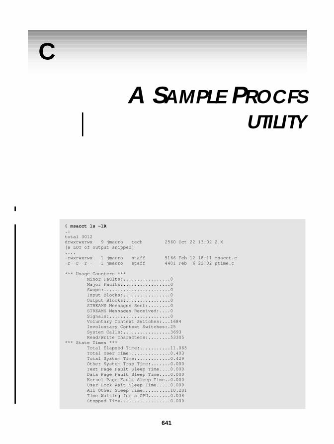
C
A SAMPLE PROCFSUTILITY
$ msacct ls -lR.:total 3012drwxrwxrwx 9 jmauro tech 2560 Oct 22 13:02 2.X[a LOT of output snipped]....-rwxrwxrwx 1 jmauro staff 5166 Feb 12 18:11 msacct.c-r--r--r-- 1 jmauro staff 4401 Feb 6 22:02 ptime.c
*** Usage Counters *** Minor Faults:.................0 Major Faults:.................0 Swaps:........................0 Input Blocks:.................0 Output Blocks:................0 STREAMS Messages Sent:........0 STREAMS Messages Received:....0 Signals:......................0 Voluntary Context Switches:...1684 Involuntary Context Switches:.25 System Calls:.................3693 Read/Write Characters:........53305*** State Times *** Total Elapsed Time:...........11.065 Total User Time:..............0.403 Total System Time:............0.429 Other System Trap Time:.......0.000 Text Page Fault Sleep Time....0.000 Data Page Fault Sleep Time....0.000 Kernel Page Fault Sleep Time..0.000 User Lock Wait Sleep Time.....0.000 All Other Sleep Time..........10.201 Time Waiting for a CPU........0.038 Stopped Time..................0.000
641

642 A Sample Procfs utility
/* * Turn on microstate accounting, and print all field resource * usage and microstat accounting fields when process terminates. * * Borrowed largely from ptime.c * (Thanks Roger Faulkner and Mike Shapiro) * * Usage: msacct command * */
#include <sys/types.h>#include <sys/time.h>#include <procfs.h>#include <stdio.h>#include <stdlib.h>#include <unistd.h>#include <fcntl.h>#include <string.h>#include <errno.h>#include <math.h>#include <wait.h>#include <signal.h>
static int look(pid_t);static void hr_min_sec(char *, long);static void prtime(char *, timestruc_t *);static int perr(const char *);
static void tsadd(timestruc_t *result, timestruc_t *a, timestruc_t *b);static void tssub(timestruc_t *result, timestruc_t *a, timestruc_t *b);
static char *command;static char procname[64];
main(int argc, char **argv){ int ctlfd; long ctl[2]; pid_t pid; struct siginfo info; int status;
if ((command = strrchr(argv[0], ’/’)) != NULL) command++; else command = argv[0];
if (argc <= 1) { (void) fprintf(stderr, "usage:%s command [ args ... ]\n", command); (void) fprintf(stderr, " (time a command using microstate accounting)\n"); return (1); }
switch (pid = fork()) { case -1: (void) fprintf(stderr, "%s: cannot fork\n", command); return (2); case 0: /* newly created child process */ /* open the /proc ctl file and turn on microstate accounting */ (void) sprintf(procname, "/proc/%d/ctl", (int)getpid()); ctlfd = open(procname, O_WRONLY);

643
ctl[0] = PCSET; ctl[1] = PR_MSACCT; (void) write(ctlfd, ctl, 2*sizeof (long)); (void) close(ctlfd); (void) execvp(argv[1], &argv[1]); (void) fprintf(stderr, "%s: exec failed\n", command); if (errno == ENOENT) _exit(127); else _exit(126); }
(void) sprintf("%d", procname, (int)pid); /* for perr() */ (void) signal(SIGINT, SIG_IGN); (void) signal(SIGQUIT, SIG_IGN); (void) waitid(P_PID, pid, &info, WEXITED | WNOWAIT);
(void) look(pid);
(void) waitpid(pid, &status, 0);
if (WIFEXITED(status)) return (WEXITSTATUS(status)); else return ((status & ~WCOREFLG) | 0200);}
static intlook(pid_t pid){ char pathname[100]; int rval = 0; int fd; prusage_t prusage; timestruc_t real, user, sys; prusage_t *pup = &prusage;
(void) sprintf(pathname, "/proc/%d/usage", (int)pid); if ((fd = open(pathname, O_RDONLY)) < 0) return (perr("open usage"));
if (read(fd, &prusage, sizeof (prusage)) != sizeof (prusage)) rval = perr("read usage"); else { real = pup->pr_term; tssub(&real, &real, &pup->pr_create); user = pup->pr_utime; sys = pup->pr_stime; tsadd(&sys, &sys, &pup->pr_ttime); (void) fprintf(stderr, "\n"); printf("*** Usage Counters *** \n"); printf("Minor Faults:.................%ld\n", pup->pr_minf); printf("Major Faults:.................%ld\n", pup->pr_majf); printf("Swaps:........................%ld\n", pup->pr_nswap); printf("Input Blocks:.................%ld\n", pup->pr_inblk); printf("Output Blocks:................%ld\n", pup->pr_oublk); printf("STREAMS Messages Sent:........%ld\n", pup->pr_msnd); printf("STREAMS Messages Received:....%ld\n", pup->pr_mrcv); printf("Signals:......................%ld\n", pup->pr_sigs); printf("Voluntary Context Switches:...%ld\n", pup->pr_vctx); printf("Involuntary Context Switches:.%ld\n", pup->pr_ictx); printf("System Calls:.................%ld\n", pup->pr_sysc); printf("Read/Write Characters:........%ld\n", pup->pr_ioch); printf("*** State Times *** \n"); prtime("Total Elapsed Time:...........", &real);

644 A Sample Procfs utility
prtime("Total User Time:..............", &user); prtime("Total System Time:............", &sys); prtime("Other System Trap Time:.......", &pup->pr_ttime); prtime("Text Page Fault Sleep Time....", &pup->pr_tftime); prtime("Data Page Fault Sleep Time....", &pup->pr_dftime); prtime("Kernel Page Fault Sleep Time..", &pup->pr_kftime); prtime("User Lock Wait Sleep Time.....", &pup->pr_ltime); prtime("All Other Sleep Time..........", &pup->pr_slptime); prtime("Time Waiting for a CPU........", &pup->pr_wtime); prtime("Stopped Time..................", &pup->pr_stoptime); }
(void) close(fd); return (rval);}
static voidhr_min_sec(char *buf, long sec){ if (sec >= 3600) (void) sprintf(buf, "%ld:%.2ld:%.2ld", sec / 3600, (sec % 3600) / 60, sec % 60); else if (sec >= 60) (void) sprintf(buf, "%ld:%.2ld", sec / 60, sec % 60); else { (void) sprintf(buf, "%ld", sec); }}
static voidprtime(char *name, timestruc_t *ts){ char buf[32];
hr_min_sec(buf, ts->tv_sec); (void) fprintf(stderr, "%s%s.%.3u\n", name, buf, (u_int)ts->tv_nsec/1000000);}
static intperr(const char *s){ if (s) (void) fprintf(stderr, "%s: ", procname); else s = procname; perror(s); return (1);}
static voidtsadd(timestruc_t *result, timestruc_t *a, timestruc_t *b){ result->tv_sec = a->tv_sec + b->tv_sec; if ((result->tv_nsec = a->tv_nsec + b->tv_nsec) >= 1000000000) { result->tv_nsec -= 1000000000; result->tv_sec += 1; }}
static voidtssub(timestruc_t *result, timestruc_t *a, timestruc_t *b){ result->tv_sec = a->tv_sec - b->tv_sec;

645
if ((result->tv_nsec = a->tv_nsec - b->tv_nsec) < 0) { result->tv_nsec += 1000000000; result->tv_sec -= 1; }}

646 A Sample Procfs utility

BIBLIOGRAPHY
1. Bach, M. J., The Design of the UNIX Operating System, Prentice Hall, 1986.2. Bonwick, Jeff, The Slab Allocator: An Object-Caching Kernel Memory Alloca-
tor. Sun Microsystems, Inc. White paper.3. Bourne, S. R., The UNIX System, Addison-Wesley, 1983.4. Catanzaro, B., Multiprocessor System Architectures, Prentice Hall, 1994.5. Cockcroft, A., Sun Performance and Tuning — Java and the Internet, 2nd
Edition, Sun Microsystems Press/Prentice Hall, 1998.6. Cockcroft, A., CPU Time Measurement Errors, Computer Measurement
Group Paper 2038, 1998.7. Cypress Semiconductor, The CY7C601 SPARC RISC Users Guide, Ross Tech-
nology, 1990.8. Eykholt, J. R., et al., Beyond Multiprocessing — Multithreading the SunOS
Kernel, Summer ‘92 USENIX Conference Proceedings.9. Gingell, R. A., Moran, J. P., Shannon, W. A., Virtual Memory Architecture in
SunOS, Proceedings of the Summer 1987 USENIX Conference.10.Goodheart, B., Cox, J., The Magic Garden Explained — The Internals of
UNIX System V Release 4, Prentice Hall, 1994.11.Hwang, K., Xu, Z., Scalable Parallel Computing, McGraw-Hill, 1998.12.Intel Corp, The Intel Architecture Software Programmers Manual, Volume 1,
2 and 3, Intel Part Numbers 243190, 24319102, and 24319202, 1993.13.Kleiman, S. R., Vnodes: An Architecture for Multiple File System Types in
Sun UNIX, Proceedings of Summer 1986 Usenix Conference.14.Kleiman, S., Shah, D., Smaalders, B., Programming with Threads, Prentice
647

648 Bibliography
Hall, SunSoft Press, 1996.15.Leffler, S. J., McKusick, M. K., Karels, M. J., Quarterman, J.S., The Design
and Implementation of the 4.3BSD UNIX Operating System, Addison-Wesley,1989.
16.Lewis, B., Berg, D. J., Threads Primer. A Guide to Multithreaded Program-ming, SunSoft Press/Prentice Hall, 1996.
17.Lewis, B., Berg, D. J., Multithreaded Programming with Pthreads. SunMicrosystems Press/Prentice Hall. 1998
18.McKusick, M. K., Bostic, K., Karels, M. J., Quarterman, J. S., The Design andImplementation of the 4.4 BSD Operating System, Addison-Wesley, 1996.
19.McKusick, M. K., Joy, W., Leffler, S., Fabry, R., A Fast File System for UNIX,ACM Transactions on Computer Systems, 2(3):181--197. August 1984.
20.Moran, J. P., SunOS Virtual Memory Implementation, Proceedings of 1988EUUG Conference.
21.Pfister, G., In Search of Clusters, Prentice Hall, 1998.22.Rosenthal, David S., Evolving the Vnode Interface, Proceedings of Summer
1990 USENIX Conference.23.Schimmel, C., UNIX Systems for Modern Architectures, Addison-Wesley,
1994.24.Seltzer, M., Bostic, K., McKusick, M., Staelin, C. An Implementation of a
Log-Structured File System for UNIX, Proceedings of the Usenix Winter Con-ference, January 1993.
25.Shah, D. K., Zolnowsky, J., Evolving the UNIX Signal Model for LightweightThreads, Sun Proprietary/Confidential Internal Use Only, White paper, Sun-Soft TechConf ‘96.
26.Snyder, P., tmpfs: A Virtual Memory File System, Sun Microsystems Whitepaper.
27.SPARC International, System V Application Binary Interface — SPARC Ver-sion 9 Processor Supplement, 1997.
28.Sun Microsystems, Writing Device Drivers - Part Number 805-3024-10, SunMicrosystems, 1998
29.Sun Microsystems, STREAMS Programming Guide - Part Number805-4038-10, Sun Microsystems, 1998
30.Sun Microsystems, UltraSPARC Microprocessor Users Manual - Part Num-ber 802-7220, Sun Microsystems, 1995.
31.Stevens, W. R., Advanced Programming in the UNIX Environment, Addi-son-Wesley, 1992.
32.Stevens, W. R., UNIX Network Programming, Volume 2. Interprocess Commu-nication. 2nd Edition. Addison-Wesley, 1998.
33.Tanenbaum, A. Operating Systems: Design and Implementation. Prentice

Bibliography 649
Hall, 1987.34.Tucker, Andy, Scheduler Activations, PSARC 1996/021, Sun Internal Propri-
etary Document. March, 1996.35.Tucker, Andy, Scheduler Activations in Solaris, SunSoft TechConf ‘96. Sun
Proprietary/Confidential – Internal Use Only Document.36.Talluri, M., Use of Superpages and subblocking in the address translation
hierarchy, Thesis for the doctorate of Computer Science, 199537.Tucker, Andy, Private Communication.38.UNIX Software Operation, System V Application Binary Interface – UNIX
System V. Prentice Hall/UNIX Press. 1990.39.Vahalia, U., UNIX Internals — The New Frontiers, Prentice Hall, 1996.40.Van der Linden, P., Expert C Programming — Deep C Secrets, SunSoft
Press/Prentice Hall, 1994.41.Weaver, D., Germond, T., (editors), The SPARC Architecture Manual, Version
9, Prentice Hall, 1994.42.Wong, B., Configuration and Capacity Planning on Sun Solaris Servers, Sun
Microsystems Press/Prentice Hall, 1996.43.Zaks, Rodney, Programming the Z80, Sybex Computer Books, 1982.

650 Bibliography

INDEX
Symbols%ipf 600/dev/zero 153/etc/name_to_sysnum 44/etc/system 621/proc 23, 164_FILE_OFFSET_BITS 520_LARGEFILE64_SOURCE 520_t_astflag 290_t_post_syscall 290_t_sig_check 290_t_trapret 290“MemTool
Unbundled Memory Tools” on page 275163
Numerics64-bit applications 564-bit data types 564-bit Device Support 51864-bit File Application Programming Inter-
face 51864-bit Files 51764-bit kernel 864-bit support 5
AABS32 210Access Control Lists 531adaptive lock 72add_ivintr() 42add_softintr() 42Address Space 137address space 20, 262address space (process) 263Address Space Identifier 198address space identifier 198advise() 146AF_UNIX 483agent LWP 318aio_read 489align 230alloc 231alloc_fail 231allocate_vfssw() 554Allocation and Storage 526amp 153ani_free 156anon header 155anon slot 155, 159anon_alloc() 155, 159anon_copy_ptr() 155anon_create() 155
651

652 Index
anon_decref() 156anon_dup() 156anon_free 54anon_free() 156anon_get_next_ptr() 156anon_get_ptr() 156anon_getpage() 156anon_map_getpages() 156anon_pages() 156anon_private() 156anon_release() 156anon_resvmem() 156anon_set_ptr() 156anon_unresv() 156anon_zero() 156anoninfo 162anonmap_alloc() 156anonmap_free() 156anonymous 610anonymous map pointer 153anonymous memory 147, 153Anonymous Memory Accounting 161Anonymous Memory Layer 155anonymous memory, 126applets 429–??Application Binary Interface 267argv 298array 300as_addseg() 139as_alloc() 138, 139as_clearwatch() 139as_ctl() 139as_dup() 138, 139as_exec() 139as_fault() 139as_findseg() 139as_free() 139as_gap() 139as_getmemid() 139as_getprot() 139as_map() 139as_memory() 139as_pagelock() 139as_pagereclaim() 140as_pageunlock() 140as_rangebroadcast() 140as_rangelock() 140as_rangeunlock() 140as_rangewait() 140
as_setat() 140as_setprot() 140as_setwatch() 140as_swapout() 140as_unmap() 140ASI 198asymmetric multiprocessor 4async_request_size 189Asynchronous I/O 502AT&T 5atomic 63attaches 141attaching 150autofs 24, 525availrmem 159, 164
Bback hand 180backing store 126bdev_strategy() 550, 593Berkeley labs 4Bill Joy 577Bin Hopping 177biowait() 505Block Buffer Cache 604block buffer cache 593block cache 601Block Size 530Block-Based Allocation 526bmap_read() 592bmap_write() 592boot block 582bootblk 582bootblock 107bootstrap 208BSD 23BSD 4.1 4BSD UNIX 4buddy allocator 7buf_avail 231buf_constructed 231buf_inuse 231buf_max 231buf_size 230buf_total 231buffer cache 593bufhwm 604
Cc 611
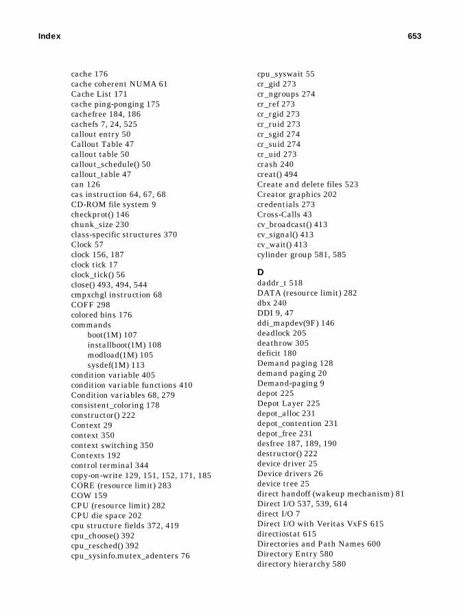
Index 653
cache 176cache coherent NUMA 61Cache List 171cache ping-ponging 175cachefree 184, 186cachefs 7, 24, 525callout entry 50Callout Table 47callout table 50callout_schedule() 50callout_table 47can 126cas instruction 64, 67, 68CD-ROM file system 9checkprot() 146chunk_size 230class-specific structures 370Clock 57clock 156, 187clock tick 17clock_tick() 56close() 493, 494, 544cmpxchgl instruction 68COFF 298colored bins 176commands
boot(1M) 107installboot(1M) 108modload(1M) 105sysdef(1M) 113
condition variable 405condition variable functions 410Condition variables 68, 279consistent_coloring 178constructor() 222Context 29context 350context switching 350Contexts 192control terminal 344copy-on-write 129, 151, 152, 171, 185CORE (resource limit) 283COW 159CPU (resource limit) 282CPU die space 202cpu structure fields 372, 419cpu_choose() 392cpu_resched() 392cpu_sysinfo.mutex_adenters 76
cpu_syswait 55cr_gid 273cr_ngroups 274cr_ref 273cr_rgid 273cr_ruid 273cr_sgid 274cr_suid 274cr_uid 273crash 240creat() 494Create and delete files 523Creator graphics 202credentials 273Cross-Calls 43cv_broadcast() 413cv_signal() 413cv_wait() 413cylinder group 581, 585
Ddaddr_t 518DATA (resource limit) 282dbx 240DDI 9, 47ddi_mapdev(9F) 146deadlock 205deathrow 305deficit 180Demand paging 128demand paging 20Demand-paging 9depot 225Depot Layer 225depot_alloc 231depot_contention 231depot_free 231desfree 187, 189, 190destructor() 222device driver 25Device drivers 26device tree 25direct handoff (wakeup mechanism) 81Direct I/O 537, 539, 614direct I/O 7Direct I/O with Veritas VxFS 615directiostat 615Directories and Path Names 600Directory Entry 580directory hierarchy 580

654 Index
Directory Name Cache 615Directory Name Lookup Cache 568directory name lookup cache 6dirty page 126dirty pages 147discovered direct I/O 615disp() function 388dispadmin(1M) 355, 365dispatch latency 353dispatch queue 371dispatch queue structure 373dispatch queues 350dispatch tables 262, 362dispatcher 16, 41, 266dispatcher lock 68dispatcher locks (description) 97dispatcher priorities 41dispatcher queue insertion 388dispather
queue selection 389DLPI 10DMA 26, 614DNLC 568, 600, 616DNLC Operation 569dnlc_enter() 573dnlc_lookup() 570, 572dnlc_purge() 573dnlc_purge_vp() 573dnlc_remove() 573dnlc_update() 572door client 473door creation 473door interfaces
door_bind 470door_call 469door_create(3X) 469door_cred 470door_info 470door_return 470door_revoke 469door_server_create 470
door_call(3X) 469door_create(3X) 469doorfs 482Doors 7doors 18, 469dump() 146dup() 146, 494dup(2) 500
dynamic file system caching 9Dynamic linking 6dynamic linking 267Dynamic reconfiguration 7dynamically linked libraries 126dyncachefree 609
EE10000 178, 612EISA 26ELF 300elfexec() 300empty_magazines 231ENOENT 566ENOTSUP 505Enterprise Server 10000 193envp 298Ethernet 9Exclusive open 496exec 295, 299exec() 138exec(2) 294, 298, 484exec_core 298exec_func 298exec_lock 299exec_magic 298Executable and Linking Format 267Executable data 131, 147Executable text 131, 147Execution Context 29exit() 137, 303exit(2) 302Extended 64-bit Data Types 521Extent-Based Allocation 527
FF_GETFD 495FAPPEND 497Fast Trap System Calls 46fastscan 181, 187fault() 146faulta() 146fbdwrite() 567fbread() 567fbrelse() 567fbrelsei() 567fbwrite() 567fbwritei() 567fbzero() 567FCLOSEXEC 484, 499

Index 655
FCLOSING 484fcntl() 494fcntl(2) 495FD_SETSIZE 485FDDI 9FDSYNC 498FFS 577fifofs 25, 525figure
list of xxxiFile Caching 601file descriptor 483file descriptor limits 485File Descriptors 22File Handles 492file I/O 481FILE structure 485, 490File Structures 486File System Cache 601file system cache 171File system caching 543file system caching 9File System Capacity 529file system framework 541File System Interface 542File System Layout 581file system page cache 235File System Performance 611File System Switch 552File System Types 524File Systems 11file systems 9File type 579file types 482
Block special 482Character special 482Directory 482Door 482Named pipe 482Regular 482Socket 483Symbolic link 482
Files 481files 22filestat 587floating point exceptions) 19Floating-point exceptions 32FLTWATCH 165force directio 614
forceload 105fork 275, 294fork() 137, 279fork(2) 294fork_fail_pending 297fork1 295forklwp 305fragmentation 218Free List 171free memory 152free() 146freemem 54freeproc() 303front hand 180FRSYNC 498fsflush 114FSIZE (resource limit) 282fstat() 494fstyp 587fstyp -v 588FSYNC 498ftok(3C) 430full_magazines 231
Ggenunix 104, 106getfacl 532gethrtime 319gethrtime() 47gethrvtime() 47getmemid() 146getoffset() 146getpid() 47getprot() 146gettype() 146getvfs() 554, 556getvp() 147gexec() 301GID 273gid 579global_alloc 231global_free 231graphics adapters 145graphics performance 202
Hhandspreadpages 180, 187hardswap 359Hardware Address Translation Layer 190hardware buffering 65

656 Index
hardware context 266hardware context (process) 262Hardware Translation Acceleration 193hash_lookup_depth 231hash_rescale 231hash_size 231HAT 9, 20, 140, 170, 190, 208, 210hat_alloc() 191hat_chgattr() 192hat_clrattr() 192hat_free_end() 192hat_free_start() 192hat_get_mapped_size() 192hat_getattr() 192hat_map() 148hat_memload() 192hat_setattr() 192hat_stats_disable() 192hat_stats_enable() 192hat_swapin() 192hat_swapout() 192hat_sync() 192hat_unload() 192Heap 147heap 135, 185Heap space 131High-Resolution Clock Interrupts 56High-Resolution Timer 57hires_tick 56, 113hment 196holdcnt 87, 88hsfs 24, 525HSM 539
II/O Bus and Device Management 11I/O devices 25I/O system 9IA 9, 16ia_set_process_group() 386IBM’s AIX 158ICL 5IDLE 55in-core (in-memory) inode 597incore() 147indirect blocks 584, 601Informix 203init 114Inode Idle List 598Inode number 579
Inodes 597installboot 582Instruction exceptions 32Intel Address Space 134Intel Pentium 193Intel x86 8, 174Interactive priorities 351Interprocess communication
identifier 430key 430object permission 431POSIX 459System V 430
interrupt 28, 29interrupt block cookie 75Interrupt Context 29interrupt handler 38Interrupt Handlers 30interrupt latency 8Interrupt Monitoring 42Interrupt priorities 351interrupt priority levels 38Interrupt Thread Priorities 41Interrupts 38interrupts 9, 26, 27Interrupts as Threads 39Intimate Shared Memory 145Intimate shared memory 440intimate shared memory 203iowait 55IPC 17IPC_RMID 439ipcaccess() 430ipcget() 430, 432ipcrm(1) 439ipcs 239ISDN 9ISM 145issig() 340Itanium 5ITOV 598iv_pil 42
Jjitter 54Journaling 532
Kk_anoninfo 162k_anoninfo.ani_free 164

Index 657
k_anoninfo.ani_max 164k_anoninfo.ani_mem_resv 164k_anoninfo.ani_phys_resv 164k_sigset_t 330kaio 504, 507kanon_info 162kas 633Kernel Address Space 206, 211kernel address space 633Kernel Asynchronous I/O 504Kernel Context 29kernel data-segment 208Kernel Facilities (Clocks, timers, etc.) 11Kernel Management Threads 30kernel map 206Kernel Memory 205kernel memory 125Kernel Memory Allocation 212kernel memory debugging 232Kernel Memory Management 21Kernel Memory Segment Driver 214kernel mode 27kernel mode priorities 367kernel modules
directory tree 105loading 113types 104
Kernel Overview 10kernel preempt queue 369kernel preemption 371, 394Kernel Services 27kernel stack 293Kernel Text 208kernel text 202, 206Kernel Text and Data Segments 208kernel thread 264, 287kernel threads 14kernel tunable parameters 622kernel tuneables
autoup 626bufhwm 627cachefree 625consistent_coloring 629desfree 625doiflush 626dopageflush 626fastscan 624handspreadpages 626hires_tick 630
kmem_debug_enable 629kmem_flags 629kobj_map_space_len 629lotsfree 624max_nprocs 630maxpgio 626maxphys 627maxpid 630maxuprc 630maxusers 628min_percent_cpu 625minfree 625moddebug 629msgmap 624msgmax 624msgmnb 624msgmni 624msgseg 624msgssz 624msgtql 624nautopush 631ncsize 627ndquot 627ngroups_max 628noexec_user_stack 630npty 628nrnode 627nstrpush 631pageout_reserve 625pages_before_pager 626pages_pp_maximum 625physmem 629priority_paging 625pt_cnt 628rechoose_interval 630reserved_procs 630rlim_fd_cur 628rlim_fd_max 628rstchown 628sadcnt 631segspt_minfree 623semaem 623semmap 623semmni 623semmns 623semmnu 623semmsl 623semopm 623semume 623

658 Index
semvmx 623shmmax 623shmmin 623shmmni 623shmseg 623slowscan 624strctlsz 631strmsgsz 631swapfs_minfree 628swapfs_reserve 628throttlefree 625timer_max 629tmpfs_maxkmem 627tmpfs_minfree 627tune_t_flushr 626tune_t_minarmem 625ufs
ufs_HW 627ufs_LW 627ufs_WRITES 627
ufs_ninode 627Kernel Virtual Address Maps 633Kernel Virtual Memory 205Kernel Virtual Memory Layout 205kernel/unix 208Kessler’s Best Bin 178kill(2) 325Kirk McKusick 577kluster() 147klustsize 189kmem_cache_alloc() 219, 222kmem_cache_create( 219kmem_cache_create() 220, 222kmem_cache_destroy() 219, 222kmem_cache_free() 222kmem_cache_stat() 222kmem_content_maxsave 233kmem_depot_contention 227kmem_flags 231kmem_freepages() 217kmem_getpages() 216, 217kmem_log_size 233kmem_reap_interval 227kmem_reapahead 228kmem_update_interval 226kpreempt() 398kpreemptpri 389krtld 109, 110ktextseg 634
kvalloc 634kvseg32 634
LL2 cache 175large devices 518Large Pages 202Large pages 200Large-File 519Large-File Compilation Environmen 520Large-File Summit 520Large-page support 7latency 61lbolt 55ldstub instruction 64, 67, 68libaio 503library file 132Lightweight process 210lightweight process 14, 205, 264limit(1) 282links 22, 579Linux 602load/store buffers (hardware) 66Loadable file system modules 543lock object operations vector 70lock primitives 63lock waiters bit 76lock wakeup behaviour 81lock_set() function 98lock_set_spl() function 98Locking statistics 7lockop() 147lockstat 76lockstat(1M) 77, 82Log structured 533logging 533Logging (Journaling) File Systems 532Logging UFS 7lookuppn() 566lotsfree 180, 181, 184, 186, 607LP64 8lrusage 318lseek() 494lstat() 494LWP 165, 503LWP pool activation 417lwp_ap 286lwp_asleep 286lwp_create 507lwp_create() 375

Index 659
lwp_curinfo 286lwp_cursig 286lwp_errno 286lwp_error 286lwp_exit 304lwp_kill(2) 325lwp_mstate 321lwp_pcb 286lwp_procp 286lwp_scall_start 286lwp_sigaltstack 286lwp_siginfo 286lwp_sigoldmask 286lwp_stime 286lwp_thread 286lwp_utime 286
Mm_owner 78m_owner field 75m_spinlock field 75machine state 286MADV_DONTNEED 513MADV_RANDOM 513MADV_SEQUENTIAL 513MADV_WILLNEED 513Magazine Sizes 226magazine_size 231magazines 225magic(4) 298main(), kernel function 110major page faults 141malloc() 131, 135, 158MAP_FIXED 511MAP_NORESERVE 511MAP_PRIVATE 151, 152, 153, 157, 159,
511MAP_SHARED 151, 511mapelfexec() 301Mapped files 147mapped shared 132Mapping Files 512mapping of files 4Mapping Options 511Massively parallel processor 60max_nprocs 112, 291, 293, 570max_percent_cpu 185maxpgio 187, 190, 611MAXPID 279, 293maxpid 112
MAXSIG 325maxslp 190maxuprc 112, 292maxusers 111, 291, 570memcntl() 560memcntl(2) 353memory barrier (membar) instructions 68memory barrier instructions 67Memory free 235memory hardware 125memory locking 353Memory Management 11Memory management exceptions 32memory model 66, 67Memory Monitoring 235Memory Monitoring Tools 239memory page locking 442Memory Scheduler 189Memory Shortage 237Memory used by processes 235Memory used for the file system page cache
235memory utilization 235Memory, File System Caching Memory 236Memory, Free Memory 236Memory, Kernel Memory 236Memory, Total Physical Memory 236memory_class 231memps 247memstat 239, 254, 610MemTool 163, 235, 239, 245message header 455Message queue limits
msgmap 452msgmax 453msgmnb 453msgmni 453msgseg 454msgssz 454msgtql 453
Metadata 534, 593Metadata logging 533MicroSPARC 193microSPARC 174microstates 321min_percent_cpu 185minfree 187minor faults 150minor page faults 141

660 Index
mknod 17mlock(3C) 353mmap() 148, 150, 510, 558mmap(2) 429, 461MMU 21, 127, 141, 149, 152, 193, 197MMU-Generated Traps 200MMU-Specific Page Structures 169mod_install 119mod_modinfo structure 118mod_ops structure 120modctl structure 119modinfo 106modload(), kernel function 117modload(1M) 435module loading 12Module Text and Data 209mount 614mpstat 42mpstat(1M) 88mq_maxmsq 466mq_maxsz 466mq_open(3R 465mq_receive(3R) 465mq_send(3R) 465MS-DOS file system 9msgmap 433, 454msqid_ds 453, 455multiple processors 4Multiprocessor 60multiprocessor 4Multithreaded 8Multithreaded applications 63Multithreaded kernel 8mutex locks 65, 71MUTEX_DEFAULT 75mutex_exit() function 74mutex_init() function 74, 76mutex_sobj_ops 71MUTEX_SPIN 75mutex_vector_enter() function 75, 76mutex_vector_exit() function 77mutual exclusion lock 68
Nncsize 112, 570, 616ndquot 112nested traps 34Network file system 541Network File Systems 23Networking 11
nextofkin 278nexus driver 25NFPCHUNK 283NFS 4, 535, 607nfs 24, 525ngroups_max 112nice(1) 376NIS 4NOFILE (resource limit) 283non_anon() 156Nonblocking I/O 496nonpageable 205nonuniform memory access 61Nucleus 199, 209
OO_APPEND 497O_CREAT 496O_DSYNC 498O_EXCL 496, 497O_NDELAY 495, 496O_NONBLOCK 495, 496O_RSYNC 498O_SYNC 498Object Caching 220off_t 517on-disk inode 597ONPROC 275open 17Open Boot 208open() 493, 494, 544, 569OpenBoot PROM 107Oracle 203
Pp_as 271p_child 276p_cred 273p_cstime 279p_cutime 279p_exec 271p_filesz 301p_holdlwps 279p_lwpblocked 279p_lwpcnt 279p_lwptotal 279p_memsz 301p_mlreal 320p_mstart 297p_next 276

Index 661
p_nextofkin 276p_nextorph 276p_orphan 276p_parent 276p_pglink 276p_pgpidp 278p_pidp 278p_ppglink 276p_ppid 275p_prev 276p_prof 280p_psibling 276p_sessp 278p_sibling 276p_sig 338p_stat 274p_stime 279p_tlist 279p_utime 279p_zombcnt 279p_zomblist 279, 304Page Cache 602Page coloring 172page coloring 176Page Coloring Algorithms 177page faul 141page fault 152Page Hash List 168Page Lists 170Page Management 167Page Protection and Advice 152Page reclaims 172Page Scanner 178page scanner 21Page Scanner Implementation 187Page Scanner Operation 179Page Scanner Parameters 186Page Sizes 173page table entries 195Page Tables 209Page Throttle 173page_create() 172page_create_va() 172, 176, 213page_exists() 172page_find() 168, 172page_first() 172page_free() 171, 172page_hash 168PAGE_HASH_SEARCH 169
page_isfree() 172page_ismod() 172page_isref() 172page_isshared() 172page_lookup() 168, 172, 173page_lookup_nowait() 168, 173page_needfree() 173page_next() 173Pageable Kernel Memory 210Paged Vnodes 548page-in 126page-ins 606pageio_done() 550pageio_setup() 550Page-Level Interfaces 172pagelock() 147page-out 126pageout 114pageprot 152pages 126Pages - Locating 169pages_before_pager 607page-stealing 183Paging Counters 242Paging Parameters 611parallel architectures 62Partial Store Order (PSO) 67Path-Name Management 565Path-Name Traversal 568PC/DOS 541pcfs 24, 525PCMCIA 26PCWATCH 164performance 176, 189pfiles 284, 488Physical memory 129physical memory 20, 235Physical Memory Managemen 127physical page list 188physical page number 195Physical Swap Space 238pi_willto() function 88, 96PID 278pid_assign() 297pid_pgorphaned 278pid_prinactive 278pid_prslot 278PIL 98pinned thread 40
662 Index
pipe 17Pipes 22pirec structure 94platform 104pmap 239pmap(1) 272pn_alloc() 568pn_fixslash() 568pn_free() 568pn_get() 568pn_getcomponent() 568pn_getsymlink() 568pn_insert() 568pn_set() 568pn_setlast() 568pn_skipslash() 568po_share 183poll() 494poll(2) 283POSIX IPC 18
Internal functions 460internal functions 459
post_syscall() 297power management 6pr_read_psinfo() 314pr_size 165pr_vaddr 165pread 489pread and pwrite 501pread() 494Preempting 43preemption 16preemption control 380preemptive 350prinit() 309priocntl(1) 355, 377priocntl(2) 355priority inheritance 94priority inheritance (description) 89Priority Interrupt Level (PIL) 73, 76Priority inversion 352priority inversion (description) 89Priority Paging 7Priority paging 179priority paging 608Priority Paging Algorithm 183priority ranges 17priority_paging 183, 186, 609Private 243
privileged execution mode 31privileged instructions 32procdir 310process 10, 261Process Context 29process context 269process control block 286Process execution and scheduling 11Process Execution Time Statistics 55Process groups 263process groups 342process image 267process model 262Process Priorities 16process states 274process status 274process structure 269process table 261, 290processes 14Processes, Threads, and Scheduling 14processing capacity 4processor binding 426processor control block 421processor interrupt level (PIL) 33Processor partitioning and binding 9Processor resets 32processor sets 7, 372, 426processor state 31processor states 422processor_bind(2) 426Procfs 262procfs 25, 306, 525Program Header Table 268PROM 208PROT_EXEC 512PROT_NONE 512PROT_READ 151, 512PROT_WRITE 151, 512protection faults 141Protection Modes 140prtmem 237, 607prtswap 163, 248prwatch 165ps 239ps(1) 261pset_bind(2) 426Pseudo File Systems 23psrset(1M) 369pthread_create(3T) 264, 265

Index 663
PTHREAD_SCOPE_SYSTEM 265pthread_setconcurrency(3T) 265pu_sysinfo.rw_rdfails 88putpage() 160pvn_getdirty() 549pvn_plist_init() 549pvn_read_done() 549pvn_read_kluster() 549pvn_vplist_dirty() 550pvn_write_done() 549pvn_write_kluster() 550pwrite 489pwrite() 495
QQFS 528qfs 525Quotas 539
RRAM 125, 168read() 495, 544read() and write() system calls 558readdir() 600reader/writer (RW) lock 68reader/writer (RW) locks 65read-modify-write 63readv 489readv and writev 502readv() 495Real-time 10realtime 353Realtime priorities 351realtime_timeout() 47rechoose_interval 390reclaim() 222reclaiming 172RED state 32registers 26Regular (On-Disk) File Systems 525Relaxed Memory Order (RMO) 67reserved_procs 291Resource Map Allocator 214resource maps 433resume() 404resume_from_intr() function 97rlim_cur 282rlim_fd_cur 484rlim_fd_max 484rlim_max 282
rlimit 282RLIMIT_VMEM 301rlimits 113rmalloc() 214, 215rmalloc_locked() 215rmalloc_wait() 215rmallocmap() 214, 215rmallocmap_wait() 215rmfree() 215rmfreemap() 214, 215rmget() 215root vnode 573rootvfs 554, 555rounds 225RPC 4rstchown 112RT 9, 16rt_enterclass() 387rt_globpri 368rt_quantum 368RUN 274runtime linker 267rw_enter() function 82rw_enter_sleep() function 83, 84rw_exit() function 82rw_exit_wakeup() function 85rw_init() function 82rw_rdfails 84rw_sobj_ops 71rw_waiters 86rw_wlock 86rw_wrfails 84rw_wwwh 86
SSA_NOCLDWAIT 302SA_ONSTACK 335SA_SIGINFO 333samfs 525sar -g 599sar -k 236sar -v 619sbrk() 135scalability 4scan rate 184, 606sched process 359schedpaging() 187scheduler activation 380Scheduler activations 352scheduler activations 415

664 Index
scheduler parameters 351schedulers 9Scheduling 16scheduling class 262, 349scheduling class functions 357
admin 357donice 360enterclass 357exitclass 358fork 358forkret 358getclinfo 357getclpri 357globpri 361parmsget 358parmsin 357parmsout 357parmsset 358preempt 360setrun 360sleep 360swapin 359swapout 359swapri 359tick 360trapret 359wakeup 360yield 361
scheduling classes 262, 354sclass structure 355SCSI 26, 504, 524SDLC 9Section Header Table 268Seek 523seg kmem 221seg_dev 145seg_drv 146seg_kmem 145, 212seg_kp 145, 212seg_lock 146seg_map 145, 212, 595seg_map statistics 564seg_mapdev 146seg_mdi 146seg_nf 146, 212seg_spt 145seg_sx 146seg_vn 145, 560segkmem 208
segkmem_checkprot() 216segkmem_create() 216segkmem_getprot() 216segkmem_setprot() 216segkmem32 210segkp 293segmap 206segmap_fault() 593segmap_getmap() 561segmap_getmapfault() 561segmap_pagecreate() 561, 595segmap_pageunlock() 561segmap_release() 561, 595segment 20segment (ELF file) 268segment driver 143Segment drivers 9segmentation violation 141SEGOP_FAULT() 145segvn_create() 144, 148segvn_fault() 149select() 495select(3C) 485select-and-ratify algorithm 403SEM_NSEMS_MAX 463sem_open(3R) 462, 463SEM_VALUE_MAX 463sema_destroy() function 99sema_held() function 99sema_init() function 99sema_p() function 99, 101sema_sobj_ops 71sema_sobj_ops structure 102sema_v() function 99semaphore interfaces 462Semaphore limits
semaem 448semmap 446semmni 446semmns 446semmnu 447semmsl 447semopm 447semume 447semusz 447semvmx 448
semaphore P and V operations 99semaphore value 445semaphores 68
Index 665
semget(2) 445, 450semid_ds 449semmap 433sequential consistency model 66session 342session leader 345set_anoninfo() 156setfacl 532setitimer(2) 57setprot() 147Shared 243Shared libraries 147Shared Mapped Files 150shared memory 4Shared Memory Multiprocessor 60shared program libraries 4sharing program binaries 126SHM_SHARE_MMU 203shmat() 439shmget() 438shmid_ds 435shmmax 436, 437shmmin 436shmmni 436, 437shmseg 436si_pc 166si_trapafter 166siblings (process) 275SIDL 275sigaction 308, 333sigaction(2) 334sigaltstack(2) 335SIGCHLD 329SIGCLD 275, 302SIGDANGER 158siginfo 332, 338SIGIO 503SIGKILL 275signal disposition 325signal generation 331Signals 19signotify 334SIGPROF 56SIGSEGV 139, 141, 513sigsend(2) 325sigtoproc() 337SIGTRAP 165SIGTSTP 343SIGTTIN 343
SIGTTOU 343SIGVTALRM 56SIGWAITING 416SIGXCPU 56, 329SIGXFSZ 329single kernel image 61Slab Allocator 217slab allocator 21Slab Allocator Statistics 229Slab Allocator Tracing 231Slab Cache Parameters 227slab_create 231slab_destroy 231slab_size 231SLEEP 274sleep queues 404sleeping for an I/O 17sleepq_insert() 410sleepq_insert() function 92, 96slowscan 180, 187SMP 6, 59Snapshot 539Sockets 22sockfs 25, 483, 525softcall() 50softswap 359software context (process) 262Software Traps 35Software-initiated traps 32Solaris 2.0 5, 6Solaris 2.1 6Solaris 2.1-x86 6Solaris 2.2 6Solaris 2.3 6Solaris 7 RW lock 83Solaris 8 128, 185Solaris Kernel Architecture 11Solaris Resource Manager 9Solstice Disk Suite (SDS) 578Solstice DiskSuite (SDS) 504SPARC register management 32SPARC V7 132SPARC V9 132SPARCcenter 2000 133, 206Sparse Files 538specfs 24, 525spin lock 72spin locks 72stack 20, 131, 134, 185, 210

666 Index
STACK (resouce limit) 282stacks 205Standard I/O 489standard I/O functions
clearerr() 491fclose() 491feof() 491ferror() 491fflush() 491fgetc() 491fgetpos() 491fgets() 491fileno() 491flockfile() 491fopen() 492fprintf() 492fputc() 492fputs() 492fread() 492freopen() 492fscanf() 492fseek() 492fsetpos() 492ftrylockfile() 492funlockfile() 492fwrite() 492getc() 492getc_unlocked() 492getw() 492pclose() 492popen() 492putc() 492rewind() 492setbuf() 492setvbuf() 492ungetc() 492
stat() 495static linking 267stderr 263stdin 263stdio(3S) 485stdout 263STOP 274Stripe 539struct _sobj_ops 70struct as 138struct FILE 490struct k_anoninfo 162struct machpage 170
struct ncache 571struct pathname 568struct seg 143struct segvn_data 148struct uf_entry 483struct uio 517struct vfs 551struct vnode 545struct vpage 152Sun UNIX 0.7 6sun4u 64-bit kernel address space 206SunOS 1.0 4, 6SunOS 2 4SunOS 2.0 6, 541, 577SunOS 4.0 6, 183SunOS 4.1 4, 6SunOS 4.1.3 6SunOS 4.x binary compatibility 35SunOS 5.0 5SunOS 5.X 5superblock 581, 589SuperSPARC 201SVR3 5SVR4 5swap 168, 239swap device 611swap -l 239swap -s 162, 238Swap Space 238Swap space 158swapctl() 162swapfs 158, 189swapfs Implementation 159swapfs Layer 156swapfs_getpage() 159swapfs_getvp() 159swapfsminfree 164swapout() 147Swapped out 158Swapping 190swapping 128swtch() 400, 401swtch() function 388Symmetric multiprocessing 8Symmetric multiprocessor 60sync() 147synchronization locks 60SYS 16sysdef 604

Index 667
sysent table 44SYSTEM 55system call 28System Call Interface 11System Calls 22, 44system calls 28System Clock 54System priorities 351System V file system 579System V IPC 18System V Message Queues 18System V Semaphores 18System V Shared Memory 18
Tt_affinitycnt 287t_astflag 304t_bind_cpu 288t_bound_cpu 287t_cid 289t_cldata 289t_clfuncs 289t_cpu 289t_cred 289t_disp_queue 289t_disp_time 289t_epri 289t_epri (kernel thread) 96t_epri field (kernel thread field) 92t_hold 289t_kpri_req 83, 87, 289t_lockp 289t_lwp 289t_oldspl 289t_post_syscall 297t_pre_sys 289t_preempt 288t_pri 289, 375t_proc_flag 288t_procp 289t_release_all() function 96t_schedflag 288t_sig 289, 338t_sigqueue 289t_stack 287t_state 288t_sysnum 289t_wchan 289Table
list of xxxvii
Tcc (trap instruction) 35TCP sockets 7TCP/IP 11test-and-set instruction 63The Kernel Map 213THR_BOUND 265thr_create(3T) 264, 265thr_setconcurrency(3T) 265thread creation 10thread stacks 205thread_create() 375thread_create() (function) 91thread_create() function 95thread_reaper 305threading 5throttlefree 187thundering herd problem 78TICK register 320time() 47Time-of-Day Clock 57timeout(9F) 47Timeshare priorities 351timeshare scheduling 17TLB 193, 195, 197, 206, 208, 209TLB effectiveness 201TLB misses 201TLB performance 200tmpfs 24, 525TNF Trace buffers 210Total Store Ordering (TSO) 67TP_MSACCT 321TPC-C 203TPC-D 203Translation Lookaside Buffer 440translation table entries (TTEs) 195trap 28, 29, 133Trap Analysis 36Trap Levels 34Trap Priority Levels 33trap signals 339trap table 31, 206Trap Table Layout 34trap table layout 35trap types 32TRAP_XWATCH 166Traps 31trapstat 36truss 507TS 9, 16
668 Index
TS_FREE 288ts_globpri 364ts_lwait 366ts_maxwait 366TS_ONPROC 288ts_quantum 365TS_RUN 288TS_SLEEP 288TS_SLEEP (thread state) 95ts_sleep() 382ts_sleep() function 412ts_slpret 365TS_STOPPED 288ts_tick() 381, 385ts_tqexp 365ts_update() 384, 385TS_ZOMB 288TSB 196, 197, 206, 208, 209TSB Sizes 198tsdpent structure 364tsm_mutex lock 93tsproc structure fields 378tstile_alloc() function 95tstile_init() function 94tstile_mod structure 93tstile_pointer() function 95TTE 195, 197, 200turnstile (description) 89turnstile_block() function 92turnstile_lookup() function 91turnstile_wakeup() function 85, 92turnstiles 69Two-Level Thread Model 15
Uu_argc 281u_argv 281u_cdir 281u_cmask 282u_comm 281u_dsize 281u_envp 281u_exdata 281u_execid 281u_execsz 281u_flist 283u_flist array 483u_flock 283u_mem 282u_nofiles 283
u_nshmseg 282u_psargs 281u_rdir 281u_rlimit 282u_sigmask 335u_signal 335u_sigonstack 334u_start 281u_ticks 281u_tsize 281u_ttyvp 281UDP 483uf_entry 483uf_fpollinfo 283uf_ofile 283uf_pofile 283uf_refcnt 283UFS 481, 524, 528ufs 24, 525UFS Block Allocation 585UFS Directories 579UFS Inode 579UFS Inode Cache 617UFS Links 581UFS On-Disk Format 579ufs_getpage() 149, 593ufs_getpage(). 593ufs_HW 595ufs_inactive() 598, 599ufs_ipf 600ufs_lookup() 600ufs_LW 595ufs_map() 148ufs_ninode 112, 599, 617, 618, 619ufs_read() 593ufs_readdir() 600ufs_write throttle 595ufs_write() 595ufsboot 107, 108UID 273uid 579uio_resid 567ulimit(1M) 136ulimit(2) 282UltraSPARC 98, 106UltraSPARC I & II Traps 32UltraSPARC Interrupts 42UniSoft 6unix 106

Index 669
Unix File System 577UNIX IPC 17unmap() 147untimeout(9F) 51USER 55user area 281user mode 27user preemption 394user priority 386user threads 15USYNC_PROCESS 463USYNC_THREAD 463utmp 279
Vv.v_proc 310v_data 484v_maxup 291v_maxupttl 291v_proc 291, 293v_type 545VBAD 546VBLK 545VCHR 545VDIR 545VDOOR 545vf_to_stf() 556VFIFO 545vfork 295vfork() 138VFS 6, 9vfs 550, 573vfs switch table 553vfs_add() 555vfs_fstype 553vfs_getvfssw 554vfs_lock 555vfs_make_fsid() 556vfs_mount() 551vfs_mountroot() 551vfs_remove() 555vfs_root() 551vfs_statvfs() 551vfs_swapvp() 551vfs_sync() 551vfs_unlock 555vfs_unmount() 551vfs_vget() 551vfssw 553vfwait() 297
virtual address space 130, 142Virtual File System Framework 23virtual memory 4, 9, 19, 125Virtual Memory Context 29Virtual Memory Contexts 192Virtual Memory System 605Virtual Swap Space 238VLNK 545VM system 126VMEM (resource limit) 283vmstat 42, 239, 240, 606vmstat -s 617VN_HOLD 548VN_RELE 548vnode 168, 597Vnode Methods 546Vnode Types 545VNON 545Volume Management 538vop_access() 546vop_addmap() 546vop_close() 546vop_cmp() 546vop_create() 546vop_delmap() 546vop_dispose() 546vop_dump() 546vop_dumpctl() 546vop_fid() 546vop_frlock() 546vop_fsync() 546vop_getattr() 546vop_getpage 546vop_getpage() 593vop_getsecattr() 546VOP_INACTIVE 548vop_inactive() 546, 598vop_ioctl() 546vop_link() 547vop_lookup() 547, 566, 600vop_map() 547vop_mkdir() 547VOP_OPEN 545vop_open() 547vop_pageio() 547vop_pathconf() 547vop_poll() 547vop_putpage() 547vop_read() 547, 560, 593

670 Index
vop_readdir() 547, 600vop_readlink() 547vop_realvp() 547vop_remove() 547vop_rename() 547vop_rmdir() 547, 600vop_rwlock() 547vop_rwunlock() 547vop_seek() 547vop_setattr() 547vop_setfl() 548vop_setsecattr() 548vop_shrlock() 548vop_space() 548vop_symlink() 548vop_write() 548, 560, 593vpage 152VPROC 313, 545VREG 545VROOT 566VSOCK 546VTOC 108VTOI 597VxFS 526, 528, 607vxfs 525VxFS Inode Cache 620vxfs_ninode 620
WWA_EXEC 165WA_READ 165WA_TRAPAFTER 165WA_WRITE 165WAFL 536WAIT 55wait channel 406wait(2) 302waiters (threads) 69Watchpoint 199Watchpoints 164window spilling, filling 32Windows NT 602wired down 205write throttle 595write() 495, 544write-through caches 66writev 489writev() 495writewanted bit 87, 88wrwant bit 83
wsm 239, 253wtmp 279
XX.25 9
Zzero fill on demand 135zero-fill-on-demand 153ZFOD 153, 159ZOMB 274

Index 671

672 Index

Index 673

674 Index

Index 675

676 Index

Index 677

678 Index

Index 679

680 Index

Index 681

682 Index

Index 683

684 Index

Index 685

686 Index

Index 687

688 Index