solar fuels from concentrated sunlight - solarpaces · the success of solar thermal ... high...
TRANSCRIPT

Solar Fuels fromConcentrated Sunlight
Solar Power and Chemical Energy SystemsImplementing Agreement of theInternational Energy Agency

2 Solar Fuels from Concentrated Sunlight

Contents
4 Executive Summary
6 Intermittent Solar Energy – Need for Storage
6 Why solar fuels? 8 Why solar hydrogen? 9 Solar fuels production
10 In Focus – Solar Concentrating Technologies
10 Solar tower facilities 12 Concentrating solar research facilities
16 Solar Hydrogen – Future Energy Carrier
16 Solar production of hydrogen 18 H2 from H2O by solar thermolysis 18 H2 from H2O by solar thermochemical cycles 21 H2 by decarbonization of fossil fuels 23 H2 from H2S by solar thermolysis
24 Solar Hydrogen – At Competitive Costs!
26 Boosting Solar Fuels – Need for Worldwide R&D
30 Transition to Solar Fuels – Recommended Strategy
30 R&D strategy for solar H2 production 33 R&D needs for solar H2 production
34 Bright Future for Solar Fuels – Outlook
Solar Fuels from Concentrated Sunlight 3
Photos
1 CESA 1 Solar Tower, CIEMAT-PSA, Almería, Spain (DLR)
2 CESA 1 Solar Tower, CIEMAT-PSA, Almería, Spain (DLR/Steur)
7 Blue Sky (PSI)11 SSPS Solar Tower, CIEMAT-PSA,
Almería, Spain (DLR)17 SEDC Solar Energy Development
Center, Rotem, Israel (BrightSource Energy/Eilon Paz)
25 Solar Two, Barstow, USA (Sandia National Laboratories)
27 DLR Solar Furnace, Cologne, Germany (DLR)
31 WIS Solar Tower, Rehovot, Israel (WIS)
35 Heliostat, CIEMAT-PSA, Almería, Spain (DLR/Steur)
36 PS10 & PS20, Sanlúcar La Mayor, Spain (Abengoa Solar)

4 Solar Fuels from Concentrated Sunlight
Sunlight is by far the most abundant carbon-neutral energy resource on earth. However, so-lar energy is intermittent and does not neces-sarily match the variations in demand. If it is to become a major contributor to our energy supply, some form of storage is necessary. Conversion of solar energy into chemical fuels is an attractive method of solar energy stor-age. Solar fuels, such as hydrogen, can be used for upgrading fossil fuels, burned to generate heat, further processed into electrical or me-chanical work by turbines and generators or internal combustion engines, or used directly to generate electricity in fuel cells and batteries to meet energy demands whenever and wher-ever required by the customers. The challenge is to produce large amounts of chemical fuels directly from sunlight in robust, cost-effective ways while minimizing the adverse effects on the environment.The success of solar thermal power genera-tion – known as ‘concentrating solar power’ (CSP) – is already moving towards sustainable, large scale fuel production: concentrating so-lar radiation with re�lecting mirrors provides high temperature process heat for driving ef-�icient thermochemical processes. Although the technical feasibility of various technologies has been demonstrated, commercialization of these processes has been hindered by the economics.Nevertheless, solar fuels are among the most promising technologies to curb the growing demand for fossil fuels and to mitigate the ef-fects of climate change. To achieve this it is rec-ommended that commercial implementation steadily evolves, starting from the current state-of-the-art fossil fuel production technologies. To facilitate the introduction of new solar fuels production processes, the existing know-how from both the fuel production industry and the CSP research institutes should be merged. At a
later stage, the emerging solar fuel technologies will be based on processes that are completely independent of any fossil fuel resources.The main vector for this transformation will be the production of hydrogen, a potentially clean alternative to fossil fuels, especially for use in transport. Today, however, more than 90% of hydrogen is produced by using high tempera-ture processes from fossil resources, mainly natural gas. If hydrogen is generated from solar energy, it is a completely clean technology; no hazardous wastes or climate changing byprod-ucts are formed and only sunshine and water are required as inputs to the process. This is the vision outlined in the European Commission’s ‘European hydrogen and fuel cell roadmap’, which runs up to 2050.
Solar fuels production
There are basically three routes, alone or in combination, for producing storable and trans-portable fuels from solar energy. The electro-chemical route uses solar electricity made from photovoltaic or concentrating solar thermal systems followed by an electrolytic process; the photochemical/photobiological route makes direct use of solar photon energy for photo-chemical and photobiological processes; the thermochemical route uses solar heat at high temperatures followed by an endothermic ther-mochemical process. The thermochemical route offers some intrigu-ing thermodynamic advantages with direct eco-nomic implications.
Concentrating solar technologies
The state-of-the-art CSP technology capable of achieving high process temperatures is the ‘solar tower’ con�iguration, where a �ield of
Executive Summary

Solar Fuels from Concentrated Sunlight 5
heliostats (tracking mirrors) focuses the sun-rays onto a solar receiver mounted on top of a centrally located tower. Such solar concentrat-ing systems already operate in large-scale pi-lot and commercial plants, such as the 11 MWel
PS10 plant near Seville in Spain, in operation since 2007 to deliver solar generated electric-ity to the grid. They make use of a heat transfer �luid (typically air, water, synthetic oil, helium, sodium, or molten salt) that is heated by solar energy and then used in traditional steam or gas turbines. The typical land area required for a 50 MWth plant is about 300,000 m2.Solar thermochemical applications, although not as far advanced as solar thermal electricity generation, employ similar solar concentrat-ing technologies. However, high-temperature thermochemical processes require higher solar concentration than CSP plants, which has an impact on heliostat �ield layout and plant op-eration. For ef�icient development of solar fuels produc-tion technologies, in particular solar hydrogen, dedicated concentrating research facilities – solar furnaces and solar simulators – are em-ployed. The largest solar furnaces currently operating in France and Uzbekistan have a ther-mal power of 1 MW.
Solar hydrogen
Clean hydrogen production will be based on water and energy from renewable sources. Re-placing fossil fuels with renewable energy will shift the balance between electricity and fuels. For many applications, electricity will be used instead of fuels, but two major applications will require a massive production of solar hydrogen. Firstly, renewable energy must be stored for balanced use, and secondly, mobility will prob-ably be based on fuels rather than electricity. The European Union’s World Energy Technol-ogy Outlook scenario predicts a hydrogen de-mand equivalent to about 1 billion tons of oil in 2050.Solar electricity generated by CSP technology, and followed by electrolysis of water, is a viable technical route for producing hydrogen. It can be considered as a benchmark for other routes, such as solar-driven water-splitting thermo-chemical cycles that offer the potential of en-ergy ef�icient large-scale production of hydro-gen. The projected costs of hydrogen produced by CSP and electrolysis, assuming solar thermal electricity costs of 0.08 $/kWhel, range from 0.15-0.20 $/kWh, or 6-8 $/kg H2. There are also a range of thermochemical routes to solar production of hydrogen. All of these involve energy consuming (endothermic) reactions that make use of concentrated solar
radiation as the source of high temperature process heat.
Economic solar hydrogen
The economical competitiveness of solar fuel production is closely related to two factors: the cost of fossil fuels and the necessity to control the world climate by drastically reducing CO2 emissions. Both the US Department of Energy and the Eu-ropean Commission have a clear vision of the hydrogen economy, with �irm targets for hydro-gen production costs. The US target for 2017 is 3 $/gge (gasoline gallon equivalent; 1 gge is about 1 kg H2), and the EU target for 2020 is 3.50 €/kg H2.The economics of large scale solar hydrogen production has been assessed in numerous studies, which indicate that the solar thermo-chemical production of hydrogen can be com-petitive compared with the electrolysis of water using solar-generated electricity. It can even become competitive with conventional fossil-fuel-based processes at current fuel prices, es-pecially if credits for CO2 mitigation and pollu-tion avoidance are applied. Further R&D and large-scale demonstrations are therefore justi�ied. This would have positive effects on achievable ef�iciencies and invest-ment cost reduction for materials and compo-nents. An important factor will be the massive installation of commercial solar thermal power plants, in particular power towers, since helio-stats will be one of the most expensive compo-nents of a solar thermal hydrogen production plant.
Recommended strategy
A range of research activities are already under way, with the ultimate goal of developing tech-nically and economically viable technologies for solar thermochemical processes that can pro-duce solar fuels, particularly hydrogen. Imple-mentation should start immediately to acceler-ate the transition from today’s fossil-fuel-based economy to tomorrow’s solar driven hydrogen economy.The EU-FP6 project INNOHYP-CA (2004-2006) has already developed a roadmap, which shows the pathway to implementing thermochemical processes for massive hydrogen production.
The future for solar fuels
Solar energy is free, abundant and inexhaust-ible, but at least two crucial steps are necessary for a successful market introduction of solar fu-els. Firstly, solar chemical production technolo-
gies must be further developed and proven to be technically feasible and economical. Second-ly, a worldwide consensus on the most prom-ising future energy carriers – both renewable electricity and hydrogen – needs to be reached. The arguments in favor of a future hydrogen economy are excellent, and the political com-mitment to move in this direction has been manifested in many initiatives. What is urgently needed now is a clear decision to start the tran-sition from fossil to renewable energies and from gasoline to hydrogen. We encourage politicians and policy-makers, energy of�icials and regulators, utility compa-nies, development banks and private investors to �irmly support the massive production of so-lar fuels – primarily hydrogen – by taking con-crete steps to enable future infrastructure and market development without delay. We have only a short time window of opportu-nity to tackle and solve the critical problems of greenhouse gas emission and climate change. Solar fuels are part of the solution – they have the capacity to help satisfy the energy needs of the world without destroying it.

6 Solar Fuels from Concentrated Sunlight
Sunlight is by far the most abundant carbon-neutral energy resource on earth. More energy from the sun strikes the earth’s surface in one hour than is consumed annually by all of the fos-sil fuels. However, solar energy is intermittent and does not necessarily match the variable daily and seasonable demands for energy. If so-lar energy is to become a major contributor to our energy supply, some form of energy storage is necessary for use during times when there is little or no sunlight. The growth in worldwide
usage of solar energy will be constrained until reliable and low-cost technologies for storing solar energy become readily available. A viable solar energy conversion scheme must result in a 10–50 fold decrease in the cost-to-ef�iciency ratio for the production of stored fuels and must be stable and robust for a 20–30 year period.
Why solar fuels?
Conversion of solar energy into chemical fuels is an attractive method of solar energy storage (�igure 1). Solar fuels, such as hydrogen, can be used for upgrading fossil fuels, burned to gen-erate heat, further processed into electrical or mechanical work by turbines and generators or internal combustion engines, or used directly to generate electricity in fuel cells and batteries to meet energy demands whenever and wherever required by the customers. The challenge is to produce large amounts of chemical fuels direct-ly from sunlight in robust, cost-effective ways to deal with growing energy demands while mini-mizing the adverse effects on the economy and environment.Sustainable, large scale fuel production relies on the success of solar thermal power genera-tion (→CSP) 1: concentrating the incident solar radiation (�igure 2) with re�lecting mirrors pro-vides high temperature process heat for driving ef�icient thermochemical processes in compact centralized plants. Although the technical feasi-
1 Concentrating Solar Thermal Power – Now! Brochure published by Greenpeace, ESTIA, IEA SolarPACES, 2005.
Intermittent Solar Energy – Need for Storage
CSP Concentrated Solar Power plants produce electric power by converting the sun’s radiative energy into high-temperature heat using various mirror configurations.
How it works – solar energy storage
Source: PSI
Figure 1: Energy conversion into solar fuels – Concentrated solar radiation is used as the energy source of high-temperature process heat for driving thermochemical reactions towards the production of storable and transportable fuels.

Solar Fuels from Concentrated Sunlight 7
8 Solar Fuels from Concentrated Sunlight
bility of various technologies has been demon-strated in the past, commercialization of these processes had been hindered – predominantly due to economical reasons.Nevertheless, solar fuels are among the most promising technologies to curb the growing demand for fossil fuels – associated with soar-ing prices for diminishing fossil fuel resources – and to mitigate the effects of climate change. Their rapid implementation will create new markets for developing countries and increase the energy security, due to greater independ-ence in fuel production and a larger number of countries supplying solar fuels. It is recommended that commercial implemen-tation steadily evolves, starting from the current state-of-the-art fossil fuel production technolo-gies. To facilitate the introduction of new solar fuels production processes, the existing know-how from both the fuel production industry and the CSP research institutes should be merged. At a later stage, the emerging solar fuel technolo-gies will be based on processes that are com-pletely independent of any fossil fuel resources.
Why solar hydrogen?
Many believe that over the next several decades, there will be a shift away from today’s fossil fuel economy toward a much cleaner hydrogen future. The enormous problems accompanied with a fossil fuel economy and the signi�icant environmental advantages of the Hydrogen Economy (see box) are strong drivers toward clean hydrogen (H2) production, supply and uti-
lization, as manifested in a number of political initiatives. One striking vision is outlined in the European hydrogen and fuel cell roadmap (�ig-ure 3), which runs up to 2050.2
Although H2 is widely accepted as the energy carrier of the future, it must still ful�ill the re-quirements of a sustainable energy economy, i.e. it must be produced from unlimited energy sources, without →GHG emission, at an afford-able price. Today, more than 90% of the H2 is produced from fossil resources, mainly natural gas (NG). Half of the annual production of more than 100 million tons is used for producing fertilizers and about 45% for petro-chemical processes. The latter application alone will drastically rise in the next years because an increasing amount of H2 is needed for re�ining heavy oils.
2 European Commission, EUR 20719 EN – Hydro-gen Energy and Fuel Cells – A vision of our future, Luxembourg: Of�ice for Of�icial Publications of the European Communities, 2003 – 36 pp., ISBN 92-894-5589-6.
GHG Greenhouse gas emissions result in global warming, climate change and connected extreme weather events. CO2 is the most prominent GHG but others like methane have much higher impact.
Solar thermochemical processAny endothermic chemical process that uses concentrated solar energy as the source of high-temperature process heat.
Solar cavity receiver A well-insulated enclosure – with a small opening to let in concentrated solar energy – approaching a blackbody absorber in its ability to capture solar energy. Exergy efficiency Efficiency for converting solar energy into chemical energy, given by the ratio of the maximum work that may be extracted from a solar fuel to the solar energy input for producing such a fuel by a solar thermochemical process.
Carnot efficiency Maximum efficiency of a cyclic process for converting heat from a high-temperature thermal reservoir at TH into work and rejecting heat to a low-temperature thermal reservoir at TL, given by ηCarnot = 1-TL/TH.
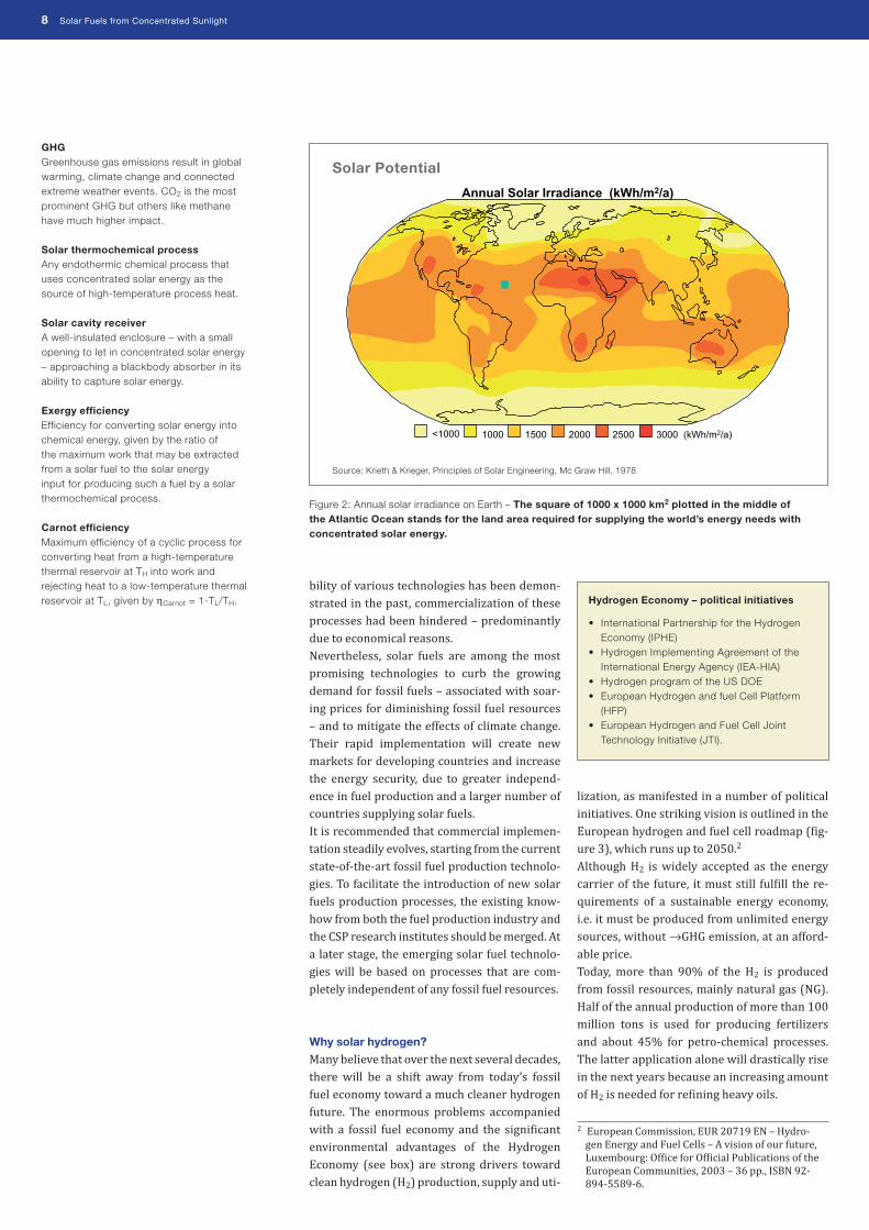
Annual Solar Irradiance (kWh/m2/a)
<1000 1000 1500 2000 2500 3000 (kWh/m2/a)
Figure 2: Annual solar irradiance on Earth – The square of 1000 x 1000 km2 plotted in the middle of the Atlantic Ocean stands for the land area required for supplying the world’s energy needs with concentrated solar energy.
Solar Potential
Source: Krieth & Krieger, Principles of Solar Engineering, Mc Graw Hill, 1978
Hydrogen Economy – political initiatives
• International Partnership for the Hydrogen Economy (IPHE)
• Hydrogen Implementing Agreement of the International Energy Agency (IEA-HIA)
• Hydrogen program of the US DOE• European Hydrogen and fuel Cell Platform
(HFP)• European Hydrogen and Fuel Cell Joint
Technology Initiative (JTI).
Solar Fuels from Concentrated Sunlight 9
These demands can potentially be ful�illed by high temperature processes, which are able to provide large amounts of H2 in centralized plants. Many think that H2 produced using solar energy will provide the long-term solution for solar energy storage. In fact, if H2 is generated from solar energy, it is a completely clean tech-nology; no hazardous wastes or climate chang-ing byproducts are formed and only sunshine and water are required. A lot of research is currently being undertaken around the world, because solar H2 seems to have the highest technical and economical po-tential for successful market introduction. How-ever, since other technologies for energy storage are available – such as carbon dioxide (CO2) or metal oxides – the pros and cons of all of those alternatives should be carefully evaluated.
Solar fuels production
The conversion of solar energy into solar fuels opens up numerous possibilities. There are ba-sically three routes that can be used alone or in combination for producing storable and trans-portable fuels from solar energy: • Electrochemical: solar electricity made from
photovoltaic or concentrating solar thermal systems followed by an electrolytic process;
• Photochemical/Photobiological: direct use of solar photon energy for photochemical and photobiological processes;
• Thermochemical: solar heat at high temper-atures followed by an endothermic →ther-mochemical process.
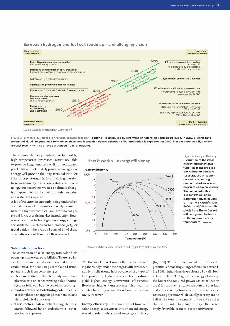
The thermochemical route offers some intrigu-ing thermodynamic advantages with direct eco-nomic implications. Irrespective of the type of fuel produced, higher reaction temperatures yield higher energy conversion ef�iciencies. However, higher temperatures also lead to greater losses by re-radiation from the →solar cavity-receiver.
Exergy ef�iciency – The measure of how well solar energy is converted into chemical energy stored in solar fuels is called →exergy ef�iciency
(�igure 4). The thermochemical route offers the potential of reaching exergy ef�iciencies exceed-ing 50%, higher than those obtained by all alter-native routes. The higher the exergy ef�iciency, the lower the required power (solar collection area) for producing a given amount of solar fuel and, consequently, lower costs for the solar con-centrating system, which usually correspond to half of the total investments of the entire solar chemical plant. Thus, high exergy ef�iciencies imply favorable economic competitiveness.
0
0.1
0.2
0.3
0.4
0.5
0.6
0.7
0.8
0.9
1
0 500 Temperature [K]
1000 1500 2000 2500 3000 3500 4000
Carnot T optimum
1000 5000
10000
20000
40000
E xergy Efficiency 100%
50%
0%
Figure 3: From fossil fuel-based to hydrogen-oriented economy – Today, H2 is produced by reforming of natural gas and electrolysis. In 2020, a significant amount of H2 will be produced from renewables, and increasing decarbonization of H2 production is expected for 2040. In a decarbonized H2 society around 2050, H2 will be directly produced from renewables.
Figure 4: Exergy efficiency – Variation of the ideal exergy efficiency as a function of the process operating temperature for a blackbody cavity-receiver converting concentrated solar en-ergy into chemical energy. The mean solar flux concentration is the parameter (given in units of 1 sun = 1 kW/m2): 1000; 5000; …; 40,000 suns. Also plotted are the →Carnot efficiency and the locus of the optimum cavity temperature Toptimum.
European hydrogen and fuel cell roadmap – a challenging vision
Source: Adapted from European Commission2
How it works – exergy efficiency
Source: Fletcher & Moen, Hydrogen and Oxygen from Water, Science, 1977
2000 Public incentive and private effort
Hydrogen (H2) and Fuel Cell (F
C) fundamental
and applied research; demonstration
RTD, field test, n
iche fleets
Direct H2 production from renewablesDe-carbonized H2 society
H2 production& distribution
Hydrogen-oriented economy
Fossil fuel-based economy
FC & H2 systems development & deployment
FC vehicles series production for fleets
Stationary low-temperature FC systems (PEM; < 300 kW)
Stationary high-temperature FC systems (MCFC/SOFC; < 500 kW)
FC vehicles competitive for passenger cars
Atmospheric and hybrid SOFC systemscommercial (< 10 MW)
FC become dominant technology in transport,
in distributed power generation, and in micro-applications
H2 prime fuel choice for FC vehicles
Increasing decarbonization of H2 production Renewables, fossil fuel with sequestration, new nuclear
Significant H2 production from renewables
H2 produced from fossil fuels with C sequestration
H2 production by reforming and electrolysis at local refueling station
H2 produced by NG reforming and electrolysis
Widespread H2 pipeline infrastructure
Public reward and private benefits
Hydrogen and Fuel Cell large-scale
commercialization
Increasing market penetration
2010
2020
2030
2040
2050

10 Solar Fuels from Concentrated Sunlight
Solar tower facilities
The state-of-the-art solar concentrating tech-nology for large-scale solar energy collection at high →solar concentration ratio is based on the solar tower optical con�iguration using a �ield of heliostats (two-axis tracking parabolic or �lat mirrors) that focus the sun rays onto a solar receiver mounted on top of a centrally located
tower. Solar tower systems (�igure 5) – also re-ferred to as central receiver systems – may have either a circular �ield of heliostats with a can-tered receiver on top of the tower, as in the case of (a) the Solar Two power plant at Barstow, USA, or an asymmetric �ield, like the south fac-ing test facilites at (b) the Plataforma Solar de Almería (PSA), Spain, and (c) Targassonne,
In Focus – Solar Concentrating Technologies
Solar concentration ratio Non-dimensional ratio of the solar flux intensity – e.g., given in “suns” (1 sun = 1 kW/m2) – achieved after concentration to the normal insolation of incident beam.
Solar tower facilities – state of the art
Figure 5: Solar towers – Examples of concentrating solar research facilities based on the tower concept.
(a) 60 MWth solar tower, Barstow, USA (Solar Two)
(d) 500 kWth solar tower, CSIRO, Newcastle, Australia
(b) 7 MWth solar tower, PSA, Almería, Spain (CESA 1)
(e) 3 MWth solar tower with “beam down” optics, WIS, Rehovot, Israel
(c) 4.5 MWth solar tower, Targassonne, France (THEMIS)

Solar Fuels from Concentrated Sunlight 11

12 Solar Fuels from Concentrated Sunlight
France, or (d) CSIRO’s north facing test facility in Newcastle, Australia. A novel optical con�igu-ration – called “beam-down” – developed at (e) WIS in Israel for the tower system makes use of a hyperboloidal re�lector at the top of the tower to re-direct sunlight to a secondary concentrator and a receiver-reactor located at ground level.
Secondary concentrators – The solar �lux con-centration ratio typically obtained by solar tower systems is between 1000–1500 suns (1 sun = 1 kW/m2). In principle, such concentrating so-lar devices can reach temperatures exceeding 1700°C, with optimal cavity temperatures of around 1000°C (�igure 4). To some extent, the �lux concentration can be further augmented with the help of a secondary concentrator (�igure 6), such as a compound parabolic concentrator (→CPC), which is positioned in tandem with the primary parabolic concentrating system. Higher �lux concentrations have the advantage of lower heat losses from smaller aperture areas and high-er attainable temperatures in the cavity receiver. The disadvantage of such solar concentrating op-
tics is that their smaller acceptance angle – which requires a longer and less ef�icient heliostat �ield – results in optimum temperatures closer to 1000°C rather than to 2000°C for ef�iciently op-erating a solar tower system on an annual basis.The solar concentrating systems have proven to be technically feasible in large-scale pilot and commercial plants aimed at producing elec-tricity (�igure 7). They make use of a working �luid (typically air, water, synthetic oil, helium, sodium, or molten salt) that is heated by solar energy and then used in traditional steam or gas turbines. The typical land area required for a 50 MWth solar tower plant is about 300,000 m2, with a land use factor of 0.25 (fraction of re�lec-tive mirror area).Solar thermochemical applications, although not as far advanced as solar thermal electricity generation, employ the same solar concentrat-ing technologies. However, the heliostat �ield layout may look different since high-temper-ature thermochemical processes require a higher performance in solar concentration than solar thermal power plants. This also has an im-pact on investment costs for the concentrating solar facilities and their operational strategies.
Concentrating solar research facilities
All over the world, research groups are develop-ing the scienti�ic and engineering know-how for large scale production of solar fuels, in particu-lar solar hydrogen. For these state-of-the-art R&D efforts, dedicated concentrating research facilities – solar furnaces and solar simulators – are employed (�igure 8).
Solar furnace – Solar furnaces receive the solar radiation by one or more heliostats like solar towers. But instead of a tower with a central re-
CPC Compound Parabolic Concentrator, a secondary optical element intended to augment the concentration of incoming solar radiation, e.g. on top of a solar tower facility.
Solar furnace Two main configurations are used: (a) On-axis: heliostat, parabolic concen-
trator, and experimental platform are positioned in one line.
(b) Off-axis: facetted mirrors with varying focal lengths reflect the solar radiation to the side, where the solar receiver-reactor is mounted in the focal plane.
HFSS High-Flux Solar Simulators (HFSS) in operation: (a) 150 kWel HFSS consisting of 10 Xenon
arc lamps with common focus at Paul Scherrer Institute (PSI), Villigen, Switzerland.
(b) 60 kWel HFSS using 10 IR radiators at German Aerospace Center (DLR), Cologne, Germany.
Figure 7: Commercial electricity production using so-lar tower concept – The 11 MWel PS10 plant (back) is in operation since 2007, and the 20 MWel PS20 plant (front) is in operation since 2009, both at Sanlúcar La Mayor near Seville, Spain.
First commercial solar tower power plants
Source: Abengoa Solar
Figure 6: CPC – a) Multiple CPC mounted in front of a solar receiver on the CESA 1 solar tower at PSA, Spain; b) CPC for “beam down” application at WIS, Israel.
Secondary concentrator (CPC)
a Source: DLR
b Source: WIS

Solar Fuels from Concentrated Sunlight 13
20 kWth HFSS at DLR, Cologne (D) 50 kWth HFSS at PSI, Villigen (CH)
25 kWth off-axis solar furnace at DLR, Cologne (D)
40 kWth on-axis solar furnace at PSI, Villigen (CH)
25 kWth off-axis solar furnace at NREL, Golden, CO (USA)
60 kWth on-axis solar furnace at Plataforma Solar de Almería (E)
1 MWth solar furnace at CNRS-PROMES, Odeillo (F)
1 MWth solar furnace at Parkent (Uzbekistan)
3 MWth solar tower with “beam down” optics at WIS, Rehovot (IL)
16 kWth on-axis solar furnace at Sandia, Albuquerque, NM (USA)
500 kWth solar tower at CSIRO, Newcastle (AUS)
40 kWth on-axis solar furnace at KIER, Daejeon (KOR)
Figure 8: Concentrating solar research facilities – High-flux solar furnaces (HFSF) and simulators (HFSS), and solar towers.
Solar research infrastructure worldwide – state of the art

14 Solar Fuels from Concentrated Sunlight
ceiver, a parabolic mirror is used as a secondary optical component to concentrate the sunlight up to 20,000 times. The parabolic mirror may be facetted because single mirrors are restrict-ed in their size. The largest solar furnaces in Odeillo, France, and Parkent, Uzbekistan, have a thermal power of 1 MW and a size equivalent to a 12-story building. The standard geometrical con�iguration of a →solar furnace consists of a heliostat, parabolic concentrator, and experi-mental platform in one line and, therefore, is called ‘on-axis’ (�igure 9). Usually, the reactor is mounted on a platform and then raised up to the focus of the parabolic mirror, thereby, shadowing part of the concentrator. To avoid shadowing of the concentrator, facetted mirrors with varying focal lengths can be used to re�lect the solar radiation to the side. This so-called
‘off-axis’ concept has the advantage of easier operation but is more complex and, therefore, more expensive.
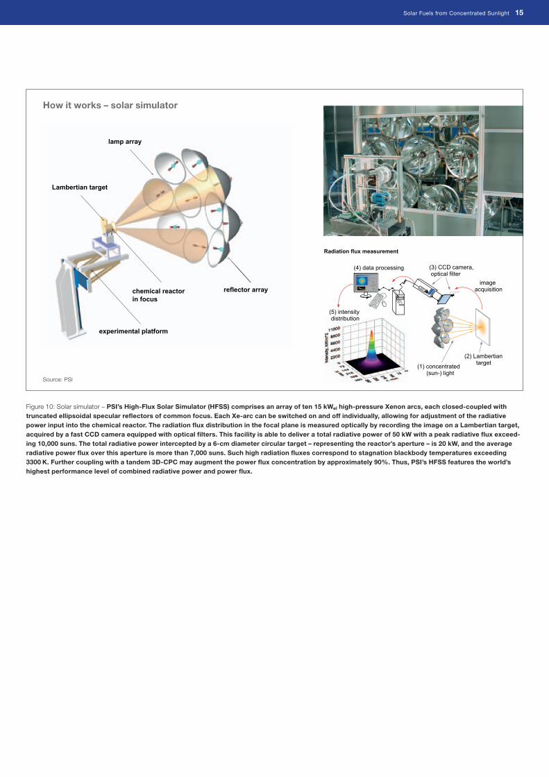
Solar simulator – In contrast to solar furnaces, which depend on varying weather conditions and deal with problems of intermittent so-lar irradiation and a moving radiation source, high-�lux solar simulators (→HFSS) offer more stable and reproducible operating conditions (�igure 10). Experiments requiring long dura-tions can be performed easily without the prob-lem of daytime-only operation. For ef�icient de-velopment of solar fuel production processes, however, both concentrating research facilities are extremely important and, because of their different characteristics, neither one can be substituted for the other.
Figure 9: Solar furnace – PSI’s High-Flux Solar Furnace (HFSF) consists of a 120 m² sun-tracking fl at heliostat on-axis with an 8.5 m-diameter paraboloidal con-centrator. It delivers up to 40 kW at peak concentration ratios exceeding 5000 suns. The solar fl ux intensity can be further augmented to up to 10,000 suns by using CPC secondary concentrators. A Venetian blind type shutter located between the heliostat and the concentrator controls the power input to the reactor.
How it works – solar furnace
Source: PSI
Radiation flux measurement
(2) Lambertian
target (1) concentrated
(sun-) light
(3) CCD camera, optical filter
IO
(4) data processing
image acquisition
(5) intensity distribution
Radiation flux measurement
(2) Lambertian
target (1) concentrated
(sun-) light
(3) CCD camera, optical filter
IO
(4) data processing
image acquisition
(5) intensity distribution
Solar Fuels from Concentrated Sunlight 15
Figure 10: Solar simulator – PSI’s High-Flux Solar Simulator (HFSS) comprises an array of ten 15 kWel high-pressure Xenon arcs, each closed-coupled with truncated ellipsoidal specular refl ectors of common focus. Each Xe-arc can be switched on and off individually, allowing for adjustment of the radiative power input into the chemical reactor. The radiation fl ux distribution in the focal plane is measured optically by recording the image on a Lambertian target, acquired by a fast CCD camera equipped with optical fi lters. This facility is able to deliver a total radiative power of 50 kW with a peak radiative fl ux exceed-ing 10,000 suns. The total radiative power intercepted by a 6-cm diameter circular target – representing the reactor’s aperture – is 20 kW, and the average radiative power fl ux over this aperture is more than 7,000 suns. Such high radiation fl uxes correspond to stagnation blackbody temperatures exceeding 3300 K. Further coupling with a tandem 3D-CPC may augment the power fl ux concentration by approximately 90%. Thus, PSI’s HFSS features the world’s highest performance level of combined radiative power and power fl ux.
How it works – solar simulator
Source: PSI
lamp array
chemical reactor
in focus
reflector array
experimental platform
Lambertian target

16 Solar Fuels from Concentrated Sunlight
Hydrogen is envisioned as a future energy carri-er. The production routes require chemical and energy sources that are truly sustainable only if they offer closed material cycles that do not produce CO2. Clean H2 production from water (H2O) and energy from renewable sources will become the paradigm of the hydrogen economy concept. Replacing fossil fuels with renewable energy will shift the balance between electricity and fuels. For many applications, electricity will be used instead of fuels, but two major applica-tions will require a massive production of solar H2. Firstly, renewable energy must be stored for balanced use, and, secondly, mobility will prob-ably be based on fuels rather than electricity. Therefore even in rather conservative studies, the drastic increase in demand for electricity will be coupled with a rising demand for H2. This development is starting slowly now, but various scenarios indicate that H2 will become more important after 2030. The WETO-H2 sce-nario predicts a H2 demand equivalent to about 1 billion tons of oil in 2050 (�igure 11).
Solar production of hydrogen
Solar electricity – generated via photovoltaics (PV) or concentrating thermal power (CSP) – followed by →electrolysis of water, is a vi-able technical route for producing H2. Today, it can be considered as a benchmark for other routes such as solar-driven water-splitting thermochemical cycles that offer the potential of energy ef�icient large-scale production of H2 (�igure 12). With solar electricity from PV and solar thermal at ef�iciencies of around 15%
and1 20%, respectively, and →electrolyzers at 80% ef�iciency, the overall solar-to-hydrogen energy conversion ef�iciency ranges between 12% and 16%. Projected costs of H2, assuming solar thermal electricity costs of 0.08 $/kWhel, range from 0.15–0.20 $/kWh (→LHV of H2), i.e. from 6–8 $/kg H2. For PV electricity, costs are expected to be twice as high. The electric-ity demand for electrolysis can be signi�icantly reduced if the electrolysis of water proceeds at
1 World Energy Technology Outlook – 2050, Luxembourg: Of�ice for Of�icial Publications of the European Communities, 2006, ISBN 92-79-01636-9, online: http://ec.europa.eu/research/energy/pdf/weto-h2_en.pdf
Solar Hydrogen – Future Energy Carrier
Electrolysis of water Decomposition of water (H2O) into oxygen (O2) and hydrogen gas (H2) due to an electric current being passed through the water.
Electrolyzer An apparatus to separate chemically bonded elements and compounds by passing an electric current through them.
LHV The lower heating value of a fuel is defined as the amount of heat released by combusting a specified quantity (initially at 25°C) and returning the temperature of the combustion products to 150°C, which assumes the latent heat of vaporization of water in the reaction products is not recovered.
Figure 11: Global energy carrier demand – The WETO (World Energy Technology Outlook) study1 by the European Union is a projection of the world energy system in 2050 with emphasis on the hydrogen economy. After 2030, the increasing demand for electricity will be coupled with a rising demand for H2.
5000Coal, LigniteOilGasElectricityHydrogen
Mill
ion
To
ns
Oil
Eq
uiv
alen
t (m
toe)
4500
4000
3500
3000
2500
2000
1500
1000
500
01990 2001 2010 2020 2030 2050
Hydrogen – future energy carrier
Source: WETO-H2, 2006

Solar Fuels from Concentrated Sunlight 17

18 Solar Fuels from Concentrated Sunlight
higher temperatures (800–1000°C) via Solid Oxide Electrolyzer Cells (→SOEC). Concentrat-ed solar energy can be applied to provide the high-temperature process heat.
H2 from H2O by solar thermolysis
The single-step thermal dissociation of H2O to H2 and O2 is known as water thermolysis. Al-though conceptually simple, its realization is very challenging since it needs a high-temper-ature heat source above 2200°C for achieving a reasonable degree of dissociation, and an ef-fective technique for separating H2 and O2 to avoid an explosive mixture. Among the ideas proposed for separating H2 from the products are →effusion separation and electrolytic sepa-ration. Membranes based on ceramics like zir-conia and other high-temperature materials have been tested above this temperature, but they usually fail to withstand the severe ther-mal shocks that often occur when working un-der high-�lux solar irradiation. Rapid →quench by injecting a cold gas, expan-sion in a nozzle, or submerging a solar-irradiat-ed target in liquid water, is simple and workable, but the quench introduces a signi�icant drop in the exergy ef�iciency and produces an explosive gas mixture. Furthermore, the very high temper-
atures required by the thermodynamics of the process (e.g. 2725°C for 64% dissociation at at-mospheric pressure) pose severe material limi-tations and can lead to signi�icant re-radiation from the reactor, thereby lowering the ef�iciency.
H2 from H2O by solar thermochemical cycles
Water-splitting thermochemical cycles by-pass the separation problem and further allow operation at moderately high temperatures. Previous studies performed on thermochemi-cal cycles were mostly characterized by using process heat at temperatures below 950°C, which are expected to be available in the future from very high temperature nuclear reactors (→VHTR). These cycles required three or more chemical reaction steps (two steps in the case of the hybrid sulfuric acid cycle incorporating one electrolysis step) and are challenging because of material problems and inherent inef�icien-cies associated with heat transfer and product separation at each step. The leading candidates for multi-step thermochemical cycles include mainly a three-step →sulfur iodine cycle based on the thermal decomposition of sulfuric acid at 850°C and a four-step →UT-3 cycle based on the hydrolysis of calcium and iron bromide at 750°C and 600°C, respectively.
SOEC A Solid Oxide Electrolyzer Cell is able to split water at high temperatures up to 900°C with a higher efficiency than conventional steam (alkaline) electrolysis near room temperature. This technology currently under development is one promising candidate for efficient high temperature hydrogen production.
Effusion Flow of gas through an orifice whose diameter is small as compared with the distance between molecules of the gas.
Quench Rapid cooling – for example used as gas separation technique to prevent recombination of product gases.
VHTR The Very High Temperature Reactor is one of six designs under discussion for the next generation of nuclear reactors. Recently, a pebble bed nuclear reactor was demonstrated at the research center Jülich, Germany.
Sulfur-iodine cycle 3-step cycle based on the thermal decom-position of sulfuric acid (H2SO4) at 850°C. Mainly developed by General Atomics (GA) and demonstrated as an electrically heated laboratory plant at Japan Atomic Energy Agency in 2004.
UT-3 cycle 4-step cycle based on the hydrolysis of cal-cium and iron bromide (CaBr2 and FeBr2) at 750°C and 600°C, respectively. University of Tokyo (UT), Japan.
Redox reaction Reduction/oxidation reactions describe all chemical reactions in which atoms have their oxidation number (oxidation state) changed.
Aerosol-flow reactor The aerosol flow reactor method is a simple and efficient one-step process that can directly produce particles within a desirable particle size range with consistent and controlled properties.
Decarbonization H2O-splitting
Solar Fuels (Hydrogen, Syngas)
Solar
Cracking
Solar
Gasification
Solar
Reforming
Solar
Thermolysis
Solar
Thermochemical
Cycle
Solar
Electricity
+ Electrolysis
Concentrated
Solar Energy
Fossil Fuels (NG, oil, coal)
Optional CO2/C Sequestration
H2O
Figure 12: Thermochemical routes for solar hydrogen production – Indicated is the chemical source of H2: H2O for the solar thermolysis and the solar thermochemical cycles; fossil fuels for the solar cracking, and a combination of fossil fuels and H2O for the solar reforming and solar gasification. For the solar decarbonization processes, optional CO2/C sequestration is considered. All of those routes involve energy consuming (endothermic) reactions that make use of concentrated solar radiation as the energy source of high-temperature process heat.
How it works – thermochemical routes for the production of solar fuels (H2, syngas)
Source: PSI

rotary joint ceramic
insulation
quartz window
cavity - receiver
water/gas inlets/outlets feeder
Zn + ½ O 2
ZnO
rotary joint ceramic
insulation
quartz window
cavity - receiver
water/gas inlets/outlets feeder
Zn + ½ O 2
ZnO
Zn + ½ O 2
ZnO
concentrated solar
radiation
Solar Fuels from Concentrated Sunlight 19
In recent years, signi�icant progress has been made in the development of optical systems for large-scale solar concentrators capable of achieving mean solar concentration ratios that exceed 5,000 suns. Such high radiation �luxes allow temperatures above 1200°C, which are needed for the more ef�icient two-step thermo-chemical cycles using metal oxide →redox reac-tions (�igure 13).
Zn/ZnO cycle – One of the most researched metal oxide redox pairs for the two-step cycle is based on zinc (Zn) and zinc oxide (ZnO). Since the products of the solar high temperature ZnO decomposition – gaseous Zn and oxygen (O2) – rapidly recombine, a quenching process is nec-essary. The estimated exergy ef�iciency of this cycle is 35% without heat recovery from the quench process. Alternatively, electro-thermal methods for in-situ separation of gaseous Zn and O2 at high temperatures have been experi-mentally demonstrated in small-scale reactors. High-temperature separation further enables recovery of the sensible and latent heats of the products to enhance the ef�iciency. A high-tem-perature solar chemical reactor concept was de-veloped for this process (�igure 14). Solar tests carried out at PSI’s solar furnace, Switzerland, with a 10 kW reactor prototype subjected to a peak solar concentration of 4000 suns revealed the low thermal inertia of the reactor system – the surface temperature reached 1700°C in two
seconds and was resistant to thermal shocks. In 2010, the solar chemical reactor concept for the thermal dissociation of ZnO will be demon-strated in a 100 kWth pilot plant at a large solar research facility.For the H2 production step (Zn + H2O → ZnO + H2) laboratory studies and preliminary tests with a novel concept of a hydrolyser (hydrolysis reactor) indicate that the water-splitting reac-tion works at reasonable rates above 425°C. This was experimentally demonstrated using a so-called →aerosol-�low reactor for in-situ for-mation and hydrolysis of Zn nano-particles. In principle, the heat liberated by the exothermic reaction could be used to melt Zn and produce steam. Alternatively, if the H2 production plant was located next to the solar plant, molten Zn from the quencher unit at 425°C (or higher) could be fed directly to the hydrolyser. On the other hand, transportation of solid Zn to the site where H2 is �inally used eliminates the need for storage and transportation of H2. Another pos-
sible application of this cycle is to use the energy carrier Zn directly in Zn-air batteries. This tech-nology is already commercially available, and some companies are pursuing a fuel-cell ana-logue with ‘mechanically-rechargeable’ Zn-air batteries for stationary or mobile applications.
SnO/SnO2 cycle – Another promising metal oxide cycle is based on tin oxide (redox pair SnO/SnO2). Exergy and energy ef�iciencies of this redox pair are 30% and 36% respectively. Atmospheric and reduced pressure experi-ments showed that the SnO2 reduction can be performed ef�iciently at 1500°C and the SnO hydrolysis at 550°C. A 1 kW solar reactor pro-totype was successfully tested for continuous operation at Odeillo, France (�igure 15).
Mixed iron oxide cycle – Other metal ox-ides such as manganese oxide or cobalt oxide, as well as mixed oxides redox pairs – mainly based on iron – have also been considered. The
Figure 13: Thermochemical route based on metal oxide redox reactions – The first step of the cycle is the solar thermal release of O2 from the metal oxide (MxOy). This step requires very high temperatures. The second step is the reaction of the metal (M) with H2O to form H2 and the cor-responding MxOy. This step proceeds at lower temperatures and does not require additional heating in some cases. Since H2 and O2 are formed in different steps, the need for high-tem-perature gas separation is thereby eliminated. This cycle was originally proposed for an iron oxide redox system.
H2
H2O
½ O2
recycle
HYDROLYSIS
REACTOR
xM + yH2O = MxOy + yH2
SOLAR
REACTOR
MxOy = xM + y/2 O2
MxOy
M
MxOy
Concentrated
Solar Energy
How it works – metal oxide cycles
Source: PSI
Rotary solar cavity reactor
Source: PSI
Figure 14: Rotary solar reactor for the thermal dissociation of zinc oxide to zinc and oxygen at above 1700°C – The concept features a windowed rotating cavity-receiver lined with ZnO particles that are held by centrifugal force. With this arrange-ment, ZnO is directly exposed to high-flux solar irradiation and serves simultaneously the functions of radi-ant absorber, thermal insulator, and chemical reactant.
Figure 15: Lab-scale solar reactor for the reduction of tin oxide (SnO2) at 1500°C – The rotary reactor can operate continuously by particle injection and at reduced nitrogen pressure in order to decrease thedecomposition temperature.
Rotary solar reactor
Source: CNRS-PROMES

20 Solar Fuels from Concentrated Sunlight
mixed iron oxide cycle was demonstrated at the 10 kWth level within the EU’s R&D project HYDROSOL (2002–2005). The model for the monolithic solar thermochemical reactor (�ig-ure 16) was the catalytic converter used for exhaust treatment in automobiles. The reactor contains no moving parts and is constructed from ceramic multi-channeled monoliths that absorb the solar radiation. The monolith chan-nels are coated with mixed iron oxide →nano-materials, which are activated by heating to 1250°C. After releasing the O2, they are capable of splitting water vapor passing through the reactor by trapping the O2 and leaving H2 as the product in the ef�luent gas stream at 800°C. Thus, no explosive gas mixtures are produced. Cyclic operation is established on a single, closed receiver-reactor system. A quasi-contin-uous H2 �low is produced by alternate operation of two or more reaction chambers.
Continuation within the EU’s award-winning P&D project HYDROSOL 2 (2005-2009) is di-rected at testing a 100 kWth dual chamber pi-lot reactor at the Plataforma Solar de Almería (PSA), Spain.
Carbothermal reduction of metal oxides – The carbothermal reduction of metal ox-ides using coke, natural gas (NG), and other carbonaceous materials as →reducing agents brings about reduction of the oxides at even lower temperatures. Carbothermal reductions of metal oxides like iron oxide, manganese ox-ide, and zinc oxide with carbon and natural gas to produce the metals and →syngas have been demonstrated in solar furnaces. Such a solar chemical reactor concept – PSI’s ‘two-cavity’ solar reactor (�igure 17) based on the indirect irradiation of ZnO and carbon (C) for producing Zn and carbon monoxide (CO) – was scaled up
Nano-material Consists of nano-sized particles hav-ing diameters of less than 1 microm-eter.
Reducing agent Donates electrons to a chemical com-pound, e.g. de-oxidizes a metal.
Syngas Synthesis gas is a mixture of H2 and CO produced by reacting natural gas with steam at 850°C and high pressure. The name comes from its role as an important starting substance for chemical synthesis.
Sequestration Term mainly used for permanent storage of CO2, either in gaseous form in deep geological formations, in liquid form in the ocean, or in solid form in mineral carbon-ates.
Fischer-Tropsch A process developed in 1925 by Franz Fischer and Hans Tropsch to convert syn-gas into liquid hydrocarbons, e.g. fuels like gasoline or diesel.
Watergas shift reaction Chemical reaction in which CO reacts with water to form CO2 and H2.
Pressure swing adsorption Technology used to separate some gas species from a mixture of gases under pressure at near-ambient tempera-tures.
quartz
window
upper cavity
(absorber)
lower cavity
(reaction chamber)
ZnO/C
packed - bed
carrier gas
inlet
300 kW
concentrated solar
power
gaseous
products
Two-cavity solar reactor
Source: PSI
Figure 17: Two-cavity solar reactor concept for the carbo-thermal reduction of ZnO – The upper cavity (absorber) serves as the solar receiver and radiant emitter. The lower cavity is a well-insu-lated enclosure containing a ZnO/C packed bed. It serves as the reaction chamber and is subjected to thermal radiation from the upper cavity. With this arrange-ment, the upper cavity protects the quartz window against particles and con-densable gases coming from the reaction chamber.
Figure 16: Monolithic dual chamber solar receiver-reactor for continuous H2 production – The concept features a closed receiver-reactor constructed from ceramic multi-channeled monoliths (left). Cyclic operation of the water-splitting and regeneration steps is established in two reaction chambers. Their individual temperature levels are controlled by focusing and defocusing heliostats during thermal tests at PSA, Spain (right).
double tube
for feed gas
preheating
four-way
valve
four-way
valve to mass
spectrometer
ducts for feed
gases inlet for feed
gases
cylindrical
SiC housing
coated honeycomb structure
quartz windows
sealing
steam N2
H2
steam
N2 (O2)
Monolithic solar reactor
Source: DLR

Solar Fuels from Concentrated Sunlight 21
within the EU’s R&D project SOL ZINC (2001–2005). Testing of the 300 kWth solar chemical reactor (�igure 18) at the solar tower research facility of WIS, in Israel, at temperatures rang-ing from 1000–1200°C yielded up to 50 kg/h of 95%-purity Zn and an energy conversion ef�iciency of around 30%. The SOLZINC proc-ess provides an ef�icient thermochemical route for storing and transporting solar energy. The
process can be CO2-neutral if charcoal is used for reducing ZnO.
H2 by decarbonization of fossil fuels
Three solar thermochemical processes for H2 production using fossil fuels as the chemical source are considered: cracking, reforming, and gasi�ication (�igure 19). The solar cracking route refers to the thermal decomposition of NG, oil, and other hydrocarbon into H2 and car-bon. The carbonaceous solid product can either be →sequestered (see box) without CO2 release or used as material commodity or reducing agent under less severe CO2 restraints.Steam-reforming of NG, oil, and other hydrocar-bons, and steam-gasi�ication of coal and other solid carbonaceous materials yield syngas, the building block for a wide variety of synthetic fuels including →Fischer-Tropsch type chemi-cals, H2, ammonia, and methanol. The quality is determined mainly by the ratios between H2, CO, and CO2. The CO content in the syngas can be shifted to H2 via a catalytic reaction with steam – the so called →watergas shift reaction. The product, CO2, can be separated from H2, e.g. by using the →pressure swing adsorption tech-nique.
Solar reforming – Solar reforming of NG, using either steam or CO2, has been extensively stud-ied in solar concentrating facilities with small-scale solar reactor prototypes. The solar re-
forming process developed within the EU’s R&D project SOLREF (2004–2009) has been scaled-up to power levels of 300–500 kWth and tested at 850°C and 8–10 bars in a solar tower using two solar reforming reactor concepts: indirect-irradiation and direct-irradiation (see box). The indirect-irradiated solar reforming reactor (not shown here) consists of a cavity receiver insulated with ceramic �ibers that contains a set of vertical tubes externally exposed to the concentrated solar radiation. A matching CPC is installed at the windowless cavity →aperture for capturing radiation spillage, augmenting the average solar �lux concentration, and providing uniform heating of the tubes. Similar to the indi-rect-irradiated reactor, a CPC is installed at the aperture of the direct-irradiated solar reactor – also referred to as the volumetric solar reactor (�igure 20).
Solar reactor – direct vs. indirect irradiation
Direct-irradiation reactor – Provides efficient ra-diation heat transfer to the reaction site where the energy is needed, by-passing the limitations imposed by indirect heat transport via heat exchangers. The major drawback when work-ing with reducing or inert atmospheres is the requirement for a transparent window, which is a critical and troublesome component in high-pressure and severe gas environments.
Indirect-irradiation reactor – Eliminates the need for a transparent window. The disadvan-tages are linked to the limitations imposed by the materials of construction of the reactor walls: constraints in maximum operating tem-perature, thermal conductivity, radiant absorb-ance, inertness, resistance to thermal shocks, and suitability for transient operation.
Figure 18: 300 kWth solar chemical pilot plant devel-oped and tested in the EU’s R&D project SOLZINC – The two-cavity reactor (1.4 m inner diameter) for the carbothermal reduction of ZnO is specifically designed for beam-down incident radiation, as obtained at the solar tower research facility at WIS, Israel.
Source: PSI
Fossil Fuels (NG, oil)
Solar Cracking Rea c tor
C H 2 Sequestration
Fuel cell
Concentrated Solar Energy
Work Output
O 2
Solar Gas ./Ref. Reactor
CO 2
Concentrated Solar Energy
Fossil Fuels (coal, NG, oil)
H 2 O CO H 2
Shift Reactor
H 2 O
CO 2 H 2 Separation
H 2
Fuel cell Work Output
O 2
Solar Cracking
Reac tor
C H 2
Fuel cell
O 2
Solar Gas ./Ref. Reactor
Concentrated Solar Energy
H 2 O CO H 2
Shift Reactor
H 2 O
2 Separation
H 2
Fuel cell
O 2 Sequestration
How it works – decarbonization processes
Source: PSI
Figure 19: Solar thermochemical routes for H2 pro-duction using fossil fuels and H2O as the chemical source – Solar cracking (top), and solar reforming and gasification (bottom).
How it works – carbon sequestration
From the point of view of carbon sequestration, it is easier to separate, handle, transport, and store solid carbon than gaseous CO2. Further-more, while the steam reforming/gasification method requires additional steps for shifting CO and for separating CO2, the thermal cracking accomplishes the removal and separation of carbon in a single step.
In contrast, the major drawback of the thermal decomposition method is the energy loss associated with the sequestration of carbon. Thus, the solar cracking may be the preferred option for NG and other hydrocarbons with high H2/C ratio. For coal and other solid carbona-ceous materials, the solar gasification has the additional benefit of converting a solid fuel traditionally used for combustion to generate electricity into a cleaner fluid fuel – cleaner only when using solar process heat – that can be used in highly efficient fuel cells.
For the solar NG cracking and the solar coal gasification without CO2 sequestration, specific CO2 emissions amount to 0.53-0.56 kg CO2/kWhel, about half as much as the specific emis-sions discharged by conventional coal-fired power plants.
Catalytic absorber
WindowCPC Reactants inlet
Products outlet
Volumetric solar reactor
Source: DLR
Figure 20: Volumetric solar reactor concept for the reforming of NG – The main component is the porous ceramic absorber, coated with Rhodium catalyst, which is directly exposed to the concentrated solar radiation. A concave quartz window, mounted at the aperture, minimizes reflection losses and permits operation at elevated pressures.
ceramic cavity
concentrated
solar
radiation
quartz window
syngas
(H 2 + CO)
petcoke + H2O slurry
H2O nozzle
vortex flow
22 Solar Fuels from Concentrated Sunlight
Dry reforming of methane (CH4) with CO2 was performed in an aerosol solar reactor similar to the one used for NG cracking (see �igure 24 below). Operating with residence times around 10 milliseconds and temperatures of approxi-mately 1700°C, methane and CO2 conversions of 70% and 65%, respectively, were achieved in the absence of →catalysts.The solar dry reforming of CH4 with CO2 can also be used in a closed-loop chemical heat pipe (�igure 21). The product of this reversible reac-tion is syngas which can be stored at ambient temperatures and transported to sites requir-ing energy. Stored solar energy is released by the reverse exothermic reaction in the form of heat, which can be used for generating electric-ity via a →Rankine cycle. The products of this reverse reaction are again recycled to the solar reactor to complete the cycle. Similarly, the dissociation/synthesis of ammo-nia (NH3) can be applied in a chemical heat pipe for storage and transportation of solar energy. In this system developed by the Australian Na-tional University (ANU), ammonia is dissociat-ed in an energy storing (endothermic) chemical reactor as it absorbs solar thermal energy. At a
later time and place, the reaction products of H2 and nitrogen (N2) react in an energy releas-ing (exothermic) reaction to re-synthesize am-monia. An industrial demonstration plant has been announced using four of ANU’s 400 m2 →parabolic dishes.
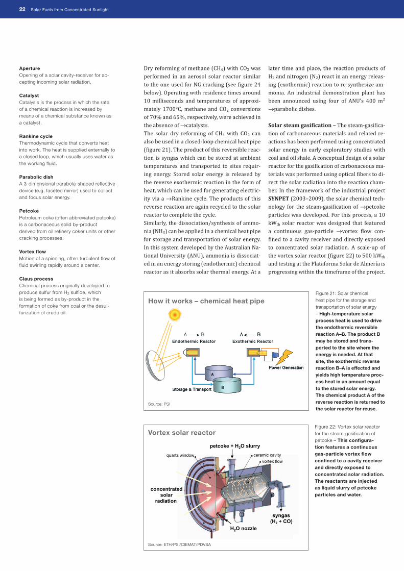
Solar steam gasi�ication – The steam-gasi�ica-tion of carbonaceous materials and related re-actions has been performed using concentrated solar energy in early exploratory studies with coal and oil shale. A conceptual design of a solar reactor for the gasi�ication of carbonaceous ma-terials was performed using optical �ibers to di-rect the solar radiation into the reaction cham-ber. In the framework of the industrial project SYNPET (2003–2009), the solar chemical tech-nology for the steam-gasi�ication of →petcoke particles was developed. For this process, a 10 kWth solar reactor was designed that featured a continuous gas-particle →vortex �low con-�ined to a cavity receiver and directly exposed to concentrated solar radiation. A scale-up of the vortex solar reactor (�igure 22) to 500 kWth and testing at the Plataforma Solar de Almería is progressing within the timeframe of the project.
Aperture Opening of a solar cavity-receiver for ac-cepting incoming solar radiation.
Catalyst Catalysis is the process in which the rate of a chemical reaction is increased by means of a chemical substance known as a catalyst.
Rankine cycle Thermodynamic cycle that converts heat into work. The heat is supplied externally to a closed loop, which usually uses water as the working fluid.
Parabolic dish A 3-dimensional parabola-shaped reflective device (e.g. faceted mirror) used to collect and focus solar energy.
Petcoke Petroleum coke (often abbreviated petcoke) is a carbonaceous solid by-product derived from oil refinery coker units or other cracking processes.
Vortex flow Motion of a spinning, often turbulent flow of fluid swirling rapidly around a center.
Claus process Chemical process originally developed to produce sulfur from H2 sulfide, which is being formed as by-product in the formation of coke from coal or the desul-furization of crude oil.
Vortex solar reactor
Source: ETH/PSI/CIEMAT/PDVSA
Figure 22: Vortex solar reactor for the steam-gasification of petcoke – This configura-tion features a continuous gas-particle vortex flow confined to a cavity receiver and directly exposed to concentrated solar radiation. The reactants are injected as liquid slurry of petcoke particles and water.
How it works – chemical heat pipe
Source: PSI
Figure 21: Solar chemical heat pipe for the storage and transportation of solar energy – High-temperature solar process heat is used to drive the endothermic reversible reaction A–B. The product B may be stored and trans-ported to the site where the energy is needed. At that site, the exothermic reverse reaction B–A is effected and yields high temperature proc-ess heat in an amount equal to the stored solar energy. The chemical product A of the reverse reaction is returned to the solar reactor for reuse.

Solar Fuels from Concentrated Sunlight 23
Solar cracking – Cracking of CH4 or NG is a nonconventional route for potentially cost-ef-fective H2 production and carbon nano-mate-rial synthesis with concentrated solar energy. The process thermally decomposes NG in a high temperature solar chemical reactor, yield-ing two valuable products: a H2-rich gas and a marketable high-value nano-material called ‘Carbon Black’ (CB). Thus, both H2 and CB are produced by renewable energy, resulting in po-tential CO2 emission reduction of 14 kg of CO2 and energy saving of 277 MJ per kg H2 com-pared to conventional NG steam reforming and standard CB processing. A novel 10 kWth tubular solar reactor (�igure 23) was successfully tested at a temperature range of 1430–1800°C at the solar furnace of CNRS-PROMES in Odeillo, France. A high dissociation of 98% was achieved with a 90% H2 yield. An advanced 50 kWth solar reactor prototype is being developed in the framework of the EU’s R&D project SOLHYCARB (2006–2010). Also, a tubular aerosol reactor (�igure 24) was tested at NREL in Golden, Colorado, where methane conversion of up to 90% was obtained. Fur-ther studies are being performed at ETH Zurich, Switzerland, in a so-called vortex solar reactor con�iguration (�igure 22), which was tested in a methane �low laden with carbon particles that
serve simultaneously as radiant absorbers and nucleation sites for the heterogeneous decom-position reaction.
H2 from H2S by solar thermolysis
An optional source of H2 is hydrogen sul�ide (H2S), a toxic industrial byproduct derived from NG, petroleum, and coal processing. Current industrial practice uses the →Claus process to recover sulfur from H2S, but H2 is wasted by oxidizing it to H2O. Alternatively, H2S can be thermally decomposed above 1500°C to pro-duce H2 and sulfur (S), which, after quenching, naturally separate due to phase change. Solar experiments indicate high degrees of chemical conversion.
feed NG
quartz
envelope
solid C(gr)
porous
C(gr) tube
particle feed
H2 sweep
H2, C, CHx
Aerosol solar reactor
Source: NREL
Figure 24: Aerosol solar reactor for thermal cracking of NG – This configuration features two con-centric graphite tubular reactors: the outer solid tube serves as the solar absorber and the inner porous tube contains the reacting flow consist-ing of fine carbon black particles suspended in a CH4 feed gas stream.
Figure 23: Tubular solar reactor for NG cracking – Methane (CH4) and argon (Ar), are indirectly heated inside graphite tubes (top). Test campaign with a 10 kWth solar reactor prototype for NG cracking at the focus of the 1 MW solar furnace, Odeillo, France (bottom).
Tubular solar reactor
Source: CNRS-PROMES

24 Solar Fuels from Concentrated Sunlight
The economical competitiveness of solar fuel production is closely related to two factors: the cost of fossil fuels and the necessity to control the world climate by drastically reducing CO2 emissions. Transition processes like the solar steam reforming of NG will be economically competitive at a NG price of 11 $/MMBtu or 0.42 $/Nm3; for comparison, the NG price for long-term contracts was 8-9 $/MMBtu, and the spot price was 14-16 $/MMBtu (DOE, 2008).1
Both the US Department of Energy and the Eu-ropean Commission have a clear vision of the hydrogen economy with �irm targets for H2 pro-duction costs: the US target (�igure 25) for 2017 is 3 $/gge (gasoline gallon equivalent; 1 gge is about 1 kg H2), and the EU target for 2020 is 3.50 €/kg H2. DOE’s →H2A Analysis Group has developed the tools necessary to conduct rig-orous and consistent analyses of a wide range of H2 technologies and the transition to a H2 economy. Predicted solar thermal hydrogen production cost are 2–4 $/kg for ef�icient solar thermochemical cycles. The economics of massive solar H2 production (�igure 26) has been assessed in numerous studies, which indicate that the solar thermo-chemical production of H2 can be competitive compared with the electrolysis of H2O using solar-generated electricity. As described above, it can even become competitive with conven-tional fossil-fuel-based processes at current fuel prices, especially if credits for CO2 mitiga-tion and pollution avoidance are applied.
1 US DOE, February 2008, http://tonto.eia.doe.gov/oog/info/ngw/ngupdate.asp
The weaknesses of these economic assessments are primarily related to the uncertainties in the viable ef�iciencies and investment costs of the various solar components due to their early stage of development and their economy of scale. Therefore, further development and large-scale demonstrations are warranted. This would have positive effects on achievable ef�iciencies and investment cost reduction for materials and components. In this respect, an important factor will be the massive installation of commercial solar thermal power plants, in particular power towers, since heliostats will be one of the most expensive components of a solar thermal H2 production plant.
Massive hydrogen production – economics
Characteristics Units 2006 Target
2012 Target
2017 Target
Solar thermo-chemical H2 cost
$/gge H2
10 6 3
Installed helio-stat capital cost
$/m2 180 140 80
Process energy efficiency
% 25 30 >35
Source: STCH
Figure 25: Technical and economic targets of the US DOE hydrogen program – Cost improvements by technical innovations (process energy efficien-cy), scaling up the solar chemical plant, and increasing the production volume are expected for the STCH project (Solar-driven high tempe-rature Thermo Chemical Hydrogen production) endorsed by the IPHE.
Figure 26: Comparison of H2 production costs (HPC) for solar, nuclear, and hybrid powered H2 production plants based on the hybrid sulfuric acid cycle – The EU-FP6 project HYTHEC (2004–2007) has evalu-ated 26 scenarios for large-scale H2 production based on the hybrid sulfuric acid thermochemi-cal cycle using either solar, nuclear, or hybrid (combined solar and nuclear) sources of high temperature process heat. Interestingly enough, H2 production cost would be lower for solar thermal plants than for nuclear plants in a power range up to 250 MWth, whereas hybrid operation would be the cheapest solution at power levels above 300 MWth. These findings are in good agreement with conceptual studies presented by General Atomics (GA) in the early 1980s where the high temperature step of sulfur-based ther-mochemical cycles was assumed being carried out in a solar reactor.
Solar Hydrogen – At Competitive Costs!
0.5 0.7 0.9 1.1 1.3 1.5 1.7 1.9 2.1 2.3
0 100 200 300 400 500 600 Thermal Power [MW]
Rel
ativ
e H
PC
(bes
t cas
e =1
) 300m
200m
400m
1300m
1000m
1800m
Source: HYTHEC

Solar Fuels from Concentrated Sunlight 25

26 Solar Fuels from Concentrated Sunlight
Most activities on solar fuel production are fund-ed by national or international research programs like the Framework Programs of the European Union1, the Hydrogen and Fuel Cell Joint Technol-
1 EU FP7: http://cordis.europa.eu/fp7/
ogy Initiative (JTI)2 and the hydrogen program of the US DOE3 (�igure 27). The projects are gener-ally carried out by international consortia from R&D, industry and academia (see �igure 28).
2 JTI: https://www.hfpeurope.org/hfp/jti3 US DOE: www.hydrogen.energy.gov/
Boosting Solar Fuels – Need for Worldwide R & D
H2A US Department of Energy (DOE) standard format and list of parameters for reporting realistic economic and technology-based analysis results for central production, distributed production, and delivery of H2.
European HFP Hydrogen & Fuel Cell
Technology Platform
IEA HCG Hydrogen
Coordination Group
IEA SolarPACES Task II
Solar Chemistry
Research
IEA SHC Solar Heating and Cooling
European JTI Hydrogen & Fuel Cell
Joint Technology Initiative
EU-FP6 Projects HYTHEC, INNOHYP-CA
IPHE
STCH – Solar high temperature Thermo Chemical production of Hydrogen
SOLREF – Solar Hydrogen from Reforming of Methane
HYTHEC – HYdrogen THErmochemical Cycles
EU-FP7 Projects HYCYCLES
Expert Groups Hydrogen Production
Processes
US DOE / Japan GEN IV Projects
US DOE Hydrogen + Other Nat
& Int’l Projects
IEA HIA Other Hydrogen
Technology Agreements
Network
IEA HIA Task 25
High Temperature
Processes (HTP)
Networking – benefits from synergy
Source: DLR and PSI
Figure 27: Network for solar fuels – Linking pertinent research activities for the production of solar hydrogen and other fuels under the umbrella of international organizations such as IEA or IPHE.

Solar Fuels from Concentrated Sunlight 27

28 Solar Fuels from Concentrated Sunlight
International networking – The global rel-evance of solar fuels makes it necessary to link the pertinent research activities under the umbrella of organizations such as the Interna-tional Energy Agency (IEA)4 and the Interna-tional Partnership for the Hydrogen Economy (IPHE)5.
International Energy Agency – The main net-work for solar fuels (�igure 27) is Task II on Solar Chemistry Research of the IEA Solar-PACES Implementing Agreement6. Task 25 on High Temperature Hydrogen Production of the IEA Hydrogen Implementing Agreement (IEA-HIA)7 creates a link between solar, nuclear, and conventional H2 production technologies.
International Partnership for the Hydrogen Economy – The IPHE was established in 2003 as an international institution to accelerate the transition to a global hydrogen economy. This key organization is supported by the govern-ments of the member states. The purpose of the IPHE is to provide a mechanism for partners to organize, coordinate and implement effective, ef�icient and focused international research, development, demonstration and commercial utilization activities related to H2 and fuel cell technologies. A number of high-quality solar thermochemical projects for the massive pro-duction of H2 are endorsed by the IPHE (see box).
4 IEA: http://www.iea.org/index.asp5 IPHE: http://www.iphe.net/6 IEA-SolarPACES Task II: http://www.solarpaces.
org/Tasks/Task2/task_ii.htm7 IEA-HIA Task 25: http://www.ieahia.org/page.
php?s=static&p=task25
Solar projects – endorsement by IPHE
STCH – Solar Thermo Chemical production of H2
• Within this project, the most promising thermochemical cycles for H2 production will be identified, and one or two cycles will be down-selected for demonstration.
• Lower cost solar concentrating technology will be developed, as well as solar receiver and thermochemical reactor technology to demonstrate a fully integrated thermochemi-cal process on-sun.
SOLREF – Solar H2 from Reforming of Methane• The project aims at designing, testing, and
demonstrating a unique, low temperature, steam reforming reactor using concentrated solar energy.
• A world-class solar facility for international collaboration in H2 production from solar sources will be built to integrate the system.
HYTHEC – HYdrogen THErmochemical Cycles• Within the former EU-FP6 project HYTHEC
(2004–2007), the potential for massive H2 production by the sulfur-iodine (S-I) cycle was investigated and compared to the hybrid sul-furic acid cycle. The work is being continued in the EU-FP7 project HyCycleS (2008–2010).
• The emphasis is on the suitability of materials and the reliability of components of a scalable reactor. Of particular interest is the potential use of solar primary energy sources for the decomposition of sulfuric acid.

Solar Fuels from Concentrated Sunlight 29
Solar fuels production – worldwide activities (national and international research programs)
Topic of R&D Participating Entity Remarks
Solar Decarbonization • CIEMAT (E) + ETH/PSI (CH)+ PDVSA (Venezuela)
Petcoke gasification; Industrial project SYNPET
• ETH/PSI (CH) Gasification of carbonaceous material
• CNRS-PROMES (F) + ETH/PSI (CH) + TIMCAL (B) + ABENGOA (E) + N-GHY (F) + CREED (F) + APTL (GR) + WIS (IL) + DLR (D)• Florida Solar Energy Center (USA)• CIEMAT (E)
NG cracking;EU-FP6 project SOLHYCARB
• DLR (D) + WIS (IL) + ETH (CH)• CSIRO (Australia)• Tokyo Institute/Niigata U. (Japan)
NG reforming; EU-FP6 project SOLREF
Solar Thermochemical Cycles • APTL (GR) + DLR (D) + Johnson Matthey (UK) + StobbeTech (DK) + CIEMAT (E)
Fe-based cycle;EU-FP5 project HYDROSOL,EU-FP6 project HYDROSOL 2
• PSI/ETH (CH) + U. of Minnesota (USA) ZnO/Zn cycle
• PSI/ETH (CH) + WIS (IL) + CNRS-PROMES (F) + ScanArc (S)
ZnO+C reaction;EU-FP5 project SOLZINC
• CNRS-PROMES (F) SnO2/SnO cycle and comparison with ZnO/Zn cycle; Ce-based mixed oxide cycles; Fe-based cycles
• Sandia + NREL + U. of Colorado + Pinnacle West (USA)
ZnO cycle; Fe-based cycle; SI cycle; DOE project
• Tokyo Institute / Niigata U. (Japan) Fe-based cycle
• ENEA (I) UT3-cycle
• CEA (F) + DLR (D) + ProSim (F) + U. of Sheffield (UK) + DIMI (I) + Empresarios Agrupados (E)
SI cycle; hybrid sulfuric acid cycle;EU-FP6 project HYTHEC
• DLR (D) + CEA (France) + ETH (CH) + U. of Sheffield (UK) + BoosTec (F) + Empresarios Agrupados (E) + APTL (GR) + JRC (EU) + ENEA (I) + General Atomics (USA) + Westinghouse (USA) + JAEA (Japan) + CSIRO (Australia)
SI cycle, materials, components;EU-FP7 project HyCycleS
Figure 28: Solar fuels production – Overview on research institutes active in national and international research programs for producing solar hydrogen and other fuels.

30 Solar Fuels from Concentrated Sunlight
The ultimate goal of all research activities de-scribed above is to develop technically and economically viable technologies for solar thermochemical processes that can produce so-lar fuels, particularly H2. The implementation should start immediately to accelerate the tran-sition from today’s fossil-fuel-based economy to tomorrow’s solar driven hydrogen economy (�igure 29).
R&D strategy for solar H2 production
The EU-FP6 project INNOHYP-CA (2004–2006) has developed a roadmap to implement thermo-chemical processes for massive H2 production (�igure 30). Within this project, processes with both solar and nuclear sources of process heat
were thought to bene�it from synergies in their development. Some of the proposed processes can be operated by both energy sources sepa-rately or in hybrid installations. However, the nuclear option is impeded in many countries due to political opposition, and the processes driven by future VHTR are limited to 950°C. In particular, the processes with highest exergy ef-�iciency can only be attained by concentrating solar systems.
Processes and timeframe – Since the various solar fuel production technologies under con-sideration are at diverse stages of maturity, the INNOHYP-CA project proposes three phases and a staggered timeframe for their individual development and commercial demonstration.
Transition to Solar Fuels – Recommended Strategy
Solar Decarbonization of Fossil Fuels
H2O-Splitting Thermochemical Cycles
PRESENT FUTURE
Solar Fuels(Hydrogen)
O-Splitting Thermochemical Cycles
(Hydrogen)Fossil Fuels
(Oil, Coal, Natural Gas)
Fossil & SolarEnergy Mix
TRANSITION
How it works – transition to solar fuels
Source: PSI
Figure 29: Strategy for substitu-tion of fossil fuels with solar H2 involving research on two paths – The long-term approach via H2O-splitting thermo-chemical cycles brings us to the complete substitution of fossil fuels with solar H2. The short-to-mid term approach via decarbonization of fossil fuels creates a link between today’s fossil-fuel-based technology and tomorrow’s solar chemical technology.

Solar Fuels from Concentrated Sunlight 31

32 Solar Fuels from Concentrated Sunlight
First phase – The �irst phase lasts until 2015 and is devoted to the pilot demonstration of transition processes like solar steam reforming of NG (SOLREF), solar gasi�ication of petcoke (SYNPET), or solar carbothermal reduction of ZnO (SOLZINC). The further development of the zero CO2 emission technologies will need more time for market introduction. Additional work should be dedicated to studying alterna-tive processes, which in the long term offer a high potential but also a high risk of failure.
Second phase – The second phase lasts un-til 2020 and investigates the most promising nominally CO2-free thermochemical processes such as the iodine sulfur (IS) cycle, the hybrid sulfuric acid cycle (WH), the mixed iron oxide cycle (Ferrites), as well as the high temperature steam electrolysis (HTSE) and will be demon-strated at pilot scale. Their chances for success-ful commercialization will then be assessed.
Generic Materials Support
2022 2019 2016 2013 2010 2007 2004 2022 2019 2016 2013 2010 2007 2004
Generic Materials
Support
Generic Components
Support
1-10 MW Scale Test
Facilities
Experimental European Platform
Catalysts – Performances & technologies
Ceramics for electrolyzer cells – HTSE & hybrid
Low cost metallic materials & coatings / corrosion
SiC family – Corrosion & mechanical behavior
SiC family – Shaping & assembling technologies
Heat exchangers (including heat source coupling)
Chemical components technologies
Membranes
Electrolyzer technologies (hybrid cycles)
1-10 MW HT solar facilities
dedicated to H2 production
1-10 MW simulated
nuclear facilities development
1-10 MW European HT experimental
facilities infrastructure
Dedicated EU projects
& qualification Open shared
exploitation
Transition processes pilot plant - 2015
Nominal Free CO 2 processes
pilot plant - 2020
Alternative Free CO 2 processes
Hypothetic pilot plant - 2025
2022 2019 2016 2013 2010 2007 2004
Solzinc – Carbothermic ZnO Decomposition Transition Processes
pilot plant – 2015
Nominal CO2- Free Processes
Alternative
hypothetic pilot plant – 2025
2022 2019 2016 2013 2010 2007 2004
SynPet – Solar Steam Gasification of Petcoke
SSMR – Solar Steam Methane Reforming
IS – Iodine Sulfur Cycle
CO2- Free Processes
pilot plant – 2020
WH – Westinghouse Cycle (Hybrid Sulfur Cycle)
FeO/Fe2O3 – Ferrite Cycle
HTSE – High Temperature Steam Electrolysis
Zn/ZnO – Zinc Oxide Cycle
CuCl – Copper Chloride Cycle
CeCl – Cerium Chloride Cycle
CeO – Cerium Oxide Cycle
Others
Transition solar process prototype with lower CO2 emissions
Nuclear & solar IS pilot plants
Nuclear & solar WH pilot plants
Solar FeO/Fe2O3 pilot plants
Nuclear & solar HTSE pilot plants
INNOHYP-CA – roadmap for R&D infrastructure for massive hydrogen production
INNOHYP-CA – roadmap for thermochemical hydrogen production
Figure 31: INNOHYP-CA R&D roadmap – Cross-cutting actions are proposed to develop high-temperature materials and infrastructure components. The foundation of a worldwide alliance of re-search facilities is envisaged to exploit synergies and to provide access to experi-mental platforms. The reali-zation of these far-reaching initiatives can be fostered by IEA’s SolarPACES, while or-ganizations like the IPHE or the European JTI also work in this direction.
Figure 30: INNOHYP-CA road-map – An important aspect is the continuous evalua-tion and benchmarking of the processes (marked by triangles) to avoid time con-suming dead ends. Since the various solar fuel production technologies under consid-eration are at diverse stages of maturity, three phases and a staggered timeframe are proposed for their individual development.

Solar Fuels from Concentrated Sunlight 33
Third phase – The third phase lasts until 2025 and will be committed to improving the nomi-nally CO2-free technologies (see second phase), as well as the demonstration of alternative CO2-free technologies, provided their technical and economical feasibility can be shown. Empha-sis is given to potentially highly ef�icient two-step thermochemical cycles (in particular the Zn/ZnO cycle) for solar application, and low temperature thermochemical cycles (like the hybrid copper chloride cycle) for nuclear ap-plication.
R&D needs for solar H2 production
In parallel, a development of the high tempera-ture technologies for massive H2 production, the INNOHYP-CA project, proposes a roadmap for further improving the existing R&D infra-structure, mainly for the ef�icient use of concen-trating solar facilities (�igure 31). The roadmap also addresses material and component devel-opments required for safely and ef�iciently run-ning thermochemical processes for the produc-tion of solar fuels, in particular solar H2. Future national and international research pro-grams will need to focus on further evaluating and improving the proposed thermochemical processes, since adequate technical data and information on production cost and GHG emis-sion are still missing. In addition, important cross-cutting actions are required to develop high-temperature materials and infrastructure components. At present, hardly any reliable reactor wall materials are available that can withstand the severe operating conditions of the various so-lar fuel production processes. For many lower temperature processes, e.g. the sulfur based thermochemical cycles, the major problem is corrosion. For very high temperature metal ox-ide cycles, the challenge is the thermal shock re-sistance of the materials. As soon as thermally and chemically stable ceramic materials will be available, the next challenge is to manufacture complete components that can be safely inte-grated into the solar chemical plants. An exam-ple is the gas-tight connection of ceramic ma-terials to metals at temperatures above 900°C. For this purpose, the INNOHYP-CA project suggests the creation of a components tool box
(�igure 32) that combines R&D of appropri-ate materials for the proposed chemical reac-tor components with adequate manufacturing processes, e.g. shaping, brazing and welding. It is imperative to know the limitations of ma-terials and manufacturing technologies before designing and constructing industrial solar chemical plants (�igure 33). For example, the size of a single chemical reactor may be limited to less than 50 MWth solar power input, mean-ing that a cyclic process coupled to a 500 MWth solar tower plant would be realized in at least ten modular units.A vital factor is the availability of adequate re-search and test infrastructure for large-scale solar testing of thermochemical cycles. It is indispensable to build such demonstration plants in an international context by pooling R&D budgets to achieve a maximum impact of the huge investments. This development proc-ess can be facilitated by founding strategic al-liances of research institutes such as SOLLAB (Alliance of European Laboratories on Solar Thermal Concentrating Systems)1 or virtual in-stitutes like vICERP (virtual Institute of Central Receiver Power Plants).2
1 SOLLAB: www.sollab.eu2 vICERP http://vicerp.com/
Industrial solar chemical plant for massive hydrogen production – design concepts
a b
Source: DLR
Figure 33: Design concepts for large-scale solar tower plants – a) Example of a circular heliostat field layout showing largest distances of 733 m from central tower and annual efficiencies of each heliostat (color code). b) Conceptual design of multi-eye tower for multiple solar thermochemical reactor operation.
Figure 32: Integration of components tool box and process R&D – The components tool box combines materials and components develop-ments required for safely and efficiently running thermochemical processes for massive H2 production.
Components
Tool Box
Solar Hydrogen
Production Plants
Manufacturing
Processes
Process
R&D
Materials
R&D
Materials and process R&D – tool box
Source: INNOHYP-CA
525456586062646668707274767880828486889092
[%]

34 Solar Fuels from Concentrated Sunlight
Solar thermal power plants have paved the way for solar fuels production plants. Similar to con-centrating solar power (CSP) plants emerging as an alternative for large scale power genera-tion, concentrating solar chemical plants will presumably become the salient option for sus-tainable renewable fuels production. Solar energy is free, abundant and inexhaust-ible, but at least two crucial steps are necessary for a successful market introduction of solar fu-els. Firstly, the solar chemical production tech-nologies must be further developed and prov-en to be technically feasible and economical. Secondly, a worldwide consensus on the most promising future energy carriers – both renew-able electricity and H2 – needs to be reached. The arguments in favor of a future hydrogen economy (�igure 34) are excellent, and the po-litical commitment to move in this direction has been manifested in many initiatives. What is ur-gently needed now is a clear decision to start the transition from fossil to renewable energies and from gasoline to H2.
We encourage politicians and policy-makers, energy of�icials and regulators, utility compa-nies, development banks and private investors to �irmly support the massive production of solar fuels – primarily H2 – by taking concrete steps to enable future infrastructure and mar-ket development without delay. We have only a short time window of opportu-nity to tackle and solve the critical problems of greenhouse gas emission and climate change. Solar fuels are part of the solution – they have the capacity to contribute to the energy sup-ply and security and to help satisfy the energy needs of the world without destroying it.
Bright Future for Solar Fuels – Outlook
Acknowledgements
Contributions to this brochure are extracted in part from the literature cited below:
Steinfeld A. and Meier A. (2004) Solar Fuels and Materials. In Encyclopedia of Energy, Elsevier, Vol. 5, 623-637.
Steinfeld A. (2005) Solar Thermochemical Production of Hydrogen – A Review. Solar Energy 78, 603-615.
Steinfeld A. (2002) Solar H2 production via a 2-step water-splitting thermochemical cycle based on Zn/ZnO redox reactions. Int. J. Hydrogen Energy 27, 611-619.
Suggestions for Further Reading
Fletcher, E. A. (2001) Solarthermal Processing: A review. J. Solar Energy Engineering 123, 63-74.
Abanades S., Charvin P., Flamant G., Neveu P. (2006) Screening of water-splitting thermo-chemical cycles potentially attractive for hydrogen production by concentrated solar energy, Energy 31, 2469-2486.
Figure 34: Benefi ts of the hydrogen economy – H2 is a superb fuel for road trans-port, distributed heat and power generation, and for energy storage. It is widely considered to have a strong potential for use in future energy systems, meeting climate change, air quality, resource use goals, and securing energy supply.
Ecology Energy diversity
Environmental viability
Clean technology
Economy Energy security
Economic competitiveness
Market & job opportunities
Policy Energy acceptance
Public awareness
Social integration
Hydrogen Economy
Hydrogen Economy – beneficial effects
Source: DLR and PSI

Solar Fuels from Concentrated Sunlight 35

IEA SolarPACES Implementing Agreement
Plataforma Solar de AlmeríaApartado 3904200 TabernasSpain
Tel: +34 950 27 14 86Fax: +34 950 36 53 13E-mail: [email protected]: http://www.solarpaces.org
Chairman: Dr. Thomas ManciniExecutive Secretary: Dr. Christoph Richter
AuthorsDr. Anton Meier (PSI)Dr. Christian Sattler (DLR)
Design and layoutPaul Scherrer Institut (PSI), Switzerland
PrintBurger Druck GmbH, Germany
CopyrightSolarPACES, August 2009
Solar Power and Chemical Energy SystemsImplementing Agreement of theInternational Energy Agency