solar cup technical manual
TRANSCRIPT

Technical Manual
for the
MWD Solar Cup 2017
May 19-21, 2017
Lake Skinner
Presented on December 3, 2016 MWD Solar Cup Technical Team

Table of Contents
Chapter 1—History and Overview
Chapter 2—System Design
Chapter 3—Design Limits
Chapter 4—Configurations
Chapter 5—Electrical System
Chapter 6—Batteries
Chapter 7—Solar Array
Chapter 8—Hull
Chapter 9—Flotation
Chapter 10—Motor
Chapter 11—Propulsion
Chapter 12—Drive Train
Chapter 13—Steering
Chapter 14—Launching
Chapter 15—Power Management
Chapter 16—Instrumentation
Chapter 17—Strategies
Chapter 18—Technical Reports

Chapter 1—History MWD’s Solar Cup program was launched in Spring 2002 when a Metropolitan executive,
attending a conference in Arizona, saw a solar boat competition in Tempe. Why couldn’t
Metropolitan sponsor a similar program for Southern California high school students?
Metropolitan’s Education Programs unit investigated, and found that a solar boat
competition could help promote:
Stewardship of natural resources
Reservoir management
Alternative technologies
Engineering
Physics
Environmental Science
Careers in the water industry
Eight schools participated in the first program, 2003. In that inaugural year, Metropolitan
worked with a nationally known solar boat competitions consultant, and used their
name—Solar Splash. Positive feedback from program participants was tremendous, and
Metropolitan’s board of directors urged us to continue, and expand the program.
Changing the program’s name to Solar Cup in 2004, Metropolitan staff assumed
complete program management. Participation nearly tripled, jumping to 22 teams. Media
coverage and word of mouth popularized the program even further, and 28 schools
participated in 2005. In 2008 we had 41 teams participate in the three-day event. In 2009
we had 33 teams participate in the three-day event.
This year, 2017, the 15th
year of Solar Cup, we are pleased to have 43 teams
participating, and look forward to seeing all 40 participating in the three-day event—May
19-21, at Lake Skinner this spring.

Chapter 2—System Design
The basic concept of system design is foreign to most of us. It is not a term we used in
everyday life. One might define it as: “a consideration of all components and their
interaction”.
The concept can be easily understood if we use a bicycle as an example. If we have a flat
tire on a bike, that component needs to be fixed before we can ride it, or before the
“system” is complete. The same is true if a pedal is missing. In the case of a bike, we can
ride it for a short time without a seat but for practical purposes, a bike is a relatively
simple mechanical system, made up of about two-dozen components. If we examine a
wheel, we start to increase the list with spokes, nuts, bearings, etc.
For the purpose of this discussion, we are going to define the System as “those major
components, that, when functioning properly and together, form a working Solar
Boat”.
Rather than discuss each separate component, we will group some components together
into major subsystems such as: Electrical, Mechanical, and Hydrodynamic. This
discussion is intended to focus on the interworkings of these systems.
Even before we understand the details, we know that if we overload a boat, it will
eventually tip over because it simply has too much weight in it. We also know that the
boat is much easier to paddle if there is only one person in it instead of two or three. So,
from the start, we have defined one design parameter we must consider, weight.
Within the electrical system, the motor is a key component. We may consider a motor
which seems very suitable or may be readily available, but, as we will learn, if it doesn’t
match the available power, if its weight is prohibitively high, if it is not within the
budget, if mounting will present too many problems, then this particular motor is not
suitable because of system considerations.
Let’s take it a step further and examine the Endurance event and its motor(s). For this
event the sources of power are:
1. Direct solar energy, received in real time for the sun and converted with
solar panels to electricity
2. Power from the sun we have received in the same manner but have stored
in our two batteries
Now, we realize that the Endurance event is a Time, Rate and Distance problem. Time is
90 minutes, Rate is determined by the performance of our entire system, and Distance
will determine our success. This means we want to be like the tortoise and not the hare.
We want to go at the most constant speed for the 90 minutes and to use all the available
power for that time.

If we choose a motor that is too big, we will not have enough power to run it for the full
time. If the prop does not match the RPM of the motor, it will be inefficient and waste
power. If the drive system has lots of friction, lots of power will be wasted. So now we
can see that weight, power, propulsion are key components, which must be matched for
this event.
Now, it gets more complex. For the Sprint, we want to go fast. We may decide that a
second motor, giving us twice the power, is the way to go. Weight is less important in the
Sprint. We are allowed to change propellers but before we make a final decision, let’s not
forget that we have now added weight for not just the Sprint but also for the Endurance.
We are not allowed to add or remove motor(s) from the boat.
The key thing we start to realize is that every component has some effect on another. We
cannot make the decision to use any one part without considering its interaction with the
other components, which make up the entire system.
So where do we start?
We must begin by understanding each part of the system and setting realistic goals as to
what can be done in the same time that lies ahead. Lofty goals are great, but if they are
set unrealistically high, the project may not be completed in time. One the other hand, if
we choose a very simplistic approach, there may not be enough challenges to hold
interest for the team.
Draw up a time line. Work backwards from the date of the Technical Inspection. Leave
time for testing. Don’t spend so much time studying the problem that there isn’t time for
component testing and fabrication.
Form sub-teams. Depending on the number of students initially interested in the project,
see who is most interested in the hull, electrical and mechanical systems. If you have
enough people, divide the responsibilities further but always have a systems group.
Don’t forget the smaller aspects. What do you eventually want the boat to look like?
What will the skipper’s “cockpit” look like? Will it be easy to operate the boat? You
don’t need to pick a skipper from the start. Some of the strongest technical people may
have too much to do, so, identify where your strengths and weaknesses are in the team
and try to recruit others to fill in the weakness areas.
Talk to Each Other!!! When all is said and done, if there is not good communication, if
team members won’t listen, or speak, you really have not formed a group that can truly
complete the design of the system.

Chapter 3—Design Limits
All basic rules for the MWD Solar Cup are defined in the Rules Book. In the interest of
time, the rules for 2017 are included in final draft form.
These Rules are supplemented by updates. The updates include clarifications of the rules.
They include Technical Team questions and answers. There may also be important
information about the event. The sum of all this material is considered the complete rules
for Solar Cup.
There are a few rules that define the competitive events that have an effect on your
design, so they are addressed here.
Inspections—Several types of inspections must be passed before your
team can compete. Electrical, mechanical and safety inspections will be
performed. All are conducted to assure conformance with the Rules.
Qualifying—You will perform a 200 meter sprint both for time and to
demonstrate your ability to keep the boat in a straight line under full
power. You will also run a section of the endurance course to show that in
the Endurance configuration, you can properly control the boat. This run
will also be timed and be used to decide the seeding for Saturday and
Sunday’s races.
Sprint—The sprint is conducted over a 200-meter straight-a-way course
from a standing start. Several heats will be conducted and you will use
your solar arrays, on shore, to recharge the batteries between heats. Two
sets of batteries are allowed.
Endurance—The largest number of points is available for this event so it
is the most important. From a parade start, you will go as far as possible
around a closed course in 90 minutes. Since the course will not exceed two
kilometers in length, turns are gradual. But precise steering is very
important because all boats will be on the water at the same time during
this event.

Rules of Participation In
MWD SOLAR CUP
A High School Solar/Electric Boating Competition Sponsored and Published December 2016 by:
The Metropolitan Water District of Southern California 700 N. Alameda Street Los Angeles, CA 90012 Phone: (213) 217-6738 Fax: (213) 830-4564 E-mail: [email protected] Web Site: www.mwdh2o.com Modified: November 30, 2016

Purpose of the MWD Solar Cup
Solar Cup™ is sponsored by The Metropolitan Water District of Southern California. Teams are entered and sponsored by MWD member agencies and local water utilities. Solar Cup is an event where high school teams design a boat that runs on solar power. The team boat competes in two races, a sprint event and an endurance event. The different events test teams’ ability to design their solar boats for maximum energy efficiency as well as speed. This year’s event will be held May 19-21, 2017 at Lake Skinner in Riverside County.
2. Program Administration 2.1 Application of Rules - The Rules shall apply to the MWD SOLAR CUP Competition, hereinafter
referred to as the “Event”. 2.2 Effective Date of Rules - The Rules become effective immediately and supersede all previous editions. 2.3 Right to Revise Rules - MWD reserves the right to revise the Rules at any time by providing the
participants notification of revisions in the form of Bulletins, revised editions of the Rules, or announcements at the Event.
2.4 Acceptance of Rules - All persons or groups selected to participate in the Event are expected to know
and accept the Rules. Participation in the Event shall constitute acceptance of them. 2.5 Program Administrator - The Solar Cup program and Event are administered and coordinated by the
Metropolitan Water District of Southern California (MWD). MWD is located at 700 North Alameda Street, Los Angeles, CA 90012. All inquiries should be directed to:
Julie Miller Kalbacher, Solar Cup Coordinator Mail: P.O. Box 54153, Los Angeles, CA 90054-0153 Phone: (213) 217-6738 E-mail: [email protected]
2.6 Sponsorship-The program is conducted under the sponsorship of the Metropolitan Water District of
Southern California and its participating member agencies. The following are specific requirements related to sponsorship of a team(s):
• Rookie teams receive a grant from their sponsoring agency of $4,000 to outfit their hull. Veteran teams receive a grant from their sponsoring agency of $2,500 to outfit their hull.
• Only MWD member agency and retail agencies identification will be allowed on the hull. • No additional funds may be spent for items used or needed for the boat. Teams must
document and report all expenditures and provide an accounting of all monies expended on their boat.
• Donated materials, not including solar panels and the motor, along with labor (particularly for work that cannot be done by the students, e.g., machining), are allowed, but must be fully documented. Again, solar panels and the motor must be purchased with sponsorship grant funds only.

• Solar Cup teams may borrow equipment from other Solar Cup teams. Please document all borrowed equipment.
• Prior to the event, outside money may be raised for items not related to the boat, such as for a trailer or truck rental to transport the boat to events. Other non-boat items may include, but are not limited to—food for meetings or work days and team apparel.
2.7 Accidents - All accidents must be reported to an Event official immediately. Failure to do so may affect
a Team’s standing in the Event. MWD assumes no liability for accidents that occur as the result of poor craft design and construction, unsafe or improper boating procedures, or any form of negligence on the part of the competitors and spectators.
2.8 Parent/Guardian Release and Waiver of Liability for Solar cup Event- Every student participant
must have this waiver signed by a parent or guardian and turned into MWD by March 22, 2017. 2.9 “Statement of Swimming Ability” for Skippers - There is a special form for skippers and anyone who
will be out on the water, which must be carefully read and signed by each skipper’s respective faculty advisor. See 4.2.2.
2.10 Withdrawals - Any Team which has agreed to participate shall fulfill its obligations unless excused by
MWD. Any Team choosing to withdraw must notify MWD in writing. If a Team chooses to withdraw at the Event, MWD must be notified as soon as possible. Any Team choosing to withdraw must return all unused sponsorship funds to their sponsor and provide a detailed accounting of grant monies already expended on the construction of the Team’s boat.
3. Definitions 3.1 “Paddock” - Is the Event area where participants prepare their craft and store their boat and equipment. 3.2 “Staging Area” - Is the area between the paddock area and the “On-Deck Area”. 3.3 “On-Deck Area” - Is the area between the staging area and the launching site. 3.4 “Launching Site” - Is the area which extends 10 meters back from the shoreline and extends outward
from the shoreline 15 meters. Access to this area is restricted. 3.5 “System Voltage” - Is the voltage measured with a VOA meter between the system ground and any
point in the electrical system. 3.6 “Source Voltage” - Is the nominal value, e.g., 24 VDC, of the output voltage of the battery pack. 3.7 “Dead-man’s Switch” - Is any device that cuts off power to the motor if the skipper loses control of the
craft. This device should be wired to disconnect power to the motor when the switch is shorted. It must be functional at all times when the skipper is in the boat and must be demonstrated in an egress test during Technical Inspection.

4. Student Services and Inspections 4.1 Student Services Registration - Each team must be registered and checked in with Student Services prior
to participating. Student services will be open from at 8 a.m. to 4 p.m. each day of the event. Participants are to check in and check out at Student Services every day of the event. Teams who fail to check in and/or check out will lose points each day of the event.
4.1.1 Point of Contact - One person, preferably the faculty advisor, must be designated as the primary point
of contact for the team during the Event. 4.1.2 Faculty and Guests - The number of faculty at the Event is not limited. Alumni, family, and friends
are all welcome, but may not be team members for insurance purposes. 4.1.3 Ballast - The official skipper weight for the competitive events shall be sixty (60) kg. Each skipper
will be weighed when he or she registers. Skippers will be weighed in their bathing suits and life jackets only. If a skipper’s weight, including life jacket, is less than 60 kg., ballast will be added to make up the difference. If the weight of the skipper is over 60 kg., no credit will be given. Skipper, life jacket, and ballast will be identified with unique tags. The ballast corresponding to the skipper must be carried in the boat when it is on the water. See Rule 7.2.6 for total weight limitations of skipper and boat.
4.2 Technical Inspections - All craft will be inspected to verify compliance with the Rules. Technical
Inspections will begin two weeks prior to the event on May 6. • Each team will have to present visual evidence to MWD that their boat has been
operational on a body of water in a safe, seaworthy condition by the May 6 Technical Inspection.
• Each craft must also pass technical inspection prior to each race at the Event. • Event primary technical inspections will begin at 8 a.m., Friday, May 19, and will end at 1
p.m. • Any Team not passing Technical Inspections will be required to correct the deficiency prior 1
p.m. be reinspected before proceeding to Qualifying. • Any craft not in compliance with the Rules will not be allowed to compete until it has passed
Technical Inspections and Qualifying has been completed. • Crafts that do not pass qualifying will not be able to participate in the racing. • Craft will be weighed during Technical Inspections. • Any changes made after Inspection require re-inspection.
4.2.1 Safety - Each team is responsible for the seaworthiness of their craft. Passing Technical Inspections
does not relieve the Team of any liability. All craft must be maintained in a safe, seaworthy condition at all times. Visual proof must be supplied to MWD by May 6 that the boat was operational in a safe, seaworthy condition. (rule 4.2) All craft will also have to follow the guidelines supplied by MWD for the prevention of quagga mussel contamination.
4.2.2 Swimming Ability - Technical Inspections on May 6 will include a brief test (50m or less and treading water for 1 minute) of the swimming ability of skippers and any other team members who may skipper the craft. Participants will not be allowed to use any flotation equipment or any propulsion device such as “flippers” to assist them. There will be no other means of proving swimming ability.

4.2.3 Configuration - All entries (referred to as boats or craft) must conform to the following definitions. The boat will have a skipper who will be the sole occupant. There will be two configurations of the boat, based on the same hull (fixed structure). The hull is that portion of the boat which provides flotation and stability. The hull must be used as built at the boat-building workshop and must conform to the assembly instructions; exception being the bow of the boat may be rounded and filled so the stem and two sides are even. The fill may not extend the length of boat. It can only be used to even the sides and stem. You may round the top edge of the bulkhead where it meets the boat side; you may not cut the bulkhead down. Gunwales may be rounded slightly. Additions may be made to the interior but the only allowed removal of material will be holes in the bulkhead for wires; and holes in the hull for the drive train and steering, so long as they don’t substantially affect the structural integrity of the craft, in the opinion of the judges. The markings showing a current year hull on the stem, bulkhead and gunwales must be visible to judges and not painted over or disturbed. In both configurations the skipper, steering, and instruments must be forward of the bulkhead, and the propulsion batteries and drive train must be aft. The master switch must placed within the reach and visual sight line of the skipper during operation of the craft. The main sitting or kneeling area for the skipper must not be more than 40 inches from the bulkhead. The area will be measured and tested during pre-race inspections. A line will be placed on the outside of the hull as a visual marker to note the 40 inches. Boats that are found to be in violation will be disqualified.
Solar panels and mounting hardware may not project more than 36 cm beyond the gunwale measured perpendicular.
In the Endurance configuration, solar panels must be in place and have a minimum one-sun output of 100 watts and a maximum output of 320 watts. This configuration will be used for Qualifying, including negotiating a fixed-distance obstacle course (maneuverability) in minimum time and an irregular course for a fixed time (Endurance Event). The Sprint configuration is electric only and will be used for a straight line, fixed distance Sprint and a qualifying straight line sprint. Motor Configuration: Boats must use the same motors in either endurance or sprint configuration. Motors may be regeared but not removed from or added to the hull. All craft will be inspected with their solar array or energy conversion devices in place. All components used in any configuration must be inspected along with the craft. All craft will have their configuration verified in the staging area before competing. The Technical Manager may perform inspections at any time at his or her discretion.
4.2.4 Solar Array Output - All participants must have their solar collection devices checked to verify that the
output does not exceed 320 watts under normal one-sun conditions. 5. Entries 5.1 Team Member Eligibility - Anyone who is currently attending the participating high school as a full-
time student is eligible to serve as a team member. 5.2 Skipper Eligibility - The skipper must be a team member and must be at least 14 years old.

5.3 Code Of Conduct – Every person on the team will have a signed Code of Conduct on file with MWD prior to the event. Failure to follow the Code of Conduct will result in dismissal from Solar Cup. (see 11.6)
6. Venue 6.1 Site - The site for MWD SOLAR CUP is Lake Skinner launch ramp 1, approximately 15 miles east of
Temecula, California. 6.2 Qualifying - The course times and dimensions will be laid out as described in section 8, Competition
Events.Teams must pass Technical Inspection and both Qualifying courses to particpate in Sprint and Endurance events.
6.3 Sprint Course - The course will be laid out to be logistically convenient. The course will be 200
meters in length. 6.4 Endurance Course - The course will be a closed loop, not exceeding 2 km in length, and is likely to be
irregular in shape due to the shoreline and spectator areas. 7. Regulations 7.1 Classes – The entries will compete in two different configurations. Each configuration will have two
different categories. Solar Endurance Sprint
--Veteran --Veteran --Rookie --Rookie
7.1.1 Solar Endurance - All craft will be powered by direct and stored solar energy. The maximum output
of the solar array under normal one-sun conditions will be 320 watts. The minimum output under normal one-sun conditions is 100 watts. A maximum of two sets of batteries will be inspected and permitted for use in the Endurance Event. The craft will be operated only by a skipper at all times, remote control operation is not allowed.
7.1.2 Sprint - All craft will be considered “electric” for the Sprint, the solar panel(s) may be removed. A
maximum of two sets of batteries will be inspected and permitted for use in the Sprint Event. The craft will be operated only by a skipper at all times, remote control operation is not allowed.
7.2 Technical Specifications 7.2.0 If a boat does not meet any of the technical specifications penalties will be assessed by the event
officials. 7.2.1 Length - The length of the craft will be approximately 4.6 meters (15 ft, 1 in). Nothing may extend
forward beyond the bow of the boat. Only the boat sign provided at the Event and the rudder may extend beyond the stern of the craft.

7.2.2 Width - Nothing may extend more than 36 cm (14.2 in) to the boat center line beyond the deck edge of the craft at any point.
7.2.3 Height - The maximum allowable height above the waterline is 1.5 meters (4 ft. 11 in). This height
can never be exceeded during the events. This does not include the boat number sign.
7.2.4 Depth - No restriction. An excessive depth may make the craft awkward to handle near shore and may increase the likelihood of encountering underwater obstacles.
7.2.5 Cross Sectional Area - In profile, the fixed area (such as the hull) is unrestricted. The solar array may be fixed or may be in the form of one or more movable panels.
7.2.6 Weight - The maximum allowable combined weight for the boat plus skipper and ballast in any configuration is 205 kg (451 lb). Refer to Rule 4.1.4 for additional restrictions on skipper weight. A penalty of 10 points per pound over will be applied, up to max of 15 pounds. (150 points).
7.2.7 All means of generating thrust (propellers, treads, paddles, etc, etc.) must be 100% submerged. 7.2.1 Materials - Teams are not allowed to use materials that would pollute the water.
7.3.1 Shafts must be constructed from materials of sufficient mechanical and fatigue strength. Hollow shafts are
discouraged. If employed hollow shafts must be approved by the technical staff. Hollow shafts should have sufficient wall thickness. Hollow shafts may need to be reinforced at points of contact.
7.4 Power - Sunlight is the only power source that shall be used for propulsion. Wind and human power
are not allowed. The sunlight may be direct (received onboard during the Event using photovoltaic panels) or may be stored in approved batteries. Batteries can be charged only from the inspected solar panels, which may not have a one-sun output greater than 320 watts. At no time during the Event may competition batteries be charged with any source other than the approved solar panels.
7.4.1 Teams interested in constructing their own solar panels must have designs approved by the
Solar Cup Technical Team twice: 1) prior to construction and 2) post construction, prior to utilization. Designs will be evaluated for safety and power generation.
7.4.2 Storage of Solar Radiation - All craft in the Event will be allowed to store solar energy in their
batteries at any time during daylight hours from the time of registration to the completion of the last competition. Battery chargers are NOT to be used on propulsion batteries after they are inspected, but may be used on the supplemental batteries. See 7.4.2(3).
7.4.3 Supplemental Batteries (Auxiliary Batteries) - Supplemental batteries are required for safety reasons.
These batteries may not provide propulsion nor directly enhance performance. The bilge pump must be powered by its own supplemental battery. Other acceptable uses include: relays, radio, telemetry, stability control, and memory devices. At Technical Inspection, such batteries and the devices they are in will be checked to assure that no possibility exists to convert the power into propulsion for the craft. The batteries are not limited to lead-acid technology and must be securely fastened to the hull.
7.4.4 “System Voltage” - May not exceed 52 VDC or AC RMS.

7.4.5 “Source Voltage” - May not exceed 24 VDC nominal value (usually 2 batteries). A maximum open circuit voltage of 52 VDC for the photovoltaic charging devices is allowed.
7.5 Visibility - The skipper must have unobstructed vision forward and at least 100° to either side.
7.6 Stability - Due to time constraints, it may be necessary to conduct events in less than ideal conditions. Since safety is vital, the stability of the craft will be tested by placing 10 kg. at the sheer line (outer edge at the beam) with the skipper stationary in the normal operating position. Craft must not heel more than 15°. Skipper must remain centered with hands/feet in normal position.
7.7 Throttle - In all Events, the throttle mechanism on the craft must be free moving and when released, must return to the zero current position. When the throttle returns to the zero position, it must also activate a switch which opens the electrical circuit going to the main motor controller. Additionally, there will be no secondary throttle, either in series or in parallel with the main throttle, which acts as a “cruise control” and allows the motor speed to be regulated independently of the main throttle.
A “dead-man” switch must be incorporated in addition to the spring loaded throttle. This “dead-man” switch should be wired to disconnect power to the motor controller when the switch is shorted. One does not replace the other, both are required. In addition, a secondary function of the “dead-man” switch shall be to short the primary coil of the solenoid to prevent the solenoid from turning on.
7.8 Ballast Carrier - The ballast container must be designed in a manner such that the ballast will fall out of
the craft if it capsizes (turns over 180°) or adequate flotation must be provided for the ballast. 7.9 Automatic Bilge Pump - An automatic electric bilge pump that is powered by a supplemental battery
is required. The pump must have a minimum rating of 500 GPH, such as a model #500 pump made by West Marine or equivalent. The bilge pump must be located aft of the bulkhead, and the discharge hose may not be smaller than the outlet on the pump. The hose must be secured to the hull to ensure that the discharge goes overboard. The battery for the bilge pump must be of sufficient capacity to power the pump for a minimum of two hours and may not be used to power any other devices. The bilge pump shall have a “float switch” to automatically activate the pump when water enters the boat.
7.10 Covers and Shields - All steering linkage must be shielded from contact with the skipper. Chain guards
must be used wherever there is potential injury to skipper. Skippers whose hair is longer than shoulder length must have it secured in a ponytail or under a hat.
7.11 Electrical 7.11.1 Shock Hazards - All exposed conductors operating at greater than thirty-six (36) volts must be
properly insulated. 7.11.2 Battery Type - Only secondary (electrically rechargeable) batteries are permitted. Fuel cells, primary
batteries, or mechanically rechargeable batteries will not be approved. Each team is responsible for supplying their own batteries. The batteries must be commercially available, lead-acid, unmodified with their weight consistent with the Rules. Craft are allowed to carry a total battery weight of not more than 25 kg (55 lb). Batteries must be absolutely stock (as manufactured) in every sense. The battery modules may not be modified in any manner, including the addition of electrolyte additives, case modification or plate addition, removal, or modification. Manufacturer’s data, which includes battery weight and MSDS sheets, must be available at Inspection time. Batteries will be weighed

during Inspection. MWD scales will be used as the final determination of official total battery wieght. 7.11.3 Battery System - Batteries must be enclosed in separate battery boxes and securely anchored to the
hull aft of the bulkhead. This must be done in such a manner that the battery boxes and their batteries remain in place if the boat capsizes (see 7.15.2). All electrical cables must be properly sized to expected system currents.
7.11.4 Motor Switch - All craft must have a switch wired to disconnect all power to the motor. The switch
must be placed within reach and visual line of sight of the skipper during operation of the craft. The switch must be able to interrupt full-load current. The switch must have a minimum rating of 310 A continuous, such as the Cole Hersee model M-750.
7.11.5 Main Fuse - A separate fuse (not a circuit breaker) must be in series with the main battery connection
at all times and the rating must not exceed 350 A. 7.11.6 Kill Switch - A kill switch, or “deadman’s switch”, is a switch that will cut power to the motor in the
event of an emergency. Typically, one end of a lanyard is connected to the switch, and the other end is connected to the skipper—either to the skipper’s arm or life vest. The kill switch is required to cut all power to the motor through the contactor relay when engaged or short circuited. Refer to circuit diagram in Chapter 5.
7.11.7 Contactor Relay - Contactor relays with the appropriate current rating are required for all boats. The
relays must be connected to the deadman switch and serve as direct disconnects to the electrical motor along the hig-current line. The contactor relay must be rated for 24 V and continuous duty rating of at least 400 Amps. Example contactor relays include Altrax part # SOL-24V-400A, MZJ-400D or Ametek 24144.
7.11.8 All boats are required to use motor controllers rated for the amperage greater than the main fuse. All
power to the motor must be regulated by a motor controller. The motor controller must not be bypassed.
7.12 Radios - There is no restriction on the type or frequency of voice or telemetry radio communication
with the on-shore team and the competition craft but voice radio communications from the Launching Site is required. This will be the responsibility of each Team. A team member must be in the Headquarters area, with or without a radio, any time their boat is on the water.
7.13 Skipper Cockpit - The skipper’s cockpit must provide for the skipper’s unassisted exit within 5
seconds in case of emergency. The five (5) second exit, as well as the function of the dead-man’s switch, will be checked during Qualifying.
7.13.1 Harnesses - No harnesses or restraints to hold the skipper in place will be allowed. 7.13.2 Safety - The cockpit area will be inspected for hazards and compliance with the Rules during the
Technical Inspections and in the Staging and/or On Deck areas.

7.14 Fasteners 7.14.1 Drive Train - All fasteners associated with the craft’s drive train must be equipped with locking nuts,
double nuts, or nuts secured with safety wire or cotter pins. Locktite may be used in areas of difficult accessibility, but must be accompanied by a written statement of application by the Team’s Faculty Advisor.
7.14.2 Batteries – Batteries must be secured to the hull. This must be done with a strap not less than 1¼" in
width, or other hold-down device, that will not allow the battery to come loose if the boat capsizes. Velcro is not acceptable.
7.14.3 Solar Panels - Each panel, with or without a frame, must be attached with a mechanical fastening to
the hull. The design should take into account the possibility of gusty winds during the events. In addition, a lanyard must be attached from each solar panel to a secure member of the hull or a frame that attaches to the hull. The lanyard must be strong enough that it will not break if the panel should go into the water while the boat is moving.
7.14.4 Charge Controllers - All solar panels will be connected to the batteries through a Solar Charge
Controller which regulates the voltage/current flowing into the batteries. The charge controller is required when charging the batteries both in the boat and when charging the batteries off the boat in the paddock area.
7.15 Safety Equipment 7.15.1 Life Preservers – A life preserver, USCG approved Type I, II, or III, must be worn by all craft
occupants and safety craft occupants at all times. 7.15.2 Buoyancy of Craft - Sufficient flotation must be provided on board so that the craft cannot sink.
Verification calculations must be provided at the Tech Inspection and submitted in writing at Registration. A 20% safety factor must be included in the calculations.
7.15.3 Towing - A bow eye has been provided to each team and must be used. All boats must carry a
minimum of 5 meters of towing line, which will be provided at Student Services. 7.15.4 Signal Devices - Two signal devices must be carried on board the craft at all times. They are:
A. Audible - a sound-producing device (a pressurized air can is acceptable). B. Visual - an orange (“skier in the water”) warning flag. This flag must be displayed in the event of
a breakdown. 7.15.5 Paddle - A paddle, no less than 60 cm long with a blade at least 13 cm wide, must be on board at all
times. The skipper will be required to propel the craft with the paddle during Technical Inspections. 7.15.6 Fire Extinguisher - A U.S. Coast Guard approved fire extinguisher with a minimum capacity of one
pound must be carried on board.

8. Competition Events 8.1 Start – Sprint events will commence from a standing start. Endurance events will commence from a
parade start. 8.2 Course - Courses for the on-the-water events are defined as follows: 8.2.1 Qualifying - The primary purpose of Qualifying is to determine the eligibility of Teams to participate
in the Event. Teams must pass Technical Inspection prior to attempting to Qualify. Qualifying will be used to test the safety, seaworthiness, handling, and “qualifying time” of each craft. The track of the boat through the Qualifying course must generally conform to the diagram posted at the event. A 200-meter straight line Sprint course will be set up and timed to demonstrate the ability of the skipper to control the boat from a standing start in a straight line under full power. Failure to complete a Qualifying course disqualifies the team from the event they didn’t pass. If they fail to pass both courses, they cannot continue to participate in on-the-water activities.
Qualifying Time will be the sum of the times on the Maneuverability and Sprint courses and will be used in determining points towards the overall winner. The time for Qualifying will be used to determine heat position for the Sprint and Endurance Events.
8.2.2 Sprints - Sprints will be held over a 200-meter straight-a-way course. Boats are not required to carry
their solar arrays during the Sprint event (7.1.3). Boats will be required to return to the Launching Site without being towed. Paddling is allowed.
8.2.3 Endurance - The event will be held over a closed course not exceeding 2 km in length. The course
will be run in a clockwise direction. All entries must carry their solar panels, as inspected, on board during the Event. Any changes in the solar panels must be re-inspected and re-approved before competing.
8.3 Skippers’ Meetings - An open meeting will be held Saturday morning, May 14, and Sunday, May 15, at
7:30 a.m., unless otherwise posted, before the day’s events. Attendance by a skipper or Team leader is mandatory. Failure to do so will result in a penalty which can range from missing a heat to missing the day of racing.
8.4 Overtaking - Once an overtaking craft establishes overlap (the bow breaks an imaginary perpendicular
plane across the stern of the overtaken craft), the overtaking craft has the right-of-way. 8.5 Buoys - The first craft to reach a buoy has the right-of-way until the stern of the craft has cleared the
buoy. If a craft strikes a buoy, a penalty will be assessed (see Rule 11). 8.6 Leaving the Course – In the Endurance Event, if a boat leaves the course for any reason, it must re-
enter at the same point or further back. 8.7 Overnight Impound - All craft will be impounded overnight on Friday, May 19 and Saturday, May 20
in the paddock area to prevent “all-nighters”, which could cause safety concerns. Impound will begin after qualifying on Friday, May 19, and will be from 5 p.m. to 7 a.m. daily. No components may be taken from Lake Skinner Launch Ramp parking lot area. If a new component is acquired during the impound time, it must be inspected before being installed in the craft.

8.8 Support Craft - No support craft will be allowed. 8.9 Scoring and Results - The results of each day’s events will be available no later than the following
day’s morning meeting. The results of the final day’s events will be announced and posted at the final awards ceremony.
8.10 Overall Scoring – Total possible points is 1000. In order to determine an overall MWD Solar Cup
Champion, the following overall scoring system is used:
Technical Reports - 50 points. Two progress reports will be required at specific dates (see 8.13). Outreach Project - 250 total points. The Public Service Message (PSM) has two parts, the PSM worth 220 points and the Outreach Project draft outline worth 30 points. If a team fails to submit a Outreach Project draft outline, they cannot submit a final Outreach Project. The final Outreach Project will be judged on: Creative use of video or printed format; content that is accurate and consistent with the published topic, appeal of design and messages that clearly articulate the theme. The final Outreach Project is due on April 12, 2017. A hard copy must be received at MWD headquarters by 5:00 pm. No electronic versions will be accepted. Late entries will be penalized 20% or 44 points The other part of the Outreach Project will be the outline which is due on February 22.
Outreach Project Students will be asked to create a conservation themed piece, see Outreach Project workshop handouts for specific theme and more details, in one of two formats –video or printed material. The following is a list of possibilities within each format:
Video 60-second video Public Service Announcement Printed Material Six “pre-packaged” social media entries
Outreach Project Draft Outline
The written draft itself should be no longer than two pages (if two pages, then double-sided) double-spaced in 10 to 12 point font. (see 8.12 for the due date) Up to two additional pages with the same format requirements will be accepted as an attachment to the outline to share feedback from your testing or evaluation. It will include highlights of the method for testing, the feedback received and how it was used (if at all) to modify the final product.
Outreach Project Scoring Scoring will be based on the total points awarded to the project by the review panel. The panel will award points based on how well the project followed the criteria detailed in the Outreach Project Brochure. The points awarded on the draft will be added to the Outreach Project points for the total points awarded. The project that receives the most points will receive 250 points, the maximum award. Points will descend by three (3) per place. There may be ties. If so, equal points will be awarded.
Deadlines—55 points. Each team is asked to meet deadlines throughout the Solar Cup program. Failure to meet deadlines will cause the team to lose points in various categories. Teams are now responsible for submitting the following items on time to earn the points in this new point category:

• Submit the team liability forms by 5 p.m., March 22, 2017. (30 points) • Submit the final boat expenditure sheet by 5 p.m., April 26. (5 points) • Submit a photo showing boat was on the water and seaworthy by May 6. (15 points) • Pass Technical Inspection, May 6, boat must pass 85% of items on Tech Sheets (5 points)
Qualifying - 50 points. Teams that pass Inspection by the posted time and are within the hours posted
for Qualifying may be given the opportunity to run the Qualifying courses for score. The times from the two courses will be added. (No practice will be permitted). The fastest qualifier will receive 50 points. All other qualifiers will be scored by the formula:
50xYour time
imeWinner's t s Your point =
If multiple attempts must be made in order to qualify, your qualifying time on that course will be multiplied by the number of attempts to determine your time.
Sprint - 250 points. The same formula will be used for the Sprint as is used for Qualifying with the
modification that it will be based on the best two times. If a competitor fails to complete either of their first two heats, they will be assigned the time of the slowest competitor in that round +5 seconds.
Endurance Event - 345 points. The purpose is to go as far as possible in 1.5 hours. Total distance traveled will be recorded to the nearest .25 lap completed.
345xeats)nce (two hotal distaWinner's t
)(two heats distance Your total s Your point =
8.11 Seeding - All entrants will be seeded for the Sprint based on their sprint qualifying time.
8.12 The PSM has two due dates that must be met. Components will only be accepted up to one week late.
• PSM outline, due no later than 5:00 p.m., February 22, 2017 • PSM final due date, no later than 5:00 p.m., April 12, 2017 for two items listed below:
o Final PSA—no electronic submissions o Public Service Announcement Release Form
8.13 Technical Reports - Progress reports are due at Metropolitan Water District Headquarters at the times
below (see 2.5). A penalty of 5 points will be assessed for any late reports. Reports will only be accepted up to one week late. Reports must be turned in electronically or if too large to send electronically, via cd or dvd. • Drive Train and Steering Report, due no later than 5:00 p.m., January 5, 2017 • Solar Array and Electrical System Design Report, due no later than 5:00 p.m., February 15, 2017

9. Graphics 9.1 Boat Number Signs - Each craft will have a “boat number”. Each team will be provided with a base
and an “L” bracket for their “boat number” sign. It, or a satisfactory substitute, must be mounted in a manner which will allow for the proper display of the sign. All participants will be provided physically similar signs. These signs and “L” brackets may not be modified. The sign will not be included in the dimensions of the craft.
9.2 Event Logo - The Event identification and logo must be displayed at all times. These are part of the
boat number sign. In addition, all materials produced by teams, which use the MWD logo, seal or Solar Cup logo, must be approved by MWD before being printed and distributed.
9.3 School Name - School names on the craft are optional, but recommended. 9.4 Sponsor Identification – All boats are must have Metropolitan Water District and their sponsoring
MWD Member Agency and retail agency if applicable stickers displayed on each side of the craft, above the waterline, at all times. MWD will furnish sponsor decals in white, black, or blue. No other sponsoring agency or business logos may be displayed on the hull. The participant must provide an area to apply decals of at least 24 inches in length aft of the bow stem and forward of the stern stem. This area will be a solid color that will contrast with the logos provided. (This allows approximately 9’ in the center area on each side for your school name.)
9.5 Inappropriate Graphics - MWD reserves the right to disapprove any graphics. 10. Dates and Times 10.1 Technical Inspections – Saturday, May 6, 2017, 9:00 a.m. to 3 pm. Event Technical Inspection will
occur on Friday, May 19, 2016 from 8:00 a.m. to 1:00 p.m. Re-inspections will take place at event prior to each race on Saturday and Sunday.
10.3 Swim Test - Saturday, May 6, 10 a.m.- 3 p.m.; location to be announced 10.4 Qualifying - Friday, May 19, 9 a.m. to 4 p.m.; Event site, Lake Skinner 10.5 Endurance - Begins Saturday, May 20, 10 a.m.; Event site, Lake Skinner 10.6 Sprint - Begins Sunday, May 21, 10 a.m.; Event site, Lake Skinner 10.7 Weather - The Sprint and Endurance competition days and times are at the discretion of the MWD.
Weather conditions may dictate competition days and times. 11. Penalties
Any Team failing to comply with the Rules, as stated herein, may be penalized. Officials are required to record all instances of unsafe conduct, and penalties will be assessed as follows:
11.0 Failure to Comply with the Regulations - Officials may assess penalties ranging from ten (10) points
to total disqualification for a Team’s failure to comply with any Regulation.

11.1 Qualifying 11.1.1 Leaving the Course - If a craft leaves the Qualifying course, as defined in Rule 8.2.1, the craft has not
qualified. 11.1.2 Striking a buoy - If a craft strikes a buoy, a ten (10)-second penalty will be assessed. 11.1.3 Failure to pass Technical Inspection on May 19 by 1:00 p.m team is disqualified from further on-the-
water events. 11.1.4 Failure to pass Qualfiying courses disqualify team from participating in the event that they failed to
qualify. 11.2 Sprints 11.2.1 Disturbing Official Battery Markings - When batteries are inspected, they will be given official
tags. These markings must not be disturbed. Competitors are allowed to use only the batteries inspected for their craft. Officials may assess penalties ranging from fifty (50) points to total disqualification.
11.2.2 Obstructive Boating - Any team that operates their craft in a manner that impedes the progress of
another craft or risks the safety of another craft or of their own will receive a minimum penalty of fifty (50) points or may be disqualified at the discretion of the officials.
11.2.3 Striking a buoy - If a craft strikes a buoy and remains in its lane, a five (5) second penalty will be
assessed. 11.2.4 Leaving the course - If a craft leaves its assigned lane, its run has ended and it must be shut down and
may not re-enter the course or finish. See 8.10 for scoring. 11.3 Endurance 11.3.1 Disturbing Official Battery Markings - When batteries are inspected, they will be given official
tags. These markings must not be disturbed. Competitors are allowed to use only the batteries inspected for their craft. Officials may assess penalties ranging from fifty (50) points to total disqualification.
11.3.2 Obstructive Boating - Any team that operates their craft in a manner that impedes the progress of
another craft or risks the safety of another craft or of their own will receive a minimum penalty of one lap per infraction or may be disqualified at the discretion of the officials.
11.3.3 Striking a buoy - If a craft strikes a buoy, the craft will be penalized a minimum of .5 laps per
infraction. 11.3.4 Failure to Yield to Right-of-Way - Any Team failing to allow right-of-way when being overtaken by
another craft will be penalized a minimum of .5 laps per infraction. 11.4 Paddling - Using paddles or oars to power the craft during any competitive event (other than to avoid

becoming a safety hazard) will result in automatic disqualification. 11.5 Failure to Attend Skippers’ Meetings - Any team that fails to be properly represented at any Skippers’
meeting will be penalized in the form of missing a heat or missing the day’s race and must receive a briefing before they can continue to compete.
11.6 Code of Conduct - Officials may assess penalties ranging from ten (10) points to total disqualification for improper conduct that does not uphold the spirit and educational intent of Solar Cup. Such conduct may include, but is not limited to, improper or demeaning language, failure to listen to officials during any workshops and/or event (including at campground area) and obscene gestures.
12. Advertising, Promotion and Publicity
All advertising, sales promotion, and publicity material produced by the teams or their sponsors concerning or referring to the Event shall refer to the Event as MWD SOLAR CUP. By entering the Event, all teams shall agree to the use of, without compensation, their names and photographs in any publicity material that may be issued by MWD.
13. Prizes and Awards
MWD will recognize all Teams’ participation. In addition, the following awards will be presented: 13.1 Daily Award - Daily awards may be presented. 13.2 Overall and Runner-Up Awards - For each competition, an award will be presented to the Team that
demonstrates the best performance. Runner-up awards will also be presented. An Overall Winner will be determined by a formula which includes: Progress Reports, PSA, Deadlines, Qualifying, Endurance, and Sprint.
13.3 Other Awards - Other awards may be presented at various times during the Event. 13.4 Award Ceremonies - An awards ceremony will be held on Sunday, May 21, following the final
competition. 14. Procedures
To assure that all competitors are in compliance with the Rules during the competitions, an “On-Deck” area has been established. There are some safety concerns that will be checked, and are subject to penalty. This, along with the “Staging” area, is intended to expedite the conduct of the competitions, especially the Sprint events. All Rules and procedures are written with the fairness and safety of the participants and spectators in mind.
14.1 All competitors must be in the “Staging” area at least one hour before the competitions. Charging of the
battery pack via the sun may occur during this time. 14.2 As boats are moved from the “Staging” area to the “On-Deck” area there will be a brief reinspection.
No work can be done on the boats once the boats are in the on deck area. 14.3 Only one set of batteries may be used for one Endurance Heat. Batteries can not be changed during the
heat.

14.4 At no time during qualifying or the competitions will a swimmer be allowed in the water to assist a boat in any manner.
14.5 Protective eyewear must be worn at all times by anyone who is handling batteries. Footwear is recommended for all participants.
14.6 Should there be a question regarding the meaning of Rules, the participating team will file their question in writing with the Registrar using a Rule Interpretation Form.
15. Paddock Area
This is the area that is under large tents, where each entry will have an area of approximately 20' x 20'. The area is used to work on and store the craft. Participants are encouraged to have school banners or other identification. The area immediately outside the tent may be used for recharging.
16. On-The-Water testing
Because of restrictions at the site, no on-the-water testing will be allowed at Lake Skinner during the Event starting at 6 a.m., Friday, May 19 through Sunday, May 21 2017.
17. Amendments 17.1 Skeg Rule Amendment Ruling Background: In the past Solar Cup teams have inquired about the use of a keel, skeg or fin attachment(s) to the bottom of their boats. In this context a keel, skeg or fin attachment(s) is a vertical attachment to the bottom of the boat designed to aid in the directional stability or steering of the boat. Rule 4.2.3, see below, was applied to not allow modifications to the hull structure based upon the following specific wording: … The hull must be used as built at the boat-building workshop and must conform to the assembly instructions. Additions may be made to the interior but the only allowed removal of material will be holes in the bulkhead for wires; and holes in the hull for the drive train and steering, so long as they don’t substantially affect the structural integrity of the craft, in the opinion of the judges. Although it is somewhat questionable how significant such a attachment would “aid in the directional stability or steering” of the “6 hour canoe” boat design as compared to a conventional rudder, in keeping with the competition goal of safety it was felt by the MWD and the technical team that if such a structure could aid in the directional stability of the boat some allowance or ruling for such a structure should be made. Current Applicable Rules 4.2.3 Configuration - All entries (referred to as boats or craft) must conform to the following definitions. The boat will have a skipper who will be the sole occupant. There will be two configurations of the boat, based on the same hull (fixed structure). The hull is that portion of the boat which provides flotation and stability. The hull must be used as built at the boat-building workshop and must conform to the assembly instructions. Additions may be made to the interior but the only allowed removal of material will be holes in the bulkhead for wires; and holes in the hull for the drive train and steering, so long as they don’t substantially affect the structural integrity of the craft, in the opinion of the judges. The ruling: A skeg, fin or keel, here after referred to as the structure(s), will be allowed provided it meets the following requirements:

a. The structure must be mounted vertical with respect to the bottom of the boat. In this configuration the structure will be perpendicular to the surface of the water when the boat is at rest. No horizontal components such as wings or foils which attempt to provide lift or thrust to the boat will be allowed as part of the structure.
b. The maximum length of the structure will be less than 10 inches measured from the boat hull.
c. The total square inches of all such attachment(s) will be limited to 30 square inches in profile (i.e. from the side view). Because these structures often have unique curvatures1 it is up to each team to prove that its design is less than the prescribed amount.2.
d. The number of structure attachments will be limited to a maximum of three, however the total square inches of all must be 30 square inches or less, so if three equal size structures are proposed each must be less than 10 square inches.
e. The structure must be planar or flat in nature with the thickest part of the structure attached to the
bottom of the boat with the structure tapering as it extends away from the boat. Structures such as a “bulb keel”3 or “tunnel fin”4 which dramatically vary the thickness or cross-sectional area of the structure will not be allowed.
Resources used in the development of this ruling were: MWD Solar Cup 2007 Rules http://en.wikipedia.org/wiki/Skeg http://en.wikipedia.org/wiki/Surfboard_fin Final notes: As a modification to the current rules any team considering the addition of such a structure should contact MWD early in the design process to clarify their design before any construction takes place on their boat.
1 http://islandfindesign.com/finstore/templatepage.htm 2 The profile or side view area can probably be determined easiest by tracing the profile of the structure onto graph paper, for example ¼ inch or finer and then adding up the amount of square inches contained within the profile. 3 http://www.lhyb.com/yacht_images/tenacious/keel.jpg 4 See example at http://www.tactics.com/turbo-tunnel/95-turbo-tunnel-fin

17.2 Battery Amendment
Rule Advisory 7.11.2 Battery Type- Only secondary (electrically rechargeable) batteries are permitted. Fuel cells, primary batteries, or mechanically rechargeable batteries will not be approved. Each team is responsible for supplying their own batteries. The batteries must be commercially available, lead-acid, unmodified with their weight consistent with the Rules. Craft are allowed to carry a total battery weight of not more than 25 kg (55 lb). Batteries must be absolutely stock (as manufactured) in every sense. The battery modules may not be modified in any manner, including the addition of electrolyte additives, case modification; or plate addition, removal, or modification. Manufacturer’s data, which includes battery weight and MSDS sheets, must be available at Inspection time. Batteries will be weighted during Inspection. MWD scales will be used as the final determination of official total battery weight. The manufacturer’s data: make and model must be fully specified not just generic battery information that might be in a sales flyer. Batteries that meet the 55 lbs limit will be allowed. Batteries that are specified as 55 lbs or less but weigh up to 57 lbs (a total of 2 lbs over) will incur a penalty of 10 points per pound. Batteries that weigh over 55 lbs and are specified over 55 lbs will not be allowed. Any batteries over a total of 57 lbs, 2 lbs over, will be disallowed even if the manufactures data sheets say they should meet the 55 lbs limit. 17.3 Rule clarification on the rudder supporting structure: rules that apply 7.2.1 and 4.2.3 Rule: 7.2.1 Length - The length of the craft will be approximately 4.6 meters (15 ft, 1 in). Nothing may extend forward beyond the bow of the boat. Only the boat sign and the rudder may extend beyond the stern of the craft. Rule 4.2.3, portion listed below, has been applied to not allow modifications to the hull structure based upon the following wording: ... The hull must be used as built at the boat-building workshop and must conform to the assembly instructions. Additions may be made to the interior but the only allowed removal of material will be holes in the bulkhead for wires; and holes in the hull for the drive train and steering, so long as they don't substantially affect the structural integrity of the craft, in the opinion of the judges. Because the above two rules are somewhat contradictory and especially because of the difficulty in mounting the rudder supporting structure to the narrow portion of the stern (which must also allow for the boat sign mount) teams which attach anything to the outside of their boats in conjunction with the rudder structure must have the design pre-approved by MWD before the Technical Inspection date (May 2, 2009). In general, small supporting structures near the gunwale (From Wikipedia: The gunwale, nautical term describing the top edge of the side of a boat.) maybe granted waivers but should be designed such that they will not be in the water during either the sprint or endurance competition. This will most likely limit any rudder supporting structure to within a few inches of the gunwale.

Chapter 4—Configurations
There are two configurations for the boat that are allowed under the Rules. The Sprint,
which focuses on straight-line speed, and the Endurance, which requires maximum
efficiency. As with many other sections of this manual, this section cannot stand-alone.
For one, the Steering section is “how” one maneuvers around the Endurance course and
how it is possible to keep the boat in a straight line for the Sprint. It is also important to
review the Technical Reports section when considering different configurations.
The Sprint
This competition is run in heats. Two or three lanes are provided and each competitor
must stay in their own lance or they are disqualified. Each run of 200 meters is really for
time but the head-to-head aspect does affect who your competition will be and when.
Consistency is very important, because having only one fast run will not count for many
points.
The first challenge is the Qualifying Sprint. This is 200 meters in length and the time for
this run is part of your Qualifying Time. In addition to recording your time, you must
demonstrate that the boat can be controlled to run in a straight line.
Because the Sprint is so brief, it is run without the solar panels. Two sets of batteries are
allowed so while one is being used in the boat, the other should be on shore, being
charged by the solar array.
You may choose to have unique components to optimize performance. These are limited
to moving or movable parts such as the rudder, propeller, motor and drive train
components. There is a temptation to keep the rudder small, to minimize drag, since it is
only needed to steer the boat in a straight line. Just be sure it is not too small.
Using the maximum amount of power available from the batteries is the big challenge.
The use of more than one motor is allowed but whatever motor or motors are used, they
must remain in place in the boat. This means there may be a need to have an easy way of
connecting and disconnection one or more motors to the drive system.
Once the motor configuration is defined, it is likely that a matching prop may not be the
same one as the one that will be used in the Endurance configuration.
Endurance
This competition is run in two 90-minute heats, one in the morning and one in the
afternoon. Total points are based on the total distance covered in the two, 90-minute
events. It is really a time-rate-distance problem. The time is fixed so the rate wants to be
as fast as you can go on the stored power in your two batteries and all the solar energy
you can use. It is very important to design the system so that all solar energy goes directly
to the motor.

Qualifying is done around a closed course. The course requires left and right turns. It is
necessary to stay on the course. It begins from a standing start and is timed. This time is a
large part of your overall Qualifying Time.
Endurance qualifying is run in Endurance configurations so it includes the solar array.
Since speeds will be much less than for the Sprint, and since turning is important, it may
be desirable to change rudders, or reach a design compromise for the two events.
It is highly likely that you will be using only one motor but that is your decision. Again,
matching the propeller to the motor through a drive train that optimizes RPM is most
important.
Unlike the other events, instrumentation is very important. This is discussed elsewhere
but the key is having some measure of energy consumption to be able to intelligently set
the speed of the boat.
Before finalizing either configuration, there are several factors to consider. Have we
balanced our approach between the Sprint and Endurance? The Rules do not require it,
but if you want do to well in the Overall standings, it is necessary.
The ease of mounting of the solar panels and their electrical and mechanical attachment is
also very important. There is limited time for Solar Cup so it may be necessary to switch
configurations several times. Under perfect weather conditions, you may only have to
switch twice. But, depending on a variety of factors, it could be three or even four times.
Finally, be sure to consider the tradeoffs between optimization of components and the
risks involved in making many changes under time pressures.

Chapter 5—Electrical System
Before discussing the electrical system of a solar-powered boat, it is important to
understand some basic concepts and terms relating to electricity. Current, voltage,
resistance, power, and wire sizes will be defined and discussed first.
Electricity Fundamentals
Current
Current is a measure of the flow of electrical charge. The units used for current are
Amperes, or just Amps (A). The amount of current expected in a circuit determines the
size of the wire. More current requires larger wires. Running large amounts of currents
through small wires can be done, but this will cause the wires to heat up, resulting in
power losses in the system and creating a potential fire hazard. Using a ware that is “too
large” does not create problems other than the fact that the wire costs and weighs more.
Current generally falls into one of the two broad categories:
Direct current (DC) implies that the current is constant, or at least does not
have a periodic nature, such as the current provided by a battery or solar
panel.
Alternating current (AC) implies that the current has a sinusoidal nature, such
as standard household current.
Voltage
Voltage is a measure of electrical “potential”. The units for voltage are Volts (V). The
voltage, in conjunction with the resistance in a circuit, determines how much current will
flow. Higher voltages have the potential to cause higher currents to flow. Unlike current,
voltage level does not determine the size of the wire. Voltage level determines the type
and thickness of the insulation on the wire. Higher voltages require more insulation for
safety reasons.
Resistance
Resistance is determined by the type and size of the material through which current will
flow. The units for resistance are Ohms (Ω). Ohm’s Law defines the relationship between
current, voltage, and resistance:
R=V/I or (V=I*R)
This relationship is a simple linear relationship. For a fixed resistance, as the voltage
increases the current increases proportionally. For a fixed voltage, as the resistance
decreases the current increases proportionally.

Power
Power is a rate of consumption of energy. Power in an electrical circuit is determined by
the voltage and current levels as follows:
P=V * I (Power in an electrical circuit)
The units of power are Watts (W). 1 Watt =1 Volt x 1 Amp. Combining the formula for
power with Ohm’s Law gives other formulas for calculating power when there is a
resistance in the circuit:
P=I2 * R, P= V
2 / R (Power in a resistive circuit)
Energy is determined as follows:
E=P * t (Energy)
There are numerous units for energy that depend on the time units used. If time is
measured in seconds (s), then the units of energy are Watt-seconds (Ws), or Joules (J). If
time is measured in hours (h), then the units of energy are Watt-hours (Wh).
Wire Sizes
Wires, generally made of copper, are conductors of electricity. Silver actually conducts
electricity better than copper, but is not often used because of its cost. The cross-sectional
area of the wire determines the resistance of the wire per unit length: The larger the wire,
the smaller the resistance and therefore the more current that the wire can safely carry
without overheating.
Wires come in standard sizes, know as “gages”. Standard gages are referred to by their
American Wire Gage (AWG) number. The smaller the wire gage number, the large the
wire, e.g. a 4 AWG wire is larger than a 12 AWG wire. The wire gage table is included at
the end of this section for reference.
Wire can be solid or stranded. The finer the strands of wire are, the more flexible the wire
will be. In DC and low frequency AC applications, the current carrying capability is not
affected by the number of strands in a wire, just by the total cross-sectional area of the
wire. Finely stranded wire is easier to work with because of its flexible nature, but it is
more expensive.
Electrical Connections
Electrical connections are most often made in “series” or in “parallel”, as shown in Fig. 1
and Fig. 2 below. Batteries are typically not connected in parallel, only in series. Loads,
or resistances, are typically connected in parallel, but can be connected either way.

Some important rules to remember about series and parallel circuits are:
Circuit elements that are in series always have the same current flowing
through them
Circuit elements that are in parallel have the same voltage across them
Solar Boat Issues
The main components in the electrical system are the solar panels, the batteries, the motor
controller, and the motor. There may also be a peak power tracker (see the Solar Panel
chapter) and instrumentation circuitry (see the Instrumentation chapter).
A simple wiring diagram, or schematic, is shown in Fig. 3. Note that the solar panel and
batteries are connected in parallel.

Note that this is a simplified block diagram. Additional components are required to
complete the wiring, such as a speed control dial for the motor controller and a
“deadman’s switch”.
Handling High Current
Current levels in the Sprint competition can be quite high, which can cause component
failure if the components are not properly sized. The purpose of the 350A fuse is to
prevent higher currents in the system, but current levels approaching 350A must be dealt
with carefully. Contactor relays with the appropriate current rating are required
for all boats. The contactor relay must be rated for 24 V and continuous duty rating of at
least 200 Amps. Example contactor relays include Alltrax part # SOL-24V-200A, MZJ-
200D or Ametek 24144.
The National Electric Code (NEC) specifies that the maximum current for a 0000 wire
(see the Wire Table on the following page) is 385A, and the maximum current for a 000
wire is 330A. There are a number of considerations that determine this rating, some of
which do not apply to the Sprint competition. For example, the NEC rating is for
continuous use, where the Sprint event typically lasts less than a minute. Also, the lengths
of wire used in a solar boat are usually much shorter than what would be used in a
commercial application. Nevertheless, if your motor is going to draw over 300A, you
should probably use wire no smaller than 00. Remember, smaller wire will introduce
more loss in your system.
Wire is not the only component affected by the high motor current. Any switches or
relays that are used in the circuit must be capable of handling the expected currents. Also,
wire terminals (the connectors put on the ends of the wires) and connector blocks must be
properly sized and tightly connected. Wire terminals that are crimped onto the wire
should be crimped with a high-quality crimper to insure a good connection. All
connections should be inspected and cleaned regularly. Loose or corroded connections
introduce losses and create a fire hazard.

Kill Switch
A kill switch, or “dead-man’s switch,” is a switch that will cut power to the motor in the
event of an emergency. Typically, one end of a lanyard is connected to the switch, and
the other end is connected to the skipper—either to the skipper’s arm or life vest. If the
skipper exits the boat, the lanyard will cause the switch to disconnect power to the motor.
The figures on the next page show typical wiring diagrams for two motor controllers. The
kill switch could be used in place of the “key stitch” on either of the diagrams.
Alternatively, if a key switch is used, the kill switch could be placed in series with the
key switch. Note that the kill switch is placed in an area of low current, i.e. the current
used to control the controller. It is not used in the high current circuitry between the
motor controller and the motor. This kill switch should be wired to disconnect power to
the motor when the switch is shorted.
If a motor controller is not used, which may be the case in the Sprint event, then the kill
switch will need to be placed in the control wiring circuitry of a relay, or contactor, that is
used to break full motor current. The contactor relay must be rated for 24 V and
continuous duty rating of at least 200 Amps. Example contactor relays include Alltrax
part # SOL-24V-200A, MZJ-200D or Ametek 24144. Under no circumstances should
full motor current be run through the kill switch.
Typical wiring diagram for the Alltrax controller showing the batteries, motor, controller,
and various protective devices (www.alltraxinc.com). Note the location of the key switch;
this is the same location that a kill switch would be placed.

[larger view]

Chapter 6—Batteries
Lead-acid batteries are chemical-energy storage devices. As with other batteries, the main
components are two electrodes and an electrolyte. The electrodes in a lead-acid battery
are made of lead and lead-oxide. The electrolyte is typically sulfuric acid.
Several factors determine the characteristics of a lead-acid battery:
Number of cells
Type of electrolyte used
Structure of the anode and cathode plates
Overall size and weight
A lead-acid battery is typically a series connection of several individual voltaic cells. A
single lead-acid cell measures approximately 2.1 volts (V) when fully charged. It is
usually referred to as a 2V cell. A “12-volt” battery consists of 6 of these cells internally
connected in series. Therefore, a fully charged 12-volt battery will measure
approximately 12.6 Volts.
The electrolyte in a lead-acid battery is typically a concentrated sulfuric acid. Often the
acid is in a liquid form. More expensive gel-cell batteries are also available. Since the
electrolyte in gel-cell batteries is not liquid, the battery may be used in various
orientations without the danger or the acid leaking out of the battery. For this safety
reason, gel-cells are used in jet skis, wheelchairs, lawn mowers, and other applications
where there is a chance of tipping the battery.
The geometry of the battery plates determines some of the current and capacity
characteristics of the battery. Thin plates with large surface areas give high currents that
may be needed in motor starting applications. Thicker plates are used in deep-cycle
batteries.
The capacity of the battery is largely determined by the overall size of the plates—the
more lead in the battery, the more capacity the battery will have, all other characteristics
being the same.
Capacity
Battery capacity is typically given in units of ampere-hours or amp-hours (Ah). The
capacity is measured as fully charged battery discharges until it reaches some “final”
voltage level, such as 10.5 V, though this voltage value may vary among manufacturers.
A battery that will produce a current of 16 Amps for 2 hours has a
capacity (C) of:
C=16 A x 2 h = 32 Ah
Battery capacity varies with the rate of current drawn from the battery. For this reason
battery capacity is given as “C/#”, where # is a number of hours. In the example above,
the capacity of the battery would be given as C/2 =32 Ah.

The higher the current draw, the less total capacity the battery will have. In the example
above, if the same battery is used to supply 1 A of current, the battery will supply more
than 32 hours at that current level. If the battery is used to supply 32 A of current, the
battery will last less than 1 hour.
The nonlinear nature of battery capacity is described mathematically by Puekert’s
Equation:
C2 = C1 (I1 / I2) n-1
Where
C1 and C2 are the capacities at current levels I1 and I2, respectively, and n is a constant
specific to the battery, but can be approximated as 1.25 for lead acid.
For example, at a rate of 16A (I1) the battery in the previous example had a capacity of 32
Ah (C1). At a rate of 1 A (I2), the capacity would be:
C2=32 (16/1)1.25-1
=32 (2) =64 Ah
So, lowering the current rate by a factor of 16 doubled the capacity of the battery. Smaller
changes in current draw will result in smaller changes in battery capacity.
The capacity of a lead-acid battery varies with the age of the battery and the number of
discharge/charge cycles it has experienced. The capacity often increases after several
cycles, and then decreases slowly over the life of the battery. This “break-in” period may
vary among battery types. Consult the manufacturer for information regarding charging
battery capacity over time.
Battery Data Sheets
Manufacturers’ specification sheets for batteries vary considerable. Batteries used in
motor starting applications typically list “cranking amps” (CA) or “cold cranking amps”
(CCA). These numbers are typically given for temperatures of 32ºF and 0º F,
respectively. This data provides little information about the capacity of the battery, but
may be useful in determining the amount of current that can be drawn quickly from the
battery.
Some data sheets give capacity or “reserve capacity” (RC) information. If the time period
or current rate is not specified, the capacity is typically given as the number of minutes to
discharge at the 25 A rate. Puekert’s Equation can be used to approximate the capacity at
other current or time rates.
Other information given on a battery specification sheet includes external dimensions,
weight, voltage, color, etc. A typical data sheet is included at the end of this section.

Battery Charging
Batteries must be charged with a source whose voltage is higher than that of the batteries,
so that current can flow from the charging source into the batteries. As a battery charges,
its voltage will increase. A 12-V battery is generally considered charged when its voltage
while charging reaches approximately 15.3 V. Follow the manufacturer’s
recommendation for maximum charging voltage, as some batteries do not tolerate higher
charging voltages.
When a liquid electrolyte 12-V battery reaches approximately 15.3 V the electrolyte will
begin to bubble as the water in the electrolyte is broken down into hydrogen and oxygen.
This will eventually require water to be added to the cells as the level of the electrolyte
decreases. If the battery is “overcharged” for too long, the cells will “boil dry” and the
battery will be ruined. Occasional overcharging is necessary to “equalize” the cell, since
the cells will not necessarily change at the same rate each time even though they are
connected in series.
Batteries may be charged separately or in series. If two batteries are connected in series,
the charging voltage level must be doubled. Batteries generally should not be charged or
operated in parallel.
Charging batteries with solar panels can be as simple as connecting the positive to the
positive and the negative to the negative, assuming the panel open-circuit voltage is
higher than the battery voltage. The battery voltage should be monitored periodically
during the charging cycle. When the battery voltage is sufficiently high, the panel can be
disconnected, and the battery is fully charged.
Battery Safety
The sulfuric acid in lead-acid batteries is potentially very dangerous. It is strong enough
to cause severe skin burns and can cause blindness if it gets into the eyes. For this reason
safety glasses should always be worn when working around batteries. Ordinary baking
soda (sodium bicarbonate) can be used to neutralize acid spills and should be kept
nearby.
When batteries charge or discharge, heat is produced. If the charge or discharge is done at
a high enough rate, the electrolyte can heat to boiling, increasing pressure within the
battery, and can cause the battery to crack or explode. Most batteries are vented to
prevent pressure buildup, but these vents are often too small to protect against rapid
heating. Because of this potential danger, batteries should be operated away from the
skipper and should be enclosed in protective battery boxes.
As batteries charge they produce hydrogen gas. If they are charged in an enclosed area,
the hydrogen can accumulate, causing a fire or explosion hazard. For this reason batteries
should not be charged in an enclosed area, and sparks, flames, and smoking should not be
allowed around charging batteries.

Care must be taken when using tools around batteries. A wrench or other metal tool
dropped across the terminals of a battery causes a short circuit, which produces a very
large amount of current very quickly. This will generally result in sparks flying, the tool
becoming very hot, the tool and/or the battery terminals being damaged, and the battery
possibly being damaged or destroyed. Tools used around batteries, particularly wrench,
should be heavily taped on one end with electrical tape or should be short enough so that
they do not reach between the battery terminals.

Partial List of Battery Manufacturers
The following are companies who make at least one battery model that complies with
Solar Cup specifications. The location of each company’s headquarters is shown.
Often, it is not possible to buy directly but you may be able to get the name of a local
distributor. Generally, batteries are made to industry standards for size. These are known
as Groups. The most common applications for Group U-1 are “Lawn & Garden”
(typically riding mowers) and for wheelchairs.
When used for a riding mower, they are just used for starting, as in a car. Therefore, these
batteries may be quite inexpensive, on the order of $20, but they will not have optimum
capacity. The batteries for wheelchairs and marine applications are designed as “deep
cycle”. That means they are in relatively continuous uses and must be able to be drained
quite low, and still recover rapidly when recharged. This is the type that comes closest to
the needs of Solar Cup. As with so many things, you get what you pay for. Remember,
you will need a total or 8 batteries.
Manufacturer Sold as Model # Reserve @ Amps
Concorde Battery Corp Chairman AGM-1234T 50 minutes@25
West Covina, CA
Hawker Energy Products Odyssey PC925 53 minutes@25
Warrensburg, Missouri
Johnson Controls Interstate SP-24, 30, 40* 20-45 min@25
Milwaukee, WI DCS-33 unknown
MK Batteries MK U-1 31-34 minutes@25
Anaheim, CA 8AU1 54 minutes@25
ES33-12 Unknown
Midstate Battery Sportsman Jet Ski 19?
Bloomfield, CT Gel-Tech 8GU1 44
Power-Tech 8AU1 48
Lifeline GPL-U1T 50
Trojan Battery Co Trojan U1 50 minutes@25
Santa Fe Springs, CA
*Makes several models.


Chapter 7—Solar Array
A photovoltaic (PV) cell converts light energy directly into electricity. A solar panel is
made up of many PV cells connected in series. The characteristics of a solar panel are
best described by a graph of current versus voltage, as shown in Fig. 1 below.
Figure 1. Solar panel current versus voltage characteristics
The maximum, or short-circuit, current (ISC) that shows the panel will produce occurs
when the wires from the panel are shorted together. This shows that the current is limited,
unlike the current from a battery or other voltage source. This figure also shows that over
a wide range of voltage, the current is nearly constant.
While the current and voltage characteristics of a solar panel are important to understand,
the most important quantity is the power produced by the panel. The power that the panel
produces varies with the voltage and current levels. Figure 2 shows both the current
versus voltage and power versus voltage characteristics of a typical panel.

Figure 2. Solar panel I-V and P-V characteristics
In Figure 2 the power (P=V*I) is shown as a function of voltage. This power curve shows
that there is a voltage (VPP) at which the power from the panel is maximized. Operating
the panel at this voltage will make the best usage of the power available from the panel.
It is important to note that the panel does not necessarily tend to operate at this “peak
power point” (PPP). The panel is perfectly satisfied operating anywhere along its
characteristic curve. Other devices in the circuit, such as batteries and motors, determine
where it operates on its characteristic curve.
A panel that is rated at 40 Watts under “one sun” conditions will produce 40 W of power
only at the PPP. At a voltage other than VPP, the panel will produce less power than it
does at the PPP, often much less. Ideally, the panel should always be operated at its PPP.
In practice this is not a simple problem.
If the batteries and solar panels are connected together directly in parallel, then the
battery voltage will essentially control or determine the solar panel voltage. If this voltage
is not VPP, then the panel will not be fully utilized, i.e. it will not be putting out its
maximum power. Also, the battery voltage will vary with the load on the battery, i.e. the
amount of current being drawn from the battery. The battery voltage also decreases as the
battery discharges, so even if the voltage were VPP initially, it would decrease below VPP
over time as the battery discharges. Furthermore, the solar panel characteristics change as
sunlight conditions change, which also moves the peak power point.
So, how can solar panels be operated at their peak power points at all times? A device
called a “peak power tracker” (PPT) is designed to do this automatically. (Don’t confuse
a PPT with a device that points the panels at the sun. It does not have any moving parts.)
The PPT is an electronic device that is placed between the solar panels and the batteries.
It is essentially a smart DC-DC converter that tracks the peak power on the power graph
and keeps the panel operating at VPP. The solar panel voltage is maintained at VPP, and

the PPT converts the panel voltage to the battery voltage. PPT efficiency is typically 95%
or better.
For example, a certain panel has ISC =4 A, VOC = 17.5 V, and produces its peak power
at a voltage of 14.5 V and a current of 3.3 A. The peak power that the panel can produce
is
P=V * I =14.5 * 3.3 =47.85 W (peak panel power output)
If this panel is operated at 12 V, it gives a current of 3.63 A, which gives a panel output
power of
P=12 * 3.63 = 43.56 W (panel output at 12V)
So, if this panel were connected directly to a battery at a voltage of 12 V, it would
produce only 43.56 W of power.
If a 95% efficient peak power tracker were placed between the panel and battery, the
power to the battery would be
P= 47.85 * .95 = 45.46 W, (effective panel output with a PPT)
an increase of 1.9W. The current from the PPT would be
I = P /V = 45.56 / 10 = 3.79 A (PPT current output at 12 V)
This may not seem like a large power gain, but the effect would be much greater as the
battery voltage decreased. If the battery voltage under the load of a motor decreased to 10
V, the power from the tracker would still be 45.46 W. The current from the PPT would be
I = P / V = 45.46 /10 = 4.55 A (PPT current output at 10 V)
Note that this current is greater than the short circuit current for the panel. Without a PPT
the power from the panel would be
P = 10 * 3.75 = 37.5 W, (panel output at 10 V w/o a PPT)
which is 8 W less than with a PPT.
Note: the numbers used in this example are taken from the numbers used to generate
figures 1 and 2.
It is beyond the scope of this handbook to discuss how a PPT works. It is a complicated
electronic circuit with feedback and is not easily designed or constructed. However, PPTs
are available commercially. The main specifications for the PPT are voltage and current
levels expected.

SOLAR PANEL CONNECTIONS
Solar panels can be connected together in series or in parallel. For definitions of these terms,
refer to the Electrical System chapter. Connection two identical panels together in series will
double the voltage from the panels, and both panels will have the same current flowing through
them. Connecting two identical panels together in parallel will double the current available from
the panels, and both panels will have the same voltage across them.
Consideration must be given to the connections between the solar panels and the boat’s electrical
system. Keep in mind that throughout the course of building, testing, and competing with the
boat, the panels will be put on and taken off of the boat many times. The connections to the
boat’s electrical system should be tight, reliable connections, but they should also be easily
removable. The polarity of the wires should also be considered – a good design would make it
impossible to connect the wires incorrectly.
You may also want to install a panel disconnect switch that can be easily operated from the
cockpit. This will be convenient when the panels are charging batteries during the competition
and the batteries have reached a state of full charge, such as may be the case while waiting at the
start line for the Endurance event to begin.
Solar panels will be inspected for compliance with the Rules regarding maximum allowable
power (320 W) by reviewing the manufacturer’s specifications for the panels. If your team
builds its own panels from individual cells, information about the cells must be provided for the
electrical inspector. Solar panel open circuit voltage will also be obtained from manufacturer’s
data and may be measured at inspection time.
Consideration must be given to acquiring solar panels of appropriate voltage and power levels.
A typical panel used with a 12 V battery system has an open-circuit voltage of around 17V. If
your team were using a 24 V system, then you would want two solar panels connected in series
to give an open-circuit voltage of around 34 V. Perhaps several pairs of panels would then be
connected in parallel. This implies that you would want an even number of solar panels whose
total power adds up to 320 W or less.
In addition to the voltage and power levels, consideration must be given to the size and weight of
the panels. The panels must be mounted on the boat in such a way that they do not extend
beyond the gunwales of the boat more than the distance permitted by the Rules. The panels
should be durable and easy to install and uninstall, since they will be attached and removed many
times.

EXAMPLES OF COMMERCIALLY AVAILABLE SOLAR PANELS
The following pages are just examples of the kinds of information that is available about
commercially available panels. Let’s start with the summary that follows.
This page was done in about 2001 as a compilation of what one individual was able to put
together. It serves many functions. First, it is an impressive list of the names of many
manufacturers. Secondly, it is an easy way of finding potentially useful panels as it includes
sizes and weights. Some panels are much too heavy to consider while others are too large to fit
within the overhang limits in the rules.
Model numbers may change, but when they do, most manufacturers simply replace the model
115 with a model 215 or some similar numbering system.
The second sheet focuses in on several models that will generally satisfy the rules of Solar Cup.
With these in mind, you can begin to contact sources. Many companies will have local sales
organization in the area. Although the tendency is to go directly to the manufacturer, sometimes
the local organization will have demo panels that they can sell at much reduced prices. There are
many solar panels floating around various Universities and Colleges. If you can find a group
that has done work with panels, you may get hardware and help.
Finally there are several sets of data sheets. These give you some idea of the visual appearance
of the panel and may provide additional information on mounting. Ideally, you would like to get
the greatest output for the least weight.
REMEMBER, THIS INFORMATION IS PROVIDED TO GET YOU STARTED.
PRODUCT, INVENTORY AND COSTS WILL ALWAYS BE CHANGING SO IT IS UP TO
YOU TO SEEK OUT WHAT YOU NEED TO FIT YOUR REQUIREMENTS.

COMMERCIALLY AVAILABLE SOLAR PANELS
Brand
Model No.
Watts
Watts
per sq.
Foot
Watts
Per lb.
Icc
(am ps)
Vac
(volts)
Length
(inches)
Width
(inches)
Panel
Weight
(lbs)
# of
panels
for 480W
Array
Weight
(lbs)
Panel
Area
(sq ft)
Total
Area
(sq ft)
Area/
Amp
(sqft/
amp)
Array
Current
Rated
Volts
Rated
Amps
Nominal
Volts
COST
UniSolar U9-21 21 5.483 7.00 1.27 21 36.55 15.08 3 22.9 68.3 3.83 87.5 3.01 29
UniSolar U6-11 11 6.446 6.88 0.62 18.5 19.33 15.06 1.6 43.6 71.1 2.02 88.3 3.26 27.1
UniSolar U8F-32 32 4.9 6.81 1.94 16.9 56.27 16.7 4.7 15 6.53 97.9 3.36 29.1
BP BP590F 90 13.14 5.45 4.86 18.5 47 21 16.5 5.3 88 6.85 36.6 1.41 25.9
BP 580 90 13.25 5.46 5.20 22.30 46.80 20.90 16.50 5.33 88.00 6.79 36.23 1.31 27.73 18.5 4.86 12.0 $523.00
BP 50SF 85 12.53 5.14 5.00 22.30 46.80 20.87 16.53 5.65 93.35 6.78 38.31 1.36 28.24 18.0 4.72 12.0
Kyocera LA441063 63 11.03 4.85 3.03 20.7 47 17.5 13 7.6 99 6.71 43.5 1.89 23.1
BP 580F 80 11.79 4.84 4.70 22.03 46.80 20.87 18.53 6.00 99.18 6.78 40.70 1.44 28.20 18 4.44 12.0
Solar 9-1100 110 12.24 4.70 6.89 21.30 50.75 25.50 23.40 4.36 102.11 8.99 39.22 1.30 30.07 17.10 6.43 12.0
BP 6130L 133 11.37 4.64 4.80 36.30 53.14 31.69 28.66 3.61 103.43 11.89 42.21 2.44 17.32 29.8 4.50
Solaras M6X-L-30 30 9.119 4.62 1.75 17.1 24.3 19.5 8.5 16 105 3.29 52.7 1.86 28
Siemens SF150 150 10.57 4.60 4.80 43.40 63.76 32.05 32.60 3.20 104.32 14.19 45.41 2.96 15.36 34.0 4.40
Siemens 8N55 55 11.96 4.58 3.16 17.4 50.9 13 12 8.7 104.7 4.6 40.1 1.46 27.5
Kyocera KC170-1 120 11.99 4.58 7.1 16.9 56.1 25.7 26.2 4 104.8 10.01 40.11.41 28.4
Kyocera KC120 120 11.97 4.58 7.45 21.50 37.90 38.10 26.20 4.00 104.80 10.03 40.11 1.35 29.80 16.90 7.10 12.0
BP BP250F 50 11.14 4.55 2.34 17.1 38 17 11 9.6 105.9 4.49 43.1 1.92 22.5
BP 275 75 11.04 4.55 4.45 21.40 46.80 20.90 16.50 6.40 105.60 6.79 43.47 1.53 28.48 17.0 4.45 12.0 $399.00
UniSolar U8-5 5 4.63 4.55 0.3 16.5 19.33 8.07 1.1 96 108.5 1.08 104 3.61 28.8
Siemens SM46 46 11.96 4.61 3.15 14.6 42.7 13 10.2 10.4 106.4 3.85 40.2 1.22 32.9
Siemens SF75 75 10.98 4.49 4.4 17 47.3 10.8 16.7 6.4 106.9 6.83 43.7 1.56 28.2
Solares VLX-53 53 10.5 4.42 3.08 17.2 36.9 19.7 12 9.1 106.7 5.05 45.7 1.64 27.9
Siemens SM110 110 11.75 4.36 6.3 17.5 51.8 25.98 25.1 4.4 109.5 9.35 40.8 1.48 27.5
Siemens SM50-H 50 11.55 4.35 3.15 15.9 48 13 11.5 9.6 110.4 4.33 41.6 1.38 30.2
Solec S0-090 90 10.84 4.31 5.63 21.30 52.00 23.00 20.90 5.33 111.47 8.31 44.30 1.48 30.03 17.10 5.26 12.0
Solec S-1000 100 11.13 4.27 6.26 21.30 50.75 25.50 23.40 4.80 112.32 8.98 43.14 1.44 30.05 17.10 5.85 12.0
BP BP275F 75 10.96 4.26 4.35 17.1 47 21 17.6 6.4 112.9 6.85 43.9 1.58 27.8
Solares SX-120 120 10.44 4.24 3.87 42.10 57.51 28.78 28.30 4.00 113.20 11.49 45.98 2.97 15.48 33.7 3.56
Solares MSX-170 120 10.16 4.20 3.87 42.10 43.63 39.00 28.60 4.00 114.40 11.82 47.27 3.05 15.48 33.70 3.56
Siemens SP70 70 10.25 4.19 4.25 16.5 47.3 20.8 16.7 6.9 114.5 6.83 46.9 1.61 29.1
Siemens SM50 50 10.87 4.17 3.05 16.6 50.9 13 12 9.6 115.2 4.6 44.1 1.51 29.3
Siemens 8R50-Z 50 9.452 4.17 2.95 17 32.4 23.5 12 9.6 115.2 5.29 50.8 1.79 26.3
Siemens SR100 100 10.43 4.17 6.30 22.00 59.00 23.40 24.00 4.80 115.20 9.59 46.02 1.52 30.24 17.7
Solares VLX-32 32 9726 4.16 1.86 17.2 24.3 19.5 7.7 15 115.5 3.29 49.4 1.77 27.9
Kyocera LA7210102 102 11.04 4.13 3.02 33.8 38.9 34.2 24.7 4.7 116.2 9.24 43.5 3.06 14.2
Solares MSX-84 64 10.63 4.03 3.66 17.5 43.8 19.8 15.9 7.5 119.3 6.02 45.2 1.65 27.5
Siemens SM100 100 10.7 3.98 5.9 17 51.8 25.98 25.1 4.8 120.5 9.35 44.9 1.58 28.3
BP 270UL 70 10.32 3.97 4.48 21.40 46.80 20.87 17.64 6.86 120.96 6.78 46.51 1.51 30.72 17.0 4.16 12.0
Kyocera LA361051 51 10.81 3.92 3.02 16.9 38.8 17.5 13 9.4 122.4 4.72 44.4 1.56 28.4
Solec S-070 70 10.16 3.89 4.38 21.30 47.25 18.00 6.86 123.43 6.89 47.25 1.57 30.03 17.10 4.09 12.0
Solara 6X-110 110 9.57 3.89 3.69 41.20 57.51 28.78 28.30 4.36 123.49 11.49 50.16 3.11 16.10 32.9 3.34
Kyocera LA321K45 45 10.71 3.85 3.02 15 34.6 17.5 11.7 10.7 124.6 4.2 44.9 1.39 32.2
Siemens SR50 50 9.98 3.85 2.95 17 30.8 23.4 13 9.6 124.8 6.01 48.1 1.7 28.3
Solara M6-110 110 9.31 3.85 3.69 41.20 49.63 39.00 28.60 4.36 124.80 11.82 51.96 3.20 16.10 32.9 3.34
Solara VLX-80 80 10.11 3.83 4.71 17 43.8 26 20.9 6 125.4 7.91 47.5 1.68 28.3
Solec SQ-080 80 9.632 3.83 5.01 21.30 52.00 23.00 20.90 6.00 125.40 8.31 49.83 1.66 30.06 17.10 4.68 12.0
Siemens SP36 36 10 3.79 2.1 17 24.9 20.8 9.5 13.3 126.7 3.6 48 1.71 28
BP BP725 25 9.294 3.79 1.47 17 21.5 18 6.6 19.2 126.7 2.69 51.6 1.83 28.2
Kyocera KO80 80 11.68 3.77 4.73 16.9 38.4 25.7 21.2 6 127.2 6.85 41.1 1.45 28.4
Solares MSX-60 60 3.77 3.5 17.1 43.8 19.8 15.9 8 127.2 6.02 48.2 1.72 28
Siemens SR90 90 9.385 3.75 5.4 17 58 23.4 24 5.3 128 9.59 51.11.78 28.8
ASE ASE-50-AL 50 10.64 3.70 2.9 17 38 17.8 13.5 9.6 129.6 4.7 45.1 1.62 27.8
Solares M6X-77 77 9.735 3.68 4.56 16.9 43.8 26 20.9 6.2 130.3 7.91 49.3 1.73 28.4
Solares MSX-50 50 9.804 3.60 2.92 17.1 37.1 19.8 13.9 9.6 133.4 5.1 49 1.75 28
Siemens SM20 20 10 3.57 1.38 14.5 22.3 12.9 5.6 24 134.4 2 48 1.45 33.1
Solares SMX-30 30 9.375 3.53 1.75 17.1 23.3 19.8 8.5 16 136 3.2 51.3 1.83 28
Kyocera KC60 60 11.36 3.49 3.55 16.9 29.6 25.7 17.2 8 137.6 5.28 42.3 1.49 28.4
Kyocera LA721X34 34 10.43 3.40 2.26 15 26.8 17.5 10 14.1 141.2 3.26 46 1.44 31.9
Solares MSX-40 40 9.662 3.39 2.24 17.1 30.1 19.8 11.8 12 141.6 4.14 49.7 1.85 26.9
Kyocera LD361C24 24 9.376 3.38 1.44 16.7 21.1 17.5 7.1 20 142 2.56 51.3 1.78 28.8
Solares MSX-53 53 8.834 3.33 3.2 16.7 43.8 19.8 15.9 9.1 144 6.02 54.5 1.88 29
UniSolar US-64 64 6.202 3.17 3.88 16.5 53.78 27.84 20.2 7.5 151.5 10.32 77.4 2.66 29.1
UniSolar US64 64 5.87 3.17 4.80 27.10 53.78 29.18 20.20 7.50 151.50 10.90 81.73 2.27 36.00 16.50 3.88 12.0
Siemens SP18 18 9.626 3.05 1.1 17 24.9 10.8 5.9 26.7 157.3 1.87 49.8 1.7 29.3
UniSolar US-42 42 5.658 3.04 2.54 23.8 36.55 29.18 13.8 11.4 157.7 7.41 84.7 2.92 29
Kyocera KC40 40 10.84 3.03 2.34 16.9 20.7 25.7 13.2 12 158.4 3.69 44.3 1.58 28.1
UniSolar US-32 32 6.337 3.02 1.94 23.8 53.78 13.52 10.6 15 159 5.05 75.7 2.6 29.1
ASE 300-DGF/17 300 11.48 2.80 19.10 20.00 74.50 50.50 107.00 1.60 171.20 26.13 41.80 1.37 30.56
Siemens SM6 6 9.677 2.73 0.39 15 13 6.9 2.2 80 175 0.62 49.8 1.6 31.2
Siemens SM10 10 7.813 2.70 0.61 16.3 14.2 13 3.7 48 177.6 1.28 61.5 2.1 29.3
Kyocera LE381C11 11 8.709 2.50 0.66 18.5 20.1 9.6 4.4 43.6 192 1.34 58.5 2.06 28.4
Solares MST-56 56 6.33 1.70 0.67 102.00 48.45 26.30 33.00 8.57 282.86 8.85 75.85 10.16 7.47 73.00 0.75
Siemens SR75 75 4.40 17.00 6.40 28.16 $356.00

Solar Panel Specs
Brand Model
No
Watts Watts
Per
sq.
Foot
Watts
Per lb
Isc
(Amps)
Voc
(Volts)
Length
(In)
Width
(In)
Panel
Weight
(lbs)
# of
Panels
For
320W
Total
Power
of Array
Array
Weight
(lbs)
Pane
l
Area (sqft)
Total
Area
(sqft)
BP Solar 585F 85 12.53 5.14 5.00 22.10 46.80 20.87 16.53 3 255 49.59 6.78 20.35
BP Solar SX 80U 80 10.18 3.83 5.17 21.00 47.31 19.75 20.90 4 320 83.60 7.86 31.44
Astro
Power
AP-6105 65 9.58 3.59 4.60 20.50 47.20 20.70 18.10 4 260 72.40 6.79 27.14
Astro
Power
AP-7105 75 11.05 4.14 4.80 21.00 47.20 20.70 18.10 4 300 72.40 6.79 27.14
Photowatt PW 750 80 10.80 4.65 5.00 21.90 48.70 21.90 17.20 4 320 68.80 7.41 29.63
Kyocera KC60 60 11.38 3.49 3.73 21.50 29.60 25.70 17.20 5 300 86.00 5.28 26.41
Kyocera KC80 80 11.67 3.77 4.97 21.50 38.40 25.70 21.20 4 320 84.80 6.85 27.41
Siemens SM50 50 10.88 4.17 3.40 21.40 50.90 13.00 12.00 6 300 72.00 4.60 27.57
Siemens SP75 75 10.98 4.49 4.80 21.70 47.30 20.80 16.70 4 300 66.80 6.83 27.33
Siemens SR100 100 10.43 4.17 6.30 22.00 59.00 23.40 24.00 3 300 72.00 9.59 28.76


Chapter 8—Hull
The MWD Solar Cup is based on a one-class hull. This has been done to limit the burden on the
participants and yet give significant freedom of design in several areas.
The hull, which has been chosen, has been named by its designers, “the 6-hour canoe”. Prior to
2002, it had only been paddled, but it had many desirable characteristics for use in Solar Cup.
The hull has very good strength, lightweight, and exhibits very low drag at low speeds. It
supports a great deal of weight; but of course, as the weight goes up, so does the drag. Although,
it is a displacement hull, it was shown to work well with considerable power for Sprint
competitions, although it never got “up on the step” and planed.
The rules require that the hull be used, essentially as originally designed, with the added strength
of making the only frame into a full bulkhead. The skipper must be located forward of the
bulkhead and the power train and batteries must be aft of it. By coating the plywood with epoxy,
some weight is added but the strength of the plywood is greatly increased. This is far superior to
reinforcing every point that is heavily stressed.
CENTER OF GRAVITY
Before getting into some details, the significance of the layout needs to be addressed. The
longitudinal center of gravity (cg) is very important. If the cg doesn’t remain relatively fixed, the
plane of the drive shaft will change and performance will change as well. Since there are no
restrictions on 1) the position of the skipper in the forward half of the hull, 2) on the position of
the batteries aft, and 3) the leeway of positioning any ballast as desired, testing has shown the
hull to be rather forgiving for the distribution of weight.
It is important to consider the position of flotation in the overall layout. During testing, there
should be adequate flexibility so that flotation is finalized after the ideal position for the skipper
is determined. The same is true for steering. If the position of the steering “wheel” is
established too early, it may not be possible to reposition the skipper as desired.
STABILITY
The one thing that has been experienced is some difficulty steering if any of the bow stem is
under the waterline. This is not likely to occur but should be kept in mind. When addressing
eh issue of the cor4rect cg, be sure to take into account the position and weight of the solar
panels. Their weight and the difference in power between the two configurations of the boat can
change the cg very significantly.
FINISHING THE HULL
The hull is fabricated out of a shingle sheet of ¼” thick marine plywood and each 16’ long sheet
originally had one or two joints in it. Once the hull is fully assembled, the plywood is well
supported by the chines and gunwales but it is important to remember it is only ¼” thick
material. The first step in strengthening it is to coat it with epoxy. The first coat should be

spread with a 4” wide Joint Knife, sometimes known as a putty knife. An inexpensive plastic
one is highly desirable, as dry epox6 does not stick to it. Mix the epoxy in relatively small
batches; pour on to one surface at a time and spread, minimizing any excess. Then, with a 1”
disposable brush, coat all corners and smaller parts such as chine’s, gunwales and stems.
AVOID PUDDLING.
Allow to set up 24 hours if possible. Sand lightly between coats to remove high spots. A
sanding block needs to be used on large flat areas. It should not be used where the epoxy was
applied with a brush. Those must be done by hand with a “pad” of sandpaper. Take care not to
sand through this coat. A second coat of epoxy should be applied. The smoothness of the final
finish is dependant on the sanding between coats. A different technique is used for applying the
second coat. A foam roller should be used; 3” or 4” is suggested. As with the first coat, use a
brush in corners and for the chines and stems, etc. Cut a 9” short nap paint roller, which is
designed for epoxy, in half with a saw. You will now have two pieces, each 4 1/3” long. These
need to be cut lengthwise to make four curved “pads”. After the fresh epoxy is applied, smooth
immediately with a pad. If the wood if left natural, a protective UV blocking finish, such as
varnish, should be added, as epoxy is sensitive to UV. Again, sand between coats whether the
final finish is varnish or paint.
Since there is only one frame in the boat, the bottom of the bulkhead has been doubled so that the
bottom can be secured to over 1 1/2 “ of material. This is sufficient to carry the weight of the
skipper and of the batteries. The ¼” thick material will not be sufficient to carry the load of the
motor, motor mount and the drive shaft. Some provision will have to be made to reinforce
this area of the bottom. Commonly, there will be a bottom “plate” to the motor mount that will
spread the load.
The last mount that will be very dependent on the hull strength will be the mounting for the
rudder. Experience has shown that the forces on rudders are often grossly underestimated.
This subject is addressed in the section on steering but that does not get into the associated hull
strength issues.
SO WHAT ARE YOUR OPTIONS?
If you feel that the hull needs added stability, you are free to add appendages to the exterior, as
long as they do not exceed the allowed outside dimensions of the boat. On the inside, there are
no restrictions on what you can do to create the configuration you desire.
The remaining area, which has not been discussed, is the vertical position of the cg. The higher
the cg, the tippier the boat will be. Certainly, the skipper and batteries can be on or very close to
the floor. The single biggest element, which is likely to affect the cg, is your solar array. Since
this must be above the gunwales, it significantly raises the cg for the Endurance configuration.
When planning your array, be sure to take this into account.

The Boat Sign Base attaches to the stern stem and to the gunwales with screws.
There is a special type of roller used for epoxy. This brand is available at Home Depot.

A hacksaw or power saw can be used to but the 9” roller into 4” lengths which are much more
manageable in size.

It is suggested that you pour a small batch of epoxy, not more then two pumps, on to the surface
and spread with the 4” roller.
You will need to cut an applicator roller to make “spreaders” to be used once the epoxy is
applied with the roller. First, cut the roller into 3” sections, and then cut each one in half, along
the 3” axis. Clean off any loose fuzz.

Although the roller does a good job of distributing the epoxy, the surface is not smooth. Use a
spreader in long strokes to smooth the surface.

Chapter 9—Flotation
FLOTATION CALCULATIONS
Weight
(lbs)
Batteries and boxes 48
Drive Train 25.5
Steering 6.5
Rudder 6
Wires 6.5
Throttle Assembly 2
Motor and Controller (mounted to Plate 47.5
Battery Plate and Assorted Hardware 10
152
Total non-buoyant weight 152
Displacement needed with 20% margin 182.4
Displacement needed / 62 lbs per ft (3) 2.95
As you can see, we need a little under three cubic feet of foam. When we placed the foam in our
boat, we actually put in around three and a half cubic feet of foam.
Non-Buoyant Weight
Batteries and boxes
Drive Train
Steering
Rudder
Wires
Throttle Assembly
Motor and Controller (mountedto Plate
Battery Plate and AssortedHardware

FLOTATION
We do not want to lose any boats and we do not want to litter the lake. Therefore, there is a
requirement for the boat to have enough flotation, with a safety factor of 20%, to float if it capsizes.
Before we get into how to do the calculation, let us address what does not go into it. It is assumed that
the skipper will be floating with the aid of the life jacket so the skipper weight is not included. It is
also assumed that the ballast bag(s) will fall out and sink to the bottom.
So, you need to show that the weight of all components with a 20% safety factor is equal or less than
the flotation. You may not show that the displacement proves that the boat will float.
Because the boat is made of wood, it5 will float. Adding epoxy seals the wood but adds weight. We
assume the boat will float but not contribute significantly to the overall flotation. Add up the weight or
your best estimate of each component whether it is lighter or heavier than its volume of water. Add
20%. Calculate the volume of flotation material in cubic feet. That figure x 62-lbs/cubic ft. must
exceed the weight of the boat components.
The less the weight of the flotation, the less volume is needed. Therefore, an air chamber is the most
efficient way of providing flotation. One of the possible options is to add a small bulkhead, aft of the
bow, and seal it with a top. This may slightly limit space for the skippers’ toes but should not be a
problem. This can be done using relatively thin plywood, 1/8”, fiberglass cloth and epoxy. It is likely
you will need more volume.
Another way to do this is to use air bladders or “pillows”. These are commercially available in various
sizes and shapes. They can be lashed in place and easily removed. The drawbacks are cost, and space.
They will not conform exactly to the shape of the hull and thus valuable space will not be lost. BUT,
you may want to consider more than one method such as an air chamber in the bow and removable
flotation somewhere in the aft section of the boat.
Optionally, there are a variety of plastic foam materials that can be used. If you want to shortcut the
sealed air chamber, you can make a rough bulkhead and then pour tow-part foam into it, trimming off
the excess. This is quick but may not add to the visual appearance in a positive way. The foam adds a
little weight, so slightly more volume is required. Experience has shown that the single most
effective way of adding 50% or more of the needed flotation is to get a large block of Styrofoam
and shape it to fit just forward of the bulkhead. It may also serve as a backrest for the skipper.
This material can be painted with a particular spray paint made for the purpose or may be
covered with any number of materials. Shaping and joining of pieces is easy, there is a special
adhesive for that purpose.
The solar panels are another site where flotation may be added. Sheet foam is available in many
thicknesses and could be cut and secured to the back of each panel but this will not add flotation for the
Sprint configuration.
These are just some thoughts. At a later date, the due date for flotation calculations will be announced
and will have to be submitted for approval. This is mandatory.

THINGS THAT WILL NOT FLOAT ON THE BOAT
Large Batteries: 22 lbs. 3.75 oz. (2)
22 lbs. + .2 lbs. = 22.2 lbs. *. 2 lbs. = 44.4 lbs.
Small Battery: 5 lbs. 13 oz.
5 lbs. + .8 lbs. = 5.8 lbs.
Motor: 12 lbs. 1.50 oz.
12 lbs. + .1 lb. = 12.1 lbs.
Fire Extinguisher: 2 lbs. 12 oz.
2 lbs. + .6 lbs. = 2.6 lbs.
Paddle: 10 oz.
.6 lbs.
Bottom of the seat: 1 lb. 13 oz.
1 lbs. + .8 lbs. = 1.8 lbs.
Bilge Pump: 1.5 lbs.
1.5 lbs.
Solar Panels: 3 lbs. 12 oz. (10)
3 lbs. + .8 lbs. = 3.8 lbs. * 10 lbs. + 38 lbs.
Aluminum Sheet: 5 lbs. 2 oz.: 6.5 lbs., 1 lbs., 9 oz., .5 lbs. (tubing), .5 lbs.
(pedals)
6.5 lbs. + 1 lb. + .6 lbs. + .5 lbs. + .5 lbs. = 9.1 lbs.
Propeller: 10 oz.
.6 lbs.
Battery Cases (2)
1 lb. + 1 lb. = 2 lbs.
Solar Panel Frames and Stands: 10.3 lbs.
10.3 lbs.
Total Amount of Weight: 128.8 lbs.
Total Amount of Weight: 128.8 lbs. * 1 cb ft. = 2.06 cf * 1.20 = 2.5 cf
1 62.4 lbs

Chapter 10—Motor
DC motors come in a variety of types, each with its own unique set of characteristics. The most
common types of DC motors are:
Permanent magnet
Shunt wound
Series wound
Compound wound
Brushless
Each of these motors has its own set of advantages and disadvantages when compared to the other
types. An in-depth discussion of motor theory can be found at:
http://www.reliance.com/mtr/mtrthrmn.htm
Table 1 below gives a brief comparison of the relative strength and weaknesses of these different DC
motor types.
DC Motor Type
Strengths Weaknesses
Permanent Magnet No field winding, good starting
torque, high efficiencies
possible
Has brushes, speed control
not as easy as shunt
Shunt Wound Good speed regulation
Has brushes, low starting
torque
Series Wound Good starting torque Has brushes, poor speed
control, runs away under no
load
Compound Wound Combines strengths of series
and shunt wound
Has brushes, more complex,
heavier
Brushless No brushes, very high
efficiencies possible
Speed control is complicated,
not readily available in as
many sizes
Table 1. A comparison of DC motor types.
In order to compare the characteristics of these motor types, it is necessary to understand how to read a
set of motor characteristic curves. Motor curves, available from the manufacturer, are plots of voltage,
current, torque, speed, power, and efficiency. Figure 1 shows a set of motor curves for a permanent
magnet motor.

Figure 1. Motor characteristics curves for a permanent magnet DC motor at 24 V.
Quite a bit of information is shown in Fig. 1 if one understands how to read the curves. First,
note that all four of the curves are plotted against current. (Some manufacturers may generate
motor curves using torque as the independent variable.) Second, note that the curves are
generated for a motor voltage of 24 volts.
Efficiency is often a good starting place both for comparing motors and for determining the
suitability of a particular motor for the Endurance event. This motor has its peak efficiency of
89% at a current of approximately 60 amps, but the efficiency is close to the peak value for a
range of 30 to 120 amps. / Increasing the current level above 120 amps causes a gradual
decrease in efficiency, but the efficiency drops off rapidly for currents less than 30 amps.
The operating current of the motor will be determined by the amount of power available from
batteries and solar panels. The current level for the Endurance event can be substantially
different from the current level used in the Sprint event. The following example is an illustration
of how to read the information on a set of motor characteristics curves.
Example: If a current level of 50 amps is chosen, Fig. 1 shows that the motor will be
Running at an efficiency of about 89%, at a rotational rate of 1650 rmp, producing a
Torque of about 6 Newton-meters (Nm), and producing an output power of about 1.1
kW.

The rotational rate can be used to determine “gearing”, if any, required to give a desired
propeller rotational rate. The torque and power values should be used to select proper shaft size
and for other drive train considerations.


Chapter 11—Propulsion
It could be argued that understanding propeller design and choosing the right one is a black art.
Two sheets in this section are included just to show the complexity of the subject. In World
Championship racing, 2, 3, 4, and even 5 blade props have been used successfully.
It is first necessary to understand their dimensions. Props are described in two numbers: the
outside diameter of the blades and the distance a prop will travel in one revolution. In the
design of the system optimum motor RPM can be determined and now the prop must be
matched. If the prop is too big, the motor will be overburdened and the prop will never get up
to speed. In essence, it is in “too high of a gear”. If the prop is too small, or the pitch too flat,
it will spin (cavitate) and will be very ineffective.
Another important physical feature of a prop is the hub. Props for outboard motors typically
have large hubs to match up with the lower end of the drive system. When put on a relatively
small drive shaft, the hub will cause unnecessary drag. Props for inboards typically have much
smaller hubs.
The mounting of the prop on the drive shaft varies. Many outboards use a sheer pin. In this
case, there is a hole through the shaft and perpendicular to it, just forward of the prop. A rod of
soft metal goes through the hole and the hub of the prop slips over it. The end of the shaft is
threaded and a washer, nut and cotter pin secure the prop. This is done so that when the prop
hits bottom or a hard surface, the pin sheers, rather than breaking a prop blade. A sheer pin is
not needed for the conditions of the Solar Cup. This is one of the easiest mounting styles.
On inboards, it is typical to have a keyway milled into the shaft and hub and a key is used to
prevent slippage. The shaft is usually tapered to serve as a stop for the hub going forward. The
end of the shaft is threaded and uses a nut and cotter pin. These work well but it can be a
challenge to cut the taper on the shaft. Sources, such as Glen-L, sell shafts with the taper, but it
must match the taper of the hub.
A third method is the use of a splined shaft. This is the most positive way of preventing
slippage on the shaft but cutting splines is very difficult.
In recent years, two bladed props, which look like airplane props, have become more popular.
One reason for this has been the field of relatively high-speed human powered boats. Free
Enterprises makes props for this application. They are rather expensive but very well suited to
the application.
Finally, it is not unusual to have a Sprint prop and an Endurance prop. There are many
advantages. Remember, before you start buying any, the hubs of these two must be the same so
they can be easily interchanged. Also, check the direction of rotation of your motor. Be sure
the direction of rotation of the motor and prop are the same!!

PROPELLERS
To understand how to analyze a propeller it is essential to understand its properties. There are
3 properties of a propeller that are significant to its application: pitch, diameter, and rake. A
small change in diameter of a propeller will affects its performance greater than a small change
in pitch. This means, if you wish to increase the overall speed of your boat, a change in
diameter would be more effective than a change in pitch. However, this change in diameter
would depend on the amount of horsepower available from your motor. If your engine is
capable of reaching its maximum rpm’s with the current propeller, it may be beneficial to
increase the diameter of the propeller only by 1 or 2 inches. The pitch of a propeller is
theoretically the number of inches the propeller will travel in one full revolution. Actually, the
propeller’s travel in one revolution varies do to slippage.
View of pitch
The rake of a propeller is the measurement of the tilt angle of the blade’s tip toward or away
from the gear case. The angle is measured on the line extending from the center of the hub
through the center of one blade. The rake angle of a propeller is significant in regard to the
boat hull spec and position.
View of rake

Step 1 – find the speed of the water at the propeller using Propeller Chart A. The SANTA
MARIA has her propeller in an aperture, so it is .85 of the boat’s speed. 6.7 x .85 = 5.7 knots.
Find this value to the 2-½ power (for 5.7 knots, it is equal to 77), which we need for the next
formula, which is:
Shaft R.P.M. X √H. P. at Prop.
BP = ----------------------------------------------------
Speed of water at Prop. To the 2 ½ power
2000 X √ 34.5
BP = ---------------------------------------------------- = 153
77
PROPELLER CHART A
KN
OT
S VALUE OF SPEED OF WATER AT PROP. TO 2 ½ POWER
TENTHS OF KNOTS
.0 .1 .2 .3 .4 .5 .6 .7 .8 .9
5 56 59 62 65 68 71 74 77 81 84
6 88 92 96 100 104 108 112 116 120 125
7 130 134 139 144 149 154 159 164 170 175
8 181 167 192 198 204 211 217 223 230 236
9 243 250 257 264 271 278 286 293 301 388
10 316 324 332 340 349 357 366 374 383 392
11 401 410 420 429 439 448 458 468 478 488
12 495 509 520 530 541 552 563 575 586 598
13 609 621 633 645 657 670 682 695 707 720
14 733 746 760 773 787 801 814 828 843 857
15 871 886 901 916 931 946 961 977 992 1008
16 1024 1040 1056 1073 1089 1106 1123 1140 1157 1174
17 1191 1209 1227 1245 1263 1281 1299 1318 1337 1356
18 1375 1394 1413 1432 1452 1472 1492 1512 1532 1553
19 1574 1594 1615 1636 1658 1679 1701 1722 1744 1767
20 1789 1811 1834 1857 1880 1903 1926 1950 1973 1997
21 2021 2045 2069 2094 2118 2143 2168 2193 2219 2244
22 2270 2296 2322 2348 2375 2401 2428 2455 2482 2509
23 2537 2265 2592 2620 2649 2677 2706 2734 2763 2792
24 2822 2851 2881 2911 2941 2971 3001 3032 3063 3094
25 3125 3156 3188 3220 3251 3283 3316 3348 3381 3414
26 3447 3480 3514 3547 3581 3615 3649 3684 3718 3753
27 3788 3823 3859 3894 3930 3966 4002 4038 4075 4111
28 4148 4186 4223 4261 4298 4336 4374 4413 4451 4490
29 4529 4568 4607 4647 4687 4727 4767 4807 4848 4888
30 4929 4971 5012 5054 5095 5137 5180 5222 5265 5308
Speed of water at Prop. = .60 boat speed – small ships
.85 boat speed – boats with Prop in aperture
.90 boat speed – boats with Prop. In clear

Step 2 – Use Propeller Chart B, which has curves for three-bladed propellers. Enter with BP =
153 and spot it just above the Max. Efficiency Line. Then pick off Pitch Ratio = .57 at side of
chart, Efficiency = .38 on line slanting up to the left; Delta = 435 on line slanting up to the
right. Now we can calculate the diameter from this formula:
Speed of Water at Prop. X Delta
Diam. = -------------------------------------------
Shaft R.P.M.
5.7 X 435
Diam. = ------------- = 1.24’ (3 bladed)
2000 = 14.9”
For two-bladed Props. Add 5%. 114.9 X 1.05 = 15.6”
And we can calculate the pitch as follows:
Pitch = Pitch Ratio X 3 Blade Diam.
.57 X 14.9” = 8.5”
So the two bladed propeller to use will be 16” Diam. X 9” Pitch
Curves for 3 bladed propellers
Propeller Chart B

The sprint propeller (left) and the two choices that will be considered for use as our endurance
propeller (two right).
Ogival (3 Bladed) Propellers Used in Sprint and Endurance Races

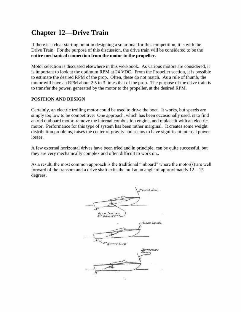
Chapter 12—Drive Train
If there is a clear starting point in designing a solar boat for this competition, it is with the
Drive Train. For the purpose of this discussion, the drive train will be considered to be the
entire mechanical connection from the motor to the propeller.
Motor selection is discussed elsewhere in this workbook. As various motors are considered, it
is important to look at the optimum RPM at 24 VDC. From the Propeller section, it is possible
to estimate the desired RPM of the prop. Often, these do not match. As a rule of thumb, the
motor will have an RPM about 2.5 to 3 times that of the prop. The purpose of the drive train is
to transfer the power, generated by the motor to the propeller, at the desired RPM.
POSITION AND DESIGN
Certainly, an electric trolling motor could be used to drive the boat. It works, but speeds are
simply too low to be competitive. One approach, which has been occasionally used, is to find
an old outboard motor, remove the internal combustion engine, and replace it with an electric
motor. Performance for this type of system has been rather marginal. It creates some weight
distribution problems, raises the center of gravity and seems to have significant internal power
losses.
A few external horizontal drives have been tried and in principle, can be quite successful, but
they are very mechanically complex and often difficult to work on,.
As a result, the most common approach is the traditional “inboard” where the motor(s) are well
forward of the transom and a drive shaft exits the hull at an angle of approximately 12 – 15
degrees.

From this figure, it can be seen that the angle of the drive shaft is very important.
Unfortunately, since the canoe hull was designed for paddling, not for a power system. In
2001-2002, over a dozen high schools were quite successful with a variety of configurations.
As a starting point, take time to study how the boat rides in the water with a skipper on-board.
Because the bottom of the boat is not flat from bow to stern, it is very important to estimate the
position of the aft portion –when the boat is in the endurance and especially the Sprint
configuration. By adding weight in the aft portion, a second person or sandbags, it is possible
to get a pretty good idea of the appropriate longitudinal center of gravity. (cg)
Once a desirable position is determined, place an “angle-o-meter” on the floor of the boat in the
area just aft of the bulkhead, where the motor(s) will be mounted. Once the boat is back on a
solid ground, position the boat on a solid surface and reproduce this angle. Viewing the hull
from the side, use a long straight edge to represent the shaft and adjust the position until a
desired position is found. Using a protractor, or the angle-o-meter, measure the angle between
the shaft and the bottom of the boat where the “strut” will be located. This will be the angle
you need for the strut. It will not be the same angle for the motor mount because the bottom of
the boat curves from front to back. The motor mount angle is likely to be about 2-3 degrees
smaller than the strut angle. If you buy a stuffing box or “log”, the angle of it will be slightly
less than the strut angle.
One easy way of adjusting these components into the correct alignment is to get everything into
the right position with the boat upside-down, drill mounting holes, and connect all components.
It will now be possible to inset spacers or wedges to come very close to the correct alignment.
By making up a paste of epoxy and filler, bond the spacers and sedges into position and double
check alignment. When the epoxy hardens, everything should be in the right place. It should
now be relatively easy with the hull right side up to determine the design and angle of the
motor mount.
SUPPORTING THE DRIVESHAFT
It is vital that the alignment of the shaft stays fixed. Turning at hundreds of RPM, forces are
very large. The most obvious force is the rotational one, caused by the motor. What is
sometimes overlooked is the thrust, created by the prop. There are essentially two way to
handle these forces. First, is what we will call the “pillow block” approach. In this design, two
pillow blocks are mounted internally; there is no external support of the drive shaft. The
second approach, common to most inboards uses an external bearing, mounted in a “strut”. In
either case, the forward bearing must carry both the radial load and the thrust load.
DRIVE SHAFT SIZE
In selecting the size for the shaft, a number of factors might be considered. (Quite a bit of
material is in the back of this section, which may prove to be helpful).
Strength – There are several features of a solid shaft that are desirable. It can be machined as
necessary from one piece of material. Its high strength to diameter ratio means that the

diameter can be kept rather small, thus reducing the external drag caused by it and its support.
One drawback is weight.
The alternative is a tube, as used in rear wheel drive cars. Here, a large diameter tube gives
very good strength but requires at least one fitting for the mounting of the prop. Some of the
weight that is saved with the lighter tube may be lost to heavier bearings, due to the increased
diameter. The larger diameter will also cause more drag as it goes through the water.
Length – It is not unusual to have a rather long shaft, to keep the shaft angle small. In
principle, the smaller the angle, the more thrust is directed forward. In other hulls, a long shaft
may help move the cg forward. With the ability to significantly adjust the cg in the hull being
used for Solar Cup, this is not important. Longer length can also lead to extra weight and
problems with wobble in the shaft.
Material – There is no doubt that synthetic material can be used for the shaft and, therefore,
achieves significant weight reductions; but this is not easy to do. Some form of steel is most
commonly used, since the boat is not being operated in salt water. (If it were, a brass shaft is
almost always used.)
Commonality – Although a particular diameter might seem best, it is important to remember
that it must be compatible with many other components such as pulleys, bearings and props.
Usually, either ¾” or 1” is used.
TRANSMISSION
Depending on configuration decisions for the Endurance and Sprint events, one may need a
fixed ratio transmission or a variable ratio transmission. If the design of the system only
requires a fixed reduction, there are gearboxes available, which are sturdy and can be ordered in
many ratios and shaft sizes.
In most applications, the optimum RPM needs to be changed and thus a variable ratio system is
needed. This means one or more pulleys or sprockets on the drive shaft and one or more on the
motor(s). Two connections systems are most commonly used. Traditionally, roller chain is
used because friction is low and the length is rather easily adjusted. In recent years, there have
been huge improvements in cogged belts such that their efficiency is as good as chain. The one
drawback is that the belts come in fixed lengths and thus the relative position of the motor and
shaft becomes very important.
Sprockets come in all sizes to that in the course of testing; it is not difficult to try more than one
ratio. Belt pulleys are also available in many sizes but changing them maybe more costly and
time consuming.
One final note of caution. If you have not worked with chain, you may not be aware that it
“stretches”. Do not undersize the chain or belt and be sure to have a tensioning system

ALIGNMENT OR COUPLING
Although a rigid sleeve type of coupler can join some components, it is often desirable to use a
flexible coupler. A common one is shown in the following pages. It uses a rubber “link”
between fittings that go on the ends of the shafts to be joined. This is only used when
alignment is good. The alternative is to use a “U” joint CV joint but there are reliability issues
as the angle between the two shafts increases. In any case, setscrews are often used to fix a
coupling on to a shaft. The failure of this attachment has traditionally been a real
problem. If possible, use a pin or bolt through the fitting and shaft. Even then, be certain the
bolt has sufficient strength.
MOUNTING
The floor of the boat is only ¼” plywood so it may not be suitable for the direct mounting of
components. Generally, some type of platform must be made, commonly out of aluminum, for
the mounting of the motor, transmission, and forward bearing. One great advantage of doing
this is for ease of testing. One possibility is that if the platform is a true module, it can be
tested either in or out of the boat. Large flat sheets of material should be avoided, as they will
flex. Structures using angle or box section material are usually lighter and much more rigid.
Once the platform is designed, the hull can be reinforced, if needed, and suitable fasteners
mounted in it in order to secure the platform.
STUFFING BOX
At some point in the drive train, it is necessary for the shaft to go through the hull. A stuffing
box is used to seal the area around the shaft and thus prevent water from leaking into the hull.
These boxes are available from various sources. One is Glen-L. Quite a bit of reference
material is included in the back of this section.
STRUT
If the drive shaft is supported externally at the aft end, it is done with a bearing in a strut.
These struts are available from various sources. Again, one is Glen-L. Quite a bit of reference
material is included in the back of this section.
SUMMARY
Many subsystems of the boat cannot be designed until the drive train design is determined.
These include the rudder, probably the steering, room for the batteries and their mounting, and
the bilge pump, just to name a few.
It is suggested that simple cardboard mockups, perhaps using a wood dowel or a piece of PVC
for the shaft, may be an excellent starting point. Once the concept is agreed upon, it is most
likely that it will be necessary to go to a machine shop to have some fabrication done.

Consider taking the hull and other parts of the drive train so the fabricator sees the whole
picture not just one part.

Power Conversions
(50 amp/hr)(24 V) (3600s/hr) = (4320000J)/(7200s) = 800 W * 85% eff = 510W total
Torque from Motor T = (6300 * Hp)/(rpm)
T = (6d300 * 12)/(1500rpm) = 504 lb-in
Shaft Sizing
½” solid shaft
J = (π/32)(D)4
J = (π/32)(1/2 in)4
= 0.006136 in4
= Tr/J
= (504 lb-in)(1/4 in)/(0.006136 in4) = 20534 psi
allow > 20534 psi
-assume a safety factor of 1.5
> 20534 psi * 1.5 = 30801 psi
/2 = 30801 psi
= 61603 psi <67000 psi
¾” * 9.12” wall shaft
J = (/32)*(DO4 – DI
4)
J = (/32)*(0.754 - .51
4) = 0.024421 in
4
= Tr/J (not sure about the backlash symbol?)
= (504 lb-in)*(0.375 in)/(0.024421 in4) = 7739 psi
allow > 7739 psi
> 7739 psi * 1.5 = 11608.9 psi
/2 = 11608.9 psi
= 23218 psi <67000 psi
Approximate Shaft Weight W = p(8/4)(Do)2 – (Di)
2)(L)
W=(0.3 lb/in3)(8)(9.375”)
2 – (0.225”)
2)(60 in) = 4.28 lb

Sprint Propeller Shaft Log Assembly
Strut Thrust Bearing
Inboard Assembly (Bottom Side) Inboard Assembly (Top Side)

Typical shaft log assemblies
Plate 37 – a method to determine the shaft angle for a straight shaft installation.
Propeller clearance calculation for inboard installations.


Reduction Gear


Sprint Motor configuration with the jack shaft support

Lovejoy Shaft Connectors


Chapter 13—Steering Throughout the history of the Solar Splash, the one area of design that has caused the greatest
problems on-the-water is the steering system. Perhaps one of the reasons is that it seems so
simple. This discussion divides the topic into two components the rudder and the system used
to move or control it.
Although it is possible to have unusual steering systems, the traditional rudder position in the
area of the stem and on the centerline of the craft is the only case that will be discussed. Other
configurations are possible but fraught with problems. For simplicity and reliability, this
configuration is strongly recommended.
THE RUDDER
The farther one looks into the shape of rudders, it becomes obvious that there are many designs.
Two examples of computer generated rudder designs are shown. Both are relatively square, as
compared with the very high aspect ratio rudders used on racing sailboats. High aspect means
long and thin.
Before selecting a design, there are really two key factors to consider, 1) strength and 2) what
are the turning demands? Going back centuries, the traditional rudder depends on the stern stem
or transom for its hinge points. This system is commonly known as a “pintle and gudgeon”
(P&G). In this system, the gudgeon is a fitting that mounts on the aft of the boat and provides a
hole, which forms a pivot with the pintle or pin that is mounted on the rudder. Two sets are
generally spaced as high and low as possible on the transom or stem for strength. To remove
the rudder, just lift up and the pintles come right out of the gudgeons.
The next mounting option is to have a vertical shaft go through the stem section of the boat.
This shaft is rigidly mounted and serves as a standpipe. The bottom of the outer shaft does not
have to be sealed against the rudder shaft because the top is well above the waterline. This is a
very positive way of mounting the rudder but removing it is somewhat difficult. By planning
for the rudder when designing the drive shaft and position of the propeller, there should not be
a problem with interference. This concept can be applied in two manners. First, the stern stem
can be used to support the outer tube. Carefully drill a vertical hole through the stern stem. The
outer tube can be secured in place with epoxy or other adhesive. The second method is to drill a
hole in the floor of the boat, just forward of the stem. This is easier but then requires metal
bracketry to support the top end.
The third method is sometimes known as a cantilevered rudder. In this design, the rudder is
only supported at the top and depends on very strong and well-engineered fittings and
materials. This method is not commonly used and is strongly discouraged.
The demands placed on the rudder are relatively small but the forces should not be
underestimated. For the Endurance, speeds are relatively low and thus the forces are

small, but, for the maneuverability course, it is necessary to negotiate a complex course with
tight turns. For the Sprint, the only demand is to keep the boat in a straight line, but speeds are
much higher and therefore, the forces are much greater. These forces can be calculated, but it is
necessary to know the boat speed, which will not be known until long after the rudder design
decision must be made. Be sure to leave yourself some flexibility so that the blade of the rudder
can be changed alter testing.
If the P&G system is used and the mountings are reasonably far apart, the forces on the rudder
will be minimized. If the rudder “blade” is made of a homogeneous material, it can be trimmed
down in size during testing.
It is not uncommon to make the cross-section of the rudder a very streamlined shape but this
can be very time consuming and very difficult to modify. All of these factors should be taken
into consideration when making the design decision.
Finally, without a keel, there is nothing to give the boat directional stability and assist in
turning. A keel adds drag, which is NOT desirable. An excellent alternative is a forward skeg.
A fin from a surfboard is very suitable. By mounting one on the centerline, about 1/3 of the
way back from the bow, the skeg gives the boat directional stability with minimum drag. At the
same time, it serves as a pivot for the rudder greatly improving steering and reducing the
requirements for the rudder size.
CONTROLS
We will refer to the system that controls the position of the rudder as the “steering”, for lack of
a better term.
The most basic steering system is a tiller, the handle on a coaster wagon. Move it, and the front
wheels move. Let go, and who knows what will happen. This system is simple but requires one
hand on the tiller at all times.
The system we are most familiar with is a “steering wheel”. No matter what the mechanical
linkage in a boat application, move the wheel to a new position and it will stay there until
moved again. This system is easy to use but relatively heavy and requires quite a bit of
mounting and hardware.
There are many hybrid systems that in essence combine the simplicity of the tiller and the
hands-off feature of the “wheel”.
Whatever system is employed, there are two elements that should definitely be adjustable. The
first is the attachment, point on the steering arm that is on the top of the rudder. If the
attachment point is too close in, there is a large loss of mechanical advantage. If it is too far out,
it takes a very large movement of the steering system to change the position of the rudder.

The second adjustable feature is the need to tension the cable or line that is used to interconnect
the components. Failure to tension this cable will cause a total steering failure. This can be
done with a turnbuckle(s) or spring(s) as the most common methods.
Finally, until testing begins, the fore-aft position of the skipper is not known. If possible, don’t
fix the position of the steering “wheel” until some testing can be done and the optimum
position of the skipper can be determined. This position is likely to be different for the Sprint
and the Endurance. The position should be a comfortable one for the Endurance as it lasts for
90 minutes. For the Sprint, it is highly likely that the skipper position should move
forward. Some method that allows the skipper to move their weight forward should be
considered.
Once the design of the drive train begins, and once the position of the prop is determined, the
rudder system can be designed and built. When doing this, be sure to consider the mounting for
the boat sign base.
It can be seen in Picture 6 that at the slower endurance speeds, the appendage drag is minimal.
But at sprint speeds of 25 knots or more, the drag becomes an unacceptable 13+% (i.e., 26 lbs)
of the tow test drag. Rudder depth adjustments will be made between competitions in order to
minimize this problem. The team may also manufacture a smaller aluminum rudder for use in
the sprint race.


Rudder with Pintle and Gudgeon Alternate Rudder with Pintle & Gudgeon
“Heavy” Non-adjustable Steering System

3.4 Steering System
The steering unit for this design is the rotary steering system. This unit is most desirable
because it can provide the needed performance in a compact design. The steering gearbox has
been secured to the aluminum tubular frame in front of the driver. The gearbox and steering
column is position at the center. This component is bolted onto the tubular frame. The cable
connecting the wheel to the outboard will run along the wall of the boat on the left side of the
skipper. For this design the outboard lower unit is the rudder. Figure 6a and figure 6b below is
a sketch and picture of the final steering system used. The rotary system is approximately $
200. The team was able to obtain this component at a discounted price of $ 135.
Figure 6a. Sketch of steering system used. Figure 6b. Picture of steering unit.

Drive System
The components of the drive system are the engine and drive shaft coupling, motor mount,
thrust washer, drive shaft, pillow block, PVC tubing, bronze oil light bushings, grease seals, o-
rings, and the propeller. The engine and drive shaft coupling consists of a gear on the motor
shaft meshed to a gear on the drive shaft. The lower gear is secured to the shaft by a keyway
and two setscrews. High strength spur gears are used in the sprint configuration to
accommodate the high torque and horsepower. Cast iron spur gears are used for the endurance
configuration since the horsepower is low. The largest spur gear, having a 9-inch diameter, is
webbed to reduce unwanted weight. The reduction ratio between the motor and drive shaft for
the sprint race and endurance race is 1.5:1 and 6:1, respectively. Along the drive shaft, a
collared pillow block bearing is used to keep the shaft aligned and receive a portion of the
propulsion force. Only one bearing was needed at the midpoint of the drive shaft due to the
shaft's material type and length. The drive shaft is made of TGP (turned, ground, and polished)
steel and is coupled with a tapered propeller shaft, which extends out the rear of the boat. The
coupling is contained in 2-3/8" outside diameter PVC tubing. The inside diameter of the tubing
is 2". The tubing contains grease seals, O-rings, and bronze oil light bushings to fit each shaft
accordingly. Fiberglass is used to affix the PVC tubing to the hull of the boat.
Drive Shaft Assembly
The motor mount is made of 1/4-inch thick high-grade aluminum. It supports the motors and
the drive shaft while allowing the gears to mesh properly. The motors are face- mounted to the
plate. The motor mount is mounted perpendicular to the drive shaft. A thrust washer and thrust
bearing ride against the block bearing which supports the drive shaft at the motor mount. The
motor mount is fastened to the boat with a special bracket that consists of angle iron welded to
special support plates on both ends and is supported at the bottom by two or more L-brackets
on either side, which are affixed to the hull with fiberglass. In addition, the engine mount
serves as a bulkhead, adding to the rigidity of the hull. A great attention to detail is used when
mounting the bulkhead to ensure that it is secured at the same angle as the drive shaft. This
detail eliminates the need for motor shims. The tapered propeller shaft is 13 ½" long and the
drive shaft is 5' 6" long. To achieve the maximum forward thrust force the drive shaft is placed
at the smallest angle possible. The distance from the propeller to the motor mount plate and the
diameter of the largest gear determined the angle of the drive shaft.

Drive Shaft Angle

Steering Cables Attached to Rudder Tiller
Steering Cables from Joystick
Joystick

Rudder Quadrant
Pulleys

Glenwood Marine Equipment
1627 West El Segundo Blvd
Gardena, CA 90249
323-757-3141

Chapter 14—Launching
Each team will have an assigned space of 20' x 20' under a large tent. This is known as the "Paddock" area. It is your home away from home for the Event. Although you may have your boat on your sawhorses, it is highly desirable to have a "dolly" which serves as a stand and as a means of transporting the boat down to the water. Since the area is ' blacktop, it is easy to move the dolly and some find it desirable to make the dolly with a lower shelf to transport various heavy items.
The tongue of the dolly has a removable handle and the front casters swivel while the back pair are fixed. It is important to remember that the weight it must carry at these times is likely to be upwards of 300 lbs. without any extra batteries, tools, whatever.
From the Paddock area, the boat is rolled into the "Staging Area" where it is re-inspected before each launching. Then it is on to the "On Deck" area for a final safety check. Typically, the boat can then be carried down the launch ramp and set in the water.

Chapter 15—Power Management
The goal of the Endurance event is to travel as far as possible in the time allocated. Overall system efficiency is critical.
Batteries &
Solar Panels
Motor
Controller
Motor Gears and
Linkages
Propeller
Figure 1.The major elements of a boat's drive system.
The overall efficiency of the drive system is the product of the efficiencies of the individual' systems. The goal of the system design is to get as much of the power from the batteries and solar panels to the propeller to provide thrust for the boat.
For example, say that the batteries and solar panels combined provide 600 W of power. Assume that the motor controller efficiency is 95%, the motor is 85% efficient, the gears and linkage are 98% efficient, and the propeller is 75% efficient. How much power is available to the propeller? How much power does the propeller produce?
The total efficiency of the controller, motor, and gears/linkage is:
Eff = 0.95 * 0.85 * 0.98 = 0.791 or 79.1 % efficiency
Therefore, the power available to the propeller is:
P = 600 W * 0.791 = 475 W (Power to the propeller)
The power output of the propeller is:
P = 475 W * 0.75 = 356 W (Power from the propeller)
So, an input power of 600 W results in only 356 W of power available for propulsion for the boat. This illustration shows the importance of the efficiency of each component involved in providing propulsion for the boat.
The first aspect of power or energy management is an efficient system. Once the system is designed and the boat is ready to compete, the second aspect of energy management is the use of the available power.
The energy from the solar panels is easy to deal with: use the energy as it is available. The energy from the batteries, however, is more complicated to manage. The energy in the battery should be consumed over the course of the Endurance competition. If the batteries are drained too quickly, the boat will be running on solar power only at the end of the competition. If the batteries are not drained by the end of the competition, then the boat did not travel as far as it could have.

The goal of power management is to completely deplete the energy in the batteries
over the course of the Endurance event.
The chapter on Batteries shows that the higher the current drain on the batteries, the less total energy will be drawn from the batteries. It follows from this fact that way to draw the most energy from a battery in a fixed amount of time is to draw a constant current that will deplete the battery in the specified time of the event.
Drawing a constant current from the batteries sounds easy enough to do, but there is no readily available, off-the-shelf low voltage DC controller that will allow for constant current draw from the batteries. Most motor controllers deliver a constant voltage to the motor, which results in a fairly constant motor speed. This speed will vary with wind speed and direction, water conditions (waves), and boat drag (it takes more energy to turn the boat).
Given enough electronics expertise a constant current controller for the batteries could be designed and constructed, but this is not a simple task. A more practical approach to this problem would be to install a battery state-of-charge meter, as discussed in the Instrumentation chapter. Battery condition can be monitored and controlled by keeping track of the amp-hours consumed from the batteries.
Testing the batteries in advance to determine the amp-hour capacity is very important - do not rely on the manufacturer's specifications. As discussed in the Batteries chapter, the manufacturer's amp-hour rating, even if reliable, is valid only at the specific value of current used to generate the rating.

Chapter 16—Instrumentation Instrumentation in a solar-powered boat can be very simple or quite complicated. The term "instrumentation" will be used in this document to mean “any measurement device used to give information to the skipper.” Instruments may include electrical meters that measure current, voltage, battery state of charge etc. There may also be devices that measure speed, temperature or motor rotational rate (rpm).
Measuring Voltage
Voltage is measured using a voltmeter. The voltmeter is placed in parallel with the device whose voltage is to be measured. Figure 1 shows the proper connection for a voltmeter when used to measure the voltage across a battery.
Figure 1. A voltmeter used to measure the voltage across a battery.
Voltmeters come in two basic types: analog or digital. Analog meters are usually powered by the circuitry whose voltage they are measuring. Digital meters usually require an external power source, so there may be more wiring involved However a more precise voltage reading can be obtained at a glance from a digital meter.
Many teams in the World Championship Solar Splash have used handheld digital multimeters that are hard-wired to the places where voltage measurements are desired. These meters have their own batteries to supply power.
Measuring Current
Current is measured with an ammeter. You must be careful to NOT place an ammeter in parallel with a source, especially a battery. An ammeter has an internal resistance known as a shunt, which has a very low resistance value. If the ammeter is placed in parallel with a battery a large amount of current will flow for a short period of time - either the fuse in the ammeter will burn up or the ammeter itself will bum up.

There are three basic ways to measure current
1. place an ammeter in series at the point in the circuit where the current measurement is desired
2. place an external shunt in series and measuring the voltage across the shunt 3. use a clamp-on ammeter
Method 1 is the least expensive method for measuring current Figure 2 shows a connection diagram for measuring current to the motor.
Figure 2. A basic wiring diagram for a solar boat with an ammeter for measuring motor current.
Measuring large currents often requires an external shunt or a clamp-on ammeter. An external shunt is a resistor whose value is known very precisely. The shunt is placed in series in a circuit just as the ammeter in Fig. 2 is. The voltage across the ammeter is measured, and the current passing through the ammeter can be calculated using Ohm's Law (I = V / R). Shunt specifications are usually given as the maximum allowable current and the voltage across the shunt at that current.
For example, a shunt's rating is given as 50 mV (millivolts, or 10-3
V) at 400 A. This means that if the
voltage across the shunt is measured as 50 mV, then the current through the shunt is 400 A. If the voltage
across the shunt is measured as 20 mV, then the current through the shunt is
1= (20 mV/ 50 mV) * 400 A = 160 A
It is not necessary to know the resistance of the shunt if the current and voltage specifications are known. However, the resistance of this shunt can be calculated:
R = V / I = 50 mV /400 A = 0.125 mohms, (the shunt resistance)
Note that this is a very small resistance value and will have little effect on the circuit.
A clamp-on ammeter has the advantage of not requiring the circuit to be broken in order to measure current. A magnetic coil is clamped around a wire and the magnetic field measurement is converted into a current measurement. Clamp-on ammeters are more expensive than shunt- type ammeter. Additionally, DC clamp-on ammeters are far less common than AC clamp-on ammeters.

Measuring Battery State of Charge
Determining a battery's state of charge by measuring the voltage across its terminals is not a very accurate method. The voltage across a battery depends on too many factors to make it a reliable indicator of the condition of the battery.
There are specialized meters that are designed for measuring a battery's state of charge. The E-Meter
TM by Cruising Equipment Co., shown in Fig. 3, is an example of such a meter. These
meters measures current, voltage and charge (amp-hours), and calculates various items of interest, such as time remaining and amp-hours used.
Figure 3. The E-MeterTM from Cruising Equipment Co. (www.cruisingequip.com)
Meters like the E-Meter require an external shunt and more complicated wiring than what is involved in wiring an ammeter or voltmeter. However, if a state-of-charge meter is installed properly the information it gives can be very useful in the Endurance event (see the chapter on Power Management).
How much instrumentation?
How many voltmeters and ammeters are needed? Is a state-of-charge meter necessary or just a cool thing to have? Is it important to know motor rpm or boat speed?
Let's start with the Sprint event. In the Sprint the goal is very simple: get to the finish line as fast as possible. It is not likely that you will deplete your batteries in the time it takes to run the Sprint. It is also not a good idea to be watching meters when your boat is traveling at high speed. For testing purposes, you may want to know how much current the motor is drawing, how fast the boat is going, or what the motor rpm is. But, in the actual event, knowing these things will probably not affect any decisions you make.
If you are basing a decision on some parameter, then you should measure that parameter.
If you are not basing a decision on a particular parameter, then why complicate things by measuring that parameter?

The Endurance event is a longer, more complicated event with slower speeds and more time for
the skipper to make decisions. Therefore, more instrumentation is appropriate. If you are going
to base decisions on the battery voltage level, then it would be appropriate to have a battery
voltmeter. If you want to monitor the current from the solar panels, then place an ammeter in
the solar panel circuit. But, unless you have some means of controlling the solar panel current,
then you need to consider whether knowing the solar panel current is essential.
Keep in mind that too much instrumentation can be confusing and distracting. More
instrumentation may be desirable while testing, but you may find that you don’t need all of’
that information to make the necessary decisions during the actual event.
At a minimum you will probably want some means of determining your battery’s state of
charge. You will probably also want to know how much current you are drawing from the
batteries at any time. Additional instrumentation can be added to the circuits fairly easily, but
the positioning of the displays should be thought out carefully in the design of the skipper’s
“cockpit” area.

Chapter 17—Strategies
It might seem as if the only event that requires a strategy is the Endurance but consider
this: In at least two of the. 9 years of the Splash, not completing the maneuverability
course on the first run cost one or more schools the World Championship.
The very best and easiest strategy is to have enough practice with your boat to qualify in
both configurations on the first try. Next, do not have one skipper who can do it but be
sure to have two. You never know when you will need your backup.
Next, know the rules!! Not being familiar with all the rules could cost you precious time
and avoid an unnecessary penalty.
The focus of this discussion will be on those elements to consider in running the
Endurance Event. They include: available stored power, available real time solar energy,
elapsed time, and how much energy is being consumed.
In a perfect world, you would like to be able to run the boat in the endurance
configuration on batteries alone to see how long they will last under competition
conditions, If they run out early, then you will have to reduce speed, Once this is
measured or calculated (risky), it is best to use solar energy to increase your speed to
whatever conditions exist. If you determine you can run for 90 minutes at XX amps,
control the output of the batteries to that drain.
The riskier approach is to estimate what the weather conditions will be; hence, the
amount of incoming solar energy. Combine that with the amount of stored energy and run
the boat at the speed you think you can sustain.
The key thing to remember is that you don’t want to finish with only half drained
batteries but conversely, if you have to run on solar only for the last 20 minutes, you may
be passed by many “turtles”.
In summary, to optimize your overall score, do as well as you possibly can in all events.


Lessons Learned
By a Faculty Advisor
Competing in a Solar Cup Competition
1. Familiarize yourself with the purchasing requirements for your school.
How much lead time do you need to pay for equipment and material required for
the boat?
Do certain approved vendors by the District bind you?
Can you purchase materials and equipment and be reimbursed by your school?
Do you have to obtain bids for purchases?
2. Identify staff and student groups that can support your team’s participation in the
Metropolitan Water District’s Solar Cup.
Does the computer lab have CAD software and capabilities for design ideas and
improved technical report submissions?
Can you link your team’s participation and help needed to the school’s web page?
Does the school newspaper and/or yearbook staff have contacts in the business
community?
Can students working on the team receive any type of elective credit and/or
school time to complete this project?
What resources can you obtain from both certified and classified staff at the
school to help in the areas of electrical design; mechanical design; availability of
power and hand tools; facility to work on and store the boat and equipment?
3. Communicate, communicate, communicate!
Identify those things your team will be involved in and advise your administrator
in the beginning of the project.
This includes students who may need training in how to use certain power and
hand tools for working on the boat
When and where you will be testing this boat in the water with students.
Will students be interviewed by the media and are they prepared?
Communicate to parents of team members about the project and the commitment
that will be required of team members.
Let parents know the team’s work schedule including after school hours,
weekends, and holidays.
Make a list of things you may need help with including, but not limited to,
financial support for non-boat related items, transportation, food, equipment,
specialty expertise, i.e. (electrical, welding, mechanical, communication
equipment, etc.).
4. Communicate with you local water district member sponsor.
5. Communicate when necessary with Metropolitan Water District.

My Top 10 Do’s
1. Remember the KISS Principle “Keep it simple stupid”.
2. Empower student team members!
3. Make a plan for all aspects of the project!
4. TEST, TEST, TEST!!!
5. Read the rules and workshop manual!
6. Meet frequently!
7. Communicate frequently with the MWD Tech Team
8. Use all the resources you community has!
9. Include anyone with an interest and dedication!
10. Take Pride in what you build and present

1
Chapter 18—Technical Reports Two reports, each worth 25 points, must be submitted to the Metropolitan Water District during
the Solar Cup program. This chapter outlines the rubric used for grading these reports and the
timeline listing the due dates. Use these as guides to assist you in formatting your reports.
The primary goal of a report is to convey technical concepts as clearly as possible. This will
require both clear diction and appropriately labeled figures. A common problem in technical
reports is the inaccurate depiction of the true shape and size of the hull or other components. We
suggest using and referencing material provided in the Technical Manual and workshops to
insure the accuracy of the hull and component characteristics. The physical dimensions (length,
height, width) of relevant components should be included in relation to the hull.
Innovative designs are wonderful and we strongly encourage them as long as they conform to the
Solar Cup rules. Please keep in mind that your overall success in the Solar Cup event will depend
more on the reliability of your design. You are encouraged to discuss the reliability of your
design within each report.
Quality designed systems are based on theoretical calculations and experimental evidence. Even
simple calculations provide enormous insight into a design problem. Report scoring is heavily
weighted in favor of discussion of evidence and calculations.
All reports should be original bodies of work written by student team members. Students are
expected to amass and reference material from a variety of sources in order to synthesize a report
in their own voice. Reports from veteran teams will be compared to submissions from previous
years. Report scoring is heavily weighted to discourage plagiarism.
You will receive feedback in writing after submitting each report. Consider it carefully! If you
don’t understand or if you want to verify that you do, please don’t hesitate to contact Julie at
Metropolitan with questions.
Reports will only be accepted electronically. If your report is larger than 5mg you may have
trouble emailing it. If you have a large file, save your report (in .pdf format) on a CD and mail it
to Royetta via regular mail.
EMAIL — [email protected]
US Mail for CD’s only — Metropolitan Water District
700 N Alameda St.
Los Angeles, CA 90012
Attn: Royetta S. Perry

2
PLAGIARISM
The basic rule is this: If you include material drawn from any source beyond your own firsthand
experience, and if this material is not common knowledge of the kind possessed by everyone
working in the general area, you must give credit for that material in a reference that identifies
the source by author, date, title and page (or, if the source is not something in print, by details
about the source that are equally precise).
Specifically:
If you quote directly from your source, you must enclose the quoted material, even if it is
no more than a phrase or a single word, within quotation marks, and provide a reference.
If you paraphrase--that is, restate the material in your own words--(a) the paraphrasing
must represent a substantial change from the original, not just the changing of occasional
words and phrases, and (b) you must provide a reference.
If you present material that is common knowledge, but borrow someone else's
organizational pattern, you must acknowledge that use in a reference.
If the language and organization are your own, you must still acknowledge any ideas or
information that are not common knowledge in a reference.
Whenever you are in doubt whether to acknowledge borrowing, a good rule is to ask yourself:
Could a reader who consulted the books and articles listed in my bibliography recognize in my
paper sentences, phrases, words, patterns of organization, interpretations, points of view, ideas or
facts as deriving from one of these sources?
If you can, you must cite the source of such passages and use quotation marks where needed.
Any clear parallel between your paper and its sources which a reader would discover if he/she
consulted your sources should have already been indicated through your references.
Source: Occidental College, STUDENT HANDBOOK, 2003-2004, p. 53

3
Solar Cup 2017
Technical Report Details
Electronic versions of all reports are due to Royetta S. Perry at Metropolitan Headquarters by
5:00 p.m. of the due date.
Reports should be from 1000 – 2000 words in length (five to ten pages) not including
figures, tables, a bibliography and reference materials.
You are strongly encouraged to employ a Technical Writing Style that formally and
clearly conveys your ideas.
Technical reports must be written by students with support from teachers and mentors.
Plagiarism is to be avoided and references should be properly cited.
Reports should include a Title Page, Table of Contents, List of Figures, Introduction,
Body of Report, Conclusion, Bibliography, and Appendices for reference material.
Figures should be numbered, titled and labeled with an appropriate caption.

4
Drive Train/Steering Report is due January, 5 2017
This report should include a narrative and design diagram detailing your proposed Drive
Train/Steering system. Use calculations and/or measurements to discuss how components impact
the center of mass and center of buoyancy of your craft. Be sure to include the following
electrical components in both the diagram and narrative:
A top/bottom and side view of the drive train with the outline of the hull and bulkhead
shown.
Information on the angle of the drive shaft and the consequential angles of the stuffing
box and strut.
Necessary text to accompany the diagram. The text needs to identify components such as
the motor(s), drive shaft, etc.
The information should be detailed enough so we understand your approach.
Steering portion: Experience has shown that although steering may be the simplest system in
the boat, it often does not get the attention that is needed. Include depictions of side and
top/bottom views of the steering system in your report. Text should include information about
the components. A drawing of the rudder(s), which includes dimensions, is necessary.
Drive Train/Steering will be worth 25 points. Veteran team reports will be compared to team’s
previous report submissions and graded original content based on the following criteria:
Punctuality (3pts.)
Introduction (3pts.): Title Page, Team Advisor, Team Members, Contact Info, Table of
Contents
Methodology (5pts.): Design Considerations, Problem Solving, Organizational Strategy
Supporting Technical Material (5pts.): Tables, Schematics, Block Diagrams, Data,
Graphs, Illustrations, Calculations
Conclusions/Summaries (5pts.): Critical Analysis, Data Interpretation
Grammar and Clarity (4pts.): Neatness, Legibility, Brevity, Spelling, Attributions

5
Electrical/Solar Report is due February 15, 2017
This report should include a narrative and design diagram detailing your proposed electrical
system and solar array. Use calculations and/or measurements to discuss the power, current, and
voltage of the electrical components. Be sure to include an introduction on the physics of
photovoltaics and the following electrical components in both the diagram and narrative
(including component manufacturer, rated voltage and rated wattage):
Batteries , Solar Panels, Motors, Motor Controller, Bilge Pump
Dead-man switch, 350 Amp fuse, Wire size
Drawings that show the relative position of the solar panels on the hull from a top
view and a side view.
Your solar panel/hull attachment technique must be shown. (There is a
requirement in the rules that the panels must be mechanically attached to the hull.
Velcro is not an adequate solution.)
Electrical/Solar reports will be worth 25 points. Veteran team reports will be compared to team’s
previous report submissions and graded original content based on the following criteria:
Punctuality (3pts.)
Introduction (3pts.): Title Page, Team Advisor, Team Members, Contact Info, Table of
Contents
Methodology (5pts.): Design Considerations, Problem Solving, Organizational Strategy
Supporting Technical Material (5pts.): Tables, Schematics, Block Diagrams, Data,
Graphs, Illustrations, Calculations
Conclusions/Summaries (5pts.): Critical Analysis, Data Interpretation
Grammar and Clarity (4pts.): Neatness, Legibility, Brevity, Spelling, Attributions
Grammar and Clarity (4pts.): Neatness, Legibility, Brevity, Spelling, Attributions

6
Rubric for Technical Report Evaluation: MWD Solar Cup. Team Name ___________________________________ Team Number ____ Total Score _____
Criteria DRIVETRAIN/STEERING ELECTRICAL/SOLAR RUBRIC
Punctuality
3 Points – Report is submitted on-time 1 Point – Report is late due to
extenuating circumstances
office contacted before due
date/time.
0 Points – Report is late no
contact made before due
date/time.
Introduction
3 Points – Report includes detailed
introductory information, Report
contents well presented and very
helpful to the reader.
1 Point - Report provides
adequate introductory
information. Report contents
adequately presented and
useful to the reader.
0 Points - Writer provides
little if any introduction
information. Report contents
not well presented to
significantly aid reader.
Methodology
5-4 Points - Report provides detailed
information regarding design
considerations and methodology.
Evidence of significant and reasonably
comprehensive literature
research/review included.
3 Points - Report provides
adequate information
regarding design
considerations and
methodology. Evidence of
literature review/research
included.
2 Points - Report provides
some information regarding
design considerations and
methodology. Little evidence
of literature review/research
included.
1 Point - Report provides
minimal or no information
regarding design
considerations and
methodology. No
evidence of literature
review/research included.
Supporting
Technical
Material
5 Points – Technical material detailed
and accurate. Diagrams, calculations,
illustrations, graphs/tables add
significantly to the reader's
understanding. Significant contribution
of material generated by team.
4 Points – Technical material
accurate and adds to the
reader's understanding of the
topic. Some material
generated by team.
3-2 Points - Technical
material generally accurate
and sometimes add to the
reader's understanding. Little
or no material generated by
team.
1 Point - Diagrams are not
accurate OR do not add
significantly to the
reader's understanding. No
material generated by
team.
Conclusions/
Summaries
5 Points – Significant evidence of
sound data analysis. Conclusions data
driven, well constructed and succinct.
4 Points - Evidence of good
data analysis. Conclusions
well constructed and succinct.
3-2 Points - Some evidence of
data analysis. Conclusions
somewhat well constructed.
1 Point – Little or no
evidence of data analysis.
Minimal or poorly drawn
conclusions.
Grammar and
Clarity
4 Points – None or inconsequential
grammatical or spelling errors.
Appropriate attributions of data
sources. Writing generally clear and
concise.
2 Point - Some grammatical
or spelling errors. Appropriate
attributions of data sources.
Writing generally clear and
concise somewhat verbose.
0 Points - Many grammatical
or spelling errors. Incomplete
or no attributions of data
sources. Writing unclear and
difficult to read.