solar cells, 22 (1987) 29 - 46 29cronin/solar/references/shade effects... · solar cells, 22 (1987)...
TRANSCRIPT

Solar Cells, 22 (1987) 29 - 46 29
A GENERIC APPROACH TO THE SHADOW EFFECT OF LARGE SOLAR POWER SYSTEMS
PETER P. GROUMPOS and KAMEL KHOUZAM*
Energy Research Center, Department of Electrical Engineering, Cleveland State University, Cleveland OH 44115 (U.S.A.)
(Received September 25, 1986 ; accepted December 17, 1986 )
Summary
The design of large-scale solar power systems (photovoltaic or thermal) of different kinds is increasing and the shading effect of neighboring collec- tors becomes critical for the optimal design of such systems. The shading of collectors by their neighbors is likely to occur during some period of the day, especially near sunrise and sunset. It is desired that any shadow be minimized throughout the day. The shading effect depends on the spacing between collectors, the row length, their height, the tilt angle, the latitude, the type of collectors and the time of year.
The work reported here presents a generic mathematical framework which is used for the analysis of the shadow effect of large solar power systems. A new measure, the shadow efficiency, is defined and determined as a funct ion of a number of important parameters affecting the shading effect. The shading effect of collectors for the three possible collectors' orientations, fixed tilt, half-tracking and full-tracking, is discussed. Using the shadow efficiency as a measure of performance, a new way to determine acceptable distances be tween collectors is outlined. A number of simulation studies are reported and discussed.
I . Introduction
When solar arrays (photovoltaic and/or thermal) are arranged in mul- tiple rows of panels, all bu t the first row suffer a reduction in power output , even when sufficient spacing between the rows is provided. Indeed, in any solar power system where a number of collectors (photovoltaic and/or thermal} of different kinds are used to collect solar energy, the shading of collectors by their neighbors is likely to occur during some period of the day, especially near sunrise and sunset. The reduction in ou tpu t power occurs because front rows prevent some of the solar radiation from reaching
*On leave from Ain-Shams University, Cairo, Egypt, under the Egyptian Channel System.
0379-6787/87/$3.50 © Elsevier Sequoia/Printed in The Netherlands

30
rows behind them. It is desired that any shadow be avoided or be restricted to small periods of time.
Studying the shading effect is an interesting and challenging problem and is a multiparameter-multiobjective problem. The shading effect depends on the spacing between collectors, their dimensions, their type, the tilt angle, the time of year and day and the latitude, The shadow effect has previously been investigated and interesting results have been reported [1 - 4]. In ref. 1, an analytical-numerical method is presented for the evaluation of the shadowing effect in a typical solar power plant made of N lines of concentrating cylindrical-parabolic collectors tracking the sun by running around on an east-west-directed horizontal axis. The diffuse radiation was neglected and the only objective that was used was to maximize the annual collected energy. The study in ref. 2 is more detailed where the shading effect of fixed vertical and fixed inclined poles and collectors and its signif- icance to the design of a large-scale solar system is fully investigated. The shading effect between two south facing rows placed one directly behind the other, for the beam, diffuse and reflected components of radiation, has been investigated in ref. 3 while ref. 4 includes the effect of ground offset and ground reflectivity. The results of ref. 3 showed that the percentage decrease in total radiation received by solar panels behind the front row varies from 1% to 4% depending on the latitude, month , tilt angle and row- to-row spacing.
This work presents a generic mathematical formulation of the shading effect. Here we elaborate and discuss a generic mathematical formulation of the shading effect that has been developed in ref. 5. A new measure is defined, the shadow efficiency ~sh, and determined as a function of a number of parameters being considered. This new generic approach permits us to investigate the shading effect of collectors for all three possible collec- tors' orientations, fixed tilt, full-tracking and half-tracking, using the same mathematical model. Furthermore, the newly introduced figure of merit, the shadow efficiency ~h , provides us with a new way to determine dis- tances between collectors for any desirable ~sh at any latitude for any of the three possible collectors' orientations and for any time of year.
2. A generic mathematical formulat ion of the shading effect
The shadow effect of a vertical pole and collector has been extensively analyzed in ref. 2. It is also shown there that the study of the shadow effect of an inclined pole and collector is similar to the study of the vertical case. Indeed, the vertical position is a special case of the varying inclined position. Therefore, we will concentrate only on the inclined case.
2.1. Shadow analysis A pole of length u (see Appendix A) in the z -y plane inclined at
an angle ~ and oriented at an angle 0 is shown in Fig. 1. The shadow length P is ~ and the shadow components are

31
\o,
I"
S ~__ PY
/ x C
/ /
/ /
/ Px /
YN /
Fig. I. The shadow components P, Px and Py of a general inclined pole.
Px = u cos q sin 0 + u sin Z cot ~ sin (1)
Py = u cos o~ cos 0 + u cos Z c o t ~ s in (2)
# = tan-~(P~/Py) (3)
where Z is the azimuth angle of the sun (positive in the afternoon) and is the elevation angle of the sun.
The general view of the shadow of an inclined pole on an inclined collector is shown in Fig. 2. The pole shadow on the ground is ~gg and its shadow on the collector is ~ . The coordinates of the point e are determined from the intersection of the three planes mm'l l ' , bco' and oco'
X - - u c o s a s i n 0 Y - - u c o s ~ c o s 0 bco': =
P x - - u c o s ~ s i n 0 P y - - u c o s o / c o s 0
YPx - - XPy oco': Z = tan
P~ cos 0 --P~ sin 0
mm'll ' : Z = ( ( Y - - d ) c o s 0 ' + X s i n 0 ' } tan a '
Considering the case ~ = a ' and 0 = 0 ' and solving for Ze, we obtain
Ze = u sin a Px tan 0 + Py (4)
The coordinate Xg of point g is given by

32
\ \o'
i i °
ol A ~ I \ ~ . , . - 2 , / S - 11 ~ . I \ . ~ J . ~ I . A - - I
/ "~..~ y I",° i / \ b, / ~/ "\ I
P' ¢ 2
/ \ ; / ~ x I s " ~ /
P Y Y, N
I I
I /
I/Px
Fig. 2. The shadow caused by the inclined pole oo' on the inclined collector mm'll' in a general position.
\ \
,, i%
Fig. 3. Two collectors in the normal tracking position.

33
N'0 N'I
\ \ \ N'2
v~h2
\ \ \
\ \
>~ z'g \
/ \ /
/c N'3 \
"\ g /,,
/ \ / #
/ / i /
/ / / /
,z / j k / . /
//~g N'4//
Fig. 4. A field of sun tracking collectors and the shadow caused by N'0.
Xg -- P~d
Px tan 0 + Py (5)
Figure 3 describes the position of two parallel collectors. It can be shown that the shaded area is rectangular and is given by
A m = UshVm (6)
where Um is the shadow height
Ze um - (7)
sin c~
and Vm is the shadow length
Xg vm = v (8)
cos 0
Am cannot be negative. If u m or v m are negative, then Am equals zero. Let us consider a field of tracking (or fixed) collectors as shown in
Fig. 4. The shaded area caused by collector N'0 on any other collector in the field is given by eqn. (6) where

34
l d+(i--1)wtanO I (9) Z e = u s i n ~ 1 - - P ~ t a n 0 + P y
Xg = Px l d + (i-- 1)w tan 0 I t PxtanO+Py (10)
Z e u~ - (11)
sin a
I X s - ( i - 1)wl v~ = v - (12)
cos 0
where i is the collector number starting at 1 for the collector just behind N'0 (to the north). A special case will occur if collector N'0 shades more than one collector at a time. In this case,
(i - 1 ) w - x ~ vsh = v + if w < Xg (13)
cos 0
Z g - - Z g , Vsh = v + if W > X~ (14)
COS 0
Xg - - ( i - - 1)w v~ = v + if w >Xg, (15)
cos 0
where
Xg, = Xg + vt cos 0 (16)
vt is the total shadow length (]gv~) occurring on the previous collectors and Vsh = 0 if Vt /> V.
Here shadowing will not occur on any collector, i ~> 1, if any one of the following conditions is met
Py < {d + (i -- 1)w tan 0} cos20 (17)
p>tan-'t(i--d--vsino1)w+vc°s 0 f (18)
P < t a n _ i t ( i - - 1 ) w - - v cos 0 f d + v sin 0 (19)

35
2.2. Shadow analysis for different collectors' orientations The above general mathematical analysis can be applied to any of the
following cases: full-tracking, a = 90 ° - ~, 0 = Z; half-tracking, ~ = 90 ° - / ~ , 0 = 0; fixed collectors, a is equal to the latitude of the collector, 0 = 0. Let us define the relative shaded area R m for collector N ' I as
Am Rm - (20)
UV
{ d } = 1 - - -- f l (H,5 ,L) 1 - - f2(H,6,L) (21) u R
where fl and f2 are functions of the hour angle H (positive in the afternoon), the declination angle 6 of the sun and the latitude L of the site. R is the length-to-width ratio.
I t is concluded that Rm depends on the ratios R and d/u. This result was obtained for fixed collectors in ref. 1. Again for i~> 2, the relative shaded area is given by
which shows that Rm depends on R, d/u and w/u. Now let us define the shadow efficiency ~Tsh to be
~m = (I --Rm) × I00
The ground coverage ratio G c is defined by
uv Gc - × I00
dw
where w is defined as
W - - - - V + C
(23)
(24)
(25)
with c a constant.
3. Simulation studies and discussion of results
A computer model based on the above analysis and using previous results [6, 7] has been developed in order to calculate the overall daily shadow efficiency [5]. The computer model of ref. 5 is a general model and can be used to analyze carefully and investigate the shadow effect of large solar power systems. A number of simulation studies have been per-

36
TABLE 1
Declination angle 6 of the sun for the nine selected days
Date 6 (deg)
February 9 -- 15 March 8 -- 5 April 2 5 May 1 15 August 25 10 September 7 5 October 2 --5 November 1 --15 December 21 --23.4
"sh%[ i00 T
99
98
97
96
95
9~
93
I! l
I t 3 I &[O t 0 . 8 1 . 6 2 J 4 .~ 4 . 8 R
Fig. 5. The shadow efficiency vs. R with d/u = 2.0 on December 21st for full-tracking collectors of different areas: -- • --, 20 m2; . . . . ,40 m2; - , 60 m 2.
f o r m e d in ref . 5. I n t h e w o r k r e p o r t e d he re , we have c o n s i d e r e d t w o r o w s o f five co l l ec to r s . A s u b r o u t i n e was u s e d to c a l c u l a t e t h e s h a d o w e f f i c i e n c y fo r c o l l e c t o r s N ' I - N ' 5 . T h e i n p u t p a r a m e t e r s t o t h e s u b r o u t i n e are t he f ie ld p a r a m e t e r s v, u , d a n d w, t he angles of t he s u n Z , ~ a n d H , a n d the angles of t he c o l l e c t o r s ~ a n d 0.

37
nsh%
100
99
98 ~ Latit
97
96
94 I I I I I I Oct:. Nov. Dec. Jan. Feb. Mar. Time
Fig. 6. The shadow eff ic iency as a f unc t i on of t ime of year for full- tracking col lectors wi th d / u = 2.0 and R = 2.0.
In performing the calculation, solar time is used starting at H = 0 and ending at H~ with 3.75 ° intervals (corresponding to 15 min). Nine days around the year were selected, including December 21. The nine selected days are shown in Table 1. The solar angles were calculated according to refs. 6 and 7 which take into consideration the atmospheric refraction.
Collector areas between 20 and 200 m 2 with different ratios R between 0.1 and 15 are used in the analysis. Site latitudes between 10 ° and 50 ° are taken into account. The constant c of eqn. (25) is taken to be 2. The shadow efficiency is obtained for the three cases of full-tracking, half-tracking and fixed collectors.
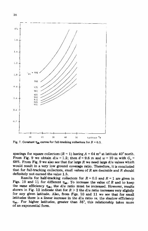
Figure 5 shows the efficiency ~&h as a function of R for different collector areas. These results indicate that r&h is independent of the collector area for large areas and for high R. The deviation introduced for smaller areas and small R is due to the ratio w/u which affects the efficiency as we have shown mathematically in Section 2. The variation in ~sh as a function of the time of year for full-tracking collectors is shown in Fig. 6. As expec- ted, the shadow efficiency for smaller latitudes is higher and reaches a mini- mum value for the same latitude during the months of November or Decem- ber. Constant efficiency curves are given in Figs. 7 and 8 for R = 0.5 and R = 1 respectively. The figures give the ratio d/u for any desirable efficiency whereas w is taken equal to v + 2. Figure 9 gives the ratio d/u for various ratios R for the case of full-tracking collectors and different latitudes for ~sh = 95%. For example, let us suppose it is required to determine d and w
38
d/u
1.6.
1.4
1.2
1.0 qsh = 99%
98%
0.8 97%
96%
95%
0.6 94% 93% 92% 91~
0.4
0.2
10 20 30 40 50 Latitude ON
Fig. 7. Constant ~ h curves for full-tracking collectors for R = 0.5.
spacings for square collectors (R = 1) having A = 64 m 2 at latitude 40 ° north. From Fig. 9 we obtain d/u = 1.2; then d = 9.6 m and w = 10 m with Gc = 68%. From Fig. 9 we also see that for large R we need large d/u values which would result in a very low ground coverage ratio. Therefore , it is concluded that for full-tracking collectors, small values of R are desirable and R should definitely no t exceed the value 1.5.
Results for half-tracking collectors for R = 0.5 and R = 1 are given in Figs. 10 and 11 for different ~?ah. To increase the value of R and to keep the same efficiency WJh, the d/u ratio must be increased. However, results shown in Fig. 12 indicate tha t for R > 2 the d/u ratio increases very slightly for any given latitude. Also, f rom Figs. 10 and 11 we see that for small latitudes there is a linear increase in the d/u ratio vs. the shadow efficiency 7/~h. For higher latitudes, greater than 35 °, this relationship takes more of an exponent ia l form.

3 9
q L
o
I I ~ I ' I ; i , I
u ~
e ~
o
II
I i t I t * l I ~ I ' ; I , I
o
o
o
i ,
II
0
0 0

40
~ ' I , I , I ' I , I ' I
z c
g
. o
o
a :
0
0
e~
0 o
. e l
f l
' J . ' . 4 ' ~ '
c z O
II
5 0
~ e
2 ~
e~
0 r..)
6
N

41
J

42
I ~F
I , I , I i ! ~ I ~ I , I
II
Q
~4
@
I I 1 i i ~ 4 , i } I
o
@
c3

48
11
I , I i I ' I
• o •
oll I ~ I
o co
i
,.o
I l
II
e~
@
~=~
II
Iii
0
III
,,o ~ N • , o
Ii
. . . . . o
U
0

44
The shadow efficiency as a function of d/u for fixed collectors {where is equal to the latitude in degrees) is shown in Fig. 13 for December 21
only. From Fig. 13 we see that the shadow efficiency for large latitudes in- creases almost linearly with the ratio d/u. However, for small latitudes, this increase exhibits exponential growth for small d/u (e.g. L = 20 ° and d/u values less than 1.5) and then it saturates which means that large d/u ratios should not be used for such latitudes. For example, for L = 10 °, it would be a waste of land to use any d/u value above 1.3 for a high shadow efficiency of 98%. The results also show that for small latitudes, L ~< 30 °, the ratio R will have a very low effect on the shadow efficiency ~sh for the same value of d/u.
Results for constant ~sh curves for the case of fixed collectors and for R = 0.5, R = 1 and R = 3 are given in Figs. 14, 15 and 16 respectively. Sim- ilar comments to those made on the half-tracking collector results of Figs. 10 and 11 can be made here. What is interesting in comparing Figs. 10 and 11 with Figs. 14 and 15 is that the results are very close to each other. Small differences exist with the fixed case exhibiting slightly higher shadow efficiencies for all latitudes and for the two R values of 0.5 and 1. These results are only for December 21. When we compare the yearly results, this observation does not hold [5].
Recommended values for fixed collectors for d/u ratios for different R values and latitudes are shown in Fig. 17. For a large range of R, d/u should be constant.
4. Summarizing and closing remarks
The problem of the shading effect on large solar power systems has been considered. A number of important parameters affecting it have been identified. A brief review of other studies has also been provided. A generic mathematical formulat ion of the shading effect has been presented and used to investigate this effect for collectors for all three possible collectors' orientations: fixed tilt, full-tracking and half-tracking. A new performance measure was defined, the shadow efficiency ~h . The shadow efficiencies for various input parameters can be calculated for all three orientation cases.
An interesting result that was obtained indicates that full-tracking collectors require more space between them than half-tracking and fixed collectors do. In other words, the ground cover ratio is highest for fixed collectors. Therefore, in order to utilize better the land for full-tracking collectors, it is recommended that a small ratio of R be used.
As was pointed out in Section 1, the shading effect is a multiparam- eter-multiobjective problem. In the work presented here, no optimal system design was at tempted. Hence future research related to the shading of collectors should be directed to the optimal system design. A total opt imum system design solution has not yet been worked out as was also indicated

45
in ref. 2. The shading effect should also be investigated when the total radiation (the diffuse radiation as well as the ground offset and the ground reflectivity effect) is considered [4, 5]. In addition, for the case where rows are elevated above the ground, their effect on the shading effect is an inter- esting problem. Some interesting results have been obtained in ref. 5 and will soon be submit ted for publication.
Acknowledgment
The work of Peter P. Groumpos was supported by the State of Ohio under the Research Challenge Program.
References
1 0 . Barra, M. Conti, E. Santamata, R. Scarmozzino and R. Visentin, Shadow effect in a large-scale solar power plant, Sol, Energy, 19 (1977) 759 - 762.
2 J. Appelbaum and J. Bany, Shadow effect of adjacent solar collectors in large-scale systems, Sol. Energy, 23 (1979) 497 - 507.
3 E. K. Stefanakos, D. Y. Goswami, A. Y. Hassan and W. Collis, Effect of row-to-row shading on the output of flat-plate south facing photovoltaic arrays, Solar Engineering 1986, Proc. ASME Solar Energy Conf., Anaheim, CA, April, 1986, American Society of Mechanical Engineers, New York, 1986, pp. 163 - 174.
4 D. Y. Goswami, M. Barshooi and E. K. Stefanakos, Effect of ground reflectivity and ground offset on the row-to-row shading of fiat plate solar arrays, Solar Engineering 198 7, Proc. ASME Solar Energy Conf., Honolulu, HI, March 22 - 2 7, 1987, American Society of Mechanical Engineers, New York, 1987.
5 P. Groumpos and K. Khouzam, A general mathematical framework for the analysis of the shadow effect of large solar power systems, ERC-R-13, 1987 (Energy Research Center, Department of Electrical Engineering, Cleveland State University), to be published.
6 R. Walraven, Calculating the position of the sun, Sol. Energy, 20 (1978) 393 - 398. 7 B. J. Wilkinson, An improved FORTRAN program for the rapid calculation of the
solar positions, Sol. Energy, 27 (1981) 67 - 68.
Appendix A: Nomenclature
A Ash d
Ve H Hu P, Px,Py R
collector area shadow area distance be tween collectors in the nor th - sou th direction (center to center) ground coverage ratio solar hour angle sunset solar hour angle shadow components of an inclined pole v/u, length-to-width ratio

46
Rsh /L
Ush V
Vsh W
Z
relative shadow area collector width shadow height collector length (horizontal length) shadow length distance between collectors in the east-west direction (center to center) sun azimuth angle
Greek symbols collector tilt angle
/3 sun altitude (elevation) angle declination angle of the sun
~hh shadow efficiency collector orientation angle