soils field testing - dot home · pdf fileadd water to 1st sample to approx. 4 percentage...
TRANSCRIPT
Soils Field Testing
Curt Dunn P.E.Grand Forks District Materials Coordinator
Required Field Tests
Procedures
Frequencies
Specifications
Required State Form Numbers (SFN) Inspection Duties
Soils Field Tester
5‐ year certification
▪ Classroom – or test out
▪ Written Exam
▪ Hands‐on performance exam
Field Tests Required
T 99 and T 180 – Moisture Density Relations of Soils (Manual Hammer)
▪ 1‐Point Proctor
T 265 – Laboratory Determination of Moisture Content of Soils
D 2167 – Density of Soil In‐Place by Rubber Balloon Method
Field Tests Required
T 217 Determination of Moisture in Soil by Means of Calcium Carbide Gas Pressure Moisture Tester (Speedy)
T 191 Density In‐Place by the Sand Cone Method
D 4643 –Microwave Method of Drying Soils
Online Manuals
Field Sampling and Testing Manual http://www.dot.nd.gov/divisions/materials/testingmanual.htm
Portion of Section 200 is included in book
▪ Official and current versions are available online
Forms and Worksheets are Online http://www.dot.nd.gov/dotnet/forms/forms.aspx
2017 Chapter 1 - Page 1 of 26

Soils Field Testing
YouTube Videos https://www.youtube.com/channel/UCpsELE5FYuwvmri0ZZTzU1Q
Online Training Modules, UGPTI
Each test procedure has a separate learning module.
http://www.translearning.org/
Why do we need to perform these tests?
What goal are we trying to achieve?
Compaction!!Compaction!!Compaction!!
Benefits of Compaction
Minimize Future Settlement
Increase Shear Strength
Decrease Permeability
Increases Resistance to Frost Action
Increase Slope Stability
What influences compaction?
Moisture Content
Energy applied to soil
2017 Chapter 1 - Page 2 of 26
Soils Field Testing
By performing a moisture‐density relationship (Proctor test) on a given soil we can gain a wealth of information about the soil before it is ever compacted in the field such as:
Maximum dry density
Optimum moisture content at it’s maximum dry density
Type and physical characteristics of soil
Optimum Moisture Definition
Moisture content at which a soil can be compacted to its Maximum Dry Density with a given compactive effort
Maximum Dry Density Definition
The dry unit weight defined by the peak of a compaction curve
NDDOT allows use of two methods: Method A & D
Method D shall only be used in lieu of Method A when there is more than 5% by weight of material retained on the No. 4 sieve
Two different standards for moisture‐density relations are presently used by the NDDOT
The main difference is the compaction energy applied to the soil within the mold
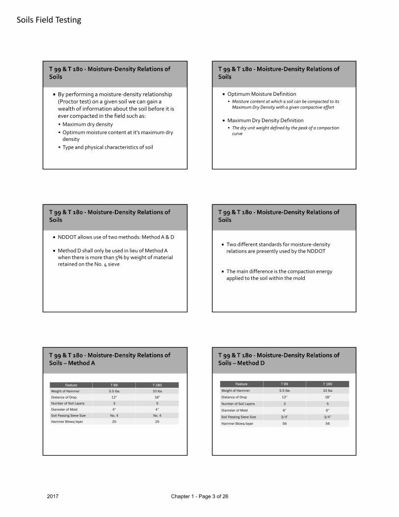
Feature T 99 T 180
Weight of Hammer 5.5 lbs 10 lbs
Distance of Drop 12” 18”
Number of Soil Layers 3 5
Diameter of Mold 4” 4”
Soil Passing Sieve Size No. 4 No. 4
Hammer Blows/layer 25 25
Feature T 99 T 180
Weight of Hammer 5.5 lbs 10 lbs
Distance of Drop 12” 18”
Number of Soil Layers 3 5
Diameter of Mold 6” 6”
Soil Passing Sieve Size 3/4” 3/4”
Hammer Blows/layer 56 56
2017 Chapter 1 - Page 3 of 26

Soils Field Testing
Sample Size Required
Test Method A Method D
One Point 7 lbs 25 lbs
Multi Point 35 lbs 125 lbs
• Procedures
• Method A or D
• T‐99 or T‐180
If soil is damp, dry in air or drying apparatus not exceeding 140 degrees F
Break up soil chunks so can be passed thru No. 4sieve
Discard any material retained on No. 4 sieve
Continue to dry mass of soil down until near or completely dry
Procedure
Divide sample into 5 individual samples (7 lb)
Add water to 1st sample to approx. 4 percentage points below optimum
Mix remaining samples as sample one increasing water by 2.5% or approx. (60 ml) for each point
Allow samples to cure for at least 12 hours
Weigh empty mold minus collar and base plate and record to nearest 0.01 lbs. Record on SFN 10063
Assemble mold, collar, and base plate and place on rigid/stable foundation
Add sufficient material to the mold to produce a compacted layer of approx. 1¾“ for T 99 or 1” for T 180.
Lightly tamp the soil until it is no longer loose or fluffy
Soil compacted with 25 evenly distributed blows
2017 Chapter 1 - Page 4 of 26

Soils Field Testing
After each layer trim any soil along the mold walls and distribute on top of compacted layer
Keep manual hammer perpendicular to base of mold and lift to it’s maximum position
Repeat procedure for each lift T‐99 3 liftsT‐180 5 lifts
Final layer should be just over the top of mold
After the last layer carefully remove collar by rotating it first to break the bond between it and soil before lifting off
Trim soil level with top of mold using a straightedge
After trimming clean off outside of mold. Remove from base plate
Weigh mold and wet soil and record to nearest 0.01 lbs
Subtract weight of mold by weight of the mold + wet soil and divide by volume of mold (1/30 Ft)
Record as wet density in lbs/cubic ft
Wet wt. of soil = (wt. of mold + soil) – wt. of mold
Wet density (pcf) = wet wt. of soil ÷ vol. of mold
Extrude from mold and collect a sample for water content determination
Slice soil specimen vertically through center
Moisture sample removed from one cut face over full length of inside of soil cylinder
Approx. 100 grams of wet soil
Place moisture sample in container, cover, and weigh
Record weight of wet soil to nearest 0.1 gram
Dry to constant weight as per T 265
Calculate moisture content to nearest 0.1%
2017 Chapter 1 - Page 5 of 26

Soils Field Testing
Compute and record Dry Density to nearest 0.1 pcf
Dry Density, (pcf) = (wet density x 100)/(100 + % moisture)
Repeat process for each point
Process continued until wet density decreases or stabilizes
Moisture content and dry density calculated for each sample
Graph data on cross‐ruled area on form SFN 10063
Dry density plotted on vertical (y) axis
Moisture content plotted on horizontal (x) axis
After points are plotted draw a smooth flowing curve through the plotted points
From peak of curve select Maximum Dry Density to record to nearest 1 lbs/cu. ft.
From peak of curve move vertically down and select Optimum Moisture and record to nearest 0.1%
Max dry density
Optimum moisture
2017 Chapter 1 - Page 6 of 26
Soils Field Testing
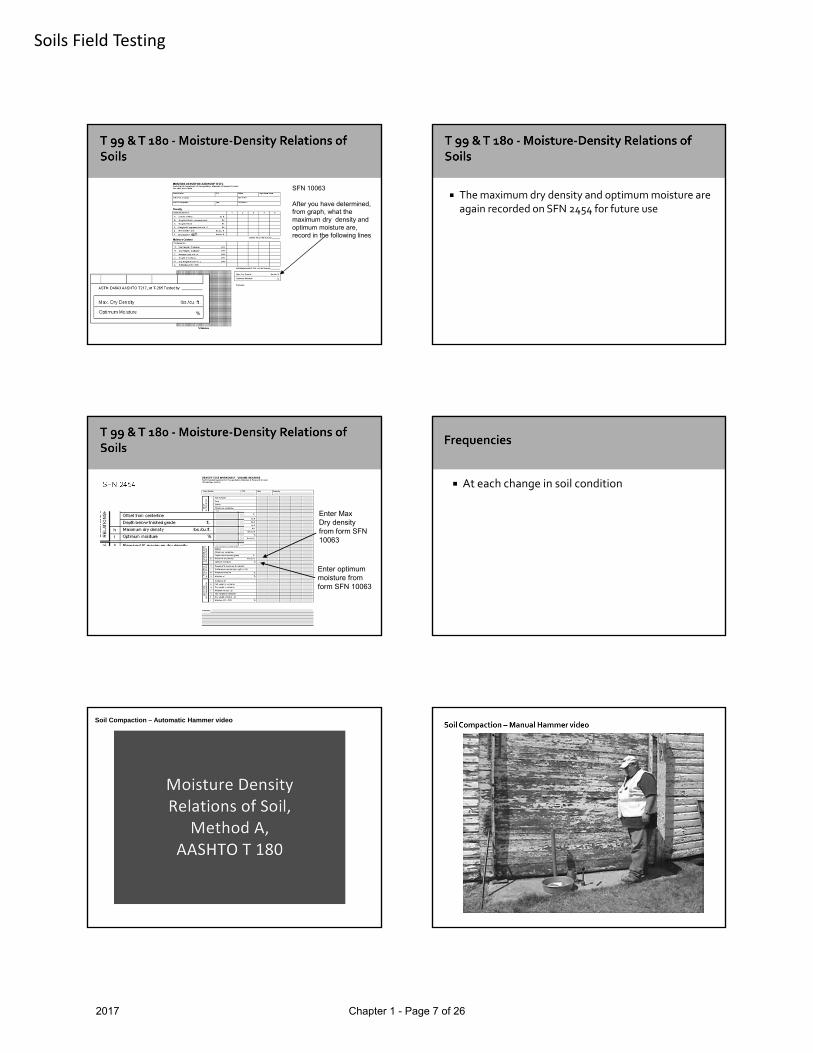
SFN 10063
After you have determined, from graph, what the maximum dry density and optimum moisture are, record in the following lines
The maximum dry density and optimum moisture are again recorded on SFN 2454 for future use
Enter MaxDry densityfrom form SFN 10063
Enter optimummoisture from form SFN 10063
SFN 2454 At each change in soil condition
Soil Compaction – Automatic Hammer video
2017 Chapter 1 - Page 7 of 26
Soils Field Testing
The NDDOT has analyzed many moisture‐density relationship curves and has found the curves follow certain patterns
From this analysis, typical moisture‐density relationship curves have been established and printed
Compacting one specimen as was done for first specimen of 5‐point proctor test
Determining the specimen’s dry density and moisture content
Follow curve (that point lies on) to highest point of curve, which indicates maximum dry density and optimum moisture content.
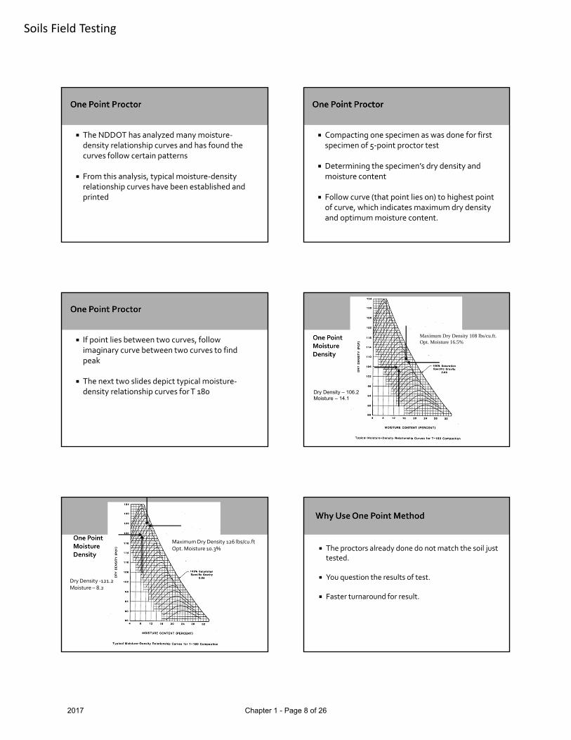
If point lies between two curves, follow imaginary curve between two curves to find peak
The next two slides depict typical moisture‐density relationship curves for T 180
Maximum Dry Density 108 lbs/cu.ft.Opt. Moisture 16.5%
Dry Density – 106.2Moisture – 14.1
Maximum Dry Density 126 lbs/cu.ftOpt. Moisture 10.3%
Dry Density ‐121.2Moisture – 8.2
The proctors already done do not match the soil just tested.
You question the results of test.
Faster turnaround for result.
2017 Chapter 1 - Page 8 of 26

Soils Field Testing
• Moisture level must be slightly drier than optimum and must fall to left of curve data
• One points are not recommended for granular material
• Use SFN 10063 and only one column but note on top “One Point Test”
• It will be assigned a test number also
Embankment Construction
Section 203.04 E.2
2. Compaction Control, Type A.
Construct all fills, excluding rock fills, with moisture and density controls. Place embankment in lifts not to exceed 12 inches of loose material.
Manipulate substandard areas by working the soil until the specified density and uniform moisture content are achieved.
Embankment Construction, continued
Compact material as specified in Section 203.04 E.2.a, “ND T 180” unless the contract specifies otherwise.
a. ND T 180.
Compact material to at least 90 percent of the maximum dry density with a moisture content no less than the optimum moisture and no more than 5.0 percentage points above the optimum moisture. The Engineer will determine the maximum dry density and optimum moisture content as specifi ed in ND T 180.
2017 Chapter 1 - Page 9 of 26

Soils Field Testing
b. ND T 99.Compact material to at least 95 percent of the maximum dry density with moisture content no less than 4.0 percentage points below the optimum moisture, and no more than 5.0 percentage points above the optimum moisture. The Engineer will determine the maximum dry density and optimum moisture content as specified in ND T 99.
714.04 A.7 Compaction Control for Aggregate.
Compact aggregate according to Section 203.04 E.2, “Compaction Control, Type A” The moisture content of the aggregate at the time of compaction shall be not less than 2.0 percentage points below, nor more than 3.0 percentage points above the optimum moisture content.
714.04 A.8 Compaction for Control Non‐Aggregate Material
If Common Excavation Type A is specified, follow the compaction requirements in Section 203.04 E.2, “Compaction Control, Type A.” If Common Excavation Type B is specified, follow the compaction requirements in Section 203.04 E.3, “Compaction Control, Type B.” Use a maximum lift thickness of 6 inches.
Determines total moisture content of soil, by removing all moisture from sample.
Drying Oven is heat source used for T 265
Weigh empty container including cover and record tare weight
Determine sample size needed from table in T 265
Cover to avoid moisture loss and weigh to the nearest 0.1 gram (wet weight)
Remove cover and place in oven at 230 +/‐ 9ºF (110 +/‐ 5ºC)
2017 Chapter 1 - Page 10 of 26

Soils Field Testing
Dry to constant weight or overnight (15 or 16 hours)
Allow sample to cool before placing on balance
Weigh the sample with cover and record as dry weight.
Calculate moisture to nearest 0.1%
Calculate % moisture as follows:
A=[(B‐C)/(C‐D)] x 100A = % moistureB = Mass of original sample and containerC = Mass of dry sample and containerD = Mass of container
Typical containers used in oven drying.
What if sample is not allowed to dry overnight?
Place sample in oven for specified period.
Remove from oven, cover, and allow to cool.
Weigh and record.
Repeat process until two successive readings show a constant weight.
Constant Weight ‐When further drying will cause less than 0.1% additional loss in mass when weighed at specified interval
Intervals
T 265 ‐Oven Drying –One Hour
The rubber balloon test utilizes a graduated glass cylinder filled with water
An assembly for applying air pressure
A balloon attached to the cylinder.
2017 Chapter 1 - Page 11 of 26

Soils Field Testing
Air pressure is forced into the cylinder and forces the water filled balloon out of the cylinder and into the test hole.
Pressure continues to be applied until water filled balloon completely fills test hole
The water (volume) displaced from cylinder as test hole is being filled is read directly from graduated cylinder.
All information is recorded on SFN 2454
Record the balloon volume readings to 0.00000 cu. Ft.
Choose your spot, remove loose material, and level the test area
Secure the base plate and fasten down
Place volume measure on base plate for initial reading
Using hand pump, while holding down on measure, force water into the balloon until resistance is felt
Apply calibrated pressure and note reading on glass cylinder. Record reading on State Form 2454
Apply calibrated pressure and note reading on glass cylinder
This is your initial reading. Record on SFN 2454
Remove the vessel from the base plate while taking note where vessel is aligned with the plate
2017 Chapter 1 - Page 12 of 26

Soils Field Testing
Dig a hole with the auger, trowel, or other tools
Test hole must be approx. 4” wide and 5” deep
Carefully remove the soil and do not lose any material from the hole (also remove soil from tools and base plate)
Collect soil in a tarred container with a cover
Put vessel back on base plate at the previous mark
Pump balloon down into test hole and apply calibrated pressure
Read and record final reading
Volume of test hole is determined by as follows:
Volume of Hole = Final Reading – Initial Reading
2017 Chapter 1 - Page 13 of 26

Soils Field Testing
The soil removed is weighed
Calculate wet density of the soil as follows:
Wet Density = Wet weight of Soils/Volume of hole
A moisture test is ran using reserved material and dry density is computed as follows:
Dry Density = (Wet Den. x 100)/(100 + % moisture)
Record the results on SFN 2454
The ratio between tested density and proctor density indicates the percent of compaction
Record results on SFN 2454
Report Dry Density to the nearest 0.1 lbs/cu. ft
2017 Chapter 1 - Page 14 of 26
Soils Field Testing
Excavation Embankment
1 test per lift per 1500 ft. of roadway
Reshape Roadway – Subgrade Prep – Stabilized Subgrade
1 test per lift per 1500 ft. of roadway
Density of Soil In‐Place ‐Video
The “Speedy Moisture Test” is used to determine moisture content of fine grained soils in the field
Advantage: Moisture content can be determined in remote area where there may be no electrical power and results can be obtained quickly
Use care when performing this test and working with the calcium chloride reagent
The reagent has an expiration date and should be verified before using
Depending on manufacturer, some models use 20 grams of soil and others use 26 grams for sample size
Instructions may tell you to put reactant in body, others in the cap or cover
Either method is fine as long as soil and reagent are not mixed before securing cover to body
Make sure body of tester is free of residue from previous test
Place steel balls in the body of tester
Take 3 – 5 full measures of reagent and place in body of tester
2017 Chapter 1 - Page 15 of 26
Soils Field Testing
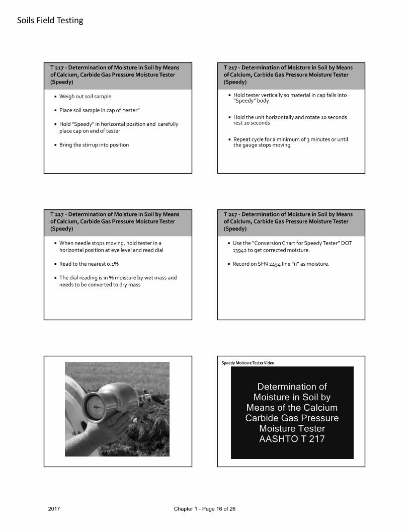
Weigh out soil sample
Place soil sample in cap of tester”
Hold “Speedy” in horizontal position and carefully place cap on end of tester
Bring the stirrup into position
Hold tester vertically so material in cap falls into “Speedy” body
Hold the unit horizontally and rotate 10 seconds rest 20 seconds
Repeat cycle for a minimum of 3 minutes or until the gauge stops moving
When needle stops moving, hold tester in a horizontal position at eye level and read dial
Read to the nearest 0.1%
The dial reading is in % moisture by wet mass and needs to be converted to dry mass
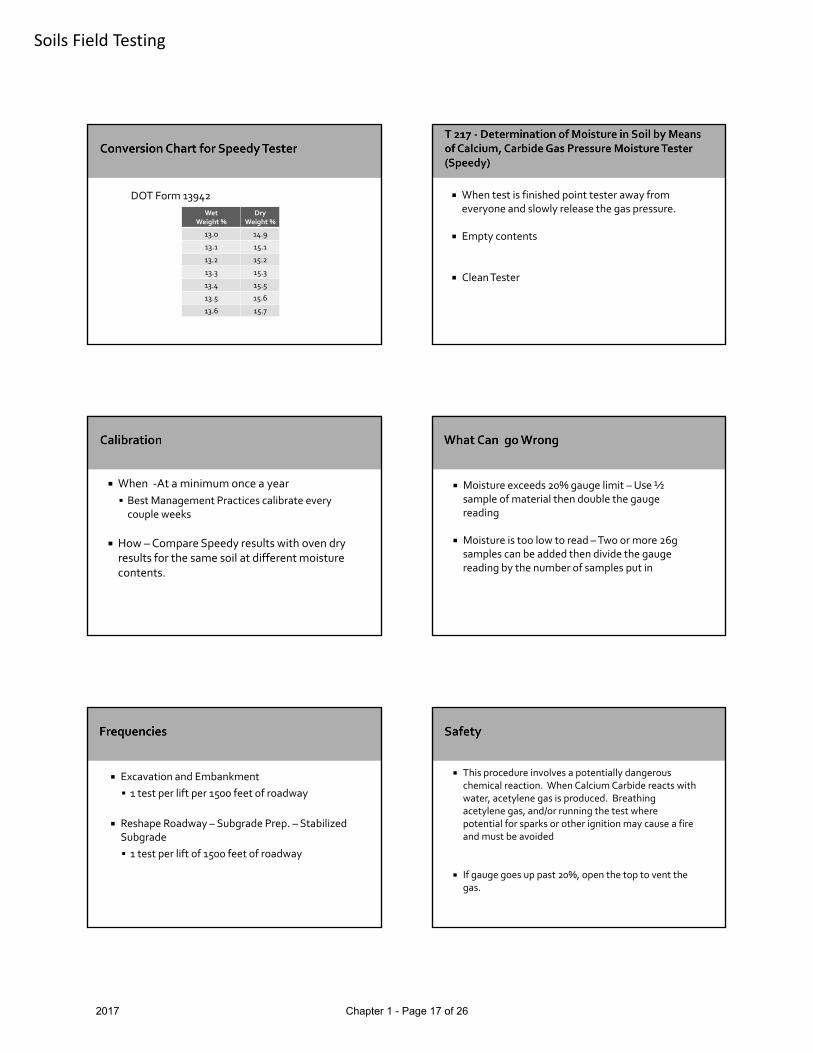
Use the “Conversion Chart for Speedy Tester” DOT 13942 to get corrected moisture.
Record on SFN 2454 line “n” as moisture.
2017 Chapter 1 - Page 16 of 26
Soils Field Testing
Wet Weight %
Dry Weight %
13.0 14.9
13.1 15.1
13.2 15.2
13.3 15.3
13.4 15.5
13.5 15.6
13.6 15.7
DOT Form 13942 When test is finished point tester away from everyone and slowly release the gas pressure.
Empty contents
Clean Tester
When ‐At a minimum once a year
Best Management Practices calibrate every couple weeks
How –Compare Speedy results with oven dry results for the same soil at different moisture contents.
Moisture exceeds 20% gauge limit –Use ½ sample of material then double the gauge reading
Moisture is too low to read –Two or more 26g samples can be added then divide the gauge reading by the number of samples put in
Excavation and Embankment
1 test per lift per 1500 feet of roadway
Reshape Roadway – Subgrade Prep. – Stabilized Subgrade
1 test per lift of 1500 feet of roadway
This procedure involves a potentially dangerous chemical reaction. When Calcium Carbide reacts with water, acetylene gas is produced. Breathing acetylene gas, and/or running the test where potential for sparks or other ignition may cause a fire and must be avoided
If gauge goes up past 20%, open the top to vent the gas.
2017 Chapter 1 - Page 17 of 26

Soils Field Testing
Scope
This method covers determination of in‐place density of compacted soil or soil‐aggregate mixtures.
The in‐place dry density is expressed as a percentage of soils maximum dry density and can be compared to specification requirements
Items to be discussed
Equipment Preparation
▪ Filling the apparatus
▪ Determining the mass of sand required to fill the funnel and base plate (Cone Correction)
▪ Determining the bulk density of sand (Ds)
Procedures
Calculations
Calibration
• Filling the apparatus
Place upright on level surface, close valve and fill funnel with sand
Open valve! Keep funnel at least half full with sand
When sand stops flowing, close valve sharply and empty excess sand
Determine and record mass of apparatus filled with sand (m1)
Cone Correction [Cc]
Place base plate on level surface. Invert sand cone and seat funnel on base plate
Open valve! Allow sand to flow until sand stops flowing
Close valve! Remove apparatus and determine mass of apparatus and remaining sand (m2)
Cone Correction Continued;
Mass of sand required to fill cone and base plate [Cc] is calculated by Cc = m1 – m2
Where: Cc = Cone Correction
m1 = Mass of apparatus filled with sand
m2 = Mass of apparatus filled with remaining sand
Complete all calculations on SFN 59724
Determination of bulk density of sand (DB)
Materials and Research has determined that (DB) equals 95 lbs/cubic foot for a given source of sand
If the sand source should change it would require that a new bulk density be determined.
2017 Chapter 1 - Page 18 of 26

Soils Field Testing
Fill apparatus with sand and record total mass
Select spot and level
Place base plate over level area and fasten down
Dig a test hole
Place excavated material into moisture tight container
Max Particle Size MinTest Hole Volume Min Size For Moisture
No. 4 0.025 cubic feet 100 g
½” 0.050 cubic feet 250 g
1’ 0.075 cubic feet 500 g
2” 0.100 cubic feet 1000 g
Place apparatus on base plate and open valve
After sand has stopped flowing close valve
Remove apparatus
Record the final mass
Weigh the wet material removed to the nearest 0.01 lb. and record
Use a representative portion of soil for moisture determination
Moisture can be determined by use of T 265 (oven method) or D 4643 (Microwave method)
Calculated to nearest 0.1%
2017 Chapter 1 - Page 19 of 26

Soils Field Testing
Complete Calculations on SFN 59725
Calculate in ‐ place density to the nearest 0.1 lbs/cubic feet
Complete calculations as follows:
(VH) Volume of Test Hole = (Initial Mass ‐ Final Mass ‐CC)/DB
Calculate the volume of test hole to the nearest 0.0001 ft3.
(MDS) Dry Mass of Material removed from test hole = (Moist Mass removed from test hole/ (1 + (% moisture /100))
Calculations continued:
Calculate dry mass of material to the nearest 0.01 lbs.
(DD) Dry Density = MDS/VH
Calculate in‐place dry density to the nearest 0.1 lbs/ft3.
Sand Cone video
All new devices should be calibrated prior to use
A calibration check should be performed annually as a minimum, or whenever damage or repair occurs.
Minimum power rating of 700 watts
Proper sample size
Use a heat sink
Set power on defrost
Use a microwave safe dish
2017 Chapter 1 - Page 20 of 26

Soils Field Testing
Heat sink, microwave safe dish, and spatula.
Stir with spatula or glass rod between heating cycles
Initial drying time of 3 minutes; 1 minute cycles thereafter
Repeat process until “Constant Weight” is achieved
Soils high in moisture and contain a large portion of clay take longer times to dry
Initial heating time for this type of soil may be 12 minutes.
Reduce cohesive samples to ¼” particles to speed drying
Calculate and record to 0.1%
A= [(B –C)/(C‐D)] x 100
A = Percent moisture
B = Mass of original (wet) sample, and containerC = Mass of dry sample, and containerD = Mass of container
• Scope
The method describes a procedure for adjusting densities of soil and soil‐aggregates to compensate for differing percentages of oversize particles retained on the No. 4 sieve. Therefore a correction to Method A (moisture‐density relation test) is required for the oversize removed
Scope
This shall be applied to soil‐aggregates which contain more than 5% by weight of oversize
If there is over 40% oversize another method may be required
2017 Chapter 1 - Page 21 of 26

Soils Field Testing
Sign
Date
If any corrections or change are made –sign/date – or make notation on electronic forms
A number of different soil types may be encountered
Each soil type may require different handling and/ or compaction techniques
The compaction Inspector/Tester must be alert to changes from one type of soil to another
The optimum density and moisture content used may well change and additional lab work will be required
Every lift must be compacted to the required density before the next lift is placed
Enough tests must be taken to insure a passing uniform grade
The tests will be taken at various locations on the fill to insure uniformity
It is good practice to have a proctor test available for each type of soil.
2017 Chapter 1 - Page 22 of 26
Soils Field Testing
Principle duty is to take compaction and moisture tests and compare results to the proctor
Determine location of and offset of compaction tests
Keep Engineer or Grade Inspector informed of test results at all times
Alert to changes in soil
Familiar with project plans and specifications
Have good lines of communication
Safety
Keep organized records
You may be required to conduct additional tests whenever you encounter unsatisfactory conditionssuch as:
Spongy surfaces
Equipment working unusually hard
Appreciable changes in soil color and textures
If test results fall just short of specifications inform the Contractor that:
The test failed
The inspector should tell the Contractoronly why the test failed, not what to do or how to correct it
If test results are noticeably short of
specifications, you should:
Perform a check test
Inspect the testing equipment
If the check test results are close to the required maximum density and optimum moisture
You are sure of your equipment and procedures
A visual observation of the material leads you to believe that the maximum density and optimum moisture should have been obtained then:
Perform a one‐point proctor
2017 Chapter 1 - Page 23 of 26

Soils Field Testing
Do not permit any lifts to be placed over failing lifts
Frequent compaction tests should be performed at beginning of project
This will force the Contractor to develop and maintain a uniform operation
Locations of test sites are critical
If the test results conform, at these locations, the rest of the earthwork is assumed to conform, too
To help determine representative test locations, we use a table of Random Numbers
A Random Number has no pattern or sequence in which they occur
As an Inspector, you should let the Contractor know that random numbers are being used
Random Numbers will help you schedule locations of tests ahead of time
The Contractor should not know where tests will be taken
2017 Chapter 1 - Page 24 of 26

Soils Field Testing
To locate a test site, you will need a longitudinal coordinate and a lateral coordinate. The longitudinal coordinate is the distance from the end of the test area, and the lateral coordinate is the distance from the edge of the test area
fLongitudinal Coord. Test Site
Lateral Coord.
BeginTest Area
EndTestArea
A sample table of random numbers is shown below A table of Random numbers is located in your Field Sampling and Testing Manual
0.39 0.29 0.26 0.22
0.42 0.82 0.65 0.28
0.33 0.08 0.42 0.55
0.040.12
0.430.17
0.450.52
0.460.89
First determine length and width of test area
Point to a block of numbers on the Random Numbers Table
Use first line of numbers as multipliers for length and second line of numbers as multipliers for width
Two test sites are needed in a test area 1,000 feet long and 40 feet wide
A block of numbers is randomly selected from the previous Table of Random Numbers
For this example we will use the upper right block.
The first row of numbers in this block can be used as multipliers for the test area lengths
0.78 0.67 0.25 0.42
0.39 0.29 0.26 0.22
0.42 0.82 0.65 0.28
0.33 0.08 0.42 0.55
0.040.12
0.430.17
0.450.52
0.460.89
The second row of numbers in this block can be used as multipliers for the test area widths
0.78 0.67 0.25 0.42
0.39 0.29 0.26 0.22
0.42 0.82 0.65 0.28
0.33 0.08 0.42 0.55
0.040.12
0.430.17
0.450.52
0.460.89
2017 Chapter 1 - Page 25 of 26
Soils Field Testing
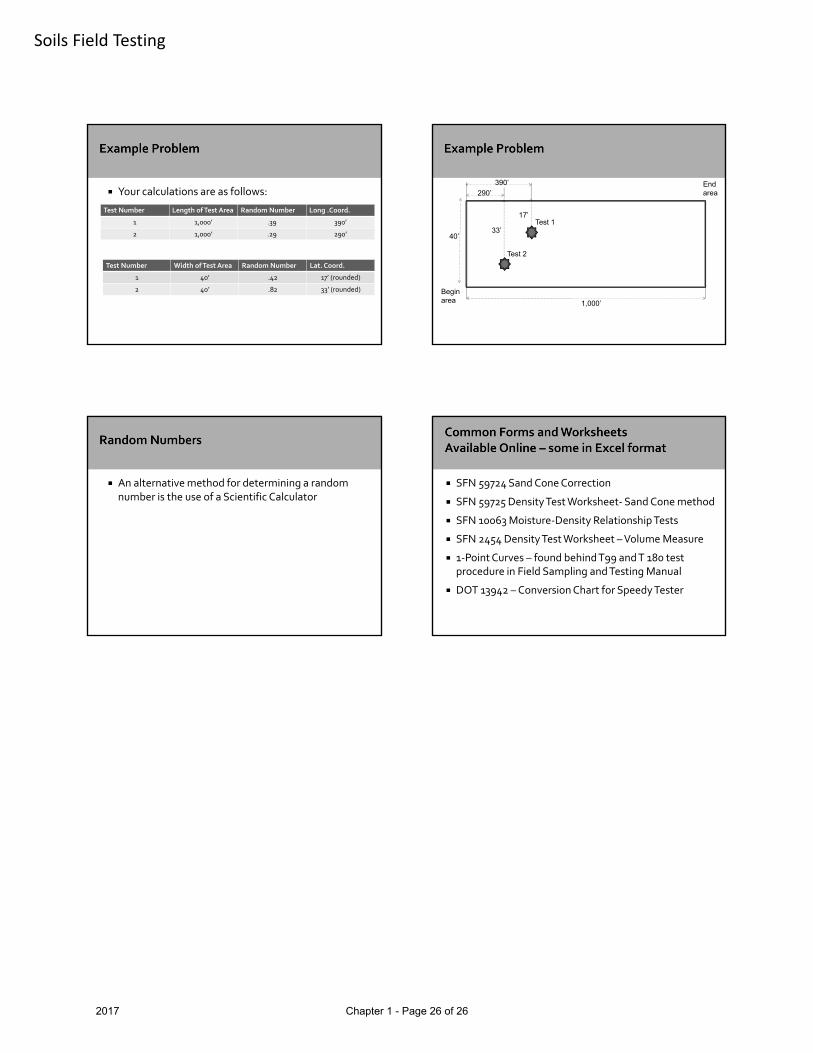
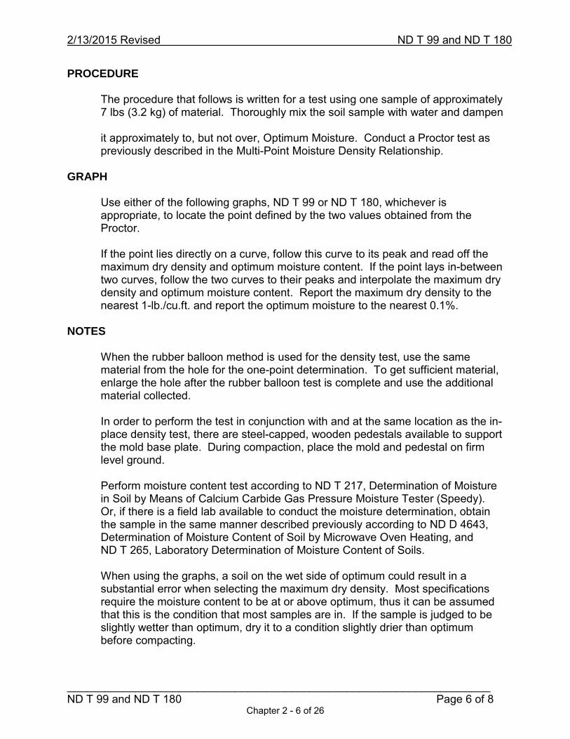
Your calculations are as follows:
Test Number Length of Test Area Random Number Long .Coord.
1 1,000’ .39 390’
2 1,000’ .29 290’
Test Number Width of Test Area Random Number Lat. Coord.
1 40’ .42 17’ (rounded)
2 40’ .82 33’ (rounded)
40’
290’
390’
1,000’
Test 1
Test 2
33’
17’
Beginarea
Endarea
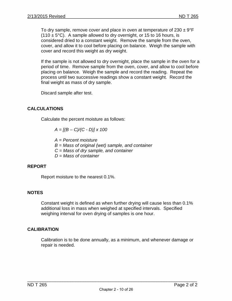
An alternative method for determining a random number is the use of a Scientific Calculator
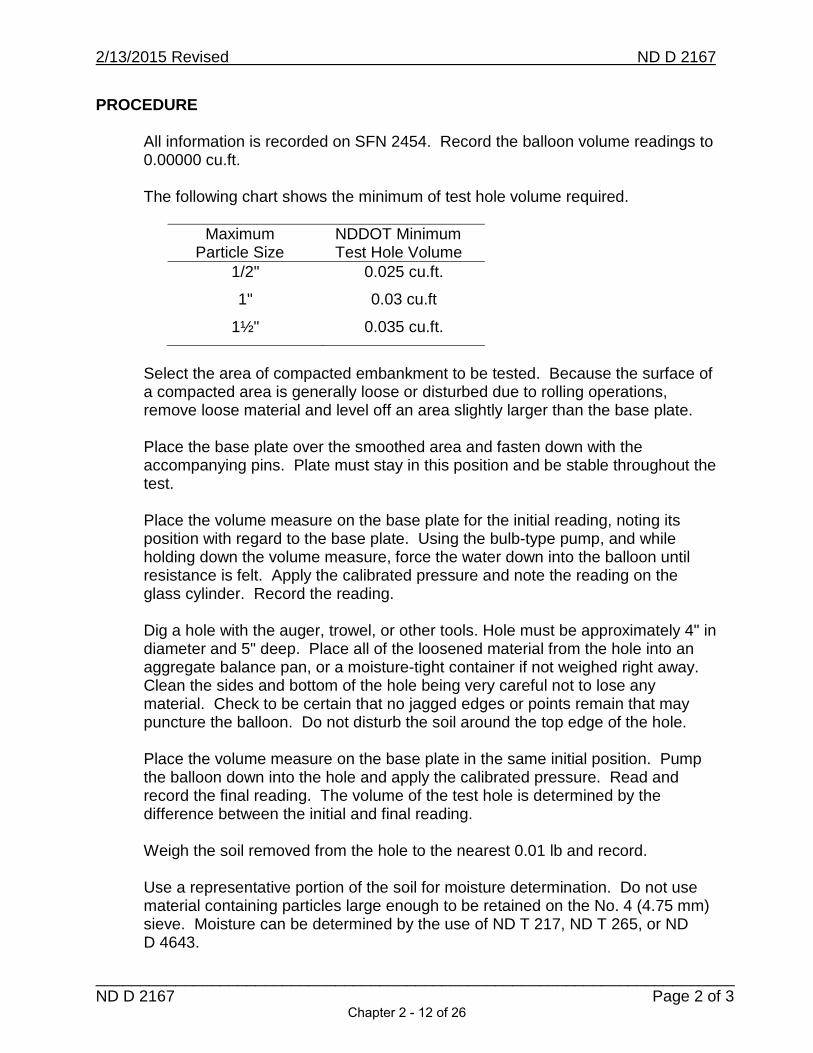
SFN 59724 Sand Cone Correction
SFN 59725 Density Test Worksheet‐Sand Cone method
SFN 10063 Moisture‐Density Relationship Tests
SFN 2454 Density Test Worksheet –Volume Measure
1‐Point Curves – found behind T99 and T 180 test procedure in Field Sampling and Testing Manual
DOT 13942 –Conversion Chart for Speedy Tester
2017 Chapter 1 - Page 26 of 26

Test Procedures
Chapter 2 Page T 99 and T 180 – Moisture-Density Relations of Soils ................................................... 1 T 265 – Laboratory Determination of Moisture Content of Soils ................................... 9 D 2167 – Density And Unit Weight Of Soil In Place By The Rubber-Balloon Method .................................................................... 11 T 217 – Determination of Moisture in Soil by Means of Calcium Carbide Gas Pressure Tester (Speedy) ........................................... 15 T 191 – Density In-Place by the Sand Cone Method ................................................... 19 D 4643 – Microwave Method of Drying Soils ............................................................... 23 T 224 – Correction for Coarse Particles in the Soil Compaction Test .......................... 25


ND T 99 AND ND T 180MOISTURE-DENSITY RELATIONS OF SOILS
SCOPE
METHOD A
Chapter 2 - 1 of 26

METHOD D
REFERENCED DOCUMENTS
APPARATUS
SAMPLE SIZE
Method A
Chapter 2 - 2 of 26

Method D
PROCEDURE
Multi-Point Moisture Density Relationship - Mechanical and Manual
Chapter 2 - 3 of 26

Wet Weight of Soil = Weight of Mold + Soil – Weight of Mold
Wet Density, pcf = Wet Weight of Soil/Volume of Mold
Dry Density, pcf = (Wet Density X 100)/(100 + % Moisture)
Chapter 2 - 4 of 26

GRAPH
NOTES
CALIBRATION
One-Point Moisture Density Relationship with Typical Moisture-Density Curve Method
Chapter 2 - 5 of 26
PROCEDURE
GRAPH
NOTES
Chapter 2 - 6 of 26

114
110
106
102
98
94
90
86
82
78
74
704 8 12 16 20 24 28 32 36 38
Moisture Content PercentTypical Moisture-Density Relationship Curves for T 99 ompaction
DryDensityPCF
100% SaturationSpecific Gravity
2.65
Chapter 2 - 7 of 26

100% SaturationSpecific Gravity
2.65
134
130
126
122
118
114
110
106
102
98
94
90
864 8 12 16 20
Moisture Content Percent
24 28 32
Typical Moisture-Density Relationship Curves for T-180 Compaction
DryDensityPCF
2/13/2015 Revised ND T 99 and ND T 180
______________________________________________________________________ ND T 99 and ND T 180
Page 8 of 8Chapter 2 - 8 of 26

2/13/2015 Revised ND T 265
___________________________________________________________________ND T 265 Page 1 of 2
ND T 265 - LABORATORY DETERMINATION OFMOISTURE CONTENT OF SOILS
Conduct this procedure according to ND T 265.
Consult the current edition of AASHTO for procedure in its entirety andequipment specification details.
SCOPE
This procedure is used to determine the total moisture content of a soil. The soil is dried to remove all free moisture. This test measures the weight of the moisture removed from the soil.
APPARATUS
OvenBalanceSample containers with cover
PROCEDURE
Record all weights to the nearest 0.1 g or 0.1%.
Weigh a clean, dry, and empty container including the cover and record as tare weight.
Determine sample size needed from the table below. The sample obtained must be representative of the soil.
Maximum Particle Size Minimum Mass of Sample
No. 40 (0.425 mm) sieve 10 g
No. 4 (4.75 mm) sieve 100 g
1/2" (12.5 mm) 300 g
1" (25.0 mm) 500 g
2" (50 mm) 1000 g
Place sample in container and cover to prevent moisture loss. Weigh sample and record as mass of original sample.
Chapter 2 - 9 of 26
2/13/2015 Revised ND T 265
___________________________________________________________________ND T 265 Page 2 of 2
To dry sample, remove cover and place in oven at temperature of 230 ± 9°F (110 ± 5°C). A sample allowed to dry overnight, or 15 to 16 hours, is considered dried to a constant weight. Remove the sample from the oven, cover, and allow it to cool before placing on balance. Weigh the sample with cover and record this weight as dry weight.
If the sample is not allowed to dry overnight, place the sample in the oven for a period of time. Remove sample from the oven, cover, and allow to cool before placing on balance. Weigh the sample and record the reading. Repeat the process until two successive readings show a constant weight. Record the final weight as mass of dry sample.
Discard sample after test.
CALCULATIONS
Calculate the percent moisture as follows:
A = [(B – C)/(C - D)] x 100
A = Percent moistureB = Mass of original (wet) sample, and containerC = Mass of dry sample, and containerD = Mass of container
REPORT
Report moisture to the nearest 0.1%.
NOTES
Constant weight is defined as when further drying will cause less than 0.1%additional loss in mass when weighed at specified intervals. Specified weighing interval for oven drying of samples is one hour.
CALIBRATION
Calibration is to be done annually, as a minimum, and whenever damage or repair is needed.
Chapter 2 - 10 of 26

2/13/2015 Revised ND D 2167
________________________________________________________________________ND D 2167 Page 1 of 3
ND D 2167 - DENSITY AND UNIT WEIGHT OF SOIL IN PLACEBY THE RUBBER-BALLOON METHOD
Conduct this procedure according to ND D 2167.
The NDDOT modified the ASTM standard by decreasing the minimum requirement for test hole volume.
Consult the current edition of ASTM for procedure in its entirety and equipment specification details.
SCOPE
This method covers the determination of the in-place soil density of compacted or firmly bonded soil using a rubber-balloon apparatus.
Embankment compaction is controlled by requiring the density of each different soil, after compaction, be a specified minimum percentage of the maximum dry density. The maximum dry density is determined for each different soil on the project. When a particular soil is encountered in the excavation and transferred to and compacted in the embankment, it is tested by the method given in this section to determine its dry density. The in-place dry density is expressed as a percentage of the soils maximum dry density and can be compared to specification requirements.
REFERENCED DOCUMENTS
ND T 217 and AASHTO T 217, Determination of Moisture in Soil by Meansof Calcium Carbide Gas Pressure Moisture Tester (Speedy)
ND T 265 and AASHTO T 265, Laboratory Determination of MoistureContent of Soils
ND D 4643 and ASTM D 4643, Determination of Moisture Content of Soil bythe Microwave Oven Method
APPARATUS
Rubber-balloon apparatus and base plateBalance, readable to 0.01 lbsPins, shovel, trowel, spoon, hammer, and knifeAuger, 4" diameterAppropriate size container with lid
Chapter 2 - 11 of 26
2/13/2015 Revised ND D 2167
________________________________________________________________________ND D 2167 Page 2 of 3
PROCEDURE
All information is recorded on SFN 2454. Record the balloon volume readings to 0.00000 cu.ft.
The following chart shows the minimum of test hole volume required.
MaximumParticle Size
NDDOT MinimumTest Hole Volume
1/2"
1"
1½"
0.025 cu.ft.
0.03 cu.ft
0.035 cu.ft.
Select the area of compacted embankment to be tested. Because the surface of a compacted area is generally loose or disturbed due to rolling operations, remove loose material and level off an area slightly larger than the base plate.
Place the base plate over the smoothed area and fasten down with the accompanying pins. Plate must stay in this position and be stable throughout the test.
Place the volume measure on the base plate for the initial reading, noting its position with regard to the base plate. Using the bulb-type pump, and while holding down the volume measure, force the water down into the balloon until resistance is felt. Apply the calibrated pressure and note the reading on the glass cylinder. Record the reading.
Dig a hole with the auger, trowel, or other tools. Hole must be approximately 4" in diameter and 5" deep. Place all of the loosened material from the hole into an aggregate balance pan, or a moisture-tight container if not weighed right away. Clean the sides and bottom of the hole being very careful not to lose any material. Check to be certain that no jagged edges or points remain that may puncture the balloon. Do not disturb the soil around the top edge of the hole.
Place the volume measure on the base plate in the same initial position. Pump the balloon down into the hole and apply the calibrated pressure. Read and record the final reading. The volume of the test hole is determined by the difference between the initial and final reading.
Weigh the soil removed from the hole to the nearest 0.01 lb and record.
Use a representative portion of the soil for moisture determination. Do not use material containing particles large enough to be retained on the No. 4 (4.75 mm) sieve. Moisture can be determined by the use of ND T 217, ND T 265, or NDD 4643.
Chapter 2 - 12 of 26
2/13/2015 Revised ND D 2167
________________________________________________________________________ND D 2167 Page 3 of 3
CALCULATIONS
Complete calculations as follows:
Volume of Hole = Final Reading - Initial Reading
Wet Density = Wet Weight of Soil / Volume of Hole
Dry Density = (Wet Density x 100) / (100 + Percent Moisture)
REPORT
Report dry density to the nearest 0.1 lbs/cu.ft.
CALIBRATION
All new devices should be calibrated prior to being used. A calibration check should be performed annually as a minimum, or whenever damage or repair occurs.
Chapter 2 - 13 of 26

Chapter 2 - 14 of 26

2/13/2015 Revised ND T 217
___________________________________________________________________ND T 217 Page 1 of 3
ND T 217 - DETERMINATION OF MOISTURE IN SOIL BY MEANS OF CALCIUM CARBIDE GAS PRESSURE
MOISTURE TESTER (SPEEDY)
Conduct this procedure according to ND T 217.
The AASHO standard test procedure specifies for the moisture content to be recorded to the nearest whole number. The NDDOT modification specifies the moisture content to be recorded to the nearest 0.1.
Consult the current edition of AASHTO for procedure in its entirety and equipment specification details.
SCOPE
This test used to determine the moisture content of soils by means of a calcium carbide gas pressure moisture tester in the field. The tester is referred to as the “Speedy”. This method shall not be used for granular material having particles retained on the No. 4 (4.75 mm) sieve.
Use care when performing this test and working with the calcium chloride reagent. The reagent has an expiration date and should be verified before using. Tightly close reagent cans when not in use.
Use DOT 13942, “Conversion Chart for the Speedy Tester,” to convert the reading on the tester dial.
REFERENCED DOCUMENTS
AASHTO T 217, Determination of Moisture in Soil by Means of CalciumCarbide Gas Pressure Moisture Tester (Speedy)
ND T 265 and AASHTO T 265, Laboratory Determination of MoistureContent of Soils
APPARATUS
Calcium carbide pressure moisture tester, “Speedy,” which includes a balance, steel balls, and cleaning brush.
Calcium carbide reagent and scoop to measure reagent.
PROCEDURE
Instructions are written for a 20 to 26 g tester. There are various models of the “Speedy” in use with slight variations in instructions. Some models include 1.25"
Chapter 2 - 15 of 26

2/13/2015 Revised ND T 217
___________________________________________________________________ND T 217 Page 2 of 3
steel balls, others use 1" steel balls. Manufacturer’s instructions may tell you to put the reagent in the body, others the cap. Either method may be used as long as the soil and reagent are not mixed before securing the cover.
Read and follow ND T 217 and the manufacturer’s instructions to conduct this test.
The following describes the ND T 217 method for conducting the test.
Before beginning the test, verify the inside of the body and cap are free from residue of any previous test.
Place the steel balls into the body.
Take three full measures of reagent and place in body of vessel. For bulky materials, use three to five measures to ensure adequate coverage.
Measure your sample. The sample size needed is determined by the manufacturer of your tester.
Your tester kit may have an electronic balance or a beam balance. For a beam balance, lift into an upright position and add material to the pan. The correct amount of material is determined when the red markings on the balance and beam coincide.
Place the sample in the cover of the “Speedy”.
Hold the “Speedy” in a horizontal position and place the cover on the end. Bring the stirrup in position and tighten. This should be completed without the sample and reagent coming in contact with each other.
Hold vertically so that the material in the cap falls into the “Speedy” body.Return the instrument to a horizontal position, shake to break all lumps, and mix the soil and reagent. Shake with a rotating motion to put the steel balls into ‘orbit’ around the inside circumference. Rotate for 10 seconds, rest for 20 seconds. The rest time allows for dissipation of the heat generated by the chemical reaction. Continue this cycle for a minimum of 3 minutes.
When the needle stops moving, hold the instrument horizontal at eye level with the dial facing you. Read and record the dial reading to the nearest 0.1.
Hold tester away from your body. Point the directional release away from you and anyone else, then slowly release the pressure. Avoid breathing the fumes. Empty the contents and examine for lumps. If material contains lumps, repeat the test.
Chapter 2 - 16 of 26

2/13/2015 Revised ND T 217
___________________________________________________________________ND T 217 Page 3 of 3
Thoroughly clean the tester with the brush provided.
CALCULATIONS
The dial reading is percent moisture by wet mass and needs to be converted to dry mass using form DOT 13942.
REPORT
Report the percent moisture to the 0.1%.
NOTES
If the moisture content of the soil sample is greater than the ability for the gauge to read, run the test using a one-half size sample. The dial reading is multiplied by two and then converted to dry mass using DOT 13942.
CALIBRATION
Calibration is to be done annually as a minimum, and whenever damage or repair occurs. This can be accomplished by comparing the “Speedy” results to a sample oven-dried according to ND T 265. Calibration will result in verifying DOT 13942, “Conversion Chart for the Speedy Tester.”
Chapter 2 - 17 of 26

CONVERSION CHART FOR SPEEDY TESTERNorth Dakota Department of Transportation, Materials & ResearchDOT 13942 (Rev. 05-2000)
WETWT. %
DRYWT. %
WETWT. %
DRYWT. %
WETWT. %
DRYWT. %
WETWT. %
DRYWT. %
WETWT. %
DRYWT. %
1.0 - 1.01.1 - 1.11.2 - 1.21.3 - 1.31.4 - 1.41.5 - 1.51.6 - 1.61.7 - 1.71.8 - 1.81.9 - 1.92.0 - 2.02.1 - 2.12.2 - 2.22.3 - 2.42.4 - 2.52.5 - 2.62.6 - 2.72.7 - 2.82.8 - 2.92.9 - 2.93.0 - 3.13.1 - 3.23.2 - 3.33.3 - 3.43.4 - 3.53.5 - 3.63.6 - 3.73.7 - 3.83.8 - 4.03.9 - 4.14.0 - 4.24.1 - 4.34.2 - 4.44.3 - 4.54.4 - 4.64.5 - 4.74.6 - 4.84.7 - 4.94.8 - 5.04.9 - 5.25.0 - 5.35.1 - 5.45.2 - 5.55.3 - 5.65.4 - 5.75.5 - 5.85.6 - 5.95.7 - 6.05.8 - 6.25.9 - 6.36.0 - 6.46.1 - 6.56.2 - 6.66.3 - 6.76.4 - 6.86.5 - 7.06.6 - 7.16.7 - 7.26.8 - 7.36.9 - 7.4
7.0 - 7.5 7.1 - 7.6 7.2 - 7.7 7.3 - 7.9 7.4 - 8.0 7.5 - 8.1 7.6 - 8.2 7.7 - 8.3 7.8 - 8.5 7.9 - 8.6 8.0 - 8.7 8.1 - 8.8 8.2 - 8.9 8.3 - 9.1 8.4 - 9.2 8.5 - 9.3 8.6 - 9.4 8.7 - 9.5 8.8 - 9.6 8.9 - 9.8 9.0 - 9.9 9.1 - 10.0 9.2 - 10.1 9.3 - 10.3 9.4 - 10.4 9.5 - 10.5 9.6 - 10.6 9.7 - 10.7 9.8 - 10.9 9.9 - 11.010.0 - 11.110.1 - 11.210.2 - 11.410.3 - 11.510.4 - 11.610.5 - 11.710.6 - 11.910.7 - 12.010.8 - 12.110.9 - 12.211.0 - 12.311.1 - 12.511.2 - 12.611.3 - 12.711.4 - 12.911.5 - 13.011.6 - 13.111.7 - 13.311.8 - 13.411.9 - 13.512.0 - 13.612.1 - 13.812.2 - 13.912.3 - 14.012.4 - 14.212.5 - 14.312.6 - 14.412.7 - 14.512.8 - 14.712.9 - 14.8
13.0 - 14.913.1 - 15.113.2 - 15.213.3 - 15.313.4 - 15.513.5 - 15.613.6 - 15.713.7 - 15.913.8 - 16.013.9 - 16.114.0 - 16.314.1 - 16.414.2 - 16.614.3 - 16.714.4 - 16.814.5 - 17.014.6 - 17.114.7 - 17.214.8 - 17.414.9 - 17.515.0 - 17.615.1 - 17.815.2 - 17.915.3 - 18.115.4 - 18.215.5 - 18.315.6 - 18.515.7 - 18.615.8 - 18.815.9 - 18.916.0 - 19.016.1 - 19.216.2 - 19.316.3 - 19.516.4 - 19.616.5 - 19.816.6 - 19.916.7 - 20.016.8 - 20.216.9 - 20.317.0 - 20.517.1 - 20.617.2 - 20.817.3 - 20.917.4 - 21.117.5 - 21.217.6 - 21.417.7 - 21.517.8 - 21.717.9 - 21.818.0 - 22.018.1 - 22.118.2 - 22.218.3 - 22.418.4 - 22.518.5 - 22.718.6 - 22.918.7 - 23.018.8 - 23.218.9 - 23.3
19.0 - 23.519.1 - 23.719.2 - 23.819.3 - 23.919.4 -24.119.5 - 24.219.6 - 24.419.7 - 24.519.8 - 24.719.9 - 24.820.0 - 25.020.1 - 25.220.2 - 25.320.3 - 25.520.4 - 25.620.5 - 25.820.6 - 25.920.7 - 26.120.8 - 26.320.9 - 26.421.0 - 26.621.1 - 26.721.2 - 26.921.3 - 27.121.4 - 27.221.5 - 27.421.6 - 27.621.7 - 27.721.8 - 27.921.9 - 28.022.0 - 28.222.1 - 28.422.2 - 28.522.3 - 28.722.4 - 28.922.5 - 29.022.6 - 29.222.7 - 29.422.8 - 29.522.9 - 29.723.0 - 29.923.1 - 30.023.2 - 30.223.3 - 30.423.4 - 30.523.5 - 30.723.6 - 30.923.7 - 31.123.8 - 31.223.9 - 31.424.0 - 31.624.1 - 31.824.2 - 31.924.3 - 32.124.4 - 32.324.5 - 32.524.6 - 32.624.7 - 32.824.8 - 33.024.9 - 33.2
25.0 - 33.325.1 - 33.525.2 - 33.725.3 - 33.925.4 - 34.025.5 - 34.225.6 - 34.425.7 - 34.625.8 - 34.825.9 - 35.026.0 - 35.126.1 - 35.326.2 - 35.526.3 - 35.726.4 - 36.926.5 - 36.126.6 - 36.226.7 - 36.426.8 - 36.626.9 - 36.827.0 - 37.027.1 - 37.227.2 - 37.427.3 - 37.627.4 - 37.727.5 - 37.927.6 - 38.127.7 - 38.327.8 - 38.527.9 - 38.728.0 - 38.928.1 - 39.128.2 - 39.328.3 - 39.528.4 - 39.728.5 - 39.928.6 - 40.128.7 - 40.328.8 - 40.428.9 - 40.629.0 - 40.829.1 - 41.029.2 - 41.229.3 - 41.429.4 - 41.629.5 - 41.829.6 - 42.029.7 - 42.229.8 - 42.529.9 - 42.730.0 - 42.930.1 - 43.130.2 - 43.330.3 - 43.530.4 - 43.730.5 - 43.930.6 - 44.130.7 - 44.330.8 - 44.530.9 - 44.7
Chapter 2 - 18 of 26

2/13/2015 Revised ND T 191
ND T 191 Page 1 of 4
ND T 191 – DENSITY OF SOIL IN-PLACE BY THE SAND CONE METHOD
Conduct this procedure according to ND T 191.
Consult the current edition of AASHTO for procedure in its entirety and equipment specification details
SCOPE
This method covers the determination of the in-place density of compacted soil or soil-aggregate mixtures. The in-place dry density is expressed as a percentage of the soils maximum dry density and can be compared to specification requirements.
REFERENCED DOCUMENTS
AASHTO T 19, Bulk Density (“Unit Weight”) and Voids in AggregateAASHTO T 191, Density of Soil In-Place by the Sand Cone MethodND T 265 and AASHTO T 265, Laboratory Determination of Moisture
Content of Soils ASTM D 4643, Determination of Moisture Content of Soil by the Microwave
Oven Method
APPARATUS
Sand density apparatus and base plateClean, free-flowing sand consisting of -No.10 +No.200Balance, readable to 0.1 gramsPins, shovel, trowel, spoon, hammer, and knifeAuger, 4" diameterSealable container
EQUIPMENT PREPARATION
Filling the apparatus
1. Place the empty apparatus upright on a firm level surface, close the valve and fill the funnel with sand.
2. Open the valve and keep the funnel at least half full with sand during filling. When the sand stops flowing into the apparatus, close the valve sharply andempty the excess sand.
3. Determine and record the mass of the apparatus filled with sand (m1).
Chapter 2 - 19 of 26

2/13/2015 Revised ND T 191
ND T 191 Page 2 of 4
Determining the mass of sand required to fill the funnel and base plate (ConeCorrection)
1. Place the base plate on a clean, level, plane surface. Invert the sand cone filled with sand, and seat the funnel in the recess of the base plate.
2. Open the valve fully and allow the sand to flow until the sand stops flowing.
3. Close the valve sharply, remove the apparatus, and determine the mass of the apparatus and the remaining sand (m2).
4. The mass of sand required to fill the cone and base plate is calculated by the difference between the initial mass and final mass. Record this mass as the cone correction:
(Cc = m1 – m2).
Where:CC = Cone correctionm1 = Mass of the apparatus filled with sandm2 = Mass of the apparatus and remaining sand
Notes:
For each container/bag of sand there will be a unique cone correction and sand calibration factor. Each sand-cone and matched base plate will also have a set of unique cone corrections and bulk sand densities. If more than one sand-cone apparatus is available, the sand-cone and base plate should be marked and the associated correction/density factors recorded.
Vibration of the sand during any mass-volume determination may increase bulk density of the sand and decrease the accuracy of the determination. Appreciable time intervals between the bulk density determination of the sand and its use in the field may result in change in the bulk density caused by a change in the moisture content or effective gradation.
Determining the bulk density of sand (DB)
1. Replace the sand removed in the funnel determination according to the procedure for filling the apparatus, close the valve, and determine the mass of the apparatus and sand (m3).
2. Position the calibration container on a clean, level, plane surface. Place the base plate on the calibration container. Invert the apparatus and seat the funnel in the recess of the base plate.
3. Open the valve fully and keep open until the sand stops flowing.
Chapter 2 - 20 of 26

2/13/2015 Revised ND T 191
ND T 191 Page 3 of 4
4. Close the valve sharply, remove the apparatus and determine the remaining mass of the apparatus and sand (m4).
5. Calculate the mass of the sand needed to fill the container, funnel and baseplate. Subtract the final mass (Step 4), from the initial mass (Step 1).
6. The mass of the sand needed to fill the container only is determined by subtracting the mass of the cone correction (Step 4) from the total mass required to fill the container with the funnel and base plate (Step 5).
7. Determine the bulk density of the calibration sand (sand calibration factor). Divide the mass of the sand needed to fill the container (Step 6), by the volume of the calibration container as determined according to AASHTO T 19.
DB = (m3 – m4 – CC)/VC
Where:DB = Bulk density of the sand in g/cm3
m3 = Mass of the apparatus and sandm4 = Remaining mass of the apparatus and the sandCC = Cone correctionVC = Volume of the calibration container
8. Record this factor for future reference.
PROCEDURE
All information is recorded on SFN 59725 and SFN 59724.
Fill testing apparatus with sand and record the total mass.
Select the area of compacted lift to be tested. Because the surface of a compacted area is generally loose or disturbed due to compaction operations, remove loose material and level off an area slightly larger than the base plate.
Place the base plate over the smoothed area and fasten down with the accompanying pins. Plate must stay in this position and be stable throughout the test.
Dig a test hole within base plate opening, with the auger, trowel, or other tools.Soils that are granular require extreme care and may require the digging of a conical-shaped hole. Place all of the loosened material from the hole into an aggregate balance pan, or a moisture-tight container if not weighed right away.
Chapter 2 - 21 of 26

2/13/2015 Revised ND T 191
ND T 191 Page 4 of 4
Minimum Test Hole Volumes and Moisture Content SamplesBased on Maximum Size
MaximumParticle Size
Minimum Test Hole Volume
Minimum Sample Size for Moisture Content
No. 4 (4.75 mm) 0.025 ft3 100 g
1/2" (12.5 mm) 0.050 ft3 250 g
1" (25.0 mm) 0.075 ft3 500 g
2" (50.0 mm) 0.100 ft3 1000 g
Place testing apparatus on the base plate and open valve. After the sand has stopped flowing, close the valve; remove apparatus, and record final mass.
Weigh the wet soil or soil-aggregates removed from the hole to the nearest 0.01 lbs and record.
Use a representative portion of the soil for moisture determination. Do not use material containing particles large enough to be retained on the No. 4 (4.75 mm) sieve. Moisture can be determined by the use of ND T 265 or ND D 4643.Calculate moisture to nearest 0.1%.
CALCULATIONS
Complete calculations as follows:
(VH) Volume of Test Hole = (Initial Mass - Final Mass - CC)/DB
Calculate the volume of test hole to the nearest 0.0001 ft3.
(MDS) Dry Mass of Material removed from test hole = (Moist Mass removed from test hole/[1 + (% moisture /100)]
Calculate dry mass of material to the nearest 0.01 lbs.
(DD) Dry Density = MDS/VH
Calculate in-place dry density to the nearest 0.1 lbs/ft3.
CALIBRATION
All new devices should be calibrated prior to being used. A calibration check should be performed annually as a minimum, or whenever damage or repair occurs.
Chapter 2 - 22 of 26
2/13/2015 Revised ND D 4643
___________________________________________________________________ND D 4643 Page 1 of 2
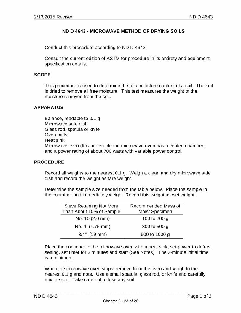
ND D 4643 - MICROWAVE METHOD OF DRYING SOILS
Conduct this procedure according to ND D 4643.
Consult the current edition of ASTM for procedure in its entirety and equipment specification details.
SCOPE
This procedure is used to determine the total moisture content of a soil. The soil is dried to remove all free moisture. This test measures the weight of the moisture removed from the soil.
APPARATUS
Balance, readable to 0.1 gMicrowave safe dishGlass rod, spatula or knifeOven mittsHeat sinkMicrowave oven (It is preferable the microwave oven has a vented chamber,and a power rating of about 700 watts with variable power control.
PROCEDURE
Record all weights to the nearest 0.1 g. Weigh a clean and dry microwave safe dish and record the weight as tare weight.
Determine the sample size needed from the table below. Place the sample in the container and immediately weigh. Record this weight as wet weight.
Sieve Retaining Not More Than About 10% of Sample
Recommended Mass of Moist Specimen
No. 10 (2.0 mm) 100 to 200 g
No. 4 (4.75 mm) 300 to 500 g
3/4" (19 mm) 500 to 1000 g
Place the container in the microwave oven with a heat sink, set power to defrost setting, set timer for 3 minutes and start (See Notes). The 3-minute initial time is a minimum.
When the microwave oven stops, remove from the oven and weigh to the nearest 0.1 g and note. Use a small spatula, glass rod, or knife and carefully mix the soil. Take care not to lose any soil.
Chapter 2 - 23 of 26

2/13/2015 Revised ND D 4643
___________________________________________________________________ND D 4643 Page 2 of 2
Return the container and soil to the oven and reheat for 1 minute. Remove, weigh, and again mix with spatula, glass rod, or knife. Repeat this process until a constant weight has been achieved. Use the final weight to calculate the moisture content. Record this weight as dry weight.
Discard sample after test.
CALCULATIONS
Calculate the percent moisture as follows:
A = [(B – C)/(C – D)] x 100
A = Percent moistureB = Mass of original (wet) sample, and containerC = Mass of dry sample, and containerD = Mass of container
REPORT
Report moisture to the nearest 0.1%.
NOTES
Initial power setting may be higher than defrost. The proper power setting can be determined only through the use of, and experience with a particular microwave.
Soils that are high in moisture and contain a large portion of clay take a longer time to dry. Initial heating time for this type of soil may be 12 minutes. Care should be taken to reduce cohesive samples to 1/4" particles to speed drying and prevent crusting or overheating of the surface while drying the interior.
Constant weight is defined as when further drying will cause less than 0.1%additional loss in mass when weighed at specified intervals. Specified weighing interval for microwave drying is one minute.
CALIBRATION
A calibration check of the equipment should be performed annually as a minimum, or whenever damage or repair occurs.
Chapter 2 - 24 of 26

2/13/2015 Revised ND T 224
ND T 224 Page 1 of 2
ND T 224 – CORRECTION FOR COARSE PARTICLES INTHE SOIL COMPACTION TEST
Conduct this procedure according to ND T 224.
The NDDOT requires the use of Method A or D when conducting moisture-density relation tests, therefore, a correction is required for the oversize removed.
When Method D is used, a correction shall be applied to soil-aggregates which contain more than 5% by weight of oversize. When the oversized maximum of 30% is exceeded, other methods of compaction control must be used
Consult the current edition of AASHTO for procedure in its entirety and equipment specification details.
SCOPE
This method describes a procedure for adjusting densities of soil and soil-aggregates to compensate for differing percentages of oversize particles retained on the 19.0 mm (3/4") sieve.
.
REFERENCED DOCUMENTS
ND T 99 and ND T 180 and AASHTO T 99 and T 180, Moisture DensityRelations of SoilsAASHTO T 224, Correction for Coarse Particles in the Soil Compaction TestND T 265 and AASHTO T 265, Laboratory Determination of Moisture Content of Soils ND D 4643 and ASTM D 4643, Determination of Moisture Content of Soil by Microwave Oven Heating
CALCULATIONS
Calculate the Corrected Moisture Content (MCT)
MCT = [(MCF) x (Pf) + (MCc) x (Pc)]/100
Where:
MCT =corrected moisture content of combined fine and oversized particles,expressed as a percentage of moisture.
MCF =moisture content of fine particles, expressed as a percentage of moisture.
MCc = moisture content of oversized particles, expressed as a percentage
Chapter 2 - 25 of 26

2/13/2015 Revised ND T 224
ND T 224 Page 2 of 2
of moisture (2.0%).Pf = percent of fine particles, by weight.Pc = percent of coarse particles, by weight.
Calculate moisture content to nearest 0.1%.
Example of Calculation of Corrected Moisture Content:
10.5% = [(12.0 x 85) + (2.0 x 15)]/100
Calculate the Corrected Dry Density of the Total Sample (Dd)
Dd = 100 x (Df) x (k)/[(Df) x (Pc) + (k) x (Pf)]
Where:
Dd = corrected dry density of combined fine and oversized particles, expressed as lbs/ft3.
Df = dry density of fine particles expressed as lbs/ft3, determined in lab.Pc = percent of coarse particles, by weight.Pf = percent of fine particles, by weight.k = 62.4* Bulk Specific Gravity (2.650).
Calculate in-place dry density to the nearest 0.1 lbs/ft3.
Example of Calculation of Corrected Dry Density:
127.2 lbs/ft3 = 100 x 122.0 x 165.4/ [(122.0 x 15) + (165.4 x 85)]
NOTES
Unless the actual moisture content of the oversize particles is known, 2.0% shall be used in calculating corrected moisture. Unless the actual bulk specific gravity of the oversize is known, 2.650 shall be used in calculating corrected dry density.
Each dry density and moisture content shall be calculated and plotted to determine optimum moisture content and maximum dry density, as specified within ND T 99 and ND T 180.
Chapter 2 - 26 of 26

Chapter 3
Pages
Excerpts from the 2014 Standard Specifications for Road 3 and Bridge Construction
Supplemental Specification October 1, 2015 17
Field Sampling and Testing Manual Section 200 Earthwork 19
Field Sampling and Testing Manual Section 700 31
Nuclear Gauge memo from Field Sampling and Testing Manual 41
Chapter 3 - Page 1 of 42

Chapter 3 - Page 2 of 42

Standard Specifi cationsfor
Road and BridgeConstruction
Prepared by
NORTH DAKOTA DEPARTMENT OF TRANSPORTATIONBISMARCK, NORTH DAKOTA
www.dot.nd.gov
DIRECTORGrant Levi, P.E.
DEPUTY DIRECTOR FOR ENGINEERINGRonald Henke, P.E.
Adopted October 2014
Chapter 3 - Page 3 of 42

163
203.02
SECTION 203 EXCAVATION AND EMBANKMENT
203.01 DESCRIPTION
This work consists of the excavation, haul, placement, disposal, and compaction of embankment material.
A. Common Excavation. Common excavation consists of excavation within the right of way, not other-wise classi ed.
B. Rock Excavation. Notify the Engineer if detached rock having a volume of 0.5 cubic yard or larger are discovered or if rock excavation methods are required for the excavation of material or boulders.
Rock excavation methods include:
– Blasting, before material can be excavated and removed; or
– Material that requires a heavy-duty dozer-mounted rippers or dozer blades to break the material into chunks of more than 1 cubic foot, before material can be excavated and removed.
C. Shale Excavation. Notify the Engineer if shale excavation is required before performing the excavation.
Shale excavation includes:
– Excavating material that is laminated, ssile, or sedimentary material that is principally composed of ne-grained particles; or
– Material that requires a heavy-duty dozer-mounted rippers or dozer blades to break the material into chunks of 1 cubic foot or less, before material can be excavated and removed.
D. Muck Excavation. Notify the Engineer if muck excavation is required.
Muck excavation consists of the excavation and disposal of saturated mixtures of soils and organic matter that are unsuitable for use as embankment. The En-gineer will classify the excavation as muck excavation when the material can-not be excavated using the methods that the Contractor is using to perform the majority of the surrounding excavation.
E. Borrow Excavation. Borrow Excavation consists of excavation, haul, placement, and compaction of embankment material obtained from locations outside the right of way.
203.02 EQUIPMENT
Equipment SectionVibratory Sheepsfoot/Pad Foot/Extended
Pad Foot Rollers 151.02 E
Chapter 3 - Page 4 of 42
164
203.02
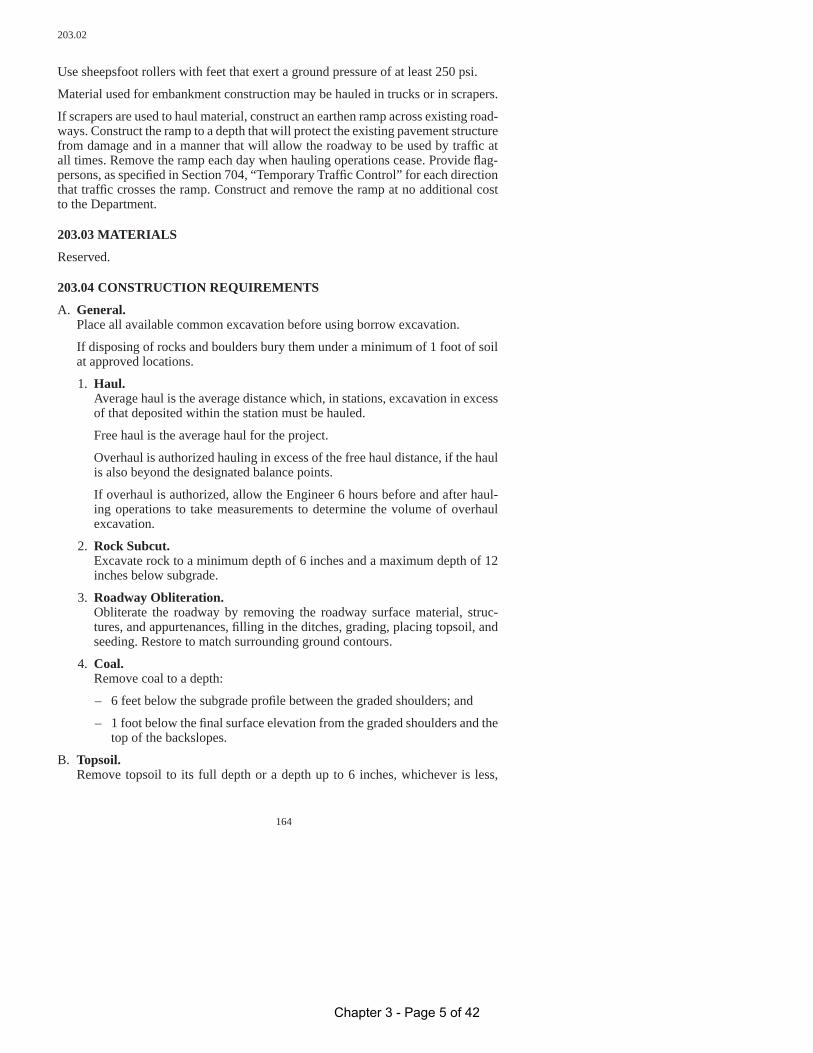
Use sheepsfoot rollers with feet that exert a ground pressure of at least 250 psi.
Material used for embankment construction may be hauled in trucks or in scrapers.
If scrapers are used to haul material, construct an earthen ramp across existing road-ways. Construct the ramp to a depth that will protect the existing pavement structure from damage and in a manner that will allow the roadway to be used by traf c at all times. Remove the ramp each day when hauling operations cease. Provide ag-persons, as speci ed in Section 704, “Temporary Traf c Control” for each direction that traf c crosses the ramp. Construct and remove the ramp at no additional cost to the Department.
203.03 MATERIALS
Reserved.
203.04 CONSTRUCTION REQUIREMENTS
A. General. Place all available common excavation before using borrow excavation.
If disposing of rocks and boulders bury them under a minimum of 1 foot of soil at approved locations.
1. Haul. Average haul is the average distance which, in stations, excavation in excess of that deposited within the station must be hauled.
Free haul is the average haul for the project.
Overhaul is authorized hauling in excess of the free haul distance, if the haul is also beyond the designated balance points.
If overhaul is authorized, allow the Engineer 6 hours before and after haul-ing operations to take measurements to determine the volume of overhaul excavation.
2. Rock Subcut. Excavate rock to a minimum depth of 6 inches and a maximum depth of 12 inches below subgrade.
3. Roadway Obliteration. Obliterate the roadway by removing the roadway surface material, struc-tures, and appurtenances, lling in the ditches, grading, placing topsoil, and seeding. Restore to match surrounding ground contours.
4. Coal. Remove coal to a depth:
– 6 feet below the subgrade pro le between the graded shoulders; and
– 1 foot below the nal surface elevation from the graded shoulders and the top of the backslopes.
B. Topsoil. Remove topsoil to its full depth or a depth up to 6 inches, whichever is less,
Chapter 3 - Page 5 of 42
165
203.04 D.1
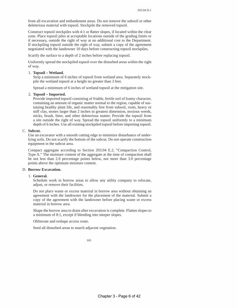
from all excavation and embankment areas. Do not remove the subsoil or other deleterious material with topsoil. Stockpile the removed topsoil.
Construct topsoil stockpiles with 4:1 or atter slopes, if located within the clear zone. Place topsoil piles at acceptable locations outside of the grading limits or if necessary, outside the right of way at no additional cost to the Department. If stockpiling topsoil outside the right of way, submit a copy of the agreement negotiated with the landowner 10 days before constructing topsoil stockpiles.
Scarify the surface to a depth of 2 inches before replacing topsoil.
Uniformly spread the stockpiled topsoil over the disturbed areas within the right of way.
1. Topsoil – Wetland. Strip a minimum of 6 inches of topsoil from wetland area. Separately stock-pile the wetland topsoil at a height no greater than 3 feet.
Spread a minimum of 6 inches of wetland topsoil at the mitigation site.
2. Topsoil – Imported. Provide imported topsoil consisting of friable, fertile soil of loamy character, containing an amount of organic matter normal to the region, capable of sus-taining healthy plant life, and reasonably free from subsoil, roots, heavy or stiff clay, stones larger than 2 inches in greatest dimension, noxious weeds, sticks, brush, litter, and other deleterious matter. Provide the topsoil from a site outside the right of way. Spread the topsoil uniformly to a minimum depth of 6 inches. Use all existing stockpiled topsoil before importing topsoil.
C. Subcut. Use an excavator with a smooth cutting edge to minimize disturbance of under-lying soils. Do not scarify the bottom of the subcut. Do not operate construction equipment in the subcut area.
Compact aggregate according to Section 203.04 E.2, “Compaction Control, Type A.” The moisture content of the aggregate at the time of compaction shall be not less than 2.0 percentage points below, nor more than 3.0 percentage points above the optimum moisture content.
D. Borrow Excavation.
1. General. Schedule work in borrow areas to allow any utility company to relocate, adjust, or remove their facilities.
Do not place waste or excess material in borrow area without obtaining an agreement with the landowner for the placement of the material. Submit a copy of the agreement with the landowner before placing waste or excess material in borrow area.
Shape the borrow area to drain after excavation is complete. Flatten slopes to a minimum of 8:1, except if blending into steeper slopes.
Obliterate and reshape access route.
Seed all disturbed areas to match adjacent vegetation.
Chapter 3 - Page 6 of 42

166
203.04 D.1
Replace fence to its original condition. Ensure livestock is con ned when fencing is removed or altered.
Obtain a borrow source if no Department optioned borrow is provided. The Engineer will allow Contractor furnished borrow unless the Department op-tioned borrow area is mandatory.
Compact borrow as speci ed in Section 203.04 E.2, “Compaction Control, Type A.”
2. Department Optioned Borrow. Identify the legal owners of the borrow area at the time the material is being removed. Use county records for the identi cation of land owners. Include the names of any other parties having a legal interest in the property. Provide this information to the Engineer.
Notify the landowner in writing if exercising the Department’s option, in-cluding the removal plan and location of the access route.
Submit a copy of the written noti cation and any other agreements negoti-ated with the landowner 10 days before starting operations in borrow area.
The Department will be responsible for utility relocations and costs of relo-cations.
Remove, stockpile, and spread topsoil as speci ed in Section 203.04 B, “Topsoil.” Use seed as speci ed in the Contract, if no seed is speci ed use Class II seed mixture as speci ed in Section 251.03, “Materials.”
Submit a copy of the landowner’s release and receipt of payment, after the borrow area has been restored to a satisfactory condition.
If the work is performed in more than 1 calendar year, pay the landowner for the material removed the rst calendar year by December 31 of that year. If a payment arrangement different from the Department’s option is negotiated with the landowner, submit a copy of the agreement.
If a material shortage or other problems occur in the Department optioned area and the Engineer directs that borrow be furnished from an alternate site, the Department will pay for:
– Topsoil and seeding on the basis shown for the Department optioned area;
– Costs in excess of what would be incurred in the Department optioned area; and
– Haul will be measured as speci ed in Section 203.05 H, “Haul.”
3. Contractor Furnished Borrow. The Engineer will determine if the material is suitable for the speci ed use.
Before work begins in the pit, furnish the names of the legal owners and the names of other parties having a legal interest in the borrow areas.
Submit a copy of the borrow agreement.
After the borrow area has been restored to satisfactory condition, obtain a
Chapter 3 - Page 7 of 42

167
203.04 E.2
release and receipt of payment from the legal owners and furnish copies to the Engineer.
Utility adjustments shall be the Contractors responsibility.
E. Embankment Construction.
1. General.Do not place rocks, broken concrete, or other solid materials in embankment areas where piling is to be driven. Do not place any rocks larger than 4 inches in its longest dimension in the top 1 foot of the nished grade.
Do not use frozen material in embankment construction. Do not place mate-rial on frozen ground.
Use motor graders to spread material to a uniform thickness before compact-ing. Continuously level and manipulate the material to obtain uniform soil distribution. Operate construction equipment uniformly over the entire sur-face of each lift. Compact each lift to speci ed density and obtain the proper moisture content before placing the next lift.
Compact private drives, minor road approaches, and other parts of the em-bankment outside the roadbed as speci ed in Section 203.04 E.4, “Compac-tion Control, Type C.”
Bench existing embankment if placing new material against slopes 4:1 or steeper. Do not bench with steps less than 24 inches in width. Begin each horizontal cut at the intersection of the original ground and the vertical sides of the previous cuts. Recompact excavated material along with new embank-ment material.
If the excavated material consists predominantly of rock too large to be placed in 12 inch lifts, place the material uniformly in thicknesses up to the average rock size, but no thicker than 2 feet. Do not use rock ll in the top 2 feet of the nished subgrade.
If placing rock ll over a structure, cover the structure with a minimum of 2 feet of compacted earth or other approved material before placing rock ll.
If placing and compacting material at structures, place and compact the ma-terial in lifts not to exceed 12 inches of loose material. During placement and compaction, ensure that each side is brought up within 12 inches of the other at all times.
Compact without placing excessive pressure against the structure when plac-ing embankment is required only on one side of a structure.
Ensure the ll adjacent to a bridge abutment is no higher than the berm el-evation in front of the abutment until the superstructure is in place.
2. Compaction Control, Type A.Construct all lls, excluding rock lls, with moisture and density controls. Place embankment in lifts not to exceed 12 inches of loose material.
Manipulate substandard areas by working the soil until the speci ed density and uniform moisture content are achieved.
Chapter 3 - Page 8 of 42

168
203.04 E.2
Compact material as speci ed in Section 203.04 E.2.a, “ND T 180” unless the contract speci es otherwise.
a. ND T 180.Compact material to at least 90 percent of the maximum dry density with a moisture content no less than the optimum moisture and no more than 5.0 percentage points above the optimum moisture. The Engineer will determine the maximum dry density and optimum moisture content as speci ed in ND T 180.
b. ND T 99.Compact material to at least 95 percent of the maximum dry density with moisture content no less than 4.0 percentage points below the optimum moisture, and no more than 5.0 percentage points above the optimum moisture. The Engineer will determine the maximum dry density and op-timum moisture content as speci ed in ND T 99.
3. Compaction Control, Type B.Construct embankment in lifts not to exceed 12 inches of loose material, except for rock lls and the rst layer of lls over swampy ground.
Uniformly compact each lift by operating grading equipment and rollers over the entire area. Use a sheepsfoot roller until the roller pads penetrate the surface a maximum of 0.5 inch.
Use separate dumping and compacting areas.
4. Compaction Control, Type C.Construct embankment in lifts not to exceed 8 inches of loose material over the full width of the proposed embankment section, except for rock lls and the rst layer of lls over swampy ground.
Uniformly compact each lift by operating grading equipment over the entire area.
F. Approach Foreslope Reconstruction and Flatten Ditch Block Slopes. Perform topsoil work for excavation and embankment areas as speci ed in Sec-tion 203.04 B, “Topsoil.”
Compact embankment material as speci ed in Section 203.04 E.3, “Compac-tion Control, Type B.”
Place Class II seed mixture as speci ed in Section 251.02, “Equipment;” 251.03, “Materials;” and 251.04, “Construction Requirements.”
Place mulch as speci ed in Section 253.02, “Equipment;” 253.03, “Materials;” and 253.04, “Construction Requirements.”
G. Guardrail Embankment. Compact embankment material as speci ed in Section 203.04 E.2, “Compac-tion Control, Type A.”
Perform topsoil work as speci ed in Section 203.04 B, “Topsoil.”
Seed with Class II seed mixture as speci ed in Section 251.02, “Equipment”; 251.03, “Materials”; and 251.04, “Construction Requirements.”
Chapter 3 - Page 9 of 42

375
SECTION 709 GEOSYNTHETICS
709.01 DESCRIPTION
This work consists of furnishing and installing geosynthetics.
709.02 EQUIPMENT
Reserved.
709.03 MATERIALS
Item SectionGeosynthetics 858
709.04 CONSTRUCTION REQUIREMENTS
A. General. Package, label, identify, handle, and store geosynthetic according to ASTM D 4873. Wrap each geosynthetic roll with a material that will protect the roll, in-cluding the ends of the rolls, from damage due to shipment, water, sunlight, and contaminants. Maintain protective wrapping during periods of shipment and storage. Store geosynthetic onsite elevated off the ground.
Deliver the geosynthetic to the project and submit a certi cate of compliance at least 21 days before its incorporation into the work.
Overlap or sew the joints. Overlap as required for the speci c geosynthetic type. If sewing joints use Kevlar, polypropylene, or polyester thread. Use a 401 stitch conforming to Federal Standard No. 751a for all seams. Use SSn-2 overlapping “J” seams for eld seams. Sew all seams with two parallel stitch lines spaced approximately 1/4 inch apart. Place the outside stitch 1 inch from the edge of the geosynthetic. Sew seams that meet the strength requirements for the speci c geosynthetic type. Furnish a sewn seam sample that has the same geosynthetic material, thread, seam spacing and number, and eld seam overlap distance that will be used in the work.
Type D3 geosynthetics may be constructed using welded seams.
Install geosynthetic only after receiving approval from the Engineer. Place the geosynthetic on a surface that is smooth and free of stones, sticks, and other debris or irregularities that could damage the geosynthetic. Manually pull the geosynthetic taut to remove wrinkles. Do not operate construction equipment directly on the geosynthetic. If sewn, place geosynthetic with all seams up.
After laydown, cover geosynthetic material within 5 days. Remove and replace material that is not covered within 5 days.
B. Geosynthetic Drainage Material (Type D). Secure geosynthetic using the manufacturer’s recommended methods. After se-curing geosynthetic material in place, deposit the aggregate using methods that will not tear, puncture, or reposition the geosynthetic. Do not drop aggregate on
709.04 B
Chapter 3 - Page 10 of 42
376
the geosynthetic from a height greater than 3 feet.
C. Geosynthetic Geogrid (Type G). Unroll geogrid parallel to the centerline of the road. Do not drag the geogrid across the underlying material. Use geogrid widths that produce overlaps of parallel rolls at the centerline and at the shoulders and so that no overlaps are required along wheel paths.
Overlap the geogrid a minimum of 30 inches at all splices or joints. Construct joints at the end of a roll so the previous roll laps over the subsequent roll in the direction of the cover material placement. Mechanically tie transverse joints at 3-foot intervals, and longitudinal joints at 15-foot intervals. Place pins or staples at all corners and at 15-foot intervals along all edges, before placing cover mate-rial on the geogrid.
Stagger end overlaps at least 10 feet from other end overlaps in parallel rolls. On curves, the geogrid may be cut to conform to the curves.
Patch damaged areas of geogrid. Place a patch that overlaps the damaged area by 36 inches on all sides. Align the apertures of the patch and the underlying grid. Mechanically tie the patch to the underlying grid.
Place the rst lift of material over geogrid installed on subgrade to a depth of 10 inches of loose material. Place the rst lift of material over geogrid installed on aggregate base to a depth of 6 inches of loose material.
Use low ground pressure equipment to spread the initial lift of material. If rut-ting occurs, ll the ruts with additional material before placing the subsequent lift. Do not blade out ruts. Do not turn construction equipment on the rst layer of material.
D. Geosynthetic Reinforcement (Type R). Unroll geosynthetic parallel to the centerline of the road. Place the geosynthetic taut and pin the geosynthetic using pins at least 6 inches in length. Place pins at all corners and at 15-foot intervals along all edges, before placing material on the geosynthetic.
Overlap the geosynthetic a minimum of 30 inches at all splices or joints. Con-struct joints at the end of a roll so that the previous roll laps over the subsequent roll in the direction of the material placement.
Patch damaged areas by overlapping the tear a minimum of 36 inches with geo-synthetic and secure the perimeter of the patch area with pins or staples.
Place a 6-inch loose initial lift of material above the geosynthetic. Use low ground pressure equipment to spread the initial lift of material. If rutting occurs, ll the ruts with additional material before placing the subsequent lift. Do not
blade out ruts. Do not turn construction equipment on the rst layer of material.
E. Geosynthetic for Riprap (Type RR). Place geosynthetic with the longest dimension parallel to the direction of wa-ter ow. Place overlaps so the upstream strip overlaps the downstream strip. Overlap splices and joints at least 18 inches. Overlap splices and joints placed underwater at least 36 inches. Pin or staple all overlaps at 3-foot intervals.
709.04 B
Chapter 3 - Page 11 of 42

377
Patch damaged areas by overlapping the tear a minimum of 36 inches with geo-synthetic and secure the perimeter of the patch area with pins or staples.
Material placed to protect against wave action may be unrolled parallel or per-pendicular to the water’s edge. Sew all joints that are parallel to the water’s edge.
F. Geosynthetic Separation Material (Type S). Unroll the geosynthetic in line with the placement of the new material. Do not drag the geosynthetic across the underlying material. Use geosynthetic widths that produce overlaps of parallel rolls at the centerline and at the shoulders and so that no overlaps are required along wheel paths.
Overlap the geosynthetic a minimum of 18 inches at all splices or joints. Con-struct joints at the end of a roll so that the previous roll laps over the subsequent roll in the direction of the material placement.
Patch damaged areas by overlapping the tear a minimum of 36 inches with geo-synthetic and secure the perimeter of the patch area with pins or staples.
Secure the geosynthetic using the manufacturer’s recommended methods.
Place the initial lift of material above the geosynthetic to a depth of 9 inches of loose material. When placing the initial lift of material, limit construction equip-ment in size and weight so rutting in the initial lift is less than 3 inches. If rutting occurs, ll the ruts with additional material before placing the subsequent lift. Do not blade out ruts. Do not turn construction equipment on the rst layer of material.
709.05 METHOD OF MEASUREMENT
The Engineer will measure, completed and in place, as speci ed in Section 109.01, “Measurement of Quantities” and as follows:
The Engineer will not measure overlaps, drainage trenches, or cutoffs.
709.06 BASIS OF PAYMENT
Pay Item Pay Unit Geosynthetic Material Type __ Square Yard
Such payment is full compensation for furnishing all materials, equipment, labor, and incidentals to complete the work as speci ed.
709.06
Chapter 3 - Page 12 of 42

378
SECTION 714 CULVERTS, STORM DRAINS, EDGEDRAINS,
AND UNDERDRAINS
714.01 DESCRIPTION
This work consists of installing culverts, storm drains, edgedrains, and underdrains.
714.02 EQUIPMENT
Reserved.
714.03 MATERIALS
A. Culverts and Storm Drains.
Item SectionConcrete Culvert and Storm Drain Pipe 830.01 A
Reinforced Concrete Culvert and Storm Drain Pipe 830.01 B Metallic (Zinc or Aluminum Coated Corrugated Steel Culverts, Storm Drains, and Underdrains 830.02 B Smooth Wall Steel Pipe Culverts 830.02 F Polymer Coated Corrugated Steel Pipe 830.02 C Corrugated Polyethylene Culverts 830.03 F Geosynthetic Material – Type S2 858.01
Provide mortar consisting of a mixture of one part Portland Cement to two parts mortar sand, and suf cient water to furnish proper consistency.Where placing new end sections on existing pipe, identify whether the type of end section need-ed is male or female.
B. Underdrains.
Item SectionPerforated, Corrugated Polyethylene 830.03 A.4
Table 714-01Underdrain Aggregate GradationSieve Size Percent Passing3/8 Inch 100
No. 4 95 – 100No. 16 45 – 80No. 50 10 – 30No. 100 0 – 10No. 200 0 – 3
714.03 B
Chapter 3 - Page 13 of 42
379
C. Bridge Approach Drains.
Item SectionPlastic Pipe (perforated and non-perforated) 830.03 A.4
Geosynthetic Material – Type D1 858
Table 714-02Bridge Approach Drain GradationSieve Size Percent Passing
1 inch 1003/4 inch 90 – 1003/8 inch 20 – 55
No. 4 0 – 10No. 8 0 – 5
No. 200 0 – 1.0
D. Edgedrains.
Item SectionClass 43 Aggregate 816.03
Perforated, Corrugated, P.E. Pipe 830.03 A.4 PVC Discharge Pipe 830.03 A.3 Geosynthetics 858
The shale and L.A. abrasion requirements will not be required for Class 43 Ag-gregate.
E. Structural Plate Pipe. Material shall meet Section 830.02, “Metal Pipe.”
714.04 CONSTRUCTION REQUIREMENTS
If the existing drainage facilities become inoperable before the new drainage sys-tem is functioning, provide suf cient temporary pumping and drainage facilities to keep the roadway drained. Include the cost of providing suf cient temporary pump-ing and drainage in the price bid for other items.
Dispose of unsuitable or excess excavation at an approved location.
A. General.
1. Bedding. Construct bedding for approach pipes to meet the conduit manufacturer’s recommendations.
Tamp bedding material in place under both haunches of the pipe up 15 per-cent of the total height by hand-held air-operated, mechanical tampers
2. Laying Pipe. Begin laying pipe at the downstream end. Place the pipe in contact with the shaped bedding throughout its full length. Place bell or groove ends of rigid pipe and outside circumferential laps of exible pipe facing upstream.
714.04 A.2
Chapter 3 - Page 14 of 42

380
3. Joining Pipe.Provide rigid pipe with bell and spigot or tongue and groove joints. Join pipesections so the ends are fully entered and the inner surfaces are ush andeven. Wrap joints on concrete pipes in Type S2 geotextile fabric.
Install pipe ties on all joints on concrete pipes, including the end sectionjoint.
4. Relaid Pipe.Clean all salvaged pipe of foreign material before reinstallation.
Furnish connecting devices or seals needed to join pipe or end sections.
5. Defl ection Testing.Test all metal and thermoplastic pipe used for mainline and paved intersect-ing roadways for de ection a minimum of 30 days after the pipe is installed.Pass a 9-point mandrel or other approved object through the pipe to checkfor de ection. Use a mandrel with a diameter not less than 95 percent of theinside diameter of the pipe. If the mandrel cannot be passed through the pipe,replace the pipe.
The Engineer will visually inspect thermoplastic pipe under unpaved ap-proaches for de ection. If the Engineer sees any de ection, the Engineer willrequire the Contractor to pass a 9-point mandrel or other approved objectthrough the pipe to check for de ection. Use a mandrel with a diameter notless than 95 percent of the inside diameter of the pipe. If the mandrel cannotbe passed through the pipe, replace the pipe.
Perform the de ection test under the observation of the Engineer.
6. Connection to Manholes, Inlets, and Pipes.If connections required to a manhole, inlet barrel, or pipe entrance, connectpipe by cutting the opening and grouting in the connecting pipe.
7. Compaction Control for Aggregate.Compact aggregate according to Section 203.04 E.2, “Compaction Control,Type A” The moisture content of the aggregate at the time of compactionshall be not less than 2.0 percentage points below, nor more than 3.0 percent-age points above the optimum moisture content.
8. Compaction Control for Non-Aggregate Material.If Common Excavation Type A is speci ed, follow the compaction require-ments in Section 203.04 E.2, “Compaction Control, Type A.” If CommonExcavation Type B is speci ed, follow the compaction requirements in Sec-tion 203.04 E.3, “Compaction Control, Type B.”
Use a maximum lift thickness of 6 inches.
9. Construction Cover.Meet the pipe manufacturer’s recommendation cover requirements duringconstruction operations.
Repair or remove and replace any pipe damaged by construction traf c.
714.04 A.3
See Supplemental Spec 10/01/15
Chapter 3 - Page 15 of 42

Chapter 3 - Page 16 of 42
CERTIFICATION
I hereby certify the attached supplemental specifications effective on October 1, 2015. /S/ 6/1/15 Bob Fode, P.E., Director Office of Project Development
Date
Chapter 3 - Page 17 of 42
Page 17 of 30
Use low ground pressure equipment to spread the initial lift of material. If rutting occurs, fill the ruts with additional material before placing the subsequent lift. Do not blade out ruts. Do not turn construction equipment on the first layer of material.
714.04 A.1 Bedding PAGE 379 10/01/15 Delete the first paragraph from Section 714.04 A.1. 714.04 A.6 Connection to Manholes, Inlets, and Pipes PAGE 380 10/01/15 Replace Section 714.04 A.6 with the following: 6. Connection to Manholes, Inlets, and Pipes.
If connections are required to a manhole, inlet barrel, or pipe entrance, connect pipe by cutting the opening and grouting in the connecting pipe.
714.04 A.7 Compaction Control for Aggregate PAGE 380 10/01/15 Replace Section 714.04 A.7 with the following:
7. Compaction Control for Aggregate.
Compact aggregate according to Section 203.04 E.2, “Compaction Control, Type A” The moisture content of the aggregate at the time of compaction shall be not less than 2.0 percentage points below, nor more than 3.0 percentage points above the optimum moisture content. Compact aggregate for approach pipes according to the conduit manufacturer’s recommendation Use a maximum lift thickness of 6 inches.
714.04 A.8 Compaction Control for Non-Aggregate Material PAGE 380 10/01/15 Replace Section 714.04 A.8 with the following: 8. Compaction Control for Non-Aggregate Material.
If Common Excavation Type A is specified, follow the compaction requirements in Section 203.04 E.2, “Compaction Control, Type A”. If Common Excavation Type B is specified, follow the compaction requirements in Section 203.04 E.3, “Compaction Control, Type B”. Compact material for approach pipes according to the conduit manufacturer’s recommendations.
748.03 MATERIALS PAGE 393 10/01/15 Add the following item to the table:
Impervious Membrane Cure 810.01 B.1 or 810.01 B.2
Chapter 3 - Page 18 of 42
FIELD SAMPLING AND TESTING MANUAL
SECTION 200
EARTHWORK
Chapter 3 - Page 19 of 42
SECTION 200 TABLE OF CONTENTS
Section 203 Excavation and Embankment 203.01 Description 203.02 Excavation 203.03 Embankment – Acceptance Samples and Tests 203.04 Independent Assurance (IA) Samples and Tests Section 210 Structural and Channel Excavation, Foundation Fill and Preparation 210.01 Description 210.02 Excavation 210.03 Acceptance Samples and Tests 210.04 Independent Assurance (IA) Samples and Tests Section 230 Reshaping Roadway and Subgrade Preparation 230 Description 230.1 Acceptance Samples and Tests 230.2 Independent Assurance Samples and Tests Section 234 Stabilized Subgrade 234 Description 234.1 Acceptance Samples and Tests 234.2 Independent Assurance Samples and Tests Reference Forms: DOT 13942 Conversion Chart for Speedy Tester SFN 2454 Density Test Worksheet – Volume Measure SFN 9987 Aggregate Sample Worksheet SFN 10063 Moisture-Density Relationship Tests SFN 13889 Project Records Samples/Tests Report SFN 59724 Sand Cone Correction Factor SFN 59725 Density Test Worksheet – Sand Cone Method All test procedures used within and referred to in this section can be found under “Testing Procedures” of this manual. Only use the current forms off of the NDDOT website under “Forms” instead of the blank copies found at the end of each section. The copies placed in this manual are for reference only and are not updated regularly.
Chapter 3 - Page 20 of 42

Section 203 Excavation and Embankment
203.01 Description.
This work consists of the excavation, haul, placement, disposal, and compaction of embankment material.
203.02 Excavation. No testing required. 203.03 Embankment – Acceptance Samples and Tests.
A. Engineer Responsibility.
The Engineer will collect material and conduct testing to verify the material meets the requirements of ‘Compaction Control’ in Section 203.04.E.2 of the NDDOT Standard Specifications for Road and Bridge Construction.
1. Compaction Control, Type A.
Table 203-1 shows test method and frequency for embankment compaction control.
Table 203-1
Test Frequency ND T 180 or ND T 99, “Moisture-Density Relations of Soils (Multi-Point)”
1 compaction curve for each change in soil.
ND D 2167, “Density and Unit Weight of Soil in Place by the Rubber Balloon Method,” or ND T 191, “Density of Soil In-Place by the Sand Cone Method”
1 test per 1,500 feet of compacted roadway per 12” lift.
ND T 265, “Laboratory Determination of Moisture Content of Soils;” or ND T 217, “Determination of Moisture in Soil by Means of Calcium Carbide Gas Pressure Tester (Speedy);” or ND D 4643, “Microwave Method of Drying Soils”
1 test per 1,500 feet of compacted roadway per 12” lift.
Sample locations will be randomly selected by the Engineer.
Chapter 3 - Page 21 of 42
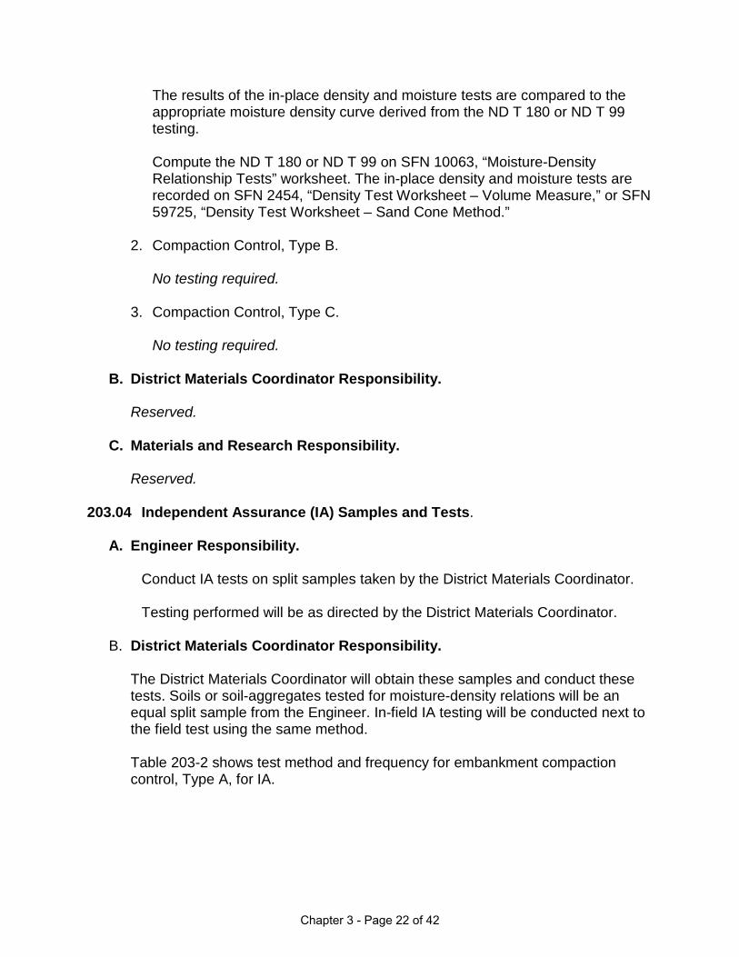
The results of the in-place density and moisture tests are compared to the appropriate moisture density curve derived from the ND T 180 or ND T 99 testing. Compute the ND T 180 or ND T 99 on SFN 10063, “Moisture-Density Relationship Tests” worksheet. The in-place density and moisture tests are recorded on SFN 2454, “Density Test Worksheet – Volume Measure,” or SFN 59725, “Density Test Worksheet – Sand Cone Method.”
2. Compaction Control, Type B.
No testing required.
3. Compaction Control, Type C.
No testing required.
B. District Materials Coordinator Responsibility. Reserved.
C. Materials and Research Responsibility.
Reserved.
203.04 Independent Assurance (IA) Samples and Tests.
A. Engineer Responsibility. Conduct IA tests on split samples taken by the District Materials Coordinator. Testing performed will be as directed by the District Materials Coordinator.
B. District Materials Coordinator Responsibility.
The District Materials Coordinator will obtain these samples and conduct these tests. Soils or soil-aggregates tested for moisture-density relations will be an equal split sample from the Engineer. In-field IA testing will be conducted next to the field test using the same method. Table 203-2 shows test method and frequency for embankment compaction control, Type A, for IA.
Chapter 3 - Page 22 of 42

Table 203-2 Test Frequency ND T 180 or ND T 99, “Moisture-Density Relations of Soils (Multi-Point)”
1 compaction curve for each three miles of roadway, or a minimum of 1 test per 200,000 C.Y.
ND D 2167, “Density and Unit Weight of Soil in Place by the Rubber Balloon Method,” or ND T 191, “Density of Soil In-Place by the Sand Cone Method”
1 density test for each three miles of roadway, or a minimum of 1 test per 200,000 C.Y.
ND T 265, “Laboratory Determination of Moisture Content of Soils,” or ND T 217, “Determination of Moisture in Soil by Means of Calcium Carbide Gas Pressure Tester (Speedy),” or ND D 4643, “Microwave Method of Drying Soils”
1 moisture test for each three miles of roadway, or a minimum of 1 test per 200,000 C.Y.
Compute the ND T 180 or ND T 99 on SFN 10063, “Moisture-Density Relationship Tests” worksheet. The in-place density and moisture tests are recorded on SFN 2454, “Density Test Worksheet – Volume Measure,” or SFN 59725, “Density Test Worksheet – Sand Cone Method.”
Engineer and District Materials Coordinator will compare the test results for IA tolerance in Table 203-3.
Table 203-3
Test Tolerance ND T 180 or ND T 99, “Moisture-Density Relations of Soils (Multi-Point)”
± 4 lbs. cu. ft. (MDD) ± 1.5 (OM)
ND D 2167, “Density and Unit Weight of Soil in Place by the Rubber Balloon Method,” or ND T 191, “Density of Soil In-Place by the Sand Cone Method”
± 5 lbs. cu. ft.
ND T 265, “Laboratory Determination of Moisture Content of Soils,” or ND T 217, “Determination of Moisture in Soil by Means of Calcium Carbide Gas Pressure Tester (Speedy),” or ND D 4643, “Microwave Method of Drying Soils”
± 2.0
Chapter 3 - Page 23 of 42

If the initial IA testing is not within specified tolerances, the Engineer shall obtain an additional sample for testing under the observation of the District Materials Coordinator.
The Engineer and District Materials Coordinator shall conduct equipment checks and review testing procedures. This will continue until the differences are resolved.
C. Materials and Research Responsibility.
Reserved.
Chapter 3 - Page 24 of 42

Section 210 Structural and Channel Excavation, Foundation Fill and Preparation
210.01 Description.
This work consists of excavation as defined in the plans. 210.02 Excavation. No testing required. 210.03 Acceptance Samples and Tests.
A. Engineer Responsibility.
The Engineer will collect material and conduct testing to verify material meets the requirements of Section 210.03.B and 714.04.A.7, 8 of the NDDOT Standard Specifications for Road and Bridge Construction. Table 210-1 shows test methods and frequency for compaction control.
Table 210-1
Tests Frequency ND T 180 or ND T 99, “Moisture-Density Relations of Soils (Multi-Point)”
1 compaction curve for each change in material.
ND D 2167, “Density and Unit Weight of Soil in Place by the Rubber Balloon Method,” or ND T 191, “Density of Soil In-Place by the Sand Cone Method”
1 test per 1 foot in elevation.
ND T 265, “Laboratory Determination of Moisture Content of Soils,” or ND T 217, “Determination of Moisture in Soil by Mean of Calcium Carbide Gas Pressure Tester (Speedy),” or ND D 4643, “Microwave Method of Drying Soils”
1 test per 1 foot in elevation.
Sample locations will be randomly selected by the Engineer.
The results of the in-place density and moisture tests are compared to the appropriate moisture density curve derived from the ND T 180 or ND T 99 testing.
Compute the ND T 180 or ND T 99 on SFN 10063, “Moisture-Density Relationship Tests” worksheet. The in-place density and moisture tests are
Chapter 3 - Page 25 of 42

recorded on SFN 2454, “Density Test Worksheet – Volume Measure,” or SFN 59725, “Density Test Worksheet – Sand Cone Method.” Table 210-2 shows test method and frequency for aggregate placed.
Table 210-2
Test Frequency ND T 27, “Sieve Analysis of Fine and Coarse Aggregates”
1 test result per 2,500 C.Y.
ND T 11, “Materials Finer Than No. 200 Sieve in Mineral Aggregates by Washing”
1 test result per 2,500 C.Y.
NDDOT 4, “Percentage of Fracture Particles in Coarse Aggregate”
1 test result per 2,500 C.Y.
ND T 113, “Lightweight Pieces in Aggregate” 1 test result per 2,500 C.Y.
Compute the sieve analysis results on SFN 9987, “Aggregate Sample Worksheet.” Results are recorded on SFN 10072, “Aggregate Quality Test Summary.”
B. District Materials Coordinator Responsibility.
Reserved.
C. Materials and Research Responsibility.
Reserved.
210.04 Independent Assurance (IA) Samples and Tests.
A. Engineer Responsibility.
Conduct IA tests on split samples taken by the District Materials Coordinator. Testing performed will be as directed by the District Materials Coordinator.
B. District Materials Coordinator Responsibility. The District Materials Coordinator will obtain these samples and conduct these tests. These samples will be an equal split sample from the Engineer.
Chapter 3 - Page 26 of 42

Samples will be obtained and split according to ND T 2, “Sampling of Aggregates,” and ND T 248, “Reducing Samples of Aggregate to Testing Size.” Soils or soil-aggregates tested for moisture-density relations will be an equal split sample from the Engineer. In-field IA testing will be conducted next to the field test, using the same method. Table 210-3 shows test method and frequency for IA.
Table 210-3
Test Frequency ND T 180 or ND T 99, “Moisture-Density Relations of Soils (Multi-Point)”
1 compaction curve for each three miles of roadway, or a minimum of 1 test per 200,000 C.Y.
ND D 2167, “Density and Unit Weight of Soil in Place by the Rubber Balloon Method,” or ND T 191, “Density of Soil In-Place by the Sand Cone Method”
1 density test for each three miles of roadway, or a minimum of 1 test per 200,000 C.Y.
ND T 265, “Laboratory Determination of Moisture Content of Soils,” or ND T 217, “Determination of Moisture in Soil by Mean of Calcium Carbide Gas Pressure Tester (Speedy),” or ND D 4643, “Microwave Method of Drying Soils”
1 moisture test for each three miles of roadway, or a minimum of 1 test per 200,000 C.Y.
ND T 27, “Sieve Analysis of Fine and Coarse Aggregates”
Minimum 1 test result per project.
ND T 11, “Materials Finer Than No. 200 Sieve in Mineral Aggregates by Washing”
Minimum 1 test result per project.
NDDOT 4, “Percentage of Fracture Particles in Coarse Aggregate”
Minimum 1 test result per project.
ND T 113, “Lightweight Pieces in Aggregate” Minimum 1 test result per project.
Compute the ND T 180 or ND T 99 on SFN 10063, “Moisture-Density Relationship Tests” worksheet. The in-place density and moisture tests are recorded on SFN 2454, “Density Test Worksheet – Volume Measure,” or SFN 59725, “Density Test Worksheet – Sand Cone Method.” The Engineer and District Materials Coordinator will compare the test results for IA tolerance in Table 210-4.
Chapter 3 - Page 27 of 42

Table 210-4
Test Tolerance ND T 180 or ND T 99, “Moisture-Density Relations of Soils (Multi-Point)”
± 4 lbs. cu. ft. (MDD) ± 1.5 (OM)
ND D 2167, “Density and Unit Weight of Soil in Place by the Rubber Balloon Method,” or ND T 191, “Density of Soil In-Place by the Sand Cone Method”
± 5 lbs. cu. ft.
ND T 265, “Laboratory Determination of Moisture Content of Soils,” or ND T 217, “Determination of Moisture in Soil by Mean of Calcium Carbide Gas Pressure Tester (Speedy),” or ND D 4643, “Microwave Method of Drying Soils”
± 2.0
ND T 27, “Sieve Analysis of Fine and Coarse Aggregates,” and ND T 11, “Materials Finer than No. 200 Sieve in Mineral Aggregates by Washing”: No. 4 sieve and larger No. 30 sieve No. 200 sieve
±5 ±3 ±2
NDDOT 4, “Percentage of Fracture Particles in Coarse Aggregate”
±5
ND T 113, “Lightweight Pieces in Aggregate” ±2
If the initial IA testing is not within specified tolerances, the Engineer shall obtain an additional sample for testing under the observation of the District Materials Coordinator.
The Engineer and District Materials Coordinator shall conduct equipment checks and review testing procedures. This will continue until the differences are resolved.
C. Materials and Research Responsibility.
Reserved.
Chapter 3 - Page 28 of 42
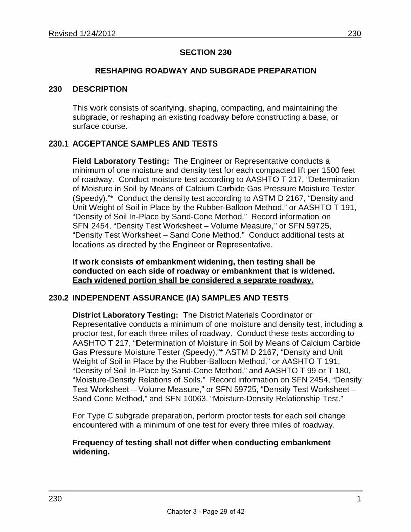
Revised 1/24/2012 230
230 1
SECTION 230
RESHAPING ROADWAY AND SUBGRADE PREPARATION
230 DESCRIPTION
This work consists of scarifying, shaping, compacting, and maintaining the subgrade, or reshaping an existing roadway before constructing a base, or surface course.
230.1 ACCEPTANCE SAMPLES AND TESTS
Field Laboratory Testing: The Engineer or Representative conducts aminimum of one moisture and density test for each compacted lift per 1500 feet of roadway. Conduct moisture test according to AASHTO T 217, “Determination of Moisture in Soil by Means of Calcium Carbide Gas Pressure Moisture Tester (Speedy).”* Conduct the density test according to ASTM D 2167, “Density and Unit Weight of Soil in Place by the Rubber-Balloon Method,” or AASHTO T 191, “Density of Soil In-Place by Sand-Cone Method.” Record information on SFN 2454, “Density Test Worksheet – Volume Measure,” or SFN 59725, “Density Test Worksheet – Sand Cone Method.” Conduct additional tests at locations as directed by the Engineer or Representative.
If work consists of embankment widening, then testing shall be conducted on each side of roadway or embankment that is widened. Each widened portion shall be considered a separate roadway.
230.2 INDEPENDENT ASSURANCE (IA) SAMPLES AND TESTS
District Laboratory Testing: The District Materials Coordinator or Representative conducts a minimum of one moisture and density test, including a proctor test, for each three miles of roadway. Conduct these tests according to AASHTO T 217, “Determination of Moisture in Soil by Means of Calcium Carbide Gas Pressure Moisture Tester (Speedy),”* ASTM D 2167, “Density and Unit Weight of Soil in Place by the Rubber-Balloon Method,” or AASHTO T 191, “Density of Soil In-Place by Sand-Cone Method,” and AASHTO T 99 or T 180, “Moisture-Density Relations of Soils.” Record information on SFN 2454, “Density Test Worksheet – Volume Measure,” or SFN 59725, “Density Test Worksheet – Sand Cone Method,” and SFN 10063, “Moisture-Density Relationship Test.”
For Type C subgrade preparation, perform proctor tests for each soil change encountered with a minimum of one test for every three miles of roadway.
Frequency of testing shall not differ when conducting embankment widening.
Chapter 3 - Page 29 of 42

Revised 1/24/2012 230
230 2
Field applications typically require the use of the “Speedy” to determine soils moisture content, but it may be practical to use AASHTO T 265,“Laboratory Determination of Moisture Content,” or ASTM D 4643, “Microwave Method of Drying Soils,” in its place. However, acceptance testing and Independent Assurance (IA) testing must be completed using the same soils moisture determination method.
Materials and Research Division Testing: No specified number of tests isrequired. The Materials and Research Division will perform moisture-density relationship tests according to AASHTO T 99 or T 180, “Moisture-Density Relations of Soils,” if requested to do so by the District Materials Coordinator.
Chapter 3 - Page 30 of 42

TABLE OF CONTENTS - 700
Section 704 TRAFFIC CONTROL
704.01 DESCRIPTION.704.02 ACCEPTANCE.
Section 708 EROSION CONTROL708.01 DESCRIPTION.708.02 GENERAL.
A. Seeding. B.Mulching.
C. Fabric Formed Slope Protection. D. Concrete Slope Protection.
1. Required Tests and Frequency.a. Acceptance Samples and Testing--Field Laboratory Testing.b. Independent Assurance Samples and Testing.
1. District Laboratory Testing.2. Materials and Research Division Testing.
2. Reinforcing Steel and Welded Wire Fabric.3. Preformed Expansion Joint Material.
Section 709 GEOTEXTILE MATERIALS709 Description709.1 Definitions709.2 Documentation709.3 General Procedures
Section 714 CULVERTS, STORM DRAINS, EDGE DRAINS, AND UNDERDRAINS714 Description714.1 Acceptance Samples and Tests714.2 Acceptance Samples and Tests for Compaction Control for Pipe Backfill714.3 Independent Assurance Samples and Tests Compaction Control for Pipe
Backfill714.4 Independent Assurance (IA) Samples and Tests for Underdrain
Section 720 MONUMENTS AND RIGHT OF WAY MARKERS720.01 DESCRIPTION.720.02 ACCEPTANCE.
Section 722 MANHOLES, CATCH BASINS, AND INLETS722.01 DESCRIPTION.722.02 ACCEPTANCE.
Revised 6/26/2014 1
Chapter 3 - Page 31 of 42

Intentionally Left Blank
Chapter 3 - Page 32 of 42
Revised 6/26/2014 709
SECTION 709
GEOTEXTILE MATERIALS 709 DESCRIPTION
This section relates to field sampling of geotextile material.
709.1 DEFINITIONS
1. Lot: The NDDOT considers a lot to be a shipment of material delivered to the
location of work. If there is documentation showing that the shipment camefrom different production plants or was manufactured using different materials or procedures, the different parts of the shipment will be considered separatelots.
2. Samples: For geotextile, the samples are taken from the shipping units (i.e.,
rolls of fabric) making up a lot. The property variables of the samples must represent the entire lot. These samples will be submitted for acceptance testing.
3. Certificate of Compliance: As outlined and detailed in Section 106.01 of
NDDOT Standard Specifications, it states that the material fully comply with the Contract requirements.
709.2 DOCUMENTATION
The Engineer or designated field personnel shall obtain a valid Certificate ofCompliance from the contractor and verify that it meets the requirements in Section 858 of NDDOT Standard Specifications. If the material properties statedon the Certificate do not meet the specifications, the material is not acceptable.If it is verified that the properties stated on the Certificate comply with Section858, the Engineer shall contact Materials and Research for inquires on historicaltest information. If any of the criteria listed below are met, then the Engineer may elect to proceed with sampling.
• If the material is unknown to the NDDOT, or has a history of test failures,
samples will be required.• If a significant quantity of geotextile material is being used, or the project has
been selected for random testing, samples may be required.• If the Engineer is concerned about the quality of the geotextile, or that the
Certificate does not represent the material on site, sampling and testing may be ordered at the direction of the Engineer.
709 1Chapter 3 - Page 33 of 42

Revised 6/26/2014 709 709.3 GENERAL PROCEDURES
A. Sampling Overview
1. Sampling Frequency: To determine the number of samples to obtain for
acceptance testing, consider the total units (i.e., rolls) of the lot or lotsdelivered to the work location. All geotextiles shall be sampled randomly.Refer to the following table (Table A) for lot sampling frequency.
Table A
Numbers of Rolls in the Lot Number of Samples Selected
1 to 2 13 to 8 2
9 to 27 328 to 64 4
65 to 125 5126 to 216 6217 to 343 7344 to 512 8513 to 729 9730 to 1000 10
1000 or more 11
2. Sample Size: When cutting a sample from a geotextile roll, do not samplethe first 3 feet or the last 3 feet of the roll. Obtain a sample extending thewidth of the roll and approximately 6 feet in length.
B. Sewn Geotextiles
• Samples shall be taken of geotextiles which have been joined by a sewn-
seam. Tests will be completed to verify that the requirements stated in Section 858 of NDDOT Standard Specifications are met.
• Sample size shall be a minimum 6 feet in length and 3 feet on each side of
the sewn-seam.
• Sampling frequency: Take a minimum of one sample per project. Further sampling shall be at the discretion of the Project Engineer.
C. Precut Geotextiles
• Individual rolls may be cut to pre-selected widths prior to delivery to the
project. Each of these cut portions must be labeled in a manner thatallows identification of its original position within the previous full-width roll.
709 2
Chapter 3 - Page 34 of 42
Revised 6/26/2014 709
The contractor shall provide lists identifying the original full-width rolls andthe portions cut from those rolls.
• The contractor is responsible for assuring all portions of the original rolls
are readily accessible and identifiable for sampling. Sampling is conducted by taking the required sample length of each portion as if it were the original roll. The composition of these cut portions areconsidered one sample.
• The total number of original rolls shall be used to determine how many
samples are needed and is determined from Table A.
D. Sample Identification
Field samples submitted to Materials and Research for testing shall includethe following:
1. A valid Certificate of Compliance conforming to Section 106.01 of NDDOT
Standard Specifications.
2. Samples shall have the following information physically attached to each sample.
a) Project number b) Sampled byc) Date sampledd) Manufacturer’s namee) Product name or stylef) Assign a unique number to identify the sample (whether provided or
created). 709 3
Chapter 3 - Page 35 of 42

Revised 3/19/2014 714
714 1
SECTION 714
CULVERTS, STORM DRAINS, EDGE DRAINS, AND UNDERDRAINS
714 DESCRIPTION
This work consists of constructing culverts, storm drains, edge drains, andunderdrains and shall include excavation and backfilling.
714.1 ACCEPTANCE SAMPLES AND TESTS
Metallic (Zinc or Aluminum) Coated Corrugated Steel Culverts, Corrugated Aluminum Alloy Culverts, and Smooth-Wall Steel Pipe Culverts: Accept all of these materials by certification. The certification must show the project number, contractor, kind of material, size, gauge, quantity of material, and must state that the listed materials conform to the requirements outlined in the applicable specifications. Do not install pipe that is not covered by an approved certification. After the material has been delivered to the project, the Engineer will examine it for the following markings and record the information in his diary or the Pipe Book:
1. Location of the installation - Sta., etc.2. Name of sheet manufacturer.3. Brand name and type of base material.4. Galvanized sheet thickness.5. Weight of coating.6. Coating lot numbers.7. AASHTO or ASTM specification number.8. Diameter and lengths.
Also examine each item for damage in transit and general workmanship. Document the reason for rejection. The following defects are specified as constituting poor workmanship and the presence of any or all of them in anyindividual culvert pipe constitute rejection:
1. Uneven laps.2. Elliptical shaping - unless ordered in this shape.3. Variation from straight centerline.4. Ragged or diagonal sheared edges.5. Loose, unevenly lined or spaced rivets or spot welds.6. Poorly formed rivet heads or loose seams.7. Unfinished ends.8. Illegible brands.9. Lack of rigidity.
10. Bruised, sealed, or broken spelter coating.11. Dents, bends, or holes in the metal itself.
Chapter 3 - Page 36 of 42

Revised 3/19/2014 714
714 2
Concrete Pipe: Refer to the section “Quality Assurance Program for Prestressed and Precast Concrete Products” in this manual.
Plastic, PVC, and Polyethylene Pipe: Pipes manufactured from these materials are accepted by certification.
Underdrain Granular Fill Material:
Field Laboratory Testing: The Engineer obtains one sample for every 15,000 lineal feet placed for sieve analysis. Obtain the sample according to AASHTO T 2, “Sampling of Aggregate,” split the sample according to AASHTO T 248, “Reducing Samples of Aggregate to Testing Size,” and run the sieve analysis according to AASHTO T 11, “Materials Finer than No. 200 Sieve in Mineral Aggregate by Washing,” and AASHTO T 27, “Sieve Analysis of Fine and Coarse Aggregates.” Obtain a minimum of two samples per project.
Grates, Frames, and Boxes: These items are accepted by certification.
714.2 ACCEPTANCE SAMPLES AND TESTS FOR COMPACTION CONTROL FORPIPE BACKFILL
The Engineer, or Representative, must obtain one aggregate sample for sieve analysis of select backfill or foundation fill for every source used. The samplesare obtained according to AASHTO T 2, “Sampling of Aggregates,” and tested according to AASHTO T 27, “Sieve Analysis of Fine and Coarse Aggregates.”Compute the sieve analysis results on SFN 9987, “Aggregate SampleWorksheet.”
The Engineer, or Representative, must conduct a minimum of one moisture anddensity test for each layer of compacted aggregate. A layer of compacted aggregate is defined by a thickness of 12 inches and a maximum length of 200 lineal feet. The width shall be defined by the trench width except each side of thepipe shall be considered as separate layers.
The sketch on page 3 of this section illustrates the testing and compaction intervals.
Chapter 3 - Page 37 of 42

Revised 3/19/2014 714
714 3
Conduct tests according to ASTM D 4643, “Determination of Water Content of Soil by Microwave Oven Method”; AASHTO T 255, “Total Evaporable Moisture ofAggregate by Drying”; AASHTO T 191, “Density of Soil In-Place by Sand-Cone Method”; or AASHTO D 2167, “Density and Unit Weight of Soil in Place by the Rubber-Balloon Method.”
Compare the results derived from these tests to the compaction curve developed from a multi-point Proctor test derived from AASHTO T 180, “Moisture-Density Relations of Soils.” Establish a new compaction curve for each type of material encountered.
714.3 INDEPENDENT ASSURANCE SAMPLES AND TESTS COMPACTIONCONTROL FOR PIPE BACKFILL
The District Materials Coordinator, or Representative, must conduct a moisture and density test at a minimum rate of one test for every 1,000 lineal feet or fraction thereof. Independent assurance testing must be completed using the same tests conducted for acceptance. For quantities less than 1,000 lineal feet, no specified number of tests is required. It shall be to the District Materials Coordinators discretion to make this determination.
A minimum of one comparison Proctor test shall be conducted according to AASHTO T 180, "Moisture-Density Relations of Soils," for every source used.For a quantity less than 1,000 lineal feet, no specified number of tests isrequired.
Chapter 3 - Page 38 of 42
Revised 3/19/2014 714
714 4
714.4 INDEPENDENT ASSURANCE (IA) SAMPLES AND TESTS FOR UNDERDRAIN
Granular Fill Material:
District Laboratory Testing: The District Materials Coordinator obtains one sample from each project for sieve analysis. Obtain the sample according to AASHTO T 2, “Sampling of Aggregate,” split the sample according to AASHTO T 248, “Reducing Samples of Aggregate to Testing Size,” and run the sieve analysis according to AASHTO T 11, “Materials Finer than No. 200 Sieve in Mineral Aggregate by Washing,” and AASHTO T 27, “Sieve Analysis of Fine and Coarse Aggregate.”
Chapter 3 - Page 39 of 42

Chapter 3 - Page 40 of 42
MATERIALS AND RESEARCH MEMORANDUM 1-2010 TO: District Materials Coordinators FROM: Ron Horner
Materials & Research Engineer DATE: May 20, 2010 SUBJECT: Use of Nuclear Gauges on Soils or Aggregates The use of nuclear gauges by consulting firms will be allowed under the following conditions:
• The use of the gauges shall be limited to soil and aggregate density testing only. Testing must be conducted according to AASHTO T 310 “In-Place Density and Moisture Content of Soil and Soil-Aggregate by Nuclear Methods (Shallow Depth).”
• The firm providing the testing shall provide calibration data for nuclear gauges. Nuclear gauges must be calibrated and verified according to Annex A1, A2, and A3 of AASHTO T 310.
• Nuclear gauges contain radioactive materials. Users must follow all applicable safety regulations and protocol required by North Dakota State Health Department.
The in-place density data acquired from each gauge must be compared to conventional methods of determining dry density. The conventional density tests are rubber balloon and sand cone. Oven dry, Speedy, and microwave are used for obtaining moisture content. A series of five (5) side by side comparisons shall be conducted at the beginning of each project. The average of the moisture content tests shall be compared to the nuclear gauge results. If the average differentiates by less than 1.0%, the nuclear gauge may be used without correction. However, if the gauge results differ by more than 1.0%, a correction shall be applied. If the in-place wet density results differ by more than 1.0 lbs/cu.ft, a correction shall be applied as well. This correlation shall be verified with a single test for every 50 nuclear gauge tests. If the verification differentiates by over 0.5% or 0.5 lbs/cu.ft, a new correction factor shall be established as previously described. Independent assurance shall be conducted using the conventional in-place density methods. If you have any questions, please contact Scott Wutzke at 701-328-6902.
Chapter 3 - Page 41 of 42

Chapter 3 - Page 42 of 42

Chapter 4 - Worksheets


Project Number PCN Station Depth Below Grade
Type of SoilOffset From Centerline
ND Test Designation Date Test Number
Soil Testing Class Worksheet 12345 240+50 1 ft
Sandy6' NB
T 180 7/2/2016 4
Determination No. 1 2 3 4 5
cu. ft.A. Volume of Mold
lbs.Weight of Mold + compacted soilB.
lbs.C. Weight of Mold
lbs.Weight of Compacted Soil = B - CD.Wet density = D ÷ A lbs./cu. ft.E.
lbs./cu. ft.F. Dry density = (E x 100) ÷ (100 + L)ND T99 or T180 Tested by
0.0333 0.0333 0.0333 0.0333 0.0333
8.34 8.55 8.66 8.62 8.59
4.10 4.10 4.10 4.10 4.10
4.24 4.56
127.3 136.9
116.0 120.6
MOISTURE-DENSITY RELATIONSHIP TESTSNorth Dakota Department of Transportation, Materials & Research DivisionSFN 10063 (Rev. 09-2015)
Density
Moisture ContentContainer No.
gms.G. Wet Weight + Container
gms.H. Dry Weight + Containergms.I. Moisture Loss = G - Hgms.J. Weight of Container
gms.K. Dry Weight of Soil = H - JL. % Moisture (I ÷ K) X 100
ND D4643, ND T217 or T-265 Tested by
10 11 12 13 14
147.3 157.4 150.8 145.6 144.5
137.6 145.0 137.3 131.0 129.5
9.7 13.5
37.8 37.7 37.8 37.6 37.1
99.8 99.5
9.7 13.6
Max. Dry Density lbs./cu. ft.
Optimum Moisture %
Remarks:
% Moisture
Den
sity
- lb
s./c
u. f
t.
Test Count
Chapter 4 - 1 of 12

Chapter 4 - 2 of 12

DENSITY TEST WORKSHEET - VOLUME MEASURENorth Dakota Department of Transportation, Material & Research DivisionSFN 2454 (Rev. 02-2009)
Test No. 1 2 3
Time 7:30 AM 12:15 PM 4:30 PM
Station
Offset from Centerline
Lane
Depth below finished grade ft.
a Final volume reading cu.ft. 0.03350 0.04600 0.03525b Initial volume reading cu.ft. 0.00525 0.01850 0.00725c Volume of hole = a - b cu.ft. 0.02825 0.02750 0.02800d Wet weight of soil lbs. 3.58 3.58 3.73e Wet density = d/c lbs./cu.ft. 126.7 130.2 133.2f Moisture % 11.9 17.5 15.1g Dry Density = (e X 100) /(100+f) lbs./cu.ft. 113.2 110.8 115.7
AASHTO procedure 180 180 180Test No. (Proctor test) 1 2 3Station
Offset from centerline
Depth below finished grade
h Maximum dry density lbs./cu.ft. 124 124 124i Optimum moisture % 10.2 10.2 10.2
k Required % maximum dry density 90 90 90l % Maximum dry density = (g/h) X 100 91.3 89.3 93.3
m Required moisture % 10.2-15.2 10.2-15.2 10.2-15.2n Moisture = f % 11.9 17.5 15.1
Container ID 2 3 1p Wet weight + container gms. 548.65 623.85 624.9q Dry weight + container gms. 512.77 562.15 570.55r Moisture loss = (p - q) gms. 35.88 61.7 54.35s Tare weight of container gms. 210.54 210.5 210.5t Dry weight of soil = (q - s) gms. 302.23 351.65 360.05f Moisture = (r/t) X 100 % 11.9 17.5 15.1
Remarks:
Project Number PCN Date Tested By
MO
ISTU
RE
D
ETE
RM
INA
TIO
N
Soils Field Testing Worksheet
REQ
UIR
ED
MO
IS.-D
EN
S.
22-Feb-12
TES
T
IDE
NTI
FIC
ATI
ON
IN-P
LAC
E T
ES
T
VO
LUM
E M
EA
SU
RE
MO
ISTU
RE
-DE
NS
ITY
R
ELA
TIO
NS
HIP
TE
ST
Chapter 4 - 3 of 12

Chapter 4 - 4 of 12

SAND CONE CORRECTION FACTORNorth Dakota Department of Transportation, Materials and Research DivisionSFN59724 (03-2011)
Project Number PCN Date Tested By
Trial
Wt. of jar, cone, and sand (before) lbs.
A
1 2 3
B Wt. of jar, cone, and sand (after) lbs.
C CTrial
C
C
Wt. of sand in cone and ring (A - B)
1 2 3
Cone Correction Factor (Cc) = ( C + C + C )1 2 3
3
Note: all weights shall be recorded to the nearest .001 lbs. Three weights should not vary by more than 0.01 lbs.
Cc =
SAND BULK DENSITY DETERMINATION
Trial 1 2
D Wt. of jar, cone, and sand (before) lbs.
E Wt. of jar, cone, and sand (after) lbs.
3
1 2 3D DTrial D
Bulk Density = (G ÷ Density apparatus volume)
F Wt. of sand in cone, ring, and density apparatus (D - E)
G Wt. of sand in density apparatus (F - Cc)
Db =( D + D + D )1 2 3
Bulk Density Sand (Db) = 3
14.984 14.992 14.980
11.414 11.424 11.408
3.570 3.568 3.572
3.570 lbs
14.984 14.992 14.980
4.270 4.336 4.262
10.714 10.656 10.718
7.144 7.086 7.148
95.2 94.5 95.3
95.0 lbs./cu.ft
Chapter 4 - 5 of 12

Chapter 4 - 6 of 12

Date
5/21/2012
14 15 16 17 181900 1925 1945 2000 2015
240+50 240+50 240+50 240+50 240+5012 10 8 6 4NB NB NB NB NB5.5 5.0 4.5 4.0 3.5
a 95.0 95.0 95.0 95.0 95.0b 6.44 6.43 6.4 6.3 6.16
c 15.52 15.65 15.1 15.33 15.5d 6.82 6.91 6.70 6.60 6.60e 8.70 8.74 8.40 8.73 8.90f 3.884 3.884 3.884 3.884 3.884g 4.816 4.856 4.516 4.846 5.016h 0.0507 0.0511 0.0475 0.0510 0.0528i 127.0 125.8 134.6 123.5 116.7j 116.0 114.5 123.8 113.3 105.6
k 261.3 246.1 321.9 330.3 277.3l 248.8 234.5 305.5 312.7 262.1
m 12.5 11.6 16.4 17.6 15.2n 117.4 117.4 117.4 117.4 117.4o 131.4 117.1 188.1 195.3 144.7p 9.5 9.9 8.7 9.0 10.5
T 1801
q 126 126 126 126 12610.5 10.5 10.5 10.5 10.5
90% 90% 90% 90% 90%92.1% 90.8% 98.3% 89.9% 83.8%
8.5-13.5 8.5-13.5 8.5-13.5 8.5-13.5 8.5-13.59.5 9.9 8.7 9.0 10.5
Wt. sand in funnel and hole = c - d
Moisture Percentage = (m/o) x 100 (%)
IN- P
LAC
E D
RY
DE
NS
ITY
DE
TER
MIN
ATI
ON
Moi
stur
e-D
ensi
ty
Rel
atio
nshi
p Te
st AASHTO Procedure
Test No. (Proctor Test)
Station
Offset from centerline
Depth below finished grade
Maximum Dry Density
Optimum Moisture
Unit Weight of Sand (pcf) pre-deter.
Wt. material removed hole (lbs)
Initial sand weight (lbs)
Tare weight of container
Dry weight of soil = l - n
Wt. sand in hole = e - f (lbs)
Volume of Test hole = g/a (cu.ft.)
Wet Density = b/h (lbs/cu.ft.)
Dry Density = i/(100+p) x 100 (lbs/cu.ft.)
Moisture Determination
Wet weight + container
Dry weight + container
Moisture loss = k - l
Time
Station
Offset from centerline
Lane
Depth below finished grade ft.
DENSITY TEST WORKSHEET - SAND CONE METHODNorth Dakota Department of Transportation, Materials and Research Division
Project Number PCN Tested By
Pipe Installation Spec 714.03 18002 jm
RE
QU
IRE
D
MO
IS-D
EN
S. Required % Maximum Dry Density
% Maximum Dry Density = (j/q) X 100
Required Moisture
Moisture = p
Final sand weight (lbs)
Cone calibration factor (lbs) pre-deter.
TEST
IDEN
TIFI
CAT
ION Test No.
Chapter 4 - 7 of 12

Chapter 4 - 8 of 12
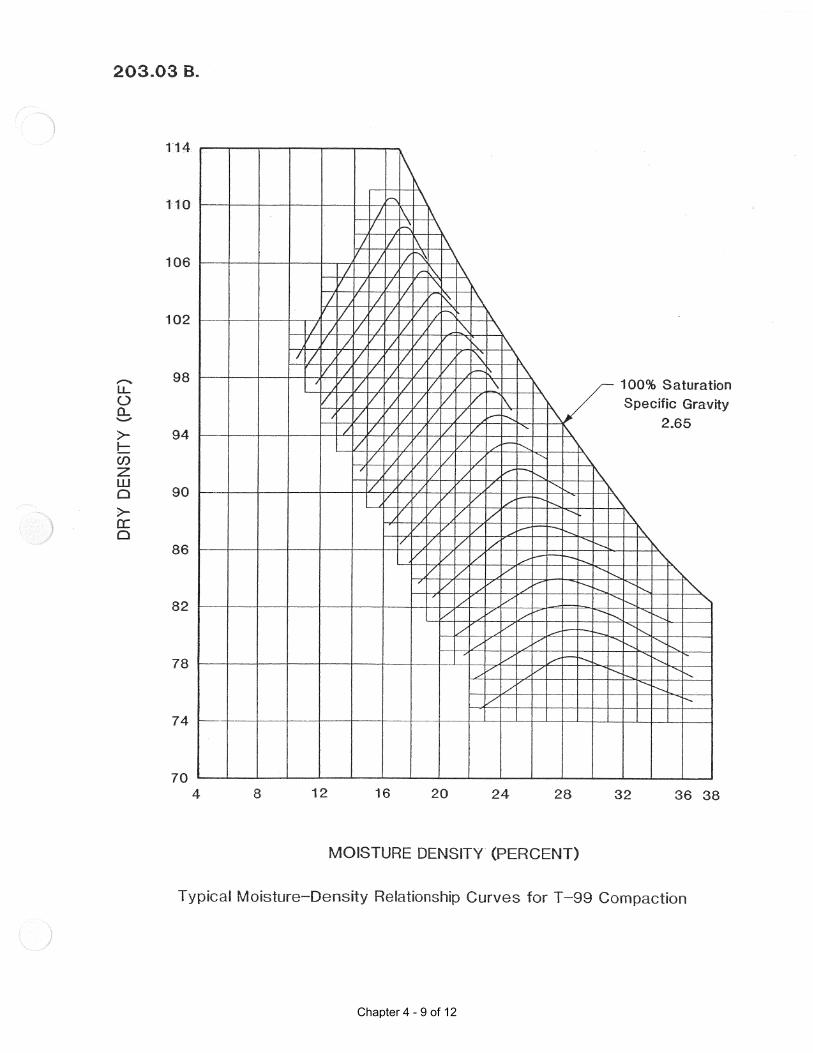
Chapter 4 - 9 of 12

Chapter 4 - 10 of 12

Chapter 4 - 11 of 12

Chapter 4 - 12 of 12

Chapter 5


2/22/2016
Steps of a Typical Project
1. Pre‐Construction – Recommendations are incorporated into plans and specifications for compaction method. Recommendations may be for T 99 or T 180. T 180 is the method to be used unless otherwise specified in the plans. Some plans in Eastern North Dakota, particularly in the Red River Valley require T 99. The soils report and recommendation may recommend areas along the project that need to be sub‐cut.
2. Engineers/Technicians familiarize themselves with the Plans, NDDOT Specifications and
Supplemental Specifications, Soils Reports, Field Sampling and Testing Manual, etc. before project begins.
3. Project bid and awarded. Contractor may hire subcontractor for earth work. 4. Contractor determines any borrow source needed for projects if the borrow source is not
listed in the plans. 5. District obtains sample of soil to run a multi‐point proctor test. Optimum moisture and
maximum dry density determined for each type of soil encountered on the project site. 6. Contractor begins dirt work/earthwork process. 7. Engineer’s main grading Inspector must inspect the work as it is being completed and be
alert to any changes in soil conditions. They are expected to be fully informed about the requirements and procedures relating to the project.
8. Engineer’s staff will randomly select locations and perform tests at the prescribed frequency
to ensure compaction is meeting requirements. (refer to the field sampling and testing manual)
9. If soil type changes a new proctor test will be run to determine the new/correct optimum
moisture and maximum dry density. At times a one‐point proctor may be used.
Chapter 5 - 1 of 8

Chapter 5 - 2 of 8
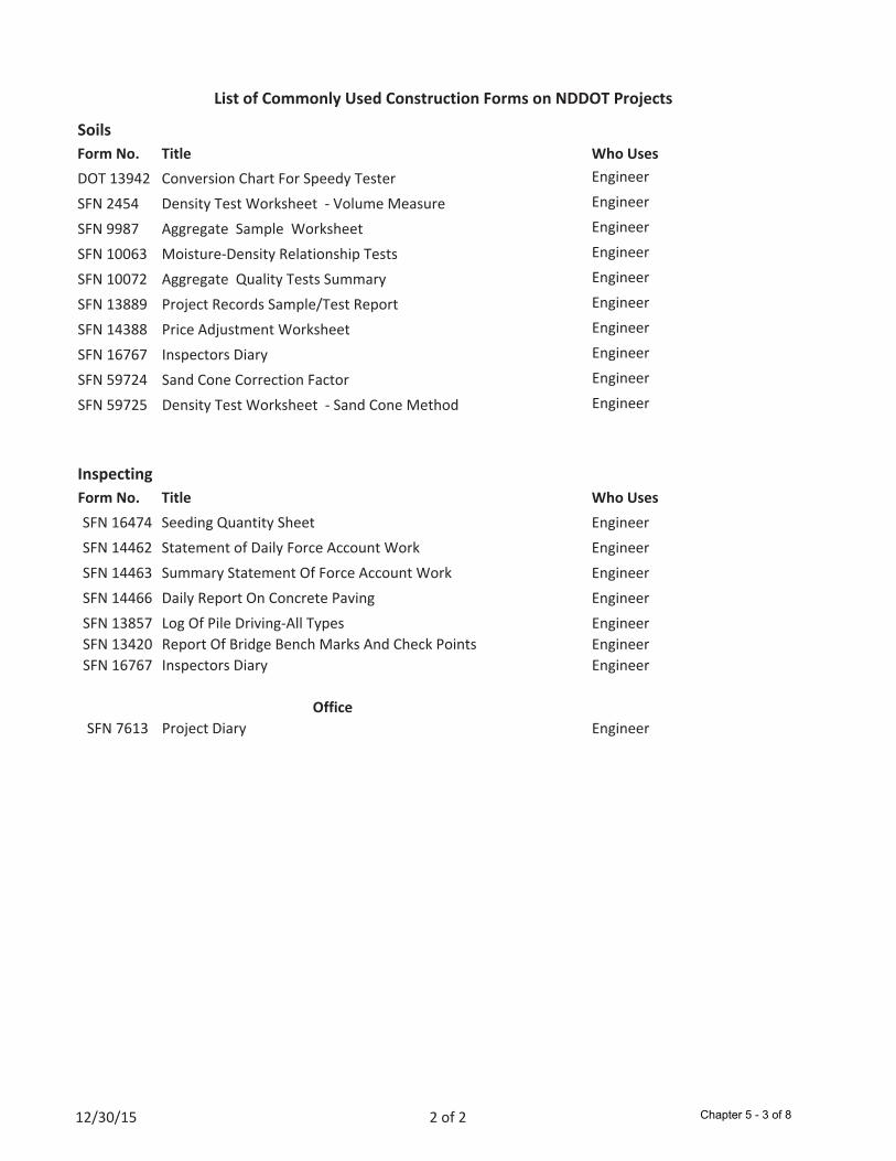
List of Commonly Used Construction Forms on NDDOT Projects
Form No. Title Who Uses
DOT 13942 Conversion Chart For Speedy Tester Engineer
SFN 2454 Density Test Worksheet Volume Measure Engineer
SFN 9987 Aggregate Sample Worksheet Engineer
SFN 10063 Moisture Density Relationship Tests Engineer
SFN 10072 Aggregate Quality Tests Summary Engineer
SFN 13889 Project Records Sample/Test Report Engineer
SFN 14388 Price Adjustment Worksheet Engineer
SFN 16767 Inspectors Diary Engineer
SFN 59724 Sand Cone Correction Factor Engineer
SFN 59725 Density Test Worksheet Sand Cone Method Engineer
Form No. Title Who Uses
SFN 16474 Seeding Quantity Sheet Engineer
SFN 14462 Statement of Daily Force Account Work Engineer
SFN 14463 Summary Statement Of Force Account Work Engineer
SFN 14466 Daily Report On Concrete Paving Engineer
SFN 13857 Log Of Pile Driving All Types Engineer
SFN 13420 Report Of Bridge Bench Marks And Check Points Engineer
SFN 16767 Inspectors Diary Engineer
SFN 7613 Project Diary Engineer
Office
Inspecting
Soils
12/30/15 2 of 2 Chapter 5 - 3 of 8

Chapter 5 - 4 of 8

Soils Terms
GLOSSORY OF TERMS
Page 1 of 3
Absorbed Water - Water that fills the voids of a soil. Atterberg Limits - Tests designed by A. Atterberg. Used to identify the limits at which a soil passes from a solid, semisolid, plastic, and liquid states. Atterberg Limits are the Plastic Limit, Liquid Limit and Shrinkage Limit. The Plastic Limit and Liquid Limit are used to determine the Plasticity Index. The NDDOT does not use the Shrinkage Limit. Capillary Action - The attraction of water to a surface which causes it to rise against the force of gravity through surface tension. Clay - An earth material with a particle size smaller than 0.002 mm but larger than 0.001 mm. Colloids - Earth material with very small particles, being anything smaller than 0.001 mm. Cohesive - Tending to stick together (Clay particles, negative particles attract to the positive ends of particles) Compaction - The reduction of voids in a soil mass. The densification of the soil mass by applying a force such as delivered by the rammer. Compaction Effort - The force applied to achieve compaction of a soil mass. In the laboratory, the rammer used in this test procedure produces the compaction effort. Compaction effort is increased by increasing the mass, increasing the distance the mass is dropped, increasing the number of drops or reducing the thickness of the layer being compacted. Compressibility - Able to be reduced in volume through compaction. Constant Mass - The point at which all free water has been removed from a soil. For the purposes of moisture content testing, constant mass is defined as when a dried soil specimen no longer loses mass in two successive weighing. Deflection - The amount of downward vertical movement of a surface due to the application of a load to the surface. Density - The mass of the soil divided by the volume. Dry Density - The density of the soil corrected for moisture content. Elasticity - Ability of soil to return to its original shape after having been deformed by a load for a short period of time. Entrapped Air - Air that is trapped within the soil. Friable - A non-cohesive material which crumbles readily.
Chapter 5 - 5 of 8

Soils Terms
GLOSSORY OF TERMS
Page 2 of 3
Homogenous - Of uniform structure and composition throughout. Hydrometer - A testing device used to measure the specific gravity of a liquid in which particles are either suspended or dissolved. Hygroscopic Moisture - Moisture still remaining in soil after it has been air-dried. Hydration - The incorporation of moisture. Liquid Limit - An Atterberg Limit. The moisture content at which a soil moves from a plastic to a liquid state. Maximum Density - The dry density corresponding to the peak of the moisture-density curve. The highest density that can be achieved for a particular soil using a particular compaction effort. Also referred to as “maximum dry density.” Maximum Dry Density - See “maximum density” Meniscus - The curved concave upper surface of a column of liquid in a tube. This concave surface is caused by surface tension. (Refer to Capillary Action.) Moisture Content - The ratio, expressed as a percentage, of the mass of the water in a given soil mass to the mass of the solid particles. The mass of the soil remaining after oven-drying is used as the mass of the solid particles. Moisture-Density Curve - A smooth line connecting the points obtained from this test procedure when plotted on a graph with moisture on the x-axis and density on the y-axis. Nonplastic - Not capable of being molded into a sustainable shape. Optimum Moisture Content - The moisture content corresponding to the peak of the moisture-density curve. The moisture content at which the maximum density can be achieved. Percent Density - The ratio expressed as a percentage of the dry density to the maximum Density Permeability - The rate at which water will flow or pass through the pores of soil. Percent Compaction - The ratio, expressed as a percentage, of the density of a soil to its maximum density. Plastic - Capable of being molded into a sustainable shape. Plastic Limit - An Atterberg Limit. The moisture content at which a soil moves from a semisolid to a plastic state.
Chapter 5 - 6 of 8

Soils Terms
GLOSSORY OF TERMS
Page 3 of 3
Plasticity - The property of a soil that allows it to be deformed beyond the point of recovery without cracking or appreciable volume change. Plasticity Index - A measure of the cohesive properties of a soil. Determined by subtracting the Plastic Limit from the Liquid Limit. Pulverize - The process to reduce soil mass into individual particles for testing purposes. Representative - A sample which possesses the same characteristics as the in situ material from which it was taken. Retained - Material fragments which do not pass through a sieve during sieving operations, but remain on the sieve surface. Shear Strength - The maximum resistance of a soil to shearing stress. It is the result of friction between the particles, and cohesion. Shrinkage Limit - An Atterberg Limit. The moisture content at which a soil changes from a solid to a semisolid. Shear - Failure in a soil parallel to the direction of applied force. Sieve - A frame enclosing a wire, cloth, or perforated plate used to separate materials by grain size. Silt - An earth material with a particle size smaller than 0.074 mm but larger than 0.002 mm. Soil - Any earthen material, excluding bed rock, composed of loosely bound mineral grains of various sizes and shapes, organic material, water and gases. Soil - Mineral particles which have been naturally degraded from mass rock. Soil Mechanics - The study of engineering properties and behavior of soils. Specific Gravity - The ratio of the weight in air of a specific volume of material to the weight in air of an equal volume of water, all at the same temperature.
Chapter 5 - 7 of 8

Chapter 5 - 8 of 8