soilpak - southern irrigators
TRANSCRIPT

SOILpak – southern irrigators - Readers’ Note This document is part of a larger publication. The remaining parts and full version of the publication can be found at:
http://www.dpi.nsw.gov.au/agriculture/resources/soils/guides/soilpak/south-irrig Updated versions of this document can also be found at the above web address. This document is subject to the disclaimers and copyright of the full version from which it is extracted. These disclaimers and copyright statements are available in the appropriate document at the above web address.

PPAARRTT BB.. QQUUIICCKK HHEELLPP GGUUIIDDEE
CChhaapptteerr BB11.. TTrroouubbllee-sshhoooottiinngg gguuiiddee
CChhaapptteerr BB22.. RReedduucciinngg wwaatteerrllooggggiinngg
CChhaapptteerr BB33.. MMaannaaggiinngg ccrruussttiinngg aanndd hhaarrddsseettttiinngg ssooiill
CChhaapptteerr BB44.. DDoo II hhaavvee aa ccoommppaaccttiioonn pprroobblleemm??
CChhaapptteerr BB55.. IIss mmyy ssooiill iiss aacciidd??
CChhaapptteerr BB66.. IIss mmyy ssooiill ssaalliinnee??
CChhaapptteerr BB77.. IIss mmyy ssooiill ssuuiittaabbllee ffoorr rriiccee ggrroowwiinngg??
CChhaapptteerr BB88.. IIss mmyy ssooiill ssuuiittaabbllee ffoorr ddiirreecctt ddrriilllliinngg??
CChhaapptteerr BB99.. IIss mmyy ssooiill ssuuiittaabbllee ffoorr rraaiisseedd bbeeddffaarrmmiinngg??
CChhaapptteerr BB1100.. MMaannaaggiinngg ppaaddddoocckkss wwiitthh ssooiill vvaarriiaattiioonn
CChhaapptteerr BB1111.. SSooiill ssuurrvveeyy ffoorr iirrrriiggaattiioonn ddeevveellooppmmeenntt oorr rreeddeevveellooppmmeenntt
CChhaapptteerr BB1122.. MMaannaaggiinngg rreecceennttllyy llaannddffoorrmmeedd aarreeaass
qquu
iicckk hh
eellpp

B1. Trouble-shooting guide
B1.1Southern Irrigation SOILpak
Chapter B1. Trouble-shootingguideAn ideal soil (Chapter A3) should supply the plants with adequatewater, oxygen, nutrients and support. When the soil does not providethese requirements there is a soil problem.
Irrigation in southern NSW has developed on soils which can havesevere limitations to crop growth under irrigated conditions. Commonsoil problems in southern NSW include:
• poor tilth
• inadequate infiltration
• poor internal drainage
• poor seedling emergence
• poor crop growth and yield
A soil problem may be due to:
• recent management — such as compaction, remoulding andsmearing when tilling a soil that is too wet
• a residual management problem — such as deep subsoil compactioncaused by landforming a moist clay soil
• a natural problem present at the time of European settlement — suchas salt left in the soil by an inland sea covering Australia 65 millionyears ago
To identify a soil problem that may be effecting you, examine the soiland crop/pasture performance in your paddock. Once the problem hasbeen identified, Tables B1–B5 will help you determine the cause of theproblem and direct your to chapters of the manual with more detailedinformation.
Table B1. Possible causes and signs of poor tilth
Problem Possible signs Possible cause Relevantchapters
POOR large clods • inadequate rolling/tillage C5, C8, E4TILTH to break down clods
• cultivation at incorrect C8 moisture content
• hardsetting, crusting, B3, C7, E2 sodicity

B1. Trouble-shooting guide
B1.2 Southern Irrigation SOILpak
Table B2. Possible causes and signs of inadequate infiltration
Problem Possible Possible cause Relevantsigns chapters
INADEQUATE low • hardsetting/crusting B3, C7, E1INFILTRATION porosity • sodicity C7, E1
hard • hardsetting/crusting B3, C7, E1surface,few cracks
dispersion • sodicity C7, E1
surface • sodicity B2, C7, E1poorly • compaction B4, C5, E3, E4drained • flat land/poor layouts B2, B12, C7,after E1irrigation/rainfall
Table B3. Possible causes and signs of poor internal drainage
Problem Possible Possible cause Relevantsigns chapters
POOR waterlogging • high subsoil density B4, C5, C6INTERNAL /poor aerationDRAINAGE • sodicity B2, C7, E1
Table B4. Possible causes and signs of poor seedling emergence
Problem Possible Possible cause Relevantsigns chapters
POOR surface poorly • sodicity C7, E1SEEDLING drained after • compaction B4, C5, E4EMERGENCE irrigation/ • unsuitable layouts B2, B12, E3
rainfall /irrigation design
dispersion • sodicity C7, E1
hard surface, • hardsetting/crusting C7, E2few cracks • sodicity C7, E1
too many large • hardsetting C7, C8, E2clods in • sodicity C7, E1seedbed • compaction B4, C5, E4
• tillage implement C8, E4 problems
slime present • algae B7, D2in rice bays • excessive plant E5
residues

B1. Trouble-shooting guide
B1.3Southern Irrigation SOILpak
Table B5. Possible causes and signs of poor crop growth and yield
Problem Possible Possible cause Relevantsigns chapters
POOR surface poorly • sodicity B2, C7, E1CROP drained after • compaction B4, C5, D4GROWTH irrigation/rain • poor layouts B9AND YIELD /irrigation design
hard dense • compaction and/or B4, C5, C8, E4subsoil smearing by
machinery
• sodicity C7, E1
dispersion • sodicity C7, E1
unusual leaf • poor nutrition E5colour • waterlogging, N B2, E5
deficiency• pH imbalance• disease, herbicide B5 damage
salt tolerant • salinity B6, C10weeds, risingwatertables

B1. Trouble-shooting guide
B1.4 Southern Irrigation SOILpak

B2. Reducing waterlogging
B2.1Southern Irrigation SOILpak
Chapter B2. Reducing waterloggingINTRODUCTION
Waterlogging in irrigated crop and pasture production causes pooraeration and is responsible for large yield losses. These losses are oftenunrecognised. Accessions to the watertable are also more likely.
Many of the soil types dealt with in this manual have poor internaldrainage (permeability). Therefore, particular attention must be paid tosurface drainage to reduce waterlogging and to achieve optimumyields. Good surface drainage removes surplus water from an area,avoiding excessive infiltration and surface ponding. Surface drainage iscontrolled primarily by slope, irrigation layout, design and structures.
When irrigating non-rice crops and pastures, water should notremain ponded for more than 12 hours. Yield losses from longerdurations of ponding are likely, especially for crops intolerant ofwaterlogging.
AVOIDANCE OF WATERLOGGING
Waterlogging can be reduced by:
• Development of a suitable irrigation layout
• Redevelopment of an unsuitable irrigation layout
• Use of raised beds
• Higher flow rates (water on and off quicker)
• Restriction of wheels of traffic to narrow laneways
• Irrigation scheduling
TYPE OF IRRIGATION LAYOUTä
ä
ä
ä
���������
��� ������������ �����
��� ���������������������������������������� ��!"
��� ��� ������������
Start here
#����������������������$%��&#��!�����������������������!���$'����� ���()*"
��������������"�#�������� ����������������������������������������������������������������
�����"
+��� ������������ �������������������,����������������������������������������,����,��%���
��������������������������*�
(����!����!������������ ����
-�.����������� ����������������� ������"
Figure B1. selection of irrigation layout
(������,�������
-���� ���� ��������/��������������������,��������
����

B2. Reducing waterlogging
B2.2 Southern Irrigation SOILpak
Border check irrigation layouts
The period of ponding, and therefore the degree of waterlogging, ina border check irrigation layout is controlled by:
• flow rate
• bay length
• slope
The combined effects of bay length and slope on the time ofponding is shown in Figure B2. As waterlogging increases with thetime of ponding, duration of ponding should be minimised to reducewaterlogging.
Figure B2. Time of ponding vs bay length (spring irrigation, cerealcrop, transitional red-brown earth)
Tim
e o
f po
ndin
g (
hour
s)
0�"��
0�"��
��"��
��"��
���"��
���"�� �� 1�� ��� 2��
Bay length (m)
Ñ
Ñ
Ñ
▲
▲
▲
▲
▲
Ñ
����������� ���������
����������� ���������
����������� ���������
����������� ���������
��� ��������������������������
○
○
○
○
○
○
○
○
○
○
○
○
○
○
○
○
○
○
○
○
○
○
○
○
○
○
○
○
○
○
○
○
○
○
○
○
○ ○
Flow rateFlow rate for a border check layout should be 1.5–2 litres per
second (L/s) per metre of bay width. Table B6 gives flow rates fordifferent bay widths based on 1.75 L/s/m of bay width.
Table B6. Flow rates for border check irrigation (based on flow rate of1.75 L/s/m of bay width)
Bay width (m) Flow rate required (ML/day)
20 3.040 6.060 9.180 12.1
Bay lengthTo minimise waterlogging, bay length should not exceed 400 m.
Figure B2 shows that bay length has a large impact on period ofponding (waterlogging), especially at lower flow rates.

B2. Reducing waterlogging
B2.3Southern Irrigation SOILpak
Slope of baySlope will affect the surface drainage of the bay and therefore is an
important determinant of waterlogging. The optimum slopes for aborder check irrigation layout range from 1:500–1:1500.
Slopes flatter than 1:750 may have slight hollows or depressions inwhich water may lie after the bay is drained, thus contributing towaterlogging. This is a consequence of variation in landformingaccuracy, and is difficult to avoid. Slopes steeper than 1:750 are bestsuited to crops other than rice. Successful irrigation of winter crops andpastures can be obtained on slopes of 1:1000.
Suitable operation of a border check irrigation system can beobtained at slopes as low as 1:1500. Slopes flatter than about 1:1500should be considered for bedfarming (see Chapter B9: Is my soilsuitable for raised bedfarming?).
Contour irrigation layouts
Contour irrigation layouts are used for rice and therefore for otherland uses in rotation with rice (pasture and winter crops). It is importantthat the layout allows fast drainage from the bay. This will reducewaterlogging in the winter crops and pastures, and increaseproductivity. It also reduces the occurrence of a wet rice harvest andassociated soil compaction.
Flow rateWhen growing non-rice crops, high flow rates in contour bays are
ideal for reducing time of ponding and waterlogging. As bays becomelarger, greater flow rates are required to reduce waterlogging.
For example, a three-hectare bay would require a flow rate of14 ML/day to achieve bay fill in 4–6 hours on a heavy clay soil.
Bay sizeOptimum size of a contour bay ranges from 3–6 ha. This allows
good water control and efficient use of machinery. The maximum sizeof a contour bay for winter cereal and pasture production is about threehectares. Rotation crops and pastures grown in bays larger than thisrequire high flow rates to prevent waterlogging, and these rates may bedifficult to achieve. Contour bays should be no longer than 400 mbetween outlet points for best drainage.
SlopeThe optimum slope of a contour bay for rice production is 1:1000–
1:1200, but they can be flatter. Reduced waterlogging in rotation cropsmust be achieved through management of flow rate and choice of baysize.
Contour intervalA contour interval of 5 cm between banks is ideal for rice, and
should no more than 7.5 cm. Contour intervals of this order ensure aneven depth of water over the bay.
DrainageToe furrows should be kept clean and continuous. Even a small
ridge of soil in or beside the toe furrow will impede drainage. In bayswith depressions that collect water, a shallow drain should be dug fromthe depression to the toe furrow, to assist drainage.

B2. Reducing waterlogging
B2.4 Southern Irrigation SOILpak
Raised beds and controlled traffic
Bedfarming is a type of furrow irrigation layout. The crop is grownon a raised bed and irrigated via furrows located either side of the bed.Ideally irrigation water moves laterally from the furrow through the bedby “subbing” (soaking up water from the furrow to the top and middleof the bed against gravity). This layout reduces waterlogging becauseflooding over the soil surface is avoided. Since the bed is raised abovethe furrow, excess water in the bed may drain back into the furrow toprevent waterlogging.
Restriction of wheel traffic to the furrows also reduces thewaterlogging problems associated with compacted soil.
Suitable soil types for raised bedsSee B9: Is my soil suitable for raised bedfarming?
SlopeRaised beds provide the best irrigation layout, for suitable soil types,
where paddocks are relatively flat. Raised beds are suited to flattergrades, ranging from 1:1000–1:2500.
Bed geometryRaised beds are normally 1.5–2.0 m wide, allowing a bed top width
of 1.0–1.5 m. Optimum bed width varies with soil type. Acceptablesubbing can be achieved in 1.8–2.0 m wide beds on a self mulchingclay. Some red-brown earths and non self-mulching clays require bedwidths of 1.0–1.5 m for adequate water entry. On all soil types, the rateof subbing will be reduced by bed-shoulder compaction if machinerywheels are too wide.
The height of beds ranges from 15–20 cm, but varies with furrowlength and slope. For flatter grades and longer furrows, the height ofbeds must be increased to prevent waterlogging.
Furrow lengthThe optimum length of the furrow depends on soil type and slope.
Shorter furrow lengths are preferred on lighter soils to prevent over-watering the top end of the paddock. On heavy soils, furrow lengths ofup to 800 m have been used after landforming. Shorter furrow lengthsare also required as slope becomes flatter. This is necessary to preventover-watering and waterlogging of the beds.
Irrigation schedulingIrrigation scheduling is recommended to match water application to
plant needs. This aims to prevent both drought stress and waterloggingof the crop (see Chapter E7: Irrigation scheduling).

B3. Managing crusting and hardsetting soil
B3.1Southern Irrigation SOILpak
Chapter B3. Managingcrusting and hardsetting soilINTRODUCTION
Crusting and hardsetting is evident in soils with a high content offine sand and/or silt (loamy soil) and low organic matter levels.A crusting or hardsetting topsoil can be recognised as a hard surfacelayer, showing very little structure and few shrinkage cracks. Crusts arerecognised as a hard surface layer up to 1 cm thick. Hardset layers aregreater than 1 cm thick, and usually the entire topsoil sets hard.
Crusting is common on loamy soils.
Crusting and hardsetting can occur naturally on any soil but will beworse when:
· surface soil has a loam texture (high content of fine sand and/or silt)
· surface soil is low in organic matter
· soil structure has been damaged by cultivation, particularly whenthe soil was too dry
· soil is not protected from raindrop impact by plants or stubble
· surface soil is sodic
PREVENTING AND REPAIRING SOIL CRUSTS ANDHARDSETTING LAYERS
Create surface cover
Cereal crops and pasture grasses, with their fibrous root systems,create pathways for water flow and root growth. This improves thestructure of the topsoil and prevents hardsetting and crusting. Organicresidues also help to overcome hardsetting and crusting by improvingaggregation.
Raindrop impact and the flooding of the soil during irrigation, candamage the structure of loam topsoils. By retaining stubble or goodplant cover, structural damage leading to the formation of crusts andhardset layers may be avoided.

B3. Managing crusting and hardsetting soil
B3.2 Southern Irrigation SOILpak
Increase soil organic matter levels
Soil management should aim to maintain soil organic matter levelsabove 2%. Soil organic matter can be increased by reducing the numberand severity of cultivations, maintaining plant cover, and retainingstubbles. These are all good conservation farming practices. Ploughingin ‘green manure crops’ may also be used to improve the organic mattercontent of the topsoil, although this practice tends to disrupt continuousvertical macropores in the topsoil.
Apply gypsum to sodic topsoils
Topsoils with an exchangeable sodium percentage greater than 6, oran dispersion score greater than 6, are sodic and prone to dispersion(see Chapter C7: Slaking and dispersion). Dispersion leads to crustingor hardsetting of the topsoil. Sodic topsoils would benefit from anapplication of gypsum prior to sowing (except rice) to reduce crustingor hardsetting, and improve water entry and seedling emergence.
Tillage
Where the subsoil is a cracking clay, crusting and hardsettingproblems may be ameliorated by mouldboard ploughing. This shattersthe crust or hardset layer, and brings subsoil clay to the surface topromote cracking in the topsoil. Attention must be paid to the depth ofsubsoil to ensure depth of ploughing is sufficient to bring swelling clayto the surface. This technique is suitable for soils with a non-sodicsubsoil. If sodic clay soil is brought to the surface, problems may beexacerbated.
Deep ripping and chisel ploughing are options to break a crust orhardset layer and improve water entry. A crust breaking roller (spikedroller) is also an effective implement for breaking a crusted layer andimproving seedling emergence.
Minimising tillage will also help to prevent crusting and hardsetting.Only till the soil when there is no other option and at a water contentjust below the plastic limit.

B4. Do I have a compaction problem?
B4.1Southern Irrigation SOILpak
Chapter B4. Do I have acompaction problem?INTRODUCTION
Compaction occurs when soil is compressed into a smallervolume so that its density is increased and air filled porosity isdecreased. This results in poor internal drainage and resistance to rootgrowth. Compaction is a consequence of machinery or animal traffic onwet/moist soil. Compaction can cause serious yield losses if notrecognised and treated quickly. Compaction is often associated withremoulding of soil, which is the disruption of continuous soil poreswithout an increase in bulk density of the soil.
IDENTIFICATION OF SOIL COMPACTION
Methods for recognising compaction problems are:
Paddock history
Any operation of machinery or grazing of stock on wet soil is likelyto cause some soil compaction. Severe damage is usually associatedwith wheel ruts caused during a wet harvest, and plough pans causedby tillage above the optimum moisture content (plastic limit).
Waterlogging
Waterlogging may be the result of poor internal drainage after soilhas been compacted. Stunted plant growth with yellowing leaves is asymptom of waterlogging and may indicate compaction.
Irrigation interval
A forced decrease in irrigation interval may also indicatecompaction. Compacted soil stores less water for plant uptake. Thishappens because soil porosity is reduced and because plant roots havegreater difficulty extracting the water that is potentially available.Irrigation water must be added to the soil more often to satisfy plantwater requirements
Soil examination
Examining the soil is a good way to diagnose compaction andallows the severity of the problem to be determined. Platey aggregatesand/or restricted root growth suggest that compaction has occurred.Knowing the soil group will also indicate the likelihood of compaction.As an example, self-mulching clay soils are more prone to compactionthan the non self-mulching clays, since the latter are more dense andstructurally poor in the first place.
In order to assess the severity of compaction in a paddock, choosethe best, average and worst yielding areas for examination. Theprocedure for assessing the degree of compaction is presented inChapter C5: Soil structure, and gives an indication as to whether a soilis severely compacted or is well structured soil.

B4. Do I have a compaction problem?
B4.2 Southern Irrigation SOILpak
REPAIRING COMPACTED SOIL
Compacted soil can be repaired by the following methods:
• Growing a crop to dry the soil and promote cracking of thecompacted layer
• Deep ripping the soil at an appropriate soil moisture content toshatter the compacted layer
Drying the soil
Compaction in self-mulching clays (cracking clay) can be repairedby growing a crop to dry the soil and promote cracking of thecompacted layer. This method will not be successful in non self-mulching clays and red-brown earths, because there is insufficientcracking clay in them to create large cracks.
To ensure successful amelioration of compacted layers, thefollowing points should be considered:
• Winter cereals are usually best suited to drying a soil profile.
• Cracks will form when clay soils dry out due to the swelling andshrinking of the clay.
Techniques for effective drying and opening of clay soils include:
• Sow a winter cereal crop as normal. The crop should be adequatelyfertilised and sown on time.
• Crop irrigation should cease so that the soil is dry to the compactiondepth at harvest.
Deep ripping
Deep ripping is a short term remedy which will break the compactedlayer, allowing air, water and roots to penetrate the soil to a greaterdepth. Depth to compaction layer should be checked (see Chapter C2:Soil pit digging — where, how and why?), as well as soil moisturesuitable for cultivation at that depth (see Chapter C8: Assessing soilmoisture). This will ensure that tillage is carried out at a depth adequateto break the compacted layer, and at the correct moisture content toprevent further structural damage (smearing).
Cultivation should not invert the soil, which would bring sodicsubsoil to the surface. The soil should be deep ripped to about 10 cmbelow the compacted layer to allow for variation in depth of compactedlayer across the paddock. See also Chapter C5: Soil structure, andChapter E5: Improving soil structure by crop rotation.
AVOIDING COMPACTION
Avoiding compaction problems tends to be much less expensivethan repairing compaction. Aim to achieve the following:
• where possible avoid driving on, or tilling soil, that is wetter thanthe plastic limit (see Chapter C8)
• if driving on wet soil is unavoidable, minimise the damage byrestricting the wheels of farm machinery to narrow laneways.Consider the use of guidance systems for farm machinery
• be aware that heavy stocking rates of livestock can aggravatecompaction, especially if the soil is wet

B5. Is my soil acid?
B5.1Southern Irrigation SOILpak
Chapter B5. Is my soil acid?Most crops and pasture plants grow best in soils with pH 5–7.
Most can tolerate soil conditions where pH is more than 7 (slightlyalkaline) better than where pH is less than 5 (strongly acid). Low pH isa more widespread problem than high pH. A low pH problem can bediagnosed in the following ways:
Paddock history
A history of clover dominant pastures, rice, intensive cropping orhigh nitrogen applications may contribute to a reduction in soil pH. Iflegumes (clovers, lucerne, soybeans) show symptoms such asyellowing of leaves, poor root growth and poor nodulation, soil aciditymay be a problem.
As pH decreases, toxic elements such as aluminium andmanganese become more available, and nutrients such as phosphorusand molybdenum become less available. Symptoms of toxicity ordeficiency of these elements are a telltale sign.
Soil type
Coarser textured (sandier) soils are more likely to be acid.Therefore sandhill soils and red-brown earths are likely to develop soilacidity faster than other soil types.
Soil test
Soil pH may be tested in either a calcium chloride solution (pHCaCl
)or in water (pH
water). The test in calcium chloride is more representative
of the acidity/alkalinity a plant experiences in the soil. A pHCaCl
of lessthan 5 indicates that the soil is strongly acid, and growth of many cropspecies is likely to be less than optimal.
A reduction in pH also makes aluminium more available to plants.If the exchangeable aluminium percentage (Al%) is greater than 5%,then plant growth is likely to be reduced due to aluminium toxicity.Furthermore, as soil salinity increases, plant tolerance to aluminiumtoxicity decreases. Therefore, on severely saline soils (ECe more than6 dS/m) aluminium toxicity may be evident where the exchangeableAl% is less than 5%.
MANAGING ACID SOILS
The following courses of action can be taken to improve plantproduction where pH
CaCl is less than 5:
• lime application to increase soil pH
• choose acid-tolerant crops
Acidity (low soil pH) develops first at the soil surface andover time moves down into the lower layers of the soil. If soilacidity is allowed to develop, and soil is not limed, thesubsoil may become acid. Subsoil acidity is difficult andcostly to overcome.
B5. Is my soil acid?
B5.2 Southern Irrigation SOILpak
LIME APPLICATION
The most effective way to ameliorate acid soils is to apply lime(calcium carbonate). The actual rate will depend on pH, exchangeablealuminium present and soil texture.
When liming soil, aim to increase the pHCaCl
to at least 5.2. Soiltexture should be determined to establish the lime application rate.
To increase soil pH by 0.5, the following lime application ratesshould be used: (Fenton, Helyar, and Orchard, Agfact AC.19)
• 2.5 t/ha for a clay soil
• 1.7 t/ha for a silty clay loam
• 1.3 t/ha for a sandy clay loam
• 1.0 t/ha for a sandy loam
A faster and more effective change in pH will occur if the lime isincorporated into the soil rather than broadcast.
USE OF ACID-TOLERANT CROPS
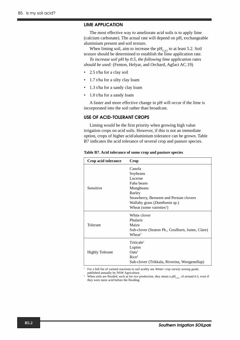
Liming would be the first priority when growing high valueirrigation crops on acid soils. However, if this is not an immediateoption, crops of higher acid/aluminium tolerance can be grown. TableB7 indicates the acid tolerance of several crop and pasture species.
Table B7. Acid tolerance of some crop and pasture species
Crop acid tolerance Crop
CanolaSoybeansLucerneFaba beans
Sensitive MungbeansBarleyStrawberry, Berseem and Persian cloversWallaby grass (Danthonia sp.)Wheat (some varieties1)
White cloverPhalaris
Tolerant MaizeSub-clover (Seaton Pk., Goulburn, Junee, Clare)Wheat1
Triticale1
LupinsHighly Tolerant Oats1
Rice2
Sub-clover (Trikkala, Riverina, Woogenellup)
1 For a full list of varietal reactions to soil acidity see Winter crop variety sowing guide,published annually by NSW Agriculture.
2 When soils are flooded, such as for rice production, they attain a pHCaCl
of around 6.5, even ifthey were more acid before the flooding.

B6. Is my soil saline?
B6.1Southern Irrigation SOILpak
Chapter B6. Is my soil saline?INTRODUCTION
The development of irrigation in southern NSW has seenagricultural land use change from extensive semi-arid grazing toirrigated land. While irrigation has improved the productivity of land, itmay also lead to the development of shallow watertables andsubsequent soil salinisation. Soil salinity reduces the productivity ofagricultural land and substantial yield losses can occur before definitesigns of salinity become visible. Therefore it is important to recogniseand monitor soil salinity on your farm.
Salinity refers to an accumulation of salt in the plant root zone or onthe soil surface. It usually occurs as a result of groundwater rising towithin two metres of the soil surface, resulting in a concentration of saltin the root zone as moisture is drawn into the surface soil by capillaryaction. This chapter described some of the diagnostic tools that areavailable to recognise and prevent soil salinity problems. Proceduresfor monitoring groundwater, testing water quality and soil salinity aredescribed below.
Where the volume of irrigation water plus rain exceeds the amountof evaporation and transpiration by plants, then seepage intogroundwater occurs. This process is known as groundwater rechargeand may cause watertables to rise. Rises may also be caused by thelateral movement of groundwater from surrounding areas. Watertablelevels can drop where groundwater is pumped for irrigation or is usedby deep rooted plants.
CAUSES OF SALINITY
Water added to the soil as rainfall or irrigation can drain from thesurface before soaking in, can be used by plants or evaporate from thesoil. However, water in excess of plant needs or evaporation drainsbelow the root zone to the watertable. Farming methods that result inexcessive irrigation water draining through the soil have beenresponsible for much of the increase in watertable heights in southernNSW.
As watertables rise, the salts that naturally occur in the soil aredissolved in the groundwater. When the watertable rises to withinapproximately two metres of the soil surface, water can move into theplant root zone by capillary rise. Salt becomes concentrated in the rootzone as water evaporates or is taken up by plants. Soil salinity increasesas this process continues.
WATERTABLE MONITORING
Testwells and piezometers
Groundwater within two metres of the soil surface can rise further upthe soil profile into the plant root zone through capillary action. Thismay lead to waterlogging and an accumulation of salt in the root zone.In sloping paddocks, the groundwater may move laterally and seep intolocal drains, creeks and rivers. The salt within this drainage waterlowers the quality of the water and may cause problems downstream.Therefore groundwater monitoring is important.

B6. Is my soil saline?
B6.2 Southern Irrigation SOILpak
There are two approaches to groundwater monitoring:
TestwellTestwells are made up of a length of slotted pipe 3–4 m placed in anaugered hole. They measure the free water depth to the local watertablebelow a paddock. Testwells to measure watertable depth can highlightpotential salinity hazards in a particular area. The Salt Action IrrigationSalinity Field Kit manual provides instructions required to constructand install a testwell. It also presents information regarding themeasurement of watertable depth and the interpretation of thesemeasurements.
PiezometerA piezometer is a tube where the slotted section is inserted intothe aquifer. Water moves from the aquifer into the tube through theslotted section of the tube. The height to which the water rises is ameasure of the pressure of the groundwater in that aquifer. If theaquifer is not confined by rock or dense soil, the level of water in thepiezometer will be equivalent to the depth of the local watertable.Piezometers are used to monitor changes is groundwater pressure levelsto a depth of 8–30 m.
The placement of piezometers and testwells at different depths willprovide information about trends in groundwater movement whenmonitored over time.
Quality of the water in piezometers and testwells should be tested, todetermine its salinity and sodicity hazard (see Salinity Field Kitmanual).
The quality of information from testwells and piezometers isstrongly influenced by how well the tubes are installed. For example, ifsoil on the sides of the excavated holes is compacted and/or smeared,water movement is likely to be very different to that occurring inundisturbed soil. Therefore it is essential that the installations be set upprofessionally.
QUALITY OF IRRIGATION WATER
The quality of all water used on the farm should be monitored toprevent the possibility of salts in water damaging plants and soil:
• saline water for irrigation may increase soil salinity, with thelikelihood of reduced yields and death of plants
• sodic water could result in sodium accumulating in the soil, causinga decline in soil structure
The Salinity Field Kit provides equipment and instructions for:
• sampling both surface and groundwater
• measuring the salinity of water samples
• determining the suitability of water for irrigation of specific cropsand pastures
To actively monitor and assess water quality on your farm, seePart 1: Water Sampling and Testing Water Salinity in the Salinity FieldKit manual.

B6. Is my soil saline?
B6.3Southern Irrigation SOILpak
Water salinitySalinity guidelines for irrigation water are summarised in Table B8
(page B6.6). They apply to water from any source. The soil salinitylimits for two levels of production losses for the main crops and pastureplants grown in the Riverina are shown.
Sodium hazardSoil structural stability may decline if the irrigation water is sodic
leading to surface crusting, poor water infiltration, low soil workabilityand muddy irrigation water. Sodium adsorption ratio (SAR) is a ratiofor irrigation waters and soil extracts used to express the relativeactivity of sodium ions (compared to calcium and magnesium ions) inexchange reactions with soil. Exchangeable sodium percentage (ESP)of the soil increases as the SAR of water passing through it becomesgreater. SAR of irrigation water should be kept below about 3 to avoidsuch problems
SAR is calculated as follows (in units of cation concentrationsor Meq/L):
SAR = (sodium concentration)
square root[(calcium concentration +magnesium concentration)/2]
As the SAR increases, the need for higher water salinity alsoincreases to maintain good soil structure that permits leaching.Irrigators whose water is low in salinity and high in sodium should seekmanagement advice from NSW Agriculture to minimise adverseimpacts on the soil.
SOIL SALINITY
Recognising salinity symptoms in the field
It may be difficult to recognise salinity problems in the paddockbecause plants often respond to excess salt in the same way they wouldrespond to other problems, such as water stress. There may be noobvious plant symptoms or signs of salt on the soil surface. Plant yieldsmay decline by up to 30% before signs of salinity become evident.
Early visible signs of salinity in the paddock include:
• poor crop growth
• increasing numbers of salt tolerant weeds such as couch and barleygrass
• development of grass dominant pastures - legumes are moresusceptible to high salinity than grass species
• prolonged wetness in patches
• unusually friable soil structure in low-lying areas
Severe visible symptoms of salinity include:
• bare salt encrusted soil surface
• white crystals, that are salty to taste, found on dry soil surface
• settling of suspended clay particles to give unusually clear water inpuddles or drains
• dominance of salt tolerant plants

B6. Is my soil saline?
B6.4 Southern Irrigation SOILpak
• greasy looking black patches, due to dispersion of organic matterunder high pH conditions, caused by the presence of bicarbonatesalts
• death of trees in surrounding areas
• total crop failure — germination is slow and plants grow poorly
• leaves appear smaller and darker in colour than normal
• marginal and tip burning of leaves, followed by yellowing andbronzing
Laboratory testing for soil salinity
To test a soil for salinity, a sample of soil is mixed with water and anelectric current is passed between two electrodes placed in the solution.The greater the salt concentration, the greater the current(conductivity). If no salt is present, very little electric current passes.There are two methods of measuring soil salinity:
Electrical conductivity of the saturated paste extract (ECe)The most accurate way of preparing the soil sample is to make asaturated paste. This involves the addition of distilled water to a soilsample until a characteristic sticky point is reached. A suction filter isthen used to extract a sufficient amount of water to perform anelectrical conductivity (Ec
e in dS/m) measurement. The advantage of
this method is that it is related to the water-holding capacity of the soiland thus is representative of what a plant root would experience.Unfortunately, this saturation extract method is tedious and timeconsuming to carry out.
Electrical conductivity of the 1:5 soil:water extract (EC1:5)A simpler and more commonly used approach is to mix the soil withfive times its weight of distilled water. Salinity is estimated bymeasuring electrical conductivity of this 1:5 soil:water suspension(EC
1:5 in
dS/m). However, this procedure does not take into account the
effects of soil texture – the readings from different soil types cannot becompared directly. Another possible problem is that in soil withsignificant amounts of gypsum, EC
1:5 will be over-estimated.
Monitoring Soil Salinity on your farm
Soil salinity on the farm can be measured by a field test (see ChapterC10: Soil salinity testing in the field). For this test 1 part of soil is addedto 5 parts water, and the salinity of the resulting solution is measuredusing a portable (hand held) EC meter. This result is then multiplied bya conversion factor depending on the soil texture, and the actual soilsalinity (EC
e) found.
Some laboratories use units other than dS/m (deciSiemens permetre) as salinity units. Two commonly used conversion factors are asfollows:
1 dS/m = 1000 mmS/cm (EC units) = 640 ppm (mg/kg)
Indirect methods — Electromagnetic induction(EM) devices
Electromagnetic induction (EM) devices rapidly estimate soilconductivity in the field by measuring the ease with which amagnetically-induced current passes through the soil.
EM instruments used for measuring soil conductivity include theEM38, EM31 and EM34. They are useful for describing apparentelectrical conductivity (EC
a) across paddocks. Each site requires
B6. Is my soil saline?
B6.5Southern Irrigation SOILpak
ground truthing because of variation in some soil factors, such as watercontent and clay, that also affect apparent conductivity.
These instruments monitor apparent conductivity at different depthsof the soil:
• the EM38 best describes conductivity within the root zone (to adepth of about 1–2 m)
• the EM31 is used for deeper subsoil studies of shallow aquifers anddeeper watertables (to a depth of approximately 3.5–7 m)
• the EM34 measures conductivity to depths ranging from 7–30 m,and is used mainly for catchment scale surveys of soil salinity.
Management options where soil salinity is diagnosed
Options to consider if the soil is saline, or about to become so, include:
• Minimise leakage from channels and dams
• Avoid bare fallows
• Schedule irrigations according to actual crop requirements, andapply water in a way that minimises deep drainage losses (fastwatering on and off).
• Groundwater pumping and recycling (the water can be used forirrigation if of sufficient quality).
• Planting of deep-rooted perennial plants such lucerne and trees inrecharge zones
• Where sodic groundwater is added to the soil, gypsum may have tobe applied to prevent the soil from dispersing when it rains.
Land management and monitoring
The soil salinity information collected on your farm can be used tomake land management decisions. The Salinity Field Kit manualpresents four land use classes based on differing levels of soil salinity.The appropriate management strategies for each class of land ispresented in the manual.
For suggestions about land management techniques appropriate forthe level of soil salinity on your farm, see Part 4: Land Managementand Monitoring in the Salinity Field Kit manual.

B6. Is my soil saline?
B6.6 Southern Irrigation SOILpak
Table B8: Tolerance of Crops and Pastures to water salinity and rootzone soil salinity(in decisiemens per metre, dS/m)
WATER SALINITY LIMITS for flood irrigation
Soil Type Well Drained Moderate to Slow Very Slow ROOT ZONESoils Draining Soils Draining Soils SOIL SALINITY
Yield Reduction Up to 25% Up to 25% Up to 25% Up to 25%10% 10% 10% 10%
Pasture LegumesWhite Clover 1.2 3.1 0.8 2.0 – – 1.2 3.1Sub Clover 1.2 3.1 0.8 2.0 0.4 1.0 1.2 3.1Strawberry Clover 2.1 4.0 1.4 2.6 0.7 1.3 2.1 4.0Lucerne (most varieties) 2.0 5.4 1.3 3.5 – – 2.0 5.4Lucerne (salt tolerant varieties) 3.6 5.9 2.4 3.9 – – 3.6 5.9Berseem Clover 6.0 18 4.0 12 2.0 6.0 6.0 18
Pasture GrassesPaspalum 2.0 4.6 1.3 3.0 0.6 1.5 2.0 4.6Phalaris 4.2 8.0 2.8 5.3 1.4 2.6 4.2 8.0Perennial Ryegrass 5.6 8.9 3.7 5.8 1.8 2.9 5.6 8.9Tall Wheatgrass 7.5 13.3 5.0 8.8 2.5 4.4 7.5 13.3Puccinellia 16 22 10.6 15 5.3 7.3 16 22Saltbush 12 20 8.0 13 4.0 6.6 12 20
Winter CropsFaba Beans 1.8 4.0 1.2 2.6 – – 1.8 4.0Oats 5.0 6.3 3.3 4.2 1.7 2.1 5.0 6.3Wheat 6.0 9.5 4.0 6.3 2.0 3.1 6.0 9.5Canola 6.5 11 4.3 7.3 2.1 3.6 6.5 11Barley 8.0 13 5.3 8.6 2.6 4.3 8.0 13
Summer CropsRice – – – – 1.0 1.7 3.0 5.1Maize 1.7 3.8 1.1 2.5 0.6 1.2 1.7 3.8Grain Sorghum 1.0 1.5 0.7 1.0 0.3 0.5 1.0 1.5Soybeans 2.0 2.6 1.3 1.7 0.6 0.8 2.0 2.6Sunflowers 5.5 6.5 3.6 4.3 – – 5.5 6.5Millet 6.0 9.0 4.0 6.0 2.0 3.0 6.0 9.0

B7. Is my soil suitable for rice growing?
B7.1Southern Irrigation SOILpak
Chapter B7. Is my soilsuitable for rice growing?INTRODUCTION
Potentially, rice growing can make considerable contributions torising watertables and subsequent salinisation of soil. To ensuresustainable rice production in southern NSW, growers aim to use lessthan 15–16 ML/ha per season, depending on weather conditions duringthe particular season. Where rice water use is greater than 16 ML/ha, itis likely that excessive water has drained below the root zone and to thewatertable. Rice growers can either grow rice only on suitable soils thathave minimal water losses, or they can amend the soil to reduce itspermeability.
SOIL TYPE SELECTION FOR RICE FARMING
Soil types most likely to restrict water losses in rice are those with ahigh proportion of dispersive clay in the soil profile. In general, the bestsoils for rice growing are:
• non self-mulching clays
• sodic transitional red-brown earths
More specific criteria, other than soil type, must be met for a soil to beapproved for rice growing. Soil classification criteria differ slightlybetween the Murray and Murrumbidgee regions, but the generalrequirement for both areas is a specific depth of heavy and/or mediumclay in the soil profile. The criteria for the Murray irrigation districts areoutlined in Table B9, with those for the Murrumbidgee in Table B10.
Table B9. Rice soil suitability criteria for the Murray region.
Rice growing category Depth of continuous medium or heavy clayin top 3.6 m of soil
suitable for rice under >3.0 mcontinuous rotation
marginal for rice growing 2–3 m(1 crop every 4 yrs) (minimum is 2 m in the top 2.5 m of soil)
Source: Murray Irrigation Limited Rice Growing Policy for 1998–99
Table B10 Rice soil suitability criteria for the Murrumbidgee region.
Rice growing category Depth of continuous medium to heavy clayin top 3.5 m of soil
suitable for rice under > 2.0 m where a sodic heavy clay B horizon iscontinuous rotation present from 0.1 to 0.6 m
OR> 3.0 m if there is no low permeability B
horizon present
Source: Dept. of Land and Water Conservation recommendations for 1998–99
The classification ‘marginal for rice growing’ is no longer used inthe Murrumbidgee region.

B7. Is my soil suitable for rice growing?
B7.2 Southern Irrigation SOILpak
To assess whether your soil is suitable for rice growing soil surveysmust be carried out. In Murray Irrigation Limited’s area, new rice land,land previously classified as marginal and land previously unclassifiedby grid drilling, will all require electromagnetic surveying (EM31), aswell as proof boring.
In the remaining areas, soil suitability is determined either by griddrilling or by EM surveying, with proof soil texture assessments carriedout on the bore samples by accredited operators.
OTHER METHODS TO REDUCE WATER LOSSES IN RICE
Puddling
Puddling is a technique where a flooded soil is rotary hoed toincrease the soil strength and density at the depth of hoeing. Thisreduces the number of pores capable of transmitting water andtherefore deep drainage losses. Accessions to the watertable areminimised. The soil is flooded for a couple of days until it is properlywetted, and then rotary hoed while there is about 2 cm of free water onthe surface. A front wheel assist tractor is almost essential, and therotary hoe should cover the wheel tracks.
Guidelines for puddling were developed by CSIRO at Griffith, anddetails are given in Table B11.
Soil compaction
A method of compacting soils for rice by using a 30 t roadcompaction machine has been tested in the Murray Valley. Whilst thismethod does appear to have reduced water losses, it cannot berecommended at this stage because the effects on other crops andpastures grown in the compacted land have not been adequatelyassessed.

B7. Is my soil suitable for rice growing?
B7.3Southern Irrigation SOILpak
Table B11. Puddling guidelines developed by CSIRO, Griffith.
Equipment
1 Light front wheel assist tractor highly 4 Remove depth wheelsrecommended They may make nuisance tracks• 100 h.p. FWA is ideal• some farmers have successfully 5 Keep back doors down puddled large areas with 140 h.p. tractors Doors should skim the water surface
to create an even surface 2 Rotary hoe matched to tractor
• Wide enough to cover wheel tracks 6 Rotor speed at least 300 rpm to avoid establishment problems in deep The faster the rotor speed; tracks, weed problems on soil ridges, and — the better the puddling effect sideways displacement of fertiliser — the less cloddy the seedbed• Match the PTO power of the tractor At low rotor speeds (eg 100 rpm) the (eg 100 h.p. FWA tractor with 2.5m rotary hoe) the blades may become blocked
3 ‘L’ shaped blades on the rotary hoe 7 Forward tractor speed — not too fastWe know this type of blade can reduce The aim is to produce a smeared layer atpercolation. We have not tested any other the bottom of the cultivated layer. Theshapes. Overseas studies suggest that the slower the ground speed, the more‘L’ shaped blades are more effective than thorough the puddling. For a rotor speed‘C’ blades in reducing deep percolation of 300 rpm, forward speed should not
exceed 3–4 km/h.
Paddock Preparation1 Need good crossovers 4 Flood bays for a couple of days
To get over banks without damaging before puddlingthem The soil below the surface should be
wet enough to smear, but not to break up2 Preliminary soil cultivation as for
conventional cultivation 5 Pasture paddocksWe have found that puddling can be If nitrogen does not need to bedone without preliminary cultivation, but the drilled in, the paddock can be puddledproblem is how to get nitrogen in without any preliminary cultivations
3 Drill in nitrogen as deep as possible
Puddling1 Rotary hoe while there is shallow 3 Working depth of about 10 cm is
water present on the surface adequateThe water keeps the rotary hoe cleanand stops it from blocking. Adjust the back 4 Plan your cultivating pattern todoors to achieve the desired seedbed. The avoid tight turnswater should be as shallow as possible —there should be only a trace of free water 5 Do not allow the soil to dry outon the high side with clods showing through and crack after hoeingbefore puddling. If water is too deep, it is The smeared layer may crack anddifficult to see where you have been and become less effective in reducing deep
percolation2 Minimise muddy water
• Flood one bay at a time (shallow) 6 Carry out sowing and pesticide• Puddle the bay, then drain the application as usual dirty water into to the next bay to be puddled• Allow the water in the puddled bay to evaporate or soak away before topping up with fresh water (but don’t let soil dry out)• Muddy water can reduce the activity of herbicides (especially Londax) and delays establishent

B7. Is my soil suitable for rice growing?
B7.4 Southern Irrigation SOILpak

B8. Is my soil suitable for direct drilling?
B8.1Southern Irrigation SOILpak
Chapter B8. Is my soilsuitable for direct drilling?INTRODUCTION
Successful direct drilling offers many benefits to farmers including:
• increased soil porosity and infiltration
• decreased tractor hours and fuel costs
• lower risk of compaction
• increased trafficability of the soil (which may mean more timelysowing).
Some important factors to consider when deciding whether to adoptdirect drilling are:
• good soil structure/friability
• machinery to suit soil conditions
• good soil moisture at sowing
GOOD SOIL STRUCTURE/FRIABILITY
Friability refers to the ease with which soil aggregates canbe broken down into smaller aggregates or fragments (by aforce such as hand pressure). A friable soil will feel ‘softer’since aggregate strength is lower.
Direct drilling is more likely to be successful when the soil is wellstructured and friable. Soils with severe structural problems, such ascompaction or hardsetting, are less suitable for direct drilling becausesowing equipment tends to get damaged in these situations. Seedbedconditions are also likely to be sub-optimal for seedling establishment.
On the other hand, soil structure is likely to improve in time withdirect drilling and other conservation farming practices. This is duemainly to the build up of soil organic matter, as opposed to thedestruction of organic matter and soil structure with conventionalcultivation.
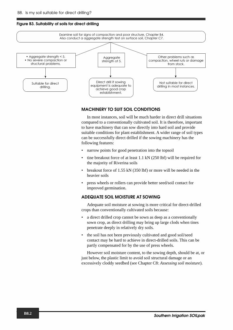
Figure B3 will help you decide whether your soil is suitable fordirect drilling. Examination of the topsoil condition is necessary (seeChapters C2 and C5).
B8. Is my soil suitable for direct drilling?
B8.2 Southern Irrigation SOILpak
äää
������������ ��������������������� �� ���� ��������� ������������������� ������� ������������� ��������������� ����
����� ������� ��������������� � �����������
� ���� ���� !����
"��� �� !�������������������#����� ��� �������
� ����$�
��� ������ ����������
%� ����� �������#����&�������������&������
����� ������ ����!��������
�������!���� ��� ���� ���������������������
'����!���� ��� ���� �������
Figure B3. Suitability of soils for direct drilling
MACHINERY TO SUIT SOIL CONDITIONS
In most instances, soil will be much harder in direct drill situationscompared to a conventionally cultivated soil. It is therefore, importantto have machinery that can sow directly into hard soil and providesuitable conditions for plant establishment. A wider range of soil typescan be successfully direct drilled if the sowing machinery has thefollowing features:
• narrow points for good penetration into the topsoil
• tine breakout force of at least 1.1 kN (250 lbf) will be required forthe majority of Riverina soils
• breakout force of 1.55 kN (350 lbf) or more will be needed in theheavier soils
• press wheels or rollers can provide better seed/soil contact forimproved germination.
ADEQUATE SOIL MOISTURE AT SOWING
Adequate soil moisture at sowing is more critical for direct-drilledcrops than conventionally cultivated soils because:
• a direct drilled crop cannot be sown as deep as a conventionallysown crop, as direct drilling may bring up large clods when tinespenetrate deeply in relatively dry soils.
• the soil has not been previously cultivated and good soil/seedcontact may be hard to achieve in direct-drilled soils. This can bepartly compensated for by the use of press wheels.
However soil moisture content, to the sowing depth, should be at, orjust below, the plastic limit to avoid soil structural damage or anexcessively cloddy seedbed (see Chapter C8: Assessing soil moisture).

B9. Is my soil suitable for raised bedfarming?
B9.1Southern Irrigation SOILpak
Chapter B9. Is my soilsuitable for raised bedfarming?SOIL REQUIREMENTS FOR BEDFARMING
A bedfarming system involves growing crops on raised beds that areirrigated via furrows. Furrows are generally spaced 1.5–2.0 m apart.Traffic is usually confined to furrows, thus confining soil compaction tospecific wheel rows/traffic lanes.
The major limitation of a soil for bedfarming is its ability to take upirrigation water from the furrow and allow water entry through theentire bed (known as subbing). A soil that subs readily is well suited tobedfarming.
There are number of factors that determine the suitability of a soilfor bedfarming. These include:
• soil group
• soil texture
• sodicity
• salinity
• watertable depth
• pH
SOIL GROUP, TEXTURE, AND SODICITY
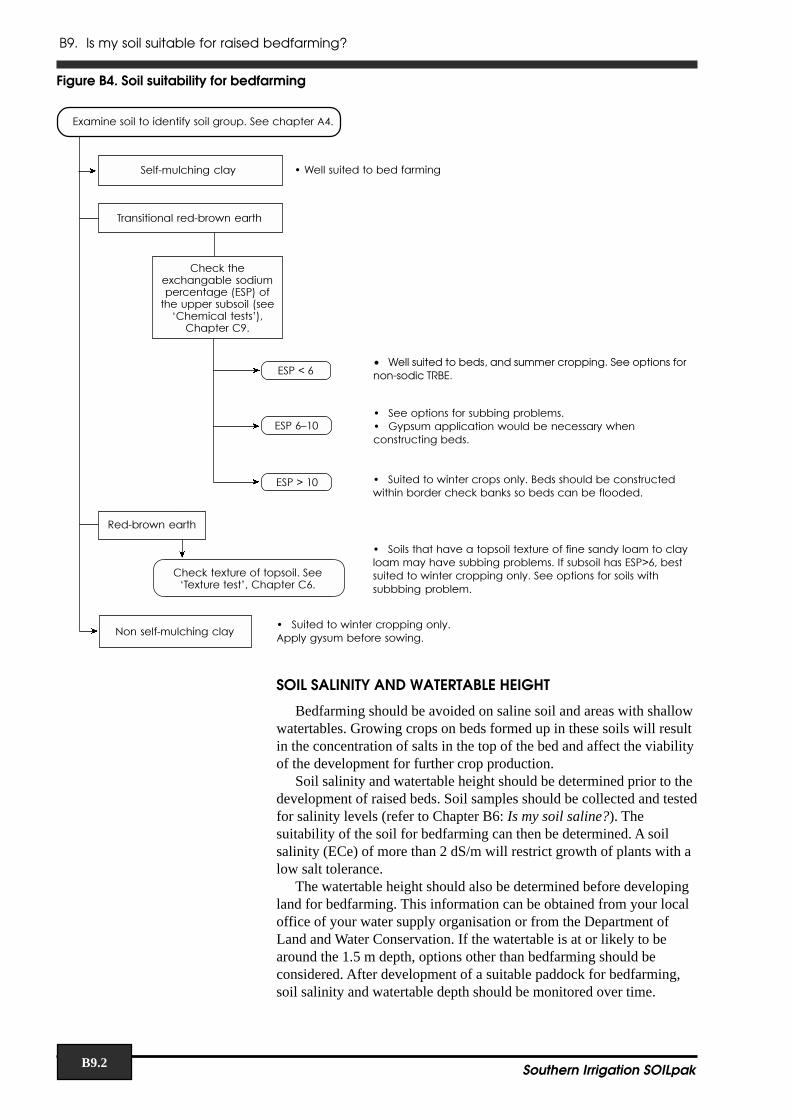
The following flowchart (Figure B4) will help you decide whetheryour soil is suitable for bedfarming, based on the soil group, textureand sodicity.
B9. Is my soil suitable for raised bedfarming?
B9.2 Southern Irrigation SOILpak
SOIL SALINITY AND WATERTABLE HEIGHT
Bedfarming should be avoided on saline soil and areas with shallowwatertables. Growing crops on beds formed up in these soils will resultin the concentration of salts in the top of the bed and affect the viabilityof the development for further crop production.
Soil salinity and watertable height should be determined prior to thedevelopment of raised beds. Soil samples should be collected and testedfor salinity levels (refer to Chapter B6: Is my soil saline?). Thesuitability of the soil for bedfarming can then be determined. A soilsalinity (ECe) of more than 2 dS/m will restrict growth of plants with alow salt tolerance.
The watertable height should also be determined before developingland for bedfarming. This information can be obtained from your localoffice of your water supply organisation or from the Department ofLand and Water Conservation. If the watertable is at or likely to bearound the 1.5 m depth, options other than bedfarming should beconsidered. After development of a suitable paddock for bedfarming,soil salinity and watertable depth should be monitored over time.
ä
�������������� ����������
��� ���������� ���������������������
������������������������������������� !��������������������"������������#!$
��������%&
�� '(
�� ()*+� ���������������������������&� ,��������������������������������������������������&
�� -*+ � ����������������������&.������������������������������������������������������������&
/�� ����������
����������������������������&����������01&
��������������������&���"�����������#$��������(&
� ����������2������������������������������������������2���������������&3������������ -($�����������������������������&�����������������������������������&
4����� ����������� �������������������������&0��������������������&
• Well suited to beds, and summer cropping. See options fornon-sodic TRBE.
Figure B4. Soil suitability for bedfarming
ä
ä
ä
ä
ä
B9. Is my soil suitable for raised bedfarming?
B9.3Southern Irrigation SOILpak
SOIL pH
Soil pH should also be checked before developing land forbedfarming. Most crops prefer a pH around neutral. Strongly acid soilsshould generally be avoided or treated. If the soil is strongly acid, limeshould be incorporated before bedding up for the initial crop.
OPTIONS FOR BEDFARMING SOILS WITH SUBBING PROBLEMS
Subbing problems generally arise in the loam topsoils of the red-brown earth (RBE) and transitional red-brown earth (TRBE) soils. Thisoccurs because the textures of these topsoils do not allow water to bereadily taken up by subbing.
RBEs and sodic TRBEs (subsoil ESP > 6)• Narrow beds:
• Form narrow beds (1.5–1.8 m wide) within border check bays• flood tops of beds as well as furrows at each irrigation• slightly shallower beds (around 10 cm high) and relatively flat
grades (flatter than 1:1200–1:1400) are required• flow rates should allow for fast watering.• grow only two rows of summer crop per bed• hills, with furrow spacings of 0.75–1.0m, are another good
option
• Permanent trickle irrigation (saturated soil culture)• method is suitable for production of soybeans only• maintains small amounts of water in the furrows at all times after
crop establishment• it is important to maintain water levels, as the soybean plant
quickly adapts to saturated conditions and becomes stressed ifthe soil is allowed to dry
Non-sodic TRBEs (subsoil ESP < 6)
• when landforming removes the loam topsoil from the paddock toexpose the subsoil
• the subsoil generally has better structure than the topsoil, and willstore more water after an irrigation when the topsoil is removed
• this soil type is evident in paddocks where cut areas yield better thanuncut or fill areas.
On all soil types, subbing problems may also develop whereshoulder compaction occurs due to the use of wheels on farmmachinery that are too wide.

B9. Is my soil suitable for raised bedfarming?
B9.4 Southern Irrigation SOILpak
B10. Managing paddocks with soil variation
B10.1Southern Irrigation SOILpak
Chapter B10. Managingpaddocks with soil variationINTRODUCTION
Irrigators are aware of variations in soil condition and cropperformance in at least some of their paddocks.
This chapter provides some general guidelines about themanagement of soil variations to minimise differences in cropperformance and yield. It also previews yield mapping technology,outlines how to sample the soil after studying a yield map, anddescribes how remote sensing data (eg. airborne thermal infra-redscanning) can assist.
SOURCES OF SOIL-RELATED VARIATION WITHINIRRIGATION PADDOCKS
Variations in crop performance within a paddock may be due to anyone, or a combination of factors. These include:
• insect and disease pressures
• passage of narrow, intense rain and hail storms
• changes in field slope
• presence of gilgais
• management variations (eg. contrasting periods of inundation byflood irrigation water between one end of a field and another),
• machinery malfunction (eg. uneven fertiliser or herbicideapplication)
• contrasting physical and chemical properties of soil.
Soil factors responsible for crop variations include:
• degree of compaction by farm machinery (due, for example, toheavy rain on a paddock part-way through a harvesting or landforming operation),
• soil stability in water, which is related to sodicity, electricalconductivity, pH, organic matter and clay mineral type
• soil texture, which influences infiltration rate, water-holdingcapacity and ability to shrink and swell
• depth of topsoil
• salinity
• pH
• nutrient reserves
PRODUCTION OF WITHIN-FIELD YIELD MAPS
The introduction of yield monitors on harvesters has allowedirrigators to easily identify poor yielding areas within paddocks. Soilsampling in the low and high yielding sections of a field will allow soilfactors causing yield differences to be identified. Precise soilmanagement programs to overcome crop yield variation can then bedesigned. Geographic Information Systems (GIS) enable yields and soil

B10. Managing paddocks with soil variation
B10.2 Southern Irrigation SOILpak
conditions to be mapped within the paddock. This will allow theirrigator to apply the appropriate inputs at various locations.
Where yield monitors are unavailable, crop yield variations can bemapped by hand-harvesting small sub-sections of paddocks. Anotherapproach is to map the average yield of large sub-sections of paddocksby noting the weight or the number of truck loads of grain.
Aerial photographs and airborne video scans of crops and bare soilcan help to show the location of problem areas. Even just a walkthrough a crop or pasture will provide a good indication of the best andworst performing sections of a field.
Because the effect of soil properties on crop growth usually isstrongly influenced by temperature and rainfall, yield monitoring needsto be repeated over several contrasting growing seasons.
INTERPRETING YIELD MAPS
Much can be learnt, even from the most basic of yield maps, byassessing soil condition at the best, worst and average points within apaddock. If the paddock contains obviously different soil units – eg. amosaic of red and grey soil – the best, average and worst yielding areaswithin each of these two soil groups should have their soil tested.
The soil description sheet for an existing irrigation developmentshould be filled out for each of these locations soon after harvest. Theresults should then be compared with the critical values presentedthroughout Section C.
If a strong relationship is evident between the measured soilproperties and grain/pasture yields, these soil properties should then bemapped. The soil factor maps produced form the basis of subsequentsoil management programs. For example, a soil stability map willindicate where gypsum should be applied to the soil and at what rates.
Yield maps are also useful for ensuring that access tubes for soilmoisture monitoring are located in representative positions within afield.
USE OF REMOTE SENSING DATA
Remote sensing data may help to greatly improve the accuracy ofthese soil factor maps. Where there is a strong relationship between keysoil factors and patterns seen in aerial photographs or videos, accuratemaps can be produced of that soil factor. For example salinity can bequite obvious on an aerial photo.

B11. Soil survey for irrigation development or redevelopment
B11.1Southern Irrigation SOILpak
Chapter B11. Soil survey forirrigation development orredevelopmentINTRODUCTION
When soil properties within a paddock are variable, it is usuallyimpossible to deliver irrigation water uniformly to all sections. As aconsequence, some parts of paddocks will receive more or less waterthan is optimal, with lower yields than is possible, and variations inproduct quality.
When planning a new irrigation development, each paddock shouldhave soil conditions and slope as uniform as possible. Consequently,the soil should be mapped before any irrigation design work is carriedout. In fields already developed for irrigation, soil variability may be sogreat that the paddock has to be redeveloped for irrigation to minimisethe variation within a paddock. Again, soil survey should occur prior toredesign. This is particularly important if a field is intended for ricegrowing.
In practice, it is unlikely to ever be economically feasible tocompletely remove across-field soil variability. However, if goodquality soil survey information is available, the variations within eachpaddock can be minimised in a cost-effective fashion.
SOIL SURVEY PRIOR TO NEW IRRIGATION DEVELOPMENT
Money spent on soil survey prior to development usually is repaidseveral times over because of the potential management problems thatit highlights. Soil survey information provides a benchmark that can beused to monitor changes in soil condition and fertility, in the chosencrop system, after irrigation development.
An electromagnetic survey (EM31 or EM38) can be used initially toidentify variations in factors related to the electrical conductivity of thesoil. The location of backhoe pits, in a grid pattern, can be based on theoutcome of an EM survey. The grid spacing will depend on the level ofvariation shown in the survey. More pits should be dug in an area ofhigh variation in EM readings than in areas of low variation. EM dataassists with site selection for backhoe pits or soil auger samples byidentifying areas of high and low soil conductivity, and helps to locatesoil property boundaries between the sites.
Landholders can assess their soils themselves for developmentpurposes by noting the following features in the topsoil (0–5 cm),subsurface (5–30 cm) and subsoil (30–100 cm):
• soil texture
• available water
• suitability of soil moisture for landforming
• aggregate stability in water
• natural regeneration potential
• salinity
• pH

B11. Soil survey for irrigation development or redevelopment
B11.2 Southern Irrigation SOILpak
These soil factors should be measured at several sites and mapped.Geographic Information Systems (GISs) are available to map soilproperties on home computers – they allow the different layers of soilinformation for a field to be stored in an orderly fashion. This allowsthe variation in each soil property and combinations of properties to beobserved. The maps also allow soil with similar, difficult-to-modify,properties (e.g. water holding capacity, shrink/swell potential) to beincluded within the same management units.
After design of the irrigation layout:• landform each of the new irrigation paddocks (when dry if
possible); try to avoid deep cuts into sodic subsoil• create check banks, contour banks or raised beds, depending on
chosen irrigation layout• refer to the next chapter for suggestions about how to treat the soil
after landforming
SOIL SURVEY PRIOR TO REDEVELOPMENT OF IRRIGATIONPADDOCKS
Irrigated paddocks are redeveloped for a number of reasons.These include:• subsided areas with poor surface drainage• impractical paddock size or shape• impractical mosaic of contrasting soil types• improved irrigating and drainage• incorporating drainage and reuse systems• different land uses (eg. crop type)
Redevelopment provides an opportunity to properly assess, and ifpossible correct, soil problems that have been reducing farmprofitability. It also allows soil with similar, difficult-to-modify,properties (e.g. water holding capacity) to be included within the samemanagement units.
The procedures described above for development of new irrigationpaddocks should be followed when redeveloping. The best grid spacingto use is uncertain. A spacing of 75 m is recommended, as a firstapproximation, for land that obviously contains soil variation (e.g.a mosaic of red and grey soil). For land with less obvious variation, aspacing of 150 m is suggested. Soil variation mapped by an EM surveycan be used as a guide for the location and grid spacing of backhoe pitsand auger sampling sites.
You can assess your soil for new irrigation development orredevelopment by noting the following features in the topsoil (0–5 cm),subsurface (5–30 cm) and subsoil (30–100 cm):
• soil texture
• available water
• suitability of soil moisture for landforming
• aggregate stability in water
• natural regeneration potential
• salinity
• pH
These soil factors can be mapped using a GIS as previously mentioned.
After design of the irrigation layout follow the same guidelines asfor development of a new irrigation layout.

B12. Managing recently landformed areas
B12.1Southern Irrigation SOILpak
Chapter B12. Managingrecently landformed areasINTRODUCTION
Landforming is necessary to improve irrigation applicationefficiency and surface drainage. However landforming can have thefollowing detrimental effects on soil condition:
• exposure of unfavourable subsoil
• structural damage
These problems should be dealt with before growing a crop afterlandforming.
SOIL MANAGEMENT PROBLEMS THAT MAY OCCUR DURINGAND AFTER LANDFORMING
Exposure of unstable subsoil
Subsoil exposure is usually unavoidable because of the need toprovide an even slope in irrigated fields. The subsoil may be low innutrients and organic matter. Worse still, it may be sodic, and thereforedispersive, have a high pH and perhaps be saline. The subsoil generallyhas a higher density than the topsoil, which offers higher resistance toroot growth and may cause slower infiltration and internal drainage.
Structural Damage
CompactionTo avoid compaction of clay soil during landforming, the soil profile
should be dried as much as possible prior to landforming. This can beachieved by growing a well fertilised crop such as wheat. The chanceof the soil being drier than the plastic limit at landforming ismaximised, and the risk of soil compaction is minimised.
However, due to the tight schedules of landforming contractors, it isdifficult to reshape fields at exactly the correct soil water content. If thesoil is wetter than the plastic limit there is a risk of compactionoccurring. Compaction provides unfavourable conditions for plantgrowth. This occurs through a reduction in porosity and available watercontent, and an increase in soil density which reduces drainage andenhances waterlogging.
PulverisationOn loam soil, landforming under dry conditions may create
excessive amounts of dust. When re-wetted, this pulverised soil tendsto set hard and become very dense.
However, if there is heavy rain before landforming and thecontractors cannot be delayed, deep compaction may occur. The extentof compaction must be identified after landforming, and methods torepair the compaction considered. (see Chapter B4: Do I have acompaction problem?).

B12. Managing recently landformed areas
B12.2 Southern Irrigation SOILpak
TECHNIQUES FOR OBTAINING MAXIMUM PRODUCTIONFROM LANDFORMED AREAS
Topsoiling cut areas
Where subsoil has unfavourable characteristics, it is desirable tostockpile topsoil during landforming. The subsoil is then landformedand the topsoil replaced. Research has shown that topsoiling is thequickest, and most effective way of returning cut areas to maximumproduction, and is therefore highly recommended. A subsoil exposed ina heavily cut area should receive at least 10 cm of topsoil for bestresults.
It should be noted that some non-sodic transitional red-brown earthshave a subsoil that has superior physical characteristics relative to itstopsoil. In these soils topsoiling should not be carried out. The topsoil isbest removed from the paddock and used for other purposes.
Gypsum application to cut areas
If topsoiling is not possible, exposed sodic subsoil will have to bereclaimed by applying gypsum. To determine the appropriate gypsumapplication rate, sodicity (ESP) needs to be measured by a laboratorytest. Where ESP >6 the soil is sodic and will respond to gypsumapplication. Figure B5 indicates the gypsum application rate to preventdispersion in sodic soils.
ä ä
������������������ ������������������������������������� ���������������� ������ �
!���"�#$%��& ���"����
����'�()����*$()
Figure B5. Gypsum application rates for cut areas
!���"�%��& ���"����
Note that gypsum should not be applied within 18 months beforesowing a rice crop.
N, P and Zn application to cut areas
Where subsoil has been exposed the levels of some nutrients arelikely to be low. Application of deficient nutrients, will improve yieldsof crops and pastures grown on landformed paddocks.
NitrogenYield responses in winter cereals sown in cut areas are likely when
nitrogen is applied at 100 kg N/ha. Between 20–50 kg N/ha should bedrilled prior to sowing. The remaining N can be applied at about eightweeks after sowing if establishment is good.
PhosphorusSoil P levels are determined at commercial testing laboratories using
the Colwell test. Figure B6 shows the recommended rate of Papplication in cut areas.

B12. Managing recently landformed areas
B12.3Southern Irrigation SOILpak
ZincZinc should be applied to all cut areas (where topsoiling has not
been carried out). Application rate is dependent on soil pH in some soiltypes. Figure B7 will enable you to determine the appropriate Znapplication rate for your soil.
ä
ä ä
Figure B7. Zinc application rates for cut areas
+�"����,���� �������" -� ��
!���"�()�.��/�& ��
�0�1�2 �0�'�2
3���.��"��������������4����5����
!���"�()�.�& ����/��
� ��.�������0�������
������ ��������������� ������ �
6 ������� ��������"��7�� �����!8�
ää
��������������������
1�()���� '�(%����
!���"�8)�.���& �
Figure B6. Phosphorus application rates for cut areas
!���"�#)�.���& �

B12. Managing recently landformed areas
B12.4 Southern Irrigation SOILpak