software validation test report for lithotecttm, version 1
TRANSCRIPT

SOFTWARE VALIDATION TEST REPORT FOR LITHOTECTTM, VERSION 1.20
Prepared for
U.S. Nuclear Regulatory Commission Contract NRC-02-02-012
Prepared by
Paul S. Landis Kevin J. Smart
Center for Nuclear Waste Regulatory Analyses San Antonio, Texas
November 2004
Approved by:
///z /sy ' [Date
Manager, Geology & Geophysics

i
TABLE OF CONTENTS
FIGURES . . . . . . . . . . . . . . . . . . . . . . . . . . . . . . . . . . . . . . . . . . . . . . . . . . . . . . . . . . . ii
1 SCOPE OF THE VALIDATION . . . . . . . . . . . . . . . . . . . . . . . . . . . . . . . . . . . . . . . . . 1
2 ENVIRONMENT . . . . . . . . . . . . . . . . . . . . . . . . . . . . . . . . . . . . . . . . . . . . . . . . . . . . 12.1 Software and Operating System Requirements . . . . . . . . . . . . . . . . . . . . . . 12.2 Hardware Requirements . . . . . . . . . . . . . . . . . . . . . . . . . . . . . . . . . . . . . . . . 12.3 Test Machine Specifications . . . . . . . . . . . . . . . . . . . . . . . . . . . . . . . . . . . . . 2
3 PREREQUISITES . . . . . . . . . . . . . . . . . . . . . . . . . . . . . . . . . . . . . . . . . . . . . . . . . . . 2
4 ASSUMPTIONS AND CONSTRAINTS . . . . . . . . . . . . . . . . . . . . . . . . . . . . . . . . . . 2
5 TEST CASES . . . . . . . . . . . . . . . . . . . . . . . . . . . . . . . . . . . . . . . . . . . . . . . . . . . . . . 25.1 Test Case 1 – Verification of Project Management Tools . . . . . . . . . . . . . . . 2
5.1.1 Test Input . . . . . . . . . . . . . . . . . . . . . . . . . . . . . . . . . . . . . . . . . . . . . 35.1.2 Test Procedure . . . . . . . . . . . . . . . . . . . . . . . . . . . . . . . . . . . . . . . . 35.1.3 Test Results . . . . . . . . . . . . . . . . . . . . . . . . . . . . . . . . . . . . . . . . . . . 3
5.2 Test Case 2 – Verification of Flexural Slip Restoration Functionality . . . . . . . 35.2.1 Test Input . . . . . . . . . . . . . . . . . . . . . . . . . . . . . . . . . . . . . . . . . . . . . 35.2.2 Test Procedure . . . . . . . . . . . . . . . . . . . . . . . . . . . . . . . . . . . . . . . . 45.2.3 Test Results . . . . . . . . . . . . . . . . . . . . . . . . . . . . . . . . . . . . . . . . . . . 4
5.3 Test Case 3 – Verification of Forward Modeling Functionality . . . . . . . . . . . . 45.3.1 Test Input . . . . . . . . . . . . . . . . . . . . . . . . . . . . . . . . . . . . . . . . . . . . . 45.3.2 Test Procedure . . . . . . . . . . . . . . . . . . . . . . . . . . . . . . . . . . . . . . . . 45.3.3 Test Results . . . . . . . . . . . . . . . . . . . . . . . . . . . . . . . . . . . . . . . . . . . 5
5.4 Test Case 4 – Verification of Vertical/Oblique Slip Restoration Functionality 55.4.1 Test Input . . . . . . . . . . . . . . . . . . . . . . . . . . . . . . . . . . . . . . . . . . . . . 55.4.2 Test Procedure . . . . . . . . . . . . . . . . . . . . . . . . . . . . . . . . . . . . . . . . 55.4.3 Test Results . . . . . . . . . . . . . . . . . . . . . . . . . . . . . . . . . . . . . . . . . . . 5
6 SUMMARY . . . . . . . . . . . . . . . . . . . . . . . . . . . . . . . . . . . . . . . . . . . . . . . . . . . . . . . . 6
7 REFERENCES . . . . . . . . . . . . . . . . . . . . . . . . . . . . . . . . . . . . . . . . . . . . . . . . . . . . . 6
ii
FIGURES
Figure Page
1 Published map (A) (Rowland and Duebendorfer, 1994) used as the input file for test case 1 . . . . . . . . . . . . . . . . . . . . . . . . . . . . . . . . . . . . . . . . . . . . . . . . . . . 7
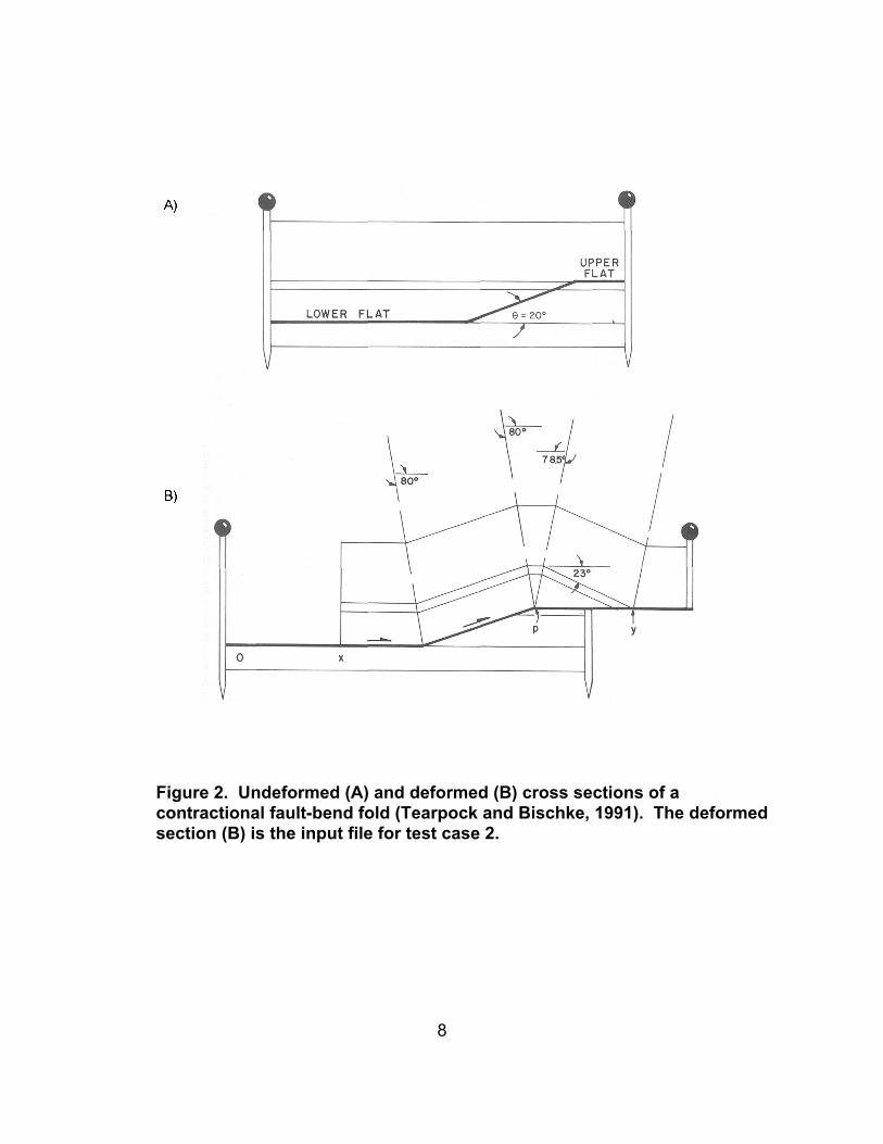
2 Undeformed (A) and deformed (B) cross sections of a contractional fault-bend fold(Tearpock and Bischke, 1991). . . . . . . . . . . . . . . . . . . . . . . . . . . . . . . . . . . . . . . . . . . . . . 8
3 Digitized fault-bend fold showing (A) deformed horizons, (B) parameters used to restorethe section . . . . . . . . . . . . . . . . . . . . . . . . . . . . . . . . . . . . . . . . . . . . . . . . . . . . . . . . . . . . . 9
4 (A) Undeformed extensional cross section displaying parameters used to displace hangingwall block for test case 3. . . . . . . . . . . . . . . . . . . . . . . . . . . . . . . . . . . . . . . . . . . . . . . . . 10

1
1 SCOPE OF VALIDATION
This report documents the Software Validation Test results for the limited validation ofthe functionality of LithoTect™, version 1.20. LithoTect™ was acquired by the Centerfor Nuclear Waste Regulatory Analyses (CNWRA) of Southwest Research Institute®
(SwRI) to provide additional technical assistance capabilities to the Nuclear RegulatoryCommission (NRC) in their high-level nuclear waste geologic repository program.
These test results are intended to validate LithoTect™ program features that are usedto create and display geologic data in map, cross section, and stratigraphic sectionviews in addition to validate the cross section restoration and forward modelingcapabilities. Specific features that will be validated include: (i) construction of mapsfrom imported images, (ii) flexural slip kinematic restoration, (iii) interactive deformationof an undeformed cross section using the forward modeling algorithm, and(iv) vertical/oblique slip kinematic restoration. The tests described herein are based onthe partial Software Validation Test Plan (SVTP) for the limited validation of LithoTect™,version 1.20 (Landis and Smart, 2004).
2 ENVIRONMENT
2.1 Software and Operation System Requirements
LithoTect™ is developed and marketed by Geo-logic Systems, located in Boulder,Colorado. LithoTect™ runs on Microsoft® Windows 95/98/2000/NT/4.0/ME/XPoperating systems and Solaris and Linux platforms. LithoTect™ is a pure Javaapplication requiring Java 2 Runtime Environment Version 1.3.0_02 or later to operatecorrectly.
Data can be imported in a variety of formats depending on the type of data required. Images can be imported as, but are not limited to, .TIF, .JPG, or .GIF file formats. Datafiles consisting of line data or point data can be imported as ASCII comma delimited textfiles or input directly by the user.
2.2 Hardware Requirements
LithoTect™ requires an IBM-PC compatible computer or UNIX workstation with a256 MHz or faster processor and at least 256 MB of RAM. The recommendedconfiguration is a 1 GHz or faster processor and at least 512 MB of RAM. LithoTect™can print output to any installed printer and to CGM files that can be imported intoAdobe® Illustrator®.

2
2.3 Test Machine Specifications
The validation tests were performed on a 6 x 1.2 GHz Sun Fire V880Z workstation. This machine is equipped with 24 GB of RAM, multiple hard drives and the SunOS 5.9operating system.
3 PREREQUISITES
Prerequisites for successful installation and execution of LithoTect™ include thecompatible operating systems defined in Section 2.1 and hardware specificationsexceeding those detailed in Section 2.2. Installation of the program and license filesrequires administrator privileges. However, administrator privileges are not required toexecute the program once installation is complete.
4 ASSUMPTIONS AND CONSTRAINTS
The user of LithoTect™ is assumed to have a basic understanding of structural geology,including cross section construction, and fold and fault kinematics. The programinstallation provides a HTML-format help page that contains an index of help files thatexplain most functions of LithoTect™. However, the help system is under constructionand does not detail some advanced functions. In addition, a tutorial project is providedthat describes the basic features of the program.
5 TEST CASES
This validation test results report follows CNWRA requirements as outlined inSection 5.10 of TOP–018 (CNWRA, 2003) and utilizes the test cases outlined in theLithoTect™ (version 1.20) SVTP (Landis and Smart, 2004). The success of the testcases is based on comparisons to published data and to files generated by LithoTect™in other test cases. Specifically, files used and generated in test case 3 are comparedto files in test case 4. The test cases are considered successful if functions withinLithoTect™ produce results that are visually identical to published data or toLithoTect™ files.
5.1 Test Case 1 – Verification of Project Management Tools
The ability to create maps, stratigraphic columns, and outcrop orientation data is crucialto the development of structural projects. Without properly constructed project data,structural interpretation would be severely limited. This test evaluates the projectcreation capabilities including importing images, digitizing images, importing outcroporientation data, and generating stratigraphic columns.

3
5.1.1 Test Input
The test input for this case consists of a published geologic map that contains outcroporientation data (Rowland and Duebendorfer, 1994). The published map is provided inFigure 1A.
5.1.2 Test Procedure
A project was created by specifying the “New Project” option in LithoTect™. Initially, astratigraphic column consisting of the map units, gabbro, and Formation M was createdusing the “new column” option (Figure 1B). The published map (Figure 1A) wasimported as a .JPG image and was recreated using the digitizing tools in the map viewwindow. Because the type of boundary between Formation M and gabbro is notspecified by Rowland and Duebendorfer (1994), the boundary was digitized as a fault totest the creation of different line types. Units created in the stratigraphic column(Figure 1B) were then transferred to the regions digitized on the map. Finally, the strikeand dip data present in Figure 1A was imported as sample/outcrop data from a comma-delimited ASCII text file.
5.1.3 Test Results
The digitized map created with LithoTect™ (Figure 1C) is identical to the publishedsource (Figure 1A) (Rowland and Duebendorfer, 1994). As a result, test case 1 isconsidered successful.
5.2 Test Case 2 – Verification of Flexural Slip Restoration Functionality
Restoration of cross sections is used to evaluate cross section validity andinterpretation. Properly constructed cross sections restore to an original state that isgeologically valid. LithoTect™ allows the user to select from two different kinematic slipmodels, flexural slip, and vertical/oblique slip, to restore geologic cross sections. Theflexural restoration option restores deformed sections through curvilinear vectors andassumes a parallel geometry in which layer thickness remains constant. Thevertical/oblique slip kinematic model restores cross sections through straight-linevectors (either vertical or inclined at a user-specified angle) and assumessimilar geometry.
5.2.1 Test Input
The test input for this case consists of a published cross section of a contractional fault-bend fold (Tearpock and Bischke, 1991). The undeformed fault-bend fold and thedeformed cross section are provided in Figures 2A and 2B, respectively.

4
5.2.2 Test Procedure
The fault-bend fold (Figure 2B) was imported into a new project as a .JPG image withthe “Import” –> “Image” option. There, the unit tops and fault were digitized in the depthprofile view (Figure 3A). The fold was restored by selecting the “Restoration” tab and byusing the “Interactive” –> “Flexural” –> “Regions” options. The hanging wall of the fault-bend fold was the block that underwent flexural restoration, and the restoration wasperformed on reference lines that extend from the footwall (Figure 3B). Theconfiguration of the reference lines restored the hanging wall directly adjacent to thefootwall (Figures 3A and 3B).
5.2.3 Test Results
The restored contractional fault-bend fold is provided in Figure 3C. The publishedundeformed section (Figure 2A) (Tearpock and Bischke, 1991) and the undeformedsection created with LithoTect™ (Figure 3C) are nearly identical. Because the fault-bend fold was digitized from a scanned image, it was difficult to maintain unit thicknessacross the fault. Therefore, the undeformed cross section created with LithoTect™contains areas in which stratigraphic horizons are not perfectly straight lines. This is aproduct of the scanning and digitizing process and does not reflect inaccuracies with theflexural restoration algorithm. Based on the comparison between the published sectionand the restored section generated with LithoTect™, test case 2 isconsidered successful.
5.3 Test Case 3 – Verification of Forward Modeling Functionality
Structural forward modeling is a technique used to deform an undeformed cross sectionto evaluate the stratigraphic response. LithoTect™ uses an interactive forwardmodeling algorithm that allows the user to quickly deform a section by selecting the faultto slip on, the angle of slip, the units undergoing deformation, and the amount ofdisplacement. This technique enables the user to visualize deformation processes andaids in the construction of geologically valid cross sections.
5.3.1 Test Input
The test input for this case consists of an extensional geologic cross section and itscorresponding restored section that was based on cross sections fromGroshong (1999).
5.3.2 Test Procedure
The published extensional cross sections (Groshong, 1999) served as templates thatwere used to create a simplified extensional cross section consisting of a single hangingwall and footwall block (Figure 4A). The undeformed cross section (Figure 4A) wasgenerated in the depth profile view. The hanging wall was deformed by selecting the
5
“Forward Modeling” tab and specifying the “Vertical/Oblique” –> “Lines” option. Figure 4A outlines the parameters used to deform the hanging wall. The cross sectionwas deformed using 90° (pure vertical) slip.
5.3.3 Test Results
The deformed cross section generated using the forward modeling algorithm is providedin Figure 4B. Overall success of this test case is dependent on the output of testcase 4. In test case 4, the output from test case 3 (Figure 4B) will be restored using thevertical/oblique slip algorithm. Because the undeformed section was deformed using90° vertical/oblique slip, the restoration algorithm will restore the cross section to anundeformed state that is visually identical to the original digitized section (Figure 4A). Ifthe files are visually identical, then test case 3 and test case 4 will beconsidered successful.
5.4 Test Case 4 – Verification of Vertical/Oblique Slip Restoration Functionality
In addition to flexural slip restoration, LithoTect™ provides a vertical/oblique sliprestoration option for validating cross sections. While flexural slip restoration is used forcontractional sections, vertical/oblique restoration is primarily used for extensional crosssections. Vertical/oblique kinematic slip restores cross sections along straight-linevectors, either vertical or inclined at a user-specified angle.
5.4.1 Test Input
The test input for this case will be the output from test case 3 (Figure 4B).
5.4.2 Test Procedure
The output from test case 3 was restored by selecting the “Restoration” tab andselecting the “Interactive” –> “Vertical/Oblique Slip” –> “Lines” options. The deformedcross section was restored using 90° (pure vertical) slip. The deformed horizon was theportion of the hanging wall directly adjacent to the fault and was restored along theentire length of the fault. Figures 4C and 4D outline the parameters used to restore thecross section.
5.4.3 Test Results
The undeformed extensional cross section (Figure 4D) generated by LithoTect™ for thistest case was compared to the input file for test case 3 (Figure 4A). Although differentalgorithms were used to deform and restore the extensional cross section, theundeformed output from the restoration (Figure 4D) is visually identical to the digitizedcross section (Figure 4A) used in the forward modeling algorithm. Based on thiscomparison, test case 3 and test case 4 are considered successful.
6
6 SUMMARY
All test cases were successfully completed. Therefore, it is concluded that the programfeatures tested in LithoTect™, version 1.20 are validated.
7 REFERENCES
CNWRA. “Development and Control of Scientific and Engineering Software.” TechnicalOperating Procedure TOP-018 (revision 8, change 2). Center for Nuclear WasteRegulatory Analyses (CNWRA). San Antonio, Texas. Effective date – July 03, 2003.
Groshong, R.H. 3-D Structural Geology: A Practical Guide to Surface and SubsurfaceMap Interpretation. Berlin. Springer-Verlag. 324 pp. 1999.
Landis, P.S. and K.J. Smart. “Software Validation Test Plan for LithoTect™, Version1.20. CNWRA. San Antonio, Texas. 2004.
Rowland, S.M. and E.M. Duebendorfer. Structural Analysis and Synthesis: ALaboratory Course in Structural Geology. Boston. Blackwell Scientific Publications. 279 pp. 1994.
Tearpock, D.J. and R.E. Bischke. Applied Subsurface Geological Mapping. UpperSaddle River. Prentice-Hall PTR. 648 pp. 1991.

7
Figure 1. Published map (A) (Rowland and Duebendorfer, 1994) used asthe input file for test case 1, and (B) stratigraphic column used to defineunits, and (C) digitized map generated with LithoTect™.
8
Figure 2. Undeformed (A) and deformed (B) cross sections of acontractional fault-bend fold (Tearpock and Bischke, 1991). The deformedsection (B) is the input file for test case 2.

9
Figure 3. Digitized fault-bend fold showing (A) deformed horizons,(B) parameters used to restore the section, and (C) output generated withLithoTect™ using the flexural slip kinematic algorithm.

10
Figure 4. (A) Undeformed extensional cross section displaying parameters used to displace hanging wall blockfor test case 3. (B) Deformed section generated using the forward modeling algorithm. (C) Deformed crosssection (B) used as input for test case 4. (D) Restored cross section using the vertical/oblique kinematic sliprestoration feature. Parameters used to restore the cross section are noted in 4C and 4D.