software for electrical and photovoltaic engineering · software for electrical and photovoltaic...
TRANSCRIPT
Electro Graphics Srl - 049.9461138 - www.electrographics.it - [email protected]
Software for electrical and photovoltaic engineering
The Electro Graphics software for electrical and photo-voltaic design, creates an environment with flexiblesolutions and integrated resources, in order to respondto the real needs day by day. Wiring diagrams, bill ofmaterials, calculation reports, plant layouts and budgetand accounting documents communicate with eachother to offer the tranquility of a safe and reliabledesign. The best use of desktop and mobile tools,make diagrams and design data accessible in the sim-plest way, where they needs.
Compatibility with AutoCAD
The software CADelet are now compatible with Auto-CAD version 2007 to 2018, 32 or 64 bit.
iDEA Eplus are based on AutoCAD® OEM 2018 a 64 bit
One of the most important innovations on the ElectroGraphics products is the transition from the 2013 ver-sion to the 2018 version of the Autodesk AutoCAD®OEM engine inside iDEA and EPLUS.Below we put the focus only on the most significant fea-tures introduced in Autodesk AutoCAD® OEM 201864-bit.• Interface display with dark themeThe new dark interface, not only looks attractive, butalso reduces eye strain. Thin lines, buttons and text aremore evident. You can switch from dark to traditionallight, setting one of the general options in the CAD.
iDEA with dark theme
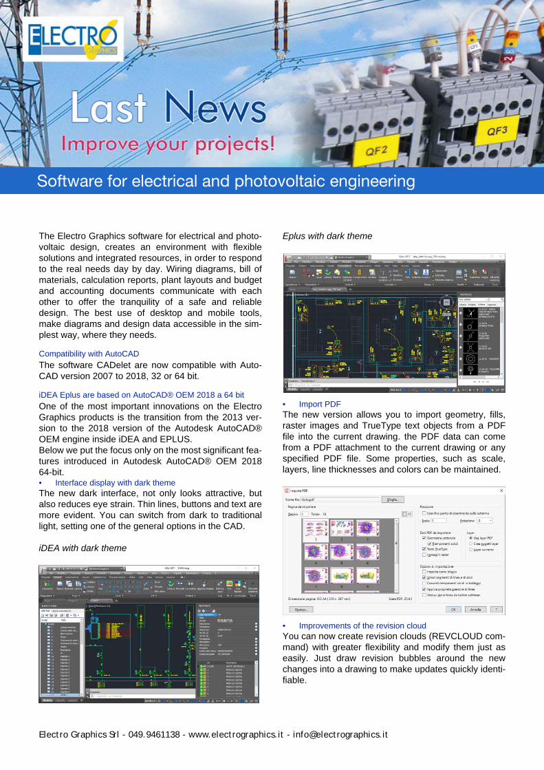
Eplus with dark theme
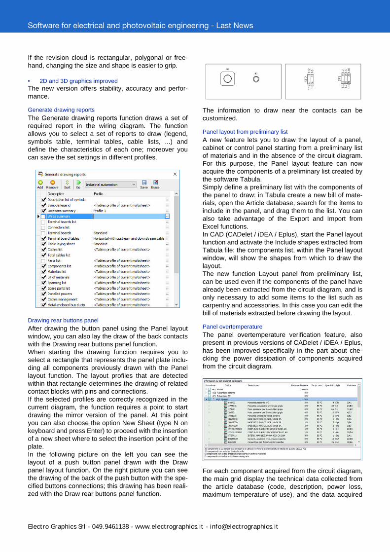
• Import PDFThe new version allows you to import geometry, fills,raster images and TrueType text objects from a PDFfile into the current drawing. the PDF data can comefrom a PDF attachment to the current drawing or anyspecified PDF file. Some properties, such as scale,layers, line thicknesses and colors can be maintained.
• Improvements of the revision cloudYou can now create revision clouds (REVCLOUD com-mand) with greater flexibility and modify them just aseasily. Just draw revision bubbles around the newchanges into a drawing to make updates quickly identi-fiable.
Software for electrical and photovoltaic engineering - Last News
Electro Graphics Srl - 049.9461138 - www.electrographics.it - [email protected]
If the revision cloud is rectangular, polygonal or free-hand, changing the size and shape is easier to grip.
• 2D and 3D graphics improvedThe new version offers stability, accuracy and perfor-mance.
Generate drawing reports
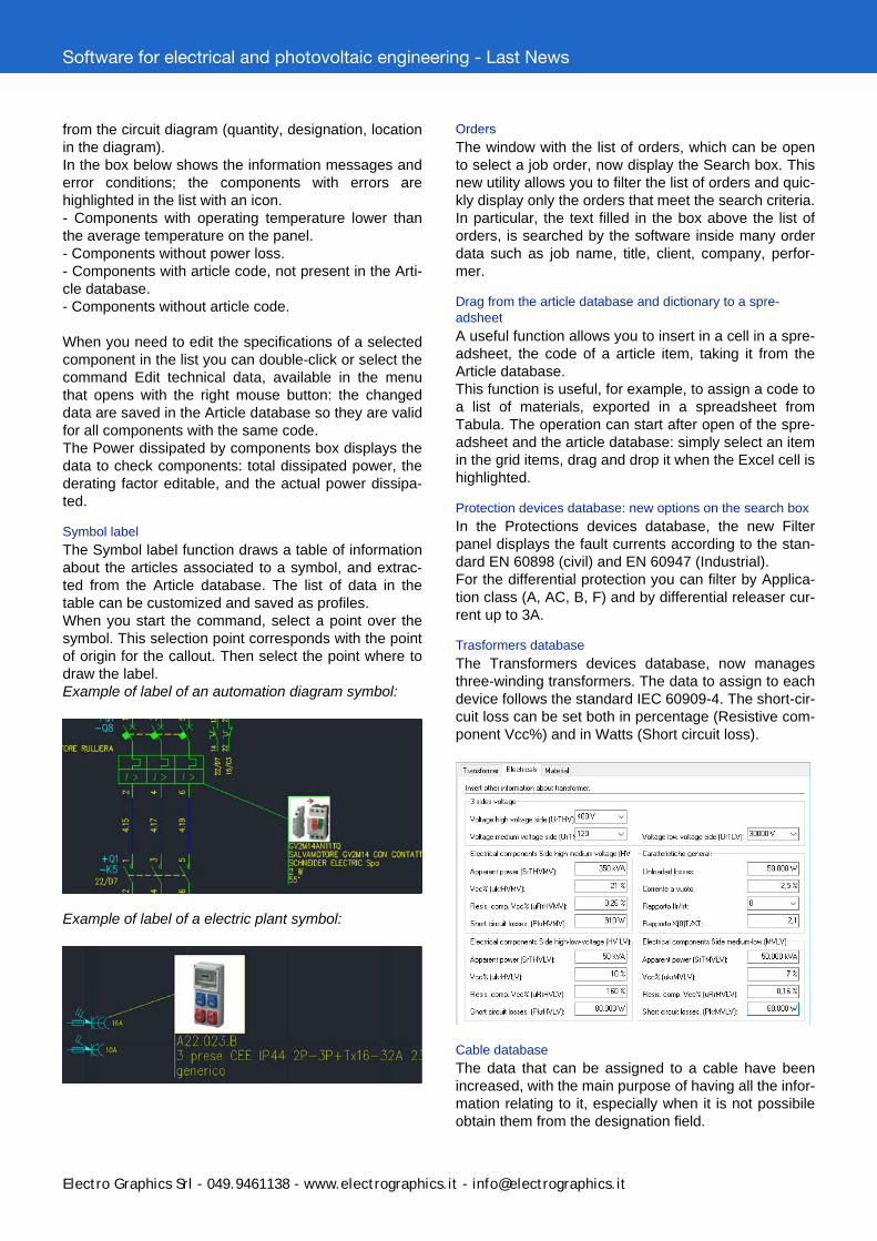
The Generate drawing reports function draws a set ofrequired report in the wiring diagram. The functionallows you to select a set of reports to draw (legend,symbols table, terminal tables, cable lists, ...) anddefine the characteristics of each one; moreover youcan save the set settings in different profiles.
Drawing rear buttons panel
After drawing the button panel using the Panel layoutwindow, you can also lay the draw of the back contactswith the Drawing rear buttons panel function.When starting the drawing function requires you toselect a rectangle that represents the panel plate inclu-ding all components previously drawn with the Panellayout function. The layout profiles that are detectedwithin that rectangle determines the drawing of relatedcontact blocks with pins and connections.If the selected profiles are correctly recognized in thecurrent diagram, the function requires a point to startdrawing the mirror version of the panel. At this pointyou can also choose the option New Sheet (type N onkeyboard and press Enter) to proceed with the insertionof a new sheet where to select the insertion point of theplate.In the following picture on the left you can see thelayout of a push button panel drawn with the Drawpanel layout function. On the right picture you can seethe drawing of the back of the push button with the spe-cified buttons connections; this drawing has been reali-zed with the Draw rear buttons panel function.
The information to draw near the contacts can becustomized.
Panel layout from preliminary list
A new feature lets you to draw the layout of a panel,cabinet or control panel starting from a preliminary listof materials and in the absence of the circuit diagram.For this purpose, the Panel layout feature can nowacquire the components of a preliminary list created bythe software Tabula.Simply define a preliminary list with the components ofthe panel to draw: in Tabula create a new bill of mate-rials, open the Article database, search for the items toinclude in the panel, and drag them to the list. You canalso take advantage of the Export and Import fromExcel functions.In CAD (CADelet / iDEA / Eplus), start the Panel layoutfunction and activate the Include shapes extracted fromTabula file: the components list, within the Panel layoutwindow, will show the shapes from which to draw thelayout.The new function Layout panel from preliminary list,can be used even if the components of the panel havealready been extracted from the circuit diagram, and isonly necessary to add some items to the list such ascarpentry and accessories. In this case you can edit thebill of materials extracted before drawing the layout.
Panel overtemperature
The panel overtemperature verification feature, alsopresent in previous versions of CADelet / iDEA / Eplus,has been improved specifically in the part about che-cking the power dissipation of components acquiredfrom the circuit diagram.
For each component acquired from the circuit diagram,the main grid display the technical data collected fromthe article database (code, description, power loss,maximum temperature of use), and the data acquired
Software for electrical and photovoltaic engineering - Last News
Electro Graphics Srl - 049.9461138 - www.electrographics.it - [email protected]
from the circuit diagram (quantity, designation, locationin the diagram).In the box below shows the information messages anderror conditions; the components with errors arehighlighted in the list with an icon.- Components with operating temperature lower thanthe average temperature on the panel.- Components without power loss.- Components with article code, not present in the Arti-cle database.- Components without article code.
When you need to edit the specifications of a selectedcomponent in the list you can double-click or select thecommand Edit technical data, available in the menuthat opens with the right mouse button: the changeddata are saved in the Article database so they are validfor all components with the same code.The Power dissipated by components box displays thedata to check components: total dissipated power, thederating factor editable, and the actual power dissipa-ted.
Symbol label
The Symbol label function draws a table of informationabout the articles associated to a symbol, and extrac-ted from the Article database. The list of data in thetable can be customized and saved as profiles.When you start the command, select a point over thesymbol. This selection point corresponds with the pointof origin for the callout. Then select the point where todraw the label.Example of label of an automation diagram symbol:
Example of label of a electric plant symbol:
Orders
The window with the list of orders, which can be opento select a job order, now display the Search box. Thisnew utility allows you to filter the list of orders and quic-kly display only the orders that meet the search criteria.In particular, the text filled in the box above the list oforders, is searched by the software inside many orderdata such as job name, title, client, company, perfor-mer.
Drag from the article database and dictionary to a spre-adsheet
A useful function allows you to insert in a cell in a spre-adsheet, the code of a article item, taking it from theArticle database.This function is useful, for example, to assign a code toa list of materials, exported in a spreadsheet fromTabula. The operation can start after open of the spre-adsheet and the article database: simply select an itemin the grid items, drag and drop it when the Excel cell ishighlighted.
Protection devices database: new options on the search box
In the Protections devices database, the new Filterpanel displays the fault currents according to the stan-dard EN 60898 (civil) and EN 60947 (Industrial).For the differential protection you can filter by Applica-tion class (A, AC, B, F) and by differential releaser cur-rent up to 3A.
Trasformers database
The Transformers devices database, now managesthree-winding transformers. The data to assign to eachdevice follows the standard IEC 60909-4. The short-cir-cuit loss can be set both in percentage (Resistive com-ponent Vcc%) and in Watts (Short circuit loss).
Cable database
The data that can be assigned to a cable have beenincreased, with the main purpose of having all the infor-mation relating to it, especially when it is not possibileobtain them from the designation field.
Software for electrical and photovoltaic engineering - Last News
Electro Graphics Srl - 049.9461138 - www.electrographics.it - [email protected]
In the Properties dialog of a cable, the following fieldshave been added:• insulation;• sheath;• armor;• Maximum temperature cable (operating temperatureat rated current);• reference temperature for installation in the air andinground;• resistivity and depth in the ground to put ingroundlaying;• last modified date, out of production, year of produc-tion;• favorite; type of insulation, maximum cable sheathand armor temperature.
Now the archive is complete to be able to provide allthe features of a cable when a manufacturer assigns a'special designation', that is commercial rather thantechnical. The insulation type XLPE (Cross-linked pol-yethylene) is now managed. It is fully applicable withthe laying IEC 60502-2, which has specific load chartsfor this insulator. Now you can enter detailed specifica-tions of some manufacturers, which provide the refe-rence temperature of the flow for installation in the airand inground. For, the inground laying, you can nowspecify up to two pairs flow / ground resistivity.
INDUSTRIAL AUTOMATION
Diagram analysis• Automatic update of wire numberingThe automatic update of wire numbering is an opera-tion of the CAD, that in response to some changes tothe wiring diagram, updates the numbering of the wiresin the current sheet. This operation is equivalent to exe-cute the diagram analysis with the Current sheet optionselected.It is executed in response to drawing opera-tions or modification of wires, and the insertion ofsymbols on the wires.At any time you can turn it off and turn it on.
• Automatic update of terminal blockThe automatic update of terminal strips is an operationof the CAD, that keep updated the diagram analysisresult files such as connection files (* .clm) and terminalblock files (* .tbl).The automatic update enables the production of termi-nal blocks, tables, loop diagrams and other graphicsupdated with the current status of the circuit diagram.The function detects changes occurred to the wiringdiagram such as to invalidate the status of connectionsand terminal blocks and automatically updates thenecessary information.At any time you can turn it off and turn it on.
Wire constraint with multiple connection levels
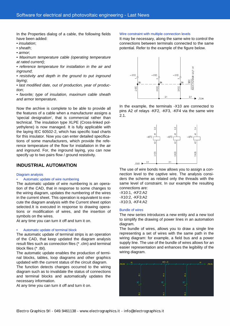
It may be necessary, along the same wire to control theconnections between terminals connected to the samepotential. Refer to the example of the figure below.
In the example, the terminals -X10 are connected topins A2 of relays -KF2, -KF3, -KF4 via the same wire2.1.
The use of wire bonds now allows you to assign a con-nection level to the captive wire. The analysis consi-ders the scheme as related only the threads with thesame level of constraint. In our example the resultingconnections are:-X10:1, -KF2:A2-X10:2, -KF3:A2-X10:3, -KF4:A2
Bundle of wires
The new series introduces a new entity and a new toolto simplify the drawing of power lines in an automationdiagram.The bundle of wires, allows you to draw a single linerepresenting a set of wires with the same path in thewiring diagram: for example, a field bus and a powersupply line. The use of the bundle of wires allows for aneasier representation and enhances the legibility of thewiring diagram.
Software for electrical and photovoltaic engineering - Last News
Electro Graphics Srl - 049.9461138 - www.electrographics.it - [email protected]
• Drawing bundle of wiresTo draw a bundle of wires run the Bundle of wires fun-ction. It is similar to the Wire function; in the Connec-tions dialog box you can set all wires data: section,color, type of junction,...The bundle of wires is characterized with a specific linetype, in order to improve the correct readability of thediagram. The default line type for the bundle of wires(EG_BUS line type) can be customized or replaced.
• Use of a single wire on a bundle of wiresTo draw a single wire that derives from a boundle ofwire, you can just run the FILO command and click theline of the boundle on the point of derivation. The pro-gram detects the connection to a bundle of wires anddisplays a dialog box where you can set the signal touse for the wire you are tracing. You can choose asignal from the list of the signals already present in thebundle or add a new one.
Executing the diagram analysis (automatic running fordefault) bundle of wires is marked with the pattern Bun-dle name [signals List] while each wire connected tothe bundle is market in with the pattern Bundlename.Signal name.
Rules for the Panel-Field orientation of components connec-ted to terminal boards
The analysis of the diagram processes for terminalwiring information in the circuit and determines the sideconnection of the components connected to the termi-nal blocks. The new rules for the orientation of the com-ponents connected to the terminal blocks will preventany devices are drawn in the wrong side of the termi-nal.
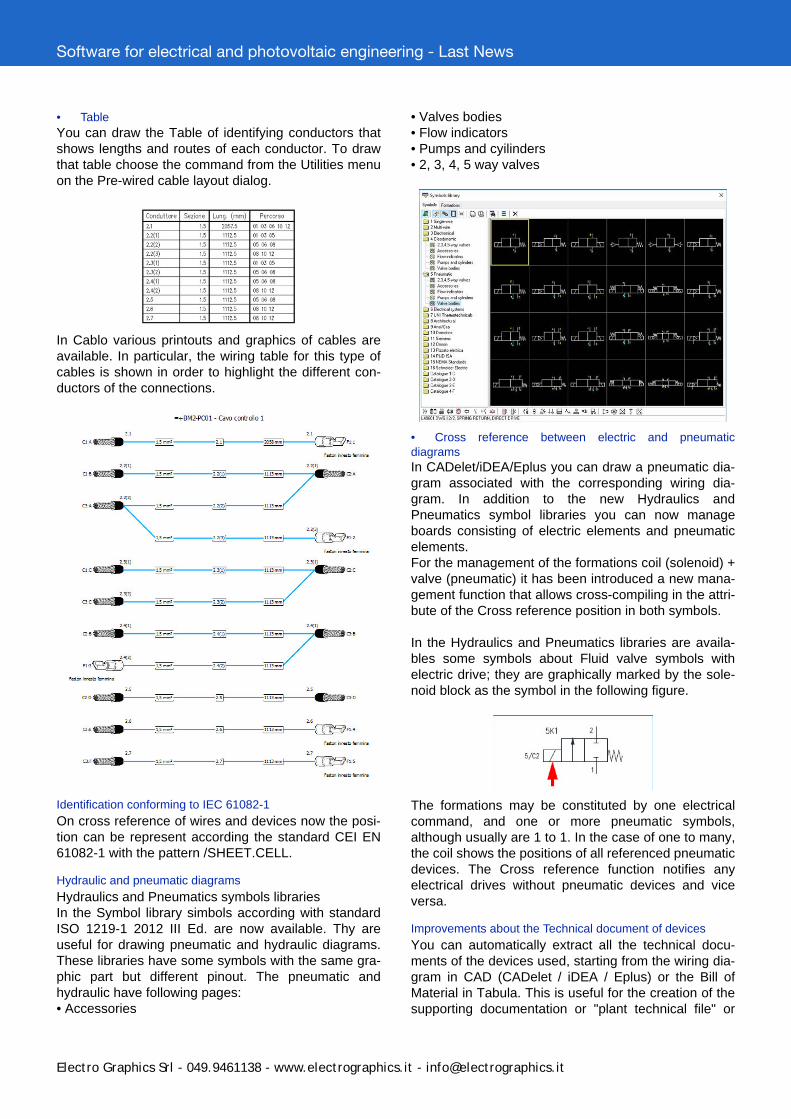
Setup of diagram analysis
The diagram analy-sis settings, and inparticular those refer-ring to the numbe-ring of wires, havebeen reorganized. Inthe Wire section dia-log box you cancustomize the assi-gnment between sec-tions of conductorsand color used fordraw it on the dia-gram and set whichsections must benumbered and whichnot. It is possibile tosave your settings indifferent profiles that can be recalled in other diagrams.
Marking of cable on drawing
The Marking of cable on drawing function allows you todraw a label representing the data of a cable and itsconductors. Before, you must execute the assignmentoof cable data to a wire line by the Define a cable on dra-wing function or by the software Cablo.You can customize the drawing characteristics of thelabel and save different profiles to be used for otherdiagrams.
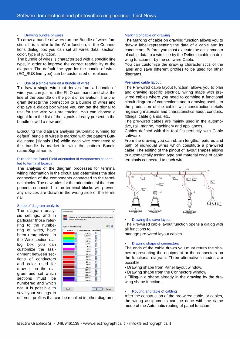
Pre-wired cable layout
The Pre-wired cable layout function, allows you to planand drawing specific electrical wiring made with pre-wired cables where you need to combine a functionalcircuit diagram of connections and a drawing usefull tothe production of the cable, with construction detailsregarding materials and characteristics about conduits,fittings, cable glands, etc.The pre-wired cables are mainly used in the automo-tive, rail, marine, machinery and appliances.Cables defined with this tool fits perfectly with Cablesoftware.From the drawing you can obtain lengths, features andpath of individual wires which constitute a pre-wiredcable. The editing of the pinout of layout shapes allowsto automatically assign type and material code of cableterminals connected to each wire.
• Drawing the cavo layoutThe Pre-wired cable layout function opens a dialog withall functions tomanage pre-wired layout cables.
• Drawing shape of connectorsThe ends of the cable drawn you must return the sha-pes representing the equipment or the connectors onthe functional diagram. Three alternatives modes arepossible.• Drawing shape from Panel layout window.• Drawing shape from the Connectors window.• Filling-in a shape already in the drawing by the dra-wing shape function.
• Routing and table of cablingAfter the construction of the pre-wired cable, or cables,the wiring assignments can be done with the samemode of the Automatic routing of panel function.
Software for electrical and photovoltaic engineering - Last News
Electro Graphics Srl - 049.9461138 - www.electrographics.it - [email protected]
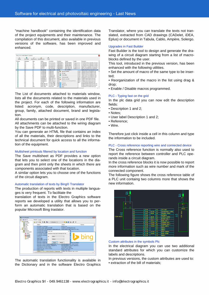
• TableYou can draw the Table of identifying conductors thatshows lengths and routes of each conductor. To drawthat table choose the command from the Utilities menuon the Pre-wired cable layout dialog.
In Cablo various printouts and graphics of cables areavailable. In particular, the wiring table for this type ofcables is shown in order to highlight the different con-ductors of the connections.
Identification conforming to IEC 61082-1
On cross reference of wires and devices now the posi-tion can be represent according the standard CEI EN61082-1 with the pattern /SHEET.CELL.
Hydraulic and pneumatic diagrams
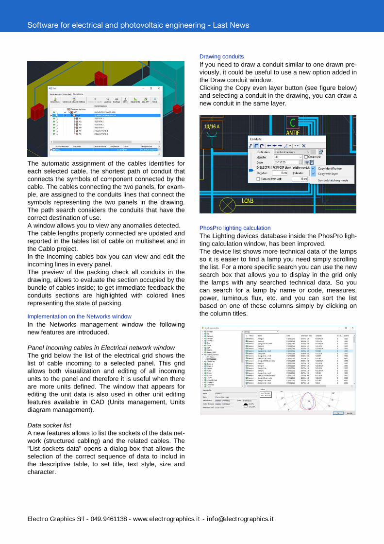
Hydraulics and Pneumatics symbols librariesIn the Symbol library simbols according with standardISO 1219-1 2012 III Ed. are now available. Thy areuseful for drawing pneumatic and hydraulic diagrams.These libraries have some symbols with the same gra-phic part but different pinout. The pneumatic andhydraulic have following pages:• Accessories
• Valves bodies• Flow indicators• Pumps and cyilinders• 2, 3, 4, 5 way valves
• Cross reference between electric and pneumaticdiagramsIn CADelet/iDEA/Eplus you can draw a pneumatic dia-gram associated with the corresponding wiring dia-gram. In addition to the new Hydraulics andPneumatics symbol libraries you can now manageboards consisting of electric elements and pneumaticelements.For the management of the formations coil (solenoid) +valve (pneumatic) it has been introduced a new mana-gement function that allows cross-compiling in the attri-bute of the Cross reference position in both symbols.
In the Hydraulics and Pneumatics libraries are availa-bles some symbols about Fluid valve symbols withelectric drive; they are graphically marked by the sole-noid block as the symbol in the following figure.
The formations may be constituted by one electricalcommand, and one or more pneumatic symbols,although usually are 1 to 1. In the case of one to many,the coil shows the positions of all referenced pneumaticdevices. The Cross reference function notifies anyelectrical drives without pneumatic devices and viceversa.
Improvements about the Technical document of devices
You can automatically extract all the technical docu-ments of the devices used, starting from the wiring dia-gram in CAD (CADelet / iDEA / Eplus) or the Bill ofMaterial in Tabula. This is useful for the creation of thesupporting documentation or "plant technical file" or
Software for electrical and photovoltaic engineering - Last News
Electro Graphics Srl - 049.9461138 - www.electrographics.it - [email protected]
"machine handbook" containing the identification dataof the project equipments and their maintenance. Thecompilation of this document, also available in previousversions of the software, has been improved andenhanced.
The List of documents attached to materials window,lists all the documents related to the materials used inthe project. For each of the following information arelisted: acronym, code, description, manufacturer,group, family, attached document, brand and legisla-tion.All documents can be printed or saved in one PDF file.All attachments can be attached to the wiring diagramby the Save PDF to multi-function.You can generate an HTML file that contains an indexof all the materials, their descriptions and links to thetechnical document for quick access to all the informa-tion of the equipment.
Multisheet printouts filtered by location and function
The Save multisheet as PDF provides a new optionthat lets you to select one of the locations in the dia-gram and then print only the sheets in which there arecomponents associated with that location.A similar option lets you to choose one of the functionsof the circuit diagram.
Automatic translation of texts by Bing® Translator
The production of reports with texts in multiple langua-ges is very frequent. To facilitate thetranslation of texts in the Electro Graphics softwarereports we developed a utility that allows you to per-form an automatic translation that is based on thepopular Microsoft Bing traslator.
The automatic translation functionality is available inthe Dictionary and in the software Electro Graphics
Translator, where you can translate the texts not tran-slated, extracted from CAD drawings (CADelet, iDEA,Eplus) or document in Tabula, Cablo, Ampère, Solergo.
Upgrades in Fast Builder
Fast Builder is the tool to design and generate the dra-wing of a circuit diagram starting from a list of macro-blocks defined by the user.This tool, introduced in the previous version, has beenenhanced with the following utilities.• Set the amount of macro of the same type to be inser-ted;• Reorganization of the macro in the list using drag &drop;• Enable / Disable macros programmed.
PLC - Typing fast on the grid
In the plc data grid you can now edit the descriptionfields:• Description 1 and 2;• Notes;• User label Description 1 and 2;• Reference;• Wire.
Therefore just click inside a cell in this column and typethe information to be included.
PLC - Cross reference reporting wire and connected device
The Cross reference function is normally also used toreport the reference between controller and PLC ope-rands inside a circuit diagram.In the cross reference blocks it is now possible to reportmore information such as wire number and mark of theconnected component.The following figure shows the cross reference table ofa PLC unit containg two columns more that shows thenew information.
Custom attributes in the symbols Plc
In the electrical diagram you can use two additionalstandard attributes for which you can customize thelabels and descriptions.In previous versions, the custom attributes are used to:• extraction of the bill of materials;

Software for electrical and photovoltaic engineering - Last News
Electro Graphics Srl - 049.9461138 - www.electrographics.it - [email protected]
• update the attributes in the drawing with the data ofthe bill of materials;• draw of the synoptic representations;• draw the cross reference tables.Now, the defined custom attributes may also be filledfor racks, boards and operands Plc, editing data in thesoftware Electro Graphics Plc. When drawing Plc theyare automatically added as new attributes on therespective symbols. No need to customize the symbolsof the PLC blocks.
ELECTRICAL SYSTEMS
Compositions library
The Compositions of symbols for plants library allowsyou to easily create combinations of symbols to repre-sent modular devices and wiring accessories(switches, sockets) inside a box. A composition can optionally contain more independentboxes installed at different elevations, thus reproducinga "column" of wiring accessory boxes. The followingfigure shows an example of composition created bythree boxes, respectively, with two sockets, twoswitches and one thermostat installed at differentheights.
Each element of the composition may have an associa-ted computation code or, alternatively, a material codeto allow the extraction of the estimate, to be processedlater with the Sigma software.The rectangle that represents the box can be connec-ted to cable conduits as any symbol of plant enginee-ring and can be associated with one or moredistribution devices using electrical The composition ofboxes is full customizable and can be saved in theCompositions library, organized into folders and subfol-ders.
Following picture shows a detail of a plant of an apart-ment designed with the aid of the composition of boxeslibrary.
Diagram cables
The new Diagram cables page, in the Networks inter-face window manages the laying of cables defined inthe electrical diagram inside the conduits on a systemlayout or a 3d layout of a machine.The multi-sheet wiring diagram is processed and con-verted into a network formed by the panels and theboard machine elements detected. These elements areconnected with the appropriate cables defined in thewiring diagram. At this point you can associate eachtransition element (panel, junction box, equipment)acquired from the circuit diagram to a block inserted inan other drawing with the plant layout.The following figure shows the layout of an automationsystem where it was executed the laying of cablesacquired from the circuit diagram.
Software for electrical and photovoltaic engineering - Last News
Electro Graphics Srl - 049.9461138 - www.electrographics.it - [email protected]
The automatic assignment of the cables identifies foreach selected cable, the shortest path of conduit thatconnects the symbols of component connected by thecable. The cables connecting the two panels, for exam-ple, are assigned to the conduits lines that connect thesymbols representing the two panels in the drawing.The path search considers the conduits that have thecorrect destination of use.A window allows you to view any anomalies detected.The cable lengths properly connected are updated andreported in the tables list of cable on multisheet and inthe Cablo project.In the Incoming cables box you can view and edit theincoming lines in every panel.The preview of the packing check all conduits in thedrawing, allows to evaluate the section occupied by thebundle of cables inside; to get immediate feedback theconduits sections are highlighted with colored linesrepresenting the state of packing.
Implementation on the Networks window
In the Networks management window the followingnew features are introduced.
Panel Incoming cables in Electrical network windowThe grid below the list of the electrical grid shows thelist of cable incoming to a selected panel. This gridallows both visualization and editing of all incomingunits to the panel and therefore it is useful when thereare more units defined. The window that appears forediting the unit data is also used in other unit editingfeatures available in CAD (Units management, Unitsdiagram management).
Data socket listA new features allows to list the sockets of the data net-work (structured cabling) and the related cables. The"List sockets data" opens a dialog box that allows theselection of the correct sequence of data to includ inthe descriptive table, to set title, text style, size andcharacter.
Drawing conduits
If you need to draw a conduit similar to one drawn pre-viously, it could be useful to use a new option added inthe Draw conduit window. Clicking the Copy even layer button (see figure below)and selecting a conduit in the drawing, you can draw anew conduit in the same layer.
PhosPro lighting calculation
The Lighting devices database inside the PhosPro ligh-ting calculation window, has been improved.The device list shows more technical data of the lampsso it is easier to find a lamp you need simply scrollingthe list. For a more specific search you can use the newsearch box that allows you to display in the grid onlythe lamps with any searched technical data. So youcan search for a lamp by name or code, measures,power, luminous flux, etc. and you can sort the listbased on one of these columns simply by clicking onthe column titles.
Software for electrical and photovoltaic engineering - Last News
Electro Graphics Srl - 049.9461138 - www.electrographics.it - [email protected]
ELECTRIC CALCULATION - Ampère line
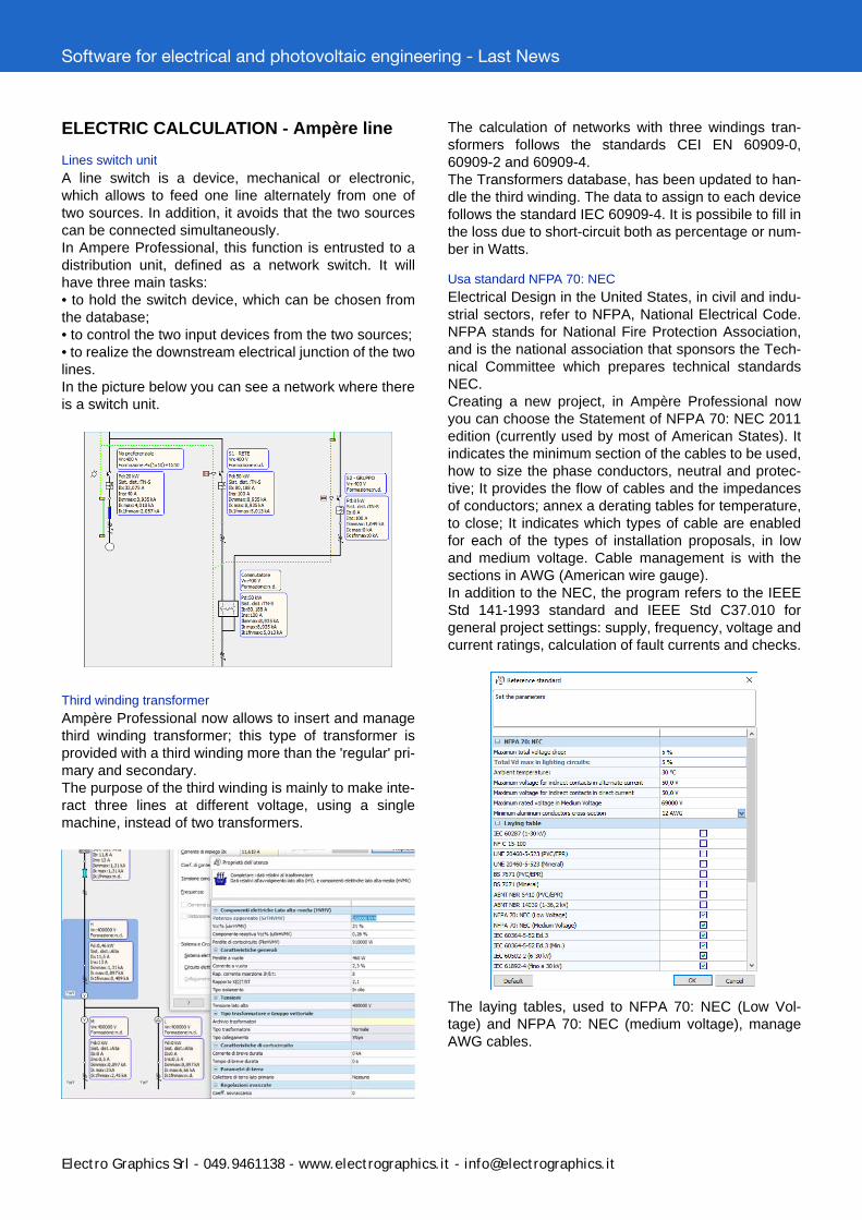
Lines switch unit
A line switch is a device, mechanical or electronic,which allows to feed one line alternately from one oftwo sources. In addition, it avoids that the two sourcescan be connected simultaneously.In Ampere Professional, this function is entrusted to adistribution unit, defined as a network switch. It willhave three main tasks:• to hold the switch device, which can be chosen fromthe database;• to control the two input devices from the two sources;• to realize the downstream electrical junction of the twolines.In the picture below you can see a network where thereis a switch unit.
Third winding transformer
Ampère Professional now allows to insert and managethird winding transformer; this type of transformer isprovided with a third winding more than the 'regular' pri-mary and secondary.The purpose of the third winding is mainly to make inte-ract three lines at different voltage, using a singlemachine, instead of two transformers.
The calculation of networks with three windings tran-sformers follows the standards CEI EN 60909-0,60909-2 and 60909-4.The Transformers database, has been updated to han-dle the third winding. The data to assign to each devicefollows the standard IEC 60909-4. It is possibile to fill inthe loss due to short-circuit both as percentage or num-ber in Watts.
Usa standard NFPA 70: NEC
Electrical Design in the United States, in civil and indu-strial sectors, refer to NFPA, National Electrical Code.NFPA stands for National Fire Protection Association,and is the national association that sponsors the Tech-nical Committee which prepares technical standardsNEC.Creating a new project, in Ampère Professional nowyou can choose the Statement of NFPA 70: NEC 2011edition (currently used by most of American States). Itindicates the minimum section of the cables to be used,how to size the phase conductors, neutral and protec-tive; It provides the flow of cables and the impedancesof conductors; annex a derating tables for temperature,to close; It indicates which types of cable are enabledfor each of the types of installation proposals, in lowand medium voltage. Cable management is with thesections in AWG (American wire gauge).In addition to the NEC, the program refers to the IEEEStd 141-1993 standard and IEEE Std C37.010 forgeneral project settings: supply, frequency, voltage andcurrent ratings, calculation of fault currents and checks.
The laying tables, used to NFPA 70: NEC (Low Vol-tage) and NFPA 70: NEC (medium voltage), manageAWG cables.
Software for electrical and photovoltaic engineering - Last News
Electro Graphics Srl - 049.9461138 - www.electrographics.it - [email protected]
The US networks, in addition to being operated at 60Hz, make extensive use of electric circuits 2F + N andthe transformers with center socket w/Center, to whichconnect the neutral wire. Furthermore, the neutral toearth is normally executed with the TN system.
Laying tables
Two new laying tables have been added to manage thethird edition (2009) of IEC 60364-5-52: one for plasticinsulated cables and one for mineral insulated cables.Totally new are the laying tables of IEC 60502-2 stan-dards for medium voltage cables (6-30 kV) and IEC61892-4 for offshore cables, in low and medium voltageup to 30 kV.To use the laying tables, you must activate them in theReference standard window, called up from the Rulesand global constants tab in the Properties window.Now you can use the standard IEC 35024/1 UNEL foraluminum cables for the poses in the air, by applyingthe same coefficient of 0.78 to the data for the ingroundlaying.
Reverse sequence in the calculation of the fault
In the calculation of non-symmetrical fault currents,Ampère now also considers the negative sequence ofthe impedances, instead of approximate it equal to thedirect sequence. This step improves the calculation inthe presence of rotating machines, such as generatorsand synchronous or asynchronous motors. In them theinverse impedance is always comparable to the sub-transient impedance values, especially during the per-manent fault.Now Ampère manages the reactance of rotating syn-chronous machines at the zero sequence.
Cables database
For the cables are now handled more properties: Isola-tor type, Maximum temperature of cable, Sheath andArmor. The section Capacities has been expanded, inorder to fill in more detailed specifications provided bysome manufacturers: reference temperature of the flowfor laying in air and inground. For laying inground isnow possible to specify up to two pairs flow / groundresistivity.
XLPE isulation
The introduction of the laying IEC 60502-2 table hasrequested the insulator management XLPE (Cross-lin-ked polyethylene). The XLPE insulation has beenextended to all compatible laying tables, although infact only changes the ability to filter into the cable adap-ter.
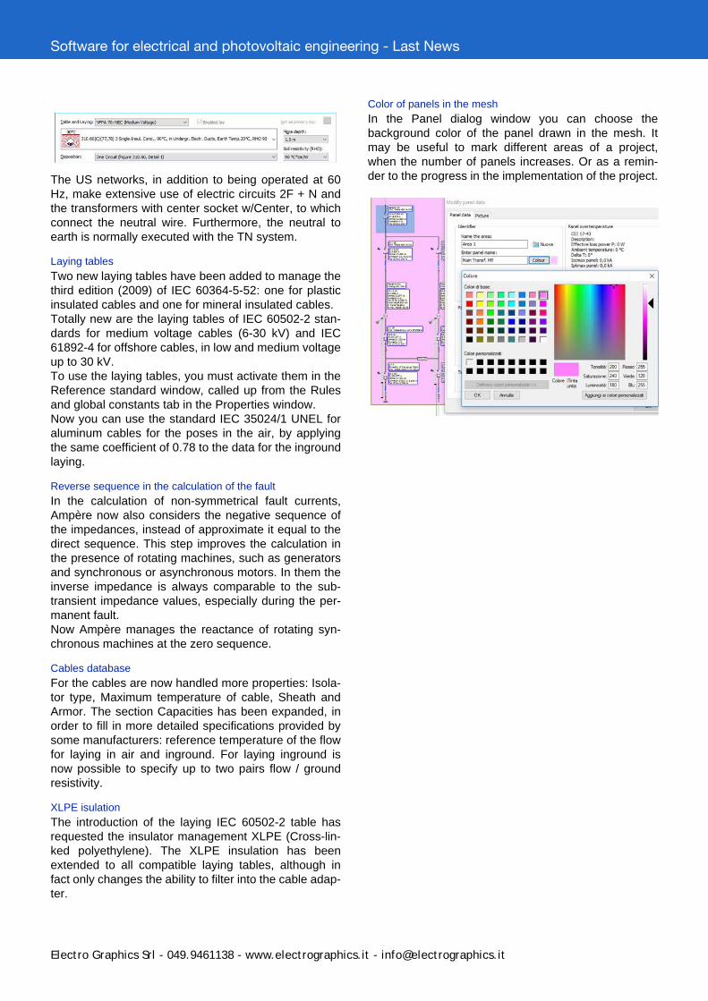
Color of panels in the mesh
In the Panel dialog window you can choose thebackground color of the panel drawn in the mesh. Itmay be useful to mark different areas of a project,when the number of panels increases. Or as a remin-der to the progress in the implementation of the project.

Software for electrical and photovoltaic engineering - Last News
Electro Graphics Srl - 049.9461138 - www.electrographics.it - [email protected]
PHOTOVOLTAIC ENGINEERING
Power optimizer
The power optimizer is a DC/DC converter connectedto each photovoltaic module replacing the junction box.The power optimizers increase the energy produced bythe photovoltaic system by acting as impedance adap-ter and constantly monitoring the maximum power point(MPPT) for each module. In addition, some power opti-mizers, monitor the performance of each module andcommunicate to the inverter the performance data inorder to improve the cost-benefit ratio in the modulemaintenance. The maximum power point (MPPT) foreach module allows flexible system design with multi-ple orientations, inclinations.
Database of power optimizer
Power optimizers used in photovoltaic systems are atype of converter, so in Solergo they are included theConverters database. In addition to the default devicesyou can add more power optimizer filling in the datarequired.
System with power optimizer
In the configuration of a photovoltaic system withSolergo, inside the Components page, you can now setthe use of power optimizers.Once you choose the PV module you can activate thecheck box Use power optimizer; a drop-down list sug-gests all non-integrated optimizers compatible with thepreviously selected PV module. If the selected PVmodule has a built-in optimizer, Solergo automaticallyswitches to the use of the optimizer.
Electrical checks in syetem with power Optimizers
Below is the list of electrical tests performed by Solergoin the presence of the power optimizers.• Input power: maximum input power (maximum powerof the module or group of modules) must be less thanthe nominal power DC optimizer.• Lower voltage limit: minimum operating voltage of thepv module (Vn min) must be greater than the lower limitof the optimizer.• Maximum voltage: Maximum working voltage (Vnmin) of the pv module must be less than the maximuminput voltage optimizer.• Maximum vacuum operating voltage (Voc max) of thepv module must be less than the maximum input vol-tage optimizer.• Maximum module output current (Isc max) must beless than the maximum current in the optimizer input.• Maximum output current by the optimizer (ratio ofinstalled power and voltage input inverter DC) must beless than the maximum current available in the optimi-zer output.• Limits of elements in series (minimum, maximum andmaximum power per string) must be according to indi-cations of the house.
Producibility of system with power optimizers
In the presence of power optimizers the loss due tomismatching and decoupling of the modules are resetto zero. In the case of close shading, the power optimi-zers allow to limit the loss only to the shaded modules,without affect the producibility of the whole string ofmodules. This phenomenon is considered in the simu-lations for evaluation of losses due to close shadowsonly considering the loss of the direct components ofirradiation in shaded modules.
Alignment to standard UNI 10349-1 2016 (italy)
The climate database in Solergo has been aligned tostandard UNI 10349-1:2016 e UNI 10349-2:201.The UNI 10349-1 provides, for the Italian territory, theconventional climatic data required for checking theenergy performance of buildings. The standard alsoprovides the calculation methods to:• split the solar irradiance into direct and diffuse compo-nent.• calculate the radiant energy received from a inclinedand oriented fixed surface.

Software for electrical and photovoltaic engineering - Last News
Electro Graphics Srl - 049.9461138 - www.electrographics.it - [email protected]
COMPUTATION
Concatenated material codes
An item in the bill of materials now can be an assem-bled article, so it can contain several materials codes.These items can be extracted from a circuit diagram, sofrom symbols with more material codes concatenatedin the Main code attribute, or be composed in Tabula.Editing a distinct material item with several codes, inthe Article tab, the main code box displays the list ofassembled material codes. You can edit the code listusing the button Archive materials aside, allows you toadd, edit or delete each item.
Multiple alternative codes
For each material item now you can fill up to three alter-native codes. You can code the items with custom codeto suit your needs and warehouse management.When editing an article in the Articles database in theAlternative code the new menu with boxes allows youto compile the custom codes.
News about printpouts
The window for the launch of Tabula printouts has beenimproved on the appearance by rearranging the layoutof the many options available, in order to make themost clear and simple interface configuration to getpersonalized documents faster and more intuitive way.A number of options have been added to in order to fur-ther extend the customization of the printouts. Theseoptions are valid for custom templates.- Adapt row height- Distances lines with different device-mark- New page at Location change- Group by Location and FunctionSome options have been grouped in a form that can beopen with the Advanced button. New are the followingoptions.- Print alternative code- Do not print item descriptions not translated