software engineering - university of cape town · pdf filesoftware testing ... flow graphs,...
TRANSCRIPT

Software Engineering
The Department of Computer Science, University of Cape Town

Software Engineeringby The Department of Computer Science, University of Cape Town
Publication date 2010Copyright © 2005-2010 University of Cape Town

iii
Table of Contents1. Introduction .............................................................................................................. 1
Objectives ............................................................................................................ 1Introduction ......................................................................................................... 1Information systems and software ............................................................................ 1
The importance of software engineering ............................................................ 2Systems ....................................................................................................... 2
System boundaries ................................................................................................ 3Categories of information system and software programs ............................................ 4
Information systems ...................................................................................... 4Legacy systems .................................................................................................... 6The benefits of software systems ............................................................................. 7
Tactical benefits ........................................................................................... 7Strategic benefits .......................................................................................... 7
The reasons for change .......................................................................................... 8Software myths ..................................................................................................... 8
Management myths ....................................................................................... 8Customer / end-user myths ............................................................................. 8Programmer myths ........................................................................................ 9
Review ................................................................................................................ 9Questions .................................................................................................... 9Answers ..................................................................................................... 12
2. Process and Model ................................................................................................... 16Objectives .......................................................................................................... 16The software crisis ............................................................................................. 16
The code-and-fix approach to software development .......................................... 16Software engineering and the software process ....................................................... 17
The layers of software engineering ................................................................. 18A generic framework of the software process ................................................... 19
Software models ................................................................................................. 20Prescriptive and agile models ........................................................................ 20Computer Aided Software Engineering: CASE ................................................. 31
Review .............................................................................................................. 35Questions ................................................................................................... 35Answers ..................................................................................................... 36
3. Requirements Engineering ......................................................................................... 38Objectives .......................................................................................................... 38Requirements engineering ..................................................................................... 38What is requirements engineering? ......................................................................... 38The steps in detail ............................................................................................... 39
Inception .................................................................................................... 39Elicitation .................................................................................................. 40Elaboration ................................................................................................. 40Negotiation ................................................................................................ 40Specification ............................................................................................... 40Validation .................................................................................................. 40Management ............................................................................................... 41
Use case modeling .............................................................................................. 41Use case modeling in the UML specification .................................................... 41
Review .............................................................................................................. 55Questions ................................................................................................... 55Answers ..................................................................................................... 56
4. An Introduction to Analysis and Design ....................................................................... 58Objectives .......................................................................................................... 58Introduction ........................................................................................................ 58
System analysis ......................................................................................... 58

Software Engineering
iv
System design ............................................................................................. 58The relation between analysis and design ......................................................... 58
Introduction to models ......................................................................................... 59Definition of the term “model” ...................................................................... 59
The properties of models ...................................................................................... 60Model properties: maintainability and disposability .......................................... 60Model properties: graphics and text ................................................................ 61Model properties: comprehension ................................................................... 61
The main models of traditional analysis and design ................................................... 61Class model ............................................................................................... 62Data-flow diagram ....................................................................................... 62Sequence diagrams ...................................................................................... 63Useful points .............................................................................................. 64
The benefits of using formal models ....................................................................... 64Case studies ....................................................................................................... 64Review .............................................................................................................. 65
Questions ................................................................................................... 65Answers ..................................................................................................... 65
5. Object-oriented Analysis and Design ........................................................................... 67Objectives .......................................................................................................... 67Introduction ........................................................................................................ 67Modelling standpoints .......................................................................................... 67Classes and objects .............................................................................................. 68
Classification .............................................................................................. 68Classification in object-oriented design ............................................................ 69A definition of class and object .................................................................... 69Examples of classes ..................................................................................... 69Some thoughts on the relationship between classes and objects ............................ 70
Concrete and conceptual classes ............................................................................. 70Attributes ........................................................................................................... 71Operations .......................................................................................................... 73Dynamic behaviour and state ................................................................................. 73UML notation and conventions .............................................................................. 74
Symbol ...................................................................................................... 74Naming conventions .................................................................................... 75
Finding classes ................................................................................................... 76Relationships between classes ................................................................................ 76Specifying relationships in detail ............................................................................ 77Inheritance ......................................................................................................... 78Abstract classes ................................................................................................... 79Aggregation and composition ................................................................................ 80
Aggregation ................................................................................................ 80Composition ............................................................................................... 80
Self-association and roles ..................................................................................... 81Link classes and link attributes .............................................................................. 81Constraints and notes ........................................................................................... 82
Notes ........................................................................................................ 82Constraints ................................................................................................ 82
Class-Responsibility-Collaborator cards ................................................................... 82From model to program ....................................................................................... 83Dynamic behaviour .............................................................................................. 83
Interaction diagrams .................................................................................... 83Summary ................................................................................................... 84
Review .............................................................................................................. 85Questions ................................................................................................... 85Answers ..................................................................................................... 88
6. Data-Flow Diagrams ................................................................................................ 93Objectives .......................................................................................................... 93

Software Engineering
v
Introduction to data-flow diagrams ........................................................................ 93What are data-flow diagrams? ...................................................................... 93An example data-flow diagram ..................................................................... 93The benefits of data-flow diagrams ................................................................. 94
Case study ......................................................................................................... 95The different kinds (and levels) of data-flow diagrams ............................................... 95Elements of data-flow diagrams ............................................................................. 95
Processes .................................................................................................. 96Data-flows ................................................................................................. 97Data stores ................................................................................................. 98External entities ......................................................................................... 99Multiple copies of entities and data stores on the same diagram .......................... 99
Context diagrams .............................................................................................. 100What is a context diagram? ........................................................................ 100Constructing a context diagram .................................................................... 100
Level 1 data-flow diagrams ................................................................................ 101What is a level 1 DFD? ............................................................................. 101Constructing level 1 DFDs ......................................................................... 101
Decomposing diagrams into level 2 and lower hierarchical levels .............................. 102What is a level 2 (or lower) DFD? .............................................................. 102Constructing level 2 (and lower) DFDs — functional decomposition .................. 103
Making levels ................................................................................................... 103Balancing ......................................................................................................... 104Numbering ....................................................................................................... 104Process descriptions ........................................................................................... 105Validation ........................................................................................................ 105An example in constructing a data-flow diagram ..................................................... 106
Identify the system boundaries ..................................................................... 106Follow inputs ........................................................................................... 107Follow events .......................................................................................... 107Fill in gaps ............................................................................................... 108Repeat .................................................................................................... 108
Review ............................................................................................................ 109Questions ................................................................................................. 109Answers ................................................................................................... 112
7. Design ................................................................................................................. 129Objectives ........................................................................................................ 129Introduction ...................................................................................................... 129Abstraction ....................................................................................................... 129Architecture ...................................................................................................... 129Patterns ............................................................................................................ 130Modularity ........................................................................................................ 130Information hiding ............................................................................................. 131Functional independence ..................................................................................... 131Stepwise refinement ........................................................................................... 131Refactoring ....................................................................................................... 132Design classes ................................................................................................... 132Review ............................................................................................................ 133
Questions ................................................................................................. 133Answers ................................................................................................... 133
8. Design Patterns ...................................................................................................... 135Objectives ........................................................................................................ 135Introduction to design patterns ............................................................................. 135
The idea of a pattern .................................................................................. 135The origins of design patterns ...................................................................... 137Patterns in software design .......................................................................... 138
Design patterns in object-oriented programming ...................................................... 139Definitions of terms and concepts ................................................................. 139

Software Engineering
vi
Scope of development activity: applications, toolkits, frameworks ..................... 140Pattern classifications and pattern catalogue .................................................... 140Behavioural patterns ................................................................................... 141Creational patterns ..................................................................................... 143Structural patterns ...................................................................................... 144How to use a design pattern ........................................................................ 145
Patterns in Java ................................................................................................. 145The Observer pattern in Java ....................................................................... 145The Model-View-Controller pattern .............................................................. 149Abstract factory facilities in Java .................................................................. 150Composite patterns in Java .......................................................................... 151
Review ............................................................................................................ 152Questions ................................................................................................. 152Answers ................................................................................................... 154
9. Software Testing .................................................................................................... 156Objectives ........................................................................................................ 156Introduction to software testing ............................................................................ 156The testers ........................................................................................................ 156
The developers .......................................................................................... 156An independent testing team ........................................................................ 157The customer ............................................................................................ 157
Principles of software testing ............................................................................... 157The completion of software testing ............................................................... 157Writing testable software ............................................................................ 158Test cases and test case design ..................................................................... 158
Testing strategies ............................................................................................... 158Unit testing ............................................................................................... 159Integration testing ...................................................................................... 159Validation testing ...................................................................................... 160System testing ........................................................................................... 160
Testing advice ................................................................................................... 160Flow graphs, cyclomatic complexity and white-box testing .............................. 161Black-box testing ....................................................................................... 164Object-oriented testing ................................................................................ 165
Debugging ........................................................................................................ 165Brute force debugging ................................................................................ 165Backtracking ............................................................................................. 165Cause elimination ...................................................................................... 165Bisect ...................................................................................................... 166
Review ............................................................................................................ 166Questions ................................................................................................. 166Answers ................................................................................................... 167

vii
List of Figures1.1. A diagrammatic representation of a system .................................................................. 32.1. The code-and-fix approach ...................................................................................... 162.2. The process with requirements ................................................................................. 172.3. The layers of software engineering ........................................................................... 192.4. The waterfall method ............................................................................................. 212.5. The incremental development software model ............................................................ 222.6. Disposable prototyping ........................................................................................... 252.7. SELECT-Enterprise screenshot ................................................................................ 322.8. Java code ............................................................................................................. 332.9. A command-line Java interpreter .............................................................................. 333.1. Actor representations ............................................................................................. 433.2. The system boundary ............................................................................................. 463.3. Representations of use cases ................................................................................... 473.4. Use case association .............................................................................................. 483.5. Use of stereotypes in use case relationships ............................................................... 483.6. A use case example, without generalisation ............................................................... 513.7. Use case generalisation .......................................................................................... 513.8. Use case example, with generalisation ...................................................................... 523.9. A full example ..................................................................................................... 533.10. Without generalisation .......................................................................................... 553.11. With generalisation .............................................................................................. 564.1. An example class model of an estate agency .............................................................. 624.2. An example of a data-flow diagram .......................................................................... 634.3. An example of a sequence diagram .......................................................................... 635.1. The UML symbol for a class ................................................................................... 745.2. A relationship between two classes ........................................................................... 765.3. Indicating multiplicity ............................................................................................ 775.4. Generalisation-specialisation represented in the UML ................................................... 785.5. The representation of aggregation in the UML ............................................................ 805.6. The representation of composition in the UML ........................................................... 805.7. Link attributes ...................................................................................................... 815.8. The notation for notes ............................................................................................ 825.9. Sequence diagram notation in the UML .................................................................... 846.1. An example data-flow diagram ................................................................................ 946.2. The notation for a process ...................................................................................... 966.3. Notation for a data-flow ......................................................................................... 976.4. Notation for a data store ......................................................................................... 986.5. Notation for external entities ................................................................................... 996.6. How to notate duplicated external entities .................................................................. 996.7. How to notate duplicate data stores ......................................................................... 1006.8. A context diagram for Video-Rental LTD ................................................................ 1006.9. A level 1 DFD for Video-Rental LTD ..................................................................... 1016.10. A level 2 data-flow diagram for Video-Rental LTD ................................................. 1026.11. Find the external entities ..................................................................................... 1098.1. A simple pattern for a bridge ................................................................................. 1358.2. The girder .......................................................................................................... 1368.3. The arch ............................................................................................................ 1368.4. Suspension ......................................................................................................... 1368.5. Subdivision ........................................................................................................ 1378.6. Narrowing .......................................................................................................... 1378.7. The Forth Bridge ................................................................................................. 1378.8. Class diagram of the Observer pattern ..................................................................... 1428.9. Class diagram for the Abstract Factory pattern .......................................................... 1448.10. Class diagram of the Composite pattern ................................................................. 1448.11. The ECG Observer ............................................................................................ 147

Software Engineering
viii
8.12. Java output of screen and font information ............................................................. 1508.13. java.awt GUI components containers and layout managers ........................................ 1519.1. Flow graph notation ............................................................................................. 1629.2. An example flow-graph ........................................................................................ 163

ix
List of Tables8.1. Design patterns according to Gamma et. al. .............................................................. 1418.2. Observable class methods in java.util.package .......................................................... 146

1
Chapter 1. IntroductionObjectives
At the end of this chapter you will have acquired an introductory understanding of what software andsoftware engineering are, as well as an understanding of some of the common myths surrounding thepractice of software engineering.
IntroductionIt could be argued that information systems are vital components of any civilisation. The humandesire to record information goes back thousands of years to when humans first started painting onstones. However, it is the practice of recording and displaying information in a systematic mannerthat warrants the use of the term “information system”. Such practices can be easily found in greatcivilisations, such as those of ancient Egypt, Greece and Rome.
The development and use of information technology (IT) has led to the birth of new generationsof information systems. Computer-based information systems (software systems) have dramaticallyinfluenced our behaviour and the way in which we conduct every day activity. It is not surprising thatthe standing of any society in the world is now strongly linked to the level of penetration that softwaresystems have in that society.
In this module we shall use term software systems to refer to information systems that contain ormight contain software components. Although there are many information systems that do not involvecomputers, such as a card filing system of a small library or a manager's list of contacts, almost allmodern information systems either use computers, or could use computers, to perform some of theirfunctions (such as cash registers for point-of-sales processing, and stock control systems for smallbusinesses).
Further, while we will occasionally mention information systems, this module is ultimately interestedin the software components of an information system, and how to engineer software that can bereliably used by other people. Software is integral to computerised information systems. Withoutthe underlying software, the system will not be able to do what its users intend, and if the softwarefunctions incorrectly, so will the information system.
Information systems and softwareSoftware systems are made up of the following components:
• Users — the people who add information to the system, request information from the system, andperform some of the information processing functions.
• Procedures – the tasks performed by the human components of the information system.
• Information – meaningful data that the system stores and processes.
• Documents – manuals on how to use the system, sometimes even files of data which should notor could not be stored electronically.
• Hardware – not only the computers in the system but also any networks linking the computers,the input devices and output devices.
• Software – computer applications performing some of the system functions to record, process, andregulate access to some of the information worked with by the information system
Importantly, we need to consider what software is. Software is typically defined to be instructionsthat provide desired features, functions, and performance. They contain data structures which allow

Introduction
2
the software program to manipulate the information contained in an information system. Importantly,software also includes documentation describing how the software performs the actions that it does,and how the software may be used. Notice that some of the documentation is for the software's users,while other portions of the documentation are for its developers and maintainers.
There are some important properties of software that you should consider when thinking of thediscipline of software engineering.
• First, software is engineered rather than manufactured. Once the software has been developed, thereremains no significant “manufacturing” process that could possibly lower the software's quality(i.e., introduce software errors, cause the software to deviate from what the customer requested, andso on). The cost of developing software lies almost completely in the engineering of the software,and not in the “manufacturing” of a “product” that customers can be hold in their hands.
• Software does not wear out with use, as hardware might. However, this does not mean that softwaredoes not degrade over time. A software program is continuously changed over its lifetime. Ifthese changes occur too frequently, the bugs introduced by each change may slowly degrade theperformance and utility of the software as a whole. Also, when software degrades in quality, thereare no “spare parts” which can be used as replacements.
• Unlike hardware, most software remains custom built, rather than built using “off the shelf”components.
The importance of software engineeringOver the last few decades, software systems and the software that run them have become an importantcomponent to many aspects of our society, from commerce to medicine, engineering, the sciences andentertainment.
Importantly, the infrastructure of all developed countries rely heavily on software systems. Because ofthis, it is important that the software we use and rely on are of a high quality and fulfil our requirementsof them. Gaining this high quality does not happen randomly or by accident — rather we need toengineer that quality into the software that we use.
When software fails, people may be bankrupted and even killed (consider safety critical systemswhich run planes, medical equipment, and so on). Because so much depends on software, softwarehas become important to business and the economy. This means that the software engineer is alwayspart of a larger environment, consisting of customers, other software engineers, managers, and so on.It is important that the engineer be able to interact appropriately with all of these individuals, and this,too, is part of software engineering.
SystemsBecause information systems are what we build using software, it is important to consider exactlywhat it is that we are building: what is a system?
The word system is used regularly to refer to a coherent group of elements (or components) thattogether aim to achieve a certain objective, or to have a specific purpose. A more rigorous definitionwould describe a system as a group or combination of interrelated, interdependent or interactingelements forming a collective entity (a whole) with a control mechanism that helps the system achieveits goal.
Systems live in environments that are relevant to their existence. They receive inputs from theenvironment, and produce outputs for the environment. Systems tend to have a boundary that isdefined in relation to the external environments in which they reside. The survival of a system relieson a control mechanism that regulates the processes of receiving inputs and producing outputs usingfeedback.
Figure 1.1, “A diagrammatic representation of a system” illustrates many of the important featuresof a system:

Introduction
3
• There may be many different inputs
• There may be many different outputs
• The system is composed of interconnected components — the components may be of differentkinds.
• Some of the outputs of the system are fed back into the system, so that the system can control itselfand make corrective changes when unexpected or undesirable outputs occur
Figure 1.1. A diagrammatic representation of a system
These components play a role in the software that we create: the inputs to the system will becomeinputs to the software. The outputs of the software will eventually be the system's outputs.
System boundariesThe smaller the system, the sharper its boundary. Large systems may have multiple boundaries as theyinterface with multiple systems. The boundary also depends on the point from which it is viewed inrelation to other systems with which it interfaces.
An example of the complexity and difficulties of defining system boundaries is the ATM (automatedteller machines). Consider the following candidates for system boundary:
• The physical machine itself
• The customer and the machine
• The machine and the bank's local database of customer accounts
• The machine and the bank's national network and central database of transactions and accountbalances
• The machine and the staff that loan and run regular software checks of the machine
Which of the above might be the “right” boundary for the analysis of the system in which the ATM iscentral? Different analysts may choose different boundaries, and these boundaries may change duringtalks with the customers wanting the system built, and with the ultimate end-users of the system. Animportant skill which systems analysts and software engineers must develop is to determine whichboundaries are important to consider.
The software which we as software engineers develop are only a component of larger informationsystems in an organisation or group. This module concerns itself with the development and engineeringof software, but to effectively engineer such software we must be able to understand the informationsystem as a whole, and relate the software to it.
For effective and successful software engineering, software engineers have the difficult job of learninghow the information system users perform their daily jobs, as well the tasks they attempt to achieve.

Introduction
4
If the software does not support the users in their tasks, then the software will not be used, and thesoftware development has failed.
American Federal Aviation Authority example
During the development of the American Federal Aviation Authority (FAA) automated flightcontrol system software engineers tried to produce electronic counterparts for the flight strips— little bits of paper giving details of a particular flight which would be moved betweenoperators and used for quick reference. This task proved to be impossible and the final systemnot only still has these bits of paper but the consoles have special slots to put them in.
This example illustrates an important point; that is any artificial system has a boundary whichdefines what is part of it and what is not. Sometimes this boundary is clear cut, say whenthe computer screen and keyboard are the boundary for a system, other times it is not, saywhen people and bits of paper form an integral part of the system. In the case of the FAAsystem some of the functions that were considered part of the system are solely performedby humans, but still within the boundary of the information system and the software beingdeveloped.
Categories of information system andsoftware programs
Information systemsThere are many kinds of software systems. Clearly, software used by each kind of system will differ.It is useful (and common practice) to break them down into categories such as the following:
• Data-processing systems
• Real-time systems
• Decision support systems
• Knowledge-based systems
Different people and authors may break down the categories further, or provide other categories. Thelist above is informal but useful, since (as we shall describe below) each category of system can bedistinguished from other kinds of information system.
Data-processing systems
Such a system generally has some large database of information and the purpose of the system is toprovide quick, easy access and processing of data.
Depending on the degree to which data is processed and analysed, systems may be classified aseither transaction processing systems or management information systems. A system which basicallymanages the data necessary to perform the daily business is a transaction support system. A systemwhich summarises data in a form useful for the management of a business is a management informationsystem.
Real-time systems
The environment outside the boundaries of the system is not under the system's control. Therefore asystem will need to be able to respond to data whenever it arrives — real time systems must respondquickly to changes in the inputs from the environment. Typical response times would be of the orderof a few milliseconds or even microseconds. To achieve such a fast response the system needs to

Introduction
5
prioritise its tasks, often dividing them into several processes that may interrupt each other. However,as soon as there are several tasks, they must be able to communicate properly with one another and notinterfere with each other. Because of environmental interactions, real-time systems have to be robustto accidents, errors and failures in the external parts of the system. That is, they must respond in a safeand controlled manner in (almost) all conceivable circumstances.
A typical example is an auto-pilot that must adjust the engines and ailerons of an aeroplane to keepit on course. An automated manufacturing system — such as is used in car factories — has to detectwhen specific parts have arrived in designated zones of the factory, and then make sure that they arecorrectly assembled.
Decision support systems
Although a data-processing system may help to identify a problem in the business, it does not suggestany solution to the problem. In a decision support system, given a problem, the system attempts to fitthe data on the problem into some model and thereby suggest a solution to the problem. A decisionsupport system may have different models, say operational research or statistical models. The managerchooses the model appropriate to the problem.
Ultimately, of course, any decision is made by the manager and not the system. The manager mayknow or guess something which cannot be represented in the system's models, and this may affect theirdecision. The system is simply there to clarify the problem and suggest solutions as far as it is able.
Knowledge-based systems
In some situations it is not a large amount of data that needs to be handled, but a large amountof knowledge. Knowledge is a combination of rules, laws, constraints and previous experience. Aknowledge-based system encapsulates a knowledge-base, like a database but filled with knowledge,and enables the user, possibly unskilled in the problem area, to use the knowledge-base to solveproblems.
In business systems, the knowledge-based system often takes the form of what is called an “expertsystem”. Expert systems embody the knowledge of a particular class of experts, such as medicaldoctors, and the system (ideally) provides the same answers as an expert of that class would. In thecase of a medical expert system, this could be a diagnosis of an illness, and perhaps a recommendationfor a specific choice of treatment or for further tests.
Software
Software programs can be categorised in the following manner:
• System software
• Application software
• Engineering / scientific software
• Embedded software
• Product-line software
• Web-applications
• Artificial intelligence software
System software
System software is software written to service and support other programs. Compilers, editors,debuggers, operating systems, hardware drivers, are examples of such software. Most system software

Introduction
6
deals heavily with computer hardware, multiple users, concurrent operations and process scheduling,resource sharing and virtualisation, complex data structures and multiple external interfaces.
Application software
Application software are programs designed to solve a specific business need. Most software operatingwith business and technical data are application software, as are most real-time systems.
Engineering / scientific software
This software supports the use and production of scientific and engineering data sets. They are usedin almost all engineering and scientific disciplines, from simulating water flow, lighting conditions,and aerodynamics, to examining the large scale structure of the universe. Engineering software is alsoused for design purposes (such software is called CAD software, for Computer Aided Design) and forautomating the manufacturing of goods (CAM: Computer Aided Manufacturing).
Embedded software
This is software that resides directly within some hardware component in order to provide control overthe component or other vital features required for it to function. Embedded software is widespread,and can be found in everything from phones and microwave ovens to cars, aeroplanes and medicalequipment.
Web applications
A web application is an application accessed via a web browser over a network. Web applicationsoffer a variety of functions, and some application software are now implemented as web applications,such as Google Docs.
Artificial intelligence software
Artificial intelligence software (AI) has been defined as "the science and engineering of makingintelligent machines" (John McCarthy). Application domains that make use of AI software includerobotics, expert systems, pattern recognition, theorem proving and game playing.
Legacy systemsWhile a lot of software that is in use is fairly current, state of the art software, companies often rely onsoftware that has been in use for years, or even decades. This older software is called legacy software.
Legacy software is often, by today's standards, of poor quality: inextensible, convoluted, badlydocumented, and written in languages which are generally no longer used.
Worse, legacy software have often been continuously changed over decades to meet ever changingbusiness and system requirements, contributing to the software's degradation.
Unfortunately, such legacy software is long lived precisely because it supports critical businesssystems. This makes it important that legacy systems be reengineered to remain usable in the future.One can think of this as a slow evolution of the legacy software. This evolution, these changes, areoften done for one of the following reasons:
• The business is making use of a new computing environment or technology, and the software mustbe updated to support this.
• The software must meet new business requirements.
• As newer information systems, databases, and so on, become available, the software must beupdated to be interoperable with them.
• Software must be modified to operate in a networked environment.

Introduction
7
Changes to software are inevitable and are not unique to legacy systems. Software engineering musttake this into account. This process of change is often referred to as software maintenance.
The benefits of software systemsThe benefits of introducing new software are not always easy to identify. The person (or people) whoare considering the introduction or extension of a software system (we shall refer to such a personas the “customer”) may be very enthusiastic about the possible benefits of the new software, such asproviding “better service” and “more control”. However, given it is unlikely that the existing (manualor partly software-based) system is ruining a business, the advantages of the new software may bevery difficult to quantify. In fact, unless the software is well-designed and properly thought out, itmay bring no overall benefits at all.
The potential for significant benefits and the differences information systems have made in otherorganisations are an important motivation for many organisations to investigate the development ofnew or extended software systems in their businesses.
Organisations, their information systems, and the software they employ, are complex, and therefore thecosts and benefits of information system and software development are hard to estimate and measure.Such systems are hard to analyse, design and implement. For this reason there has been much study intothe relationship of information systems and software within organisations, as well as into informationsystem and software development.
Broadly speaking, possible benefits can be divided into two categories:
• tactical benefits
• strategic benefits
Tactical benefitsTactical benefits are ones which improve the day-to-day running of an organisation or group inmeasurable terms.
Customers almost always anticipate or require that new software and systems deliver cost benefits.In some cases software replaces an existing automated system, but the new software has cheaperhardware and lower maintenance overheads. For instance, where a single, centralised computer systemis replaced by a network of smaller PCs. Or the software system replaces a manual system and sosavings may be made on paper, paper storage space like filing cabinets, and office space. There maybe an improvement in communications resulting in fewer telephone calls and faxes. In both cases theremay well be a saving on the number of staff required to support the old system.
Another frequently cited benefits of software systems are their speed and accuracy. Information can beretrieved more quickly and with greater confidence in its accuracy. This can improve the productivityof employees. It may also improve the movement of goods and the supply of goods to customers. Thiscould result in an organisation being able to handle more transactions and expand its business.
Strategic benefitsStrategic benefits are about improving the nature or abilities of a group or organisation. With a newsoftware system, a business may be able to offer their customers new services. Or by examining theinformation held, could new customers or products could be identified. More speculatively, enhancedfunctionality might allow managers to quickly identify trends in sales or spending. This could lead toa competitive advantage in the market place.
With the introduction of expert systems, knowledge previously confined to a handful of individualscan be distributed and made available throughout a company. This could improve the functioning andperformance of a company in many ways.

Introduction
8
However, in many ways strategic benefits are even more difficult to quantify than tactical benefits,and without careful planning and design they will simply not appear.
The reasons for changePeople do not usually embrace change merely for the sake of it. There is always risk involved inchanging existing practices — to paraphrase an English saying “If it is not broken, do not fix it!”.
The simplest reason might be that people like the look or sound of new technology and a companywants to be seen at the “cutting edge” of technology. Installing a new hi-tech software system showsthe company off to good advantage. Companies can use this opportunity to reap some of the otherbenefits that a new system might bring.
Or a company may realise that new technology brings new processing facilities and methods withintheir reach.
More normally, companies develop new software systems as a result of external forces. Costs maybe rising and new software could reduce overheads. There may be competitive pressures and unlesschanges are made to the business processes, a company will lose its competitive edge.
More mundane reasons for change includes new legislation requiring an update to business processes.A shortage of appropriate staff can also drive the need for new software.
Whatever the reason, once a company decides to install new software, it makes sense to maximise thereturn on the investment. Not only should the system address the problem at hand, but it should alsobring as many other benefits as possible. It is this escalation of requirements which can transform ahi-tech business solution into a software catastrophe. We discuss this next.
Software mythsAll people who come into contact with software may suffer from various myths associated withdeveloping and using software. Here are a few common ones.
Management mythsOur company has books full of standards, procedures, protocol, and so on, related toprogramming software. This provides everything that our programmers and managers need toknow. While company standards may exist, one must ask if the standards are complete, reflect modernsoftware practice, and are — importantly — actually used.
If we fall behind schedule in developing software, we can just put more people on it. If softwareis late, adding more people will merely make the problem worse. This is because the people alreadyworking on the project now need to spend time educating the newcomers, and are thus taken awayfrom their work. The newcomers are also far less productive than the existing software engineers,and so the work put into training them to work on the software does not immediately meet with anappropriate reduction in work.
Customer / end-user mythsA vague collection of software objectives is all that is required to begin programming. Furtherdetails can be added later. If the goals / objectives for a piece of software are vague enough to becomeambiguous, then the software will almost certainly not do what the customer requires.
Changing requirements can be easily taken care of because software is so flexible. This is nottrue: the longer that development on the software has proceeded for, the more work is required toincorporate any changes to the software requirements.

Introduction
9
Programmer mythsOnce the software is written, and works, our job is done. A large portion of software engineeringoccurs after the customer has the software, since bugs will be discovered, missing requirementsuncovered, and so on.
The only deliverable for a project is the working program. At the very least there should also bedocumentation, which provides support to both the software maintainers, and to the end-users.
Software engineering will make us create a lot of unnecessary documentation, and will slow usdown. Software engineering is not about producing documents. Software engineering increases thequality of the software. Better quality reduces work load and speeds up software delivery times.
Review
Questions
Review Question 1
Read the following scenario about an online reservation system, then carry out the tasks below.
Global-Travel, an on-line reservation system
Global-Travel is an airline that sells all its tickets through an on-line system on the Internet. Prospectivetravellers register their details by filling in the form available on the company's web site. Once aregistration has been confirmed as valid, the travellers can proceed by selecting the destination towhich they wish to travel, the date of travel, and the type of ticket they wish to purchase. Only thoseof destinations to which Global-Travel flies appear on the list of destinations for customers to choosefrom. Once a destination has been selected, the date box displays only those days of the week on whichGlobal-Travel flies to the selected destination.
Once all ticket details are entered, the customer submits the details to the systems by clicking onthe appropriate button. The system responds by either accepting the reservation or rejecting it. If areservation is rejected, the system displays the reason (e.g., no available places on the specified dateor no places available on the specified date for the selected type of ticket). The customer may thenchoose to change the date of travel, upgrade his/her ticket or abandon the reservation.
If a reservation is accepted, the system prompts the traveller to proceed to the payment section topurchase the ticket or reserve it for 24 hours. Global-Travel web site has a secure server and acceptspayments by most credit and debit cards. Once the traveller completes the payment section, the systemdisplays the details of the purchased ticket and requests the traveller to check the details and confirmor abandon purchase by clicking on the appropriate button.
The marketing department at Global-Travel has another information system that is linked to the onlinesite and monitors sales of tickets on all flights. It uses this information to frequently display variouspromotions and special offers on the site. The accounting department system is also linked to theonline site and receives all payment information.
Review question tasks - Answer the following questions based on this scenario:
• Describe the context of Global-Travel online sales system.
• Describe the collection of information that is relevant to that context.
• Specify who has access to this information.
A discussion of this question can be found at the end of the chapter.

Introduction
10
Review Question 2
Do the following, based on the Global-Travel scenario:
• Describe the inputs and outputs of the system.
• From the point of view of a prospective traveller, describe the feedback loops in the system andhow this affects the input and the output of the system.
A discussion of this question can be found at the end of the chapter.
Review Question 3
Read the following scenario about an automatic train system, then carry out the tasks below.
ARTC, an on-line reservation system
A railway authority have been asked to fit all its trains with an automatic signalling control systemwithin five years. The main objectives of the project was to increase the safety of rail travel by:
• reducing the number of trains that passes through red signals or possibly preventing trains frompassing any red signal.
• reducing the number of train accidents that result from head on collision or moving trains collidingwith stationary ones.
The “Automatic Railway-Train Control System” (ARTC) system should alert the train driver whenthe train is approaching a red signal. The alert of a red signal must take the form of audible sound andvisible red light in the driver's cabin. The alert must start at a specified distance from the red signal(called the red signal alert point), and at the very least the light must continue to be on until the signalswitches back to green. The alert sound must also stay on until the driver switches it off. The switchingoff of the light is used as an acknowledgement that the driver has heard the alert. The level noise fromthe alert sound increases until it gets switched off.
The ARTC system checks and records the train speed each time it passes a red signal alert point(RSAP). If the train speed was higher than it should be at this point, the system should alert the driverto slow the train down.
The action taken by the driver after his/her train reaches a RSAP depends on the system that wouldbe installed. Currently there are three different systems available.
The first, called Fully Automatic Railway-Train Control System (FARTC), takes over the breakingand the driving systems of the train after it passes a RSAP and gradually brings the train to a haltbefore the red signal.
The second, called Semi-Automatic Railway-Train Control System (SARTC), does the same asFARTC but has to be triggered by the driver and can be over-ridden also by the driver.
The third, called Automatic Alert Railway-Train Control System (AARTC), simply alerts the driverof the red signal and expects him/her to stop the train before the signal.
The choice of system will depend on the budget and the time-scale allowed.
Tasks
Answer the following questions based on this scenario:
• Describe the possible boundary of each of the proposed system.
• Discuss how they differ and why.

Introduction
11
A discussion of this question can be found at the end of the chapter.
Review Question 4
Do the following, based on the ARTC railway scenario:
Describe some of the control (feedback) mechanisms that were mentioned in the case study and theirfunction. State the inputs and output of these mechanisms and how the feedback process could affectthem.
A discussion of this question can be found at the end of the chapter.
Review Question 5
Describe what is meant by an information system?
A discussion of this question can be found at the end of the chapter.
Review Question 6
Describe one example from your own experience of each of the following types of systems:
• Real-time systems
• Data-processing systems
• Decision-support systems
• Expert systems
A discussion of this question can be found at the end of the chapter.
Review Question 7
The United Kingdom has been debating whether to join the single European Currency for a while now.What might be some of the consequences to organisations whose business is the export of hand-madefurniture to EU countries and the USA? How would these consequences influence decisions aboutsoftware and information system development?
Legacy systems are old software which continues to be used today, even though continual, ad-hocupdating of the software has introduced many bugs and inconsistencies. What are the potential pitfallsto keep in mind when updating software in order to avoid producing (in the long-term) inefficientsoftware that we would consider to be legacy software?
A discussion of this question can be found at the end of the chapter.
Review Question 8
A seminal work on software engineering is Fred P. Brooks's paper, “No Silver Bullet — Essence andAccident in Software Engineering”.
An important concept that he tells us is that:
Fashioning complex conceptual constructs is the essence; accidental tasks arise inrepresenting the constructs in language. Past progress has so reduced the accidentaltasks that future progress now depends upon addressing the essence.
—Fred Brooks
In the above quote, Brooks is arguing that our ability to manage the direct tasks of the programmingand production of the software itself is no longer a major problem: tools and techniques exist to help

Introduction
12
us handle this. The problem of software engineering is in managing the conceptual aspects of it: thesoftware's specification and design, and the testing of this specification and design.
We cannot expect tools to automatically manage or drastically lesson the conceptual problems relatedto software engineering: there is no “silver bullet”, no tool that will solve it all; there is only soundengineering practice.
This paper is available online in an abridged form. Find a copy and read it.
There is no discussion section for this review question.
Answers
Discussion of Review Question 1
Describe the context of Global-Travel online sales system.
The system is in the context of providing a service to potential passengers, providing a communicationsmedium for messages from the marketing department and providing booking, reservation and paymentdata to the sales function of the company.
Describe the collection of information that is relevant to that context.
Information is collected from the customer, the marketing department, the seat availability database,and the credit reference system.
Specify who has access to this information.
The customer has access to information fitting their request. Sales has access to booking, reservationand payment information. Marketing has access to the sales information and the seat availability, onwhich to base its promotion decisions.
Discussion of Review Question 2
Describe the inputs and outputs of the system.
Inputs from the customer include:
• Flight requirements
• Reservation/booking decision
• Payment requirements
Inputs from the marketing department include:
• Offer availability messages to display
Inputs from the sales department include:
• Seat availability
• Payment acceptance decisions
Output to the customer include:
• Details of available flights meeting requirements
• Request for booking/reservation decision
• Request for payment

Introduction
13
• Payment acceptance decision
• Display of offers (as suggested by marketing)
Outputs to the marketing department include:
• Details of sale information
Outputs to the sales department include:
• Customer's flight requirements
• Customers booing/reservation details
• Customers payment details
From the point of view of a prospective traveller, describe the feedback loops in the system andhow this affects the input and the output of the system.
The system displays only information about flights meeting the traveller's requirements. If therequirements change, the system responds with new suggestions.
If there are seats meeting traveller's requirements the system requests a booking/reservation decision.
The system responds to it information on the validity of the payment offered by the user.
Discussion of Review Question 3
Describe the possible boundary of each of the proposed system.
The boundary of FARTC is simply the system's interaction with the RSAP, the braking system itselfand some method for the system to know how hard the brakes need to be automatically applied.
The boundary of SARTC needs to include the driver, since the trigger by the driver will make theSARTC system start to break the train. The system must also include the braking system to be appliedand the RSAP signal.
The boundary of AARTC should include the RSAP and the driver. Since this system does not makethe brakes come on, there is no need to include the braking system as part of this information system.
Discuss how they differ and why
The first system does not need to include the human driver — all that is required is a signal requestingthat the noise stop playing.
The second system must include both the driver and the braking system, since the driver needs toengage the SARTC system, and can also provide the input of overriding the system.
The final system does not include the braking system at all, since it is simply an alarm system to beswitched off by the driver.
Discussion of Review Question 4
The FARTC system has three main feedback loops:
• The RSAP signal input triggers the brake
• When the train is stationary, we might assume the brake mechanism releases
• The driver switched off the light
The SARTC system has five main feedback loops:

Introduction
14
• The RSAP signal input triggers the warning
• The driver triggers the system to start braking
• The driver can trigger the system to stop braking
• When the train is stationary, we might assume the brake mechanism releases
• The driver switched off the light
The AAARTC system has two main feedback loops:
• The RSAP signal input triggers warning
The driver switched off the light
Discussion of Review Question 5
We might define an information system as a system of interrelated elements working together toachieve some goal, composing of:
• A context,
• A collection of information that is relevant to that context, and
• System functions to record, process, and regulate access to the information.
Obviously in this module we are most interested in information systems that are comprised chieflyof software components.
Discussion of Review Question 6
Real-time systems: Examples should be systems that respond to changes in very short times. Examplesmight include:
• automated braking systems on cars (that detect jamming and unlock the breaks for a fraction of asecond)
• automatic pilot systems (that detect undesirable plane behaviour and alert the human pilot)
• computer games (detecting joystick movements and changing the display in fractions of a secondto give the effect of movement)
• An autonomous robot fish (that swims in a river filtering poisons, avoid objects and surfaces torecharge its solar cells
Data-processing systems: Examples should refer to systems that process large amounts of data, andpossibly provide communication with some larger network of computer-based systems. Examplesmight include
• Point of sales terminals that process (and validate) credit card transactions
• Electronic mail systems to allow employees to communicate with each other in different rooms orbuildings
• Booking systems, such as an air-plane reservation system whereby a travel agent places a reservationfor a seat into the records for a particular air-plane company, to prevent other agents booking thesame seat
Decision-support systems: Examples should be about systems that attempt to analyse data in terms ofcertain models, and perhaps predictions of future outputs based on extrapolations of the data. Examplesmight include:

Introduction
15
• stock re-ordering systems, that monitor stock changes and attempt to predict optimal ordering toreduce stock keeping costs but ensure orders can be met without delay
• marketing systems that model likely demand and sales for new products based on timing andadvertising budget decisions
Expert systems: Examples should be about systems that model human expertise and decision making.Examples might include:
• expert systems that process inputs against a knowledge-base of past situations and decision rules tomake (and justify) suggestions for decisions (such as diagnosing illnesses or categorising applicantsfor life insurance or loan applications)
• a car-diagnosis system to guide a telephone centre operator to ask questions about a car to locatethe problem so the right parts can be taken along by a rescue vehicle
Discussion of Review Question 7
There are a number of consequences, including:
• currency changes (EU countries would no longer need any change in currency, while the currencyto be exchanged with the USA customers will be different)
• legal changes — there may be new or changed import/export laws between the UK and EUcountries, possible less or different taxation
Implications for software system are that any existing systems will need to be changed. It might be thatthe company has a sister-company elsewhere in the EU, so perhaps a decision about which informationsystem (or which bits of each) should be retained so that both companies will move towards using thesame system. The jobs done by staff for processing EU sales will probably be simpler (and different)from the processing of USA sales, and the human and computer information system needs to beadapted to make such different order processing straightforward.
An important thing to consider when updating software is that the changes are properly engineered:while all changes to software can introduce inconsistent behaviour, inefficient behaviour, and bugs,when bad software engineering practices are followed this is much more likely to occur.

16
Chapter 2. Process and ModelObjectives
At the end of this chapter you should be able to:
• Define software engineering.
Describe generic framework activities of the software engineering process.
• Describe various process models, such as the waterfall and prototyping models, in depth.
• Explain the difference between prescriptive and agile process models.
• Describe the main components of CASE tools, and how they can address system developmentproblems.
The software crisisThere were many difficulties in the development of large software systems during the 1960s and 1970s.The term “software crisis” dates from that time. The problems stemmed from an inability to applythe techniques used to build small software systems to the development of larger and more complexsystems. The typical way to develop small systems can be described as “code-and-fix”.
The code-and-fix approach to software developmentThe “code-and-fix” approach to software development is not a proper life cycle (see later thisunit). Code-and-fix development occurs when software engineers come together with a vague set ofrequirements and start producing software, fixing it, and changing it until the correct product appears.
Figure 2.1. The code-and-fix approach
This is the simplest way to produce software and is invariably how every programmer learns toprogram. But for anything other than small software projects, code-and-fix is a disaster for a numberof reasons:

Process and Model
17
• There is no way to estimate time-scales or budgets.
• There is no assessment of possible risks and design flaws: you may come close to a finished productonly to find an insurmountable technical problem which sets the whole project back.
We only mention the code-and-fix approach in the context of life cycle models since it is a base-linemodel which we should avoid. From a software engineer's point of view, code-and-fix is a worst casescenario.
Many project failures resulted from the inability to scale the techniques employed when developingsmall software systems to handle larger, more complex systems. This failure leads to:
• never completed systems
• missed deadlines
• exceeded budgets
• a system that does not do all that is required of it
• a system that works but is difficult to use
• a system difficult to modify to meet changes in organisational needs and practices
• a loss of trust from users, who may experience many problems with using the software.
These problems were largely due to the lack of any framework for the planning and organisation ofsoftware development projects. Although some software projects were organised, and these were oftenthe more successful ones, it was the luck of the draw whether a project manager had good intuitionsfor software development, and whether or not problems arose due to misunderstandings between thecustomers and the developers of the system. Likewise, there were no clear methods to monitor whethera system was soon to go over budget or miss deadlines.
From some of these problems we can see that at some stage the system developers attempted (notalways successfully) to understand the requirements for the new system. We can now include in ourdiagram of the process these specified requirements for the new system:
Figure 2.2. The process with requirements
Software engineering and the softwareprocess
Recognising these problems, work was carried out to understand the process of software developmentand to transform it into a reliable and rigorous discipline, like architecture or engineering. An

Process and Model
18
improved process should produce software that is correct, reliable, usable and maintainable. Byunderstanding the process, it should be possible to plan projects with more accurate predictions ofcost and time, and provide ways of monitoring intermediate stages of project progress, to be able toreact and re-plan if a project begins to go off budget or timescale.
Software engineering is exactly the discipline of producing such software. Fritz Bauer defined softwareengineering to be: “the establishment and use of sound engineering principles in order to obtaineconomically software that is reliable and works efficiently on real machines. ”
Much research has been put into the study of past systems that were both successful and unsuccessful.This can be summarised as:
• Some software development activities appear to be common for all successful projects.
• Some activities need to occur before others.
• There is a need to both understand that requirements change, and to manage this change.
• Any existing systems need to be understood before working on the design of a new one.
• It is wise to delay decisions that will constrain the final system — this can be achieved byinitially designing an implementation-independent logical design (see the next chapter), beforecommitting to a detailed design for a particular physical set of hardware and software.
Analysis of such findings led to a model of what is called the software process, or system life cycle.The software process is the process of engineering and developing software; a process model, or lifecycle model is a descriptive model giving the best practices for carrying out software development(i.e., for carrying out the software process). However, a process model is often treated as a prescriptivemodel that needs to be followed precisely, without any deviation. This should not be the case. Thespecific model of the software process used should be tailored to meet the specific needs of the projectand the developers working on the project.
Note
The phrases “Software process”, “Software Life Cycle”, “System Development Life Cycle”,“System Life Cycle”, “Development Life Cycle” are all used to describe the same concept.
The layers of software engineering
Software engineering is a discipline that can be pictured as being built up of layers (Figure 2.3, “Thelayers of software engineering”).

Process and Model
19
Figure 2.3. The layers of software engineering
Software engineering demands a focus on quality. This should permeate throughout the rest of theengineering discipline.
On top of this comes the foundation of software engineering: the software process. The process is theframework on which the rest of software engineering is built. The process defines how managementoccurs, what the required input and output products are, what milestones should be reached, and soon. The process also describes how quality should be ensured.
On top of process, software engineering consists of methods. These describe how the various portionsthat make up the software process should be carried out. For instance, how to communicate withclients, how to test the software, to gather requirements, and so on. This makes up the process model.
And above all of this, and in support of the whole discipline, are the tools. The tools support thesoftware process. Such tools are called computer-aided software engineering tools.
A generic framework of the software processA software process consists of the activities that are carried out during the development of everysoftware system. There are specific activities which are carried out at specific times, as well asactivities carried out throughout the project's lifetime. Such life-long activities are called umbrellaactivities.
A generic framework defining these activities for the software process can be given. It identifiesactivities common to most of the models of the software process, although each model adapts theactivities to its own ends.
The activities are as follows:
• Communication - This activity involves the gathering of software requirements from the customer,and related sub-activities.
• Planning - This is the activity of planning the work required to develop the software. This includesrisk management, listing the associated outputs, and producing a schedule for the work.
• Modeling - This activity is involved with modelling both the requirements and the software design,so that both the developers and the customers can better understand the work being carried out.

Process and Model
20
• Construction - This is the development of the software. This activity also includes sub-activitiesfor testing the software.
• Deployment - The software is delivered, and the customer provides feedback on the software.
Software modelsThe framework just presented provides a list of generic activities common to most models of thesoftware process. However, each model treats the activities differently, and each model is suitable fordifferent projects and for different teams.
It is important to realise that the activities outlined in the process models given below should bemodified, based on:
• The problem having to be solved.
• The characteristics of the project.
• The nature of the development team.
• The organisational culture.
Prescriptive and agile models
Prescriptive software models are those which prescribe the components which make up a softwaremodel, including the activities, the inputs and outputs of the activities, how quality assurance isperformed, how change is managed, and so on. A prescriptive model also describes how each of theseelements are related to one another (note that in this sense, “prescriptive” is not meant to indicate thatthese methods admit no modification to them, as we previously used the word).
On the other hand, agile software models have a heavy focus on change in the software engineeringprocess. Agile methods note that not only do the software requirements change, but so do teammembers, the technology being used, and so on. We will discuss agile methods later in this chapter.
Prescriptive software models
The waterfall life cycle model
The waterfall model was the first, and for a time, the only process model. This model is also knownas the “traditional” or “typical” software life cycle.
Note
Some writers use the acronym TLC, standing for “Traditional Life Cycle”. In this modulewe will refer to this software model as the “waterfall” model. This model is sometimes alsocalled the “linear sequential” model.
The features of the waterfall model are as follows:
• The system development process is broken into distinct stages.
• Each stage involves a particular project activity — such as “communication” or “construction”.
• Each stage, when completed, results in a deliverable (also called a product).
• The input to any particular stage are the deliverables from the previous stage.

Process and Model
21
• The model presents the stages in a strict, one-way sequence — a project cannot go back to repeata stage once that stage has been completed. Any required re-work (as a result, for example, ofchanging software requirements) is very limited.
The name “waterfall” comes from likening this method to a river cascading over a series of waterfalls:the river is the output from each stage; the output from one stage is the input to another, in strict-sequence, and at no point do the stages reverse; a project cannot go back to a stage that has previouslybeen completed.
Figure 2.4. The waterfall method
Each stage of the waterfall method flows into another.Stages do not flow backwards through the model.
There are some slight differences in the way the waterfall model is presented between different books,however these differences are usually related to the number and names of the stages. Any presentationof the waterfall model will present a very similar sequence of stages to the following:
• Communication
• Planning
• Modelling
• Construction
• Deployment
There are a number of advantages to the waterfall model:
• The stages consist of well-defined tasks which promotes good scheduling and cost estimation (ifall stages occur in the expected sequence once only).
• The deliverables provide targets or milestones to see how far a team has reached in the developmentprocess.
• The life cycle is broken into well defined stages — so staff expertise can be used efficiently (e.g., adata modeller only needs to work on certain stages, a programmer only on other stages, and so on).

Process and Model
22
• At any one time the project team knows what should be happening and the deliverable(s) they areto produce.
However, there are also a number of major limitations of the waterfall model, which occur frequentlyin software development:
• It is rare that a software development project will follow the sequential process that the waterfallmodel uses.
• Although the requirements are specified early on, user understanding and feedback of the softwarewill not occur until after the system is implemented, which is possibly too late (or very costly) tochange.
• The user may not be able to describe the requirements of the desired system in any detail early on.
• The model does not easily allow for the anticipation of change — some systems take years todevelop, but once the early stages have been completed the model commits the project to a fixedspecification of the system.
• Many projects based on the waterfall model stress the importance of certain products (documents)being delivered at certain times — it is possible for a project to become managed in a bureaucraticway, with documents being delivered on schedule, but the focus drifting away from developing ausable, effective system for the users.
• If a problem is identified at a later stage, the model does not make it easy (or cheap) to return to anearlier stage to rectify the mistake (since all intermediate steps will need to be repeated, resultingin significant, unplanned, time and resource costs).
For many development projects, the limitations of the waterfall model are usually considered to faroutweigh its advantages.
Incremental process models
Incremental process models provide limited functionality early in the software's lifecycle. Thisfunctionality is then expanded on in later releases. We will examine two such processes.
Incremental development software model
Incremental approaches attempt to maintain some of the advantages of the pure waterfall model, butattempt to allow for greater change management and overall flexibility in the software process.
Figure 2.5. The incremental development software model
Software development occurs in small increments, allowing thismodel to handle change far better than the waterfall method.

Process and Model
23
The incremental model allows the developers to quickly release a version of the software with limitedfunctionality, and then at each development iteration to add additional, incremental functionality. Thedevelopment in each iteration occurs in a linear method, as with the waterfall model. Ideally, the mostimportant functions are implemented first and successive stages add new functionality in order ofpriority.
By doing this, the full development task is broken down into smaller, more manageable portions,allowing implementation problems to be highlighted before the full system is completed.
Incremental delivery is this process of releasing the product to the client at the end of each iteration.This allows the client to use regular, updated versions of the software, giving them the capability tojudge the progress of the software development.
Although early, incremental delivery of the software is an option for project managers, it is notnecessarily the case that each sub-system is delivered to the user as soon as it is completed. Reasonsfor delaying delivery may include the complexities associated with integrating the customer's existingsoftware system with the limited functionality of the new system — it might make better sense to waituntil a more functional implementation of the new system is completed.
An incremental development approach has the following advantages:
• The process is more responsive to changing user requirements than a waterfall approach — later sub-systems can be re-specified. Also a modular approach can mean maintenance changes are simplerand less expensive.
• There is an opportunity for incremental delivery to users, so the users can benefit from parts of thesystem development without having to wait for the entire life cycle to run its course.
• Incremental delivery means that users have a portion of the software to examine in order to see howwell the software meets their needs, and whether the software requirements have to be modified.
• Complete project failure is less likely, since users will have some working sub-systems even if timeand money run out before the complete system is delivered.
• The project can begin with fewer workers, as only a subset of the final product is being worked on.
• The risk associated with the development of the software can be better managed.
• The time taken to develop previous iterations can be used as an estimate for the time needed todevelop the remaining iterations, and hence improve project planning.
There are some costs, and dangers associated with an incremental development approach though:
• This development model relies on close interaction with the users — if they are not easily availableor slow in evaluating each iteration, the whole process can slow down.
• The reliance on user involvement can exacerbate the already difficult task of estimating the amountof time and budget required.
• High user involvement means that resources are drawn away from the customer's normal operationduring system development.
Rapid Application Development (RAD) process model
Rapid Application Development is an incremental process model that has a focus on short developmentcycles (hence the term "rapid"). This speed is obtained by using off-the-shelf components, and acomponent-based design and implementation approach.
It has the following advantages:

Process and Model
24
• Development cycles are rapid, typically between 60 to 90 days.
It has the following disadvantages:
• For large projects, RAD may require a large number of people to split the project into a sufficientnumber of teams.
• The developers and the customers must be committed to the necessary activities in order for theprocess to succeed.
• The project must be suitably modularised in order for RAD to be successful.
• RAD my not be appropriate where high-performance is necessary.
• RAD may also not be appropriate when technical risks are high.
Evolutionary process models
Product requirements may change with time, even while the software is under development. Worse,the initial specifications may not be detailed, and tight deadlines may result in a need to have softwarequickly ready.
All of this points to a product that evolves over time, and evolutionary process models are designed tosatisfy the engineering requirements of these products. Evolutionary process models are, as we shallsee, iterative; they allow for the software engineer to deliver a product, and then iteratively movetowards a final product as the understanding of the product improves.
We will discuss two such process models below. One disadvantage to keep in mind is that it can bedifficult to plan the number of iterations, and hence the length of the project, in advance.
Prototyping life cycle model
A prototype system is a smaller version of part(s) of the final system that gives the user a sense ofthe finished system's functionality. It has some of the core features of the final system and, wherefeatures and functions are omitted, it pretends to behave like the final system. Prototypes are typicallydeveloped quickly, may lack unnecessary features, may be buggy, and have poor usability. However,prototypes can fill an important role in understanding software which does not have clear requirements.
Where the system to be developed is a truly new system, there may be no clear requirements definingthe software's behaviour. By building a prototype, both the developers and users have some real, visibleworking system model on which to focus their ideas. An analysis of this prototype forms the basis forthe requirements specification, and perhaps even some of the design. If there is still uncertainty of thenew system and questions still remain, further prototypes can be developed (or an existing prototypeextended). In this way, prototyping allows developers and customers to better understand incompleteand fuzzy software requirements.
Once the developers and users have a clear idea of the software's requirements, the project can moveinto a another development life-cycle, and the prototypes are thrown away. This is important, sinceas we previously mentioned, the prototypes are generated quickly and are not designed to be robustor complete.
To prototype quickly and effectively, fourth generation languages (4GLs), graphical user-interface(GUI) tools (like those that come with Visual Studio, QT and GTK), and off-the-shelf components arecommonly used. The quality of the prototype is only of concern where it would hinder the prototype'suse in understanding the final software being developed. If the prototype is usable enough to meet theobjectives put forward for its development, the prototype has been successful.
A diagram of the disposable prototyping life cycle stages is presented as follows:

Process and Model
25
Figure 2.6. Disposable prototyping
As can be seen, after some initial analysis a set of objectives is developed for the prototype. Theseobjectives may differ between projects — perhaps detailed requirements need to be elicited, perhapsalternative user interactions are to be evaluated and so on. Each version of the prototype should bespecified so that the software can be correctly designed and implemented — a prototype that does notfully test the objectives is a waste of resources, and may be misleading. Once a prototype has beencompleted it should be evaluated against its objectives. The evaluation decides whether the prototypeshould be extended, a new prototype developed, or — if the specified objectives are met — if theproject can move on to develop the software using another process model.

Process and Model
26
Advantages of prototyping include:
• Users get an early idea of the final system features.
• The prototype provides an opportunity to identify problems early and to change the requirementsappropriately.
• The prototype is a model that all users and customers should be able to understand and providefeedback on, thus the prototype can be an important tool to improve communication between usersand developers.
• It may be possible to use aspects of the prototype specification and design in the final systemspecification and design, thus some of the prototype development resources can be recouped.
A major problem with developing “disposable” prototypes is that the customer may believe it to bethe final product. Customers may not understand the need to re-engineer the software and restartdevelopment, and may ask that the prototype be “cleaned up” and released to them.
Boehm's spiral model
The spiral model was published by Barry Boehm in 1986. It provides an iterative, evolutionaryapproach to software development combined with the step-by-step aspects of the waterfall processmodel and the requirements analysis abilities of prototyping. It is intended for development of large,complicated software projects.
This process model provides for the rapid development of progressively more complete versions ofthe software. Each iteration of the evolutionary development will have a release, which may merelybe a paper model of the software, a prototype, or an early iteration of the software.
Each iteration of the spiral model contains all of the activities from the generic process frameworkoutlined above: communication, planning, modelling, construction and deployment. One can consideran iteration to be an arc in a spiral: each arc contains the same breakdown of how the development isapproached, but each arc will focus on something new.
Each iteration also requires a certain amount of risk assessment, in order to lay out the plans anddetermine how the project should proceed. Risk assessment will adjust the expected number ofiterations, and also affect what milestones are expected. The development of prototypes (as with theprototyping life cycle model) is an ideal way to mitigate the risks involved with poorly understoodor vague software requirements.
The advantages of this model are:
• The spiral model considers the entire software life-cycle.
• Because of its iterative approach, it is adaptable, and appropriate for large-scale projects.
However, the model does have disadvantages:
• It requires expertise at assessing and managing risk.
• It may be difficult to convince customers that such an evolutionary approach is necessary.
Component-based development
In this process model, software is developed by integrating pre-developed software components andpackages. This may be commercial, off-the-shelf components, or they may be components previouslydeveloped by the software engineers themselves.
Each component needs to present a well-defined interface to allow for easy integration.
The component-based model proceeds through the following steps:
• Determine what components are available and evaluate them for their suitability.

Process and Model
27
• Consider how the component will be integrated with the software.
• Design the software architecture so that the components may be easily employed.
• Integrate the components into the architecture.
• Test the software to ensure that all of the components are functioning appropriately together.
This approach may lead to a strong culture of component reuse. It has been shown that this modelalso leads to a 70% reduction in development time, an 84% reduction in project cost, and increaseddeveloper productivity.
This model is similar to RAD, which we discussed earlier. Note that RAD differs in that it is focusedon rapid development, rather than specifically on component reuse.
The formal methods model
The formal methods model focuses producing formal, mathematical specifications of the softwareproduct. When the software is built to the given specification its behaviour will already have beenverified to strictly meet the software's specific requirements.
The importance of this model comes from its ability to discover ambiguity, incompleteness, andinconsistency in the software requirements. This stems from the formal, rigorous, mathematicalapproach employed for software specification.
Formal methods are important to the development of safety-critical software, such as that used inaircraft avionics and medical devices. Formal methods have also been employed in business-criticalsoftware, where, for instance, severe economic problems may occur if the software contains errors.
Even though this model can produce extremely reliable software, it has many disadvantages:
• The development of the software's formal model is both time consuming and expensive.
• Very few developers have any training in formal methods, and so require extensive training.
• Formal methods cannot easily be used as a means of communicating with the customer and withnon-technical team members.
Remember that expert training in formal methods is needed to employ this process model. Formalmethods also do not replace traditional methods: they should be used in conjunction with eachother. Importantly, employing formal methods does not mean that the software developer need notadequately test the software.
The unified process
This unified process is also known as the Rational Unified Process (RUP), after the RationalCorporation who helped in the model's development. The Rational Corporation also develops CASEtools to support the use of the model.
The unified process is a unification of the various early object-oriented analysis and design modelsproposed in the 80s and 90s. It is an attempt to combine the best features of these various modelswhich initially resulted in the unified modelling language (UML). The UML has become the standarddiagrammatic language for modelling object-oriented software.
While the UML provides a modelling framework for developing object-oriented software, it does notprovide any process model. This led to the development of the unified process, which is a processmodel for developing object-oriented software, and uses the UML as its modelling language.
The unified process is an incremental software process that is architecture driven, focuses on mitigatingrisk, and drives development through using use cases. Being architecture-driven, early iterations focuson building the portions of the software that will define the software's overall architecture. Focusingon risk, early iterations also focus on developing the high-risk portions of the software. Software
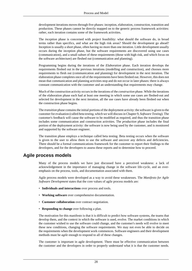
Process and Model
28
development iterations moves through five phases: inception, elaboration, construction, transition andproduction. These phases cannot be directly mapped on to the generic process framework activities:rather, each iteration contains some of the framework activities.
The inception phase is concerned with project feasibility: what should the software do, in broadterms rather than specifics, and what are the high risk areas? Should the development go ahead?Inception is usually a short phase, often having no more than one iteration. Little development usuallyoccurs during the inception phase, but the software requirements are discovered using use cases(communication), and a small subset of these requirements (those with high risk, and which focus onthe software architecture) are fleshed out (communication and planning).
Programming begins during the iterations of the Elaboration phase. Each iteration develops therequirements fleshed out in the previous iterations (modelling and construction), and chooses morerequirements to flesh out (communication and planning) for development in the next iteration. Theelaboration phase completes once all of the requirements have been fleshed out. However, this does notmean that communication and planning activities stop and do not occur in later phases: there is alwaysconstant communication with the customer and an understanding that requirements may change.
Much of the construction activity occurs in the iterations of the construction phase. While the iterationsof the elaboration phase each had at least one meeting in which some use cases are fleshed-out andselected for development in the next iteration, all the use cases have already been fleshed out whenthe construction phase begins.
The transition phase contains the initial portions of the deployment activity: the software is given to thecustomer for evaluation (called beta testing, which we will discuss in Chapter 9, Software Testing). Thecustomer's feedback will cause the software to be modified as required, and thus the transition phaseincludes some communication and construction activities. The production phase includes the finalportion of the deployment activity: the software is now being used by the customer, and is monitoredand supported by the software engineer.
The transition phase employs a technique called beta testing. Beta testing occurs when the softwareis given to the user to allow them to use the software and uncover any defects and deficiencies.There should be a formal communications framework for the customer to report their findings to thedevelopers, and for the developers to assess these reports and to determine how to proceed.
Agile process models
Many of the process models we have just discussed have a perceived weakness: a lack ofacknowledgement in the importance of managing change in the software life-cycle, and an over-emphasis on the process, tools, and documentation associated with them.
Agile process models were developed as a way to avoid these weaknesses. The Manifesto for AgileSoftware Development states that the core values of agile process models are:
• Individuals and interactions over process and tools.
• Working software over comprehensive documentation.
• Customer collaboration over contract negotiation.
• Responding to change over following a plan.
The motivation for this manifesto is that it is difficult to predict how software systems, the teams thatdevelop them, and the context in which the software is used, evolve. The market conditions in whichthe customer wished to use the software could change, and the customer's needs will evolve to meetthese new conditions, changing the software requirements. We may not even be able to decide onthe requirements when the development work commences. Software engineers and their developmentmethods must be agile enough to respond to all of these changes.
The customer is important in agile development. There must be effective communication betweenthe customer and the developers in order to properly understand what it is that the customer needs.

Process and Model
29
The customer usually also works closely with the development team, allowing the developers to morefully understand their requirements, and allowing the customer to more fully understand the state ofthe software.
Apart from stressing closer communication between customer and developer, agile models also stressbetter communication between the members of the team creating the software. The most efficient formof communication is considered to be face-to-face communication, rather than documentation.
While agile development is strongly driven by the customer, it also recognises that any plans laidout to meet their requirements may change. This generally means that agile process models use anincremental / evolutionary approach to development, delivering multiple increments of the softwareto the customer. This allows the customer to have working software, to evaluate the software, and toultimately allow the developers to more effectively respond to the customer's requirements.
Apart from not adequately dealing with change, prescriptive models also do not necessarily deal wellwith the differences between people.
For instance, people differ in the skills they have, and the levels in which they have these skills; theydiffer in how well they communicate, and in which mediums they communicate the best in (verbalor written, for example).
A process model may deal with the differences between people either with discipline (i.e., there are nooptions other than to follow the process activities as outlined by the process model) or with toleranceof these changes. While this is clearly a continuum, prescriptive process models can be characterisedas choosing discipline over tolerance, and agile models as choosing tolerance over discipline. Thereis a trade off involved in shifting from a tolerant to a disciplined process model, and vice versa: whiletolerant models are easier for developers to adapt to, and hence more easily sustainable, disciplinedmodels are apt to be more productive.
The features of agile process models
The key features of an agile process model can be summarised as follows:
• The software itself is the important measure of the team's progress, rather than documentation.
• The development team has autonomy to determine how to structure itself, handle the developmentwork, and apply the process model.
• Adaptability to change comes in large part through delivering software incrementally.
• Adaptability also comes from frequent delivery, so that customers can more easily examine thesoftware and provide feedback.
• The process is tolerant: it is adapted to the development team's needs.
• Software is important, documentation less so: this means that design and construction are oftenheavily interleaved.
Extreme programming
We will discuss the most widely used agile process model, extreme programming. Extremeprogramming is an object-oriented development approach and provides four framework activities:planning, design, coding and testing.
Planning
Planning begins by creating user stories, which are similar to use cases, which we will cover in depthin Chapter 3, Requirements Engineering. User stories relate how the software will be used, and whatfunctionality it will provide. The customer then prioritises these stories. The development team, inturn, determines the amount of development time required to develop the story.

Process and Model
30
The stories are grouped to form deliverables. These are the deliverables that will be given to thecustomer at each increment. Each deliverable is given a delivery date.
Importantly, the project velocity is determined at the end of the first increment: this is essentially thetime take to develop the number of stories that were delivered in the first increment. This can be usedto better estimate the delivery times for the remaining increments.
Note
New stories can be added at any time. The new stories are prioritised, and then added to anappropriate deliverable based on this priority.
Design
The design activity in the extreme programming process focuses around class-responsibility-collaborator (CRC) cards (see Chapter 5, Object-oriented Analysis and Design), which the developersuse to organise the classes that need to be implemented in the software. These cards are the only designdocumentation produced using this process model.
When the appropriate design is difficult to decide upon, a prototyping method is employed. The designis quickly prototyped to evaluate the risks associated with it, and to estimate the required time neededto implement the story. This prototyping is called a spike-solution.
Extreme programming encourages developers to reorganise the internal structure of the code (withoutaltering the program's behaviour) in order to make developing the software easier, and to make it lesslikely that bugs will be introduced in future work. This process of reorganisation is called refactoring.
Note
Because of the refactoring, the CRC cards often need to be modified. The design should notbe viewed as something set in stone, but as something flexible, that changes as the softwaredoes.
Coding
Extreme programming has a number of distinctive coding practices. First, before coding begins, theprocess model recommends developing unit test cases to test each of the stories being developed in thatincrement's release. The developers then code towards satisfying those unit tests. This also allows theprogrammer to better understand how the code will be used and how the code should be implemented.
The second distinctive feature is pair programming: all code is written by pairs of programmers,with one developer programming and the other ensuring that the code follows an appropriate codingstandard.
Testing
As just mentioned, unit tests are written before coding begins. It is also recommended that a frameworkis in place to run all the unit tests, allowing them to be easily and repeatedly run. This also allows forsoftware testing to occur on a daily basis.
Apart from unit tests, acceptance tests are tests defined by the customer. They focus, by their nature,on the functionality visible to the customer, and will ultimately derive themselves from the storiesused to develop the software.
Advantages and disadvantages
Extreme programming has the following advantages:
• Extreme programming is an incremental process model, and so the customer will have workingsoftware very early.

Process and Model
31
• The customer works closely with the developers, so the developers have a better understanding ofthe software requirements.
• Pair programming allows for quality checks of code as programming happens.
• Extreme programming has a strong focus on accepting changing project requirements.
Extreme programming has the following disadvantages:
• Much time might be spend re-coding the software, rather than focusing initially on a better design.
Differences in life cycle models and inconsistent use ofterminology
There are no “officially” agreed set of terms used in descriptions of software development. Likewise,there is no standard set of stages in the waterfall-model (and many other models). When reading textsfrom difference sources, and when speaking with information systems professionals, it is wise to bearin mind the meanings of the terms being used, and if necessary clarify how the terms are being used.
Such differences are not a bad thing — they are a result of both the relatively small time thatinformation systems and software development has been studied for, and reflect the dynamicviewpoints and interpretations of what we have learnt about software development to date.
Note
Do not take for granted that a particular book your are reading or person you are speaking tohas the exact same understanding of the waterfall model, or of a term such as, say, “systemdesign”, that you have in mind.
Avoid having a single “correct” version of a life cycle model, stage or deliverable, especiallysince the models and deliverables should be adapted to fit the needs of the development teamand project.
A useful learning activity to apply to each different reference source you use is to create a summary ofthe terms used and the model stages. As you work with different sources note the differences betweenthe sources. Your own understanding will improve as you attempt to build an inclusive and generalpicture of the stages and deliverables of different views of the software life cycle.
Computer Aided Software Engineering: CASE
The role of tools in engineering systems development
Each activity in a process model has tasks to be performed and deliverables to be produced. Varioussoftware tools have been developed to support software developers using a particular process model.These tools support project management and monitoring and the use of any special techniques requiredby a particular process model, such as the UML. CASE (Computer-Aided Software Engineering) toolscan also support the integration of several different deliverables to provide a consistent, overall modelof the system being developed. Such a tool facility is usually said to be performing consistency orintegrity maintenance and checking. Although there are simple, single-technique tools (such as for theUML), sophisticated tools exist to provide integrated support for many parts of a process model.
CASE tools
There are a wide range of software tools being used to support information system development. Someexamples include:
• programming language compilers and debuggers
• project planning and costing applications

Process and Model
32
• help-file author applications
• version control support systems
• program code generators and “intelligent” program editors
• fully integrated suites supporting construction and consistency checking between multiplemodelling techniques
The most sophisticated of CASE tools is the last in the list — the fully integrated tools supportingmultiple modelling techniques. Some authors argue that any software application that helps in thesystem development process is a CASE tool, including:
• word processors
• spreadsheets
• general purpose drawing and painting applications.
We shall define a CASE tool as follows: a CASE tool is a software application (or integrated suiteof application) whose sole purpose is to support one or more aspects of the software developmentprocess. The inputs and outputs of a CASE tool are either final system components, or artifacts whosepurpose in some way supports system development and management.
The above definition excludes general purpose applications such as word processors and drawingpackages.
It used to be common to make a distinction between three classes of CASE tool:
• Upper-CASE
• Lower-CASE
• I-CASE
Upper-CASE
“Upper-CASE” refers to CASE tools that support the early, abstract, “higher-level” activities of thesystem development process activities such as requirements elicitation, system analysis, creatinglogical design models, and so on. Activities which actually involve detailed “lower-level” design andimplementation issues such as coding and testing are covered by “Lower-CASE” tools.
Example of Upper-CASE tools are the SELECT-Enterprise CASE tool, and ArgoUML. They aresophisticated tools, supporting activities such as logical data modelling and data flow processmodelling techniques.
The following screen shows the Entity-Relationship Diagram window of SELECT-Enterprise:
Figure 2.7. SELECT-Enterprise screenshot

Process and Model
33
These notes will, however, mostly be making use of UML CASE tools, such as ArgoUML andUmbrello.
Lower-CASE
Activities which involve “lower-level” design and implementation issues are known as “Lower-CASE”. Examples of Lower-CASE tools are program code compilers and debuggers, interfacebuilding programs and so on.
The following is a screen shot from a Lower-CASE tool — Symantec's VisualCafe environment forJava software development. In this screen we can see some Java program code and the correspondinginterface objects on screen:
Figure 2.8. Java code
The following screenshot is another example of Lower-CASE — the command-line based javainterpreter provided by the Oracle Corporation (previously owned by Sun Microsystems):
Figure 2.9. A command-line Java interpreter
I-CASE
The “I” in I-CASE stands for “Integrated”. The most powerful CASE tools offer functions to integratea range of different kinds of models for a system, to manage a more complete picture of a system. Suchintegrated tools can check multiple models for consistency, in addition to assisting system modellersto handle the “cascade” of changes that occur when a change in one model requires a related changein another.

Process and Model
34
Each I-CASE tool tends to be developed to support a particular process model. Those CASE tools thatdo not provide integration between multiple models or products may be used for many process models— for example, regardless of the model, at some point a code compiler (or interpreter) will be needed.
IPSE — integrated project support environment
Integrated Project Support Environments are integrated applications to support project management.These usually provide some combination of project planning/scheduling, costing, version control ofmodels and software components, and support for project management documentation and reporting.
Critique of CASE
Advantages of CASE
CASE offers a number of advantages for the development of systems:
• CASE tools allow for the faster development of models, and provide support for creating diagrams.
• Some CASE tools offer simulation of the system being modelled (e.g., given an event, possiblesystem responses can be traced).
• CASE tools can be used to maintain a central, system dictionary, from which all models draw theircomponents.
• CASE tools can help the team be more positive about improving models when errors orinconsistencies are identified.
• CASE tools provide consistency checking between different types of model.
• CASE tools can provide notation and documentation standards in and between projects.
• CASE tools provide navigation support between related parts of models and diagrams.
• They provide automated documentation and report generation from the system models and maindictionary.
• IPSE CASE tools increase the rigour of project planning and management, and supportstraightforward re-planning and response to unexpected events.
Disadvantages of CASE
Although there are clearly many advantages, there are a number of potential problems with CASE:
• They can be very expensive.
• Project staff require expertise (or training) on the software.
• A particular CASE tool based around a single methodology will force a project to commit morestrongly to the methodology than they might wish to have done.
• There is a danger that high quality models and diagrams can lead to poor software development— the models may look impressive, but it is the quality of the system and not the diagrams that isfundamentally important.
Remember that having consistent models of the software does not guarantee that the software willmeet the user requirements.
Conclusion
It would be a poor project management these days not to take advantage of one or more CASE toolsfor all but the very smallest of system development projects. Software support for the activities and

Process and Model
35
production of deliverables during system development has progressed with the profession's increasedunderstanding and modelling of the system development process.
Some I-CASE tools provide support for a wide range of high- and low- level products of the lifecycle, thus blurring the distinction between Upper- and Lower- CASE — such products can work fromabstract models such as those produced by the UML, and provide skeletal databases and computerprograms.
Review
Questions
Review Question 1
What is a life cycle model?
A discussion of this question can be found at the end of this chapter.
Review Question 2
What are the activities of the generic software process?
A discussion of this question can be found at the end of this chapter.
Review Question 3
What features of the waterfall life cycle model separate it from other models?
A discussion of this question can be found at the end of this chapter.
Review Question 4
Describe the disadvantages of the waterfall model.
Answer to this question can be found at the end of this chapter.
Review Question 5
What are the main features of the prototyping life cycle model?
A discussion of this question can be found at the end of this chapter.
Review Question 6
What are the points of the Agile Manifesto?
A discussion of this question can be found at the end of this chapter.
Review Question 7
What is a CASE tool? Provide some examples of CASE tools. Try to also provide examples of toolsthat you may have used before.
A discussion of this question can be found at the end of this chapter.
Review Question 8
Describe some of the advantages of CASE?

Process and Model
36
A discussion of this question can be found at the end of this chapter.
Answers
Discussion of Review Question 1
A life cycle model, or software process model, is a description of the best practices for engineeringand developing software. It is usually broken down into stages, describing the deliverables producedduring each stage, and describing the order or iterative cycles of the stages, and when each stage wouldbe appropriate to perform.
Discussion of Review Question 2
There are five generic activities:
• Communication
• Planning
• Modeling
• Construction
• Deployment
Discussion of Review Question 3
The waterfall model breaks the system development process into a linear sequence of stages, eachinvolving a specific activity. Each stage produces deliverables that become the inputs to the followingstage. Once a stage has been completed it cannot be revisited — so decisions made in early stage arecommitted to and determine what happens at later stages.
Discussion of Review Question 4
The Waterfall model assumes that there is a full understanding and specification of the requirementsat the beginning of the project, and that these requirements will not change during development.Since the deliverables at each stage is usually not software, it is easy for none-software relateddeliverables — and the bureaucracy surrounding these deliverables — to become the focus of thesoftware development. Because of the linear nature of the model, problems identified in earlier stagesbecome progressively more difficult and expensive to fix in later stages.
Discussion of Review Question 5
The prototyping model attempts to produce a small version of the final system that has only some ofthe final software's functionality. Prototype life cycle models allow for the developers and users toexplore the uncertain requirements of the software system, and an analysis of the prototype can formthe basis of a requirements specification for further development. Because prototypes are generatedquickly and are incomplete, once the requirements are better understand the prototype is discardedand development restarted using another process model.
Discussion of Review Question 6
There are four points:
• Individuals and interactions over process and tools.
• Working software over comprehensive documentation.
• Customer collaboration over contract negotiation.

Process and Model
37
• Responding to change over following a plan.
Discussion of Review Question 7
CASE tools are software whose sole purpose is to support one or more aspects of softwaredevelopment.
Common examples include compilers and debuggers — if you are using Ubuntu or OS X, thatwill often be GCC for the compiler, and GDB for the debugger. There are also many CASE toolsfor planning and software costing, such as Microsoft Project. Other case tools include those forauthoring help files, version control systems (such as Subversion, Bazaar, Mercurial and Git), codegenerators and program editors (such as Emacs, Visual Studio and XCode), and tools providing accessto modelling techniques such as the UML (for example, ArgoUML).
Discussion of Review Question 8
Case tools allow for the faster development of various software models, and can sometimes evensimulate portions of the software from these models. Some tools allow a central dictionary to bemaintained where each model can take their components from. They can automatically check forconsistency between various models, can provide a standard for notation and documentation, andcan provide easy navigation between different portions of the models. They can support planning theactivities of the software development life cycle, and can support the programmers directly with theirdevelopment (by providing access to documentation, report generation, by keeping track of changesmade to the source code, and so on).

38
Chapter 3. Requirements EngineeringObjectives
At the end of this chapter you should be able to:
• Explain the need for requirements engineering.
• Give a series of steps for use in performing requirements engineering.
• Create and interpret use case models.
Requirements engineeringThe first two activities in the generic process framework is that of communication and modelling.A large portion of these activities are concerned with discovering the requirements of the softwarewhich the customer is asking to have developed. This chapter deals with this process of requirementsengineering.
Note
As with all other activities in a process model, requirements engineering should be tailoredto fit the developers creating the software, the product being created, and the overall processmodel being employed. In the previous chapter you could already see this happening withthe extreme programming software process model, which limits modelling to the creation ofCRC cards (see Chapter 5, Object-oriented Analysis and Design).
Requirements engineering is concerned with understanding the software system that the customer hasrequested. It provides the base on which software design and programming can proceed. Importantly,if the developers do not adequately understand the requirements, it is very likely that the software willnot meet the customer's needs. This makes understanding the customer's requirements important tothe success of the development project.
What is requirements engineering?At its most essential, requirements engineering is focused on discovering what it is that should bedeveloped (and not how it should be developed). There are a number of aspects to this:
• What does the customer want?
• What does the user require in order to use the system?
• What will the software's impact on the users be?
To discover this information, requirements engineering contains a number of overlapping steps:
1. Inception, in which the nature and scope of the system is defined.
2. Elicitation, in which the requirements for the software are initially gathered.
3. Elaboration, in which the gathered requirements are refined.
4. Negotiation, in which the priorities of each requirement is determined, the essential requirementsare noted, and, importantly, conflicts between the requirements are resolved.
5. Specification, in which the requirements are gathered into a single product, being the result of therequirements engineering.

Requirements Engineering
39
6. Validation, in which the quality of the requirements (i.e., are they unambiguous, consistent,complete, etc.), and the developer's interpretation of them, are assessed.
7. Management, in which the changes that the requirements must undergo during the project'slifetime are managed.
Requirements engineering will usually result in one or more work products being produced. Theseproducts, taken together, represent the software's specification (see the specification step previouslymentioned, and detailed below). These work products, however, do not have to be formal, writtendocuments — indeed, the work products can be a set of models, a formal mathematical specification,a collection of use cases or user stories, or even a software prototype.
Note
These steps are overlapping for a variety of reasons. You should be able to notice that someof them, such as management, must occur throughout the communication and modellingactivities. Negotiation will also occur at each of the various requirements engineeringsteps. More importantly, a process model which understands that requirements may be(initially) poorly understood, and that they may change through the project's lifetime, willalso iteratively collect and detail the use cases (consider the unified process model from theprevious chapter). This iterative process will forcefully overlap all of these steps.
The steps in detail
InceptionThe requirements engineering process begins by examining the problem which the software shouldsolve and gaining an understanding of both the problem's nature and the nature of the desired solution.This should be done in a context-free manner, that is, a manner which does not presume to knowanything concerning the problem, the customers, the users, and the requested solution. The followingquestions may be asked:
• Who is requesting the software?
• Who will use the software?
• What is the benefit that the software will bring?
It is important to identify the stakeholders in the project. Stakeholders are the people who will findbenefit in the project and the software being developed. They may include:
• Customers
• End users
• Business operations managers
• Product managers
• Advertising and marketing staff
• Software engineers
• Support engineers
Each of the stakeholders will have a different view on what the software product should do and onwhat the software engineers should focus on. This might be on creating “sexy” features (from themarketing department), staying within budgets and deadlines (from managers), maintainability (from

Requirements Engineering
40
support engineers) and so on. Out of these views, the requirements engineer should determine whichrequirements there are a consensus on, and on which requirements the stakeholders disagree. Resolvingdisagreements between stakeholders makes up the negotiation step.
Something to consider during inception is the effectiveness of the communication between therequirements engineer and the customers. This may be done by, for example, asking the customer ifthey feel that they have been asked appropriate questions concerning their problems, and if the personcommunicating with the requirements engineer feels that they are (or are not) the person who shouldbe answering the engineer's questions.
ElicitationThis step is concerned with identifying the overall problem the software is attempting to solve,proposing solutions, negotiating between the differing approaches to solving the problem, and finallyspecifying a basic set of requirements.
This can be done by calling a meeting between all of the stakeholders. It is important to nominatesomeone to act as a facilitator, who will guide the meeting. Each of the attendees should bring to themeeting a list of:
• objects that make up the system's operating environment
• objects used by the system (such as those things which make up the input to the system)
• objects produced by the system
• the services that interact with these objects
• various constraints, such as time and budget constraints, interoperability constraints, performancerestraints, usability constraints, and so on.
ElaborationThis step involves expanding on the requirements defined in the previous two steps, and from theserequirements producing an analysis model, which is a technical model of the software and its functions.
The construction of analysis models will be discussed in detail in the following two chapters.
NegotiationThis step involves negotiating between the various stakeholders in order to remove any conflict inthe requirements. A useful technique for resolving these conflicting requirements is to provide eachof the stakeholders with a finite number of priority points. They may then allocate points betweenthe conflicting requirements as they see fit. The overall importance of any requirement can then bedetermined by the number of priority points that it has received.
SpecificationThe specification step produces the final product of the requirements engineering process. It describesthe software, both its functions and constraints. The specification need not be a written document,but could also be a graphical model (such as those produced using the UML), software prototype orformal model, or a collection of these.
ValidationThis step is concerned with ensuring that the gathered requirements in the software specificationmeet certain standards of quality. For example, have the requirements been written to the proper

Requirements Engineering
41
level of abstraction, or do they provide too much technical detail for the given stage of development?Is the requirement necessary, or something not essential to the software? Are the requirementsunambiguous? Do requirements contradict other requirements?
A useful action during validation is to ensure that each requirement has a source attributed to it. In thisway, if more information is required, the requirements engineers know who to contact.
ManagementRequirements change over time; requirements management is concerned with controlling and trackingchange in the requirements.
Requirements management proceeds by associating requirements with various aspects of the softwareengineering process. As these aspects are changed, the requirements associated with them can be easilyidentified and changed. As these requirements are changed, all aspects of development associatedwith the modified requirements can be examined, and in this way the changes can more easily bepropagated through the project.
Such an association between requirements and aspects of the project can be done using a table: eachrow in the table represents a specific requirement, each column an aspect of the software project. Theentries mark whether a requirement is associated with that aspect.
Use case modelingUse case modelling is a useful tool for requirements elicitation. It provides a graphical representationof the software system's requirements.
The key elements in a use case model are actors (external entities), and the use cases themselves. Inoutline, a use case is a unit of functionality (a requirement), or a service, in the system. A use caseis not a process, or program, or function.
Because use case models are simple both in concept and appearance, it is relatively easy to discuss thecorrectness of a use case model with a non-technical person (such as a customer).
Use case modeling effectively became a practicable analysis technique with the publication of IvarJacobson's (1991) book “Object-oriented software engineering: a use case driven approach”. Jacobsonhas continued to promote this approach to system analysis to the present day, and it has now beenformalised as part of the UML. However, use case modeling is not very different in its purpose andstrategy from earlier techniques, such as structured viewpoint analysis.
Use case modeling in the UML specificationThe Unified Modeling Language (UML) represents a deliberate attempt to standardise the modelingnotation used in software engineering, particularly object-oriented development. The widespreaduptake of the UML is a result largely of two factors. First, it is driven by some of the most influentialproponents of object-oriented development, including James Rumbaugh, Grady Booch, and IvarJacobson. Second, it has broad support from major business concerns in the software industry,including Microsoft, IBM, Hewlett-Packard and Oracle.
The notation specified for use case modeling by the UML is not very different from that originallyproposed by Jacobson, so early books and articles on use case modeling that follow the Jacobsonstrategy are still useful reading.
It is only fair to point out that not all experts support the UML effort, and it comes under regular andharsh criticism, some of it fair. For example, one criticism is that there is not good enough integrationbetween the different components of the UML (e.g., between use case and class modeling). No doubtthis will improve in time. In due course you will be able to make your own judgement on this issue, but

Requirements Engineering
42
is important to keep sight of the fact that the UML is an international standard for software modeling,and any software professional needs to understand it.
The UML is under continuous development, and at the time of writing the latest version is 2.2. Thedefinitive reference for the UML notation is the UML specification, which is available from theObject Management Group's Web site [http://www.omg.org/technology/documents/formal/uml.htm].However, while this is an authoritative document about the UML, it is not a good document fromwhich to learn about the UML.
It is important to understand that the UML is a specification for a modeling language. It is mostemphatically not a software design methodology. Although the UML states the symbols that are to beused in use case modeling, and how they are to be interpreted, it does not say when, or even if, usecase modeling should be applied. We shall have more to say about this later.
Use case modeling symbols
This section presents an overview of the symbols used in use case modeling; the important ones willall be discussed in detail later.
Symbol Name Interpretation
Nam eor
«act or»Nam e
Actor An entity (human or otherwise)external to the system, and whichinteracts with it
Nam e
or«use-case»
Nam e
Use case A service or unit of functionality
Nam eSystem boundary Indicates the division between
the system being designed andthe rest of the world
A Use Case
An Actor
Nam e
Communication association The line indicates that aparticular use case is associatedwith a particular actor. The nameis optional and often omitted.An arrow can also optionally beused; where present it does notindicate a flow of information(such as in a data flow diagram)
A Use CaseNam e
Another Use CaseUse case association Indicates that to use cases are
related in a particular way, e.g.,

Requirements Engineering
43
Symbol Name Interpretation
the one use case's behaviourincludes the behaviour ofanother use case
«name» Stereotype Indicates that the symbol itis attached to belongs to aparticular category
A Use Case Another Use CaseNam e
«nam e» Generalisation Indicates that the two symbolsit connects are related bya generalisation-specialisationrelationship. For example, oneactor is a sub-type of another, orone use case is a type of another.Both the name and the stereotypeare option
ANote
Note The designer may, and should,qualify any part of the modelwith a textual note if it improvesthe clarity of the design
Note
The above images were created using the Umbrello Software package [http://uml.sourceforge.net].
Actors
An actor is any entity, human or otherwise, that is external to the system being designed. Two symbolsare available in the UML specification:
Figure 3.1. Actor representations
Nam eAn actor can be represented by a stick figure.
«act or»Nam e
Alternatively, an actor may be represented by a class with the «actor» stereotype.
The “stick figure” symbol is the more expressive, but can lead to confusion if the actor is not in facta human but a machine. The rectangle symbol is the standard UML symbol for a class. What thissymbol says is that the entity is a class that is a member of the category “use case”. The reason whyan actor is a type of class will be discussed later. Because of its greater expressive power (that is, anability to make a more immediate impression on the viewer) it is probably best to use the stick personfigure where possible.
Since use cases are technically classes, and by convention class names start with a capital letter, namesof use cases should also begin with a capital letter. The UML specification does not insist on this, butit is common practice.
Two interesting philosophical issues are associated with actors. First, should the actor be a person,or the part of the computer with which they interact? For example would we ever want an actorcalled “Keyboard” or “Printer”? In designing a word processor, for instance, there is only one human

Requirements Engineering
44
user and they fulfil all the roles within the system. But you may wish to distinguish between, saykeyboard, mouse, and printer actions. However, distinguishing between different pieces of hardwareis probably inappropriate at this level, and it could be argued anyway that use case modelling is not ahelpful way to begin the design of a word processor. On the other hand, a supermarket stock controlsystem may accept input from a bar-code scanner at the checkout, when the cashier registers the pricesof the customer's purchases. Is the actor here the cashier, or the bar-code scanner? Perhaps neitheris appropriate, as the cashier can probably enter the identities of products manually if the bar-codescanner does not work. Do we want to distinguish between different techniques for entering itemdetails at the highest level of analysis? Probably not. In this case we could perhaps invent a moreabstract actor (called, perhaps, “point-of-sale”) that provides the key message: that something at thepoint-of-sale interacts with the system whenever a purchase is made. In summary, then, when a humanbeing interacts with a computer system, it is not necessarily the case that the human is identified asthe actor. It is often clearer to use a non-specific entity as the actor.
The second philosophical issue is concerned with whether an actor has to be an active participant inan interaction. For example, in a computer-based building security system, do we want “Burglar” asan actor? A burglar does not actively interact with the system; indeed they would probably rather notinteract with it at all. Moreover, a burglar may interact with the system in a number of different ways,all passively. In this case, it may well be better to identify the sensor devices as actors. What aboutthe fire alarm? Presumably “Fire Detector” is a better actor than “Fire”?
The UML gives us no guidance on these issues; although the letter of the UML specification is thatactors can be any external entity, the spirit of the standard seems to be that actors are people whointeract with the system in a rich, complex way. There is little concern for “trivial” actors like printersand fire detectors.
These complications notwithstanding, actors do not have to be human beings; they may be externalcomputer systems. For example, we may be designing a system for allocating staff work timetablesthat draws information from a central record of employees which is part of the payroll system. In thiscase, “Payroll System” would be an actor.
You should bear in mind that you will never implement an actor; by definition an actor is external toyour system. You will, however, implement the interfaces used by actors to interact with the system.
Actors as roles
A decision that the use case modeller has to make is whether to treat (human) actors as expressions ofa person, or as expressions of a role within an organisation. Perhaps an example will help to clarifythis issue. Suppose that you are designing a computer system to automate the operations of a largelibrary. The system should maintain the library catalogue, provide information to staff and readers,check books in and out, provide guidance on re-shelving returned books, manage inter-library loans,warn users about overdue books, and manage collection of fines and subscriptions.
Most people faced with this problem begin by considering the types of people who will use the system.Two such groups come to mind immediately: library users and library staff. In a library one will oftenfind that staff members have very general job descriptions, and will take a hand in most of the normaloperations of the library. We will refer to these people as “librarians”. So far our use case modelhas two actors: Librarian and User, and these two actors interact with all the use cases that we couldidentify. In this case we are treating “Librarian” as an expression of a person. We could get a lot ofinformation about what services the computer system should provide by reading the job descriptionof a librarian.
The problem with this approach is that it has no high-level structure, and is therefore not veryexpressive. We could convey much the same information as the use case model by merely writing a listof library services. There is no scope for simplification and management of the model by generalisation(see later). Furthermore, it carries the implication that librarians are interchangeable, and any librariancan do the work of any other. Even if this is true at the time the system is designed, it may not continueto be true. For example, more junior staff members may not have authority within the system to order

Requirements Engineering
45
new books for the library. A person managing the stock of books is interacting with the system in atotally different way to the person who is, for example, signing up new library users. The fact thatthese to job functions may perhaps be carried out by the same physical human being is irrelevant; theyare totally different roles within the system, and should be considered to be different actors.
Of course, we could now go to the opposite extreme and create a new actor for every service the systemprovides, but this leap from the frying pan into the fire would still result in a model with no structurethat is difficult to simplify. In addition, there may be a loss of expressiveness. For example, in thelibrary system it is quite likely that both staff and users can browse the catalogue of books. They willquite possibly do this in an identical way, and see exactly the same information. Moreover, this activityis completely separate from any other functionality the system may provide. So we may be tempted tocreate a new actor (perhaps called “Catalogue Browser”) to model this role within the system. But wewill have lost a very important piece of information by doing this: the fact that both staff and users canbrowse the catalogue implies that we have to put computer terminals or workstations on both sidesof the counter, so to speak.
So what is the correct approach? In short it is the one which leads to the simplest correct model whichis still adequately expressive. Of course it is more important that the model is correct than that it issimple. To arrive at this point may require that your choice of actors be modified several times duringthe course of construction of the use case model.
Identifying actors
In the last section we considered the distinction between actors as people and actors as roles, andclearly this is an issue that needs to be taken seriously by the requirements engineer. However, it onlybecomes an issue when we know enough about the way the system is to be used to have a potential setof actors to hand. We now have to consider the situation where the analyst knows nothing at all aboutthe system to be developed, and doesn't have the first idea what the actors are. Many developmentjobs begin like this.
The analyst's first recourse is to the stakeholders identified through the earlier requirementsengineering steps. The stakeholders should certainly be on the initial list of actors.
You may then ask what information is to be manipulated by the system, and where that informationwill come from. All information that is not present in the system at the instant it begins work will becoming from an actor of some sort. If there is not enough information to do this, then this is a signthat further information must be elicited from the customers.
Other potential actors include all the computer systems with which the system will interact, and anyother hardware devices (including hardware such as printers, bar-code readers, and so on).
There are also various “standard actors” that all systems of any complexity are going to need, andwhich may not have been considered by the clients. These include the person (or rather the role) whichmaintains the system after it has been put into service, the person who performs software upgradesand tests, the person who carries out and checks backups (if not automatic), and so on.
When developing a software system to replace a manual procedure, or an older software system, actorsmay be identified by watching people go about their daily work, and by speaking to people who areexperts on the business the system has to carry out.
It is probably not possible to identify actors without some consideration of the services that the systemprovides. In practice design work will switch between consideration of the actors and considerationof the use cases.
Individual actors and classes of actors
All of the forgoing was, we hope, largely common sense. Now it is time discuss a technicality. Wewill state the principle, and then go on to explain it.

Requirements Engineering
46
The principle is this: the UML specifies that an actor in a use case is a class, and individuals areinstances of that class.
The actors in a use case model do not represent individuals (individual humans or individualcomputers), but classes of individuals. For example, an actor called “Customer” models all thoseproperties that customers have in common; it is, in effect, the class of all customers. It will be assumedby anybody who reads your model that the ways in which the Customer actor interacts with yoursystem will apply to all customers. So if some customer or group of customers is expected to behavedifferently, then we need a different actor to handle this case.
This may seem trivially obvious, but the complication is that the above principle is true even if thereis only one instance of an actor. For example, a company may have only one managing director, andmay be constrained by law only to have one, but if the managing director interacts with the system youare designing in a specific way, then they are a class, not an individual. The problem is that althoughthe designer understands intellectually that actors are classes, they may still have a specific individualin mind, leading to a bad model. The reason is this: suppose Joe Bloggs is a bank clerk; there can bedifferent types of bank clerk, but it is meaningless to talk of different types of Joe Bloggs. And theability to simplify a model by identifying where one thing is a type of another thing is a key featureof use case modeling, and indeed of all types of object-oriented design.
System boundary
The system boundary demarcates the system being designed from the rest of the world. It is denotedsimply by a box with the name of the system in the corner.
Figure 3.2. The system boundary
Nam e
Use cases are inside the box, actors are outside. Because different symbols appear inside the box andoutside, in practice it is usually unnecessary to show the system boundary explicitly. One circumstancein which it is necessary to show it is if you wish to show the use case models of two or more differentsystems on the same diagram. This may be necessary if you are designing a system which interactswith another in a way that is too complex for you to show the external system as simply an actor.
Some modeling software will draw the system boundary automatically.
In the design of a large, complex system, it is said that the boundary may “move” during the designoperation. In fact what is happening is that decisions are being made about what functionality is theresponsibility of the current design exercise, and what is not. For example, it may turn out that duringthe analysis of a staff payroll system, management of staff health records — which was previouslythe responsibility of another system — is seen to be more appropriately part of the payroll system. Ineffect, the system boundary has “moved” to encompass part of another system. Needless to say, suchmovement needs to be settled as early in the development process as possible.
Use cases
In the UML, a use case can be represented in two different ways:

Requirements Engineering
47
Figure 3.3. Representations of use cases
Nam e
Use cases may be represented by a title within an ellipse.«use-case»
Nam e
Use cases may be represented by a class with the «use case» stereotype.
Most designers will immediately recognise the oval as a use case (the oval symbol has no othermeaning in the UML) so this symbol is to be preferred where available. The other symbol reflects thefact use cases are technically classes (just as actors are), whose category is “use case”. We will discusslater what is meant by a class of use cases.
Although use cases are central to use case modeling — and indeed to many object-orienteddevelopment strategies — there is surprisingly little general agreement on what a use case is. In fact,there are people currently working on doctoral theses whose subject is what a use case is supposed tobe showing. The following definition is taken from version 0.8 of the UML specification:
A use case is a generic description of an entire transaction involving several objects.—UML 0.8
This rather terse definition was all the UML had to say about the nature of use cases at that point. Inversion 1.3, there is the following, somewhat expanded, definition:
The purpose of a use case is to define a piece of behaviour of an entity withoutrevealing the internal structure of the entity. The entity specified in this way may be asystem or any model element that contains behaviour, like a subsystem or a class, ina model of a system. Each use case specifies a service the entity provides to its users,i.e. a specific way of using the entity. The service, which is initiated by a user, is acomplete sequence. This implies that after its performance the entity will in generalbe in a state in which the sequence can be initiated again. A use case describes theinteractions between the users and the entity as well as the responses performedby the entity, as these responses are perceived from the outside of the entity . Ause case also includes possible variants of this sequence, e.g. alternative sequences,exceptional behaviour, error handling etc. The complete set of use cases specifiesall different ways to use the entity, i.e. all behaviour of the entity is expressed byits use cases.
—UML 1.3
Versions 2.2 states:
A use case is the specification of a set of actions performed by a system, whichyields an observable result that is, typically, of value for one or more actors or otherstakeholders of the system.
—UML 2.2
In fact, these are very general descriptions, and not particularly helpful to the practitioner; here aresome more pragmatic views of the use case.
Use cases as services
In this view, each use case provides a particular service to the users of the system. Examples of servicesmay include withdrawing money from an account, printing a report, reserving a theatre ticket, andordering a book. Every time an actor interacts with a use case a transaction occurs; this transactiontakes time and may have a number of alternative paths.

Requirements Engineering
48
Use cases as business processes
This view of use cases seems to be favoured by people with an interest in business process modeling.In this view, a use case is an activity of the business, such as ordering stock, issuing a check to clear anaccount, or checking a customer's credit-worthiness. Superficially this view is not that different fromthe view of use cases as services, but the implication here is that use cases are best characterised by adiscrete series of actions, perhaps illustrated by a flowchart (the UML equivalent of a flowchart is anactivity diagram; expanding use cases into activity diagrams is quite common practice).
Use cases as increments of functionality
In this view, adding a use case to the system is equivalent to adding some extra functionality, with theproviso that the new functionality be largely self-contained.
These views are not mutually exclusive, and all are compatible with the UML definition. However,the view that the designer adopts will subtly influence the character of the model produced.
Whichever view of you take of use cases, it is important to remember that a use case is a thing, notan event or a process. It is not uncommon for novices to generate use cases with names like “print” or“mouse moved”. “Print” is a process or action. It may be a valid use case, if you mean by “print”, “thefacility to allow a user to obtain a printed output”. Some experts recommend that you force the namesof use cases to be nouns to reinforce this meaning. In this case “Print Service” or “Print Facility” mightbe better names. “moused moved” is an event, a thing that happens to the system.
Relationships between use cases
It is possible, and usual, to show that one use case is related to another. The standard notation for thisis a dashed line:
Figure 3.4. Use case association
A Use CaseNam e
Another Use Case
An association between use cases is typically shown with a dotted line.
A stereotype can also, optionally, be given to the relationship. This indicates the type of relationship,of which the most important are «include» and «extend». An example of an «include» relationshipis show below.
Figure 3.5. Use of stereotypes in use case relationships
Ordering Service
Credit Ordering Service
«include»
In this example, “Credit Ordering Service” includes “Ordering Service”, that is, all the behaviour of“Ordering Service” will be invoked whenever “Credit Ordering Service” is invoked. This is sensibleif ordering something on credit is the same as ordering something with payment, plus a bit extra.

Requirements Engineering
49
Typography
Stereotypes in the UML are enclosed in guillemets: « and ». Often, if the typist or applicationis unable to represent these symbols, << and >> (two less-than or greater-than signs) areused instead. However, now that Unicode display is available on most operating systems, theguillemets are to be preferred. The Unicode code points for « is u+00AB, and » is u+00BB.Your operating system will no doubt have an easier input method available to you thanentering Unicode code points directly.
In the UML, «extend» is similar to «include», with the distinction that with «extend» the behaviourof the extending use case will not always be invoked.
A note on terminology and semantics
The UML uses the term «extend» here because Jacobson used this term in his earlierwork on use case modeling. Unfortunately, many authors use the term “extend” to mean ageneralisation relationship — in other words, that one thing is a type of another thing. This isparticularly relevant in Java programming, where the word “extend” has this (generalisation)sense, and not the sense defined in the UML. To further complicate matters, the «include»relationship does denote a kind of generalisation: a “credit ordering service” is a type of“ordering service”. These complications have little impact on use case modeling or onprogramming in practice, but they do cause confusion among students (and others), and itis good to be aware of them.
Describing and specifying use cases
A use case diagram on its own may well be a useful method for describing the large-scale structure of asystem; however, it is of very limited use as the input to a more detailed design operation. In practice itis necessary to describe use cases in a more detailed fashion if the model is to be interpreted properly.
Such a description is not only an aid to communication, it is an aid to validation. Validation is theprocess of ensuring that a specification is correct, in contrast to verification, which is the process ofensuring the product meets its specification (see Chapter 9, Software Testing). If the analyst cannotdescribe a use case in a way that makes sense to someone else, then one of two things has happened:
• The analyst has made an error: the use case is not valid and should be removed and its functionalityplaced elsewhere;
• The analyst has insufficient information about the system being developed.
Either case needs to be corrected.
How do we describe use cases? Two approaches are in widespread use.
• Plain text. This is the approach recommended by the UML specification. Normally a few paragraphsof text should be adequate. Most experts recommend that the text used should be in language termswhich the customer uses; that is, a system for controlling a steel mill should be written in thelanguage of a steel producer, not a software engineer, even though the latter may allow greatertechnical accuracy. The reason for this is simple: only the clients can confirm that the use casemodel is correct, and that they meet the requirements of their application. While the analyst can besure that the model is logically consistent, and can be implemented, this is not good enough groundsfor proceeding with development.
• Using a sub-model. By this we mean using a further, more detailed model, to clarify the use case.Ultimately, as we shall see, a use case will be expanded into a collaboration diagram, that is, aninteracting group of classes. However, this does not describe the use case in the sense meant above;this will probably not help customers to determine whether the model represents a system that meetstheir needs. A common choice of a sub-model is the activity diagram. This diagram is a relative

Requirements Engineering
50
newcomer to the UML, and is not very different from a traditional flowchart. It shows the sequenceof steps that are carried out when a use case/actor transaction occurs, and can show alternativesequences of operations which are selected according to some condition of the system. The use ofactivity diagrams is beyond the scope of this chapter, but should be explained in any UML textbookand, of course, in the UML specification.
Individual use cases and use case classes
Use cases are technically classes. Thus a use case does not represent a particular delivery of a service,or use of some functionality, but all conceivable deliveries of the service.
If a use case is a class, then the individuals / instances are the specific cases of a transaction occurringbetween the use case and one or more actors.
If all interactions between the actor(s) and the use case are identical, then the distinction between theuse case class and its individual instances is not important to the analyst. It becomes important whena use case can behave in many different ways, that is, the individual instances of the use case class aredifferent. If these individuals are important enough to be documented, they are called scenarios.
For example, suppose we are developing a computer system that allows people to place credit-cardorders for our customers' products using a Web browser. We have identified a use case called “PlaceOrder”, which represents an ordering transaction between the customer and the system. This use casehas very complex behaviour, because there are many things that can go wrong while placing the order.For example, the credit card company may not authorise the funds transfer, the credit card numbermay be invalid, the connection to the credit card company may be out of service, and so on. In allcases the use case must exhibit behaviour that tries to recover from these errors. For example, if theuser enters an invalid card number, they must be given the opportunity to correct it and try again.
For the purpose of documenting the use case we may use a model like an activity diagram to showthe general behaviour, but support it by describing a number of possible complete transactions, wheredifferent errors are encountered and corrected. These descriptions are the scenarios of the use case.Including scenarios for complex use cases helps the analyst to be sure that the use case is properlyspecified, because the clients will be able to understand the scenarios (which are in plain language),and the analyst and their colleagues will be able to check that the scenarios are compatible with thegeneral pattern of behaviour specified for the use case.
The concept of generalisation
Generalisation is one of the most important concepts in use case modeling, and indeed in objectorientation in general. When stated as a principle it appears trivially obvious, but it has profoundimplications. The principle is this:
Generalisation
Entity A is a generalisation of entities B, C... if the behaviour, attributes and associations ofB, C... are found in A, and no properties of A are absent from B, C...
We say that entities B, C, and so on, inherit the properties of A. This can also be stated as: A is ageneralisation of B and C if B and C are types of A (we could also say sub-types or sub-classes);A is a generalisation of B and C if B and C extend the functionality of A, while retaining all of A'sfunctionality
Here is trivial example: Dog and Cat are types of Mammal, because all dogs and cats share the basicproperties of mammals (e.g., having fur, being warm-blooded, having four limbs). We may say thatMammal is a generalisation of Dog and Cat; alternatively we could say Dog and Cat are specialisationsof Mammal, or types of Mammal, or sub-classes of Mammal. Note that when we say that Mammalis a generalisation of Dog and Cat we are not saying anything about whether there are other types ofMammal; there may be, but we haven not specified any.

Requirements Engineering
51
Another example: A business wishes to automate some of its sales procedures. Preliminary interviewsreveal that there are a number of staff roles in the Sales department. A salesperson can place orders onbehalf of customers and check the status of these orders. A technical salesperson has the same duties,but additionally is able to provide customers with detailed technical advice (which we would notexpect an ordinary salesperson to be able to do). A sales supervisor is a salesperson, with the additionalresponsibility of creating new customer accounts and checking their credit-worthiness. It is reasonableto assume that Salesperson is a Generalisation of Technical Salesperson and Sales Supervisor, becausethe technical salesperson and sales supervisor have all the properties of a salesperson, and some extra.
We can construct an outline use case model to show these relationships. We will assume for the sakeof simplicity that the use cases are “Place Order”, “Check Order”, “Create Account”, “Check Credit”,and “Technical Advice”. Without generalisation, we obtain the following model:
Figure 3.6. A use case example, without generalisation
SalesSupervisor
SalesPerson
Check Credit
TechnicalSalesPerson
Technical Advice
Check Order
Create Account
Place Order
«extend»
While this is logically correct in that it accurately captures the information given in the text, the numberof associations in the diagram makes it difficult to read. It provides no more insight into the systemthan does the textual description.
In the UML, the symbol for a generalisation is an arrow:
Figure 3.7. Use case generalisation
A Use Case Another Use CaseNam e
«nam e»

Requirements Engineering
52
The arrowhead points to the more general entity. If we take account of the generalisation relationshipspresent in the “Sales” example, we reach a model like this:
Figure 3.8. Use case example, with generalisation
SalesSupervisor
SalesPerson
TechnicalSalesPerson
Check Credit
Technical Advice
Create Account
Check Order
Place Order
«extend»
This model does not have to show that “Technical Salesperson” and “Sales Supervisor” can checkorders and place orders, because this is implied by their being sub-classes (specialisations) of“Salesperson”. Not only is this model easier to read, it gives a more immediate insight into the systembeing analysed.
You will not always be able to simplify a use case model using generalisation, but you should be onthe alert for the opportunity to.
In the example above, “Salesperson” was an actor in its own right, as well as being a generalisation ofother actors. That is, we would have identified “Salesperson” as an actor with or without generalisation.Sometimes, however, it is appropriate to “invent” actors simply to stand as generalisations of otheractors, with the purpose of simplifying the model. These actors are referred to as “abstract”, becausethey abstract, or simplify, a system. An abstract actor is a special case of an abstract class. We shallhave more to say about abstract classes in the next unit.
A simple example
This is an example of a complete, simple use case diagram. It is based on the “Sales” example presentedearlier. We will start with a description of the business, then present the use case diagram and thetextual specification of the individual use cases. Note that a use case model is incomplete without thisspecification, either in plain text or something else.

Requirements Engineering
53
A use case example
A retail business wishes to automate some of its sales procedures. The retailer buys itemsin bulk from various manufacturers and re-sells them to the public at a profit. Preliminaryinterviews reveal that there are number of staff roles in the Sales department. A salespersoncan place orders on behalf of customers and check the status of these orders. A technicalsalesperson has the same duties, but additionally is able to provide customers with detailedtechnical advice (which we would not expect an ordinary salesperson to be able to do). Asales supervisor is a salesperson, with the additional responsibility of creating new customeraccounts and checking their credit-worthiness. A dispatcher is responsible for collecting thegoods ordered from the warehouse and packing them for dispatch to the customer. To assistin this operation, the computer system should be able to produce a list of unpacked ordersas well as delete the orders from the list that the dispatcher has packed. All staff are ableto find general details of the products stocked, including stock levels and locations in thewarehouse. A re-ordering clerk is responsible for finding out which products are out of stockin the warehouse, and placing orders for these products from the manufacturers. If theseproducts are required to satisfy an outstanding order, they are considered to be “priority”products, and are ordered first. The system should be able to advise the re-order clerk ofwhich products are “priority” products. A stock clerk is responsible for placing items thatarrive from manufacturers in their correct places in the warehouse. To do this the clerk needsto be able to find the correct warehouse location for each product from the computer system.Currently, the same person in the business plays the roles of stock clerks and re-order clerk.
Figure 3.9, “A full example”, shows the associated use case diagram.
Figure 3.9. A full example
StaffMem ber
StockClerkDispatcher
Check Stock
ReOrderClerk SalesPerson
Despatch Service
SalesSupervisor
Priority Reordering
TechnicalSalesPerson
Check Credit
Technical Advice
Check Order
«include»
Create Account
«include»
Place Order
«extend»
Brief use case specifications
• Check Stock: Allows a user to check the levels of stock of any item held in the warehouse,and where that item is shelved. A particularly important scenario is that of obtaining a lista stock items for which the stock level is zero, that is, of which there is no stock in thewarehouse.
• Place Order: A salesperson places an order on behalf of a client. This has the effect ofmaking information about the order available to Dispatch Service. The order remains onthe system until it has been packed and dispatched.

Requirements Engineering
54
• Dispatch Service: Allows a list of outstanding orders to be obtained, and updated whenorders are packed. An order is not available to this service if it cannot be satisfied becausethere is not enough stock in the warehouse.
• Priority Reordering: Obtains a list of items that need to be re-ordered urgently, as thebusiness cannot satisfy its own orders without them. This use case makes use of CheckStock (to determine if an item is out of stock) and Check Order (to determine what stockis required to satisfy all current orders)
• Check Order: Obtains details about any outstanding orders, including what stock itemsare required to satisfy the order. This use case is used by salespeople to advise customers,and by the Priority Reorder use case to determine which items of stock must be replacedquickly.
• Check Credit: Used to find out whether it is safe to extend credit facilities to a client. Thisuse case refers to external credit reference agencies (not shown).
• Create Account: Used to register a new customer. If a customer asks for credit facilities,this use case includes Check Credit. Otherwise it doesn't have to.
• Technical Advice: Provides technical specifications for selected products. Used bytechnical sales staff to provide advice to customers.
Some hints and warnings
Here are a few general hints, and warnings, concerning use case modeling.
• It will usually be necessary to modify and refine a use case model; even an experienced analyst willaccept that the first attempt at such a model is unlikely to be optimal.
• A blank sheet of paper (or a blank computer screen) is not a good thing to be looking at when tryingto identify use cases or actors. It is better to start by putting down a large number of potential usecases and actors, and perhaps remove or merge some of them later. The early stages of use caseanalysis can usefully be treated as a “brainstorming” procedure in which large numbers of ideas arefloated, only some of which later turn out to be useful.
• A use case should usually provide a discrete, testable service to at least one actor. This makes itpossible to implement and test use cases independently. The UML (version 1.3) specification says,“A pragmatic rule of use when defining use cases is that each use case should yield some kind ofobservable result of value to (at least) one of its actors”.
• Use case modeling is subject to the phenomenon known as “analysis paralysis”. This is a tendencyto concentrate on one small part of a model, adding increasing amounts of detail, while neglectingthe broader view. If you develop part of a model to a high level of detail, perhaps over an extendedperiod of time, you will have an emotional disincentive to delete it later should it prove beneficialto do so. This tends to bring the whole process to a halt, as the analyst struggles vainly to completea model that is too incorrect to be amenable to completion. The correct procedure is to start witha broad outline, and add detail later. For example, if you intend to document a use case with anactivity diagram or some other model, it is best to avoid doing this until most of the use cases andactors are defined.
• When describing your use cases, however you choose to do it, you may well find that the process ofdescription leads you to challenge your choice of use cases or actors. You should take this challengeseriously, and modify the model if necessary.
• You should consider using generalisation relationships to simplify a model, buts it is usually bestto first identify most of the actors and use cases.

Requirements Engineering
55
Review
Questions
Review Question 1
What is requirements engineering?
A discussion of this question can be found at the end of this chapter.
Review Question 2
Supply the seven steps that make up requirements engineering and briefly describe them.
A discussion of this question can be found at the end of this chapter.
Review Question 3
What advice do you have to offer between the two different representations available for actors ina use case?
A discussion of this question can be found at the end of this chapter.
Review Question 4
Construct a use case model that shows the requirements of a computer system that will automate theservices of a large lending library. Assume that the library has separate adult and child services, ordersits own books stocks, can obtain books from other libraries on request, has a catalogue on publicaccess, and charges fines for overdue returns. Try to envisage all the services and users of the library,and capture them all in the diagram. Do not include services that don't relate to books (e.g., Internetaccess).
A discussion of this question can be found at the end of this chapter.
Review Question 5
Can this use case model:
Figure 3.10. Without generalisation
be simplified using generalisation into the model shown below?

Requirements Engineering
56
Figure 3.11. With generalisation
What reasons are there for thinking one way or the other?
A discussion of this question can be found at the end of this chapter.
Review Question 6
In a real-world design exercise, it can often be difficult to obtain the information needed to construct acomplete use-case model. Why? (Try to think of at least ten reasons, and possible ways the problemscan be overcome). It may help to refer to some general software-engineering books, like Sommervillefor information.
A discussion of this question can be found at the end of this chapter.
Answers
Discussion of Review Question 1
Requirements engineering is concerned with discovering what it is that should be developed. Its goalis to develop the software's specification.
Discussion of Review Question 2
1. Inception, where the developers attempt to gain an understanding of the software and the problemsthat it has to solve.
2. Elicitation attempts to propose solutions to the problems that the software has to solve.
3. Elaboration expands the information from the previous two stages into an analysis model.
4. Negotiation is used to resolve any conflicts between the stakeholders in the project.
5. Specification involves producing the final specification from the previous steps.
6. Validation concerns itself with ensuring that the specification is of a high enough quality to beuseful.
7. Management controls and tracks changes made to the specification.
Discussion of Review Question 3
The users of a system can be divided into two general classes: human users and other computersystems. Both of these are represented in use case diagrams. Representing human users using thestandard stick figure can be very helpful, while representing other external computer systems as objects

Requirements Engineering
57
with the «actor» stereotype can help to make a useful distinction between people and automatedsystems.
Discussion of Review Question 4
There is no single correct answer to this question. You are encouraged to discuss your solution withyour tutor and/or your classmates.
Discussion of Review Question 5
If the actor A2 is genuinely a sub-type of A1, then the generalisation shown is logically correct.However, it is not possible to infer whether a generalisation exists from what associations an entityexhibits. Generalisation exists when one entity inherits all the properties of another, not just itsassociations.
Discussion of Review Question 6
There are many reasons why use-cases can be difficult to construct, and many of these reasons arerelated to requirements never being completely stable. Some examples to think about:
Use cases are written from the software's point of view, and not that of the actors. For instance, usecases should always describe a user's goal, and not a function of the software.
How the software is interacted with is poorly understood. This easily happens when the requirementsfor the software are novel, or are themselves poorly understood.
Stakeholders disagree. If the clients wanting the software cannot agree on what they want from thesoftware, use-cases cannot be constructed.

58
Chapter 4. An Introduction toAnalysis and DesignObjectives
At the end of this chapter you should be able to:
• Describe the difference between analysis and design.
• Describe how analysis and design are related.
• Describe what a software model is.
• Provide examples of models used in software analysis and design.
IntroductionThe previous chapters have hopefully shown you that unless software systems are well thought outand developed using a systematic approach, they can easily become catastrophic failures. Softwareprocess models have evolved to solve this, guiding the management of software projects. This chapterdiscusses system analysis and system design, which are used during the generic framework activitiesof communication and modelling (although they may be found in the others). Analysis and designhelps us to understand the problem domain the software must solve, as well as the software itself.
System analysisThe previous chapter — Chapter 3, Requirements Engineering — discussed requirements engineering,which is concerned with what the software is required to do. Analysis is a tool to help with this: theanalyst must determine — from the problem descriptions and incomplete and informal requirements— what it is that the software should do. This is can be an exciting and often challenging task, andfocuses on describing what the problem is, rather than on how it will be solved.
In many cases, analysts build models of the existing system to help software engineers understandhow the customers requesting the software are currently dealing with the problem the software shouldsolve.
The result of the analysis is a system specification, a detailed, logical description of either the existingsystem, or of the new system. For the new system, this specification must satisfy the softwarerequirements. This description must aim to fill in any gaps or ambiguities and make explicit anyassumptions in the requirements.
System designThe software / system designer uses the system's specification as a starting point to determine how thesystem should achieve its requirements. Once a particular solution has been adopted, the specificationis expanded and modified to clarify what must still be defined in order to be able to achieve therequirements.
The product of this activity is a complete, detailed software design.
The relation between analysis and designAnalysis and design are related activities. As such they may be thought of as two parts of the singleprocess of converting requirements into a clear, complete and coherent software system. Thus, many

An Introduction toAnalysis and Design
59
of the special techniques (and computer-based tools) used during analysis carry through into design.It is for this reason that the two activities are studied together.
The following chapters of this module introduce several techniques needed for software analysis anddesign. These are embodied in the idea of models.
Introduction to modelsThe major artifacts of software analysis and design are models, a model being a representation of oneor more aspects of the system.
The most obvious example of such a model is a map. It represents a geographical location and includesimportant roads, buildings and railway lines. A map does not include all detail for that location — theamount of given detail depends on the scale of a map. A map of Great Britain, for example, is unlikelyto show every street in the country. A town map, on the other hand, deliberately shows all streets andstreet names, but does not show the location of all trees, plants and animals in that town.
Other examples include an architect's drawings for a building; a wiring diagram for a micro-chip; thesheet music representing a score of classical music composition. Models represent important featuresof the thing they model, and can be used to understand and re-create the object being modelled, thebuilding or chip or music itself.
Models simplify what they model to a level of detail appropriate for its readers to understand. A roadmap represents enough information for a person to navigate (by car) between points on the map. Thetrees and plants are left out of the map because that sort of detail is inappropriate and unnecessarywhen navigating along streets.
This raises an important point. The model used should be appropriate to the problem. Or, rather,different models should be used for different things. A road map is good when travelling by car, butis less useful when walking in the country-side, where information about footpaths, field boundariesand contours is needed. Similarly, a micro-chip wiring diagram does not have the detail necessary tobuild a whole computer with disk-drives, monitors and stereo sound. A different model is needed tobuild a computer.
In addition to this, a person may need training before they can understand the model. Maps arereasonably clear, but even then not everyone can use them. Much specialist training is needed tounderstand an architect's designs; similarly, training is needed to understand the models of differentaspects of a software system.
These examples serve to point the way in which we approach models for analysis and design. Themain points are:
• Models are a simplified representation of a system
• Different models are used to represent different aspects of a system
• You need to learn how to understand, construct and use each particular kind of model
The method used to produce a model is called a modelling technique. Software which assists us toemploy a modelling technique is called a modelling tool.
Definition of the term “model”Two definitions of “model” from various software engineers are:
A model is a qualitative or quantitative representation of a process or endeavourthat shows the effects of those factors which are significant for the purposes beingconsidered.

An Introduction toAnalysis and Design
60
— H. Chestnut, “Systems Engineering Tools”, Publisher: John Wiley, New York,1965
A model is the explicit interpretation of ones understanding of a situation, or merelyof ones ideas about that situation. It can be expressed in mathematics, symbols orwords, but it is essentially a description of entities and the relationships betweenthem. It may be prescriptive or illustrative, but above all it must be useful.
— Brian Wilson, “System: Concepts, Methodologies and Applications”, p.8,Publisher: John Wiley, New York, 1984
The properties of modelsBefore we can decide on what sort of models to use as an aid to software engineering, we should firstdetermine what it is that we want the model to do for us.
The requirements for any given software system can be immensely complicated. In order to managethis complexity the system needs to be subdivided into parts, and we need to focus on the requirementsfor each of these parts. Having modelled a part of the system, the customer needs to confirm that themodel captures what it is that they want developed. Thus the aim of this whole process is to producea complete model of the system understandable by designers and programmers, and, where possible,the customer as well.
Many iterative and incremental process models begin development on only a portion of the software'sfinal requirements, and perform analysis and design on this limited functionality. This softwareproduct will then be shown to the customer, who will then request changes (if any) before developmenton the next software increment begins. This next iteration of work will include further requirementsengineering, analysis and design.
So a good modelling technique should help in the following ways:
• it considers only part of the system, focusing on particular aspects of the system
• it helps to organise the analyst's ideas
• the customer is able to understand the model, and is able to provide feedback on it
• omissions and errors should be easy to identify
• designers and programmers can produce the system from the models
Since a single model only represents part of the system, it is clear that we will need several models tohelp analyse and design a complete system. Given this, there are certain features which models musthave in common in order to meet the above objectives.
Model properties: maintainability and disposabilityIn the course of developing a system, the analyst's understanding of the system will change in light ofthe analysis they do. The same is probably true of the customer. So in the course of analysing a system,the analyst will often make several versions of each type of model — either building upon earlier onesor even throwing old ones away and starting again. It makes sense then to have models which arereasonably cheap and can be developed and maintained without too much cost and time overhead.
For this reason the models often take the form of diagrams, pictures and text which can be printedon paper or drawn on a white-board. This makes them very cheap! Occasionally, more sophisticatedmodels are used, such as software prototypes in the prototyping life-cycle model.
The models used should also be easy to change. Re-writing or re-drawing models by hand is tedious,and CASE software tools (Computer Aided Software Engineering tools, see Chapter 2, Process and

An Introduction toAnalysis and Design
61
Model) can be used to relieve the burden of producing models. More fundamentally though, the modelsthemselves should be such that adding or removing detail does not have many repercussions on other,distant parts of the model. In most cases this means that the model should not represent the same pieceof information in two different places. This property of reducing multiple representations of the samething is called minimal redundancy. The property of changes to part of a model having minimalrepercussions on other parts is called low viscosity or robustness to changes. A good model willusually have both minimal redundancy and be robust to changes.
Model properties: graphics and textHaving decided to produce models on paper, we have the choice between graphical representationsof the system or textual descriptions.
It is possible to describe a system entirely in words. There are some problems with this, the biggestbeing that for a large system, a huge number of words will be needed. A developer trying to findtechnical descriptions and design decisions would be lost in a maze of words. It would also require ahuge time investment for the customer to check over such a document. This is clearly not practical.
Instead, for many modelling techniques, graphics make up the largest part of the model. A diagram,by using good notation, can represent a large amount of information in a form that is easy to graspand, more usefully, can be put on a single sheet of paper.
So what characterises good notation? Some suggestions would be that each object in the diagrammeans something so that there is not much unnecessary clutter caused by objects with little or nomeaning. Also, the objects themselves should have well-defined features so that there is little or noambiguity. Different types of features of a system should be represented by different symbols, so thatit is immediately clear what the parts of the diagram mean.
Using graphics does not mean that no text is used at all. In some places text is the best thing to use;indeed, graphics and text can play a supporting role for each other, clarifying or explaining portionswhich the other would be too tedious to use (such as with use case diagrams, described in Chapter 3,Requirements Engineering).
Model properties: comprehensionAs discussed at the beginning of this section, the models need to be understood by many people: thecustomers, the developers, as well as the analysts and designers themselves. If it takes a long timeto explain what the models mean, then much unnecessary time will be waisted. Good models shouldbe clear and simple.
The ideal is for models to be well drawn and easy to understand — no explanation of them shouldbe necessary at all. As a rule, a model drawn by an analyst which the analyst themself finds bothcomplicated and unclear will be difficult to understand by others.
The main models of traditional analysis anddesign
Having discussed both what models are and what we expect of them, we will now introduce the modelsthat you will be studying in the following chapters. This section is meant as an overview, so do notworry if you do not understand something. You will be introduced to each type of model in far moredetail in one of the next units.
There are three key aspects which need to be considered when attempting to understand a softwaresystem:
• the data needed in the system,

An Introduction toAnalysis and Design
62
• the processes or functions which the system performs
• what events occur and what changes are made over time
It is useful, therefore, to have a different modelling techniques to focus on each of these areas. Threecorresponding modelling techniques are:
• Class models
• Data-flow diagrams
• Sequence diagrams
Each of these modelling techniques is a diagram-based technique with accompanying text (either onthe diagram, or to supplement the diagram).
The example models presented in the following three sections have been constructed for a particularsoftware system example. The example system is that of an estate agent that organises the buying andselling of houses. Each of the diagrams will represent a different aspect of this system.
Class model
A class model is used to represent the data structure of a system. In other words, the focus of this modelis the data needed in the system. The data is represented as classes and relationships between classes.
An example class model is given in Figure 4.1, “An example class model of an estate agency”.
Figure 4.1. An example class model of an estate agency
Buyer
Pot ent ia l Buyer
*
Client
*
Invoices
+ buys
*
*
1
+ considers
*
+ is bought by
Propert y
+ owned by + is m atched with
+ receives 1 1
+ for
+ offers
Although no details about class models have been given, it should already be possible for youto understand parts of the diagram — for example, that boxes correspond to classes such as“Client” and “Property”, and the lines represent relationships between them. Class models are a veryimportant modelling technique, since the data and relationships of a system are least likely to changesignificantly. These diagrams are often constructed early on, and the other models built up from them.
Data-flow diagram
Data-flow diagrams (DFD) represent the processes or functions which the system performs, and howdata flows between processes and in and out of the system. See Figure 4.2, “An example of a data-flow diagram”.

An Introduction toAnalysis and Design
63
Figure 4.2. An example of a data-flow diagram
Data-flow diagrams represent a somewhat more complicated modelling technique than class models.The named boxes are processes representing actions; the named arrows represent data moving betweenthe processes. Some boxes represent data stores where data flows either to or from. The bubbles areexternal entities that provide data to the system and receive the output data.
This single diagram does not demonstrate an important feature of data-flow diagrams — theirhierarchical organisation. Complex processes (such as “2 Order Supplies”) can be iteratively brokeninto separate processes until the entire system has been described in full detail. Do not worry about thecomplexities of data-flow diagrams, you will learn the details of this technique in Chapter 6, Data-Flow Diagrams.
Sequence diagramsA sequence diagram shows how instances of various classes (taken from, say, a class model) interactwith each other over time.
The diagram should be read from top to bottom, which is the direction in which time progresses. Theboxes represent not classes, but objects (which is notated using the colons in front of the class names).
Figure 4.3. An example of a sequence diagram
: Client : Buyer : Property
: changeOwnership
: purchase

An Introduction toAnalysis and Design
64
Useful pointsAll three models represent the same system, albeit different aspects of that system. This is in the sameway that a drawing of a human skeleton (a “bone” model) and a model of human musculature differfrom one another, but still both represent the human body.
Class diagrams, data-flow diagrams, and sequence diagrams, must relate to each other and beconsistent with one another. Though they represent different things, there is a correlation betweenthe various parts of the different diagrams. If these parts do not match up when the diagrams havebeen completed then it is a sign that either something has been omitted from (at least) one of thediagrams, or that they are not correct. You will learn about the relationships between the differentkinds of diagrams in later chapters.
With regards to producing these diagrams for a particular software system, remember that there is no“correct” version of these models. Two different systems analysts may look at the same system andproduce two different models. This is almost to be expected, since people approach the analysis of asoftware system from their own previous experience and, in some sense, their individual perspectivegets built into the system.
Just because there is no “correct” model does not mean that all models are equally valid or equallyuseful. In most cases it takes many attempts to produce a “good” model. The first things written downwhen developing a model merely act as somewhere to start. As the model is built up the analyst'sknowledge of the system increases and they may realise that some details have been omitted or that theoriginal structure is unsuitable or unfeasible. Analysts must be prepared to insert new details, re-drawexisting parts of the diagram and even, on occasion, throw away the current model and begin anew.
On modelling notation and software
Class and sequence diagrams will be drawn using the UML. The above diagrams were drawnusing the Umbrello software package [http://uml.sourceforge.net], although other packagesexist. You may want to explore:
• Dia [http://dia-installer.sourceforge.net]
• ArgoUML [http://argouml.tigris.org]
The SSADM notation is used for data-flow diagrams (since this is not a part of the UML).The freely available Dia package provides support for data-flow diagrams.
The benefits of using formal modelsUsing models in the software engineering process provides the following benefits:
• Models provides a pictorial, representation of the system, thereby providing the basis for goodcommunication between software engineers and our customers. They are easy to draw and update,as well as being easy to check.
• Any individual model manages complexity through abstraction, by concentrating on one aspect ofthe system, leaving other aspects of the system to be modeled separately.
• Models impose structure on the information, providing a clear and concise representation that makesthe information and its interrelationships easier to understand.
• The techniques by which models are constructed assist in highlighting areas where analysis maybe incomplete.
Case studiesA case study is a short text description of an imaginary software system. It is often written in aninformal manner and may contain ambiguities. As such, it resembles information that may be gathered
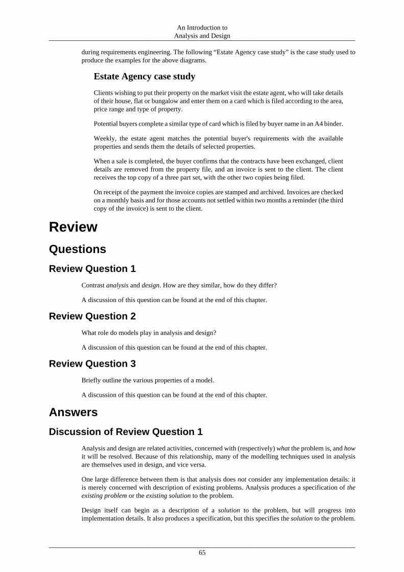
An Introduction toAnalysis and Design
65
during requirements engineering. The following “Estate Agency case study” is the case study used toproduce the examples for the above diagrams.
Estate Agency case study
Clients wishing to put their property on the market visit the estate agent, who will take detailsof their house, flat or bungalow and enter them on a card which is filed according to the area,price range and type of property.
Potential buyers complete a similar type of card which is filed by buyer name in an A4 binder.
Weekly, the estate agent matches the potential buyer's requirements with the availableproperties and sends them the details of selected properties.
When a sale is completed, the buyer confirms that the contracts have been exchanged, clientdetails are removed from the property file, and an invoice is sent to the client. The clientreceives the top copy of a three part set, with the other two copies being filed.
On receipt of the payment the invoice copies are stamped and archived. Invoices are checkedon a monthly basis and for those accounts not settled within two months a reminder (the thirdcopy of the invoice) is sent to the client.
Review
Questions
Review Question 1
Contrast analysis and design. How are they similar, how do they differ?
A discussion of this question can be found at the end of this chapter.
Review Question 2
What role do models play in analysis and design?
A discussion of this question can be found at the end of this chapter.
Review Question 3
Briefly outline the various properties of a model.
A discussion of this question can be found at the end of this chapter.
Answers
Discussion of Review Question 1
Analysis and design are related activities, concerned with (respectively) what the problem is, and howit will be resolved. Because of this relationship, many of the modelling techniques used in analysisare themselves used in design, and vice versa.
One large difference between them is that analysis does not consider any implementation details: itis merely concerned with description of existing problems. Analysis produces a specification of theexisting problem or the existing solution to the problem.
Design itself can begin as a description of a solution to the problem, but will progress intoimplementation details. It also produces a specification, but this specifies the solution to the problem.

An Introduction toAnalysis and Design
66
Discussion of Review Question 2
Models provide one of the primary means of communication of information during softwareengineering, especially during the activities of analysis and design. They allow us to simplify theinformation we wish to convey, and thus can highlight specific portions of the software system, suchas the static data design (class model), user interactions (use-case diagrams) and the flow of data (data-flow diagrams). They are a tool for abstraction (see Chapter 7, Design).
Discussion of Review Question 3
Models have the following properties:
• they consider only part of the system, focusing on particular aspects of the system
• they help to organise the analyst's ideas
• if the customer is able to understand the model, and is able to provide feedback on it
• omissions and errors should be easy to identify
• designers and programmers can produce the system from the models

67
Chapter 5. Object-oriented Analysisand Design
ObjectivesAt the end of this chapter you should be able to:
• Create class models of systems that can be encapsulated in one diagram.
• Simplify a model using generalisation and abstract classes.
• Describe how a more complex model can be specified, and how modelling software maintainsdesign integrity in such a complex system.
• Read and describe class models created by other designers.
• Be able to relate class diagrams to equivalent program outlines.
• Specify an object model using CRC cards.
• Describe how objects change over time.
IntroductionThis chapter discusses object-oriented modelling methods, that is, the representation of a softwaresystem in terms of classes and their inter-relationships. Class modelling is the most fundamental aspectof object-oriented analysis and design, and its mastery is crucial for anyone who intends to use object-oriented techniques. Class modelling is useful to both the analysis and design disciplines: in analysis,classes and the relationships between them will specify the problem. In design, it specifies the software.
Class modelling is philosophically complex, but practically straightforward. However, it rests on afew important philosophical concepts, and it is vital that these concepts are mastered before doing anypractical work. When students fail to make progress with real design exercises, it is commonly becausethey have not developed a proper understanding of the basic principles. These principles cannot belearned by rote, they must be understood through exercise and application.
Class modelling is used throughout object-oriented development, from analysis through toimplementation and testing. The class model is the “skeleton” on which the “flesh” of program codeis constructed. During the development of a system the class model is modified and refined, and oftenseveral different models will be used for the same software system, each model seeing the systemform a different standpoint, as will be discussed further below.
Modelling standpointsClass modelling is a flexible technique with a number of applications. In this it should be contrastedwith use case modelling; although the purpose of use case modelling is not specified in the UML, inpractice it is usually employed as part of a requirements elicitation exercise (as discussed in previouschapters). Class modelling, on the other hand, is used throughout an object-oriented analysis anddesign process, from requirements engineering through to programming.
The designer should have in mind at each stage of development what the class model is being used for.Neglect of this principle leads to poor design work. If you believe you have produced a class model

Object-oriented Analysis and Design
68
that represents “the system” (whatever the system happens to be), you are quite likely mistaken. Asingle class model at best represents a particular standpoint on the system.
Design standpoints represent the different uses we make of modelling. We can identify three obviousstandpoints.
• A logical design standpoint: the model shows how a system should function logically, or how itscomponents interact in a logical sense.
• A specification standpoint: the model shows how the system is broken into manageable components,and how those components interact.
• An implementation standpoint: the model shows how the system is structured, or how it will bestructured in the future.
Although these standpoints are not completely distinct, they do embody differences in how thesoftware system should be modelled. Specifically, you should see that analysis models will be moreof a logical standpoint, while design models will, ultimately, be an implementation standpoint.
As design progresses the standpoint of the designers will change. Initially — especially if the systemto be developed is replacing some other system or manual process — the designers will be concernedmostly with how the system is currently structured. This existing structure may well not be the mostefficient or logical, but it is necessary to understand the operation and context of the existing systembefore designing a replacement. Later, in the design process, the designers will be concerned with thelogical structure of the system. That is, regardless of how an existing system may be implemented, thedesigners consider what the simplest, most effective, logical organisation of the new system is. Stilllater, the designers will need to refine the model into a design that can be implemented. Here they willbe concerned with specification and implementation standpoints.
The UML provides a set of modelling symbols and terminology and defines the concepts that theyembody. The first job of the novice designer is to learn this notation and come to understand theconcepts. The UML does not specify how these concepts are to be employed. In other words, it does notprovide a different set of symbols for logical and implementation standpoints; it is up to the designerto ensure that his or her intentions are clear.
Classes and objectsThis section discusses the nature of classes and objects. We begin with the philosophical backgroundof classification and move onto descriptions of objects and classes that will be useful for softwareand system design.
ClassificationThe idea of classification is not a new one; philosophers have been studying the concept for at leasttwo thousand years. We classify things all the time: we classify people by gender or by age; weclassify motor vehicles by size, passenger capacity, and so on; we classify businesses into publiclyand privately owned entities, amongst others. When we classify something we are saying that it hasproperties in common with others of its type. The idea is, at heart, a simple one. We assume that if weknow something about the class, then that fact is true of all the members of the class as well. In writinga computer program that manipulates, say, customers' bank accounts, we need to be concerned first ofall with the things that all bank accounts will have in common. We do not want to be concerned withindividual customers unless there is something about them that is different to the class as a whole.This is a profoundly important and simplifying principle.
By being members of a class it is assumed that an object shares the general properties of the class. Forexample, all members of the class “human being” have certain properties in common; although thereare a great many different human beings in the world, they are sufficiently similar that there shouldbe no difficulty distinguishing between any human being and, for example, a cheese sandwich.

Object-oriented Analysis and Design
69
Classification in object-oriented designIn object-oriented design, we classify all the objects that a system should know about. That is, wespecifying classes that collectively describe all the behaviour of the system. Although we speakof object-oriented design, we are mostly interested in classes, rather than individual objects. Classmodelling is the process of assigning classes, and describing their inter-relationships.
Class modelling works in software design because it allows complex systems to be described in such away that the complexity becomes manageable. And all interesting (and most useful) software systemswill be complex.
The “things” that a software system will process, recognise and serve are, by definition, objects. Usersof the system, keyboards, screens, bank accounts, stock items, printouts, and so on, are all objects.By classifying these objects, that is, by creating and managing classes, the designers of the systemimpose some control on the complexity of the system. Although a complex system may manage manymillions of objects, it will frequently manage orders of magnitude fewer classes, perhaps fewer thanone hundred.
A definition of class and objectFor the purposes of object-oriented modelling, an object can be defined as follows:
An object is a self-contained entity with well-defined, recognisable properties(attributes) and behaviour (operations). It can interact with other objects.
This leads to the following definition of a class:
A class embodies the properties and behaviour that a collection of objects have incommon.
Examples of classesHaving presented this philosophical discussion, you may be expecting classes themselves to bephilosophical. In fact, they are usually not. Suppose we are designing a system to manage the work ofa lending library. Some of the classes that will need to be considered are:
• Book
• Member
• Reader
• Borrower
• Loan
• Fine
• Barcode
• Return date
Of course, on more detailed inspection these may turn out to be inappropriate, and no doubt manyother classes will have to be considered, but these initial ideas are appropriate classes because:
• they are self-contained with well-defined behaviour and properties
• each will have some instances (objects) that have a great deal in common

Object-oriented Analysis and Design
70
• it is obvious that each has an important role to play in the system
A further key point is that some classes may in fact have sub-classes. For example, “Reader” and“Borrower” may in fact be types of “Member”.
Some thoughts on the relationship between classesand objects
Here are some concepts to consider when thinking about classes and objects:
• In English we use the words “is a” to mean several different things. For example, in “Rover is adog” we are saying that Rover is an instance of class dog. When we say “A dog is a mammal”we are saying that “dog” is a sub-classes of “mammal”, that is, all members of class dog shareproperties with members of class mammal. Therefore, in describing the relationship between classesand objects, you should take some trouble to use unambiguous terms like “is an instance of” and“is a subclass of”.
• A class may have any number of instances, including one and zero. Classes can be defined that havezero members in practice and in principle. Student are often particularly reluctant to use classes thathave only one instance. The “Internet”, for example, is the one and only instance of class “Internet”.Again, this may seem odd, but class modelling is about classes, not individuals.
Concrete and conceptual classesPreviously we looked at some examples of classes that might be appropriate for a library computersystem. You should be able to recognise an important sub-grouping of these classes. Classes such as“Book” and “Member” are physical or concrete classes; they correspond to “real” things in the physicalworld. However, the classes “Loan” and “Return date” are different “types” of class. They do notcorrespond to real, physical entities at all. We will refer to classes of this sort as “conceptual” classes.Many student mistakenly use the term “abstract” here; this should be avoided because “abstract class”has a quite different meaning, which will be explained later.
Some components of a software system have both concrete and conceptual representation. Considerthe “Book” class: The conceptual book “War and Peace” by Tolstoy exists independently of the paperand binding of a real physical book; indeed the conceptual book may be said to exist if the only text inexistence was in a computer's memory. In other words, in a sense the book exists outside of its physicalrepresentation. At the same time, a lending library loans physical, not conceptual, books. They are realentities made of paper, with barcodes for scanning, and so on.
This is not purely an academic distinction. Large, complex systems (particularly object-orienteddatabases) may be impossible to implement unless this subtle distinction is understood. For example,if the library's system only represents physical books, it has to store all information about eachbook in each instance of the “book” class. But if the library has, say, ten copies of each book, thenmost of this information is duplicated in each object, which is a waste of memory and can causedata inconsistencies. This problem always arises when there is a distinction between physical andconceptual representations of the same thing, and when there are multiple, similar physical instancesof the conceptual item.
This is not an issue on which the novice designer should lose sleep; the majority of systems can bedesigned correctly even if the issue is not understood. However, it will improve the depth of yourunderstanding if you take the trouble to ensure that the sense of this section is understood.
Note
In an implementation, conceptual and physical classes will have different names to oneanother. For instance, the conceptual class “Book” might be named “BookInformation”,while the physical class may retain the name “Book”.

Object-oriented Analysis and Design
71
AttributesAttributes are the properties of a class; on the whole they are things that can be measured or observed.For example, an important attribute of the class Animal is “number of legs”. Different animals havedifferent numbers of legs, but all animals have the property “number of legs”. Even a snake has anumber of legs: it just happens to be zero. However, it would make no sense to talk about a plant'shaving “zero legs”. The attribute “number of legs” is not a valid attribute of plants.
Attributes are used rather vaguely in classification in general. For example, biologists distinguishbetween insects and spiders because insects have the attribute “has six legs” and spiders have theattribute “has eight legs”. There is a numerical difference here. However, one of the ways thatbiologists distinguish between reptiles and mammals is that reptiles are cold-blooded and mammalsare warm-blooded. There is no numerical difference in this case.
In class modelling the nature of attributes is formalised. We can say that:
An attribute of an object is a property that has a name, a value and a type. The nameand type must be identical for all instances of a class, but the value may be different.
For example, suppose the class “Book” in our library example has attributes “title”, “publisher”, and“date of publication” (there will, no doubt, be others, but these will do for now). The attribute “title”has a name (“title”), it has a type (probably “text” or “string”). Objects of class “Book” will havevalues for this attribute, for example, “War and Peace”. The attribute “date of publication” has a name,and its type is “Date”. Again, objects of class “Book” will be published on different dates, but allobjects will have a value for the attribute.
The important point here is that, although all instances of class “Book” have different values for theseattributes, they all have the attribute, and they are all the same type. The date of publication of a bookwill always be a date, and never a height. The title will always be a piece of text and never a colour,and so on.
In some cases the values of attributes distinguishes one object from another. For example, if Rover is abrown dog and Fido is a black dog, we may reasonably say that their “colour” attributes are different.There is no chance of confusing Rover for Fido. However, common sense indicates that if we seetwo brown dogs, we cannot assume they are the same dog: there are many brown dogs in the world.Indeed, even if all the attributes of two objects are identical, this does not make the objects identical.
There is an interesting philosophical issue behind this; many students have argued (sometime fiercely)in classes that if we really knew all the attributes of a particular class, and two objects had all thoseattributes in common, then they would of necessity be the same object. For example, two brown dogsmay be indistinguishable by colour, but the are distinguishable by position. If two putative objectsoccupy the same point in space, then they must be identical.
This is all well and good, but irrelevant for this subject. Whatever the philosophical contentions, theprinciple which object-oriented designers work to is that:
Two objects are not equal, or identical, just because they have identical attributes.Objects are only identical to themselves, or things that refer to themselves.
For example, the person Mary Smith is identical to herself, and if Mary Smith is the world-recordholder for (say) javelin throwing, then the object “Mary Smith” is identical to the object “world recordholder for javelin throwing”.
Ignorance of this principle leads to very subtle problems when designs are translated into programs.For example, consider the following portion of a Java program:
String response = "HELLO".toLowerCase(); if (response == "hello") {

Object-oriented Analysis and Design
72
System.out.println("They are identical."); } else { System.out.println("They are NOT identical."); }
This Java snippet creates an object of class String and sets it equal to the lower-case text "hello".The program then tests whether the “response” is equal to the object "hello". Since both objects havethe value “hello”, we might expect the program to consider them equal. But in fact the program willinform us that the two objects are not equal; the object "hello" and the object “response” have identicalattributes, but they are not equal to each other. The correct way to test whether two String objects haveequal attributes in Java is to write something like:
String response = "HELLO".toLowerCase(); if (response.equals("hello")) { System.out.println("They are equal."); } else { System.out.println("They are NOT equal."); }
The equals method tests two objects to see if their attributes are equal. The == operator, on the otherhand, tests whether the objects themselves are, in fact, the same object.
It is a key principle of object-oriented design that attributes should be simple. The technical term isatomic, meaning “not capable of division into smaller components”. If an attribute appears to haveattributes of its own, then it is not an attribute at all, and is probably an object in its own right. Youwill find that programmers, of necessity, do not follow this rule. This is because it is standard practiceto use classes to extend the functionality of a programming language. In Java, for example, numbers— such as 12 and 4.7 — are atomic, but text strings are represented as objects. In this case it is oftennecessary to make objects attributes of other objects.
Also, although “has six legs” may be an attribute of insects to a biologist, it will never be an attributeof any class in an object-oriented design. This is because it is not precise enough. A designer wouldsay that the class “insect” has an attribute “number of legs” whose value, by default, is 6. We wouldwrite this in a formal way (as will be discussed later):
numerOfLegs:integer(6)
Having said that, in the initial stages of design, it is inadvisable to be too precise about attributes. Inparticular, usually the names are established first before the types and values. In some cases the typesof attributes will not be determined until writing the program code; however, at this point it must bespecified: many programming languages require the types of attributes to be fully specified.
In addition, during design there is no reason why the types of attributes have to match the types thatare available to a particular programming language. For example, real numbers (that is numbers withfractional parts) are represented in Java by the types “float” and “double”. These are technical termswith no meaning outside of certain programming languages. In design there is nothing to prevent theuse of attribute types “number”, rather than “float”, simply because it is easier for non-specialists tofollow. The translation into programming terms can be made later in the development if necessary.
It is important to understand that an object's attributes belong to the object in some way, that is, theytend to be “private”. One object cannot automatically obtain, or change, the attributes of another. This

Object-oriented Analysis and Design
73
is just another way of saying the objects are self-contained. Part of the process of object-orienteddesign is determining which of an object's attributes may be read and written by other objects, andwhich will remain private.
Terminology note
Other terms for “attribute” include “instance variable”, “member variable” and “memberdata”, and may differ between programming languages (Common Lisp, for instance, uses theterm slot). Technically an “instance variable” is not exactly the same as an attribute, but thedistinction is not important enough to worry about at this stage. Java programmers tend touse the term “instance variable” rather than “attribute”, but “attribute” is preferred by mostdesigners and CASE tools.
OperationsIn the last section we considered attributes, which say something about what a class is. Operations saywhat a class does (or can have done to it). When you have fully specified the attributes and operationsof a class, then you have specified that class completely (some experts would say that one must specifythe class's constraints as well, but that is largely beyond the scope of this course).
For example, the “Clock” class may have the operation “display time”. This is something that a clockdoes. It is not an attribute of class “clock”, because it does not tell us anything about objects of classclock that we do not already know.
At the design stage, we tend to assume that all of a class's operations are accessible to other classes,that is, classes can communicate by invoking each others operations. This is called “message passing”.As design progresses, we usually find that new operations have to be added that are private to thatclass, because they are only concerned with internal operation of the class. Remember that classesshould be self-contained, and should expose as little as possible of their internal workings.
In the same way that attributes are formalised in object-oriented design, beyond what is true ofclassification in general, operations are also formalised. An operation has a name, a parameter list,and a return value, much like a function. The parameter list is (essentially) the data elements that willbe supplied to the operation. The return value is a piece of data that can be returned to the object thatinvoked the operation. These issues are not very important in the early stages of design (we may onlyknow the name of the operation), but become important as the design is translated into a program.Note that an operation has access to the object's attributes, and can read or write them, but normallyhas no access to the attributes of other objects.
Terminology
Other terms for “operation” include “member function”, “class function”, and “method”. Javaprogrammers tend to use the term “method”.
Dynamic behaviour and stateA class model, taken alone, is a description of the static structure of a system; this means that it showsthe system in a way that is independent of time. In the library system discussed earlier, the individualbooks may come and go, and individual members for that matter, but the classes “Book” and “Member”persist. To say that a lending libraries has books and members is true, independent of time.
Of course, in reality the system will change over time. This change is reflected in the values of theattributes of objects, and the numbers of instances of each class. The library may begin with 1000books, and ten years later it may have 10 000 books; but there will never be a time when the class“Book” is not a valid one for the library. Similarly, the addresses and even the names of the memberswill change. This will be reflected in the values of the attributes of the instances of class “Member”.

Object-oriented Analysis and Design
74
The sum total of information carried by the attributes of an object is called its state. If we know thestate of an object, then we know everything there is to know about it. This last statement is true bydefinition. If in describing an object the designer finds that its attributes are not sufficient to specifyits state completely, then they have overlooked some attributes.
If the state of an object is given by the values of all its attributes, then the state of the system if given bythe states of all its objects. In other words, the values of all the attributes of all the objects completelyspecify the state of the system at any given time.
If state is so important, why can it not be represented on a class model? The reason is that there arefar better ways to represent changes in state. The UML provides state transition modelling for thispurpose. In a full design it may be necessary to provide state transition diagrams for some or all classes,to describe their state changes in detail. The pattern of state change over time is called the dynamicbehaviour of a system, and modelling this is called dynamic modelling. As well as state transitionmodelling, the UML provides object interaction diagrams, activity diagrams, sequence diagrams andcommunication diagrams for dynamic modelling. One can, of course, describe the dynamic behaviourof classes in plain language as well, and one probably should.
Only objects have state; classes do not have a state. This is because a class specifies properties thatare true of all objects of that class. However, a class can have a default state. This is the set ofattribute values that an object of that class will have by default, that is, if not provided with any otherinformation.
UML notation and conventions
SymbolThe diagram below shows the UML symbol for a class formally (left) and as an example (right). Theformal detail looks quite daunting, but you will see that most of the information is optional, and inpractice a class symbol is quite straightforward.
Figure 5.1. The UML symbol for a class
The class symbol has three compartments. The top compartment shows the name of the class, anytags it has, and any stereotype it has. The stereotype of a class is a higher-level category to whichit belongs. Stereotypes are used to provide additional structure to a model, and to make it easier tofollow. Common stereotypes include «use case» and «actor». Most classes, in practice, will not needstereotypes. The designer is at liberty to create new stereotypes to organise the work, if required. Theonly tag that we will consider in this module is {abstract}, which will be discussed later.
The middle compartment contains the class's attributes. Each attribute can specify a name, a type anda default value. Only the name is compulsory.
The bottom compartment contains the class's operations. These can be specified in full, with parameterlists and return values, but very often only the name is given. To distinguish operation names fromattribute names, it is conventional to write an operation name with pair of brackets after it, like this:

Object-oriented Analysis and Design
75
push(). If the operation has a parameter list, then it can be written in the brackets, but, again, this isnot compulsory.
The example shows a possible class diagram for a “Button” class. By button we mean a little rectanglethat appears on the screen, and responds to mouse clicks, as with a computer GUI rather than a physicalbutton. In this example, the button has the stereotype «user interface elements». It is intended thatthis stereotype be applied to all classes that represent user interface elements, like list boxes, menus,windows, and so on. Again, this is not compulsory, but it helps structure the model. There are no tagsassociated with this class, so none are shown.
The “Button” class has a foreground colour and a border colour, and these can be changed. So we havedefined two attributes to store the colours. These attributes have type “colour”. Most programminglanguages do not have an inbuilt “colour” data type, and at some point the programmer will have totranslate this type name into something that the programming language will understand. This is notan issue for the early stage of design. It is clear what “colour” means, and this is the important factor.
The operations of the class are “push()”, meaning simulate what happens when a button is pushed(probably the screen appearance will change), and two operations to change the colours. Why cananother class simply not change the attributes to change the colour? It is vital to understand that a classshould be, as far as possible, self-contained. It is up to the class to decide whether its colours can bechanged or not, and by which other objects. The operations to change that colour will probably changethe values of the colour attributes, but it is up to the implementer of the class to decide how this willhappen. Another class does not need to know the internal operation of the “Button” class.
The operations that set the colour each have a parameter list with one parameter: the colour to be used.
You will see that the example class is very much simpler than the formal specification. In practice,it is common for classes to start of with very little detail (no parameters, no types), and to be “filledin” as design progresses.
A note on software
The class diagrams were created using a commercial package, Select SSADM. Varioussoftware packages may support the UML notation to a greater or lesser degree, and sodiagrams made using different packages will differ from one another.
Naming conventionsThe UML makes certain recommendations about how names of things are to be written, withvarying degrees of force. We recommend that you follow the UML naming conventions as if theywere all compulsory, because most professional designers do, and you will want your work to beunderstandable by your colleagues. The naming conventions are also in line with the Java namingconventions, and should be familiar.
• Names of classes are written with an initial capital letter (like this: Button, not like this: button)and have no spaces. To show where a space would be, the next letter is capitalised (like this:BarcodeReader, not like this: Barcode Reader).
• Class names are singular, not plural. It is incorrect to name a class “Books”. Although there maybe many book objects, there is only one book class.
• Names of attributes and operations start with a lower-case letter, but may have capital letters toindicate where the spaces would be, if the name would normally have spaces.
• Names of operations are followed by brackets () to distinguish them from names of attributes
The prohibition against spaces arises because most programming languages do not allow spaces intheir naming convention, and it is modern practice for the final model diagrams to be as close to aprogram as possible. Some, but not all, CASE packages will enforce these conventions.

Object-oriented Analysis and Design
76
Finding classesThe customers of a software engineering project will not think of their work in terms of classes; it isthe job of the developers to determine suitable classes with which to structure their work. This jobrequires experience and intuition, and invariably improves with practice. Here are a few general hints:
• The names of classes are usually nouns. A good place to start is to take a written description of thesystem and select all the nouns. You will undoubtedly have to remove some classes and add others,but this method provides a place to start.
• It is better to have too many classes to begin with, rather than too few. You can always removesome if you find that they are redundant
• Classes should, as far as possible, correspond to entities that the clients would understand. Computerterms rarely make good class names. You will find that as development progresses you will needto add classes to represent implementation factors, but you should not start off with these. Classesshould make sense to non-technical people, at least in the early stages.
• If something has sub-types, or it is a type of something else, it is probably a class
• If something is important, but does not appear to be a class, it might be an attribute of some otherclass
As you add detail to a design you will discover new classes, and you can add these to the model. Youwill also often find that you can simplify a design by adding classes, as will be shown.
At all stages of development you should challenge your class model and be prepared to modify itif necessary. It is important to remember that iterative, incremental and evolutionary methods willhave you update not only requirements, but the software design (and hence class model) for multipledevelopment iterations. This is especially important for agile process methods.
Relationships between classesFinding and describing classes is the first stage of class modelling. The next stage is to determine, andshow, how classes are related.
In the simplest terms, a relationship between two classes is shown by a line (as it is in an entity relationdiagram):
Figure 5.2. A relationship between two classes
In general such a relationship is referred to as a link, association, or a collaboration.
In the diagram above, the classes are shown with horizontal dashes where the operations and attributesnormally go; this is an indication that there are some operations and attributes, but they are not shownon this diagram. It is also permissible to show a class simply as a rectangle, but then the reader does

Object-oriented Analysis and Design
77
not know whether the class has attributes and associations and they are not shown, or if it does nothave any at all.
The line connecting the two classes has an arrow to indicate the direction of the association. Objectsof class “LibraryMember” borrow objects of class “Book”, not the other way around. This is fairlyobvious from the context in this example, and the arrow could have been omitted, but if you areworking on a system which is less obvious it does well to include the arrows. Note that links shouldhave names, although you will not always want to show the name on the diagram (to reduce clutter).If you cannot assign a sensible name to a link, it is probably not a real link, or the classes at eachend are incorrect. Normally a link should be able to have a relatively simple, short name, which willprobably be a verb.
The UML is strict about the positions of arrows. It would be incorrect to draw the arrow in the figureabove on the line. Arrows on lines have a different meaning altogether.
The links shown above is an example of a “named association”; it is the most general kind of link.The UML also recognises a number of special-purpose links, which will be described later.
Specifying relationships in detailIf a link is drawn as a simple line, it is assumed to be a one-to-one association. In the previous examplethis would mean that each member of the library can borrow exactly one book, and each book can beborrowed by exactly one member. This is probably not correct. It is good practice to indicate on eachend of the link its multiplicity, that is, the number of objects associated with the link. It is particularlyimportant to distinguish between “1” and “many” in multiplicities.
We could re-draw the previous example like the figure on the left:
Figure 5.3. Indicating multiplicity
This indicates that at any given time a “LibraryMember” is involved with a “borrows” associationwith an object of class Book, that is, a library member can borrow up to six books. At the same time,a book can only be on loan to one member.
The figure on the right is an example of a many-to-many relationship. A student can be studying one,two, or three courses at a particular time. Each course can be studied by an indeterminate number ofstudents. The symbols “M” stands for “many”, and means “some unspecified number”. The asterisk(*) can also be used to stand for “many”. Note that the UML distinguishes a many that may includezero from a many that does not. In the “students” example, the number of students enrolled on a coursevaries from zero up to many, not from one up to many.
The multiplicity symbols are an example of what the UML specification calls end ornamentation.End ornaments are symbols that can be used on the ends of associations to enhance their meanings.Another common end ornament is the navigability arrow. This is an arrow drawn on (not alongside)the line and indicates the direction in which the class structure can be traversed for information.

Object-oriented Analysis and Design
78
InheritanceWe indicated earlier that object-oriented modelling recognised some specialised types of associations.The first, and most important, of these is the generalisation-specialisation association. You will haveencountered this previously in when studying use case modelling; it is now time to examine thisrelationship in more detail.
As a reminder, the symbol for a generalisation-specialisation relationship is shown below:
Figure 5.4. Generalisation-specialisation represented in the UML
The arrow points towards the most general class. In this example, we are considering part of a system tobe used by an estate agency for assisting in finding suitable premises for small businesses to purchase.The class “Premises” represents any premises. Its important attributes are the address, floor size, typeof use permitted, amount of parking space, price expected, and so on, but these are not all shown in thediagram for reasons of lack of space (ellipses are used to indicate this). There are two important sub-classes of premises: leasehold premises, and freehold premises. These have all the same properties of“Premises”, and some additional ones. For example, leasehold premises will naturally have an addressand a size, but they will also have a lease duration, a ground rent, and some others. Similarly, freeholdpremises will have properties that are not applicable to leasehold premises, or to premises in general.
It would be an error to show the attributes “address”, “floor area”, and so on, in “LeaseholdPremises”and “FreeholdPremises”. These classes will automatically have these properties, as they will inheritthem from “Premises”. The same mechanism applies to operations: any operations of “Premises” willapply also to its sub-classes and should not be shown again in the diagram except if the sub-classesdo different things in these operations.
There may also be sub-classes of “LeaseholdPremises” and “FreeholdPremises”. These will inheritthe properties of all their super-classes. So classes can form a complex hierarchy. When a sub-classinherits properties from a class other than its own base class, this is called indirect inheritance.
Terminology
A variety of different terminology is used to denote different parts of a generalisation-specialisation relationship. Using the above figure as an example, we could say:
• “Premises” is a generalisation of “LeaseholdPremises” and “FreeholdPremises”
• “Premises” is the base class of “LeaseholdPremises” and “FreeholdPremises”
• “Premises” is the super-class of “LeaseholdPremises” and “FreeholdPremises”
• “LeaseholdPremises” and “FreeholdPremises” are sub-classes of “Premises”

Object-oriented Analysis and Design
79
• “LeaseholdPremises” and “FreeholdPremises” are specialisations of “Premises”
Multiple inheritance
It is possible for a class to be a sub-class of more than one base class.
For example, “Radio” and “Television” are sub-classes of “ElectronicDevice”. “Television”and “Car” are sub-classes of “TaxableProperty”. “Television” inherits properties of“ElectronicDevice” and of “TaxableProperty”. “Radios” are not taxable, and therefore cannotbe a sub-class of “TaxableProperty”. “Cars” are not electronic. This is a clear example ofmultiple inheritance. This example is quite artificial, to illustrate a case where it is difficult toavoid multiple inheritance. In many cases it will be possible to restructure a model to avoid it.Note that some programming languages (including Java) do not allow multiple inheritance,so many designers avoid it as well.
Abstract classesAn abstract class is one that can have no direct instances.
An abstract class has no direct instances logically, or by definition. But a class isnot abstract merely because it happens to have no instances. For example, the class“PersonWhoCanRunAMileInLessThanThreeMinutes” happens to have no instances at present, butthere is no logical reason why this should be the case. No doubt careful use of performance-enhancingdrugs and twenty years of selective breeding could cause this class to be instantiated. For a class to beabstract it must be logically impossible, not physically impossible, that it be instantiated.
In addition, a class is not abstract merely because it does not correspond to a real-world entity.This mistake is commonly made by novices; it is not unusual to see beginners label classes like“BankAccount” or “Transaction” as abstract because they represent non-physical things. The correctterm for these classes, as mentioned earlier, is conceptual.
As an example, consider a computer system that manages information about certain products that abusiness manufactures. The bulk of information about a product (e.g., price, delivery time, warrantyduration) is encapsulated in a class called “Product”. However, we may choose to create classes torepresent the specific products we produce, and have them as sub-classes of “Product”. In this case,by definition there are no direct instances of class “Product”, but there will be instances of the sub-classes of “Product”. Because “Product” is never directly instantiated, it is an abstract class.
What is gained by doing this? In short we have gained a measure of simplicity. By gathering mostof the important information about the products into a single class (“Product”) we have removed theneed to duplicate this information in the different sub-classes of “Product”.
Making “Product” abstract has two important benefits. First, the reader of the model will knowimmediately that “Product” has a particular role in the system, that of providing structure andsimplification. Second, the compiler that generates the final program will know that there can be nodirect instances of class “Product”. This means that (i) it does not have to use memory to store thedetails of the instances, because there are none, and (ii) it is able to prevent the programmer makingsome trivial mistakes. Consider this definition in Java:
abstract class Product { //... details go here }
If the program attempts to create an object of this class later, it can only be because the programmerhas made an error. The compiler will flag any such attempt as a compile time error.

Object-oriented Analysis and Design
80
An abstract class can have abstract operations. These are operations that are specified, but notimplemented. It is up to the subclasses to provide a full implementation of the abstract method.
An abstract class with no-subclasses is more than likely useless. If you find this on your models youhave probably made a mistake.
It is possible to indicate that a class is abstract in a class diagram by adding the {abstract} tag beneaththe class's name.
Aggregation and compositionAll object-oriented designers use generalisation-specialisation relationships all the time. They are vitalto good design. The relationships we will consider in this section are defined by the UML, but it is notgenerally agreed that they are a special kind of association at all.
AggregationAggregation is a general term for any whole-part relationship between objects. Its symbol is a whitediamond, like this:
Figure 5.5. The representation of aggregation in the UML
This diagram can be read as “an Army is an aggregate of one or more soldiers and one or moreweapons”. The aggregation is expressing a loose whole-part relationship between the army and itsconstituents, where the constituents are not necessarily members of the aggregate. For example, if thearmy as an entity ceased to exist there would still be soldiers (they would simply be unemployed).This topic has lead to some very heated debate. In practice the distinction between a computer systemwhich works, and a system which does not, is highly unlikely to hinge on whether the designers usedaggregations or named associations. An aggregation can usually be replaced by an association called“has” without much loss of clarity.
CompositionIt is not clear that composition is more expressive than a simple association labelled “contains”.Composition expresses a whole-part relationship where the “parts” are definitely contained withinthe “whole”.
Figure 5.6. The representation of composition in the UML
This example can be read as “a book consists of one or more pages, and one binding”. Note thedistinctions between this and the previous example. First, the binding and pages physically comprise

Object-oriented Analysis and Design
81
the book; it is impossible for the binding and pages to be in one place and book in another. Second,destruction of the book would imply destruction of the binding and pages.
Self-association and rolesSo far we have shown how classes can enter into associations with other classes. However, it isallowable — and often essential — to model a class as being associated with itself. For example,suppose we are designing a system for managing contracts, and we want to show that a contract canconsist of a number of small sub-contracts. Sub-contracts have exactly the same properties as contracts.We could represent this as follows:
This example says that one object of class “Contract” consists of zero or more objects of class“Contract”. To clarify the relationship, it is customary to use role names. Where an association namedescribes the overall nature of the association, a role name is attached to the end of an association, anddescribes the role played by the object at that end. If the example above, one object plays the role of“main contract” while zero or more others play the role of “sub-contract”. Because role names are soimportant in these cases, some CASE tools will report an error if they are omitted.
Link classes and link attributesIn many cases each instance of an association has properties of its own. It is sometimes helpful to showthis in the model for increased expressiveness. In addition, it gives us a way to show that multipleclasses are involved in the same association.
A link attribute simply assigns a value to a particular instance of the link, that is, for each pair ofobjects that are associated there is a particular value of the attribute. For example, in the top diagramof the figure shown below:
Figure 5.7. Link attributes
“transactionNumber” is a link attribute. This model says that the bank and its customers enter intotransactions, and each transaction has a particular number.
However, the association may be too complex to be represented by a single attribute. In this case wecan use a link class. With a link class there is one instance of the class for each pair of objects that

Object-oriented Analysis and Design
82
are associated. The link class can have any number of attributes, and can quite legitimately enter intorelationships of its own with other classes in the system. In the example above, the link class “Number”defines each transaction carried out by the bank with its customers. It has attributes to indicate thenature and date of the transaction, as well as the number. Link classes can also have sub-classes. Forexample, it may be useful to indicate that there are different types of transaction by means of sub-classes, rather than simply having an attribute called “type”.
Link classes are a very powerful and expressive tool, but do take some experience to able to useeffectively.
Constraints and notes
NotesAs in use case modelling, it is often very helpful to be able to annotate a diagram to show particularfeatures. The notation is exactly the same:
Figure 5.8. The notation for notes
You can, and should, apply notes wherever you think they will be helpful to the reader, but theyshould not be viewed as a substitute for proper documentation. A class model is not complete until allclasses, attributes, operations, and associations, have been documented. Notes are useful for pointingout specific details on diagrams.
ConstraintsConstraints are additional information about a class that are not associated with any particular attributeor operation. A typical constraint might say, for example, that one attribute will have a value whichdepends on some other attribute. It is customary to write simple constraints below the class in braces,{like this}.
Constraints are becoming increasingly important in object-oriented modelling, as there is an increasinginterest in formalising the technique. A scheme called the object constraint language is underdevelopment to support formalised constraints, but this is beyond the scope of this course.
Class-Responsibility-Collaborator cardsClass-responsibility-collaborator cards (CRC cards) are not a part of the UML specification, but theyare a useful tool for organising classes during analysis and design.
A CRC card is a physical card representing a single class. Each card lists the class's name, attributesand methods (its responsibilities), and class associations (collaborations). The collection of these CRCcards is the CRC model.
Using CRC cards is a straightforward addition to object-oriented analysis and design:
1. Identify the classes.
2. List responsibilities.
3. List collaborators.

Object-oriented Analysis and Design
83
CRC cards can be used during analysis and design while classes are being discovered in order to keeptrack of them.
CRC cards have various benefits, which you might notice makes them very amenable to iterative andincremental process models, especially agile ones:
• They are portable: because CRC cards are physical objects, they can be used anywhere.Importantly, they can easily be used during group meetings.
• They are tangible: the participants in a meeting can all easily examine the cards, and hence examinethe system.
• They have a limited size: because of their physicality, CRC cards can only hold a limited amountof information. This makes them useful to restricting object-oriented analysis and design frombecoming too low-level.
Class responsibilities are the class's attributes and methods. Clearly, they represent the class's stateand behaviour. Collaborators represent the associations the class has with other classes.
CRC cards are useful when the development of classes need to be divided between software engineers,as the cards can be physically handed over to them. A useful time to do this is when classes are beingreviewed, for, say, determining whether they are appropriate in a design.
From model to programDuring object-oriented development, the models will tend to become more detailed, and there willbe a shift in standpoint from a logical to an implementation view. Developers using the waterfall orsimilar process models feel that there should be a strong correspondence between the final model andthe program code it results in. However, iterative and agile methods often eschew heavy amounts ofdocumentation, and realise that models (including object models) may not always accurately reflect thecode, since both will always be changing as the code-base develops, and as the customers' requirementsdevelop over time.
For agile methodologies it is important to remember that documentation is secondary to the softwarebeing produced. Slavishly attempting to specify every last component of the software in a detailedobject model is antithetical to agile process methods, and there are many published studies showingthat such complete, upfront designs are both inadequate (since requirements, and hence designs,continuously change) and detrimental to software engineering as a whole.
Dynamic behaviourThe object model which we have just been discussing is a static model of classes and theirrelationships. It does not show how the classes call on one another to perform the functions requiredin the software system.
These dynamic aspects of the object model are usually represented in other diagram types of the UML.We will be briefly discuss interaction diagrams.
Interaction diagrams
Interaction diagrams show how objects interact with one another. Specifically, they show whichobjects are currently executing, and what methods they are calling on other objects.
There are various kinds of interaction diagrams that can be employed in the UML. We will examineone specific type, the sequence diagram. Sequence diagrams show how objects interact with eachother over time. In other words, sequence diagrams show the sequence of interactions between objects.

Object-oriented Analysis and Design
84
Figure 5.9. Sequence diagram notation in the UML
: Borrower : Catalog : Book
: checkOut
: requestBook
: isAvailable
The figure above shows a sequence diagram of how books are checked out of a library. Notice howthe objects are arranged horizontally along the top of the diagram, and are represented as rectangleboxes, just as classes are. It is important to notice the colon before the class name in these boxes —this colon tells us that the box represents not a class, but an instance of the class. If the instance shouldbe given a specific name, then the name appears before the colon. For example, “artOfWar : Book”represents an object called “artOfWar”, of class “Book”. This is exactly the same as when specifyingattributes in classes (see the section called “Attributes” above).
It is important to realise that it is because sequence diagrams represent the interactions a softwaresystem undergoes over time that it is interested in objects rather than classes. A running softwaresystem consists of instances of classes, and not of the classes themselves.
Time is represented vertically, with earlier events happening closer to the top. This means thatsequence diagrams should be read from top to bottom. Each object also has a vertical life-line thatshows us the object's period of existence. Interactions are represented by solid and dotted lines, eachof which has an arrow and a label. Solid lines show method calls, and point from the life-line of theobject making the call towards the object which will execute the method. The rectangles along the life-line represent the time over which an object is executing a function. Dotted lines represent a return ofcontrol from the object executing a method to and object which had originally called it.
Note that the method names should be operations belonging to the object to which the arrow is pointing.“Borrower” calls “requestBook”, an operation belonging to an instance of class “Book”.
A useful way of using sequence diagrams is to outline difficult use cases as a sequence diagram: thiswill highlight what objects are required in developing the use case, as well as what actions each objectwill perform in order to complete the use case. Further, a sequence diagram can then be thought of asshowing how the system reacts to events, the events being the input from the actor in the use case.
The UML also prompts us to use sequence diagrams in this way: remember that actors in use casesare themselves classes. We can easily use instance of these classes (of these actors) as valid objectsin sequence diagrams.
Summary
Class modelling is the key modelling technique for object-oriented designers. If you are in a positionto say that you understand class modelling, then you can reasonably claim that you understandobject-oriented design. Of course, an understanding of other object-oriented techniques (e.g., use casemodelling) will also be helpful.

Object-oriented Analysis and Design
85
Class modelling centres on a small number of philosophical points, which must be understoodextremely well. There is not a great deal of factual material to remember, but these key points arecrucial. These are the most important issues:
• The distinction between objects and classes
• The nature of attributes and operations
• The use and specification of associations, especially generalisation
In constructing a class model, the first step must be to obtain a working list of candidate classes. Asdesign progresses, these classes will be refined and some will be deleted. At an even later stage, newclasses will be introduced to support more detailed, implementation-related concepts.
A class model is refined by finding and specifying associations. Doing this helps to determine whetherthe initial choice of classes is a sound one, and how to improve it.
Ultimately the class model will be transformed into a computer program.
ReviewQuestions
Review Question 1
Which of the following entities are likely to be of interest when considering system design from a“logical” point of view, and which from an “implementation” point of view? Which are relevant toall standpoints? Clerk; Screen; Mouse (the input device, not the rodent); File; List; Ledger; Servicetechnician; Database; Customer;
A discussion of this question can be found at the end of this chapter.
Review Question 2
Fill in the gaps with an appropriate word or phrase, or select the correct one of the indicated choices:
A class encapsulates the behaviour and properties of a number of [__________]. The membersof a class are also referred to as [__________]. The minimum number of instances of a class is[__________], the maximum is [__________]. In object-oriented design, an object [can/cannot] be bea instance of more than one class, and an object [can/cannot] change which class it is an instance of.
A discussion of this question can be found at the end of this chapter.
Review Question 3
Suppose you are designing a computer system to carry out stock control in a large book warehouse.The system should store extensive details of each book, including at least the following information:authors, title, publisher, date of publication, size, number of pages, binding format, shelf location, re-order level, purchase price, sale price. Which of these properties of books do you think are relevantto the conceptual class “Book”, and what properties to the concrete class “Book”? This problem issomewhat more difficult than it first appears; see the answer for further discussion.
A discussion of this question found at the end of this chapter.
Review Question 4
Fill in the blanks with an appropriate word or phrase:
Attributes define the properties of a class. In a class specification an attribute has a [__________]and a [__________] (e.g., number, text). In each object of that class the attribute will also have a

Object-oriented Analysis and Design
86
[__________]. This may be different for each object, but no instance of the class will lack the attributeentirely. For example if I say that a particular vehicle has 12 wheels, I am implying that vehicles havea attribute whose name is “[__________]”, whose type is “[__________]” and whose value in theparticular case is [12]. The minimum number of attributes that a class may have is [__________]. Themaximum number is unlimited, but in practice it is difficult to manage a class with more than about 30attributes. Java programmers tend to use the term [__________] in preference to attribute, but theseare essentially the same thing.
A discussion of this question can be found at the end of this chapter.
Review Question 5
Draw a UML class symbol that has the following specification. The class is called “Customer”. It hasfour attributes: name (which is text), address (also text), balance (a number), and credit rating (typecurrently unknown). It has one operation: “printStatement()”, which has no parameters or return value.
A discussion of this question can be found at the end of this chapter.
Review Question 6
In the early stages of development it is usually better to identify too many classes than too few. Youcan then rationalise you choice of classes by removing, modifying and merging them. The followinglist is of classes that may be considered for deletion or absorption into a new class. Suggest why thismight be the case for each example.
• Fred Bloggs, a customer of the bank
• Colour
• Hard disk
• Central processing unit
• Linked list
• Red
• Test procedure
• List of customers
For as many of these examples as you can, suggest an application where it is not a bad choice of class.
A discussion of this question can be found at the end of this chapter.
Review Question 7
Draw the class diagram for the radio/televsion/car example given in the text, showing where multipleinheritance occurs.
A discussion of this question can be found at the end of this chapter.
Review Question 8
Construct a class model to represent the following information. The customer is a company thatspecialise in the supply of specialist musical recordings, of the type that are difficult to obtain throughmainstream record shops. The customer would like to make it possible for their clients to order theirproducts on-line using a Web browser. The on-line system is to provide full details of each musicalrecording, and will be integrated into an automated stock control system. In this way their client will

Object-oriented Analysis and Design
87
be able to tell immediately if the items required are in stock. The customers describes the details oftheir stock as follows:
We stock about 10,000 different musical recordings, usually with 1-10 of each itemin stock at any given time. With more popular items we will stock ten or more copiesof the same recording, perhaps in different formats.
We stock recordings in different formats: cassette tapes, audio CDs and audioDVDs. The publishers we buy from will normally supply a recording in more thanone format. For example, usually we will get CDs and cassettes of a given recordingfrom the same publisher.
We buy our stock from music publishers. For each publisher we record the nameand address, and the name and e-mail address of our contact person there. When weplace an order we need to know the publisher's catalogue number, which is generallydifferent for different formats.
When a customer looks at our Web site, we want to be able to give extensivedetails for all our recordings. For example, we will want to display the title,performer, composer, date and venue of recording, copyright holders and somegeneral information. In addition, we want to display the titles and durations of allthe musical tracks. This is complicated by the fact that the CD, DVD and cassetteformats generally don't have the same tracks. Because a DVD is longer than a CD,it will usually have a few extra tracks. A cassette tape usually has even fewer tracksthan the CD.
A discussion of this question can be found at the end of this chapter.
Review Question 9
Redraw the contract-subcontract relationship shown below so that it does not use a self-association.Do you think your model is more or less expressive in this form?
A discussion of this question can be found at the end of this chapter.
Review Question 10
What is meant by the statement “objects are not classes, but instances of classes. However, classescan be considered objects”? In other words, in what sense is a class also an object? (This is a trickyquestion if you are not absolutely clear on the distinction between “classes” and “objects”).
A discussion of this question can be found at the end of this chapter.
Review Question 11
Write a simple, one-line definition of each of the following key terms. Try to do this without referringback to the notes if possible. For each term, give an example.
• Attribute
• Operation
• Self-association

Object-oriented Analysis and Design
88
• Generalisation
• Polymorphism
• Link class
• Multiplicity
• Stereotype
A discussion of this question can be found at the end of this chapter.
Review Question 12
Which of the following are true? Give an example to support your decision.
• If Z is a subclass of Y, and Y is a subclass of X, then Z is a subclass of X
• If Z is associated with Y by an association A, and Y is associated with X by an association A, thenZ is associated with X by an association A
• If Z is associated with Y by an association A and by an association B, then A and B are differentnames for the same association
• If each object of class Z is associated with ten objects of class Y, and each object of class Y isassociated with ten objects of class X, then there are 100 objects of class X for each object of class Z
A discussion of this question can be found at the end of this chapter.
Review Question 13
What is the difference between class modelling, and entity-relationship modelling? In what ways areclasses and entities similar? In what ways are they different? (If you have not completed the part ofthe course that deals with entity-relationship modelling, you may find this question difficult).
A discussion of this question can be found at the end of this chapter.
Review Question 14
Consider these three classes: Rectangle, Circle, and Line, which are subclasses of a general Shapeclass. These classes have operations drawRectangle(), drawCircle(), and drawLine() respectively.Each of these methods cause the appropriate shape to be drawn. Is this system exhibitingpolymorphism or not?
A discussion of this question can be found at the end of this chapter.
Review Question 15
What is the difference between a link class and a link attribute? Gives examples of each.
A discussion of this question can be found at the end of this chapter.
Answers
Discussion of Review Question 1
Probably “Clerk”, “Customer”, “Ledger” and “Service technician” are important in a logicalstandpoint. None of these are likely to transform directly into parts of a computer program. On the otherhand, “File”, “List” and “Database” probably will. “Screen” and “Mouse” are less easy to categorise.In some cases these will in fact simply be alternative representations of the human beings that willinteract with a system. For example, a clerk may use a keyboard and a mouse; in some systems it is

Object-oriented Analysis and Design
89
the fact that these particular devices are in use that is important, but in most it will be the person andthat person's role that are important.
Discussion of Review Question 2
A class encapsulates the behaviour and properties of a number of [objects, entities]. The membersof a class are also referred to as [instances]. The minimum number of instances of a class is [zero],the maximum is [unlimited, infinite]. In object-oriented design, an object [cannot] be be a instance ofmore than one class, and an object [cannot] change which class it is an instance of.
Discussion of Review Question 3
Some things are clearly properties of the conceptual class. For a book, things like the title, author,date of publication and publisher are probably conceptual. They will be independent of any physicalrealisation of that book. For example, there are many copies of Tolstoy's “War and Peace” in existence,in many different formats, but all share the same fundamental properties.
In a library, the shelf location and bar-code number are properties of the physical book.
Less straightforward cases are properties like the format (size, shape, binding) of the book. Theseare clearly “concrete” properties. However, there are many different copies of each of these formats.Are these individual copies “physical” and the formats themselves “conceptual”? This is not astraightforward question. It may be in a very complex book handling system that we have to institutea number of different classes to represent book information.
Discussion of Review Question 4
Attributes define the properties of a class. In a class specification an attribute has a [name] and a [type](e.g., number, text). In each object of that class the attribute will also have a [value]. This may bedifferent for each object, but no instance of the class will lack the attribute entirely. For example if Isay that a particular vehicle has 12 wheels, I am implying that vehicles have a attribute whose nameis “[number of wheels]”, whose type is “[number, integer]” and whose value in the particular caseis [12]. The minimum number of attributes that a class may have is [zero]. The maximum numberis unlimited, but in practice it is difficult to manage a class with more than about 30 attributes. Javaprogrammers tend to use the term [instance variable] in preference to attribute, but these are essentiallythe same thing.
Discussion of Review Question 5
Discussion of Review Question 6
Bad classes:
• Fred Bloggs, a customer of the bank: this is potentially a bad class because Fred Bloggs is an object(instance), perhaps of class Customer. It is unlikely that there will be a whole class of Fred Bloggses.
• Colour: colour is likely to be an attribute of something. If you have studied Java programmingyou will probably come across a class called Colour. However, Java does this as an extension of

Object-oriented Analysis and Design
90
the language, not because Colour represents anything in a model. However, in a program for, forexample, colour mixing in printing machinery, perhaps Colour is important enough to be a classin its own right.
• Hard disk: this is a bad class because it is concerned with the internal operation of the computer.In modelling, we want to avoid detail of this depth. “Document” and perhaps “Folder” may bereasonable modelling concepts. However, in an application to design computers, HardDisk may bea sensible class.
• Central processing unit: has all the same problems as the example above
• Linked list: if you didn't know what a linked list was, then that is as good a reason as any for gettingrid of it. Even if you did, it is still too technical to use in modelling
• Red: is probably the value of an attribute
• Test procedure: this is probably an operation, or perhaps a use case
• Print: this is almost certainly an operation (or a Printer class perhaps?)
• List of customers: too much detail. “Customer” is a sensible class name. The fact that there are morethan one customer should be represented by the multiplicities of associations with other classes(see later).
Discussion of Review Question 7
This is a somewhat contrived example, and is unlikely to occur in a real application. However,multiple inheritance does occur in real applications all the time. It is probably more important inprogramming, rather than modelling as such. For example, a popular style of programming called“mix-in” programming makes extensive use of multiple inheritance. In mix-in programming a largenumber of very simple, general-purpose classes are defined, and these are inherited in variouscombinations by the major classes. Because something is important in programming, this does notnecessarily mean it should be used in modelling. This topic is an important and controversial one.
Discussion of Review Question 8
There is no single right answer to this question. You should be prepared to discuss you solution withyour tutor/classmates (hint: a good answer will probably contain between 5 and 10 classes).
Discussion of Review Question 9

Object-oriented Analysis and Design
91
In this alternative formulation, there is no self-association, but a SubContract is shown as a sub-class ofContract. The representation that used a self-association did not make this class/sub-class relationshipexplicit; indeed it may not really be true. If one is prepared to accept the implicit assumption thatSubContract is a sub-class of Contract, then the diagram shown above does effectively remove the self-association. This may be a reasonable approach for someone who really find self-associations difficultto follow. So perhaps some improvement in expressiveness has been gained, but at the expense of aslight loss of accuracy.
Discussion of Review Question 10
Suppose a class model has three classes, called ClassA, ClassB and ClassC. Objects of these classeswill share properties (this is the definition of being an instance of a class, after all). However, the classesthemselves will also have properties in common. For example, they will all the attribute “name”. Itsvalue is “ClassA” for ClassA, “ClassB” for ClassB, etc. All classes will have the property of being ableto enter into relationships with other classes. All classes will have the attribute “numberOfAttributes”.Thus we can say that there is a class called “Class”, which embodies the behaviour of all classes. Eachactual class is an instance of class “Class”.
This is not simply an academic point. Being able to express a modelling notation in terms of themodelling notation itself is a very powerful way to ensure that the modelling system is consistent. Ifyou study the UML specification documents, you will find that all UML diagram rules are themselvesspecified in UML notation. This is called meta-modelling
Discussion of Review Question 11
• Attribute: a property that objects of a class have, that can be expressed in terms of a name, a typeand a value. For example, class “Vehicle” has attribute “numberOfWheels”. Different vehicles havedifferent values of this attribute.
• Operation: a well-defined unit of behaviour of an object of a class. For example, class Vehicle hasoperation “startEngine()”.
• Self-association: an association between one or more objects of a class, and one or more objectsof the same class. For example, each object of class “LivingThing” is involved in a one-to-manyassociation called “eats” with other objects of the same class (technically I suppose that some livingthings don't eat other living things, but I hope you get the general idea).
• Generalisation: the property that a class has of representing behaviour and attributes of a numberof subclasses. For example, class Vehicle generalises classes Car, Bus and Tram, etc.
• Polymorphism: differences in behaviour between different sub-classes of the same base class.For example, all sub-classes of Vehicle have the operation “startEngine()”, but the mechanism ofstarting the engine is different in each case.
• Link class: a class that specifies the details of an association between two other objects. Forexample, the relationship between a seller and a buyer may be complex enough to need a class (e.g.,SalesTransaction) to represent its details.
• Multiplicity: the number of objects that take part in each end of an association. For example, themultiplicity of the relationship between Driver and Vehicle is 1 to (1-*), meaning a driver can driveone or more vehicles.
• Stereotype: a category to which a class belongs, e.g., “Actor”, or “User interface element”.
Discussion of Review Question 12
• If Z is a subclass of Y, and Y is a subclass of X, then Z is a subclass of X. This is correct, and afundamental principle of object orientation. If mammal is a type of animal, and dog is a type ofmammal, then dog is a type of animal. Can you think of a dog that is a mammal but not an animal?

Object-oriented Analysis and Design
92
• If Z is associated with Y by an association A, and Y is associated with X by an association A, thenZ is associated with X by an association A. This is false. For example, lions eat zebra and zebra eatgrass. But lions don't eat grass. The association is not carried across the classes. This is one of thethings that distinguishes generalisation/specialisation from other relationships.
• If Z is associated with Y by an association A and by an association B, then A and B are differentnames for the same association. This is also false. Two objects can be associated in completelydifferent ways. For example, customers deposit money in a bank account; customers withdrawnmoney from a bank account. “Deposit” and “withdraw” are two totally different associations.
• If each object of class Z is associated with ten objects of class Y, and each object of class Y isassociated with ten objects of class X, then there are 100 objects of class X for each object of classZ. This is correct. For example, if a program has ten screen windows, and each window has tenbuttons, then there will be 100 buttons for each program.
Discussion of Review Question 13
Class diagrams can be considered to be highly-developed and regularised entity relationship models(ERMs). Class modelling provides a definite notation and meaning for concepts that are weakly-defined in ERMs. For example, an relationship called “is-a” can be used in an ERM to show that onething is a type of another thing, or that one thing is an instance of another thing. Moreover, whenan “is-a” relationship is used, it does not necessarily denote any inheritance of properties. In ERMsproperties are usually represented as entities as well, so this would be difficult to show. The sameapplies to relationships that are often written as “has-a”. This is an aggregation, but the different typesof aggregation are not as well defined in ERM as they are in class modelling.
For all these differences, ERMs and class diagrams are more similar than they are different; bothattempt to show the static structure of system in terms of the “things” (entities; classes) of which itis comprised.
Discussion of Review Question 14
The system as described is not polymorphic. There is a difference in behaviour between the differentsubclasses of Shape, and this difference is in an operation that is philosophically common to the threeclasses. That is, drawCircle(), drawRectangle(), and drawLine() are obviously drawing operations.However, there is no corresponding “drawing” operation in the base class “Shape”. The system couldnot invoke the drawing operation in Shape, with a view to the correct sub-class being drawn. To bepolymorphic, the base class needs to have an operation called “draw()” that is abstract, that is, doesnothing. The sub-classes all provide their own implementations of “draw()”. Now if there is an objectof an sub-class of Shape (it doesn't matter which), another object can cause it to be drawn by invokingthe “draw()” operation. The presence of “draw” as an abstract operation in Shape guarantees that allsub-classes of shape will respond to a “draw” operation. This is a powerful simplifying principle.
Discussion of Review Question 15
Both link classes and link attributes provide additional information about associations than can becarried by a simple association name. A link attribute carries only a single piece of information and,being and attribute, cannot interact directly with other objects. A link class is a fully-fledged classand can take part in class relationships of its own. It can carry as much information as required. Linkattributes are simpler to read and simpler to implement, but are not as versatile. For example, anemployer and an employee may interact in a way defined by a contract. A simple link attribute mightbe a contract number. This would identify different contractual agreements between the same entities.However, implementing Contract as a class would allow a lot of extra information to be represented.Of course, it is only worth doing this if it improves the expressiveness or accuracy of the model.

93
Chapter 6. Data-Flow Diagrams
ObjectivesAt the end of this chapter you should be able to:
• Explain the purpose of data-flow diagrams.
• Describe the meaning of the symbols used in data-flow diagrams.
• Describe the generic framework activities at which data flow diagrams can be used and thecorresponding roles of data-flow diagrams in these stages.
• Construct simple data-flow diagrams from a textual description.
• Construct a levelled set of data-flow diagrams.
• Understand how to check the consistency of related data-flow diagrams.
Introduction to data-flow diagrams
What are data-flow diagrams?
Data-flow diagrams (DFDs) model a perspective of the system that is most readily understood by users– the flow of information through the system and the activities that process this information.
Data-flow diagrams provide a graphical representation of the system that aims to be accessible tocomputer specialist and non-specialist users alike. The models enable software engineers, customersand users to work together effectively during the analysis and specification of requirements. Althoughthis means that our customers are required to understand the modeling techniques and constructs, indata-flow modeling only a limited set of constructs are used, and the rules applied are designed to besimple and easy to follow. These same rules and constructs apply to all data-flow diagrams (i.e., foreach of the different software process activities in which DFDs can be used).
An example data-flow diagram
An example of part of a data-flow diagram is given below. Do not worry about which parts of whatsystem this diagram is describing – look at the diagram to get a feel for the symbols and notation ofa data-flow diagram.

Data-Flow Diagrams
94
Figure 6.1. An example data-flow diagram
As can be seen, the DFD notation consists of only four main symbols:
1. Processes — the activities carried out by the system which use and transform information. Processesare notated as rectangles with three parts, such as “Order Supplies” and “Make Payments” in theabove example.
2. Data-flows — the data inputs to and outputs from to these activities. Data-flows are notated asnamed arrows, such as “Delivery” and “Supply Order” in the example above.
3. External entities — the sources from which information flows into the system and the recipientsof information leaving the system. External entities are notated as ovals, such as “Supplier” in theexample above.
4. Data stores — where information is stored within the system. Data stores are notated as rectangleswith two parts, such as “Supplier Details” and “Orders” in the example above.
The diagrams are supplemented by supporting documentation including a data dictionary, describingthe contents of data-flows and data stores; and process definitions, which provide detaileddescriptions of the processes identified in the data-flow diagram.
The benefits of data-flow diagrams
Data-flow diagrams provide a very important tool for software engineering, for a number of reasons:
• The system scope and boundaries are clearly indicated on the diagrams (more will be describedabout the boundaries of systems and each DFD later in this chapter).
• The technique of decomposition of high level data-flow diagrams to a set of more detailed diagrams,provides an overall view of the complete system, as well as a more detailed breakdown anddescription of individual activities, where this is appropriate, for clarification and understanding.
Note
Use-case diagrams also provide a partition of a software-system into those things which areinside the system and those things which are outside of the system.

Data-Flow Diagrams
95
Case studyWe shall be using the following case study to explore different aspects of data-flow modeling anddiagrams.
Video-Rental LTD case study
Video-Rental LTD is a small video rental store. The store lends videos to customers for afee, and purchases its videos from a local supplier.
A customer wishing to borrow a video provides the empty box of the video they desire, theirmembership card, and payment – payment is always with the credit card used to open thecustomer account. The customer then returns the video to the store after watching it.
If a loaned video is overdue by a day the customer's credit card is charged, and a reminderletter is sent to them. Each day after that a further card is made, and each week a reminderletter is sent. This continues until either the customer returns the video, or the charges areequal to the cost of replacing the video.
New customers fill out a form with their personal details and credit card details, and thecounter staff give the new customer a membership card. Each new customer's form is addedto the customer file.
The local video supplier sends a list of available titles to Video-Rental LTD, who decidewhether to send them an order and payment. If an order is sent then the supplier sends therequested videos to the store. For each new video a new stock form is completed and placedin the stock file.
The different kinds (and levels) of data-flowdiagrams
Although all data-flow diagrams are composed of the same types of symbols, and the validation rulesare the same for all DFDs, there are three main types of data-flow diagram:
• Context diagrams — context diagram DFDs are diagrams that present an overview of the systemand its interaction with the rest of the “world”.
• Level 1 data-flow diagrams — Level 1 DFDs present a more detailed view of the system thancontext diagrams, by showing the main sub-processes and stores of data that make up the systemas a whole.
• Level 2 (and lower) data-flow diagrams — a major advantage of the data-flow modellingtechnique is that, through a technique called “levelling”, the detailed complexity of real worldsystems can be managed and modeled in a hierarchy of abstractions. Certain elements of any data-flow diagram can be decomposed (“exploded”) into a more detailed model a level lower in thehierarchy.
During this unit we shall investigate each of the three types of diagram in the sequence they aredescribed above. This is both a sequence of increasing complexity and sophistication, and also thesequence of DFDs that is usually followed when modeling systems.
For each type of diagram we shall first investigate what the features of the diagram are, then we shallinvestigate how to create that type of diagram. However, before looking at particular kinds of data-flow diagrams, we shall briefly examine each of the symbols from which DFDs are composed.
Elements of data-flow diagramsFour basic elements are used to construct data-flow diagrams:

Data-Flow Diagrams
96
• processes
• data-flows
• data stores
• external entities
The rest of this section describes each of the four elements of DFDs, in terms of their purpose, howthe element is notated and the rules associated with how the element relates to others in a diagram.
Notation and software
A number of different notations exist for depicting these elements, although it is only theshape of the symbols which vary in each case, not the underlying logic. This unit uses theSelect SSADM notation in the description and construction of data-flow diagrams.
As data-flow diagrams are not a part of the UML specification, ArgoUML and Umbrello donot support their creation. However, Dia is free software available for both Windows andUbuntu which does support data-flow diagrams.
Processes
Purpose
Processes are the essential activities, carried out within the system boundary, that use information.A process is represented in the model only where the information which provides the input into theactivity is manipulated or transformed in some way, so that the data-flowing out of the process ischanged compared to that which flowed in.
The activity may involve capturing information about something that the organisation is interestedin, such as a customer or a customer's maintenance call. It may be concerned with recording changesto this information, a change in a customer's address for example. It may require calculations to becarried out, such as the quantity left in stock following the allocation of stock items to a customer'sjob; or it may involve validating information, such as checking that faulty equipment is covered bya maintenance contract.
Notation
Processes are depicted with a box, divided into three parts.
Figure 6.2. The notation for a process
The top left-hand box contains the process number. This is simply for identification and referencepurposes, and does not in any way imply priority and sequence.
The main part of the box is used to describe the process itself, giving the processing performed onthe data it receives.
The smaller rectangular box at the bottom of the process is used in the Current Physical Data-FlowDiagram to indicate the location where the processing takes place. This may be the physical location— the Customer Services Department or the Stock Room, for example. However, it is more oftenused to denote the staff role responsible for performing the process. For example, Customer Services,Purchasing, Sales Support, and so on.

Data-Flow Diagrams
97
Rules
The rules for processes are:
• Process names should be an imperative verb specific to the activity in question, followed by a pithyand meaningful description of the object of the activity. Create Contract, or Schedule Jobs, asopposed to using very general or non-specific verbs, such as Update Customer Details or ProcessCustomer Call.
• Processes may not act as data sources or sinks. Data flowing into a process must have somecorresponding output, which is directly related to it. Similarly, data-flowing out of a process musthave some corresponding input to which it is directly related.
• Normally only processes that transform system data are shown on data-flow diagrams. Only wherean enquiry is central to the system is it included.
• Where a process is changing data from a data store, only the changed information flow to the datastore (and not the initial retrieval from the data store) is shown on the diagram.
• Where a process is passing information from a data store to an external entity or another process,only the flow from the data store to the process is shown on the diagram.
Data-flows
Purpose
A data-flow represents a package of information flowing between two objects in the data-flowdiagram. Data-flows are used to model the flow of information into the system, out of the system, andbetween elements within the system.
Occasionally, a data-flow is used to illustrate information flows between two external entities,which is, strictly speaking, outside of the system boundaries. However, knowledge of the transferof information between external entities can sometimes aid understanding of the system underinvestigation, in which case it should be depicted on the diagram.
Notation
A data-flow is depicted on the diagram as a directed line drawn between the source and recipient ofthe data-flow, with the arrow depicting the direction of flow.
Figure 6.3. Notation for a data-flow
The directed line is labelled with the data-flow name, which briefly describes the informationcontained in the flow. This could be a Maintenance Contract, Service Call Details, Purchase Order,and so on.
Data-flows between external entities are depicted by dashed, rather than unbroken, lines.
Rules
The rules for drawing data-flows are:
• Information always flows to or from a process; the other end of the flow may be an external entity,a data store or another process. An occasional exception to this rule is a data-flow between twoexternal entities.

Data-Flow Diagrams
98
• Data stores may not be directly linked by data-flows; information is transformed from one storedstate to another via a process.
• Information may not flow directly from a data store to an external entity, nor may it flow from anexternal entity directly to a data store. This communication and receipt of information stored in thesystem always takes place via a process.
• The sources (where data of interest to the system is generated without any corresponding input)and sinks (where data is swallowed up without any corresponding output) of data-flows are alwaysrepresented by external entities.
• When something significant happens to a data-flow, as a result of a process acting on it, the labelof the resulting data-flow should reflect its transformed status. For example, “Telephoned ServiceCall” becomes “Service Call Form” once it has been logged.
Data stores
Purpose
A data store is a place where data is stored and retrieved within the system. This may be a file, CustomerContracts file for example, a catalogue or reference list, Options Lists for example, a log book suchas the Job Book, and so on.
Notation
A data store is represented in the data-flow diagram by a long rectangle, containing two locations.
Figure 6.4. Notation for a data store
The small left-hand box is used for the identifier, which comprises a numerical reference prefixedby a letter.
The main area of the rectangle is labelled with the name of the data store. Brief names are chosen toreflect the content of the data store.
Rules
The rules for representing data stores are:
• One convention that could be used is to determine the letter identifying a data store by the store'snature.
• “M” is used where a manual data store is being depicted.
• “D” is used where it is a computer based data store.
• “T” is used where a temporary data store is being represented.
• Data stores may not act as data sources or sinks. Data flowing into a data store must have somecorresponding output, and vice versa.
• Because of their function in the storage and retrieval of data, data stores often provide input data-flows to receive output flows from a number of processes. For the sake of clarity and to avoidcrisscrossing of data-flows in the data-flow diagram, a single data store may be included in thediagram at more than one point. Where the depiction of a data store is repeated in this way, thisis signified by drawing a second vertical line along the left-hand edge of the rectangle for eachoccurrence of the data store.

Data-Flow Diagrams
99
External entities
Purpose
External entities are entities outside of the system boundary which interact with the system, in that theysend information into the system or receive information from it. External entities may be external tothe whole organisation — as in Customer and Supplier in our running example; or just external to theapplication area where users' activities are not directly supported by the system under investigation.Accounts and Engineering are shown as external entities as they are recipients of information fromthe system. Sales also provide input to the system.
External entities are often referred to as sources and sinks. All information represented within thesystem is sourced initially from an external entity. Data can leave the system only via an external entity.
Notation
External entities are represented on the diagram as ovals drawn outside of the system boundary,containing the entity name and an identifier.
Figure 6.5. Notation for external entities
Names consist of a singular noun describing the role of the entity. Above the label, a lower case letteris used as the identifier for reference purposes.
Rules
The rules associated with external entities are:
• Each external entity must communicate with the system in some way, thus there is always a data-flow between an external entity and a process within the system.
• External entities may provide and receive data from a number of processes. It may be appropriate,for the sake of clarity and to avoid crisscrossing of data flows, to depict the same external entityat a number of points on the diagram. Where this is the case, a line is drawn across the left cornerof the ellipse, for each occurrence of the external entity on the diagram. Customer is duplicated inthis way in our example.
Multiple copies of entities and data stores on the samediagram
At times a diagram can be made much clearer by placing more than one copy of an external entity ordata store in different places — this can avoid a tangle of crossing data-flows.
Where more than one copy of an external entity appears on a diagram it has a cut off corner in thetop left, such as below:
Figure 6.6. How to notate duplicated external entities

Data-Flow Diagrams
100
When more than one copy of a data store appears on a diagram it has a cut off left-side, such as below:
Figure 6.7. How to notate duplicate data stores
Context diagramsWhat is a context diagram?
The context diagram is used to establish the context and boundaries of the system to be modelled:which things are inside and outside of the system being modelled, and what is the relationship of thesystem with these external entities.
A context diagram, sometimes called a level 0 data-flow diagram, is drawn in order to define andclarify the boundaries of the software system. It identifies the flows of information between the systemand external entities. The entire software system is shown as a single process.
A possible context diagram for the Video-Rental LTD case study is shown below.
Figure 6.8. A context diagram for Video-Rental LTD
The process of establishing the analysis framework by drawing and reviewing the context diagraminevitably involves some initial discussions with users regarding problems with the existing systemand the specific requirements for the new system. These are formally documented along with anyspecific system requirements identified in previous studies.
Having agreed on the framework, the detailed investigation of the current system must be planned.This involves identifying how each of the areas included within the scope will be investigated. Thiscould be by interviewing users, providing questionnaires to users or clients, studying existing systemdocumentation and procedures, observation and so on. Key users are identified and their specific rolesin the investigation are agreed upon.
Constructing a context diagramIn order to produce the context diagram and agree on system scope, the following must be identified:
• external entities
• data-flows
You may find the following steps useful:
1. Identify data-flows by listing the major documents and information flows associated with thesystem, including forms, documents, reference material, and other structured and unstructuredinformation (emails, telephone conversations, information from external systems, etc.).
2. Identify external entities by identifying sources and recipients of the data-flows, which lie outsideof the system under investigation. The actors an any use case models you have created may oftenbe external entities.

Data-Flow Diagrams
101
3. Draw and label a process box representing the entire system.
4. Draw and label the external entities around the outside of the process box.
5. Add the data-flows between the external entities and the system box. Where documents and otherpackets of information flow entirely within the system, these should be ignored from the point ofview of the context diagram – at this stage they are hidden within the process box.
This system boundary and details depicted in the context diagram should then be discussed (andupdated if necessary) in consultation with your customers until an agreement is reached.
Having defined the system boundary and scope, the areas for investigation will be determined, andappropriate techniques for investigating each area will need to be decided.
Level 1 data-flow diagrams
What is a level 1 DFD?As described previously, context diagrams (level 0 DFDs) are diagrams where the whole system isrepresented as a single process. A level 1 DFD notates each of the main sub-processes that togetherform the complete system. We can think of a level 1 DFD as an “exploded view” of the contextdiagram.
A possible level 1 DFD for the Video-Rental LTD case study is as follows:
Figure 6.9. A level 1 DFD for Video-Rental LTD
Notice that the external entities have been included on this diagram, but outside of the rectangle thatrepresents the boundary of this diagram (i.e., the system boundary). It is not necessary to always showthe external entities on level 1 (or lower) DFDs, however you may wish to do so to aid clarity andunderstanding.
We can see that on this level 1 DFD there are a number of data stores, and data-flows between processesand the data stores.
It is important to notice that the same data-flows to and from the external entities appear on this level1 diagram and the level 0 context diagram. Each time a process is expanded to a lower level, the lowerlevel diagram must show all the same data-flows into, and out of the higher level process it expands.
Constructing level 1 DFDsIf no context diagram exists, first create one before attempting to construct the level 1 DFD (orconstruct the context diagram and level 1 DFD simultaneously).
The following steps are suggested to aid the construction of Level 1 DFD:

Data-Flow Diagrams
102
1. Identify processes. Each data-flow into the system must be received by a process. For each data-flow into the system examine the documentation about the system and talk to the users to establisha plausible process of the system that receives the data-flow. Each process must have at least oneoutput data-flow. Each output data-flow of the system must have been sent by a process; identifythe processes that sends each system output.
2. Draw the data-flows between the external entities and processes.
3. Identify data stores by establishing where documents / data needs to be held within the system. Addthe data stores to the diagram, labelling them with their local name or description.
4. Add data-flows flowing between processes and data stores within the system. Each data store musthave at least one input data-flow and one output data-flow (otherwise data may be stored, and neverused, or a store of data must have come from nowhere). Ensure every data store has input and outputdata-flows to system processes. Most processes are normally associated with at least one data store.
5. Check diagram. Each process should have an input and an output. Each data store should have aninput and an output. Check the system details so see if any process appears to be happening for noreason (i.e., some “trigger” data-flow is missing, that would make the process happen).
Decomposing diagrams into level 2 and lowerhierarchical levels
What is a level 2 (or lower) DFD?We have already seen how a level 0 context diagram can be decomposed (exploded) into a level 1DFD. In DFD modeling terms we talk of the context diagram as the “parent” and the level 1 diagramas the “child”.
This same process can be applied to each process appearing within a level 1 DFD. A DFD thatrepresents a decomposed level 1 DFD process is called a level 2 DFD. There can be a level 2 DFDfor each process that appears in the level 1 DFD.
A possible level 2 DFD for process “2: Loan of video” of the level 1 DFD is as follows:
Figure 6.10. A level 2 data-flow diagram for Video-Rental LTD
Note, that every data-flow into and out of the parent process must appear as part of the child DFD.The numbering of processes in the child DFD is derived from the number of the parent process – soall processes in the child DFD of process 2, will be called 2.X (where X is the arbitrary number ofthe process on the level 2 DFD). Also there are no new data-flows into or out of this diagram – thiskind of data-flow validation is called balancing.
Look at the rectangular boundary for this level 2 DFD. Outside the boundary is the external entity“Customer”. Also outside the boundary are the two data stores – although these data stores are insidethe system (see the level 1 DFD), they are outside the scope of this level 2 DFD.

Data-Flow Diagrams
103
Constructing level 2 (and lower) DFDs — functionaldecomposition
The level 1 data-flow diagram provides an overview of the system. As the software engineers'understanding of the system increases it becomes necessary to expand most of the level 1 processesto a second or even third level in order to depict the detail within it. Decomposition is applied to eachprocess on the level 1 diagram for which there is enough detail hidden within the process. Each processon the level 2 diagrams also needs to be checked for possible decomposition, and so on.
A process box that cannot be decomposed further is marked with an asterisk in the bottom right handcorner. A brief narrative description of each bottom-level process should be provided with the data-flow diagrams to complete the documentation of the data-flow model. These make up part of theprocess definitions which should be supplied with the DFD.
Each process on the level 1 diagram is investigated in more detail, to give a greater understanding ofthe activities and data-flows. Normally processes are decomposed where:
• There are more than six data-flows around the process
• The process name is complex or very general which indicates that it incorporates a number ofactivities.
The following steps are suggested to aid the decomposition of a process from one DFD to a lowerlevel DFD. As you can see they are very similar to the steps for creating a level 1 DFD from a contextdiagram:
1. Make the process box on the level 1 diagram the system boundary on the level 2 diagramthat decomposes it. This level 2 diagram must balance with its “parent” process box — the data-flows to and from the process on the level 1 diagram will all become data-flows across the systemboundary on the level 2 diagram. The sources and recipients of data-flows across the level 2 systemboundary are drawn outside the boundary and labelled exactly as they are on the level 1 diagram.Note that these sources and recipients may be data stores as well external entities or other processes— this is because a data store in a level 1 diagram will be outside the boundary of a level 2 processthat sends or receives data-flows to/from the data store.
2. Identify the processes inside the level 2 system boundary and draw these processes and theirdata-flows. Remember, each data-flow into and out of the level 2 system boundary should be to/from a process. Using the results of the more detailed investigation, filter out and draw the processesat the lower level that send and receive information both across and within the level 2 systemboundary. Use the level numbering system to number sub-processes so that, for example, process4 on the level 1 diagram is decomposed to sub-processes 4.1, 4.2, 4.3 … on the level 2 diagram.
3. Identify any data stores that exist entirely within the level 2 boundary, and draw these data stores.
4. Identify data-flows between the processes and data stores that are entirely within the level 2system boundary. Remember, every data store inside this boundary should have at least one inputand one output date flow.
5. Check the diagram. Ensure that the level 2 data-flow diagram does not violate the rules for data-flow diagram constructs.
Making levelsFor all systems it is useful to make at least two levels — the context diagram and the level one diagram.In fact, when in the earlier description of how to create DFDs you were told to start by identifying theexternal entities and then to identify the inputs and outputs of the system, you were learning how toproduce the context diagram. The rest of the description was how to produce the level one diagram.

Data-Flow Diagrams
104
Whenever you perform data-flow modeling, start in exactly this way, producing a context diagram andthen a level one diagram. Of course, in producing the level one diagram you may realise you need moreinputs and outputs and possibly even more external entities. In this case, simply add the new data-flowsand the new entities to the level one diagram and then go back and add them to the context diagramso that both diagrams still balance. Conversely, you may realise that some of the inputs and outputsyou originally identified are not relevant to the system. Remove them from the level one diagram andthen go back to the context diagram and make it balance by removing the same inputs and outputs.
This constant balancing between diagrams is very common when doing levelling.
What about making more levels? There are two reasons for making more levels. The first is the obviousone: you, as the software engineer, have not fully described a process to your satisfaction, so youexpand that process into a next level diagram. The new diagram is built in just the same way that alevel one is built from a context diagram only the new inputs and outputs are precisely to the dataflows to and from the process you are expanding.
The second reason is that you realise the diagram you are working on is becoming cluttered andunclear. To simplify the diagram, collect together a few of the processes. Ideally, these processesshould be related in some way. Replace them with a single process and treat the original collection ofprocesses as a lower level, expanding the new process. The inputs and outputs to the new process arewhatever inputs and outputs that are needed to make the diagrams balance. Remember to re-numberthe old processes to show that they have been moved down a level.
When doing this, if there is a data-store which interacts with these processes, and only these processes,then this too can be put on the lower level diagram.
Do not group random processes together to make a lower level diagram. This will only end up ina tangle of arrows and unrelated processes. A good guide as to whether or not you have chosen asensible collection is try coming up with a new name for the replacement process. If you cannot dothis then you have probably made too general a grouping. Perhaps leave out one or two processes ortry a different grouping.
Always bear in mind that levelling is meant to simplify and clarify the diagrams, and if this cannot bedone then it may be best to leave the diagram as it is.
BalancingThe key to successfully levelling is to make the diagrams balance. For example, if a second leveldiagram expands a first level process then all the inputs to the process must be inputs to the secondlevel diagram, and all the outputs from the process must be outputs on the second level diagram.Moreover, there must be no other inputs and outputs. To be particular, all the inputs and outputs of thesystem which appear on the context diagram must appear on the level one diagram and there shouldbe no other inputs and outputs on the level one diagram.
This does not mean there can be no changes to the higher levels of a set of diagrams. When producinga lower level diagram, the software engineer may realise that a new input is needed for the process tobe able to carry out its task. In which case, the software engineer should add this data-flow as an inputand then add the input as a data-flow to the original process. If needs be, this input may be added atseveral levels higher up. The software engineer may add new outputs in the same way.
As long the diagrams always balance, inputs and outputs can be added and removed wherevernecessary.
NumberingNumbering in a levelled set of diagrams is important, as the numbers help you to find your way aroundthe levels. It is easily described by example. Suppose Receive Order is the process numbered 3 onthe level one diagram (remember, numbers do not indicate any order, they are simply labels) and thisis expanded to a level two diagram. The process numbers on the level two diagram will be 3.1, 3.2,

Data-Flow Diagrams
105
3.3 and so on. Suppose now that process 3.4 on the level two diagram is Register New Customer andneeds further expansion to a level three diagram. The process numbers on this diagram will be 3.4.1,3.4.2, 3.4.3 and so on. The rule used here is this: if X is the number of the process you wish to expand,then the numbers on the next level are X.1, X.2, X.3...
The same applies for data stores. Data stores that appear in a level two diagram expanding a processlabelled 4 in the level one diagram will be numbered D4.1. D4.2, D4.3 and so on. Deeper levels willbe D4.1.1, D4.1.2, the numbering scheme being just the same as for processes.
Note though, it is not the data stores that are expanded. They may simply appear in the expansionof a process.
Process descriptionsA software engineer may define a process where no further expansion is appropriate because there areno separate sub-processes which may make up the original process. However, the software engineermay still wish to describe the process in more detail as it is a particularly difficult or tricky process. Inthis case, the software engineer writes down a process description for the process. This can take anyform which the software engineer thinks appropriate. Traditional flowcharts could be used or plainEnglish. More common is what is called structured English. This looks like English only it is writtenmore like a computer language. It used to avoid the problem that different people reading the samepiece of plain English may understand it in different ways.
ValidationIt should be clear that producing data-flow diagrams can be complicated. A routine check using thefollowing questions should make sure that you find any simple mistakes. The first set of questionsrefer to a single diagram, so if you have a set of levelled data-flow diagrams then these checks needto be made for each diagram.
1. Is every data-flow attached to a process at either the beginning or the end of the arrow?
2. Is every data-flow labelled with a sensible noun?
3. Does every process have at least one input and at least one output?
4. Is every process named sensibly (no uses of words such as “process” or “handle”) with an actionand what is acted upon? (The template is “Do something to something”)
5. Is every data store named with the type of thing it stores in the plural?
6. Where data stores and external entities have been shown several times on one diagram, do allinstances have a “diagonal” line?
7. Are there any data-flows which cross? If so, try and add more duplicate external entities or datastores to avoid the crossing.
This second set of questions is specifically about levelling and so should be asked about the set ofdiagrams as a whole.
1. Do all diagrams balance? That is, where a diagram expands a process in a higher level, are the inputsand outputs to the process identical to the inputs and outputs on the expanded, lower level diagram?
2. Are all external entities shown on both the context diagram and level one diagram?
3. Are all of the processes and data stores numbered correctly?
All data-flow diagrams are an aid to communication between software engineers and their customers.Although they may be correct and accurate, a messy or tangled data-flow model will reducecommunication as surely as a long-winded text description. To avoid this, as the diagrams evolve, re-

Data-Flow Diagrams
106
draw them whenever they begin to get cluttered or have several corrections on them. A simple re-arrangement of the components may be sufficient to greatly improve a diagram.
An example in constructing a data-flowdiagram
Just as for logical data structures, to make a data-flow diagram we must analyse the requirements anddescribe the system in terms of the components of data-flow diagrams. Several attempts will be neededbefore a final and complete model of the system can be produced.
Unfortunately, there is no straightforward way to progress through developing a data-flow diagram.We are aiming therefore to build a skeleton model on paper which we can then work with and developmore fully. Each stage will be illustrated with examples from the following Estate Agent case study(repeated from Chapter 4, An Introduction to Analysis and Design).
Estate Agency case study
Clients wishing to put their property on the market visit the estate agent, who will take detailsof their house, flat or bungalow and enter them on a card which is filed according to the area,price range and type of property.
Potential buyers complete a similar type of card which is filed by buyer name in an A4 binder.
Weekly, the estate agent matches the potential buyer's requirements with the availableproperties and sends them the details of selected properties.
When a sale is completed, the buyer confirms that the contracts have been exchanged, clientdetails are removed from the property file, and an invoice is sent to the client. The clientreceives the top copy of a three part set, with the other two copies being filed.
On receipt of the payment the invoice copies are stamped and archived. Invoices are checkedon a monthly basis and for those accounts not settled within two months a reminder (the thirdcopy of the invoice) is sent to the client.
Identify the system boundariesThe easiest place to making a data-flow model of a system is to identify what the external entities ofthe system are and what inputs and outputs they provide. These give you the boundary between thesystem and the rest of the world.
External entities must provide inputs or receive outputs. There are usually one or two which stand outas obviously interacting with the system but not being part of the system. In the Estate Agent system,Client and Buyer stand out as good candidates for external entities. Others may be harder to spot, butonce again consider nouns in the case study and add them to a list of possible external entities.
It may be tempting to add Estate Agent as an external entity as it obviously interacts with the system.However, the estate agent is in fact part of the system in that he or she manipulates the data withinthe system. Another way to think about it is that the estate agent will actually be replaced by the newsoftware system and so does not need to appear in the data-flow diagram.
From the list of candidates of external entities, determine what inputs they provide and what outputsthey receive. If a candidate entity does not seem to provide data into the system or receive data fromthe system then it is not an external entity and can be discounted (for now).
An external entity stands for the type of thing interacting with the system so all clients and all buyersare represented by the Client and Buyer external entities.
Having identified the external entities there are two ways of progressing from here. Both are equallysensible approaches and are covered in the next two subsections.

Data-Flow Diagrams
107
Follow inputsEach input to the system must be received by a process. This gives us a natural way to start buildingup the model.
First, take one of the more significant external entities and one of the main inputs it provides. In ourcase, a Client providing Property Details is a good place to start. Draw an oval for the entity, a data-flow for the input and a process which receives the input. From the case study there should somethingthat suggest what happens when this data comes in and this will be the name of the process. ForProperty Details, the case study says that the estate agent enters the details on a card and files them.So the process name should be either Record Details or Receive Details.
Every process must have at least one output, so, for the process in hand, consider what the outputsmust be and put labelled arrows on the diagram for the outputs. The data must be changed by a processand so should have a different name from the input data. Property Details are taken and recorded asa property on the file so the output could be just something like Recorded Property or more simply,Property.
Now start again only using this output as a new input. It must either go to another process, to a datastore or to an external entity. It should be clear from the case study what happens.
If a new process is needed then do the same again. Find a sensible name for the process using the casestudy, determine and label the outputs and then follow the outputs.
If the data is stored then add a data store to the diagram, name it sensibly from the case study anddraw the output arrow going into the data store. This is what happens in Property and so we add thedata store Properties.
If the output is an output from the system then simply add the external entity which receives the output.
When the data is finally output or comes to rest in a data store, go back and follow any of the otheroutputs which may have been defined on the way. When they are exhausted, choose a new input andfollow that through in exactly the same way.
Follow eventsAnother way to approach building up a data-flow model is to consider what happens in the system.The case study will outline a number of events. There must be processes in the system which respondto these events or even make them happen. Identify these processes and then add the data inputs whichare used by the process and determine the outputs.
For example, in the estate agent example, there is the phrase, “When a sale is completed...”. This isan event: a sale is completed. From the case study we see that lots of things then happen: the buyerconfirms exchange of contracts so this is an input to some process; the client details are removed fromthe file and invoice is sent out. This is the process. A sensible name might be Record Sale or possiblyReceive Sale Confirmation. The data needed is the input from the Buyer and Client details which areon file. This must mean there is a data store somewhere on the diagram holding this information. Ifthere is not one there already then add it. And the output must be an invoice to the Client.
From here on the approach is the same as following inputs. For any new outputs, work out where thoseoutputs must go and if it is to a process follow them as if they were inputs to the new process.
Most processes can be found in the case study using either technique of following inputs or followingevents. However, some processes are related to temporal events and so can only be found by followingevents.
As the name suggests, temporal events are events which occur at specific times. They are not promptedto happen by the arrival of new data, but rather because a certain time has been reached. These eventsoften appear in case studies beginning with phrases such as, “Once a month...” or, “At the end of everyday,...”. However, once these have been identified, producing the model by following this event isexactly the same as for any other event.

Data-Flow Diagrams
108
In the estate agent system, there are two temporal events: there is a weekly matching of potentialbuyers with properties; invoices and reminders are sent out on a monthly basis.
Though time is the trigger the processes carrying out temporal events, time is generally not shown onthe data-flow diagram. This is because the time aspect is often just a practical implementation ratherthan rigid necessity. For example, the matching of buyers and properties at the estate agents need notbe weekly. It is probably done weekly so that it always gets done, and also so that it does not interruptthe other daily business. With an automated system it may be possible to match buyers with propertiesas soon as any new details on either arrive.
Where time is crucial to a process, say accounting done at the end of a financial year, then this can bereflected in the name of the process. For example, “Calculate end of year profits”.
Fill in gapsAfter building a model that handles each input or each event, it is worth going over the processesdefined so far.
For each process, ask the question, “Does this process have all the information it needs to performits task?” For instance, if a process sends out invoices, does it have all the details of the invoice andthe address of where the invoice should go? If the answer is No, then add a data-flow into the processwhich consists of the data needed by the process. If there are several, clearly distinct items of dataneeded, then you may need an arrow for each item. Now try to identify the source of the data.
First, see if the data can be found already inside the system, either on a data store or as a result ofa process. If not, it may be that the data can be obtained by processing some of the existing data in,which case add a new process that takes the existing data and makes the data you require. Or, the datamay be available but from the case study it is clear that there is a time-lag between the process thatproduces the data and the process which uses it. Simply add a data store where the data can residetill it is needed.
If there is still no source for the data then it could be from an external entity. In which case, this isa new input to the system. It may not be explicitly mentioned in the case study, but if it is necessarythen it should be added. Having added the new input from the appropriate entity, go back and correctthe context diagram.
This is an important task. If there is not enough data to support a task then the system will not functionproperly. Of course, to be on the safe side, you could have all the data going to all the processes! Butthis is not really a solution because with a large system this would be impractical.
Having examined all the processes, check that all the outputs have been generated. All of the inputsshould have been covered already, but this does not mean that all the outputs have been produced. Ifthere is still an output which does not appear on the diagram, see if there is a process where it couldcome from. If there is no sensible candidate, add a process and begin to work backwards. What inputsdoes the new process need? Where do these inputs come from? This task is almost the same as theone just described.
Any left over outputs must have come from a process. Outputs cannot come from data stores or externalentities. If there is no sensible way to fit the output into the diagram then it may be that it is not asensible output for the system you are currently considering. Use the case study to confirm this.
Finally, check the data stores. Data must enter a data store somehow and generally data on a datastore is read. For each data store, identify when the store is either written or read by considering theprocesses which may use the data. Also, use the case study to see that you have not missed any arrowsto or from a data store.
RepeatBy this stage, you will have considered all the inputs, all the outputs and produced a first draft of thedata-flow model of the system.

Data-Flow Diagrams
109
Review the case study, looking for functionality described which is not performed by the model. Inparticular, look for temporal events as these are sometimes hidden implicitly in the text.
Where necessary, add new processes that perform the omitted functions and use the method offollowing events to work out their inputs and outputs. Fill in the gaps of the model in exactly the sameway as was done to produce the first attempt.
The model can be declared finished when you have considered every word in the case study anddecided that it is not relevant or that it is incorporated in some way into the model.
ReviewQuestions
Review Question 1
Describe the two main ways in which data-flow diagrams are used to manage the complexity ofsystems.
A discussion of this question can be found at the end of this chapter.
Review Question 2
What are the four different system models which may include data-flow diagrams?
A discussion of this question can be found at the end of this chapter.
Review Question 3
What are the external entities in the following diagram Video-Rental LTD case study.
Figure 6.11. Find the external entities
A discussion of this question can be found at the end of this chapter.
Review Question 4
What are the data-flows between Supplier and Video-Rental LTD case study in the above diagram?
A discussion of this question can be found at the end of this chapter.
Review Question 5
What are the processes in the above diagram Video-Rental LTD case study?

Data-Flow Diagrams
110
A discussion of this question can be found at the end of this chapter.
Review Question 6
What are the data stores in the context diagram Video-Rental LTD case study?
A discussion of this question can be found at the end of this chapter.
Review Question 7
What does the zero mean in the top left of the Video-Rental LTD process in the context diagram?
A discussion of this question can be found at the end of this chapter.
Review Question 8
Describe the first, top level DFD created for a system.
A discussion of this question can be found at the end of this chapter.
Review Question 9
Outline the main roles of Context Diagrams.
A discussion of this question can be found at the end of this chapter.
Review Question 10
Follow the suggested steps to create a context diagram for the Video Rental LTD case study.
A discussion of this question can be found at the end of this chapter.
Review Question 11
The following Estate Agency case study will be used in this, and some later, review questions. This isthe same case study as used in Chapter 4, An Introduction to Analysis and Design, but we will repeatthe text here for your convenience.
Estate Agency case study
Clients wishing to put their property on the market visit the estate agent, who will take detailsof their house, flat or bungalow and enter them on a card which is filed according to the area,price range and type of property.
Potential buyers complete a similar type of card which is filed by buyer name in an A4 binder.
Weekly, the estate agent matches the potential buyer's requirements with the availableproperties and sends them the details of selected properties.
When a sale is completed, the buyer confirms that the contracts have been exchanged, clientdetails are removed from the property file, and an invoice is sent to the client. The clientreceives the top copy of a three part set, with the other two copies being filed.
On receipt of the payment the invoice copies are stamped and archived. Invoices are checkedon a monthly basis and for those accounts not settled within two months a reminder (the thirdcopy of the invoice) is sent to the client.
Create a context diagram for this Estate Agency case study.
A discussion of this question can be found at the end of this chapter.

Data-Flow Diagrams
111
Review Question 12
What are the processes in the level 1 DFD for the Video Rental case study below?
A discussion of this question can be found at the end of this chapter.
Review Question 13
What are the data stores in the level 1 DFD above?
A discussion of this question can be found at the end of this chapter.
Review Question 14
What is meant by functional decomposition?
Under what conditions would you decompose a process on a Data-Flow Diagram?
A discussion of this question can be found at the end of this chapter.
Review Question 15
Decompose the Video Rental Level 1 DFD process “loan of video” into a Level 2 DFD.
A discussion of this question can be found at the end of this chapter.
Review Question 16
Create a Level 1 DFD for the Estate Agency case study based on the context diagram from the previousReview Question and the case study text.
A discussion of this question can be found at the end of this chapter.
Review Question 17
Create a Level 2 DFD for the “invoice client” process of the Estate Agency case study based on theLevel 1 DFD from the previous Review Question and the case study text.
A discussion of this question can be found at the end of this chapter.
Review Question 18
What are some of the specific benefits of Data Flow Models?
A discussion of this question can be found at the end of this chapter.
Review Question 19
Describe each of the main elements of Data-Flow Diagrams.

Data-Flow Diagrams
112
A discussion of this question can be found at the end of this chapter.
Review Question 20
Describe two of the points at which Data-Flow Diagrams are used during systems analysis
A discussion of this question can be found at the end of this chapter.
Review Question 21
The details of any level 2 or lower DFD could be displayed in a level 1 DFD, so really there is noreason not to model the entire system in a single level 1 DFD and avoid all the problems of balancingand hierarchical process numbering and so on.
A discussion of this question can be found at the end of this chapter.
Review Question 22
There is no facility in the Data-Flow Modelling technique to model the order in which processes occurand data flows. When creating an information system such time-based aspects of a system are just asimportant as the processes and data themselves.
Why do you think that such a feature not been created as part of Data-Flow Diagrams, and how cansystem designers get around this omission?
A discussion of this question can be found at the end of this chapter.
Answers
Discussion of Review Question 1
Decomposition – which divides complex information into manageable chunks using a hierarchicaltree structure. An overview of the problem is presented at the top level of the structure, while lowerlevels provide increasing depth of detail for narrower areas of the problem
Abstraction – enables software engineers to concentrate on only one aspect of the system at atime. Different models are used to model different perspective of the system. Data-Flow Diagramsconcentrate on information flows and the activities which process this information.
Discussion of Review Question 2
Current System Physical model – the physical processes and data-flows and data stores of the currentsystem may be modelled with DFDs (e.g. forms, pieces of paper, physical files and filing systems etc.)
Current System Logical model – the logical processes and data-flows and data stores of the currentsystem may be modelled with DFDs (e.g. logical actions, logical collections of data, logical packagesof information flowing etc.)
Required System Logical model – the logical processes and data-flows and data stores of the requiredsystem may be modelled with DFDs as part of the specification of the required system
Required System Physical model – the physical processes and data-flows and data stores of therequired system may be modelled with DFDs as part of the design for the required system
Discussion of Review Question 3
There are two external entities shown in the above diagram (as ovals):
• Customer – a customer who can borrow videos
• Supplier – the local supplier

Data-Flow Diagrams
113
Discussion of Review Question 4
There are 3 data-flows shown in the above diagram (as named arrows):
• Available titles – from Supplier to Video-Rental LTD
• Order – from Video-Rental LTD to Supplier
• Videos – from Supplier to Video-Rental LTD
• Supplier – the local supplier
Discussion of Review Question 5
There is just one process in the above diagram (a rectangle with three parts) - Video-Rental LTD
Discussion of Review Question 6
There are no data stores in the above diagram (rectangles with two parts)
Discussion of Review Question 7
The top left part of a process rectangle is the process number. For context diagrams, if any number atall is used, it is usually zero. The zero indicates that this is the whole system, whereas in lower levelDFDs numbers like 1 and 3 indicate sub-processes of the whole system. This will become more clearwhen you have progressed to understanding and creating hierarchical, levelled diagrams.
Discussion of Review Question 8
A Context diagram is the first DFD to be created for a system. It represents a model of the system asa whole (i.e. as a single process) and this systems interactions with external entities that are outsidethe boundaries of the system, but which provide inputs to, and receive the outputs of the system beingmodeled.
Context diagrams have the following features:
• only one process, representing the whole system
• they show no data stores
• they show all external entities with which the system exchanges data-flows.
Discussion of Review Question 9
Functional decomposition is the breaking down of higher level processes into their component sub-processes, data-flows and data stores as lower level DFDs.
The condition to decide to decompose a process is any time where there is some detailed aspect of thesystem that is not modeled by the process description alone — i.e. when a lower level DFD providessomething more to the software engineer, such as sub processes, additional data stores, and data-flowsthat are used only for the process and which have not been modeled at the higher level DFD.
Discussion of Review Question 10
Identify data-flows by listing the major documents and information flows associated with the system.
You may find the use of the following kind of table is useful:
data-flow Sender Receiver

Data-Flow Diagrams
114
From the case study we can underline all potential data flows INTO AND OUT OF THE SYSTEM.At this point look for any possible data-flows, we can change our minds at any time in the process ofcreating a context diagram. We are not worried about data-flows that seem to be within the system atpresent, so the sender and receiver should always be either an external entity, or the system itself.
Video-Rental LTD is a small video rental store. The store lends videos to customers for a fee, andpurchases its videos from a local supplier.
A customer wishing to borrow a video provides the empty box of the video they desire, theirmembership card, and payment – payment is always with the credit card used to open the customeraccount. The customer then returns the video to the store after watching it.
If a loaned video is overdue by a day the customer's credit card is charged, and a reminder letter issent to them. Each day after that a further chard is made, and each week a reminder letter is sent. Thiscontinues until either the customer returns the video, or the charges are equal to the cost of replacingthe video.
New customers fill out a form with their personal details and credit card details, and the counter staffgive the new customer a membership card. Each new customer's form is added to the customer file.
The local video supplier sends a list of available titles to Video-Rental LTD, who decide whether tosend them an order and payment. If an order is sent then the supplier sends the requested videos to thestore. For each new video a new stock form is completed and placed in the stock file.
data-flow Sender Receiver
video system customer
customer detail customer system
membership card customer system
membership card system customer
empty video box customer system
payment customer system
return of video customer system
credit card charge system customer (or credit card firm)
overdue reminder letter system customer
available titles supplier system
order system supplier
payment system supplier
requested videos supplier system
stock form system system
Let us consider each data-flow in turn:
• video by customer when joining the store — this is a strong candidate data-flow, though we mightname it 'video loan' or 'details of loaned video'
• customer details by customer when joining the store — this is a strong candidate data-flow
• membership card issued to customer — this is a strong candidate data flow
• membership card presented by customer when renting a video — this is a strong candidatedata-flow
• empty video box presented by customer when renting a video — this is a strong candidate data-flow, but perhaps should be call 'request for video' or something similar

Data-Flow Diagrams
115
• payment by customer when renting a video — this is a strong candidate data flow
• return of video by customer — this is a strong candidate data flow, although the data might be'returned video' or 'returned video details'
• credit card charge by system — this is a strong candidate data flow, but in fact we have alreadyidentified a payment by the customer (when renting a video) and we could just consider this to beanther example of customer payment (for simplicity, although alternatively we could consider this aseparate data-flow, the decision could be influenced on the sophistication of the systems processingof payments, and might be delayed until more detailed DFDs are produced later in the analysisprocedure)
• overdue reminder letter from system — this is a strong candidate data flow
• payment by system for order — this is a strong candidate data flow
• list of available titles from supplier — this is a strong candidate data flow
• the requested videos from supplier — this is a strong candidate data flow, although might becalled something like 'videos purchased'
• stock form — this last data-flow is within the system, so this will not be used in the context diagrambut will probably appear in a more detailed DFD later
You might have noticed
• Identify external entities by identifying sources and recipients of the data-flows, which lie outsideof the system under investigation.
This step is easy if we have created a table like the above, since we can just create a list of all thedifferent entities:
• customer
• supplier (a candidate might be the credit card company, but we shall choose to consider thecustomer to be charged in this case for simplicity)
Draw and label a process box representing the entire system.
• Draw and label the external entities around the outside of the process box.
We just need to add external entity symbols for 'customer' and 'supplier'.
• Add the data-flows between the external entities and the system box
we now need to add those data-flows earlier:
data-flow Sender Receiver
video loan system customer

Data-Flow Diagrams
116
data-flow Sender Receiver
customer details customer system
membership card customer system
membership card system customer
request for video customer system
payment customer system
return of video customer system
overdue reminder system customer
available titles supplier system
order system supplier
payment system supplier
requested video supplier system
We can do a quick check when we have created the diagram by counting the number of flows outof, and into each entity.
From column 'sender' we can see there should be:
• 5 data-flows out of the system
• 5 data-flows out of customer
• 2 data-flows out of supplier
From column 'receiver' we can see there should be:
• 7 data-flows into the system.
• 3 data-flows into customer
• 2 data-flows out of supplier
Our context diagram looks as follows:
Discussion of Review Question 11
There are 3 data-flows shown in the above diagram (as named arrows):
• Create new customer
• Loan of video
• Stock control
Discussion of Review Question 12
There are 2 data stores:

Data-Flow Diagrams
117
• Stock file
• Stock file
Discussion of Review Question 13
First we start with the context diagram, since all external entities and data-flows on this diagram mustappear on our Level 1 DFD:
We can now create an 'empty' Level 1 DFD with these entities and data-flows:
• Identify processes. Each data-flow into the system must be received by a process. Each processmust have at least one output data-flow. Each output data-flow of the system must have been sentby a process.
Now we need to identify the recipient and sending processes of the system for each data-flow. Weneed to replace with a system process each occurrence of 'system' as the sender or recipient in thetable of data-flows created previously.
Possible processes have been inserted in the following table:
Data-Flow Sender Customer
video loan system - loan of video customer
customer details customer system - create new customer
membership card customer system - loan of video
membership card system - create new customer customer
request for video customer system - loan of video
payment customer system - loan of video
return of video customer system - loan of video
overdue reminder system - loan of video customer

Data-Flow Diagrams
118
Data-Flow Sender Customer
available titles supplier system - stock control
order system - stock control supplier
payment system - stock control supplier
requested videos supplier system - stock control
• Draw the data-flows between the external entities and processes. After creating process boxesand drawing the data-flows the diagram looks as follows:
• Identify data stores by establishing where documents / data needs to be held within the system.Add the data stores to the diagram, labelling them with their local name or description.
There seem to be 2 main data stores required: a store of customer details 'customer file' and a storeof which videos are in stock 'stock file'.
After adding these to the diagram looks as follows:
• Add data-flows flowing between processes and data stores within the system. Each data storemust have at least one input data-flow and one output data-flow.
We can create a table to indicate which processes send and receive data from each data store:
Data store data-flow IN FROM data-flow OUT TO
customer file customer details FROM createnew customer
customer details TO loan ofvideo
stock file new video details FROM stockcontrol
overdue items TO loan of video

Data-Flow Diagrams
119
After adding these data-flows the diagram looks as follows:
• check diagram No record seems to be made of when a video is lent to a customer — there ought tobe a data-flow from 'loan of video' to 'stock file' called something like 'item on loan'. Likewise whenan item is returned the details should be recorded in a data-flow called something like 'item returned'.
Apart from these extra two data-flows the diagram appears to be correct.
So our Level 1 DFD for the Video Rental case study is now:
Discussion of Review Question 14
Make the process box on the Level 1 diagram the system boundary on the Level 2 diagram thatdecomposes it.
This gives us the following, “empty” Level 2 DFD:

Data-Flow Diagrams
120
Identify the processes inside the Level 2 system boundary and draw these processes and their data-flows.
For each data-flow into and out of the process for which this Level 2 diagram is being created weneed to identify an appropriate sub-process to receive and send the data flows. The following tablelists each data-flow and suggests a suitable sub-process to receive/send the data-flow:
data-flow Sender Receiver
video loan loan of video - process loan customer
membership card customer loan of video - validate customer
request for video customer loan of video - validate customer
payment customer loan of video - issue video
return of video customer loan of video - restock video
customer details customer-file loan of video - validate customer
overdue items stock-file loan of video - process late return
item returned loan of video - restock video stock-file
item on loan loan of video - issue video stock-file
overdue reminder loan of video - process late return customer
Adding these processes and data-flows to the diagram we get the following:
Identify any data stores that exist entirely within the Level 2 boundary, and draw these data stores:For this example there don't appear to be any “local” data stores
Identify data-flows between the processes and data stores that are entirely within the Level 2 systemboundary: Since there are no local data stores, there are no data-flows between processes and datastores to be added.
Check the diagram: Upon checking the diagram, we find that the process “validate customer” has nooutput data flows. Looking more closely we see that a plausible data flow out of “validate customer”would be something like “loan permission”.
Upon adding this new data-flow the diagram looks as follows:

Data-Flow Diagrams
121
Discussion of Review Question 15
• Identify data-flows by listing the major documents and information flows associated with thesystem.
You may find the use of the following kind of table is useful:
data-flow Sender Receiver
From the case study we can underline all potential data flows INTO and OUT OF THE SYSTEM.At this point look for any possible data-flows, we can change our minds at any time in the process ofcreating a context diagram. We are not worried about data-flows that seem to be within the systemat present, so the sender and receiver should always be either an external entity, or the system itself.
Clients wishing to put their property on the market visit the estate agent, who will take details oftheir house, flat or bungalow and enter them on a card which is filed according to the area, pricerange and type of property .
Note
Potential buyers complete a similar type of card which is filed by buyer name in an A4binder.
Weekly, the estate agent matches the potential buyer' requirements with the availableproperties and sends them the details of selected properties.
When a sale is completed, the buyer confirms that the contracts have been exchanged,client details are removed from the property file, and an invoice is sent to the client. Theclient receives the top copy of a three part set, with the other two copies being filed.
On receipt of the payment the invoice copies are stamped and archived. Invoices arechecked on a monthly basis and for those accounts not settled within two months a reminder(the third copy of the invoice) is sent to the client.
We can build a table of these data-flows, and the senders and receivers of these flows.
data-flow Sender Receiver
house details client system
buyer details buyer system
selected properties system buyer
contract buyer client
invoice system client

Data-Flow Diagrams
122
data-flow Sender Receiver
payment client system
reminder system client
Rejected candidates for data-flows include:
• the internal copies of the invoice - these data-flows do not go outside the system boundary sowill not be part of this context diagram (but may feature on a more detailed DFD later)
• the client details card is filed IN the system, so this internal data-flow will not feature on thecontext diagram
It is worth noting that the exchange of contracts between client and buyer is not a data-flow intoor out of the system, but this data-flow between external entities is relevant so ought to be notatedon the context diagram.
• Identify external entities by identifying sources and recipients of the data-flows, which lie outsideof the system under investigation.
This step is easy if we have created a table like the above, since we can just create a list of all thedifferent entities: client, buyer.
• Draw and label a process box representing the entire system:
• Draw and label the external entities around the outside of the process box. We just need to addexternal entity symbols for 'client' and 'buyer'
• Add the data-flows between the external entities and the system box. We now need to add thosedata-flows earlier. Our context diagram looks as follows:
We can check the diagram quickly looking at the table:

Data-Flow Diagrams
123
data-flow Sender Receiver
house details client system
buyer details buyer system
selected properties system buyer
contract buyer client
invoice system client
payment client system
reminder system client
Client should send 2 data-flows, and receive 3.
Buyer should send 2 data-flows and receive 1.
System should send 3 data-flows and receive 3.
Discussion of Review Question 16
We should start with the context diagram, and create an 'empty' Level 1 DFD with all the same externalentities and data-flows:
• Identify processes - Each data-flow into and out of the system must be received by /send by aprocess. Now you need to identify the recipient and sending processes of the system for each data-flow. We need to replace with a system process each occurrence of 'system' as the sender or recipientin the table of data-flows created previously. Possible processes have been inserted in the followingtable:
data-flow Sender Receiver
house detail client system - record new client
buyer details buyer system - record new buyer
selected properties system - match properties buyer
contract buyer client
invoice system - invoice client client
payment client system - archive sale
reminder system - invoice client client

Data-Flow Diagrams
124
• Draw the data-flows between the external entities and processes. We can now add theseprocesses to the diagram, and connect the appropriate data-flows:
• Identify data stores by establishing where documents / data needs to be held within the system.Add the data stores to the diagram, labelling them with their local name or description. There aretwo 'card' stores (clients and buyers) so these should be data stores 'property file' and 'buyer details'.A file need to be kept for the invoice copies 'invoices'. We can add these data stores to the diagram:
• Add data-flows flowing between processes and data stores within the system. Each data store musthave at least one input data-flow and one output data-flow (otherwise data may be stored, and neverused, or a store of data must have come from nowhere!). Ensure every data store has input and outputdata-flows to system processes. Most processes are normally associated with at least one data store.
We can create a table to indicate which processes send and receive data from each data store:
Data store data-flow IN FROM data-flow OUT TO
property file property details FROM recordnew client
properties TO match properties
buyer details buyer details FROM record newbuyer
desired property TO matchproperties
invoices invoice FROM invoice client reminder TO invoice client
These data-flows can be added to the diagram:

Data-Flow Diagrams
125
• Check diagram. We now can check the diagram for correctness, and find a process that hasno output data-flow 'archive sale'. An appropriate data-flow, into data store 'invoices' would besomething like 'record of payment'. The consistent and balanced Level 1 DFD now looks as follows:
However, there is another problem with the diagram — what causes the process 'invoice client' tosend an invoice or reminder to the client? The only input to the process 'invoice client' is a 'reminder'from the 'invoices' data store. The answer is that there are two things that trigger this process tosend a data-flow to the client:
• knowledge that sale has been completed
• knowledge that a payment on an issued invoice is overdue
The second is a time-based event, and not modelled explicitly in Data-Flow Diagrams. However,the first indicates there should be a data-flow from an external entity to the system indicating thatcontracts have been exchanged. If we look carefully at the case study again, we find that:
Note
When a sale is completed, the buyer confirms that the contracts have been exchanged,client details are removed from the property file, and an invoice is sent to the client.
This must mean that the buyer informs the system that the sale is complete, so we must create a newdata-flow from 'buyer' to 'invoice client' called something like 'confirmation of sale'. (NOTE: Sincewe are adding a new data-flow between the system and the external entities, we shall have to updatethe parent diagram — if we forget we will be reminded by any CASE tool consistency checker).
We also notice there should be a data-flow of 'client to delete' from process 'invoice client' to thedata store 'property file'.
Our Level 1 DFD now looks as follows:

Data-Flow Diagrams
126
Discussion of Review Question 17
• Make the process box on the Level 1 diagram the system boundary on the Level 2 diagramthat decomposes it.
We should start with the Level 1 DFD, and create an 'empty' Level 2 DFD with all the same externalentities and data-flows as the “invoice client” process.
This gives us the following, “empty” Level 2 DFD:
• Identify the processes inside the Level 2 system boundary and draw these processes and their data-flows.
For each data-flow into and out of the process for which this Level 2 diagram is being created weneed to identify an appropriate sub-process to receive and send the data-flows. The following tablelists each data-flow and suggests a suitable sub-process to receive/send the data-flow:
data-flow sender receiver
invoice invoice client - raise invoice client
payment reminder invoice client - process latepayment
client
reminder invoice client - process latepayment
invoice client - process latepayment
invoice invoice client - raise invoice invoices
confirmation of sale buyer invoice client - raise invoice
client to delete invoice client - ???? property file
The last row in the table above is interesting — there doesn't appear to be a sub-process inside the“invoice client” process that creates the data-flow “client to delete”. Looking carefully at the Level1 DFD we can see that the “archive sale” process is probably most appropriate to be sending theproperty file the details of which client to delete, since it is this process that receives the payment

Data-Flow Diagrams
127
from the client. Therefore we need to delete this “client to delete” data-flow from the Level 2 DFD,and change the Level 1 DFD to have this data-flow from “achieve sale” to the “property file”.
Adding these processes and data-flows to the diagram we get the following:
• Identify any data stores that exist entirely within the Level 2 boundary, and draw these data stores.For this example there don't appear to be any “local” data stores
• Identify data-flows between the processes and data stores that are entirely within the Level 2 systemboundary. Since there are no local data stores, there are no data-flows between processes and datastores to be added.
• Check the diagram. There appear to be no inconsistencies with the diagram, so our final diagramstays the same.
Discussion of Review Question 18
Data-Flow Diagrams concentrate on the flow and transformation of data. High level Data-FlowDiagrams are decomposed to a set of more detailed diagrams.
Discussion of Review Question 19
• Processes – the activities carried out by the system.
• the data inputs and outputs to/from these activities.
• where information is stored within the system.
• the sources of data-flows into the system, and recipients of information leaving the system.
Discussion of Review Question 20
Any two of the following would be fine:
• Current System Physical model – the physical processes and data-flows and data stores of the currentsystem may be modeled with DFDs (e.g. forms, pieces of paper, physical files and filing systemsetc.) [investigating current system]
• Current System Logical model – the logical processes and data-flows and data stores of the currentsystem may be modeled with DFDs (e.g. logical actions, logical collections of data, logical packagesof information flowing etc.) [investigating current system]
• Required System Logical model – the logical processes and data-flows and data stores of therequired system may be modeled with DFDs as part of the specification of the required system
• Required System Physical model – the physical processes and data-flows and data stores of therequired system may be modeled with DFDs as part of the design for the required system

Data-Flow Diagrams
128
Discussion of Review Question 21
While, theoretically, it would be valid to model an entire system in a single level 1 DFD, for any non-trivial system such a diagram would fill an entire wall or floor of a very large room !
In the same way the a physical organisation is divided into departments or sections (or faculties fora University), to gain the benefits of local organisation and ability to manage, so levelled DFDsallow different logical functions of organisations to be abstracted and modelled together. So all salesfunctions of an organisation can be modelled as a single “sales” process, and then described at a lowerlevel in more detail.
Obviously a major advantage of levelling is that the complexity of any single diagram can be restrictedso as not to overwhelm the reader.
Discussion of Review Question 22
It should be remembered that each modelling technique (such as Data-Flow Diagrams and Entity-Relationship Diagrams) only presents one aspect of the system — the model of the complete systemis formed when a number of different models are put together.
The three main traditional modelling techniques for systems analysis and specification are:
• Data-Flow diagrams
• Entity Relationship diagrams
• Entity Life histories
The third of these, Entity Life Histories (ELHs), is the modelling technique that represents thoseaspects of a system that change over time. Entity Life Histories are introduced in a later unit, and playan important role in relating the processes and data stores of DFDs with the logical data models ofEntity Relationship Diagrams.
Any particular modelling technique will have been designed to represent only certain aspects of asystem, since any non-trivial system would be much to complex to ever model with a single technique— any resulting diagram or set of diagrams would contain more information that would be usefullyunderstandable by users and system developers.

129
Chapter 7. DesignObjectives
At the end of this chapter you will have acquired practical and theoretical knowledge and skills aboutmodern software design. After successfully completing this module you should be able to:
• Describe the importance of abstraction and information hiding.
• Describe how abstraction and information hiding are used to handle changes in the software, andin testing the software.
• Show how information hiding and abstraction relates to the software's architecture.
• Define what a design pattern is.
• Give examples of various design classes.
IntroductionThe last few chapters have introduced the concepts of analysis and design, along with variousmodelling techniques appropriate to these activities. We have also discussed some general topics,such as ensuring that your models are readable, that they are produced iteratively and incrementallyto better accommodate change both in their requirements and in your own understanding of theserequirements. In this chapter we will be discussing some general design guidelines which you maywant to keep in mind when designing software systems. We will break these down into general areassuch as abstraction and architecture, each dealt with in their own section.
AbstractionAbstraction is the activity of reducing the information in a problem to only that information whichis important to us. When we perform analysis and design we use many levels of abstraction in orderto make both the problem we are solving and the software we are developing understandable andmeaningful. At higher abstraction levels, the problem and the software are described in less detail andmore broadly. At lower abstraction levels, more details are given, and the software begins to take ona more concrete form.
Ultimately, the software itself is the lowest level of abstraction that a software engineer will use. Ithas the highest level of detail.
When performing the act of abstraction, software engineers attempt to create procedural and dataabstractions. Procedural abstraction is abstraction applied to functions, methods, and proceduresin general. For example, a function's name is an abstraction of the operations which the functionperforms. The name, in other words, stands for those sequence of operations, and in our designs canbe used in its stead.
Data abstraction is abstraction applied to the data discussed in our software and system designs.When we combine data to form an object or class, or combine objects to form a collection, we areperforming data abstraction.
Clearly, the software analysts and designers need to choose an appropriate level of abstraction tooperate at.
ArchitectureArchitecture refers to the software being developed. Specifically, the software's architecture is thestructure of the software: the components that make up the software and how these components arebrought together.

Design
130
Through abstraction, the software's architecture can also be represented at different levels of detail.At lower levels of abstraction, software architecture is concerned with classes, objects, and theirinterrelationships; at higher levels, the components we consider are the systems and subsystems whichmake up the software.
Note
The software's architecture is one of the most important aspects of a software system. Assuch, it should be considered early in the process of analysis and design. A poorly developedarchitecture is a high-risk factor in software development.
A number of models can be used to represent the software's architecture:
• Structural models represent the program's components (such as class diagrams).
• Framework models attempts to discover portions of the architecture that can be reused in similarprograms. These reusable portions are called frameworks.
• Dynamic models show how the architecture may change over time, especially when the softwareneeds to react to external events (such as sequence diagrams).
• Process models show the business / technical processes that the software captures (such as data-flow diagrams).
• Functional models shows the software's functional hierarchy.
PatternsPatterns are known solutions to particular problems. Being known solutions, they can be useful guidesto generating designs of new systems. Importantly, a design pattern should allow a software engineerto determine if the solution it specifies is suitable to solving a particular problem.
Design patterns are important enough to warrant their own chapter. We will discuss them in far moredetail in Chapter 8, Design Patterns.
ModularityWhen developing software, the software is broken into smaller and smaller components, into packagesof classes, then into the classes themselves, into the base data-types that make up these classes, intothe functions that they call, and so on.
This ability to divide a software system into discrete portions is called modularity, which is animportant component of abstraction and architectural design. Having modular software allows it to bemore easily comprehended by the developers and our customers. However, modularity has a drawback:while increasing modularity can increase our understanding of the software, after a certain point thesoftware will consist of enough modules that we will again have a problem seeing how they all interact.
As with any abstraction tool, it is important to choose the right level of modularity (the right level ofabstraction) for the software.
Modularised software is easier to develop and to test; it can more easily accommodate change, sincechange should be restricted to only a small number of modules.
Note
When we use the term module, we are referring to any division in the software, such as apackage or a class.

Design
131
Information hidingInformation hiding is an important aspect of modularity, and if you recall the definition of abstraction(reducing information content to only what is important), information hiding is an important aspectto the abstraction of software.
Specifically, consider that the final software system is the lowest level of abstraction. All of thesoftware's design details are present at this level. Information hiding allows us to hide informationunnecessary to a particular level of abstraction within the final software system, allowing for softwareengineers to better understand, develop and maintain the software.
We use software modules to implement information hiding: the information contained in the modulesshould be hidden from those the rest of the software system outside of the module, and access tothis hidden information should be carefully controlled. This allows us to maintain a higher level ofabstraction in our software, making our software more comprehensible.
If information hiding is done well, changes made to the hidden portions of a module should not affectanything outside of the module. This allows the software engineers to more readily manage change(including changes in the requirements).
Functional independenceFunctional independence occurs where modules (such as a package or class) address a specificand constrained range of functionality. The modules provide interfaces only to this functionality. Byconstraining their functionality, the modules require the help of fewer other modules to carry out theirfunctionality.
The functional independence of a module can be judged using two concepts: cohesion and coupling:cohesion is the degree to which a module performs only one function. coupling is the degree to whicha module requires other modules to perform its function.
Note
The goal of functional independence is to maximise cohesion while minimising coupling.
Having many functionally independent modules helps a software system be resilient to change:because functionally independent modules rely on fewer other modules, there is less chance of changesto these modules spreading to those which are functionally independent.
Functional independence makes modules easier to develop and test. Changes made to how theyperform their function are less likely to affect the software as a whole.
Functional independence is one of the goals of using information hiding and modularity. Considerthis: there can be no good information hiding if the software has not been broken into modules. If thesoftware has not been broken into modules, there can not ever be functionally independent modules. Ifno information is hid from other modules of the software, if every module always depended on all theothers to perform its function, any change made to the software will always result in changes havingto be made elsewhere in the software in order to handle these changes.
Stepwise refinementStepwise refinement is the idea that software is developed by moving through the levels ofabstraction, beginning at higher levels and, incrementally refining the software through each level ofabstraction, providing more detail at each increment. At higher levels, the software is merely its designmodels; at lower levels there will be some code; at the lowest level the software has been completelydeveloped.

Design
132
At the early steps of the refinement process the software engineer does not necessarily know how thesoftware will perform what it needs to do. This is determined at each successive refinement step, asthe design and the software is elaborated upon.
Refinement can be seen as the compliment of abstraction. Abstraction is concerned with hiding lowerlevels of detail; it moves from lower to higher levels. Refinement is the movement from higher levelsof detail to lower levels. Both concepts are necessary in developing software.
RefactoringRefactoring is the activity of changing the software's internal structure without changing its externalbehaviour. It is specifically concerned with improving the software's internal structure.
Refactoring provides higher quality software, and eases the work of the software engineer. Duringrefactoring, the software is examined for:
• Redundant code: portions of the software that perform the same function should be merged. Havingthe functionality repeated in multiple areas makes the software harder to maintain.
• Unused design elements: if portions of the software are not being used, and removing it will notchange the software's behaviour, those portions should not be in the software.
• Poorly constructed data structures: these should be modified to improve, for instance, informationhiding and functional independence.
As with all of the design concepts we have discussed, refactoring should be done to make code easierto understand, easier to develop and test, and easier to change. A good indication that you need torefactor a particular software application is when it has become difficult to either add new functionalityto it, or to fix a bug in it.
Note
Refactoring is not concerned with fixing bugs or adding functionality: it is concerned withimproving design concepts in the software. This, however, should make it easier to find andfix software bugs. Importantly, refactoring does not include changing the running time of anapplication: as with bug fixing or adding functionality, a change to the running time is clearlychanging the software's behaviour, and so not in the purview of refactoring.
Design classesAs the design progresses, classes can often be fit into various roles. Five common roles are presentedbelow.
• User interface classes. Instances of these classes are used to provide all the interaction betweenthe user and the software. Often, interaction with the software occurs through the use of a metaphor(think of the desktop metaphor, or the drawing board metaphor in Computer Aided Design software),and user interface classes may represent elements of this metaphor.
• Domain classes. These are the classes that are used to implement some specific portion of theproblem domain that the software is attempting to solve. Classes that represent books and cataloguesare examples of domain classes for software used in a library.
• Process classes. Are lower-level domain classes used to implement the software.
• Persistent classes. Are classes that represent data stores, and data that will persist even when theprogram is not executing. They are useful for hiding the details of obtaining specific data fromdatabases and files.

Design
133
• System classes. Provide the functionality the software requires to operate and communicate withthe environment in which it will be functioning.
When used in software design, these classes can be represented using appropriately named stereotypes.For example, user interface classes can be represented in class diagrams using the «user interface»stereotype, persistence classes with «persistent», and system classes with «system». However, thestereotypes should only be used if they will add useful meaning to the model. If knowing that aparticular class will be used in the user interface is not useful, do not add the stereotype.
These classes should have the following properties:
• The class should do all that its name implies, and do only what its name implies.
• The class and each of its method should provide only one way to do the same thing.
• The class should be functionally independent. That is, it should have high cohesion and lowcoupling.
Review
Questions
Review Question 1
Why is the importance of abstraction?
Discussion of this question can be found at the end of this chapter.
Review Question 2
What is the main technique for implementing information hiding?
Discussion of this question can be found at the end of this chapter.
Review Question 3
Complete the following:
Refactoring is the activity of changing the software's [________________] withoutchanging its [_______________]. It is specifically concerned with improving the software's[____________________].
During refactoring, software is examined for three things, namely:
1. [___________________]
2. [___________________]
3. [___________________]
Discussion of this question can be found at the end of this chapter.
Answers
Discussion of Review Question 1
Abstraction allows us to focus on the relevant portions of a problem and our design. It allows us tosimplify our representation of how actions are carried out (procedures) and how data is represented(such as by using classes and objects).

Design
134
Abstraction also allows us to represent our software at various levels of detail.
Discussion of Review Question 2
Software modules are the main tool used to implement information hiding. They segregate a portionof the information contained within a software system from the rest of the system, and control accessto this information. Examples of software modules include C++ and C# namespaces, Java packages,and classes and objects.
Discussion of Review Question 3
Refactoring is the activity of changing the software's internal structure without changing its externalbehaviour. It is specifically concerned with improving the software's internal structure.
During refactoring, software is examined for three things, namely:
1. Redundant code
2. Unused design elements
3. Poorly constructed data structure

135
Chapter 8. Design Patterns
ObjectivesAt the end of this chapter you should be able to:
• Describe the provenance of design patterns and explain their potential use in the design process.
• Select a specific design pattern for the solution of a given design problem.
• Create a catalogue entry for a simple design pattern whose purpose and application is understood.
Introduction to design patterns
The idea of a pattern
A bridge is a structure used for traversing a chasm. In its basic form it consists of a beam constructedof rigid material, the two ends of the beam fixed at opposite ends of the chasm.
Figure 8.1. A simple pattern for a bridge
The bridge will fulfil its function if the rigidity of the beam can support the loads which traverse it.The beam's rigidity depends on the material of its construction and its span. In situations where theheaviness of the load, the length of the span or the material of construction are likely to lead to failure,the design of the bridge needs to be modified. More rigid materials are generally more expensive and/or more difficult to work with, so we shall ignore this possibility. This leaves two possible approaches:
1. Increasing the rigidity.
2. Decreasing the span.
Increasing the rigidity
The rigidity of the bridge structure can be improved by supporting the beam in a number of ways.
The girder
We can redistribute the beam's material to improve its rigidity.

Design Patterns
136
Figure 8.2. The girder
Some of the force of the load on the lower beam is distributed by the cross-members resulting in acompressive force in the upper beam. The (same) material of construction of the upper beam is betterable to support compressive forces along its length.
The arch
Some of the force of the load on the beam is distributed compressively along the material of the arch.
Figure 8.3. The arch
The arch must be specially shaped so that the forces remain compressive along the length of the arch.This shape is called a catenary.
Suspension
The arch can be replaced by a cable which supplies the same support from above rather than below.
Figure 8.4. Suspension
The cable hangs in a catenary shape.
Decreasing the span
If the chasm is not too deep it may be possible to divide it into two “sub-chasms” by building a supportin the middle.

Design Patterns
137
Figure 8.5. Subdivision
Alternatively, the edges of the chasm can be extended to reduce the length of the span.
Figure 8.6. Narrowing
Some bridges are built by combining several of these approaches into and elegant and functionalstructure.
Figure 8.7. The Forth Bridge
The Forth Bridge is a railway bridge over the Firth of Forth river in Scotland.
Patterns
These are the patterns of bridge design. Even though we have no specialist knowledge of civilengineering, we can see how and why they work, and when we look at a bridge we can see the patternswhich were used to design it because they are built into its structure. Civil engineers, whose workis to build such bridges, learn these patterns along with a great deal of specialised knowledge aboutconstruction materials and very sophisticated analytical techniques which help them to make precisepredictions about the strength and suitability of different designs and materials before the bridges arebuilt. They use the patterns, either singly or in combination, when thinking about and discussing thedesign of a particular bridge with other engineers, and they recognise the patterns used in constructingthe bridges of their fellow engineers.
The origins of design patternsThe ideas behind design patterns come not from civil engineers but from architects. Like civilengineers, architects are concerned with designing structures to meet certain functional requirements.Individual buildings need to have a form that helps them to fulfil their purpose. For instance, a dwellingfor a single family needs to have a living area, a sleeping area and utility rooms, like a kitchen and abathroom. A good dwelling design will place these together in such a way that makes family livingconvenient and pleasant. The sleeping area should be away from the living area so that it is quiet. Thebathroom will be directly accessible from many parts of the house, and not, for example, via one ofthe bedrooms. The kitchen should be accessible from the living area but not from the sleeping area. In

Design Patterns
138
addition, the design will make efficient, effective and economic use of the materials of construction,for example roofing, materials and plumbing.
In their working lives architects “solve” these problems over and over again, in slightly different waysand under different circumstances. However, the basic precepts of good dwelling design remains thesame, and they are different from the precepts of good office block design, or good hotel design orgood hospital design. The design patterns of architects are the solutions they have found to all thesevarious problems. Like civil engineers, architects can see the patterns in the buildings they design andsee examples in the designs of other architects every time they walk into a house or drive down a street.
In the 1970's the architect Christopher Alexander wrote a series of books in which he first enunciatedthe idea of the design pattern, and the ways in which patterns could be used to solve specificarchitectural problems, and be combined to communicate design ideas amongst architects. He said:
“Each pattern is a rule which describes what you have to do to generate the entitywhich it defines.”
— Christopher Alexander, The Timeless Way of Building
This definition gives a pattern two roles – firstly, as an abstract description of a solution to a particulartype of problem; and secondly as a form which we can recognise within an “entity” which solves theproblem. Thus a suspension cable is a way of providing support to the beam of a bridge, and when welook at a bridge we can see whether or not it uses a cable for support.
Patterns in software designMany aspects of the work of software engineers have parallels with the work of civil engineers andarchitects. For instance:
• Software engineers design and construct software systems to meet certain functional requirements.
• These software systems may consist of a number of software components which must work togetherin a structure to deliver the functions.
• The designers must concern themselves with effective, efficient and economic construction andoperation.
• There are precepts of good design for various types of software system.
• Software engineers solve variations of particular design problems over and over again.
However, there are also some stark differences.
• Although they may use other engineers' software, software engineers rarely have the opportunityto observe other people's software designs in the same intimate way that an architect can when heor she enters a building.
• Both civil engineering and architecture are very old disciplines stretching back thousands of years.In contrast, software engineering is a new discipline, only a few decades old.
It is not surprising that software engineers would look to more mature design disciplines for someassistance in defining what they were trying to do and in a search for techniques to help them to doit. As explained in Chapter 2, Process and Model, the term software engineering itself was coinedto emphasise the belief that it took more than just skillful programming to produce a good pieceof software, and that careful consideration of requirements combined with systematic design anddevelopment would help to bring software artefacts up to the same levels of reliability and eleganceas well-engineered “hardware”.
The work of Alexander was known to two software engineers, Ward Cunningham and Kent Beck,when, in 1987, they visited a client to discuss the design of a user interface. They liked Alexander'sidea that a pattern is a symbolic way of describing a solution to a type of problem, and that a set ofpatterns could provide a language for discussing the problem and considering various solutions. Theywanted the users of the proposed system to contribute to the design (another Alexandrian precept), so

Design Patterns
139
they invented a small set of user interface patterns for their users. They became convinced of the valueof these ideas and their relevance to software engineering when the users produced a very elegant andefficient design using the simple pattern language.
Ward and Cunningham presented their conclusions at a software engineering conference (OOPSLA'87) but few of the delegates were convinced. However, at about the same time, other workers insoftware engineering were feeling their way towards an architectural view of software engineeringand by the 1991 OOPSLA conference the term “design patterns” was in use. A community of softwareengineers was gradually developing who were taking Alexander's work very seriously. Many of theleading members of this community attended a meeting in 1993. During the meeting, they decidedto try designing a building according to Alexander's principles. This included laying out the physicalbuilding plan, which they duly did on the side of the hill in Colorado where the meeting was beingheld. Henceforth, they were known as the Hillside group.
Finally, in 1995, four of the main proponents of design patterns, E. Gamma, R. Helm, R. Johnsonand J. Vlissides published the first book on design patterns, Design Patterns: Elements of ReusableObject-Oriented Software. This is still perhaps the most authoritative book on the subject and much ofthe ensuing material is drawn from there. The four authors are known in the design pattern communityas “The Gang of Four”.
Design patterns in object-orientedprogrammingDefinitions of terms and concepts
The following is a summary of terms you were already introduced to in the earlier chapters that willbe essential for the understanding of design patterns.
Object
One of the main tasks of object-oriented design is to identify the classes which make up the softwaresystem (see Chapter 5, Object-oriented Analysis and Design).
Not all objects that will be part of a system are identified early on in the development process, for anumber of reasons, including the chosen software process (such as incremental processes).
Interface
The most important aspect of an object is its interface. An object's interface defines how the objectcan be used, in other words, to what kind of messages it can respond. The parameters that need to bepassed with the message, if any, and the return type are called collectively the operation's signature.The implementation details of these operations do not need to be known to the client.
Many operations with the same name can have different signatures, and many operations with the samesignature can have different implementations (using inheritance). These are forms of polymorphism.This substitutablity — in other words, being able to substitute objects at execution time — is calleddynamic binding, and is one of the main characteristics of object-oriented software. Objects withidentical sets of signatures are said to conform to a common interface.
Class
A class definition can be used as a basis for defining subclasses by means of inheritance. A subclasspossesses all the data and method implementations of the superclass together with additional data andmethods pertaining exclusively to objects of the subclass. In some cases, subclass data may shadowsuperclass data with the same identifiers, or may override methods with the same signature. An abstractclass is a class that can have no objects. Its main purpose is to define a common interface sharedby its subclasses. Sub-classes specify implementations for these the methods of an abstract class byoverriding them.

Design Patterns
140
There is a distinction between inheritance and conformance. In Java, this is explicitly defined by meansof extending a class through inheritance, and by implementing an interface to ensure conformance tocertain behaviour. An object's type is defined by its interfaces; this defines the messages to which itcan respond or, in other words, how it can be used. A class is a type, but objects of many differentclasses can have the same type.
Scope of development activity: applications, toolkits,frameworks
Software developers may find themselves involved in different sorts of software developmentactivities. Most developers work on applications designed to be used by non-specialist computerusers to perform tasks relevant to their particular work. However, some developers may be involvedin producing specialist software designed to help application software developers in the productionof their applications. The products of such developers are variously called toolkits or frameworks,depending on the scope of their applicability.
When developing an application it is necessary to consider reusing existing software, as well as makingsure the newly developed software is easy to maintain and is itself reusable. Maintenance is in itselfa form of software reuse.
The smallest unit of reuse in object-oriented software is an object or class. When a class is reused(e.g., refined by means of sub-classing) this is called white-box reuse. This is due to visibility: allattributes and methods are normally visible to sub-classes. This type of reuse is considered to be morecomplex for developers, because it requires an understanding of the implementation details of theexisting software. When reuse is by means of object composition, and we are only concerned with theinterfaces – how an object can be used — this is called black-box reuse, because the internal detailsof the object are not visible.
Black-box reuse has proved to be much more successful than white-box reuse. It is less complex fordevelopers and does not interfere with the encapsulation of objects and is therefore safer to use.
Toolkits are a set of related and reusable classes designed to provide a general purpose functionality.Toolkits help with the development process without imposing too many restrictions on the design.The packages in Java such as java.net, java.util, and the java.awt are examples.
Frameworks represent reuse at a much higher level. Frameworks represent design reuse and arepartially completed software systems intended for a specific family of applications. One example ofa framework is the Java Collections Framework.
Patterns, in contrast, are not pieces of software at all. They are more abstract, intended to be used formany types of applications. A pattern is a small collection of objects or object classes that co-operateto achieve some desired goal. Each design pattern concentrates on some aspect of a problem and mostsystems may incorporate many different patterns.
Pattern classifications and pattern catalogueDesign patterns are based on practical solutions that have been successfully implemented over and overagain. Design patterns represent a means of transition from analysis/design to design/implementation.
To help developers to use design patterns, catalogues of patterns have been created. Each catalogueentry for a pattern should contain the following four essential elements:
• The pattern name, which identifies a commonly agreed meaning and represents part of the designvocabulary.
• The problem or family of problems and conditions to which it may be applied.
• The solution, which is a general description of participating classes/objects and interfaces their rolesand collaborations.

Design Patterns
141
• The consequences — each pattern highlights some aspect of the system and not others, so it is usefulto be able to analyse benefits and restrictions.
Gamma et al classify design patterns into three categories according to purpose. The categories arebehavioural, creational and structural. Unfortunately the catalogue of patterns is not standardised,which may cause some confusion. The level of granularity and abstraction differs greatly from objectswhose only responsibility is to create other objects to those that create entire applications. There is noguarantee that a suitable pattern will always be found. It also may be that several different patternscould be used to solve a specific problem — in other words, a single pattern may not represent theonly solution, but a possible solution.
Table 8.1. Design patterns according to Gamma et. al.
Behavioural Creational Structural
Interpreter Factory Method Adaptor (class)
Template Method Abstract Factory Adaptor (object)
Chain of Responsibility Builder Bridge
Command Prototype Composite
Iterator Singleton Decorator
Mediator Facade
Momento Flyweight
Observer Proxy
State
Strategy
Visitor
The Portland Pattern Repository
A large collection of design patterns is available at the Portland Pattern Repository [http://c2.com/ppr/]. This repository is hosted by Cunningham & Cunningham, the consultancy firmof Ward Cunningham, one of the Gang of Four. The website is also famous for being theweb's first wiki.
Behavioural patternsBehavioural patterns are required when the operations that need to be performed cannot be achievedwithout co-operation. Thus behavioural patterns concentrate on the way in which classes and objectsorganise responsibilities in order to achieve the required interaction.
The Observer pattern is an example of a behavioural pattern that defines some dependency betweenobjects.
The Observer pattern
In some applications, two or more objects that are independent of each other must respond to someevent in synchrony. For example any Graphical User Interface (GUI) will respond to the click of amouse button, or keyboard, which will trigger the execution of an application or utility and redrawthe screen appropriately. The mouse click event will result in one or more objects responding. Eachobject is otherwise independent. Each object is able to respond only to certain events.
Other typical examples of applications in which the Observer pattern could be used:
• To integrate tools in a programming environment. For instance, the editor for creating program codemay register with the compiler for syntax errors. When the compiler encounters such an error, theeditor will be informed and can scroll to the appropriate line of code.

Design Patterns
142
• To ensure consistency constraints, such as referential integrity for database management systems.
• In the design of user interfaces to separate presentation of data from applications that managethe data. For example a spreadsheet object and a chart or a text report may all display the sameinformation resulting from an application's data at the same time in their different forms.
The problem
The important relationship that needs to be established is between a subject and an observer.The subject may be observed by any number of observers. The observers should be notifiedwhen the subject changes state. Each observer will receive information concerning thesubject's state with which to synchronise, and to allow them to respond as required by theapplication. The following summarises the conditions:
• The subject is independent, and the observers are dependent.
• A change in the subject will trigger changes in observers — of which there may be many.
• The objects that will be notified by the subject are otherwise independent. They only sharein some aspect of their behaviour.
Figure 8.8. Class diagram of the Observer pattern
The solution
Participating classes /objects:
In the diagram the subject is shown as a class. Subject has methods for attaching and detachingobserver objects. The methods are shown on the diagram as addObserver(), deleteObserver()and notifyObservers().
Observer has an updating interface for objects that will be notified of changes in a subject,here shown as an interface with the method update().
Concrete Subject, a subclass of Subject, contains its state (of interest to the observers), plusoperations for changing its state. Concrete Subject is able to notify its observers when its statechanges. On the diagram the attribute state, and methods getState(), setChanged() providethis functionality, and the other methods are inherited from Subject.
Concrete Observer maintains a reference to the Concrete Subject object, and a state that needsto be kept consistent with the Concrete Subject. It implements the updating interface. On thediagram the Concrete Observer is a class that implements the Observer interface. It suppliesthe code for the update() method and has observerState to denote the data that needs to bekept consistent with the Concrete Subject object.
Collaborations
The Concrete Observers objects register with the Concrete Subject object, using theaddObserver() method.

Design Patterns
143
When a Concrete Subject changes state it notifies the Concrete Observer objects by executingthe notifyObservers() method.
The Concrete Observer object(s) obtain the information about the changed state of theConcrete Subject and execute the update() method.
Consequences
The advantage of the pattern is that the Subject and Observer are independent of eachother, and the subject does not need to know anything about the handling of the notificationby the observers (i.e., how update() works). This means that any type of broadcastingcommunication could be implemented in this way.
Creational patternsCreational patterns handle the process of object creation. These patterns may be used to provide formore reusable designs by placing the emphasis on the interfaces and not the implementation. Theabstract factory is an example of a creational pattern that can be used to make objects more adaptable,in other words:
• Less dependent on specific implementations.
• More amenable to change and customisation, easier to change the objects themselves.
• Less necessary to change the applications that use the objects.
Abstract factory pattern
The abstract factory pattern makes the system independent of how objects are created, composed andrepresented. It should be used whenever the type or specific details of the actual objects that need tobe created cannot be predicted in advance, and therefore must be determined dynamically. Only therequired behaviour of the objects is specified in advance. The information that can be used to createthe object would be based on data passed at execution time. Examples of applications of the pattern:
• To customise Windows, Fonts, and so on, for the platform on which the application will run so asto ensure appropriate formatting, wherever the application is deployed.
• When the application specifies all the required operations on the objects it will use, but their actualformat will be determined dynamically.
• To internationalise user interfaces (e.g., to display all the text in a local language, to customise thedate format, to use local monetary symbols).
The problem
The application should be independent of how its objects are created and represented.It should be possible to configure the application for different products/platforms. Theapplication defines precisely how the objects are used (i.e., their interfaces).
The solution
Participating classes/objects
Abstract Factory class will contain the definition of the operations required to create theobjects, createProductA(), createProductB().
Concrete Factory implements the operations createProductA(), createProductB(). Only oneConcrete Factory is created at run time which will be used to create the product objects
AbstractProduct will declare an interface for the type of product object for example aparticular type of GUI object: Label or Window.

Design Patterns
144
ProductA will define the object created by the Concrete Factory 1, implementing the AbstractProductA interface.
Client Application uses only the interfaces from the Abstract Factory and Abstract Productclasses.
Figure 8.9. Class diagram for the Abstract Factory pattern
Consequences
Different product configurations can be used by replacing the Concrete Factory anapplication uses. This is a benefit and liability, because for each platform or family of productsa new Concrete Factory subclass needs to be defined. However, the changes will be broadlyrestricted to the definition of subclasses of Abstract Factory and Abstract Product, thusconfining the changes to the software to well documented locations.
Structural patternsThese patterns deal with the composition of complex objects. Similar functionality can be oftenachieved by using delegation and composition instead of inheritance. An example of a structuralpattern is the composite pattern. In the Java API, this pattern is used to organise the GUI using AWTobjects and layout managers.
Composite pattern
The pattern involves the creation of complex objects from simple parts using inheritance andaggregation relationships to form treelike hierarchies.
The diagram shows the composite pattern as a recursive structure where a component can be either aleaf (which has no sub-components of its own) or a composite (which can have any number of childcomponents). The component class defines a uniform interface through which clients can access andmanipulate composite structures. In the diagram this is represented by the abstract method operation().
Figure 8.10. Class diagram of the Composite pattern
The problem
Complex objects need to be created, but the composition and its constituent parts should betreated uniformly.

Design Patterns
145
The solution
Participating classes/objects
Component should declare the interface for the objects in the composition, as well asinterfaces for accessing and managing its child components.
Leaf represents objects that have no children, and defines behaviour for itself only.
Composite will define behaviour for components with children, and implements the childrelated interfaces.
Client Application manipulates objects through the component interface using the operation()method. If the object to be manipulated is a Leaf it will be handled directly, if it is a Composite,the request will be forwarded to the child
Consequences
The pattern enables uniform interaction with objects in a composite structure through theComponent class.
Defines hierarchies consisting of simple objects and composite objects which can themselvesbe composed and so on.
Makes it easier to add or remove components.
How to use a design pattern• Consult design pattern catalogues for information (such as the Portland Pattern Repository,
discussed earlier). You may find an example or description that may suggest the pattern is worthconsidering.
• Try to study the suggested solution in terms of participating objects/classes, conditions, anddescriptions of the collaborations.
• If the examples of these patterns are part of a toolkit, it may be useful to examine the availableinformation. java.util supports the Observer pattern, for example.
• Give participant objects names appropriate for your application context.
• Draw a class diagram showing the classes, their necessary relationships, operations and variablesthat are needed for the pattern to work.
• Modify the names for the operations and variables appropriately for your application.
• Try out the pattern by testing a skeleton example.
• If successful refine and implement it.
• Consider alternative solutions.
Patterns in JavaSome design patterns generally recognised as common solutions to specific problems have beenadopted as part of the Java JDK and Java API. A sample of these design patterns will be analysedhere in greater detail.
The Observer pattern in JavaIn Java, the Observer pattern is embodied by the Observer interface and the Observable class whichare part of the java.util package.

Design Patterns
146
Any object that needs to send a notification to other objects should be sub-classed from classObservable, and any objects that need to receive such notifications must implement the interfaceObserver.
Table 8.2. Observable class methods in java.util.package
Observable Methods Description
addObserver(Observer o) Add the object passed as an argument to theinternal record of observers. Only observerobjects in the internal record will be notified whena change in the observable object occurs.
deleteObserver(Observer o) Deletes the object passed as an argument form theinternal record of observers.
deleteObservers() Deletes all observers from the internal records ofobservers.
notifyObservers(Object arg) Call the update() method for all the observerobjects in the internal record if the current objecthas been set as changed. The current object is setas changed by calling the setChanged() method.The current object and the argument passed to thenotifyObservers() method will be passed to theupdate() method for each Observer object.
notifyObservers() Same but with null argument.
countObservers() The count of the number of observer object for thecurrent object returned as an int.
setChanged() Sets the current object as changed. Thismethod must be called before calling thenotifyObservers() method.
hasChanged() Returns true if the object has been set as“changed” and false otherwise.
clearChanged() Reset the changed status of the current object tounchanged.
addObserver() method of the Observable class registers the Observers.
Each class that implements an Observer interface will have to have an update() method, and thismethod will ensure that the objects will respond to the notification of a change in the Observableobject by executing the update() method:
public void update(Observable, Object)
The Observable object can indicate that it has changed, by invoking at any time notifyObservers()
Each Observer is then passed the message update() where the first argument is the Observable thathas changed and the second is an optional one provided by the notification.
Example of Observer pattern using java.util
An electrocardiogram (ECG) monitor attached to a patient notifies four different devices:
• Remote Display for the physician, to allow them to adjust the configuration settings and treatment.
• Chart Recorder that will display the waveforms.
• Remote Display with a patient alarm.
• Instruments Monitor for the service personnel.

Design Patterns
147
Figure 8.11. The ECG Observer
Each of the devices will perform specific operations when the events for which they have registeredan interest take place. The ECG attached to the patient will notify them of changes, as they occur.The skeleton solution presented below will display messages stating the specific tasks performed byeach Observer.
/*========================================================= ECG.java
Definition of class ECG subclassed from Observablefrom which Observable objects will be created. Demonstrates the use of methods setChanged() which will change the state of the ECG object, and notifyObservers() which will broadcast the event to the registered objects.
==============================================================*/
import java.util.*;
public class ECG extends Observable{ String message = "";
public void broadcastChange() { message = "\tHeart Electrical Activity"; setChanged(); notifyObservers(); }
public String getState() { return message; }}
//class
/*=============================================================
TheObserver.java
Definition of class TheObserver from which Observer objects will be created.
The class implements the Observer interface and thus must define

Design Patterns
148
the method update() which will be executed when the objects of class TheObserver are notified.
==============================================================*/
import java.util.*;import java.io.*;
public class TheObserver implements Observer{ String name; String says;
public TheObserver (String name, String says) { this.name = name; this.says = says; }
public void update(Observable O, Object o) { System.out.println(((ECG)O).getState()+ "\n\t" + name + " : " + says+ "\n"); }}
//class
/*============================================================
PatternTest.java
Definition of program to test the Observer pattern
An object of class ECG called ecg is created, as well an array called observers containing the four TheObserver objects.
These objects register with the observable object ecg using method addObserver.
When the ecg method broadcastChange() is executed the observers will be notified and update themselves.
==============================================================*/
import java.util.*;
public class PatternTest {
public static void main(String[] args) { ECG ecg = new ECG(); TheObserver[] observers = { new TheObserver("Physician", "Adjust Configuration"), new TheObserver("Remote Display","Monitor Details"), new TheObserver("Chart Recorder", "Draw ECG WaveForm") new TheObserver("Service Personnel", "Monitor Instruments")};

Design Patterns
149
for (int i = 0; i < observers.length; i++) ecg.addObserver(observers[i]);
ecg.broadcastChange(); }}
The Observer pattern as part of the Java API
An example of the application of the Observer pattern of the Java API is the Java model ofevent handling using listeners. Graphical User Interface (GUI) components from the Java AbstractWindowing Toolkit (AWT) such as buttons, text fields, sliders, check boxes, and so on, aremanaged in this way. The observer objects implement a listener interface (e.g., the ActionListener,WindowListener, KeyListener etc.). When any of the components changes state, the listeners arenotified that a change has occurred. The listener decides what action should be taken as a resultof the change. To tell a button how the events it generates should be responded to, the button'saddActionListener() method is called, passing a reference to the desired listener. Every componentin AWT has one addXXXListener() method for each event type that the component generates. Whena button with an action listener is clicked, the listener receives an actionPerformed() call which willcontain the instructions that need to be performed in response to the event. The actionPerformed()method must be defined as part of implementing the listener interface
The Model-View-Controller patternThis pattern is a specialised version of the Observer pattern, which was introduced in the Smalltalklanguage as a way of structuring GUI applications by separating the responsibilities of the objects inthe system. The user interface consists of a View, which defines how the system should present thisinformation to the user, and a Controller, which defines how the user interacts with the Model, whichreceives and processes input events. Systems analysis and design concentrates mainly on building themodel representing the main classes of the application domain and the information of interest willbe internally stored in object of the classes. The Model-View-Controller pattern makes it possibleto associate the model with many different view/controller pairs in a non-intrusive manner withoutcluttering the application code. It is introduced here because it can be easily applied to the way in whichJava applications using the java.awt can be structured. It provides a way for providing the applicationsystem model with a user interface. This is achieved by separating the responsibilities as follows:
The responsibilities of the Model are:
• To provide methods that enable it to be controlled.
• To provide a method or methods to update itself, and if it is a graphical object, to display itself.
The Controller carries out the following series of actions:
• The user causes an event such as clicking the mouse over a button.
• The event is detected.
• A method to handle the event is invoked.
• A message will be sent to the model.
• The update method within the model will change the data within the model.
• A message will be sent to the view update the user interface, to, for example, redraw the image.
The View performs the following:
• Initially displays the model when the window is created, and every time it is resized.

Design Patterns
150
• When the event handler detects a change (e.g., responds to a click of a button) it sends a messageto redraw the screen.
• The View enables the updated information from the model to be displayed.
Abstract factory facilities in JavaTo make the creational process more versatile, object-oriented language facilities that provide forcustomisation should be used. The JDK has facilities to customise graphics and to internationaliseprograms and applications.
Graphics related platform characteristics
One of the problems of having a portable Abstract Windowing Toolkit is that the appearance andpositioning of the objects may differ from one platform to another. To ensure that the graphical displayis similar wherever the application may be ported, we should be able to adjust the View accordingly.
The ToolKit and FontMetrics classes may be used to help create a Concrete Factory that will createthe Concrete Product:
Figure 8.12. Java output of screen and font information
The ToolKit class provides information regarding screen resolution, pixels, available fonts, andFontMetrics can help supply information concerning font measurements for every AWT component.Below is a program listing showing how some screen and font information can be obtained.Figure 8.12, “Java output of screen and font information”, shows an example of some output obtainedfrom the program.
/*=============================================================
Sysinfo.java
program for finding out details of the display using the java.awt Toolkit class
The program creates a Toolkit class object theKit, and then uses the Toolkit methods:
getDefaultToolkit, getScreenResolution, getScreenSize and getFontList.
===============================================================*/
import java.awt.*;
public class Sysinfo{ public static void main(String[] args) { Toolkit theKit = Toolkit.getDefaultToolkit(); System.out.println("\nScreen Resolution: " +

Design Patterns
151
theKit.getScreenResolution() + " dots per inch"); Dimension screenDim = theKit.getScreenSize();
System.out.println("Screen Size: " + screenDim.width + " by " + screenDim.height + " pixels ");
String myFonts[] = theKit.getFontList(); System.out.println("\nFonts available on this platform: ");
for (int i = 0; i < myFonts.length; i++) System.out.println(myFonts[i]);
return; }}
Java facilities for internationalisation of applications (displaying all user visible text in the locallanguage, using local customs regarding dates, monetary displays etc.) are available from java.utilpackage using the ResourceBundle class and its subclasses.
Composite patterns in JavaHCI classes for creating GUI applications are used in almost every interactive application. Much ofthese GUI classes adhere to some form of Composite pattern, and the Java AWT is no exception.Here, containers are components which can hold other components. Each component knows how todraw itself on the screen; containers, however, will defer some of their drawing functionality to thecomponents that they contain.
Figure 8.13. java.awt GUI components containers and layout managers
Layout Managers Description
FlowLayout Places components in successive rows in acontainer, fitting as many on each row as possible,and starting on the next row as soon as a row isfull. This works in much the same way as a textprocessor placing words on a line. Its primary useis for arranging buttons, although it can be usedwith components. It is the default layout mangerfor Panel and Applet objects

Design Patterns
152
Layout Managers Description
BorderLayout Places components against any of the four bordersof the borders of the container and in the centre.The component in the centre fills the availablespace. This layout manger is the default forobjects of the Window, Frame, Dialog, andFileDialog classes
CardLayout Places components in a container, one on top ofthe other – like a deck of cards. Only the “top”component is visible at any one time.
GradLayout Places components in the container in arectangular grid with the number of rows andcolumns that you specify.
GridBagLayout This places the components into an arrangementof rows and columns, but the rows and columnscan vary in length. This is a complicated layoutmanager with a lot of flexibility for controllingwhere components are placed in a container.
In Java, these are embodied by the AWT Component and Container class, and the layout managerclasses. A Window can be divided into Panels, and each Panel can be treated as an individualcomponent within another layout at a higher level.
Review
Questions
Review Question 1
How many of the different methods of managing heavy loads have been used in constructing the Firthof Forth Bridge?
A discussion of this question can be found at the end of this chapter.
Review Question 2
What is the principal difference between the job of a software engineer and those of architects andcivil engineers?
A discussion of this question can be found at the end of this chapter.
Review Question 3
Explain the role of design patterns in object-oriented software development.
A discussion of this question can be found at the end of this chapter.
Review Question 4
Place each of the following patterns in the category it belongs to according to “the gang of four”:
Patterns: Observer, Model-View-Controlled, Abstract Factory, Composite:
Category: Creational, Structural, Behavioural.
A discussion of this question can be found at the end of this chapter.

Design Patterns
153
Review Question 5
What are the four essential elements of a design pattern catalogue entry?
A discussion of this question can be found at the end of this chapter.
Review Question 6
What is meant by granularity?
A discussion of this question can be found at the end of this chapter.
Review Question 7
Give examples of white-box reuse and black-box reuse from the pattern examples.
A discussion of this question can be found at the end of this chapter.
Review Question 8
Compile ECG.java, TheObserver.java and TestPattern.java, then execute the TestPattern program.
1. Create a new directory in which to store the files. You may call the directory Activity1.
2. Copy all three files ECG.java, TheObservers.java and TestPattern.java
3. Compile the three files using the JDK command javac
4. Once the compilation is successful you should be able to execute the TestPattern application usingthe command java Testpattern
Does the program output the messages in the order you have expected?
A discussion of this question can be found at the end of this chapter.
Review Question 9
Design a solution using the Observer pattern for the operation of dispensing cash by an ATM machine.When a bank customer withdraws money from an ATM (Automatic Teller Machine), before the cashis dispensed it is necessary to determine whether there are sufficient funds. If there are, then it isnecessary to instruct the machine to dispense the cash, to debit the customer's account and to log thetransaction for auditing purposes.
How would you use the Observer pattern to design a solution to this problem?
A discussion of this question can be found at the end of this chapter.
Review Question 10
Draw a diagram to represent the design pattern of a solution to the ATM operation of dispensing cashusing the Observer pattern. You may use a CASE tool for the class diagram and include the outline ofthe methods, data and messages required to make the pattern work. It would be useful if you put theproject in which the class diagram will be placed into a new directory.
A discussion of this question can be found at the end of this chapter.
Review Question 11
The code you are expected to write will be a skeleton for the Observer pattern with messages insteadof complex code to implement the operations. Compile the three parts of the program in the correct

Design Patterns
154
order. The Observable class, then the Observer and last the program. You may use any version of Javafor this exercise. Follow the instructions similar to the ones given for Activity 1. It would be usefulto place all of your files for this exercise in a new directory.
A discussion of this question can be found at the end of this chapter.
Answers
Discussion of Review Question 1
The Firth of Forth bridge uses three patterns which can be directly seen. These are:
• girders with cross-members,
• arches in a catenary shape,
• decreasing the span.
In addition some suspension support is provided 'from above' but this is not strictly a catenary shape.
Discussion of Review Question 2
The main difference is that software engineers do not have the opportunity to see their and otherpeople's designs implemented visually.
Discussion of Review Question 3
Your answer is expected to include some of the following:
Serve as exemplars to programmers, designers and architects, which they can quickly adapt for usein their projects.
Emphasise solutions: discovering patterns that have been used before rather than inventing them.
Represent codified, distilled wisdom: solutions to recurring problems, if those solutions have wellunderstood properties.
Allow programmers and designers to program and design using bigger chunks; this also easesthose aspects that involve understanding an architecture; architectural reviews. Reverse engineering,maintenance and system restructuring.
Aid in communicating among designers, between designers and programmers, and between a project'steam members and its non-technical members.
Identify and name abstract, common themes in object-oriented design, themes that have known qualifyproperties.
Form a documented, reusable base of experience, which would otherwise be learnt only through aninformal oral tradition or through trial and error.
Provide a target for reorganisation of software because a designer can attempt to map parts of anexisting system to a set of patterns. If this mapping can be done, the complexity of the resultingreorganised system will be less than the original version.
Discussion of Review Question 4
Behavioural: Observer, M-V-C
Creational: Abstract Factory
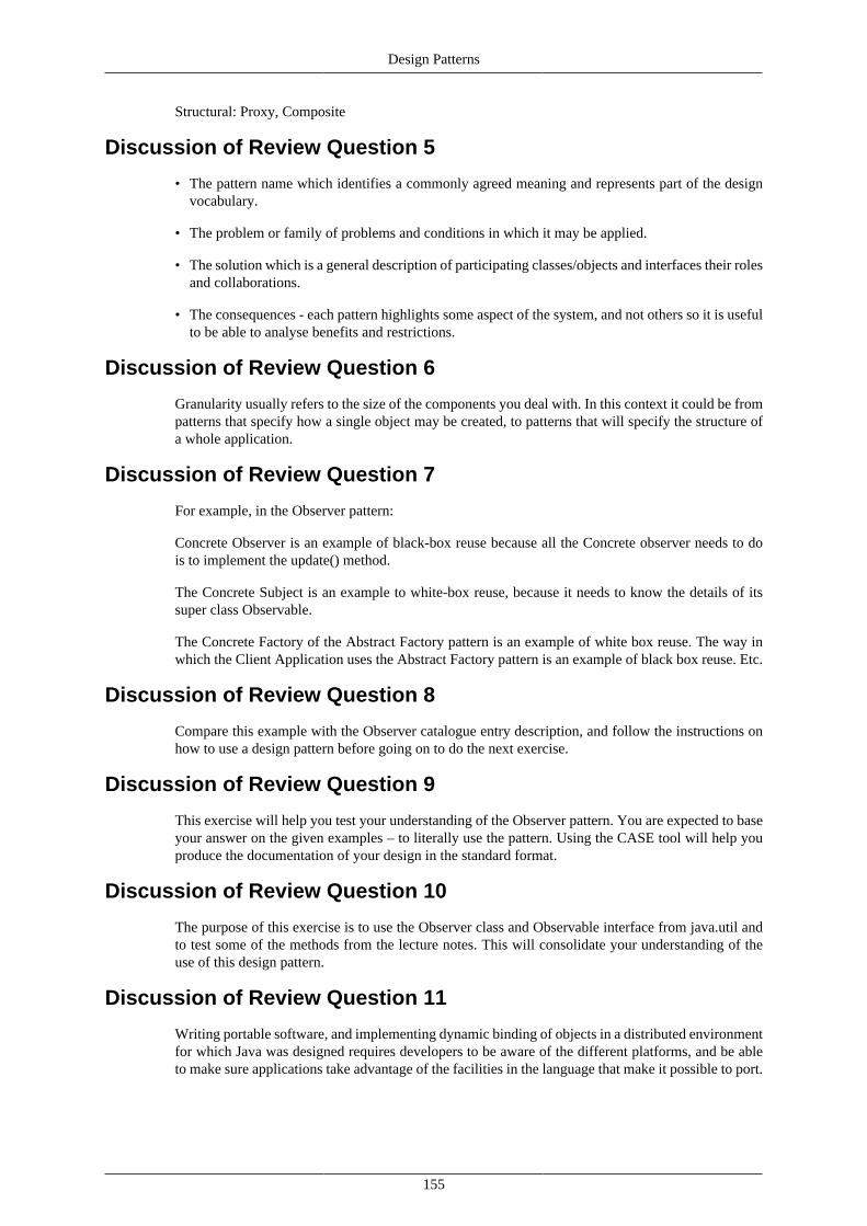
Design Patterns
155
Structural: Proxy, Composite
Discussion of Review Question 5
• The pattern name which identifies a commonly agreed meaning and represents part of the designvocabulary.
• The problem or family of problems and conditions in which it may be applied.
• The solution which is a general description of participating classes/objects and interfaces their rolesand collaborations.
• The consequences - each pattern highlights some aspect of the system, and not others so it is usefulto be able to analyse benefits and restrictions.
Discussion of Review Question 6
Granularity usually refers to the size of the components you deal with. In this context it could be frompatterns that specify how a single object may be created, to patterns that will specify the structure ofa whole application.
Discussion of Review Question 7
For example, in the Observer pattern:
Concrete Observer is an example of black-box reuse because all the Concrete observer needs to dois to implement the update() method.
The Concrete Subject is an example to white-box reuse, because it needs to know the details of itssuper class Observable.
The Concrete Factory of the Abstract Factory pattern is an example of white box reuse. The way inwhich the Client Application uses the Abstract Factory pattern is an example of black box reuse. Etc.
Discussion of Review Question 8
Compare this example with the Observer catalogue entry description, and follow the instructions onhow to use a design pattern before going on to do the next exercise.
Discussion of Review Question 9
This exercise will help you test your understanding of the Observer pattern. You are expected to baseyour answer on the given examples – to literally use the pattern. Using the CASE tool will help youproduce the documentation of your design in the standard format.
Discussion of Review Question 10
The purpose of this exercise is to use the Observer class and Observable interface from java.util andto test some of the methods from the lecture notes. This will consolidate your understanding of theuse of this design pattern.
Discussion of Review Question 11
Writing portable software, and implementing dynamic binding of objects in a distributed environmentfor which Java was designed requires developers to be aware of the different platforms, and be ableto make sure applications take advantage of the facilities in the language that make it possible to port.

156
Chapter 9. Software Testing
ObjectivesAt the end of this chapter you have gained an understanding of:
• What software bugs are.
• Who tests the software.
• How to write testable software.
• Various testing strategies, including unit testing and regression testing.
• Debugging.
Introduction to software testingSoftware never runs as we want it to: creating software is an attempt at formally specifying (usinga programming language) a solution to a problem. Assuming that it implements the correct solution(as defined by the by the various requirements and design documentation), it very often implementsthis solution incorrectly. Even if it does implement the solution correctly, the solution may itself notbe what the customer wants, or may have unforeseen consequences in the software's behaviour. In allof these situations the software may produce unexpected and unintended behaviour. The error whichcauses this unexpected and unintended behaviour is called a software bug.
Testing is the planned process of running software with the intent of discovering errors in the software.It is important to realise that testing is a purposeful process, and is not the accidental discovery ofsoftware bugs.
Discovering errors in the software implementation itself is an important aspect to software testing,but it is not the only aspect. Testing can also be used to discover how well the software conformsto the software requirements, including performance requirements, usability requirements, and soon. Understanding how to test software in a methodical manner is a fundamental skill required inengineering software of acceptable quality.
This chapter considers various aspects of software testing.
The testersMany different people involved with the development of a particular piece of software can be involvedin its testing, such as the developers, a team of independent testers, and even the customers themselves.
The developers
Testing will always begin with the developers. As they develop individual modules of the softwarethey will need to determine that what they have developed conforms with the requirements, and that itfunctions as expected. Further, the developers will have to test that these modules still function withouterror when they have been integrated with each other.
However, the developers will often test the software far more gently than is needed for proper testing,since the developers may already have pre-conceived expectations concerning how the software theyhave written behaves. Even worse, the developers may even have a vested interest in showing that

Software Testing
157
the work they have done performs correctly and meets the requirements; this works directly againstthe process of software testing.
An independent testing team
After the developer has produced working code, the code may be passed to an independent testingteam. This is a group of developers who are not responsible for the original development of thesoftware. This group's sole responsibility is to test the software that they have been given.
Independent testing teams are one solution to the problems that arise from having the originalprogrammers also test all aspects of the software. Since the testing team did not develop the software,they will hopefully have less interest in reporting that the software functions better than it does. Also,teams dedicated to testing software can use more specialised testing frameworks and methodologiesthan the developers themselves. The original programmers may not be interested in testing the usabilityof the software, or may not have the resources to examine the performance of the software; the testingteam, however, should have these resources.
The presence of testing teams does not mean that the original developers are not involved with thetesting at all. The will still test their code as they develop it, and will be involved with the testing teamas the team examines the software and reports on any errors in the software which they locate. Thedeveloper is usually the person responsible for correcting these errors.
The customer
During iterative and evolutionary development (and agile processes in general), software is frequentlygiven to the customer for them to examine, report back on, and potentially use.
When the customer is closely involved with the software development, it is possible to have thecustomer perform limited testing of the software themselves. This is known as beta testing.
While the customer will not usually be able to test the software as thoroughly as the original softwareengineers, they will be able to examine how well the software meets their needs, whether the softwarerequirements have to be changed, and whether there are any obvious bugs which the developers havemissed.
Using beta testing is not a substitute for testing by the developers.
Principles of software testing
The completion of software testing
Software testing never completes. It is an ongoing process that begins at the project's inception andcontinues until the project is no longer supported. During the software's lifetime the burden of testingslowly shifts: from the developers during design and programming, to independent testing teams, andfinally to the customers. Every action that the customer performs with the software can be considereda test of the software itself.
Unfortunately, time and money constraints often intervene: it may not be worth the developer's time ormoney to fix particular software errors. This trade-off between resources spent vs potential benefit caneasily occur for small errors, and for errors which are not often encountered by the software's users.
It is also possible (although difficult) to be statistically rigorous when discussing software errors. Forinstance, it is possible to develop a statistical model of the number of expected software failures withrespect to execution time. Error rates over a given period can then be specified given a particularprobability. When that probability is low enough, testing could be considered “complete”.

Software Testing
158
Writing testable softwareAn important aspect of testing is to ensure that the written software is written in a way that it can easilybe tested. As the software becomes more difficult to test, so the software will be tested less often.
There are a number of guidelines that software engineers can follow in order to write software thatcan be easily tested. The design principles mentioned in Chapter 7, Design, are a good place to start.In addition to this, here are some further guidelines:
• Operability: This is partly a self-fulfilling quality: the fewer bugs that a software system has, theeasier the software will be to test, since the testing will not progress erratically while time is takento repair bugs. Clearly, the more care is taken during software development to produce bug-freecode, the easier the testing that follows will be.
• Observability: Software tests examine the outputs produced by the software for particular inputs.This means that software is easier to test if the inputs produce distinct, predictable outputs. Further,it can be helpful to be able to examine the software's internal state, especially where there may beno predictable outputs, and especially when an error has been discovered.
• Controllability: As just mentioned, software testing involves examining outputs for given inputs.This means that the more easily we can provide inputs to the software, the more easily we can testthe software. This implies that software is more testable when the tester has the ability to easilycontrol the software in order to provide the test inputs. This controllability applies to the tests aswell: tests should be easily specifiable, automated, and reproducible.
• Decomposability: When software can be decomposed into independent modules, these modulescan be tested individually. When an error occurs in an individual module, the error is less likely torequire changes to be made in other modules, or for the tester to even examine multiple modules.
• Simplicity: Clearly, the simpler the software, the fewer errors it will have, and the easier it will beto test. There are three forms of simplicity that software can demonstrate: functional simplicity, inwhich the software does no more than is needed of it; structural simplicity, in which the softwareis decomposed into small, simple units; and code simplicity, in which the coding standards used bethe software team allows for the easy understanding of the code.
• Stability: If changes need to be made to the software, then testing becomes easier if these changesare always contained within independent modules (via, for instance, decomposability), meaningthat the code that needs to be tested remains small.
• Understandability: Clearly, the more the testers understand the software, the easier it is to test.Much of this relates to good software design, but also to the engineering culture of the developers:communication between designers, developers and testers whenever changes occur in the softwareis important, as is the ability for the testers and developers to easily access good technicaldocumentation related to the software (such as APIs for the libraries being used and the softwareitself).
Test cases and test case designTest cases are controlled tests of a particular aspect of the software. The objective of a test case is touncover a particular error. Testing software, then, is the development of a suite of such test cases, andthen their application to the software.
Tests should be kept simple, testing for specific errors (or specific classes of errors) rather than testingwhole branches of the software's functionality at a time. In this way, if a test fails the failure will pointto a particular area of the software that is at fault.
Testing strategiesJust as it is important to develop software in a way that eases software testing, it is also important toboth design tests well, and to have a good strategy as to how the software should be tested.

Software Testing
159
Testing is incremental: it begins by testing small, self-contained units and progresses to testing theseunits as they interact with each other. Ultimately, the software as a whole — with all units integrated— is tested.
Testing can be broken down into the following stages: unit testing (testing individual modules),integration testing (testing modules as they are brought together), validation testing (testing to seeif the software meets its requirements), and system testing (testing to see how well the softwareintegrates with the various systems and processes used by the customer).
Unit testingUnit testing is concerned with testing the smallest modules of the software. For each module, themodule's interface is examined to ensure that information properly flows to and from the module. Thedata structures which are internal to the module should be examined to ensure that they remain in aconsistent state as the module is used. The independent paths (see the section called “ Flow graphs,cyclomatic complexity and white-box testing ” in this chapter) through the module should each betested. Boundary conditions should also be closely examined to ensure that they are properly handled(such as, for example, not reading past the end of an array). Importantly, remember to test the errorhandling code and ensure that they handle and report errors correctly.
Unit tests can easily be incorporated into the development process itself: unit tests can be written whileeach module is written. Indeed, some software design methods (such as extreme programming, seeChapter 2, Process and Model) ask for unit tests to be developed before the software itself. Regressiontests (a form of integration testing), too, can be incorporated into the development process — one wayof doing so is to have them automatically run each night, after all code developed that day has beensubmitted to a central repository.
Integration testingOnce unit testing is complete, the next important step is to combine the separate modules and ensurethat they function correctly together. One may think that because each module functions correctly byitself that they will function correctly together. This is not always the case. For example, module Amight have certain expectations about the behaviour of module B that are not being met, causing Ato function incorrectly.
It may seem that integration testing can be carried out by combining all modules at once and testinghow they function. Unfortunately, this “big bang” approach can make it difficult to track an error downto any one particular module. A better approach is to combine modules together incrementally, testingtheir behaviour at every step. Each increment brings us closer to having the complete software, buteach increment remains constrained enough for us to properly test.
There are two general methods for performing module integration: the top-down and bottom-upapproaches. Top-down integration testing begins by creating the overall software where much of itsfunctionality is provided by empty stub modules. These modules perform no function other than toallow the software to compile, and to provide a way to exercise the modules which are being tested. Thestubs are then replaced with the actual modules, one at a time, beginning with the modules involvedwith user-interaction and ending with the modules which perform the software's functionality. As eachmodule passes its tests, a new module is integrated.
Clearly, top-down integration is difficult because of the need to create stub modules. The proper testingof some modules may rely upon a wide range of behaviour from the sub-modules, and so either thetesting must be delayed until the stubs have been replaced, or the stubs must offer much functionalitythemselves (and may themselves be buggy).
The alternative to the top-down approach is bottom-up integration testing: here, modules whichdo not rely on other modules are combined together to create the software. Because we begin withmodules that do not rely on other modules, no stub code is needed at all. At each step we test thecombined software. When all tests have passed we add another module together. Ultimately, all themodules will be combined into the functioning software.

Software Testing
160
Whether a top-down approach, a bottom-up approach, or a mixture of both approaches, is used,whenever a new module is added to the software in order to be tested, the whole software has changed.Modules which rely on the new modules may behave differently, and so once again allthe moduleshave to be tested. Regression testing is the testing of the previously tested modules when a newmodule is added. Regression testing should occur at every incremental step of the integration testingprocess.
Validation testingUnit and integration testing asks the question, “Are we developing the software correctly?” Validationtesting, on the other hand, asks, “Are we developing the correct software?” In other words, validationtesting is concerned with whether the software meets its requirements.
Validation testing focuses on the user-visible portions of the software, such as the user-visible inputsand outputs, and the software's actions. The tests examine these user-visible portions to ensure thatthey meet the software requirements. While not part of the software itself, the documentation shouldalso be examined to ensure that they meet any requirements concerning them.
We have previously mentioned beta testing as the process of the customers themselves testing thesoftware. This can be a useful tool in the validation testing process, since the developers cannot foreseeexactly how the customers may use the software.
System testingSoftware is always employed within some larger context, such as all the systems and processes whicha business customer may have in place. System testing is concerned with how the software behavesas it integrates into the broader system in which it will be used.
For example, when the software fails or suffers from an error it must not cause the whole system thatis using it to fail. Recovery testing examines how the software behaves when it fails. Security testingexamines how well the software protects sensitive information and functionality from unauthorisedaccess. Stress testing examines how the software functions under an abnormal load. While softwaremay perform well by itself, its behaviour can be quite different when its used in a larger setting;performance testing examines the software's performance within the context of the system as a whole.
Testing adviceWhile the previous sections have mostly given advice and guidelines on designing the overall testingstrategy, in this section we discuss more concrete advice on creating individual tests, with a focus ontesting for implementation bugs (i.e., unit and integration testing) rather than validation and systemtesting.
An initial distinction to be made when creating a test is the difference between white-box and black-box testing. Black-box testing treats the module as an object whose inner-workings are unknowable,except for how the module handles its inputs and outputs. Black-box testing does not examine themodule's inner state, and assumes that if the module correctly handles its inputs and outputs, then it iserror free. White-box testing, on the other hand, also examines the module's inner state in an attemptto ensure that its internal operations are correctly performed, no matter how the module handles itsinputs and outputs.
White-box testing allows us to conceivably test every line of code in the module: since we areexamining the software's internal state, we can determine where and how that state changes, and soconstruct tests to exercise not only every line of code, but every logical choice that can be madewhen executing the code. This process of testing all lines of code and all logical choices in a softwaremodule is called exhaustive testing, and it is extremely important to realise that, except in the mosttrivial of cases, exhaustive testing is impractical to perform. To see this, one need only consider thatwhenever the software contains, for example, if statements within if statements, or loops within loops,

Software Testing
161
the number of logical paths through the software increases exponentially, and so does the time requiredto test each of these choices. Even software of only a few hundred lines of code can quickly requiremore time than is feasible to test every logical decision that could possibly be made by the software.How this exponential explosion of choice is to be handled is an important aspect of white-box testing.
Flow graphs, cyclomatic complexity and white-boxtesting
It will be useful to introduce some simple graphical notation for representing the execution flow of aprogram. While testing can (and often is) discussed without mention of flow graphs, they do providea graphical tool for better describing the various testing processes.
Figure 9.1, “Flow graph notation”, displays various examples from the notation. The nodes in thegraph represent some unit of processing that must occur. All logical decisions which affect the flowof program execution are represented by the edges in a graph: when an if statement decides on whichbranch to take (its then or else branches), this is represented by multiple edges leading to separatenodes. Similarly, various loops, case statements, and so on, are represented in a similar way.
An independent path through a program is a path through a flow graph which covers at least oneedge that no other path covers. Examine Figure 9.2, “An example flow-graph”. The paths 1,2,3,5,7,8and 1,2,3,5,7,5,7,5,7,8 are not independent, because neither of them have an edge which the other doesnot. However, the paths 1,2,3,5,7,8 and 1,2,4,6,8 are independent.
The set of all independent paths through a flow graph make up the basis set for the flow graph. If ourtesting can execute every path in the basis set, then we know that we have executed every statementin the program at least once, and that we have tested every condition as well.
Note
While we may have tested every line of code, and every condition, we have still nottested every possible combination of logical choices that could be made by the conditionalstatements during software execution. In this way we limit the explosion of test cases theexhaustive testing would produce. However, this does mean that some bugs may still escapedetection.
The cyclomatic complexity of a flow graph informs us how many paths there are in the graph's basisset (in other words, how many independent paths there are needing to be tested). There are three waysin which it can be computed:
• By counting the number of regions in the flow graph.
• If E is the number of edges in the flow graph, and N the number of nodes, then the cyclomaticcomplexity is: E - N + 2.
• The cyclomatic complexity is also P + 1, where P is the number of nodes from which two or moreedges exit. These are the nodes at which logical decisions controlling program flow are made.
In Figure 9.2, “An example flow-graph”, we can calculate the complexity in all three ways. There arefour regions in the graph (remember to count the space surrounding the graph, and not only the spacesinside the graph). There are ten edges and eight nodes. There are three nodes from which two or moreedges leave. Using the three methods above, we get:
• Four regions give a cyclomatic complexity of 4.
• Ten edges and eight nodes give a cyclomatic complexity of 10 - 8 + 2 = 4
• Three nodes with two or more exiting edges gives a cyclomatic complexity of 3 + 1 = 4

Software Testing
162
Figure 9.1. Flow graph notation
A sequence flow graph
An if statement flow graph
A case statement flow graph
An until statement flow graph

Software Testing
163
Figure 9.2. An example flow-graph
An example flow graph, with labeled nodes. Execution begins at node 1, and proceedsthrough an if statement, and possibly through a loop. Execution terminates at node 8.
As we can see, each method agrees with each other, and states that there are four independent pathsthrough the program.
The third definition has broad applicability, since it provides a method for calculating complexitywithout using flow graphs: one can merely count the number of conditional statements in a programand add one to this number.
These concepts of independent paths, basis sets and cyclomatic complexity are important to testing,because they give us a concept of how well our tests may be exercising the code. Importantly, thoseportions of the code which are used least are the portions which are the least likely to be tested, and themost likely to retain their errors. Discovering the independent paths through a program, and testingthem all, allows us to ensure that these errors do not go unchecked. Various studies have also shownthat the higher the cyclomatic complexity of a given package, the more likely it is to have errors.
We want to again point out that testing all independent paths is not the same as exhaustive testing.Exhaustive testing wishes to test all possible paths through the flow graph, as determined by examiningall possible combinations of logical choices that could occur at the conditions. In the particular exampleused here, the number of all paths through the program depends on the number of times that the loopneeds to iterate. If the loop were to contain other loops, or if statements, this number of paths wouldincrease dramatically. The use of independent paths keeps the number of tests to a reasonable level,while ensuring that all lines of code are tested.
The testing methodology which tests all independent paths through an application is called basis pathtesting, and is clearly a white-box testing method.
Basis path testing can be tedious to perform. It does provide suggestions for determining tests ingeneral, however. When determining how to test code, always test the logical conditions (this is calledcondition testing). Also, focus on the conditions and validity of loop constructs (loop testing).

Software Testing
164
Black-box testingWhile white-box testing is interested in how the module performs its function, black-box testing isinterested only in what the module should be doing. Black-box testing tests the requirements of thesoftware module, and not at all with how it manages to meet these requirements.
These requirements cover a wide range of areas to be tested, and includes:
• Input and output errors, which includes not only errors which may occur when making use of thesoftware module, but also errors that may occur when the software module attempts to use othermodules, such as a database.
• Incorrect and missing functions.
• Initialisation and termination errors.
• Behaviour errors.
• Performance errors.
• Reliability errors.
We will examine two methods of black-box testing: equivalence partitioning and boundary valueanalysis.
Equivalence partitioning
Equivalence partitioning divides a software module's input data into equivalence classes (note thatthese are not classes in the sense of object-oriented programming). The test cases are then designedso as to test each one of these input classes; a good test case will potentially discover errors in wholeclasses of input data.
Generally, for any input, we will have at least two classes. For example, if the input to the softwareis a Boolean, then this is clearly the case (in this case, each class has one value: one true, the otherfalse). Similarly, if the input is a member of a set, then you will have multiple classes. For example, ifwe had a software module from a graphics package which, when given a rectangle, used the lengthsof its sides to determine whether the rectangle was a square or not, then we would have two classes:one for the rectangles which are square, one for rectangles which are not.
The number of classes strongly depends on the type of the input data. If the input data requires aspecific number, then there are three classes: one for that number, one for all numbers less than it,and one for all numbers greater than it. Similarly, if the input should be from a range of numbers, weagain have three classes.
Testing each input class reveals whether the software module correctly handles the range of input thatit could receive.
Boundary value analysis
Software bugs tend to occur more frequently at their “boundary values”, which are those values aroundwhich a conditional changes the value it evaluates to. For instance, boundary values are those valuesfor which an if statement will change between choosing to execute its then or else portions, or wherea loop decides whether to iterate or not.
This increase in errors can occur for simple reasons, such as using a greater-than comparison instead ofa greater-than-or-equal-to comparison. When looping, common boundary mistakes include iteratingone time too many, or one time too few.
Because of the increased frequency with which errors occur around boundary values, it is important todesign test cases that properly exercise the boundaries of each conditional statement. These boundaries

Software Testing
165
will occur between the various input classes in the equivalence partitioning method, and so boundaryvalue analysis is well suited to being combined with that method.
Object-oriented testingTesting methodologies can be modified slightly when the software is developed in an object-orientedmanner.
The basic “unit” for unit testing becomes the class as a whole. This does have the consequence,however, that the various methods cannot be tested in isolation, but must be tested together. At thevery least the class's constructor and destructor will always be tested with any given method.
Similarly, when performing integration testing, the class becomes the basic module which makesup the software. Use-based is a bottom-up integration method constructing the software from thoseclasses which use no other, then integrating these with the classes which use them in turn, and soon. Classes can also be integrated by following program execution, integrating those classes that arerequired in order to respond to particular input (thread-based testing), or, similarly, to integrate thoseclasses which provide some specific functionality, independent of the input to the software (clustertesting).
In general, you should not only test base-classes, but all derived classes as well. Inheritance is a specialcase of module integration, and should be treated as such.
DebuggingOnce a test case has been executed and a bug located, debugging begins. Debugging is the process oflocating the cause of a software error and correcting it. Unfortunately, this is not necessarily an easyprocess. Software engineers are only ever presented with the software's behaviour, and they do notdirectly see the error's cause. Debugging, then, relies on the software engineer to determine from thesoftware's incorrect behaviour the causes of this behaviour.
Debugging begins with the software failing a test case. The software engineer debugging the softwarewill then hypothesise a possible cause and implement the needed changes to correct this in the software.The failed test is then rerun. Further test cases may also be written to help narrow down the actualcause. This all occurs iteratively, with each step hopefully providing more information to the developeras to the root cause of the error.
A number of debugging tactics have been proposed. They can be used alone, although they becomefar more effective when used in combination with each other.
Brute force debuggingThis is conceptually the simplest of the methods, and often the least successful. This involves thedeveloper manually searching through stack-traces, memory-dumps, log files, and so on, for traces ofthe error. Extra output statements, in addition to break points, are often added to the code in order toexamine what the software is doing at every step.
BacktrackingThis method has the developer begin with the code that immediately produces the observable error.The developer than backtracks through the execution path, looking for the cause. Unfortunately, thenumber of execution paths which lead to any given point in the software can become quite large thefurther the cause of the bug is from where the error occurs, and so this method can become impractical.
Cause eliminationIn this method, the developer develops hypotheses as to why the bug has occurred. The code can eitherbe directly examined for the bug, or data to test the hypothesis can be constructed. This method can

Software Testing
166
often result in the shortest debug times, although it does rely on the developers understanding thesoftware well.
BisectBisect is a useful method for locating bugs which are new to the software. Previous versions of thesoftware are examined until a version which does not have the error is located. The difference betweenthat version's source code and the next is then examined to find the bug.
Review
Questions
Review Question 1
Complete:
Testing is the [________] process of running software in with the intent of [______________] in thesoftware. It is important to realise that testing is a [__________] process, and is not the accidentaldiscovery of software bugs.
A discussion of this question can be found at the end of this chapter.
Review Question 2
Who are the different parties involved in software testing, and how does the testing shift from oneparty to another?
A discussion of this question can be found at the end of this chapter.
Review Question 3
What guidelines would you give for developing software that is easily testable?
A discussion of this question can be found at the end of this chapter.
Review Question 4
Complete:
Test cases are controlled tests of [__________________] of the software. The objective of a test caseis [_____________]. Testing software, then, is the development of [___________________], and thentheir application to the software.
A discussion of this question can be found at the end of this chapter.
Review Question 5
What are the different stages of software testing?
A discussion of this question can be found at the end of this chapter.
Review Question 6
What is the difference between white-box and black-box testing?
A discussion of this question can be found at the end of this chapter.

Software Testing
167
Review Question 7
Why is it not practically possible to test every logical path through a piece of software? Whatalternatives are there?
A discussion of this question can be found at the end of this chapter.
Review Question 8
Debugging begins with the software [_________] a test case. The software engineer debugging thesoftware will then [_____________] a possible cause and [___________________] in the software.The failed test is then rerun. This might not always provide an exact reason for the bug, and so furthertest cases may also be written to [_______________________]. This all occurs iteratively, with eachstep hopefully providing more information to the developer as to the root cause of the error.
A discussion of this question can be found at the end of this chapter.
Review Question 9
What are some common debugging techniques?
A discussion of this question can be found at the end of this chapter.
Answers
Discussion of Review Question 1
Testing is the planned process of running software in with the intent of discovering errors in thesoftware. It is important to realise that testing is a purposeful process, and is not the accidentaldiscovery of software bugs.
Discussion of Review Question 2
There are three parties involved in software testing:
1. The developers
2. Independent testers
3. The customers / users
Testing originally begins with the developers, who need to ensure that the software they have codedworks as they intend. Testing is then taken over by independent testers, who are able to use morespecialised testing frameworks than the developers themselves. They can also perform user-basedtesting, which most developers would not be able to do.
Finally, as the software is delivered to the customer and the software begins to be used, its usersbecome the final group of testers.
Discussion of Review Question 3
• Operability. New code developed for relatively bug-free software will have fewer bugs than codedeveloped for relatively buggy software.
• Observability. Software whose internal state can easily be examined, and that produces well definedoutputs for particular inputs, is easier to test.
• Controllability. If the tester has the ability to easily control the software, testing becomes easier:controllability allows for the easier inputting of data and examining of output.

Software Testing
168
• Decomposability. Independent modules can more easily be tested, and changes made to a moduleare less likely to affect other modules.
• Simplicity. The simpler the software, the fewer errors it will have.
• Stability. Testing is easier if changes made to correct bugs are limited to independent modules.
• Understandability. The better the testers understand the software — through good software design,documentation, and so on — the better they can test the software.
Discussion of Review Question 4
Test cases are controlled tests of particular aspects of the software. The objective of a test case isuncover a particular error. Testing software, then, is the development of a collection of test cases,and then their application to the software.
Discussion of Review Question 5
• Unit testing, which tests the smallest modules of the software.
• Integration testing, which tests the software as the modules are brought together.
• Validation testing, which tests the software to ensure that it meets its requirements specification.
• System testing, which examines how well the software integrates with the various systems andprocesses used by the customer.
Discussion of Review Question 6
Black-box testing tests the module as an object whose inner-workings are unknowable, except for howit handles its inputs and outputs. Black-box testing therefor does not examine a module's inner state,only the interfaces to the module. It assumes that if it handles its inputs and outputs correctly, thenthe module itself behaves correctly.
White-box testing examines the software's internal state; it does not assume that because a modulehas handles its inputs and outputs correctly that the module has behaved correctly. For example, aftercorrectly outputting some data, a module may leave its internal state with invalid values, and so anyfurther action will fail.
Discussion of Review Question 7
The number of possible logical paths through a piece of software can grow exponentially as ifstatements and loops are added. This would make the amount of time required to test a large softwarepackage prohibitive.
An alternative testing strategy is to determine the software's cyclomatic complexity, which tells us howmany independent paths there are through the software. Each of these independent paths can then betested; this will provide good code coverage (it will execute every line of code) without exhaustivelytesting every logical path through the software, and so greatly reduces the amount of time needed toexecute the software.
Discussion of Review Question 8
Debugging begins with the software failing a test case. The software engineer debugging the softwarewill then hypothesise a possible cause and implement the needed changes in the software. The failedtest is then rerun. This might not always provide an exact reason for the bug, and so further test casesmay also be written to narrow down the cause. This all occurs iteratively, with each step hopefullyproviding more information to the developer as to the root cause of the error.

Software Testing
169
Discussion of Review Question 9
• Brute force debugging; the developer searches through stack-traces, memory-dumps, log files, andother data generated by the program to locate the error.
• Backtracking; the developer examines the code that immediately produces the observable bug, andthen moves backwards through the execution path until the cause of the bug has been found.
• Cause elimination; the developer hypothesises reasons why the bug has occurred, and then eitherdirectly examines the code to see if these reasons exist, or produces further tests to narrow downthe choice between various hypotheses.
• Bisect; the developer examines previous versions of the software until one without the bug is located.The difference between that version of the source code and the next (in which the bug does notexist) is where the bug will be located.