software collaboration foundation operational concept
TRANSCRIPT

SOFTWARE COLLABORATION FOUNDATION OPERATIONAL CONCEPT
DOCUMENT (OCD)
BENJAMIN KRAINES SYRACUSE UNIVERSITY
SMA681 Project 5
DECEMBER 7, 2016

1
Table of Contents 1 Introduction .......................................................................................................................................... 3
2 Executive Summary ............................................................................................................................... 3
- A simple messaging framework will be defined to pass information seamlessly between top level
applications in the remote harness. ............................................................................................................. 4
- A core set of services will be provided to each SCF module via the SCFCore....................................... 4
- Top Level applications are the following: ............................................................................................. 4
o Client ..................................................................................................................................................... 4
o Virtual Display Client ............................................................................................................................. 4
o Repository ............................................................................................................................................. 4
o Test Harness .......................................................................................................................................... 4
o Collaboration Server ............................................................................................................................. 4
- Seamless video streaming was shown possible in the .NET framework in the “VideoPrototype”
demonstration .............................................................................................................................................. 4
- Resource Disposal mechanics were shown enforceable in the “ResourceControl” demonstration .... 4
3 Guiding Principles .................................................................................................................................. 4
3.1 Agile Process.................................................................................................................................. 4
3.2 Concurrent Testing ........................................................................................................................ 4
3.3 Eating Your Own Dogfood ............................................................................................................. 4
4 Federation Level Overview ................................................................................................................... 5
4.1 Concept ......................................................................................................................................... 5
4.2 Uses and Users .............................................................................................................................. 5
4.2.1 Developer .............................................................................................................................. 5
4.2.2 Quality Assurance ................................................................................................................. 6
4.2.3 Managers .............................................................................................................................. 6
4.2.4 SCF Servers/Clients ............................................................................................................... 6
4.3 Structure ....................................................................................................................................... 6
4.4 Activities ........................................................................................................................................ 8
4.5 Critical Issues ................................................................................................................................. 8
4.5.1 Scaling/Performance ............................................................................................................. 8
4.5.2 Security ................................................................................................................................. 8
4.5.3 Process Flow Management ................................................................................................... 9
4.5.4 Error Handling ....................................................................................................................... 9

2
4.5.5 Code Prototypes .................................................................................................................... 9
4.6 Future Uses ................................................................................................................................... 9
4.6.1 Repository/Build Generality .................................................................................................. 9
5 Structure/Subcomponent Concepts ................................................................................................... 10
5.1 SCF Core ...................................................................................................................................... 10
5.1.1 Concept ............................................................................................................................... 10
5.1.2 Uses and Users .................................................................................................................... 10
5.1.3 Structure ............................................................................................................................. 10
5.1.4 Activities .............................................................................................................................. 11
5.1.5 Critical Issues ....................................................................................................................... 11
5.2 Repository ................................................................................................................................... 13
5.2.1 Concept ............................................................................................................................... 13
5.2.2 Uses and Users .................................................................................................................... 13
5.2.3 Structure ............................................................................................................................. 13
5.2.4 Activities .............................................................................................................................. 15
5.2.5 Critical Issues ....................................................................................................................... 17
5.3 Build Server ................................................................................................................................. 18
5.3.1 Concept ............................................................................................................................... 18
5.3.2 Uses and Users .................................................................................................................... 18
5.3.3 Structure ............................................................................................................................. 18
5.3.4 Activities .............................................................................................................................. 19
5.3.5 Critical Issues ....................................................................................................................... 19
5.4 Test Harness ................................................................................................................................ 20
5.4.1 Concept ............................................................................................................................... 20
5.4.2 Uses and Users .................................................................................................................... 20
5.4.3 Structure ............................................................................................................................. 20
5.4.4 Activities .............................................................................................................................. 22
5.4.5 Critical Issues ....................................................................................................................... 23
5.5 Client ........................................................................................................................................... 24
5.5.1 Concept ............................................................................................................................... 24
5.5.2 Uses and Users .................................................................................................................... 24
5.5.3 Structure ............................................................................................................................. 24
5.5.4 Activities/Interface .............................................................................................................. 25

3
5.5.5 Critical Issues ....................................................................................................................... 28
5.6 Virtual Display Client ................................................................................................................... 29
5.6.1 Concept ............................................................................................................................... 29
5.6.2 Uses and Users .................................................................................................................... 29
5.6.3 Structure ............................................................................................................................. 29
5.6.4 Activities .............................................................................................................................. 31
5.6.5 Critical Issues ....................................................................................................................... 32
5.7 Virtual Display Server .................................................................................................................. 32
5.7.1 Concept ............................................................................................................................... 32
5.7.2 Uses and Users .................................................................................................................... 32
5.7.3 Structure ............................................................................................................................. 32
5.7.4 Activities .............................................................................................................................. 33
5.7.5 Critical Issues ....................................................................................................................... 34
5.8 Communication Architecture ...................................................................................................... 34
5.8.1 Concept ............................................................................................................................... 34
5.8.2 Structure ............................................................................................................................. 34
6 Conclusion ........................................................................................................................................... 36
1 Introduction The following is an Operational Concept Document describing the basis for development on a
comprehensive automated remote test harness. The executive summary will provide you with the key
takeaways from initial prototyping and architecture work, and the path moving forward. Beyond that,
the document delves into the specific system design elements and details which will guide project
execution. If you have any questions, comments, or concerns regarding this document, please contact
the author Ben Kraines via email at [email protected].
Administrative Note: Differences in diagram formatting between visio/gliffy only reflects the fact that
gliffy was used for this OCD, but visio was used in some legacy OCD’s on similar topics, which have been
incorporated – no content was pulled from illegitimate sources.
2 Executive Summary In general, the Software Collaboration Foundation concept was found to be viable and ready for
transition into the implementation phase. The following are the key takeaways from this document:

4
- A simple messaging framework will be defined to pass information seamlessly between top
level applications in the remote harness. - A core set of services will be provided to each SCF module via the SCFCore - Top Level applications are the following:
o Client o Virtual Display Client o Repository o Test Harness o Collaboration Server
- Seamless video streaming was shown possible in the .NET framework in the “VideoPrototype”
demonstration - Resource Disposal mechanics were shown enforceable in the “ResourceControl” demonstration
The Software Collaboration Foundation (SCF) is realistic, and ready to be implemented! This document
has laid out the path forward in detail towards a complete application.
3 Guiding Principles Several guiding principles in the architecture and development process are important to the successful
and expedient implementation of the designs laid out in this document. Each one is listed below and
briefly described.
3.1 Agile Process Agile software development is one of the prevailing schools of thought in industry regarding
evolutionary and responsive software design. Although the development of this test harness won’t be
completed in a team, there are many key lessons in the agile manifesto that can be mapped onto this
effort. Small iterative cycles are key to a responsive and effective development process. As each package
in the framework is built, these mini cycles are an absolute must. The development must be sustainable,
and well thought-out. The remote test harness will be used later in the larger project five continuous
integration application federation, so it is very important that the design is future-proofed. On the
whole, agile provides a set of principles that are highly useful to developers, and those should be rightly
applied in this work.
3.2 Concurrent Testing Testing during the execution of the “mini cycles” discussed above is crucial to making consistent
progress on the federation. Construction tests shall be used while writing packages to confirm
functionality after each small addition. These must occur along the way – otherwise risk is incurred by
adding large untested pieces of code with many potential modes of failure.
3.3 Eating Your Own Dogfood As development continues on the CI framework – the framework itself should start being used to test
new packages once it reaches a minimum viable condition! There’s no better way to validate usability
and functionality than being required to use the product in its own development. This practice is dubbed

5
“eating your own dogfood” in industry. You can bet that the developers of Visual Studio are using it as
their development environment, and the same principle applies here.
4 Federation Level Overview
4.1 Concept The Software Collaboration Federation (SCF) is a collection of clients and servers which work in unison to
provide a set of critical software development capabilities in support of a large international software
development business model. The underlying motivator baked into the design and functionality of this
system is the need for collaborative workflow in the software business. In an organization with hundreds
of developers around the globe, a system for continuously integrating changes in the baseline is an
absolute must. The ultimate deliverables from the SCF are viable software products. As such, the SCF
will facilitate development, and disclose the status of the baseline to the company. The architecture
outlined in this document strives to meet this concept.
4.2 Uses and Users Keeping in mind the concept for the SCF discussed above, the Uses and Users section will delve into the
specific functional roles the SCF plays with respect to people and systems within the company. Note that
this federation level will cover most of the users and uses, but that more detail may be provided in the
subsystems sections, especially with other services as users.
4.2.1 Developer Developers will be the most prolific users of the SCF. Every day, they will be booting up the client at their
desk and using nearly every aspect of the system. The main uses of the SCF by developers are the
following:
- Checking out code
- Checking in code
- Submitting Test Requests
- Viewing Test Results
- Uploading/Downloading Design documents
- Video Display sessions with employees anywhere in the world
Control Inputs: Each of the uses listed above needs an easy to use interface for the developer in a client
on their desktop. Developers should be able to quickly and seamlessly switch between the different
functional controls easily, with buttons for triggering each critical action that interacts with the SCF.
Design Implications: The diversity of input required for the developers to access the SCF’s services
makes a tabbed graphical interface a good choice when building a client application for them. A
possible layout would have code/test items on one tab, program management & file exchange work on
another tab, and a virtual display window in the third tab to allow direct collaboration with developer
around the world.

6
4.2.2 Quality Assurance Quality Assurance(QA) personnel serve a critical role in the higher-level baseline health management for
the company’s software products, using the SCF for the following tasks:
- Submitting Test Requests
- Viewing Test Results
- Scheduling Tests/Builds
- Configuration management for release/versioning
- View baseline status info
- Video Display sessions with employees anywhere in the world
Control Inputs: Each of the uses listed above needs an easy to use interface for the QA engineer in a
client on their desktop. QA should be able to quickly and seamlessly switch between the different
functional controls easily, with buttons for triggering each critical action that interacts with the SCF.
Design Implications: The clients for developers should likely populate differently than that of QA
personnel. The basic tabbed structure might remain the same, but the content/interface would be
customized to fit the tasks listed above. Within the repository/test harness, QA tasks must be scheduled,
implying that a scheduler module which can trigger events as specified must be implemented.
Additionally, dependent code gathering should be automatically managed within the repository. The
tests run by the QA personnel will involve large baselines, so the system needs to be as efficient as
possible and have scalability options available for growing baselines.
4.2.3 Managers Managers will generally use the SCF in project management contexts, in the following ways:
- Uploading/Downloading Design documents
- Video Display sessions with employees anywhere in the world
- View high level baseline status info
Control Inputs: Design document and video session tasks need an easy to use interface for the manager
to interact with in a client on their desktop. For the high-level baseline info, managers should be able to
subscribe to whatever update frequency they would like, and receive an automated message in the
client with those results.
Design Implications: Much of the video chat and design document exchange functionality can be
implemented in a trimmed down version of the QA/dev client. Scheduling for the baseline info means
event schedulers must exist in the SCF and allow varying subscription frequencies to push to the
manager clients.
4.2.4 SCF Servers/Clients The server and client modules within the SCF are themselves users of one another. Without delving too
deeply into the communication architecture, which will be discussed in depth later in the OCD, their use
of one another requires uniformity in communication protocol and message structure. Error handling
can’t interrupt the process flow occurring between these modules.
4.3 Structure The overall SCF is divided into five different functional executables:

7
1. Repository Server: Dependency organized storage for code and documents.
2. Build Server: Subordinate process of repository for building configured baseline executables.
3. Test Harness: Test server which runs tests on code from the repository.
4. Client: User portal into the SCF providing interface to each service.
5. Collaboration Server: Server to store project management information, work packages, design
documents, etc.
6. Virtual Display Client: Provides the user with video/collaborative interaction options between their
SCF client and others via the Virtual Display server.
7. Virtual Display Server: Manages virtual display sessions between users.
The interactions between these elements are defined at a high level in the machine interaction diagram
below:
Figure 1: Software Collaboration Foundation Structure
Any place where arrows connect modules indicate communication channels, and modules on a corner
are housed on the same machine as the larger module (display client and build server). Communication

8
channels can connect users over any distance, making the placement of these machines geographically
agnostic. It is important to note that each of these services will share a common core of functionality,
that each module will be built upon. Examples of common SCF core functions are communication, file
management, message passing. These core functions, as well as the design of each module will be
discussed in the structure/subcomponents section later in the OCD.
4.4 Activities At the federation level, there are several important meta-activities that the SCF serves to perform.
- Version Code: Keep track of new changes in the code and provide a trail of previous versions to
error correct and mark as specific builds of the software.
- Test Code: Use a test harness to automate testing of individual components or large swaths of
the baseline, as company needs dictate.
- Build Code: Automate the process of building code completely in the SCF.
- Facilitate Collaboration: Provide a platform for developers to work together across the globe
relatively seamlessly.
- Monitor Baseline: Show percentage of passing tests, recent builds, names of key releases, etc.
These top-level goals will be granularized in the subsystem sections to delve into how each SCF service
contributes to the big picture.
4.5 Critical Issues The following critical issues are implementation concerns moving forward to development of the SCF.
For each issue a description and solution is provided.
4.5.1 Scaling/Performance Description: As the baseline expands, and testing loads begin to exceed the performance capability of a
single test harness, the issue of scaling out comes into play. Extending the test harness needs to be easy
when scaling becomes necessary.
Solution: Whenever any client first attempts to connect to another service (test harness, repository,
collab server) it will use a single url, which accesses a small reference service that sends the client a
message listing all available servers of the requested type, and their urls. Then the client will select the
server they want to connect to, and use that url from the response directly to communicate with it. If
the client needs to switch to another server later, it can just send another request to the reference
service’s known url and receive the updated list for selection. The structure of the reference service
could essentially be a thread sending small acknowledgement requests to the list of all known servers
online every so often. This list would need to be maintained by IT personnel as they add servers during
scaling. If a server fails to reply for a given amount of time, this server is assumed offline and will not be
served to clients requesting a url.
4.5.2 Security Description: Development must consider the security aspect of the communication links in between the
servers and clients in the system. Since the codebase is proprietary, and the SCF services will be directly
handing this data, outside access must not be allowed.

9
Solution: This issue mostly affects the machine assignment/scaling aspect of the SCF architecture.
Bottom line, these servers should be operating within an authenticated corporate network to ensure
connections are coming from actual employees. Tools like VPN into the corporate network could be
used to access the SCF resources from outside a company office.
4.5.3 Process Flow Management Description: In a system as complex as the SCF, it can become difficult to keep track of everything that
is going on at once. Events are occurring at an extremely fast rate in a very distributed way, which may
lend opportunities for certain lines of processing to be lost in the confusion. If a given operation fails,
the caller may not know it failed and remain waiting for some action that will never occur.
Solution: Event handlers in every SCF service are routing messages, files, and other data via the defined
WCF channels based upon state and processing within the service. These manage the process flow
automatically. However, it is critical for services to notify other using services when something doesn’t
go as expected. For example, if the repository is checking out some code for a client, but the files don’t’
exist, it needs to send back a notification to the client so that it knows not to wait on arrival of those
files, but also to give the user situational awareness of the failure. This principle should be extended to
all process flows in the SCF architecture.
4.5.4 Error Handling Description: Uncaught errors in any of the SCF services can cause an entire piece of the architecture to
go down.
Solution: It is important to keep track of likely error triggers (e.g. File IO – in the SCFCore, Tests in the
TestHarness) and apply a mitigation technique which will deal with the error but keep the service intact.
Two examples would be:
1. A File IO polling try-catch block, which tries to access a file only if it exists, and if it cannot access it,
wait a small amount of time and try again to dodge concurrent file access issues.
2. Implementing error-prone functionality in a sequestered app domains which provide isolation and will
not crash the whole process, as in the TestHarness.
4.5.5 Code Prototypes Two code prototypes were built in support of this OCD, and are specifically cited in their relevant
sections. They can be found in the folder with this document in “Resource Control” and
“VideoPrototype”.
4.6 Future Uses
4.6.1 Repository/Build Generality The current design of the Repository and Build Server will be highly focused and optimized to store and
build .NET applications only. In the future, this could be extended to any language. Additional compilers
would need to be integrated into the build server design, and dependencies would need to be stored
and managed by a database like MongoDB within the repository, instead of using the existing .NET
system. Additionally, tokenizers could walk the codebase and build dependency trees automatically, but
this process would be more intensive on investment and development time.

10
5 Structure/Subcomponent Concepts
5.1 SCF Core
5.1.1 Concept The SCF core is a set of functionality that every segment of the SCF will need to utilize. This includes file
management, WCF communication infrastructure, message structure, key interfaces, logging, and utility
functions that would be helpful in each server in the federation.
5.1.2 Uses and Users The users of the SCF Core are each of the services in the SCF architecture. Since this is a very reused and
public common interface, it should have a simple API to access. It will be used to access communication
elements, manage files, and any common utility functions that would be helpful across all SCF modules.
5.1.3 Structure The following package diagram describes the general organizational concept for the SCF Core.
Figure 2: SCF Core Package Diagram
The following is a description of each package shown above, and how they fit into the generalized SCF
Core model and serve each element in the SCF.
SCFCore: This package is directly initialized by the host service within SCF, and is held as a member for
referencing any of the contents within. Its constructor would create instances of the other packages
within the core as necessary. The core package then wraps up all the sub-processing occurring within

11
into easy to use functions. For example, if an SCF service wants to send a message, it could call
something like this:
SCFCore myCore = new SCFCore(); myCore.PostMessage(url, msg);
This principle is likewise extended to logging, file management, and any utility functions.
Communication: This package describes the means for passing messages and files between SCF files.
The design of this mechanism will be detailed in depth in Section 5.8: Communication Architecture,
along with the function of the BlockingQueue in this context, and the Message package.
Utility: This packages holds functions that would be convenient to access within any SCF service.
Examples of things that might go here would include functions to nicely format date/time. This is largely
an implementation convenience that is very flexible as to what is included here. It is however important
to note that functions placed in the utility package should be applicable to every single service,
otherwise unnecessary functionality would be built into some of the services through the core.
FileManagement: This package provides a file management framework for each SCF service. It would
include the following capabilities:
- Designating a local folder for downloaded files
- Filename key generation from date/time/name
- Searching files for specified strings
- Listing available files
- Accept file streams from a file service in Communication module
In the implementation of the FileManagement package for the SCF Core, some key considerations
regarding multiple file access and resources handling/disposal come into play – see the critical issues
section below for more detail on solutions to those issues.
Logging: This package provides thread-safe logging which can be used in both regular SCF service
operations, but also for embedded testing in the test harness service. The logger is implemented as a
static singleton to ensure that multiple packages can write to it without creating separate copies of the
logger. In the SCFCore initialization, SCF services should have the option to name and enable multiple
separate static loggers as fit the application. Thread safety is implemented using a blocking queue and
locking mechanisms to avoid multiple access issues.
5.1.4 Activities The activities within the SCFCore are straightforward. When an SCF service needs access to functionality
provided by the core, it will use a convenient API to access it, and the core will call the sub-function. The
most complicated activity flow within the SCF Core is within the communication module, which will be
detailed separately in Section 5.8: Communication Architecture. Beyond that, activity flow is generally
just forwarding calls into the contained packages.
5.1.5 Critical Issues
5.1.5.1 FileManagement Concurrent File Access
Description: The FileManagement package needs to be careful when accessing a file to make sure it is
not being accessed already by another process (e.g. 2 clients running on a single machine). If this were

12
to happen, an IOException could be thrown, interrupting the process flow and potentially crashing the
entire SCF service.
Solution: A basic file check function can be implemented using a simple try/catch polling loop that
attempts to access the file. If it catches an IOException, just waiting a second before trying again should
generally resolve most access issues. If not, the function checking access could return a failure boolean,
letting the process flow know that the file is inaccessible, so it can adjust future process flow.
5.1.5.2 FileManagement Resource Control & Disposal
Description: It is possible during operation of a File Manager that unmanaged resources like a file
handle could be abandoned when the manager is collected by the .NET garbage collector. In a context
like the SCF, these applications are likely to run for very long periods of time on a machine, making it
critical that unmanaged resources not be abandoned if a package is collected. This presents a two-part
problem: how do we make sure that the resources are deallocated, and how do we make sure anyone
using the FileManagement package properly uses this deallocation functionality…
Solution: Implementing a simple check in the finalizer for whether the FileManager was disposed before
finalizing will tell you right away if someone using your class is not subscribing to the dispose mechanic
to ensure resource safety during long execution times. In the “Resource Control” code prototype, a
simple FileManager was implemented with this check, and a case with/without the dispose use was run.
See the output below:
Figure 3: Resource Control Prototype Output
In a full development environment, and when building the SCF, this should either be logger or
implemented as a CI test on all new commits to ensure compliance.
The prototype code for the output above can be found in the include “Resource Control” folder.
Given the results of this prototype, it seems that enforcing good dispose methods is very reasonable.

13
5.1.5.3 Multiple Instance Communication
Description: If two or more SCFCore instances are running on one computer at a time (e.g. two clients
etc.) then their communication needs to be deconflicted, as multiple processes cannot utilize the same
port.
Solution: SCF services have a defined port range in which they operate, and when instantiating the
SCFCore, it uses a simple try/catch loop to test ports, moving through the range until finding one that is
open and initializes properly.
5.2 Repository
5.2.1 Concept The SCF Repository serves as a dependency-organized storage space for source code and test requests
which make up the baseline. The repository is co-located on a machine with the build server so that it
can pass source code and configuration files, and receive compiled baseline applications.
5.2.2 Uses and Users Much of the detail regarding users and uses was provided in the Federation level section, but there are a
few worth mentioning with respect to the repository more specifically.
Client: The client SCF service needs to be able to communicate with the repository on code commits,
checkouts, queries, and builds (discussed in 5.3).
Test Harness: Pulls built libraries from the repository for tests, and stores test requests there that have
been run.
5.2.3 Structure
5.2.3.1 Supported Language/Build System
The design of the repository will be strictly focused on holding C# code, and the build server will use a
.NET compiler to output dynamic linked libraries and executable files. The benefit of using the existing
solution/project based dependency management construct is avoiding the costs required to develop a
separate dependency management system. Several reasons make this approach expensive. If a
dependency management system which only holds dependency relationships is built, then developers
would need to spend time to manually making, sending, and updating configurations to the repository
so that it could effectively pass off the right source to the build server. If a tokenizing approach was
taken to build dependency trees in an automated manner from raw source, it would be more expensive
and time intensive to implement in the first place. Utilizing the existing and robust Visual Studio
approach avoids both of those costly options and is very easy to implement.
5.2.3.2 Versioning Model
The versioning model for the repository is very simple. Each commit becomes a new version of the code,
and is saved with a time/date/name key in the project’s repository folder. The commit is received as a
zip file, and unzipped into a folder using the key specified. Storage space is cheap enough to retain the
entire history of the baseline in this way.
The following package diagram shows the overall design of the Repository SCF service:

14
Figure 4: Repository Package Diagram
The following is a description of each package shown above, and how they fit into the Repository model.
Repository Executive: This is the package which contains the main function and will start the process
flow in the repository. The repository will be entirely event driven based upon messages received in the
SCF core, so the executive won’t have to do much after instantiating the core, event handler, and
version manager.
SCFCore: See definition in section 5.1.
EventHandler: Parsed messages from the SCFCore are passed into the EventHandler, where the
repository decides how to act upon them. It will define how files move in/out of the repository upon
request of other SCF modules. Additionally, the EventHandler can task the version manager to update
versioning information based upon new commits or build results.
BuildDispatcher: This module is contained within the EventHandler package, and is called whenever a
build needs to be initialized. The build server itself is a separate process, so the build dispatcher just
prepares the files for a build, and then initializes the build server, giving it the root of the currently
building commit, and notifying the EventHandler when the build is complete and what the result was.
VersionManager: This module keeps track of important baseline versioning information. It holds a
database for each project in the repository with paths to the latest build, the latest stable build, some
release commits, etc. This allows for quick deployment of built code by giving quick access to the builds
which the company deems important. It adheres to the versioning model described earlier in this
section.

15
5.2.4 Activities
5.2.4.1 Checking Out Code
The following activity diagram shows the process flow for a client requesting to check out some code
from the repository:
Figure 5: Checking Out Code Activity Diagram
Using this process, the repository is sure to serve the client the specific version of the project they
requested, or if no version was specified, the latest successfully built commit on that project.
5.2.4.2 Committing Code
The following activity diagram shows the process flow for a client requesting to commit some code to
the repository:
16
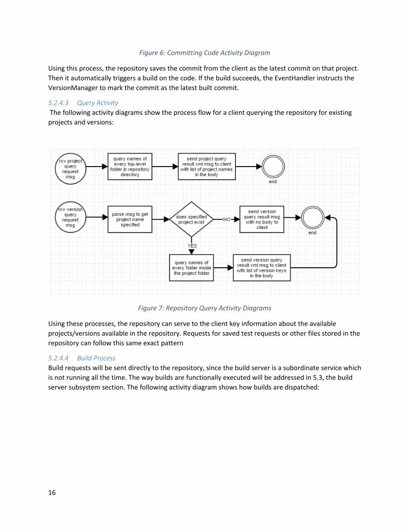
Figure 6: Committing Code Activity Diagram
Using this process, the repository saves the commit from the client as the latest commit on that project.
Then it automatically triggers a build on the code. If the build succeeds, the EventHandler instructs the
VersionManager to mark the commit as the latest built commit.
5.2.4.3 Query Activity
The following activity diagrams show the process flow for a client querying the repository for existing
projects and versions:
Figure 7: Repository Query Activity Diagrams
Using these processes, the repository can serve to the client key information about the available
projects/versions available in the repository. Requests for saved test requests or other files stored in the
repository can follow this same exact pattern
5.2.4.4 Build Process
Build requests will be sent directly to the repository, since the build server is a subordinate service which
is not running all the time. The way builds are functionally executed will be addressed in 5.3, the build
server subsystem section. The following activity diagram shows how builds are dispatched:

17
Figure 8: Repository Build Request Activity Diagram
This process flow would occur when the repository starts builds automatically in addition to receive
build requests from other services.
5.2.5 Critical Issues
5.2.5.1 Concurrent File Access
Description: In a project with many developers, it is possible that multiple developers might request to
check out the same code at the same time. This could lead to concurrent file access if two or more
threads are servicing checkout request messages.
Solution: Only a single thread should be servicing the checkout request messages. This would avoid any
concurrent file overlap if two developers attempt to check out the same version of the same project at
the same time.
5.2.5.2 Ease of Use
Description: Ease of use for the repository should be discussed in two separate contexts, how does the
design of the repository make it easy to use for employees, and for other SCF services. Each is discussed
below.
Employee ease of use: All repository interactions for users should be based in a GUI interface, of which
ease of use is a principle design goal. If the client GUI is easy to use, and actively manages all repository
interactions, this should satisfy the developer/QA/Manager ease of use concerns. For developers
managing code going in/out of the repository – everything is structured in the C# solution format,
making opening code from the repository near zero friction from the standpoint of getting started. If the
developer is familiar with visual studio, they can get started right away.
SCF Service ease of use: Other services which interact with the repository via the communication
architecture should be provided the simplest message interface possible with the repository. In the
design of each message the repository utilizes, the minimum information necessary to complete the
given operation is included in the body. See section 0 for additional detail on the repository message
interface.

18
5.2.5.3 Flexibility
Description: The repository is currently designed only for support of C# code and builds. This
architecture would require some revision.
Solutions: The future uses section in the beginning of the OCD describes a bit about how the repository
could be taken further in the future. Building upon the existing EventManager, SCFCore,
VersionManager, zip file techniques, and build dispatching model a language-agnostic repository could
be realized. A new build server architecture would be needed, and dependency management would
need to be supported independently of utilizing the solution/project tools provided by .NET.
5.3 Build Server
5.3.1 Concept Automating the build process in a continuous integration system is critical. This supports versioning
operations, automated testing, and situational awareness on the current state of the baseline. The build
server developed in this section seeks to meet this function and best serve the CI needs of a large
software company.
5.3.1.1 Modes of Operation
The build server has two modes: Developer and Deployable. Developer mode enables the developers to
run a small build server on their own machine to make sure their code is building under similar
conditions to those that will exist on the remote build server. Deployable mode will be used in the build
servers that are collocated with repositories to provide automated build services.
5.3.2 Uses and Users The build server will be used by two different user types:
1. Repository in Deployable mode. The repository will be programmatically triggering the build server
with a process start command. It doesn’t require an interface besides the build result message that will
come back to the repository when the build is complete.
2. Developer in Developer mode. Devs might run the build server at their desk to confirm that their code
builds in a very similar environment to the one it will build on via the remote repository build process.
This will require a command line interface to output status and logging from the build.
5.3.3 Structure The following simple package diagram shows the basic breakdown of packages within the Build Server:
Figure 9: Build Server Package Diagram
Package descriptions are as follows:

19
Build Server Executive: This package holds the main function, build running functions and instantiates
the SCF Core for communication/file management. Since the functionality of the build server is slim, it
doesn’t need to be divided into more packages.
SCFCore: See definition in section 5.1.
5.3.3.1 Differences between Developer and Deployable Modes
The biggest differences between developer and deployable mode (basic idea described above in
5.3.1.1), is the output direction. In developer mode, output is directed to the command line. In
deployable mode, output is directed to a logger in the SCF core, which can be used later when sending
out results messages. The developer version does not send results messages, since it’ll be displaying
them directly to the user in command line, whereas the deployable version just needs to send over
results to the repository which is collocated, so it can be addressed as localhost using the designated
repository port.
5.3.4 Activities The only activity flow conducted by the build server is building a .NET solution, and is shown in the
activity diagram below:
Figure 10: Build Activity Diagram
The above process flow occurs each time the build server is started, and when it is complete, the build
server exits entirely. The build server doesn’t need to be running all the time, since it a more on-demand
service and can be triggered by the repository which is always running.
5.3.5 Critical Issues
5.3.5.1 Build Dependencies
Description: Compiling code requires a lot of hooks to other software installed on the machine.
Compilers need to be installed and universally accessible to the build server application.
Solution: Include a configuration guide for developers using developer mode at their desk, and IT should
know how to install a compiler on a production machine for deployable mode.

20
5.3.5.2 Flexibility
Description: In the future, the SCF might be extended to additional supported languages. This might
imply a lot more functionality needs to be added within the build server to support those other
compilers and build methods.
Solution: Add a module that detects language and select compiler. Dependency info could flow in from
the repository if needed. Install each different compiler on the machine. Build code using the selected
compiler, and retain the same techniques for outputting libraries and executables. It would require
some significant additional development effort, but is not unreasonable.
5.4 Test Harness
5.4.1 Concept Testing is a critical piece in the development and lifecycle of a software system. As changes in the code
base occur, developers, quality assurance, and managers all have a vested interest in ensuring that the
baseline continues to function as these changes are integrated. In large commercial projects where
many developers contribute to a single set of interdependent packages, it quickly becomes necessary to
automate the process of testing new contributions. This section lays out a test harness application which
would serve to bootstrap test requests, execute them safely, and report the results back to the
development team, operating on clients remotely.
5.4.2 Uses and Users The test harness will be used by two groups:
1. Developers: Devs will queue up tests as needed to verify the functionality of whatever component
they are currently working on.
2. Quality Assurance: QA will queue up tests mainly aimed at integration and full baseline validation.
This requires higher performance which implies threading and scaling possibilities.
5.4.3 Structure The Test Harness module does a huge percentage of the important work in automating tests. It takes
the actual code being tested and creates a .Net application domain in which to run the test. In addition,
it handles test failures, retrieves test logs, and manages the infrastructure for running tests concurrently
in their own threads. The following package diagram shows the package breakdown to implement these
features.
21
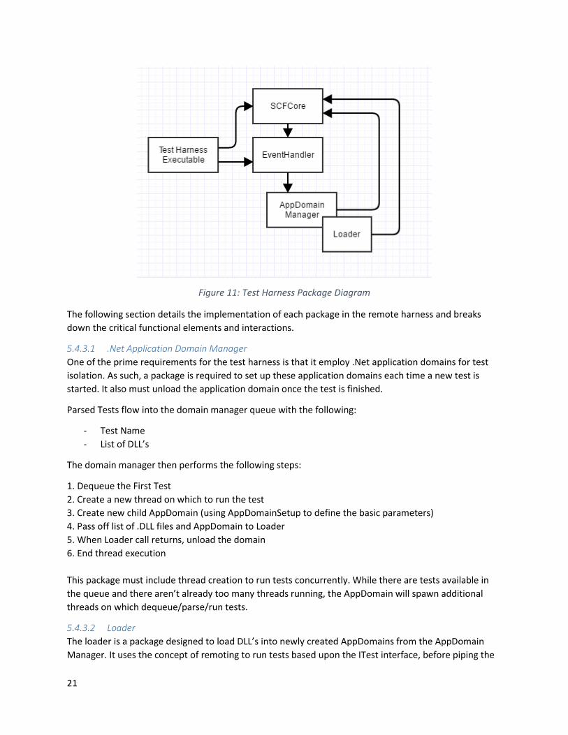
Figure 11: Test Harness Package Diagram
The following section details the implementation of each package in the remote harness and breaks
down the critical functional elements and interactions.
5.4.3.1 .Net Application Domain Manager
One of the prime requirements for the test harness is that it employ .Net application domains for test
isolation. As such, a package is required to set up these application domains each time a new test is
started. It also must unload the application domain once the test is finished.
Parsed Tests flow into the domain manager queue with the following:
- Test Name
- List of DLL’s
The domain manager then performs the following steps:
1. Dequeue the First Test
2. Create a new thread on which to run the test
3. Create new child AppDomain (using AppDomainSetup to define the basic parameters)
4. Pass off list of .DLL files and AppDomain to Loader
5. When Loader call returns, unload the domain
6. End thread execution
This package must include thread creation to run tests concurrently. While there are tests available in
the queue and there aren’t already too many threads running, the AppDomain will spawn additional
threads on which dequeue/parse/run tests.
5.4.3.2 Loader
The loader is a package designed to load DLL’s into newly created AppDomains from the AppDomain
Manager. It uses the concept of remoting to run tests based upon the ITest interface, before piping the

22
output of those tests into the logger, and returning to the AppDomain manager for unloading. The
loader must perform the following actions on an incoming AppDomain for testing.
- Take a list of DLL files and individually load them into the AppDomain
- Use remoting to call the test function on a specified DLL defined in the test request. Test
function signature defined in the ITest interface that each package being tested is required to
implement
- Send a test success Boolean to the logger
- Send any test output to the logger by using the getLog() function on the ITest interface
- Catch any exceptions that occur during the test and send them to the logs
- When execution is finished, return from bootstrapped function that was called by AppDomain
manager so that it knows when to unload current AppDomain
Essentially, the loader package is doing the heavy lifting inside the child AppDomain of running each test
that is sent in from the developers/QA.
5.4.3.3 EventHandler
This package is designed to take parsed messages from the SCFCore and task the AppDomainManager
and Loader to appropriately to run tests and report results. Essentially this package is comprised of a
large case statement which directs message and contents into the appropriate methods downstream.
5.4.4 Activities The following activity diagram shows the chain of events triggered by the client sending a test request to
the harness.
Test Request Activity Diagram
Client Test Harness Repository
Client SendQ Harness RcvQ
Send Test Request
enQWCFmsg
Parse List of DLLs Harness SendQ
enQ req's forall DLLs
deQ
enQ
Harness RcvQ
Does RepoContain DLL
enQ msg re: missing DLL
Repo RcvQWCFmsg
No
TerminateTest, send
repo msg to client
deQClient SendQClient RcvQWCFmsg
enQ
Post Failure Msg to GUI
deQ
Create FileStream
Repo SendQ enQWCFmsg
Repo File SendQ
enQHarness
File RcvQWCFfile
deQ
Write File toAppDomain bin folder
deQ
Are all DLLs present
No
Inject Loader and begin test
Yes
TestCompletes
Provide Log FileStream
Harness File SendQ
enQRepo
File RcvQWCFfile
WriteOut File
deQ
Create Log Ready
Notification
Repo SendQ enQClient RcvQ WCFmsg
Post Success & Log Ready to GUI
deQ
Figure 12: Test Request Activity Diagram

23
Note that this process requires significant interplay with both file passing and message passing between
the repository, client, and harness. This diagram serves as a direct implementation guide for the test
request handling logic.
5.4.5 Critical Issues
5.4.5.1 Critical Path: Tests
Description: The critical path for this application must be the tests themselves. Instances of tests waiting
on the harness for any significant delay must be eliminated.
Design Impacts: Code should be optimized to queue and start tests efficiently. Parallelism should be
embraced anywhere it becomes feasible, especially in later stages of the project. This will be discussed
more below.
Solutions: Harness performance can be examined through some simple observations in the AppDomain
manager. A quick timer on execution inside vs. outside the child AppDomains would provide some
valuable input on whether there are significant delays outside of tests in comparison to test execution
time. This would help guide some performance improvement work where it is needed if delays are
experienced as well.
5.4.5.2 Threading
Description: Threading will be implemented to increase parallelism and performance for each
AppDomain. Threads will be initiated in the AppDomain manager at domain creation time.
Design Impacts: Thread safety will become a concern later when threads are added. Any objects
accessed by multiple threads become vulnerable to thread safety violations.
Solutions: Thread safe implementations will be essential, especially in key data structures like the Test
Request queues, and AppDomain callback functions. Blocking queues, for example, will prevent multiple
access issues with the queue. Using a very simple threading model is key to being successful when
implementing concurrent tests. In the AppDomain Manager, threads will handle everything after the
initial dequeue of the Test Request. This ensures that complicated interactions between threads are
minimized and all initialization of tests occurs in parallel, as opposed to blocking the entire harness while
initializing a single test’s thread.
5.4.5.3 Scaling
Description: Initial development on the test harness must account for the fact that the size of tests,
number of users, deployment scenarios etc. might expand rapidly once in use.
Design Impacts: Ensure no hardcoded limits exist on size/use functionalities. Leave room for threading
to enable parallel deployment later when performance is needed to scale the number/size of tests
running.
Solutions: Assess dependencies that might prevent smooth scaling of the system. Prepare for massively
parallel deployment by allowing for threading AppDomains. Perform stress tests on the system to gauge
preparedness for scaling.
5.4.5.4 Time Costs
Description: One concern in development of the harness is the time commitment required to complete
the actual package implementations. It will admittedly probably take a large chunk of time.

24
Design Impacts: None, design shouldn’t be compromised in functionality/robustness due to tough time
constraints in this case.
Solutions: Plan well ahead of the deadline, start package development immediately, work incrementally,
test early and often.
5.4.5.5 Incorrectly Formatted Test Requests
Description: One major difficulty that the test harness might experience is incorrectly formatted test
requests. If developers get something wrong in the generation of these .xml files, the parser would fail
to be able to enqueuer that request.
Design Impacts: The user needs to be notified immediately when parsing fails. Specifically, the
messaging package should have a way to communicate to the user immediately that the file is
formatted incorrectly, allowing them to fix the error and retry gracefully.
Solutions: The messaging package in SCFCore shall have a graceful escape sequence from XML parsing
sequences, which carries with it a tag or information set on what part of the parsing failed. This will then
be displayed to the user in the console, allowing them to troubleshoot the issue and try again without
restarting the test harness application again.
5.5 Client
5.5.1 Concept The client service is the main interface between the users and SCF services. It will feature a GUI which
eliminates as much friction as possible between users and their work actions, as described in the
federation overview. Behind the GUI sits an event handler which directs actions based upon the GUI
inputs, and keeps the GUI displays up to date using dispatcher invoke mechanics. The design in this
section will seek to meet this concept.
5.5.2 Uses and Users The client is the main interface for all human users to the repository. The considerations discussed with
these user types in the federation overview users/uses section apply most directly in the Client service.
5.5.3 Structure The general structure of the client is shown in the package diagram below:
25
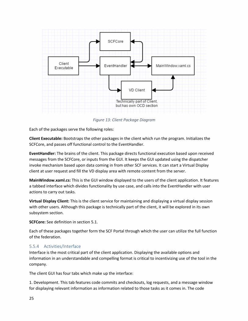
Figure 13: Client Package Diagram
Each of the packages serve the following roles:
Client Executable: Bootstraps the other packages in the client which run the program. Initializes the
SCFCore, and passes off functional control to the EventHandler.
EventHandler: The brains of the client. This package directs functional execution based upon received
messages from the SCFCore, or inputs from the GUI. It keeps the GUI updated using the dispatcher
invoke mechanism based upon data coming in from other SCF services. It can start a Virtual Display
client at user request and fill the VD display area with remote content from the server.
MainWindow.xaml.cs: This is the GUI window displayed to the users of the client application. It features
a tabbed interface which divides functionality by use case, and calls into the EventHandler with user
actions to carry out tasks.
Virtual Display Client: This is the client service for maintaining and displaying a virtual display session
with other users. Although this package is technically part of the client, it will be explored in its own
subsystem section.
SCFCore: See definition in section 5.1.
Each of these packages together form the SCF Portal through which the user can utilize the full function
of the federation.
5.5.4 Activities/Interface Interface is the most critical part of the client application. Displaying the available options and
information in an understandable and compelling format is critical to incentivizing use of the tool in the
company.
The client GUI has four tabs which make up the interface:
1. Development. This tab features code commits and checkouts, log requests, and a message window
for displaying relevant information as information related to those tasks as it comes in. The code

26
commit/checkout functions and log reception are the critical components to developers, as they will be
the only ones committing code, and in most cases, will be the only ones reading logs for debugging
purposes. The development tab is shown below.
Figure 14: Client GUI Development Tab
2. Quality Assurance. This tab features a list of available saved test requests, and a utility to submit
them. In addition, it has a build feature which allows you to select a project and submit a build request
for that code version. It is important to note however, that a build is automatically triggered upon
commit. The QA tab also has a message window which will be the best place for QA folks to check
pass/fail status on the tests. If something goes wrong, QA can direct developers to the correct log on the
development tab for debugging. It is important to note that devs may need to use the QA tab at times to
send test requests, but won’t generally have extended use there. See the QA tab below:

27
Figure 15: Client GUI QA Tab
3. Project Management. This page is largely an informative page. It shows the most up to date baseline
report which would be updated periodically, including test pass percentages, latests commits, stable
commits, etc. Managers can quickly glance at this page to get a general idea of how things are going. See
the PM tab below:

28
Figure 16: Client GUI Project Management Tab
4. Virtual Display. This page is the GUI for a virtual display client which can run collaborative coding,
video streaming, and illustration on a common canvas. More detail will be given in the subsystem
section on virtual display. The virtual display GUI outline is shown here:
Figure 17: Client GUI Virtual Display Tab
5.5.5 Critical Issues
5.5.5.1 Ease of Use
Description: It is a tough task to provide the user everything they need in an easy and digestible way.
Solution: In this design, the UI will be a simple WPF GUI interface which presents the user with all the
information needed in an easy to digest window. This design is driven by ease of implementation, and
the application. Developers and QA users don’t necessarily need a beautifully crafted GUI. Something
simple and easy that lays out the options and allows them to work quickly and efficiently is preferable.
5.5.5.2 Full Screen Virtual Display
Description: Full screen virtual display seems like a critical feature for a user writing in, drawing in, or
chatting in virtual display. This could imply a host of resizing issues for the other parts of the client GUI
which are small form factor and convenient.
Solution: Dockable windows could be implemented, letting the user detach certain tabs of the GUI,
much like you can in Visual Studio with code windows. Then the virtual display could be made full
screen, while the user can retain a small window on the side for other tab actions.

29
5.6 Virtual Display Client
5.6.1 Concept Virtual Display is a collaboration tool that can be used by developers to work together despite
geographical separation. It features three main collaboration vectors. The first is whiteboard, a drawing
tool that shows other users in your virtual display session what you are drawing at your computer. This
helps in conceptual design discussions for sketching out ideas. The second is webcam, which just
streams the video from the webcam at your computer to each of the other viewers in the session. The
third is CollabCode, which allows two or more users to edit any test file simultaneously. This tool seeks
to allow seamless collaboration between development teams across the world. The VD client will display
the virtual display state and process user-generated inputs, but the Virtual Display Server will be doing
the backend work of bringing together the various elements at play into a seamless experience.
5.6.2 Uses and Users This tool is mainly targeted at developers collaborating on specific system development tasks. However,
both QA and Managers may use this tool, as much of its functionality can still be useful and relevant to
them.
Developers: Developers are the main users of the Virtual Display Client. They will be collaborating using
the three provided modes for code reviews, cooperative coding sessions, architecture discussions, and
more. Cooperative coding will be a critical piece for developers as it facilitates code reviews that allow
live editing of the source per decisions and revisions made in the meeting.
QA: Quality Assurance would use the Virtual Display functionality less intensively that the developers,
but it would still be good for video chat meetings, collaborating on building the larger baseline-level test
requests, and building out test strategies as a team. All three modes would come into play here.
Managers: Managers would generally use the Virtual Display functionality the least. It would still be
handy for video chats, but the other collaborative functions are less helpful. More often for documents
the manager likes to share, he/she would use the collaboration server. These are typically project
management related, and would be non-text formats like MS Word, Excel, etc. which is not compatible
with CollabCode.
5.6.3 Structure The following package diagram shows the general structure of the Virtual Display client:

30
Figure 18: Virtual Display Client Structure
The following package descriptions state the role and responsibilities of the packages within the Virtual
Display Client.
Client GUI: When the user initializes or joins a session on the VD tab, the Client GUI sends a create
session or join session message to the Virtual Display server, and initializes the Virtual Display client.
When the Client GUI receives inputs inside the virtual display area, or on the controls shown in the client
GUI prototype on the right side, it forwards those inputs on to the VD Client, which passes it down to
the event handler.
Virtual Display Client: This is the main package in the virtual display client which initializes the sub
packages and passes messages from the Client GUI to the Event Handler.
EventHandler: This is the main decision engine in the VD Client. Inputs from the VD Comm, Display
Element, SCFCore, and the VD Client main package converge where the process can update views, send
file states, camera views, etc. to carry out the session.
VDComm: This is a communications module which directly uses sockets to send small high frequency
packets containing information about text inputs in CollabCode mode, video frames in webcam
streaming mode, and pencil input for whiteboard mode.
Display Element: This is a WPF compatible element which will be placed in the “Visual Display Area” in
the GUI prototype. It handles the layout engine, deciding where to efficiently place views to maximize
screen use. Frames in this view are rendered based upon VDComm inputs from the Virtual Display
Server, which maintains window state and passes content to fill each VD window in the display area.
SCFCore: See definition in section 5.1.

31
5.6.4 Activities
5.6.4.1 Webcam Stream
When a user initiates a webcam stream, the Visual Display connects to the user’s webcam and
microphone using a .NET tool called Microsoft Expression Encoder 4. This is a media based package
associated with Silverlight that provides a very nice API for capturing and encoding audio/video in an
effective and easy way. This method of capturing video was validated in a code prototype called
“VideoPrototype”. Included with the prototype is a sample 5 seconds of captured video from a webcam
using C#. This video could easily be directed into a network stream as opposed to a file capture with
some simple configuration adjustments. The following is a screenshot from the video that was
programmatically captured:
Figure 19: Video Prototype Screenshot
5.6.4.2 Whiteboard Session
If a user initiates a whiteboard session, the same video streaming technique applied to the webcam
prototype above can be applied to the screen output of the user initiating the whiteboard. Since this
mode is basically just a screen share, it would allow the use of any drawing application like OneNote,
which would not only provide an easy way to save files, but would best integrate with tablet and
touchscreen technologies on the market today for drawing without having to implement some sort of
touchscreen controller and self-contained drawing application.

32
5.6.4.3 CollabCode Session
When a CollabCode session is initiated, the user is prompted to select the path to a file to open for the
session on their local machine. This will ultimately be the file to have any collaborative changes reflected
in after the session. The file is sent to the Virtual Display Server, where it will be managed for the
duration of the session. While in collaborative session, also visibility/echoing or characters while editing
will be managed by the Virtual Display Server, since simultaneous edit will be possible, which requires
some sophisticated control. This model will be explained in the VD server section. Upon completion of a
session, the file is transferred back to the original user, where it can be committed to the repository
upon that request.
5.6.5 Critical Issues
5.6.5.1 Stream Latency
Description: The webcam and whiteboard sessions require low latency for effective viewing and
conversation. A good rule of thumb is to keep latency below 400ms for an effective voice conversation.
If this parameter is not met, collaboration sessions could be choppy and make the employees less
inclined to use the system regularly.
Solution: A small message, high speed UDP streaming connection directly created by C# on the sockets
for maximum performance is the best approach to minizine latency and provide the users with a low
latency collaboration solution.
5.7 Virtual Display Server
5.7.1 Concept The Virtual Display Server is the central point for managing virtual display sessions. It forwards UDP
traffic for streaming video and whiteboards between groups of users. It manages CollabCode sessions to
keep concurrent changes uniform in the views of documents on both user screens.
5.7.2 Uses and Users Besides employees using the Virtual Display Server indirectly via the Client GUI, the main user of the
virtual display server are the virtual display clients. The UDP interactions which define the relationship
between these services must be very fast, and barebones to make sure that collaboration remains a low
latency seamless interaction.
5.7.3 Structure The following shows the general breakdown of packages in the VD Server:

33
Figure 20: Virtual Display Server Package Diagram
Package Descriptions:
Virtual Display Server Executive:
EventHandler: This is the main decision engine in the VD Server. Inputs from the VD Comm, SCFCore,
and the CollabCode converge where the process can update views, send file states, camera views, etc.
to carry out the session.
SCFCore: See definition in section 5.1.
OTranformer: Control library implementing operational transformation operations in support of
collaborative editing.
CollabCode: This package manages a file state for the CollabCode feature using a relational database like
MongoDB. Permutations and inputs on the file come in via VD Comm from various clients who are
simultaneously editing the file. CollabCode forwards these controls into the control model of
OTransformer, which can affect the resultant file state in the database.
VDComm: This is a communications module which directly uses sockets to send small high frequency
packets containing information about text inputs in CollabCode mode, video frames in webcam
streaming mode, and pencil input for whiteboard mode.
5.7.4 Activities
5.7.4.1 File Permuatation
When a CollabCode Session is active, the VD server will continuously provide current file state for
display in clients of all users. As edits are made, it uses a technique called operational transformation,
the driving technology behind services like google docs, to maintain a consistent singular state. This
enables live code reviews where edits are made along the way by multiple developers in an extremely
efficient manner.

34
5.7.4.2 Stream Forwarding
When whiteboard or webcam streams are active, the VD comm package is efficiently forwarding the
relevant UDP streams to all users it has signed in on a given session.
5.7.5 Critical Issues
5.7.5.1 File Editing Latency
Description: While maintaining several streams of low latency data already, the VD server needs to also
be continuously streaming file updates to users of CollabCode. A reasonably low latency must be kept to
make sure that the continuous editing model provided by operational transformation remains solvent.
Solution: Quality of service rules could be added to the VD server which would automatically adjust the
frequency of file updates as latency is available to provide the best file editing latency possible without
compromising any existing stream latencies.
5.8 Communication Architecture
5.8.1 Concept When building a remote server/client apparatus, the communications piece is paramount in successful
implementation. In .NET, the Windows Communication Foundation (WCF) provides an excellent
framework within which to build SCF architecture. This critical functionality is implemented inside the
WCF Core and provided to every service in the architecture.
5.8.2 Structure
5.8.2.1 Channels
Two types of messages are designed and implemented within the SCF Core.
Message Service: This service passes non-file messages between modules. This includes XML Test
Requests, notifications of various events in the test cycle, requests for files, and small collections of
critical data (e.g. a list of log files).
File Service: This service passes files in between modules. It utilizes the ability of WCF to alias a
FileStream across a networked connection (masking away the chunked transfer), enabling a quick and
easy way to push around DLL and text files. This is ideal for larger data sets which would not be optimal
in the message service.
By leveraging each of the service types, all the necessary inter-process functionality needed to carry out
the full test cycle is available.
Since a unified WCF service infrastructure will be provided across the entire SCF, the packages that
send/receive these messages can be the same in each executable. One package (MessageService) will
define the WCF contract and methods for sending of small dataset non-file messages. The other package
(FileService) will define the WCF contract and methods for sending larger files streams between
modules. In every executable, for both FileService and MessageService, the package will have a send and
receive blocking queue. This solves the problem of multiple WCF interactions occurring simultaneously.
The blocking queue will deal with any concurrency issues, and the service can then enqueue/dequeue
messages at will.

35
5.8.2.2 Messages
The following chart identified all types of messages that can be passed throughout the SCF, and the
implementation details for their contents. These messages facilitate all inter-process communications
needed besides those conducted within the virtual display system.
Message Type Sender(s) Receiver(s) Body Contents
Checkout Request Client Repository project name
<optional> version
Checkout Success Repository Client name of .zip file
Checkout Failure Repository Client failure details string
Commit Client Repository zip file name project name
Project Query Request Client Repository n/a
Project Query Result Repository Client list of project names
Version Query Request Client Repository project name
Version Query Result Repository Client project name list of versions
Build Request Client Repository project name
version
Build Failure Repository Client project name
version build output
Build Success Repository Client project name
version
Stored Test Request Query Client Repository n/a
Stored Test Request Result Repository Client list of available test requests
Log Query Client Repository n/a
Log Query Result Repository Client list of available logs
Log Request Client Repository log filename
Log Request Failure Repository Client failure message
Test Request Client Test Harness xml test request

36
Test Result Test Harness Client result message
Log Ready Message Repository Client log filename
Display Message Any Client message to display
Collab File List Request Client Collab Server n/a
Collab File List Response Collab Server Client List of collaboration files available
VD New Session Request VD Client VD Server session name
session password
VD Join Session Request VD Client VD Server session name
session password
6 Conclusion In summary, the SCF concept is durable and feasible. The underlying services are well defined in this
document, which can be used as an implementation guide. Several code prototypes were provided to
proof out video streaming and dispose mechanic enforcement for the SCF concept. Each was successful
in its stated demonstration goals. The Software Collaboration Foundation can provide for the free and
seamless exchange of documents and ideas, along with versioning and integrating of code for a major
international software business, as shown in this OCD.