soft serve freezer -...
TRANSCRIPT

Model 161
Soft Serve Freezer
Operating Instructions
055155--M 10/02/01

Complete this page for quick reference when service is required:
Taylor Distributor:
Address:
Phone:
Service:
Parts:
Date of Installation:
Information found on the data label:
Model Number:
Serial Number:
Electrical Specs: Voltage Cycle
Phase
Maximum Fuse Size: A
Minimum Wire Ampacity: A
E October, 2001 TaylorAll rights reserved.
055155--M
Taylor Company750 N. Blackhawk Blvd.Rockton, IL 61072
The word Taylor and the Crown designare registered trademarks in the United Statesof America and certain other countries.
Table of Contents Model 161
Table of Contents
Section 1 To the Installer 1. . . . . . . . . . . . . . . . . . . . . . . . . . . . . . . . . . . . . . . . . . . .Air Cooled Units 1. . . . . . . . . . . . . . . . . . . . . . . . . . . . . . . . . . . . . . . . . . . . . . . . . . . . . . .Electrical Hook-Up Installation for 60 Cycle, 1 Phase,Supplied With Cord and Plug 1. . . . . . . . . . . . . . . . . . . . . . . . . . . . . . . . . . . . . . . . . . .Electrical Connections for Models Without Cord and Plug Supplied 1. . . . . . . . . .
Section 2 To the Operator 3. . . . . . . . . . . . . . . . . . . . . . . . . . . . . . . . . . . . . . . . . . .Compressor Warranty Disclaimer 3. . . . . . . . . . . . . . . . . . . . . . . . . . . . . . . . . . . . . . .
Section 3 Safety 4. . . . . . . . . . . . . . . . . . . . . . . . . . . . . . . . . . . . . . . . . . . . . . . . . . . .Section 4 Operator Parts Identification 5. . . . . . . . . . . . . . . . . . . . . . . . . . . . . . .
Model 161 5. . . . . . . . . . . . . . . . . . . . . . . . . . . . . . . . . . . . . . . . . . . . . . . . . . . . . . . . . . . .Beater Door Assembly 6. . . . . . . . . . . . . . . . . . . . . . . . . . . . . . . . . . . . . . . . . . . . . . . . .Accessories 7. . . . . . . . . . . . . . . . . . . . . . . . . . . . . . . . . . . . . . . . . . . . . . . . . . . . . . . . . .
Section 5 Important: To the Operator 8. . . . . . . . . . . . . . . . . . . . . . . . . . . . . . . . .Symbol Definitions 8. . . . . . . . . . . . . . . . . . . . . . . . . . . . . . . . . . . . . . . . . . . . . . . . . . . .Softecht Control Machines 9. . . . . . . . . . . . . . . . . . . . . . . . . . . . . . . . . . . . . . . . . . . . .Non--Softecht Control Machines 11. . . . . . . . . . . . . . . . . . . . . . . . . . . . . . . . . . . . . . .
Section 6 Operating Procedures 12. . . . . . . . . . . . . . . . . . . . . . . . . . . . . . . . . . . . .Assembly 12. . . . . . . . . . . . . . . . . . . . . . . . . . . . . . . . . . . . . . . . . . . . . . . . . . . . . . . . . . . .Sanitizing 15. . . . . . . . . . . . . . . . . . . . . . . . . . . . . . . . . . . . . . . . . . . . . . . . . . . . . . . . . . . .Priming 16. . . . . . . . . . . . . . . . . . . . . . . . . . . . . . . . . . . . . . . . . . . . . . . . . . . . . . . . . . . . . .Closing Procedure 17. . . . . . . . . . . . . . . . . . . . . . . . . . . . . . . . . . . . . . . . . . . . . . . . . . . .Draining Product From the Freezing Cylinder 18. . . . . . . . . . . . . . . . . . . . . . . . . . . . .Rinsing 18. . . . . . . . . . . . . . . . . . . . . . . . . . . . . . . . . . . . . . . . . . . . . . . . . . . . . . . . . . . . . .Cleaning 18. . . . . . . . . . . . . . . . . . . . . . . . . . . . . . . . . . . . . . . . . . . . . . . . . . . . . . . . . . . . .Disassembly 19. . . . . . . . . . . . . . . . . . . . . . . . . . . . . . . . . . . . . . . . . . . . . . . . . . . . . . . . . .Brush Cleaning 19. . . . . . . . . . . . . . . . . . . . . . . . . . . . . . . . . . . . . . . . . . . . . . . . . . . . . . .
Section 7 Important: Operator Checklist 20. . . . . . . . . . . . . . . . . . . . . . . . . . . . . .During Cleaning and Sanitizing 20. . . . . . . . . . . . . . . . . . . . . . . . . . . . . . . . . . . . . . . . .Troubleshooting Bacterial Count 20. . . . . . . . . . . . . . . . . . . . . . . . . . . . . . . . . . . . . . . .Regular Maintenance Checks 20. . . . . . . . . . . . . . . . . . . . . . . . . . . . . . . . . . . . . . . . . . .Winter Storage 21. . . . . . . . . . . . . . . . . . . . . . . . . . . . . . . . . . . . . . . . . . . . . . . . . . . . . . . .
Section 8 Troubleshooting Guide 22. . . . . . . . . . . . . . . . . . . . . . . . . . . . . . . . . . . .Section 9 Parts Replacement Schedule 25. . . . . . . . . . . . . . . . . . . . . . . . . . . . . . .Section 10 Parts List 26. . . . . . . . . . . . . . . . . . . . . . . . . . . . . . . . . . . . . . . . . . . . . . . . .
Wiring Diagrams 31. . . . . . . . . . . . . . . . . . . . . . . . . . . . . . . . . . . . . . . . . . . . . . . . . . . . . .
Note: Continuing research results in steady improvements; therefore, informationin this manual is subject to change without notice.

Model 161 Table of Contents
Notes:

1Model 161 To the Installer
040211
Section 1 To the Installer
This machine is designed for indoor use only.
DO NOT install the machine in an area wherea water jet could be used. Failure to follow thisinstruction may result in serious electrical shock.
Air Cooled Units
The Model 161 requires 6” (152 mm) on both sides,and 0” at the rear. Install the skirt provided on the rightside of the unit. Minimum air clearances must be metto assure adequate air flow for optimum performance.
Electrical Hook-Up Installation(60 Cycle, 1 Ph, Supplied With Cord and Plug)
This freezer is supplied with a 3-wire cord andgrounding type plug for connection to a single phase,60 cycle, branch circuit supply. This unit must beplugged into a properly grounded receptacle. The cordand plug provided for 208/230/60/1, is 20A; thereforethe wall outlet must also be 20A. Check the data label,located on the side panel, for electrical specifications.
Permanent wiringmay beemployed if requiredby localcodes. Instructions for conversion to permanent wiringare as follows:
1. Be sure the freezer is electrically disconnected.
2. Remove the appropriate panel and locate thesmall electrical box at the base of the freezer.
3. Remove the factory-installed cord and strainrelief bushing.
4. Route incoming permanent wiring through 7/8”(22 mm) hole in base pan.
5. Connect two power supply leads. Attach ground(earth) wire to the grounding lug inside theelectrical box.
6. Be sure the unit is properly grounded beforeapplying power.
FOLLOW YOUR LOCAL ELECTRICAL CODES!
Electrical Connections(Models Without Cord and Plug Supplied)
Each freezer requires one power supply for each datalabel. Check the data label on the freezer for fuse,circuit ampacity and electrical specifications. Refer tothe wiring diagram provided inside of the control box,for proper power connections.
In the United States, this equipment is intended to beinstalled in accordance with the National ElectricalCode (NEC), ANSI/NFPA 70--1987. The purpose ofthe NEC code is the practical safeguarding of personsand property from hazards arising from the use ofelectricity. This code contains provisions considerednecessary for safety. Compliance therewith andproper maintenance will result in an installationessentially free from hazard!
In all other areas of the world, equipment should beinstalled in accordance with the existing local codes.Please contact your local authorities.
Stationary appliances which are not equipped with apower cord and a plug or other device to disconnectthe appliance from the power source must have anall--pole disconnecting device with a contact gap of atleast 3 mm installed in the external installation.
CAUTION: THIS EQUIPMENT MUST BEPROPERLY GROUNDED! Failure to do so can resultin severe personal injury from electrical shock.
Beater rotation must be clockwise as viewed lookinginto the freezing cylinder.
Note: The following procedures should beperformed by a trained service technician.
To correct rotation on a three-phase unit, interchangeany two incoming power supply lines at freezer mainterminal block only. To correct rotation on asingle-phase unit, change the leads inside the beatermotor. (Follow diagram printed on motor.)
Electrical connections are made directly to theterminal block provided in the splice boxes which aremounted mid-level on the frame channel on the sidesof the freezer.

2 Model 161To the Operator
050818
Section 2 To the Operator
The Model 161 soft serve freezer has been carefullyengineered andmanufactured to give you dependableoperation.
This unit, when properly operated and cared for, willproduce a consistent quality product. Like allmechanical products, it will require cleaning andmaintenance. A minimum amount of care andattention is necessary if the operating proceduresoutlined in this manual are followed closely.
This Operator’s Manual should be read beforeoperating or performing any maintenance on yourequipment.
The Model 161 will NOT eventually compensate andcorrect for any errors during the set-up or fillingoperations. Thus, the initial assembly and primingprocedures are of extreme importance. It is stronglyrecommended that personnel responsible for theequipment’s operation, both assembly anddisassembly, go through these procedures together inorder to be properly trained and to make sure that nomisunderstandings exist.
In the event you should require technical assistance,please contact your local authorized TaylorDistributor.
If the crossed out wheeled bin symbol isaffixed to this product, it signifies that this product iscompliant with the EUDirective as well as other similarlegislation in effect after August 13, 2005. Therefore,it must be collected separately after its use iscompleted, and cannot be disposed as unsortedmunicipal waste.
The user is responsible for returning the product to theappropriate collection facility, as specified by your localcode.
For additional information regarding applicable locallaws, please contact the municipal facility and/or localdistributor.
Compressor Warranty Disclaimer
The refrigeration compressor(s) on this machine arewarranted for the term indicated on the warranty cardaccompanying this machine. However, due to theMontreal Protocol and the U.S. Clean Air ActAmendments of 1990, many new refrigerants arebeing tested and developed, thus seeking their wayinto the service industry. Some of these newrefrigerants are being advertised as drop-inreplacements for numerous applications. It should benoted that, in the event of ordinary service to thismachine’s refrigeration system, only the refrigerantspecified on the affixed data label should beused.The unauthorized use of alternate refrigerants will voidyour compressor warranty. It will be the owner’sresponsibility tomake this fact known to any technicianhe employs.
It should also be noted that Taylor does not warrant therefrigerant used in its equipment. For example, if therefrigerant is lost during the course of ordinary serviceto this machine, Taylor has no obligation to eithersupply or provide its replacement either at billable orunbillable terms. Taylor does have the obligation torecommend a suitable replacement if the originalrefrigerant is banned, obsoleted, or no longer availableduring the five year warranty of the compressor.
The Taylor Company will continue to monitor theindustry and test new alternates as they are beingdeveloped. Should a new alternate prove, through ourtesting, that it would be accepted as a drop-inreplacement, then the above disclaimer wouldbecome null and void. To find out the current status ofan alternate refrigerant as it relates to yourcompressor warranty, call the local Taylor Distributoror the Taylor Factory. Be prepared to provide theModel/Serial Number of the unit in question.

3Model 161 Safety
040211
Section 3 Safety
Weat Taylor Company are concernedabout the safetyof the operator when he or she comes in contact withthe freezer and its parts. Taylor has gone to extremeefforts to design and manufacture built-in safetyfeatures to protect both youand the service technician.As an example, warning labels have been attached tothe freezer to further point out safety precautions to theoperator.
IMPORTANT -- Failure to adhere to thefollowing safety precautions may result in severepersonal injury. Failure to comply with thesewarnings may damage the machine and itscomponents. Component damage will result inpart replacement expense and service repairexpense.
To Operate Safely:
DO NOT operate the freezer without readingthis operator’s manual. Failure to follow this instructionmay result in equipment damage, poor freezerperformance, health hazards, or personal injury.
S DO NOT operate the freezer unless it isproperly grounded.
S DO NOT operate the freezer with largerfuses than specified on the freezer datalabel.
S DO NOT attempt any repairs unless themain power supply to the freezer has beendisconnected.
Failure to follow these instructions may result inelectrocution. Contact your local authorized TaylorDistributor for service.
DO NOT use a water jet to clean or rinse thefreezer. Failure to follow these instructions may resultin serious electrical shock.
S DO NOT allow untrained personnel tooperate this machine.
S DO NOT put objects or fingers in doorspout.
S DO NOT operate the freezer unless allservice panels and access doors arerestrained with screws.
S DO NOT remove the freezer door or beaterassembly unless the control switches are inthe “OFF” position.
Failure to follow these instructionsmay result in severepersonal injury from hazardous moving parts.
USE EXTREME CAUTION when removingthe beater assembly. The scraper blades are verysharp and may cause injury.
This freezer must be placed on a levelsurface. Failure to complymay result in personal injuryor equipment damage.
DO NOT obstruct air intake and discharge openings:A minimum of 6” (152 mm) on both sides, and 0” in therear is required. Install the skirt provided on the rightside of the unit. Failure to follow this instruction maycause poor freezer performance and damage to themachine.
This freezer is designed to operate indoors, undernormal ambient temperatures of 70_--75_F(21_--24_C). The freezer has successfully performedin high ambient temperatures of 104_F (40_C) atreduced capacity.
NOISE LEVEL: Airborne noise emission does notexceed 78 dB(A) when measured at a distance of 1.0meter from the surface of the machine and at a heightof 1.6 meters from the floor.

4 Model 161Operator Parts Identification
Section 4 Operator Parts Identification
Model 161
ITEM DESCRIPTION PART NO.
1 PANEL-REAR *161* 0551292 PANEL-SIDE-RIGHT *161* 0551303 LEG-4” 3/8-16 STUD 0363974 CAP-RUBBER 0372685 SHIELD-SPLASH 0227656 TRAY-DRIP 16-7/8L X 5-1/8 0201577 PANEL-LOWER FRONT *161* 0555138 PAN-DRIP *161* 055206
ITEM DESCRIPTION PART NO.
9 PANEL A.-SIDE LEFT *161* X5512210 GASKET-HOPPER COVER 03704211 KNOB-MIX COVER 02542912 COVER A.-HOPPER X37963-SER13 PANEL A.-FRONT *161* X5520314 TUBE--FEED 030797
15 COLLAR--MIX PROBE 031628

5Model 161 Operator Parts Identification
Beater Door Assembly
ITEM DESCRIPTION PART NO.
1 DRAW VALVE 024763
2 O--RING 7/8 OD X .103 W 014402
3 SEAL--VALVE 030930
4 DOOR A.--3 SPOUT X30753--SER
5 PIVOT PIN A.--SHORT X38539
6 O--RING 5/16 OD X .070 W 016272
7 DRAW VALVE HANDLE 030564
8 HAND SCREW (STUD NUT) 034829
ITEM DESCRIPTION PART NO.
9 DESIGN CAP 014218
10 PIVOT PIN A.--LONG X38538
11 GUIDE BEARING 014496
12 CENTER DRAW VALVE 031164
13 O--RING 2--3/4 OD X .139 W 019998
14 FRONT BEARING 023262
15 BEATER ASSEMBLY X24689
16 O--RING--13/16 OD X .139 W 021278

6 Model 161Operator Parts Identification
Accessories
ITEM DESCRIPTION PART NO.
1 PAIL-6·QT. 0233482 BRUSH-REAR BRG 1” D X 2” LG 0130713 BRUSH-DOUBLE·ENDED 0130724 BRUSH-DRAW·VALVE·1” OD X
2” X 17”013073
ITEM DESCRIPTION PART NO.
5 BRUSH-MIX·PUMP·BODY-3”X7”WHITE
023316
6 LUBRICANT-TAYLOR·4·OZ. 0475187 KIT·A.-TUNE·UP X31167* SANITIZER KAY-5 125 PKTS 041082
*NOT SHOWN
7Model 161 Important: To the Operator
Section 5 Important: To the Operator
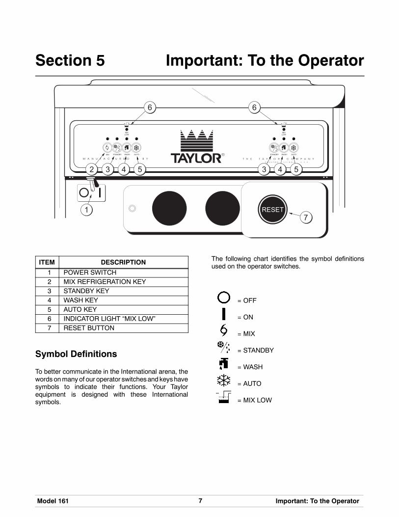
ITEM DESCRIPTION
1 POWER SWITCH2 MIX REFRIGERATION KEY3 STANDBY KEY4 WASH KEY5 AUTO KEY6 INDICATOR LIGHT “MIX LOW”7 RESET BUTTON
Symbol Definitions
To better communicate in the International arena, thewords onmany of our operator switchesand keyshavesymbols to indicate their functions. Your Taylorequipment is designed with these Internationalsymbols.
The following chart identifies the symbol definitionsused on the operator switches.
= OFF
= ON
= MIX
= STANDBY
= WASH
= AUTO
= MIX LOW

8 Model 161Important: To the Operator
Softecht Control Machines
Note: If your machine is not equipped with Softechtcontrols, please use the instructions on page 10.
Power Switch
When placed in the ON position, the power switchallows Softecht control panel operation.
MIX REF
When the MIX REF key is pressed, the light comes onindicating the mix hopper refrigeration system isoperating. MIX REF is controlled by the left side of thefreezer as viewed from theoperator end. TheMIXREFfunction cannot be cancelled unless the AUTO orSTANDBY modes are cancelled first.
STANDBY Key
The Separate Hopper Refrigeration System (SHR)and the Cylinder Temperature Retention System(CTR) are standard features on Softecht machines.The SHR incorporates the use of a separate smallrefrigeration system. This maintains the mix in thehopper below 40_(4.4_C) to assure bacteria control.The CTR works with the SHR to maintain a goodquality product. During long “No Sale” periods, it isnecessary to warm the product in the freezing cylinderto approximately 35_F to 40_F (1.7_C to 4.4_C) toprevent overbeating and product breakdown.
To activate the SHR and CTR, press the STANDBYkey. Place the end of the air tube without the hole intothe mix inlet hole.
When the STANDBY key is pressed, the light comeson, indicating the CTR (Cylinder TemperatureRetention System) has been activated. In theSTANDBY mode, the WASH and AUTO functions areautomatically cancelled. The MIX REF function isautomatically locked in to maintain the mix in thehopper.
To resume normal operation, press the AUTO key.When the unit cycles off, the product in the freezingcylinder will be at serving viscosity. At this time, placethe orifice end of the air tube into the mix inlet hole.Install the air orifice.
WASH Key
When the WASH key is pressed, the light comes on.This indicates beater motor operation. The STANDBYor AUTOmodes must be cancelled first to activate theWASH mode.
AUTO Key
When the AUTO key is pressed, the light comes on.This indicates that the main refrigeration system hasbeen activated. In the AUTO mode, the WASH orSTANDBY functions are automatically cancelled. TheMIX REF function is automatically locked in tomaintain the temperature of the mix in the mix hopper.
Note: An indicating light and an audible tone willsound whenever a mode of operation has beenpressed. To cancel any function, press the key again.The light and mode of operation will shut off.
Indicator Light - MIX LOW
Located on the front of the machine is a mix levelindicating light. When the light is flashing, it indicatesthat themix hopper has a low supply of mix and shouldbe refilled as soon as possible. Always maintain atleast 3” (76 mm) of mix in the hopper. If you neglect toadd mix, a freeze-up may occur. This will causeeventual damage to the beater, blades, drive shaft,and freezer door.
Reset Button
The reset button is located on the front of the unit. Thereset protects the beater motor from an overloadcondition. If an overload occurs, the reset mechanismwill trip. To properly reset the freezer, press the AUTOkey to cancel the cycle. Turn the power switch to theOFF position. Press the reset button firmly.
Warning: Do not use metal objects topress the reset button. Failure to comply mayresult in severe personal injury or death.
Turn the power switch to the ON position. Press theWASH key and observe the freezer’s performance.Open the side access panel. Make sure the beatermotor is turning the drive shaft in a clockwise direction(from the operator end) without binding.

9Model 161 Important: To the Operator
If the beatermotor is turning properly, press theWASHkey to cancel the cycle. Press the AUTO key on bothsides of the unit to resume normal operation. If thefreezer shuts down again, contact a servicetechnician.
Air Tube
The air tube serves two purposes. One end of the tubehas an orifice (hole) and the other end does not.
Figure 1
1. After priming the machine, place the orifice endof the air tube into the mix inlet hole. Every timethe draw handle is raised, new mix and air fromthe hopper will flow down into the freezingcylinder. This will keep the freezing cylinderproperly loaded and will maintain overrun.
2. During long “No Sale” periods, remove the airtube. Replace the air tube with the (end withouthole), into the mix inlet hole. This will preventany mix from entering the freezing cylinder.
The air tube maintains overrun and allowsenough mix to enter the freezing cylinder after adraw.

10 Model 161Important: To the Operator
Non--Softecht Control MachinesNote: If your machine is equipped with the Softechtcontrols, please use the instructions on page 7.
Push-Button Switch
If an overload condition occurs, the freezer willautomatically stop operating. To properly reset thefreezer, place the toggle switch in the OFF position.Wait two or three minutes; then press the push-buttonswitch. Place the power switch in the WASH positionand observe the freezer’s performance; place thepower switch in the AUTO position.
Note: If the freezer is unplugged from the wallreceptacle, it will be necessary to press thepush-button switch for the freezer to operate oncepower is re-established.
Power Switch
The center position is OFF. The left position is WASHwhich activates the beater motor only. The rightposition is AUTO, which activates the beater motorand the refrigeration system.
Air Tube
TheModel 161 is called upon to handle a large varietyof products (i.e., soft serve, yogurts, Italian ices,sherbets, etc.). Thus, the consistency of the mix youuse will vary. The air tube meters a combination of mixand air into the freezing cylinder. If not enough mixenters the freezing cylinder, a freeze-up may occur,which will cause eventual damage to the beater.Depending upon the product being run, you may wishto contact your local authorized Taylor Distributor tomake a slight adjustment in the air tube.
Figure 2
Note: During AUTO operation, the orifice end of thetube should be inserted in the hole in the hopper.
Taylor Quality Control
The Model 161 uses a solid state control called theWatt Control. The purpose of this solid state control isto sense the viscosity (thickness) of the product in thefreezing cylinder. With the power switch in the AUTOposition, the Watt Control will automatically keep themix in the freezing cylinder at the proper viscosity andready for serving.
Indicator Light -- Mix Low
A mix level indicating light is located at the front of themachine. When the light is on, it indicates that the mixhopper has a low supply of mix and should be refilledas soon as possible. Always maintain at least 2” (51mm) of mix in the hopper. If you neglect to add mix, afreeze-upmay occur. This will cause eventual damageto the beater assembly and to the freezer door.

11Model 161 Operating Procedures
040211
Section 6 Operating Procedures
The Model 161 is a soft serve counter model with athree spout door. Two individual flavors are availablefrom the end spouts, and an equal combination of bothis dispensed through the center spout to create a twisteffect. It has a 1.5 quart (1.4 liter) capacity freezingcylinder. The mix flows by gravity from the hopper tothe freezing cylinder through an air tube.
Duplicate the procedures where they apply for thesecond freezing cylinder.
We begin our instructions at the point where we enterthe store in the morning and find the partsdisassembled and laid out to air dry from the previousnight’s cleaning.
These opening procedures will show you how toassemble these parts into the machine, sanitize them,and prime the machine with fresh mix in preparation toserve your first portion.
Figure 3
If you are disassembling the machine for the first timeor need information to get to the starting point in ourinstructions, turn to page 18, “Disassembly”, and startthere.
Assembly
Note: When lubricating parts, use an approved foodgrade lubricant (example: Taylor Lube).
Step 1To install the beater assembly, slide the small, thicko-ring into the groove on the drive shaft of the beaterassembly. Apply an even coat of lubricant to the o-ringand the shaft. DO NOT lubricate the hex end.
Figure 4
Step 2Insert the beater assembly through the rear shellbearingat theback of the freezing cylinder andengagethe hex end firmly into the female socket. Whenproperly seated, the beater will not protrude beyondthe front of the freezing cylinder.
Figure 5
Repeat Steps 1 through 2 for the second freezingcylinder.
12 Model 161Operating Procedures
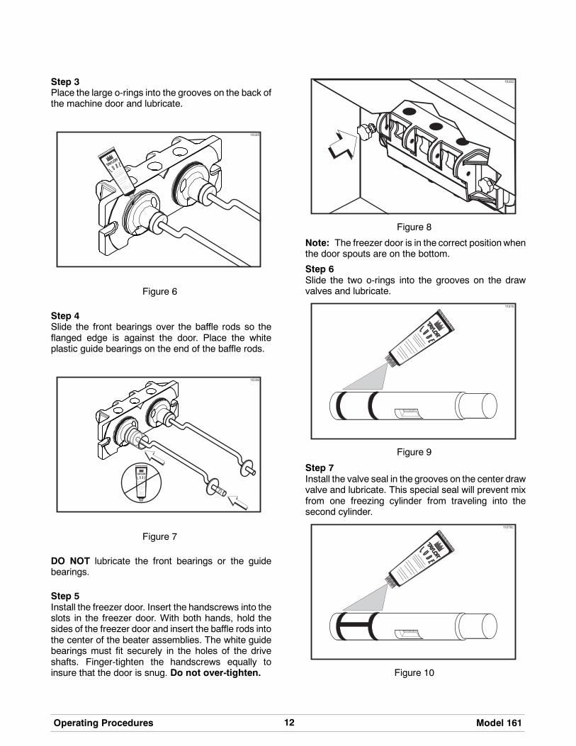
Step 3Place the large o-rings into the grooves on the back ofthe machine door and lubricate.
Figure 6
Step 4Slide the front bearings over the baffle rods so theflanged edge is against the door. Place the whiteplastic guide bearings on the end of the baffle rods.
Figure 7
DO NOT lubricate the front bearings or the guidebearings.
Step 5Install the freezer door. Insert the handscrews into theslots in the freezer door. With both hands, hold thesides of the freezer door and insert the baffle rods intothe center of the beater assemblies. The white guidebearings must fit securely in the holes of the driveshafts. Finger-tighten the handscrews equally toinsure that the door is snug. Do not over-tighten.
Figure 8
Note: The freezer door is in the correct position whenthe door spouts are on the bottom.
Step 6Slide the two o-rings into the grooves on the drawvalves and lubricate.
Figure 9
Step 7Install the valve seal in the grooves on the center drawvalve and lubricate. This special seal will prevent mixfrom one freezing cylinder from traveling into thesecond cylinder.
Figure 10

13Model 161 Operating Procedures
Step 8Lubricate the insideof the freezer door spouts from thebottom. Insert the draw valves into the freezer doorfrom thebottomuntil the slot in thedrawvalves comesinto view.
Figure 11
Step 9Slide the o-ring onto each pivot pin and lubricate.
Figure 12
Step 10Slide the tip of the draw handle into the slot of the drawvalve, starting from the right. Slide the short pivot pinthrough the far right draw handle. Slide the long pivotpin through the far left and middle draw handles.
Figure 13
Step 11Snap the design caps over the bottom of the freezerdoor spouts.
Figure 14
Step 12Lay the air tubes in the bottom of the mix hoppers.

14 Model 161Operating Procedures
Sanitizing
Step 1Prepare one gallon (3.8 liters) of an approved 100PPM sanitizing solution (example: Kay-5r). USEWARMWATER ANDFOLLOW THEMANUFACTUR-ER’S SPECIFICATIONS.
Step 2Pour the sanitizing solution into the hopper and allowit to flow into the freezing cylinder.
Figure 15
Step 3While the solution is flowing into the freezing cylinder,brush-clean the mix hopper, mix level float, mix inlethole, and air tube. Brush--clean the mix level float andstem (non--Softecht machines only).
Figure 16
Figure 17
Step 4Place the power switch in the ON position.
Figure 18
Note: Non--Softecht machines: Press thepush-button switch.
Figure 19

15Model 161 Operating Procedures
Step 5Press the WASH key. This will cause the sanitizingsolution in the freezing cylinder to be agitated. Allow itto agitate for five minutes.
Figure 20
Note: Non--Softecht machines: Place the powerswitch in the WASH position. This will cause thesanitizing solution in the freezing cylinder to beagitated. Allow it to agitate for five minutes.
Figure 21
Step 6Place an empty pail beneath the door spouts and raisethe draw valves. Momentarily pull down the centerdraw handle to sanitize the center door spout. Drawoffall of the sanitizing solution. When the sanitizer stopsflowing from the door spouts, lower the draw valvesand place the power switch in the OFF position.
Step 7With sanitized hands, stand the air tube in the cornerof the mix hopper. Place the mix level float on the mixlevel float stem (non--Softecht machines only).
Figure 22
Repeat Steps 1 through 7 for the second freezingcylinder.
Priming
Prime the machine as close as possible to the time offirst product draw.
Step 1With a pail beneath the door spouts, open the drawvalves. Fill the mix hopper with FRESH mix and allowit to flow into the freezing cylinder. This will force outany remaining sanitizing solution. When full strengthmix is flowing from the door spouts, close the drawvalves.
Note: Use only fresh mix when priming themachine.
Step 2When the mix has stopped bubbling down into thefreezing cylinder, install the air tube in the mix inlethole.
Figure 23

16 Model 161Operating Procedures
Step 3Press the AUTO key. When the unit cycles off, theproduct will be ready to serve.
Figure 24
Note: Non--Softecht machines: Place the powerswitch in the AUTO position. When the unit cycles off,the product will be ready to serve.
Figure 25
Step 4Momentarily raise the draw switch to activate therefrigeration cycle.
Step 5Place the mix hopper cover in position.
Repeat Steps 1 through 5 for the second freezingcylinder.
Step 6Install the front drip tray and splash shield under thefreezer door.
Figure 26
Step 7Slide the rear drip pan into the hole in the side panel.
Closing Procedure
To disassemble the Model 161, the following items willbe needed:
S Two cleaning pailsS Sanitized stainless steel rerun can with lidS Necessary brushes (provided with machine)S CleanerS Single service towels

17Model 161 Operating Procedures
Draining Product From theFreezing Cylinder
Step 1Press the AUTO key to cancel operation. Press theMIX REF key to cancel hopper refrigeration. Theseoperations should be cancelled as far ahead ofcleaning time as possible. This will allow frozenproduct to soften for easier cleaning.
Note: Non--Softecht machines: Place the powerswitch in the OFF position as far ahead of cleaningtime as possible. This will allow frozen product tosoften for easier cleaning.
Step 2Lift the hopper cover. Remove the air tube and mixlevel float. Take them to the sink for cleaning.
Step 3With a sanitized pail beneath the door spouts, placethe power switch in the WASH position and open thedraw valves. When all the product stops flowing fromthe door spouts, close the draw valves and place thepower switch in the OFF position. If local health codespermit, empty the rerun into a sanitized stainless steelrerun can. Cover the container and place it in thewalk-in cooler.
Repeat Steps 1 through 3 for the second freezingcylinder.
ALWAYS FOLLOW LOCAL HEALTH CODES.
Rinsing
Step 1Pour onegallon (3.8 liters) of cool, cleanwater into themix hopper. With the brushes provided, scrub the mixhopper, and the mix inlet hole.
Note: Non--Softecht machines: Scrub the mixlevel float stem.
Step 2With a pail beneath the door spouts, press the WASHkey and open the draw valves.
Note: Non--Softecht machines: Place the powerswitch in the WASH position.
Step 3Drain all the rinse water from the freezing cylinder.When the rinse water stops flowing from the doorspout, close the draw valves and press theWASH keyto cancel.
Note: Non--Softecht machines: Place the powerswitch in the OFF position to cancel.
Repeat this procedure until the rinse water beingdrawn from the freezing cylinder is clear.
Repeat Steps 1 through 3 for the second freezingcylinder.
Cleaning
Step 1Prepare one gallon (3.8 liters) of an approved cleaningsolution (example: Kay-5r). USE WARM WATERAND FOLLOW THE MANUFACTURER’S SPECIFI-CATIONS.
Step 2Pour the one gallon (3.8 liters) of cleaning solution intothe mix hopper and allow it to flow into the freezingcylinder.
Step 3While the solution is flowing into the freezing cylinder,brush-clean the mix hopper, mix level float stem andmix inlet hole.
Step 4Press the WASH key. This will cause the cleaningsolution in the freezing cylinder to agitate.
Note: Non--Softecht machines: Place the powerswitch in the WASH position.
Step 5Place an empty pail beneath the door spouts and raisethe draw valve. Draw off all the cleaning solution.When the solution stops flowing from the door spouts,close the draw valves. Press theWASH key to cancel.
Note: Non--Softecht machines: Place the powerswitch in the OFF position to cancel.
Repeat Steps 1 through 5 for the other side of themachine.

18 Model 161Operating Procedures
Disassembly
MAKE SURE THE POWER SWITCH IS INTHE “OFF” POSITION. Failure to follow thisinstruction may result in severe personal injury tofingers or hands from hazardous moving parts.
Step 1Remove the handscrews and the freezer door.Remove the beater assemblies from the freezingcylinders and take these parts to the sink for cleaning.
Step 2Remove the front drip tray and the splash shield fromthe machine. Take them to the sink for cleaning.
Brush Cleaning
Step 1Prepare a sink with an approved cleaning solution(example: Kay-5r). USE WARM WATER ANDFOLLOW THE MANUFACTURER’S SPECIFI-CATIONS.
IMPORTANT: Follow label directions, as tooSTRONG of a solution can cause parts damage, whiletoo MILD of a solution will not provide adequatecleaning.) Make sure all brushes provided with themachine are available for brush cleaning.
Step 2Remove the o-rings from the drive shafts of the beaterassemblies.
Note: To remove the o-rings, use a single servicetowel to grasp the o-ring. Apply pressure in an upwarddirection until the o-ring pops out of its groove.With theother hand, push the top of the o-ring forward, and itwill roll out of the groove and can be easily removed.If there is more than one o-ring to be removed, alwaysremove the rear o-ring first. This will allow the o-ring toslide over the forward ringswithout falling into theopengrooves.
Step 3From the freezer door, remove design caps, pivot pins,draw handles, and draw valves. Remove all o-rings.
Step 4Remove the large o-rings, front bearings, and guidebearings from the back of the freezer door.
Step 5Return to the machine with a small amount of cleaningsolution. With the black bristle brush, brush clean therear shell bearings at the back of the freezingcylinders.
Step 6Remove the rear drip pan from the side panel and takeit to the sink for cleaning.
Note: If the drip pan is filled with an excessive amountof mix, this is an indication that the drive shaft o-ring ofthe beater assembly should be replaced or properlylubricated.
Step 7Thoroughly brush clean all disassembled parts in thecleaning solution. Make sure all lubricant and mix filmis removed. Take particular care to brush clean thedraw valve cores in the freezer door. Place all thecleaned parts on a clean, dry surface to air dryovernight.
Step 8Wipe clean all exterior surfaces of the machine.
19Model 161 Important: Operator Checklist
Section 7 Important: Operator Checklist
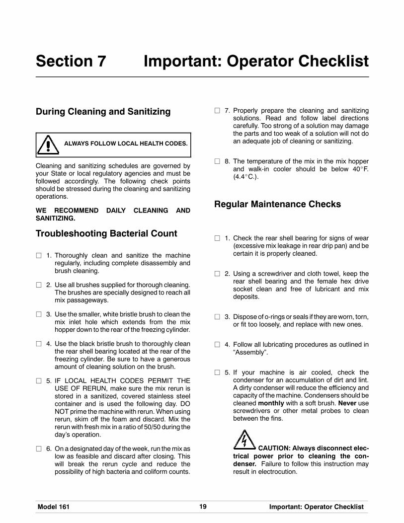
During Cleaning and Sanitizing
ALWAYS FOLLOW LOCAL HEALTH CODES.
Cleaning and sanitizing schedules are governed byyour State or local regulatory agencies and must befollowed accordingly. The following check pointsshould be stressed during the cleaning and sanitizingoperations.
WE RECOMMEND DAILY CLEANING ANDSANITIZING.
Troubleshooting Bacterial Count
j 1. Thoroughly clean and sanitize the machineregularly, including complete disassembly andbrush cleaning.
j 2. Use all brushes supplied for thorough cleaning.The brushes are specially designed to reach allmix passageways.
j 3. Use the smaller, white bristle brush to clean themix inlet hole which extends from the mixhopper down to the rear of the freezing cylinder.
j 4. Use the black bristle brush to thoroughly cleanthe rear shell bearing located at the rear of thefreezing cylinder. Be sure to have a generousamount of cleaning solution on the brush.
j 5. IF LOCAL HEALTH CODES PERMIT THEUSE OF RERUN, make sure the mix rerun isstored in a sanitized, covered stainless steelcontainer and is used the following day. DONOT prime themachinewith rerun.When usingrerun, skim off the foam and discard. Mix thererunwith freshmix in a ratio of 50/50 during theday’s operation.
j 6. On a designated day of theweek, run themix aslow as feasible and discard after closing. Thiswill break the rerun cycle and reduce thepossibility of high bacteria and coliform counts.
j 7. Properly prepare the cleaning and sanitizingsolutions. Read and follow label directionscarefully. Too strong of a solution may damagethe parts and too weak of a solution will not doan adequate job of cleaning or sanitizing.
j 8. The temperature of the mix in the mix hopperand walk-in cooler should be below 40_F.(4.4_C.).
Regular Maintenance Checks
j 1. Check the rear shell bearing for signs of wear(excessive mix leakage in rear drip pan) and becertain it is properly cleaned.
j 2. Using a screwdriver and cloth towel, keep therear shell bearing and the female hex drivesocket clean and free of lubricant and mixdeposits.
j 3. Disposeof o-rings or seals if they areworn, torn,or fit too loosely, and replace with new ones.
j 4. Follow all lubricating procedures as outlined in“Assembly”.
j 5. If your machine is air cooled, check thecondenser for an accumulation of dirt and lint.A dirty condenser will reduce the efficiency andcapacity of themachine. Condensers should becleaned monthly with a soft brush. Never usescrewdrivers or other metal probes to cleanbetween the fins.
CAUTION: Always disconnect elec-trical power prior to cleaning the con-denser. Failure to follow this instruction mayresult in electrocution.
20 Model 161Important: Operator Checklist
j 6. If your machine is equipped with an auxiliaryrefrigeration system, check the auxiliarycondenser for accumulation of dirt and lint. Adirty condenser will reduce the refrigerationcapacity of the mix hopper. Condensers mustbe cleaned monthly with a soft brush. Neveruse screwdrivers or other metal probes to cleanbetween the fins. Failure to comply may resultin electrocution.
j 7. If your machine is water cooled, check the wa-ter lines for kinks or leaks. Kinkscanoccurwhenthe machine is moved back and forth for clean-ing or maintenance purposes. Deteriorated orcracked water lines should be replaced only byan authorized Taylor mechanic.
Winter StorageIf the placeof business is to be closedduring thewintermonths, it is important to protect the freezer byfollowing certain precautions, particularly if thebuilding is subject to freezing conditions.
Disconnect the freezer from the main power source toprevent possible electrical damage.
On water cooled freezers, disconnect the watersupply. Relieve pressure on the spring in the watervalve. Use air pressure on the outlet side to blow outany water remaining in the condenser, and then add aliberal amount of permanent type auto anti-freeze.This is extremely important. Failure to follow thisproceduremay cause severe and costlydamage to therefrigeration system.
Your local Taylor distributor canperform this service foryou.
Wrap detachable parts of the freezer such as thebeater assembly and freezer door, and place them ina protected dry place. Rubber trim parts and gasketscan be protected by wrapping them withmoisture-proof paper. All parts should be thoroughlycleaned of dried mix or lubrication accumulationswhich attract mice and other vermin.

21Model 161 Troubleshooting Guide
Section 8 Troubleshooting Guide
PROBLEM PROBABLE CAUSE REMEDY PAGEREF.
1. No product beingdispensed.
a. The power switch is in theOFF position.
a. Place the power switch inthe AUTO position.
14
b. The mix level isinadequate in the mixhopper.
b. Fill the mix hopper withmix.
15
c. The beater motoroverloaded.
c. Reset the freezer. 10
d. The unit is unplugged atthe wall receptacle.
d. Plug in the power cord.Press the push-buttonswitch.
10
e. The circuit breaker istripped or the fuse isblown.
e. Place the circuit breaker inthe “ON” position, orreplace the fuse. Pressthe push-button switch.
10
f. The freezer door isincorrectly assembled.
f. See “OperatingProcedures” for properinstallation.
12
g. Product is being drawn offin excess of the freezer’scapacity.
g. Stop drawing product andallow the unit to recover.
- - -
2. The machine will notoperate in the AUTOmode.
a. The unit is unplugged. a. Plug in the power cord;press the push-buttonswitch.
10
b. The refrigeration system isnot activated.
b. Momentarily raise thedraw switch to activate therefrigeration system.
16
c. The circuit breaker istripped, or the fuse isblown.
c. Place the circuit breaker inthe ON position, orreplace the fuse. Pressthe push-button switch.
10
d. The beater motoroverloaded, causing a lossof power to the powerswitch.
d. Reset the freezer. 10
3. The product is too stiff. a. The control is set too cold. a. Contact servicetechnician.
10

22 Model 161Troubleshooting Guide
PROBLEM PROBABLE CAUSE REMEDY PAGEREF.
4. The product is too soft. a. The control is set toowarm.
a. Contact servicetechnician.
10
b. The air tube is notinstalled.
b. Install the air tube in themix inlet hole at thebottom of the mix hopper.
15
c. Out-drawing the freezer’scapacity.
c. Two 4 oz. (113.4 gram)servings in one minute.
- - -
5. The freezing cylinder wallsare scored.
a. Operating freezer withoutthe front bearing on thefreezer door.
a. Install the front bearing onthe freezer door.
12
b. The gear unit or the directdrive is out of alignment.
b. Contact servicetechnician.
- - -
6. Excessive leakage in reardrip pan.
a. A worn or defective o-ringis on the beater driveshaft.
a. Replace o-rings every 3months.
24
b. The rear shell bearing isworn.
b. Contact servicetechnician.
- - -
c. Incorrect lubricant wasused.
c. Use food grade lubricant(example: Taylor Lube).
11
d. Inadequate lubrication ofbeater drive shaft.
d. Lubricate the beater driveshaft properly.
11
7. The draw valve is leaking. a. Incorrect lubricant wasused.
a. Use food grade lubricant(example: Taylor Lube).
12
b. Worn or defective o-ringsare on the draw valve.
b. Replace o-rings every 3months.
24
c. Inadequate lubrication ofdraw valve.
c. Lubricate the draw valveproperly.
12
8. Product is not feeding intothe freezing cylinder.
a. The mix level isinadequate in the mixhopper.
a. Fill the mix hopper withmix.
15
b. The mix inlet hole isfrozen.
b. Contact servicetechnician.
10

23Model 161 Troubleshooting Guide
PROBLEM PROBABLE CAUSE REMEDY PAGEREF.
9. The unit goes out onoverload excessively.
a. There are too manyappliances plugged intothe circuit.
a. A separate 20A circuit isneeded for the freezer tooperate properly.
- - -
b. An extension cord hasbeen placed between thepower cord and the wallreceptacle.
b. If the extension cord isused, it must match thepower cord in size ofcircuit ampacity.
- - -
10. Mix from one freezingcylinder bleeds over to thesecond cylinder.
a. The center draw valveseal is worn, or isimproperly lubricated.
a. Lubricate properly andreplace seal every 3months.
12 / 24

24 Model 161Parts Replacement Schedule
Section 9 Parts Replacement Schedule
PART DESCRIPTION EVERY 3 MONTHS EVERY 6 MONTHS ANNUALLY QTY.
Beater Drive Shaft O-Ring X 2
Freezer Door O-Ring X 2
Freezer Door Front Bearing X 2
Freezer Door Guide Bearing X 2
Draw Valve O-Ring X 4
Center Draw Valve Seal X 1
Pivot Pin O-Ring X 2
Black Bristle Brush, 1” x 2” Inspect & Replaceif Necessary
Minimum 1
Double Ended Brush Inspect & Replaceif Necessary
Minimum 1
White Bristle Brush, 1” x 2” Inspect & Replaceif Necessary
Minimum 1
White Bristle Brush, 3” x 7” Inspect & Replaceif Necessary
Minimum 1

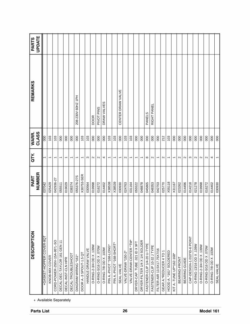
Section 10 Parts List
25
+ Available Separately
Model 161 Parts List
DESCRIPTION
PART
NUMBER
QTY.
WARR.
CLASS
REMARKS
PARTS
UPDATE
BEAR
ING
-FR
ON
T02
3262
200
0
BEAR
ING
-GU
IDE
0144
962
000
BE
AR
ING
-RE
AR
SH
ELL
*150
-52-
68*
0236
482
000
+CO
LLA
R-R
EA
RB
EA
RIN
G*1
50-2
-68*
0255
642
103
+NU
T-R
EA
RB
EA
RIN
G*1
50-5
2-68
*02
3647
200
0
+TA
B-B
EAR
ING
LOC
K*1
50-2
-68*
0250
272
000
BE
ATE
RA
.*15
0-2-
162-
168*
X24
689
210
3
+O-R
ING
-13/
16O
DX
.139
W02
1278
200
0
BE
LT-A
X24
0552
011
000
BE
LT-A
X42
0238
771
000
BLO
CK
-TE
RM
INA
L7
PO
LE02
2606
110
320
8-23
0V60
HZ
1PH
BO
AR
D-L
OG
IC-G
EN
2.6-
SD
X36
641S
ER
12
212
BO
AR
D-P
OW
ER
-GE
N1
&2
X32
326-
SE
R2
212
BR
US
H-D
OU
BLE
EN
DE
D-P
UM
P&
FEE
DT
0130
721
000
BR
US
H-D
RA
WV
ALV
E1”
OD
X2”
X17
”L01
3073
100
0
BR
US
H-M
IXP
UM
PB
OD
Y-3
”X7”
WH
ITE
0233
161
000
BRU
SH
-REA
RBR
G1I
N.D
X2IN
.LG
X14
0130
711
000
CAB
LE-R
IBBO
N-P
WR
/RE
LAY
-60
IN03
2445
210
3
CA
P-D
ES
IGN
-1.0
10”ID
-6P
OIN
T01
4218
300
0
CO
LLA
R-H
OLD
ING
0194
812
103
CO
MP
RE
SS
OR
RS
80C
1E-C
AV
-224
0519
58-2
71
512
MA
IN20
8-23
0V60
HZ
1PH
+CAP
ACIT
OR
-RU
N-2
0UF/
440V
0129
061
103
+CAP
ACIT
OR
-STA
RT-
189-
227U
F/33
0V03
3044
-11
103
+KIT
-MO
UN
TIN
G-C
OM
PR
ESSO
RR
S05
2196
100
0
+RE
LAY
-STA
RT-
CO
MP
RE
SS
OR
0519
57-2
71
103
CO
MP
RE
SS
OR
PL3
5G05
5187
-27
151
2S
HR
+CAP
ACIT
OR
-STA
RT-
43-5
2UF/
250V
0330
411
103
+RE
LAY
-STA
RT-
CO
MP
RE
SS
OR
0553
581
103
+KIT
-MO
UN
TIN
G-C
OM
PR
ESSO
R04
7704
100
0
CO
ND
EN
SE
R-A
C-1
2LX
16H
X2.
5-3
RO
W05
5140
110
3
CO
NTA
CTO
R-2
30V
AC
1PH
50/6
0HZ
0552
48-2
73
103
BE
ATE
RM
OTO
RR
ELA
Y
CO
VE
RA
.-HO
PP
ER
*162
-168
*X
3796
31
103
+ Available Separately
26Parts List Model 161
DESCRIPTION
PARTS
UPDATE
REMARKS
WARR.
CLASS
QTY.
PART
NUMBER
+GA
SK
ET-
HO
PP
ER
CO
VE
R-8
QT
0370
421
000
KNO
B-M
IXC
OVE
R02
5429
110
3
CO
RD
-PO
WE
R-2
50V
-15A
-95”
L-S
O04
2936
-27
110
3
DE
CA
L-D
EC
-TA
YLO
R16
1G
EN
1105
5511
100
0
DE
CA
L-IN
ST-
CLN
HP
R01
9029
100
0
DE
CA
L-TR
OU
BLES
HO
OT
0383
741
000
DIA
GR
AM
-WIR
ING
*161
*05
5376
-27S
100
020
8-23
0V60
HZ
1PH
DO
OR
A.-3
SPO
UT-
1.5
QT
X30
753-
SE
R1
103
HA
ND
LE-D
RA
WV
ALV
E03
0564
310
3
O-R
ING
-2-3
/4O
DX
.139
W01
9998
200
0D
OO
R
O-R
ING
-5/1
6O
DX
.070
W01
6272
200
0PI
VOT
PIN
S
O-R
ING
-7/8
OD
X.1
03W
0144
024
000
DR
AW
VA
LVE
S
PIN
A.-P
IVO
T*1
68-L
ON
G*
X38
538
110
3
PIN
A.-P
IVO
T*1
68-S
HO
RT*
X38
539
110
3
SE
AL-
VA
LVE
0309
301
000
CE
NTE
RD
RA
WV
ALV
E
VA
LVE
-DR
AW
*150
-2*
0247
632
103
VA
LVE
-DR
AW
-CE
NTE
R*T
M*
0311
641
103
DR
YER
-CAP
.TU
BE.0
21ID
X9F
T05
5522
100
0
DR
YER
-FIL
TER
1/4
X1/
4SO
LDER
0488
781
000
FAST
ENER
-CLI
P1/
4-20
U-T
YPE
0458
658
000
PA
NE
LS
FAS
TEN
ER
-CLI
P10
-32
JTY
PE
0483
532
000
RIG
HT
PA
NE
L
FILT
ER
-AIR
13.5
X17
.75X
7/16
0427
031
000
GE
AR
A.*
RE
DU
CE
R4
TO1
0257
702
212
HO
OD
A.*
161*
SO
LDE
RE
DX
5511
81
103
KIT
A.-T
UN
EU
P*1
62-1
68*
X31
167
100
0
BEAR
ING
-FR
ON
T02
3262
200
0
BEAR
ING
-GU
IDE
0144
962
000
CA
P-D
ES
IGN
-1.0
10”ID
-6P
OIN
T01
4218
300
0
O-R
ING
-13/
16O
DX
.139
W02
1278
200
0
O-R
ING
-2-3
/4O
DX
.139
W01
9998
200
0
O-R
ING
-5/1
6O
DX
.070
W01
6272
200
0
O-R
ING
-7/8
OD
X.1
03W
0144
024
000
SE
AL-
VA
LVE
0309
301
000

27
+ Available Separately
Model 161 Parts List
DESCRIPTION
PARTS
UPDATE
REMARKS
WARR.
CLASS
QTY.
PART
NUMBER
TOO
L-O
-RIN
GR
EMO
VAL-
FREE
ZER
0482
60-W
HT
100
0
LAB
EL-
CA
UTI
ON
-GR
D-P
ER
M-E
NG
/SP
0321
641
000
LAB
EL-
DO
OR
-MO
VE
PA
RT
0327
491
000
LAB
EL-
SW
-PO
WE
R-O
FF/O
N-S
YM
BO
LS05
2632
100
0
LAB
EL-
WA
RN
-CO
VE
R05
1433
500
0
LAB
EL-
WA
RN
-ELE
C-T
W-S
MA
LL03
2718
100
0
LEG
-4”3
/8-1
6S
TUD
0363
974
103
+CA
P-R
UB
BE
R03
7268
400
0
LUBR
ICAN
T-TA
YLO
R4
OZ.
0475
181
000
MA
N-O
PE
R16
105
5155
-M1
000
MO
TOR
-1/2
HP
1PH
60H
Z05
5097
-27
221
220
8-23
0V60
HZ
1PH
+CAP
ACIT
OR
-STA
RT-
60U
F-22
0/27
5V04
7703
210
3
+CAP
ACIT
OR
-RU
N-9
-11U
F/37
0V02
5962
210
3
MO
TOR
-FAN
50W
ATT
0297
70-2
71
103
+FA
N-5
BLA
DE
12”P
US
H22
DE
GC
CW
0490
091
103
NU
T-S
TUD
*150
-152
-162
-168
*03
4829
210
3H
AN
DS
CR
EW
S
OV
ER
LOA
D-T
HE
RM
AL-
2P-2
.4/3
.6A
0552
49-2
7G2
103
BE
ATE
RM
OTO
RO
VE
RLO
AD
PAIL
-6Q
T.02
3348
100
0
PA
N-D
RIP
*161
*05
5206
210
3
PA
NE
LA
.-FR
ON
T*1
61*
X55
203
110
3
PA
NE
LA
.-SID
ELE
FT*1
61*
X55
122
110
3
PA
NE
L-LO
WE
RFR
ON
T*1
61*
GE
NII
0555
131
103
PA
NE
L-R
EA
R*1
61*
0551
291
103
PA
NE
L-S
IDE
-RIG
HT
*161
*05
5130
110
3
PA
NE
L-S
KIR
T-A
IR*1
61*
0555
081
103
PLA
TE-D
EC
*161
*G
EN
II05
5512
110
3
PR
OB
EA
.-MIX
*SQ
UA
RE
*X
3092
22
103
+DIS
C-P
RO
BE
*SQ
HO
LE*
0309
652
103
+SP
AC
ER
-PR
OB
E*S
QH
OLE
*03
0966
210
3
PRO
BE
A.-T
HER
MIS
TOR
X31
602
210
3S
HR
PRO
BE
-TH
ERM
ISTO
R-B
ARR
EL-
2%TO
L03
8061
-BLK
110
3B
AR
RE
L
PU
LLE
Y-5
.7”P
ITC
HD
IAX
5/8
0414
982
103
GE
AR
PU
LLE
Y-A
K20
X5/
804
1162
210
3BE
ATER
MO
TOR

+ Available Separately
28Parts List Model 161
DESCRIPTION
PARTS
UPDATE
REMARKS
WARR.
CLASS
QTY.
PART
NUMBER
RE
SIS
TOR
A.-*
161*
CO
NT.
BO
X*
X55
449
110
3BE
ATER
MO
TOR
CO
NTA
CTO
R
SAN
ITIZ
ERKA
Y-5
125
PAC
KETS
0410
821
000
SH
ELL
A.-I
NS
ULA
TED
*161
*GE
N11
X55
629
151
2
+STU
D-N
OS
EC
ON
E-5
/16-
18X
5/16
-18
0134
962
103
SH
IELD
-SP
LAS
H*5
454-
8-75
2-33
6*02
2765
110
3
SH
RO
UD
-CO
ND
EN
SE
R*1
61*
0551
281
103
SW
ITC
HA
.-DR
AW
*161
*X
5523
42
103
+AC
TUA
TOR
-SW
ITC
H,P
LAS
TIC
0356
092
103
+AR
MA
.-SW
ITC
H*1
62-1
68*
X30
736
210
3
BEAR
ING
-SW
ITC
H02
9244
400
0
BR
AC
KE
T-S
WIT
CH
*168
*03
5524
210
3
+E-R
ING
-1/4
IN-Z
D03
4962
200
0
INS
ULA
TOR
-SW
ITC
H1/
64A
RM
ITE
0290
992
000
NU
T-P
US
HO
N-1
/2D
IA.S
HA
FT03
9735
400
0
SC
RE
W-4
-40X
1R
DH
DS
TEE
L-ZP
0288
904
000
+SC
RE
W-6
-32X
3/8
BIN
.HD
SLO
TS
S00
2201
400
0
+SP
RIN
G-C
OM
P.7
20X
.063
X2.
0002
3664
210
3
SWIT
CH
-LEV
ER-S
PDT-
15A
-125
-250
V02
7214
210
3
SWIT
CH
-PR
ESSU
RE
405
PSI-S
OLD
ER
0526
631
103
SW
ITC
H-T
OG
GLE
-4P
DT*
ON
-NO
NE
-ON
0373
941
103
TRA
Y-D
RIP
16-7
/8L
X5-
1/8
0201
571
103
TUB
E-F
EE
D-S
S-T
M-T
WIN
0307
972
103
VA
LVE
-AC
CE
SS
1/4F
LX
1/4S
OLD
ER
0444
041
103
VA
LVE
-AC
CE
SS
-1/4
MFL
X1/
4S
-90
0470
161
103
VA
LVE
-AC
CE
SS
-1/4
MFL
X3/
8OD
SD
R05
3565
210
3
VA
LVE
-EP
R1/
4S02
2665
110
3
VALV
E-E
XP-A
UTO
-1/4
SX
1/4F
PT04
7232
210
3
+BO
OT-
EX
PA
NS
ION
VA
LVE
0271
372
000
VALV
E-S
OLE
NO
ID5/
16O
RFX
1/2O
DF
0449
82-2
72
103
SUC
TIO
NLI
NE
VALV
E-S
OLE
NO
ID7/
64O
RF
X1/
4S04
3449
-27
210
3LI
QU
IDLI
NE
VA
LVE
-TR
EV
3/8X
3/8
220
*161
*05
5378
110
3LI
QU
IDR
EIN
JEC
TIO
NVA
LVE
VID
EO
-TR
AIN
FILM
-SS
-TAY
LOR
MA
TE03
7665
-V1
000

29
+ Available Separately
Model 161 Parts List
DESCRIPTION
PARTS
UPDATE
REMARKS
WARR.
CLASS
QTY.
PART
NUMBER
50H
zB
LOC
K-T
ER
MIN
AL-
7P
OLE
GR
EE
N02
4156
110
322
0-24
0V50
HZ
1PH
DIA
GR
AM
-WIR
ING
*161
*05
5376
-40S
100
0”
CO
MP
RE
SS
OR
RS
80C
1E-C
AZ-
224
0519
58-4
01
512
”
RE
LAY
-STA
RT-
CO
MP
RE
SS
OR
0519
57-4
01
103
”
CAP
ACIT
OR
-STA
RT-
64-7
7UF/
250V
0519
601
103
”
CAP
ACIT
OR
-RU
N-2
0UF/
370V
0236
061
103
”
MO
TOR
-1/2
HP
1P
H50
HZ
230V
0550
97-3
42
212
”
CAP
ACIT
OR
-STA
RT-
64-7
7UF/
250V
0266
572
103
”
VID
EO
-TR
AIN
FILM
-SS
-TAY
LOR
MA
TE03
7665
-PA
L1
000
”

Model 161055376--27SRev. 8/01

Model 161055376--40SRev. 8/01