sodimat model 9073 instruction manual - siemens-pro.ru · chapter 2 : description of the analyser...
TRANSCRIPT
SODIMAT
Model 9073
Instruction manual
03/2001 621=190=073 Rev. D


This instrument conforms to the European Directives:
- 89/336/CEE modified by the di rective 93/68/CEE- 73/23/CEE modified by the di rective 93/68/CEE
SODIMAT - Model 9073
COPYRIGHT
All rights reserved. No part of this publication may bereproduced, stored in a retrieval system, or transmitted, in anyform or by any means, electronic, mechanical, photocopying,recording or otherwise, without prior permission of Polymetron S.A.
Polymetron S. A.
Polymetron S. A. can take no res pon sabilit y forinstallation and/o r use of its equip ment if thi s is not don e inaccordance with t he appropriate issue and/o r amendment ofthe relevant manual.
The user of this manual should ensure that it i s appropriatein all details to t he exact e quip ment to b e installed and/oroperated. If in doubt, th e user s hould cont act Polymetron S .A. for advice.
WARNING
To maintain safety sta ndards, regul ar main tenance,calib ration and op eration of thi s equip ment b y qualif iedpersonn el i s essential. Read and understa ndInstructio n manual completely before operat ing orserv icing. If any fu rther detail s are requi red whi ch donot appear in this manual contact Polymetron S.A. ortheir agent.
SODIMAT - Model 9073
ii
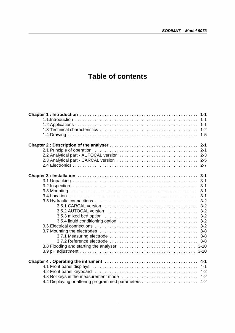
Table of contents
Chapter 1 : Introduction . . . . . . . . . . . . . . . . . . . . . . . . . . . . . . . . . . . . . . . . . . . . . . . . 1-11.1.Introduction . . . . . . . . . . . . . . . . . . . . . . . . . . . . . . . . . . . . . . . . . . . . . . . . . . 1-11.2 Applications . . . . . . . . . . . . . . . . . . . . . . . . . . . . . . . . . . . . . . . . . . . . . . . . . . 1-11.3 Technical characteristics . . . . . . . . . . . . . . . . . . . . . . . . . . . . . . . . . . . . . . . . 1-21.4 Drawing . . . . . . . . . . . . . . . . . . . . . . . . . . . . . . . . . . . . . . . . . . . . . . . . . . . . . 1-5
Chapter 2 : Description of the analyser . . . . . . . . . . . . . . . . . . . . . . . . . . . . . . . . . . . . 2-12.1 Principle of operation . . . . . . . . . . . . . . . . . . . . . . . . . . . . . . . . . . . . . . . . . . 2-12.2 Analytical part - AUTOCAL version . . . . . . . . . . . . . . . . . . . . . . . . . . . . . . . . 2-32.3 Analytical part - CARCAL version . . . . . . . . . . . . . . . . . . . . . . . . . . . . . . . . . 2-52.4 Electronics . . . . . . . . . . . . . . . . . . . . . . . . . . . . . . . . . . . . . . . . . . . . . . . . . . . 2-7
Chapter 3 : Installation . . . . . . . . . . . . . . . . . . . . . . . . . . . . . . . . . . . . . . . . . . . . . . . . . 3-13.1 Unpacking . . . . . . . . . . . . . . . . . . . . . . . . . . . . . . . . . . . . . . . . . . . . . . . . . . . 3-13.2 Inspection . . . . . . . . . . . . . . . . . . . . . . . . . . . . . . . . . . . . . . . . . . . . . . . . . . . 3-13.3 Mounting . . . . . . . . . . . . . . . . . . . . . . . . . . . . . . . . . . . . . . . . . . . . . . . . . . . . 3-13.4 Location . . . . . . . . . . . . . . . . . . . . . . . . . . . . . . . . . . . . . . . . . . . . . . . . . . . . 3-13.5 Hydraulic connections . . . . . . . . . . . . . . . . . . . . . . . . . . . . . . . . . . . . . . . . . . 3-2
3.5.1 CARCAL version . . . . . . . . . . . . . . . . . . . . . . . . . . . . . . . . . . . . . . . 3-23.5.2 AUTOCAL version . . . . . . . . . . . . . . . . . . . . . . . . . . . . . . . . . . . . . 3-23.5.3 mixed bed option . . . . . . . . . . . . . . . . . . . . . . . . . . . . . . . . . . . . . . 3-23.5.4 liquid conditioning option . . . . . . . . . . . . . . . . . . . . . . . . . . . . . . . . 3-2
3.6 Electrical connections . . . . . . . . . . . . . . . . . . . . . . . . . . . . . . . . . . . . . . . . . . 3-23.7 Mounting the electrodes . . . . . . . . . . . . . . . . . . . . . . . . . . . . . . . . . . . . . . . . 3-8
3.7.1 Measuring electrode . . . . . . . . . . . . . . . . . . . . . . . . . . . . . . . . . . . . 3-83.7.2 Reference electrode . . . . . . . . . . . . . . . . . . . . . . . . . . . . . . . . . . . . 3-8
3.8 Flooding and starting the analyser . . . . . . . . . . . . . . . . . . . . . . . . . . . . . . . 3-103.9 pH adjustment . . . . . . . . . . . . . . . . . . . . . . . . . . . . . . . . . . . . . . . . . . . . . . . 3-10
Chapter 4 : Operating the intrument . . . . . . . . . . . . . . . . . . . . . . . . . . . . . . . . . . . . . . 4-14.1 Front panel displays . . . . . . . . . . . . . . . . . . . . . . . . . . . . . . . . . . . . . . . . . . . 4-14.2 Front panel keyboard . . . . . . . . . . . . . . . . . . . . . . . . . . . . . . . . . . . . . . . . . . 4-24.3 Rollkeys in the measurement mode . . . . . . . . . . . . . . . . . . . . . . . . . . . . . . . 4-24.4 Displaying or altering programmed parameters . . . . . . . . . . . . . . . . . . . . . . . 4-2
SODIMAT - Model 9073
iix
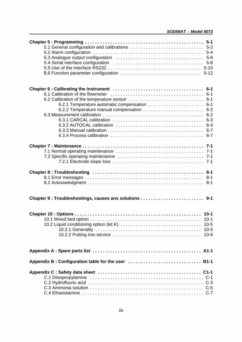
Chapter 5 : Programming . . . . . . . . . . . . . . . . . . . . . . . . . . . . . . . . . . . . . . . . . . . . . . . 5-15.1 General configuration and calibrations . . . . . . . . . . . . . . . . . . . . . . . . . . . . . 5-25.2 Alarm configuration . . . . . . . . . . . . . . . . . . . . . . . . . . . . . . . . . . . . . . . . . . . . 5-45.3 Analogue output configuration . . . . . . . . . . . . . . . . . . . . . . . . . . . . . . . . . . . 5-65.4 Serial interface configuration . . . . . . . . . . . . . . . . . . . . . . . . . . . . . . . . . . . . 5-85.5 Use of the interface RS232 . . . . . . . . . . . . . . . . . . . . . . . . . . . . . . . . . . . . . 5-1055.6 Function parameter configuration . . . . . . . . . . . . . . . . . . . . . . . . . . . . . . . . 5-12
Chapter 6 : Calibrating the instrument . . . . . . . . . . . . . . . . . . . . . . . . . . . . . . . . . . . . 6-16.1 Calibration of the flowmeter . . . . . . . . . . . . . . . . . . . . . . . . . . . . . . . . . . . . . 6-16.2 Calibration of the temperature sensor . . . . . . . . . . . . . . . . . . . . . . . . . . . . . . 6-1
6.2.1 Temperature automatic compensation . . . . . . . . . . . . . . . . . . . . . . 6-16.2.2 Temperature manual compensation . . . . . . . . . . . . . . . . . . . . . . . . 6-2
6.3 Measurement calibration . . . . . . . . . . . . . . . . . . . . . . . . . . . . . . . . . . . . . . . . 6-26.3.1 CARCAL calibration . . . . . . . . . . . . . . . . . . . . . . . . . . . . . . . . . . . . 6-36.3.2 AUTOCAL calibration . . . . . . . . . . . . . . . . . . . . . . . . . . . . . . . . . . . 6-46.3.3 Manual calibration . . . . . . . . . . . . . . . . . . . . . . . . . . . . . . . . . . . . . . 6-76.3.4 Process calibration . . . . . . . . . . . . . . . . . . . . . . . . . . . . . . . . . . . . . 6-7
Chapter 7 : Maintenance . . . . . . . . . . . . . . . . . . . . . . . . . . . . . . . . . . . . . . . . . . . . . . . . 7-17.1 Normal operating maintenance . . . . . . . . . . . . . . . . . . . . . . . . . . . . . . . . . . . 7-17.2 Specific operating maintenance . . . . . . . . . . . . . . . . . . . . . . . . . . . . . . . . . . 7-1
7.2.1 Electrode slope loss . . . . . . . . . . . . . . . . . . . . . . . . . . . . . . . . . . . . 7-1
Chapter 8 : Troubleshooting . . . . . . . . . . . . . . . . . . . . . . . . . . . . . . . . . . . . . . . . . . . . 8-18.1 Error messages . . . . . . . . . . . . . . . . . . . . . . . . . . . . . . . . . . . . . . . . . . . . . . . 8-18.2 Acknowledgment . . . . . . . . . . . . . . . . . . . . . . . . . . . . . . . . . . . . . . . . . . . . . . 8-1
Chapter 9 : Troubleshootings, causes ans solutions . . . . . . . . . . . . . . . . . . . . . . . . . 9-1
Chapter 10 : Options . . . . . . . . . . . . . . . . . . . . . . . . . . . . . . . . . . . . . . . . . . . . . . . . . . 10-110.1 Mixed bed option . . . . . . . . . . . . . . . . . . . . . . . . . . . . . . . . . . . . . . . . . . . . 10-110.2 Liquid conditioning option (kit K) . . . . . . . . . . . . . . . . . . . . . . . . . . . . . . . . 10-5
10.2.1 Generality . . . . . . . . . . . . . . . . . . . . . . . . . . . . . . . . . . . . . . . . . . 10-510.2.2 Putting into service . . . . . . . . . . . . . . . . . . . . . . . . . . . . . . . . . . . 10-6
Appendix A : Spare parts list . . . . . . . . . . . . . . . . . . . . . . . . . . . . . . . . . . . . . . . . . . . A1-1
Appendix B : Configuration table for the user . . . . . . . . . . . . . . . . . . . . . . . . . . . . . B1-1
Appendix C : Safety data sheet . . . . . . . . . . . . . . . . . . . . . . . . . . . . . . . . . . . . . . . . . C1-1C.1 Diisopropylamine . . . . . . . . . . . . . . . . . . . . . . . . . . . . . . . . . . . . . . . . . . . . . C-1C.2 Hydrofluoric acid . . . . . . . . . . . . . . . . . . . . . . . . . . . . . . . . . . . . . . . . . . . . . . C-3C.3 Ammonia solution . . . . . . . . . . . . . . . . . . . . . . . . . . . . . . . . . . . . . . . . . . . . . C-5C.4 Ethanolamine . . . . . . . . . . . . . . . . . . . . . . . . . . . . . . . . . . . . . . . . . . . . . . . . C-7

E '' E0 %%R((T
F(( lnk C Na%%
SODIMAT - Model 9073
1-1
Chapter 1 : Introduction
1.1 Introduction
The SODIMAT - Model 9073 permits themeasurement of sodium in industrialultrapure waters.
The measurement is based on a directpotentiometric technique using a highlysensitive sodium glass electrode. Thedifference of potential between the glasselectrode and the reference electrode isdirectly proportional to the sodiumconcentration as shown by the Nernst law:
1.2 Applications
Modern high-pressure power plants requirefeedwater of very high purity. Safety in thatsector is of great importance and thesodium measurement plays a specific rolecompared to pH, conductivity and silicatrace.
Actually, sodium cations and anions arealways linked. Most cations have acorrosive influence in water and vaporcooling circuits.
Because of this chemical link betweensodium ions and anions, sodiummeasurement presents particularlyimportant risks of corrosion and othereffects.
The presence of chlorides, for example,involves corrosion under power and when itexceeds allowable concentration limits.
// Main features of the SODIMAT - Model9073
3 Sample flow rate control
3 A microprocessor controlled temperaturecompensation
3 Panel or cabinet mounting possibilites
3 Two versions depending on thecalibration method chosen :
- AUTOCAL : automatic calibration byaddition of sodium known concentrationsolution
- CARCAL : calibration using calibrationcartridges of 20 and 200 ppb.

SODIMAT - Model 9073
1-2
1.3 Technical characteristics
SAMPLE
Number of channels 1
Insolubles Free of undissolved matter : turbidity < 2NTU
Temperature 5...45 C (41...113 F)B B
Pressure 0,5-6 bar (1-6 bar in CARCAL version)
Output Atmospheric pressure
Flow rate 3-6 l/h
CONNECTIONS
Mains 240 - 220 - 110 - 24 V- 15% to +10%, 50-60 Hz
Power consumption 50 VA
Terminal - Screw terminal (1 mm cable) for the input2
and output signals- Spring loaded terminal (1 mm cable) for2
mains, alarm, limits and alarm quit
Sample 4/6 mm tubing
ANALYSIS
Measuring range 0,01 ppb to 10,000 ppm programmable
Accuracy ± 5% or <±0.05 ppb whichever is greater
Reproducibility ± 3% or <±0.03 ppb whichever is greater
Response time 1 ppm to 1 ppb (90%) < 10 min100 ppb to 10 ppb (90%) < 2 min
Ambiant temperature 5...50 CB
Conditioning reagent Gaseous : diisopropylamine advised,ammoniac acceptedLiquid : éthanolamine 30 to 50%
Diisopropylamine consumption 1 l/month approx.
Calibration solution consumption 6 calibrations per bottle (if 20 minutes bycalibration point)
SODIMAT - Model 9073
1-3
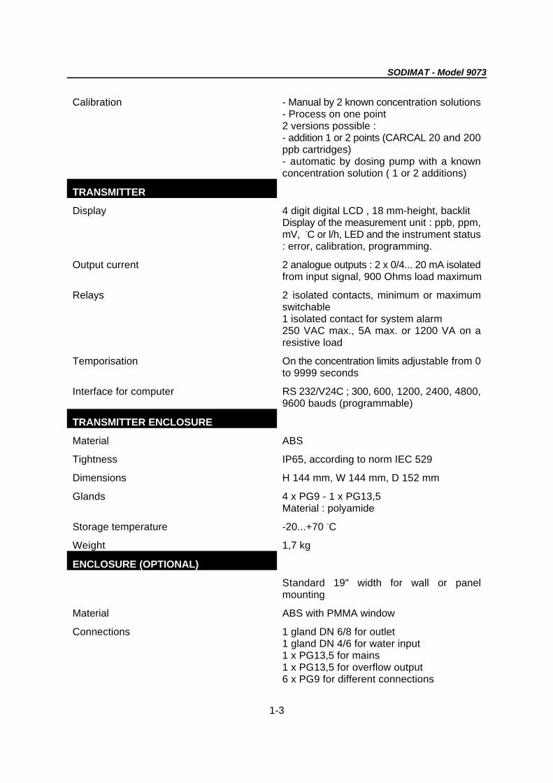
Calibration - Manual by 2 known concentration solutions- Process on one point2 versions possible :- addition 1 or 2 points (CARCAL 20 and 200ppb cartridges)- automatic by dosing pump with a knownconcentration solution ( 1 or 2 additions)
TRANSMITTER
Display 4 digit digital LCD , 18 mm-height, backlitDisplay of the measurement unit : ppb, ppm,mV, C or l/h, LED and the instrument statusB
: error, calibration, programming.
Output current 2 analogue outputs : 2 x 0/4... 20 mA isolatedfrom input signal, 900 Ohms load maximum
Relays 2 isolated contacts, minimum or maximumswitchable1 isolated contact for system alarm250 VAC max., 5A max. or 1200 VA on aresistive load
Temporisation On the concentration limits adjustable from 0to 9999 seconds
Interface for computer RS 232/V24C ; 300, 600, 1200, 2400, 4800,9600 bauds (programmable)
TRANSMITTER ENCLOSURE
Material ABS
Tightness IP65, according to norm IEC 529
Dimensions H 144 mm, W 144 mm, D 152 mm
Glands 4 x PG9 - 1 x PG13,5Material : polyamide
Storage temperature -20...+70 CB
Weight 1,7 kg
ENCLOSURE (OPTIONAL)
Standard 19" width for wall or panelmounting
Material ABS with PMMA window
Connections 1 gland DN 6/8 for outlet1 gland DN 4/6 for water input1 x PG13,5 for mains1 x PG13,5 for overflow output6 x PG9 for different connections
SODIMAT - Model 9073
1-4
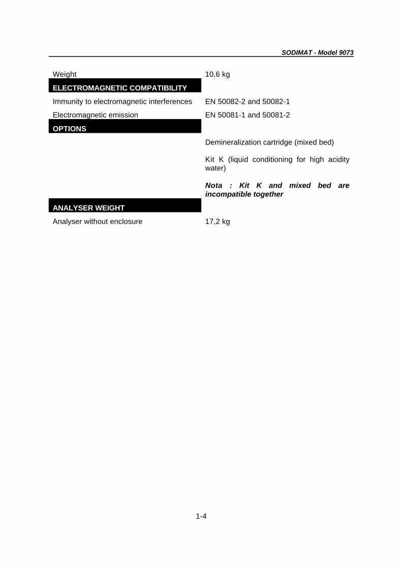
Weight 10,6 kg
ELECTROMAGNETIC COMPATIBILITY
Immunity to electromagnetic interferences EN 50082-2 and 50082-1
Electromagnetic emission EN 50081-1 and 50081-2
OPTIONS
Demineralization cartridge (mixed bed)
Kit K (liquid conditioning for high aciditywater)
Nota : Kit K and mixed bed areincompatible together
ANALYSER WEIGHT
Analyser without enclosure 17,2 kg
SODIMAT - Model 9073
1-5
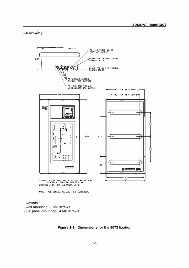
1.4 Drawing
Fixations :- wall-mounting : 6 M6 screws- 19" panel-mounting : 4 M6 screws
Figure 1-1 : Dimensions for the 9073 fixation

SODIMAT -Model 9073
2-1
Chapter 2 : Description of the analyser
2.1 Principle of operation
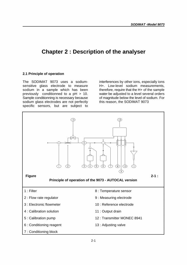
The SODIMAT 9073 uses a sodium- interferences by other ions, especially ionssensitive glass electrode to measure H+. Low-level sodium measurements,sodium in a sample which has been therefore, require that the H+ of the samplepreviously conditionned to a pH > 10. water be adjusted to a level several ordersSample conditionning is necessary because of magnitude below the level of sodium. Forsodium glass electrodes are not perfectly this reason, the SODIMAT 9073specific sensors, but are subject to
Figure 2-1 :Principle of operation of the 9073 - AUTOCAL version
1 : Filter 8 : Temperature sensor
2 : Flow rate regulator 9 : Measuring electrode
3 : Electronic flowmeter 10 : Reference electrode
4 : Calibration solution 11 : Output drain
5 : Calibration pump 12 : Transmitter MONEC 8941
6 : Conditioning reagent 13 : Adjusting valve
7 : Conditioning block
SODIMAT -Model 9073
2-2
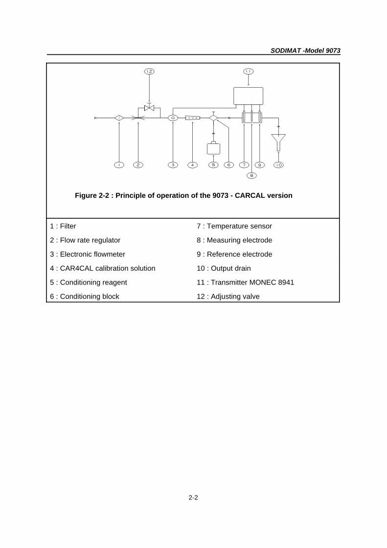
Figure 2-2 : Principle of operation of the 9073 - CARCAL version
1 : Filter 7 : Temperature sensor
2 : Flow rate regulator 8 : Measuring electrode
3 : Electronic flowmeter 9 : Reference electrode
4 : CAR4CAL calibration solution 10 : Output drain
5 : Conditioning reagent 11 : Transmitter MONEC 8941
6 : Conditioning block 12 : Adjusting valve
SODIMAT -Model 9073
2-3
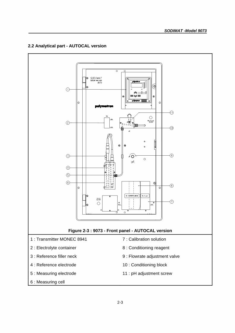
2.2 Analytical part - AUTOCAL version
Figure 2-3 : 9073 - Front panel - AUTOCAL version
1 : Transmitter MONEC 8941 7 : Calibration solution
2 : Electrolyte container 8 : Conditioning reagent
3 : Reference filler neck 9 : Flowrate adjustment valve
4 : Reference electrode 10 : Conditioning block
5 : Measuring electrode 11 : pH adjustment screw
6 : Measuring cell

SODIMAT -Model 9073
2-4
Figure 2-4 : 9073 rearview - AUTOCAL version
1 : Electronic flowmeter 9 : Inlet sample tubing
2 : Flowrate regulator 10 : Output collector
3 : Flowrate adjusting valve 11 : Temperature sensor
4 : Calibration pump 12 : Filter
5 : Conditioning reagent 13 : Measuring preamplifier
6 : Calibration solution 14 : Electrolyte container
7 : Outgoing pipe 15 : Interface box
8 : Overflow tubing
SODIMAT -Model 9073
2-5
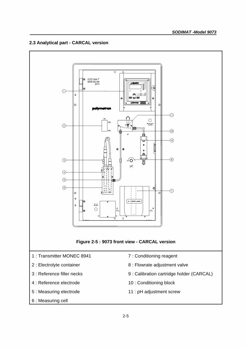
2.3 Analytical part - CARCAL version
Figure 2-5 : 9073 front view - CARCAL version
1 : Transmitter MONEC 8941 7 : Conditioning reagent
2 : Electrolyte container 8 : Flowrate adjustment valve
3 : Reference filler necks 9 : Calibration cartridge holder (CARCAL)
4 : Reference electrode 10 : Conditioning block
5 : Measuring electrode 11 : pH adjustment screw
6 : Measuring cell
SODIMAT -Model 9073
2-6
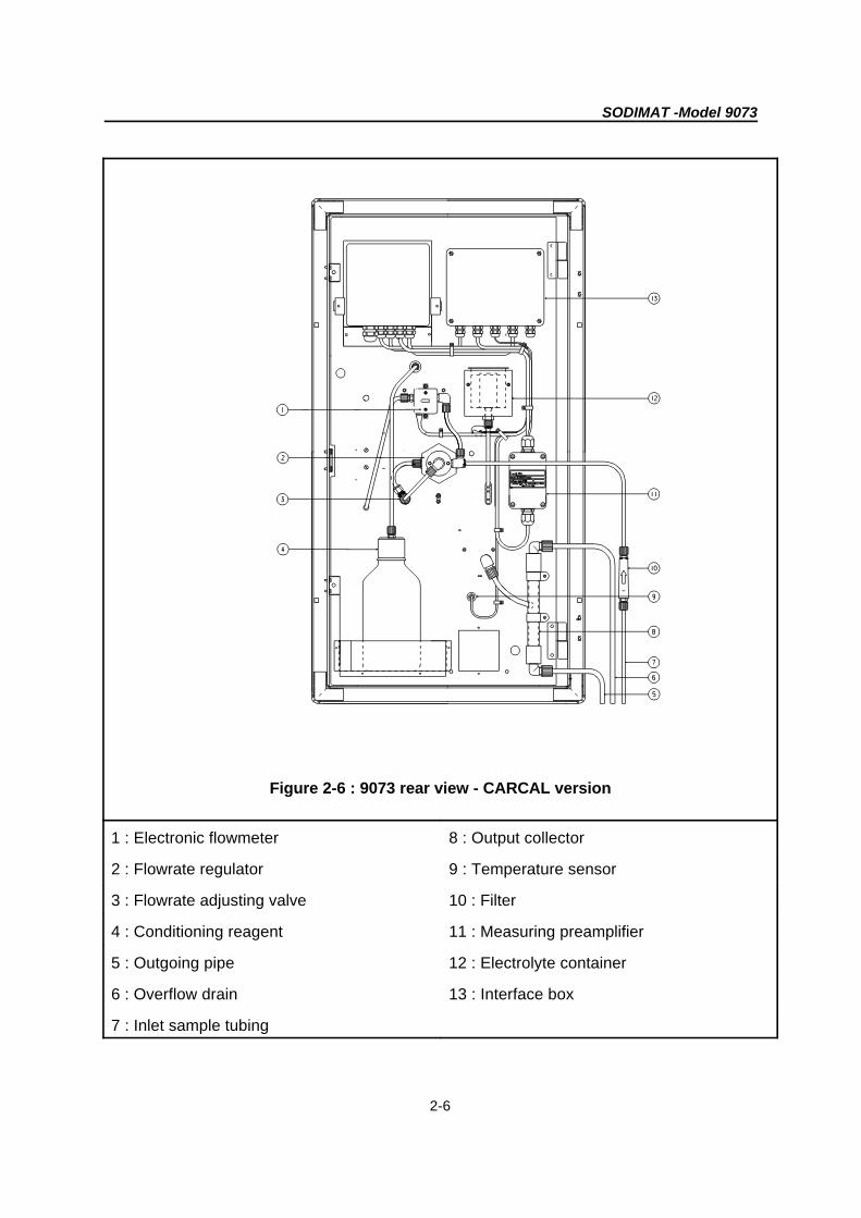
Figure 2-6 : 9073 rear view - CARCAL version
1 : Electronic flowmeter 8 : Output collector
2 : Flowrate regulator 9 : Temperature sensor
3 : Flowrate adjusting valve 10 : Filter
4 : Conditioning reagent 11 : Measuring preamplifier
5 : Outgoing pipe 12 : Electrolyte container
6 : Overflow drain 13 : Interface box
7 : Inlet sample tubing
SODIMAT -Model 9073
2-7
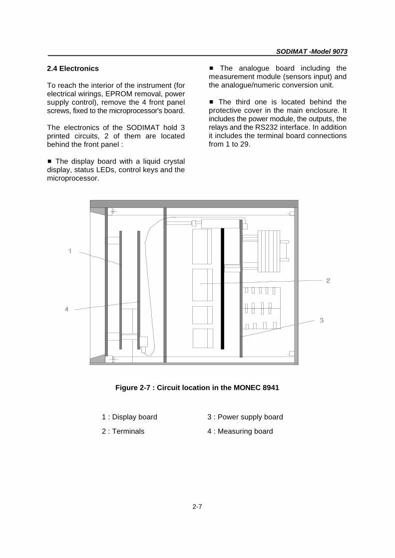
2.4 Electronics
To reach the interior of the instrument (forelectrical wirings, EPROM removal, powersupply control), remove the 4 front panelscrews, fixed to the microprocessor's board.
The electronics of the SODIMAT hold 3printed circuits, 2 of them are locatedbehind the front panel :
# The display board with a liquid crystaldisplay, status LEDs, control keys and themicroprocessor.
# The analogue board including themeasurement module (sensors input) andthe analogue/numeric conversion unit.
# The third one is located behind theprotective cover in the main enclosure. Itincludes the power module, the outputs, therelays and the RS232 interface. In additionit includes the terminal board connectionsfrom 1 to 29.
Figure 2-7 : Circuit location in the MONEC 8941
1 : Display board 3 : Power supply board
2 : Terminals 4 : Measuring board

SODIMAT - Model 9073
3-1
Chapter 3 : Installation
3.1 Unpacking
The analyser is shipped with all its sub-unitsfactory-adjusted and programmed withdefault values. Accessories and optionsworth the analyser are factory-mountedwithin the appropriate unit.
3.2 Inspection
The SODIMAT 9073 has been inspectedand tested prior to shipment. However, it isadvisable to inspect all parts immediatelyupon receipt for any damage which mayhave occured during shipment. A damagedshipping container may indicate internaldamage which may not be immediatelyobvious. If there is any evidence ofdamage, keep the shipping container.Any shortage of parts or accessories shouldbe reported to the authorized Polymetrondistributor or to :
Polymetron S.A.33, rue du Ballon
93160 Noisy-le-GrandFRANCE
3.3 Mounting
The instrument requires the followingconnections : - Sample- Drain
- Power supply
CAUTION !
Mounting should be done by qualifiedservice personnel only. Any damageon the instrument by a non qualifiedperson cancels the warranty.
3.4 Location
The analyser should be placed in anyconvenient location, e.g., installation ontothe sampling rack. The location should beeasily accessible to facilitate the checkingand the regular maintenance.
Before any electrical or hydraulicconnection, check the environmentcorresponds to the instrument configuration:
- voltage- frequency- sample supply pressure- sample temperature- ambient temperature
Choose a dry site for your instrument if it isa panel-mounting type instrument. Checkalso the quality of the conditioning reagent: diisopropylamine for the gaseousconditioning and ethanolamine or ammoniafor the liquid conditioning. These chemicalproducts should be of “per analysis” quality.

SODIMAT - Model 9073
3-2
3.5 Hydraulic connections
3.5.1 CARCAL version (see figure 2-4)
- Fill in the conditioning reagent bottle andconnect it to the circuit.
- Put a filter cartridge on the CARCALholder respecting the flow direction shownon the cartridge.
- Set the sample drain. Caution ! The outletis gravitary, it shoud be as direct aspossible (avoid tubing twist).
3.5.2 AUTOCAL version (see figure 2-2) 33 MONEC
- Fill in the conditioning reagent bottle and Never attempt to switch on the instrumentconnect it to the circuit. before all the connections have been
- Set the sample drain. Caution ! The outlet Before connecting the instrument check theis gravitary, it shoud be as direct as selected power supply corresponds to yourpossible (avoid tubing twist). power supply.- Fill in the calibration solution bottle with Remove the front panel and the protectivethe adequat and fresh solution and put the cover to reach the main selection bridges.strainer (see table in paragraph 6.2.2 for An aluminuim plate shows the terminalthe concentration used). function and its connection with the external
Caution ! The calibration solution should befree of solid body which may damage thecalibration pump.
Avoid any direct handling of parts in contact
with the calibration solution : it may causepollution.
3.5.3 Mixed bed option
Installing this option requires a qualifiedPolymetron technician. L See Chapter 9 : Options
3.5.4 Liquid conditioning option (kit K)L See Chapter 9 : Options
3.6 Electrical connections
realised.
elements from the monec.
Power supply Min. range Max. range Bridges' Fuses(V) allowed allowed location mA
- 10 % + 10 %
24 20,4 26,4 X1, X3 T1,25 A110 94 121,0 X2, X4, X6 T250 mA127 115 146,0 X1, X4, X6 T250 mA220 187 242,0 X2, X5 T125 mA240 207 268,0 X1, X5 T125 mA
Install as many cable glands as necessary. Start with the ground connection.
SODIMAT - Model 9073
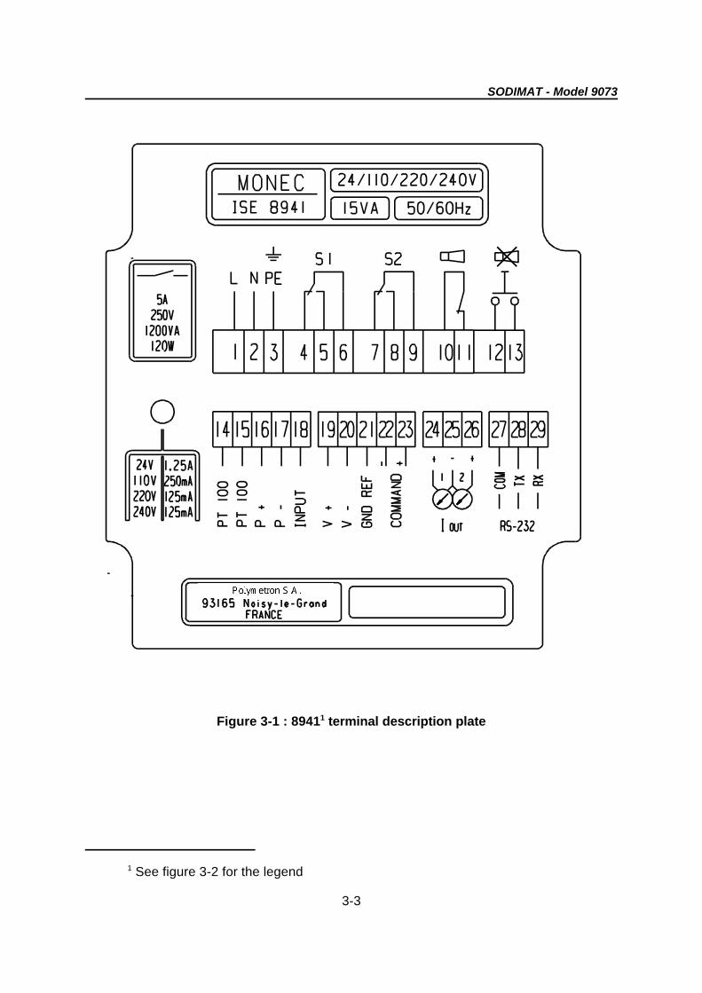
See figure 3-2 for the legend1
3-3
Figure 3-1 : 8941 terminal description plate1

SODIMAT - Model 9073
3-4
Figure 3-2 : 8941 terminals
1/2/3 : Mains (linked to B2 of interface box, see 18 : Measurefigure 3-3)
4/5/6 : Setpoint 1 19 : +12V preamplifier and flowmeter supply
7/8/9 : Setpoint 2 20 : -12V preamplifier and flowmeter supply
10/11 : System alarm 21 : Reference
12/13 : Alarm remote acquit (single pole 22/23 : Interface linkcontact) and remote automatic calibration (close contact during 3 seconds)
14/15 : Temperature sensor Pt100 24/25/26 : Analogue outputs
16/17 : Flowrate measurement 27/28/29 : RS232 link

SODIMAT - Model 9073
3-5
RS232 connection
PLUG 9 CONTACTS MONEC C
Terminal 5 GND COM (27)
Terminal 2 RXD TXD (28)
Terminal 3 TXD RXD (29)
PLUG 25 CONTACTS MONEC C
Terminal 7 GND COM (27)
Terminal 2 RXD TXD (28)
Terminal 3 TXD RXD (29)
33 Interface box
Power supply Min. range Max. range Bridges' Fuses(V) allowed allowed location mA
- 10 % + 10 %
24 20,4 26,4 X1, X3 T2A110 94,0 121,0 X2, X4, X6 T500 mA134 120,6 147,4 X1, X4, X6 T315 mA220 187,0 242,0 X2, X5 T200 mA244 207,0 268,0 X1, X5 T200 mA

1 2 3 4 5B3
B4
1 2 3 4 5 6
B1
B2
PH N T PH N T
PP EV PLEE+ +- -
23 22
SODIMAT - Model 9073
3-6
Figure 3-3 : Interface box terminals
B1 : Analyser power supply B3 5 : Shielded connecting cable forcommunication with the transmitter
B2 : Transmitter power supply B4 1/2 : Conditionning peristaltic pumpconnection (see kit K option)
B3 1/2 : Push-button for mixed bed B4 3/4 : Valve connection (see mixed bed(see mixed bed option) option)
B3 3/4 : Communication with the transmitter B4 5/6 : Dosing pump connection (AUTOCAL)

SODIMAT - Model 9073
3-7
33 PREAMPLIFIER
Figure 3-4 : Preamplifier connections

diffusion ring
electrolytecompartments
SODIMAT - Model 9073
3-8
3.7 Mounting the electrodes
3.7.1 Measuring electrode
- Take out the measuring electrode from itsbox and pull out carefully the protective cap.
- Check the electrode bulb is filled withelectrolyte. If there is any bubble, shake theelectrode straight up.
- Screw the measuring electrode in itscompartment (right side of the cell). Theelectrode tightness should ensure a slightsquashing of the washer (0.5 mmmaximum).Never force it.
- Remove the connector cap and connectthe cable (thick wire with AS9 connector) byscrewing till tightness on the washer.
Caution ! The connector should never bewet (high impedance).
3.7.2 Reference electrode ì Take out the reference electrode from itsbox and remove carefully its protection cap.
- Remove both caps from the electrolytecompartments.
- Drain and rinse the electrolytecompartments by shaking it slightly.
Figure ìì
- If the diffusion ring is clogged (electrolytecrystals), plunge and rinse the electrode ina water with low sodium content. (SeeFigure ì).
í Fill in both compartments with theelectrolyte supplied with the instrument (seereference in appendix A). This handlingshould be done with the electrode slightlyinclined for the electrolyte to currentregularly without any air blocked in theelectrode.(see Figure í).- If there is any bubbles trapped, obturateboth inlets with the caps removed in step ìand shake slightly the electrode to removethe air.
Figure íí

electrolyte
SODIMAT - Model 9073
3-9
î Put the electrode into its compartment ;Do not block the diffusion ring in the cell.(see Figure î).
- Screw the reference electrode in its place.The electrode tightness should ensure aslight squashing of the washer (0.5 mmmaximum).L Never force it !
Figure îî
ïRemove the connector cap and connectthe cable (thin wire with AS7 connector) byscrewing till tightness on the washer.
- Mount the electrolyte feeding pipes (seeFigure ïï).
Figure ïï - sample height in the measuring cell
ð Fill in half the container with electrolyte(See Figure ð).
-Open very slightly the lower feeding pipeand squeeze it to let the electrolyte currentdown to the electrode (use absorbent paperto sponge the electrolyte).
-Open very slightly the upper feeding pipeand squeeze it to let the electrolyte currentdown to the electrode (use absorbent paperto sponge the electrolyte).
Figure ðð
- If necessary add electrolyte (3/4 of thecontainer) and put its cap back..
3.8 Floading and starting the analyser
Before flooding, check the adjusting valve isclosed (clockwise) (Figure 2-1 or 2-3).
L Flooding should be done beforegrounding
Flood the instrument, adjust the flowrate to4 l/h and check the following points :
- regular sample drain (no output sealing)
(output side on the left side) sufficient toensure a regular drain.

SODIMAT - Model 9073
3-10
WARNING ! The adjustment with thescrew is sensitive. Proceed by step of1/10 of turn approx.).
If the evacuation is stopped for any reason, As an indication, the pH values according toturn off immediately the supply valve. the sodium measured are :
If the levels in the cell are unstable, checkthe electrode adjustment is correct andensures tightness.
After 15 minutes, check :
- the sample level in the cell is stable.
- the regular generation of bubbles in theconditioner (if the gaseous conditioning ischosen). If there is any problem, refer tochapter 7 : maintenance.
3.9 pH adjustment
In the case of an instrument equipped witha diisopropylamine gaseous conditioningsystem, it is possible to adjust theconditioning flowrate to avoid anyoverconsumption of reagent.
This adjustment may be realised when theinstrument is stabilised using the screw (12)located on the conditioning block.
The rotation direction is indicated on thepanel :- clockwise : decrease of conditioningreagent (pH>)- anticlockwise : increase of conditioningreagent (pH<)
Concentration pH
[Na] > 10 ppb >9
1 < [Na] < 10 ppb >10
[Na]< 1 ppb >10.5pH should be measured with electrodes(never use paper pH test).
In the case of an instrument equipped witha liquid conditioning system (Kit K), theadjusting screw should remain closed.
When the instrument is stabilized, switch onthe analyser, the following messages aredisplayed :
- "8 8 8 8" : auto test, all the LEDs arealight- "ISE" : for yhe selective ion electrode - " v X.XX" or X.XX is the software versionprogrammed in the instrument.
This sequence lasts approximately 30seconds, then the instrument goes to themeasuring mode (concentration).
After this start-up, it is required to let theinstrument run about 6 hours beforecalibrating. During this time, the instrumentshould stabilize and reach a concentrationvalue close to the sample one thanks to thestandard parameters factory-programmed.
A calibration can then be launched and theinstrument calculates its parametersaccording to your sample characteristics.
SODIMAT - Model 9073
4-1
Chapter 4 : Operating the instrument
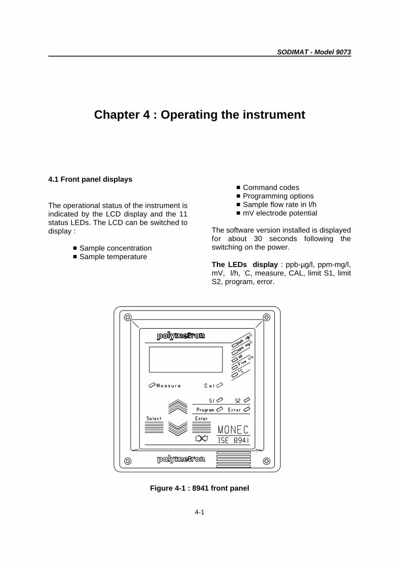
4.1 Front panel displays
The operational status of the instrument isindicated by the LCD display and the 11status LEDs. The LCD can be switched todisplay :
# Sample concentration# Sample temperature
# Command codes# Programming options# Sample flow rate in l/h# mV electrode potential
The software version installed is displayedfor about 30 seconds following theswitching on the power.
The LEDs display : ppb-µg/l, ppm-mg/l,mV, l/h, C, measure, CAL, limit S1, limitB
S2, program, error.
Figure 4-1 : 8941 front panel

SODIMAT - Model 9073
4-2
4.2 Front panel keyboard
Four keys ensure the MONEC operation :
O SELECT : enables to go from theprogramming mode to the measuring modeand vice versa.
O SCROLL/UP AND DOWN : scrollthrough the parameters being measured or,while in the programming mode, set orchange the value of various parameters.
O ENTER : invokes a command oracknowledges validity of data input.
4.3 Rollkeys in the measurement mode
Five parameters are simultaneouslydisplayed (3 are measured) The parametersare selected with the scroll up/down keys
and the following parameters can bedisplayed :
ConcentrationTemperatureElectrode potential in mVFlowrate in l/hCAL (calibration)
4.4 Displaying or altering programmedparameters
Pressing SELECT accesses theprogramming mode ; the correspondingLED PROGRAM lights up. Using SCROLLUP/DOWN keys allows the list ofcommands to be scannedd through. Whenthe desired command appears, pressENTER.
Figure 4-2 : 8941 front panel controls

SODIMAT - Model 9073
4-3
IMPORTANT
If the PROGRAMMING protection is chosen (command 910 "argument 1"), it isimpossible to modify these values.
The display indicates the argument After the programming it is possible toprogrammed, the first figure flashes. enter the sign (+ , -, point or unit) with the
Pressing ENTER allows you to go to thesecond figure. After the last ENTER, the option is stored
Pressing SELECT allows you to leave this command.command without storing the change.
Follow the same procedure to program the possible by pressing SELECT.4 figures.
scrolling keys.
and the instrument goes to the next
Returning to the measuring mode is

SODIMAT - Model 9073
5-1
Chapter 5 : Programming
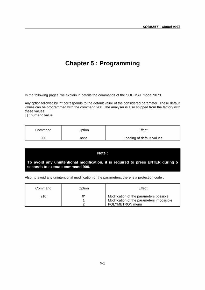
In the following pages, we explain in details the commands of the SODIMAT model 9073.
Any option followed by "*" corresponds to the default value of the considered parameter. These defaultvalues can be programmed with the command 900. The analyser is also shipped from the factory withthese values.[ ] : numeric value
Command Option Effect
900 none Loading of default values
Note :
To avoid any unintentional modification, it is required to press ENTER during 5seconds to execute command 900.
Also, to avoid any unintentional modification of the parameters, there is a protection code :
Command Option Effect
910 0* Modification of the parameters possible1 Modification of the parameters impossible2 POLYMETRON menu

SODIMAT - Model 9073
5-2
5.1 General configuration and calibrations
SODIMAT - Model 9073
5-3
Command Option Function
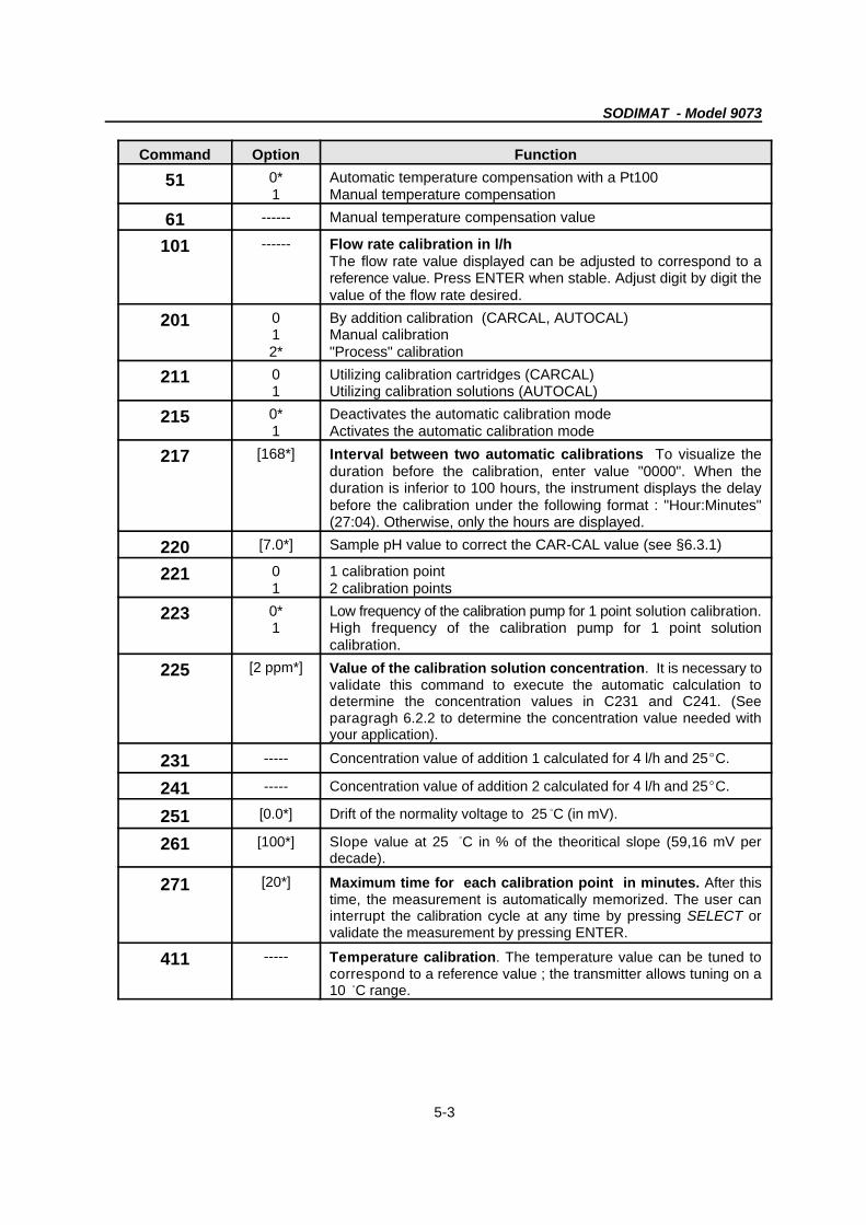
51 0* Automatic temperature compensation with a Pt1001 Manual temperature compensation
61 ------ Manual temperature compensation value
101 ------ Flow rate calibration in l/h The flow rate value displayed can be adjusted to correspond to areference value. Press ENTER when stable. Adjust digit by digit thevalue of the flow rate desired.
201 0 By addition calibration (CARCAL, AUTOCAL)1 Manual calibration2* "Process" calibration
211 0 Utilizing calibration cartridges (CARCAL)1 Utilizing calibration solutions (AUTOCAL)
215 0* Deactivates the automatic calibration mode1 Activates the automatic calibration mode
217 [168*] Interval between two automatic calibrations To visualize theduration before the calibration, enter value "0000". When theduration is inferior to 100 hours, the instrument displays the delaybefore the calibration under the following format : "Hour:Minutes"(27:04). Otherwise, only the hours are displayed.
220 [7.0*] Sample pH value to correct the CAR-CAL value (see §6.3.1)
221 0 1 calibration point1 2 calibration points
223 0* Low frequency of the calibration pump for 1 point solution calibration.1 High frequency of the calibration pump for 1 point solution
calibration.
225 [2 ppm*] Value of the calibration solution concentration. It is necessary tovalidate this command to execute the automatic calculation todetermine the concentration values in C231 and C241. (Seeparagragh 6.2.2 to determine the concentration value needed withyour application).
231 ----- Concentration value of addition 1 calculated for 4 l/h and 25EC.
241 ----- Concentration value of addition 2 calculated for 4 l/h and 25EC.
251 [0.0*] Drift of the normality voltage to 25 C (in mV). B
261 [100*] Slope value at 25 C in % of the theoritical slope (59,16 mV per B
decade).
271 [20*] Maximum time for each calibration point in minutes. After thistime, the measurement is automatically memorized. The user caninterrupt the calibration cycle at any time by pressing SELECT orvalidate the measurement by pressing ENTER.
411 ----- Temperature calibration. The temperature value can be tuned tocorrespond to a reference value ; the transmitter allows tuning on a10 C range. B
SODIMAT - Model 9073
5-4
5.2 Alarm configuration

SODIMAT - Model 9073
5-5
Two different ways to acquit manually the alarm system :
1. By pressing ENTER.2. Remotely by the single pole contact (see figure 3-2)
Command FunctionOption
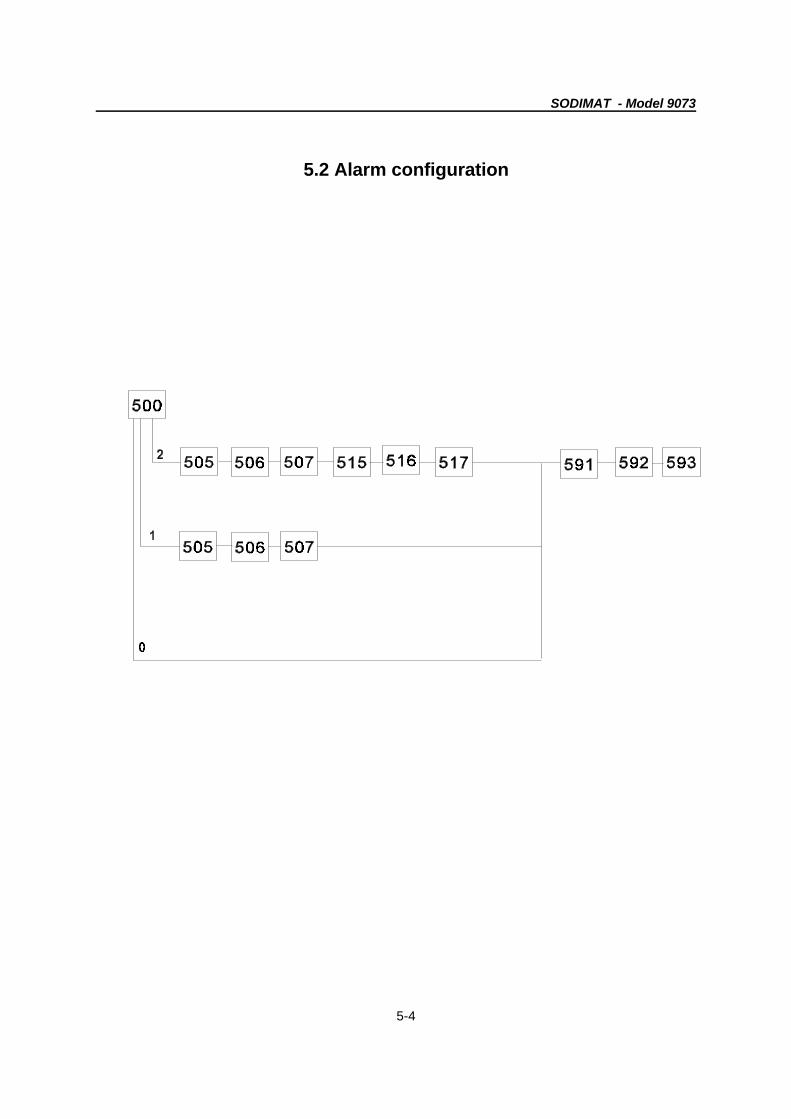
500 0 Limits S1 and S2 not active1 Limit S1 active and limit S2 not active2* Limits S1 and S2 active
505 0* S1 defined as low limit setpoint1 S1 defined as high limit setpoint
506 [0.01*] S1 value in ppb or ppm
507 [0*] Delay time between 0...9999 seconds
515 0 S2 defined as low limit setpoint1* S2 defined as high limit setpoint
516 [999.9*] S2 value in ppb or ppm
517 [0*] Delay time between 0...9999 seconds
591 0* Relay S1 normally open if no alarm condition1 Relay S1 activated if no alarm condition
592 0* Relay S2 normally open if no alarm condition1 Relay S2 activated if no alarm condition
593 0 Relay S3 off1* Relay S3 activated by an alarm system with manual reset2 Relay S3 activated by an alarm system with automatic reset
SODIMAT - Model 9073
5-6
5.3 Analogue output configuration
SODIMAT - Model 9073
5-7
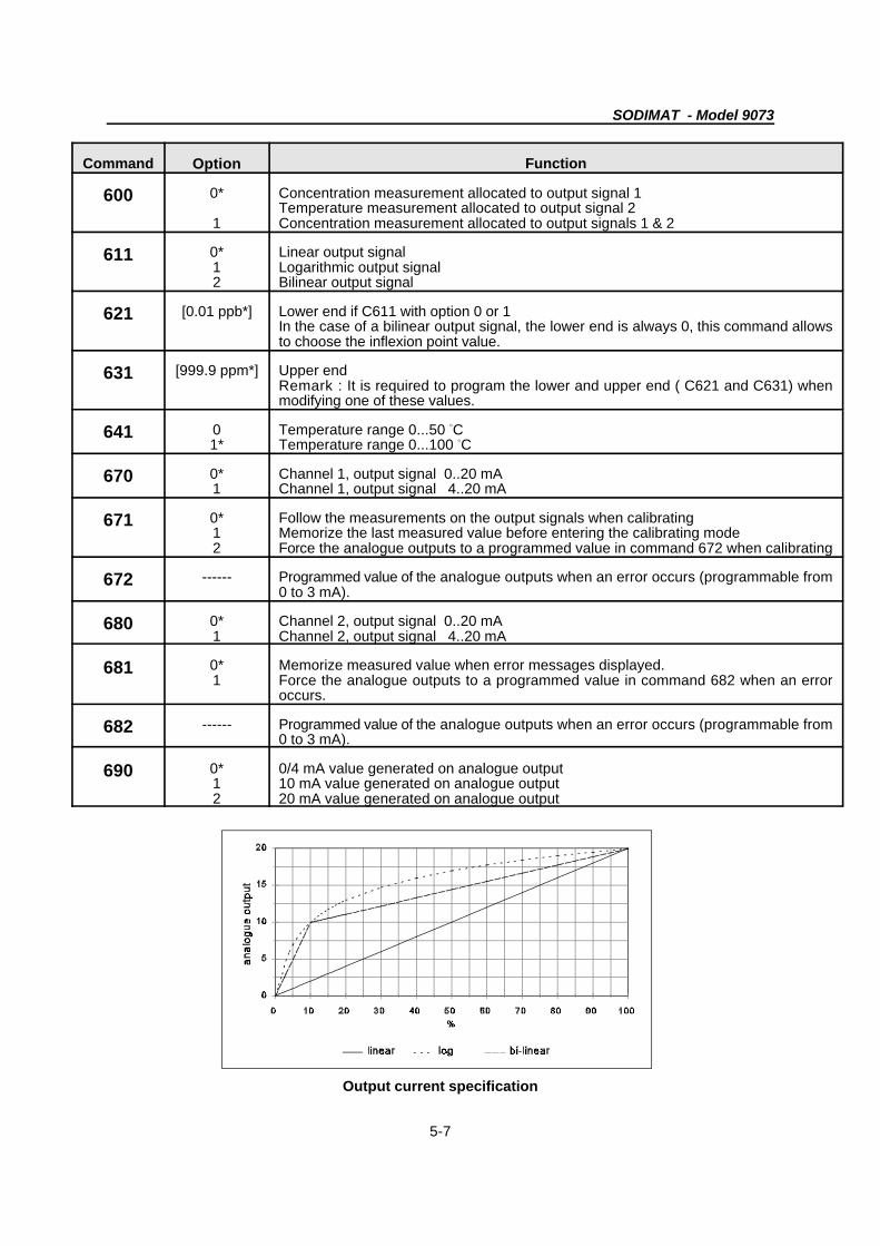
Command FunctionOption
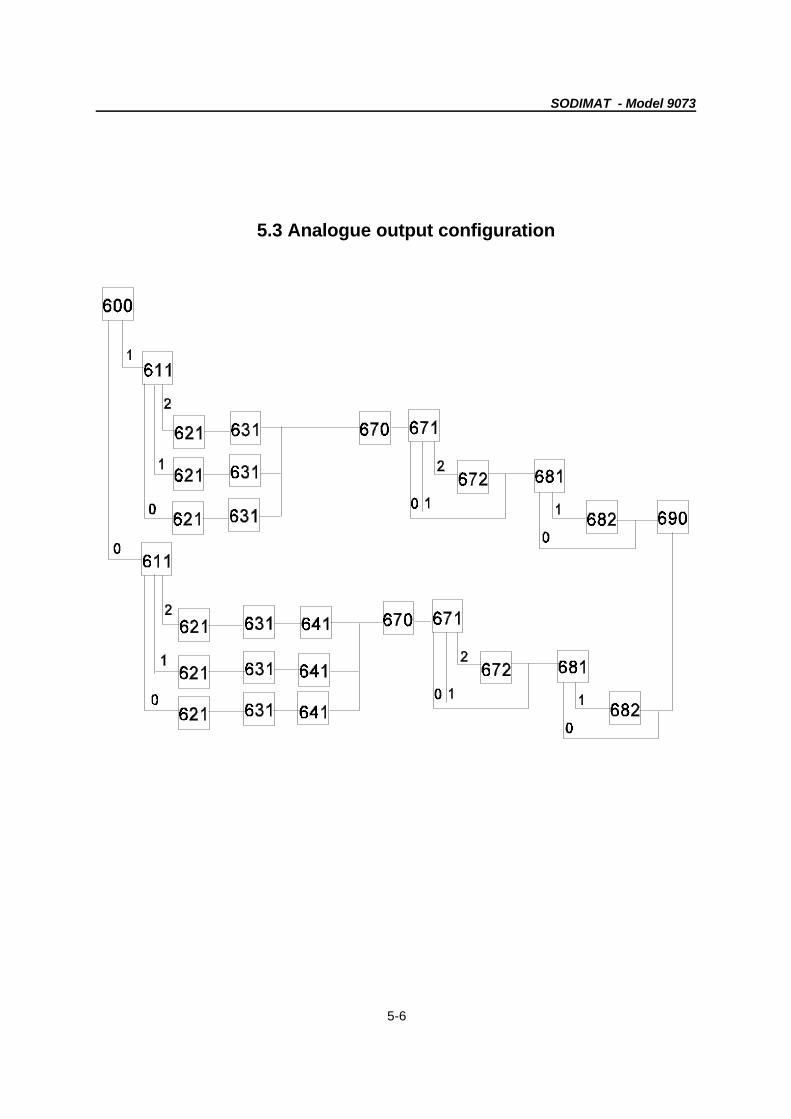
600 0* Concentration measurement allocated to output signal 1
1 Concentration measurement allocated to output signals 1 & 2Temperature measurement allocated to output signal 2
611 0* Linear output signal1 Logarithmic output signal2 Bilinear output signal
621 [0.01 ppb*] Lower end if C611 with option 0 or 1In the case of a bilinear output signal, the lower end is always 0, this command allowsto choose the inflexion point value.
631 [999.9 ppm*] Upper endRemark : It is required to program the lower and upper end ( C621 and C631) whenmodifying one of these values.
641 0 Temperature range 0...50 C1* Temperature range 0...100 C
B
B
670 0* Channel 1, output signal 0..20 mA1 Channel 1, output signal 4..20 mA
671 0* Follow the measurements on the output signals when calibrating1 Memorize the last measured value before entering the calibrating mode2 Force the analogue outputs to a programmed value in command 672 when calibrating
672 ------ Programmed value of the analogue outputs when an error occurs (programmable from0 to 3 mA).
680 0* Channel 2, output signal 0..20 mA1 Channel 2, output signal 4..20 mA
681 0* Memorize measured value when error messages displayed.1 Force the analogue outputs to a programmed value in command 682 when an error
occurs.
682 ------ Programmed value of the analogue outputs when an error occurs (programmable from0 to 3 mA).
690 0* 0/4 mA value generated on analogue output1 10 mA value generated on analogue output2 20 mA value generated on analogue output
Output current specification

3
2
1
0
0
1
10
23
45
SODIMAT - Model 9073
5-8
5.4 Serial interface configuration

SODIMAT - Model 9073
5-9
Remark In order to receive only "one" transmission of the measurement data, select command 820(1) and print the following command : "R830".
Command FunctionOption
800 0* No transmission of alarm limits1 Transmission of S1 and S2 limits2 Transmission of the alarm system3 Transmission of the S1 and S2 limits and the alarm system
810 0* RS232 inactive1 RS232 active
820 0 Continuous transmission of measuring data1 Transmission on request only
830* ------------ Transmission of the data measurement (if C820 = 1)
840 0* 300 baud1 600 baud2 1200 baud3 2400 baud4 4800 baud5 9600 baud
* : Command accessible only via RS232. It is not displayed..
5.5 Use of the interface RS232
The following codes enable the RS232 interface. Specifications of these codes :
@ Speed in baud (Command 840)
@ 1 stop bit
@ No parity bit
@ 8 bits per word
The data are in ASCII form :
M1 : 23.00 ppm 25.0 C -360.0 mVB
The transmitter sends back the data received to allow the reception control.
TRANSFERED CONTROL OF THE SODIMAT
2 characters allow the transfered control : "@" and "!"
the "@" character transfers the control to the computer. The "!" character passes the control to the Moneckeyboard. The control transfer to a remote computer deactivates the transmitter keyboard.
SODIMAT - Model 9073
5-10
REMOTE CONTROL
If the monec is microprocessor operated, the "!" character comes before each command set with thecomputer. 4 available commands with the computer :
- W - Choose the display of a parameter (Window)
- S - Program the transmitter commands (Set)
- R - Read the programmed value of the parameter (Read)
- Q - Reset remote alarm system
NOTE : The command characters (W, S, R, Q) can be written in capital or small letters.
"WINDOW" COMMAND
This command plays the same role as the scroll keys on the Monec keyboard.
4 options available :
- ":W0 ENTER": selects the value of the concentration measured
- ":W1 ENTER": selects the temperature value
- ":W2 ENTER": selects the potential value
- ":W3 ENTER": selects the flowrate measured
"SET" COMMAND
The SET command allows the Monec remote programming :
":S command number, selected value ENTER"
Select an integer value for "SELECTION" type argument (command 51, 201, 211...).
Example: :S1,1"ENTER""
For arguments type "limits, upper/lower end, ...", select a real value with the point and the exponent '"E" : 10basis exponent).
Example: ":S506,+5.000E-6"ENTER""
CAUTION : A space corresponds to the ENTER key.

SODIMAT - Model 9073
5-11
"READ" COMMAND
The READ command allows the reading of a parameter programmed value. You could read :!
":R, command number"
The Monec displays the programmed arguments for the specific command.
"RESET" COMMAND
The RESET command allows the alarm system reset with "Q"".
0 1
2
Code
SODIMAT - Model 9073
This command is not displayed1
5-12
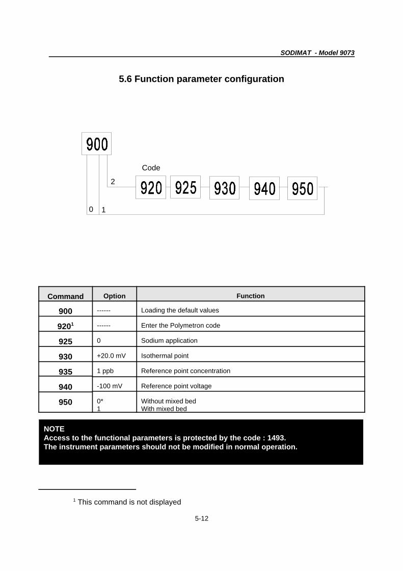
NOTEAccess to the functional parameters is protected by the code : 1493.The instrument parameters should not be modified in normal operation.
5.6 Function parameter configuration
Command Option Function
900 ------ Loading the default values
9201 ------ Enter the Polymetron code
925 0 Sodium application
930 +20.0 mV Isothermal point
935 1 ppb Reference point concentration
940 -100 mV Reference point voltage
950 0* Without mixed bed1 With mixed bed
SODIMAT - Model 9073
6-1
REMARKAny result (calibration or measurement) is always brought back to the reference temperature(25 EEC, 77 EEF). If the sample temperature is different from the reference temperature, it isrequired to execute a manual or automatic temperature compensation.
NOTESee chapter 5 for Programming the analyser.
Chapter 6 : Calibrating the instrument
6.1 Calibration of the flowmeter
Calibrate the flowmeter before any other operation. It is also required to adjust the flowmeasurement which has been already factory-preadjusted but which should be adjusted onsite.Procede as follows :
- Measure the output flowrate (weighing of water to drain during 10 minutes, for instance)- Enter the programming mode and scroll up to command C101 : flowrate calibration, enterthe value. (See chapter 5 : programming for further information).
6.2 Calibration of the temperature sensor
The temperature sensor is located 1 cm under the measurement electrode. It is factory-preadjusted but needs to be calibrated in the sample on site. This calibration must berealised before the sodium measurement calibration.To execute this calibration remove carefully the measurement electrode and replace it by aprecision thermometer in order to obtain a reference value.
6.2.1 Temperature automatic compensation
The sensor measures continuously the sample temperature. The concentration values areautomatically calculated according to the reference temperature (25EC) by a pre-programmed law in the transmitter.
The procedure is as follows (you can also check the commands in Chapter 5) :
SODIMAT - Model 9073
6-2
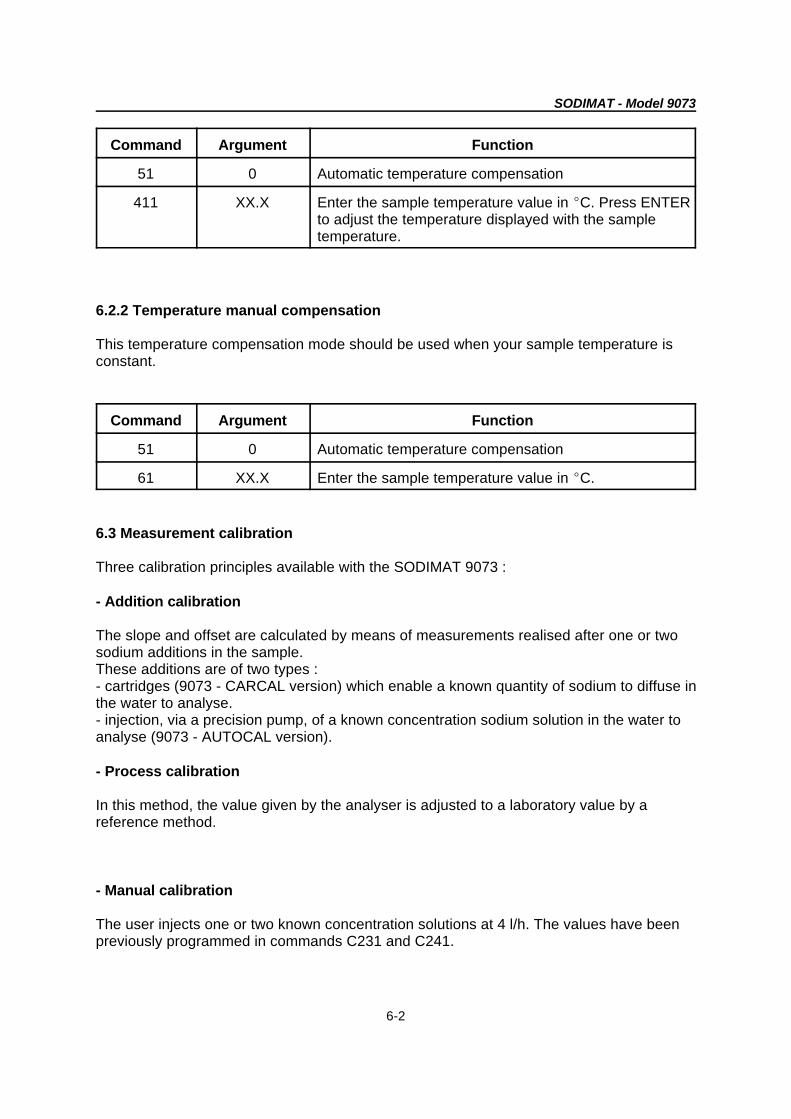
Command Argument Function
51 0 Automatic temperature compensation
411 XX.X Enter the sample temperature value in EC. Press ENTERto adjust the temperature displayed with the sampletemperature.
6.2.2 Temperature manual compensation
This temperature compensation mode should be used when your sample temperature isconstant.
Command Argument Function
51 0 Automatic temperature compensation
61 XX.X Enter the sample temperature value in EC.
6.3 Measurement calibration
Three calibration principles available with the SODIMAT 9073 :
- Addition calibration
The slope and offset are calculated by means of measurements realised after one or twosodium additions in the sample.These additions are of two types :- cartridges (9073 - CARCAL version) which enable a known quantity of sodium to diffuse inthe water to analyse.- injection, via a precision pump, of a known concentration sodium solution in the water toanalyse (9073 - AUTOCAL version).
- Process calibration
In this method, the value given by the analyser is adjusted to a laboratory value by areference method.
- Manual calibration
The user injects one or two known concentration solutions at 4 l/h. The values have beenpreviously programmed in commands C231 and C241.
SODIMAT - Model 9073
6-3
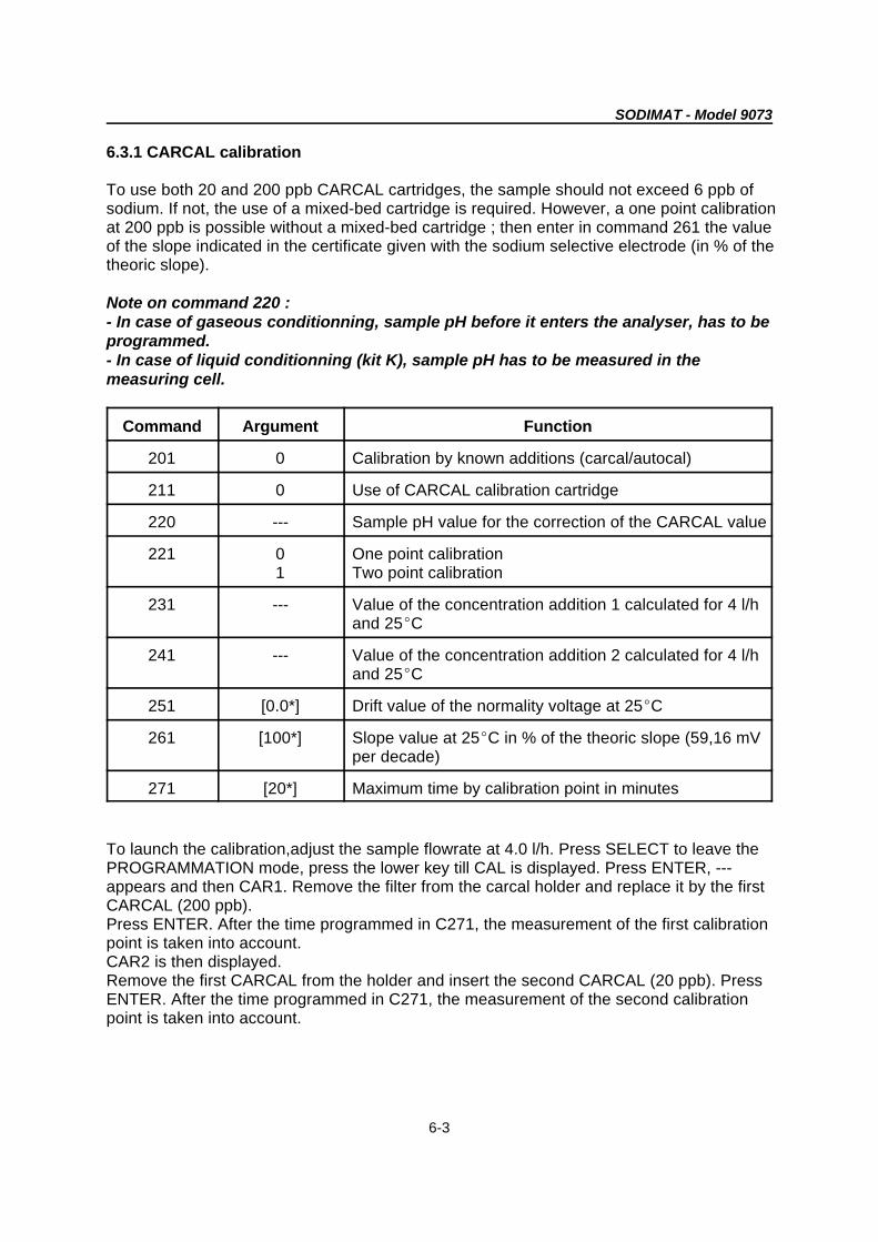
6.3.1 CARCAL calibration
To use both 20 and 200 ppb CARCAL cartridges, the sample should not exceed 6 ppb ofsodium. If not, the use of a mixed-bed cartridge is required. However, a one point calibrationat 200 ppb is possible without a mixed-bed cartridge ; then enter in command 261 the valueof the slope indicated in the certificate given with the sodium selective electrode (in % of thetheoric slope).
Note on command 220 : - In case of gaseous conditionning, sample pH before it enters the analyser, has to beprogrammed.- In case of liquid conditionning (kit K), sample pH has to be measured in themeasuring cell.
Command Argument Function
201 0 Calibration by known additions (carcal/autocal)
211 0 Use of CARCAL calibration cartridge
220 --- Sample pH value for the correction of the CARCAL value
221 0 One point calibration1 Two point calibration
231 --- Value of the concentration addition 1 calculated for 4 l/hand 25EC
241 --- Value of the concentration addition 2 calculated for 4 l/hand 25EC
251 [0.0*] Drift value of the normality voltage at 25EC
261 [100*] Slope value at 25EC in % of the theoric slope (59,16 mVper decade)
271 [20*] Maximum time by calibration point in minutes
To launch the calibration,adjust the sample flowrate at 4.0 l/h. Press SELECT to leave thePROGRAMMATION mode, press the lower key till CAL is displayed. Press ENTER, ---appears and then CAR1. Remove the filter from the carcal holder and replace it by the firstCARCAL (200 ppb).Press ENTER. After the time programmed in C271, the measurement of the first calibrationpoint is taken into account.CAR2 is then displayed.Remove the first CARCAL from the holder and insert the second CARCAL (20 ppb). PressENTER. After the time programmed in C271, the measurement of the second calibrationpoint is taken into account.
SODIMAT - Model 9073
6-4
Warning : do not forget to put back the filter after the calibration iscompleted.
Note 1 :- Pressing SELECT interrups the calibration- Pressing ENTER validates the measurement before the required time (if the measurementis considered stable).Note 2 :- C251 and C261 permit to control the new offset and slope values.- It is possible to take a note of these values in Appendix B to check the electrodeevolution.
The analyser is then able to calculate the new offset and slope.If any big difference after the calculation compared to the theoric values, the following errormessage is displayed.
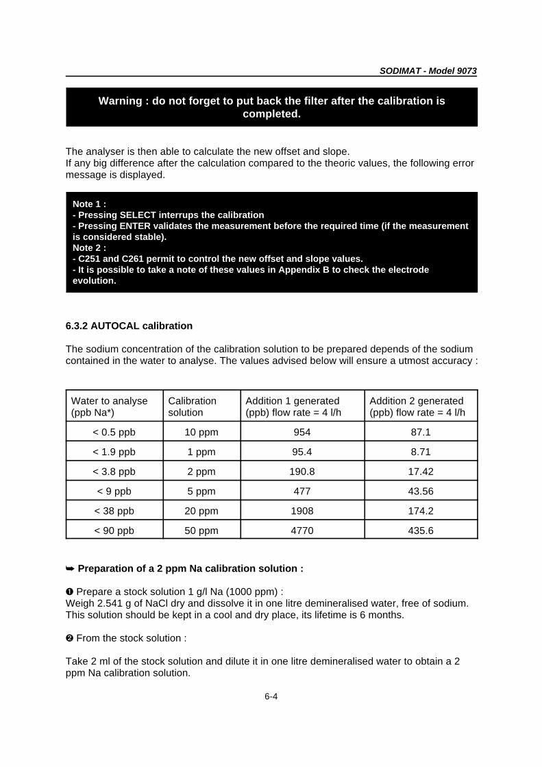
6.3.2 AUTOCAL calibration
The sodium concentration of the calibration solution to be prepared depends of the sodiumcontained in the water to analyse. The values advised below will ensure a utmost accuracy :
Water to analyse Calibration Addition 1 generated Addition 2 generated(ppb Na*) solution (ppb) flow rate = 4 l/h (ppb) flow rate = 4 l/h
< 0.5 ppb 10 ppm 954 87.1
< 1.9 ppb 1 ppm 95.4 8.71
< 3.8 ppb 2 ppm 190.8 17.42
< 9 ppb 5 ppm 477 43.56
< 38 ppb 20 ppm 1908 174.2
< 90 ppb 50 ppm 4770 435.6
( Preparation of a 2 ppm Na calibration solution :
ì Prepare a stock solution 1 g/l Na (1000 ppm) :Weigh 2.541 g of NaCl dry and dissolve it in one litre demineralised water, free of sodium.This solution should be kept in a cool and dry place, its lifetime is 6 months.
í From the stock solution :
Take 2 ml of the stock solution and dilute it in one litre demineralised water to obtain a 2ppm Na calibration solution.

SODIMAT - Model 9073
6-5
Warnings :
- It is required to use a magnetic stirrer for a better stirring when preparing the stocksolution.
- Make sure anything used with the solutions are sodium-free : beaker, water, stirrer. (Frequent rinsing with demineralised water).
- The accuracy of the Sodium concentration in the calibration solution depends on theweighing instruments, their accuracy in the measuring range used should have beenchecked.
If your sample contains very low quantities of sodium (< 0,5 ppb), an electrodedesensitization may occur. It is then required to increase the calibration frequency so thatthe additions will ensure the reactivation of the electrode.
Water to analyze (ppb Na ) Required calibration frequency (C217)+
< 0.2 ppb 48 H
between 0.2 and 0.5 ppb 72 H
Water to analyze (ppb Na ) Required calibration time per point+
(C271)
< 0.5 ppb 25-30 minutes
> 0.5 ppb 20-25 minutes
Programming :
Command Argument Function
201 0 Calibration by known additions (carcal/cal sol)
211 1 Use of calibration solution
215 0 Desactivate the automatic calibration mode1 Activate the automatic calibration mode
217 --- Time between two automatic calibrations
221 0 One point calibration1 Two point calibration

SODIMAT - Model 9073
6-6
Note 1 : - Pressing SELECT interrups the calibration- Pressing ENTER validates the measurement before the required time (if the measurementis considered stable).
Note 2 : - C251 and C261 permit to control the new offset and slope values.- It is possible to take a note of these values in Appendix B to check the electrodeevolution.
223 0 Low frequency of the calibration pump for the calibration
1 High frequency of the calibration pump for the calibrationwith one point solution
with one point solution
225 --- Concentration value of the calibration solution
231 --- Value of the concentration addition 1 calculated for 4 l/hand 25EC. The value taken into account is the value ofthe real addition measured by the instrument
241 --- Value of the concentration addition 2 calculated for 4 l/hand 25EC. The value taken into account is the value ofthe real addition measured by the instrument
251 [0.0*] Drift value of the reference potential at 25 EC
261 [100*] Slope value at 25 EC in % of the theoric slope (59,16 mVper decade)
271 [20*] Maximum time by calibration point in minutes
Calibration procedure
a) Automatic desactivated calibration (C215 = 0) :
To launch the calibration manually, press SELECT to leave the programmation mode, pressthe lower key till CAL is displayed. Press ENTER, SOL1 appears (first addition), pressENTER to validate. The pump injects the calibration solution in the sample.After the time programmed in C271, the measurement of the first calibration point is takeninto account. SOL2 is displayed. Press ENTER.After the time programmed in C271, the measurement in C271 of the second calibrationpoint is taken into account.
The analyser is then able to calculate the new offset and slope. If any big difference appearsafter the calculation compared to the theoric values, one of the error messages ER24/25/26is displayed.
b) Automatic activated calibration (C215 = 1)
To launch the calibration, press SELECT to leave the programmation mode. The analyserexecutes automatically the calibration cycle with a frequency programmed in C217.
SODIMAT - Model 9073
6-7
Note 1 : - Pressing SELECT interrups the calibration- Pressing ENTER validates the measurement before the required time (if the measurementis considered stable).
Note 2 : - C251 and C261 permit to control the new offset and slope values.- It is possible to take a note of these values in Appendix B to check the electrodeevolution.
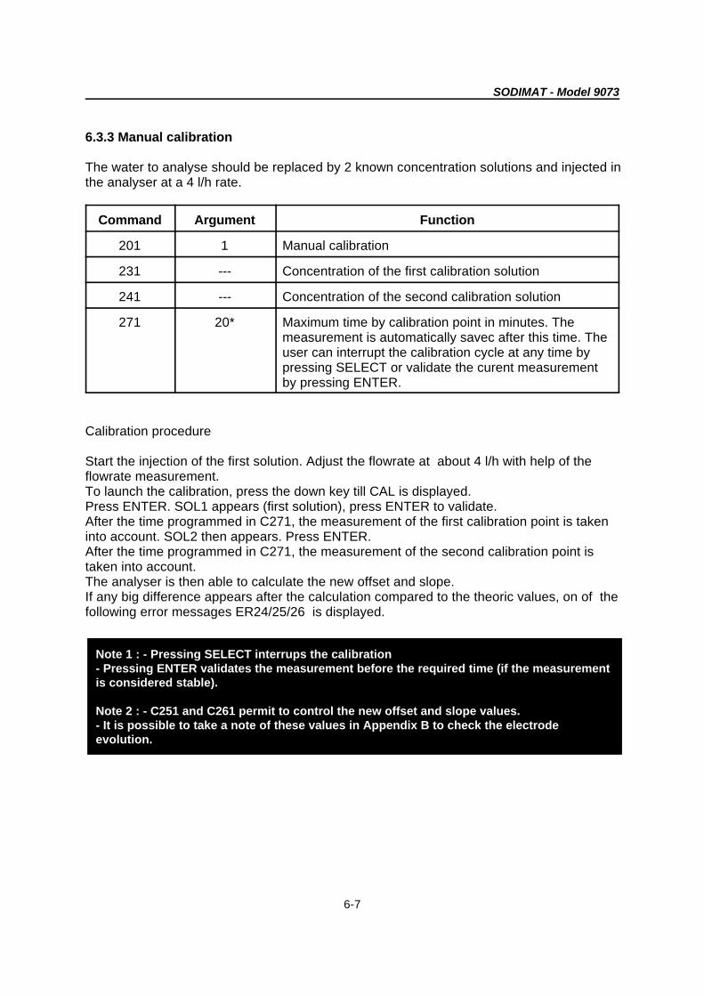
6.3.3 Manual calibration
The water to analyse should be replaced by 2 known concentration solutions and injected inthe analyser at a 4 l/h rate.
Command Argument Function
201 1 Manual calibration
231 --- Concentration of the first calibration solution
241 --- Concentration of the second calibration solution
271 20* Maximum time by calibration point in minutes. Themeasurement is automatically savec after this time. Theuser can interrupt the calibration cycle at any time bypressing SELECT or validate the curent measurementby pressing ENTER.
Calibration procedure
Start the injection of the first solution. Adjust the flowrate at about 4 l/h with help of theflowrate measurement.To launch the calibration, press the down key till CAL is displayed.Press ENTER. SOL1 appears (first solution), press ENTER to validate.After the time programmed in C271, the measurement of the first calibration point is takeninto account. SOL2 then appears. Press ENTER.After the time programmed in C271, the measurement of the second calibration point istaken into account.The analyser is then able to calculate the new offset and slope.If any big difference appears after the calculation compared to the theoric values, on of thefollowing error messages ER24/25/26 is displayed.
SODIMAT - Model 9073
6-8
Note 1 : - Pressing SELECT interrups the calibration- Pressing ENTER validates the measurement before the required time (if the measurementis considered stable).
Note 2 : - C251 and C261 permit to control the new offset and slope values.- It is possible to take a note of these values in Appendix B to check the electrodeevolution.
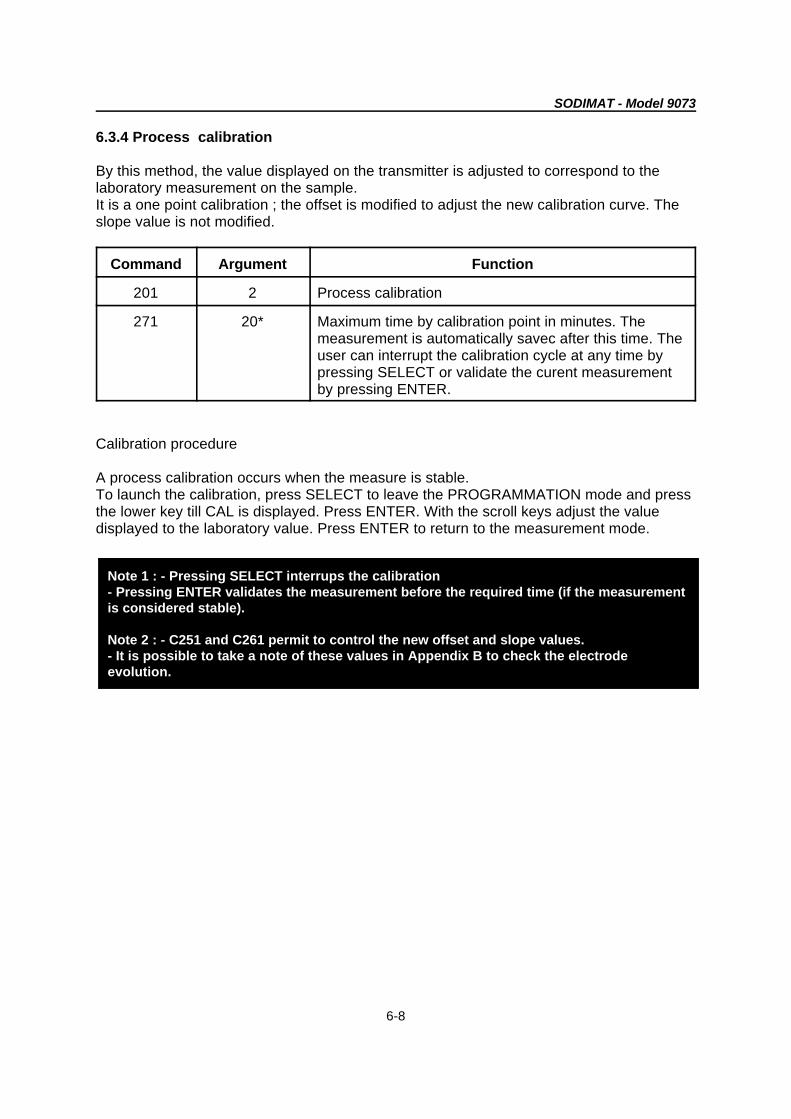
6.3.4 Process calibration
By this method, the value displayed on the transmitter is adjusted to correspond to thelaboratory measurement on the sample.It is a one point calibration ; the offset is modified to adjust the new calibration curve. Theslope value is not modified.
Command Argument Function
201 2 Process calibration
271 20* Maximum time by calibration point in minutes. Themeasurement is automatically savec after this time. Theuser can interrupt the calibration cycle at any time bypressing SELECT or validate the curent measurementby pressing ENTER.
Calibration procedure
A process calibration occurs when the measure is stable.To launch the calibration, press SELECT to leave the PROGRAMMATION mode and pressthe lower key till CAL is displayed. Press ENTER. With the scroll keys adjust the valuedisplayed to the laboratory value. Press ENTER to return to the measurement mode.
SODIMAT - Model 9073
7-1
Chapter 7 : Maintenance
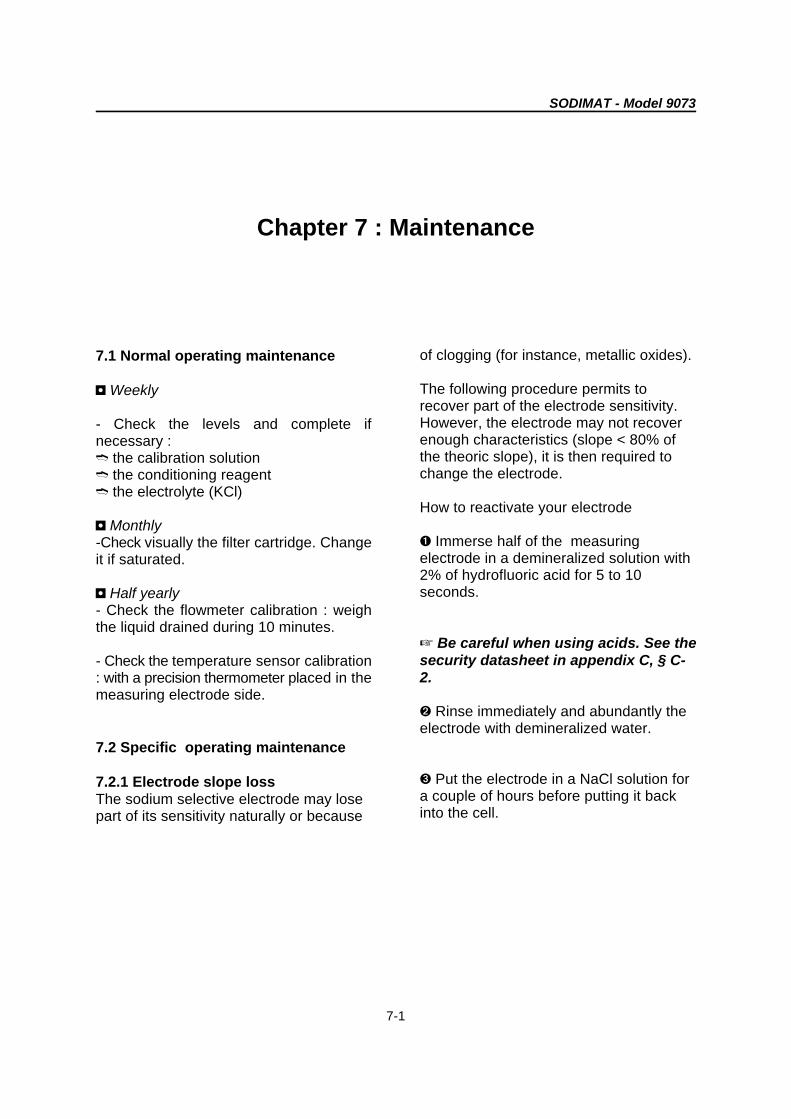
7.1 Normal operating maintenance
3 Weekly
- Check the levels and complete ifnecessary :/ the calibration solution/ the conditioning reagent/ the electrolyte (KCl)
3 Monthly-Check visually the filter cartridge. Changeit if saturated.
3 Half yearly- Check the flowmeter calibration : weighthe liquid drained during 10 minutes.
- Check the temperature sensor calibration: with a precision thermometer placed in themeasuring electrode side.
7.2 Specific operating maintenance
7.2.1 Electrode slope lossThe sodium selective electrode may losepart of its sensitivity naturally or because
of clogging (for instance, metallic oxides).
The following procedure permits torecover part of the electrode sensitivity.However, the electrode may not recoverenough characteristics (slope < 80% ofthe theoric slope), it is then required tochange the electrode.
How to reactivate your electrode
ì Immerse half of the measuringelectrode in a demineralized solution with2% of hydrofluoric acid for 5 to 10seconds.
L Be careful when using acids. See thesecurity datasheet in appendix C, § C-2.
í Rinse immediately and abundantly theelectrode with demineralized water.
î Put the electrode in a NaCl solution fora couple of hours before putting it backinto the cell.

SODIMAT - Model 9073
8-1
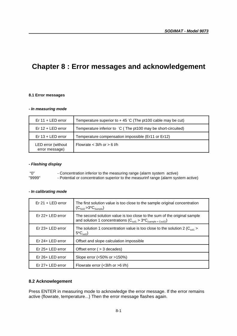
Chapter 8 : Error messages and acknowledgement
8.1 Error messages
- In measuring mode
Er 11 + LED error Temperature superior to + 45 C (The pt100 cable may be cut)B
Er 12 + LED error Temperature inferior to C ( The pt100 may be short-circuited)B
Er 13 + LED error Temperature compensation impossible (Er11 or Er12)
LED error (without Flowrate < 3l/h or > 6 l/herror message)
- Flashing display
“0” - Concentration inferior to the measuring range (alarm system active)"9999" - Potential or concentration superior to the measurinf range (alarm system active)
- In calibrating mode
Er 21 + LED error The first solution value is too close to the sample original concentration(C >3*C )Sol2 Sample
Er 22+ LED error The second solution value is too close to the sum of the original sampleand solution 1 concentrations (C > 3*C )sol1 (sample + Csol2)
Er 23+ LED error The solution 1 concentration value is too close to the solution 2 (C >sol1
5*C )sol2
Er 24+ LED error Offset and slope calculation impossible
Er 25+ LED error Offset error ( > 3 decades)
Er 26+ LED error Slope error (<50% or >150%)
Er 27+ LED error Flowrate error (<3l/h or >6 l/h)
8.2 Acknowlegement
Press ENTER in measuring mode to acknowledge the error message. If the error remainsactive (flowrate, temperature...) Then the error message flashes again.


SODIMAT - Model 9073
9-1
Chapter 9 :Troubleshootings, causes and solutions
WARNING !
Never attempt servicing before disconnecting the instrument from the mainpower line.
MALFUNCTION POSSIBLE CAUSE REMEDIES
No indication No power ; instrument is not Check for power, then check ifNo LED is illuminated connected correctly connected properlyNo LCD backlighting
Defective fuse Check fuse
Instrument's power supply set for Check jumpers on power-supply boardwrong line voltage for correct voltage settings
Ribbon cable connecting power with Check that the ribbon plugs areCPU board not properly plugged in properly plugged in.
Connection between CPU board and Secure plug connectionsmeasurement module loose
Short circuit in power-supply board Visually check power-supply board forshorts
Hardware is defective Call the Service Technician
LCD displays undefined characters Malfunctionning CPU board or Using the Instruction manual, programprocessor the instrument to load the default
values
CPU hardware RESET the instrument by temporarilyinterrupting the power (5-10 secs.)
Call the Service Technician
Keyboard does not operate ; all keys CPU malfunctioinning, external Sequentially press the keys UP,are inactive interferences DOWN, ENTER, SELECT.. If there is
no response, RESET the instrumentby temporarily interrupting the power(5-10 seconds.). Check each keyagain. If there is no change, call theService Technician.

SODIMAT - Model 9073
9-2
Measurement not correct Instrument not programmed properly Check the programming parameters.
Reprogram the instrument checking itcorresponds to the probecharacteristics
System with probe not calibrated Calibrate the system with probeproperly connected.
Probe not connected properly Check the connection
Probe not operating properly, may be Check the probe visually. Check theimpossible with this application probe specifications with the
application
CPU board malfunctionning If problem persists, call the ServiceTechnician.
Measurement not stable Probe malfunctionning Check the probe
Probe not connected properly Check the connection
Interferences Check there in no chemical, external
Cable shield not correctly connected sourcetemperature or pressure interference
Check and connect again.
Lack of conditioning reagent Add reagent
Lack of electrolyte in the reference Add electrolyte .electrode
Temperature measurement not Probe not properly connected Check itcorrect
Temperature not calibrated Calibrate for temperature
CPU board malfunctionning If problem persists, call the ServiceTechnician.
Reading blocked, can not be changed CPU board and/or other part of Check the probe is correctly connectedtransmitter
Zeroing
Program the instrument again
If it still does not work : reset andswitch off the instrument
Program again
If problem persists, call the ServiceTechnician.
ERROR displayed Probe malfunctionning Check for dirt or electrode
Probe not connected properly Check the connections
No contact between the probe and Check the sample flowratethe sample
CPU board malfunctionning If problem persists, call the ServiceTechnician.
Relay not energised Instrument was programmed Check whether the correct relayincorrectly parameters and setpoints have been
programmed.
Hardware is defective Check that the programmed setpointsare compatible with the programmedmeasuring range.
SODIMAT - Model 9073
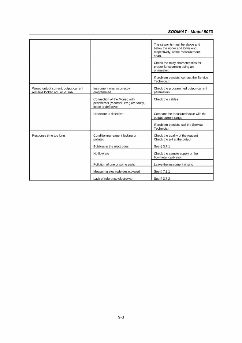
9-3
The setpoints must be above andbelow the upper and lower end,respectively, of the measurementspan.
Check the relay characteristics forproper functionning using anohmmeter.
If problem persists, contact the ServiceTechnician.
Wrong output current, output current Instrument was incorrectly Check the programmed output-currentremains locked at 0 or 20 mA programmed parameters
Connection of the Monec with Check the cablesperipherals (recorder, etc.) are faulty,loose or defective.
Hardware is defective Compare the measured value with theoutput-current range
If problem persists, call the ServiceTechnician
Response time too long Conditioning reagent lacking or Check the quality of the reagentpolluted Check the pH at the output
Bubbles in the electrodes See § 3.7.1
No flowrate Check the sample supply or theflowmeter calibration
Pollution of one or some parts Leave the instrument rinsing
Measuring electrode desactivated See § 7.2.1
Lack of reference electrolyte See § 3.7.2
SODIMAT - Model 9073
10-1
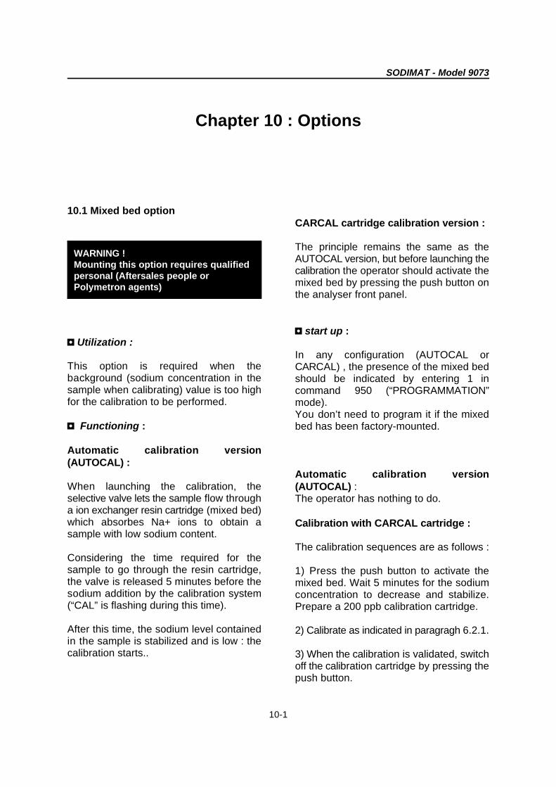
WARNING !Mounting this option requires qualifiedpersonal (Aftersales people orPolymetron agents)
Chapter 10 : Options
10.1 Mixed bed option
3 Utilization :
This option is required when thebackground (sodium concentration in thesample when calibrating) value is too highfor the calibration to be performed.
3 Functioning :
Automatic calibration version(AUTOCAL) :
When launching the calibration, theselective valve lets the sample flow througha ion exchanger resin cartridge (mixed bed)which absorbes Na+ ions to obtain asample with low sodium content.
Considering the time required for thesample to go through the resin cartridge,the valve is released 5 minutes before thesodium addition by the calibration system(“CAL” is flashing during this time).
After this time, the sodium level containedin the sample is stabilized and is low : thecalibration starts..
CARCAL cartridge calibration version : The principle remains the same as theAUTOCAL version, but before launching thecalibration the operator should activate themixed bed by pressing the push button onthe analyser front panel.
3 start up :
In any configuration (AUTOCAL orCARCAL) , the presence of the mixed bedshould be indicated by entering 1 incommand 950 (“PROGRAMMATION”mode).You don’t need to program it if the mixedbed has been factory-mounted.
Automatic calibration version(AUTOCAL) :The operator has nothing to do.
Calibration with CARCAL cartridge :
The calibration sequences are as follows :
1) Press the push button to activate themixed bed. Wait 5 minutes for the sodiumconcentration to decrease and stabilize.Prepare a 200 ppb calibration cartridge.
2) Calibrate as indicated in paragragh 6.2.1.
3) When the calibration is validated, switchoff the calibration cartridge by pressing thepush button.
SODIMAT - Model 9073
10-2
3 maintenance : Replacing the mixed bed cartridge (see
Check frequently (once a month) the resin.The colour of the resin indicates itsconsumption :
- Black or dark green : resin active- Brown or orange : resin exhausted
When a resin is exhausted, the sodiumdecrease is longer and the backgroundsodium level obtained may remain too high.
reference in appendix A) :
Replacing the mixed bed cartridge is easyand quick :- switch off the analyser- turn off the sample inlet (turn the adjustingvalve clockwise)- Disconnect the input and output tubes- Open the clamping collar and remove theold cartridge- Mount the new cartridge (no particularorientation to respect)- Proceed in the reverse order for thereassembling.

SODIMAT - Model 9073
10-3
Figure 10-1 : Mixed bed for CARCAL version
1 : Control push button 3 : Mixed bed control valve
2 : Mixed bed cartridge
SODIMAT - Model 9073
10-4
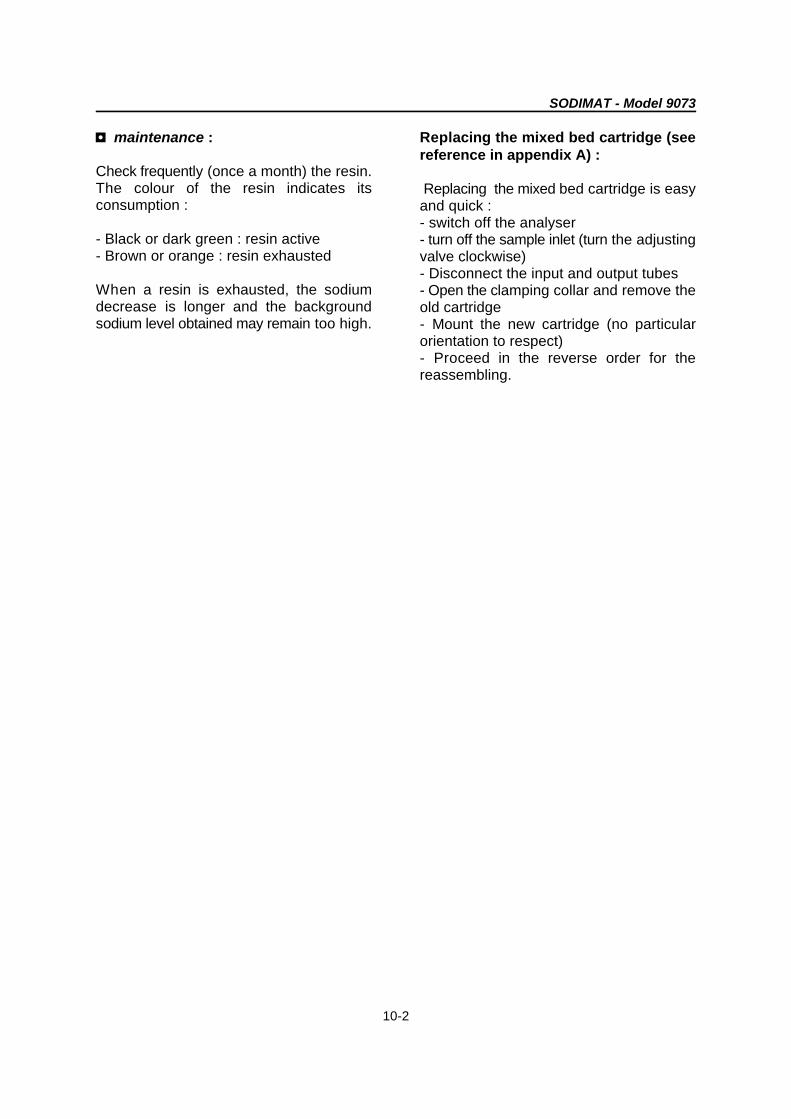
Figure 10-2 : Mixed bed for AUTOCAL version
1 : Mixed bed cartridge 2 : Control valve
SODIMAT - Model 9073
10-5
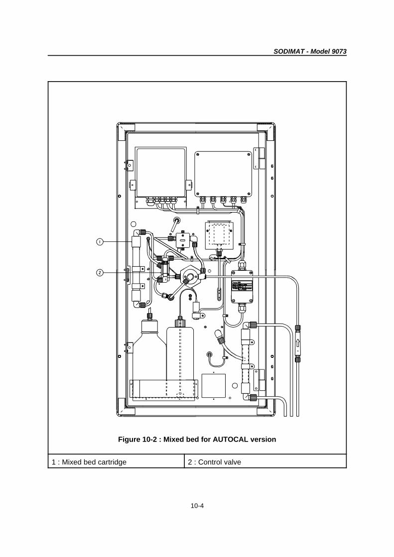
10.2 Liquid conditioning option (Kit K)
10.2.1 Generality
Figure 10-3a : kit K + AUTOCAL principle diagram
1 : Conditioning reagent 3 : Calibration solution
2 : Conditioning pump 4 : Calibration pump
Figure 10-3b : kit K + CARCAL principle diagram
1 : conditioning reagent 3 : CARCAL calibration cartridge
2 : Conditioning pump

SODIMAT - Model 9073
10-6
The cassette is made of Delrin ; it issusceptible to chemical attack bystrong acids and bases.
This option is required when the gaseous Starting up :conditioning is unsufficient to reach highpH (>10) necessary for a correct sodium The conditioning reagent injection startsmeasurement (H+ ion interferences). with the pump when pressing the push
This problem occurs when the sample is automatically.acid and acting like a buffer (for instance,cation exchanger resins).
This option solves the problem by ensuringan extremely efficient liquid conditioningwhich permits to obtain the necessary pHvalue.
Functioning :
The conditioning reagent is pumped by aperistaltic pump from the bottle suppliedwith the kit. The reagent is then injected inthe sample circuit.
Ethanolamine and ammoniac are therequired conditioning reagents.
10.2.2 Putting into service
ì Preparation of the ethanolaminereagents
- Dilute ethanolamine (30% concentrated,quality “per analysis”) with demineralisedwater with a low sodium content.After starting up the liquid conditioning (seeexplanation below) measure the pH at theoutput. Check the pH value corresponds tothe following requirements :
Sodium concentration output pH[Na+] of the sample
> 10 ppb > 9
> 1 ppb >10
If the pH is unsufficient, increase theethanolamine concentration up to 50%.
button. The pump priming is done
í Pump tubing and cassette
The peristaltic pump is a one-channel unitpowered by a synchronous motor. Thedosage is adjustable by selectingappropriately sized pump tubing. The pumpis designed to handle small rates of flowaccurately and reproducibly, thus making itespecially suitable for very demandingliquid-dosing tasks. It turns at a rate of 20turns per minute.
The cassette is adjustable and of plug-in-type ; the bottom part (tubing bed) isequipped with two machined notches whichposition the flexible tubings securely inorder to prevent excessive stretching orslacking.
The pump tubing should be tightenedcorrectly on the rollers to avoid any samplereturn in the conditioning bottle.
SODIMAT - Model 9073
10-7
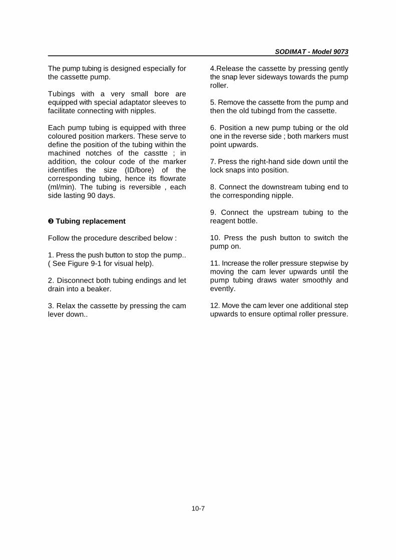
The pump tubing is designed especially for 4.Release the cassette by pressing gentlythe cassette pump. the snap lever sideways towards the pump
Tubings with a very small bore areequipped with special adaptator sleeves to 5. Remove the cassette from the pump andfacilitate connecting with nipples. then the old tubingd from the cassette.
Each pump tubing is equipped with three 6. Position a new pump tubing or the oldcoloured position markers. These serve to one in the reverse side ; both markers mustdefine the position of the tubing within the point upwards. machined notches of the casstte ; inaddition, the colour code of the marker 7. Press the right-hand side down until theidentifies the size (ID/bore) of the lock snaps into position.corresponding tubing, hence its flowrate(ml/min). The tubing is reversible , each 8. Connect the downstream tubing end toside lasting 90 days. the corresponding nipple.
î Tubing replacement
Follow the procedure described below :
1. Press the push button to stop the pump..( See Figure 9-1 for visual help).
2. Disconnect both tubing endings and letdrain into a beaker.
3. Relax the cassette by pressing the camlever down..
roller.
9. Connect the upstream tubing to thereagent bottle.
10. Press the push button to switch thepump on.
11. Increase the roller pressure stepwise bymoving the cam lever upwards until thepump tubing draws water smoothly andevently.
12. Move the cam lever one additional stepupwards to ensure optimal roller pressure.
SODIMAT - Model 9073
10-8
Figure 10-4 : Changing the pump tubing

SODIMAT - Model 9073
10-9
Figure 10-5 : Liquid conditioning AUTOCAL version - front view
1 : Conditioning reagent 4 : Suction tubing
2 : Pressure tubing 5 : Push button for the conditioning pumpcontrol
3 : Conditioning pump
SODIMAT - Model 9073
10-10
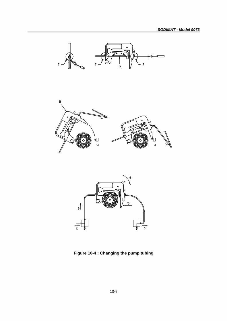
Figure 10-6 : Liquid conditioning AUTOCAL version - rear view
1 : Push button for conditioning pump 4 : Conditioning reagentcontrol
2 : Suction tubing 5/6 : Pressure tubing
3 : Pump 7 : Injection tee for the conditioning reagent

SODIMAT - Model 9073
10-11
Figure 10-7 : Liquid conditioning CARCAL version - Front view
1 : Conditioning reagent 4 : Suction tubing
2 : Pressure tubing 5 : Push button for the conditioning pumpcontrol
3 : Pump

SODIMAT - Model 9073
10-12
Figure 10-8 : Liquid conditioning CARCAL version - Rear view
1 : Push button for conditioning pump 4 : Conditioning reagentcontrol
2 : Suction pipe 5 : Pressure tubing
3 : Pump 6 : Injection tee for the conditioning reagent


SODIMAT - Model 9073
A1-1
Appendix A : Spare parts list
Designation Reference
2-year operation kit 09073=A=8000
FLOW METER
Flow rate controller 09073=A=9803
Valve 696=146=001
MEASUREMENT
Reference electrode 125=020=003
Measuring electrode 125=010=004
Cell 09073=A=9801
Temperature sensor 09073=C=0035
Transmitter 08941=A=0000
Measurement preamplifier 08350=A=8000
fitting for electrolyte supply 359016,00020
Electrolyte container cap 09073=A=0042
KCL 3 M reference electrolyte, 1 litre bottle 363140,01000
Electrode (reference or measuring) gasket 356207,00000
Temperature sensor gasket 356099,15055
Filter 363877,06000
GAZEOUS CONDITIONING
"DIPA" equipped container 09073=A=9809
Non equipped bottle 09073=A=0310
Stainless steel tubing 09073=C=0015
Stainless steel tubing gasket 359099,15055
Float 09073=C=0025

SODIMAT - Model 9073
A1-2
LIQUID CONDITIONING (KIT K)
50 Hz peristaltic pump 08810=A=7050
60 Hz peristaltic pump 08810=A=7060
Set of 6 pump tubings 590=620=025
Equipped canister 09073=A=0445
Non-equipped canister 09073=A=0440
AUTOMATIC CALIBRATION (AUTOCAL)
Calibration micro-pump 09073=A=9807
Bulkhead pipe fitting for cap 588=004=254
Injection Te 589=010=041
CALIBRATION WITH CARTRIDGES (CARCAL)
Box of CARCAL 20ppb 359090,20020
Box of CARCAL 200 ppb 359090,20200
Box of 12 filters 359090,20000
MIXED BED
Mixed bed cartridge 09073=A=0750
Valve 687=137=020
ELECTRONICS
Interface board 08941=A=4000
Interface complete 09073=A=5000
DOCUMENTATION
French manual 621=090=073
English manual 621=190=073
German manual 621=290=073
Italian manual 621=490=073
SODIMAT - Model 9073
B1-1
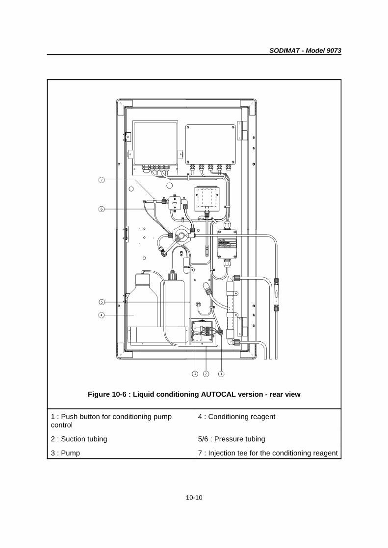
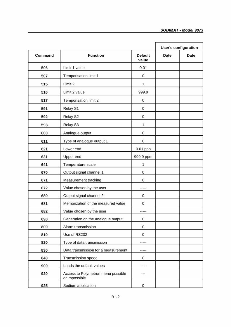
Appendix B : Configuration table for the user
User's configuration
Command Function Default Date Datevalue
51 Type of temperature compensation 0
61 Temperature value in manual -----compensation
101 Flowrate calibration -----
201 Calibration type 2
211 Use of CARCAL cartridges
215 Activates the calibration mode 0
217 Time between two automatic 168calibrations
220 pH value 7.0
221 Number of calibration points -----
223 Frequency of calibration pump 0
225 Concentration value of the calibration 2 ppmsolution
231 Concentration value of addition 1 ------
241 Concentration value of addition 2 ------
251 Drift value of the normality voltage 0.0
261 Slope value 100
271 Maximum time by calibration point 20
411 Temperature value ------
500 Activates limits 2
505 Limit 1 0
SODIMAT - Model 9073
B1-2
User's configuration
Command Function Default Date Datevalue
506 Limit 1 value 0.01
507 Temporisation limit 1 0
515 Limit 2 1
516 Limit 2 value 999.9
517 Temporisation limit 2 0
591 Relay S1 0
592 Relay S2 0
593 Relay S3 1
600 Analogue output 0
611 Type of analogue output 1 0
621 Lower end 0.01 ppb
631 Upper end 999.9 ppm
641 Temperature scale 1
670 Output signal channel 1 0
671 Measurement tracking 0
672 Value chosen by the user -----
680 Output signal channel 2 0
681 Memorization of the measured value 0
682 Value chosen by the user -----
690 Generation on the analogue output 0
800 Alarm transmission 0
810 Use of RS232 0
820 Type of data transmission -----
830 Data transmission for a measurement -----
840 Transmission speed 0
900 Loads the default values -----
920 Access to Polymetron menu possible ---or impossible
925 Sodium application 0

SODIMAT - Model 9073
B1-3
930 Isothermal point +20.0 mV
935 Reference point concentration 1 ppb
940 reference point voltage -100 mV
950 Mixed bed option 0

SODIMAT - Model 9073
C-1
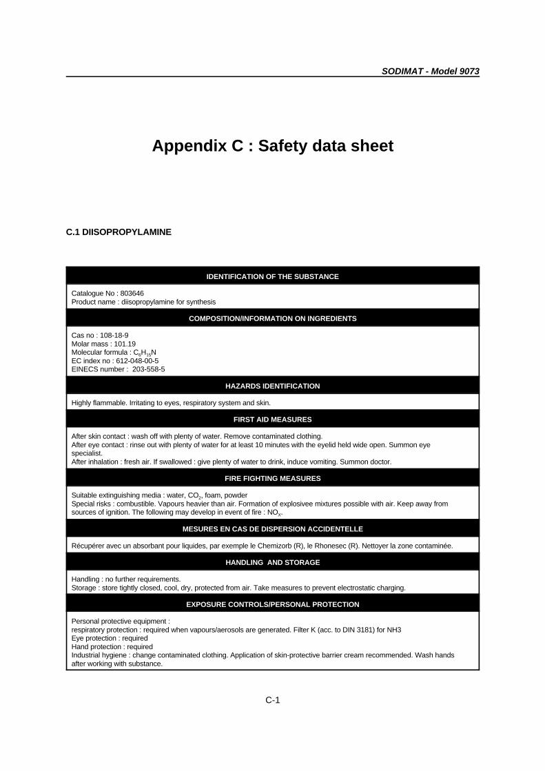
Appendix C : Safety data sheet
C.1 DIISOPROPYLAMINE
IDENTIFICATION OF THE SUBSTANCE
Catalogue No : 803646Product name : diisopropylamine for synthesis
COMPOSITION/INFORMATION ON INGREDIENTS
Cas no : 108-18-9Molar mass : 101.19Molecular formula : C H N6 15
EC index no : 612-048-00-5EINECS number : 203-558-5
HAZARDS IDENTIFICATION
Highly flammable. Irritating to eyes, respiratory system and skin.
FIRST AID MEASURES
After skin contact : wash off with plenty of water. Remove contaminated clothing.After eye contact : rinse out with plenty of water for at least 10 minutes with the eyelid held wide open. Summon eyespecialist. After inhalation : fresh air. If swallowed : give plenty of water to drink, induce vomiting. Summon doctor.
FIRE FIGHTING MEASURES
Suitable extinguishing media : water, CO , foam, powder2
Special risks : combustible. Vapours heavier than air. Formation of explosivee mixtures possible with air. Keep away fromsources of ignition. The following may develop in event of fire : NO .X
MESURES EN CAS DE DISPERSION ACCIDENTELLE
Récupérer avec un absorbant pour liquides, par exemple le Chemizorb (R), le Rhonesec (R). Nettoyer la zone contaminée.
HANDLING AND STORAGE
Handling : no further requirements.Storage : store tightly closed, cool, dry, protected from air. Take measures to prevent electrostatic charging.
EXPOSURE CONTROLS/PERSONAL PROTECTION
Personal protective equipment :respiratory protection : required when vapours/aerosols are generated. Filter K (acc. to DIN 3181) for NH3 Eye protection : requiredHand protection : requiredIndustrial hygiene : change contaminated clothing. Application of skin-protective barrier cream recommended. Wash handsafter working with substance.

SODIMAT - Model 9073
C-2
PHYSICAL AND CHEMICAL PROPERTIES
Form : liquidColour : colourlessOdour : amine-likePh value: not availableMelting temperature: -96 CB
Boiling temperature : 83 - 84 CB
Ignition temperature: 295 C DIN51794B
Flash point : - 17 C DIN51755B
Explosion limits:Lower : 1,5 vol%Upper : 8,5 vol%Vapour pressure : (20 C) 100 hPaB
Density : (20 C) 0.72 g/cmB 3
Solubility in :water (20 C) solubleB
organic solvents (20 C) solubleB
STABILITY ET REACTIVITY
Conditions to be avoided : noneSubstances to be avoided : oxidizing agents, acidsHazardous decomposition products : none information availableFurther information : hygroscopic, sensitive to air
TOXICOLOGICAL INFORMATION
Acute toxicity : DL50 (oral, rat) = 770 mg/kgFurther toxicological information :After skin contact : severe irritationsAfter eye contact : severe irritationAfter inhalation : irritations of the mucous membranes, coughing, and dyspnoea. Danger off skin absorbtion.
ECOLOGICAL INFORMATION
Do not allow to enter drinking water supplies, waste water, or soil !
DISPOSAL CONSIDERATIONS
Product : there are no uniform EC regulation for the disposal of chemicals or residues. Chemical residues generally countas special waste. The disposal of the latter is regulated in the EC member countries through corresponding laws andregulations, and in the federal republic of germany also by the individual federal states. We recommend that you contacteither the authorities in charge or approved waste disposal companies which will advise you on how to dispose of specialwaste.Packaging : disposal in accordance with local legal provisions.
The information contained herein is based on the present state of our knowledge. It characterizes the product with regard tothe appropriate safety precautions. It does not represent a guarantee of the properties of the product.

SODIMAT - Model 9073
C-3
C.2 HYDROFLUORIC ACID 40%
IDENTIFICATION OF THE SUBSTANCE
SIGMA ALDRICH product reference : 47590Product name : hydrofluoric acid 40%
COMPOSITION/INFORMATION ON INGREDIENTS
Cas no : 7664-39-3EC index no : 009-003-00-1
HAZARDS IDENTIFICATION
Highly toxic by inhalation, contact with skin and ingestion. Provokes severe burns. Possibility of reversible effects. Genemutation possible.Organs : liver - kidneys
FIRST AID MEASURES
After skin and eye contact, rinse immediately and abundantly with water and soap at least 15 minutes. Removecontaminated clothing and shoes Check the eyes have been rinsed by seperating the eyelids with the fingers.After inhalation : fresh air. In case of asphyxia, put the patient on artificial respiration and put under oxygen if the patienthas difficulty breathung. Do not vomit. If the patient is conscious, dilute 125 to 250 ml of milk or water.Wash the contaminated clothing. Throw away the contaminated shoes.
FIRE FIGHTING MEASURES
Suitable extinguishing media : chemical dry powderMethods to extinguish fire : - Wear a respiratory apparatus and protective chlothing to avoid any contact with skin and eyes.Possible fires and explosition dangers :- toxic fumes liberated in contact with fire. Containers may explode if in contact with fire.
MEASURES IN CASE OF SPILLING
Leave the site. Wear an autonom respiratory apparatus, thick rubber boots and gloves. Absorbe with sand or vermiculiteand store in closed containers for evacuation. Aerate the site and wash the place where it has been spilled.
HANDLING AND STORAGE
See next section.Further information :Any contact with glass, contrete or any other products containing silicium liberates silicon tetrafluoride. Any contact withcyanide and sulfides provokes cyanide and hydrogen sulphide highly toxic gas. A reaction with carbonates provokes anenergic liberation of carbon dioxide. Violent reaction with N-piperidinphenyl, potassium manganate, bismuthic acid, fluoride,metallic oxides and any product reacting to water. Any contact with standard metals will liberate hydrogen which may causefire or explosion. Mixtures (1:1) of hydrofluoric and nitricacids with glycerol, lactic acid or propylene glycol let the pressurencrease in the containers and explode -ration time between 30 minutes to 12 hours).
EXPOSURE CONTROLS/PERSONAL PROTECTION
Wear respiratory mask required by the NIOSH/MSHA, resistant gloves against chemical products, security goggles andprotective clothing. Use this product only under a hood for chemical vapours.Showers and ocular fontains required.Facial screen (20 cm minimum).Avoid any contact with skin, eyes and clothing. Avoid prolonged or repeated exposition. Wash carefully after manipulation.Poison; Corrosive. Gene mutation possible.Keep the bottle closed and in a dry, fresh room.
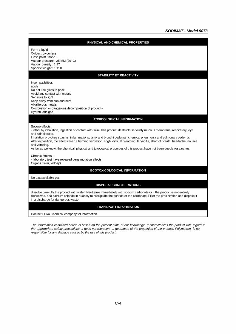
SODIMAT - Model 9073
C-4
PHYSICAL AND CHEMICAL PROPERTIES
Form : liquidColour : colourlessFlash point : noneVapour pressure : 25 MM (20EC)Vapour density : 1,27Specific weight : 1.150
STABILITY ET REACTIVITY
Incompatibilities :acidsDo not use glass to packAvoid any contact with metalsSensitive to lightKeep away from sun and heatAlkaliferous metalsCombustion or dangerous decomposition of products :Hydrofluoric gas
TOXICOLOGICAL INFORMATION
Severe effects :- lethal by inhalation, ingestion or contact with skin. This product destructs seriously mucous membrane, respiratory, eyeand skin tissues.Inhalation provokes spasms, inflammations, larnx and bronchi oedema , chemical pneumonia and pulmonary oedema.After exposition, the effects are : a burning sensation, cogh, difficult breathing, laryngitis, short of breath, headache, nauseaand vomiting.As far as we know, the chemical, physical and toxocogical properties of this product have not been deeply researches.
Chronic effects :- laboratory test have revealed gene mutation effects.Organs : liver, kidneys
ECOTOXICOLOGICAL INFORMATION
No data available yet.
DISPOSAL CONSIDERATIONS
dissolve carefully the product with water. Neutralize immediately with sodium carbonate or if the product is not entirelydisssolved, add calcium chloride in quantity to precipitate the fluoride or the carbonate. Filter the precipitation and dispose itin a discharge for dangerous waste.
TRANSPORT INFORMATION
Contact Fluka Chemical company for information.
The information contained herein is based on the present state of our knowledge. It characterizes the product with regard tothe appropriate safety precautions. It does not represent a guarantee of the properties of the product. Polymetron is notresponsible for any damage caused by the use of this product.

SODIMAT - Model 9073
C-5
C.3 AMMONIA SOLUTION (about 35% NH )3
PHYSICAL PROPERTY
SPECIFIC GRAVITY 0.88
SOLUBILITY IN WATER Miscible
VAPOUR PRESSURE 330 mm Hg at 0BC
VAPOUR DENSITY (air = 1) 0.6
pungent odour
FIRE AND EXPLOSION HAZARD Not applicable
HEALTH HAZARDS
Classification of risk-corrosiveIrritating to eyesIrrritating to respiratory systemIrritating to skinCauses severe burnsCauses severe internal damage if swallowedminimum lethal dose (LD50) = 350mg/kg oral rat.Occupational exposure standard, long term exposure limit(8hour TWA) 18mg m (25ppm).-3
Keep out of reach of children.
SAFETY PRECAUTIONS - FIRST AID
EYES In case of contact with eyes rinse immediately with plentyof water and obtain medical attention.
LUNGS Remove from exposure, rest and keep warm. In severecases, or if exposure has been great obtain medicalattention.
MOUTH Wash out mouth thoroughly with water and give plenty ofwater to drink. Obtain medical attention.
SKIN Drench the skin thoroughly with water and give plenty ofwater to drink. Obtain medical attention.

SODIMAT - Model 9073
C-6
CHEMICAL HAZARD AND STABILITY
Avoid contact with acids and oxidising agents.May react violently with oxygen and oxidising reagents.Reacts violently with boron halides and mercury. Reactsviolently or produces explosive materials with halogens andtheir compounds.
PROTECTIVE MEASURES
RESPIRATOR Self contained breathing apparatus.
GLOVES Rubber or plastic
EYE PROTECTION Goggles or face shield.
If handling large quantities use plastic apron, sleeves andboots.Use a fume cupboard.
SPILLAGE HANDLING
WARNING
Wear appropriate clothing. Evacuate area as necessary.
If local regulations permit, mop up with plenty of water andrun to waste, diluting greatly with running water. Otherwisetransfer to container and arrange removal by disposalcompany. Wash site of spillage thoroughly with detergentand water.
For large spillages liquids should be contained with sand orearth and both liquids and solids transferred to salvagecontainers. Any residues should be treated as for smallspillages.
If material has entered surface drains it may be necessaryto inform Local Authorities, including fire services ifflammable.
STORAGE AND HANDLING REQUIREMENTS
Store in a cool place, cool containers before opening. It isadvisable to place a cloth over the closure beforeattempting to open the bottle. UK labelling requirementsinclude those for schedule 2 poisons under the Pharmacyand Poisons Act 1933.
The information on this sheet is believed to be correct at the time of collation. The details should be reviewed periodically andshould be checked for special uses.
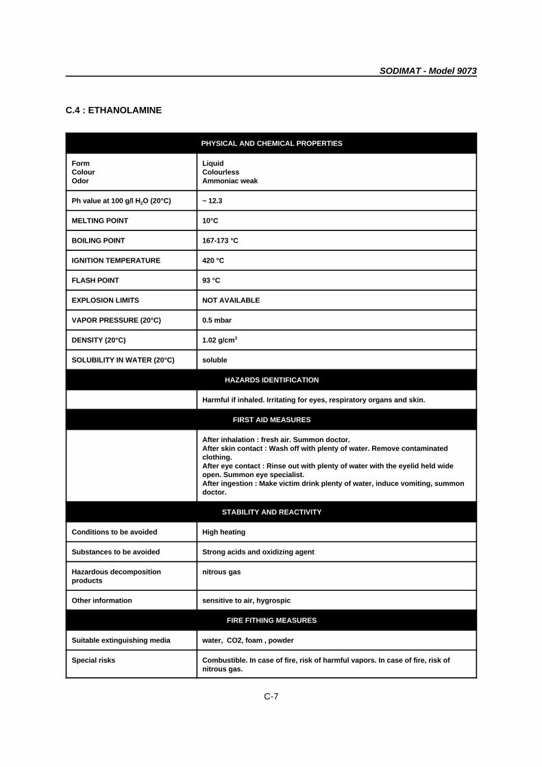
SODIMAT - Model 9073
C-7
C.4 : ETHANOLAMINE
PHYSICAL AND CHEMICAL PROPERTIES
Form LiquidColour ColourlessOdor Ammoniac weak
Ph value at 100 g/l H O (20°C) ~ 12.32
MELTING POINT 10°C
BOILING POINT 167-173 °C
IGNITION TEMPERATURE 420 °C
FLASH POINT 93 °C
EXPLOSION LIMITS NOT AVAILABLE
VAPOR PRESSURE (20°C) 0.5 mbar
DENSITY (20°C) 1.02 g/cm3
SOLUBILITY IN WATER (20°C) soluble
HAZARDS IDENTIFICATION
Harmful if inhaled. Irritating for eyes, respiratory organs and skin.
FIRST AID MEASURES
After inhalation : fresh air. Summon doctor.After skin contact : Wash off with plenty of water. Remove contaminatedclothing. After eye contact : Rinse out with plenty of water with the eyelid held wideopen. Summon eye specialist.After ingestion : Make victim drink plenty of water, induce vomiting, summondoctor.
STABILITY AND REACTIVITY
Conditions to be avoided High heating
Substances to be avoided Strong acids and oxidizing agent
Hazardous decomposition nitrous gasproducts
Other information sensitive to air, hygrospic
FIRE FITHING MEASURES
Suitable extinguishing media water, CO2, foam , powder
Special risks Combustible. In case of fire, risk of harmful vapors. In case of fire, risk ofnitrous gas.
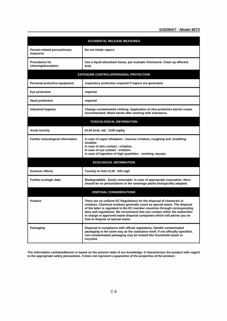
SODIMAT - Model 9073
C-8
ACCIDENTAL RELEASE MEASURES
Person-related precautionary Do not inhale vapors.measures
Procedures for Use a liquid absorbant tissue, par example Chemizorb. Clean up affectedcleaning/absorption area.
EXPOSURE CONTROLS/PERSONAL PROTECTION
Personal protective equipment respiratory protection required if vapors are generated.
Eye protection required
Hand protection required
Industrial hygiene Change contaminated clothing. Application of skin-protective barrier creamrecommended; Wash hands after working with substance.
TOXICOLOGICAL INFORMATION
Acute toxicity DL50 (oral, rat) : 2100 mg/kg
Further toxicological information in case of vapor inhalation : mucous irritation, coughing and .breathingtroublesIn case of skin contact : irritation. In case of eye contact : irritationin case of ingestion of high quantities : vomiting, nausea
ECOLOGICAL INFORMATION
Ecotoxic effects Toxicity on fish CL50 : 525 mg/l
Further ecologic data Biodegradable. Easily removable. In case of appropriate evacuation, thereshould be no perturbations in the sewerage plants biologicallly adapted.
DISPOSAL CONSIDERATIONS
Product There are no uniform EC Regulations for the disposal of chemicals orresidues. Chemical residues generally count as special waste. The disposalof the latter is regulated in the EC member countries through correspondinglaws and regulations. We recommend that you contact either the authoritiesin charge or approved waste disposal companies which will advise you onhow to dispose of special waste.
Packaging Disposal in compliance with official regulations. Handle contaminatedpackaging in the same way as the substance itself. If not officially specified,non-contaminated packaging may be treated like household waste orrecycled.
The information containedherein is based on the present state of our knowledge. It characterizes the product with regardto the appropriate safety precautions. It does not represent a guarantee of the properties of the product.