soaringdigest radio c ntrolled · 2019-08-12 · 2 r/c soaring digest 4 all about thermals chris...
TRANSCRIPT

SoaringDigestRadio C ntrolled
January 2018 Vol. 35, No. 1

2 R/C Soaring Digest
4 All About ThermalsChris Bryant, modeller and full size sailplane pilot, explains what thermals are, how they come about, and what makes them stop.
10 DFS Rhönbussard RevisitedHans-Jurgen Fischer provides additional drawings to supplement those in Elia Passerini's January 2017 treatise.
12 Advanced Snapflap Mixing with Lua Mike Shellim explains the various snapflap parameters and provides a suitable Lua script for OpenTX.
16 An Introduction to Calibration ModeCalibration Mode eases the process of calibrating your servos - centre, end points, etc. By Mike Shellim.
Corrections to "Flutter" 18By Chuck Anderson. Slope Soaring CandidateSukhoi Su-34 PSS 19RC Soaring Digest Global Reach 22RCSD readers are located around the world. Aerotow CandidateAkaflieg Munchen e.V. Mu 31 23Slopers in the mists 29Philip Randolph redefines having a good time on the slope in Part Deux and Part Tres of the continuing saga.
Front cover: Steve Kemp’s Emirates Airbus A380 seen flying at the Great Orme, North Wales, UK. This 72” span all moulded foam model is built from the Windrider PSS/EP kit and flies very well in medium slope lift. Photo by Phil Cooke, PSSA <http://www.pssaonline.co.uk>.Canon 7D & Canon 100-400L IS, ISO 160, 1/1250 sec., f5.6, 260 mm
January 2018Vol. 35, No. 1
CONT
ENTS
Back cover: The end of a good afternoon of soaring. Photo by Tony Beck. The models are Tony's 100" Kite published in RCSD last summer, and a home brewed 132" ship. Location is Charleston South Carolina. Samsung SM-G920V, ISO 64, 1/60 sec., f1.9, 28 mm equiv."Bremerton clouds" by Anna Holmes

January 2018 3
R/C Soaring DigestThe journal for RC soaring enthusiasts
January 2018Volume 35 Number 1
Managing Editors, Publishers Bill & Bunny (B2) KuhlmanContact [email protected]
http://www.rcsoaringdigest.comYahoo! group: RCSoaringDigest
FaceBook: https://www.facebook.com/RCSoaringDigest/
R/C Soaring Digest (RCSD) is a reader-written monthly publication for the R/C sailplane enthusiast and has been published since January 1984. It is dedicated to sharing technical and educational information. All material contributed must be original and not infringe upon the copyrights of others. It is the policy of RCSD to provide accurate information. Please let us know of any error that significantly affects the meaning of a story. Because we encourage new ideas, the content of each article is the opinion of the author and may not necessarily reflect those of RCSD. We encourage anyone who wishes to obtain additional information
to contact the author.
———
Copyright © 2018 R/C Soaring DigestPublished by B2Streamlines
http://www.b2streamlines.comP.O. Box 975, Olalla WA 98359
All rights reserved
———
RC Soaring Digest is published using Adobe InDesign CS6
In the AirThis edition marks the beginning of the 35th year of publication for RC Soaring Digest. Since its start in January of 1984 under Jim Gray, RCSD has been recognized as "the journal for RC soaring enthusiasts." Since taking over the roles of Managing Editors and Publishers it has been our endeavor to continue that legacy, and it is our sincere hope we have fulfilled that goal. Originally a printed publication, RCSD moved to the PDF format and electronic distribution in 2004 while Judy and Jerry Slates served as editors. Over a relatively short period of time all of the prior printed issues were scanned, converted to PDF, and made available at no charge through the Archives section of the web site. At the same time as the conversion of the magazine to PDF, subscriptions were discontinued and anyone who cared to read RCSD and had an internet connection could do so at no charge, regardless of where they were living. These simultaneous moves had the immediate effect of tremendously expanding readership, as those with only a minor interest or curiosity about RC soaring now had free access to an internationally recognized information source which catered to both novice and expert as well as everyone between those two extremes. To get an idea of the current RCSD global reach, we encourage you to take a look at the similarly titled page in this issue. RCSD would not be able to continue without those readers who choose to contribute the submissions and finances necessary. Our sincere thanks to you all! Time to build another sailplane!

4 R/C Soaring Digest
Thermals are free and renewable energy which we modellers rely on to further our flights. But what are they? Let ex-glider pilot and lifelong modeller Chris Bryant give you the benefit of his thirty-year experience actually flying in them.
What follows is based on my experience as a glider pilot and as a modeller in the UK. If you want to soar well then you have to visualise what is happening to the air around you if you are to exploit its opportunities successfully. I thought it necessary to deal with the subject as a whole but there should be plenty to glean for those who only fly modelsize.THE ATMOSPHEREFirst, a concept. Wind: think of it as an all-enveloping layer of gas flowing over the surface of our planet from high pressure to low. On the way it bumps over the surface of the earth and the lowest part, the troposphere (the stirred layer), is stirred up by things like land, sea and heat. If the air flowing over one area (like a warm sea) gets heated up more than that flowing over another area (an ice shelf), then the colder, heavier parts of the gas will try to burrow under the warmer, lighter parts. That makes weather fronts. That is part of the bigger picture. At flying field scale, the same thing may be going on but reduced in size and this imposes a further local dynamic over the bigger picture. If the temperature difference between warm and cooler bits of air is sufficient then cold will push up warm and you have the makings of a thermal. The indispensible
force needed to do this is gravity. The other component is, of course, sunshine. The necessary dynamic is differential heating. Where there is change of colour and texture in the surface then the sun will heat each differently. In turn the air passing over these disparate areas receives differing amounts of energy, the densities of the air streams change and the chances of thermal production increase. But it is not a guarantee that you will get thermals. Conditions have to be right. The air mass itself has to possess a certain latent energy – entropy. If that is wanting then nothing happens. More often than not this is called winter!The defining properties of entropy are temperature, pressure and humidity. When these are right you can have thermals and, if a thermal goes high enough, it can become a cloud.A long time ago I witnessed an experiment to try and define the motion of the troposphere. It consisted of a large loudspeaker lying on its back and an amplifier that fired bursts of sound into the sky. Alongside were microphones and a tape recorder to capture the echo sent back by the atmosphere passing overhead. Every fifteen minutes there was an almighty instantaneous bark from the speaker. The recording went on for several days 24/7; we did not get much sleep! The resulting tape was analysed in such a way that it revealed the size and rough shape of any distinct parcels of air above the speaker up to a height of a few hundred feet. A sort of air sonar. The results were surprising: the sample revealed discrete blobs of air ranging in size from a few inches to many feet across and that the arrangements of these blobs was random. The troposphere
All about thermalSChris Bryant, [email protected]

January 2018 5
above Lasham in Hampshire UK was living up to its name. It was stirred and quite chaotic.HOW TO MAKE A THERMALNow bring on your average soaring day and the sun comes up and starts heating up the landscape. For any given day the conditions will be unique and the air mass will either make thermals or not.Let us suppose that today is a cracker. It’s summer and, if you were up at dawn, there was mist covering the ground and no wind to speak of. The mist tells us that there is an inversion just above ground level. An inversion occurs when the temperature of the air stays constant or starts to rise with height instead of dropping. This can wipe out a thermal’s temperature difference compared to the surrounding air. It can stop upward progress. However, as the day progresses the wind picks up and the sun disperses the mist. The sun climbs in the sky and heats up the landscape a lot more. At a certain point, the conditions will be right and the little parcels of warmer air near the surface will start to coalesce until they form a parcel big enough and warm enough to lift through the inversion (which has risen to a hundred feet or more), detach from the earth and be forced up by the cooler parcels burrowing underneath it. [ Illustrations 1 and 2 ] Down low, in the first few hundred feet of its journey, the thermal will be weak, ill defined and small in diameter. As it climbs, it will tend to form a rolling torus rather like the ring clouds surrounding nuclear bomb plumes. As it rises it elongates vertically and may be followed by other puffs of warm air from the same source which may combine to form a column. Think of it as a deep doughnut shape where the
Illustration 1
Illustration 2

6 R/C Soaring Digest
bottom is constantly rolling into the centre and up and the top is expanding out and down. Low down the torus is quite small. The turning circle of a full-size glider might be 300 feet in radius and somewhat larger than the torus. The pilot may only find weak lift around the edge of the torus and what there is may be fragmented - strong in one part of the circle and not in another. The pilot must make a tight circle well centred on the torus to stay in any lift. A model, however, has a much smaller turning circle and you are better off when exploiting such a situation. [ Illustration 3 ] As the thermal rises so the torus becomes a column, gets more vigorous and spreads out until it reaches its condensation height – cloudbase – where the water vapour in it condenses out as cloud. Often this coincides with another inversion and the cloud spreads out above it, the thermal spills over like the top of a fountain and stops climbing. There may be other, weaker inversions that our thermal encounters on the way to becoming a cloud and these can deflect or even divert the thermal from its upward path. If any of these are strong enough they may prevent it from reaching condensation height and you get a blue day. Thermals but no clouds. Commonly, the lift on blue days is narrower, rougher and, of course, more difficult to find since there are no aerial clues to its whereabouts (unless you wear orange sunglasses which can make the rising currents just about visible).As the air in the torus rises, so cooler, denser air rushes in underneath it to fill the space it leaves. Thus thermals are often surrounded by sinking air. Also, it is inevitable that thermals will mix and blend with their surroundings and become polluted by cooler air. Nevertheless, to an extent they are self perpetuating since the rate at which the slightly wetter air in them cools can be about half that of
Illustration 3
the drier air surrounding them, maintaining or increasing the differential as they rise. Despite mingling with its surroundings, a thermal can arrive at cloudbase with sufficient power to carry on above condensation level and form a growing cloud. At this point the latent heat of condensation released by the clouds formation can boost the thermal up to stratospheric levels and a cumulo-nimbus can be created which has the potential to go bang and rain like hell. The lift under thunderheads that I have flown in can be a mile wide and very gentle. Go on up into the cloud and the rate of climb can double or more. Go above the freezing level and all hell breaks loose with hail, icing and extreme turbulence to contend with while you are flying blind!. Even on a hot day it is freezing above your head if you go high enough!

January 2018 7
[ Illustration 4 ] But this is not the whole picture. Two more factors influence the growth of the thermal: wind direction and strength usually change with height. Whilst our torus (perhaps the idea of a banana shaped parcel of air might be more appropriate in reality) is ascending the airmass it passes through is moving over the ground. [ Illustration 5 ] Thus thermals may swerve as they rise according to the strength and direction of the wind at various heights. Indeed,
if there is a sharp enough change of direction and strength with height (known as wind shear), the torus may get displaced laterally, may even shear off and reform at some distance from the lower column. The moral of this story is if the lift suddenly stops then make a wider circle and look upwind. It is as if the torus has capsized and you have fallen out the bottom of the last puff. Finally, thermals twist about their centres as they go up. In the Northern hemisphere they twist
clockwise; in the Southern hemisphere the twist is anticlockwise. This is due to the geostrophic wind force which affects the movement of the atmospheres of gassy planets throughout the universe. For modelling purposes you can ignore it. If you want to see it, fill a sink with water, pull the plug and watch the way the water goes down the plug hole. It twists - just as it would on Jupiter.
Illustration 4 Illustration 5

8 R/C Soaring Digest
WHAT STOPS THERMALS?Inversions.The wet Whilst some water content is necessary to provide entropy, too much is fatal. Keep away from wet areas on your flying field. Clouds [ Illustration 6 ] Equally, a lack of sunshine is obviously going to spoil your day. One of the great thermal killers is cloud shadow that falls on the ground source of the thermal you are in, killing it stone dead. Any cloud will do, not just the one you think you are thermalling under. For the same reason spreadouts at cloudbase may shut down thermal production for an hour or even the rest of the day if the inversion at cloudbase is strong enough and the updrafts are wet enough. You get spreadout and soon everywhere is in shadow. Every time a hole appears in the upper cloud strata it is filled by cloud from an ascending thermal. Alternatively, this phenomenon may only occur at one time of day when the sun’s angle to the earth’s surface makes the shadows and the sources of thermals coincide. When the sun or the clouds are either higher or lower it may not happen. So time of day is important.
Illustration 6

January 2018 9
Strong winds kill thermals. It can tear them to pieces, especially if the wind gradient near the ground is steep enough. A few miles per hour at ground level may become 20 or 30 miles an hour at one hundred feet. Such rapid change can be sufficient to roll thermals up and shatter them. A tip: sometimes it is wise to extend the into-wind leg of your circles to keep up with the lift production on the ground, especially when low. Keep moving the centre forward in the wind so that it remains more or less stationary with reference to the ground.Sunshine Then there is light. The strength of thermals is directly related, amongst other things, to the amount of heating the sun provides which is inextricably linked to its height in the sky. Is where you fly running under Greenwich Mean Time or is it an hour or two off it for local reasons? The sun’s heating peaks at midday GMT. Work it out.Lastly, a change of airmass can kill all lift. If wet sea air comes in in then forget it. Read your weather forecast. Where is the air mass coming from?WHERE TO FIND LIFT(Albedo) Contrast in the landscape is the generator of thermal lift. Astronomers call it albedo - the ability of a body’s surface to reflect back sunlight. Dark
buildings next to a grass field can be a source. Dark roads and runways are very effective. Hedgerows and woods can fill with warm air and not be good during the day but, as the sun goes down, they may release their heat when all other sources have died off. Fire is an obvious winner. Years ago, farmers in the UK used to burn off the stubble left after the wheat harvest had been brought in and I have completed cross country’s by flying only in the narrow and violent thermals stubble fires produce. Otherwise, the air was dead. It needed fire to reach the popping temperature. A very exciting ride I can tell you with bits of burning straw floating by, some of it coming in through the cockpit ventilators!Hills are good sources of thermal lift where there are sun-facing surfaces. The increase in wind speed that a hill may cause can help to strip warm air off the surface, even off the downwind side of a ridge if it is sunsoaked. The air may be sucked up the back surface and stripped off the top by wind shear. Even small clumps of vegetation, a hedge or thicket, may provide shelter from the wind and a suntrap that puffs off lift from time to time.You are very unlikely to hit a thermal head on. More likely, one wing of your model goes up and the usual rule is turn
towards the rising wing. On the other hand, if you get into sinking air without any roll then look upwind. If the sink gets stronger as you go on then that is often a sign you are heading towards your next source of lift. If it isn’t, start walking!Look at the clouds above where you are flying. Try to work out which cloud is at the top of the thermals you find. If it has a flat base and looks a firm, crisp, growing shape then it is working all the way to and above cloudbase. If it has no clear base and looks like a bad haircut then it is most likely dead and will be sitting on a pile of sinking air.Watch the grass and vegetation nearby for signs of movement. If the grass gets blown back the opposite way to the wind direction, you know something is happening. Either it’s the cold outflow from a collapsing thermal or the inflow to a new one just being borne. How long is it since the last thermal went off? That’s a clue.Chasing nature’s miracles is a fascinating sport. You are always learning something new.Be aware of the air!

10 R/C Soaring Digest
DFS Rhönbussard Revisited
The January 2017 edition of RC Soaring Digest featured Elia Passerini’s DFS Rhönbussard build and included what was noted as a 2-view drawing of the aircraft. We received an email from Hans-Jürgen Fisher, creator of the drawing, letting us know the illustration as presented was only a portion of the original and he was pleased to be able to provide a copy of the original for publication in RCSD. The original 3-view with cross-sections and other details, is shown at right. Hans-Jürgen also forwarded two additional drawings. The illustration below shows the DFS Rhönbussard on display at the Deutsches Segelflugzeugmuseum, Wasserkuppe, Germany. The illustration on the opposite page details the DFS Rhönbussard fuselage dimensions and materials. Our sincere thanks to Hans-Jürgen Fisher for providing these illustrations in their entirety for publication in RC Soaring Digest.

January 2018 11


January 2018 13
Snapflap (elevator-to-flap) mixing is a key mix for the F3F, F3B and F5B sailplane classes. Its purpose is to minimise drag during high-G turns, and it effects this by increasing the airfoil camber as the elevator stick is pulled. All high end RC systems incorporate a snapflap mix in their glider programs, however they tend to have limited in-flight adjustability. Often you’re restricted to altering volume – if you want to adjust other aspects of the curve such as expo, or deadband, then you may well have to land the model first. This makes it virtually impossible to optimise these parameters effectively. I therefore decided to make a custom snapflap mix which would allow me to vary all aspects of the snapflap mix in real time.In this article, I’ll describe how the enhanced mix is implemented in OpenTx. If you don’t have OpenTx, you may still be interested in the various considerations relating to the design of this mix. And who knows, you may be tempted to look into the dark side!The title page photo shows a “bank and yank” F3F turn during an F3F winter league event. Shot at 6 fps.The snapflap curveAt the core of any snapflap mix is a curve relating elevator stick movement to camber. The curve may be defined using four parameters: • Deadband - elevator stick deflection at which snapflap starts. • Volume – maximum snapflap deflection • Saturation limit - elevator stick deflection at which max snapflap is reached. • Expo – snapflap expoI wanted all four parameters to be independently adjustable. This meant that each parameter had to be linked to a dedicated transmitter control. This was easy enough with volume and expo. However, in common with other systems, OpenTx does not allow individual
curve points to be externally controlled, and this creates a problem for deadband and saturation limit. Fortunately, unlike most other systems OpenTx can call on Lua for help! Lua is a lightweight scripting language which is supported by OpenTx via a built-in interpreter. Scripts can be written to create highly customised mixers. ImplementationThe advanced snapflap mix makes use of a Lua script to pre-process the elevator input. The script takes two parameters P1 and P2 corresponding to deadband and saturation limit. These are used to construct a simple ‘S’ curve using 3 straight line segments. The curve is applied to the elevator stick value and the result is sent to a mixer where volume and expo are applied. Crucially, the values for deadband and saturation limit can be supplied by dedicated controls, just as with the other two parameters. So voila, all the curve parameters are now independently adjustable!
Graphic explanation of the four snapflap parameters.

14 R/C Soaring Digest
User interfaceWith four parameters to adjust, careful consideration must be given to the user interface. I’ve found the following works well on my Taranis X9D: • Volume - adjusted via the throttle trim. • Saturation limit - adjusted via a rotary knob. • Expo - adjusted via the right slider. • Deadband – currently, I preset this value via a menu, as I didn’t think this was a critical adjustment. In hindsight, it should be directly adjustable like the other parameters. It’s a simple mod to the Lua script.Ease of maintenanceF3X models are complex, but that doesn’t mean that the programs should be difficult to adjust or maintain. Quite the opposite - if due consideration is given at the design stage. Here again OpenTx comes up trumps through its support of hierarchical channel structures. This means that all four wing servos can be served by a single snapflap mix, so all the complex stuff is in one place – no duplication of Lua code or mixes required. This makes changes very easy to manage. To ensure precise tracking of flaps and ailerons, regardless of mechanical differences, all my setups incorporate a custom servo calibration mode.
Audio alertsWhen trimming out the advanced snapflap mix, it’s important for the pilot to be aware of the state of the mix. I have therefore configured some audio alerts, in the form of short beeps. These are triggered when (a) snapflap kicks in, and (b) snapflap reaches the maximum. The alerts have proved useful for adjusting deadband and saturation limit.

January 2018 15
Sample snapflap curvesAbove are sample curves which can be generated by the system (the data was recorded using a second script). Adjusting the curve After several sessions of tweaking and exploring, I’ve settled on the following method of tuning the advanced snapflap mix: • Volume – start with the snapflap travel as recommended by the manufacturer, adjust as necessary. • Expo – initialise to zero (linear), then tune as necessary for smooth turns with minimal energy loss. • Deadband – start off at zero, and increase just enough to suppress unwanted snapflap deflections due to minor pitch corrections on the straight. Audio alerts are helpful for this adjustment
• Saturation limit - adjust this to achieve max camber when pulling a tight/fast turn, while preventing over-cambering when pulling too hard (easy to do when turning late during an F3F run). An audio alert at max snapflap is useful here.SummaryThe enhanced snapflap system has achieved my goal, which was to facilitate the tuning of the snapflap mix. It’s now an indispensable part of my F3F programming armoury. OpenTx is not the only system to offer Lua - Jeti also provide a built-in Lua interpreter and it may be possible to duplicate my system on those transmitters. However, I have insufficient knowledge of Jeti systems to comment in detail. Safe flying!

16 R/C Soaring Digest
Links: Enhanced snapflap script: <http://rc-soar.com/opentx/lua/snp302.txt>OpenTx Clinic: <http://www.rc-soar.com/opentx/> Snapflap thread on RC Groups (with contributions from Mark Drela and Joe Wurts):<https://www.rcgroups.com/forums/showthread.php?696969-Snap-Flap-How-much-and-why>Programming OpenTx - getting to grips with Lua: <http://rc-soar.blogspot.co.uk/2014/07/getting-up-to-speed-with-lua.html>
Calibration Mode is a special flight mode which you can add to any model. It eases the process of calibrating your servos. Calibration mode can also facilitate the precise matching of paired surfaces like flaps and ailerons. When Calibration Mode is active, all mixers and trims are disabled, allowing absolute end points and centres to be visualised directly.
ExampleCAL mode is implemented via a ‘REPLACE’ mix at the end of each servo channel. Here’s an example applied to Channel 1:
An Introduction to Calibration Mode
Mike Shellim, [email protected]
http://rc-soar.com/opentx/setups/calmode/calmode.htm

January 2018 17
When the CAL mix is active, all the mixes above are ignored (because of the REPLACE directive). The elevator value is passed directly to the Outputs layer, where it’s scaled according to the values of Min/Max/Subtrim. This results in the following behaviour: • Ele stick at end points => Servo at absolute limits (Min, Max) • Ele stick at neutral => Servo at centre (Subtrim)In practice, the channel numbers and mix parameters will depend on your model, and how you want CAL mode to operate. How to integrate Calibration Mode in your setup This section explains how to implement CAL mode in more detail. Step 1 - create CAL mixes For each of the servo channels, append a mixer-line as follows: • Source = [stick used for calibration, see below ] • Weight = -100 or +100 (see below) • Offset = 0 • Diff = 0 • Include Trim = No (bypass trims) • Include DR/Expo = No (bypass rates) • Flight mode = FM1 (optional, see below) • Multiplex = ‘REPL’ (replaces all prior mixer lines above for that channel) Src is the stick or 3-pos switch to set the end points and centre. You can choose any convenient control - it need not be the same as the control used in flight. If using an analog control (stick, lever, or pot) make sure to specify the raw stick for example Ele, Ail (inputs for example [I1]Ail should not be used as they may include rates and expo).Use a single control to calibrate a pair of related surfaces. Here’s a typical scheme for a sailplane: • Aileron stick -> calibrate left/right aileron servos • Throttle stick -> calibrate left/right flap servos
• Elevator stick -> calibrate elevator servo (X-tail) or left/right V-tail servos (V-tail) • Rudder stick -> calibrate rudder servo (X-tail only) Step 2 - activate using a switch The CAL lines may be activated directly via a switch, or indirectly via a dedicated flight mode. The flight mode method has the advantage that the flight mode is displayed on the screen, but requires that you use FM1 (the highest priority mode). If this is inconvenient (maybe you already have flight modes assigned), then the direct switch approach is fine. Whichever method you choose, I strongly recommend using a virtual switch - the last thing you want is to accidentally activate calibration mode in flight! Step 3. Set servo rotation and mixer weights To make the calibration procedure as intuitive as possible, set the DIRECTION of each servo so that: • A +ve change in MIN, MAX or SUBTRIM moves the control surface up or to the right. • A -ve change in MIN, MAX, or SUBTRIM moves the surface down or to the left. The easiest way is to try it and see: go into the servos menu; for each servo, adjust SUBTRIM back and forth, and see which way the control surface is moving. If you reverse the direction of a channel, remember that effect of any mix will be reversed. To correct this, reverse the sign of the wt parameter of all the mixers affecting that channel. If you’ve set the direction of rotation as suggested above, then the weights in the CAL mixes should all be set to +100. This will ensure that all surfaces will move in a consistent direction during calibration - this is particularly useful for surfaces, like ailerons and flaps, which have been paired up for calibration.

18 R/C Soaring Digest
Demo
For OpenTx 2.0, 2.1, 2.2 calmode.zip http://rc-soar.com/opentx/setups/calmode/calmode.zip SF-down to activate CAL mode
Stick calibration For correct operation of your radio, remember that your sticks must also be properly calibrated as well! This is achieved via the OpenTx hardware calibration menu (Long press Menu -> Page x 8).
Screenshot Below is a screenshot from OpenTx Companion, showing two aileron channels and the extra CAL lines. The ‘R’ at the beginning denotes a REPL directive.
I started writing the flutter article several years ago after finding Skip’s article, but it took several years for the article to jell. Somewhere along the way, I substituted Mark for Skip and never caught the error. I am very bad at proof reading my own writing because I tend to read what I intended to write instead of what is on the paper/screen. “Field mod” was a bad choice of words. I should have said “modified while flying at the Denver F3B team selections contest.” Modelers automatically think field mod means made at the model field, not made in service. To me, field mod means changes made to a plane in service without returning to a contractor. I suppose it comes from my over 40 years in the Air Force and working for an Air Force contractor.
Skip wrote a long article about his modifications where he described his quick modification to one wing and the test flights he made to verify that the mod would reduce the flutter before he modified the other wing. The Miller Mod reduced the camber of the E387 airfoil and actually improved the performance so the modified airfoil was used on the Aquila Grande. Skip posted a shorter version of the article on RC Groups and can be found at <https://www.rcgroups.com/forums/showthread.php?817229-Aquila-Skip-Miller-mod>. It would be interesting to compare the actual model Skip flew at Denver to the one he used in South Africa to become the first F3B World Champion.
Corrections to “Flutter,” RCSD-2017-12, pp. 37-40 Chuck Anderson, [email protected]

January 2018 19
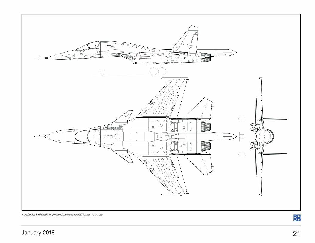
The Sukhoi Su-34 is a twin-engine, two seat, all-weather fighter/bomber/strike aircraft with medium range and supersonic (Mach 1.8+) capability. In operation since 2014, NATO has given this aircraft the designation Fullback. The Su-34 design is based on the Sukhoi Su-27 Flanker, sharing most of its wing structure, tail, and engine nacelles with that aircraft. Additionally, canard surfaces have been added which are much like those used on the Su-27M and Su-33. The canards improve maneuverability and reduce trim drag. The Su-34 is thus a three-surface design with foreplane, main wing, and conventional tailplane. The twin vertical surfaces are similar to those of the Su-27.The Su-34 has an armored cockpit, and seating is side-by-side. Crew comfort was a major consideration in the cockpit configuration. This has resulted in a rather spacious flight deck, with room for crew members to stand and move around during longer missions. There is space between the seats alrge enough for aone of the crew to lie down in the corridor. A galley and toilet are located behind the seats. The wide fuselage and low-slung nose contributed to the aircraft nickname “Duckling” or “Duckbill.”
Slope Soaring Candidate
Sukhoi Su-34
https://upload.wikimedia.org/wikipedia/commons/2/24/Russian_Air_Force_Sukhoi_Su-34.jpg

20 R/C Soaring Digest
https://upload.wikimedia.org/wikipedia/commons/2/23/Sukhoi_Su-34_flight_display_at_2015_MAKS.jpg https://upload.wikimedia.org/wikipedia/commons/7/76/MAKS2015part1-10_%28cropped%29.jpg
https://upload.wikimedia.org/wikipedia/commons/d/d6/Russian_Air_Force_Sukhoi_Su-34_Beltyukov-1.jpg https://upload.wikimedia.org/wikipedia/commons/7/7f/Sukhoi_Su-34_at_the_MAKS-2013_%2803%29.jpg
January 2018 21
https://upload.wikimedia.org/wikipedia/commons/a/a5/Sukhoi_Su-34.svg

22 R/C Soaring Digest
United StatesUnited KingdomItalyGermanyFranceAustraliaCanadaSpainCzechiaPolandNetherlandsRussiaSwitzerlandBelgium New Zealand South Africa Austria Sweden Slovenia Argentina
Japan Slovakia BrazilSingapore Norway Portugal Denmark China Belarus Ukraine TaiwanPeru Finland Greece Hong Kong Lithuania Romania Colombia Bosnia & Herzegovina Chile
South Korea Mexico VenezuelaHungary Mayotte Costa RicaIrelandUnited Arab EmiratesBulgariaIndiaCroatiaIndonesiaThailandPhilippinesCyprusTurkeyUruguayJerseyIranIsrael
Puerto RicoEstoniaKazakhstanLuxembourgMalaysiaSaudi ArabiaArubaCambodiaLatviaReunionRwandaVanuatuKosovoAndorraBahamasAlgeriaEcuadorEgyptFaroe IslandsIraq
IcelandJamaicaKyrgyzstanKuwaitLebanonSri LankaMoroccoMauritiusNamibiaNicaraguaFrench PolynesiaPakistanPalauTongaTanzaniaUzbekistanBritish Virgin IslandsVietnam
RC Soaring DigestGlobal Reach
In an effort to improve the RC Soaring Digest web site, the main page was recently coded to send visitor data to Google Analytics. We thought we’d share the first 90 days of data collection relative to visitor location with readers as it shows the global reach of RCSD. This information should act as an impetus to those thinking about submitting materials for publication as it clearly illustrates the international scope which RCSD enjoys. The RCSD web site has had visitors from the following nations:

January 2018 23
A k a f l ie g
Aerotow candidate
München e. V. Mü 31

24 R/C Soaring Digest
The design idea of the Mü 31 is to achieve a minimization of the interference resistance between the fuselage and the wing. The interference resistance is the resistance that occurs when merging two flow bodies. Constructively, a negative interference resistance is sought, that is, the composite components hull and wings have a lower resistance than the sum of the individual resistances. At the end of the 1990's a concept was developed by students of the Akaflieg Munich on this detail at the TU-Delft and verified with several wind tunnel investigations and several simulations.
It started with measurements of three wind tunnel models of different configurations: 1. a planar wing in centerdeck configuration (conventional), 2. a high-deck arrangement and restriction to the fuselage-wing transition, 3. a high-wing arrangement with a restriction to the fuselage and additionally a turbulent profile in the intersection area between wing and fuselage. Here, the third configuration proved to be the best and so this became the basis for further investigations and a further development series, which was completed in 2006. The complete report is available in PDF format. Please see the Resources section at the end of this article for information.
Artist rendering of the Akaflieg München Mü 31.
Title page photo: The Akaflieg München Mu 31. Photo taken during maiden flight, September 15, 2017. Akalieg München <https://upload.wikimedia.org/wikipedia/commons/e/e4/M%C3%BC31_im_Flug.jpg>
January 2018 25
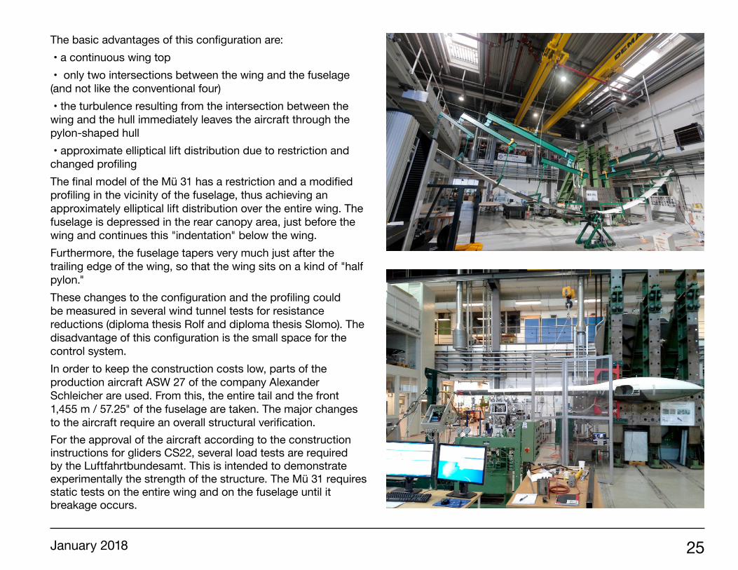
The basic advantages of this configuration are: • a continuous wing top • only two intersections between the wing and the fuselage (and not like the conventional four) • the turbulence resulting from the intersection between the wing and the hull immediately leaves the aircraft through the pylon-shaped hull • approximate elliptical lift distribution due to restriction and changed profiling The final model of the Mü 31 has a restriction and a modified profiling in the vicinity of the fuselage, thus achieving an approximately elliptical lift distribution over the entire wing. The fuselage is depressed in the rear canopy area, just before the wing and continues this "indentation" below the wing. Furthermore, the fuselage tapers very much just after the trailing edge of the wing, so that the wing sits on a kind of "half pylon." These changes to the configuration and the profiling could be measured in several wind tunnel tests for resistance reductions (diploma thesis Rolf and diploma thesis Slomo). The disadvantage of this configuration is the small space for the control system. In order to keep the construction costs low, parts of the production aircraft ASW 27 of the company Alexander Schleicher are used. From this, the entire tail and the front 1,455 m / 57.25" of the fuselage are taken. The major changes to the aircraft require an overall structural verification. For the approval of the aircraft according to the construction instructions for gliders CS22, several load tests are required by the Luftfahrtbundesamt. This is intended to demonstrate experimentally the strength of the structure. The Mü 31 requires static tests on the entire wing and on the fuselage until it breakage occurs.

26 R/C Soaring Digest
Before the break, tests were run to the safe load and the strains were measured and checked by means of strain gauges. Until then, no permanent deformation may occur. Both the wing and the fuselage have already gone through the break attempt. The breakage test for the wing corresponds to a 15 m/s / 50'/s gust from below at 218 km/h / 134 mph, with a load of 6.58 g. The load on the wing is about 15kN = 1.5 metric tons / 3300 lbs. Video at<https://www.youtube.com/watch?v=HwgxfXJohi0>The first flight of the Akaflieg München Mü 31 took place at Königsdorf Bavaria on September 15, 2017. The plans presented here are a 10x enlargement of plans available on the Akaflieg München web site and dimensions are not entirely legible. Those interested should contact Akaflieg München to inquire about the availability of more detailed drawings.
Resources: Akaflieg München has several web pages devoted to the Mü 31. The “index” page is at <http://www.akaflieg.vo.tu-muenchen.de/index.php/mue-31>. Akaflieg München is in the process of providing these pages in English. Google, Bing, and other translation services do a very good job at translating the present German language pages to English. Wikipedia has an entry for the Akaflieg München Mü 31, but the URL is very specific: <https://en.wikipedia.org/wiki/Akaflieg_M%C3%BCnchen_M%C3%BC31>.“Aerodynamic design of the wing-fuselage junction for the high-performance sailplane Mu-31” by Rolf Berger and Loek Boermans is available as a downloadable PDF from <http://journals.sfu.ca/ts/index.php/ts/article/view/233>.
Artist rendering of the Akaflieg München Mü 31. Note the indentation in the fuselage under the wing and the wing leading edge shape at the root.
Artist rendering of the Akaflieg München Mü 31. This image accentuates the fuselage depression under the wing and shows the rear of the half-pylon.

January 2018 27
Akaflieg München Mü 31 at the ILA Berlin Airshow, 2016. <https://en.wikipedia.org/wiki/File:Akaflieg_Munchen_Mu31.jpg>

28 R/C Soaring Digest
DIMENSIONS
Span 15 m Wing area 9 m² Aspect ratio 25 Winglet 0.45 m Empty weight 275 kg Maximum take-off mass 500 kg Maximum water ballast 150 l / 40 gals
150 kg / ~330 lbsTop speed 285 km/h Maneuvering speed 217 km/h Minimum speed 67 km/h Lowest sinking 0.5 m/s
Some of the students and staff responsible for the Akaflieg München Mü 31 gather around the fully assembled aircraft.

January 2018 29
Flying visible airflows Part Deux: Sam’s Dirty Ridge, November 5, 2017, Part Tres: Sam’s Dirty Ridge, November 17, 2017
CEWAMSSlopers in the mists
Philip Randolph, [email protected]

30 R/C Soaring Digest
Part Deux, November 5, 2017: 8.237 hours of driving just to fly in fog with freezing fingers? Ah well. Good trip! Except that the photographers (mostly me) mostly got Philip, and missed Sanders Chai and Steve Allmaras flying their 3+ meter planes, a Euphoria and a Graphite. Ah well. Interpolate. Headed east from Seattle, by about 8 AM we’re approaching Snoqualmie Pass and it’s snowing hard. For the next thirty miles it’s slow traffic and snowplows.
We’re headed for the east end of the Horse Heaven Hills. They are a geologic sheer, dropping steeply down to the Yakima River Valley to the NNW, but gently rolling wheat land to the south. We’re headed about 70 miles east of Yakima, where in 1912 Philip Parmalee, previously a Wright Exhibition Flyer, fatally crashed in Yakima’s typically turbulent summer winds. It’s raining hard. What are we in for?
2: Steve’s Evo without wingtips. Philip’s white Mini Ellipse, nearly invisible against the snow. Prodij and Mini Blade.
3: Steve and his Boomerang.
Title page: 1: The road up from Kiona. What are we getting into?
January 2018 31
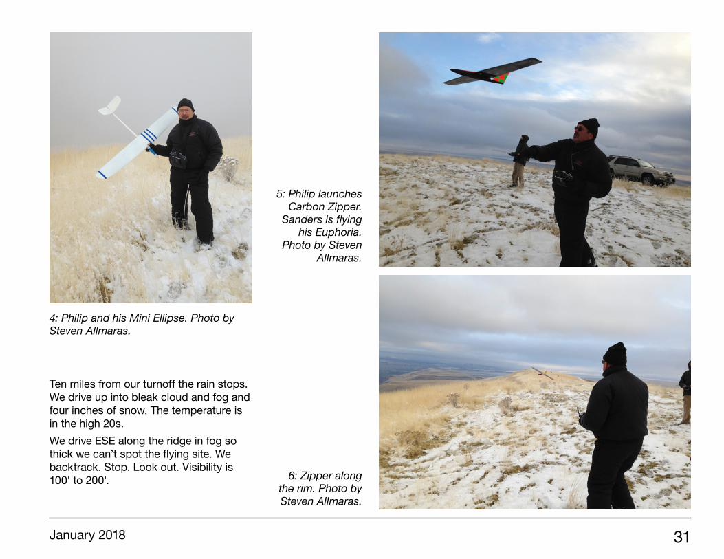
Ten miles from our turnoff the rain stops. We drive up into bleak cloud and fog and four inches of snow. The temperature is in the high 20s. We drive ESE along the ridge in fog so thick we can’t spot the flying site. We backtrack. Stop. Look out. Visibility is 100' to 200'.
4: Philip and his Mini Ellipse. Photo by Steven Allmaras.
5: Philip launches Carbon Zipper.
Sanders is flying his Euphoria.
Photo by Steven Allmaras.
6: Zipper along the rim. Photo by Steven Allmaras.

32 R/C Soaring Digest
910
11 12

January 2018 33
I climb into a snow suit, two jackets, a neck warmer and a cap, doubled light gloves with a couple fingertips cut off, and snowmobile boots. I have to some extent cheated. I have piled four 60" slopers into the back of Sanders’ rig, assembled, ready to fly. I pile them in the snow. It’s not quite whiteout conditions. But close. Which explains why Sanders and Steve chant, “Throw the white one.” That’s a Jaro Muller Mini-Ellipse. Note that in the plane pile pic (2) it disappears. It’s there. I disappoint them. I add blue electrical tape stripes. I haven’t flown either Mini-Ellipse or my Prodij before. Wind meter says 13 mph. I chuck the into the uniform oncoming fog. It is very well behaved, needing almost no trim adjustment. And
This page upper right (7) to opposite page upper left (10): 7: Philip Launches the Mini Ellipse into the fog. Photo by Steven Allmaras. 8: Mini Ellipse. Photo by Steven Allmaras. 9: Mini Ellipse, flying in close so I can see it. Photo by Steven Allmaras. 10: Mini Ellipse disappears sometimes. Photos by Steven Allmaras.
Opposite page lower: 11 & 12: 9: Steven and his Boomerang.
78

34 R/C Soaring Digest
with very limited visibility the Ellipse is the right plane. It is very agile. It whips around close in. Steve flies his Boomerang. His and Sanders’ bigger faster planes would disappear into cloud before they could turn. After an hour or so in which I ignore my icy fingers it slowly starts to clear up. Steve flies his Prodij. Flies great. Breaks an aileron horn on landing.
I fly my Prodij. Great flyer, but oddly wants its left aileron up 1/8" to fly straight. What? Maybe a twisted wing? (Since verified. I’ll de-twist it over the winter.) The sun comes out! Sanders puts his 3.6 meter Euphoria up. Steve launches a 3.1 meter Vladimir Models Graphite II. He hasn’t sloped it before, but trimmed it at a flat field. Flies sweet.
13: Philip with Mini Blade. Photo by Steven Allmaras. 14: Launching Mini Blade. Photo by Steven Allmaras.
15: Mini Blade: Photo by Steven Allmaras.

January 2018 35
15

36 R/C Soaring Digest
Philip was too busy flying to take pics. Bad Philip. This is a great LZ for crunchies. The grass is almost knee high, and no rocks. My fingers, well, they feel like I’m pushing the stick with little ice cubes, but I fly a lot. Steve has full gloves and still says, “It’s so cold I can’t fly for more than twenty minutes at a time.” I fly my 60" carbon wing Zipper and then the 60" Mini-Blade The Blade has a trap. It flies fast and smooth out front. On two trips while landing it has spiraled in. Three times on this trip. The third time the glue that holds its nose breaks free. Separates, rather than breaks. Only a plastic ball link loop breaks. Consistent. I wonder if it is prone to tip stalls. Pointy tips making trouble? This is the plane I got with its right wing’s leading D-cell puffed up like a sausage with expanding foam. I thought I got the airfoil fixed pretty well, but, is that the problem? There were two problems. It isn’t until I get it home that I figure what happened. The right wing servo is buried beneath shiny aluminum furnace tape. The epoxy holding it has broken free. That probably happened before I got it, during or before the damage to its right wing. The servo was then either kept in position by the tape’s adhesive or by the cutout in the lower hollow molded wing skin. And that was adequate for the gentle controls of high-speed flight. But the larger control inputs during an upwind slow landing pop the servo out of its nest. Spiral. Quickly fixed. Except that the manufacturer put the little X of tubes into which the V-tail rods slip so close to the back end of the fuselage that there is only room for the tiniest ball-end caps. And so many sites don’t list specs, other than to say, “This fits a DipsidoodleCopterThropter.” The result is that I bought three kinds of ball ends before I got some that worked.
On RC Groups I find that the Mini Blade does have tip-stall problems. A couple guys use reflex in landing mode, and recommend landing fast. Okay. I’ll also put a fair amount of differential in, and more for landing mode. That should stop a lowering aileron from stalling a wing. A long drive back to Seattle, with Sanders diligently at the wheel. We stop in Yakima at a small Mexican Restaurant, El Grullense. They serve an amazingly good pasole, hominy and pork soup. A huge bowl, and hot. Snoqualmie Pass is a zoo of semi trucks chaining up, lumbering, and unchaining.
16
16: Sanders’ Big Bird.

January 2018 37
Part Tres, November 17, 2017: Two weeks later we got out again. First about eight guys to Eagle Butte on the Friday after Turkey Day. 30 knot winds. Few pics, so skip that. Saturday seven of us got to Sam’s Dirty Ridge: Rick Jay, Tom Provo, Sanders Chai, Steve Allmaras, and me. Erik Utter and his son Cole (8) showed up in the afternoon. Temps around 40, 13 mph winds. Well, again, I flew so much that I didn’t take enough pictures.But I got a few.
17: Erik Utter’s Herring, flown by eight-year-old Cole, and Sanders’ Big Bird.
1817
19
19: Sanders’ Starlight 3000.
18: Sanders’ Big Bird looking east.

38 R/C Soaring Digest
20: Sanders’ Starlight 3000, Erik’s Herring 34".21: Steve’s Evo. 22: Erik Utter’s Herring and Evo.
23: Sanders’ Big Bird in back, Philip’s Prodij, Mini Ellipse and FrankenWiffleBatFuse 64 in the middle row, and Carbon Zipper
and Monarch II fuselage with DLG wing in the foreground.
2120
22

January 2018 39
23
