so, you want to know connectors
TRANSCRIPT
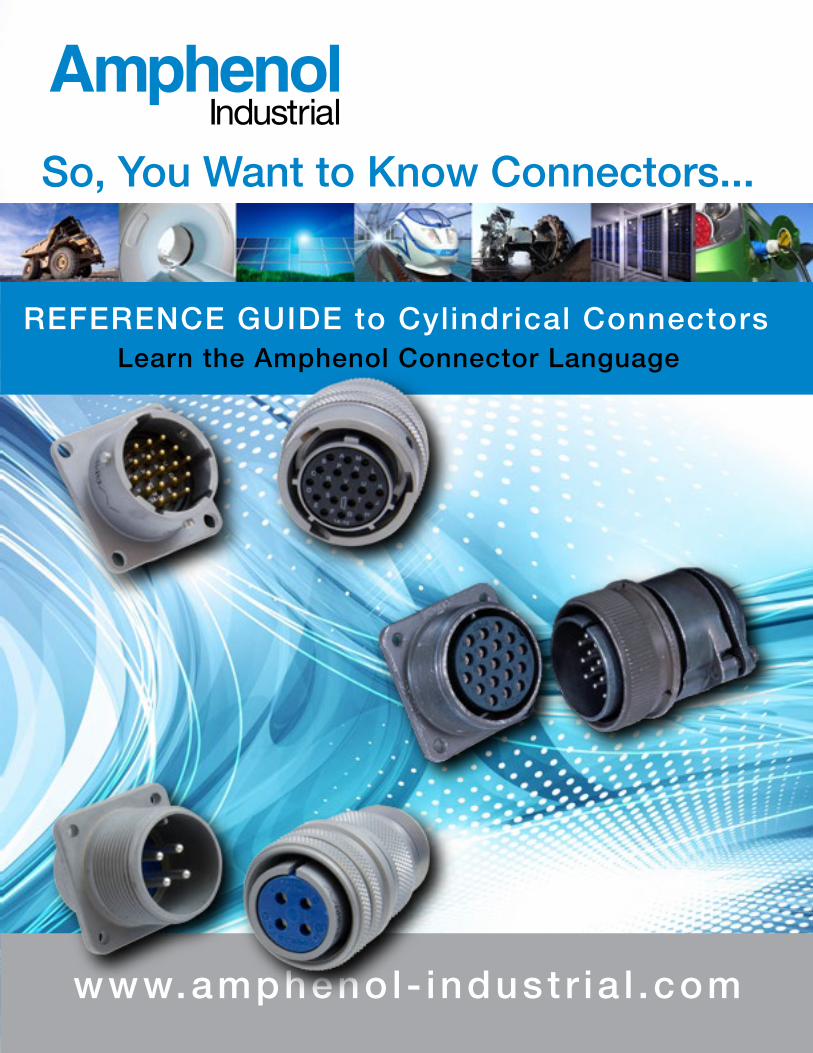
So, You Want to Know Connectors...
REFERENCE GUIDE to Cylindrical ConnectorsLearn the Amphenol Connector Language
www.ampheno l - indust r ia l .comNotice: Specifications are subject to change without notice. Contact your nearest Amphenol Corporation Sales Office for the latest specifications. All statements, information and data given herein are believed to be accurate and reliable but are presented without guarantee, warranty, or responsibility of any kind expressed or implied. Statements or suggestions concerning possible use of our products are made without representation or warranty that any such use is free of patent infringement and are not recommendations to infringe any patent. The user should not assume that all safety measures are indicated or that other measures may not be required. Specifications are typical and may not apply to all connectors.
IB-6-4
AMPHENOL CORPORATION Amphenol IndustrialPhone: 888-364-9011191 Delaware AvenueSidney, NY 13838-1395www.amphenol-industrial.com
3/22/2017
This booklet is intended to be used as a ready reference to typical standard, miniature and subminiature cylindrical connector part numbers and terminology. Reading its brief pages will not make you a connector expert, but should guide you in becoming familiar with the product, in order to better serve our customers.
Manufacturing connectors since 1932, we take pride that Amphenol Industrial Operations is the undisputed leader in interconnect systems for harsh environment applications. Such applications require a high degree of engineering sophistication and precision manufacturing capability. Innovations like our RADSOK® contact technology can provide roughly 50% more current through the same size pin. Connectors utilizing this RADSOK® technology will outperform similar products in the market hands down.
Amphenol Industrial Operations (AIO), a division of the Amphenol Corporation, is the leading manufacturer of cylindrical connectors in the world. Amphenol Industrial's product lines consist of rectangular, standard miniature, fiber optic, EMI/EMP filter, and a variety of special application connectors.
Headquartered in Sidney, NY, AIO’s facility is nestled at the foothills of the Catskill Mountains, and over 307,000 ft². This complex houses over 1,000 employees, incorporating state-of-the-art manufacturing technologies. The facility is both ISO9001 certified and qualified to MIL-STD-790 requirements. Other satellite manufacturing/assembly facilities are located in Nogales, Mexico (25,000 ft²) and Zhuhai, China with (276,000 ft²).
Our manufacturing capabilities include state-of-the-art CNC machining, die-casting, molding, impact and extruding, plating, screw machining and process controls.
AIO also has a fully equipped material evaluation lab and an engineering support organization utilizing the latest in computer aided design software and analysis tools.
Amphenol Industrial Operations is supported by several satellite plants and one of the largest distributor networks in the world.
For more information and for Amphenol catalogs onlinego to: www. amphenol-industrial.com.
Amphenol Industrial Products Group191 Delaware AvenueSidney, New York 13838-1395Phone: 888-364-9011Fax: 520-397-7169Email: [email protected]
ContentsSECTION INomenclature: Cylindrical Connectors .................................. 1-3 Basic Components
SECTION IIMajor MIL-Specifications by TypeStandard, SAE AS50151Amphenol AC Threaded SeriesAmphenol 97 SeriesProprietary Variations .............................................................. 4-6 SAE AS50151, AC and 97 Series Part Number Breakdown
SECTION IIIGT - Reverse BayonetACA-B Reverse BayonetProprietary Variations .............................................................. 7-8 GT and ACA-B Series Part Number Breakdown
SECTION IVMajor MIL-Specifications by TypeMiniature, MIL-DTL-26482.................................................... 9-12 MIL-DTL-26482 Part Number Breakdown Miniature Crimp, Solder Part Number Breakdown
SECTION VCross Reference by MIL-Spec to Competitor’sand Amphenol Part Numbers .................................................. 13 Intermating Chart
SECTION VIKnow the Language........................................................... 14-18Basic Questions to Determine Connector Requirements ....... 17What Do You Need to Sell............................. Inside Back Cover Checklist Conclusion Connector Sales Worksheet
NOTE: SAE AS50151 supersedes MIL-DTL-5015 MIL-DTL-26482 supersedes MIL-C-26482
1
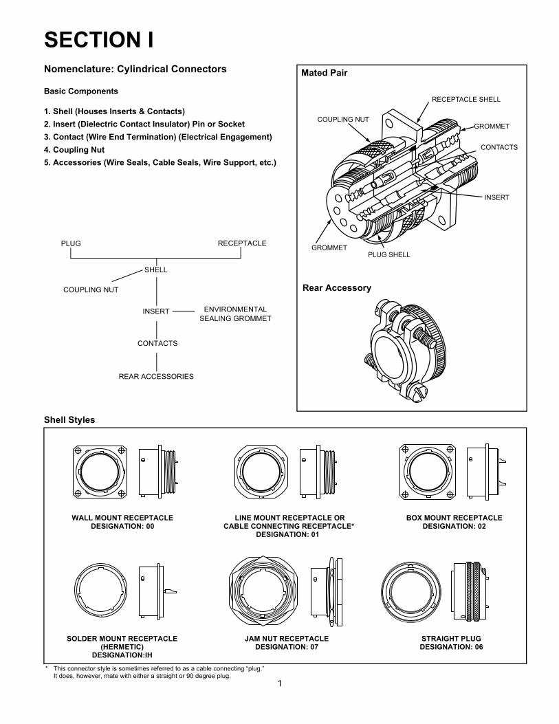
SECTION I
PLUG RECEPTACLE
SHELL
COUPLING NUT
INSERT ENVIRONMENTALSEALING GROMMET
CONTACTS
REAR ACCESSORIES
Shell Styles
WALL MOUNT RECEPTACLE LINE MOUNT RECEPTACLE OR BOX MOUNT RECEPTACLEDESIGNATION: 00 CABLE CONNECTING RECEPTACLE* DESIGNATION: 02
DESIGNATION: 01
SOLDER MOUNT RECEPTACLE JAM NUT RECEPTACLE STRAIGHT PLUG(HERMETIC) DESIGNATION: 07 DESIGNATION: 06
DESIGNATION:IH
* This connector style is sometimes referred to as a cable connecting “plug.”It does, however, mate with either a straight or 90 degree plug.
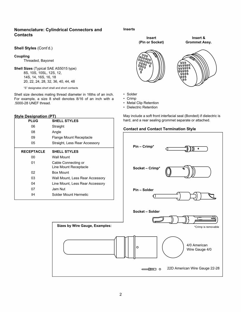
Nomenclature: Cylindrical Connectors
Basic Components
1. Shell (Houses Inserts & Contacts)2. Insert (Dielectric Contact Insulator) Pin or Socket3. Contact (Wire End Termination) (Electrical Engagement)4. Coupling Nut5. Accessories (Wire Seals, Cable Seals, Wire Support, etc.)
Mated Pair
Rear Accessory
COUPLING NUT
RECEPTACLE SHELL
GROMMET
CONTACTS
INSERT
PLUG SHELLGROMMET
2
Inserts
Insert Insert &(Pin or Socket) Grommet Assy.
• Solder• Crimp• Metal Clip Retention• Dielectric Retention
May include a soft front interfacial seal (Bonded) if dielectric is hard, and a rear sealing grommet separate or attached.
Nomenclature: Cylindrical Connectors andContacts
Shell Styles (Cont’d.)
CouplingThreaded, Bayonet
Shell Sizes (Typical SAE AS5015 type)8S, 10S, 10SL, 12S, 12,14S, 14, 16S, 16, 1820, 22, 24, 28, 32, 36, 40, 44, 48
“S” designates short shell and short contacts
Shell size denotes mating thread diameter in 16ths of an inch.For example, a size 8 shell denotes 8/16 of an inch with a.5000-28 UNEF thread.
Style Designation (PT)PLUG SHELL STYLES
06 Straight08 Angle09 Flange Mount Receptacle05 Straight, Less Rear Accessory
RECEPTACLE SHELL STYLES00 Wall Mount01 Cable Connecting or
Line Mount Receptacle02 Box Mount03 Wall Mount, Less Rear Accessory04 Line Mount, Less Rear Accessory07 Jam NutIH Solder Mount Hermetic
Contact and Contact Termination Style
Pin – Crimp*
Socket – Crimp*
Pin – Solder
Socket – Solder
Sizes by Wire Gauge, Examples: *Crimp is removable
4/0 AmericanWire Gauge 4/0
22D American Wire Gauge 22-28
3
Nomenclature: Cylindrical Connectors andContacts, cont.
ContactsPin Socket
Crimp or Solder
Usually separate from insert, shipped loose or in bulk, tools needed to crimp, install and remove.
Usually installed in insert, fre-quently bonded in place.
Contact Options:Solderless Wrap (Wire Wrap),
PC Tail, Coaxial, Thermocouple,Triaxial, Fiber Optic, Filter, Twinax, Quadrax
Accessories• Adapters
– straight, 90°, 75°– conduit, environmental, open wire bundle, EMI, etc.
• Compression ring – wire seal• Clamp – cable sealing• Stain relief – clamp, kellems grip• Potting boot
– straight, angle, universal
Contact Sizes
Contact Size 22D 22M 22 20 16
American Wire GaugeWire Size (AWG)
22-28 24-28 22-26 20-24 16-20
Contact Size 12 8 4 0
American Wire GaugeWire Size (AWG)
12-14 8-10 4-6 0-2
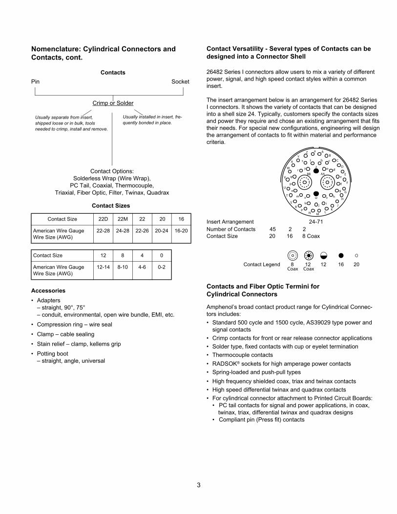
Contact Versatility - Several types of Contacts can be designed into a Connector Shell
26482 Series I connectors allow users to mix a variety of differentpower, signal, and high speed contact styles within a commoninsert.
The insert arrangement below is an arrangement for 26482 SeriesI connectors. It shows the variety of contacts that can be designedinto a shell size 24. Typically, customers specify the contacts sizesand power they require and chose an existing arrangement that fitstheir needs. For special new configurations, engineering will designthe arrangement of contacts to fit within material and performancecriteria.
Insert Arrangement 24-71Number of Contacts 45 2 2Contact Size 20 16 8 Coax
Contact Legend 8 12 12 16 20
Contacts and Fiber Optic Termini forCylindrical Connectors
Amphenol’s broad contact product range for Cylindrical Connec-tors includes:• Standard 500 cycle and 1500 cycle, AS39029 type power and
signal contacts• Crimp contacts for front or rear release connector applications• Solder type, fixed contacts with cup or eyelet termination• Thermocouple contacts• RADSOK® sockets for high amperage power contacts• Spring-loaded and push-pull types• High frequency shielded coax, triax and twinax contacts• High speed differential twinax and quadrax contacts• For cylindrical connector attachment to Printed Circuit Boards:
• PC tail contacts for signal and power applications, in coax,twinax, triax, differential twinax and quadrax designs
• Compliant pin (Press fit) contacts
a
e
CB
Dd
f
E
g
F
i
Gh
j
m
p
n
q
rAABB
bX t
y
ZY
A
W
V
U
T
SR
PN M
LK
J
H
z
w
k
vx
s
u
c
Coax Coax
4
A B
AB
AB A
B
AB
Major MIL-Specifications by Type• Standard, SAE AS50151• Amphenol AC Threaded Series• Amphenol 97 Series• Proprietary Commercial Variations
• Older larger series of connectors• Found on many pieces of military equipment and commercial
applications• Mostly heavy current carrying connectors• Early types had only solder type contacts• Later revision to MIL Spec also added crimp type contacts• Amphenol supplies both the solder and crimp types to the
MIL Spec• Amphenol supplies both solder and crimp versions under pro-
prietary commercial part numbers• See Amphenol catalogs: – AC and SAE AS50151 IC-5 – 97 Series 12-022 – ACA-B and GT Series IC-4• Basic part number for SAE AS50151 Series as supplied by Amphenol is MS310X F or R† • SAE AS50151 threaded coupling - 1 key/keyway shell polarization
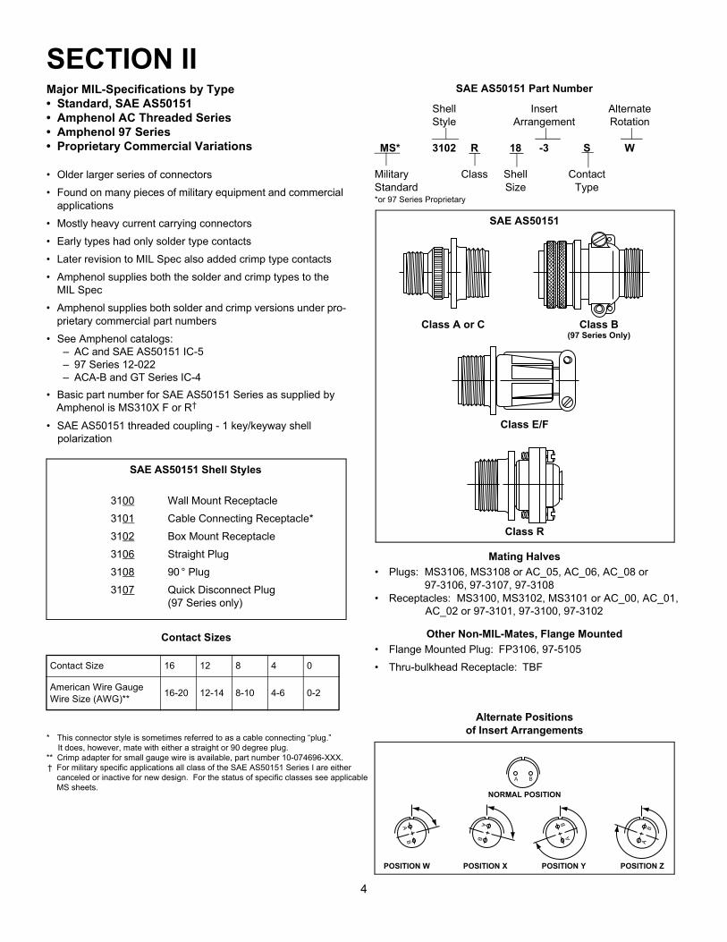
SAE AS50151 Shell Styles
3100 Wall Mount Receptacle3101 Cable Connecting Receptacle*3102 Box Mount Receptacle3106 Straight Plug3108 90 ° Plug3107 Quick Disconnect Plug
(97 Series only)
Contact Sizes
* This connector style is sometimes referred to as a cable connecting “plug.” It does, however, mate with either a straight or 90 degree plug.** Crimp adapter for small gauge wire is available, part number 10-074696-XXX.† For military specific applications all class of the SAE AS50151 Series I are either canceled or inactive for new design. For the status of specific classes see applicable MS sheets.
Contact Size 16 12 8 4 0
American Wire GaugeWire Size (AWG)** 16-20 12-14 8-10 4-6 0-2
Mating Halves• Plugs: MS3106, MS3108 or AC_05, AC_06, AC_08 or
97-3106, 97-3107, 97-3108• Receptacles: MS3100, MS3102, MS3101 or AC_00, AC_01, AC_02 or 97-3101, 97-3100, 97-3102
Other Non-MIL-Mates, Flange Mounted• Flange Mounted Plug: FP3106, 97-5105• Thru-bulkhead Receptacle: TBF
Alternate Positionsof Insert Arrangements
NORMAL POSITION
POSITION W POSITION X POSITION Y POSITION Z
SAE AS50151 Part Number
Shell Insert AlternateStyle Arrangement Rotation
MS* 3102 R 18 -3 S W
Military Class Shell ContactStandard Size Type*or 97 Series Proprietary
SAE AS50151
Class A or C Class B(97 Series Only)
Class E/F
Class R
SECTION II
5
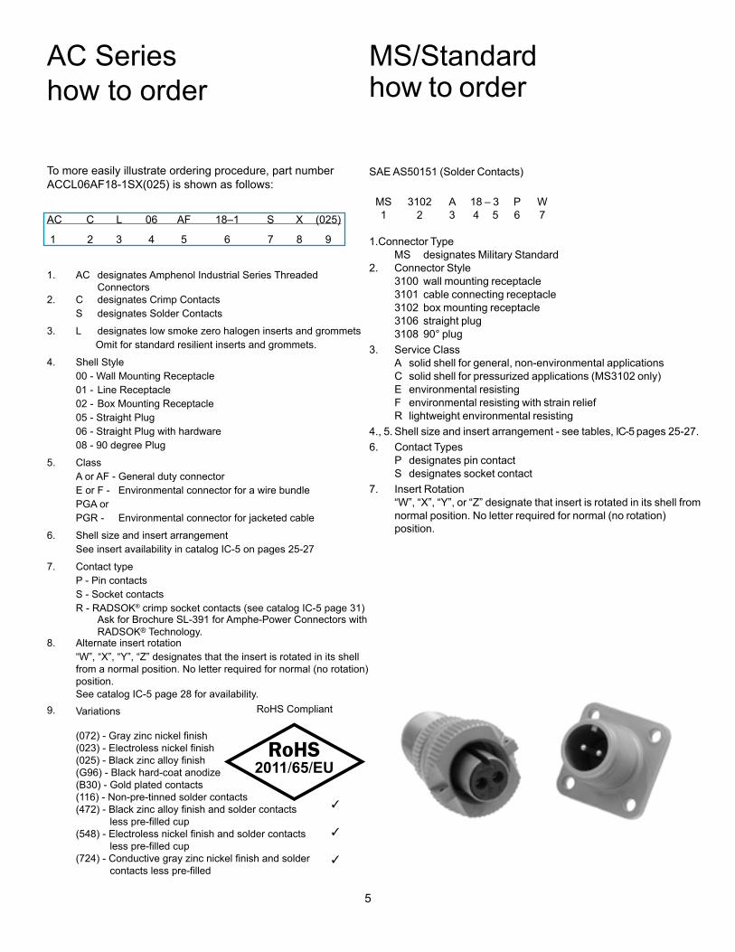
AC Serieshow to order
To more easily illustrate ordering procedure, part number ACCL06AF18-1SX(025) is shown as follows:
1.
AC designates Amphenol Industrial Series Threaded Connectors
2. C designates Crimp Contacts S designates Solder Contacts3. L designates low smoke zero halogen inserts and grommets Omit for standard resilient inserts and grommets.4. Shell Style 00 - Wall Mounting Receptacle 01 - Line Receptacle 02 - Box Mounting Receptacle 05 - Straight Plug 06 - Straight Plug with hardware 08 - 90 degree Plug5. Class A or AF - General duty connector E or F - Environmental connector for a wire bundle PGA or PGR - Environmental connector for jacketed cable6. Shell size and insert arrangement See insert availability in catalog IC-5 on pages 25-277. Contact type P - Pin contacts S - Socket contacts R - RADSOK® crimp socket contacts (see catalog IC-5 page 31) Ask for Brochure SL-391 for Amphe-Power Connectors with
RADSOK® Technology.8. Alternate insert rotation “W”, “X”, “Y”, “Z” designates that the insert is rotated in its shell
from a normal position. No letter required for normal (no rotation)position.
See catalog IC-5 page 28 for availability.9. RoHS Compliant
AC C L 06 AF 18–1 S X (025)
1 2 3 4 5 6 7 8 9
Variations
(072) - Gray zinc nickel finish(023) - Electroless nickel finish(025) - Black zinc alloy finish(G96) - Black hard-coat anodize(B30) - Gold plated contacts(116) - Non-pre-tinned solder contacts(472) - Black zinc alloy finish and solder contacts less pre-filled cup(548) - Electroless nickel finish and solder contacts less pre-filled cup(724) - Conductive gray zinc nickel finish and solder contacts less pre-filled
SAE AS50151 (Solder Contacts)
MS 3102 A 18 – 3 P W 1 2 3 4 5 6 7
1. Connector Type MS designates Military Standard2. Connector Style 3100 wall mounting receptacle 3101 cable connecting receptacle 3102 box mounting receptacle 3106 straight plug 3108 90° plug3. Service Class A solid shell for general, non-environmental applications C solid shell for pressurized applications (MS3102 only) E environmental resisting F environmental resisting with strain relief R lightweight environmental resisting4., 5. Shell size and insert arrangement - see tables, IC-5 pages 25-27.6. Contact Types P designates pin contact S designates socket contact7. Insert Rotation “W”, “X”, “Y”, or “Z” designate that insert is rotated in its shell from
normal position. No letter required for normal (no rotation)position.
MS/Standardhow to order
5
AC Serieshow to order
To more easily illustrate ordering procedure, part number ACCL06AF18-1SX(025) is shown as follows:
1.
AC designates Amphenol Industrial Series Threaded Connectors
2. C designates Crimp Contacts S designates Solder Contacts3. L designates low smoke zero halogen inserts and grommets Omit for standard resilient inserts and grommets.4. Shell Style 00 - Wall Mounting Receptacle 01 - Line Receptacle 02 - Box Mounting Receptacle 05 - Straight Plug 06 - Straight Plug with hardware 08 - 90 degree Plug5. Class A or AF - General duty connector E or F - Environmental connector for a wire bundle PGA or PGR - Environmental connector for jacketed cable6. Shell size and insert arrangement See insert availability in catalog IC-5 on pages 25-277. Contact type P - Pin contacts S - Socket contacts R - RADSOK® crimp socket contacts (see catalog IC-5 page 31) Ask for Brochure SL-391 for Amphe-Power Connectors with
RADSOK® Technology.8. Alternate insert rotation “W”, “X”, “Y”, “Z” designates that the insert is rotated in its shell
from a normal position. No letter required for normal (no rotation)position.
See catalog IC-5 page 28 for availability.9. RoHS Compliant
AC C L 06 AF 18–1 S X (025)
1 2 3 4 5 6 7 8 9
Variations
(072) - Gray zinc nickel finish(023) - Electroless nickel finish(025) - Black zinc alloy finish(G96) - Black hard-coat anodize(B30) - Gold plated contacts(116) - Non-pre-tinned solder contacts(472) - Black zinc alloy finish and solder contacts less pre-filled cup(548) - Electroless nickel finish and solder contacts less pre-filled cup(724) - Conductive gray zinc nickel finish and solder contacts less pre-filled
SAE AS50151 (Solder Contacts)
MS 3102 A 18 – 3 P W 1 2 3 4 5 6 7
1. Connector Type MS designates Military Standard2. Connector Style 3100 wall mounting receptacle 3101 cable connecting receptacle 3102 box mounting receptacle 3106 straight plug 3108 90° plug3. Service Class A solid shell for general, non-environmental applications C solid shell for pressurized applications (MS3102 only) E environmental resisting F environmental resisting with strain relief R lightweight environmental resisting4., 5. Shell size and insert arrangement - see tables, IC-5 pages 25-27.6. Contact Types P designates pin contact S designates socket contact7. Insert Rotation “W”, “X”, “Y”, or “Z” designate that insert is rotated in its shell from
normal position. No letter required for normal (no rotation)position.
MS/Standardhow to order
6
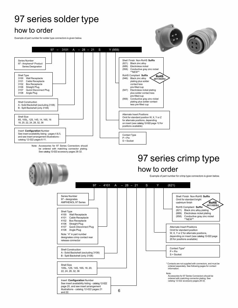
97 series solder typehow to order
97 – 3101 A – 28 – 21 S Y (959)
Series Number97 - Amphenol® Product Series Designation
Shell Type3100 Wall Receptacle3101 Cable Receptacle3102 Box Receptacle3106 Straight Plug3107 Quick Disconnect Plug3108 Angle Plug
Shell ConstructionA - Solid Backshell (excluding 3108)B - Split Backshell (only 3108)
Shell Size8S, 10SL, 12S, 14S, 14, 16S, 16 18, 20, 22, 24, 28, 32, 36
Insert NumberSee insert availability listing - pages 4 & 5, and see insert arrangement illustrations - catalog 12-022 pages 6-11.
Shell Finish Non-RoHS (621) Black zinc alloy(689) Electroless nickel(958) Conductive gray zinc nickel
**NEW**
RoHS Compliant (946) Black zinc alloy plating plus solder contact less (947) Electroless nickel plating plus solder contact less (959) Conductive gray zinc nickel
plating plus solder contactless pre-filled cup
Alternate Insert PositionsOmit for standard position W, X, Y or Z for alternate positions, depending on insert (see catalog 12-022 page 12 for positions available)
Contact TypeP = PinS = Socket
Example of part number for solder type connectors is given below.
Note: Accessories for 97 Series Connectors should be ordered with matching connec tor plating. See catalog 12-022 accessory pages 28-32.
* Contacts are not supplied with connectors, and must be ordered separately. See following pages for contact information.
Note: Accessories for 97 Series Connectors should be ordered with matching connector plating. See catalog 12-022 accessory pages 28-32.
97 series crimp typehow to order
97 - 4101 A – 28 – 21 S Y (621)
Series Number97 - designates AMPHENOL 97 Series
Shell Type4100 Wall Receptacle4101 Cable Receptacle4102 Box Receptacle4106 Straight Plug4107 Quick Disconnect Plug4108 Angle Plug
Note: “4” in part number designates crimp contact rear release connector
Shell ConstructionA - Solid Backshell (excluding 3108)B - Split Backshell (only 3108)
Shell Size10SL, 12S, 14S, 16S, 18, 20, 22, 24, 28, 32, 36
Insert NumberSee insert availability listing - catalog 12-022page 20, and see insert arrangementillustrations - catalog 12-022 pages 21and 22.
Shell Finish Non-RoHS Omit for standard bright
RoHS Compliant (621) Black zinc alloy plating(689) Electroless nickel plating (958) Conductive gray zinc nickel
**NEW**
Example of part number for crimp type connectors is given below.
Alternate Insert PositionsOmit for standard positionW, X, Y or Z for alternate positions, depending on insert (see catalog 12-022 page20 for positions available)
Contact Type*P = PinS = Socket
7
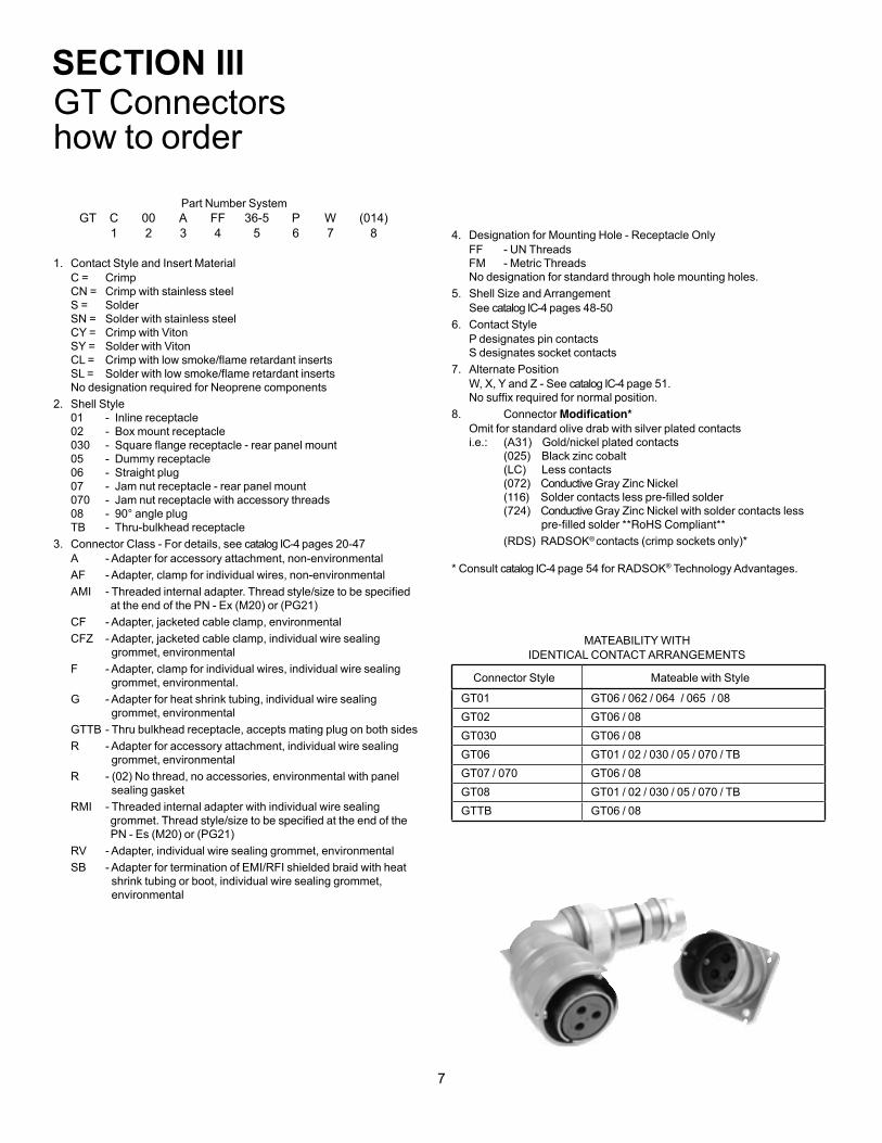
GT Connectorshow to order
Part Number SystemGT C 00 A FF 36-5 P W (014) 1 2 3 4 5 6 7 8
1. Contact Style and Insert MaterialC = Crimp CN = Crimp with stainless steel S = Solder SN = Solder with stainless steel CY = Crimp with Viton SY = Solder with Viton CL = SL = No designation required for Neoprene components
2. Shell Style01 - Inline receptacle 02 - Box mount receptacle 030 - 05 - Dummy receptacle 06 - Straight plug 07 - Jam nut receptacle - rear panel mount 070 - Jam nut receptacle with accessory threads 08 - 90° angle plug TB - Thru-bulkhead receptacle
3. Connector Class - For details, see catalog IC-4 pages 20-47A - Adapter for accessory attachment, non-environmentalAF - Adapter, clamp for individual wires, non-environmentalAMI at the end of the PN - Ex (M20) or (PG21) CF - Adapter, jacketed cable clamp, environmentalCFZ - Adapter, jacketed cable clamp, individual wire sealing grommet, environmentalF - Adapter, clamp for individual wires, individual wire sealing grommet, environmental.G - Adapter for heat shrink tubing, individual wire sealing grommet, environmentalGTTB - Thru bulkhead receptacle, accepts mating plug on both sidesR - Adapter for accessory attachment, individual wire sealing grommet, environmentalR - (02) No thread, no accessories, environmental with panel sealing gasketRMI - Threaded internal adapter with individual wire sealing PN - Es (M20) or (PG21) RV - Adapter, individual wire sealing grommet, environmentalSB - Adapter for termination of EMI/RFI shielded braid with heat shrink tubing or boot, individual wire sealing grommet, environmental
4. Designation for Mounting Hole - Receptacle OnlyFF - UN Threads FM - Metric Threads No designation for standard through hole mounting holes.
5. Shell Size and ArrangementSee catalog IC-4 pages 48-50
6. Contact StyleP designates pin contacts S designates socket contacts
7. Alternate PositionW, X, Y and Z - See catalog IC-4 page 51.
8. Connector Omit for standard olive drab with silver plated contacts i.e.: (A31) Gold/nickel plated contacts (025) Black zinc cobalt (LC) Less contacts
(072) Conductive Gray Zinc Nickel (724) Conductive Gray Zinc Nickel with solder contacts less
(RDS) RADSOK® contacts (crimp sockets only)*
* Consult catalog IC-4 page 54 for RADSOK® Technology Advantages.
MATEABILITY WITH IDENTICAL CONTACT ARRANGEMENTS
Connector Style Mateable with Style
GT01 GT06 / 062 / 064 / 065 / 08GT02 GT06 / 08GT030 GT06 / 08GT06 GT01 / 02 / 030 / 05 / 070 / TBGT07 / 070 GT06 / 08GT08 GT01 / 02 / 030 / 05 / 070 / TBGTTB GT06 / 08
SECTION III
853
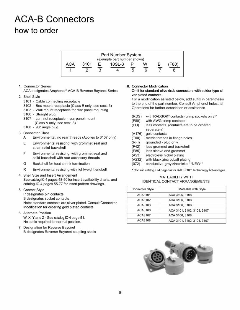
ACA-B Connectorshow to order
Part Number System(example part number shown)
ACA 3100 E 10SL-3 P W B (F80)1 2 3 4 5 6 7 8
1. Connector SeriesACA designates Amphenol® ACA-B Reverse Bayonet Series
2. Shell Style3100 - Wall mount receptacle for front panel mounting3101 - Cable connecting receptacle3102 - Box mount receptacle (Class E only, see sect. 3)3103 - Wall mount receptacle for rear panel mounting3106 - Straight plug3107 - Jam nut receptacle - rear panel mount
(Class A only, see sect. 3)3108 - 90° angle plug
3. Connector ClassA Environmental, no rear threads (Applies to 3107 only)E Environmental resisting, with grommet seal and
strain relief backshellF Environmental resisting, with grommet seal and
solid backshell with rear accessory threadsG Backshell for heat shrink terminationR Environmental resisting with lightweight endbell
4. Shell Size and Insert ArrangementSee pages 2-4 for insert availability charts, and pages 6-24 for insert pattern drawings.
5. Contact StyleP designates pin contactsS designates socket contactsNote: standard contacts are silver plated. Consult Connector Modification for ordering gold plated contacts.
6. Alternate PositionW, X, Y and Z - See page 5.No suffix required for normal position.
7. Designation for Reverse BayonetB designates Reverse Bayonet coupling shells
8. Connector ModificationOmit for standard olive drab connectors with solder type sil-ver plated contacts.For a modification as listed below, add suffix in parenthesis to the end of the part number. Consult Amphenol Industrial Operations for further description or assistance.
(RDS) with Radsock contacts(F80) with AWG crimp contacts(FO) less contacts. (contacts are to be ordered
separately)(A176) gold contacts(T00) metric threads in flange holes(RFI) grounded - plug only(F42) less grommet and backshell(F85) less sleeve and grommet (A23) electroless nickel plating(A232) with black zinc cobalt plating
MATEABILITY WITHIDENTICAL CONTACT ARRANGEMENTS
This catalog is on the Amphenol website:www.amphenol-industrial.com.
See www.amphenol-industrial.com andwww.amphenol-aerospace.comfor the broad range of interconnection products offered by Amphenol.
Connector Style Mateable with Style
ACA3100 ACA 3106, 3108ACA3101 ACA 3106, 3108ACA3102 ACA 3106, 3108ACA3103 ACA 3106, 3108ACA3106 ACA 3100, 3101, 3102, 3103, 3107ACA3107 ACA 3106, 3108ACA3108 ACA 3100, 3101, 3102, 3103, 3107
(072) conductive gray zinc nickel **NEW**
3101
53
Amphenol ACA-B Connectorshow to order, connector intermateability
Part Number System(example part number shown)
ACA 3100 E 10SL-3 P W B (F80)1 2 3 4 5 6 7 8
1. Connector SeriesACA designates Amphenol® ACA-B Reverse Bayonet Series
2. Shell Style3100 - Wall mount receptacle for front panel mounting3101 - Cable connecting receptacle3102 - Box mount receptacle (Class E only, see sect. 3)3103 - Wall mount receptacle for rear panel mounting3106 - Straight plug3107 - Jam nut receptacle - rear panel mount
(Class A only, see sect. 3)3108 - 90° angle plug
3. Connector ClassA Environmental, no rear threads (Applies to 3107 only)E Environmental resisting, with grommet seal and
strain relief backshellF Environmental resisting, with grommet seal and
solid backshell with rear accessory threadsG Backshell for heat shrink terminationR Environmental resisting with lightweight endbell
4. Shell Size and Insert ArrangementSee pages 2-4 for insert availability charts, and pages 6-24 for insert pattern drawings.
5. Contact StyleP designates pin contactsS designates socket contactsNote: standard contacts are silver plated. Consult Connector Modification for ordering gold plated contacts.
6. Alternate PositionW, X, Y and Z - See page 5.No suffix required for normal position.
7. Designation for Reverse BayonetB designates Reverse Bayonet coupling shells
8. Connector ModificationOmit for standard olive drab connectors with solder type sil-ver plated contacts.For a modification as listed below, add suffix in parenthesis to the end of the part number. Consult Amphenol Industrial Operations for further description or assistance.
(RDS) with Radsock contacts(F80) with AWG crimp contacts(FO) less contacts. (contacts are to be ordered
separately)(A176) gold contacts(T00) metric threads in flange holes(RFI) grounded - plug only(F42) less grommet and backshell(F85) less sleeve and grommet (A23) electroless nickel plating(A232) with black zinc cobalt plating
MATEABILITY WITHIDENTICAL CONTACT ARRANGEMENTS
See www.amphenol-industrial.com andwww.amphenol-aerospace.comfor the broad range of interconnection products offered by Amphenol.
Connector Style Mateable with Style
ACA3100 ACA 3106, 3108ACA3101 ACA 3106, 3108ACA3102 ACA 3106, 3108ACA3103 ACA 3106, 3108ACA3106 ACA 3100, 3101, 3102, 3103, 3107ACA3107 ACA 3106, 3108ACA3108 ACA 3100, 3101, 3102, 3103, 3107
®
53
Amphenol ACA-B Connectorshow to order, connector intermateability
Part Number System(example part number shown)
ACA 3100 E 10SL-3 P W B (F80)1 2 3 4 5 6 7 8
1. Connector SeriesACA designates Amphenol® ACA-B Reverse Bayonet Series
2. Shell Style3100 - Wall mount receptacle for front panel mounting3101 - Cable connecting receptacle3102 - Box mount receptacle (Class E only, see sect. 3)3103 - Wall mount receptacle for rear panel mounting3106 - Straight plug3107 - Jam nut receptacle - rear panel mount
(Class A only, see sect. 3)3108 - 90° angle plug
3. Connector ClassA Environmental, no rear threads (Applies to 3107 only)E Environmental resisting, with grommet seal and
strain relief backshellF Environmental resisting, with grommet seal and
solid backshell with rear accessory threadsG Backshell for heat shrink terminationR Environmental resisting with lightweight endbell
4. Shell Size and Insert ArrangementSee pages 2-4 for insert availability charts, and pages 6-24 for insert pattern drawings.
5. Contact StyleP designates pin contactsS designates socket contactsNote: standard contacts are silver plated. Consult Connector Modification for ordering gold plated contacts.
6. Alternate PositionW, X, Y and Z - See page 5.No suffix required for normal position.
7. Designation for Reverse BayonetB designates Reverse Bayonet coupling shells
8. Connector ModificationOmit for standard olive drab connectors with solder type sil-ver plated contacts.For a modification as listed below, add suffix in parenthesis to the end of the part number. Consult Amphenol Industrial Operations for further description or assistance.
(RDS) with Radsock contacts(F80) with AWG crimp contacts(FO) less contacts. (contacts are to be ordered
separately)(A176) gold contacts(T00) metric threads in flange holes(RFI) grounded - plug only(F42) less grommet and backshell(F85) less sleeve and grommet (A23) electroless nickel plating(A232) with black zinc cobalt plating
MATEABILITY WITHIDENTICAL CONTACT ARRANGEMENTS
This catalog is on the Amphenol website:www.amphenol-industrial.com.
See www.amphenol-industrial.com andwww.amphenol-aerospace.comfor the broad range of interconnection products offered by Amphenol.
Connector Style Mateable with Style
ACA3100 ACA 3106, 3108ACA3101 ACA 3106, 3108ACA3102 ACA 3106, 3108ACA3103 ACA 3106, 3108ACA3106 ACA 3100, 3101, 3102, 3103, 3107ACA3107 ACA 3106, 3108ACA3108 ACA 3100, 3101, 3102, 3103, 3107
®
ACA 3101, 3102, 3103, 3107
ACA 3101, 3102, 3103, 3107
(RDS) with RADSOK® contacts (crimp sockets only)*
* Consult catalog IC-4 page 54 for RADSOK® Technology Advantages.
See catalog IC-4 pages 48-50 for insert availability charts, and catalog IC-4 pages 55-77 for insert pattern drawings.
W, X, Y and Z - See catalog IC-4 page 51.
9
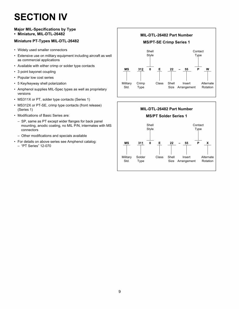
Major MIL-Specifications by Type• Miniature, MIL-DTL-26482
Miniature PT-Types MIL-DTL-26482
• Widely used smaller connectors• Extensive use on military equipment including aircraft as well
as commercial applications• Available with either crimp or solder type contacts• 3 point bayonet coupling• Popular low cost series• 5 Key/keyway shell polarization• Amphenol supplies MIL-Spec types as well as proprietary
versions• MS311X or PT, solder type contacts (Series 1)• MS312X or PT-SE, crimp type contacts (front release)
(Series 1)• Modifications of Basic Series are:
– SP, same as PT except wider flanges for back panel mounting, anodic coating, no MIL P/N, intermates with MS connectors
– Other modifications and specials available• For details on above series see Amphenol catalog:
– “PT Series” 12-070
MIL-DTL-26482 Part Number
MS/PT-SE Crimp Series 1
Shell ContactStyle Type
MS 312 0 E 22 – 55 P W
Military Crimp Class Shell Insert AlternateStd. Type Size Arrangement Rotation
MIL-DTL-26482 Part Number
MS/PT Solder Series 1
Shell ContactStyle Type
MS 311 0 E 22 – 55 P X
Military Solder Class Shell Insert AlternateStd. Type Size Arrangement Rotation
SECTION IV
10
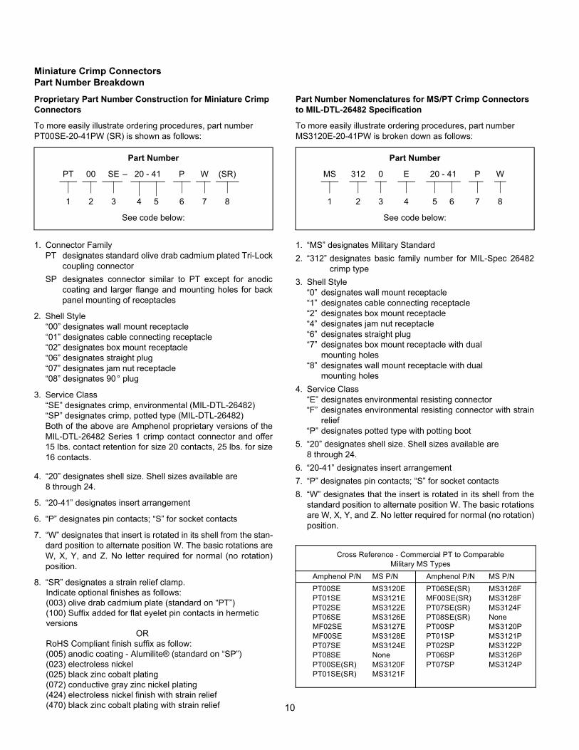
Miniature Crimp ConnectorsPart Number BreakdownProprietary Part Number Construction for Miniature Crimp Connectors
To more easily illustrate ordering procedures, part number PT00SE-20-41PW (SR) is shown as follows:
Part Number
PT 00 SE – 20 - 41 P W (SR)
1 2 3 4 5 6 7 8
See code below:
1. Connector FamilyPT designates standard olive drab cadmium plated Tri-Lock
coupling connectorSP designates connector similar to PT except for anodic
coating and larger flange and mounting holes for backpanel mounting of receptacles
2. Shell Style“00” designates wall mount receptacle“01” designates cable connecting receptacle“02” designates box mount receptacle“06” designates straight plug“07” designates jam nut receptacle“08” designates 90° plug
3. Service Class“SE” designates crimp, environmental (MIL-DTL-26482)“SP” designates crimp, potted type (MIL-DTL-26482)Both of the above are Amphenol proprietary versions of theMIL-DTL-26482 Series 1 crimp contact connector and offer15 lbs. contact retention for size 20 contacts, 25 lbs. for size16 contacts.
4. “20” designates shell size. Shell sizes available are8 through 24.
5. “20-41” designates insert arrangement
6. “P” designates pin contacts; “S” for socket contacts
7. “W” designates that insert is rotated in its shell from the stan-dard position to alternate position W. The basic rotations areW, X, Y, and Z. No letter required for normal (no rotation)position.
8. “SR” designates a strain relief clamp. Indicate optional finishes as follows: (003) olive drab cadmium plate (standard on “PT”) (100) Suffix added for flat eyelet pin contacts in hermetic versions OR RoHS Compliant finish suffix as follow: (005) anodic coating - Alumilite® (standard on “SP”) (023) electroless nickel (025) black zinc cobalt plating (072) conductive gray zinc nickel plating (424) electroless nickel finish with strain relief (470) black zinc cobalt plating with strain relief
Part Number Nomenclatures for MS/PT Crimp Connectors to MIL-DTL-26482 Specification
To more easily illustrate ordering procedures, part number MS3120E-20-41PW is broken down as follows:
Part Number
MS 312 0 E 20 - 41 P W
1 2 3 4 5 6 7 8
See code below:
1. “MS” designates Military Standard2. “312” designates basic family number for MIL-Spec 26482
crimp type3. Shell Style
“0” designates wall mount receptacle“1” designates cable connecting receptacle“2” designates box mount receptacle“4” designates jam nut receptacle“6” designates straight plug“7” designates box mount receptacle with dual
mounting holes“8” designates wall mount receptacle with dual
mounting holes4. Service Class
“E” designates environmental resisting connector“F” designates environmental resisting connector with strain
relief“P” designates potted type with potting boot
5. “20” designates shell size. Shell sizes available are8 through 24.
6. “20-41” designates insert arrangement7. “P” designates pin contacts; “S” for socket contacts8. “W” designates that the insert is rotated in its shell from the
standard position to alternate position W. The basic rotationsare W, X, Y, and Z. No letter required for normal (no rotation)position.
Cross Reference - Commercial PT to ComparableMilitary MS Types
Amphenol P/N MS P/N Amphenol P/N MS P/NPT00SE MS3120E PT06SE(SR) MS3126FPT01SE MS3121E MF00SE(SR) MS3128FPT02SE MS3122E PT07SE(SR) MS3124FPT06SE MS3126E PT08SE(SR) NoneMF02SE MS3127E PT00SP MS3120PMF00SE MS3128E PT01SP MS3121PPT07SE MS3124E PT02SP MS3122PPT08SE None PT06SP MS3126PPT00SE(SR) MS3120F PT07SP MS3124PPT01SE(SR) MS3121F
11
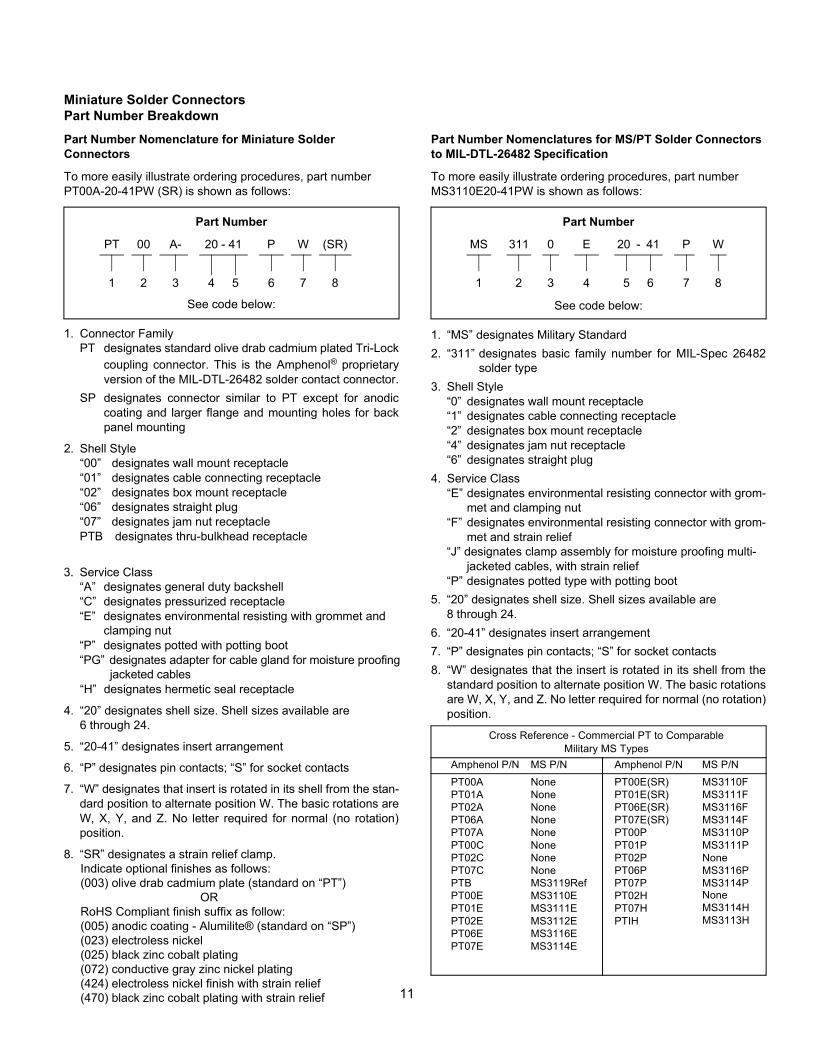
Miniature Solder ConnectorsPart Number BreakdownPart Number Nomenclature for Miniature SolderConnectors
To more easily illustrate ordering procedures, part number PT00A-20-41PW (SR) is shown as follows:
Part Number
PT 00 A- 20 - 41 P W (SR)
1 2 3 4 5 6 7 8
See code below:
1. Connector FamilyPT designates standard olive drab cadmium plated Tri-Lock
coupling connector. This is the Amphenol® proprietaryversion of the MIL-DTL-26482 solder contact connector.
SP designates connector similar to PT except for anodiccoating and larger flange and mounting holes for backpanel mounting
2. Shell Style“00” designates wall mount receptacle“01” designates cable connecting receptacle“02” designates box mount receptacle“06” designates straight plug“07” designates jam nut receptaclePTB designates thru-bulkhead receptacle
3. Service Class“A” designates general duty backshell“C” designates pressurized receptacle“E” designates environmental resisting with grommet and clamping nut “P” designates potted with potting boot“PG” designates adapter for cable gland for moisture proofing jacketed cables“H” designates hermetic seal receptacle
4. “20” designates shell size. Shell sizes available are6 through 24.
5. “20-41” designates insert arrangement
6. “P” designates pin contacts; “S” for socket contacts
7. “W” designates that insert is rotated in its shell from the stan-dard position to alternate position W. The basic rotations areW, X, Y, and Z. No letter required for normal (no rotation)position.
8. “SR” designates a strain relief clamp. Indicate optional finishes as follows: (003) olive drab cadmium plate (standard on “PT”) OR RoHS Compliant finish suffix as follow: (005) anodic coating - Alumilite® (standard on “SP”) (023) electroless nickel (025) black zinc cobalt plating (072) conductive gray zinc nickel plating (424) electroless nickel finish with strain relief (470) black zinc cobalt plating with strain relief
Part Number Nomenclatures for MS/PT Solder Connectors to MIL-DTL-26482 Specification
To more easily illustrate ordering procedures, part number MS3110E20-41PW is shown as follows:
Part Number
MS 311 0 E 20 - 41 P W
1 2 3 4 5 6 7 8
See code below:
1. “MS” designates Military Standard2. “311” designates basic family number for MIL-Spec 26482
solder type3. Shell Style
“0” designates wall mount receptacle“1” designates cable connecting receptacle“2” designates box mount receptacle“4” designates jam nut receptacle“6” designates straight plug
4. Service Class“E” designates environmental resisting connector with grom-
met and clamping nut“F” designates environmental resisting connector with grom-
met and strain relief“J” designates clamp assembly for moisture proofing multi-
jacketed cables, with strain relief“P” designates potted type with potting boot
5. “20” designates shell size. Shell sizes available are8 through 24.
6. “20-41” designates insert arrangement7. “P” designates pin contacts; “S” for socket contacts8. “W” designates that the insert is rotated in its shell from the
standard position to alternate position W. The basic rotationsare W, X, Y, and Z. No letter required for normal (no rotation)position.
Cross Reference - Commercial PT to ComparableMilitary MS Types
Amphenol P/N MS P/N Amphenol P/N MS P/NPT00A None PT00E(SR) MS3110FPT01A None PT01E(SR) MS3111FPT02A None PT06E(SR) MS3116FPT06A None PT07E(SR) MS3114FPT07A None PT00P MS3110PPT00C None PT01P MS3111PPT02C None PT02P NonePT07C None PT06P MS3116PPTB MS3119Ref PT07P MS3114PPT00E MS3110E PT02HPT01E MS3111E PT07HPT02E MS3112E PTIHPT06E MS3116E
None
PT07E MS3114E
MS3114HMS3113H
12
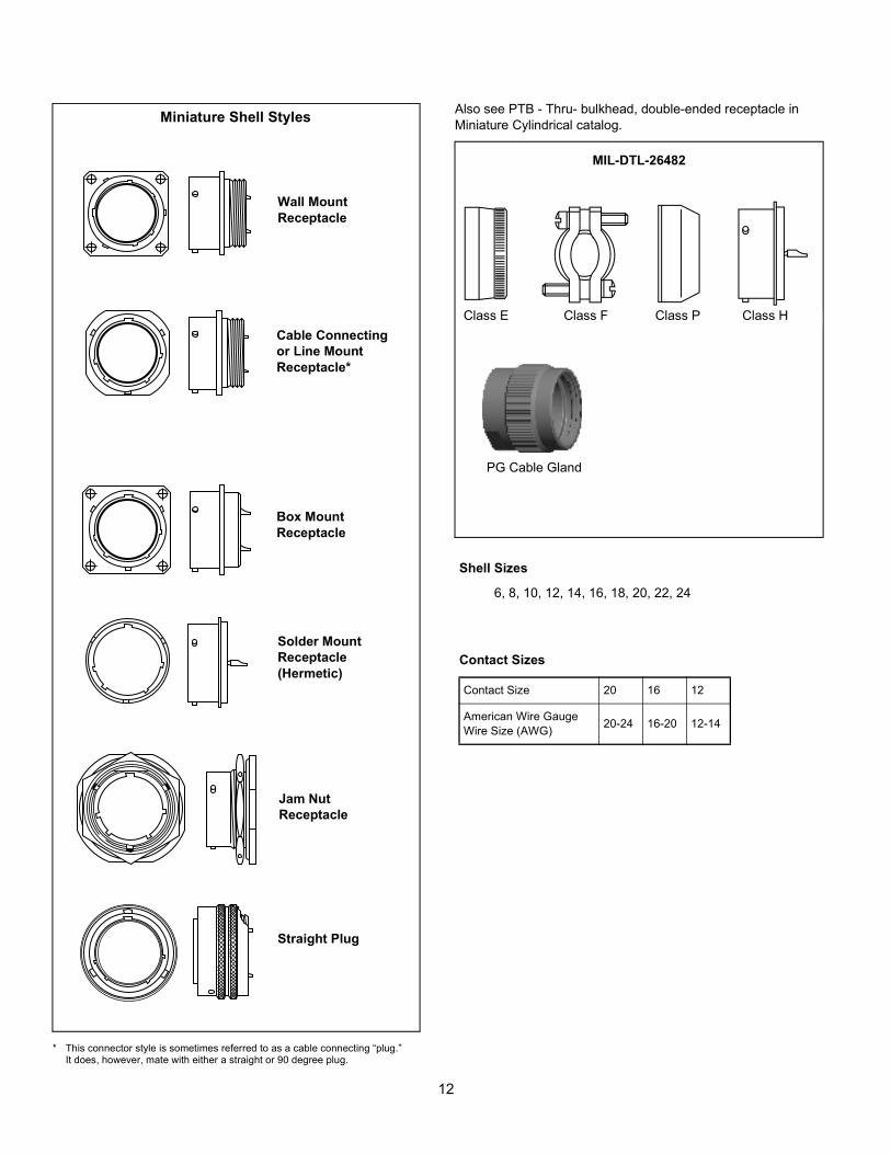
Also see PTB - Thru- bulkhead, double-ended receptacle in Miniature Cylindrical catalog.Miniature Shell Styles
Wall MountReceptacle
Cable Connectingor Line MountReceptacle*
Box MountReceptacle
Solder MountReceptacle(Hermetic)
Jam NutReceptacle
Straight Plug
MIL-DTL-26482
Class E Class F Class P Class H
PG Cable Gland
Shell Sizes
6, 8, 10, 12, 14, 16, 18, 20, 22, 24
Contact Sizes
Contact Size 20 16 12
American Wire GaugeWire Size (AWG) 20-24 16-20 12-14
* This connector style is sometimes referred to as a cable connecting “plug.”It does, however, mate with either a straight or 90 degree plug.
13
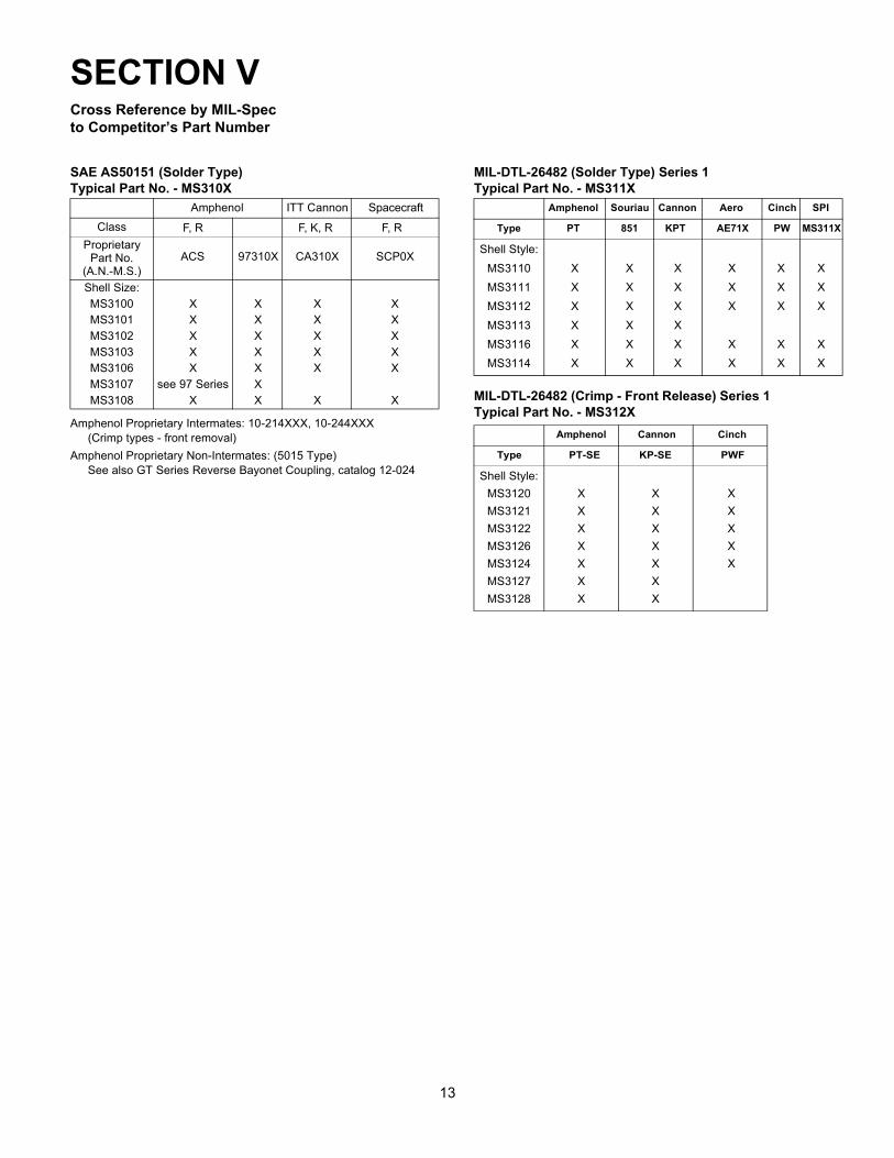
Cross Reference by MIL-Specto Competitor’s Part Number
Amphenol Proprietary Intermates: 10-214XXX, 10-244XXX(Crimp types - front removal)
Amphenol Proprietary Non-Intermates: (5015 Type)See also GT Series Reverse Bayonet Coupling, catalog 12-024
SAE AS50151 (Solder Type)Typical Part No. - MS310X
Amphenol ITT CannonClass
ProprietaryPart No.
(A.N.-M.S.)ACS 97310X CA310X
Shell Size:MS3100MS3101MS3102MS3103MS3106MS3107MS3108
XXXXX
see 97 SeriesX
XXXXXXX
XXXXX
X
MIL-DTL-26482 (Solder Type) Series 1Typical Part No. - MS311X
Type
Shell Style:MS3110MS3111MS3112MS3113MS3116MS3114
XXXXXX
XXXXXX
XXXXXX
XXX
XX
XXX
XX
XXX
XX
MIL-DTL-26482 (Crimp - Front Release) Series 1Typical Part No. - MS312X
Amphenol Cannon Cinch
Type PT-SE KP-SE PWF
Shell Style:MS3120MS3121MS3122MS3126MS3124MS3127MS3128
XXXXXXX
XXXXXXX
XXXXX
SECTION V
F, R F, K, R
Spacecraft
F, R
SCP0X
XXXXX
X
Amphenol Souriau Cannon Aero SPICinch
PT MS311XPWAE71XKPT851
14
Know the Language
Common terms you should know(listed alphabetically)
• Accessories - Mechanical devices, such as cable added to connector shells and other such hardware that are attach-able to connectors to make up the total connector configura-tion; while providing wire support and/or wire sealing
• Bayonet Coupling - A non-threaded, ramp type ofcoupling
• Cable Assembly - A cable with plugs or connectors on each end
• Configuration - Arrangement of contacts in a multiple-con-tact connector
• Contacts - Mechanical component to which electrical engagement is accomplished
• Contact Size - (Also known as Wire Gauge) - the largest wire that can be used with a specific contact
• Contact Spacing - The distance between the center-lines of adjacent contact areas.
• Coupling Nut - Outer threaded or grooved ring which holds mated pair together
• Crimp Contact - A contact to which wire is joined by mechanical squeeze
• EMI or RFI Backshell - A type of accessory to terminate wire shielding
• Environmentally Sealed - Connector provided with gas-kets, seals, potting or other devices to keep out moisture, dirt, air or dust that might reduce its performance
• Extraction/Removal Tool - A handheld tool used for remov-ing a contact from a connector.
• Fiber Optic Termini - Comparable to electrical pin and socket contacts, except they transmit data optically through fibers instead of electrically through wires.
• Gland - Resilient ring in rear accessory, provides seal on jacketed cable
• Grounding Fingers - A metal strap around plug shell for positive shell-to-shell conductivity/shielding
• Grommet - Resilient part at back of insert (attached or sepa-rate); gives wire moisture seal
• Hermetic - A connector with fused glass insert for airtightness
• Insert - The dielectric or insulating inner core, holdscontacts
• Insert Arrangement - The number, spacing and arrange-ment of contacts in a connector
• Insertion Tool - A small, handheld tool used to insert con-tacts into a connector
• Interfacial Seal - A resilient part on the face of pin inserts which provides moisture seal.
• Jam Nut - Hex nut that holds receptacle to a panel• Mating Pair - Two connectors that couple together. Shell
size insert arrangement and rotation must be compatible• Mating/Unmating Forces - Torque required to couple/
uncouple a mating pair of connectors or contacts• “O” Ring - Doughnut-shaped ring of rubber used as a seal
around the mating insulator interface of cylindricalconnectors
• Pin Contact - Male half of a mated pair of contacts*• Plating - The metal finish applied to contacts and or shell
components (protective) to resist corrosion and wear• Plug - The cable/coupling half of a mating pair• Potting Boot - A type of accessory which forms a mold for
potting compound• Rear Termination - An accessory which threads to back of
shell• Receptacle - The panel/receiving half of a mating pair• Sealing Plug - Plastic type slug, placed in unused grommet
holes to seal• Service Rating (Also known as Current Rating) - The
maximum voltage or current that a connector is designed to carry continuously.
• Shell - Houses insert and contacts• Socket Contact - Female half of a mated pair of contacts• Solder Contact - A contact to which wire is joined by solder-
ing. Has a cup, hollow cylinder, eyelet or hook to accept a wire for conventional soldered termination.
• Strain Relief (Also known as Cable Clamp) - A type of accessory which clamps wires for support
*Note: Male half always goes into female.
SECTION VIConnector:A device providing electricalor signal connection.It consists of a plug and receptacle.
15
Know the Language - Other Interconnection Product Terms
• Alternate Rotations - In cylindrical connectors: Rotation of either an insert or designated key/keyway locations (Alternate Keying) in a connector shell to a different angle than normal position. Allows for variations of mating two halves of cylindri-cal connectors.
• Anodize - Formation of a protective, insulating oxide layer on metal bay electrolytic action.
• Arc Resistance - The characteristic of insulating materials to resist carbonization (also known as tracking) of the material surface between electrodes resulting from voltage break-down.
• Attenuation - (this term is used in Filters) The ratio of the input to output power levels in a network (transmission line) when it is excited by a matched source and terminated in a matched load.
• Back-mounted - When a connector is mounted from the inside of a panel or box with its mounting flanges inside the equipment.
• Circuit - A complete path or electron flow from a negative ter-minal of voltage source through a conductor and back to the positive terminal.
• Closed Entry Socket Contacts - A female contact designed to prevent the entry of a pin or probing device having a cross-sectional dimension greater than the mating pin.
• Coaxial Cable - A high-bandwidth cable consisting of two concentric cylindrical conductors with a common axis that is used for high speed data communication and video signals.
• Compliant Contact - A press-fit type contact used to attach to a printed circuit board. Has an eyelet end.
• Conductivity - The ability of a material to conduct electric current, expressed in terms of the current per unit of applied voltage. It is reciprocal of resistivity.
• Contact Durability - Endurance measured by the number of insertion and withdrawal cycles that a connector withstands remaining within its specified performance level.
• Contact Engaging and Separating Force - Force needed to either engage or separate pins and sockets when they are out of connector inserts. Values are generally established for maximum and minimum forces.
• Contact Resistance - Maximum permitted electrical resis-tance of pin and socket contacts when assembled in a con-nector under typical service use.
• Contact Retention - The minimum axial load in either direc-tion that a contact must withstand while remaining firmly fixed in its normal position within the connector insert or housing.
• Continuity - A continuous path for the flow of current in an electrical circuit.
• Corrosion - The destruction of the surface of a metal by chemical reaction.
• Coupling Torque - Force required to rotate a coupling ring or jackscrew when engaging a mating pair of connectors.
• Diallyl Phthalate (DAP) - (Blue insert in 97 Series) A thermo-setting plastic that offers outstanding dimensional stability and resistance to most chemicals and chemical compounds.
• Dielectric - Any insulating medium that intervenes between two conductors.
• Dielectric Withstanding Voltage - Maximum potential gradi-ent that a dielectric material can withstand withoutfailure.
• Discontinuity - A broken connection or the loss of a specific connection characteristic.
• Edge Connector - One piece receptacle, containing female contacts designed to receive the edge of a printed circuit board and interconnect on which the male contacts are etched or printed. The connector may contain either a single or double row of female contacts.
• Edgeboard Connector - A connector that mates with printed wiring leads running to edge of a PC board.
• Feed-through - A conductor that connects patterns on oppo-site sides of a PC board. Also called interfacialconnection.
• Fiber Optics - A data transmission medium consisting of glass fibers. Light-emitting diodes send light through the fiber to a detractor, which then converts the light back into electri-cal signals.
• First Article - A sample part or assembly manufactured prior to the start of production for the purpose of assuring that the manufacturer is capable of manufacturing a product that will meet the requirements.
• Front-mounted - A connector is front-mounted when it is attached to the outside or mating side of a panel. (Can only be installed or removed from the outside of the equipment.
• Front Release Contacts - Connector contacts are released from the front side of the connector and then removed from the back wire side of the connector. The removal tool engages the front portion of the contact and pushes it out the back where it is removed by hand.
• Harsh or Hostile Environment Connector - A connector designed and engineered for operation in hostile environment conditions, such as extreme high temperatures of 677°C (1,250°F), extreme low temperatures of absolute zero and severe water tight conditions.
• Header - A feed through device that introduces a conductive path through an insulating plate.
• Hermaphroditic Connector - Interconnecting device in which both mating parts are identical at their mating surfaces. (Also called Sexless Connector)
• Hermaphroditic Contact - A contact in which both mating elements are precisely alike at their mating face.
• Input/Output Connector - A mating pair of connectors used to carry signals into and out of a panel-mounted subsystem. An example is connector pair that interconnects the individual back panels in a large array of panels.
• Insert Retention - Axial load in either direction that an insert must withstand without being dislocated from its normal posi-tion in the connector shell.
• Insertion Force - The effort, usually measured in ounces, required to engage mating components.
• Interchangeable - Characteristic of connectors in which one manufacturer’s connector can be replaced by the connector of another manufacturer and provide the same function in the same panel space as the connector it is replacing.
• Intermateable - Characteristic of connectors in which a con-nector half manufactured by one connector will mate directly with a connector half manufactured by a different company
SECTION VI
16
Know the Language - Other Interconnection Product Terms
• Keying - Mechanical arrangement of guide pins and sock-ets, keying plugs, contacts, bosses, slots, keyways, inserts or grooves in a connector housing, shell or insert that allows connectors of the same size and type to be lined up without the danger of making a wrong connection.
• Lanyard - A device attached to certain connectors that permit uncoupling and separation of connector halves by a pull on a wire or cable.
• Life Cycle - A test that indicates the time span before failure; the test occurs in a controlled, usually accelerated, environ-ment.
• Mass Termination - Method of termination in which termi-nals that pierce flat cable insulation without stripping to cold flow mate with conductors and form a metal-to-metal joint.
• Motherboard - A printed board used for interconnecting arrays of plug-in electronic modules.
• Operating Temperature - Maximum internal temperature-resistant capabilities of a connector in continuous service.
• Outgassing - De-aeration or other gaseous emission from a printed board assembly (printed board, component of con-nector) when exposed to a reduced pressure or heat, or both.
• Panel-mount - Fixing a connector half to a board, panel or frame. Usually, the female portion of the connector is mounted, and the male half is the removable portion.
• Plated Through-Hole - A hole-formed deposition of metal on the sides of the hole and on both sides of the base to provide electrical connection from the conductive pattern on one side to that on the opposite side of the PC board.
• Poke-Home Contact - Term applied to a male or female con-tact to which a wire has been permanently affixed prior to the assembly of the contact into the insert.
• Positioner - Device attached to the crimping tool to position conductor barrels between the indentors.
• Potting - Sealing of a component (for example the cable end of a multiple contact connector) with a plastic compound or material to exclude moisture, prevent short circuits and pro-vide strain relief.
• Pre-tinned - Solder applied to an electrical component prior to soldering.
• Pre-tinned Solder Cup - Solder cups with inner surfaces that have been pre-coated with a small amount of tin lead solder or RoHs approved solder.
• Press-fit Contact - Either a solid pin or a pin having a com-pliant member that makes an interference connection with a through-hole on a PC board. The pressure developed between interconnecting surfaces is sufficient to provide gas-tight electrical reliability without the use of solder.
• Qualified Products List (QPL) - A list of commercial prod-ucts that have been pretested and found to meet the require-ments of a specification, especially government specifications.
• Quick-disconnect Coupling - A design feature, apparent in the quick-disconnect connector; it permits relatively rapid joining and separation.
• RADSOK® Contact* - A unique socket contact design with a stamped and formed twisted inner grid. Socket cylinder within the female contact has several equally space longitudinal beams twisted into a hyperbolic shape. As male pin is inserted, axial members in the female half deflect, imparting high current flow across the connections.
• Ramp - The sloped channel that accepts the detent pin in a bayonet connector.
• Rear Release Contacts - Connector contacts are released and removed from the rear (wire side) of the connector. The removal tool engages the contact from the rear and pulls the contact out of the connector contact retainer.
• Rear Seal - Design feature that provides an environmental seal at the rear of plug or receptacle.
• Removable Contact - A contact that can be mechanically joined to or removed from an insert. Usually, special tools are required to lock the contact in place or remove it for repair or replacement.
• RoHS (Restrictions of Hazardous Substances) - The RoHS Directive bans the placing on the EU market of new electrical and electronic equipment containing more than agreed levels of lead, cadmium, mercury, hexavalent chro-mium, polybrominated biphenyl (PBB) and polybrominated diphenyl ether (PBDE) flame retardants.
• Scoop Proof - Design feature whereby exposed contacts of a connector cannot be touched or damaged by any portion of the mating connector.
• Serrations - Small grooves or indentations within a terminal wire barrel that increase the tensile strength and electrical conductivity of the crimped termination.
• Soldering - Process of joining metallic surfaces with solder, without the melting of the base metals. Soldering is an eco-nomical, versatile and fast termination method. A soldered connection has metallic continuity and excellent long term reliability.
• Splice Connector - A joint connecting conductors with good mechanical strength and good conductivity; a terminal that permanently joins two or more wires.
• Surface Mounting - The electrical connection of components to the surface of a conductive pattern without utilizing compo-nent holes.
• Thermal Shock - The effect of heat or cold applied to a material at such a rate that non-uniform thermal expansion or contraction occur. In connectors, the effect can cause inserts and other insulation materials to pull away from metal parts.
• Thermocouple Contact - A contact of special material used in connectors employed in thermocouple applications. Materi-als often used are iron, constantan, copper, chromel and alumel.
• Tuning Fork Contact - U-shaped female contact that resem-bles a tuning fork. It can be stamped or formed.
• Umbilical Connector - A connector used to connect cables to a rocket or missile prior to launching, and which is removed from the missile at the time of launching.
• Wire-Wrapped Connection (Also known as Solderless Wrap) - A solderless connection made by wrapping bare wire around a square or rectangular terminal with a power or hand tool.
* RADSOK® is a registered trademark of Amphenol Industrial Operations.
SECTION VI
17
Basic Questions to Determine Connector Requirements
• How many conductors (wires) and what are the wire gauges (size)?Smallest contact sizes available by Military Specifica-tions:SAE AS50151 - size 16MIL-DTL-26482 - size 20
• What’s your working voltage requirement?See catalog insert arrangement tableCatalog IC-4.........ACA-B and GT SeriesCatalog IC-5.........AC and SAE AS50151Catalog 12-070 .....PT Series
• Are you using your connector in a benign envi-ronment or a harsh environment?Harsh environment - will need gaskets, grommets and/or glands for environmental sealing
• Do you want to Solder or Crimp your wires?
• Are you going cable to cable or cable to panel?Cable plug to Cable receptacle use:– Straight plug with Inline cable receptacle– 90° Plug with Inline cable receptacle
Cable plug to Panel receptacle use:– Straight plug with either a wall mount receptacle,box mount receptacle, or jam nut receptacle
– 90° plug with either a wall mount receptacle, boxmount receptacle, or jam nut receptacle
• What’s your cable outer diameter (OD)? Or are you using discrete wires?
• Do you have any material restrictions?– RoHS requirement– Stainless steel– Aluminum– Neoprene– Silicon– Viton
• What type of plating or finish is preferred?Common platings or finishes:– Olive drab cadmium– Nickel– Black zinc alloy– Electroless nickel– Anodic coating– Gray ZnNi (Conductive)
• Will you need accessories?– Cable clamp– Bushing– Protection caps (metal or plastic)– Dummy receptacle
• Are you using an electrical or signal connector?POWER SAE AS50151 AC Threaded Amphenol GT Reverse Bayonet 97 Series – Standard contacts or (High Amperage) RADSOK®
MIL-DTL-26482Hermetic MIL-DTL-26482 PT
SIGNAL SAE AS50151 AC Threaded – High Frequency contacts
Filter PT AC Threaded (Amphe-dB - IDS-9)
Hermetic MIL-DTL-26482 PT AC Threaded
NOTE: Socket contacts are to be used in the connector feeding the powerNOTE: Not all connectors are limited to solely either power or signal. Many connectors can perform both functions.
SECTION VI, cont.
33
What do you need to Sell?
A Basic Product Knowledge• Why connectors are needed• Nomenclature (component parts)• Typical terms or descriptive words• Pertinent references to MIL-Spec• Cross reference Amphenol P/N to MIL P/N
A Catalog• Know how it is organized• Keep it current• Add your own notes for reference
Know Our Websitewww.amphenol-industrial.com
• Quickly navigate on-line to -• Connector Catalogs• Service Instructions• Your Contact Information• Markets Served• Connector Basics has this brochure and other
valuable basic connector information• Amphenol One for Distributor Information and
Latest Product NewsKnow Your Organization and Ours
• Who has pricing & delivery data• Who has technical data• Who can expedite• Who can negotiate• A back up for each of the above
Know Yourself and Your Competitors• What is negotiable at your account• What are your strong points• What are your weak points• What are your protection points• Who is your competition
Know Your Customers• What are their Needs?• Company Needs – Personal Needs
Learn to Listen (and to See)• What are they saying?• What do they mean?
– How they say it may mean more than what they say– What you both see may say more than conversationEach account is unique
• Don’t use a carbon copy approach• Let your customers know you see them that way
Take time to know the people you deal with• Both at your account and your facility• Manage your time and territory like assets• If business or potential isn’t there, maybe you shouldn’t be
ConclusionThe data in this booklet was designed to provide you with basic information on Amphenol Industrial connectorproducts.
In order to effectively sell, it is important to remember that knowing your customer and your product go handin hand.
The sale begins with you!
SECTION VI, cont.
18
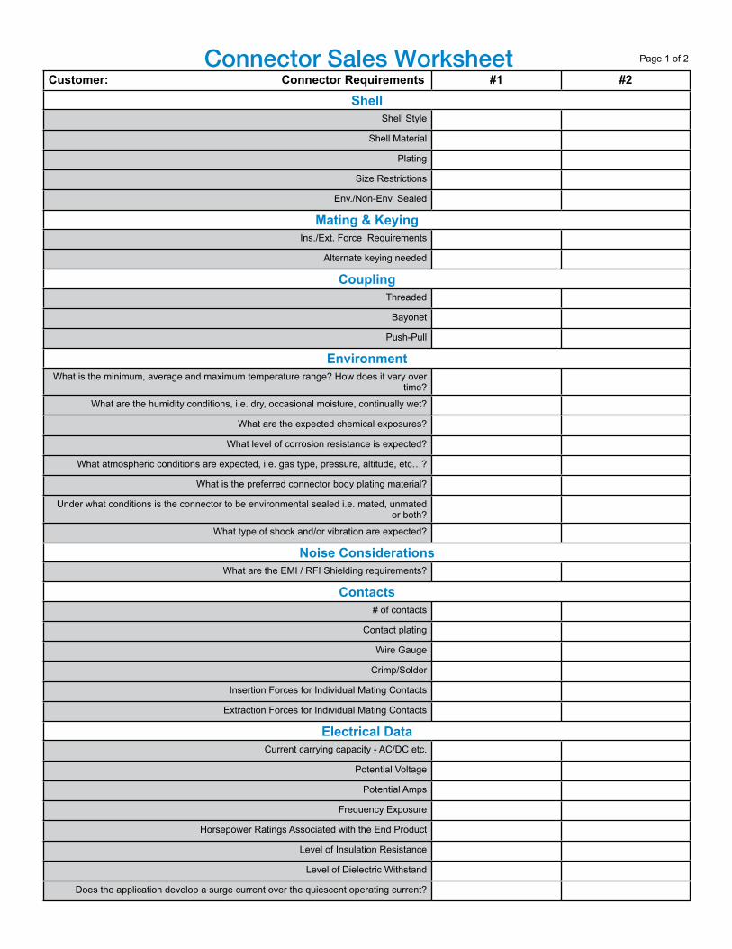
Customer: Connector Requirements #1 #2Shell
Shell Style
Shell Material
Plating
Size Restrictions
Env./Non-Env. Sealed
Mating & KeyingIns./Ext. Force Requirements
Alternate keying needed
CouplingThreaded
Bayonet
Push-Pull
EnvironmentWhat is the minimum, average and maximum temperature range? How does it vary over
time?
What are the humidity conditions, i.e. dry, occasional moisture, continually wet?
What are the expected chemical exposures?
What level of corrosion resistance is expected?
What atmospheric conditions are expected, i.e. gas type, pressure, altitude, etc…?
What is the preferred connector body plating material?
Under what conditions is the connector to be environmental sealed i.e. mated, unmated or both?
What type of shock and/or vibration are expected?
Noise ConsiderationsWhat are the EMI / RFI Shielding requirements?
Contacts# of contacts
Contact plating
Wire Gauge
Crimp/Solder
Insertion Forces for Individual Mating Contacts
Extraction Forces for Individual Mating Contacts
Electrical DataCurrent carrying capacity - AC/DC etc.
Potential Voltage
Potential Amps
Frequency Exposure
Horsepower Ratings Associated with the End Product
Level of Insulation Resistance
Level of Dielectric Withstand
Does the application develop a surge current over the quiescent operating current?
Connector Sales Worksheet Page 1 of 2
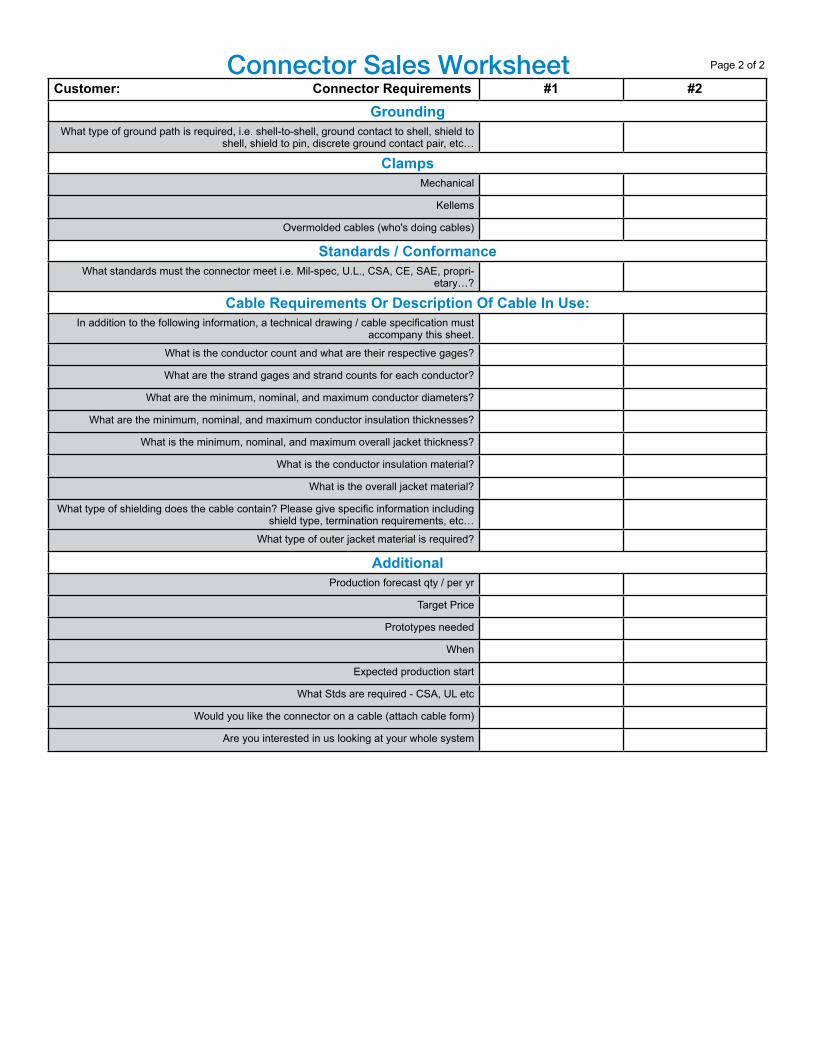
Customer: Connector Requirements #1 #2Grounding
What type of ground path is required, i.e. shell-to-shell, ground contact to shell, shield to shell, shield to pin, discrete ground contact pair, etc…
ClampsMechanical
Kellems
Overmolded cables (who's doing cables)
Standards / ConformanceWhat standards must the connector meet i.e. Mil-spec, U.L., CSA, CE, SAE, propri-
etary…?
Cable Requirements Or Description Of Cable In Use:In addition to the following information, a technical drawing / cable specification must
accompany this sheet.
What is the conductor count and what are their respective gages?
What are the strand gages and strand counts for each conductor?
What are the minimum, nominal, and maximum conductor diameters?
What are the minimum, nominal, and maximum conductor insulation thicknesses?
What is the minimum, nominal, and maximum overall jacket thickness?
What is the conductor insulation material?
What is the overall jacket material?
What type of shielding does the cable contain? Please give specific information including shield type, termination requirements, etc…
What type of outer jacket material is required?
AdditionalProduction forecast qty / per yr
Target Price
Prototypes needed
When
Expected production start
What Stds are required - CSA, UL etc
Would you like the connector on a cable (attach cable form)
Are you interested in us looking at your whole system
Connector Sales Worksheet Page 2 of 2

So, You Want to Know Connectors...
REFERENCE GUIDE to Cylindrical ConnectorsLearn the Amphenol Connector Language
www.ampheno l - indust r ia l .comNotice: Specifications are subject to change without notice. Contact your nearest Amphenol Corporation Sales Office for the latest specifications. All statements, information and data given herein are believed to be accurate and reliable but are presented without guarantee, warranty, or responsibility of any kind expressed or implied. Statements or suggestions concerning possible use of our products are made without representation or warranty that any such use is free of patent infringement and are not recommendations to infringe any patent. The user should not assume that all safety measures are indicated or that other measures may not be required. Specifications are typical and may not apply to all connectors.
IB-6-4
AMPHENOL CORPORATION Amphenol IndustrialPhone: 888-364-9011191 Delaware AvenueSidney, NY 13838-1395www.amphenol-industrial.com
3/22/2017